

Page 1

SHGPCBAUTO-001
13397576
Ä.Hlmä
L-force Controls
Software Manual
PC-based Automation
Industrial PC
Parameter setting & configuration
L
Page 2

Page 3

Industrial PC | Parameter setting & configuration
Contents
Contents
1 About this documentation . . . . . . . . . . . . . . . . . . . . . . . . . . . . . . . . . . . . . . . . . . . . . . . . . . . . . . . . . 9
1.1 Document history . . . . . . . . . . . . . . . . . . . . . . . . . . . . . . . . . . . . . . . . . . . . . . . . . . . . . . . . . . . . . . . 12
1.2 Conventions used . . . . . . . . . . . . . . . . . . . . . . . . . . . . . . . . . . . . . . . . . . . . . . . . . . . . . . . . . . . . . . . 13
1.3 Terminology used . . . . . . . . . . . . . . . . . . . . . . . . . . . . . . . . . . . . . . . . . . . . . . . . . . . . . . . . . . . . . . . 14
1.4 Notes used. . . . . . . . . . . . . . . . . . . . . . . . . . . . . . . . . . . . . . . . . . . . . . . . . . . . . . . . . . . . . . . . . . . . . . 15
2 Safety instructions . . . . . . . . . . . . . . . . . . . . . . . . . . . . . . . . . . . . . . . . . . . . . . . . . . . . . . . . . . . . . . . . 16
3 The PC-based Automation system. . . . . . . . . . . . . . . . . . . . . . . . . . . . . . . . . . . . . . . . . . . . . . . . . . . 17
4 Commissioning . . . . . . . . . . . . . . . . . . . . . . . . . . . . . . . . . . . . . . . . . . . . . . . . . . . . . . . . . . . . . . . . . . . 19
4.1 Identification . . . . . . . . . . . . . . . . . . . . . . . . . . . . . . . . . . . . . . . . . . . . . . . . . . . . . . . . . . . . . . . . . . . 20
4.1.1 Nameplate . . . . . . . . . . . . . . . . . . . . . . . . . . . . . . . . . . . . . . . . . . . . . . . . . . . . . . . . . . . . . . 21
4.1.2 Module labelling . . . . . . . . . . . . . . . . . . . . . . . . . . . . . . . . . . . . . . . . . . . . . . . . . . . . . . . . 21
4.1.3 Baseboard label . . . . . . . . . . . . . . . . . . . . . . . . . . . . . . . . . . . . . . . . . . . . . . . . . . . . . . . . . 22
4.2 Control elements. . . . . . . . . . . . . . . . . . . . . . . . . . . . . . . . . . . . . . . . . . . . . . . . . . . . . . . . . . . . . . . . 22
4.2.1 LEDs at the front of the monitor panel . . . . . . . . . . . . . . . . . . . . . . . . . . . . . . . . . . . . 22
4.2.2 Function keys. . . . . . . . . . . . . . . . . . . . . . . . . . . . . . . . . . . . . . . . . . . . . . . . . . . . . . . . . . . . 23
4.2.3 Changing the function key assignment in the »WebConfig« . . . . . . . . . . . . . . . 26
4.2.4 Changing the function key assignment in the L-force »Engineer«. . . . . . . . . . 27
4.3 Technical background information . . . . . . . . . . . . . . . . . . . . . . . . . . . . . . . . . . . . . . . . . . . . . . . 29
4.3.1 Data management . . . . . . . . . . . . . . . . . . . . . . . . . . . . . . . . . . . . . . . . . . . . . . . . . . . . . . 29
4.3.2 Starting process . . . . . . . . . . . . . . . . . . . . . . . . . . . . . . . . . . . . . . . . . . . . . . . . . . . . . . . . . 29
4.4 Configuring the Industrial PC . . . . . . . . . . . . . . . . . . . . . . . . . . . . . . . . . . . . . . . . . . . . . . . . . . . . 30
4.4.1 Touch display calibration. . . . . . . . . . . . . . . . . . . . . . . . . . . . . . . . . . . . . . . . . . . . . . . . . 31
4.4.2 Establishing an automatic dial-up connection . . . . . . . . . . . . . . . . . . . . . . . . . . . . . 32
4.4.3 Entering the IP address of the Industrial PC. . . . . . . . . . . . . . . . . . . . . . . . . . . . . . . . 32
4.4.3.1 Industrial PCs with a touch panel/with an external monitor. . . . . . 33
4.4.3.2 Industrial PC without touch panel/without external monitor. . . . . 33
4.4.4 Establishing Windows® CE access rights . . . . . . . . . . . . . . . . . . . . . . . . . . . . . . . . . . 34
4.4.4.1 Setting up Windows® CE users in the »WebConfig« . . . . . . . . . . . . . 34
4.4.4.2 Setting up Windows® CE users in the »Engineer« . . . . . . . . . . . . . . . . 35
5 System structure. . . . . . . . . . . . . . . . . . . . . . . . . . . . . . . . . . . . . . . . . . . . . . . . . . . . . . . . . . . . . . . . . . 36
5.1 Engineering PC. . . . . . . . . . . . . . . . . . . . . . . . . . . . . . . . . . . . . . . . . . . . . . . . . . . . . . . . . . . . . . . . . . 36
5.2 Industrial PC . . . . . . . . . . . . . . . . . . . . . . . . . . . . . . . . . . . . . . . . . . . . . . . . . . . . . . . . . . . . . . . . . . . . 36
5.2.1 Centralised control system . . . . . . . . . . . . . . . . . . . . . . . . . . . . . . . . . . . . . . . . . . . . . . . 37
5.2.2 IPC data manager. . . . . . . . . . . . . . . . . . . . . . . . . . . . . . . . . . . . . . . . . . . . . . . . . . . . . . . . 37
2.5 EN - 01/2012 L 3
Page 4

Industrial PC | Parameter setting & configuration
6 Parameterisation using the L-force »Engineer« . . . . . . . . . . . . . . . . . . . . . . . . . . . . . . . . . . . . . . . 38
6.1 Parameterisation via codes . . . . . . . . . . . . . . . . . . . . . . . . . . . . . . . . . . . . . . . . . . . . . . . . . . . . . . 38
6.2 Addressing structure in the »Engineer«. . . . . . . . . . . . . . . . . . . . . . . . . . . . . . . . . . . . . . . . . . . 39
6.2.1 Volatile data of an »Engineer« project . . . . . . . . . . . . . . . . . . . . . . . . . . . . . . . . . . . . 40
6.2.2 Saving data permanently . . . . . . . . . . . . . . . . . . . . . . . . . . . . . . . . . . . . . . . . . . . . . . . . 41
6.3 Parameter reference . . . . . . . . . . . . . . . . . . . . . . . . . . . . . . . . . . . . . . . . . . . . . . . . . . . . . . . . . . . . 41
6.4 Representation of the parameters. . . . . . . . . . . . . . . . . . . . . . . . . . . . . . . . . . . . . . . . . . . . . . . . 42
6.4.1 Parameters with read access . . . . . . . . . . . . . . . . . . . . . . . . . . . . . . . . . . . . . . . . . . . . . 42
6.4.2 Parameters with write access . . . . . . . . . . . . . . . . . . . . . . . . . . . . . . . . . . . . . . . . . . . . 42
6.4.2.1 Parameters with a setting range . . . . . . . . . . . . . . . . . . . . . . . . . . . . . . . . 42
6.4.2.2 Parameters with a selection list. . . . . . . . . . . . . . . . . . . . . . . . . . . . . . . . . 42
6.4.2.3 Parameters with a bit-coded setting . . . . . . . . . . . . . . . . . . . . . . . . . . . . 43
6.4.2.4 Parameters with subcodes . . . . . . . . . . . . . . . . . . . . . . . . . . . . . . . . . . . . . 43
7 Web-based parameterisation with »WebConfig« . . . . . . . . . . . . . . . . . . . . . . . . . . . . . . . . . . . . . 44
7.1 Parameterisation via codes . . . . . . . . . . . . . . . . . . . . . . . . . . . . . . . . . . . . . . . . . . . . . . . . . . . . . . 44
7.2 Requirements for working with the web-based parameterisation. . . . . . . . . . . . . . . . . . 45
7.2.1 Online connection between the Engineering PC and Industrial PC . . . . . . . . . . 45
7.2.2 Setting IP addresses . . . . . . . . . . . . . . . . . . . . . . . . . . . . . . . . . . . . . . . . . . . . . . . . . . . . . 45
7.3 Start of the web-based parameterisation . . . . . . . . . . . . . . . . . . . . . . . . . . . . . . . . . . . . . . . . . 47
7.3.1 Start at the Engineering PC. . . . . . . . . . . . . . . . . . . . . . . . . . . . . . . . . . . . . . . . . . . . . . . 47
7.3.2 Start at the Industrial PC . . . . . . . . . . . . . . . . . . . . . . . . . . . . . . . . . . . . . . . . . . . . . . . . . 47
7.4 User interface. . . . . . . . . . . . . . . . . . . . . . . . . . . . . . . . . . . . . . . . . . . . . . . . . . . . . . . . . . . . . . . . . . . 49
7.4.1 Parameters of the standard device of the Industrial PC. . . . . . . . . . . . . . . . . . . . . 51
7.4.2 Diagnostics/Command execution . . . . . . . . . . . . . . . . . . . . . . . . . . . . . . . . . . . . . . . . 52
7.4.3 Logbook. . . . . . . . . . . . . . . . . . . . . . . . . . . . . . . . . . . . . . . . . . . . . . . . . . . . . . . . . . . . . . . . . 53
7.4.3.1 Explanations of the logbook entries, example . . . . . . . . . . . . . . . . . . . 53
7.4.3.2 Filter options . . . . . . . . . . . . . . . . . . . . . . . . . . . . . . . . . . . . . . . . . . . . . . . . . . 54
7.4.3.3 Time filter for the display of logbook entries. . . . . . . . . . . . . . . . . . . . . 54
7.4.3.4 Export logbook entries . . . . . . . . . . . . . . . . . . . . . . . . . . . . . . . . . . . . . . . . . 55
7.4.4 Device commands . . . . . . . . . . . . . . . . . . . . . . . . . . . . . . . . . . . . . . . . . . . . . . . . . . . . . . . 55
7.4.5 User management. . . . . . . . . . . . . . . . . . . . . . . . . . . . . . . . . . . . . . . . . . . . . . . . . . . . . . . 55
7.4.6 General parameters . . . . . . . . . . . . . . . . . . . . . . . . . . . . . . . . . . . . . . . . . . . . . . . . . . . . . 56
7.4.7 Extension card parameters . . . . . . . . . . . . . . . . . . . . . . . . . . . . . . . . . . . . . . . . . . . . . . . 56
7.4.7.1 CAN communication card (MC-CAN2) . . . . . . . . . . . . . . . . . . . . . . . . . . . 57
7.4.7.2 EtherCAT communication card (MC-ETC) . . . . . . . . . . . . . . . . . . . . . . . . 57
7.4.7.3 PROFIBUS master communication card (MC-PBM) . . . . . . . . . . . . . . . 58
7.4.7.4 Ethernet communication card (MC-ETH) . . . . . . . . . . . . . . . . . . . . . . . . 58
7.4.8 Polling . . . . . . . . . . . . . . . . . . . . . . . . . . . . . . . . . . . . . . . . . . . . . . . . . . . . . . . . . . . . . . . . . . 58
7.4.9 Language selection . . . . . . . . . . . . . . . . . . . . . . . . . . . . . . . . . . . . . . . . . . . . . . . . . . . . . . 58
7.4.10 Parameter list buttons . . . . . . . . . . . . . . . . . . . . . . . . . . . . . . . . . . . . . . . . . . . . . . . . . . . 58
4 L 2.5 EN - 01/2012
Page 5

Industrial PC | Parameter setting & configuration
Contents
8 Programming with the »PLC Designer« . . . . . . . . . . . . . . . . . . . . . . . . . . . . . . . . . . . . . . . . . . . . . .59
8.1 Basics . . . . . . . . . . . . . . . . . . . . . . . . . . . . . . . . . . . . . . . . . . . . . . . . . . . . . . . . . . . . . . . . . . . . . . . . . . 59
8.2 Configuration and parameterisation via the control application . . . . . . . . . . . . . . . . . . . 60
8.3 Accessing IPC parameters from the PLC. . . . . . . . . . . . . . . . . . . . . . . . . . . . . . . . . . . . . . . . . . . 61
8.3.1 The LDM_ParameterAccess_FB function block. . . . . . . . . . . . . . . . . . . . . . . . . . . . . 61
8.3.2 The LLS_AddLog function block - Generate logbook entry . . . . . . . . . . . . . . . . . . 63
9 IPC backup & restore . . . . . . . . . . . . . . . . . . . . . . . . . . . . . . . . . . . . . . . . . . . . . . . . . . . . . . . . . . . . . . 64
9.1 Introduction to »IPC Backup & Restore« . . . . . . . . . . . . . . . . . . . . . . . . . . . . . . . . . . . . . . . . . . 64
9.2 Differences between archive, backup and restore . . . . . . . . . . . . . . . . . . . . . . . . . . . . . . . . . 65
9.3 Function . . . . . . . . . . . . . . . . . . . . . . . . . . . . . . . . . . . . . . . . . . . . . . . . . . . . . . . . . . . . . . . . . . . . . . . . 66
9.4 Requirements. . . . . . . . . . . . . . . . . . . . . . . . . . . . . . . . . . . . . . . . . . . . . . . . . . . . . . . . . . . . . . . . . . . 68
9.5 Backup procedure . . . . . . . . . . . . . . . . . . . . . . . . . . . . . . . . . . . . . . . . . . . . . . . . . . . . . . . . . . . . . . . 68
9.6 Restore procedure. . . . . . . . . . . . . . . . . . . . . . . . . . . . . . . . . . . . . . . . . . . . . . . . . . . . . . . . . . . . . . . 71
9.7 Software update procedure. . . . . . . . . . . . . . . . . . . . . . . . . . . . . . . . . . . . . . . . . . . . . . . . . . . . . . 73
10 Data integrity in the case of a voltage failure. . . . . . . . . . . . . . . . . . . . . . . . . . . . . . . . . . . . . . . . . 75
10.1 Retain variables of the PLC. . . . . . . . . . . . . . . . . . . . . . . . . . . . . . . . . . . . . . . . . . . . . . . . . . . . . . . 75
10.2 Backup for systems with UPS . . . . . . . . . . . . . . . . . . . . . . . . . . . . . . . . . . . . . . . . . . . . . . . . . . . . 76
10.3 Backup for systems without UPS . . . . . . . . . . . . . . . . . . . . . . . . . . . . . . . . . . . . . . . . . . . . . . . . . 77
10.3.1 Persisting the PLC's retain variables. . . . . . . . . . . . . . . . . . . . . . . . . . . . . . . . . . . . . . . 77
10.3.2 Persisting the IPC parameterisation. . . . . . . . . . . . . . . . . . . . . . . . . . . . . . . . . . . . . . . 77
10.3.3 Persisting log files . . . . . . . . . . . . . . . . . . . . . . . . . . . . . . . . . . . . . . . . . . . . . . . . . . . . . . . 78
11 Replacing the Industrial PC . . . . . . . . . . . . . . . . . . . . . . . . . . . . . . . . . . . . . . . . . . . . . . . . . . . . . . . . . 79
11.1 Removing the connected Industrial PC . . . . . . . . . . . . . . . . . . . . . . . . . . . . . . . . . . . . . . . . . . . 79
11.2 Connecting the new Industrial PC . . . . . . . . . . . . . . . . . . . . . . . . . . . . . . . . . . . . . . . . . . . . . . . . 80
11.3 Adapting the »Engineer« project . . . . . . . . . . . . . . . . . . . . . . . . . . . . . . . . . . . . . . . . . . . . . . . . . 81
12 Remote maintenance and diagnostics . . . . . . . . . . . . . . . . . . . . . . . . . . . . . . . . . . . . . . . . . . . . . . .82
12.1 Remote Access Service (RAS) connection. . . . . . . . . . . . . . . . . . . . . . . . . . . . . . . . . . . . . . . . . . 82
12.1.1 RAS client configuration . . . . . . . . . . . . . . . . . . . . . . . . . . . . . . . . . . . . . . . . . . . . . . . . . 83
12.1.2 RAS settings with the web-based parameterisation. . . . . . . . . . . . . . . . . . . . . . . . 84
12.1.3 RAS settings in the »Engineer« . . . . . . . . . . . . . . . . . . . . . . . . . . . . . . . . . . . . . . . . . . . 85
12.2 telnet connection . . . . . . . . . . . . . . . . . . . . . . . . . . . . . . . . . . . . . . . . . . . . . . . . . . . . . . . . . . . . . . . 86
12.2.1 Settings of the web-based parameterisation . . . . . . . . . . . . . . . . . . . . . . . . . . . . . . 86
12.2.2 Settings in the »Engineer« . . . . . . . . . . . . . . . . . . . . . . . . . . . . . . . . . . . . . . . . . . . . . . . 86
2.5 EN - 01/2012 L 5
Page 6

Industrial PC | Parameter setting & configuration
12.3 FTP connection. . . . . . . . . . . . . . . . . . . . . . . . . . . . . . . . . . . . . . . . . . . . . . . . . . . . . . . . . . . . . . . . . . 88
12.3.1 FTP settings with the web-based parameterisation . . . . . . . . . . . . . . . . . . . . . . . . 88
12.3.2 FTP settings in the »Engineer«. . . . . . . . . . . . . . . . . . . . . . . . . . . . . . . . . . . . . . . . . . . . 89
12.3.3 FTP and web settings in the Internet Explorer . . . . . . . . . . . . . . . . . . . . . . . . . . . . . 90
12.4 Windows® CE functions . . . . . . . . . . . . . . . . . . . . . . . . . . . . . . . . . . . . . . . . . . . . . . . . . . . . . . . . . 92
12.4.1 Remote Display. . . . . . . . . . . . . . . . . . . . . . . . . . . . . . . . . . . . . . . . . . . . . . . . . . . . . . . . . . 95
12.5 logbook function. . . . . . . . . . . . . . . . . . . . . . . . . . . . . . . . . . . . . . . . . . . . . . . . . . . . . . . . . . . . . . . . 96
12.5.1 logbook query via »WebConfig« . . . . . . . . . . . . . . . . . . . . . . . . . . . . . . . . . . . . . . . . . . 97
12.5.1.1 logbook codes . . . . . . . . . . . . . . . . . . . . . . . . . . . . . . . . . . . . . . . . . . . . . . . . . 98
12.5.2 Logbook query in the »Engineer« . . . . . . . . . . . . . . . . . . . . . . . . . . . . . . . . . . . . . . . . . 98
12.5.2.1 Filtering logbook entries . . . . . . . . . . . . . . . . . . . . . . . . . . . . . . . . . . . . . 102
12.5.2.2 Logbook codes . . . . . . . . . . . . . . . . . . . . . . . . . . . . . . . . . . . . . . . . . . . . . . . . . 102
13 Visualisation with »VisiWinNET®« . . . . . . . . . . . . . . . . . . . . . . . . . . . . . . . . . . . . . . . . . . . . . . . . . . 103
13.1 Introduction to »VisiWinNET®« . . . . . . . . . . . . . . . . . . . . . . . . . . . . . . . . . . . . . . . . . . . . . . . . . . 103
13.1.1 »VisiWinNET®« Compact. . . . . . . . . . . . . . . . . . . . . . . . . . . . . . . . . . . . . . . . . . . . . . . . . 103
13.1.2 Licensing of the visualisation (lic file) . . . . . . . . . . . . . . . . . . . . . . . . . . . . . . . . . . . . . 104
13.2 Basic functions. . . . . . . . . . . . . . . . . . . . . . . . . . . . . . . . . . . . . . . . . . . . . . . . . . . . . . . . . . . . . . . . . . 104
13.2.1 Start the »VisiWinNET®« development system . . . . . . . . . . . . . . . . . . . . . . . . . . . . 104
13.2.1.1 »VisiWinNET®« Smart. . . . . . . . . . . . . . . . . . . . . . . . . . . . . . . . . . . . . . . . . . 104
13.2.2 Creating a new project . . . . . . . . . . . . . . . . . . . . . . . . . . . . . . . . . . . . . . . . . . . . . . . . . . . 105
13.2.3 Open the Project Explorer . . . . . . . . . . . . . . . . . . . . . . . . . . . . . . . . . . . . . . . . . . . . . . . . 106
13.2.1.2 »VisiWinNET®« Professional. . . . . . . . . . . . . . . . . . . . . . . . . . . . . . . . . . . . 104
13.2.2.1 Creating a new project in »VisiWinNET®« Smart . . . . . . . . . . . . . . . . . 105
13.2.2.2 Creating a new project in »VisiWinNET®« Professional . . . . . . . . . . . 105
6 L 2.5 EN - 01/2012
Page 7

Industrial PC | Parameter setting & configuration
Contents
13.3 Constellation and connection . . . . . . . . . . . . . . . . . . . . . . . . . . . . . . . . . . . . . . . . . . . . . . . . . . . . 107
13.3.1 Use the CoDeSys direct driver . . . . . . . . . . . . . . . . . . . . . . . . . . . . . . . . . . . . . . . . . . . . 108
13.3.1.1 Use the direct driver for visualisations under Windows CE. . . . . . . . 108
13.3.1.2 Use the direct driver for visualisations under Windows XP . . . . . . . 109
13.3.2 Inserting the OPC tunnel in »VisiWinNET®« . . . . . . . . . . . . . . . . . . . . . . . . . . . . . . . 110
13.3.3 The Lenze Variables Browser . . . . . . . . . . . . . . . . . . . . . . . . . . . . . . . . . . . . . . . . . . . . . 111
13.3.3.1 Browsing for variable definitions . . . . . . . . . . . . . . . . . . . . . . . . . . . . . . . 111
13.3.3.2 Accept variable definitions to project . . . . . . . . . . . . . . . . . . . . . . . . . . . 113
13.3.4 Entering variables manually. . . . . . . . . . . . . . . . . . . . . . . . . . . . . . . . . . . . . . . . . . . . . . 114
13.3.4.1 Using the SoftPLC OPC tunnel . . . . . . . . . . . . . . . . . . . . . . . . . . . . . . . . . . 114
13.3.4.2 Using the data manager OPC tunnel . . . . . . . . . . . . . . . . . . . . . . . . . . . . 114
13.3.4.3 Local use of CAN OPC tunnel. . . . . . . . . . . . . . . . . . . . . . . . . . . . . . . . . . . . 115
13.3.4.4 Using the Remote SoftPLC OPC tunnel . . . . . . . . . . . . . . . . . . . . . . . . . . 115
13.3.4.5 Using the Remote data manager OPC tunnel . . . . . . . . . . . . . . . . . . . . 115
13.3.4.6 Local use of Remote CAN OPC tunnel . . . . . . . . . . . . . . . . . . . . . . . . . . . 115
13.3.5 Linking control elements and variables . . . . . . . . . . . . . . . . . . . . . . . . . . . . . . . . . . . 116
13.3.6 Transferring an application to the target device . . . . . . . . . . . . . . . . . . . . . . . . . . . 116
13.4 Configuration of the OPC tunnel . . . . . . . . . . . . . . . . . . . . . . . . . . . . . . . . . . . . . . . . . . . . . . . . . 118
13.4.1 Local visualisation (integrated control system) . . . . . . . . . . . . . . . . . . . . . . . . . . . . 119
13.4.2 External visualisation (remote access) . . . . . . . . . . . . . . . . . . . . . . . . . . . . . . . . . . . . 120
13.4.3 External visu on a Windows XP/XP Embedded IPC (remote access) . . . . . . . . . 122
13.5 Lenze specifications - exception handling. . . . . . . . . . . . . . . . . . . . . . . . . . . . . . . . . . . . . . . . . 124
13.5.1 Install additional fonts . . . . . . . . . . . . . . . . . . . . . . . . . . . . . . . . . . . . . . . . . . . . . . . . . . . 124
13.5.2 No access to variables with AT declaration possible (CoDeSys direct driver) . 124
14 Parameter reference. . . . . . . . . . . . . . . . . . . . . . . . . . . . . . . . . . . . . . . . . . . . . . . . . . . . . . . . . . . . . . . 125
14.1 Structure of the parameter description . . . . . . . . . . . . . . . . . . . . . . . . . . . . . . . . . . . . . . . . . . . 125
14.1.1 Data types . . . . . . . . . . . . . . . . . . . . . . . . . . . . . . . . . . . . . . . . . . . . . . . . . . . . . . . . . . . . . . 126
14.1.2 Parameters with read access . . . . . . . . . . . . . . . . . . . . . . . . . . . . . . . . . . . . . . . . . . . . . 126
14.1.3 Parameters with write access . . . . . . . . . . . . . . . . . . . . . . . . . . . . . . . . . . . . . . . . . . . . 126
14.1.3.1 Parameters with a setting range . . . . . . . . . . . . . . . . . . . . . . . . . . . . . . . . 127
14.1.3.2 Parameters with a selection list. . . . . . . . . . . . . . . . . . . . . . . . . . . . . . . . . 127
14.1.3.3 Parameters with a bit-coded setting . . . . . . . . . . . . . . . . . . . . . . . . . . . . 127
14.1.3.4 Parameters with subcodes . . . . . . . . . . . . . . . . . . . . . . . . . . . . . . . . . . . . . 127
14.1.4 Parameter attributes . . . . . . . . . . . . . . . . . . . . . . . . . . . . . . . . . . . . . . . . . . . . . . . . . . . . 128
14.2 Parameters of standard devices . . . . . . . . . . . . . . . . . . . . . . . . . . . . . . . . . . . . . . . . . . . . . . . . . . 129
14.3 Ethernet interface (on board) . . . . . . . . . . . . . . . . . . . . . . . . . . . . . . . . . . . . . . . . . . . . . . . . . . . . 153
14.4 Panel . . . . . . . . . . . . . . . . . . . . . . . . . . . . . . . . . . . . . . . . . . . . . . . . . . . . . . . . . . . . . . . . . . . . . . . . . . . 155
14.5 PLC (Logic/Motion) . . . . . . . . . . . . . . . . . . . . . . . . . . . . . . . . . . . . . . . . . . . . . . . . . . . . . . . . . . . . . . 159
2.5 EN - 01/2012 L 7
Page 8

Industrial PC | Parameter setting & configuration
14.6 Industrial PC extension modules . . . . . . . . . . . . . . . . . . . . . . . . . . . . . . . . . . . . . . . . . . . . . . . . . 161
14.6.1 CAN communication card (MC-CAN2). . . . . . . . . . . . . . . . . . . . . . . . . . . . . . . . . . . . . 162
14.6.2 EtherCAT communication card (MC-ETC) . . . . . . . . . . . . . . . . . . . . . . . . . . . . . . . . . . 172
14.6.3 PROFIBUS master communication card (MC-PBM) . . . . . . . . . . . . . . . . . . . . . . . . . 207
14.6.4 Ethernet communication card (MC-ETH) . . . . . . . . . . . . . . . . . . . . . . . . . . . . . . . . . . 209
15 Glossary . . . . . . . . . . . . . . . . . . . . . . . . . . . . . . . . . . . . . . . . . . . . . . . . . . . . . . . . . . . . . . . . . . . . . . . . . 213
16 Index . . . . . . . . . . . . . . . . . . . . . . . . . . . . . . . . . . . . . . . . . . . . . . . . . . . . . . . . . . . . . . . . . . . . . . . . . . . . 217
Your opinion is important to us. . . . . . . . . . . . . . . . . . . . . . . . . . . . . . . . . . . . . . . . . . . . . . . . . . . . . . . . . 225
8 L 2.5 EN - 01/2012
Page 9

Industrial PC | Parameter setting & configuration
1 About this documentation
This documentation provides general information on the parameterisation and
configuration of an Industrial PC. The Industrial PC is the central control system of the PCbased Automation system.
The present manual is part of the "PC-based automation" manual collection which consists
of the following components:
Documentation Subject
System manuals
PC-based Automation
Communication manuals
PC-based Automation
(Software) manual
PC-based Automation
Operating Instructions
Embedded Line Panel PC
Operating Instructions
Command Station
Operating Instructions
Control Cabinet PC
Operating Instructions
HMI EL 100
Further software manuals • Global Drive Control (GDC)
• Control technology - system structure & configuration
• Visualisation - system structure & components
• CANopen control technology
• EtherCAT control technology
• PROFIBUS control technology
• Industrial PC - Parameterisation & Configuration
• EL x800 - Panel PC with TFT display
• CS x800 - Stand-alone operator terminal
• CPC 2800 - Control cabinet PC
• EL 1xx - HMI with Windows
• IPC as gateway - Parameterisation & Configuration
• »Engineer«
• »PLC Designer« / »PLC Designer - SoftMotion« / »PLC Designer - CANopen
• »VisiWinNET® Smart«
About this documentation
® CE
for runtime systems«
Information on the use of the IPCs beyond control technology can be found in the
System manuals which are designed to meet the respective case of application.
2.5 EN - 01/2012 L 9
Page 10

Industrial PC | Parameter setting & configuration
About this documentation
Further technical documentation for Lenze components
Further information on Lenze components which can be used in connection with "PC based
Automation" can be found in the following documentation:
Mounting & wiring Legend:
MA 8400 StateLine/HighLine Printed documentation
MA 9400 StateLine/HighLine Online help/PDF
MA EPM-Txxx (I/O system IP20) Abbreviations used:
MA EPM-Sxxx (I/O system 1000) SHB System Manual
MA 8200 vector BA Operating Instructions
EMC-compliant wiring 8200 vector MA Mounting Instructions
MA ECSxS/P/M/A axis modules SW Software manual
MA ECSxE power supply modules KHB Communication manual
Accordingly for built-in variants:
• Built-in unit
• Push-through technique
•Cold plate technology
MA MC-CAN2 communication card
MA MC-ETC communication card
MA MC-ETH communication card
MA MC-PBM communication card
MA MC-PBS communication card
MA MC-MPI communication card
MAs for the communication modules
Parameterisation, configuration, commissioning
SW 8400 StateLine/HighLine frequency inverters
SW 9400 StateLine/HighLine/PLC controller
9400 HighLine commissioning guideline
SHB I/O system IP20 (EPM-Txxx)
SHB I/O system 1000 (EPM-Sxxx)
SHB 8200 vector
BA ECSxS "Speed and Torque" axis module
BA ECSxP "Posi & Shaft" axis module
BA ECSxM "Motion" axis module
BA ECSxA "Application" axis module
BA ECSxE power supply module
KHBs for the communication modules
Programming
SW 9400 function library
Establishing a network
KHBs for the communication modules
10 L 2.5 EN - 01/2012
Page 11

Industrial PC | Parameter setting & configuration
About this documentation
Target group
This documentation is directed at persons who wish to parameterise, configure, and
diagnose a PC-based control system using an Industrial PC in conjunction with the L-force
»Engineer« Engineering software.
2.5 EN - 01/2012 L 11
Page 12

Industrial PC | Parameter setting & configuration
About this documentation
Document history
1.1 Document history
Version Description
1.0 07/2007 TD16 First edition control technology 1.0
1.5 11/2007 TD16 Updated parameter lists control technology 1.5, amended by the »WebConfig«
2.0 05/2008 TD11 Control technology 2.0, amended by the parameter lists for the MC-CAN2, MC-ETH,
2.1 08/2008 TD11 Control technology 2.1, "(in preparation!)" removed for Release EtherCAT,
2.2 05/2009 TD11 Control technology 2.2, update for the new software version
2.3 11/2009 TD11 Control technology 2.2.2, update for the new software version
2.4 01/2011 TD11 Control technology 2.5, update for the new software version
2.5 01/2012 TD11 Control technology 2.6, update for the new software version
and
MC-ETC communication cards.
Update EtherCAT parameters.
• Update of the German »WebConfig« user interface,
• Added default settings of IP addresses,
• Amended by the IP port in the system overviews,
• Added contents from system verification,
• Added ID numbers to document,
• Amended by the parameter list of the MC-PBM communication card.
•new chapter: Lenze specifications - exception handling
•new chapter: Configuration of the OPC tunnel
Tip!
Current documentation and software updates on Lenze products can be found on
the Internet in the "Services & Downloads" area under:
http://www.Lenze.com
12 L 2.5 EN - 01/2012
Page 13

1.2 Conventions used
This documentation uses the following conventions to distinguish between different types
of information:
Type of information Writing Examples/notes
Spelling of numbers
Decimal separator Point Generally the decimal point is used.
Text
Version information Text colour blue All pieces of information that only apply to or from a
Program name » « The Lenze PC software »Engineer«...
Window Italics The Message window... / The Options dialog box...
Variable identifier By setting bEnable to TRUE...
Control element Bold The OK button... / The Copy command... / The
Sequence of menu
commands
Keyboard command <Bold> Press <F1> to open the online help.
Program listings Courier
Keyword Courier bold
Industrial PC | Parameter setting & configuration
About this documentation
Conventions used
For example: 1234.56
specific software version are indicated accordingly in
this documentation.
Example: This function extension is available from
software version V3.0!
Properties tab... / The Name input field...
If several commands must be used in sequence to
carry out a function, then the individual commands
are separated by an arrow. Select File
If a command requires a combination of keys, a "+" is
placed between the key symbols:
With <Shift>+<ESC> you can...
IF var1 < var2 THEN
a = a + 1
END IF
Open to...
Hyperlink Underlined
Symbols
Page reference ( 13) Optically highlighted reference to another page. Is
Step-by-step instructions
Optically highlighted reference to another topic. Is
activated via mouse-click in this documentation.
activated via mouse-click in this documentation.
Step-by-step instructions are indicated by a
pictograph.
2.5 EN - 01/2012 L 13
Page 14

Industrial PC | Parameter setting & configuration
About this documentation
Terminology used
1.3 Terminology used
Term Meaning
»Engineer« Lenze engineering tools which support you throughout the whole life cycle of a
»Global Drive Control« / »GDC«
»PLC Designer«
Code "Container" for one or several parameters used for parameter setting or
Subcode If a code contains several parameters, the individual parameters are stored
IPC Industrial PC
PLC Programmable Logic Controller
machine with an Industrial PC - from planning to maintenance.
monitoring Lenze Servo Drives.
under "subcodes".
This manual uses a slash "/" as a separator between code and subcode
(e.g. "C00118/3").
14 L 2.5 EN - 01/2012
Page 15

1.4 Notes used
The following signal words and icons are used in this documentation to indicate dangers
and important information:
Safety instructions
Structure of safety instructions:
Pictograph and signal word!
(characterise the type and severity of danger)
Note
(describes the danger and gives information about how to prevent dangerous
situations)
Industrial PC | Parameter setting & configuration
About this documentation
Notes used
Pictograph Signal word Meaning
Danger! Danger of personal injury through dangerous electrical voltage
Danger! Danger of personal injury through a general source of danger
Stop! Danger of property damage
Application notes
Pictograph Signal word Meaning
Note! Important note to ensure trouble-free operation
Reference to an imminent danger that may result in death or serious
personal injury if the corresponding measures are not taken.
Reference to an imminent danger that may result in death or serious
personal injury if the corresponding measures are not taken.
Reference to a possible danger that may result in property damage if the
corresponding measures are not taken.
Tip! Useful tip for simple handling
Reference to another documentation
2.5 EN - 01/2012 L 15
Page 16

Industrial PC | Parameter setting & configuration
Safety instructions
2 Safety instructions
Please observe the following safety instructions when you want to commission a controller
or system using the Industrial PC.
Read the documentation supplied with the corresponding field device thoroughly
before starting to commission the devices with the Industrial PC!
The device documentation contains safety instructions which must be
observed!
Danger!
According to our present level of knowledge it is not possible to ensure the
absolute freedom from errors of a software.
If necessary, systems with built-in controllers must be provided with additional
monitoring and protective equipment according to relevant safety regulations
(e.g. law on technical equipment, regulations for the prevention of accidents), so
that an impermissible operating status does not endanger persons or facilities.
During commissioning persons must keep a safe distance from the motor or the
machine parts driven by the motor. Otherwise there would be a risk of injury by
the moving machine parts.
Stop!
If you change parameters in the »Engineer« or the »WebConfig« while a device
is connected online, the changes will be directly accepted by the device!
A wrong parameter setting can cause unpredictable motor movements. By
unintentional direction of rotation, too high speed or jerky operation, the driven
machine parts may be damaged!
16 L 2.5 EN - 01/2012
Page 17
Industrial PC | Parameter setting & configuration
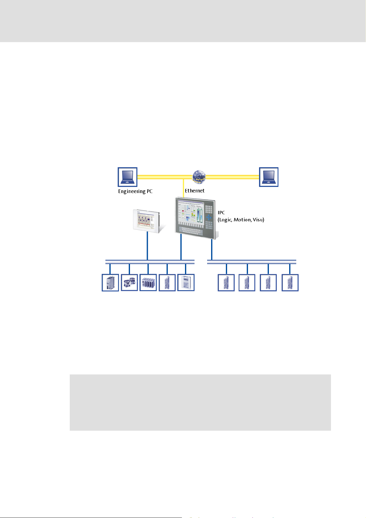
3 The PC-based Automation system
Industrial PCs (IPCs) keep finding their way into automation technology. Due to their
scaling options and various possibilities of combining visualisation and control in one
device, Industrial PCs offer great advantages for many applications.
Lenze Industrial PCs are available in the following software equipments:
Industrial PC as component, on request with operating system, without further
software
Industrial PC as visualisation system
Industrial PC as control and visualisation system
The PC-based Automation system enables central control of Logic and Motion systems.
The PC-based Automation system
For this pupose, Lenze provides well-matched system components:
Industrial PCs as control and visualisation system
– The IPC is the central component of the PC-based Automation system that uses the
Runtime Software to control the Logic and Motion functionalities.
– The IPC uses the fieldbus to communicate with the field devices.
– The IPC is available in various designs.
Note!
The PC-based Automation system also includes the EL 1xx PLC HMI series.
Regarding efficiency and other details, these devices differ considerably from
the Industrial PCs. However, the devices of the EL 1xx PLC HMI series are able to
perform smaller control tasks.
Engineering tools for the Engineering PC
– The Engineering PC uses the Ethernet to communicate with the IPC.
– Use the various Engineering tools to configure and parameterise the system.
2.5 EN - 01/2012 L 17
Page 18

Industrial PC | Parameter setting & configuration
The PC-based Automation system
Fieldbuses
Field devices
18 L 2.5 EN - 01/2012
Page 19

4 Commissioning
This chapter provides general information on the first commissioning of an Industrial PC.
Depending on the actual hardware installed, different settings are required to integrate
the Industrial PC for machine control purposes into a network.
Note!
• Please observe the following predefined IP addresses when commissioning
your IPC for the first time:
– Engineering PC: 192.168.5.100
– Industrial PC: 192.168.5.99
Further information on the setting of the IP address of your Industrial PC can be found in
the following section: Entering the IP address of the Industrial PC
Industrial PC | Parameter setting & configuration
Commissioning
( 32)
Read the Mounting Instructions accompanying the controller first before you start
working!
The Mounting Instructions contain safety instructions which must be observed!
Further information on the device-specific properties can be found in the
Hardware Manual of the corresponding Industrial PC.
2.5 EN - 01/2012 L 19
Page 20
Industrial PC | Parameter setting & configuration
Commissioning
Identification
4.1 Identification
Note!
Here the documentation provides some general information on the
commissioning of an Industrial PC. Depending on the design and version of the
Industrial PC, the commissioning can vary.
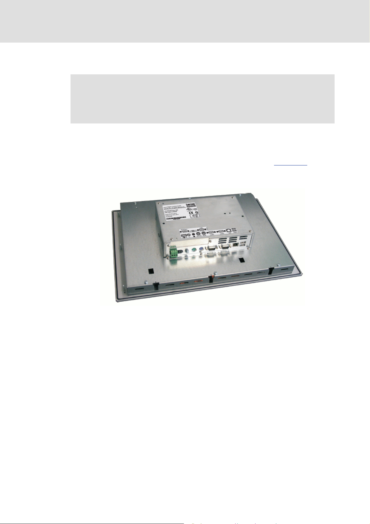
Every Industrial PC is provided with a nameplate containing the device data. The device
data is required for being able to select the IPC in the »Engineer« corresponding to the
hardware components installed.
The Industrial PC can be identified by means of the nameplate. Nameplate
The nameplate contains information on the components installed which is required for
initial commissioning.
( 21)
20 L 2.5 EN - 01/2012
Page 21
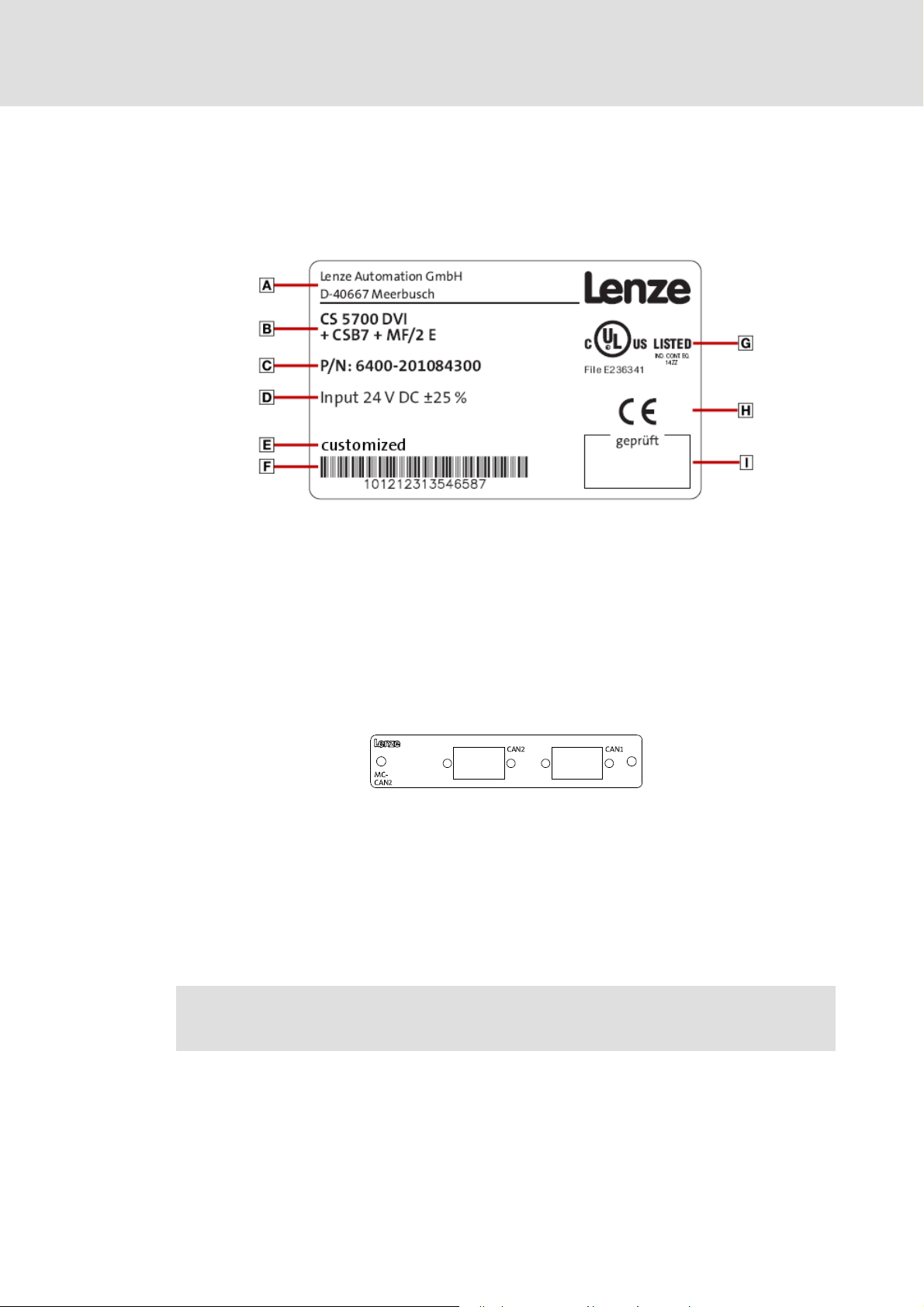
4.1.1 Nameplate
The nameplate is...
...on the back of the panel for Industrial PCs of the EL and CS series,
For cabinet PCs of the CPC series on the housing.
Industrial PC | Parameter setting & configuration
Commissioning
Identification
Manufacturer
address
Material number
(customised)
Inspector's signature
4.1.2 Module labelling
The extension module labelling indicates the connection options to the fieldbus.
Depending on the configuration, one or more fieldbus adapter are mounted.
[4-1] Module labelling, example: the CAN communication card (MC-CAN2)
Type designation Catalogue / order
Bar code
with serial number
number
Certification CE mark
Tip!
Data provided by module labelling facilitate the integration of IPC device modules
into the L-force »Engineer«.
Technical data
Further information on the L-force »Engineer« can be found in the online
documentation of the L-force »Engineer«.
2.5 EN - 01/2012 L 21
Page 22

Industrial PC | Parameter setting & configuration
Commissioning
Control elements
4.1.3 Baseboard label
The baseboard label illustrates possible connections to the main board of the IPC.
Therefore, quick wiring of the individual components is possible.
4.2 Control elements
Depending on the equipment level and the model series, the different series are provided
with different control elements. The monitor panels and embedded line front modules are
equipped with status LEDs, function keys and special keys.
The IPC can be operated
as standard via the function keys of the command stations and embedded line PCs next
to the panel,
or via the on-screen keyboard or touchscreen.
If extensive diagnostics and configurations are required, the Industrial PC can also be
operated via external input devices such as a keyboard or mouse.
4.2.1 LEDs at the front of the monitor panel
The LEDs are located at the front of the panel. Depending on the model design, the LEDs are
positioned in different places.
Power LED
The green power LED is lit when an input voltage is supplied.
If the LED is blinking, the Industrial PC is in service mode.
Fail LED
The red fail LED is lit if a fault has occurred in the current supply.
If the LED is blinking, there is no screen signal.
22 L 2.5 EN - 01/2012
Page 23

Status LED (optional)
Note!
In the case of some IPC variants the status LED has no function!
Depending on the IPC design, the status LED can signalise the access to the respective
storage medium.
Further information on the device-dependent function of the light-emitting diodes
can be found in the Hardware Manual of the corresponding Industrial PC.
4.2.2 Function keys
At the least the panel is equipped with function keys F1, F2, F3 and a shift key at the front
module. The following description applies to the IPC series ELxx00, MPxx00 and CSxx00.
Here the function keys are located on the right of the display. Depending on the IPC design,
the position and assignment of the keys may vary.
Industrial PC | Parameter setting & configuration
Commissioning
Control elements
The key assignment of function keys F1-F3 can be parameterised via the »Engineer«or the
»WebConfig«.
Changing the function key assignment in the »WebConfig«
Changing the function key assignment in the L-force »Engineer« ( 27)
Every function key has two functions. The additional functions can be activated via a
service mode.
( 26)
How to activate the service mode:
1. Keep the key
• While the LED is blinking, the service mode is active.
2. In the service mode the screen brightness can be changed via F2 and F3.
• F1 starts the control panel.
3. To return to standard mode, wait until the green LED is lit permanently or press
again.
pressed until the green LED is blinking.
2.5 EN - 01/2012 L 23
Page 24
Industrial PC | Parameter setting & configuration
Commissioning
Control elements
Function key "F1"
Standard mode: The key sends the key code for <SHIFT>+<F1>.
• In the standard assignment, <F1> starts the input panel.
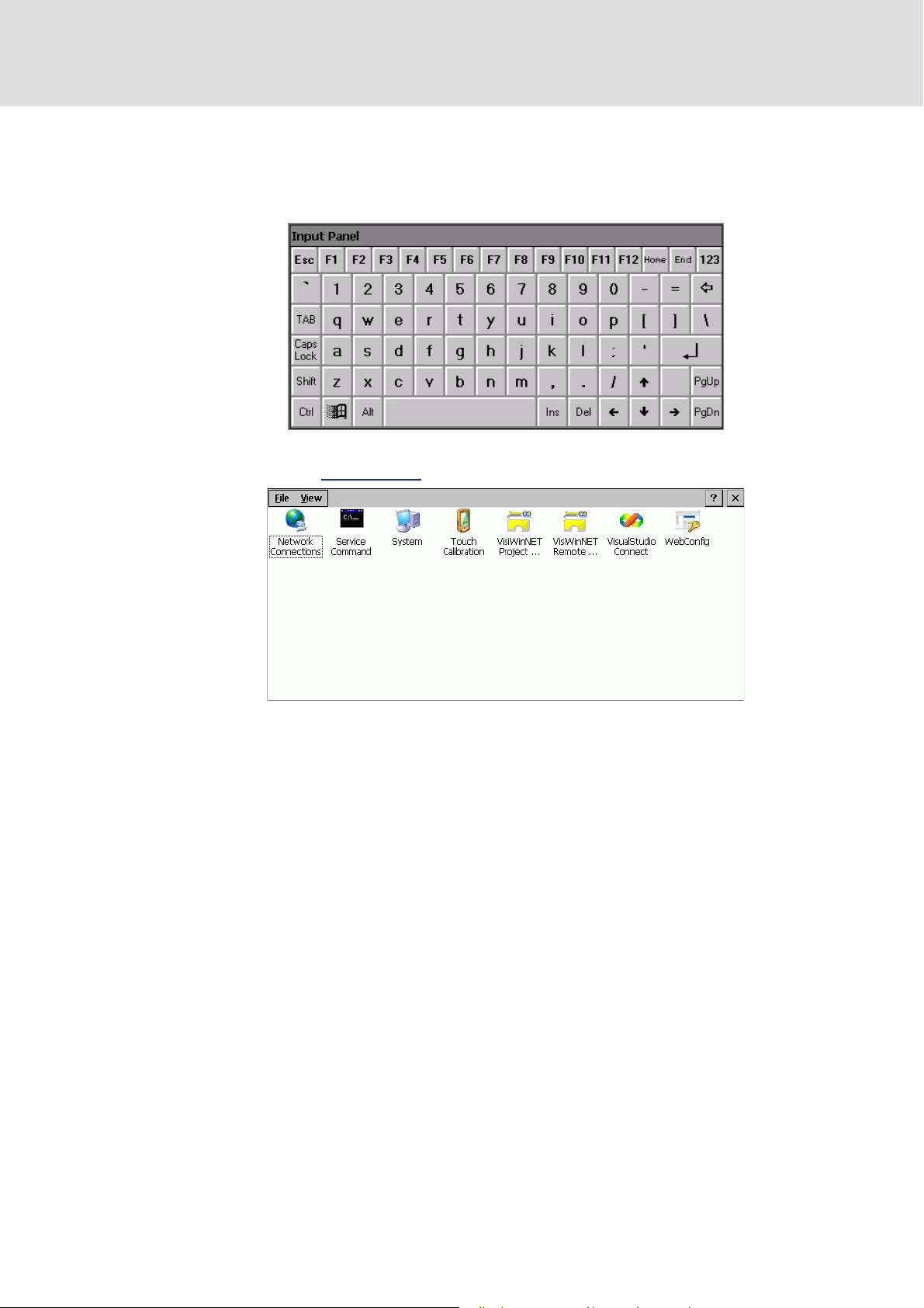
In the service mode, <F1> sends the key code for <SHIFT>+<F4> and starts the Windows®
CE control panel: Control panel
( 25)
The View menu provides further options for representation.
24 L 2.5 EN - 01/2012
Page 25
Industrial PC | Parameter setting & configuration
Control panel
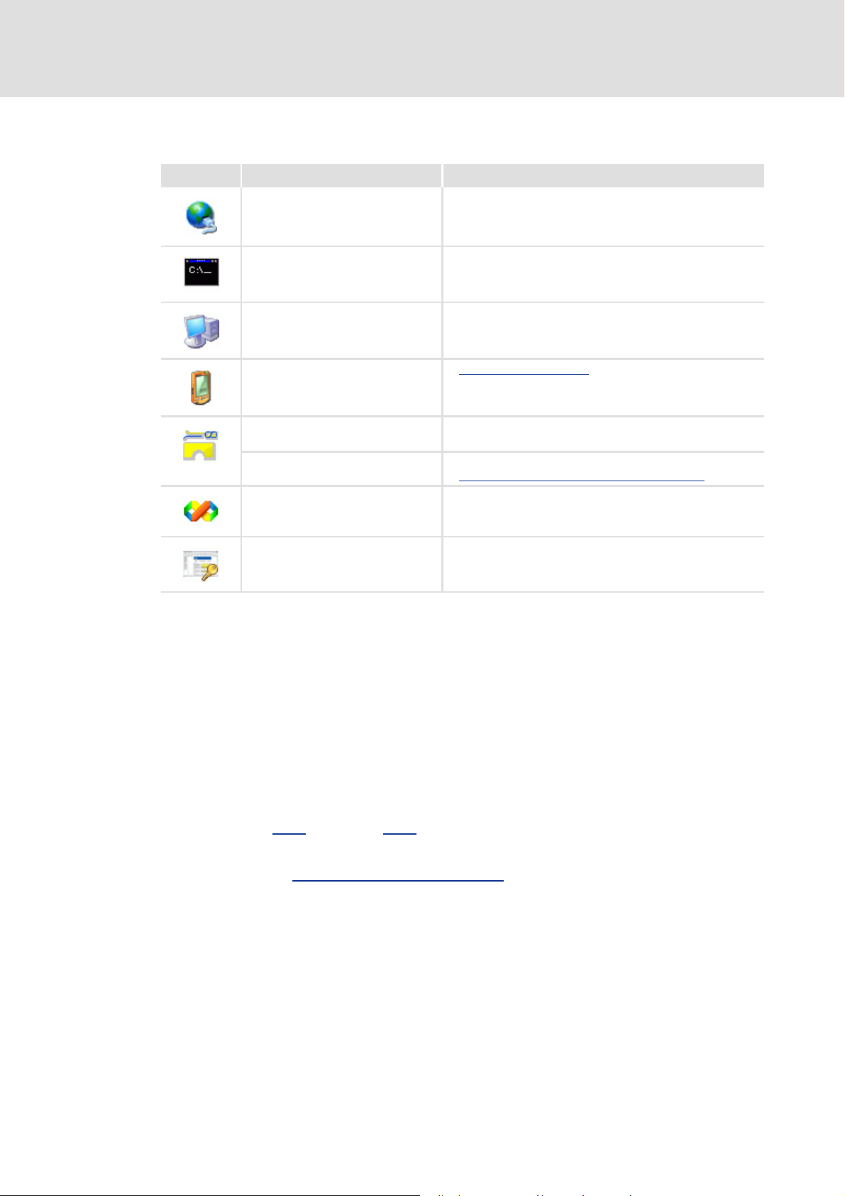
Icon Designation Information
Network Connections Open configuration of the network connections
Service Command Open command line box
System Show system properties
Commissioning
Control elements
Touch Calibration Touch display calibration
»VisiWinNET®« Project Manager Start »VisiWinNET®« Project Manager
• Manage »VisiWinNET®« projects
»VisiWinNET®« Remote Access Start »VisiWinNET®« Remote Access
Transferring an application to the target device
VisualStudio Connect VisualStudio2005 ConManClient
»WebConfig« Start »WebConfig«
( 31)
Function key "F2"
Standard mode: The key sends the key code for <SHIFT>+<F2>
The standard assignment of the function key is the right mouse-click.
Service mode: The screen brightness is increased.
Function key "F3"
Standard mode: The key sends the key code for <SHIFT>+<F3>
( 116)
Service mode: The screen brightness is reduced.
The codes C422
(C0422) and C423 (C0423) contain the parameters for screen brightness.
Further information on the codes containing the values of the screen brightness can be
found in chapter Parameters of standard devices
( 129)
Shift key ""
Standard mode: The key sends the key code for <SHIFT>+<F4>.
The shift key activates the Service mode. When the system is started, the shift key
interrupts batch processing and executes the
Windows® CE control panel.
2.5 EN - 01/2012 L 25
Page 26
Industrial PC | Parameter setting & configuration
Commissioning
Control elements
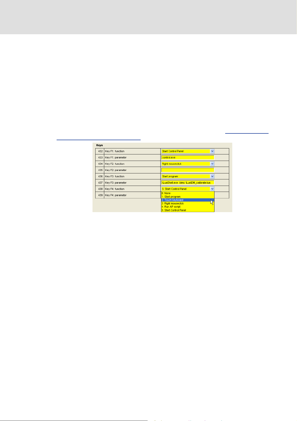
4.2.3 Changing the function key assignment in the »WebConfig«
The assignment of the function keys of the panel can be configured via the
»WebConfig«.
Each function key can be assigned with different functions via a selection list:
–The Start program option enables linking a function key to the start of an
application,
– Touch keyboard assigns the function key to the on-screen keyboard,
– Right mouse-click assigns the function key with the right mouse-click,
– Run AP script starts an automation panel script,
– Start control panel starts the Windows® CE control panel.
The function key assignment can be changed via the Panel button. Parameters of the
standard device of the Industrial PC ( 51)
[4-2] Representation of the function key assignment as a list field (example: the F4 key)
26 L 2.5 EN - 01/2012
Page 27
Industrial PC | Parameter setting & configuration
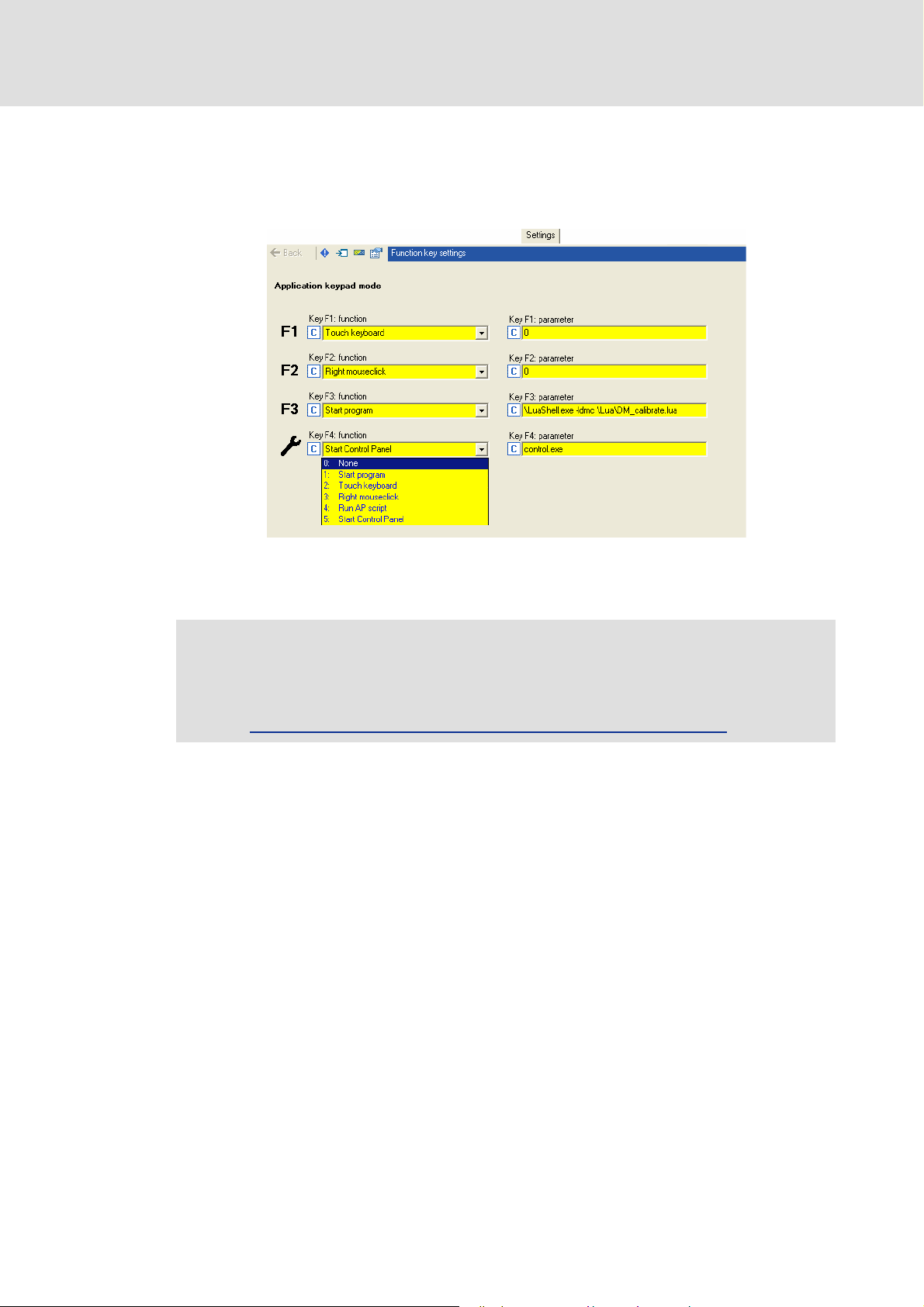
4.2.4 Changing the function key assignment in the L-force »Engineer«
The panel function key assignment can be configured in the »Engineer«.
Every function key has a selection list including different function assignments.
Commissioning
Control elements
[4-3] Function key assignment in the L-force »Engineer« with an online connection to the Industrial PC
Note!
The function key assignment can only be changed if an online connection to the
Industrial PC has been established.
Online connection between the Engineering PC and Industrial PC
( 45)
2.5 EN - 01/2012 L 27
Page 28
Industrial PC | Parameter setting & configuration
Commissioning
Control elements
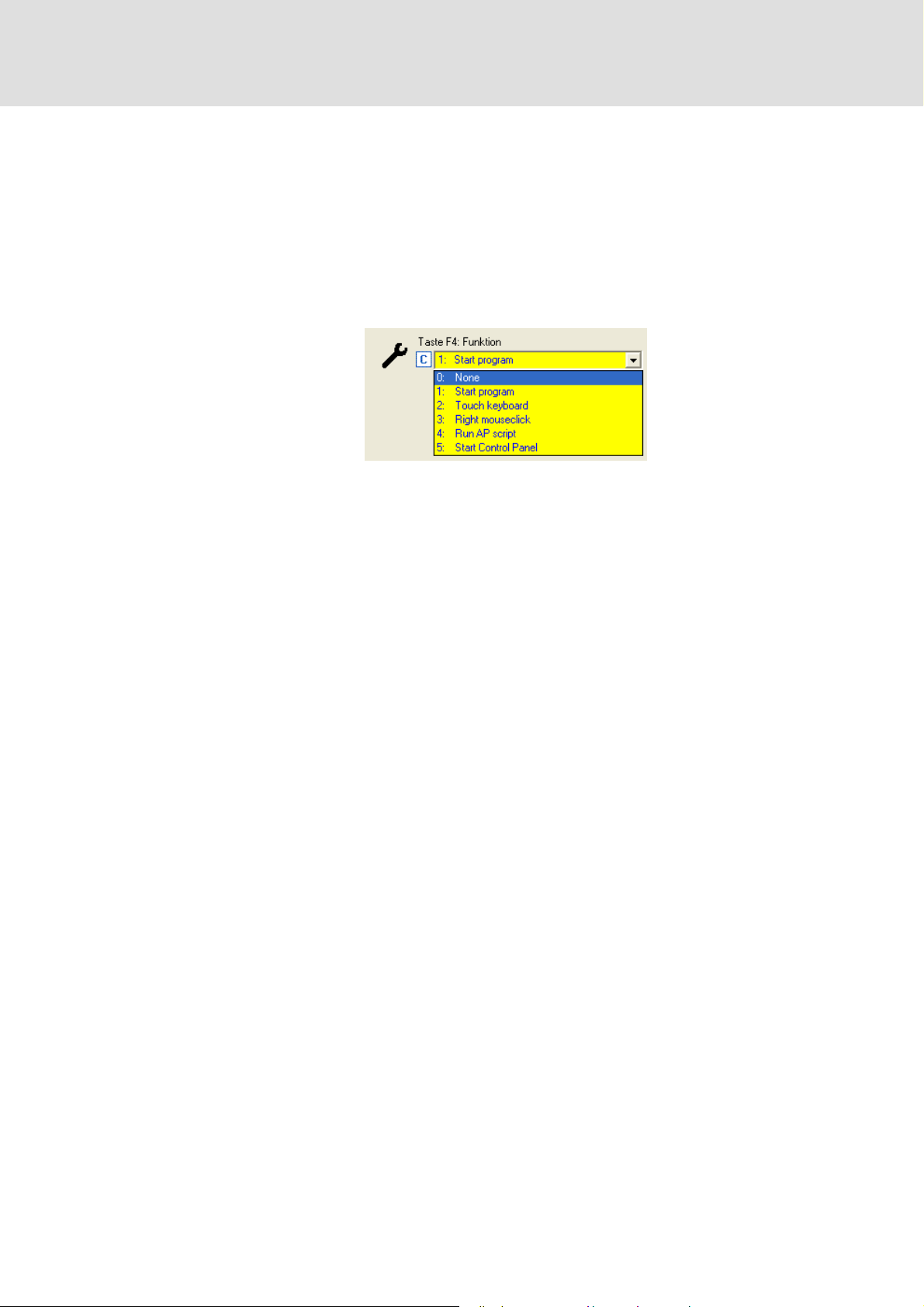
How to start the function key assignment in the »Engineer«:
1. Highlight the corresponding Industrial PC in the project view.
2. Establish the online connection to the Industrial PC selected.
• Observe the chapter "Establishing the online connection to an Industrial PC" in
the »Engineer« documentation.
3. Click the Settings tab.
For every function key a selection list with different functions is available:
–The Start program option enables linking a function key to the start of an
application,
– Touch keyboard assigns the function key to the on-screen keyboard,
– Right mouse-click assigns the function key with the right mouse-click,
– Run AP script starts an automation panel script,
– Start control panel starts the Windows® CE control panel.
Alternatively the function key assignments can also be configured via codes C432 to
C439.
28 L 2.5 EN - 01/2012
Page 29

4.3 System boot-up
Note!
Removing the CF card causes a failure of the system! The CF card is required for
the system start, as the operating system and all the system files required for the
boot process are stored on the CF card.
The CF card is the storage medium of the Industrial PC.
During the system start-up, the Industrial PC generates the required data in the main
memory from the data bases of the CF card. Thus the Industrial PC can only be operated
in connection with the CF card.
Configurations which have been saved previously, e.g. the entry of the IP address and
the touch calibration, are taken into account for the system start.
Industrial PC | Parameter setting & configuration
Commissioning
Technical background information
4.4 Technical background information
4.4.1 Data management
During a system start the data management generates the required
registry entries from the reference data saved. As the registry is not saved with mains
failure protection, the Industrial PC regenerates the registry at every system start.
The reference data base is composed of the IPC data and parameters which are saved
to the files of the data manager. The remaining data are stored within the databases
by the Industrial PC. The CF card serves as a storage medium for saved data.
4.4.2 Starting process
The operating system is stored in a binary file on the CF card. During system start-up the
Industrial PC loads the system data and starts the operating system. The Industrial PC
executes the following steps during a start-up:
1. Loading the system data from the binary file into the main memory and starting the
operating system:
2. Unpacking the system programs and installing the device drivers:
– Unpacking of the basic settings from the database,
– Installation of the "backup and restore“ components,
– Installation of the device scanner,
– Installation of the data manager.
After unpacking the system files, the Industrial PC starts the system programs. The device
scanner identifies the IPC configuration and establishes the topological addressing.
2.5 EN - 01/2012 L 29
Page 30

Industrial PC | Parameter setting & configuration
Commissioning
Configuring the Industrial PC
Note!
• The Industrial PCs are preconfiured, i.e. during initial commissioning the
touch display is already calibrated and a default IP address (192.168.5.99) is
defined.
• After 15 seconds the network configuration and the touch calibration are
closed automatically, and the Industrial PC continues to boot.
The preset IP configurations can be configured using the »Engineer« and »WebConfig«.
Entering the IP address of the Industrial PC
4.5 Configuring the Industrial PC
This chapter will inform you on how to configure the Industrial PC during initial
commissioning. The configuration of the IP address and the touch calibration are
maintained when the system is restarted.
( 32)
30 L 2.5 EN - 01/2012
Page 31

4.5.1 Touch display calibration
Tip!
Use a ballpoint pen with retracted cartridge for the touch calibration or a special
PDA/touch pen. In this way the calibration can be carried out more precisely.
Note!
• The touch calibration can be viewed for 15 seconds. Then the touch display
remains in an uncalibrated state so that the touch function does not properly
work. When the system is started again, the Industrial PC carries out another
touch calibration.
• The touch calibration can be started manually:
– Via one of the function keys, standard setting <F3>,
–In the Windows® CE control panel on the IPC Control panel
Industrial PC | Parameter setting & configuration
Commissioning
Configuring the Industrial PC
( 25)
Touch calibration is required if...
...you replace the CF card,
...you have updated the IPC software,
...a USB data carrier with backup / restore configuration has been connected,
...the Industrial PC remains in the service mode due to start-up problems,
...the Industrial PC detects a change in the hardware configuration when the system is
started.
How to calibrate the touch display:
1. If the touch calibration cannot be viewed, press function key <F3>.
• The icon appears on the screen surface.
2. Press the red-white icon displayed on the screen with your finger, PDA/touchpen,
or similar.
• The icon skips from its initial position to the upper left-hand corner.
2.5 EN - 01/2012 L 31
Page 32

Industrial PC | Parameter setting & configuration
Commissioning
Configuring the Industrial PC
3. Keep the icon pressed.
• The icon gets smaller and after letting go skips to the right upper corner.
4. Repeat step 3 times.
• Until the Accept button appears.
5. Press Accept.
4.5.2 Establishing an automatic dial-up connection
Further information on how to establish an automatic dial-up connection, remote
maintenance and diagnostics options can be found under: Remote maintenance and
diagnostics ( 82)
In order to carry out a remote maintenance on the Industrial PC different mechanisms are
provided:
Remote Access Service (RAS) connection
telnet connection ( 86)
FTP connection ( 88)
4.5.3 Entering the IP address of the Industrial PC
The Industrial PC has the following network settings by default:
Setting Value
IP address 192.168.5.99
Subnetwork 255.255.255.0
Default gateway 192.168.5.1
When the Industrial PC is commissioned for the first time, the desired
IP address must be entered.
( 82)
32 L 2.5 EN - 01/2012
Page 33

Industrial PC | Parameter setting & configuration
4.5.3.1 Industrial PCs with a touch panel/with an external monitor
Tip!
Connect a keyboard to the Industrial PC for entering the IP address. Alternatively
you can start the input panel with the F1 function key on the Industrial PC. Make
your entries afterwards:
[4-1] IP settings of the Industrial PC by default
Start the control panel with <Shift+F4>.
Commissioning
Configuring the Industrial PC
Start the network connections by double-click and enter the IP address, subnet mask,
and the default gateway.
After clicking the button the IP address is saved and need not be entered again
when the system is restarted.
4.5.3.2 Industrial PC without touch panel/without external monitor
If no external monitor is provided, a laptop with a suitable IP address as well as a
subnetwork template and a default gateway are required to carry out the settings. The
preset IP address of the Engineering PC is 192.168.5.100.
Connect the laptop to the Industrial PC by means of a "crossed" network cable.
Change the settings on an HTML compliant browser:
Setting IP addresses
Establish the connection from the laptop to the Industrial PC. For this purpose enter the
IP address of the Industrial PC on the browser: 192.168.5.99 (default setting).
Select the Ethernet button and enter the desired IP address, subnet mask, and the
default gateway of the Industrial PC.
Click Accept & Save all
Set Apply IP configuration to the value "Activate device"
( 45)
Re-click Accept & Save all to save the network settings.
2.5 EN - 01/2012 L 33
Page 34

Industrial PC | Parameter setting & configuration
Commissioning
Configuring the Industrial PC
4.5.4 Establishing Windows® CE access rights
In order to be able to establish a connection to the Industrial PC, each user must be
allocated access rights. For this the respective user has to be set up as a Windows® CE user
with a user name and a password. Windows® CE users can be set up via the »WebConfig«
and the »Engineer«:
Setting up Windows® CE users in the »WebConfig«
Setting up Windows® CE users in the »Engineer« ( 35)
4.5.4.1 Setting up Windows® CE users in the »WebConfig«
Note!
You have to be set up as Windows® CE user to have authorisations for further
services like FTP, telnet, or web server access.
Up to ten Windows® CE users can be set up in the »WebConfig« in the User
management area.
In codes 101 to 169 the user name, password, and various authorisations are set up for
a maximum of ten users.
( 34)
The representation for user 1 is displayed. Users 2 to 10 are represented analogously.
Detailed information on the parameters can be found in the following section:
Parameters of standard devices
34 L 2.5 EN - 01/2012
( 129)
Page 35

Industrial PC | Parameter setting & configuration
4.5.4.2 Setting up Windows® CE users in the »Engineer«
Note!
You have to be set up as a Windows® CE user to be authorised for other services
such as FTP, telnet or web server access. For the actual access you additionally
have to be registered. The assigned user passwords are unencrypted!
In the »Engineer« you can set up to ten Windows® CE users.
The value for code C100 shows the number of users set up.
In codes C101 to C170 you set up the user name, password, and different
authorisations for the users.
Commissioning
Configuring the Industrial PC
2.5 EN - 01/2012 L 35
Page 36

Industrial PC | Parameter setting & configuration
System structure
Engineering PC
5 System structure
This chapter gives you an overview of the general system structure in control technology.
Further information can be found in the respective documentation of the
corresponding Engineering software.
5.1 Engineering PC
The Engineering PC serves to:
– parameterise, configure and maintain the IPC: »WebConfig«, »Engineer«),
– parameterise, configure, and maintain the field devices connected
(»Engineer«, »Global Drive Control«),
– program the IPC (»PLC Designer«),
– creating a visualisation project (»VisiWinNET®«)
– the backup/restore preparation with »IPC Backup & Restore«.
5.2 Industrial PC
The following programs run on the Industrial PC:
– the control software (L-force Logic, L-force Motion),
– the fieldbus drivers,
– the optional visualisation software, and
– additional services (data manager, web server, logbook).
36 L 2.5 EN - 01/2012
Page 37

5.2.1 Centralised control system
The PLC of the Industrial PC (Logic/Motion) is the central control component, consisting
of the PLC runtime program with the running PLC application.
– Via the data manager and the fieldbus driver the PLC (Logic/Motion) has access to
the system components and field devices.
Industrial PC | Parameter setting & configuration
System structure
Industrial PC
[5-1] * The PROFIBUS fieldbus driver can only be accessed via PLC (Logic/Motion). Access via Engineer, GDC or VisiWinNET®
Runtime is not provided.
Field devices and the Industrial PC compose the machine to be commissioned by the
Engineering PC.
The Industrial PC can read parameters from and write parameters to the connected
field devices via the fieldbus (Logic/Motion).
5.2.2 IPC data manager
With the Data manager, Lenze Industrial PCs contain a central tool for the configuration
and data management of a system.
A system in this connection is the combination of an Industrial PC and the field devices
connected to it and registered via the fieldbus.
2.5 EN - 01/2012 L 37
Page 38

Industrial PC | Parameter setting & configuration
Parameterisation using the L-force »Engineer«
Parameterisation via codes
6 Parameterisation using the L-force »Engineer«
This chapter provides information on how to configure the Industrial PC using the
L-force »Engineer«. Further information on the settings in the »Engineer« is provided in the
corresponding topics of the online help.
6.1 Parameterisation via codes
All settings by means of which you parameterise the Industrial PC are summarised in a
parameter list that is numbered serially. The individual entries of this list are called
"codes". Each code can be addressed via a number.
Codes can also contain subparameters. They are also numbered and can be addressed
via a subindex. With the code number and the subindex you can address each
parameter unambiguously.
Tip!
In addition to the parameterisation via the »Engineer«,
you can also parameterise the Industrial PC by means of the »WebConfig«.
The web-based parameterisation can be found in the chapter
Web-based parameterisation with »WebConfig«
( 44)
The parameter lists can be found in the chapters entitled
Parameter reference
38 L 2.5 EN - 01/2012
( 125)
Page 39

Industrial PC | Parameter setting & configuration
6.2 Addressing structure in the »Engineer«
In order to be able to address the individual components, the »Engineer« maps the
complete Industrial PC in a linear code range. Each parameter is listed in a code which can
either be changed or can only be read. The length of the code list depends on the
corresponding hardware assembly.
The basic IPC device uses the code range from 0 to 200;
The Ethernet on board interface uses the code range
from 220 to 260;
The optional panel uses the code range from 400 to 600;
The PLC (Motion/Logic) uses the code range from 600 to 800;
If optional extension modules are used, the code range is extended accordingly. Every
extension module is provided with the card and the interface parameters;
A card plugged into a slot is equipped with one or more interfaces. If a card is plugged
into a slot, the code range is extended accordingly:
Parameterisation using the L-force »Engineer«
Addressing structure in the »Engineer«
The parameters of the extension modules use a maximum of 500 parameters each. The
code number range depends on the slot:
– Slot 1 uses codes 1000 to 1499,
– Slot 2 uses codes 1500 to 1999.
2.5 EN - 01/2012 L 39
Page 40

Industrial PC | Parameter setting & configuration
Parameterisation using the L-force »Engineer«
Addressing structure in the »Engineer«
6.2.1 Volatile data of an »Engineer« project
During operation, the Industrial PC manages the data in the main memory. Since the main
memory is a volatile memory, all information which has not been saved permanently on
the CF card will be lost in the case of a restart.
Changes on individual codes, which are carried out online with the »Engineer« for instance
are volatile data.
Tip!
An existing online connection is indicated in the »Engineer« by an animated icon
below the project view bar:
Note!
Detailed information on the use of the »Engineer« software can be found in the
corresponding »Engineer« documentation.
The settings that you carry out in an
»Engineer« project during an online connection is established remain volatile at first.
– If changes carried out with regard to individual parameters during the online
connection was established are incorrect, the last stable status can be retrieved by
restarting the Industrial PC and the changes can be carried out again.
Manual data backup is possible for saving the current settings permanently.
40 L 2.5 EN - 01/2012
Page 41

6.2.2 Saving data permanently
Code 18 enables you to transmit commands. A command overview can be found in the
description of code 18 of the parameter lists.
Via the Persist all command you can permanently save the changes carried out with an
online connection.
– The complete changes since the last restart of the Industrial PC are persistent.
The Industrial PC stores the data saved manually by the user on the CF card. For the project
management within the Industrial PC, different device commands are available, which can
be activated via code 18.
Industrial PC | Parameter setting & configuration
Parameterisation using the L-force »Engineer«
Parameter reference
When an online connection has been established, you can use the »Engineer« to
activate a device command by selecting it from the Device commands tab in C00018.
6.3 Parameter reference
The codes are numbered and marked in the documentation by a "C" in front of the code,
e.g. "C00002".
For the sake of clarity, some codes contain "subcodes" for storing parameters. This
documentation uses a slash "/" as a separator between code and subcode, e.g.
"C00118/3".
The All parameters tab shows all available codes for parameterising the Industrial PC.
2.5 EN - 01/2012 L 41
Page 42

Industrial PC | Parameter setting & configuration
Parameterisation using the L-force »Engineer«
Representation of the parameters
6.4 Representation of the parameters
6.4.1 Parameters with read access
The »Engineer« displays the parameters with read access with a grey background or,
when an online connection has been established, with a pale yellow background:
6.4.2 Parameters with write access
Input values outside the valid setting range are represented in red font by the
»Engineer«.
6.4.2.1 Parameters with a setting range
In the »Engineer« parameters are set by entering the desired value into the input field
or by means of the two arrow buttons:
The two arrow buttons can be used to increase/decrease the displayed value stepwise.
6.4.2.2 Parameters with a selection list
In the »Engineer« the parameters can be changed via a selection list:
42 L 2.5 EN - 01/2012
Page 43

Industrial PC | Parameter setting & configuration
6.4.2.3 Parameters with a bit-coded setting
The »Engineer« uses a dialog box for the parameter setting in which the individual bits
can be set or reset. Alternatively, the value can be entered as a decimal or hexadecimal
value:
Parameterisation using the L-force »Engineer«
Representation of the parameters
6.4.2.4 Parameters with subcodes
In the »Engineer« parameter list each subcode is itemised individually.
2.5 EN - 01/2012 L 43
Page 44

Industrial PC | Parameter setting & configuration
Web-based parameterisation with »WebConfig«
Parameterisation via codes
7 Web-based parameterisation with »WebConfig«
This chapter provides information on the parameterisation of the Industrial PC using webbased parameterisation.
7.1 Parameterisation via codes
All settings by means of which you parameterise the Industrial PC are summarised in a
parameter list that is numbered serially. The individual entries of this list are called "codes".
Each code can be addressed via a number.
Codes can also contain subparameters. They are also numbered and can be addressed via
a subindex. With the code number and the subindex you can address each parameter
unambiguously.
The web-based parameterisation can be carried out LOCALLY on the Industrial PC or
REMOTELY via http by each Engineering PC transmitted which can be reached via the
network. The Engineering PC is a workplace PC including the Windows® XP operating
system.
Tip!
The web server and the »WebConfig« for the web-based parameterisation are
preinstalled on the Industrial PC.
Parameterisation with the »Engineer« can be found in the chapter
Parameterisation using the L-force »Engineer«
44 L 2.5 EN - 01/2012
( 38)
Page 45

Industrial PC | Parameter setting & configuration
Web-based parameterisation with »WebConfig«
Requirements for working with the web-based parameterisation
The parameter lists can be found in the chapter entitled: Parameter reference ( 125)
7.2 Requirements for working with the web-based parameterisation
This chapter provides you with information on how to prepare a remote connection for the
web-based parameterisation.
7.2.1 Online connection between the Engineering PC and Industrial PC
Connect the Engineering PC directly to the Industrial PC using a network cable.
or
Connect the Industrial PC to the network to which the Engineering PC has access.
Note!
In the case of a direct connection between the Engineering PC and the Industrial
PC, a crossed network cable is required.
The settings of the static IP address of the Engineering PC are only to be carried
out for the direct connection between the Engineering PC and Industrial PC.
7.2.2 Setting IP addresses
Note!
Recommended setting for the Engineering PC:
IP address: <192.168.5.100>
Default setting of the Industrial PC:
IP address: <192.168.5.99>, subnetwork <255.255.255.0>.
Setting for the direct connection between the Engineering PC and Industrial PC:
How to set the static IP address of the Engineering PC:
1. Open the Network connections dialog box Network connections.
(StartSettingsNetwork connections)
2. Select the network interface the Industrial PC is connected to.
Right-click Properties.
3. Select Internet protocol (TCP/IP).
4. Click the Properties button.
5. Select the Alternative configuration tab.
2.5 EN - 01/2012 L 45
Page 46

Industrial PC | Parameter setting & configuration
Web-based parameterisation with »WebConfig«
Requirements for working with the web-based parameterisation
6. Select the User configured option.
• Enter the IP address of the Industrial PC (default address: <192.168.5.99>).
• Enter the subnet mask of the Engineering PC
(standard setting: <255.255.255.0>)
7. Close the individual dialog windows with OK or Close
The Properties of internet protocol (TCP/IP) dialog window
How to set the browser:
1. Open the browser at the Engineering PC
(This setting refers to the Microsoft Internet Explorer).
2. Select the Proxy settings dialog window
(ToolsInternet options ConnectionsSettingsAdvanced)
3. Position the cursor in the Exceptions field at the end of the entries available.
4. Enter the IP address of the Industrial PC:
<;172.31.217*> (example of the IP address of an Industrial PC, default address:
<192.168.5.99>)
5. Close the individual dialog windows with OK.
46 L 2.5 EN - 01/2012
Page 47

Industrial PC | Parameter setting & configuration
7.3 Start of the web-based parameterisation
7.3.1 Start at the Engineering PC
Start a browser at the Engineering PC and enter the IP address of the Industrial PC.
– The dialog box for entering the connection data appears:
Web-based parameterisation with »WebConfig«
Start of the web-based parameterisation
.
1. Enter<User name:password>. As default setting, admin:admin is preselected. Any user
set up on the Industrial PC can log in. User management
2. Confirm with OK .
3. Afterwards the user interface of the web-based parameterisation appears.
User interface
7.3.2 Start at the Industrial PC
After connection to the current supply, the Industrial PC starts automatically. If no external
keyboard has been connected, the on-screen keyboard can be shown via the function key
<F1>.
Change to <Shift+F4> in the Control Panel.
( 49)
( 55)
2.5 EN - 01/2012 L 47
Page 48

Industrial PC | Parameter setting & configuration
Web-based parameterisation with »WebConfig«
Start of the web-based parameterisation
Double-click the WebConfig icon:
1. Enter <User name:password> in the Enter Network Password dialog box . As standard
setting admin:admin is preselected. Every registered user can log in.
2. Confirm with OK .
3. Afterwards the user interface of the web-based parameterisation appears.
User interface
( 49)
.
48 L 2.5 EN - 01/2012
Page 49

7.4 User interface
Industrial PC | Parameter setting & configuration
Web-based parameterisation with »WebConfig«
User interface
The user interface of the »WebConfig« is divided into the following areas
- :
Note!
The representation of the user interface in area depends on the respective
system configuration! The example shows an Industrial PC including the
following extension cards: MC-ETC in slot 1 and MC-CAN2 in slot 2.
2.5 EN - 01/2012 L 49
Page 50

Industrial PC | Parameter setting & configuration
Web-based parameterisation with »WebConfig«
User interface
Area Information
Menu buttons Parameters of the standard device of the Industrial PC
• Parameter list 1: All parameters of the standard device
• Parameter list 2: All parameters of the installed extension cards
• PLC parameters
• Ethernet (on board) parameters
•Panel parameters
Diagnostics/Command execution
• Logbook parameters
• Logbook of the Industrial PC
• Device commands
•Remote control
User management
• Setting users 1-10
General parameters
•Time
•UPS settings
• Monitoring functions
•Memory
• Identification
Extension card parameters
( 55)
( 56)
( 52)
( 56)
( 51)
Note:
• The represented parameters of slots 1 and 2 depend on the corresponding extension
modules that are installed!
• The additional buttons for the actually installed extension cards are automatically
added to the menu buttons.
• The top-down order of the buttons corresponds to the order in which the extension
Buttons Parameter list buttons
Display area Parameter display
cards have been installed (slot 1, slot 2).
• In the following section, the parameters of the communication cards are listed in
numerically ascending order: Industrial PC extension modules
Polling
Language selection
( 58)
( 58)
( 58)
Depending on the selected menu button, the parameters can be viewed in this area.
• Code numbers
• Name of the code
• Representation of the display, entry, selection, control and list fields.
( 161)
According to the equipment of the Industrial PC, deviating components are shown by use
of the menu control fields.
Detailed information on the parameters can be found in the section entitledParameter
reference ( 125)
50 L 2.5 EN - 01/2012
Page 51

Industrial PC | Parameter setting & configuration
Web-based parameterisation with »WebConfig«
User interface
Representation of parameter values
In the display area of the web-based parameterisation, settings of device parameters are
represented with different background colours which have the following meaning:
Colour Example Meaning
Pale yellow Parameter (read only)
• Display of status information and actual values.
Yellow Parameter (read and write)
• The current parameter value of the device is displayed. Changes with regard to a
parameter have to be transmitted to the device with Submit or Submit & Persist
all.
Red Entry of a value beyond the valid range.
•Via Refresh the original value is shown again.
• A correct value can be entered in the red input field and transmitted to the device
with Submit or Submit & Persist All.
In the following the individual menus of the web-based parameterisation »WebConfig«
are described.
7.4.1 Parameters of the standard device of the Industrial PC
Button Function
Displays all parameters of the standard device of the Industrial PC in
numerically ascending order.
• This user interface helps you to e.g.
–Find system properties and version numbers (read-only parameters),
–Set the system time,
–Activate the USB connection at the front of the monitor panel.
Parameters of standard devices
The other menu buttons of areas , and are a filtered view of parameter
list 1.
Displays all parameters of the installed extension cards in numerically
ascending order.
• The parameters of the extension cards are listed according to the order in
which they have been installed.
Extension card parameters
The other menu buttons of area are a filtered view of parameter list 2.
Displays the PLC parameters in numerically ascending order.
• This user interface shows you e.g.
–The PLC status,
–Information on a PLC project.
PLC (Logic/Motion)
Displays the Ethernet (on board) parameters in numerically ascending order.
• On this user interface the network settings of the on board
network connection are displayed/set.
Ethernet interface (on board)
Displays the panel parameters in numerically ascending order.
• This user interface helps you setting the settings for the monitor panel
and the function keys. Here you can e.g.
–Change the brightness of the monitor panel,
–Edit the parameters of the F1 to F4 function keys.
Panel
( 155)
Further information on the parameterisation of the function keys:
Commissioning
( 51)
( 19)
( 129)
( 56)
( 153)
2.5 EN - 01/2012 L 51
Page 52

Industrial PC | Parameter setting & configuration
Web-based parameterisation with »WebConfig«
User interface
7.4.2 Diagnostics/Command execution
Button Function
Displays parameters of the following areas:
•Diagnostics
•Logbook
In the Logbook area you can configure settings regarding the Logbook.
Further information on remote maintenance options
of the Industrial PC:
Remote maintenance and diagnostics
Displays logbook contents.
• Different filter settings display, for instance, only the oldest or only the
most recent logbook entries.
Logbook
Displays the commands to be executed of the Industrial PC. The available
commands can be found in the following section in code 18 (C0018
Parameters of standard devices
Displays the following parameters for remote control purposes of the
Industrial PC:
( 53)
( 82)
)
( 129)
•RAS settings
RAS settings with the web-based parameterisation
•FTP settings
FTP settings with the web-based parameterisation
•Telnet settings
Settings of the web-based parameterisation
Information on the parameters can be found in the following section:
Parameters of standard devices
( 129)
( 84)
( 88)
( 86)
52 L 2.5 EN - 01/2012
Page 53

7.4.3 Logbook
This user interface displays the logbook of the Industrial PC. The logbook provides various
filter options to show specific logbook contents.
Note!
Industrial PC | Parameter setting & configuration
Web-based parameterisation with »WebConfig«
User interface
If the ClearLog button is clicked, the entire logbook contents of the Industrial PC
are deleted without further query!
7.4.3.1 Explanations of the logbook entries, example
Logbook entry, example Meaning
00001 Consecutive number of the entry
2009-03-24 14:45:26 Date(Format: Year-Month-Day)/Time on the Industrial PC when
the logbook entry was made
Log service Application that has triggered the entry (application)
Logbook cleared Description of the event
Continuous processing Event origin within the application (area)
Warning Severity of the event
ü
2.5 EN - 01/2012 L 53
Page 54

Industrial PC | Parameter setting & configuration
Web-based parameterisation with »WebConfig«
User interface
7.4.3.2 Filter options
Section Information
Logbook Display logbook entries
Explanations of the logbook entries, example
Time period Select filter for the time period of the logbook entries shown
• The logbook will only display entries which are in the selected time
period.
Application Set filter for the application
• The logbook will only display entries for the selected applications.
Severity Set filter for the severity of the error messages displayed
• The logbook will only display entries that correspond to the selected
degree of severity.
Area Set filter for the origin of the event
• The logbook will only display entries that correspond to the selected area.
7.4.3.3 Time filter for the display of logbook entries
( 53)
Area Filter option Function
Time period 1: All Display all entries
-from Time zone: Date (Format: Year/
-to Time zone: Date (Format: Year/
-last 1: Days
2: From - to Filter entries according to date
3: Last Display last entries only. Possible
Month/Day), Time (Format: Hours/
Minutes/Seconds)
Example:
10th March 2009, 15.05 hours, 11
seconds: UTC 2009 03 10 15 05 11
Month/Day), Time (Format: )
2: Weeks
3: Months
4: Years
specified
filter options:
•1: Days
• 2: Weeks
• 3: Months
•4: Years
Date specification for filtering the
entries to be displayed
• Starting date from which the
entries are to be displayed
Date specification for filtering the
entries to be displayed
• Target date up to which the
entries are to be displayed
Display entries according to filter
options.
• To activate this filter option, in the
Time period area of the selection
list the last item m ust be se lect ed!
54 L 2.5 EN - 01/2012
Page 55

7.4.3.4 Export logbook entries
How to export logbook entries into a text file (without using the »Engineer«):
1. Establish an online connection to the Industrial PC. Entering the IP address of the
Industrial PC ( 32)
2. The Logbook tab displays the available entries of the logbook.
3. Click the ExportLog button in the header of the logbook to export the logbook
entries into a file.
The contents of the logbook is exported into a German file (_de) and English file
(_en) to the CF card into the \Storage\export\log directory (the directory has
already been set by default on the CF card).
• Note: The contents of the logbook can additionally be exported to a USB flash
drive (connected to the IPC). In order to be able to export the contents of the
logbook to the USB flash drive, the \export\log directory has to be set
manually onto the USB flash drive.
• When the ExportLog button is clicked, the IPC writes the contents of the
logbook to the CF card and into the USB flash drive (directory \export\log).
Industrial PC | Parameter setting & configuration
Web-based parameterisation with »WebConfig«
User interface
The execution of an ExportLog is entered into the logbook as Information. (Entries of
the Information type can only been seen in the logbook if the corresponding filter
option is set in the Logbook).
Export logbook entries via device command
The start of the logbook export can also be activated by writing the command code C18 via
the PLC or via »VisiWinNET®«.
Go to the Device command section (code 18) and execute the command 304: Export
complete logbook to export the logbook entries.
7.4.4 Device commands
In this area, the available device command of code 18 (
Code 19 (
command.
More information on the supported device commands can be found in the following
section: Parameters of standard devices
7.4.5 User management
C0019)displays status information regarding the executed
C0018)can be executed.
( 129)
This section sets up the Windows® CE users (users 1-10) and defines their access
authorisations.
Button Function
Set up Windows
• Enter user name and password, and the home directory.
• Enter access authorisation of the user.
Standard value for user 1: admin:admin
2.5 EN - 01/2012 L 55
® CE user, enter user-specific data
Page 56

Industrial PC | Parameter setting & configuration
Web-based parameterisation with »WebConfig«
User interface
7.4.6 General parameters
Button Function
Displays the parameters for setting the time, date, system time, and time
zone.
Displays the UPS settings for the parameterisation of optional
UPS accessories.
Displays hardware/temperature data.
Displays information on program/Flash memories.
Displays information on system identification.
7.4.7 Extension card parameters
This area of the »WebConfig« gives on overview of the parameters of the installed
extension cards. The Industrial PC is able to support a maximum of two communication
cards at the same time. The following communication cards can be applied:
MC-CAN2,
MC-ETC,
MC-PBM,
MC-ETH.
A distinction is drawn between:
– Interface parameters,
– Communication card parameters.
A communication card can be equipped with several physical bus interfaces, such as the
MC-CAN2 communication card.
CAN communication card (MC-CAN2)
EtherCAT communication card (MC-ETC) ( 172)
PROFIBUS master communication card (MC-PBM) ( 207)
Ethernet communication card (MC-ETH) ( 209)
( 162)
56 L 2.5 EN - 01/2012
Page 57

Industrial PC | Parameter setting & configuration
7.4.7.1 CAN communication card (MC-CAN2)
Note!
The parameters can only be viewed if the corresponding MC-CAN2
communication card is inserted. Two communication cards per IPC can be
plugged in maximally!
Button Function
The MC-CAN2 button displays the parameter list of the MC-CAN2
communication card.
Web-based parameterisation with »WebConfig«
User interface
MC-CAN2 interface x Parameters of the x interface of the
MC-CAN2 communication card
•The MC-CAN2 Interface x button displays the parameters of the
respective interface (1 or 2) of a MC-CAN2 communication card.
• In addition, the button displays which card the respective interface
belongs to.
• The parameters of the communication card are listed in the following
section in numerically ascending order:
CAN communication card (MC-CAN2)
7.4.7.2 EtherCAT communication card (MC-ETC)
This user interface displays the parameters of the MC-ETC communication card. An
Industrial PC can maximally have one MC-ETC card!
Note!
The parameters can only be viewed if the corresponding MC-ETC
communication card has been installed!
Button Function
Display parameters of the MC-ETC EtherCAT communication card
• The parameters of the communication card are listed in the following
section in numerically ascending order:
EtherCAT communication card (MC-ETC)
Display interface parameters of the MC-ETC EtherCAT communication card
• This user interface displays the interface parameters of the EtherCAT
communication card.
Display master settings of the MC-ETC EtherCAT communication card
• On this user interface the parameters of the EtherCAT master are set or
displayed.
Parameters of the EtherCAT master
• This user interface sets and displays the statistics of the EtherCAT master.
( 162)
( 172)
Parameters of the EtherCAT slaves
• This user interface sets and displays the parameters of the EtherCAT
slaves.
• After pressing the button, the information of the first slave can be
viewed. In order to display the information of another slave the desired
node address must be entered in 1095.2.
2.5 EN - 01/2012 L 57
Page 58

Industrial PC | Parameter setting & configuration
Web-based parameterisation with »WebConfig«
User interface
7.4.7.3 PROFIBUS master communication card (MC-PBM)
Button Function
Display the parameters of the PROFIBUS master card.
• This user interface displays the parameters of the MC-PBM
communication card.
• The parameters of the communication card are listed in the following
section in numerically ascending order:
PROFIBUS master communication card (MC-PBM)
7.4.7.4 Ethernet communication card (MC-ETH)
Button Function
Display the parameters of the Ethernet communication card.
• The parameters of the communication card are listed in the following
section in numerically ascending order:
Ethernet communication card (MC-ETH)
Display the address parameters of the Ethernet communication card.
( 207)
( 209)
7.4.8 Polling
In this menu the polling of the screen is activated.
7.4.9 Language selection
In the Language section you can define the desired language settings from the
selection list.
The language settings take immediate effect, the »WebConfig« does not need to be
restarted.
7.4.10 Parameter list buttons
Button Function
Accept Accept data.
Accept & Save all Accept and save all changed data.
Update Reload data and update screen display
Interval:
Setting the interval for the polling in seconds.
• Example value: 5.
Active:
Click the control field to activate the polling.
• After a system restart changed data are lost, as they are not persisted
automatically.
• The data will remain on your PC after a system restart.
58 L 2.5 EN - 01/2012
Page 59

Industrial PC | Parameter setting & configuration
8 Programming with the »PLC Designer«
This chapter provides you with information on the programming of the control function of
the Industrial PC.
Further information on working with the »PLC Designer« can be found in the
documentation for the »PLC Designer«.
8.1 Basics
The »PLC Designer« is the PLC programming system to be installed on the Engineering PC.
The »PLC Designer« is one of the Lenze Engineering tools. The »PLC Designer« accesses the
IPC via Ethernet:
Programming with the »PLC Designer«
Basics
The »PLC Designer« serves to create PLC programs in the programming languages of IEC
61131. The IEC 61131 programming languages are:
Instruction list (IL),
Ladder diagram (LD),
Function plan (FP),
Structured text (ST),
Sequential function chart (SFC),
Function block diagram (FBD).
2.5 EN - 01/2012 L 59
Page 60

Industrial PC | Parameter setting & configuration
Programming with the »PLC Designer«
Configuration and parameterisation via the control application
The completely created and compiled program is transferred to the Industrial PC with the
»PLC Designer«. On the Industrial PC the program can be executed by the
L-force Logic & Motion runtime software.
8.2 Configuration and parameterisation via the control application
For creating the control application diverse function blocks, like for example standardised
libraries with motion functions according to PLCopen, are provided.
Furthermore there are function blocks that are suitable for the access to parameters of the
Industrial PC.
The translated PLC program is loaded into the Industrial PC via the network by means of
the »PLC Designer«. There it can be processed by the operating software of the Industrial
PC.
Further information on working with the »PLC Designer« can be found in the
documentation for the »PLC Designer«.
60 L 2.5 EN - 01/2012
Page 61

Industrial PC | Parameter setting & configuration
8.3 Accessing IPC parameters from the PLC
For the parameter access to parameters of the Industrial PC from the PLC an interface to
the PLC is provided by means of the PLCDataManagerAccess library.
8.3.1 The LDM_ParameterAccess_FB function block
Function library: PLCDataManagerAccess
With the LDM_ParameterAccess_FB function block the device parameters of the Industrial
PC can be read and written by the PLC.
LDM_ParameterAccess_FB
BOOL ⎯ bExecute bDone ⎯ BOOL
LDM_tDIR ⎯ eDirection bBusy ⎯ BOOL
STRING(255) ⎯ sTopoAddr bError ⎯ BOOL
WORD ⎯ wCode dwErrorID ⎯ DWORD
WORD ⎯ wIndex eDataRType ⎯ LDM_tVT
BYTE ⎯ bySubIndex sDataR ⎯ STRING (255)
LDM_tVT ⎯ eDataType byDataR ⎯ BYTE
STRING(255) ⎯ sDataW wDataR ⎯ WORD
BYTE ⎯ byDataW dwDataR ⎯ DWORD
WORD ⎯ wDataW
WORD ⎯ dwDataW
Programming with the »PLC Designer«
Accessing IPC parameters from the PLC
Inputs
Identifier/data type Information/possible settings
bExecute
eDirection
LDM_tDIR
sTopoAddr
STRING(255)
wCode
WORD
wIndex
WORD
bySubIndex
eDataType
LDM_tVT
sDataW
STRING(255)
byDataW
Rising edge starts the access
BOOL
Access direction
•LDM_READ - read
•LDM_WRITE - write
Topology address
'/' - access to parameters of the Industrial PC
Code of the parameter (Lenze)
Then wIndex has to be set to 0
Index of the parameter (CANopen)
Then wCode has to be set to 0
Subindex/subcode of the parameter
Byte
Specification of the type of the parameter to be written
Example: LDM_VT_I2 : 2 bytes integer
Example: LDM_VT_I4 : 4 bytes integer
Value to be written (string) - table [8-1]
Value to be written (1*byte) - table [8-1]
Byte
2.5 EN - 01/2012 L 61
Page 62

Industrial PC | Parameter setting & configuration
Programming with the »PLC Designer«
Accessing IPC parameters from the PLC
Identifier/data type Information/possible settings
wDataW
WORD
Value to be written (2*byte) - table [8-1]
dwDataW
WORD
Value to be written (4*byte) - table [8-1]
Outputs
Identifier/data type Value/meaning
bDone
bBusy
bError
dwErrorID
DWORD
eDataRType
LDM_tVT
sDataR
STRING(255)
byDataR
wDataR
WORD
dwDataR
DWORD
TRUE if operation has been completed successfully
BOOL
TRUE as long as the operation is running without errors
BOOL
TRUE if an error has occurred
BOOL
Greater 0 if an error has occurred
Returned type of the parameter read
{LDM_VT_EMPTY, LDM_VT_I4, ...}
Value read (string) - table [8-1]
Value read (1*byte) - table [8-1]
Byte
Value read (2*byte) - table [8-1]
Value read (4*byte) - table [8-1]
Input, output Data type
sDataR, sDataW LDM_VT_BSTR
byDataR, byDataW LDM_VT_I1, LDM_VT_UI1
wDataR, wDataW LDM_VT_I2, LDM_VT_UI2
dwDataR, dwDataW LDM_VT_I4, LDM_VT_UI4, LDM_VT_DATE
[8-1] Connection between the inputs and outputs and the data type
62 L 2.5 EN - 01/2012
Page 63

Industrial PC | Parameter setting & configuration
Programming with the »PLC Designer«
Accessing IPC parameters from the PLC
8.3.2 The LLS_AddLog function block - Generate logbook entry
Function library: PLCLoggingAccess
This function renders it possible to make an entry in the logbook of the Industrial PC.
The function supplies a return value TRUE if the entry was carried out.
LLS_AddLog
T_LLS_Severity ⎯ eSeverity Status ⎯ BOOL
T_LLS_Facility ⎯ eFacility Valid ⎯ BOOL
STRING(80) ⎯ sLogPayLoad Error ⎯ BOOL
Inputs
Identifier/data type Information/possible settings
eSeverity
T_LLS_Severity
eFacility
T_LLS_Facility
sLogPayLoad
STRING(80)
Logging Severity - risk of the error
• LLS_FatalError
•LLS_Error, LLS_Warning
•LLS_Information
The Enum parameter eSeverity (IEC_INT) transferred to Add2Log as severity (BYTE).
Logging Facility: - area from which the error is reported
• LLS_PLC_USER_LOG_SCOPE1
• LLS_PLC_USER_LOG_SCOPE2
• LLS_PLC_USER_LOG_SCOPE3
The Enum parameter eFacility (IEC_INT) is transferred to Add2Log as Facility
(WORD).
Logbook entry
The Ansi string from "sLogPayLoad" is transferred to Add2Log as 1-byte string
parameter. ("hs", SLOGPAYLOAD)
2.5 EN - 01/2012 L 63
Page 64

Industrial PC | Parameter setting & configuration
IPC backup & restore
Introduction to »IPC Backup & Restore«
9IPC backup & restore
This chapter provides information on data backup and restore on the Industrial PC under
Windows® CE.
Furthermore, the device software can be updated via the USB interface. Generally, a
complete update of the device software can be carried out. Individual software packets
cannot be updated.
Further information on the use of »IPC Backup & Restore« can be found in the
documentation of Windows® XP »IPC Backup & Restore«.
9.1 Introduction to »IPC Backup & Restore«
The »IPC Backup & Restore« functionality enables...
...the generation of backups,
...the restore of selected backups,
...the installation of software updates.
The backups can be saved to the storage medium in the form of individual software
packets.
The standard storage medium for Backup & Restore is a USB stick which has been
preconfigured using the »IPC Backup & Restore« Windows® XP software.
Depending on the IPC device type, the user either has to interact or the selected function is
carried out automatically when the system is started.
64 L 2.5 EN - 01/2012
Page 65

Industrial PC | Parameter setting & configuration
Differences between archive, backup and restore
9.2 Differences between archive, backup and restore
Note!
A backup written to the USB stick only contains individual system data!
For creating a complete backup you have to:
• Switch off the IPC,
• Remove the CF card,
• Insert the CF card in a CF card reader,
• Archive the data of the CF card under Windows® XP using »IPC Backup &
Restore«
Archive
An "Archive" is created under Windows® XP using »IPC Backup & Restore« from the CF card.
The term "Archive" defines the contents of a Compact Flash card.
IPC backup & restore
The Compact Flash card...
...contains the complete "memory" of the Industrial PC,
...contains all permanently saved components such as:
– the operating system,
– software,
–data.
A Compact Flash card in an Industrial PC can be compared to the hard disk of an
Engineering PC.
Backup
A "Backup" is created using »IPC Backup & Restore« under Windows® CE.
When a backup is carried out, individual components are copied from the Compact
Flash card to a USB stick.
Restore
A "Restore" of the backup data is carried out using »IPC Backup & Restore« under
Windows® CE.
"Restore" describes the process of restoring backup data from a
USB stick to the Compact Flash card.
A restore for instance is used
– to transfer individual components from one Industrial PC to another IPC,
– to restore individual data if a fault has occurred.
2.5 EN - 01/2012 L 65
Page 66

Industrial PC | Parameter setting & configuration
IPC backup & restore
Function
9.3 Function
The software and the operating system of the Industrial PC are stored on the CF card. With
»IPC Backup & Restore« for Windows® CE you have the possibility of saving data from the
CF card to a USB stick.
A backup created like this can be transferred from the USB stick to the CF card anytime by
restoring the data.
Furthermore a software update from a USB stick can be installed on the CF card of the
Industrial PC by means of »IPC Backup & Restore«.
The entire update process comprises several individual steps and is processed as follows.
Backup of the current system before changes have been carried out, in the following
referred to as Backup_orig.
Migration of the existing databases to the new structure, in the case of a version
change.
Installation of the SW update containing the Lenze software and the operating system.
The update process contains several successive steps; the sequence step is only carried out
if the previous step was carried out successfully. In order to be able to trace this sequencer,
log messages are written throughout the procedure.
The log messages signal the steps that have been carried out.
Update Process
Update required?
Yes
Backup of original
Backup OK?
UPDATE
Update OK?
No No
OK
Yes
MIGRATION
Status
MIGRATION
Failed/rollback OK
Identical version
No
Running/
Rollback failed
Yes
M1
M2
RESTORE
Restore OK?
M3
M4 M8
M5
REBOOT
M7
66 L 2.5 EN - 01/2012
Page 67

Industrial PC | Parameter setting & configuration
IPC backup & restore
Function
The log messages are named from M1 to M7. The following log messages can occur:
Message Message in the logbook Remedy
M1 System version is identical to the
selected update packet. No action
necessary.
M2 Backup finished with <<1>> errors. During the creation of Backup_orig, errors have occurred.
M3 Migration finished successfully.
Update finished with <<1>> errors.
Insert a backup CF card and restore
old system.
M4 Update finished successful The installation of the SW update has been completely
M5 Migration failed. Rollback finished
successful. The system was not
changed. Try Update again.
M6 Migration failed. Restore was
successful. The system was not
changed. Try Update again.
M7 Migration failed
Restore finished with <<1>> errors.
Insert a backup CF card and restore
old system.
The version of the Industrial PC is identical to that of the
update.
• Remove the USB stick or
• Change the control file of the USB stick with
»IPC Backup & Restore« under Windows® XP.
The update process cannot be continued.
• You can continue using the existing system, or you can try
again.
The migration of the databases has been carried out
successfully, but the installation of the update has failed.
Try the following:
• Establish an existing archive on your Compact Flash card.
• Then you can restore Backup_orig from the USB stick to
receive the original state.
carried out successfully.
The migration of the databases has failed. The attempt to
effect a change was carried out in the temporary directory,
so that the Industrial PC was not changed.
• Repeat the update process.
The migration of the databases has failed. Afterwards
Backup_orig was restored successfully. Therefore the
original system is available again.
• Repeat the update process.
The migration of the databases has failed. Backup_orig could
not be restored either.
Try the following:
• Establish an existing archive on your Compact Flash card.
• Then you can restore Backup_orig from the USB stick to
receive the original state.
Tip!
The online help provides detailed information on
Windows® XP »IPC Backup & Restore«.
A backup covers the following data:
Operating system file and bootloader
Lenze software
System configuration
Data of the software
For the management of the backups created, an »IPC Backup & Restore« version for
Windows® XP is available. This version enables you to store the contents of the USB stick
or CF card on any hard disk. »IPC Backup & Restore« for Windows® XP is described in a
separate document.
The backup, restore and software update processes are identical. For procedure details
please refer to the specified chapters.
2.5 EN - 01/2012 L 67
Page 68

Industrial PC | Parameter setting & configuration
IPC backup & restore
Requirements
IPC
CF card
Restore
Update
USB stick
Backup
1. Configure USB stick with »IPC Backup & Restore«" for Windows® XP.
– Requirements
2. Boot up the Industrial PC with the connected USB stick.
3. Carry out backup, restore, or software update.
– Backup procedure
9.4 Requirements
– Restore procedure
– Software update procedure
A USB stick has to be prepared appropriately for being used as a backup medium. For this
purpose you have to write a control file to the USB stick using the »IPC Backup & Restore«
tool under Windows® XP. When the Industrial PC detects a USB stick with this control file
while the operating system starts up, this USB stick is recognised as a backup medium.
Furthermore, you can set the backup behaviour by means of the control file.
For detailed information on the creation and configuration of a backup-capable USB stick,
please refer to the »IPC Backup & Restore« software manual.
Note!
( 68)
( 68)
( 71)
( 73)
For carrying out a successful backup of the data of an Industrial PC a sufficient
amount of memory has to be provided on the USB stick!
9.5 Backup procedure
With the help of »IPC Backup & Restore« you can create a backup of the compact flash card
(CF card) on an accordingly prepared USB stick.
68 L 2.5 EN - 01/2012
Page 69

Industrial PC | Parameter setting & configuration
How to carry out a backup:
1. Configure USB stick with »IPC Backup & Restore« for Windows® XP.
2. Switch off the Industrial PC.
3. Connect the USB stick to the switched-off Industrial PC.
4. Restart the Industrial PC.
• The Industrial PC recognises the USB stick and evaluates the control file.
Note!
The backup is carried out automatically if the Record new backup option under
Windows® XP is used.
In this case the following steps are unnecessary
IPC backup & restore
Backup procedure
5. Calibrate the touch display: Touch display calibration
•The IPC Backup & Restore dialog appears.
6. Click the Backup button.
• The data are stored on the USB stick. A progress bar signals the backup process.
( 31)
2.5 EN - 01/2012 L 69
Page 70

Industrial PC | Parameter setting & configuration
IPC backup & restore
Backup procedure
7. After the backup process has been completed, the following is displayed in a
dialog:
• GUI backup done successfully
or
• GUI backup done with <n> errors. The error message is displayed in the logbook
Remote maintenance and diagnostics
logbook query via »WebConfig« ( 97)
( 82)
8. Click Cancel to start the Industrial PC.
The backup packet is saved to a folder on the USB stick. The automatically assigned
folder name is composed as follows:
IPCBackupprefix>_<Serial number of the IPC>_<Date>_<Time>
Example:
IPCBackup_JU_107AT5656_20080227_220740
70 L 2.5 EN - 01/2012
Page 71

9.6 Restore procedure
A backup stored on a USB stick can be copied to the CF card with the »IPC Backup &
Restore« tool. This process is referred to as "restore".
Note!
During the restore process the data on the CF card are overwritten!
How to carry out a restore:
1. Connect the USB stick with the backup files to the Industrial PC.
2. Restart the Industrial PC.
• The Industrial PC recognises the USB stick and evaluates the control file.
Note!
Industrial PC | Parameter setting & configuration
IPC backup & restore
Restore procedure
The restore is carried out automatically if the Restore backup selected option under
Windows
® XP is used.
In this case the following steps are unnecessary.
3. Carry out the calibration Touch display calibration
•The IPC Backup & Restore dialog appears.
4. Select the required backup packet from the selection list.
( 31).
5. Click the Restore button.
• The data are written to the CF card in the Industrial PC. A progress bar
represents the restore process.
2.5 EN - 01/2012 L 71
Page 72

Industrial PC | Parameter setting & configuration
IPC backup & restore
Restore procedure
6. After the restore process has been completed, the following is displayed in a dialog:
• GUI restore done successfully
or
• GUI restore done with <n> errors. The error message is displayed in the logbook
Logbook query in the »Engineer«
logbook query via »WebConfig« ( 97)
( 98)
7. Press Reboot.
• The IPC restarts.
72 L 2.5 EN - 01/2012
Page 73

9.7 Software update procedure
Note!
Lenze recommend archiving the Compact Flash card using »IPC Backup &
Restore« under Windows® XP before carrying out a software update.
Steps to be carried out in the case of R1.5:
How to identify the currently installed version:
In the web-based parameterisation the software version can be found under:
• Parameter list 1 -> Device: Software version
Industrial PC | Parameter setting & configuration
IPC backup & restore
Software update procedure
• The first two version numbers are important.
Carrying out a SW update of R1.5
When you install an update of R1.5, e. g. to R2.0, you have to carry out the following steps:
How to carry out an R1.5 software update:
1. Prepare USB stick for an update with »IPC Backup & Restore« under Windows® XP.
2. Connect USB stick to the running Industrial PC
3. Copy the BackupRestoreX86Rel.Cab from directory
\USBStorage\<UpdatePaket>\CAB\ BackupRestoreX86Rel.Cab
to
\Storage\BackupRestoreX86Rel.Cab under Windows® CE.
4. Remove USB stick.
5. Restart Industrial PC.
• By this the new runtime environment is extracted.
6. Restart Industrial PC with the USB stick prepared.
2.5 EN - 01/2012 L 73
Page 74

Industrial PC | Parameter setting & configuration
IPC backup & restore
Software update procedure
A software update saved to a USB stick can be copied to the CF card via
»IPC Backup & Restore«.
Note!
During the update process, data on the CF card are overwritten.
How to carry out a software update:
1. Connect the USB stick with the software update to the Industrial PC.
2. Restart the Industrial PC.
• The Industrial PC recognises the USB stick and evaluates the control file.
• The software update is carried out automatically if the Install newly created
update option has been selected from the »IPC Backup & Restore« menu under
Windows® XP. In this case, the following steps are unnecessary since the dialog
box is not available.
3. Carry out the calibration Touch display calibration
•The IPC Backup & Restore dialog appears.
4. Select the required update from the selection list.
( 31).
5. Click the Update button.
• If you require a backup copy of your present system configuration, click the
Backup button. Backup procedure
6. After the update process has been carried out successfully, the IPC displays a dialog
window for three seconds:
• GUI update done with <n> errors. The error message is displayed in the logbook
Logbook query in the »Engineer«
logbook query via »WebConfig« ( 97)
( 68)
( 98)
7. The IPC restarts automatically.
74 L 2.5 EN - 01/2012
Page 75

Industrial PC | Parameter setting & configuration
Data integrity in the case of a voltage failure
10 Data integrity in the case of a voltage failure
If a voltage failure occurs, important volatile data must not be lost. Therefore the possibility of saving these data on the CF card is provided. You can also save the data via a PLC function. Persisting the PLC's retain variables
Here you will learn
( 77)
Retain variables of the PLC
what Retain variables of the PLC
how the Backup for systems with UPS
how the Backup for systems without UPS
10.1 Retain variables of the PLC
Retain variables are variables of the PLC which in the case of a voltage failure are saved on
the CF card of the Industrial PC. You can create retain variables in the »PLC Designer« by
marking the variables with the keyword RETAIN.
Variables that are important for the resumption of the production process, and the actual
value of which cannot be read out of the machine because no sensors are available, should
be persistent.
Furthermore this is only reasonable if the value does not change without the influence of
the PLC.
Examples:
Temperature: alters, requires sensors
Position: preferably via absolute encoders
Number of parts within buffer inventory: reasonable for RETAIN.
are,
functions and
functions
VAR RETAIN
remvar1:INT; (* 1st remanent variable*)
END_VAR
Note!
For the storage of variables type RETAIN and PERSISTANT a memory area of 1 MB
is available.
2.5 EN - 01/2012 L 75
Page 76

Industrial PC | Parameter setting & configuration
Data integrity in the case of a voltage failure
Backup for systems with UPS
10.2 Backup for systems with UPS
Note!
The UPS behaviour has to be configured via the <UPS parameter> codes, in a
compatible manner with the UPS hardware components.
By this a sufficient period of time for saving the data is provided.
If you use an industrial PC with UPS, all important data are saved automatically in the
event of a voltage failure. Furthermore, the UPS guarantees that the industrial PC is shut
down in a controlled manner by blocking the write access to the CF card when the backup
process has been completed. The backup process comprises the following steps:
Saving of the PLC's retain variables
Persisting of the logbook entries on the CF card
Saving of logbook entries, trends and alarms of the »VisiWinNET®«-application
When the data is saved, the PLC is stopped. The log service does not accept any further log
messages and deactivates itself.
76 L 2.5 EN - 01/2012
Page 77

Industrial PC | Parameter setting & configuration
10.3 Backup for systems without UPS
If you use an Industrial PC without UPS, you should ensure in advance that important data
will not get lost in the event of a voltage failure. This backup involves
the saving of the PLC's retain variables
the persisting of the IPC parameterisation and
the persisting of the log files.
Note!
Only the use of a UPS guarantees that the data is saved in the event of a voltage
failure.
10.3.1 Persisting the PLC's retain variables
Data integrity in the case of a voltage failure
Backup for systems without UPS
The PLC offers the SysSaveRetains function by means of which all retain variables can be
saved from the PLC program. Furthermore you can define cycles for saving the retain variables.
Tip!
Detailed information on this function can be found in the »PLC Designer« manual.
Note!
CF cards only have a limited number of write/read cycles. It is therefore not useful to save the retain variables at very short time intervals.
10.3.2 Persisting the IPC parameterisation
You can persist the IPC parameterisation manually using the »Engineer« and the webbased parameterisation.
»Engineer«
For this purpose, use command "279: Persist all data" in the »Engineer«, which you can execute via code 18.
Web-based parameterisation
In the web-based parameterisation you press the Device command button.
Select the entry "279: Persist all data" from the Command list field.
Click the Persist button.
– OK appears in the "Status" field.
2.5 EN - 01/2012 L 77
Page 78

Industrial PC | Parameter setting & configuration
Data integrity in the case of a voltage failure
Backup for systems without UPS
10.3.3 Persisting log files
The log files are persisted automatically at certain events. logbook function
However, you can also persist the log files manually using the »Engineer« and the webbased parameterisation.
»Engineer«
For this purpose, use command 1282 (persist log file) in the »Engineer«, which you can
execute via code 18.
Web-based parameterisation
In the web-based parameterisation you press the Device command button.
Select the entry "1282: Persist logbook" from the Command list field.
Click the Persist button.
– OK appears in the "Status" field.
( 96)
78 L 2.5 EN - 01/2012
Page 79

Industrial PC | Parameter setting & configuration
11 Replacing the Industrial PC
Precondition
Only Industrial PCs of the same product type, e.g. CPCs (cabinet PCs), can be used for
replacement purposes.
Replacing the Industrial PC
Removing the connected Industrial PC
Removing the connected Industrial PC
Connecting the new Industrial PC ( 80)
Adapting the »Engineer« project ( 81)
Note!
The Industrial PCs have different designs. Connections and modules can only be
shown exemplarily.
( 79)
[11-1] Embedded line Industrial PC with 2 PCI module card slots
11.1 Removing the connected Industrial PC
Danger!
Electrical voltage! Switch the Industrial PC to a deenergised state before
removing the connected Industrial PC.
Note!
If »VisiWinNET®« is protected with a LIC file, observe the corresponding
information.
2.5 EN - 01/2012 L 79
Page 80

Industrial PC | Parameter setting & configuration
Replacing the Industrial PC
Connecting the new Industrial PC
How to remove the connected Industrial PC:
1. Disconnect the system from the supply and check for correct disconnection.
2. Remove the current supply from the Industrial PC.
3. Remove bus connections and other connections.
4. Dismount the Industrial PC using appropriate tools.
5. Remove the Compact Flash card from the Compact Flash drive.
6. Remove the »VisiWinNET®« dongle (if plugged in).
11.2 Connecting the new Industrial PC
Note!
When connecting a new Industrial PC
• all cards are to be kept in the same slot,
• all connections are to be connected identically.
How to install and connect a new Industrial PC:
1. Use a new Industrial PC of the same product type.
2. Insert the Compact Flash card of the removed Industrial PC into the new Industrial
PC.
3. Mount the Industrial PC using appropriate tools.
4. Connect bus connections and other connections.
5. Connect the Industrial PC to the current supply.
6. Switch on the voltage supply.
• The new Industrial PC boots up.
Note!
The compact flash card contains all data.
If an Industrial PC of the same product type has been used, the Industrial PC is
ready for operation after boot-up.
• The network configuration has remained stored and has to be confirmed.
– After 15 seconds the previous IP address is accepted automatically and the
touch calibration is skipped.
Now the Industrial PC can be reached again.
80 L 2.5 EN - 01/2012
Page 81

Industrial PC | Parameter setting & configuration
11.3 Adapting the »Engineer« project
The »Engineer« project has to be adapted if you do not use the same Industrial PC type and
the same equipment.
How to replace the Industrial PC in the »Engineer« project:
1. Highlight the old Industrial PC, e.g. EL 9700, in the project tree.
2. Select Replace component... from the right mouse button menu.
• Only the Industrial PCs which are compatible to the old one are displayed.
Replacing the Industrial PC
Adapting the »Engineer« project
3. Click OK to replace the Industrial PC.
• Configured slots, control configurations and application data are maintained.
2.5 EN - 01/2012 L 81
Page 82

Industrial PC | Parameter setting & configuration
Remote maintenance and diagnostics
Remote Access Service (RAS) connection
12 Remote maintenance and diagnostics
This chapter contains information on remote maintenance and diagnostics of the
Industrial PC. The IPC provides different diagnostics options:
Remote Access Service (RAS) connection
telnet connection ( 86)
FTP connection ( 88)
Windows® CE functions ( 92)
logbook function ( 96)
Tip!
The configuration of the individual diagnostics options can be carried out via the
web-based parameterisation and the »Engineer«. The chapters will provide you
with details on how the settings can be carried out.
12.1 Remote Access Service (RAS) connection
In general a client computer can be connected with a remote server computer or network
via a modem or ISDN dial-up connection by RAS. The RAS client establishes a point-to-point
network connection to the RAS server by dialling up the RAS server via a telephone line. For
the connection a modem, ISDN or X.25 can be used. The RAS client establishes the
connection to the network or server computer using the point-to-point protocol (PPP).
( 82)
The RAS server installed on the IPC
– provides the RAS server functions for remote maintenance,
– accepts calls coming in via modem,
– ensures the authentication and connection to the network.
82 L 2.5 EN - 01/2012
Page 83

12.1.1 RAS client configuration
For being able to establish a RAS connection between the Engineering PC and the IPC RAS
server, you have to establish a remote maintenance connection on the client PC. The
following settings illustrate how to establish an automatic dial-up connection on the
Engineering PC under Windows® XP.
Note!
In order to be able to establish a RAS connection, a RAS authorisation on the IPC
has to be assigned to the corresponding
Windows® CE user. The authorisation can be allocated via »Engineer« or via
web-based parameterisation.
Start the Assistant for new connections on the client computer:
StartSettingsNetwork connections
Start the Wizard for new connections and follow the instructions on the screen.
Industrial PC | Parameter setting & configuration
Remote maintenance and diagnostics
Remote Access Service (RAS) connection
After the connection has been established successfully you establish a RAS connection
to the Industrial PC using the »WebConfig« or the »Engineer«:
– Enter the IP address of the RAS server in the connection dialog.
– The IP address is generated dynamically by the RAS server.
RAS settings with the web-based parameterisation
RAS settings in the »Engineer« ( 85)
( 84)
2.5 EN - 01/2012 L 83
Page 84

Industrial PC | Parameter setting & configuration
Remote maintenance and diagnostics
Remote Access Service (RAS) connection
12.1.2 RAS settings with the web-based parameterisation
Now the IPC has two IP addresses and can be reached via Ethernet and RAS.
The Industrial PC allocates a generated IP address to the clients of the RAS connection.
The server IP address is the address of the Industrial PC,
The client IP address is the address of the client PC.
The RAS server is activated in the standard setting on the Industrial PC, so that the
reception of calls does not require manual settings. The standard settings can be changed
in the web-based parameterisation.
How to change the connection settings in the web-based parameterisation:
1. Select the Industrial PC the connection settings of which are to be changed,
2. If the Industrial PC is not connected, right-click on the IPC and select Go online,
3. Click the Remote control button.
• The RAS settings of the Industrial PC can be configured via codes 175 to 179:
Codes
Code 175 activates the RAS server,
Code 176 selects the hardware for the RAS connection,
Code 178 selects the baud rate,
Code 179 activates routing.
84 L 2.5 EN - 01/2012
Page 85

Industrial PC | Parameter setting & configuration
12.1.3 RAS settings in the »Engineer«
The IPC assigns a generated IP address to the clients of the RAS connection. To access the
IPC via a client PC, enter the IP address of the IPC in the
»Engineer«.
The server IP address is the address of the Industrial PC,
The client IP address is the address of the client PC.
The RAS server is activated in the standard setting on the Industrial PC, so that the
reception of calls does not require manual settings. The standard settings can be changed
in the »Engineer«.
Remote maintenance and diagnostics
Remote Access Service (RAS) connection
How to change the connection settings in the »Engineer«:
1. Select the Industrial PC the connection settings of which are to be changed,
2. If the Industrial PC is not connected, right-click on the IPC and select Go online,
3. Click the All parametersRemote control tab.
• The RAS settings of the Industrial PC can be changed via codes 175 to 179:
Codes
Code 175 activates the RAS server,
Code 176 defines the hardware for the RAS connection,
Code 177 selects the connection type,
Code 178 selects the baud rate,
Code 179 activates routing.
2.5 EN - 01/2012 L 85
Page 86

Industrial PC | Parameter setting & configuration
Remote maintenance and diagnostics
telnet connection
12.2 telnet connection
The term "telnet" refers to a method used for the connection with a host. In this way it is
possible to operate a connected remote computer via the command line interface.
12.2.1 Settings of the web-based parameterisation
The telnet settings can be configured via codes 180 to 181 via the Remote maintenance
button of the web-based parameterisation.
Code 180 activates authentication of the telnet user,
Code 181 activates the telnet access to the Industrial PC.
Note!
The corresponding Windows® CE user must have a telnet authorisation.
Setting up Windows® CE users in the »Engineer«
Setting up Windows® CE users in the »WebConfig« ( 34)
12.2.2 Settings in the »Engineer«
The telnet settings can be changed via codes 180 to 181 in the »Engineer«.
Code 180 activates authentication of the telnet user,
Code 181 activates the telnet access to the IPC.
Note!
The corresponding Windows® CE user must have a telnet authorisation.
( 35)
86 L 2.5 EN - 01/2012
Page 87

Industrial PC | Parameter setting & configuration
Remote maintenance and diagnostics
telnet connection
How to establish a telnet connection to the Industrial PC:
1. Start the command line on the PC by means of which you want to log in,
2. Start buttonExecute,
3. Establish the telnet connection to the IPC: Start telnet <IP address> of the IPC.
4. The user name and password for the authentication must correspond to the data
stored in the user management, codes 101 to 170.
Note!
Access via telnet must only be used for diagnostic purposes. Changing system
data may result in IPC faults.
Standard access data:
–login: admin
– Password: admin
2.5 EN - 01/2012 L 87
Page 88

Industrial PC | Parameter setting & configuration
Remote maintenance and diagnostics
FTP connection
12.3 FTP connection
The File Transfer Protocol (FTP) is a network protocol for the transfer of data in networks.
FTP enables the exchange of files between the Industrial PC and other PCs. Via the FTP
connection the user can access the files of the IPC's Compact Flash card.
Note!
FTP must be used for system-diagnostic purposes only. Deleting or changing
system files causes malfunctions of the Industrial PC!
12.3.1 FTP settings with the web-based parameterisation
The settings of the FTP connection can be managed via the web-based parameterisation.
From codes 171 to 174 the FTP access for the Industrial PC can be activated and user rights
can be specified. Click the Remote control button to call the FTP settings:
Code 171 activates authentication of the FTP user,
Code 172 enables log-on of the anonymous FTP user "Anonymous",
Code 173 activates the upload of files by anonymous FTP users,
Code 174 activates the FTP service.
The user management, the User management button, specifies the following:
– The Windows® CE users who may use the FTP access.
– Which authorisations the Windows® CE users have.
The authorisations are required to be able to connect to the Industrial PC via FTP.
Note!
For accepting the FTP settings, the FTP server has to be restarted:
Click the Device commands button.
• Send the "Stop FTP server" command. The FTP server is stopped.
• Send the "Start FTP server" command. The FTP server is started with the
changed settings.
• Send the "Update FTP server" command to update information to the FTP
server.
88 L 2.5 EN - 01/2012
Page 89

Industrial PC | Parameter setting & configuration
12.3.2 FTP settings in the »Engineer«
Via the »Engineer« the settings for the FTP connection can be managed. With codes 171 to
174 you can activate the FTP access for the IPC and define user rights. For changing the FTP
settings select All parametersFTP.
Code 171 activates authentication of the FTP user,
Code 172 enables log-on of the anonymous FTP user "Anonymous",
Code 173 activates the upload of files by an anonymous FTP user,
Code 174 activates the FTP service.
FTP user authorisations
In the FTP: Authorisations of user n dialog window you define
– The Windows® CE users who may use the FTP access.
– The authorisations of Windows® CE users. The authorisations are required to be
connected to the Industrial PC via FTP.
Remote maintenance and diagnostics
FTP connection
The allocation of rights can be changed via check boxes. To activate a right, the respective
box must be marked with a check mark ;. These rights can be allocated:
–Allow Read,
–Allow Write,
– "Allow Virtual Roots" as the virtual root directories of the FTP connection,
– Allow Hidden Files.
Note!
For accepting the FTP settings, restart the FTP server. The Stop FTP server
command under code 18 deactivates the FTP server, Start FTP server activates
the FTP server.
2.5 EN - 01/2012 L 89
Page 90

Industrial PC | Parameter setting & configuration
Remote maintenance and diagnostics
FTP connection
12.3.3 FTP and web settings in the Internet Explorer
Note!
• You must change your browser settings to be able to establish an FTP / web
connection to the IPC.
• Your firewall settings may be blocking your access via FTP and HTTP. Change
your firewall settings or deactivate your firewall.
• You need administrator rights to be able to change your firewall settings.
Open browser settings via ToolsInternet OptionsAdvanced,
Activate folder view for FTP and passive FTP,
Open the settings for the local area network via ToolsInternet
optionsConnectionsSettings,
Switch off the proxy server or remove the Industrial PC from the proxy settings.
90 L 2.5 EN - 01/2012
Page 91

Industrial PC | Parameter setting & configuration
Remote maintenance and diagnostics
FTP connection
Note!
The settings for the local area network and the proxy settings depend on your
own network settings on site.
How to start an FTP connection to the Industrial PC:
1. Select the file transfer protocol in the input line of the web browser or in the
command line via StartExecute...:
2. Enter:
• FTP://<Username>:<password>@<IP address>.
The standard setting is FTP://admin:admin@<IP address>. Alternatively the IP
address can be entered directly: FTP://<IP address>
• In the following input window the user name and password have to be entered.
3. When the entry is correct, click the Log in button.
• The Industrial PC can now be reached by the Engineering PC.
2.5 EN - 01/2012 L 91
Page 92

Industrial PC | Parameter setting & configuration
Remote maintenance and diagnostics
Windows® CE functions
12.4 Windows® CE functions
During normal operation the Windows® CE functions are hidden on the Industrial PC.
All IPC functions can be controlled via the Engineering PC.
For diagnostic purposes and maintenance activities you can use the standard functions
of the IPC operating system Windows® CE.
You can access the Windows® CE functions
– Via the service mode if the Industrial PC is operated directly,
– Via a telnet connection with the corresponding administrator rights,
How to activate the user interface of Windows® CE on the Industrial PC:
1. Activate the service mode by keeping the <Shift> key pressed. There are two
possibilities of activating the service mode:
• <Shift>+<F4> starts the Control panel. The entry can be made via the on-screen
keyboard or via an optionally connected keyboard.
• When the green LED is blinking, you can start the Control panel with the
function key F1 on the monitor panel.
2. Start the Service command by double-click.
92 L 2.5 EN - 01/2012
Page 93

Industrial PC | Parameter setting & configuration
Remote maintenance and diagnostics
Windows® CE functions
3. Activate the task bar by entering explorer in the command line box.
• The task bar facilitates the navigation by providing the basic functions of
Windows® CE:
2.5 EN - 01/2012 L 93
Page 94

Industrial PC | Parameter setting & configuration
Remote maintenance and diagnostics
Windows® CE functions
Note!
In order to be able to use a telnet connection, you have to provide a telnet
authorisation to the corresponding Windows® CE user.
How to activate the user interface of Windows® CE via telnet:
1. Log in on the Industrial PC, which requires a diagnostics via telnet connection
• The standard settings of the Windows CE User 1 are: user name: admin,
password: admin
• explorer activates the user interface of Windows® CE on the Industrial PC.
.
94 L 2.5 EN - 01/2012
Page 95

12.4.1 Remote Display
The Engineering PC requires the Remote Display Control software (cerhost.exe) which can
be downloaded from the AKB on the Lenze homepage. It is also provided on the CD that is
delivered along with the devices.
How to establish a Remote Display connection to the Industrial PC:
1. Find out the IP address of the Engineering PC (e.g. by executing the IPConfig command),
2. Start Remote Display Control (cerhost.exe) on the Engineering PC,
3. Start cerdisp.exe on the IPC: cerdisp <IP address>.
Industrial PC | Parameter setting & configuration
Remote maintenance and diagnostics
Windows® CE functions
2.5 EN - 01/2012 L 95
Page 96

Industrial PC | Parameter setting & configuration
Remote maintenance and diagnostics
logbook function
12.5 logbook function
The Industrial PC has a logbook function which records system events and error messages.
The logbook entries are meant to facilitate the system diagnostics in the event of faults.
The logbook function
displays the recorded error messages and events of the IPC applications,
automatically stores the information on the CF card.
Structure of a logbook entry
Each logbook entry contains the following information:
Ascending numbering,
Date / time,
Application causing the logbook entry,
Severity of the event in the four categories
– Information,
– Warning,
– Error,
– Fatal error.
Area as the event origin of the triggered error message.
The logbook of the Industrial PC can be called via »WebConfig« and »Engineer«:
logbook query via »WebConfig«
Logbook query in the »Engineer« ( 98)
( 97)
96 L 2.5 EN - 01/2012
Page 97

Industrial PC | Parameter setting & configuration
12.5.1 logbook query via »WebConfig«
The logbook entries can be called via »WebConfig«.
The browser of the Engineering PC accesses the web server of the IPC via Ethernet
connection (http://).
The data manager of the IPC provides for access to logbook contents.
Remote maintenance and diagnostics
logbook function
How to call the logbook in the »WebConfig«:
1. Start your browser on the Engineering PC,
2. Enter the IP address of the IPC: http://<IP address>,
3. Enter your user name and password,
4. Click the Logbook button.
The Logbook of the Industrial PC can be displayed via the Logbook button in the
»WebConfig«.
Note!
The ClearLog command deletes all logbook entries on your Industrial PC without
further query!
2.5 EN - 01/2012 L 97
Page 98

Industrial PC | Parameter setting & configuration
Remote maintenance and diagnostics
logbook function
Tip!
The display of the logbook entries can be filtered according to the period,
application, severity, and area.
Further information on the use of the logbook function in the »WebConfig« can be found
in the following section: Logbook
12.5.1.1 logbook codes
The logbook settings can be called in the »WebConfig« via the Diagnostics button.
More information on the parameters of the logbook (from code C0048) can be found in the
following sequence: Parameters of standard devices
12.5.2 Logbook query in the »Engineer«
In the »Engineer« the logbook entries can be queried. The »Engineer« accesses the logbook
via the data manager of the IPC.
( 53)
( 129)
98 L 2.5 EN - 01/2012
Page 99

Industrial PC | Parameter setting & configuration
Remote maintenance and diagnostics
logbook function
Via the Logbook button in the »Engineer« you can view the logbook of the Industrial PC.
How to display the logbook entries in the »Engineer« :
1. Select the Industrial PC to be diagnosed in the »Engineer«.
2. Establish an online connection with the IPC.
• Right-click the IPC icon and select Go online,
• Select OnlineSet communication path and go online from the menu bar.
3. Select the Diagnostics tab.
• When an online connection has been established, the Diagnostics tab displays
status information (e.g. identification, time, main memory and CPU data) of the
Industrial PC.
2.5 EN - 01/2012 L 99
Page 100

Industrial PC | Parameter setting & configuration
Remote maintenance and diagnostics
logbook function
4. Click on the Logbook button.
•The Logbook dialog box appears:
Each logbook entry contains the following information:
Ascending numbering,
Date / time,
Event causing the logbook entry,
Application of the triggered error message,
Process ID,
Area as the event origin in the application,
Severity of the event in the four categories
– Information,
– Warning,
– Error,
– Fatal error.
Note!
The Delete logbook on IPC command deletes all logbook entries on the Industrial
PC!
100 L 2.5 EN - 01/2012
 Loading...