

Page 1
SHGPCBAUTO-001
13370287
.F#x
L-force Controls
System Manual
PC-based automation
Control technology
System structure & configuration
L
Page 2

Page 3

Control technology| System manual
Contents
Contents
1 About this documentation . . . . . . . . . . . . . . . . . . . . . . . . . . . . . . . . . . . . . . . . . . . . . . . . . . . . . . . . . 5
1.1 Document history . . . . . . . . . . . . . . . . . . . . . . . . . . . . . . . . . . . . . . . . . . . . . . . . . . . . . . . . . . . . . . . 7
1.2 Conventions used . . . . . . . . . . . . . . . . . . . . . . . . . . . . . . . . . . . . . . . . . . . . . . . . . . . . . . . . . . . . . . . 7
1.3 Terminology used . . . . . . . . . . . . . . . . . . . . . . . . . . . . . . . . . . . . . . . . . . . . . . . . . . . . . . . . . . . . . . . 9
1.4 Definition of notes used . . . . . . . . . . . . . . . . . . . . . . . . . . . . . . . . . . . . . . . . . . . . . . . . . . . . . . . . . 10
2 Safety instructions . . . . . . . . . . . . . . . . . . . . . . . . . . . . . . . . . . . . . . . . . . . . . . . . . . . . . . . . . . . . . . . . 11
3 The "PC-based Automation" system . . . . . . . . . . . . . . . . . . . . . . . . . . . . . . . . . . . . . . . . . . . . . . . . . 12
4 System description . . . . . . . . . . . . . . . . . . . . . . . . . . . . . . . . . . . . . . . . . . . . . . . . . . . . . . . . . . . . . . . . 14
4.1 System components. . . . . . . . . . . . . . . . . . . . . . . . . . . . . . . . . . . . . . . . . . . . . . . . . . . . . . . . . . . . . 14
4.1.1 The Industrial PC . . . . . . . . . . . . . . . . . . . . . . . . . . . . . . . . . . . . . . . . . . . . . . . . . . . . . . . . 14
4.1.1.1 IPC types . . . . . . . . . . . . . . . . . . . . . . . . . . . . . . . . . . . . . . . . . . . . . . . . . . . . . . 14
4.1.1.2 Runtime software . . . . . . . . . . . . . . . . . . . . . . . . . . . . . . . . . . . . . . . . . . . . . 19
4.1.2 Field devices. . . . . . . . . . . . . . . . . . . . . . . . . . . . . . . . . . . . . . . . . . . . . . . . . . . . . . . . . . . . . 25
4.1.2.1 Operation on the MotionBus . . . . . . . . . . . . . . . . . . . . . . . . . . . . . . . . . . . 25
4.1.2.2 Operation on the fieldbus (Logic) . . . . . . . . . . . . . . . . . . . . . . . . . . . . . . . 25
4.1.3 Engineering tools . . . . . . . . . . . . . . . . . . . . . . . . . . . . . . . . . . . . . . . . . . . . . . . . . . . . . . . . 26
4.1.3.1 Overview . . . . . . . . . . . . . . . . . . . . . . . . . . . . . . . . . . . . . . . . . . . . . . . . . . . . . . 26
4.1.3.2 »PLC Designer« . . . . . . . . . . . . . . . . . . . . . . . . . . . . . . . . . . . . . . . . . . . . . . . . 27
4.1.3.3 Web-based parameterisation. . . . . . . . . . . . . . . . . . . . . . . . . . . . . . . . . . . 27
4.1.3.4 L-force »Engineer« . . . . . . . . . . . . . . . . . . . . . . . . . . . . . . . . . . . . . . . . . . . . . 28
4.1.3.5 »Global Drive Control« (»GDC«). . . . . . . . . . . . . . . . . . . . . . . . . . . . . . . . . 28
4.1.4 Backup. . . . . . . . . . . . . . . . . . . . . . . . . . . . . . . . . . . . . . . . . . . . . . . . . . . . . . . . . . . . . . . . . . 29
4.1.4.1 »IPC Backup & Restore« . . . . . . . . . . . . . . . . . . . . . . . . . . . . . . . . . . . . . . . . 29
4.1.4.2 UPS . . . . . . . . . . . . . . . . . . . . . . . . . . . . . . . . . . . . . . . . . . . . . . . . . . . . . . . . . . . 30
4.1.5 Visualisation with »VisiWinNET®« . . . . . . . . . . . . . . . . . . . . . . . . . . . . . . . . . . . . . . . . 31
4.1.5.1 Development system »VisiWinNET®« . . . . . . . . . . . . . . . . . . . . . . . . . . . 31
4.2 Network topologies . . . . . . . . . . . . . . . . . . . . . . . . . . . . . . . . . . . . . . . . . . . . . . . . . . . . . . . . . . . . . 32
4.2.1 Control technology with CANopen. . . . . . . . . . . . . . . . . . . . . . . . . . . . . . . . . . . . . . . . 33
4.2.1.1 CANopen Logic . . . . . . . . . . . . . . . . . . . . . . . . . . . . . . . . . . . . . . . . . . . . . . . . 34
4.2.1.2 CANopen (Motion) . . . . . . . . . . . . . . . . . . . . . . . . . . . . . . . . . . . . . . . . . . . . . 34
4.2.2 EtherCAT . . . . . . . . . . . . . . . . . . . . . . . . . . . . . . . . . . . . . . . . . . . . . . . . . . . . . . . . . . . . . . . . 35
4.2.3 PROFIBUS master . . . . . . . . . . . . . . . . . . . . . . . . . . . . . . . . . . . . . . . . . . . . . . . . . . . . . . . . 37
4.2.4 Mixed operation. . . . . . . . . . . . . . . . . . . . . . . . . . . . . . . . . . . . . . . . . . . . . . . . . . . . . . . . . 38
4.2.4.1 Combination of CANopen and EtherCAT . . . . . . . . . . . . . . . . . . . . . . . . 38
4.2.4.2 PROFIBUS with CANopen or EtherCAT. . . . . . . . . . . . . . . . . . . . . . . . . . . 39
DMS 1.3 EN - 02/2011 L 3
Page 4

Control technology| System manual
Contents
5 Commissioning of the system . . . . . . . . . . . . . . . . . . . . . . . . . . . . . . . . . . . . . . . . . . . . . . . . . . . . . . 41
5.1 General commissioning steps. . . . . . . . . . . . . . . . . . . . . . . . . . . . . . . . . . . . . . . . . . . . . . . . . . . . 41
6 System architecture . . . . . . . . . . . . . . . . . . . . . . . . . . . . . . . . . . . . . . . . . . . . . . . . . . . . . . . . . . . . . . . 43
6.1 IPC as gateway . . . . . . . . . . . . . . . . . . . . . . . . . . . . . . . . . . . . . . . . . . . . . . . . . . . . . . . . . . . . . . . . . . 44
6.1.1 Direct coupling . . . . . . . . . . . . . . . . . . . . . . . . . . . . . . . . . . . . . . . . . . . . . . . . . . . . . . . . . . 44
6.1.2 IPC as gateway . . . . . . . . . . . . . . . . . . . . . . . . . . . . . . . . . . . . . . . . . . . . . . . . . . . . . . . . . . 45
6.2 Function blocks . . . . . . . . . . . . . . . . . . . . . . . . . . . . . . . . . . . . . . . . . . . . . . . . . . . . . . . . . . . . . . . . . 46
7 Remote maintenance and diagnostics . . . . . . . . . . . . . . . . . . . . . . . . . . . . . . . . . . . . . . . . . . . . . . .47
7.1 Dial-in on the IPC . . . . . . . . . . . . . . . . . . . . . . . . . . . . . . . . . . . . . . . . . . . . . . . . . . . . . . . . . . . . . . . 48
7.2 Computer access via Telnet . . . . . . . . . . . . . . . . . . . . . . . . . . . . . . . . . . . . . . . . . . . . . . . . . . . . . . 48
7.3 File transfer via FTP. . . . . . . . . . . . . . . . . . . . . . . . . . . . . . . . . . . . . . . . . . . . . . . . . . . . . . . . . . . . . . 48
7.4 Web server . . . . . . . . . . . . . . . . . . . . . . . . . . . . . . . . . . . . . . . . . . . . . . . . . . . . . . . . . . . . . . . . . . . . . 49
7.5 Redirecting screen contents/entries . . . . . . . . . . . . . . . . . . . . . . . . . . . . . . . . . . . . . . . . . . . . . . 50
7.5.1 Virtual Network Computing (VNC). . . . . . . . . . . . . . . . . . . . . . . . . . . . . . . . . . . . . . . . 50
7.5.2 Cerdisp/Cerhost . . . . . . . . . . . . . . . . . . . . . . . . . . . . . . . . . . . . . . . . . . . . . . . . . . . . . . . . . 50
8 Appendix . . . . . . . . . . . . . . . . . . . . . . . . . . . . . . . . . . . . . . . . . . . . . . . . . . . . . . . . . . . . . . . . . . . . . . . . 51
8.1 Basics of the OPC standard . . . . . . . . . . . . . . . . . . . . . . . . . . . . . . . . . . . . . . . . . . . . . . . . . . . . . . 51
9 Glossary . . . . . . . . . . . . . . . . . . . . . . . . . . . . . . . . . . . . . . . . . . . . . . . . . . . . . . . . . . . . . . . . . . . . . . . . . 54
10 Index . . . . . . . . . . . . . . . . . . . . . . . . . . . . . . . . . . . . . . . . . . . . . . . . . . . . . . . . . . . . . . . . . . . . . . . . . . . . 58
8.1.1 Communication by means of OPC . . . . . . . . . . . . . . . . . . . . . . . . . . . . . . . . . . . . . . . . 51
8.1.2 OPC as universal driver. . . . . . . . . . . . . . . . . . . . . . . . . . . . . . . . . . . . . . . . . . . . . . . . . . . 52
8.1.3 OPC items . . . . . . . . . . . . . . . . . . . . . . . . . . . . . . . . . . . . . . . . . . . . . . . . . . . . . . . . . . . . . . . 52
8.1.4 OPC tunnel . . . . . . . . . . . . . . . . . . . . . . . . . . . . . . . . . . . . . . . . . . . . . . . . . . . . . . . . . . . . . . 53
Your opinion is important to us. . . . . . . . . . . . . . . . . . . . . . . . . . . . . . . . . . . . . . . . . . . . . . . . . . . . . . . . . 59
4 L DMS 1.3 EN - 02/2011
Page 5

1 About this documentation
This system manual contains information about the system structure of the control technology. As a superior document, the system manual gives an overview of the system components of the control technology and their interconnection.
System commissioning is described as work flow. Detailed information about the individual components, target systems, and the software to be used can be found in the manuals
for the related devices and components.
Depending on the software equipment purchased, some chapters of this manual may be
irrelevant.
The present manx800ual is part of the "PC-based automation" manual collection. It consists of the following components:
Documentation Subject
System Manual
"PC-based automation"
(Software) manual
"PC-based automation"
Operating Instructions
"Embedded Line Panel PC"
Operating Instructions
"Command Station"
Operating Instructions
"Control Cabinet PC"
Operating Instructions
"HMI EL 100"
Communication manuals
"PC-based automation"
Software manuals
"PC-based automation"
Further software manuals • »Global Drive Control« (»GDC«)
• Control technology - system structure & configuration
• Industrial PC - parameter setting & configuration
• EL x800 - panel PC with TFT display
• CS x800 - stand-alone operator terminal
• CPC 2800 - control cabinet PC
• EL 1xx - HMI with Windows
• CANopen control technology - commissioning & configuration
• EtherCat control technology - commissioning & configuration
• PROFIBUS control technology - Commissioning & configuration
•»IPC Backup & Restore«
• IPC as gateway - parameter setting & configuration
• »Engineer«
• »PLC Designer« / »PLC Designer - SoftMotion« / »PLC Designer - CANopen
• »VisiWinNET® Smart«
Control technology| System manual
About this documentation
® CE
–IPC as gateway - parameter setting & configuration
für Laufzeitsysteme«
Information on how to use the IPCs outside the control technology can be found in
the system manuals created for the prevailing application case.
DMS 1.3 EN - 02/2011 L 5
Page 6

Control technology| System manual
About this documentation
Further technical documentation for Lenze components
Further information on Lenze components which can be used in connection with "PC based
Automation" can be found in the following documentation:
Mounting & wiring Legend:
MA 8400 StateLine/HighLine Printed documentation
MA 9400 StateLine/HighLine Online help/PDF
MA EPM-Txxx (I/O system IP20) Abbreviations used:
MA EPM-Sxxx (I/O system 1000) SHB System Manual
MA 8200 vector BA Operating Instructions
EMC-compliant wiring 8200 vector MA Mounting Instructions
MA ECSxS/P/M/A axis modules SW Software manual
MA ECSxE power supply modules KHB Communication manual
Accordingly for built-in variants:
• Built-in unit
• Push-through technique
• Cold plate technique
MA communication card MC-CAN2
MA communication card MC-ETC
MA communication card MC-ETH
MA communication card MC-PBM
MAs for communication modules
Parameterisation, configuration, commissioning
SW 8400 StateLine frequency inverter
SW 9400 StateLine/HighLine/PLC controller
9400 HighLine commissioning guideline
SHB I/O system IP20 (EPM-Txxx)
SHB I/O system 1000 (EPM-Sxxx)
SHB 8200 vector
BA ECSxS "Speed and Torque" axis module
BA ECSxP "Posi & Shaft" axis module
BA ECSxM "Motion" axis module
BA ECSxA "Application" axis module
BA ECSxE power supply module
KHBs for communication modules
Programming
SW 9400 function library
Establishing a network
KHBs for communication modules
Target group
This documentation is intended for qualified personnel in accordance with IEC 364.
6 L DMS 1.3 EN - 02/2011
Page 7

1.1 Document history
Version Description
1.0 05/2008 TD11 First edition
1.1 08/2008 TD11 ST 2.1, (in preparation!) removed for Release EtherCAT.
1.2 05/2009 TD11 • ID number added
1.3 02/2011 TD11 • Control technology 2.5, update for the new software version
Tip!
Current documentation and software updates on Lenze products can be found on
the Internet in the "Services & Downloads" area under:
Control technology| System manual
About this documentation
Document history
• PROFIBUS contents added
http://www.Lenze.com
1.2 Conventions used
This documentation uses the following conventions to distinguish between different types
of information:
Type of information Writing Examples/notes
Spelling of numbers
Decimal separator Point Generally the decimal point is used.
Text
Version information Text colour blue All pieces of information that only apply to or from a
Program name » « The Lenze PC software »Engineer«...
Window Italics The Message window... / The Options dialog box...
Variable identifier By setting bEnable to TRUE...
Control element Bold The OK button... / The Copy command... / The
Sequence of menu commands
Keyboard command <Bold> Press <F1> to open the online help.
Program listings Courier
Keyword Courier bold
For example: 1234.56
specific software version of the controller are indicated accordingly in this documentation.
Example: This function extension is available from
software version V3.0!
Properties tab... / The Name input field...
If several commands must be used in sequence to
carry out a function, then the individual commands
are separated by an arrow. Select File
If a command requires a combination of keys, a "+" is
placed between the key symbols:
With <Shift>+<ESC> you can...
IF var1 < var2 THEN
a = a + 1
END IF
Open to...
Hyperlink Underlined
Symbols
DMS 1.3 EN - 02/2011 L 7
Optically highlighted reference to another topic. Is
activated via mouse-click in this documentation.
Page 8

Control technology| System manual
About this documentation
Conventions used
Type of information Writing Examples/notes
Page reference ( 8) Optically highlighted reference to another page. Is
Step-by-step instructions
activated via mouse-click in this documentation.
Step-by-step instructions are indicated by a pictograph.
8 L DMS 1.3 EN - 02/2011
Page 9

1.3 Terminology used
Term Meaning
»Engineer« Lenze engineering tools which support you throughout the whole life cycle of a
»Global Drive Control« (»GDC«)
»PLC Designer«
»EtherCAT Configurator«
IPC The Industrial PC (IPC) is the central component of the PC-based automation.
Control technology| System manual
About this documentation
Terminology used
machine with an Industrial PC - from planning to maintenance.
DMS 1.3 EN - 02/2011 L 9
Page 10

Control technology| System manual
About this documentation
Definition of notes used
1.4 Definition of notes used
The following signal words and symbols are used in this documentation to indicate dangers and important information:
Safety instructions
Structure of safety instructions:
Pictograph and signal word!
(characterise the type and severity of danger)
Note
(describes the danger and gives information about how to prevent dangerous situations)
Pictograph Signal word Meaning
Danger! Danger of personal injury through dangerous electrical voltage
Danger! Danger of personal injury through a general source of danger
Application notes
Pictograph Signal word Meaning
Stop! Danger of property damage
Note! Important note to ensure trouble-free operation
Refer ence to an imm inen t dan ger t hat may r esul t in deat h or s erio us pe rsonal i njur y
if the corresponding measures are not taken.
Refer ence to an imm inen t dan ger t hat may r esul t in deat h or s erio us pe rsonal i njur y
if the corresponding measures are not taken.
Reference to a possible danger that may result in property damage if the corresponding measures are not taken.
Tip! Useful tip for simple handling
Reference to another documentation
10 L DMS 1.3 EN - 02/2011
Page 11

2 Safety instructions
Please observe the following safety instructions when you want to commission a controller
or system using the Industrial PC.
Read the documentation supplied with the system components thoroughly before
starting to commission the devices and the Industrial PC!
The system manual contains safety instructions which must be observed!
Danger!
According to our present level of knowledge it is not possible to ensure the absolute freedom from errors of a software.
If necessary, systems with built-in controllers must be provided with additional
monitoring and protective equipment according to relevant safety regulations
(e.g. law on technical equipment, regulations for the prevention of accidents) so
that an impermissible operating status does not endanger persons or facilities.
Control technology| System manual
Safety instructions
During commissioning, persons must keep a safe distance from the motor or the
machine parts driven by the motor. Otherwise there would be a risk of injury by
the moving machine parts.
Stop!
If you change parameters in an engineering tool during an existing online connection to a device, the changes are directly added to the device!
A wrong parameter setting can cause unpredictable motor movements. By unintentional direction of rotation, too high speed or jerky operation, the driven machine parts may be damaged!
DMS 1.3 EN - 02/2011 L 11
Page 12
Control technology| System manual
The "PC-based Automation" system
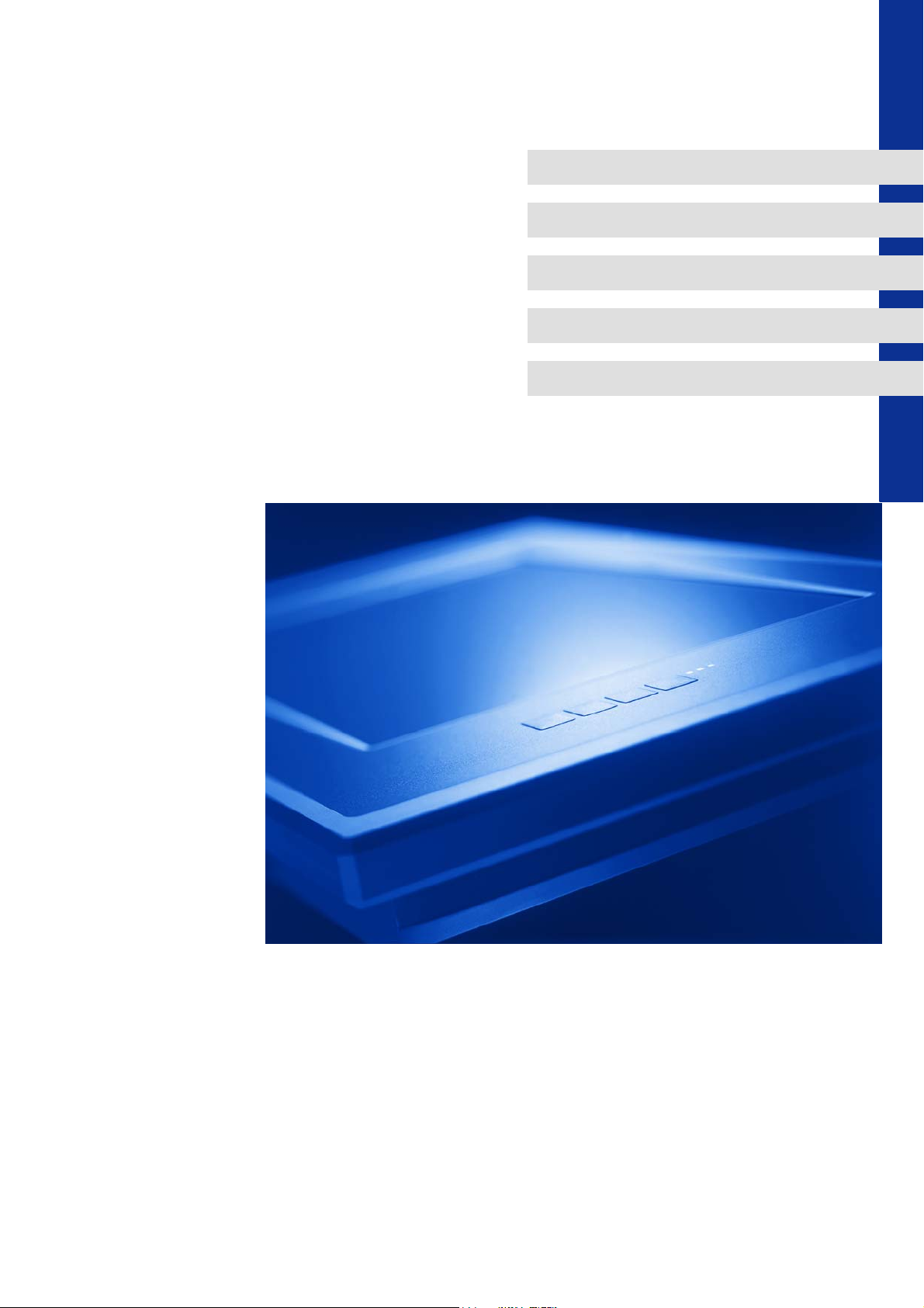
3 The "PC-based Automation" system
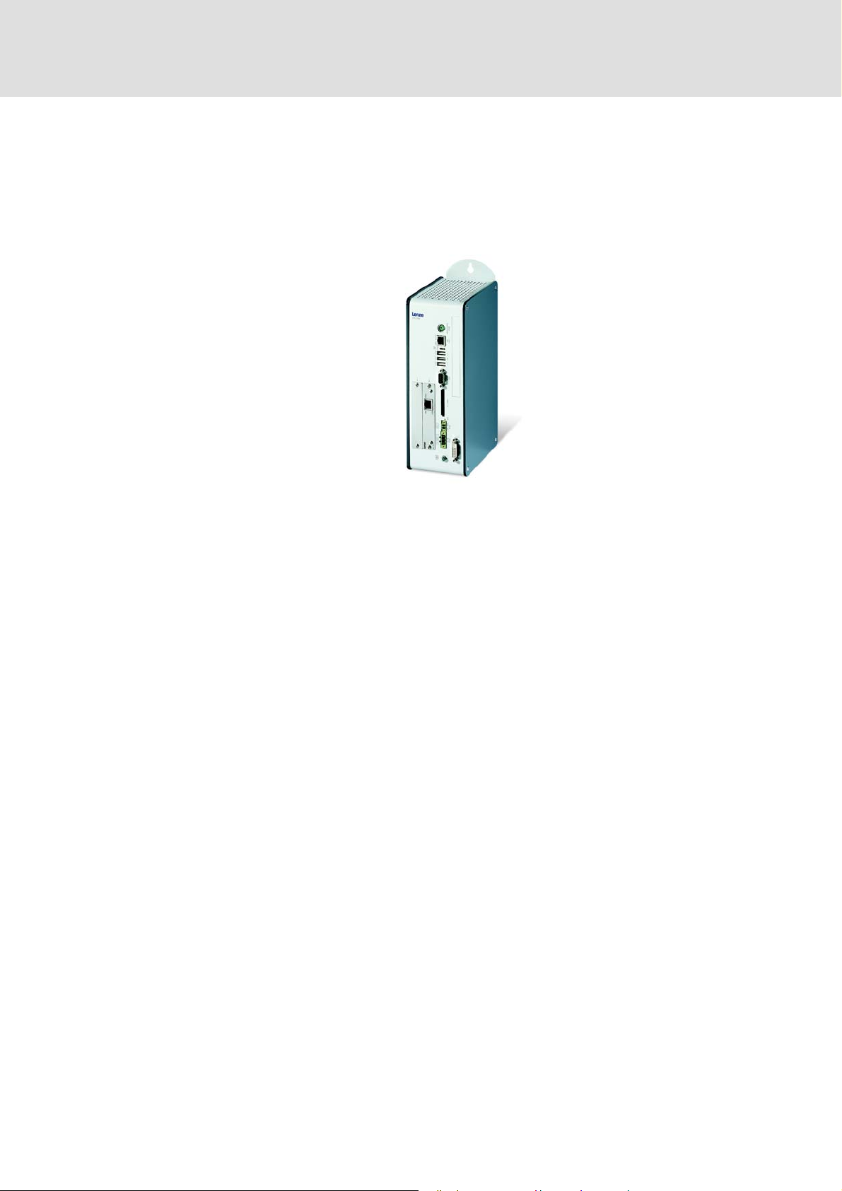
Industrial PCs (IPCs) become more and more important in the field of automation technology. Due to their scaling options and various combinations of visualisation and control on
one device, Industrial PCs provide clear advantages for many applications.
Lenze Industrial PCs are available with the following software equipment:
Industrial PC as component, on request with operating system, without further softwa-
re
Industrial PC as visualisation system
Industrial PC as control and visualisation system
The "PC-based Automation" system enables the central control of logic and motion systems.
For this purpose, Lenze provides coordinated system components:
Industrial PCs as control and visualisation system
– The IPC is the central component of the PC-based automation which controls the lo-
gic and motion functions by means of the runtime software.
– The IPC communicates with the field devices via the fieldbus.
– The IPCs are available in different designs.
Note!
Moreover, the "PC based automation" system comprises the HMI series
EL 1xx PLC. These devices differ considerably from the Industrial PCs with regard
to performance and various other details. However, the devices of the HMI series
EL 1xx PLC are able to perform smaller control functions.
12 L DMS 1.3 EN - 02/2011
Page 13

Control technology| System manual
The "PC-based Automation" system
Engineering tools for the Engineering PC
– The Engineering PC communicates with the IPC via Ethernet.
– The different Engineering tools serve to configure and parameterise the system.
Fieldbuses
Field devices
DMS 1.3 EN - 02/2011 L 13
Page 14

Control technology| System manual
System description
System components
4 System description
This chapter describes the basic structure of a control system based on an Industrial PC and
the required components.
4.1 System components
4.1.1 The Industrial PC
4.1.1.1 IPC types
Thanks to a consequently implemented platform strategy, Industrial PCs can be assembled
individually and are nearly optionally scalable with regard to power, display size, and function. This results in three different designs from which you can select the tailor-made platform for the prevailing automation solution.
This universal and scalable IPC platform is complemented by HMIs which are provided in
fixed configurations and can also fulfil automation functions in a restricted way.
The following designs are distinguished:
Embedded Line
HMI series EL 100 ( 16)
Command Station ( 17)
( 15)
Control cabinet PC ( 18)
14 L DMS 1.3 EN - 02/2011
Page 15
Control technology| System manual
System description
System components
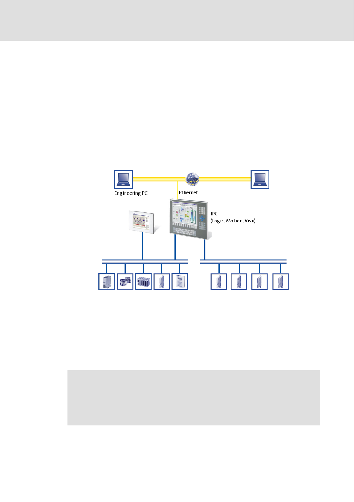
Embedded Line
Embedded Line Industrial PCs are designed for installation into control cabinets, casing of
machinery, or other mounting cutouts and are provided with bolts and clamping screws on
the rear face to ensure simplicity of assembly and assured sealing (IP65) even in aggressive
industrial environments.
Features of the supported device series EL 1800 ... EL 9800
Display
– Display size 8-19.0 inches
– Different front/keyboard variants
Interfaces:
– Ethernet on-board
– Option: 2 x CAN (example: one Logic bus line and one Motion bus line)
– Option: 4 x CAN (example: one Logic bus line and three Motion bus lines)
– Option: EtherCAT
– Option: PROFIBUS
DMS 1.3 EN - 02/2011 L 15
Page 16
Control technology| System manual
System description
System components
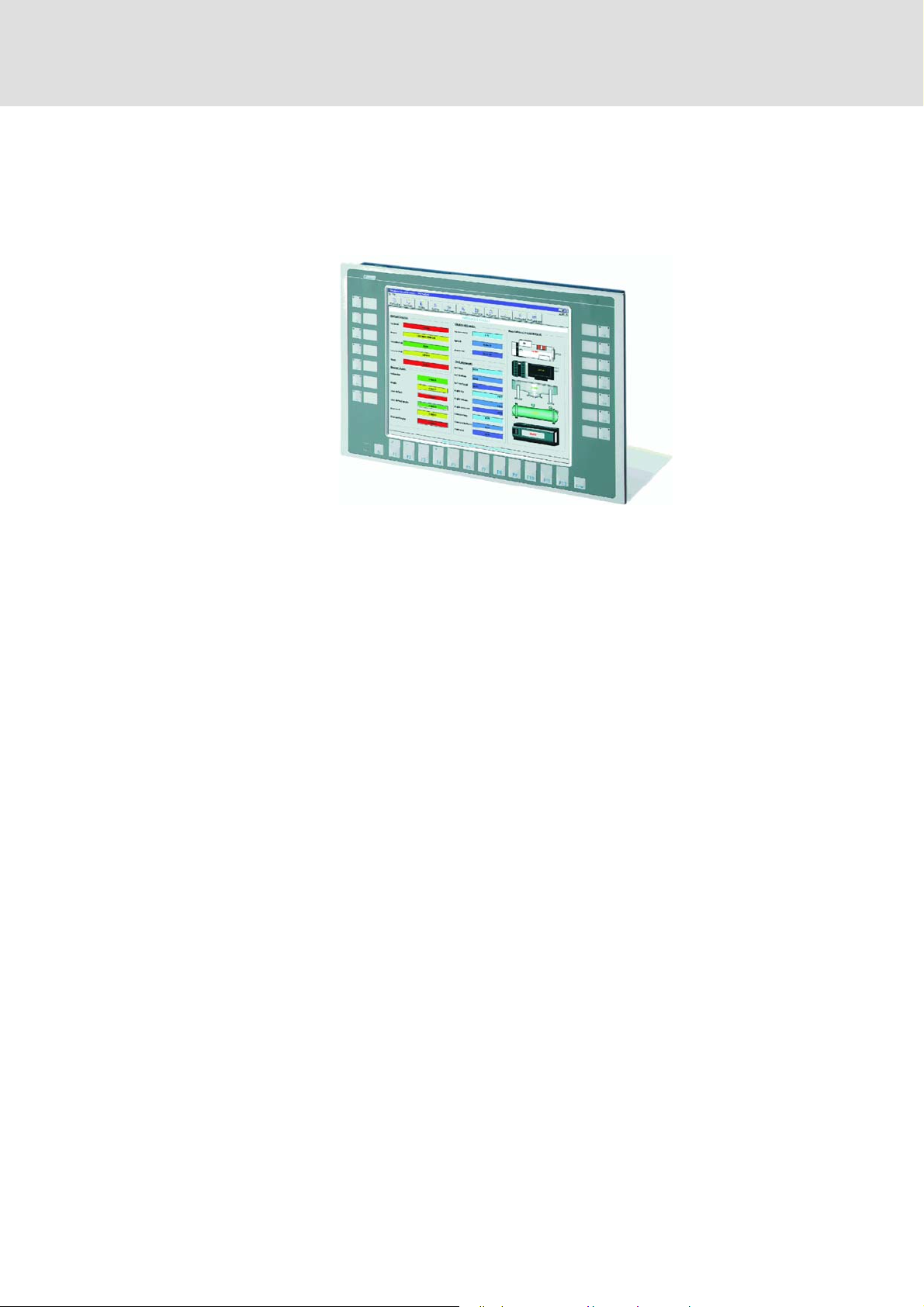
HMI series EL 100
– Display size 5.7-10.4 inches
– Integrated CAN interface
– Ethernet on-board
16 L DMS 1.3 EN - 02/2011
Page 17

Control technology| System manual
System description
System components
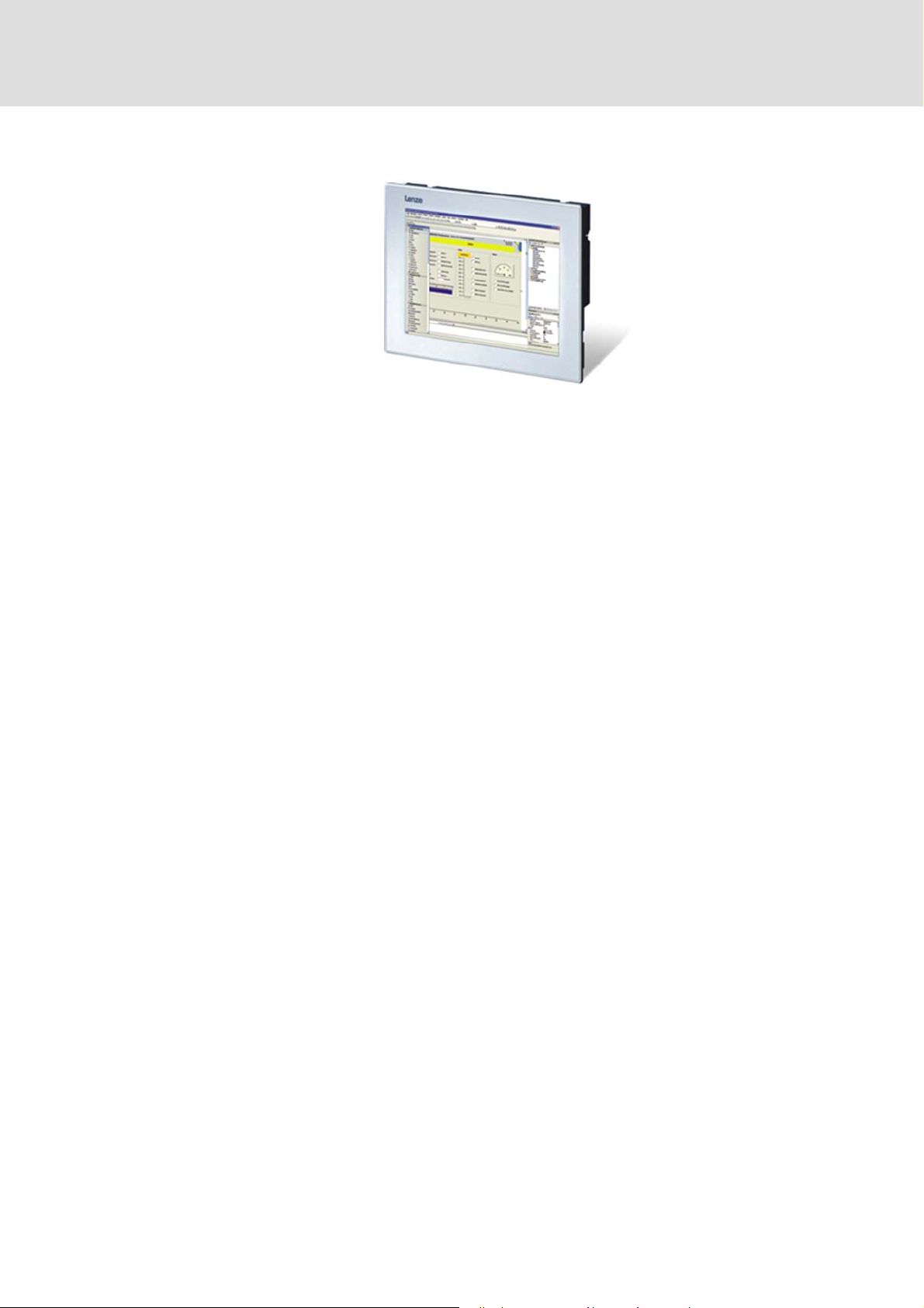
Command Station
Command Station (CS) is a stand-alone operator station (IP65) which is totally protected
against dust and water spray incursion. The flat enclosure is fitted with a mounting frame
at the rear edge which is intended for support arm mounting or direct fixing to the wall. To
allow the flexible implementation of individual operator concepts, the system offers numerous options and add-on operator consoles as for example:
– Touch screens,
– functional and alphanumeric keyboards,,
– Operator consoles with switching elements.
Features of the supported device series CS 5800 ... CS 9800
Display
– Display size 15.0-19.0 inches
– Different front/keyboard variants
Mounting
– Stand-alone, completely enclosed (IP65)
– Flexible support arm mounting
Interfaces:
– Ethernet on-board
– Option: 2 x CAN (example: one Logic bus line and one Motion bus line)
– Option: EtherCAT
– Option: PROFIBUS
DMS 1.3 EN - 02/2011 L 17
Page 18
Control technology| System manual
System description
System components
Control cabinet PC
Industrial PCs of the CPC series) are designed for the robust and continuous operation in
industrial applications. In contrast to the Embedded Line and Command Station types, the
CPC Industrial PCs are not provided with integrated displays. They are mounted into a control cabinet or a corresponding installation housing.
Features of the supported device series CPC 2800
Optional monitor panel as screen
– MP DVI (Embedded Line)
– CS DVI (Command Station)
Mounting
– Installation in control cabinet (IP20)
Interfaces:
– Ethernet on-board
– Option: 2 x CAN (example: one Logic bus line and one Motion bus line)
– Option: 4 x CAN (example: one Logic bus line and three Motion bus lines)
– Option: EtherCAT
– Option: PROFIBUS
18 L DMS 1.3 EN - 02/2011
Page 19

4.1.1.2 Runtime software
The Industrial PC is the core of the control system. To perform the task of the central control unit, the Industrial PC requires the runtime software.
The runtime software comprises the operating system. Moreover, further software components are required which, for example, execute the control program.
Control technology| System manual
System description
System components
The Industrial PCs are supplied completely with the runtime software. The different components of the runtime software are described in the following.
L-force Logic
The L-force Logic runtime software is a soft PLC. It serves to execute PLC programs which
have been created with the »PLC Designer« . These programs describe logic operations.
L-force Motion
The programs are processed cyclically by a multitasking operating system. L-force Logic
merely describes the function; the performance of the control system results from the interaction of the runtime software with the selected target system and thus directly depends on the selected processor and other factors.
L-force Logic is available for the following target platforms:
Industrial PCs:
– Embedded Line EL 1800-9800
– Command Station CS 5800-9800
– Control Cabinet CPC 2800
HMIs:
– EL100 PLC
( 20) serves to control drive-related processes.
DMS 1.3 EN - 02/2011 L 19
Page 20

Control technology| System manual
System description
System components
L-force Motion
In contrast to L-force Logic, L-force Motion serves to trigger controllers in addition to processing PLC programs.
In addition to all functions of the L-force Logic, also Soft Motion functions are supported
according to PLCopen part I and II.
L-force Motion is available for the following target platforms:
Industrial PCs:
– Embedded Line EL 1800-9800
– Command Station CS 5800-9800
– Control Cabinet CPC 2800
L-force Visu
The L-force Visu runtime software serves to extend your IPC to a visualisation device. The
visualisation can be installed on a separate IPC but can also run on the same IPC in parallel
to the control. There are different options for the communication interface connection.
The resulting four options and their advantages and disadvantages are described in the following.
L-force Visu is available for the following target platforms:
Industrial PCs:
– Embedded Line EL 1800-9800
– Command Station CS 5800-9800
– Control Cabinet CPC 2800
HMIs:
–EL 100
– EL 100 PLC
20 L DMS 1.3 EN - 02/2011
Page 21

Control technology| System manual
System description
System components
Integrated visualisation
Further information can be found in the documentation for »VisiWinNET®« Smart.
In this solution, the control and visualisation application are located on one PC. The PC in
Embedded Line and Command Station design has an integrated display so that no further
components are required.
Properties:
– Visualisation has access to variables of the control and parameters of the field de-
vices
– No impact on the real-time capability of the bus by the visualisation
– No further components required
DMS 1.3 EN - 02/2011 L 21
Page 22

Control technology| System manual
System description
System components
External monitor panel
This solutions corresponds to the integrated solution with regard to its performance. The
only difference is that the control and visualisation application are calculated on a PC without integrated display (control cabinet PC). It is displayed on an external monitor panel.
This solution offers advantages with regard to cabling, operating conditions, and accessibility.
Properties:
– Visualisation has access to variables of the control and parameters of the field de-
vices
– No impact on the real-time capability of the bus by the visualisation
– Use of any external monitor (for example: monitor panel in Command Station de-
sign) is possible.
22 L DMS 1.3 EN - 02/2011
Page 23

Control technology| System manual
System description
System components
Industrial PC as gateway
If it is required to separate control and visualisation, e.g. for performance reasons or due to
different operating systems, the control IPC can be used as gateway. The visualisation IPC
does not require any special fieldbus connection, only the Ethernet interface available as
standard is required. The implementation from Ethernet to the fieldbus is executed by the
Industrial PC.
Properties:
– Visualisation has access to variables of the control and parameters of the field de-
vices
– No impact on the real-time capability of the bus by the visualisation
– Several visualisations can access the same control
– Optimal for graphically complex visualisations
– Not available for HMI series EL100
DMS 1.3 EN - 02/2011 L 23
Page 24

Control technology| System manual
System description
System components
Independent control and visualisation
In this variant, the control and visualisation access the bus independently of each other.
This ensures the most possible independence of both systems but is only very rarely sensible in practice.
Note!
The configuration with control and visualisation that are independent of each
other is only recommended for systems without Lenze control!
Properties:
– Visualisation has access to parameters of the field devices
– Impact on the real-time capability of the bus by the visualisation is possible, thus it
is only suitable in Motion systems in a restricted way (also depending on the bus sys-
tem used)
– Depending on the prevailing bus system, several bus masters can be used which are
independent of each other:
–Use of CANopen
– In connection with EtherCAT a configuration with two bus masters is not possible.
– Available for HMI EL100
24 L DMS 1.3 EN - 02/2011
Page 25

4.1.2 Field devices
The following field devices can be used within the scope of the PC based automation. Depending on the bus system used, a device series may be applicable in a restricted way. For
details see Network topologies
4.1.2.1 Operation on the MotionBus
The MotionBus can drive controllers which support the standardised device profile DS402.
These are the following devices:
Controller
– Servo Drives 9400
– ECS servo system (motion device version with CiA 402 )
4.1.2.2 Operation on the fieldbus (Logic)
The fieldbus (Logic) can drive all field devices which have a suitable device description file.
The system is optimised for the following device series:
Control technology| System manual
System description
System components
( 32)
Controller
– 9400 Servo Drives Highline
– ECS servo system, device versions Speed and Torque, Posi and Shaft,
Application)
– 8400 Inverter Drives
Further field devices
– I/O system 1000
– I/O system IP20 compact/modular
– HMI series EL100
– HMI series EPM-Hx
DMS 1.3 EN - 02/2011 L 25
Page 26

Control technology| System manual
System description
System components
4.1.3 Engineering tools
4.1.3.1 Overview
Lenze provides various engineering tools to configure automation solutions according to
individual requirements.
Depending on the field device, the corresponding engineering tool must be used. The overview in table form shows the most important tasks of the engineering tools:
Field device Engineering tool Task of the engineering tool
9400 »Engineer« Parameter setting/configuring
8400 »Engineer« Parameter setting/configuring
ECS »GDC« Parameter setting/configuring
I/O system
1000
I/O system
IP20
Industrial PC »Engineer« Parameter setting/configuring
»Engineer« Parameter setting/configuring
»Engineer« Parameter setting/configuring
»GDC« Parameter setting/configuring
»WebConfig« Parameter setting/configuring
»IPC Backup & Restore« Restore after device exchange
»PLC Designer« Programming
»VisiWinNET®« Creating a visualisation
Online diagnostics with IPC as gateway
Online diagnostics with IPC as gateway
Online diagnostics with IPC as gateway
Online diagnostics with IPC as gateway
Online diagnostics with IPC as gateway
Online diagnostics with IPC as gateway
Online diagnostics
Online diagnostics
Bus configuration
26 L DMS 1.3 EN - 02/2011
Page 27

4.1.3.2 »PLC Designer«
You need the »PLC Designer« for
creating the control program for the IPC,
transferring the PLC projects to the IPC.
Basic functions of the »PLC Designer«:
Programming of Logic & Motion according to IEC 61131-3:
– Instruction list (IL),
– Ladder diagram (LD),
– Function plan (FP),
– Structured text (ST),
– Sequential function chart (SFC),
– Function block diagram (FBD).
Control technology| System manual
System description
System components
Certified function blocks according to PLCopen Part 1 + 2,
NC module library,
Graphic DIN 66025 Editor (G code) with DXF import,
cam editor.
4.1.3.3 Web-based parameterisation
The »WebConfig« is an engineering tool for web-based parameter setting of Industrial PCs.
Functions of the »WebConfig«:
Configuration and diagnostics of the Industrial PCs in the web browser by integrated
web server,
access to all IPC parameters,
access to an integrated IPC logbook.
DMS 1.3 EN - 02/2011 L 27
Page 28

Control technology| System manual
System description
System components
4.1.3.4 L-force »Engineer«
The L-force »Engineer« is used for parameter setting, configuration, and diagnostics of controllers, I/O systems, and Industrial PCs.
Functions in the »Engineer«:
– Hardware configurator,
– configuration editor,
– function block editor,
– graphical parameter setting interfaces.
The »Engineer« is used for:
Parameter setting and diagnostics of:
– 9400 Servo Drives,
– 8400 Inverter Drives,
– I/O system 1000,
– I/O system IP20.
4.1.3.5 »Global Drive Control« (»GDC«)
Access to the supported field devices via the IPC gateway function.
The »GDC« provides support for further field devices as the 8200 vector frequency inverter,
9300 servo inverter, and ECS servo system.
The basic function of the »GDC« is the parameterisation and diagnostics of controllers
which are not supported by the »Engineer«.
Access to the supported field devices via the IPC gateway function.
28 L DMS 1.3 EN - 02/2011
Page 29

4.1.4 Backup
Industrial PCs do not have hard disks as data memories. The operating system is saved on
memory chips. Depending on the series, this memory chip can either be permanently integrated or implemented using a memory card.
The following Industrial PC series use a
Compact Flash card (CF card) as storage medium:
EL 1800 - EL 9800,
CS 5800 - CS 9800,
CPC 2800.
The Compact Flash card is the "memory" of the IPC. Without this CF card, the IPC cannot
run.
»IPC Backup & Restore« serves to copy, duplicate, and archive these cards. To transfer userspecific data from the Industrial PC to an Engineering PC and vice versa, USB flash drives
can be used.
Control technology| System manual
System description
System components
The HMI series EL100 PLC uses an SD card for data exchange.
Further information can be found in the following documentation:
• Industrial PC - Parameter setting & configuration
• »IPC Backup & Restore«
• HMI EL 100
4.1.4.1 »IPC Backup & Restore«
»IPC Backup & Restore« saves the data bases of the Industrial PCs:
Compact Flash cards at the Engineering-PC:
–Duplicating,
– archiving,
– restoring.
USB flash drive:
– Prepare for backup and restore at the IPC,
– for creating backups
– use for restoring backups,
– use for updating the runtime software.
DMS 1.3 EN - 02/2011 L 29
Page 30

Control technology| System manual
System description
System components
4.1.4.2 UPS
IPCs can be equipped with a capacitor package. The capacitor package serves to buffer the
current supply of the IPC. This compensates current fluctuations and in case of a complete
power failure, these capacitors ensure the current supply. To bridge a longer power failure,
rechargeable battery packs are available.
Within this protected time, the control can save especially marked variable contents (retain variables). The retain variables will continue to be available in case of a restart of the system. Depending on the series, the capacitors are already integrated or can be connected
externally.
Further information can be found in the following documentation:
• Industrial PC - parameter setting & configuration
• HMI EL 100
30 L DMS 1.3 EN - 02/2011
Page 31

4.1.5 Visualisation with »VisiWinNET®«
To visualise the machine and systems engineering, »VisiWinNET®« is available as a modular and scalable visualisation system. Here, we distinguish between the engineering system and the runtime software.
The L-force Visu runtime software comes installed in the Industrial PC. In combination with
the control technology, it is the »VisiWinNET®« compact CE variant. It runs in parallel to the
other runtime software as for example L-force Logic on the Industrial PC.
4.1.5.1 Development system »VisiWinNET®«
The creation of the visualisation interface require the »VisiWinNET®« engineering system
which has to be installed on an Engineering PC. This is available in two versions:
Control technology| System manual
System description
System components
»VisiWinNET®« Smart
To create a simple interface, the »VisiWinNET®« Smart is available free of charge as a userfriendly visualisation system. It can be used as a flexible tool for creating simple applications or as service tool. »VisiWinNET®« Smart is provided with an own full-graphics integrated development environment and supports the user by ready-made templates. The
special strength of the system is the option to combine it with »VisiWinNET®« Professional.
• Features »VisiWinNET®« Smart
– For simple B&B applications
– For applications in the machine-oriented field
»VisiWinNET®« Professional
The »VisiWinNET®« Professional system is completely implemented in the
Microsoft® Visual Studio .NET integrated development environment and is the basis for
creating visualisation and SCADA applications with high functionality. Ready-made templates and modules serve to create applications fluently per "drag and drop".
If required, the system permits individual program-related changes on the basis of Visual
Basic .NET and C#. This serves to solve company-specific and complex tasks when the standard visualisation functions are not sufficient.
• Features »VisiWinNET®« Professional
– For complex B&B applications
– For client/server-based SCADA systems
– For individual and company-related programming
– For connection to databases or other Office programs
– For use of complex report functions
DMS 1.3 EN - 02/2011 L 31
Page 32

Control technology| System manual
System description
Network topologies
4.2 Network topologies
The Lenze control technology provides master interface connections for the following communication systems:
CANopen: Tried-and-tested system for smaller plants
EtherCAT: Ethernet-based system for every application
PROFIBUS: For the greatest selection of different field devices
Lenze's control technology is based on CANopen profiles. The communication system supported by the respective application is used for data transfer.
Tip!
The Lenze support assists you in selecting the fieldbus system tailored for your application and the suitable Industrial PC components.
Depending on the bus system used, the basic structure of the network varies. The bus system also influences the usability of the different device families. This is described in the following:
32 L DMS 1.3 EN - 02/2011
Page 33

4.2.1 Control technology with CANopen
CANopen as the basis for the Lenze control technology
The control technology based on CANopen serves to implement the classical Lenze de-
vice series that have the system bus (CAN) on board. Thus, solutions at optimal cost are
possible.
In order to extend the existing limits of the CAN bus, up to four CAN lines can be used
which are synchronised among each other.
The highest possible number of nodes on a CAN line depends on the baud rate and the
set cycle time.
– Example: Three nodes can be connected to the CAN bus with a setpoint PDO and an
actual value PDO each at a cycle time of 1 [ms] and a baud rate of 1[MBit/s].
Control technology| System manual
System description
Network topologies
Physical structure
Due to the real time requirements of the bus system and the limited transmission capacity,
it is vital with CANopen to separate the bus line with Motion from the one with components that are controlled via PLC functionalities only (Logic). Moreover it is required, depending on the number of Motion nodes and the bus cycle time, to create several Motion bus
lines.
CANopen uses separate CAN interfaces to operate Logic and Motion nodes:
The IPCs support up to four CAN interfaces.
– Interface 1 is CANOpen(Logic),
– Interface 2-4 is CANOpen(Motion).
– If no Logic is required, the interface 1 can additionally be Motion. Thus, up to four
synchronised Motion buses are possible.
Note!
• When the IPC type "Command Station" is used, only two bus lines are possible!
• Depending on the required number of Motion nodes and bus cycle time, up
to four Motion bus lines can be created.
• When the IPC series "Command Station" CS x8xx is used, only two bus lines
are possible.
Convention for "PC based Automation"
• Bus line 1 (CAN1): CANopen (Logic) or CANopen (Motion)
• Bus line 2 - 4 (CAN2 - 4): CANopen (Motion)
DMS 1.3 EN - 02/2011 L 33
Page 34

Control technology| System manual
System description
Network topologies
4.2.1.1 CANopen Logic
The Logic bus line is used to operate controllers which
execute simple movements.
do not have a Motion functionality,
are controlled via PLC functionalities only.
4.2.1.2 CANopen (Motion)
The Motion bus line is used to control controllers which, for instance, execute complex movements in several dimensions.
The "L-force Motion" runtime software contains the PLCopen libraries and supports the
soft motion control for driving the "9400 StateLine" series and the "ECS servo system".
Further information and performance features about CANopen can be found in the
following documentation:
• CANopen communication manual
34 L DMS 1.3 EN - 02/2011
Page 35

4.2.2 EtherCAT
Note!
EtherCAT is a very powerful bus system which is based on Ethernet.
EtherCAT is suitable for greater applications
The highest possible number of nodes at an EtherCAT line mainly depends on the per-
formance of the Industrial PC due to the great bandwidth of this bus system.
– Depending on the Industrial PC used and the required computing time of the appli-
cations which run on the IPC (PLC and optional visualisation), a high number of nodes
at a low cycle time is possible.
Control technology| System manual
System description
Network topologies
EtherCAT is not available for Industrial PCs of the device series EL 1xx, EL x8xx,
CS x8xx and CPC x8xx in combination with the Control technology release 2.5.
Physical structure
Thanks to the integrated synchronisation mechanisms via "distributed clocks", EtherCAT
offers excellent real-time features. Thus, Motion and PLC applications can be operated via
the same bus and the number of the nodes to be controlled and the maximum bus length
is much higher compared to a CANopen system.
EtherCAT can control all field devices at one common interface. Thus, no division into
Logic fieldbus and Motionbus is required.
The Industrial PC provides the interface for connecting EtherCAT.
DMS 1.3 EN - 02/2011 L 35
Page 36

Control technology| System manual
System description
Network topologies
Further information and performance features about EtherCAT can be found in the
following documentation:
• EtherCAT communication manual
36 L DMS 1.3 EN - 02/2011
Page 37
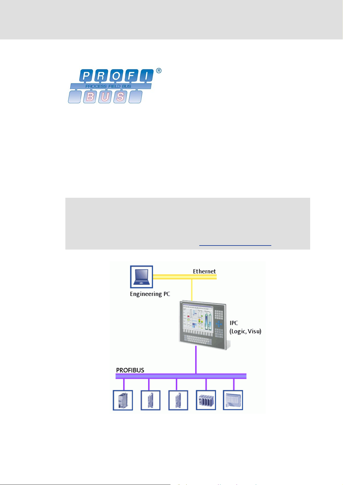
4.2.3 PROFIBUS master
Today, PROFIBUS is the most commonly used fieldbus system. Because it comes with the
widest range of various field devices, the PROFIBUS is occasionally prioritised over more
modern bus systems. Due to the low bandwidth and synchronisation mechanisms, the
PROFIBUS is only provided as logic bus within the "PC-based Automation".
We recommend to use the PROFIBUS for the following applications:
Control of system parts that have already been automated with PROFIBUS and another
control system.
Use of field devices that are not available for e.g. EtherCAT or CANopen.
Control technology| System manual
System description
Network topologies
Combination of PROFIBUS as logic bus with a second bus system as motion bus.
Further information and performance features about EtherCAT can be found in the
following documentation:
• PROFIBUS communication manual
General information about the PROFIBUS can be found on the Internet website
of the PROFIBUSNutzerorganisation e.V.: http://www.profibus.com
.
DMS 1.3 EN - 02/2011 L 37
Page 38

Control technology| System manual
System description
Network topologies
Physical structure
The Industrial PC (IPC) is the PROFIBUS master. It can communicate with one or several
stations (slaves).
The PROFIBUS has an internal line topology (without repeater) or a tree topology (with
repeater).
The PROFIBUS network must be terminated at the first and last station.
The bus terminating resistor is integrated in the bus connector and activated by a
switch.
4.2.4 Mixed operation
Note!
Mixed operation is only possible with Industrial PCs provided with two extension slots for communication cards.
• Thus, the "Command Station" is not suitable for mixed operation!
4.2.4.1 Combination of CANopen and EtherCAT
It is possible to combine both bus systems CANopen and EtherCAT in a control system.
This combination of CANopen and EtherCAT may be sensible if controllers with EtherCAT
are available but further peripheral devices have to be controlled which are only available
with CANopen. Both bus systems are synchronised via the control system, the IPC (controller).
38 L DMS 1.3 EN - 02/2011
Page 39

For the configuration and parameterisation of the bus systems the data in the
corresponding communication manuals apply:
• CANopen communication manual
• EtherCAT communication manual
• PROFIBUS communication manual
4.2.4.2 PROFIBUS with CANopen or EtherCAT
Note!
A mixed operation is only possible with Industrial PCs which have two extension
slots for communication cards.
• When the Command Station is used, a mixed operation is not possible!
Control technology| System manual
System description
Network topologies
The PROFIBUS bus system can be combined with CANopen or EtherCAT.
This makes sense if not all field devices are available for the same bus system or a mo-
tion bus is required in parallel to the PROFIBUS.
The bus systems are synchronised in the control, the IPC (controller).
The following combinations are allowed:
PROFIBUS (as logic bus) and up to two CAN interfaces (as motion bus)
DMS 1.3 EN - 02/2011 L 39
Page 40

Control technology| System manual
System description
Network topologies
PROFIBUS (as logic bus) and EtherCAT (as motion bus)
"Control technology CANopen" communication manual
• Here you can find detailed information on how to commission CANopen components.
"Control technology EtherCAT" communication manual
• Here you can find detailed information on how to commission EtherCAT components.
40 L DMS 1.3 EN - 02/2011
Page 41

5 Commissioning of the system
5.1 General commissioning steps
This chapter informs you about the basic steps to commission a control system. The overview in table form shows the order of commissioning steps.
Detailed information about the single commissioning steps...
• ... with CANopen can be found in the "CANopen control technology" communication manual.
• ... with EtherCAT can be found in the "EtherCAT control technology"
communication manual.
Commissioning step Description Engineering tools
Commissioning of the Industrial PC. • Establishing the general readiness
Planning/installation of the network
(as for example electrical wiring, setting of DIP switches)
Project planning and commissioning
of the field devices
Project planning of the control • Creating:
Creating a visualisation • If the IPC is provided with a moni-
for operation of the IPC.
• The general readiness for operation enables the usability of the
gateway in the IPC so that the
communication with field devices
is possible via the integrated gateway.
Industrial PC as gateway
• This serves to prepare the field devices for communication with the
IPC and the engineering tool
which communicates via the
gateway of the IPC.
• Using the gateway in the IPC, the
"Engineer" and "GDC" programs
can communicate with the corresponding field devices and carry
out the required parameter setting steps.
–the control configuration,
– bus configuration,
–control program
tor, a visualisation can take place
there in parallel to the control.
• To create the visualisation and to
download it to the IPC, use the
program
»VisiWinNET®«
Integrated visualisation
Control technology| System manual
Commissioning of the system
General commissioning steps
Optional »Engineer« or
»WebConfig«
( 23)
None
»Engineer«
»GDC«
»PLC Designer«
»EtherCAT Configurator«
»VisiWinNET®«
( 21)
DMS 1.3 EN - 02/2011 L 41
Page 42

Control technology| System manual
Commissioning of the system
General commissioning steps
Commissioning step Description Engineering tools
Safe data • By means of the
Backup
• Further information can be found
Diagnostics • The control system can be diag-
• If further diagnostics is required
»IPC Backup&Restore« program, a
copy of the Compact Flash card
can be made and saved on any Engineering PC for backup.
( 29)
in the following documentation:
– Industrial PC parameter setting
& configuration,
–Software Manual
»IPC Backup&Restore«
nosed by means of the "Engineer"
or "Webconfig"
– This, for instance, enables you to
have a look into the logbook of
the Industrial PC.
up to the level of the field device,
also use the "Engineer" or "GDC",
depending on the field device type, using the gateway function of
the IPC.
»IPC Backup&Restore«
»WebConfig«
»Engineer«
»GDC«
Further information about the use of the single engineering tools can be found in
the corresponding software documentation.
42 L DMS 1.3 EN - 02/2011
Page 43

6 System architecture
To commission the control system, an Engineering PC is required. This can be a standard
laptop. Here, the programs are installed which are required for configuration, parameter
setting, and commissioning of the control system. The programs are listed in chapter 3.2.3.
The Engineering PC which is connected with the Industrial PC via Ethernet, serves to install
the control system. For the operation of the control and visualisation system, the Engineering PC is not required anymore.
An Engineering PC can be used for the configuration of any number of Industrial PCs.
Control technology| System manual
System architecture
DMS 1.3 EN - 02/2011 L 43
Page 44

Control technology| System manual
System architecture
IPC as gateway
6.1 IPC as gateway
The Engineering PC is not only required for commissioning the Industrial PC but also for
commissioning the subordinated field devices. To establish an online connection between
an Engineering PC and a field device, e.g. a controller, two ways are possible:
Direct coupling
IPC as gateway ( 45)
6.1.1 Direct coupling
In case of direct coupling, the Engineering PC has a special interface module for the corresponding fieldbus, e.g. a USB system bus adapter for coupling to the CANopen bus system.
Advantage:
The connection of the Engineering PC to the drive is totally independent from the control.
Thus, it is irrelevant whether the control is already available in the system, or already commissioned, etc.
The speed at data transmission is optimal with direct coupling. The IPCs are used as gateway, this optimal speed cannot be achieved.
( 44)
Disadvantage:
A special interface connection is required for the Engineering PC
The communication of the Engineering PC with the field device may interfere with the bus.
It is, for instance, possible that the real-time capability of the control is disturbed by the Engineering PC since the Engineering PC overloads the bus or transmits telegrams at times
the control needs for transmission of synchronisation protocols.
44 L DMS 1.3 EN - 02/2011
Page 45

6.1.2 IPC as gateway
In the second case, the Engineering PC is not provided with a special fieldbus coupling. Only
the Ethernet interface available as standard is required. The implementation from Ethernet to the fieldbus is made via the Industrial PC.
Control technology| System manual
System architecture
IPC as gateway
Note!
• The "IPC as gateway" function is not available in combination with PROFIBUS.
• Thus, "Going online" with the »Engineer« or the »GDC« via the IPC as gateway
is not possible.
Advantage:
The Engineering PC does not require a special interface connection
The Engineering PC is the only master for the bus and can thus guarantee the real-time capability of the bus since it controls the access to the bus itself. Thus, it is ensured that the
bus is always free for the control if required.
Disadvantage:
The gateway can only be used if the basic configuration of the IPC and the bus has been
carried out.
The communication speed for a download to a field device using the Engineering PC is slower than with direct coupling. The extent of delay depends on whether the control is active
itself at this moment or only the gateway of the IPC is used.
Conclusion
Direct coupling is an appropriate means to commission field devices for the first time
(download). The download times are optimal and it is not required that the control has to
run.
DMS 1.3 EN - 02/2011 L 45
Page 46

Control technology| System manual
System architecture
Function blocks
As soon as the control has been commissioned, no direct coupling should be used anymore
since, depending on the bus system, the real-time capacity of the bus may be disturbed.
6.2 Function blocks
A number of available function blocks offers the opportunity to access parameters of the
Industrial PC from the PLC program. These are the following:
Device parameters of the Industrial PC,
Device parameters of the field devices,
Logbook entries of the Industrial PC.
Further information about the function blocks can be found in the following
documentation:
• Industrial PC - Parameter setting & configuration
46 L DMS 1.3 EN - 02/2011
Page 47

Control technology| System manual
7 Remote maintenance and diagnostics
In the PC technology, there are various standard mechanisms for remote connections between the nodes.
The standard mechanisms
– are based on the Ethernet bus system or the protocols used for Ethernet.
– can be used between Engineering/remote maintenance PC and IPC.
It is irrelevant whether a local connection or a remote connection exists between Engineering/remote maintenance PC and IPC.
All access mechanisms described in the following can be used
– with direct coupling between the PCs within a local network,
– with a remote connection.
To establish a remote connection, a router is required. A router can be a separate device or
the IPC itself. A router establishes a remote connection between two network segments.
Remote maintenance and diagnostics
Typically, routers are used for the following connection types:
Analog phone (modem),
ISDN,
DSL.
The client/server connection between the Engineering PC and Industrial PC is characteristical for a remote maintenance.
A server runs on the device to be accessed from afar. The server waits for a client to give a
signal from afar and want to access the PC. Depending on the action you want to carry out
from afar, different server types are available.
When a remote connection has been established once, you can work with the same programs that are used for the local connection via Ethernet, as for example L-force »Engineer« or web server. Moreover, programs exist which are especially suitable for accessing
parts of the IPC. You can even redirect the complete screen content of the IPC so that you
can remote control it. The different programs available are described briefly in the following.
DMS 1.3 EN - 02/2011 L 47
Page 48

Control technology| System manual
Remote maintenance and diagnostics
Dial-in on the IPC
Note!
Setting a remote maintenance is a potential safety risk! This is particularly relevant if the computer to be remote-controlled is connected to an Ethernet network. Always contact your IT administrator to take the necessary safety
measures.
7.1 Dial-in on the IPC
An RAS server runs on the IPC. A user can log-in via modem/ISDN card on this RAS server. If
someone dials-in from a remote maintenance PC via this medium, the IPC executes a password check and then activates the connection.
Further information about the function and configuration of RAS servers can be
found in the following documentations:
• Industrial PC - parameter setting & configuration
• HMI EL 100 with Windows® CE
7.2 Computer access via Telnet
Note!
Telnet is a standard mechanism reserved for experienced users to change system settings.
The Telnet protocol serves to access the data of a PC. Telnet requires an existing local connection or remote connection. Telnet is a command line-oriented protocol.
7.3 File transfer via FTP
To transfer files from one PC to another, FTP is frequently used. FTP is the abbreviation for
File Transfer Protocol.
FTP requires an existing local connection or remote connection.
FTP can be used via the command line, similar to Telnet.
Many programs have an integrated FTP support as for example the Internet Explorer.
Further information about the function and configuration of FTP can be found in
the following documentations:
• Industrial PC - parameter setting & configuration
• HMI EL 100 with Windows® CE
48 L DMS 1.3 EN - 02/2011
Page 49

7.4 Web server
If the PC has a web server, the user is provided with ready-made views which can be displayed via a browser as the Internet Explorer. Depending on the structure of these web pages, they may allow the change of parameters. Calling a web server requires an existing
local connection or remote connection.
All Lenze IPCs which support the control technology have an integrated web server. The
web server allows for a web-based parameter setting.
Further information about the function and configuration of FTP can be found in
the following documentations:
• Industrial PC - parameter setting & configuration
• HMI EL 100 with Windows® CE
Control technology| System manual
Remote maintenance and diagnostics
Web server
DMS 1.3 EN - 02/2011 L 49
Page 50

Control technology| System manual
Remote maintenance and diagnostics
Redirecting screen contents/entries
7.5 Redirecting screen contents/entries
Comfortable programs for remote maintenance allow for a complete redirection of the entire screen contents. Moreover, all keyboard entries or mouse movements are transmitted
from the local PC to the remote PC. Thus you can operate the remote PC as if you would be
directly in front of it. However, the quality of the remote connection is decisive as the speed
of the presentation of the screen contents depends strongly on it. A bad connection may
render the operation of a program using the mouse impossible since you cannot track the
movements of the mouse pointer. In such cases, you can use the command line-based protocols as FTP and Telnet, depending on the function to be executed.
The use of a screen redirection requires an existing local connection or remote connection.
For redirecting the screen contents, the following programs are available, depending on
the device type:
EL100:
– VNC (see manual EL100)
EL 1800-9800, CS 5800-9800, CPC 2800:
– Cerdisp/Cerhost
7.5.1 Virtual Network Computing (VNC)
Virtual Network Computing (VNC) is a software developed by Olivetti & Oracle Research
Laboratory (from 1999 AT&T), which shows the screen content of a remote computer (with
the VNC server software running) on a local computer (with the VNC viewer software run-
7.5.2 Cerdisp/Cerhost
ning) and transmits the keyboard and mouse movements from the local computer to the
remote computer. Alternatively, an "only read" mode is possible, where local entries have
no impact on the remote computer.
VNC has an open source licence which means that the source code is free of charge for interested developers so that further developments are allowed. Thus, various VNC versions
are available in the internet.
The VNC server is already installed in the devices of the HMI series EL100 by default. The
Engineering PC requires the VNC viewer software. It can be downloaded from the download area of the Lenze homepage AKB and is enclosed to the CD which is supplied with the
devices.
Microsoft provides the software combination Cerdisp/Cerhost for redirecting screen contents and keyboard and mouse entries.
The Cerdisp is installed on the Industrial PC. The IPCs of the
EL 1800 series are supplied completely installed.
50 L DMS 1.3 EN - 02/2011
Page 51

8 Appendix
This chapter informs you about the basics of the OPC communication standard and gives
you an overview of where OPC is used in the Lenze control technology.
8.1 Basics of the OPC standard
The industrial operation in the automation technology can be divided into three levels:
Control technology| System manual
Appendix
Basics of the OPC standard
1. The master level manages and visualises information.
2. The control level manages information and serves as process control.
3. The field level manages data and provides measured values.
The control and master level mostly use PC components. The field level consists of hardware in the form of sensors and actors.
PC-based automation solutions are used to implement a suitable process connection to enable the access to the data of the field level. To exchange data with PC applications, a special driver is required with a conventional automation solution. Each hardware requires its
own driver. Thus, the corresponding software application should be adapted to each hardware. The OPC standard simplifies the communication between Engineering PC and Industrial PC and the access to the data of the field level.
8.1.1 Communication by means of OPC
OPC is a standardised software interface for manufacturer-independent communication
in the automation technology. OPC stands for Openness, Productivity, Collaboration, formerly OLE for Process Control. The target is to exchange data between different software
applications.
DMS 1.3 EN - 02/2011 L 51
Page 52

Control technology| System manual
Appendix
Basics of the OPC standard
8.1.2 OPC as universal driver
The OPC-Data Access specification provides a universal driver for the automation technology. The universal driver encapsulates the original driver and provides the generally understandable services via a universal interface. The application of the automation
technology comes across a uniform interface when accessing the data on the field level.
8.1.3 OPC items
The process variables are represented by items when an OPC server is used. Thus, an item
is the transport medium of a variable. Since in the most cases, only a part of the items provided by the OPC server is of interest for the client, they can be summarised in groups. "different
In addition to the contents of the variables, an item contains various additional information for the data. This additional information is called metadata.
An item is assigned to the following metadata:
Item definition: Unambiguous string of digits to identify an item
Access rights: Access authorisation to the item (reading, writing, or both)
Canonical data type: original data type as in the field device
Time stamp: Time of the last change of an item
OPC quality: State of an item, references to communication errors
An OPC client either receives the values of the items from the PLC or from the item cache
of the OPC server.
52 L DMS 1.3 EN - 02/2011
Page 53

8.1.4 OPC tunnel
If an OPC server and an OPC client are located on different computers, OPC tunnels are
used. This is a software which is installed on both computers and acts as client and server
itself. The data is transferred between the OPC server and OPC client by the OPC tunnel via
the TCP/IP protocol. Thus, OPC tunnels provide a platform and network-spanning communication of OPC-based applications. This serves to avoid the "conventional" communication of distributed client/server applications via DCOM.
Control technology| System manual
Appendix
Basics of the OPC standard
OPC tunnels are mainly used to connect the Engineering PC with the Industrial PC. However they can also be used in connections between the Industrial PC and other computers.
DMS 1.3 EN - 02/2011 L 53
Page 54

Control technology| System manual
Glossary
9Glossary
A
AIF Abbreviation for "Automation Interface". Lenze-specific interface at the con-
Application Implementation of a precise function (e.g. speed control) on an individual de-
Application variable Structure of element variables which is communicated via network(s) using a
Axis An axis is a special variant of a system module and basically contains at least
B
Bus server Fieldbus-specific OPC server according to DRIVECOM specification.
troller on which a communication module can be plugged.
Communication module
vice.
specific transfer mode. The definition of an application variable is completely
independent of a specific type of network.
Element variable
one controller and one motor, but depending on the application it may contain further devices, such as gearboxes and encoders.
OPC
DRIVECOM
C
CAL Abbreviation for "CAN Application Layer". Communication standard (CiA DS
CAN Abbreviation for "Controller Area Network". Serial, message-oriented (not
CANopen Communication profile (CiADS301, version 4.01), which has been created un-
Catalogue A catalogue contains descriptive information on all element types that form
Catalogue package A catalogue package consists of several related catalogues and is named and
CiA Abbreviation for "CAN in Automation (e. V.)": International manufacturer and
Code Parameters for Lenze devices for setting the device functions.
COM Abbreviation for "Component Object Model": Architecture developed by Mi-
Communication module Generic term for Lenze function modules and communication modules.
201-207) which provides the objects, protocols and services for the event or
polling-controlled transfer of CAN messages and the transfer of greater data
areas between CAN nodes. Furthermore, CAL offers powerful processes for an
automatic assignment of message identifiers, the initialisation of network
nodes and the assignment of an individual identification to network nodes.
node-oriented) bus system for max. 63 nodes.
der the umbrella association of the CiA ("CAN in Automation") in conformance
with the CAL ("CAN Application Layer").
an »Engineer« project. The »Engineer« uses various catalogue types, e.g. for
devices, device modules, technology applications, function blocks, and motors. Each catalogue is labelled by versioning.
versioned. Multiple versions of a catalogue package can be added to an »Engineer« installation. Every »Engineer« project can use an optional number of
catalogue packages. Each catalogue package can be used in exactly one version.
user organisation with the target to worldwide distribute the knowledge of
the internationally standardised CAN bus system (ISO 11898) and promote its
technical further development.
Internet: http://www.can-cia.org/
crosoft® for the co-operation of individual executable software components
(objects) which communicate with each other in a similar manner and are not
connected until the program is running.
Function module
Communication module
54 L DMS 1.3 EN - 02/2011
Page 55

Control technology| System manual
Glossary
Communication module Device extension which can neither fulfil a function nor is able to communi-
cate without a device.
Controller Generic term for Lenze frequency inverters, servo inverters, and PLCs.
D
DCOM Abbreviation for "Distributed Component Object Model": COM where the ex-
ecutable objects are distributed to different computers within one local area
network.
COM
DRIVECOM "DRIVECOM User Group e.V.": International organisation of manufacturers of
drive technology, universities and institutes with the target to develop an easy
integration of drives into open automation structures.
Internet: http://www.drivecom.org/
Drive Mechatronic unit which serves a certain purpose and can be provided with
mechanical, electrical and logical interfaces with regard to its environment. A
device is called a "communication-capable device" if it is able to communicate
as a node in a network.
Unlike the mechatronic unit "system module", a device already is created by
the manufacturer and not only when a system of a concrete project is created.
Examples of devices: drive controllers, PLCs, motors, gearboxes, sensors, encoders
DriveServer Lenze software which provides an easy integration of drives into open auto-
mation structures based on OPC ("OLE for Process Control").
OPC
E
Element variable Variable which is used in an application to implement a specific function of
the respective device.
Application
F
FIF Abbreviation for "Function Interface". Lenze-specific interface at the controller
Function module Device extension for the FIF interface which can neither fulfil a function nor is
which can be plugged onto a function module.
Function module
able to communicate without a device.
FIF
H
Hyperlink Optically highlighted reference which is activated by means of a mouse-click.
I
IPC Abbreviation for "Industrial PC". The IPC is a central system for controlling
and/or visualising machines.
DMS 1.3 EN - 02/2011 L 55
Page 56

Control technology| System manual
Glossary
M
Machine application Implementation of a function which is generated by the interaction of several
Menu bar Bar in the upper position of the application window below the title bar which
N
NMT Abbreviation for "Network Management": Services and protocols for initialisa-
O
OLE Abbreviation for "Object Linking and Embedding": Insertion of functional ob-
OPC Abbreviation for "OLE for Process Control": Defines an interface based on the
communication-capable devices. A machine application is defined by the (device) applications involved and the exchange of application variables between
them.
shows the names of menus that open with a mouse-click.
tion, configuration, management and network monitoring within one CAN
network according to the master/slave principle.
CAN
jects into other applications, e.g. a Microsoft® Excel table into a Microsoft®
Word document.
Microsoft® Windows® technologies OLE, COM and DCOM which is enabled via
a data exchange between different automation devices and PC programs
without considering driver and interface problems.
COM
DCOM
P
PDF Abbr. for "Portable Document Format", a universal file format developed by
Adobe for the exchange of electronic documents. With this free software Adobe® Reader® PDF files can be displayed and printed, independent of the application and platform used for the creation.
Internet: http://www.adobe.com/
PLC Abbreviation for "Programmable Logic Controller".
PLC Designer Integrated development environment for the creation of IEC 61131 programs
for Lenze PLCs.
Port Connection point or interface of an application or machine application. Input
ports serve to transferit e.g. setpoints and control commands to an application, output ports serve to, for instance, provide actual values and status messages.
Application
Machine application
Project element The topmost element (root element) in the project view with the global prop-
erties of the project.
R
Reset node Function for Lenze devices with a system bus (CAN) interface, by which the de-
vice can be reinitialised if a change with regard to the data transfer rate, node
address, or identifiers is effected. Ein Reset-Node kann bei Lenze-Geräten durch erneutes Netzschalten, einem Reset-Node-Befehl perNMT-Kommando
oder über die entsprechende Codestelle erfolgen.
CAN
NMT
56 L DMS 1.3 EN - 02/2011
Page 57

Control technology| System manual
Glossary
S
ST Abbreviation for "Structured Text": Standardised programming language
System bus (CAN) Lenze bus system based on the communication profile CANopen (CiADS301,
System module Generic term for a mechatronic unit which can generally include several devic-
T
Title bar Bar in the upper position of the application window which contains the pro-
Top-down method Design and implementation method which provides a step-by-step transition
(IEC 61131-3) for programmable logic controllers (PLC).
version 4.01).
CAN
es, one or several networks, information on parameter values, program logic
and documentation.
A system module provides a specific technological function. It interacts with
its environment and can be generally reused in another environment or system. The interfaces of a system module are provided by the interfaces of its
components.
gram symbol in the left-most position and the window symbols in the rightmost position.
Window symbol
from the general comprehensive structure to more and more special details
until the entire project structure has been created.
V
Variable Name of a data memory which can adopt values defined by the data type and
information on the variable declaration.
W
Window symbol Button in the right-most position of the title bar to change the window pres-
entation or close the window.
X
XML
Abbreviation for "EXtensible Markup Language", a meta language which describes the structure of documents.
DMS 1.3 EN - 02/2011 L 57
Page 58

Control technology| System manual
Index
10 Index
A
Application notes 10
C
Combination with CANopen and EtherCAT 39
Conventions used 7
Copyright information 7
D
Document history 7
E
E-mail to Lenze 59
F
Feedback to Lenze 59
L
Layout of the safety instructions 10
M
Mixed operation 39
S
Safety 11
Safety instructions 10
Structure of safety instructions 10
T
Target group 6
Terms 9
58 L DMS 1.3 EN - 02/2011
Page 59

Your opinion is important to us
)(('%$&.
These instructions were created to the best of our knowledge
and belief to give you the best possible support for handling
our product.
If you have suggestions for improvement, please e-mail us to:
feedback-docu@Lenze.de
Thank you for your support.
Your Lenze documentation team
L 59
Page 60

)
¬
|
Þ
© 02/2011
Lenze Automation GmbH
Grünstraße 36
D-40667 Meerbusch
Germany
+49 (0)21 32 / 99 04-0
+49 (0)21 32 / 7 21 90
Lenze@Lenze.de
www.Lenze.com
Service Lenze Service GmbH
Breslauer Straße 3
D-32699 Extertal
Germany
¬
|
00 80 00 / 24 4 68 77 (24 h helpline)
+49 (0)51 54 / 82-11 12
Service@Lenze.de
SHGPCBAUTO-001 13370287 EN 1.3 TD11
109 87654321
 Loading...