

Lenze P500 series, P50GAP series Operating Instructions Manual
.P!ô
Ä.P!ôä
Operating Instructions
EN
p500 P50GAP...
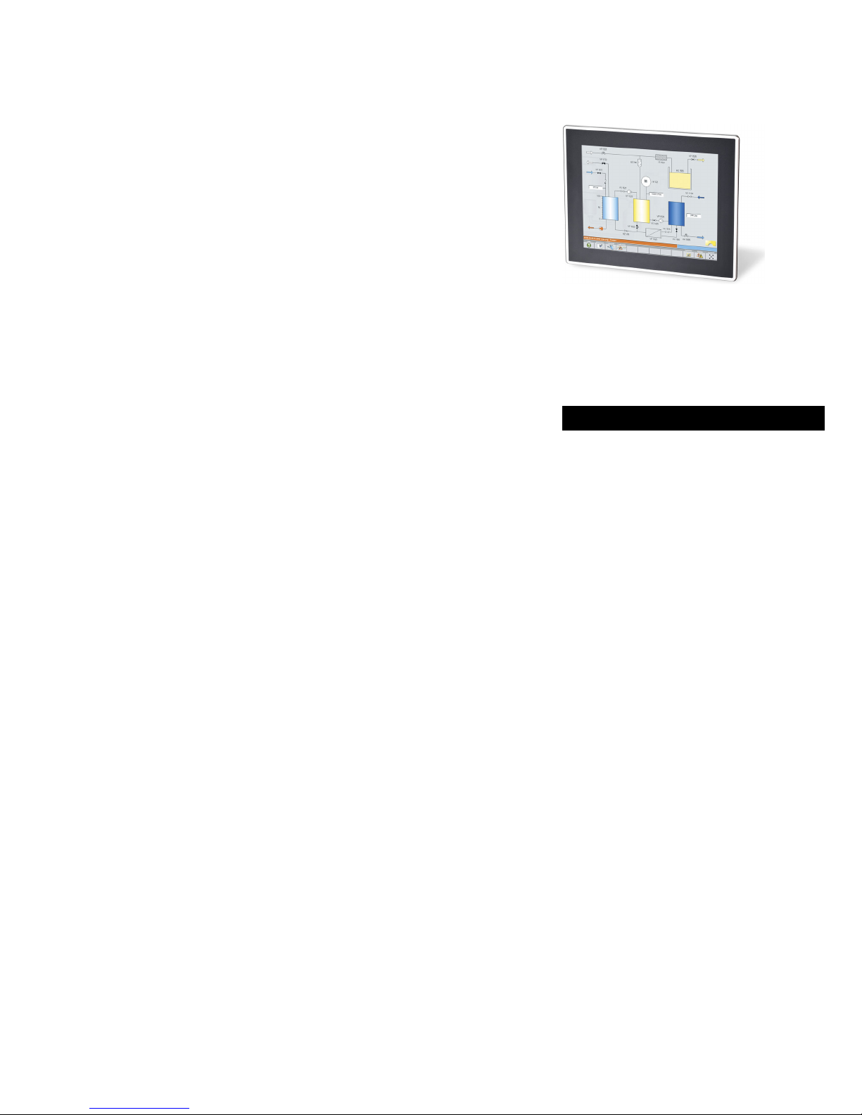
Panel Controller p500

Please read these instructions before you start working!
Follow the enclosed safety instructions.
Tip!
Information and tools concerning the Lenze products can be found in the download area under
www.lenze.com

Contents i
3
Lenze ¯ BA_p500 ¯ 3.0
1 About this documentation 5. . . . . . . . . . . . . . . . . . . . . . . . . . . . . . . . . . . . . . . . . . . . . . . . . . . . . . .
1.1 Document history 5. . . . . . . . . . . . . . . . . . . . . . . . . . . . . . . . . . . . . . . . . . . . . . . . . . . . . .
1.2 Conventions used 6. . . . . . . . . . . . . . . . . . . . . . . . . . . . . . . . . . . . . . . . . . . . . . . . . . . . . .
1.3 Notes used 7. . . . . . . . . . . . . . . . . . . . . . . . . . . . . . . . . . . . . . . . . . . . . . . . . . . . . . . . . . . .
2 Safety instructions 8. . . . . . . . . . . . . . . . . . . . . . . . . . . . . . . . . . . . . . . . . . . . . . . . . . . . . . . . . . . . . .
2.1 General safety information 8. . . . . . . . . . . . . . . . . . . . . . . . . . . . . . . . . . . . . . . . . . . . . .
2.2 Product−specific safety instructions 11. . . . . . . . . . . . . . . . . . . . . . . . . . . . . . . . . . . . . . .
2.3 Safety instructions for the installation according to UL/CSA 12. . . . . . . . . . . . . . . . . . .
3 Product description 14. . . . . . . . . . . . . . . . . . . . . . . . . . . . . . . . . . . . . . . . . . . . . . . . . . . . . . . . . . . . .
3.1 Scope of supply 14. . . . . . . . . . . . . . . . . . . . . . . . . . . . . . . . . . . . . . . . . . . . . . . . . . . . . . . .
3.2 Application as directed 15. . . . . . . . . . . . . . . . . . . . . . . . . . . . . . . . . . . . . . . . . . . . . . . . .
3.3 Device features 16. . . . . . . . . . . . . . . . . . . . . . . . . . . . . . . . . . . . . . . . . . . . . . . . . . . . . . . .
3.4 Identification 17. . . . . . . . . . . . . . . . . . . . . . . . . . . . . . . . . . . . . . . . . . . . . . . . . . . . . . . . . .
3.5 Controls and displays 19. . . . . . . . . . . . . . . . . . . . . . . . . . . . . . . . . . . . . . . . . . . . . . . . . . .
3.6 UPS functionality 21. . . . . . . . . . . . . . . . . . . . . . . . . . . . . . . . . . . . . . . . . . . . . . . . . . . . . . .
3.7 "Real Time Clock" functionality 21. . . . . . . . . . . . . . . . . . . . . . . . . . . . . . . . . . . . . . . . . . .
3.8 Resetting the device (Reset) 21. . . . . . . . . . . . . . . . . . . . . . . . . . . . . . . . . . . . . . . . . . . . . .
4 Technical data 22. . . . . . . . . . . . . . . . . . . . . . . . . . . . . . . . . . . . . . . . . . . . . . . . . . . . . . . . . . . . . . . . . .
4.1 General data and operating conditions 22. . . . . . . . . . . . . . . . . . . . . . . . . . . . . . . . . . .
4.2 Mechanical data 23. . . . . . . . . . . . . . . . . . . . . . . . . . . . . . . . . . . . . . . . . . . . . . . . . . . . . .
4.3 Electrical data 24. . . . . . . . . . . . . . . . . . . . . . . . . . . . . . . . . . . . . . . . . . . . . . . . . . . . . . . . . .
5 Mechanical installation 25. . . . . . . . . . . . . . . . . . . . . . . . . . . . . . . . . . . . . . . . . . . . . . . . . . . . . . . . . .
5.1 Important notes 25. . . . . . . . . . . . . . . . . . . . . . . . . . . . . . . . . . . . . . . . . . . . . . . . . . . . . . . .
5.2 Dimensions 26. . . . . . . . . . . . . . . . . . . . . . . . . . . . . . . . . . . . . . . . . . . . . . . . . . . . . . . . . . . .
5.3 Mounting steps 27. . . . . . . . . . . . . . . . . . . . . . . . . . . . . . . . . . . . . . . . . . . . . . . . . . . . . . . .

Contentsi
4
Lenze ¯ BA_p500 ¯ 3.0
6 Electrical installation 29. . . . . . . . . . . . . . . . . . . . . . . . . . . . . . . . . . . . . . . . . . . . . . . . . . . . . . . . . . . .
6.1 Important notes 29. . . . . . . . . . . . . . . . . . . . . . . . . . . . . . . . . . . . . . . . . . . . . . . . . . . . . . . .
6.2 EMC−compliant wiring 30. . . . . . . . . . . . . . . . . . . . . . . . . . . . . . . . . . . . . . . . . . . . . . . . . .
6.3 Connecting voltage supply (24 V) 31. . . . . . . . . . . . . . . . . . . . . . . . . . . . . . . . . . . . . . . . .
6.3.1 Connection plan 31. . . . . . . . . . . . . . . . . . . . . . . . . . . . . . . . . . . . . . . . . . . . . . .
6.3.2 Mains connection (24 V) 31. . . . . . . . . . . . . . . . . . . . . . . . . . . . . . . . . . . . . . . .
6.4 Interfaces for peripheral devices 32. . . . . . . . . . . . . . . . . . . . . . . . . . . . . . . . . . . . . . . . . .
6.4.1 Ethernet interface 32. . . . . . . . . . . . . . . . . . . . . . . . . . . . . . . . . . . . . . . . . . . . . .
6.4.2 EtherCAT interface 32. . . . . . . . . . . . . . . . . . . . . . . . . . . . . . . . . . . . . . . . . . . . .
6.4.3 USB interface 33. . . . . . . . . . . . . . . . . . . . . . . . . . . . . . . . . . . . . . . . . . . . . . . . . .
6.4.4 Communication interface (MC card) 33. . . . . . . . . . . . . . . . . . . . . . . . . . . . . .
6.4.5 SD card interface 33. . . . . . . . . . . . . . . . . . . . . . . . . . . . . . . . . . . . . . . . . . . . . . .
7 Maintenance 34. . . . . . . . . . . . . . . . . . . . . . . . . . . . . . . . . . . . . . . . . . . . . . . . . . . . . . . . . . . . . . . . . . .
7.1 Regular checks 34. . . . . . . . . . . . . . . . . . . . . . . . . . . . . . . . . . . . . . . . . . . . . . . . . . . . . . . . .
7.2 Cleaning 34. . . . . . . . . . . . . . . . . . . . . . . . . . . . . . . . . . . . . . . . . . . . . . . . . . . . . . . . . . . . . .
8 Index 35. . . . . . . . . . . . . . . . . . . . . . . . . . . . . . . . . . . . . . . . . . . . . . . . . . . . . . . . . . . . . . . . . . . . . . . . .

About this documentation
Document history
1
5
Lenze ¯ BA_p500 ¯ 3.0
0Fig. 0Tab. 0
1 About this documentation
Contents
This documentation provides you with information about the intended use of the Panel
Controller p500 in the Lenze "Controller−based Automation" control system.
Reference manual "Controller"
Here you can find detailed information on the parameter setting and
programming of the Lenze Controllers.
Target group
This documentation is directed at qualified skilled personnel according to IEC 60364.
Qualified skilled personnel are persons who have the required qualifications to carry out
all activities involved in installing, mounting, commissioning, and operating the
product.
1.1 Document history
Version Description
3.0 08/2014 TD17 ¯ EAC conformity supplemented
¯ General updates and corrections
¯ New layout
2.0 10/2013 TD06 General revision and UL approval
1.0 07/2012 TD29 First edition
About this documentation
Conventions used
1
6
Lenze ¯ BA_p500 ¯ 3.0
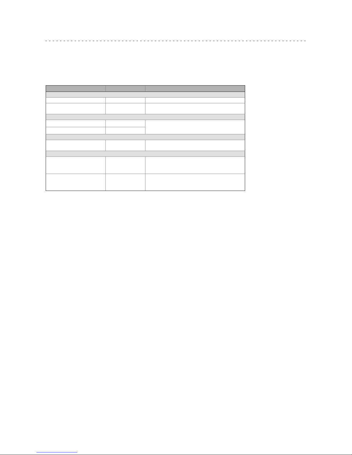
1.2 Conventions used
This documentation uses the following conventions to distinguish between different
types of information:
Type of information Writing Example/notes
Spelling of numbers
Decimal Normal spelling Example: 1234
Decimal separator Point The decimal point is always used.
For example: 1234.56
Warnings
UL warnings
Given in English and French
UR warnings
Text
Program name » « PC software
For example: Lenze »Engineer«
Icons
Page reference
Reference to another page with additional
information
For instance:
16 = see page 16
Documentation reference
Reference to another documentation with
additional information
Example:
EDKxxx = see documentation EDKxxx
EtherCAT
â
EtherCATâ is a registered trademark and patented technology licensed by Beckhoff
Automation GmbH, Germany.

About this documentation
Notes used
1
7
Lenze ¯ BA_p500 ¯ 3.0
1.3 Notes used
The following pictographs and signal words are used in this documentation to indicate
dangers and important information:
Safety instructions
Layout of the safety instructions:
Danger!
(characterises the type and severity of danger)
Note
(describes the danger and gives information about how to prevent
dangerous situations)
Pictograph and signal word Meaning
Danger!
Danger of personal injury through dangerous electrical
voltage
Reference to an imminent danger that may result in death
or serious personal injury if the corresponding measures are
not taken.
Danger!
Danger of personal injury through a general source of
danger
Reference to an imminent danger that may result in death
or serious personal injury if the corresponding measures are
not taken.
Stop!
Danger of property damage
Reference to a possible danger that may result in property
damage if the corresponding measures are not taken.
Application notes
Pictograph and signal word Meaning
Note!
Important note to ensure trouble−free operation
Tip!
Useful tip for easy handling
Reference to another document
Special safety instructions and application notes
Pictograph and signal word Meaning
Warnings!
Safety note or application note for the operation according
to UL or CSA requirements.
The measures are required to meet the requirements
according to UL or CSA.
Warnings!

Safety instructions
General safety information
2
8
Lenze ¯ BA_p500 ¯ 3.0
2 Safety instructions
2.1 General safety information
Scope
The following general safety instructions apply to all Lenze drive and automation
components.
The product−specific safety and application notes given in this documentation must be
observed!
For your own safety
Danger!
Disregarding the following basic safety measures may lead to severe
personal injury and damage to material assets!
¯ Lenze drive and automation components ...
... must only be used for the intended purpose.
... must never be operated if damaged.
... must never be subjected to technical modifications.
... must never be operated unless completely assembled.
... must never be operated without the covers/guards.
... can − depending on their degree of protection − have live, movable or rotating parts
during or after operation. Surfaces can be hot.
¯ For Lenze drive and automation components ...
... only use approved accessories.
... only use original manufacturer spare parts.
¯ All specifications of the corresponding enclosed documentation must be
observed.
This is vital for a safe and trouble−free operation and for achieving the specified
product features.
The procedural notes and circuit details provided in this document are proposals
which the user must check for suitability for his application. The manufacturer does
not accept any liability for the suitability of the specified procedures and circuit
proposals.
¯ Only qualified skilled personnel are permitted to work with or on Lenze drive and
automation components.
According to IEC 60364 or CENELEC HD 384, these are persons ...
... who are familiar with the installation, assembly, commissioning and operation of
the product,
... possess the appropriate qualifications for their work,
... and are acquainted with and can apply all the accident prevent regulations,
directives and laws applicable at the place of use.
Transport, storage
¯ Transport and storage in a dry, low−vibration environment without aggressive
atmosphere; preferably in the packaging provided by the manufacturer.
– Protect against dust and impacts.
– Observe climatic conditions according to the technical data.

Safety instructions
General safety information
2
9
Lenze ¯ BA_p500 ¯ 3.0
Mechanical installation
¯ Install the product according to the regulations of the corresponding
documentation. In particular observe the section "Operating conditions" in the
chapter "Technical data".
¯ Provide for a careful handling and avoid mechanical overload. During handling
neither bend components, nor change the insulation distances.
¯ The product contains electrostatic sensitive devices which can easily be damaged
by short circuit or static discharge (ESD). Thus, electronic components and
contacts must not be touched unless ESD measures are taken beforehand.
Electrical installation
¯ Carry out the electrical installation according to the relevant regulations (e. g.
cable cross−sections, fusing, connection to the PE conductor). Additional notes are
included in the documentation.
¯ When working on live products, observe the applicable national regulations for
the prevention of accidents (e.g. BGV 3).
¯ The Instructions contain notes concerning wiring according to EMC regulations
(shielding, earthing, filters and cable routing). The compliance with limit values
required by the EMC legislation is the responsibility of the manufacturer of the
machine or system.
Warning: The inverters are automation components which can be used in industrial
environment according to EN 61000−6−4. These products may cause radio
interference in residential areas. If this happens, the operator may need to take
appropriate action.
¯ For compliance with the limit values for radio interference emission at the site of
installation, the components − if specified in the technical data − have to be
mounted in housings (e. g. control cabinets). The housings have to enable an
EMC−compliant installation. In particular observe that for example control cabinet
doors preferably have a circumferential metallic connection to the housing.
Reduce openings or cutouts through the housing to a minimum.
¯ Only plug in or remove pluggable terminals in the deenergised state!
Commissioning
¯ If required, you have to equip the system with additional monitoring and
protective devices in accordance with the respective valid safety regulations (e. g.
law on technical equipment, regulations for the prevention of accidents).
Maintenance and servicing
¯ The components are maintenance−free if the required operating conditions are
observed.
¯ If the cooling air is polluted, the cooling surfaces may be contaminated or the air
vents may be blocked. Under these operating conditions, the cooling surfaces and
air vents must be cleaned at regular intervals. Never use sharp objects for this
purpose!
¯ After the system has been disconnected from the supply voltage, live components
and power connections must not be touched immediately because capacitors may
be charged. Please observe the corresponding notes on the device.

Safety instructions
General safety information
2
10
Lenze ¯ BA_p500 ¯ 3.0
Disposal
¯ Recycle or dispose of the product according to the applicable regulations.

Safety instructions
Product−specific safety instructions
2
11
Lenze ¯ BA_p500 ¯ 3.0
2.2 Product−specific safety instructions
¯ Protect the device against direct solar radiation, since the housing may heat up
strongly.
¯ The device is classified as a class A device and can cause radio interference in
residential areas. In this case, the operator may have to take special measures.
Any costs arising from these measures have to be paid by the operator.
¯ A touchscreen does not comply with the Ergonomics Directive ZH 1/618. This is
why it is only designed for short−time inputs and monitoring functions. For longer
inputs, connect an external keyboard.
¯ In the event of a fault, unplug the power connector immediately and send back
the device to the manufacturer. The address can be found on the self−addressed
envelope included in this documentation. Please use the original packaging to
return the device!
Stop!
The product contains electrostatic sensitive devices.
Before working in the connection area, the personnel must be free of
electrostatic charge.

Safety instructions
Safety instructions for the installation according to UL/CSA
2
12
Lenze ¯ BA_p500 ¯ 3.0
2.3 Safety instructions for the installation according to UL/CSA
Approval
Underwriter Laboratories (UL), UL 508 and CSA C22.2 No. 142−M1987 (UL File Number
E236341)
Ratings
¯ Input 24 V DC, max. 1.7 A
¯ Max. Surrounding temperature:
– P500 7.0": 55 °C, in vertical (landscape or portrait) mounting position only at
relative humidity of 60 % RH with a linear derating to 30 °C at 90 % RH.
– P500 10.4": 55 °C in vertical (landscape or portrait) mounting position only at a
relative humidity of 55 % RH with a linear derating to 40 °C at 90 % RH.
– P500 15.0": 55 °C in vertical (landscape or portrait) mounting position only at a
relative humidity of 45 % RH with a linear derating to 40 °C at 90 % RH.
¯ These devices are intended for mounting in the outer surface of an enclosure,
Type 1, 4 and 4X indoor use only.
Warnings!
Field Wiring Markings
Wiring Terminal MSTB 2.5/3−STF−5.08:
¯ Use 60° or 60/75 °C copper wire only.
¯ AWG 18 ... 12 (0.82 ... 3.3 mm
2
)
¯ Torque 5...7 lb−in (0.5 ... 0.6 Nm)
Device
¯ For use in a pollution degree 2 and controlled environment only.
¯ For use on a Flat Surface of a Type 1, 4 and 4x Indoor Use Only
Enclosure
Optional filed bus module
¯ Use only together with appropriate cable connectors, provided with
screws for securement and secure connector to avoid loosening.
 Loading...