

Page 1
.P!ô
Ä.P!ôä
Operating Instructions
EN
p500 P50GAP...
Panel Controller p500
Page 2

Please read these instructions before you start working!
Follow the enclosed safety instructions.
Tip!
Information and tools concerning the Lenze products can be found in the download area under
www.lenze.com
Page 3

Contents i
3
Lenze ¯ BA_p500 ¯ 3.0
1 About this documentation 5. . . . . . . . . . . . . . . . . . . . . . . . . . . . . . . . . . . . . . . . . . . . . . . . . . . . . . .
1.1 Document history 5. . . . . . . . . . . . . . . . . . . . . . . . . . . . . . . . . . . . . . . . . . . . . . . . . . . . . .
1.2 Conventions used 6. . . . . . . . . . . . . . . . . . . . . . . . . . . . . . . . . . . . . . . . . . . . . . . . . . . . . .
1.3 Notes used 7. . . . . . . . . . . . . . . . . . . . . . . . . . . . . . . . . . . . . . . . . . . . . . . . . . . . . . . . . . . .
2 Safety instructions 8. . . . . . . . . . . . . . . . . . . . . . . . . . . . . . . . . . . . . . . . . . . . . . . . . . . . . . . . . . . . . .
2.1 General safety information 8. . . . . . . . . . . . . . . . . . . . . . . . . . . . . . . . . . . . . . . . . . . . . .
2.2 Product−specific safety instructions 11. . . . . . . . . . . . . . . . . . . . . . . . . . . . . . . . . . . . . . .
2.3 Safety instructions for the installation according to UL/CSA 12. . . . . . . . . . . . . . . . . . .
3 Product description 14. . . . . . . . . . . . . . . . . . . . . . . . . . . . . . . . . . . . . . . . . . . . . . . . . . . . . . . . . . . . .
3.1 Scope of supply 14. . . . . . . . . . . . . . . . . . . . . . . . . . . . . . . . . . . . . . . . . . . . . . . . . . . . . . . .
3.2 Application as directed 15. . . . . . . . . . . . . . . . . . . . . . . . . . . . . . . . . . . . . . . . . . . . . . . . .
3.3 Device features 16. . . . . . . . . . . . . . . . . . . . . . . . . . . . . . . . . . . . . . . . . . . . . . . . . . . . . . . .
3.4 Identification 17. . . . . . . . . . . . . . . . . . . . . . . . . . . . . . . . . . . . . . . . . . . . . . . . . . . . . . . . . .
3.5 Controls and displays 19. . . . . . . . . . . . . . . . . . . . . . . . . . . . . . . . . . . . . . . . . . . . . . . . . . .
3.6 UPS functionality 21. . . . . . . . . . . . . . . . . . . . . . . . . . . . . . . . . . . . . . . . . . . . . . . . . . . . . . .
3.7 "Real Time Clock" functionality 21. . . . . . . . . . . . . . . . . . . . . . . . . . . . . . . . . . . . . . . . . . .
3.8 Resetting the device (Reset) 21. . . . . . . . . . . . . . . . . . . . . . . . . . . . . . . . . . . . . . . . . . . . . .
4 Technical data 22. . . . . . . . . . . . . . . . . . . . . . . . . . . . . . . . . . . . . . . . . . . . . . . . . . . . . . . . . . . . . . . . . .
4.1 General data and operating conditions 22. . . . . . . . . . . . . . . . . . . . . . . . . . . . . . . . . . .
4.2 Mechanical data 23. . . . . . . . . . . . . . . . . . . . . . . . . . . . . . . . . . . . . . . . . . . . . . . . . . . . . .
4.3 Electrical data 24. . . . . . . . . . . . . . . . . . . . . . . . . . . . . . . . . . . . . . . . . . . . . . . . . . . . . . . . . .
5 Mechanical installation 25. . . . . . . . . . . . . . . . . . . . . . . . . . . . . . . . . . . . . . . . . . . . . . . . . . . . . . . . . .
5.1 Important notes 25. . . . . . . . . . . . . . . . . . . . . . . . . . . . . . . . . . . . . . . . . . . . . . . . . . . . . . . .
5.2 Dimensions 26. . . . . . . . . . . . . . . . . . . . . . . . . . . . . . . . . . . . . . . . . . . . . . . . . . . . . . . . . . . .
5.3 Mounting steps 27. . . . . . . . . . . . . . . . . . . . . . . . . . . . . . . . . . . . . . . . . . . . . . . . . . . . . . . .
Page 4

Contentsi
4
Lenze ¯ BA_p500 ¯ 3.0
6 Electrical installation 29. . . . . . . . . . . . . . . . . . . . . . . . . . . . . . . . . . . . . . . . . . . . . . . . . . . . . . . . . . . .
6.1 Important notes 29. . . . . . . . . . . . . . . . . . . . . . . . . . . . . . . . . . . . . . . . . . . . . . . . . . . . . . . .
6.2 EMC−compliant wiring 30. . . . . . . . . . . . . . . . . . . . . . . . . . . . . . . . . . . . . . . . . . . . . . . . . .
6.3 Connecting voltage supply (24 V) 31. . . . . . . . . . . . . . . . . . . . . . . . . . . . . . . . . . . . . . . . .
6.3.1 Connection plan 31. . . . . . . . . . . . . . . . . . . . . . . . . . . . . . . . . . . . . . . . . . . . . . .
6.3.2 Mains connection (24 V) 31. . . . . . . . . . . . . . . . . . . . . . . . . . . . . . . . . . . . . . . .
6.4 Interfaces for peripheral devices 32. . . . . . . . . . . . . . . . . . . . . . . . . . . . . . . . . . . . . . . . . .
6.4.1 Ethernet interface 32. . . . . . . . . . . . . . . . . . . . . . . . . . . . . . . . . . . . . . . . . . . . . .
6.4.2 EtherCAT interface 32. . . . . . . . . . . . . . . . . . . . . . . . . . . . . . . . . . . . . . . . . . . . .
6.4.3 USB interface 33. . . . . . . . . . . . . . . . . . . . . . . . . . . . . . . . . . . . . . . . . . . . . . . . . .
6.4.4 Communication interface (MC card) 33. . . . . . . . . . . . . . . . . . . . . . . . . . . . . .
6.4.5 SD card interface 33. . . . . . . . . . . . . . . . . . . . . . . . . . . . . . . . . . . . . . . . . . . . . . .
7 Maintenance 34. . . . . . . . . . . . . . . . . . . . . . . . . . . . . . . . . . . . . . . . . . . . . . . . . . . . . . . . . . . . . . . . . . .
7.1 Regular checks 34. . . . . . . . . . . . . . . . . . . . . . . . . . . . . . . . . . . . . . . . . . . . . . . . . . . . . . . . .
7.2 Cleaning 34. . . . . . . . . . . . . . . . . . . . . . . . . . . . . . . . . . . . . . . . . . . . . . . . . . . . . . . . . . . . . .
8 Index 35. . . . . . . . . . . . . . . . . . . . . . . . . . . . . . . . . . . . . . . . . . . . . . . . . . . . . . . . . . . . . . . . . . . . . . . . .
Page 5

About this documentation
Document history
1
5
Lenze ¯ BA_p500 ¯ 3.0
0Fig. 0Tab. 0
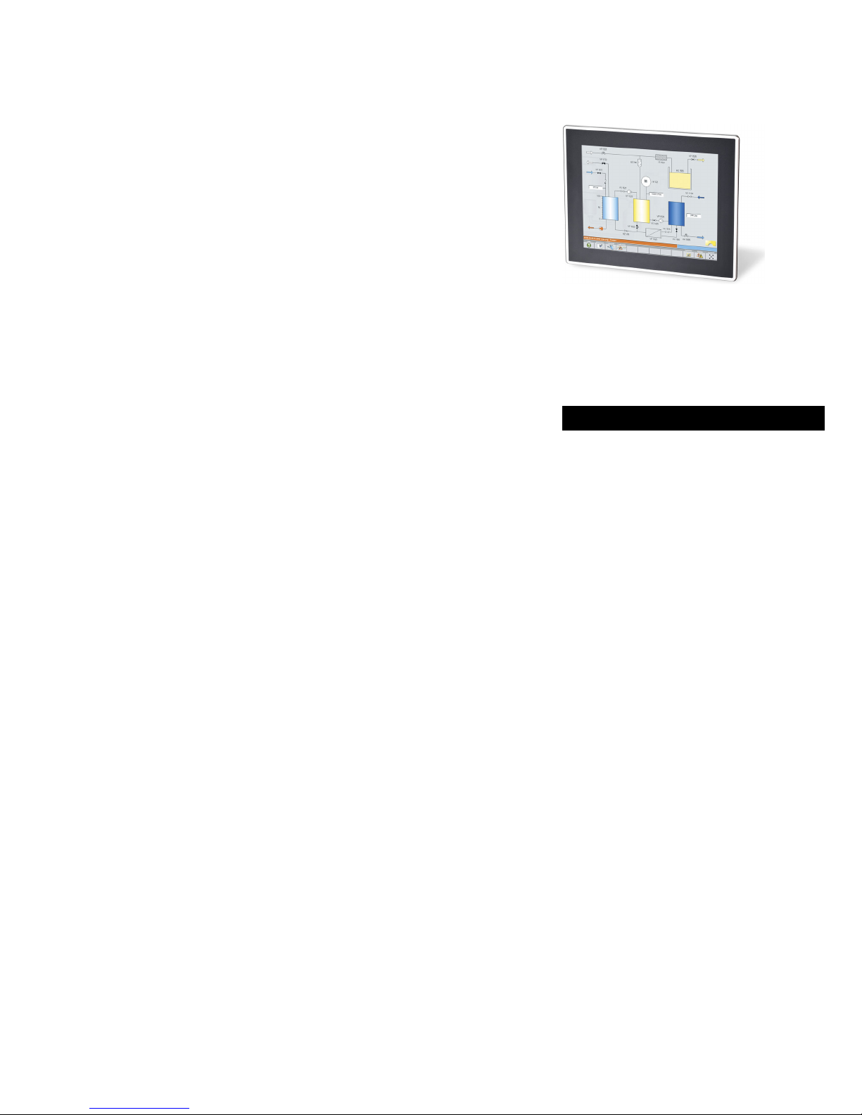
1 About this documentation
Contents
This documentation provides you with information about the intended use of the Panel
Controller p500 in the Lenze "Controller−based Automation" control system.
Reference manual "Controller"
Here you can find detailed information on the parameter setting and
programming of the Lenze Controllers.
Target group
This documentation is directed at qualified skilled personnel according to IEC 60364.
Qualified skilled personnel are persons who have the required qualifications to carry out
all activities involved in installing, mounting, commissioning, and operating the
product.
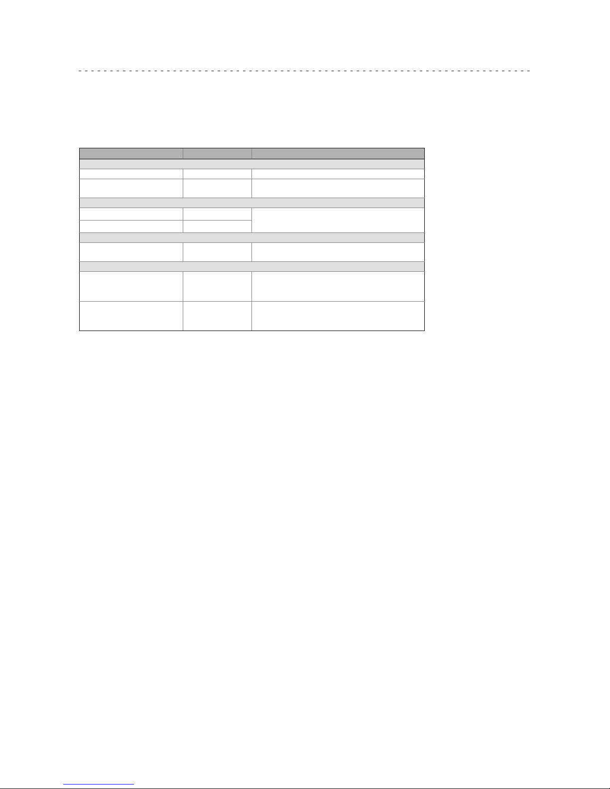
1.1 Document history
Version Description
3.0 08/2014 TD17 ¯ EAC conformity supplemented
¯ General updates and corrections
¯ New layout
2.0 10/2013 TD06 General revision and UL approval
1.0 07/2012 TD29 First edition
Page 6
About this documentation
Conventions used
1
6
Lenze ¯ BA_p500 ¯ 3.0
1.2 Conventions used
This documentation uses the following conventions to distinguish between different
types of information:
Type of information Writing Example/notes
Spelling of numbers
Decimal Normal spelling Example: 1234
Decimal separator Point The decimal point is always used.
For example: 1234.56
Warnings
UL warnings
Given in English and French
UR warnings
Text
Program name » « PC software
For example: Lenze »Engineer«
Icons
Page reference
Reference to another page with additional
information
For instance:
16 = see page 16
Documentation reference
Reference to another documentation with
additional information
Example:
EDKxxx = see documentation EDKxxx
EtherCAT
â
EtherCATâ is a registered trademark and patented technology licensed by Beckhoff
Automation GmbH, Germany.
Page 7

About this documentation
Notes used
1
7
Lenze ¯ BA_p500 ¯ 3.0
1.3 Notes used
The following pictographs and signal words are used in this documentation to indicate
dangers and important information:
Safety instructions
Layout of the safety instructions:
Danger!
(characterises the type and severity of danger)
Note
(describes the danger and gives information about how to prevent
dangerous situations)
Pictograph and signal word Meaning
Danger!
Danger of personal injury through dangerous electrical
voltage
Reference to an imminent danger that may result in death
or serious personal injury if the corresponding measures are
not taken.
Danger!
Danger of personal injury through a general source of
danger
Reference to an imminent danger that may result in death
or serious personal injury if the corresponding measures are
not taken.
Stop!
Danger of property damage
Reference to a possible danger that may result in property
damage if the corresponding measures are not taken.
Application notes
Pictograph and signal word Meaning
Note!
Important note to ensure trouble−free operation
Tip!
Useful tip for easy handling
Reference to another document
Special safety instructions and application notes
Pictograph and signal word Meaning
Warnings!
Safety note or application note for the operation according
to UL or CSA requirements.
The measures are required to meet the requirements
according to UL or CSA.
Warnings!
Page 8

Safety instructions
General safety information
2
8
Lenze ¯ BA_p500 ¯ 3.0
2 Safety instructions
2.1 General safety information
Scope
The following general safety instructions apply to all Lenze drive and automation
components.
The product−specific safety and application notes given in this documentation must be
observed!
For your own safety
Danger!
Disregarding the following basic safety measures may lead to severe
personal injury and damage to material assets!
¯ Lenze drive and automation components ...
... must only be used for the intended purpose.
... must never be operated if damaged.
... must never be subjected to technical modifications.
... must never be operated unless completely assembled.
... must never be operated without the covers/guards.
... can − depending on their degree of protection − have live, movable or rotating parts
during or after operation. Surfaces can be hot.
¯ For Lenze drive and automation components ...
... only use approved accessories.
... only use original manufacturer spare parts.
¯ All specifications of the corresponding enclosed documentation must be
observed.
This is vital for a safe and trouble−free operation and for achieving the specified
product features.
The procedural notes and circuit details provided in this document are proposals
which the user must check for suitability for his application. The manufacturer does
not accept any liability for the suitability of the specified procedures and circuit
proposals.
¯ Only qualified skilled personnel are permitted to work with or on Lenze drive and
automation components.
According to IEC 60364 or CENELEC HD 384, these are persons ...
... who are familiar with the installation, assembly, commissioning and operation of
the product,
... possess the appropriate qualifications for their work,
... and are acquainted with and can apply all the accident prevent regulations,
directives and laws applicable at the place of use.
Transport, storage
¯ Transport and storage in a dry, low−vibration environment without aggressive
atmosphere; preferably in the packaging provided by the manufacturer.
– Protect against dust and impacts.
– Observe climatic conditions according to the technical data.
Page 9

Safety instructions
General safety information
2
9
Lenze ¯ BA_p500 ¯ 3.0
Mechanical installation
¯ Install the product according to the regulations of the corresponding
documentation. In particular observe the section "Operating conditions" in the
chapter "Technical data".
¯ Provide for a careful handling and avoid mechanical overload. During handling
neither bend components, nor change the insulation distances.
¯ The product contains electrostatic sensitive devices which can easily be damaged
by short circuit or static discharge (ESD). Thus, electronic components and
contacts must not be touched unless ESD measures are taken beforehand.
Electrical installation
¯ Carry out the electrical installation according to the relevant regulations (e. g.
cable cross−sections, fusing, connection to the PE conductor). Additional notes are
included in the documentation.
¯ When working on live products, observe the applicable national regulations for
the prevention of accidents (e.g. BGV 3).
¯ The Instructions contain notes concerning wiring according to EMC regulations
(shielding, earthing, filters and cable routing). The compliance with limit values
required by the EMC legislation is the responsibility of the manufacturer of the
machine or system.
Warning: The inverters are automation components which can be used in industrial
environment according to EN 61000−6−4. These products may cause radio
interference in residential areas. If this happens, the operator may need to take
appropriate action.
¯ For compliance with the limit values for radio interference emission at the site of
installation, the components − if specified in the technical data − have to be
mounted in housings (e. g. control cabinets). The housings have to enable an
EMC−compliant installation. In particular observe that for example control cabinet
doors preferably have a circumferential metallic connection to the housing.
Reduce openings or cutouts through the housing to a minimum.
¯ Only plug in or remove pluggable terminals in the deenergised state!
Commissioning
¯ If required, you have to equip the system with additional monitoring and
protective devices in accordance with the respective valid safety regulations (e. g.
law on technical equipment, regulations for the prevention of accidents).
Maintenance and servicing
¯ The components are maintenance−free if the required operating conditions are
observed.
¯ If the cooling air is polluted, the cooling surfaces may be contaminated or the air
vents may be blocked. Under these operating conditions, the cooling surfaces and
air vents must be cleaned at regular intervals. Never use sharp objects for this
purpose!
¯ After the system has been disconnected from the supply voltage, live components
and power connections must not be touched immediately because capacitors may
be charged. Please observe the corresponding notes on the device.
Page 10

Safety instructions
General safety information
2
10
Lenze ¯ BA_p500 ¯ 3.0
Disposal
¯ Recycle or dispose of the product according to the applicable regulations.
Page 11

Safety instructions
Product−specific safety instructions
2
11
Lenze ¯ BA_p500 ¯ 3.0
2.2 Product−specific safety instructions
¯ Protect the device against direct solar radiation, since the housing may heat up
strongly.
¯ The device is classified as a class A device and can cause radio interference in
residential areas. In this case, the operator may have to take special measures.
Any costs arising from these measures have to be paid by the operator.
¯ A touchscreen does not comply with the Ergonomics Directive ZH 1/618. This is
why it is only designed for short−time inputs and monitoring functions. For longer
inputs, connect an external keyboard.
¯ In the event of a fault, unplug the power connector immediately and send back
the device to the manufacturer. The address can be found on the self−addressed
envelope included in this documentation. Please use the original packaging to
return the device!
Stop!
The product contains electrostatic sensitive devices.
Before working in the connection area, the personnel must be free of
electrostatic charge.
Page 12

Safety instructions
Safety instructions for the installation according to UL/CSA
2
12
Lenze ¯ BA_p500 ¯ 3.0
2.3 Safety instructions for the installation according to UL/CSA
Approval
Underwriter Laboratories (UL), UL 508 and CSA C22.2 No. 142−M1987 (UL File Number
E236341)
Ratings
¯ Input 24 V DC, max. 1.7 A
¯ Max. Surrounding temperature:
– P500 7.0": 55 °C, in vertical (landscape or portrait) mounting position only at
relative humidity of 60 % RH with a linear derating to 30 °C at 90 % RH.
– P500 10.4": 55 °C in vertical (landscape or portrait) mounting position only at a
relative humidity of 55 % RH with a linear derating to 40 °C at 90 % RH.
– P500 15.0": 55 °C in vertical (landscape or portrait) mounting position only at a
relative humidity of 45 % RH with a linear derating to 40 °C at 90 % RH.
¯ These devices are intended for mounting in the outer surface of an enclosure,
Type 1, 4 and 4X indoor use only.
Warnings!
Field Wiring Markings
Wiring Terminal MSTB 2.5/3−STF−5.08:
¯ Use 60° or 60/75 °C copper wire only.
¯ AWG 18 ... 12 (0.82 ... 3.3 mm
2
)
¯ Torque 5...7 lb−in (0.5 ... 0.6 Nm)
Device
¯ For use in a pollution degree 2 and controlled environment only.
¯ For use on a Flat Surface of a Type 1, 4 and 4x Indoor Use Only
Enclosure
Optional filed bus module
¯ Use only together with appropriate cable connectors, provided with
screws for securement and secure connector to avoid loosening.
Page 13

Safety instructions
Safety instructions for the installation according to UL/CSA
2
13
Lenze ¯ BA_p500 ¯ 3.0
Homologation
Underwriter Laboratories (UL), UL 508 et CSA C22.2 n° 142−M1987 (n° de dossier UL
E236341)
Caractéristiques assignées
¯ Entrée 24 V CC, maximum 1,7 A
¯ Température ambiante maximale :
– P500 7,0" : 55 °C sur un axe vertical uniquement (montage horizontal ou
vertical) pour 60 % RH d’humidité relative, réduction linéaire à 30 °C à 90 % RH
d’humidité.
– P500 10,4": 55 °C sur un axe vertical uniquement (montage horizontal ou
vertical) pour 55 % RH d’humidité relative, réduction linéaire à 40 °C à 90 % RH
d’humidité.
– P500 15,0": 55 °C sur un axe vertical uniquement (montage horizontal ou
vertical) pour 45 % RH d’humidité relative, réduction linéaire à 40 °C à 90 % RH
d’humidité.
¯ Ces équipements sont destinés à être montés sur la surface extérieure d’un
coffret de protection de types 1, 4 et 4X (usage intérieur exclusivement).
Warnings!
Marquage du câblage à pied d’oeuvre
Bornier de câblage MSTB 2,5/3−STF−5,08 :
¯ Utiliser exclusivement des conducteurs en cuivre 60 °C ou 60/75 °C.
¯ AWG 18 ... 12 (0.82 ... 3.3 mm
2
)
¯ Couple de 5 à 7 lb−in (0,5 ... 0,6 Nm)
Appareil
¯ Destiné uniquement à un environnement contrôlé caractérisé par le
degré de pollution 2.
¯ Conçu pour une utilisation sur une surface plane, coffret de type 1, 4 et
4x (usage intérieur uniquement).
Module bus en option
¯ A utiliser exclusivement avec des connecteurs de câble à vis adaptés.
Fixer les connecteurs pour éviter toute déconnexion.
Page 14

Product description
Scope of supply
3
14
Lenze ¯ BA_p500 ¯ 3.0
3 Product description
17.8 cm
26.4 cm
38.1 cm
p500_001
Fig. 3−1 Panel Controller p500
3.1 Scope of supply
Number Name
1 Panel Controller
4
8
10
Screw tensioner
For screen size 17.8 cm (7.0")
For screen size 26.4 cm (10.4")
For screen size 38.1 cm (15.0")
1 Connection plug for voltage supply
1 SD card (inserted)
1 Mounting instructions
Page 15

Product description
Application as directed
3
15
Lenze ¯ BA_p500 ¯ 3.0
3.2 Application as directed
The Controller is used as directed if it is solely used for implementing control and
operating concepts or for presenting information in usual industrial and commercial
fields. A different use, or one beyond these purposes, is not permissible.
A use that is not intended also includes a use harbouring fatal risks or dangers which,
without the provision of exceptionally high safety measures, may result in death, injury
or damage to material assets.
The Controller in particular must not be used ...
¯ in private areas
¯ in potentially explosive atmospheres
¯ in areas with harmful gases, oils, acids, radiation, etc.
¯ in applications where vibration and impact loads occur which exceed the
requirements of EN 61131−2.
¯ to execute safety functions, as for example
– in the air−traffic control/in flight control systems
– for monitoring/controlling nuclear reactions
– for monitoring/controlling mass transportation
– for monitoring/controlling medical systems
– for monitoring/controlling weapons systems
In order to ensure the protection of persons and material assets, higher−level safety
systems must be used!
Page 16

Product description
Device features
3
16
Lenze ¯ BA_p500 ¯ 3.0
3.3 Device features
Field Panel Controller p500
Design/mounting ¯ Sheet steel housing
¯ Front frame of anodised and etched aluminium
¯ Front film of polyester
¯ Installation in control cabinets, machine panels, and switchboards
¯ UPS function via internal capacitor
Screen
Diagonal 17.8 cm
(7.0")
26.4 cm
(10.4")
38.1 cm
(15.0")
Resolution 800 x 480 pixels
(WVGA)
800 x 600 pixels
(SVGA)
1024 x 768 pixels
(XGA)
Touchscreen ¯ Resistive single touch
¯ Anti−Newton ring design
¯ Surface hardness 3H
¯ Transmittance ~80 %
Processor type
Fanless
ATOMä , 1.6 GHz
512 kB L2−Cache
Memory
RAM 1 GB, DDR2−RAM
Read−only memory
(flash)
2 GB
SD/SDHC card 128 MB
Retain memory 128 kB
Interfaces
SD/SDHC card 1
Ethernet 2
EtherCAT 1
USB 2.0 2
Option
(MC card)
MC−CAN2 (CANopen master/slave)
MC−PBM (PROFIBUS master)
MC−PBS (PROFIBUS slave)
MC−PNC (PROFINET scanner)
MC−PND (PROFINET device)
MC−ISI (RS232, RS422, RS485)
Control/display elements
Reset key button ü
Diagnostic LEDs 4
Operating system
Windowsâ Embedded Compact 7
Runtime software
Logic ü
Motion ü
Visu
VisiWinNETâ Compact CE, 1000 power tags
Page 17

Product description
Identification
3
17
Lenze ¯ BA_p500 ¯ 3.0
3.4 Identification
How to find information
3
1
2
4
5
6
p500_002
Pos. Description
1 Windowsâ licence number
2 CODESYS licence number
3 Nameplate
4 MAC address LAN2 (EtherCAT)
5 MAC address LAN1a/b (Ethernet)
6 Terminal assignment
Nameplate
Input:
HW: SW:
Type:
32xxC_002
Fig. 3−2 Typenschild
Pos. Description
1 Manufacturer
2 Certification
3 Type designation
4 Technical data
5 Serial number as bar code and numerically
6 Material number (customer−specific)
7 Type code/order number
Page 18

Product description
Identification
3
18
Lenze ¯ BA_p500 ¯ 3.0
Type code
Type code
Panel Controller p500
P50GAP x 0300C4G x XXX−02S13 x 15 000
Screen size
4 = 26.4 cm (10.4")
6 = 38.1 cm (15.0")
9 = 17.8 cm (7.0")
MC card
0 = without
5 = MC−PBM (PROFIBUS master)
6 = MC−PBS (PROFIBUS slave)
7 = MC−PNC (PROFINET scanner)
8 = MC−PND (PROFINET device)
9 = MC−CAN2 (CANopen master/slave)
D = MC−ISI (RS232, RS422, RS485)
Control technology runtime software
3 = Logic: LPC1000 (V3.x)
4 = Motion: MPC1200 (V3.x)
Page 19

Product description
Controls and displays
3
19
Lenze ¯ BA_p500 ¯ 3.0
3.5 Controls and displays
X5 - USB
X4 - LAN 1a
X6 - USB
X3 - LAN 1b
X2 - EtherCAT
SD/SDHC
LEDs
Reset
X1 - Power
Reseved
p500−003
Fig. 3−3 Control and display elements
Pos. Description
A Touchscreen
B Panel Controller
C Slot for MC card (optional)
D Screw tensioner
Page 20

Product description
Controls and displays
3
20
Lenze ¯ BA_p500 ¯ 3.0
LED status displays
LED
Meaning
Power Error Status 1 Status 2
Flashing
blue
Off Off Off Supply voltage available and system clock synchronised.
Flashing
blue
Off Blinking
yellow
Off Operating system running and control technology (PLC
project) is started.
Flashing
blue
Blinking
red
Blinking
yellow
Off SD card not available/not inserted correctly.
Flashing
yellow
Off Off Off Input voltage has not reached a minimum value
(powerfail).
UPS function is triggered.
Blinking
yellow
Off Off Off State after switch−on/restart or a reset
Blinking
blue/
yellow
Off Off Off System clock not synchronised.
Off Off Off Off Reset has been triggered.
"Backup & Restore" software manual
Here you’ll find some detailed information relating to the LED status
displays of the optional "Backup & Restore" Engineering tools.
Page 21

Product description
UPS functionality
3
21
Lenze ¯ BA_p500 ¯ 3.0
3.6 UPS functionality
With the UPS functionality (uninterruptible power system), the device is provided with
a backup function. This means that, in the case of a supply voltage failure, the user data
(retain variables, logbook data) are saved before the device is switched off.
In order to minimise the power consumption during the buffer time and increase safety
during the buffer times, circuitry parts that are not required can be optionally switched
off if the supply voltage fails (e.g. backlight of the screen).
Panel Controller p500
UPS functionality via... Internal buffer capacitor
Storage medium for backup data SD/SDHC card
Buffer time sufficient for ... 128 kB of retain/logbook data
3.7 "Real Time Clock" functionality
The operating system is provided with the CMOS−RTC time via a maintenance−free clock
chip.
The CMOS−RTC time is stored internally for at least 28 days. Then the time must be reset
manually, e.g. via the »WebConfig« (parameter 91). A battery is not required.
3.8 Resetting the device (Reset)
To reset the device, press the reset button ( 19).
Two options are provided:
¯ Press the reset button for 4 ... 10 s:
– A reset of the complete system is carried out.
– All LEDs are off during the reset.
– After a successful reset, the POWER−LED is flashing blue.
¯ Press the reset button for more than 10 s:
– The Lenze standard setting is loaded and a restart is carried out.
– All LEDs are off during the reset.
– A backup image is loaded.
– After a successful reset, the POWER−LED is flashing blue.
Page 22

Technical data
General data and operating conditions
4
22
Lenze ¯ BA_p500 ¯ 3.0
4 Technical data
4.1 General data and operating conditions
General data
Conformity and approval
Conformity
CE 2004/108/EC EMC Directive
EAC TP TC 020/2011
(TR CU 020/2011)
Electromagnetic
compatibility of technical
means
Eurasian Conformity
TR CU: Technical Regulation of
Customs Union
Approval
UL UL 508
CSA C22.2
Process Control Equipment (File−No. E236341)
Other
RoHS 2011/65/EU Products are lead−free acc. to directive.
Protection of persons and device protection
Enclosure
Front panel EN 60529 IP65
Rear panel EN 60529 IP20
Electrical isolation
To the fieldbus Depending on the MC card used
To the process level None
Insulation resistance IEC 61131−2
Protective measures Against short circuit
EMC
Interference emission EN 61000−6−4 Class A (industrial premises)
Noise immunity EN 61000−6−2
Industrial premises
EN 61000−4−2 ESD; severity 3, i.e.
Air discharge: 8 kV,
4 kV with contact discharge
EN 61000−4−3 RF interference (housing)
80 MHz 1000 MHz, 10 V/m 80 % AM
(1 kHz)
EN 61000−4−4 Burst, severity level 3
EN 61000−4−5 Surge, severity 1
EN 61000−4−6 RF cable−guided
150 kHz 80 MHz, 10 V/m 80 % AM
(1 kHz)
Operating conditions
Ambient conditions
Climatic
Storage/transport EN 60721−3−2 2K3:
−25 ... +80 °C depending on the air humidity
(see diagrams 23)
Operation EN 60721−3−2 3K3:
0 ... +55 °C depending on the air humidity
(see diagrams 23)
Air humidity EN 60721−3−3 3K3 (without condensation, relative humidity 10 ... 95 %)
Pollution EN 61131−2 Degree of pollution 2
Mechanical
Vibration EN 61131−2 1 g
Shock EN 61131−2 15 g
Site altitude
Storage/transport < 12000 m amsl
Operation < 3000 m amsl
Page 23

Technical data
Mechanical data
4
23
Lenze ¯ BA_p500 ¯ 3.0
Panel Controller Diagrams regarding the air humidity/temperature
p500
17.8 cm (7.0")
0-10-20-30 10
20
30 40 50 60 70 80 °C
[%RH]
20
40
60
80
26.4 cm (10.4")
0-10-20-30 10
20
30 40 50 60 70 80 °C
[%RH]
20
40
60
80
38.1 cm (15.0")
0-10-20-30 10
20
30 40 50 60 70 80 °C
[%RH]
20
40
60
80
A During operation
B During storage/transport
Mounting conditions
Mounting place In the control cabinet, screen protected against direct solar radiation
Mounting position Connections to the sides or at the bottom
4.2 Mechanical data
Panel Controller
Dimensions Mass
1)
W x H x D [mm] [kg]
p500
17.8 cm (7.0") 210 x 155 x 86 1.4
26.4 cm (10.4") 263 x 221 x 86 2.5
38.1 cm (15.0") 371 x 291 x 93 4.5
1) Without MC card
Page 24

Technical data
Electrical data
4
24
Lenze ¯ BA_p500 ¯ 3.0
4.3 Electrical data
Panel Controller
Supply
Rated data
1)
Maximum
2)
Voltage Current Power Current Power
[V DC] [A] [W] [A] [W]
p500
17.8 cm (7.0")
24.0
(+18.0 ... +30.0)
0.5 12.0 1.2 28.8
26.4 cm (10.4") 0.6 14.4 1.3 31.2
38.1 cm (15.0") 0.7 16.8 1.5 36.0
1) For 24 V, without MC card (max. 0.25 A) and without USB consumer (max. 2 x 0.5 A)
2) For 24 V, full load, and during the boot/UPS loading phase (max. 30 s)
Screen display
Panel Controller
Format Resolution Number
Colours
Brightness Contrast BLT
1)
[pixels] [cd/m2] [h]
p500
17.8 cm (7.0") 15:9
800 x 480
(WVGA)
262144
320 1:400 20000
26.4 cm (10.4")
4:3
800 x 600
(SVGA)
400 1:700 50000
38.1 cm (15.0")
1024 x 768
(XGA)
1) Backlight Life Time
Page 25

Mechanical installation
Important notes
5
25
Lenze ¯ BA_p500 ¯ 3.0
5 Mechanical installation
5.1 Important notes
¯ To prevent damage to electronic components, only mount/remove the device
with the voltage supply switched off.
¯ The mounting location always must correspond to the operating conditions
specified in the technical data. If required, take additional measures.
¯ In the installation space, continuous and sufficient air circulation is absolutely
required to dissipate the heat of the device. The ventilation slots must not be
covered.
¯ When selecting the installation site, be sure to observe an ergonomic position of
the screen and pay regard to the incidence of light, which may cause reflections
on the screen.
¯ During installation, there is a danger that the controller will fall out of the
mounting cutout. You should therefore secure it to prevent this happening until
all screw clamps have been fitted.
¯ During mounting, the gasket of the front frame is exposed and can be damaged.
– Handle the gasket with care during mounting.
– Protect the gasket against ultraviolet rays.
– Check the gasket to make sure it is undamaged before you install the device.
¯ The device must be securely seated in the mounting cutout and the front panel
seal must be correctly fitted. Otherwise, class of protection IP65 will not be
achieved on the front side of the device!
Page 26

Mechanical installation
Dimensions
5
26
Lenze ¯ BA_p500 ¯ 3.0
5.2 Dimensions
a2
a1
a
e1
e3
b2
b1
b
e2
> 40
> 40
> 40 > 40
!
> 40
p500_004
Fig. 5−1 Dimensions and mounting clearances
Panel Controller
a a1 a2 b b1 b2 e1 e2 e3
[mm]
p500
17.8 cm (7.0") 210 191
182
155 136
104
82 4 22
26.4 cm (10.4") 282 263 240 221
38.1 cm (15.0") 390 371 310 291 87 6 27
Page 27

Mechanical installation
Mounting steps
5
27
Lenze ¯ BA_p500 ¯ 3.0
5.3 Mounting steps
1. Insert the panel controller into the mounting cutout.
1.
!
m
n
p500_006
Panel Controller
m n
[mm]
p500
17.8 cm (7.0") 194 139
26.4 cm (10.4") 266 224
38.1 cm (10.4") 374 294
Page 28

Mechanical installation
Mounting steps
5
28
Lenze ¯ BA_p500 ¯ 3.0
2. Use vice clamp.
2.
a
b
c
x
p500_007
x Positioning aid for screw clamps
3. Tighten the screws.
max. 20 Ncm
max. 1.7 lbin
3.
p500_008
Page 29

Electrical installation
Important notes
6
29
Lenze ¯ BA_p500 ¯ 3.0
6 Electrical installation
6.1 Important notes
The installation must be carried out by qualified, skilled personnel familiar with the
applicable national standards.
Stop!
Short circuit and static discharge
The device contains components which are endangered in the case of
short circuit or static discharge.
Possible consequences:
¯ The device or parts of it will be destroyed.
Protective measures:
¯ Always switch off the voltage supply when working on the device. This
particularly applies:
– Before connecting / disconnecting connectors.
– Before plugging in / plugging out modules.
¯ All persons handling printed circuit boards have to take account of ESD
measures.
¯ Contacts of plug connectors must not be touched.
¯ Printed circuit boards may be touched only at places free from
electrical contacts and may be placed only on appropriate materials
(e.g. on ESD packaging or conductive foam material).
¯ Printed circuit boards may only be transported and stored in ESD
packaging.
Page 30

Electrical installation
EMC−compliant wiring
6
30
Lenze ¯ BA_p500 ¯ 3.0
6.2 EMC−compliant wiring
Notes on EMC−compliant wiring
General notes ¯ The electromagnetic compatibility of the system depends on the type of installation
and care taken. Especially consider the following:
– Structure
– Shielding
– Earthing
¯ For installations differing from the one described, the evaluation of the conformity
with the EMC Directive requires a check of the system regarding the EMC limit
values. This for instance applies to:
– Use of unshielded cables
¯ The compliance with the EMC Directive is in the responsibility of the user.
– If you observe the following measures, you can assume that no EMC problems will
occur during operation and that compliance with the EMC Directive and the EMC
law is achieved.
– If devices which do not comply with the CE requirement concerning noise
immunity (EN 6100042) are operated close to the system, these devices may be
electromagnetically affected by the system.
Structure ¯ Provide electrical contact between the device and the earthed mounting plate:
– Mounting plates with conductive surfaces (zinc−coated, stainless steel) allow
permanent contact.
– Painted plates are not suitable for an EMC−compliant installation.
¯ If you use several mounting plates:
– Connect as much surface of the mounting plates as possible (e.g. with copper
strips).
¯ When laying the cables, pay attention to the separation of signal cables and mains
cables.
¯ Lay the cables as close as possible to the reference potential. Freely suspended cables
act like aerials.
Shielding ¯ Only use cables with braids if possible.
¯ The overlap rate of the shield should be higher than 80%.
¯ For data cables for serial connection, always use metal or metallised connectors.
Connect the shield of the data cable to the connector shell.
Earthing ¯ Earth all metallically conductive components using suitable cables connected to a
central earthing point (PE bar).
¯ Maintain the minimum cross−sections prescribed in the safety regulations:
– For the EMC, not the cable cross−section is important, but the surface and the
contact with a cross−section as large as possible, i.e. large surface.
Page 31

Electrical installation
Connecting voltage supply (24 V)
Connection plan
6
31
Lenze ¯ BA_p500 ¯ 3.0
6.3 Connecting voltage supply (24 V)
Stop!
No device protection against excessive input voltage
The voltage input is not fused internally.
Possible consequences:
¯ The device can be destroyed when the input voltage is too high.
Protective measures:
¯ Observe the max. permissible input voltage.
¯ Professionally fuse the device on the input side against voltage
fluctuations and voltage peaks.
Note!
The controller starts as soon as the supply voltage is applied.
After the operating system has been shut down, the controller switches
off automatically. For restarting, the supply voltage has to be
disconnected for a short time.
6.3.1 Connection plan
L1
N
PE
L1
N
+
0V
+24
+
~=
0V
PE +24 V
+
0
1
F
2
CPC2xx−006
Fig. 6−1 Connection plan for voltage supply (24 V)
Pos. Description
A
Panel Controller
B Power supply unit
C
PE conductor connection on the supply side (PE, bridged internally with GND)
6.3.2 Mains connection (24 V)
Figure Connection Connection type Cable type
0V U
X1:
DC voltage supply (24 V)
3−pin Combicon socket
Cable with Combicon plug
(conductor cross−section
max. 2.5 mm2)
IPC001
PE connection M4 (PH 2)
Separate earth conductor
(min. 2.5 mm
2
) with ring
cable lug
IPC001
Page 32

Electrical installation
Interfaces for peripheral devices
Ethernet interface
6
32
Lenze ¯ BA_p500 ¯ 3.0
6.4 Interfaces for peripheral devices
6.4.1 Ethernet interface
Figure Connection Connection type Cable type
X3 / X4:
Ethernet
X3 LAN1b (internal switch)
X4 LAN1a (internal switch)
RJ45 socket
Network cable
CAT5e S/FTP
(recommended)
Max. cable length 100 m
IPC001
The Controller can be connected to the higher−level network via X3 (LAN1b) or X4
(LAN1a). If the application comprises several Controllers, these can be networked in a
line network via the second LAN interface.
Baud rates: 10 or 100 Mbps
Note!
If the RJ45 plug connection is exposed to oscillating or vibrating stress:
¯ Use a strain relief in the immediate vicinity of the RJ45 socket.
¯ Select the contact surface on which the device is mounted as fixing
point of the strain relief.
¯ Comply with the related minimum bending radius of the cable used.
6.4.2 EtherCAT interface
Figure Connection Connection type Cable type
X2:
EtherCAT
RJ45 socket
Network cable
CAT5e S/FTP
(recommended)
Max. cable length 100 m
IPC001
Note!
If the RJ45 plug connection is exposed to oscillating or vibrating stress:
¯ Use a strain relief in the immediate vicinity of the RJ45 socket.
¯ Select the contact surface on which the device is mounted as fixing
point of the strain relief.
¯ Comply with the related minimum bending radius of the cable used.
Page 33

Electrical installation
Interfaces for peripheral devices
USB interface
6
33
Lenze ¯ BA_p500 ¯ 3.0
6.4.3 USB interface
Figure Connection Connection type Cable type
X5 / X6:
USB 2.0 connection
(max. load: 5 V/500 mA)
USB−A socket
USB cable with
USB−A plug
IPC001
6.4.4 Communication interface (MC card)
Figure Connection Connection type Cable type
Interface for optional
communication card (MC
card)
Socket connector −
EL100−013
6.4.5 SD card interface
Figure Connection Connection type Cable type
SD/SDHC card Slot −
Note!
The combination of control technology software and application data on
the SD card ensures that the data match the application in the present
version in each case. With the SD card, data in another device can be
easily replaced.
This makes it possible to avoid automatic update/downgrade processes
that are possibly undesirable and difficult to manage.
The SD card is used as flash memory for the following applications:
¯ PLC boot project (not for Lenze HMI devices)
¯ Visualisation
¯ Databases of the data manager
¯ prestart.txt/poststart.txt
¯ Retain and logbook data
¯ Customised data
The SD card is not bootable and must always be inserted!
How to exchange the SC card:
1. To unlock the SD card, press it carefully into the slot and release it.
2. Remove the SD card carefully.
3. Gently press the new SD card into the slot until it clicks into place.
Page 34

Maintenance
Regular checks
7
34
Lenze ¯ BA_p500 ¯ 3.0
7 Maintenance
7.1 Regular checks
The device is free of maintenance. Nevertheless, visual inspections should be carried out
at regular intervals which must not be too long, depending on the ambient conditions.
Please check the following:
¯ Does the environment of the device meet the operating conditions specified in
the Technical data?
¯ Is the heat dissipation of the device not impeded by dust or dirt?
¯ Are the mechanical and electrical connections o.k.?
7.2 Cleaning
Stop!
Sensitive surfaces and components
If not cleaned properly, the device may be damaged.
Possible consequences:
¯ The housing or the screen may be scratched or blunt if you use
alcoholic, solvent−containing or abrasive detergents.
¯ Electric components may be destroyed ...
– by a short circuit due to humidity.
– by static discharge.
Protective measures:
¯ Before cleaning, disconnect the device from the power supply as
otherwise unintentional commands may be activated via the
touchscreen.
¯ Clean the device front (screen and frame) as follows:
– Use a clean, soft and lint−free cloth.
– Only use water with a fluid addition as detergent or a detergent
declared especially for flat screens.
– Moisten the cloth with the detergent. Do not spray the detergent
directly on the device.
¯ Clean the rear side of the device with a clean, lintfree and soft cloth.
Do not use liquid or foaming detergent since it may enter the housing
or terminals.
Page 35

Index 8
35
Lenze ¯ BA_p500 ¯ 3.0
8 Index
0 ... 9
24 V connection, 31
A
Air humidity, 22
Air humidity/temperature
diagrams , 23
Ambient conditions
− air humidity/temperature diagrams,
23
− climatic, 22
− mechanical, 22
− site altitude, 22
Application as directed, 15
Approval, 22
C
Cleaning, 34
Communication interface (MC
card), 33
Conformity, 22
Connecting voltage supply (24 V),
31
Connection plan, 31
Controls, 19
D
Danger
− Short circuit, 29
− Static discharge, 29
Definition of notes used, 7
Device, radio interference, 11
Device features, 16
Device overview, 19
Device protection, 22
Diagnostic LED, 20
Dimensions, 23, 26
Displays, 19
Disposal, 10
E
Earthing (EMC−compliant wiring),
30
Electrical data, 24
Electrical installation, 29
− Communication interface (MC card),
33
− Connecting voltage supply (24 V), 31
− Connection plan for voltage supply,
31
− EMC−compliant wiring, 30
− EtherCAT interface, 32
− Ethernet interface, 32
− Important notes, 29
− Interfaces for peripheral devices, 32
− Mains connection (24 V), 31
− SD card interface, 33
− USB interface, 33
Electrical isolation, 22
EMC, 22
EMC−compliant wiring, 30
Enclosure, 22
Ergonomics, 11
Error behaviour, 11
EtherCAT interface, 32
Ethernet interface, 32
F
Fault, behaviour, 11
G
General data, 22
I
Identification, 17
Installation, electrical, 29
− Communication interface (MC card),
33
− Connecting voltage supply (24 V), 31
− Connection plan for voltage supply,
31
− EMC−compliant wiring, 30
− EtherCAT interface, 32
− Ethernet interface, 32
− Important notes, 29
− Interfaces for peripheral devices, 32
− Mains connection (24 V), 31
− SD card interface, 33
− USB interface, 33
Installation, mechanical, 25
− Dimensions and mounting
clearances, 26
Insulation resistance, 22
Interfaces for peripheral devices,
32
Interference emission, 22
L
LED status displays, 20
M
Mains connection (24 V), 31
Maintenance, 34
− Cleaning, 34
− Regular checks, 34
Mass, 23
Mechanical data, 23
Mechanical installation, 25
− Dimensions and mounting
clearances, 26
Mounting clearances, 26
Mounting conditions, 23
Mounting cutout, 27
Mounting place, 23
Mounting position, 23
Page 36

Index8
36
Lenze ¯ BA_p500 ¯ 3.0
N
Nameplate, 17
Noise immunity, 22
Notes, definition, 7
O
Operating conditions, 22
Operating temperature, 22
Overview of the control/display
elements, 19
P
Pollution, 22
Product description, 14
− application as directed, 15
Protection of persons, 22
Protective measures, 22
R
Radio interference, 11
Rated data, 24
Real Time Clock functionality, 21
Regular checks, 34
Reset, 21
Resetting the device (Reset), 21
S
Safety instructions, 8
− application as directed, 15
− definition, 7
− layout, 7
Scope of supply, 14
Screen display (technical data), 24
SD card interface, 33
shielding (EMC−compliant wiring),
30
Shock resistance, 22
Short circuit, 29
Static discharge, 29
Status LED, 20
Storage temperature, 22
structure (EMC−compliant wiring),
30
Supply, 24
T
Technical data, 22
− Electrical data, 24
− General data, 22
− mechanical data, 23
− Operating conditions, 22
− screen display, 24
Type code, finding, 17
U
UPS functionality, 21
USB interface, 33
V
Vibration resistance, 22
Voltage supply, 24
Page 37

© 08/2014 | BA_p500 | .P!ô | 3.0 | TD17
Lenze Automation GmbH
Postfach 10 13 52, D−31763 Hameln
Hans−Lenze−Str. 1, D−31855 Aerzen
Germany
+495154 82−0
+495154 82−2800
lenze@lenze.com
www.lenze.com
Lenze Service GmbH
Breslauer Straße 3, D−32699 Extertal
Germany
0080002446877 (24 h helpline)
+49515482−1112
service@lenze.com
10987654321
 Loading...