

Page 1
MA_ELx0xx
-
F3
Fail
Power
F1
+
F2
Status
Q+R
F1 F2 F5
-
S T
F3 F4
@\Z
F11F10YXF9F8 F12
WVU
F7F6
Shift
Alpha
Bs
Space
Enter
EscDel
Ins
Menu
Alt
Ctrl
Home
1
I
0
M
4
E
7
A
Pg Dn
*
3
J K L
/
,
N O P
Pg Up
End
Status
Power
Fail
2
.
+6
F G H
-
9
B C D
5
8
"
(
§
&
)
=
/
$
!
>
/
*
-
+
,
|
54 6
87 9
1 2 3
<
0
-
+
Alt Strg
*
+
T
F4
€
D
EWQ
XY
SA
@
F3F1 F2
R
VC
F
F5
G H J
-
_
Ä
F9F8F6 F7 F10
OI P ÜUZ
Ö
;
,
:
M
μ
.
LK
NB
Space
Enter
\?ß
~
F12
Esc
F11
Pos 1
Einfg
Ende
Entf
Bs
Alt Gr
Fail
Status
Power
Bild
Bild
S13
S14
S11
S10
S12
S6
S7
F3F2
+
-
F4
Status
Power
Fail
F1
Esc
Enter
F11 F12F6F5 F7 F8 F9 F10
S1
S4
S2
S3
S5
S8
S9
.NGE
L−force Controls
Montageanleitung
Mounting Instructions
Instructions de montage
Ä.NGEä
Instrucciones para el montaje
Istruzioni per il montaggio
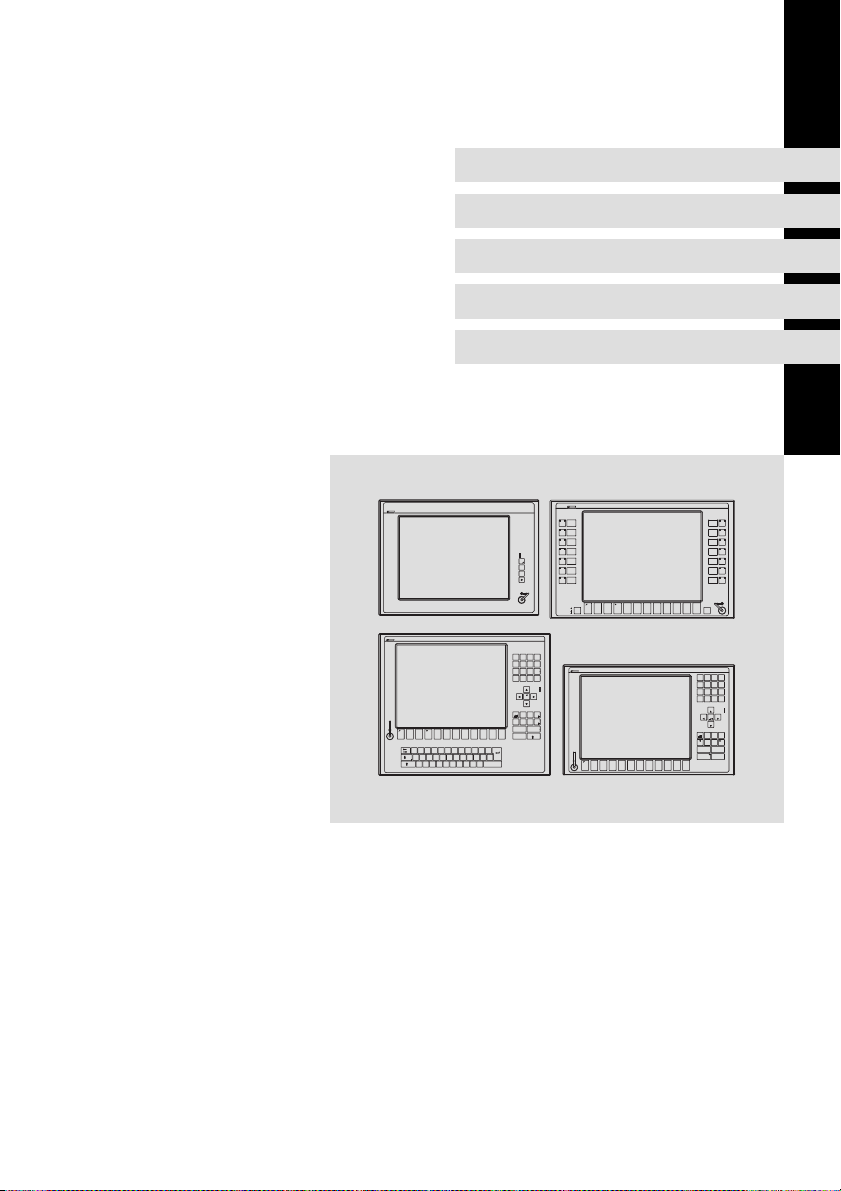
Industrial PC
Status
MP 800 DVI ... MP 9000 DVI
S1
S2
S3
S4
S5
S6
S7
Power
Status
S8
S9
S10
S11
S12
S13
S14
Enter
Power
Pg Up
Pg Dn
Ins
Ctrl
Shift
Space
Monitor Panel (Embedded Line)
Page 2

Lesen Sie zuerst diese Anleitung, bevor Sie mit den Arbeiten beginnen!
Beachten Sie die enthaltenen Sicherheitshinweise.
Ausführliche Informationen finden Sie in der Betriebsanleitung.
Read these instructions before you start working!
Follow the safety instructions given.
More detailed information can be found in the Operating Instructions.
Veuillez lire attentivement cette documentation avant toute action !
Les consignes de sécurité doivent impérativement être respectées.
Pour plus de détails, consulter les instructions de mise en service.
Lea estas instrucciones antes de empezar a trabajar.
Observe las instrucciones de seguridad indicadas.
El manual de instrucciones implica informaciónes detalladas.
Prima di iniziare qualsiasi intervento, leggere le presenti istruzioni.
Osservare le note di sicurezza.
Le istruzioni operative contengono informazioni dettagliati.
Page 3

Inhalt i
1 Über diese Dokumentation 4. . . . . . . . . . . . . . . . . . . . . . . . . . . . . . . . . . . . . . . . .
1.1 Verwendete Hinweise 4. . . . . . . . . . . . . . . . . . . . . . . . . . . . . . . . . . . . . . .
2 Sicherheitshinweise 5. . . . . . . . . . . . . . . . . . . . . . . . . . . . . . . . . . . . . . . . . . . . . . .
2.1 Sicherheitshinweise für die Installation nach UL 6. . . . . . . . . . . . . . . . .
3 Produktbeschreibung 9. . . . . . . . . . . . . . . . . . . . . . . . . . . . . . . . . . . . . . . . . . . . .
3.1 Lieferumfang 9. . . . . . . . . . . . . . . . . . . . . . . . . . . . . . . . . . . . . . . . . . . . . .
3.2 Bedien− und Anzeigeelemente 10. . . . . . . . . . . . . . . . . . . . . . . . . . . . . . . .
4 Installation 11. . . . . . . . . . . . . . . . . . . . . . . . . . . . . . . . . . . . . . . . . . . . . . . . . . . . . .
4.1 Wichtige Hinweise 11. . . . . . . . . . . . . . . . . . . . . . . . . . . . . . . . . . . . . . . . . .
4.2 Abmessungen 13. . . . . . . . . . . . . . . . . . . . . . . . . . . . . . . . . . . . . . . . . . . . . .
4.3 Einbauausschnitt 14. . . . . . . . . . . . . . . . . . . . . . . . . . . . . . . . . . . . . . . . . . .
4.4 Montageschritte 15. . . . . . . . . . . . . . . . . . . . . . . . . . . . . . . . . . . . . . . . . . .
4.4.1 MP 1000(s) DVI / MP 1050(s) DVI 15. . . . . . . . . . . . . . . . . . . . .
4.4.2 MP 2xxx DVI / MP 5xxx DVI / MP 9xxx DVI 16. . . . . . . . . . . . .
4.5 Elektrische Installation 18. . . . . . . . . . . . . . . . . . . . . . . . . . . . . . . . . . . . . .
MA_ELx0xx DE/EN/FR/ES/IT 2.0
3
Page 4
1
Über diese Dokumentation
Verwendete Hinweise
1 Über diese Dokumentation
0Abb. 0Tab. 0
1.1 Verwendete Hinweise
Um auf Gefahren und wichtige Informationen hinzuweisen, werden in dieser
Dokumentation folgende Piktogramme und Signalwörter verwendet:
Sicherheitshinweise
Aufbau der Sicherheitshinweise:
Gefahr!
(kennzeichnet die Art und die Schwere der Gefahr)
Hinweistext
(beschreibt die Gefahr und gibt Hinweise, wie sie vermieden werden
kann)
Piktogramm und Signalwort Bedeutung
Gefahr!
Gefahr!
Stop!
Anwendungshinweise
Gefahr von Personenschäden durch gefährliche elektrische Spannung
Hinweis auf eine unmittelbar drohende Gefahr, die den
Tod oder schwere Verletzungen zur Folge haben kann,
wenn nicht die entsprechenden Maßnahmen getroffen
werden.
Gefahr von Personenschäden durch eine allgemeine
Gefahrenquelle
Hinweis auf eine unmittelbar drohende Gefahr, die den
Tod oder schwere Verletzungen zur Folge haben kann,
wenn nicht die entsprechenden Maßnahmen getroffen
werden.
Gefahr von Sachschäden
Hinweis auf eine mögliche Gefahr, die Sachschäden zur
Folge haben kann, wenn nicht die entsprechenden Maßnahmen getroffen werden.
Piktogramm und Signalwort Bedeutung
Hinweis!
Tipp!
4
Wichtiger Hinweis für die störungsfreie Funktion
Nützlicher Tipp für die einfache Handhabung
Verweis auf andere Dokumentation
MA_ELx0xx DE/EN/FR/ES/IT 2.0
Page 5

2 Sicherheitshinweise
Auch zu Ihrer eigenen Sicherheit
Gefahr!
Wenn Sie die folgenden grundlegenden Sicherheitsmaßnahmen
missachten, kann dies zu schweren Personenschäden und
Sachschäden führen:
ƒ Lenze−Antriebs− und Automatisierungskomponenten ...
... ausschließlich bestimmungsgemäß verwenden.
... niemals trotz erkennbarer Schäden in Betrieb nehmen.
... niemals technisch verändern.
... niemals unvollständig montiert in Betrieb nehmen.
... niemals ohne erforderliche Abdeckungen betreiben.
... können während und nach dem Betrieb − ihrer Schutzart entsprechend −
spannungsführende, auch bewegliche oder rotierende Teile haben. Oberflächen können heiß sein.
ƒ Für Lenze−Antriebs− und Automatisierungskomponenten ...
... nur das zugelassene Zubehör verwenden.
... nur Original−Ersatzteile des Herstellers verwenden.
ƒ Alle Vorgaben der beiliegenden und zugehörigen Dokumentation
beachten.
Dies ist Voraussetzung für einen sicheren und störungsfreien Betrieb sowie
für das Erreichen der angegebenen Produkteigenschaften.
Die in diesem Dokument dargestellten verfahrenstechnischen Hinweise
und Schaltungsausschnitte sind Vorschläge, deren Übertragbarkeit auf die
jeweilige Anwendung überprüft werden muss. Für die Eignung der angegebenen Verfahren und Schaltungsvorschläge übernimmt der Hersteller keine
Gewähr.
ƒ Alle Arbeiten mit und an Lenze−Antriebs− und
Automatisierungskomponenten darf nur qualifiziertes Fachpersonal
ausführen.
Nach IEC 60364 bzw. CENELEC HD 384 sind dies Personen, ...
... die mit Aufstellung, Montage, Inbetriebsetzung und Betrieb des Produkts
vertraut sind.
... die über die entsprechenden Qualifikationen für ihre Tätigkeit verfügen.
... die alle am Einsatzort geltenden Unfallverhütungsvorschriften, Richtli-
nien und Gesetze kennen und anwenden können.
Sicherheitshinweise 2
MA_ELx0xx DE/EN/FR/ES/IT 2.0
5
Page 6

2
Sicherheitshinweise
Sicherheitshinweise für die Installation nach UL
2.1 Sicherheitshinweise für die Installation nach UL
Original − Englisch
Approval
Underwriter Laboratories (UL), UL508 and CSA C22.2 No. 142−M1987, (UL File
Number E236341)
Ratings
ƒ Input 24 V DC, 65 W
ƒ For use on an isolated power supply rated 24V DC 4A max.
ƒ Max. ambient temperature 40°C
ƒ Max. surrounding temperature 50 °C
ƒ Optional communication ratings:
– RS232−Connection (APL and DPL version only): max. 3 A
– USB−Connection (DVI version only): max. 1 A
– PS/2−Connection: max. 1 A
– VGA−Connection (APL version only): max. 4 A
– FBAS−Connection (APL version only): max. 4 A
– DVI−Connector (DVI version only): max. 4 A
– DPL−Connection (DVI version only): max. 4 A
– External Power Supply for DVI/USB Extender: max. 4 A
– Video−DSUB Connection for DVI/USB Extender: max. 4 A
– Data−DSUB Connection for DVI/USB Extender: max. 4 A
ƒ Environmental ratings: If these devices are mounted into a door or front
cover of an enclosure: Type 1 Enclosure.
Warnings!
Conditions of acceptability
ƒ These devices are for Type 1 front panel mounting only.
ƒ The external power supply connection is suitable for field wiring.
An isolated power supply rated 24 V DC, 4 A max. must be used.
Field Wiring Markings
Wiring Terminal MSTB 2,5/3−STF−5,08:
ƒ Use Copper Wire only.
ƒ AWG 18 ... AWG 12 (0.82 mm
ƒ Torque 5...7 lb−in (0.5 ... 0.6 Nm)
6
2
... 3.3 mm2)
MA_ELx0xx DE/EN/FR/ES/IT 2.0
Page 7

Sicherheitshinweise
Sicherheitshinweise für die Installation nach UL
Original − Französisch
Homologation
Underwriter Laboratories (UL), UL508 et CSA C22.2 n° 142−M1987, (n° de dossier
UL E236341)
2
MA_ELx0xx DE/EN/FR/ES/IT 2.0
7
Page 8

2
Sicherheitshinweise
Sicherheitshinweise für die Installation nach UL
Caractéristiques assignées
ƒ Entrée 24 V CC, 65 W
ƒ Equipement destiné à une alimentation avec isolation galvanique de 24V
CC, 4A maximum (tension assignée).
ƒ Température ambiante maximale : 40°C
ƒ Température ambiante maximale : 50 °C
ƒ Caractéristiques de communication assignées (option) :
– Port RS232 (versions APL et DPL uniquement) : maximum 3 A
– Port USB (version DVI uniquement) : maximum 1 A
– Port PS/2 : maximum 1 A
– Port VGA (version APL uniquement ) : maximum 4 A
– Port FBAS (version APL uniquement) : maximum 4 A
– Port DVI (version DVI uniquement) : maximum 4 A
– Port DPL (version DVI uniquement) : maximum 4 A
– Alimentation externe pour carte d’extension DVI/USB : maximum 4 A
– Port vidéo DSUB pour carte d’extension DVI/USB : maximum 4 A
– Port de données DSUB pour carte d’extension DVI/USB : maximum 4 A
ƒ Evaluations environnementales : en cas de montage des équipements
dans la porte ou le capot avant d’un coffret de protection : coffret de type
1.
Warnings!
Conditions of acceptability
ƒ Ces équipements sont conçus pour un montage de type 1 sur
panneau avant uniquement.
ƒ Le raccord d’alimentation externe est adapté à un câblage à pied
d’oeuvre. Utiliser impérativement une alimentation avec
isolation galvanique de 24V CC, 4A maximum (tension assignée).
Marquage du câblage à pied d’oeuvre
Bornier de câblage MSTB 2,5/3−STF−5,08 :
ƒ Utiliser exclusivement des conducteurs en cuivre.
ƒ AWG 18 ... AWG 12 (0,82 mm
ƒ Couple de 5 à 7 lb−in (0,5 ... 0,6 Nm)
8
2
... 3,3 mm2)
MA_ELx0xx DE/EN/FR/ES/IT 2.0
Page 9
3 Produktbeschreibung
3.1 Lieferumfang
Anzahl Bezeichnung
1 Monitor Panel
Schraubspanner
MP 800 DVI
8
MP 1000 DVI, MP 1000s DVI, MP 1050 DVI, MP 1050s DVI
8
MP 2000 DVI
4
MP 2050 DVI, MP 5000 DVI, MP 5020 DVI, MP 5050 DVI
6
MP 5070 DVI
5
MP 9000 DVI
6
1 Anschlussstecker für Spannungsversorgung
1 DVI−D−Kabel (Länge 2 m)
1 USB−Kabel (Länge 2 m)
1 DVD "PC based Automation"
1 Testbericht
1 Gerätepass
Produktbeschreibung
Lieferumfang
3
MA_ELx0xx DE/EN/FR/ES/IT 2.0
9
Page 10
3
Produktbeschreibung
Bedien− und Anzeigeelemente
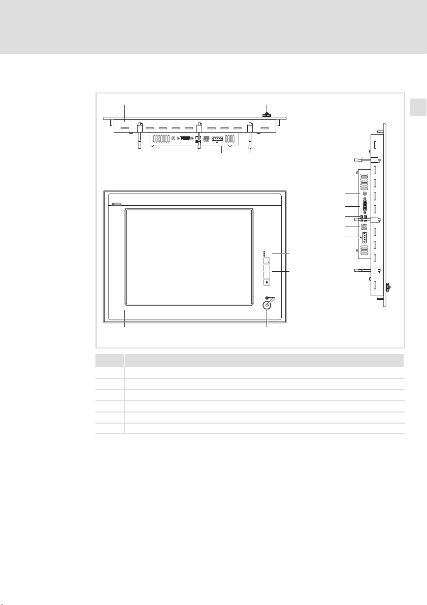
3.2 Bedien− und Anzeigeelemente
10
0V U
2
3
+
DVI
USB-A
USB-B
24 V DC
Power
Fail
Status
4
F1
F2
+
5
F3
-
0V U
10
0 1
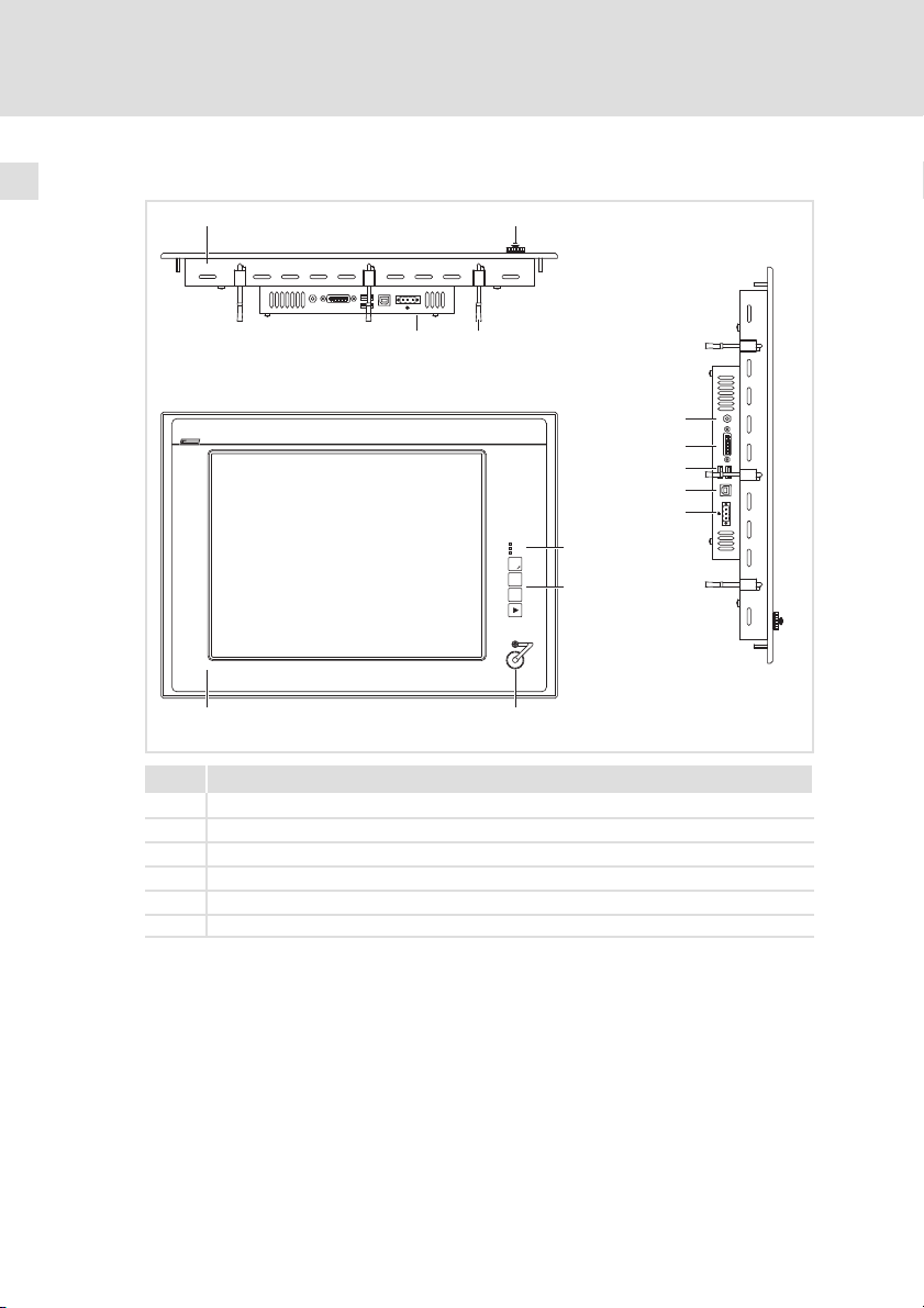
Pos. Beschreibung
Monitor Panel (hier MP 5000 DVI)
Frontseitiger USB−Anschluss (Option)
Schraubspanner
Typenschild
Status−LEDs (Power, Fail, Status)
Frontseitige Bedien− und Anzeigeelemente
MP9000DVI−001
MA_ELx0xx DE/EN/FR/ES/IT 2.0
Page 11

4 Installation
4.1 Wichtige Hinweise
Stop!
Empfindlicher Dichtring am Frontrahmen
Während der Montage liegt der Dichtring des Frontrahmens frei
und kann beschädigt werden.
Mögliche Folgen:
ƒ Die in den Technischen Daten genannte Schutzart wird nicht
erreicht.
Schutzmaßnahmen:
ƒ Gehen Sie während der Montage sorgsam mit dem Dichtring um.
ƒ Schützen Sie den Dichtring vor UV−Strahlen.
ƒ Kontrollieren Sie den Dichtring jedes Mal auf Unversehrtheit,
bevor Sie das Gerät montieren.
Installation
Wichtige Hinweise
4
MA_ELx0xx DE/EN/FR/ES/IT 2.0
11
Page 12

4
Installation
Wichtige Hinweise
Stop!
Kurzschluss und statische Entladungen
Das Gerät enthält Bauelemente, die bei Kurzschluss oder statischer
Entladung gefährdet sind.
Mögliche Folgen:
ƒ Das Gerät oder Teile davon werden zerstört.
Schutzmaßnahmen:
ƒ Bei allen Arbeiten am Gerät, immer Spannungsversorgung
abschalten. Dies gilt insbesondere:
– vor dem Anschließen / Abziehen von Steckverbindern.
– vor dem Stecken / Ziehen von Modulen.
ƒ Alle Personen, die Flachbaugruppen handhaben, müssen
ESD−Maßnahmen berücksichtigen.
ƒ Kontakte von Steckverbindern dürfen nicht berührt werden.
ƒ Flachbaugruppen dürfen nur an kontaktfreien Stellen angefasst
werden und nur auf geeigneten Unterlagen abgelegt werden
(z. B. auf ESD−Verpackung oder leitfähigem Schaumstoff).
ƒ Flachbaugruppen dürfen nur in ESD−Verpackungen transportiert
und gelagert werden.
12
MA_ELx0xx DE/EN/FR/ES/IT 2.0
Page 13
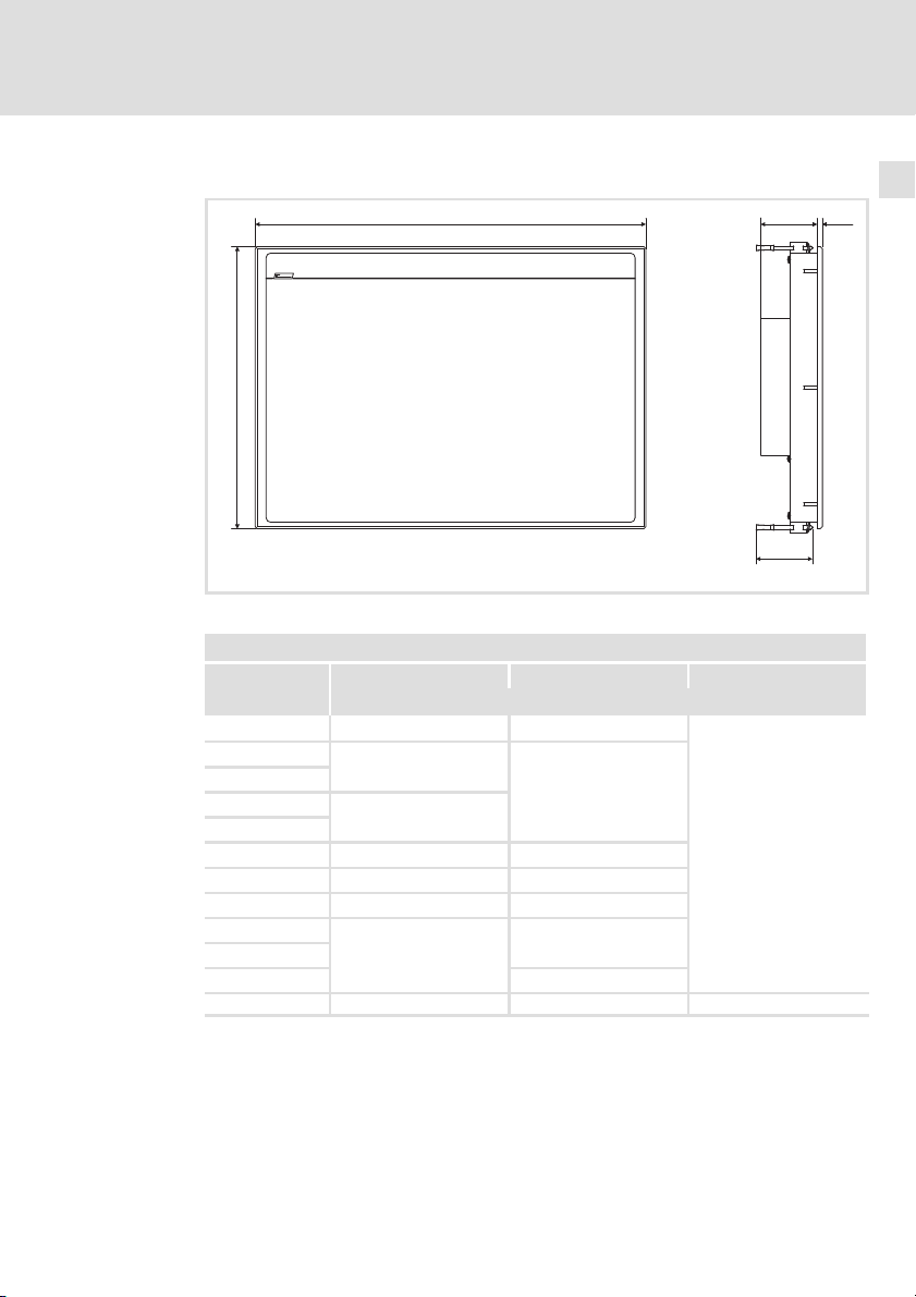
4.2 Abmessungen
Installation
Abmessungen
4
a
b
Alle Maße in Millimeter.
Abmessungen
a b e
[mm]
MP 800 DVI
MP 1000 DVI
MP 1000s DVI
MP 1050 DVI
MP 1050s DVI
MP 2000 DVI
MP 2050 DVI
MP 5000 DVI
MP 5020 DVI
MP 5050 DVI
MP 5070 DVI
MP 9000 DVI 490 400 69
265 200
325
240
365
390 300
425 310
450 325
483
310 (7 HE)
399 (9 HE)
6e
65
MP9000DVI−003
59
MA_ELx0xx DE/EN/FR/ES/IT 2.0
13
Page 14
4
Installation
Einbauausschnitt
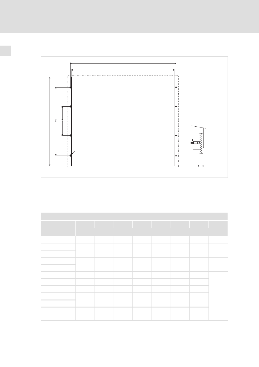
4.3 Einbauausschnitt
a2
a1
0
b3
b4
b1
b5
b2
D
Einbauausschnitt
Kontur Frontrahmen
Schalttafel
1
2
£ 5
ELx7xx−004
Alle Maße in Millimeter.
Abmessungen
a1 a2 b1 b2 b3 b4 b5 D
[mm]
MP 800 DVI 246 − 188 − − − − −
MP 1000 DVI
MP 1000s DVI
MP 1050 DVI
MP 1050s DVI
MP 2000 DVI
MP 2050 DVI
MP 5000 DVI
MP 5020 DVI
MP 5050 DVI
MP 5070 DVI
MP 9000 DVI 438.0 451.0 386.0 172.0 172.0 60.0 60.0 8 x Æ4.5
305.0 − 228.0 − − − − −
343.0 − 228.0 − − − − −
340.0 351.0 288.0 122.0 122.0 0.0 −
375.0 386.0 288.0 122.0 122.0 0.0 −
400.0 411.0 313.0 134.5 134.5 0.0 −
452.0 462.4 299.0 104.9 104.6 15.7 −
452.0 462.4 388.2 149.3 149.3 15.9 −
6 x Æ5.5
14
MA_ELx0xx DE/EN/FR/ES/IT 2.0
Page 15
4.4 Montageschritte
4.4.1 MP 1000(s) DVI / MP 1050(s) DVI
So gehen Sie bei der Montage vor:
1. Schneiden Sie den Einbauausschnitt in die Schalttafel ( 14).
2. Kontrollieren Sie, dass die Dichtung unter der Frontplatte korrekt liegt.
3. Setzen Sie das Gerät in den Einbauausschnitt, sichern Sie es mit einer
Hand gegen Herunterfallen.
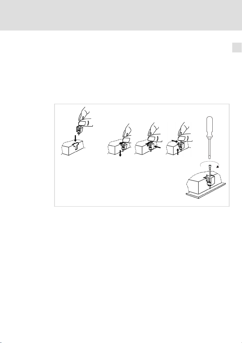
4. Montieren Sie alle Schraubspanner wie folgt:
Installation
Montageschritte
MP 1000(s) DVI / MP 1050(s) DVI
4
ELx7xx−011
– Stecken Sie den Schraubspanner, wie in der Abbildung gezeigt, in die
Öffnung am Gerätegehäuse.
– Drücken Sie den Schraubspanner nach unten, kippen Sie ihn in Richtung
Gehäuse und kontrollieren Sie, ob er korrekt eingerastet ist.
– Ziehen Sie den Schraubspanner mit einem Schraubendreher handfest
an.
5. Kontrollieren Sie, dass das Gerät fest im Einbauausschnitt sitzt und die
Frontplattendichtung korrekt aufliegt.
– Ggf. Gerät bzw. Dichtung neu ausrichten.
– Wenn die Dichtung nicht korrekt sitzt, wird auf der Gerätevorderseite
die Schutzklasse IP65 nicht erreicht!
MA_ELx0xx DE/EN/FR/ES/IT 2.0
15
Page 16
4
Installation
Montageschritte
MP 2xxx DVI / MP 5xxx DVI / MP 9xxx DVI
4.4.2 MP 2xxx DVI / MP 5xxx DVI / MP 9xxx DVI
Schalttafel−Montage
So gehen Sie bei der Montage vor:
1. Schneiden Sie den Einbauausschnitt in die Schalttafel und bohren Sie die
Befestigungslöcher in die Schalttafel ( 14).
2. Kontrollieren Sie, dass die Dichtung unter der Frontplatte korrekt liegt.
3. Setzen Sie das Gerät in den Einbauausschnitt, sichern Sie es mit einer
Hand gegen Herunterfallen und schrauben Sie Muttern mit Scheiben auf
die Gewindebolzen.
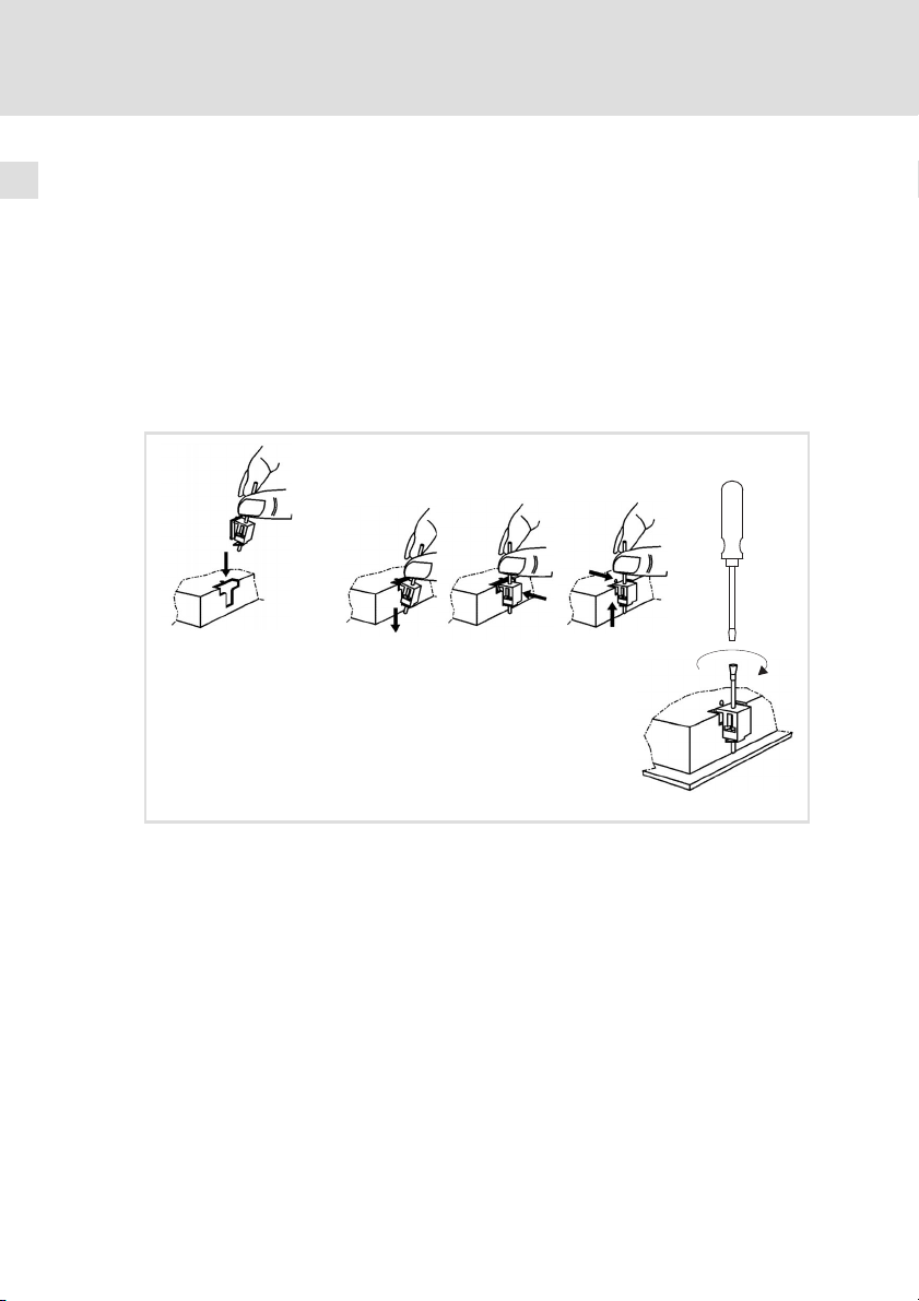
4. Montieren Sie alle Schraubspanner wie folgt:
16
ELx7xx−012
– Stecken Sie den Schraubspanner, wie in der Abbildung gezeigt, in die
Öffnung am Gerätegehäuse.
– Drücken Sie den Schraubspanner nach unten, kippen Sie ihn in Richtung
Gehäuse und kontrollieren Sie, ob er korrekt eingerastet ist.
– Ziehen Sie den Schraubspanner mit einem Schraubendreher handfest
an.
5. Kontrollieren Sie, dass das Gerät fest im Einbauausschnitt sitzt und die
Frontplattendichtung korrekt aufliegt.
– Ggf. Gerät bzw. Dichtung neu ausrichten.
– Wenn die Dichtung nicht korrekt sitzt, wird auf der Gerätevorderseite
die Schutzklasse IP65 nicht erreicht!
MA_ELx0xx DE/EN/FR/ES/IT 2.0
Page 17

Installation
Montageschritte
MP 2xxx DVI / MP 5xxx DVI / MP 9xxx DVI
Hinweis!
Die Typen MP 5020 DVI, MP 5050 DVI und MP 5070 DVI können
sowohl in beliebige Schalttafeln als auch in 19"−Baugruppenträger
nach DIN 41494 eingebaut werden.
19"−Baugruppenträger−Montage (nur MP 5020 DVI, MP 5050 DVI und MP
5070 DVI)
So gehen Sie bei der Montage vor:
1. Entfernen Sie am Frontrahmen die rückseitigen Gewindestifte.
2. Bohren Sie am Frontrahmen die rückseitigen Sacklöcher mit einem
6.5−mm−Bohrer auf.
3. Setzen Sie das Gerät in den 19"−Baugruppenträger und schrauben Sie es
fest.
4
MA_ELx0xx DE/EN/FR/ES/IT 2.0
17
Page 18
4
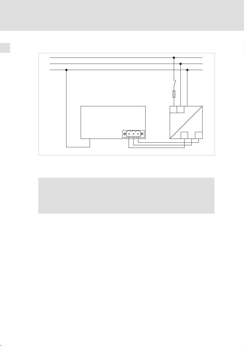
4.5 Elektrische Installation
Installation
Elektrische Installation
L1
N
PE
Monitor Panel
Netzteil
S
F
N
L1
0
+
~=
0V
PE +24 V
+
1
+
+24
0V
MP9000DVI−006
18
Hinweis!
Beachten Sie die maximal zulässige Eingangsspannung.
Sichern Sie das Gerät eingangsseitig fachgerecht gegen
Spannungsschwankungen und −spitzen ab.
MA_ELx0xx DE/EN/FR/ES/IT 2.0
Page 19

Installation
Elektrische Installation
4
MA_ELx0xx DE/EN/FR/ES/IT 2.0
19
Page 20

Contentsi
1 About this documentation 21. . . . . . . . . . . . . . . . . . . . . . . . . . . . . . . . . . . . . . . . . .
1.1 Notes used 21. . . . . . . . . . . . . . . . . . . . . . . . . . . . . . . . . . . . . . . . . . . . . . . .
2 Safety instructions 22. . . . . . . . . . . . . . . . . . . . . . . . . . . . . . . . . . . . . . . . . . . . . . . .
2.1 Safety instructions for the installation according to UL 23. . . . . . . . . . . .
3 Product description 26. . . . . . . . . . . . . . . . . . . . . . . . . . . . . . . . . . . . . . . . . . . . . . .
3.1 Scope of supply 26. . . . . . . . . . . . . . . . . . . . . . . . . . . . . . . . . . . . . . . . . . . .
3.2 Controls and displays 27. . . . . . . . . . . . . . . . . . . . . . . . . . . . . . . . . . . . . . . .
4 Installation 28. . . . . . . . . . . . . . . . . . . . . . . . . . . . . . . . . . . . . . . . . . . . . . . . . . . . . .
4.1 Important notes 28. . . . . . . . . . . . . . . . . . . . . . . . . . . . . . . . . . . . . . . . . . . .
4.2 Dimensions 30. . . . . . . . . . . . . . . . . . . . . . . . . . . . . . . . . . . . . . . . . . . . . . . .
4.3 Mounting cutout 31. . . . . . . . . . . . . . . . . . . . . . . . . . . . . . . . . . . . . . . . . . .
4.4 Mounting steps 32. . . . . . . . . . . . . . . . . . . . . . . . . . . . . . . . . . . . . . . . . . . .
4.4.1 MP 1000(s) DVI / MP 1050(s) DVI 32. . . . . . . . . . . . . . . . . . . . .
4.4.2 MP 2xxx DVI / MP 5xxx DVI / MP 9xxx DVI 33. . . . . . . . . . . . .
4.5 Electrical installation 35. . . . . . . . . . . . . . . . . . . . . . . . . . . . . . . . . . . . . . . .
20
MA_ELx0xx DE/EN/FR/ES/IT 2.0
Page 21
About this documentation
Notes used
1
1 About this documentation
0Fig. 0Tab. 0
1.1 Notes used
The following pictographs and signal words are used in this documentation to
indicate dangers and important information:
Safety instructions
Structure of safety instructions:
Danger!
(characterises the type and severity of danger)
Note
(describes the danger and gives information about how to prevent
dangerous situations)
Pictograph and signal word Meaning
Danger!
Danger!
Stop!
Application notes
Danger of personal injury through dangerous electrical
voltage.
Reference to an imminent danger that may result in
death or serious personal injury if the corresponding
measures are not taken.
Danger of personal injury through a general source of
danger.
Reference to an imminent danger that may result in
death or serious personal injury if the corresponding
measures are not taken.
Danger of property damage.
Reference to a possible danger that may result in
property damage if the corresponding measures are not
taken.
Pictograph and signal word Meaning
Note!
Tip!
MA_ELx0xx DE/EN/FR/ES/IT 2.0
Important note to ensure troublefree operation
Useful tip for simple handling
Reference to another documentation
21
Page 22

Safety instructions2
2 Safety instructions
For your own safety
Danger!
Disregarding the following basic safety measures may lead to
severe personal injury and damage to material assets!
ƒ Lenze drive and automation components ...
... must only be used for the intended purpose.
... must never be operated if damaged.
... must never be subjected to technical modifications.
... must never be operated unless completely assembled.
... must never be operated without the covers/guards.
... can − depending on their degree of protection − have live, movable or
rotating parts during or after operation. Surfaces can be hot.
ƒ For Lenze drive and automation components ...
... only use approved accessories.
... only use original manufacturer spare parts.
ƒ All specifications of the corresponding enclosed documentation must be
observed.
This is vital for a safe and trouble−free operation and for achieving the
specified product features.
The procedural notes and circuit details provided in this document are
proposals which the user must check for suitability for his application. The
manufacturer does not accept any liability for the suitability of the specified
procedures and circuit proposals.
ƒ Only qualified skilled personnel are permitted to work with or on Lenze
drive and automation components.
According to IEC 60364 or CENELEC HD 384, these are persons ...
... who are familiar with the installation, assembly, commissioning and
operation of the product,
... possess the appropriate qualifications for their work,
... and are acquainted with and can apply all the accident prevent
regulations, directives and laws applicable at the place of use.
22
MA_ELx0xx DE/EN/FR/ES/IT 2.0
Page 23

Safety instructions
Safety instructions for the installation according to UL
2
2.1 Safety instructions for the installation according to UL
Original − English
Approval
Underwriter Laboratories (UL), UL508 and CSA C22.2 No. 142−M1987, (UL File
Number E236341)
Ratings
ƒ Input 24 V DC, 65 W
ƒ For use on an isolated power supply rated 24V DC 4A max.
ƒ Max. ambient temperature 40°C
ƒ Max. surrounding temperature 50 °C
ƒ Optional communication ratings:
– RS232−Connection (APL and DPL version only): max. 3 A
– USB−Connection (DVI version only): max. 1 A
– PS/2−Connection: max. 1 A
– VGA−Connection (APL version only): max. 4 A
– FBAS−Connection (APL version only): max. 4 A
– DVI−Connector (DVI version only): max. 4 A
– DPL−Connection (DVI version only): max. 4 A
– External Power Supply for DVI/USB Extender: max. 4 A
– Video−DSUB Connection for DVI/USB Extender: max. 4 A
– Data−DSUB Connection for DVI/USB Extender: max. 4 A
ƒ Environmental ratings: If these devices are mounted into a door or front
cover of an enclosure: Type 1 Enclosure.
Warnings!
Conditions of acceptability
ƒ These devices are for Type 1 front panel mounting only.
ƒ The external power supply connection is suitable for field wiring.
Field Wiring Markings
Wiring Terminal MSTB 2,5/3−STF−5,08:
ƒ Use Copper Wire only.
ƒ AWG 18 ... AWG 12 (0.82 mm
ƒ Torque 5...7 lb−in (0.5 ... 0.6 Nm)
MA_ELx0xx DE/EN/FR/ES/IT 2.0
An isolated power supply rated 24 V DC, 4 A max. must be used.
2
... 3.3 mm2)
23
Page 24

2
Safety instructions
Safety instructions for the installation according to UL
Original − French
Homologation
Underwriter Laboratories (UL), UL508 et CSA C22.2 n° 142−M1987, (n° de dossier
UL E236341)
24
MA_ELx0xx DE/EN/FR/ES/IT 2.0
Page 25

Safety instructions
Safety instructions for the installation according to UL
Caractéristiques assignées
ƒ Entrée 24 V CC, 65 W
ƒ Equipement destiné à une alimentation avec isolation galvanique de 24V
CC, 4A maximum (tension assignée).
ƒ Température ambiante maximale : 40°C
ƒ Température ambiante maximale : 50 °C
ƒ Caractéristiques de communication assignées (option) :
– Port RS232 (versions APL et DPL uniquement) : maximum 3 A
– Port USB (version DVI uniquement) : maximum 1 A
– Port PS/2 : maximum 1 A
– Port VGA (version APL uniquement ) : maximum 4 A
– Port FBAS (version APL uniquement) : maximum 4 A
– Port DVI (version DVI uniquement) : maximum 4 A
– Port DPL (version DVI uniquement) : maximum 4 A
– Alimentation externe pour carte d’extension DVI/USB : maximum 4 A
– Port vidéo DSUB pour carte d’extension DVI/USB : maximum 4 A
– Port de données DSUB pour carte d’extension DVI/USB : maximum 4 A
ƒ Evaluations environnementales : en cas de montage des équipements
dans la porte ou le capot avant d’un coffret de protection : coffret de type
1.
2
Warnings!
Conditions of acceptability
ƒ Ces équipements sont conçus pour un montage de type 1 sur
ƒ Le raccord d’alimentation externe est adapté à un câblage à pied
Marquage du câblage à pied d’oeuvre
Bornier de câblage MSTB 2,5/3−STF−5,08 :
ƒ Utiliser exclusivement des conducteurs en cuivre.
ƒ AWG 18 ... AWG 12 (0,82 mm
ƒ Couple de 5 à 7 lb−in (0,5 ... 0,6 Nm)
MA_ELx0xx DE/EN/FR/ES/IT 2.0
panneau avant uniquement.
d’oeuvre. Utiliser impérativement une alimentation avec
isolation galvanique de 24V CC, 4A maximum (tension assignée).
2
... 3,3 mm2)
25
Page 26
3
Product description
Scope of supply
3 Product description
3.1 Scope of supply
Quantity Name
1 Monitor panel
Screw clamp fixings
MP 800 DVI
8
MP 1000 DVI, MP 1000s DVI, MP 1050 DVI, MP 1050s DVI
8
MP 2000 DVI
4
MP 2050 DVI, MP 5000 DVI, MP 5020 DVI, MP 5050 DVI
6
MP 5070 DVI
5
MP 9000 DVI
6
1 Connection plug for voltage supply
1 DVI−D cable (length 2 m)
1 USB cable (length 2 m)
1 DVD "PC based Automation"
1 Test report
1 Device pass card
26
MA_ELx0xx DE/EN/FR/ES/IT 2.0
Page 27
3.2 Controls and displays
Product description
3
Controls and displays
10
0V U
2
3
+
DVI
USB-A
USB-B
24 V DC
Power
Fail
Status
4
F1
F2
+
5
F3
-
0V U
0 1
Pos. Description
Monitor panel (here MP 5000 DVI)
Front face USB port (option)
Screw clamp fixings
Nameplate
Status LEDs (Power, Fail, Status)
Front face control and display elements
MA_ELx0xx DE/EN/FR/ES/IT 2.0
MP9000DVI−001
27
Page 28

4
Installation
Important notes
4 Installation
4.1 Important notes
Stop!
Sensitive front frame gasket
During mounting, the gasket of the front frame is exposed and can
be damaged.
Possible consequences:
ƒ The degree of protection provided by the enclosure mentioned in
the technical data is not attained.
Protective measures:
ƒ Handle the gasket with care during mounting.
ƒ Protect the gasket against ultraviolet rays.
ƒ Each time before you mount the device, check whether the
gasket is intact.
28
MA_ELx0xx DE/EN/FR/ES/IT 2.0
Page 29

Installation
Important notes
Stop!
Short circuit and static discharge
The device contains components which are endangered in the case
of short circuit or static discharge.
Possible consequences:
ƒ The device or parts of it will be destroyed.
Protective measures:
ƒ Always switch off the voltage supply when working on the
device. This particularly applies:
– Before connecting / disconnecting connectors.
– Before plugging in / plugging out modules.
ƒ All persons handling printed circuit boards have to take account
of ESD measures.
ƒ Contacts of plug connectors must not be touched.
ƒ Printed circuit boards may be touched only at places free from
electrical contacts and may be placed only on appropriate
materials (e.g. on ESD packaging or conductive foam material).
ƒ Printed circuit boards may only be transported and stored in ESD
packaging.
4
MA_ELx0xx DE/EN/FR/ES/IT 2.0
29
Page 30

4
Installation
Dimensions
4.2 Dimensions
a
b
All dimensions in millimetres.
Dimensions
a b e
[mm]
MP 800 DVI
MP 1000 DVI
MP 1000s DVI
MP 1050 DVI
MP 1050s DVI
MP 2000 DVI
MP 2050 DVI
MP 5000 DVI
MP 5020 DVI
MP 5050 DVI
MP 5070 DVI
MP 9000 DVI 490 400 69
265 200
325
240
365
390 300
425 310
450 325
483
310 (7 U)
399 (9 U)
6e
65
MP9000DVI−003
59
30
MA_ELx0xx DE/EN/FR/ES/IT 2.0
Page 31

4.3 Mounting cutout
b3
b4
b1
b5
b2
a2
a1
Installation
Mounting cutout
1
0
4
D
Mounting cutout
Outline of front panel
Control board
2
£ 5
ELx7xx−004
All dimensions in millimetres.
Dimensions
a1 a2 b1 b2 b3 b4 b5 D
[mm]
MP 800 DVI 246 − 188 − − − − −
MP 1000 DVI
MP 1000s DVI
MP 1050 DVI
MP 1050s DVI
MP 2000 DVI
MP 2050 DVI
MP 5000 DVI
MP 5020 DVI
MP 5050 DVI
MP 5070 DVI
MP 9000 DVI 438.0 451.0 386.0 172.0 172.0 60.0 60.0 8 x Æ4.5
305.0 − 228.0 − − − − −
343.0 − 228.0 − − − − −
340.0 351.0 288.0 122.0 122.0 0.0 −
375.0 386.0 288.0 122.0 122.0 0.0 −
400.0 411.0 313.0 134.5 134.5 0.0 −
452.0 462.4 299.0 104.9 104.6 15.7 −
452.0 462.4 388.2 149.3 149.3 15.9 −
6 x Æ5.5
MA_ELx0xx DE/EN/FR/ES/IT 2.0
31
Page 32

4
4.4 Mounting steps
4.4.1 MP 1000(s) DVI / MP 1050(s) DVI
Installation
Mounting steps
MP 1000(s) DVI / MP 1050(s) DVI
How to perform the installation:
1. Cut the mounting cutout into the control board ( 31).
2. Check that the gasket under the front panel is located correctly.
3. Place the device in the mounting cutout and secure it against
falling−down with one hand.
4. Fit all screw clamp fixings as explained below:
ELx7xx−011
– Insert the screw clamp fixing into the slot in the housing of the device
(see above figure).
– Press the screw clamp fixing downwards, tilt it towards the housing
and check that it has firmly snapped into place.
– Tighten the screw clamp fixing hand−tight with a screwdriver.
5. Check that the device is securely located in the mounting cutout and that
the front panel gasket is located correctly.
– If necessary, realign the device/gasket.
– If the gasket is not located correctly, protection class IP65 is not
achieved on the front of the device!
32
MA_ELx0xx DE/EN/FR/ES/IT 2.0
Page 33

Installation
Mounting steps
MP 2xxx DVI / MP 5xxx DVI / MP 9xxx DVI
4
4.4.2 MP 2xxx DVI / MP 5xxx DVI / MP 9xxx DVI
Control board mounting
How to perform the installation:
1. Prepare the control board by cutting the mounting cutout and drilling the
mounting holes into it ( 31).
2. Check that the gasket under the front panel is located correctly.
3. Place the device in the mounting cutout, secure it by hand against falling
down and screw the nuts and washers onto the threaded bolts.
4. Fit all screw clamp fixings as explained below:
– Insert the screw clamp fixing into the slot in the housing of the device
(see above figure).
– Press the screw clamp fixing downwards, tilt it towards the housing
and check that it has firmly snapped into place.
– Tighten the screw clamp fixing hand−tight with a screwdriver.
5. Check that the device is securely located in the mounting cutout and that
the front panel gasket is located correctly.
– If necessary, realign the device/gasket.
– If the gasket is not located correctly, protection class IP65 is not
achieved on the front of the device!
ELx7xx−012
MA_ELx0xx DE/EN/FR/ES/IT 2.0
33
Page 34

4
Installation
Mounting steps
MP 2xxx DVI / MP 5xxx DVI / MP 9xxx DVI
Note!
Types MP 5020 DVI, MP 5050 DVI, and MP 5070 DVI can be installed
in any control panel and in 19" mounting racks in accordance with
DIN 41494.
19" mounting rack installation (only MP 5020 DVI, MP 5050 DVI, and MP
5070 DVI)
How to perform the installation:
1. Remove the set screws from the back of the front frame.
2. Drill through the blind holes at the back of the front frame using a 6.5
mm drill.
3. Place the device in the 19" mounting rack and screw it.
34
MA_ELx0xx DE/EN/FR/ES/IT 2.0
Page 35

4.5 Electrical installation
L1
N
PE
Monitor panel
Power supply unit
Installation
Electrical installation
S
F
N
L1
0
+
4
~=
0V
PE +24 V
+
1
+
+24
0V
MP9000DVI−006
Note!
Observe the max. permissible input voltage.
Professionally fuse the device on the input side against voltage
variations and voltage peaks.
MA_ELx0xx DE/EN/FR/ES/IT 2.0
35
Page 36

4
Installation
Electrical installation
36
MA_ELx0xx DE/EN/FR/ES/IT 2.0
Page 37

Sommaire i
1 Présentation du document 38. . . . . . . . . . . . . . . . . . . . . . . . . . . . . . . . . . . . . . . . .
1.1 Consignes utilisées 38. . . . . . . . . . . . . . . . . . . . . . . . . . . . . . . . . . . . . . . . .
2 Consignes de sécurité 39. . . . . . . . . . . . . . . . . . . . . . . . . . . . . . . . . . . . . . . . . . . . . .
2.1 Consignes de sécurité pour l’installation selon UL 40. . . . . . . . . . . . . . . .
3 Description du produit 43. . . . . . . . . . . . . . . . . . . . . . . . . . . . . . . . . . . . . . . . . . . . .
3.1 Equipement livré 43. . . . . . . . . . . . . . . . . . . . . . . . . . . . . . . . . . . . . . . . . . .
3.2 Eléments de commande et d’affichage 44. . . . . . . . . . . . . . . . . . . . . . . . .
4 Installation 45. . . . . . . . . . . . . . . . . . . . . . . . . . . . . . . . . . . . . . . . . . . . . . . . . . . . . .
4.1 Remarques importantes 45. . . . . . . . . . . . . . . . . . . . . . . . . . . . . . . . . . . . .
4.2 Encombrements 47. . . . . . . . . . . . . . . . . . . . . . . . . . . . . . . . . . . . . . . . . . . .
4.3 Encoche de montage 48. . . . . . . . . . . . . . . . . . . . . . . . . . . . . . . . . . . . . . . .
4.4 Opérations de montage 49. . . . . . . . . . . . . . . . . . . . . . . . . . . . . . . . . . . . . .
4.4.1 MP 1000(s) DVI / MP 1050(s) DVI 49. . . . . . . . . . . . . . . . . . . . .
4.4.2 MP 2xxx DVI / MP 5xxx DVI / MP 9xxx DVI 50. . . . . . . . . . . . .
4.5 Installation électrique 52. . . . . . . . . . . . . . . . . . . . . . . . . . . . . . . . . . . . . . .
MA_ELx0xx DE/EN/FR/ES/IT 2.0
37
Page 38

1
Présentation du document
Consignes utilisées
1 Présentation du document
0Fig. 0Tab. 0
1.1 Consignes utilisées
Pour indiquer des risques et des informations importantes, la présente
documentation utilise les mots et pictogrammes suivants :
Consignes de sécurité
Présentation des consignes de sécurité
Danger !
(Le pictogramme indique le type de risque.)
Explication
(L’explication décrit le risque et les moyens de l’éviter.)
Pictogramme et mot associé Explication
Danger !
Danger !
Stop !
Consignes d’utilisation
Situation dangereuse pour les personnes en raison
d’une tension électrique élevée
Indication d’un danger imminent qui peut avoir pour
conséquences des blessures mortelles ou très graves en
cas de non−respect des consignes de sécurité
correspondantes
Situation dangereuse pour les personnes en raison d’un
danger d’ordre général
Indication d’un danger imminent qui peut avoir pour
conséquences des blessures mortelles ou très graves en
cas de non−respect des consignes de sécurité
correspondantes
Risques de dégâts matériels
Indication d’un risque potentiel qui peut avoir pour
conséquences des dégâts matériels en cas de
non−respect des consignes de sécurité correspondantes
38
Pictogramme et mot associé Explication
Remarque
importante !
Conseil !
Remarque importante pour assurer un fonctionnement
correct
Conseil utile pour faciliter la mise en uvre
Renvoi à une autre documentation
MA_ELx0xx DE/EN/FR/ES/IT 2.0
Page 39

2 Consignes de sécurité
Conseils pour assurer votre sécurité
Danger !
Le non−respect des consignes fondamentales de sécurité suivantes
peut entraîner des blessures et des dommages matériels graves.
ƒ Les composants d’entraînement et d’automatisation Lenze ...
... doivent exclusivement être utilisés conformément à leur fonction.
... ne doivent jamais être mis en service si des dommages sont décelés.
... ne doivent jamais être modifiés d’un point de vue technique.
... ne doivent jamais être mis en service s’ils ne sont pas montés
intégralement.
... ne doivent jamais être mis en service sans le capot obligatoire.
... peuvent − selon l’indice de protection − contenir des pièces sous tension, en
mouvement ou en rotation. Les surfaces peuvent être brûlantes.
ƒ Pour les composants d’entraînement et d’automatisation Lenze ...
... utiliser uniquement les accessoires homologués pour le produit.
... utiliser uniquement les pièces détachées d’origine proposées par le
constructeur.
ƒ Respecter les consignes et les indications contenues dans la
documentation concernée.
Il s’agit de la condition préalable pour garantir un fonctionnement sûr et
fiable et pour obtenir les caractéristiques du produit indiquées.
Les procédures à suivre et les plans de raccordement fournis constituent des
recommandations dont l’adéquation avec l’application concernée doit être
vérifiée. Lenze n’assumera aucune responsabilité pour les dommages liés à
un problème d’adéquation des procédures et plans de raccordements
indiqués.
ƒ Les travaux réalisés avec et au niveau des composants d’entraînement et
d’automatisation Lenze ne doivent être exécutés que par un personnel
qualifié et habilité.
Selon les normes CEI 60364 ou CENELEC HD 384, ces personnes doivent ...
... connaître parfaitement l’installation, le montage, la mise en service et le
fonctionnement du produit.
... posséder les qualifications appropriées pour l’exercice de leur activité.
... connaître toutes les prescriptions pour la prévention d’accidents,
directives et lois applicables sur le lieu d’utilisation et être en mesure de les
appliquer.
Consignes de sécurité 2
MA_ELx0xx DE/EN/FR/ES/IT 2.0
39
Page 40

2
Consignes de sécurité
Consignes de sécurité pour l’installation selon U
L
2.1 Consignes de sécurité pour l’installation selon U
Original − Anglais
Approval
Underwriter Laboratories (UL), UL508 and CSA C22.2 No. 142−M1987, (UL File
Number E236341)
Ratings
ƒ Input 24 V DC, 65 W
ƒ For use on an isolated power supply rated 24V DC 4A max.
ƒ Max. ambient temperature 40°C
ƒ Max. surrounding temperature 50 °C
ƒ Optional communication ratings:
– RS232−Connection (APL and DPL version only): max. 3 A
– USB−Connection (DVI version only): max. 1 A
– PS/2−Connection: max. 1 A
– VGA−Connection (APL version only): max. 4 A
– FBAS−Connection (APL version only): max. 4 A
– DVI−Connector (DVI version only): max. 4 A
– DPL−Connection (DVI version only): max. 4 A
– External Power Supply for DVI/USB Extender: max. 4 A
– Video−DSUB Connection for DVI/USB Extender: max. 4 A
– Data−DSUB Connection for DVI/USB Extender: max. 4 A
ƒ Environmental ratings: If these devices are mounted into a door or front
cover of an enclosure: Type 1 Enclosure.
L
40
Warnings!
Conditions of acceptability
ƒ These devices are for Type 1 front panel mounting only.
ƒ The external power supply connection is suitable for field wiring.
An isolated power supply rated 24 V DC, 4 A max. must be used.
Field Wiring Markings
Wiring Terminal MSTB 2,5/3−STF−5,08:
ƒ Use Copper Wire only.
ƒ AWG 18 ... AWG 12 (0.82 mm
ƒ Torque 5...7 lb−in (0.5 ... 0.6 Nm)
2
... 3.3 mm2)
MA_ELx0xx DE/EN/FR/ES/IT 2.0
Page 41

Consignes de sécurité
Consignes de sécurité pour l’installation selon U
Original − Français
Homologation
Underwriter Laboratories (UL), UL508 et CSA C22.2 n° 142−M1987, (n° de dossier
UL E236341)
L
2
MA_ELx0xx DE/EN/FR/ES/IT 2.0
41
Page 42

2
Consignes de sécurité
Consignes de sécurité pour l’installation selon U
Caractéristiques assignées
ƒ Entrée 24 V CC, 65 W
ƒ Equipement destiné à une alimentation avec isolation galvanique de 24V
CC, 4A maximum (tension assignée).
ƒ Température ambiante maximale : 40°C
ƒ Température ambiante maximale : 50 °C
ƒ Caractéristiques de communication assignées (option) :
– Port RS232 (versions APL et DPL uniquement) : maximum 3 A
– Port USB (version DVI uniquement) : maximum 1 A
– Port PS/2 : maximum 1 A
– Port VGA (version APL uniquement ) : maximum 4 A
– Port FBAS (version APL uniquement) : maximum 4 A
– Port DVI (version DVI uniquement) : maximum 4 A
– Port DPL (version DVI uniquement) : maximum 4 A
– Alimentation externe pour carte d’extension DVI/USB : maximum 4 A
– Port vidéo DSUB pour carte d’extension DVI/USB : maximum 4 A
– Port de données DSUB pour carte d’extension DVI/USB : maximum 4 A
ƒ Evaluations environnementales : en cas de montage des équipements
dans la porte ou le capot avant d’un coffret de protection : coffret de type
1.
L
42
Warnings!
Conditions of acceptability
ƒ Ces équipements sont conçus pour un montage de type 1 sur
panneau avant uniquement.
ƒ Le raccord d’alimentation externe est adapté à un câblage à pied
d’oeuvre. Utiliser impérativement une alimentation avec
isolation galvanique de 24V CC, 4A maximum (tension assignée).
Marquage du câblage à pied d’oeuvre
Bornier de câblage MSTB 2,5/3−STF−5,08 :
ƒ Utiliser exclusivement des conducteurs en cuivre.
ƒ AWG 18 ... AWG 12 (0,82 mm
ƒ Couple de 5 à 7 lb−in (0,5 ... 0,6 Nm)
2
... 3,3 mm2)
MA_ELx0xx DE/EN/FR/ES/IT 2.0
Page 43

3 Description du produit
3.1 Equipement livré
Quantité Désignation
1 Monitor Panel (écran de supervision)
Goujons
MP 800 DVI
8
MP 1000 DVI, MP 1000s DVI, MP 1050 DVI, MP 1050s DVI
8
MP 2000 DVI
4
MP 2050 DVI, MP 5000 DVI, MP 5020 DVI, MP 5050 DVI
6
MP 5070 DVI
5
MP 9000 DVI
6
1 Connecteur d’alimentation
1 Câble DVI−D (longueur : 2 m)
1 Câble USB (longueur : 2 m)
1 DVD "PC based Automation"
1 Rapport d’essai
1 Carte d’identification de l’appareil
Description du produit
Equipement livré
3
MA_ELx0xx DE/EN/FR/ES/IT 2.0
43
Page 44

3
Description du produit
Eléments de commande et d’affichage
3.2 Eléments de commande et d’affichage
0V U
3
10
2
+
DVI
USB-A
USB-B
24 V DC
Power
Fail
Status
4
F1
F2
+
5
F3
-
0V U
44
0 1
Pos. Description
Monitor Panel (écran de supervision) (ici : MP 5000 DVI)
Port USB sur la face avant (option)
Goujon
Plaque signalétique
LEDs d’état (Power, Fail, Status)
Eléments de commande et d’affichage sur la face avant
MP9000DVI−001
MA_ELx0xx DE/EN/FR/ES/IT 2.0
Page 45

4 Installation
4.1 Remarques importantes
Stop !
Joint d’étanchéité fragile sur cadre avant
Pendant les opérations de montage, le joint d’étanchéité du cadre
avant n’est pas protégé et risque alors d’être endommagé.
Risques encourus :
ƒ L’indice de protection indiqué sous "Spécifications techniques"
n’est pas atteint.
Mesures de protection :
ƒ Pendant le montage, manipuler le joint d’étanchéité avec soin.
ƒ Protéger le joint d’étancheité contre les rayons UV.
ƒ Avant chaque montage de l’appareil, vérifier l’intégrité du joint
d’étanchéité.
Installation
Remarques importantes
4
MA_ELx0xx DE/EN/FR/ES/IT 2.0
45
Page 46

4
Installation
Remarques importantes
Stop !
Court−circuits et décharges électrostatiques
L’appareil comprend des composants sensibles aux court−circuits ou
aux décharges électrostatiques.
Risques encourus :
ƒ Destruction de l’appareil ou de ces composants
Mesures de protection :
ƒ Veiller à ce que l’appareil soit hors tension avant tous travaux sur
celui−ci. Ceci est valable en particulier dans les cas de figure
suivants :
– Avant le raccordement/retrait de connecteurs enfichables
– Avant l’enfichage/le retrait de modules
ƒ Toute personne manipulant des cartes électroniques doit
respecter les mesures relatives aux décharges électrostatiques
(ESD).
ƒ Ne pas toucher les contacts électriques des connecteurs
enfichables.
ƒ Toucher les cartes électroniques uniquement là où il n’y a pas de
contacts électriques et les poser obligatoirement sur des
supports appropriés (exemples : emballage ESD ou mousse
synthétique conductrice).
ƒ Utiliser impérativement les emballages ESD pour transporter ou
stocker des cartes électroniques.
46
MA_ELx0xx DE/EN/FR/ES/IT 2.0
Page 47

4.2 Encombrements
Installation
Encombrements
4
a
b
Cotes en [mm]
Encombrements
a b e
[mm]
MP 800 DVI
MP 1000 DVI
MP 1000s DVI
MP 1050 DVI
MP 1050s DVI
MP 2000 DVI
MP 2050 DVI
MP 5000 DVI
MP 5020 DVI
MP 5050 DVI
MP 5070 DVI
MP 9000 DVI 490 400 69
265 200
325
240
365
390 300
425 310
450 325
483
310 (7 HE)
399 (9 HE)
6e
65
MP9000DVI−003
59
MA_ELx0xx DE/EN/FR/ES/IT 2.0
47
Page 48

4
Installation
Encoche de montage
4.3 Encoche de montage
b3
b4
b1
b5
b2
a2
a1
1
0
D
Encoche de montage
Contours du cadre avant
Panneau de commande
2
£ 5
ELx7xx−004
Cotes en [mm]
Encombrements
a1 a2 b1 b2 b3 b4 b5 D
[mm]
MP 800 DVI 246 − 188 − − − − −
MP 1000 DVI
MP 1000s DVI
MP 1050 DVI
MP 1050s DVI
MP 2000 DVI
MP 2050 DVI
MP 5000 DVI
MP 5020 DVI
MP 5050 DVI
MP 5070 DVI
MP 9000 DVI 438.0 451.0 386.0 172.0 172.0 60.0 60.0 8 x Æ4.5
305.0 − 228.0 − − − − −
343.0 − 228.0 − − − − −
340.0 351.0 288.0 122.0 122.0 0.0 −
375.0 386.0 288.0 122.0 122.0 0.0 −
400.0 411.0 313.0 134.5 134.5 0.0 −
452.0 462.4 299.0 104.9 104.6 15.7 −
452.0 462.4 388.2 149.3 149.3 15.9 −
6 x Æ5.5
48
MA_ELx0xx DE/EN/FR/ES/IT 2.0
Page 49

4.4 Opérations de montage
4.4.1 MP 1000(s) DVI / MP 1050(s) DVI
Ordre des opérations de montage :
1. Réaliser la découpe pour le montage dans le panneau de commande
( 48).
2. Vérifier le positionnement correct du joint sous le cadre avant.
3. Insérer l’appareil dans l’encoche de montage. Le tenir à l’aide d’une main
afin d’éviter qu’il tombe.
4. Monter les goujons dans l’ordre suivant :
Installation
Opérations de montage
MP 1000(s) DVI / MP 1050(s) DVI
4
ELx7xx−011
– Insérer le goujon dans l’ouverture sur le boîtier de l’appareil comme
l’indique l’illustration.
– Pousser le goujon vers le bas et le basculer côté boîtier. Vérifier s’il est
correctement encliqueté.
– Serrer le goujon à l’aide d’un tournevis. Ne pas trop serrer.
5. Vérifier si l’appareil est bien fixé dans l’encoche de montage et si le joint
du cadre avant est correctement positionné.
– Si nécessaire, réajuster l’appareil ou le joint.
– L’indice de protection IP65 n’est pas atteint sur la face avant de
l’appareil si le joint n’est pas correctement positionné !
MA_ELx0xx DE/EN/FR/ES/IT 2.0
49
Page 50

4
Installation
Opérations de montage
MP 2xxx DVI / MP 5xxx DVI / MP 9xxx DVI
4.4.2 MP 2xxx DVI / MP 5xxx DVI / MP 9xxx DVI
Montage dans le panneau de commande
Ordre des opérations de montage :
1. Réaliser la découpe pour le montage dans le panneau de commande et
percer les trous de fixation dans le panneau de commande ( 48).
2. Vérifier le positionnement correct du joint sous le cadre avant.
3. Insérer l’appareil dans l’encoche de montage. Le tenir à l’aide d’une main
afin d’éviter qu’il tombe. Visser des écrous avec rondelles sur les boulons.
4. Monter les goujons dans l’ordre suivant :
– Insérer le goujon dans l’ouverture sur le boîtier de l’appareil comme
l’indique l’illustration.
– Pousser le goujon vers le bas et le basculer côté boîtier. Vérifier s’il est
correctement encliqueté.
– Serrer le goujon à l’aide d’un tournevis. Ne pas trop serrer.
5. Vérifier si l’appareil est bien fixé dans l’encoche de montage et si le joint
du cadre avant est correctement positionné.
– Si nécessaire, réajuster l’appareil ou le joint.
– L’indice de protection IP65 n’est pas atteint sur la face avant de
l’appareil si le joint n’est pas correctement positionné !
ELx7xx−012
50
MA_ELx0xx DE/EN/FR/ES/IT 2.0
Page 51

Installation
Opérations de montage
MP 2xxx DVI / MP 5xxx DVI / MP 9xxx DVI
Remarque importante !
Les appareils types MP 5020 DVI, MP 5050 DVI et MP 5070 DVI
peuvent être montés dans des panneaux de commande au choix et
dans des supports de modules 19" selon DIN 41494.
Montage du support de modules 19" (uniquement pour MP 5020 DVI, MP
5050 DVI et MP 5070 DVI)
Ordre des opérations de montage :
1. Sur le cadre avant, retirer les boulons arrières.
2. Sur le cadre avant, percer les trous borgnes arrières à l’aide d’une
perceuse et d’un foret de 6.5 mm.
3. Insérer l’appareil dans le support de modules 19" et le fixer à l’aide des
vis.
4
MA_ELx0xx DE/EN/FR/ES/IT 2.0
51
Page 52

4
4.5 Installation électrique
Installation
Installation électrique
L1
N
PE
Monitor Panel (écran de supervision)
Bloc d’alimentation
S
F
N
L1
0
+
~=
0V
PE +24 V
+
1
+
+24
0V
MP9000DVI−006
52
Remarque importante !
Respecter la tension d’entrée maximale admissible.
Protéger l’appareil de manière adaptée côté entrée contre les
fluctuations de tension et les pointes de tension.
MA_ELx0xx DE/EN/FR/ES/IT 2.0
Page 53

Installation
Installation électrique
4
MA_ELx0xx DE/EN/FR/ES/IT 2.0
53
Page 54

Sommarioi
1 Informazioni sul manuale 55. . . . . . . . . . . . . . . . . . . . . . . . . . . . . . . . . . . . . . . . . .
1.1 Avvertenze utilizzate 55. . . . . . . . . . . . . . . . . . . . . . . . . . . . . . . . . . . . . . . .
2 Informazioni sulla sicurezza 56. . . . . . . . . . . . . . . . . . . . . . . . . . . . . . . . . . . . . . . .
2.1 Informazioni sulla sicurezza per l’installazione secondo UL o UR 57. . . .
3 Descrizione del prodotto 60. . . . . . . . . . . . . . . . . . . . . . . . . . . . . . . . . . . . . . . . . . .
3.1 Oggetto della fornitura 60. . . . . . . . . . . . . . . . . . . . . . . . . . . . . . . . . . . . . .
3.2 Elementi di comando e visualizzazione 61. . . . . . . . . . . . . . . . . . . . . . . . .
4 Installazione 62. . . . . . . . . . . . . . . . . . . . . . . . . . . . . . . . . . . . . . . . . . . . . . . . . . . . .
4.1 Note importanti 62. . . . . . . . . . . . . . . . . . . . . . . . . . . . . . . . . . . . . . . . . . . .
4.2 Dimensioni 64. . . . . . . . . . . . . . . . . . . . . . . . . . . . . . . . . . . . . . . . . . . . . . . .
4.3 Apertura di montaggio 65. . . . . . . . . . . . . . . . . . . . . . . . . . . . . . . . . . . . . .
4.4 Procedura di montaggio 66. . . . . . . . . . . . . . . . . . . . . . . . . . . . . . . . . . . . .
4.4.1 MP 1000(s) DVI / MP 1050(s) DVI 66. . . . . . . . . . . . . . . . . . . . .
4.4.2 MP 2xxx DVI / MP 5xxx DVI / MP 9xxx DVI 67. . . . . . . . . . . . .
4.5 Installazione elettrica 69. . . . . . . . . . . . . . . . . . . . . . . . . . . . . . . . . . . . . . .
54
MA_ELx0xx DE/EN/FR/ES/IT 2.0
Page 55

Informazioni sul manuale
Avvertenze utilizzate
1
1 Informazioni sul manuale
0Fig. 0Tab. 0
1.1 Avvertenze utilizzate
Per segnalare pericoli ed informazioni importanti, nella presente
documentazione sono riportati i seguenti simboli e parole di segnalazione:
Note di sicurezza
Struttura delle note di sicurezza:
Pericolo!
(indica il tipo e la gravità del pericolo)
Testo della nota
(descrive il pericolo e fornisce indicazioni su come può essere
evitato)
Simbolo e parola di segnalazione Significato
Pericolo!
Pericolo!
Stop!
Note di utilizzo
Pericolo di danni alle persone dovuti a tensione elettrica
Segnala una situazione di pericolo che può provocare
morte o gravi lesioni se non vengono osservate le
necessarie misure precauzionali.
Pericolo di danni alle persone dovuti a una fonte
generica di pericolo
Segnala una situazione di pericolo che può provocare
morte o gravi lesioni se non vengono osservate le
necessarie misure precauzionali.
Pericolo di danni materiali
Segnala un possibile pericolo che può provocare danni
materiali se non vengono osservate le necessarie misure
precauzionali.
Simbolo e parola di segnalazione Significato
Avvertenza:
Suggerimento:
MA_ELx0xx DE/EN/FR/ES/IT 2.0
Avvertenza importante per assicurare un corretto
funzionamento dell’apparecchiatura
Utile suggerimento per un più semplice utilizzo
Rimando ad altra documentazione
55
Page 56

Informazioni sulla sicurezza2
2 Informazioni sulla sicurezza
Anche per la propria sicurezza
Pericolo!
La mancata osservanza delle seguenti misure fondamentali di
sicurezza può provocare gravi danni a persone e cose.
ƒ Relativamente ai componenti di azionamento e automazione Lenze,
osservare quanto segue:
utilizzare tali componenti esclusivamente in conformità agli usi preposti
non mettere mai in funzione tali componenti in caso di danni evidenti
non effettuare in nessun caso modifiche tecniche
non mettere mai in funzione tali componenti in caso di montaggio
incompleto
non azionare mai tali componenti senza le coperture richieste
in funzione del grado di protezione, durante o dopo il funzionamento tali
componenti possono presentare parti sotto tensione, mobili o rotanti; le
superfici possono essere ustionanti.
ƒ Per i componenti di azionamento e automazione Lenze, utilizzare ...
... solo gli accessori omologati
... solo le parti di ricambio originali del costruttore.
ƒ Osservare tutte le istruzioni e avvertenze fornite nella documentazione in
dotazione e pertinente.
Solo in questo modo è possibile assicurare un funzionamento sicuro e senza
problemi, nonché caratteristiche del prodotto conformi alle specifiche.
Le specifiche, le procedure e gli schemi di collegamento forniti nel presente
documento sono suggerimenti per i quali è necessario verificare
l’applicabilità al singolo caso. Il produttore non si assume alcuna
responsabilità per l’idoneità delle procedure e degli schemi di collegamento
proposti.
ƒ Tutti gli interventi relativi ai componenti di azionamento e automazione
Lenze devono essere eseguiti esclusivamente da personale specializzato
qualificato.
Secondo la normativa IEC 60364, ovvero CENELEC HD 384, per personale
qualificato si intende:
personale che ha acquisito familiarità con l’installazione, il montaggio, la
messa in servizio e il funzionamento del prodotto;
personale che dispone delle necessarie qualifiche grazie all’esperienza
maturata;
personale che conosce ed è in grado di applicare tutte le disposizioni
antinfortunistiche, le direttive e le norme vigenti nel luogo di installazione.
56
MA_ELx0xx DE/EN/FR/ES/IT 2.0
Page 57

Informazioni sulla sicurezza
Informazioni sulla sicurezza per l’installazione secondo UL o U
2
R
2.1 Informazioni sulla sicurezza per l’installazione secondo UL o U
Originale − Inglese
Approval
Underwriter Laboratories (UL), UL508 and CSA C22.2 No. 142−M1987, (UL File
Number E236341)
Ratings
ƒ Input 24 V DC, 65 W
ƒ For use on an isolated power supply rated 24V DC 4A max.
ƒ Max. ambient temperature 40°C
ƒ Max. surrounding temperature 50 °C
ƒ Optional communication ratings:
– RS232−Connection (APL and DPL version only): max. 3 A
– USB−Connection (DVI version only): max. 1 A
– PS/2−Connection: max. 1 A
– VGA−Connection (APL version only): max. 4 A
– FBAS−Connection (APL version only): max. 4 A
– DVI−Connector (DVI version only): max. 4 A
– DPL−Connection (DVI version only): max. 4 A
– External Power Supply for DVI/USB Extender: max. 4 A
– Video−DSUB Connection for DVI/USB Extender: max. 4 A
– Data−DSUB Connection for DVI/USB Extender: max. 4 A
ƒ Environmental ratings: If these devices are mounted into a door or front
cover of an enclosure: Type 1 Enclosure.
R
Warnings!
Conditions of acceptability
ƒ These devices are for Type 1 front panel mounting only.
ƒ The external power supply connection is suitable for field wiring.
Field Wiring Markings
Wiring Terminal MSTB 2,5/3−STF−5,08:
ƒ Use Copper Wire only.
ƒ AWG 18 ... AWG 12 (0.82 mm
ƒ Torque 5...7 lb−in (0.5 ... 0.6 Nm)
MA_ELx0xx DE/EN/FR/ES/IT 2.0
An isolated power supply rated 24 V DC, 4 A max. must be used.
2
... 3.3 mm2)
57
Page 58

2
Informazioni sulla sicurezza
Informazioni sulla sicurezza per l’installazione secondo UL o U
Originale − Francese
Homologation
Underwriter Laboratories (UL), UL508 et CSA C22.2 n° 142−M1987, (n° de dossier
UL E236341)
R
58
MA_ELx0xx DE/EN/FR/ES/IT 2.0
Page 59

Informazioni sulla sicurezza
Informazioni sulla sicurezza per l’installazione secondo UL o U
Caractéristiques assignées
ƒ Entrée 24 V CC, 65 W
ƒ Equipement destiné à une alimentation avec isolation galvanique de 24V
CC, 4A maximum (tension assignée).
ƒ Température ambiante maximale : 40°C
ƒ Température ambiante maximale : 50 °C
ƒ Caractéristiques de communication assignées (option) :
– Port RS232 (versions APL et DPL uniquement) : maximum 3 A
– Port USB (version DVI uniquement) : maximum 1 A
– Port PS/2 : maximum 1 A
– Port VGA (version APL uniquement ) : maximum 4 A
– Port FBAS (version APL uniquement) : maximum 4 A
– Port DVI (version DVI uniquement) : maximum 4 A
– Port DPL (version DVI uniquement) : maximum 4 A
– Alimentation externe pour carte d’extension DVI/USB : maximum 4 A
– Port vidéo DSUB pour carte d’extension DVI/USB : maximum 4 A
– Port de données DSUB pour carte d’extension DVI/USB : maximum 4 A
ƒ Evaluations environnementales : en cas de montage des équipements
dans la porte ou le capot avant d’un coffret de protection : coffret de type
1.
R
2
Warnings!
Conditions of acceptability
ƒ Ces équipements sont conçus pour un montage de type 1 sur
ƒ Le raccord d’alimentation externe est adapté à un câblage à pied
Marquage du câblage à pied d’oeuvre
Bornier de câblage MSTB 2,5/3−STF−5,08 :
ƒ Utiliser exclusivement des conducteurs en cuivre.
ƒ AWG 18 ... AWG 12 (0,82 mm
ƒ Couple de 5 à 7 lb−in (0,5 ... 0,6 Nm)
MA_ELx0xx DE/EN/FR/ES/IT 2.0
panneau avant uniquement.
d’oeuvre. Utiliser impérativement une alimentation avec
isolation galvanique de 24V CC, 4A maximum (tension assignée).
2
... 3,3 mm2)
59
Page 60

3
Descrizione del prodotto
Oggetto della fornitura
3 Descrizione del prodotto
3.1 Oggetto della fornitura
Quantità Denominazione
1 Monitor Panel
Serravite
MP 800 DVI
8
MP 1000 DVI, MP 1000s DVI, MP 1050 DVI, MP 1050s DVI
8
MP 2000 DVI
4
MP 2050 DVI, MP 5000 DVI, MP 5020 DVI, MP 5050 DVI
6
MP 5070 DVI
5
MP 9000 DVI
6
1 Connettore di collegamento per alimentazione
1 Cavo DVI−D (lunghezza 2 m)
1 Cavo USB (lunghezza 2 m)
1 DVD "PC based Automation"
1 Rapporto di prova
1 Libretto dell’apparecchio
60
MA_ELx0xx DE/EN/FR/ES/IT 2.0
Page 61

Descrizione del prodotto
Elementi di comando e visualizzazione
3.2 Elementi di comando e visualizzazione
0V U
3
3
10
2
+
DVI
USB-A
USB-B
24 V DC
Power
Fail
Status
4
F1
F2
+
5
F3
-
0V U
0 1
Pos. Descrizione
Monitor Panel (qui MP 5000 DVI)
Presa USB frontale (opzionale)
Serravite
Targhetta
LED di stato (Power, Fail, Status)
Elementi di comando e visualizzazione sul lato frontale
MA_ELx0xx DE/EN/FR/ES/IT 2.0
MP9000DVI−001
61
Page 62

4
Installazione
Note importanti
4 Installazione
4.1 Note importanti
Stop!
Anello di tenuta sensibile sul telaio frontale
Durante il montaggio l’anello di tenuta del telaio frontale è esposto
e può danneggiarsi.
Possibili conseguenze:
ƒ Il grado di protezione riportato nei dati tecnici non viene
raggiunto.
Misure di protezione:
ƒ Durante il montaggio maneggiare con cautela l’anello di tenuta.
ƒ Proteggere l’anello di tenuta dai raggi UV.
ƒ Prima di montare l’apparecchio, controllare ogni volta l’integrità
dell’anello di tenuta.
62
MA_ELx0xx DE/EN/FR/ES/IT 2.0
Page 63

Installazione
Note importanti
Stop!
Cortocircuito e scariche elettrostatiche
L’apparecchio include componenti che sono in pericolo in caso di
cortocircuito o scariche elettrostatiche.
Possibili conseguenze:
ƒ Distruzione dell’apparecchio o di sue parti.
Misure di protezione:
ƒ Quando si eseguono interventi sull’apparecchio, scollegare
sempre l’alimentazione. Questo vale in particolare:
– prima di collegare / scollegare connettori a innesto.
– prima di inserire / disinserire moduli.
ƒ Tutte le persone che maneggiano schede a circuiti stampati
devono osservare le misure di protezione ESD.
ƒ Non toccare i contatti di connettori a innesto.
ƒ Le schede a circuiti stampati possono essere toccate solo nei
punti privi di contatti e collocate solo su superfici di appoggio
adeguate (ad es. su materiale d’imballaggio ESD o schiuma
conduttiva).
ƒ Le schede a circuiti stampati possono essere trasportate e
conservate solo in imballaggi ESD idonei.
4
MA_ELx0xx DE/EN/FR/ES/IT 2.0
63
Page 64

4
Installazione
Dimensioni
4.2 Dimensioni
a
b
Tutte le quote sono in millimetri.
Dimensioni
a b e
[mm]
MP 800 DVI
MP 1000 DVI
MP 1000s DVI
MP 1050 DVI
MP 1050s DVI
MP 2000 DVI
MP 2050 DVI
MP 5000 DVI
MP 5020 DVI
MP 5050 DVI
MP 5070 DVI
MP 9000 DVI 490 400 69
265 200
325
240
365
390 300
425 310
450 325
483
310 (7 HE)
399 (9 HE)
6e
65
MP9000DVI−003
59
64
MA_ELx0xx DE/EN/FR/ES/IT 2.0
Page 65

4.3 Apertura di montaggio
b3
b4
b1
b5
b2
a2
a1
Installazione
Apertura di montaggio
1
0
4
D
Apertura di montaggio
Profilo del telaio frontale
Quadro elettrico
2
£ 5
ELx7xx−004
Tutte le quote sono in millimetri.
Dimensioni
a1 a2 b1 b2 b3 b4 b5 D
[mm]
MP 800 DVI 246 − 188 − − − − −
MP 1000 DVI
MP 1000s DVI
MP 1050 DVI
MP 1050s DVI
MP 2000 DVI
MP 2050 DVI
MP 5000 DVI
MP 5020 DVI
MP 5050 DVI
MP 5070 DVI
MP 9000 DVI 438.0 451.0 386.0 172.0 172.0 60.0 60.0 8 x Æ4.5
305.0 − 228.0 − − − − −
343.0 − 228.0 − − − − −
340.0 351.0 288.0 122.0 122.0 0.0 −
375.0 386.0 288.0 122.0 122.0 0.0 −
400.0 411.0 313.0 134.5 134.5 0.0 −
452.0 462.4 299.0 104.9 104.6 15.7 −
452.0 462.4 388.2 149.3 149.3 15.9 −
6 x Æ5.5
MA_ELx0xx DE/EN/FR/ES/IT 2.0
65
Page 66

4
4.4 Procedura di montaggio
4.4.1 MP 1000(s) DVI / MP 1050(s) DVI
Installazione
Procedura di montaggio
MP 1000(s) DVI / MP 1050(s) DVI
Per il montaggio, procedere come segue:
1. Tagliare l’apertura di montaggio nel quadro elettrico ( 65).
2. Controllare che la guarnizione sotto la piastra frontale sia posizionata
correttamente.
3. Collocare l’apparecchio nell’apertura di montaggio e tenerlo fermo con la
mano per evitare che cada.
4. Montare tutti i serravite come segue:
ELx7xx−011
– Inserire il serravite nell’apertura sulla custodia dell’apparecchio, come
mostrato in figura.
– Premere il serravite verso il basso, inclinarlo verso la custodia e
verificare che sia scattato correttamente in posizione.
– Stringere bene il serravite con un cacciavite.
5. Controllare che l’apparecchio sia posizionato saldamente nell’apertura di
montaggio e che la guarnizione della piastra frontale sia collocata
correttamente.
– Se necessario, riallineare l’apparecchio o la guarnizione.
– Se la guarnizione non è posizionata correttamente, sul lato frontale
dell’apparecchio non viene raggiunta la classe di protezione IP65!
66
MA_ELx0xx DE/EN/FR/ES/IT 2.0
Page 67

Installazione
Procedura di montaggio
MP 2xxx DVI / MP 5xxx DVI / MP 9xxx DVI
4
4.4.2 MP 2xxx DVI / MP 5xxx DVI / MP 9xxx DVI
Montaggio su quadro elettrico
Per il montaggio, procedere come segue:
1. Tagliare l’apertura di montaggio nel quadro e realizzare i fori di fissaggio
nel quadro ( 65).
2. Controllare che la guarnizione sotto la piastra frontale sia posizionata
correttamente.
3. Collocare l’apparecchio nell’apertura di montaggio e tenerlo fermo con la
mano per evitare che cada e avvitare i dadi con rondelle ai perni filettati.
4. Montare tutti i serravite come segue:
– Inserire il serravite nell’apertura sulla custodia dell’apparecchio, come
mostrato in figura.
– Premere il serravite verso il basso, inclinarlo verso la custodia e
verificare che sia scattato correttamente in posizione.
– Stringere bene il serravite con un cacciavite.
5. Controllare che l’apparecchio sia posizionato saldamente nell’apertura di
montaggio e che la guarnizione della piastra frontale sia collocata
correttamente.
– Se necessario, riallineare l’apparecchio o la guarnizione.
– Se la guarnizione non è posizionata correttamente, sul lato frontale
dell’apparecchio non viene raggiunta la classe di protezione IP65!
MA_ELx0xx DE/EN/FR/ES/IT 2.0
ELx7xx−012
67
Page 68

4
Installazione
Procedura di montaggio
MP 2xxx DVI / MP 5xxx DVI / MP 9xxx DVI
Avvertenza:
I tipi MP 5020 DVI, MP 5050 DVI e MP 5070 DVI possono essere
montati sia in quadri elettrici, sia in rack di montaggio da 19"
secondo la norma DIN 41494.
Installazione in rack di montaggio da 19" (solo MP 5020 DVI, MP 5050 DVI e
MP 5070 DVI)
Per il montaggio, procedere come segue:
1. Rimuovere dal telaio frontale le spina filettate posteriori.
2. Sul telaio frontale, eseguire i fori ciechi posteriori con una punta di
trapano da 6.5 mm.
3. Posizionare l’apparecchio nel rack di montaggio da 19" e avvitarlo bene.
68
MA_ELx0xx DE/EN/FR/ES/IT 2.0
Page 69

4.5 Installazione elettrica
L1
N
PE
Monitor Panel
Alimentatore
Installazione
Installazione elettrica
S
F
N
L1
0
+
4
~=
0V
PE +24 V
+
1
+
+24
0V
MP9000DVI−006
Avvertenza:
Osservare la tensione in ingresso massima ammissibile.
Proteggere l’apparecchio con fusibile sul lato d’ingresso contro
oscillazioni e picchi di tensione.
MA_ELx0xx DE/EN/FR/ES/IT 2.0
69
Page 70

4
Installazione
Installazione elettrica
70
MA_ELx0xx DE/EN/FR/ES/IT 2.0
Page 71

Contenido i
1 Acerca de esta documentación 72. . . . . . . . . . . . . . . . . . . . . . . . . . . . . . . . . . . . . .
1.1 Indicaciones utilizadas 72. . . . . . . . . . . . . . . . . . . . . . . . . . . . . . . . . . . . . .
2 Instrucciones de seguridad 73. . . . . . . . . . . . . . . . . . . . . . . . . . . . . . . . . . . . . . . . .
2.1 Instrucciones de seguridad para la instalación según UL 74. . . . . . . . . . .
3 Descripción del producto 77. . . . . . . . . . . . . . . . . . . . . . . . . . . . . . . . . . . . . . . . . .
3.1 Alcance del suministro 77. . . . . . . . . . . . . . . . . . . . . . . . . . . . . . . . . . . . . .
3.2 Elementos de mando y visualización 78. . . . . . . . . . . . . . . . . . . . . . . . . . .
4 Instalación 79. . . . . . . . . . . . . . . . . . . . . . . . . . . . . . . . . . . . . . . . . . . . . . . . . . . . . . .
4.1 Indicaciones importantes 79. . . . . . . . . . . . . . . . . . . . . . . . . . . . . . . . . . . .
4.2 Dimensiones 81. . . . . . . . . . . . . . . . . . . . . . . . . . . . . . . . . . . . . . . . . . . . . . .
4.3 Sección de montaje 82. . . . . . . . . . . . . . . . . . . . . . . . . . . . . . . . . . . . . . . . .
4.4 Pasos para el montaje 83. . . . . . . . . . . . . . . . . . . . . . . . . . . . . . . . . . . . . . .
4.4.1 MP 1000(s) DVI / MP 1050(s) DVI 83. . . . . . . . . . . . . . . . . . . . .
4.4.2 MP 2xxx DVI / MP 5xxx DVI / MP 9xxx DVI 84. . . . . . . . . . . . .
4.5 Instalación eléctrica 86. . . . . . . . . . . . . . . . . . . . . . . . . . . . . . . . . . . . . . . . .
MA_ELx0xx DE/EN/FR/ES/IT 2.0
71
Page 72

1
Acerca de esta documentación
Indicaciones utilizadas
1 Acerca de esta documentación
0Fig. 0Tab. 0
1.1 Indicaciones utilizadas
Para indicar peligros e información importante, se utilizan en esta
documentación los siguientes términos indicativos y símbolos:
Instrucciones de seguridad
Estructura de las instrucciones de seguridad:
¡Peligro!
(indican el tipo y la gravedad del peligro)
Texto indicativo
(describe el peligro y da instrucciones para evitarlo)
Pictograma y término indicativo Significado
¡Peligro!
¡Peligro!
¡Alto!
Instrucciones de uso
Riesgo de daños personales por voltaje eléctrico
Indica un peligro inminente que puede causar la muerte
o lesiones graves si no se toman las medidas adecuadas.
Riesgo de daños personales por una fuente de riesgo
general
Indica un peligro inminente que puede causar la muerte
o lesiones graves si no se toman las medidas adecuadas.
Peligro de daños materiales
Indica un posible riesgo que puede ocasionar daños
materiales si no se toman las medidas adecuadas.
72
Pictograma y término indicativo Significado
¡Aviso!
¡Sugerencia!
Nota importante para el funcionamiento sin fallos
Sugerencia útil para facilitar la operación
Referencia a otra documentación
MA_ELx0xx DE/EN/FR/ES/IT 2.0
Page 73

2 Instrucciones de seguridad
También para su propia seguridad
¡Peligro!
Si no se observan las siguientes instrucciones básicas de seguridad,
pueden ocasionarse serios daños a personas y materiales:
ƒ Los componentes de accionamiento y automatización de Lenze ...
... sólo deben utilizarse de la manera adecuada.
... nunca deben ponerse en funcionamiento si existen daños visibles.
... nunca deben someterse a modificaciones técnicas.
... nunca deben ponerse en funcionamiento si no están completamente
montados.
... nunca deben ponerse en funcionamiento sin las cubiertas necesarias.
... pueden incluir durante y después del funcionamiento, y dependiendo de su
grado de protección, piezas vivas, así como móviles y giratorias. Las
superficies pueden estar calientes.
ƒ Para componentes de accionamiento y automatización de Lenze ...
... sólo utilizar los accesorios permitidos.
... sólo utilizar piezas de recambio originales del fabricante.
ƒ Observe todas las indicaciones de la documentación adjunta y la
documentación correspondiente.
Es requisito esencial para un funcionamiento seguro y sin fallos, así como
para lograr las características declaradas del producto.
Las indicaciones técnicas de procedimiento y secciones de conexión
presentadas en este documento son propuestas, cuya transferabilidad a la
aplicación correspondiente deberá ser comprobada. El fabricante no se hace
responsable de la aptitud de los procedimientos y propuestas de conexión
que se indican.
ƒ Todos los trabajos con y en componentes de accionamiento y
automatización de Lenze sólo deben ser realizados por personal experto
cualificado.
Según IEC 60364 o resp. CENELEC HD 384 se trata de personas, ...
... que conocen la instalación, el montaje, la puesta en marcha y la operación
del producto.
... que disponen de las cualificaciones correspondientes a su trabajo.
... que conocen y saben aplicar todas las normas de prevención de accidentes,
directivas y leyes aplicables en el lugar de uso.
Instrucciones de seguridad 2
MA_ELx0xx DE/EN/FR/ES/IT 2.0
73
Page 74

2
Instrucciones de seguridad
Instrucciones de seguridad para la instalación según U
L
2.1 Instrucciones de seguridad para la instalación según U
Original − Inglés
Approval
Underwriter Laboratories (UL), UL508 and CSA C22.2 No. 142−M1987, (UL File
Number E236341)
Ratings
ƒ Input 24 V DC, 65 W
ƒ For use on an isolated power supply rated 24V DC 4A max.
ƒ Max. ambient temperature 40°C
ƒ Max. surrounding temperature 50 °C
ƒ Optional communication ratings:
– RS232−Connection (APL and DPL version only): max. 3 A
– USB−Connection (DVI version only): max. 1 A
– PS/2−Connection: max. 1 A
– VGA−Connection (APL version only): max. 4 A
– FBAS−Connection (APL version only): max. 4 A
– DVI−Connector (DVI version only): max. 4 A
– DPL−Connection (DVI version only): max. 4 A
– External Power Supply for DVI/USB Extender: max. 4 A
– Video−DSUB Connection for DVI/USB Extender: max. 4 A
– Data−DSUB Connection for DVI/USB Extender: max. 4 A
ƒ Environmental ratings: If these devices are mounted into a door or front
cover of an enclosure: Type 1 Enclosure.
L
74
Warnings!
Conditions of acceptability
ƒ These devices are for Type 1 front panel mounting only.
ƒ The external power supply connection is suitable for field wiring.
An isolated power supply rated 24 V DC, 4 A max. must be used.
Field Wiring Markings
Wiring Terminal MSTB 2,5/3−STF−5,08:
ƒ Use Copper Wire only.
ƒ AWG 18 ... AWG 12 (0.82 mm
ƒ Torque 5...7 lb−in (0.5 ... 0.6 Nm)
2
... 3.3 mm2)
MA_ELx0xx DE/EN/FR/ES/IT 2.0
Page 75

Instrucciones de seguridad
Instrucciones de seguridad para la instalación según U
Original − Francés
Homologation
Underwriter Laboratories (UL), UL508 et CSA C22.2 n° 142−M1987, (n° de dossier
UL E236341)
L
2
MA_ELx0xx DE/EN/FR/ES/IT 2.0
75
Page 76

2
Instrucciones de seguridad
Instrucciones de seguridad para la instalación según U
Caractéristiques assignées
ƒ Entrée 24 V CC, 65 W
ƒ Equipement destiné à une alimentation avec isolation galvanique de 24V
CC, 4A maximum (tension assignée).
ƒ Température ambiante maximale : 40°C
ƒ Température ambiante maximale : 50 °C
ƒ Caractéristiques de communication assignées (option) :
– Port RS232 (versions APL et DPL uniquement) : maximum 3 A
– Port USB (version DVI uniquement) : maximum 1 A
– Port PS/2 : maximum 1 A
– Port VGA (version APL uniquement ) : maximum 4 A
– Port FBAS (version APL uniquement) : maximum 4 A
– Port DVI (version DVI uniquement) : maximum 4 A
– Port DPL (version DVI uniquement) : maximum 4 A
– Alimentation externe pour carte d’extension DVI/USB : maximum 4 A
– Port vidéo DSUB pour carte d’extension DVI/USB : maximum 4 A
– Port de données DSUB pour carte d’extension DVI/USB : maximum 4 A
ƒ Evaluations environnementales : en cas de montage des équipements
dans la porte ou le capot avant d’un coffret de protection : coffret de type
1.
L
76
Warnings!
Conditions of acceptability
ƒ Ces équipements sont conçus pour un montage de type 1 sur
panneau avant uniquement.
ƒ Le raccord d’alimentation externe est adapté à un câblage à pied
d’oeuvre. Utiliser impérativement une alimentation avec isolation
galvanique de 24V CC, 4A maximum (tension assignée).
Marquage du câblage à pied d’oeuvre
Bornier de câblage MSTB 2,5/3−STF−5,08 :
ƒ Utiliser exclusivement des conducteurs en cuivre.
ƒ AWG 18 ... AWG 12 (0,82 mm
ƒ Couple de 5 à 7 lb−in (0,5 ... 0,6 Nm)
2
... 3,3 mm2)
MA_ELx0xx DE/EN/FR/ES/IT 2.0
Page 77

3 Descripción del producto
3.1 Alcance del suministro
Cantidad Denominación
1 Panel monitor
Tornillos tensores
MP 800 DVI
8
MP 1000 DVI, MP 1000s DVI, MP 1050 DVI, MP 1050s DVI
8
MP 2000 DVI
4
MP 2050 DVI, MP 5000 DVI, MP 5020 DVI, MP 5050 DVI
6
MP 5070 DVI
5
MP 9000 DVI
6
1 Conector para el suministro de voltaje
1 Cable DVI−D (longitud 2 m)
1 Cable USB (longitud 2 m)
1 DVD "PC based Automation"
1 Informe de ensayo
1 Pasaporte del equipo
Descripción del producto
Alcance del suministro
3
MA_ELx0xx DE/EN/FR/ES/IT 2.0
77
Page 78

3
Descripción del producto
Elementos de mando y visualización
3.2 Elementos de mando y visualización
0V U
3
10
2
+
DVI
USB-A
USB-B
24 V DC
Power
Fail
Status
4
F1
F2
+
5
F3
-
0V U
78
0 1
Pos. Descripción
Monitor Panel (aquí MP 5000 DVI)
Conexión USB frontal (opcional)
Tornillos tensores
Placa de características
LEDs de estado (Power, Fail, Status)
Elementos de mando y visualización frontales
MP9000DVI−001
MA_ELx0xx DE/EN/FR/ES/IT 2.0
Page 79

4 Instalación
4.1 Indicaciones importantes
¡Alto!
Anillo obturador sensible en el marco frontal.
Durante el montaje, el anillo obturador del marco frontal queda
expuesto y puede resultar dañado.
Posibles consecuencias:
ƒ No se alcanzará el tipo de protección indicado en los datos
técnicos.
Medidas de protección:
ƒ Tenga cuidado con el anillo obturador durante el montaje.
ƒ Proteja el anillo obturador contra rayos UV.
ƒ Compruebe siempre que el anillo obturador esté en perfecto
estado antes de montar el equipo.
Instalación
Indicaciones importantes
4
MA_ELx0xx DE/EN/FR/ES/IT 2.0
79
Page 80

4
Instalación
Indicaciones importantes
¡Alto!
Cortocircuito y descargas estáticas
El equipo contiene elementos que pueden resultar dañados en caso
de cortocircuito o descarga estática.
Posibles consecuencias:
ƒ El equipo o partes de éste podrían resultar dañados.
Medidas de protección:
ƒ Siempre desconectar el suministro de voltaje al trabajar en el
equipo. Esto es especialmente de aplicación:
– antes de enchufar/desenchufar conectores.
– antes de enchufar/desenchufar módulos.
ƒ Todas las personas que trabajen con subconjuntos planos, deben
tener en cuenta las medidas relativas a las descargas
electrostáticas (ESD).
ƒ No se deben tocar los contactos de conectores enchufables.
ƒ Los subconjuntos planos sólo deben tocarse en puntos libres de
contacto y colocarse solamente sobre bases adecuadas (p.e.
sobre embalaje ESD o goma−espuma conductora).
ƒ Los subconjuntos planos sólo deben ser transportados en
embalajes ESD.
80
MA_ELx0xx DE/EN/FR/ES/IT 2.0
Page 81

4.2 Dimensiones
Instalación
Dimensiones
4
a
b
Todas las medidas en milímetros.
Dimensiones
a b e
[mm]
MP 800 DVI
MP 1000 DVI
MP 1000s DVI
MP 1050 DVI
MP 1050s DVI
MP 2000 DVI
MP 2050 DVI
MP 5000 DVI
MP 5020 DVI
MP 5050 DVI
MP 5070 DVI
MP 9000 DVI 490 400 69
265 200
325
240
365
390 300
425 310
450 325
483
310 (7 HE)
399 (9 HE)
6e
65
MP9000DVI−003
59
MA_ELx0xx DE/EN/FR/ES/IT 2.0
81
Page 82

4
Instalación
Sección de montaje
4.3 Sección de montaje
b3
b4
b1
b5
b2
a2
a1
1
0
D
Sección de montaje
Contorno marco frontal
Cuadro de mando
2
£ 5
ELx7xx−004
Todas las medidas en milímetros.
Dimensiones
a1 a2 b1 b2 b3 b4 b5 D
[mm]
MP 800 DVI 246 − 188 − − − − −
MP 1000 DVI
MP 1000s DVI
MP 1050 DVI
MP 1050s DVI
MP 2000 DVI
MP 2050 DVI
MP 5000 DVI
MP 5020 DVI
MP 5050 DVI
MP 5070 DVI
MP 9000 DVI 438.0 451.0 386.0 172.0 172.0 60.0 60.0 8 x Æ4.5
305.0 − 228.0 − − − − −
343.0 − 228.0 − − − − −
340.0 351.0 288.0 122.0 122.0 0.0 −
375.0 386.0 288.0 122.0 122.0 0.0 −
400.0 411.0 313.0 134.5 134.5 0.0 −
452.0 462.4 299.0 104.9 104.6 15.7 −
452.0 462.4 388.2 149.3 149.3 15.9 −
6 x Æ5.5
82
MA_ELx0xx DE/EN/FR/ES/IT 2.0
Page 83

4.4 Pasos para el montaje
4.4.1 MP 1000(s) DVI / MP 1050(s) DVI
Para el montaje, proceda de la siguiente manera:
1. Realizar el recorte de montaje en el cuadro de mando ( 82).
2. Controlar que la junta debajo de la placa frontal esté colocada
correctamente.
3. Colocar el equipo en el recorte realizado y asegurarlo con la mano para
que no caiga.
4. Montar los tornillos tensores de la siguiente manera:
Instalación
Pasos para el montaje
MP 1000(s) DVI / MP 1050(s) DVI
4
– Insertar el tornillo tensor, como se muestra en la imagen, en la abertura
correspondiente de la carcasa del equipo.
– Apretar el tornillo tensor hacia abajo, inclinarlo hacia la carcasa y
controlar si ha encajado correctamente.
– Apretar el tornillo tensor a mano con la ayuda de un atornillador.
5. Controlar que el equipo esté colocado firmemente en el recorte de
montaje y que la junta de la placa frontal esté en posición correcta.
– Recolocar el equipo o la junta si fuese necesario.
– ¡Si la junta no está colocada correctamente no se alcanzará la
protección IP65 en la cara frontal del equipo!
ELx7xx−011
MA_ELx0xx DE/EN/FR/ES/IT 2.0
83
Page 84

4
Instalación
Pasos para el montaje
MP 2xxx DVI / MP 5xxx DVI / MP 9xxx DVI
4.4.2 MP 2xxx DVI / MP 5xxx DVI / MP 9xxx DVI
Montaje del cuadro de mando
Para el montaje, proceda de la siguiente manera:
1. Realizar el recorte de montaje en el cuadro de mando y taladrar los
agujeros de sujeción( 82).
2. Controlar que la junta debajo de la placa frontal esté colocada
correctamente.
3. Colocar el equipo en el recorte realizado y asegurarlo con la mano para
que no caiga. A continuación atornillar las tuercas con arandelas en los
pernos roscados.
4. Montar los tornillos tensores de la siguiente manera:
84
– Insertar el tornillo tensor, como se muestra en la imagen, en la abertura
correspondiente de la carcasa del equipo.
– Apretar el tornillo tensor hacia abajo, inclinarlo hacia la carcasa y
controlar si ha encajado correctamente.
– Apretar el tornillo tensor a mano con la ayuda de un atornillador.
5. Controlar que el equipo esté colocado firmemente en el recorte de
montaje y que la junta de la placa frontal esté en posición correcta.
– Recolocar el equipo o la junta si fuese necesario.
– ¡Si la junta no está colocada correctamente no se alcanzará la
protección IP65 en la cara frontal del equipo!
MA_ELx0xx DE/EN/FR/ES/IT 2.0
ELx7xx−012
Page 85

Instalación
Pasos para el montaje
MP 2xxx DVI / MP 5xxx DVI / MP 9xxx DVI
¡Aviso!
Los tipos MP 5020 DVI, MP 5050 DVI y MP 5070 DVI se pueden
montar tanto en cualquier cuadro de mando como en soportes de
19" según DIN 41494.
Montaje del soporte de 19" (sólo MP 5020 DVI, MP 5050 DVI y MP 5070 DVI)
Para el montaje, proceda de la siguiente manera:
1. Retirar los pasadores roscados en la parte posterior del marco frontal.
2. Taladrar en el marco frontal los agujeros ciegos en la parte trasera con
una broca de 6.5 mm.
3. Colocar el equipo en el soporte de 19" y atornillarlo firmemente.
4
MA_ELx0xx DE/EN/FR/ES/IT 2.0
85
Page 86

4
4.5 Instalación eléctrica
Instalación
Instalación eléctrica
L1
N
PE
Panel monitor
Fuente de red
S
F
N
L1
0
+
~=
0V
PE +24 V
+
1
+
+24
0V
MP9000DVI−006
86
¡Aviso!
Observe el voltaje de entrada máximo permitido.
Asegure el equipo en el lado de entrada de forma adecuada contra
oscilaciones y picos de tensión.
MA_ELx0xx DE/EN/FR/ES/IT 2.0
Page 87

Instalación
Instalación eléctrica
4
MA_ELx0xx DE/EN/FR/ES/IT 2.0
87
Page 88

F
(
Ê
ü
© 02/2014
Lenze Automation GmbH
Postfach 10 13 52, D−31763 Hameln
Hans−Lenze−Str. 1, D−31855 Aerzen
Germany
+495154 82−0
+495154 82−2800
lenze@lenze.com
www.lenze.com
Service Lenze Service GmbH
(
Ê
Breslauer Straße 3, D−32699 Extertal
Germany
0080002446877 (24 h helpline)
+49515482−1112
service@lenze.com
MA_ELx0xx § .NGE § DE/EN/FR/ES/IT § 2.0 § TD06
10987654321
 Loading...