

Lenze MOBILE DCU, MOBILE PSU, MOBILE Advanced DCU, MOBILE Advanced PSU, MOBILE Advanced DCU PSU Hardware Manual
...Page 1
EDSMDAG
.Rtù
Ä.Rtùä
Mobile Drive
Hardware Manual
MOBILE
EMDxGxxxxxxxxxxx1x
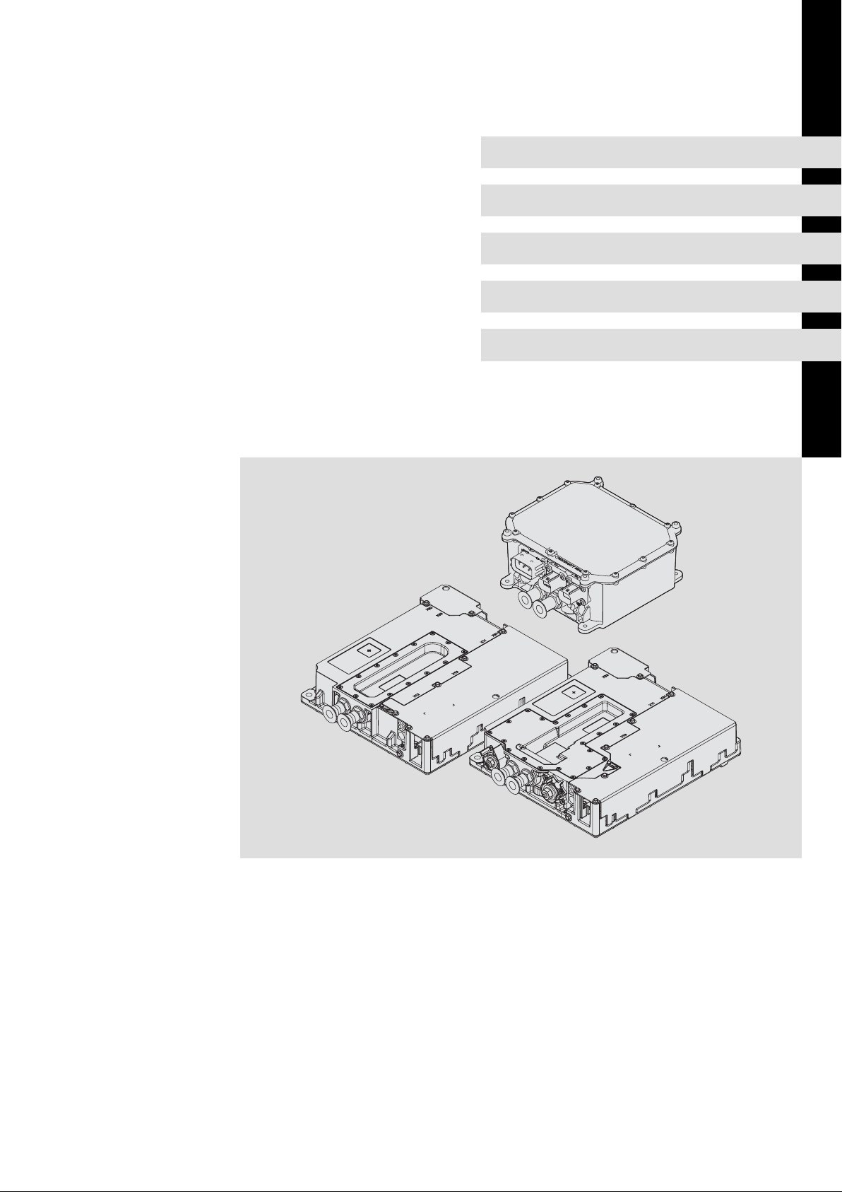
MOBILE DCU
MOBILE PSU
MOBILE DCU PSU
MOBILE DCU S
Ò
Page 2

0Fig. 0Tab. 0
Page 3

Contents i
1 About this documentation 5. . . . . . . . . . . . . . . . . . . . . . . . . . . . . . . . . . . . . . . . . . . . . . . . . .
1.1 Target group 5. . . . . . . . . . . . . . . . . . . . . . . . . . . . . . . . . . . . . . . . . . . . . . . . . . . . . . . .
1.2 Validity information 5. . . . . . . . . . . . . . . . . . . . . . . . . . . . . . . . . . . . . . . . . . . . . . . . . .
1.3 Document history 6. . . . . . . . . . . . . . . . . . . . . . . . . . . . . . . . . . . . . . . . . . . . . . . . . . . .
1.4 Conventions used 6. . . . . . . . . . . . . . . . . . . . . . . . . . . . . . . . . . . . . . . . . . . . . . . . . . . .
1.5 Terms and abbreviations used 7. . . . . . . . . . . . . . . . . . . . . . . . . . . . . . . . . . . . . . . . . .
1.6 Notes used 9. . . . . . . . . . . . . . . . . . . . . . . . . . . . . . . . . . . . . . . . . . . . . . . . . . . . . . . . . .
2 Safety instructions 10. . . . . . . . . . . . . . . . . . . . . . . . . . . . . . . . . . . . . . . . . . . . . . . . . . . . . . . .
2.1 General safety and application notes for Lenze MOBILE devices 10. . . . . . . . . . . . . .
2.2 Residual hazards 13. . . . . . . . . . . . . . . . . . . . . . . . . . . . . . . . . . . . . . . . . . . . . . . . . . . . .
3 Product description 14. . . . . . . . . . . . . . . . . . . . . . . . . . . . . . . . . . . . . . . . . . . . . . . . . . . . . . . .
3.1 System overview 14. . . . . . . . . . . . . . . . . . . . . . . . . . . . . . . . . . . . . . . . . . . . . . . . . . . . .
3.2 Device features 19. . . . . . . . . . . . . . . . . . . . . . . . . . . . . . . . . . . . . . . . . . . . . . . . . . . . . .
3.3 Identification 20. . . . . . . . . . . . . . . . . . . . . . . . . . . . . . . . . . . . . . . . . . . . . . . . . . . . . . . .
3.4 Type code 21. . . . . . . . . . . . . . . . . . . . . . . . . . . . . . . . . . . . . . . . . . . . . . . . . . . . . . . . . .
4 Technical data 22. . . . . . . . . . . . . . . . . . . . . . . . . . . . . . . . . . . . . . . . . . . . . . . . . . . . . . . . . . . .
4.1 General data and operating conditions 22. . . . . . . . . . . . . . . . . . . . . . . . . . . . . . . . .
4.2 Rated data of the devices for HV on−board supply system 800 V 26. . . . . . . . . . . . .
4.2.1 Product finder 26. . . . . . . . . . . . . . . . . . . . . . . . . . . . . . . . . . . . . . . . . . . . . . . .
4.2.2 DC/AC inverter 27. . . . . . . . . . . . . . . . . . . . . . . . . . . . . . . . . . . . . . . . . . . . . .
4.2.3 DC/DC converter 30. . . . . . . . . . . . . . . . . . . . . . . . . . . . . . . . . . . . . . . . . . . .
4.3 Control of MOBILE DCU, PSU, DCU PSU 31. . . . . . . . . . . . . . . . . . . . . . . . . . . . . . . . . . .
4.3.1 Voltage supply 31. . . . . . . . . . . . . . . . . . . . . . . . . . . . . . . . . . . . . . . . . . . . . .
4.3.2 Digital inputs 31. . . . . . . . . . . . . . . . . . . . . . . . . . . . . . . . . . . . . . . . . . . . . . . .
4.3.3 Digital outputs 32. . . . . . . . . . . . . . . . . . . . . . . . . . . . . . . . . . . . . . . . . . . . . . .
4.3.4 Potential−free output 32. . . . . . . . . . . . . . . . . . . . . . . . . . . . . . . . . . . . . . . . . .
4.3.5 CAN bus 33. . . . . . . . . . . . . . . . . . . . . . . . . . . . . . . . . . . . . . . . . . . . . . . . . . . . .
4.4 Control of MOBILE DCU S 34. . . . . . . . . . . . . . . . . . . . . . . . . . . . . . . . . . . . . . . . . . . . . .
4.4.1 Voltage supply 34. . . . . . . . . . . . . . . . . . . . . . . . . . . . . . . . . . . . . . . . . . . . . .
4.4.2 Digital inputs 34. . . . . . . . . . . . . . . . . . . . . . . . . . . . . . . . . . . . . . . . . . . . . . . .
4.4.3 Thermal sensor input 35. . . . . . . . . . . . . . . . . . . . . . . . . . . . . . . . . . . . . . . . .
4.4.4 CAN bus 35. . . . . . . . . . . . . . . . . . . . . . . . . . . . . . . . . . . . . . . . . . . . . . . . . . . . .
4.5 Water cooling 36. . . . . . . . . . . . . . . . . . . . . . . . . . . . . . . . . . . . . . . . . . . . . . . . . . . . . . . .
4.6 Dimensions 38. . . . . . . . . . . . . . . . . . . . . . . . . . . . . . . . . . . . . . . . . . . . . . . . . . . . . . . . .
5 Installation 39. . . . . . . . . . . . . . . . . . . . . . . . . . . . . . . . . . . . . . . . . . . . . . . . . . . . . . . . . . . . . . .
5.1 Important notes 39. . . . . . . . . . . . . . . . . . . . . . . . . . . . . . . . . . . . . . . . . . . . . . . . . . . . .
5.2 Mechanical installation 41. . . . . . . . . . . . . . . . . . . . . . . . . . . . . . . . . . . . . . . . . . . . . . .
EDSMDAG EN 2.0
Ò
3
Page 4

Contentsi
5.3 Water cooling 43. . . . . . . . . . . . . . . . . . . . . . . . . . . . . . . . . . . . . . . . . . . . . . . . . . . . . . . .
5.4 EMC−compliant installation 44. . . . . . . . . . . . . . . . . . . . . . . . . . . . . . . . . . . . . . . . . . . .
5.4.1 Equipotential bonding 44. . . . . . . . . . . . . . . . . . . . . . . . . . . . . . . . . . . . . . . . .
5.4.2 Shielding 45. . . . . . . . . . . . . . . . . . . . . . . . . . . . . . . . . . . . . . . . . . . . . . . . . . .
5.4.3 HV on−board cable 45. . . . . . . . . . . . . . . . . . . . . . . . . . . . . . . . . . . . . . . . . . . .
5.4.4 Motor cable 46. . . . . . . . . . . . . . . . . . . . . . . . . . . . . . . . . . . . . . . . . . . . . . . . . .
5.4.5 Control cables 47. . . . . . . . . . . . . . . . . . . . . . . . . . . . . . . . . . . . . . . . . . . . . . . .
5.4.6 Detecting and eliminating EMC interferences 47. . . . . . . . . . . . . . . . . . . . .
5.5 Electrical installation 48. . . . . . . . . . . . . . . . . . . . . . . . . . . . . . . . . . . . . . . . . . . . . . . . . .
5.5.1 Basic circuit diagrams 48. . . . . . . . . . . . . . . . . . . . . . . . . . . . . . . . . . . . . . . . .
5.5.2 Fuses and cable cross−sections 51. . . . . . . . . . . . . . . . . . . . . . . . . . . . . . . . . .
5.5.3 Wiring the CAN bus 52. . . . . . . . . . . . . . . . . . . . . . . . . . . . . . . . . . . . . . . . . . .
5.6 Connections of MOBILE DCU, PSU, DCU PSU 54. . . . . . . . . . . . . . . . . . . . . . . . . . . . . .
5.6.1 PE conductor 54. . . . . . . . . . . . . . . . . . . . . . . . . . . . . . . . . . . . . . . . . . . . . . . . .
5.6.2 HV on−board supply system 54. . . . . . . . . . . . . . . . . . . . . . . . . . . . . . . . . . . .
5.6.3 Motor 55. . . . . . . . . . . . . . . . . . . . . . . . . . . . . . . . . . . . . . . . . . . . . . . . . . . . . . .
5.6.4 Feedback 56. . . . . . . . . . . . . . . . . . . . . . . . . . . . . . . . . . . . . . . . . . . . . . . . . . . .
5.6.5 LV on−board supply system 57. . . . . . . . . . . . . . . . . . . . . . . . . . . . . . . . . . . . .
5.6.6 Control system 58. . . . . . . . . . . . . . . . . . . . . . . . . . . . . . . . . . . . . . . . . . . . . . .
5.6.7 Addressing CAN bus nodes 59. . . . . . . . . . . . . . . . . . . . . . . . . . . . . . . . . . . . .
5.6.8 Activating the terminating resistor 61. . . . . . . . . . . . . . . . . . . . . . . . . . . . . .
5.7 Connections of MOBILE DCU S 62. . . . . . . . . . . . . . . . . . . . . . . . . . . . . . . . . . . . . . . . . .
5.7.1 PE conductor 62. . . . . . . . . . . . . . . . . . . . . . . . . . . . . . . . . . . . . . . . . . . . . . . . .
5.7.2 HV on−board supply system 62. . . . . . . . . . . . . . . . . . . . . . . . . . . . . . . . . . . .
5.7.3 Motor 63. . . . . . . . . . . . . . . . . . . . . . . . . . . . . . . . . . . . . . . . . . . . . . . . . . . . . . .
5.7.4 Control system 63. . . . . . . . . . . . . . . . . . . . . . . . . . . . . . . . . . . . . . . . . . . . . . .
5.7.5 Addressing CAN bus nodes 64. . . . . . . . . . . . . . . . . . . . . . . . . . . . . . . . . . . . .
5.7.6 Activating the terminating resistor 66. . . . . . . . . . . . . . . . . . . . . . . . . . . . . .
6 Commissioning 67. . . . . . . . . . . . . . . . . . . . . . . . . . . . . . . . . . . . . . . . . . . . . . . . . . . . . . . . . . .
7 Diagnostics 68. . . . . . . . . . . . . . . . . . . . . . . . . . . . . . . . . . . . . . . . . . . . . . . . . . . . . . . . . . . . . . .
7.1 Device status 68. . . . . . . . . . . . . . . . . . . . . . . . . . . . . . . . . . . . . . . . . . . . . . . . . . . . . . . .
7.1.1 MOBILE DCU, PSU, DCU PSU 68. . . . . . . . . . . . . . . . . . . . . . . . . . . . . . . . . . . .
7.1.2 MOBILE DCU S 68. . . . . . . . . . . . . . . . . . . . . . . . . . . . . . . . . . . . . . . . . . . . . . .
8 Accessories (overview) 69. . . . . . . . . . . . . . . . . . . . . . . . . . . . . . . . . . . . . . . . . . . . . . . . . . . . .
8.1 Prefabricated cables and plug accessories 70. . . . . . . . . . . . . . . . . . . . . . . . . . . . . . . .
8.1.1 MOBILE DCU, PSU, DCU PSU 70. . . . . . . . . . . . . . . . . . . . . . . . . . . . . . . . . . . .
8.2 Individual parts for the electrical installation 71. . . . . . . . . . . . . . . . . . . . . . . . . . . . .
8.2.1 MOBILE DCU, PSU, DCU PSU 71. . . . . . . . . . . . . . . . . . . . . . . . . . . . . . . . . . . .
8.2.2 MOBILE DCU S 72. . . . . . . . . . . . . . . . . . . . . . . . . . . . . . . . . . . . . . . . . . . . . . .
9 Index 74. . . . . . . . . . . . . . . . . . . . . . . . . . . . . . . . . . . . . . . . . . . . . . . . . . . . . . . . . . . . . . . . . . . .
4
Ò
EDSMDAG EN 2.0
Page 5

1 About this documentation
This manual contains the complete information on the intended use of components of the
MOBILE product platform in mobile applications in or on vehicles.
I Tip!
Information and tools concerning the Lenze products can be found in the
download area at
www.lenze.com
1.1 Target group
This manual is intended for all persons who dimension, install, commission and adjust
drives with the MOBILE product platform.
About this documentation
Target group
1
1.2 Validity information
This manual is valid for the components with the type designation:
Device type Type designation from SW
MOBILE Advanced DCU EMDAG2xxxxxxxxxx1x 06.0
MOBILE Advanced PSU EMDAG3xxxxxxxxxx1x 06.0
MOBILE Advanced DCU PSU EMDAG4xxxxxxxxxx1x 06.0
MOBILE DCU S EMDAG5xxxxxxxxxx0x 06.0
Accessories EMDAZ... ˘
The breakdown of the type designation can be found in the "Product description" chapter.
(¶ 21)
EDSMDAG EN 2.0
Ò
5
Page 6
1
About this documentation
Document history
1.3 Document history
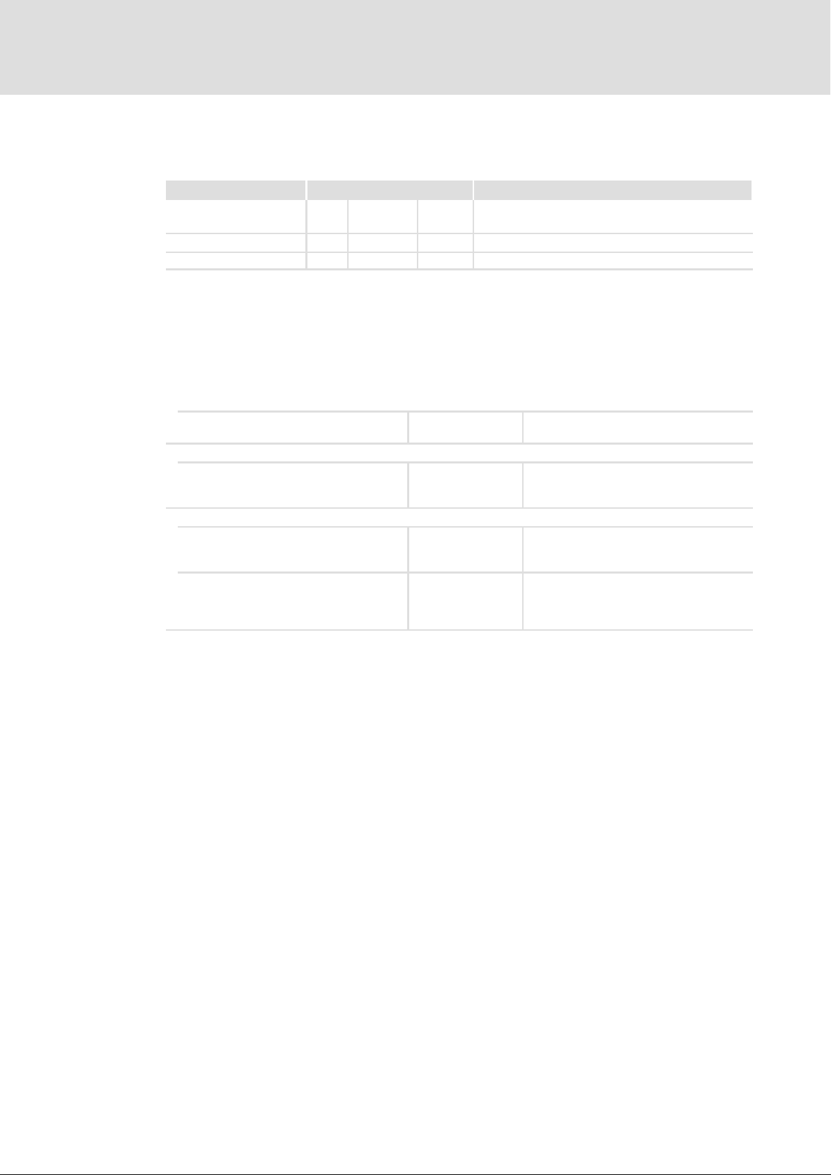
Material number Version Description
.Rtù 2.0 04/2018 TD29 Revision of the Hardware Manual to the hardware
13473426 1.1 10/2014 TD15 Corrections
13473426 1.0 10/2014 TD15 First edition
1.4 Conventions used
This documentation uses the following conventions to distinguish between different
types of information:
Spelling of numbers
Decimal separator
Tex t
Program name » « PC software
Icons
Page reference ^ Reference to another page with additional
Documentation reference , Reference to another documentation with
version x1x
Point In general, the decimal point is used.
For instance: 1234.56
For example: »Engineer«, »Global Drive
Control« (GDC)
information
For instance: ^ 16 = see page 16
additional information
For example: , EDKxxx = see
documentation EDKxxx
6
Ò
EDSMDAG EN 2.0
Page 7

1.5 Terms and abbreviations used
Term Description
AppC Application Controller
CAN Controller Area Network or electric circuit for CAN with its own current
DC Direct current
DCU DC/AC inverter
DCU PSU Combined device
Double inverter Inverter for two motors or two drives
Single inverter Inverter for one motor or one drive
HCU Host Control Unit (also Vehicle Control Unit or Machine Control Unit)
HV on−board supply system High−voltage (on−board) system ISO 6469−3, voltage class B
IT Isolé Terre system (star point not earthed)
TRM15 Terminal 15: Terminal 15 is the original contact "Ignition on" at the
TRM30 Positive voltage of the voltage supply (12 V or 24 V)
TRM31 Negative voltage of the voltage supply (0 V). This signal is potentially
Performance electronics Rectification, DC bus and DC−AC converter
LV on−board supply system Low−voltage (on−board) system ISO 6469−3, voltage class A
About this documentation
Terms and abbreviations used
supply
Drive Control Unit
steering lock which switches on the MOBILE PSU/DCU by a switch−on
pulse (LOW−HIGH edge).
connected to the vehicle chassis.
1
MC Motor Controller
MOBILE Product platform for automotive drive solutions
»MOBILE Engineer« Engineering tool, software solution for easy engineering in all phases
Module Electronic unit or device
Motor A First motor controlled by MC
Motor B Second motor controlled by MC (optional)
n. c. Not connected
PE Chassis
Protective earth
Private CAN Real time CAN Bus which is used for controlling drives.
PSU DC/DC converter
Power Supply Unit
Public CAN CAN bus on the vehicle side which is used for integrating the MOBILE
Control electronics Open−loop control, closed−loop control, setpoint generation, monitoring
SM Synchronous motor
Tn Terre Neutre system (star point is earthed)
DC bus DC bus
SLVCI Sensorless vector control for asynchronous motors
SLVCS Sensorless vector control for synchronous motors
SLVFCI Sensorless V/f characteristic control for asynchronous motors
Ctrl Control
VCI Vector control for asynchronous motors
VCS Vector control for synchronous motors
PSU/DCU into vehicles.
EDSMDAG EN 2.0
Ò
7
Page 8

1
About this documentation
Terms and abbreviations used
DescriptionTerm
DC−bus level Energy storage between rectification and DCAC conversion, for one or
DC−bus connection, DC−bus
operation
more controllers
Interconnection of several inverters on the DC−bus level
8
Ò
EDSMDAG EN 2.0
Page 9

1.6 Notes used
The following pictographs and signal words are used in this documentation to indicate
dangers and important information:
Safety instructions
Structure of safety instructions:
} Danger!
(characterises the type and severity of danger)
Note
(describes the danger and gives information about how to prevent dangerous
situations)
Pictograph and signal word Meaning
{ Danger!
} Danger!
( Stop!
About this documentation
Notes used
Danger of personal injury through dangerous electrical voltage.
Reference to an imminent danger that may result in death or
serious personal injury if the corresponding measures are not
taken.
Danger of personal injury through a general source of danger.
Reference to an imminent danger that may result in death or
serious personal injury if the corresponding measures are not
taken.
Danger of property damage.
Reference to a possible danger that may result in property
damage if the corresponding measures are not taken.
1
Application notes
Pictograph and signal word Meaning
) Note!
I Tip!
,
Important note to ensure troublefree operation
Useful tip for simple handling
Reference to another documentation
EDSMDAG EN 2.0
Ò
9
Page 10

2
Safety instructions
General safety and application notes for Lenze MOBILE devices
2 Safety instructions
2.1 General safety and application notes for Lenze MOBILE devices
Observe the following basic safety instructions when using the MOBILE inverters (devices).
A non−compliance may cause severe injury to persons and/or damage to material assets.
General
ƒ For devices with ECE R10 approval, the ECE regulation no. 100 has to be observed.
For your personal safety
ƒ Only use the devices as directed.
ƒ Never commission the devices in the event of visible damage.
ƒ Never commission the devices before they have been completely mounted.
ƒ Only separate or plug connectors if the high−voltage mains is switched off and
discharged:
– Power connector (marked with a warning sign on the cover)
– Signal connector
ƒ Do not open the housings of the devices.
ƒ Do not carry out any technical changes on the devices.
ƒ Only use the accessories approved for the devices.
ƒ Only use original spare parts from Lenze.
ƒ Observe all regulations for the prevention of accidents, directives and laws
applicable on the site of installation.
ƒ Transport, installation, commissioning and maintenance work must only be carried
out by qualified personnel.
– Observe IEC 364 and CENELEC HD 384 or DIN VDE 0100 and IEC report 664 or DIN
VDE 0110 and all national regulations for the prevention of accidents.
– According to this basic safety information, qualified, skilled personnel are persons
who are familiar with the assembly, installation, commissioning, and operation of
the product and who have the qualifications necessary for their occupation.
ƒ Observe all specifications in the documentation.
– Carry out installation and operation in accordance with the documentation.
– This is the condition for safe and trouble−free operation and the achievement of
the specified product features.
– The procedural notes and circuit details described in the documentation are only
proposals. It is up to the user to check whether they can be transferred to the
particular applications. Lenze Schmidhauser does not accept any liability for the
suitability of the procedures and circuit proposals described.
10
Ò
EDSMDAG EN 2.0
Page 11

Safety instructions
General safety and application notes for Lenze MOBILE devices
ƒ The devices and related components can − depending on the degree of protection −
have live, movable or rotating parts during operation.
– Surfaces can be hot.
– Do not remove required covers.
– Do not touch exposed contacts or non−insulated cable ends.
– For more information, please see the documentation.
ƒ Before touching conductive components, ensure isolation from supply by means of
measurement.
The device−specific safety and application notes given in the chapter "Residual hazards"
of this documentation must be observed.
Application as directed
The devices meet the requirements of the Low−Voltage Directive 2006/95/EC. The
harmonised standard EN 61800−5−1 applies to the devices.
The devices marked with E1 are components which are designed for installation in vehicles
(ECE approval). They are not to be used as domestic appliances, but only for industrial
purposes according to EN 61000−3−2.
The technical data and supply conditions can be obtained from the nameplate and the
documentation. They must be strictly observed.
Commissioning (i.e. start of the operation as intended) of devices installed in vehicles is
only permissible if the following has been verified:
2
ƒ The vehicle corresponds to the valid vehicle standards (e.g. ECE R100, safety
requirements with respect to the electric power train of road vehicles); EN 60204 is
observed.
ƒ The EMC Directive 2004/104/EC (last supplemented by 2009/19/EC) is complied
with.
Transport, storage
Please observe the notes on transport, storage, and appropriate handling.
Observe the climatic conditions according to the technical data.
Installation
You have to mount, connect and cool the devices according to the specifications of the
respective documentation. The equipotential bonding has to be dimensioned sufficiently
and protected against corrosion.
When plug connections are open, the degree of pollution 2 must not be exceeded
according to EN 61800−5−1.
Ensure proper handling and avoid excessive mechanical stress.
Do not touch any electronic components and contacts. The devices contain electrostatic
sensitive devices that can be damaged easily by improper handling. Damaged devices
must not be commissioned.
EDSMDAG EN 2.0
Ò
11
Page 12

2
Safety instructions
General safety and application notes for Lenze MOBILE devices
Electrical connection
When working on live devices, observe the applicable national regulations for the
prevention of accidents and technical measures for occupational safety and health.
The electrical installation must be carried out according to the appropriate regulations
(e.g. cable cross−sections, fuses, PE connection). Additional information can be obtained
from the documentation.
The documentation contains notes concerning wiring according to EMC regulations
(shielding, earthing, filters and cable routing). The compliance with limit values required
by the EMC legislation is the responsibility of the manufacturer of vehicles or systems or
machines.
Operation
If necessary, systems including these devices must be equipped with additional
monitoring and protection devices according to the valid safety regulations (e.g. law on
technical equipment, regulations for the prevention of accidents). The devices can be
adapted to your application by parameter settings. Please observe the corresponding
information given in the documentation.
After the devices have been disconnected from the supply voltage, all live components and
connectors must not be touched immediately because capacitors can still be charged.
Please observe the corresponding stickers on the devices.
Ensure that all protection covers are closed and screwed during operation.
Maintenance and servicing
The devices do not require any maintenance if the prescribed operating conditions are
observed.
The external cleaning of the devices has to be made in the course of the general care of the
vehicles, machines, or systems. Depending on the mounting place and the possible
pollution, the cover sensor has to be cleaned regularly.
Disposal
For a professional disposal and utilisation of the devices, please comply with the valid
regulations, e.g. 2000/53/EC (last amended by 2011/37/EC).
12
Ò
EDSMDAG EN 2.0
Page 13
Safety instructions
Residual hazards
2
2.2 Residual hazards
Protection of persons
ƒ Switch off the high voltage on−board voltage completely before working on the
devices.
ƒ Before working on the device, check whether all power terminals are deenergised
because
– after disconnection, the power terminals U, V and W remain live for at least 5
minutes depending on the system.
– the power terminals +UG, −UG, U, V and W remain live while the motor is rotating.
– Batteries and energy storages can carry hazardous voltage over a longer period of
time.
Device protection
ƒ Connect/disconnect all pluggable terminals only in deenergised condition!
ƒ Detach the controllers from the installation, e.g. from the motor or mounting wall,
only in deenergised condition!
Motor protection
ƒ With some settings of the controller, the connected motor can be overheated.
– E.g. longer operation of the DC injection brake.
– Longer operation of self−ventilated motors at low speed.
– Wrong frequency or voltage settings in the motor parameters (especially with
120 Hz motors).
Protection of the machine/system
ƒ Drives can reach dangerous overspeeds (e.g. setting of high output frequencies in
connection with motors and machines unsuitable for such conditions):
– The controllers do not offer any protection against such operating conditions. Use
additional components for this purpose.
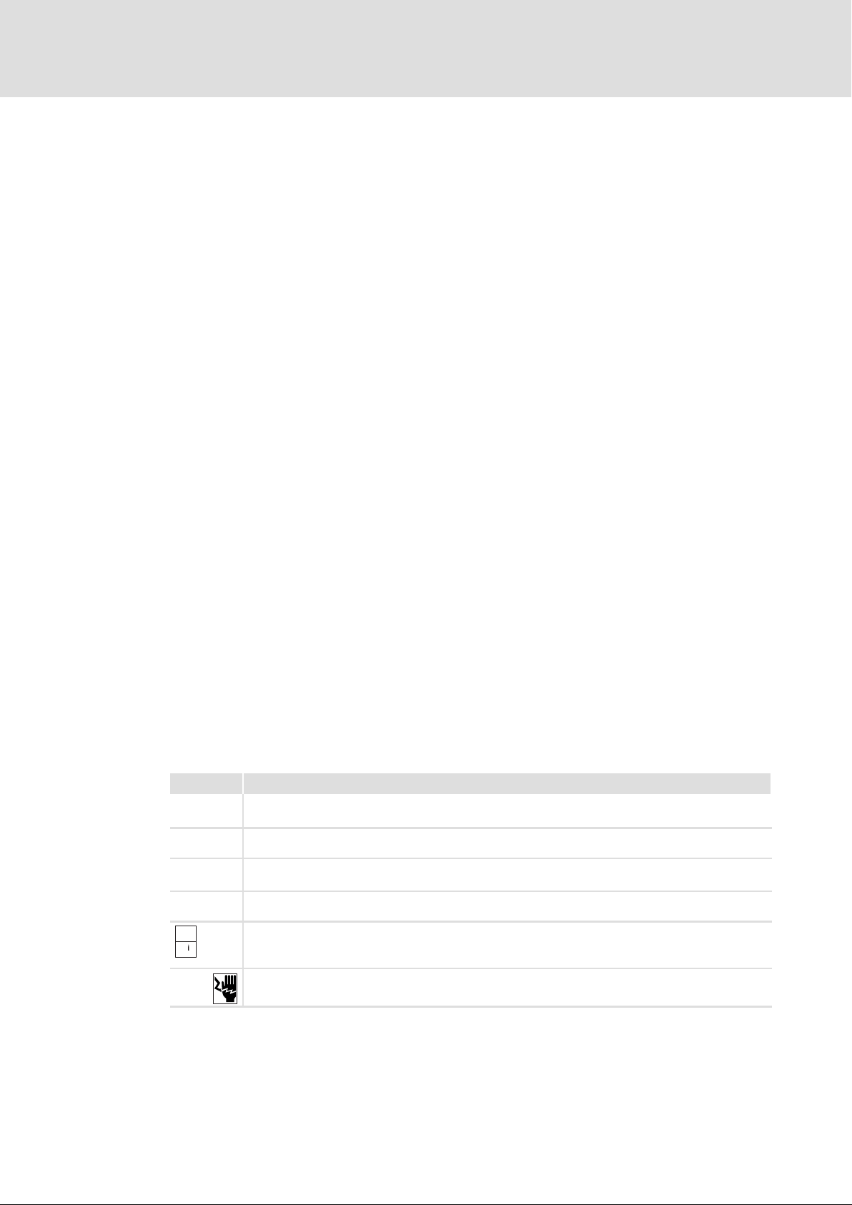
Symbol Description
Þ
}
'
|
}
¶
{
Long discharge time: All power terminals remain live for a few minutes after mains disconnection!
The duration is given under the warning symbol on the device.
High leakage current: Carry out fixed installation and PE connection according to EN 6180051!
Electrostatic sensitive devices: Before working on the device, the personnel must be free of
electrostatic charge!
Hot surface: Risk of burns! Hot surfaces should not be touched without wearing protective gloves.
Read the documentation: Before working on the device, the personnel must read and act in
accordance with the documentation supplied with the product, especially the warnings and the
safety instructions!
Dangerous voltage: Before working on the device, switch off the HV on−board voltage completely!
EDSMDAG EN 2.0
Ò
13
Page 14
3
Product description
System overview
3 Product description
3.1 System overview
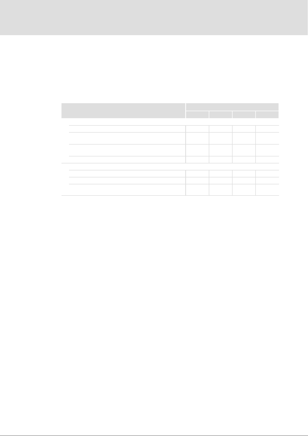
The components from the MOBILE modular system are used to realise auxiliary unit
applications in commercial vehicles by means of electric motors:
Device type
Double inverter for two motors l ˘ ˘ ˘
DC/DC converter (converter HV on−board supply system/LV
on−board supply system)
Combination of single inverter for one motor and DC/DC
converter
Single inverter for one motor ˘ ˘ ˘ l
Application
Simple drives of pumps and fans l ˘ l l
Controlled and positioning drives l l l
Charging the LV on−board supply system with regenerative
energy of drives
MOBILE
DCU PSU DCU PSU DCU S
˘ l l ˘
˘ ˘ l ˘
˘ l l ˘
14
Ò
EDSMDAG EN 2.0
Page 15
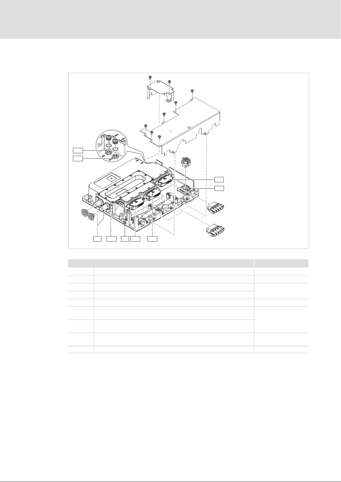
MOBILE DCU
X33
X32
Product description
System overview
X11
X31
3
LED
+
XX
X12
X13
2×
^ 55
^ 56
^ 54
A
XX
Fig. 1 MOBILE DCU (EMDxG2...)
Connections and elements Info
0 Connection of water cooling ^ 43
X11 Connection of HV system 800 V DC ^ 54
X12 Connection of motor A
X13 Connection of motor B
X31 Vehicle interface, connection of control voltage, control signals, CAN ^ 58
X32 Connection of resolver and temperature monitoring of motor A
(by default sealed with plug)
X33 Connection of resolver and temperature monitoring of motor B
(by default sealed with plug)
+ PE connection ^ 44
LED LED status display ^ 68
EMDAG013a
EDSMDAG EN 2.0
Ò
15
Page 16
3
Product description
System overview
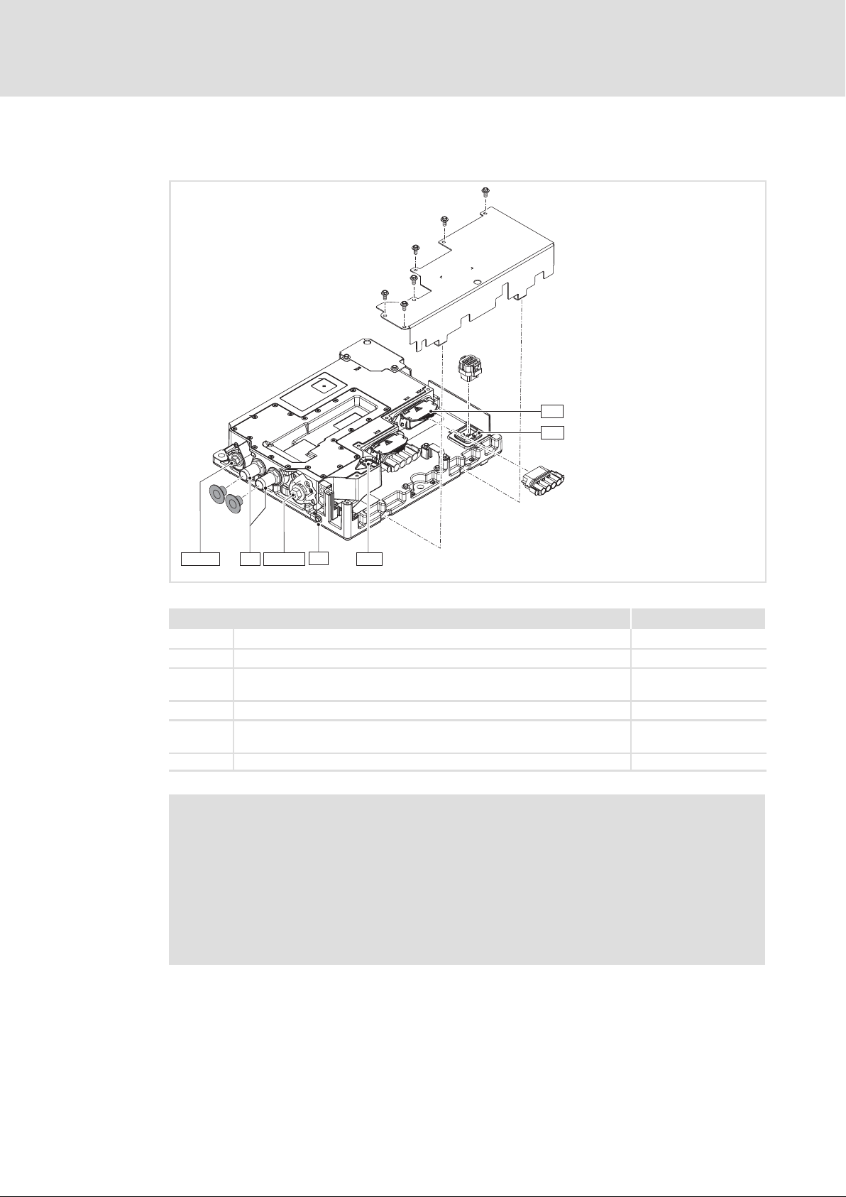
MOBILE PSU
X11
X31
+
X21/B-
Fig. 2 MOBILE PSU (EMDxG3...)
Connections and elements Info
0 Connection of water cooling ^ 43
X11 Connection of HV system 400 VDC or 800 VDC ^ 54
X21/B+
X21/B−
X31 Vehicle interface, connection of control voltage, control signals, CAN ^ 58
+ PE connection ^ 44
LED LED status display ^ 68
X21/B+
XX
A LED
LV mains 14 VDC or 28 VDC
Connection of the on−board battery
XX
^ 57
^ 54
{ Danger!
Dangerous electrical voltage
The terminal X13 carries electrical voltage.
Possible consequences:
ƒ Death or severe injury if the power terminals are touched.
Protective measures:
ƒ Do not remove the blanking plug from X13.
EMDAG012a
16
Ò
EDSMDAG EN 2.0
Page 17
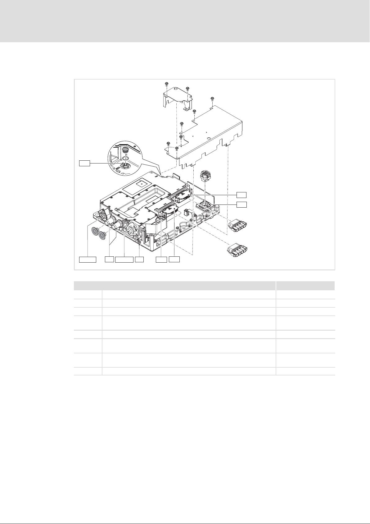
MOBILE DCU PSU
X33
Product description
System overview
X11
X31
3
XX
X21/B-
Fig. 3 MOBILE DCU/PSU (EMDxG4...)
Connections and elements Info
0 Connection of water cooling ^ 43
X11 Connection of HV system 400 VDC or 800 VDC ^ 54
X13 Motor connection ^ 55
X21/B+
X21/B−
X31 Vehicle interface, connection of control voltage, control signals, CAN ^ 58
X33 Connection of resolver and motor temperature monitoring
+ PE connection ^ 44
LED LED status display ^ 68
A
X21/B+
LV mains 14 VDC or 28 VDC
Connection of the on−board battery
(by default sealed with plug)
+
XX
LED
X13
^ 57
^ 56
^ 54
EMDAG011a
EDSMDAG EN 2.0
Ò
17
Page 18
3
Product description
System overview
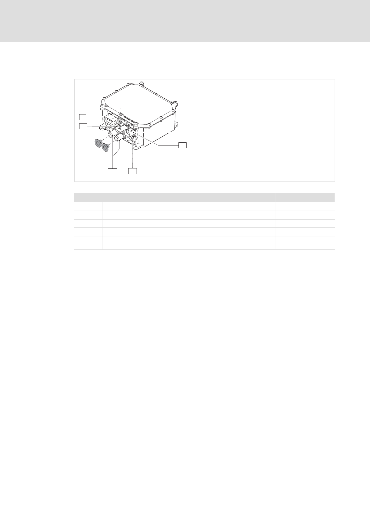
MOBILE DCU S
X1
X2
X3
+
XX
Fig. 4 MOBILE DCU S (EMDxG5...)
Connections and elements Info
0 Connection of water cooling ^ 43
X1 Vehicle interface, connection of control voltage, control signals, CAN ^ 63
X2 Connection of HV on−board supply system 800 V DC ^ 62
X3 Motor connection ^ 63
+ PE connection ^ 62
XX
A
EMDAG028b
^ 44
18
Ò
EDSMDAG EN 2.0
Page 19

3.2 Device features
Device feature EMDAG2... EMDAG3... EMDAG4... EMDAG5...
Power range
(Peak Power)
DC/AC inverter 2 ˘ 1 1
DC/DC converter ˘ 1 1 ˘
Approval acc. to ECE R10 l l l l
Degree of protection IP6K9K IP6K9K IP6K9K IP6K9K
Cooling Water / glycol (^ 36)
Mounting type free
12/24−V voltage for maintaining the
control functionality in the case of
mains failure
Digital inputs 4 4 4 4
configurable as analog input 2 2 2 2
configurable as frequency input 2 2 2 ˘
Digital outputs 4 4 4 ˘
Resolver connection 2 ˘ 1 ˘
Motor temperature monitoring PT1000, KTY83/110, KTY84/130, thermostat (normally−closed contact)
Public CAN l l l l
Baud rate kbps 125 ... 500 125 ... 500 125 ... 500 125 ... 500
Private CAN l l l l
Baud rate kbps 125 ... 1000 125 ... 1000 125 ... 1000 125 ... 500
Operation in generator mode
(optional)
Loop−through of HV system l l l ˘
Overload cycle at 1.8 × I
Overload cycle at 1.5 × I
Motor speed range rpm −32000 ... 32255 ˘ −32000 ... 32255 −32000 ... 32255
Technology application
Actuator speed l ˘ l l
Switch−off positioning m ˘ m ˘
Absolute positioning m ˘ m ˘
rated
rated
Product description
Device features
kW 7.5 ... 60 2.8 ... 5.6 2.8 ... 60 7.5 ... 22
l l l l
acc. to DIN44080, PTC acc. to DIN44081
l ˘ l l
10 s ˘ 10 s 10 s
60 s ˘ 60 s 60 s
3
EDSMDAG EN 2.0
l Included as standard
m Optionally available
˘ Not available
Ò
19
Page 20
3
Product description
Identification
3.3 Identification
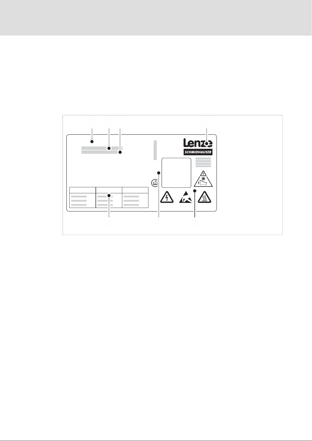
Each device is marked with a clear nameplate. The following data on the nameplate serves
to identify each device:
ƒ Type designation (product key)
ƒ Technical data
ƒ Serial number (SN)
MOBILE
Type:
SN:
ÄIDNummer123456789ä
-ECER10-
Xxx Xxx Xxx
Fig. 5 Nameplate
Product name
Type designation
Serial number
Manufacturer
Warning symbol: discharge time, dangerous electrical voltage, ESD, hot surface
Approval identification
Technical data
EMDAG051
Note
Via the type designation, detailed device properties can be identified using the following
type code. The list containing the type code, features, and device properties does not take
any restrictions with regard to possible combinations into consideration.
20
Ò
EDSMDAG EN 2.0
Page 21

3.4 Type code
Device version
A = Advanced
Device type
1 = DCU: single inverter
2 = DCU: double inverter
3 = PSU: DC/DC converter
4 = DCU PSU: single inverter,
5 = DCU S: single inverter
DCU: peak output power at X12
DCU PSU: output power at X21
PSU: output power at X21
DCU S: peak output power at X3
Example:
603 = 60 × 10
562 = 56 × 10
DC/DC converter
3
W = 60 kW
2
W = 5.6 kW
Product description
Type code
Position 1 ... 5 6 7, 8, 9 10, 11, 12 13 14 15 16, 17, 18
EMDxG X xxx xxx x x x xxx
3
DCU: peak output power at X13
DCU PSU: peak output power at X13
Example:
303 = 30 × 10
PSU: 000
DCU S: 000
Voltage range LV system / HV system
U = 14 or 28 V / 800 V
V = 14 or 28 V / 400 V
P = 14 V / 400 V
T = 14V / 800 V
S = 28 V / 400 V
C = 28 V / 800 V
Communication
N = not relevant
0 = CANopen (Private CAN), J1939 (Public CAN)
Special version
0 = standard
Hardware version
x0x = 1st version
x1x = 2nd version
3
W = 30 kW
EDSMDAG EN 2.0
Ò
21
Page 22
4
Technical data
General data and operating conditions
4 Technical data
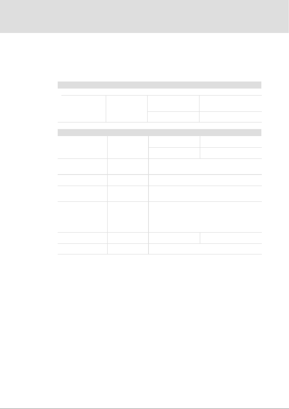
4.1 General data and operating conditions
Conformity and approval
Approval
ECE
Protection of persons and equipment
Degree of protection ISO 20653
Insulation test EN 61800−5−1 Final test with 2.6kVDC between HV on−board supply
Insulation of control
circuits
Short−circuit strength Motor connection: limited short−circuit strength, the inverter
Protective measures
against
Leakage current EN 61800−5−1 IAC>3.5 mA
On/off switching MOBILE devices are suitable for frequent on/off switching,
R10 Rev. 5
EN 61800−5−1
IEC 60664−1
ß 10R − 05 7105
(see nameplate)
ß 10R − 05 8467
(see nameplate)
IP 6K9K
IP 6K7
system/LV on−board supply system and HV on−board supply
system/PE
Safe isolation by double/reinforced insulation to the HV
on−board supply system
is disabled, error acknowledgement is required
Control terminals: full short−circuit strength
l Short circuit
l Overvoltage
l Motor Connection Test
l Device overtemperature
l Motor overtemperature
(PTC or thermal contact, I
>10 mA
I
DC
e.g. in the setting−up operation.
MOBILE DCU
MOBILE PSU
MOBILE DCU PSU
MOBILE DCU S
l Plug mounted
l Cover sheet mounted
l Plug mounted
l Without cover sheet
2
t monitoring)
Observe regulations and safety
instructions!
22
Ò
EDSMDAG EN 2.0
Page 23

Technical data
General data and operating conditions
Ambient conditions
Climate
Storage IEC/EN 60721−3−1 1K3 (−25 ... +60 °C)
Transport IEC/EN 60721−3−2 2K4 (−40 ... +85 °C)
Operation
Inverter, DC/DC
converter
Coolant +30 ... +65 °C Coolant pump switches on at a
Service life 50000h at a coolant temperature of
Humidity, relative 5 ... 100 %
Altitude
MOBILE DCU
MOBILE PSU
MOBILE DCUPSU
MOBILE DCU S EN 61800−5−1
Pollution EN 61800−5−1
Vibration resistance (9.81 m/s
Transport
Operation
EN 61800−5−1
2
= 1 g)
ISO 16750−3, code L
−40 ... +85 °C
coolant temperature of +30 °C
55°C
0 ... 2000 m amsl Overvoltage categoryII
2000 ... 4000m amsl Overvoltage categoryI
0 ... 3000 m amsl Overvoltage categoryII
3000 ... 4000 m amsl Overvoltage categoryI
Degree of pollution 4 all plugs closed
Degree of pollution 2 Plugs opened
vertical, tested with 57.9 m/s
horizontal, tested with 57.9 m/s
mechanical shock, tested with 500 m/s2 for 6 ms
2
2
4
Mounting conditions
Mounting place in commercial vehicles (spring−loaded masses)
Mounting position All positions are permissible
Mounting clearances
In the connection area
More pages
Supply conditions
HV on−board supply
system
DC−bus operation l Permissible
Power systems
IT Standard
TT, TN On request
Motors Only use motors that are suitable for operation on the
³ 150 mm
Observe bend radii for cables and hoses.
No special requirements
Direct connection to the HV on−board supply system
When switching elements are used in the HV on−board
supply system, the DC−bus capacitors must be precharged.
l Observe maximum contact load.
l Only use devices with the same voltage range.
inverter.
EDSMDAG EN 2.0
Ò
23
Page 24
4
Technical data
General data and operating conditions
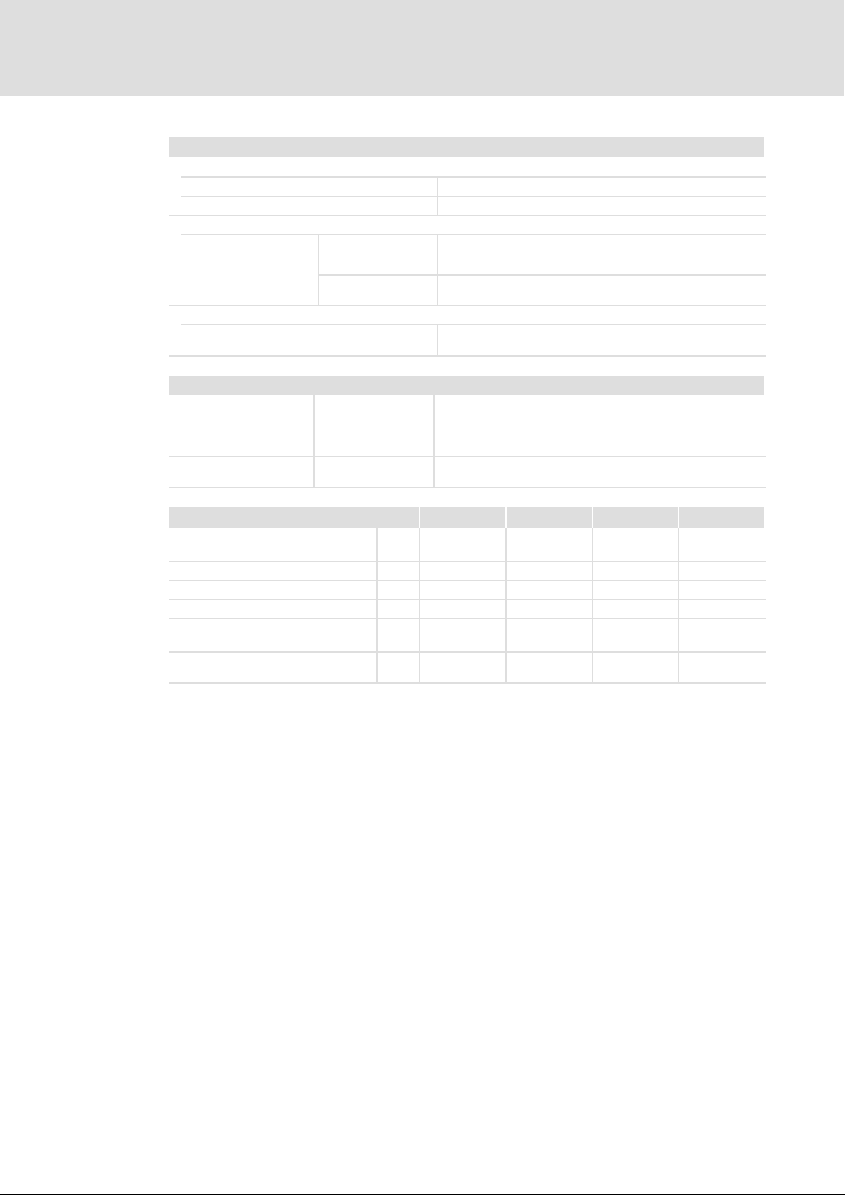
Requirements related to cables for HV on−board supply system and motor
Capacitance per unit length
£2.5 mm2/AWG 14 C
³4 mm2/AWG 12 C
Electric strength
VDE 0250−1 V0/V = 0.6/1.0 kV
UL V³600 V
Cable type
Recommendation l RADOX® cable 155S
EMC
Interference emission ECE R10, Rev. 5 l radiated broad and narrow−band electromagnetic
Immunity to interference ECE R10, Rev. 5 l Immunity to radiated electromagnetic fields
(V0 = r.m.s. value external conductor to PE,
V = r.m.s. value external conductor/external conductor)
(V = r.m.s. value external conductor/external conductor)
l Huber & Suhner
l cable−guided transient noise emissions on the supply
l Immunity to injected interferences on the supply cables
/C
core−core
core−core
interferences
cables
core−shie ld
/C
core−shie ld
<75/150 pF/m
<150/300 pF/m
DC bus EMDAG2... EMDAG3... EMDAG4... EMDAG5...
Rated voltage − HV on−board supply
system
DC−bus capacity mF 240 120 120 80
Discharge resistance kW 300 300 300 573
Capacity against PE nF 9.4 18.8 18.8 9.4
Max. discharge time
(acc. to EN61800−5−1)
Insulation resistance − DC bus/LV
on−board supply system
V DC
s 300 300 300 180
MW 10 10 10 >25
800 800 800 800
24
Ò
EDSMDAG EN 2.0
Page 25

General data and operating conditions
Open and closed loop control
Open and closed loop control processes
Sensorless V/f characteristic control for asynchronous motors (SLVFCI)
l Operation with linear load torque characteristic
l Operation with square−law load torque characteristic
l Operation of socket applications with V/I characteristic
Sensorless vector control for asynchronous motors (SLVCI)
l Dynamic control in all quadrants
Vector control for synchronous motors (VCS)
l Dynamic control in all quadrants
Switching frequency
4 kHz, 8 kHz, 16 kHz,
Either fixed or variable
Output frequency
Range −599 Hz ... +599 Hz
Absolute resolution 0.00024 Hz
Digital setpoint selection
Accuracy Speed 0.00006 rpm
Absolute torque 0.00024 Nm
Standard torque 0.1 %
Voltage (PSU) 0.00195 V
Current (PSU) 0.015625 A
Technical data
4
EDSMDAG EN 2.0
Ò
25
Page 26

4
Technical data
Rated data of the devices for HV on−board supply system 800 V
Product finder
4.2 Rated data of the devices for HV on−board supply system 800 V
4.2.1 Product finder
How to find the data for the desired MOBILE device:
Device Type DC/AC inverter DC/DC converter
X12 X13 X21
MOBILE DCU
MOBILE PSU
MOBILE DCU PSU
MOBILE DCU S
How to find the data: ^ 27 ^ 30
EMDAG2603603U 60 kW 60 kW ˘
EMDAG2303303U 30 kW 30 kW ˘
EMDAG2303153U 30 kW 15 kW ˘
EMDAG2153752U 15 kW 7.5 kW ˘
EMDAG3562000C ˘ ˘ 5.6 kW, 24 V
EMDAG3282000T ˘ ˘ 2.8 kW, 12 V
EMDAG4562603C ˘ 60 kW 5.6 kW, 24 V
EMDAG4282603C ˘ 60 kW 2.8 kW, 24 V
EMDAG4562303C ˘ 30 kW 5.6 kW, 24 V
EMDAG4282303T ˘ 30 kW 2.8 kW, 12 V
EMDAG4562153C ˘ 15 kW 5.6 kW, 24 V
EMDAG4282153T ˘ 15 kW 2.8 kW, 12 V
X3
EMDAG5223000U 22 kW ˘ ˘
EMDAG5153000U 15 kW ˘ ˘
EMDAG5113000U 11 kW ˘ ˘
EMDAG5752000U 7.5 kW ˘ ˘
26
Ò
EDSMDAG EN 2.0
Page 27
Technical data
Rated data of the devices for HV on−board supply system 800 V
DC/AC inverter
4
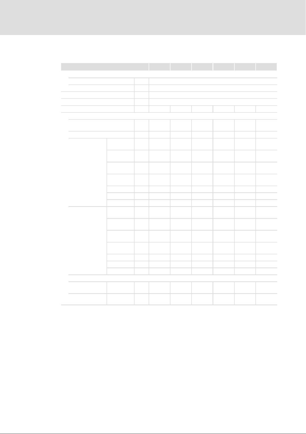
4.2.2 DC/AC inverter
DC/AC inverter 7.5 kW 11 kW 15 kW 22 kW 30 kW 60 kW
Input voltage − HV on−board supply system
Rated voltage V DC 800
Voltage range V DC 100...848
Output voltage 3 AC 0V...510V
Output frequency f
Switch−off at short−circuit current A 24 36.1 48.1 72.1 96.2 192.3
Continuous operation
Current consumption − HV
on−board supply system
Output power kW 5 7.3 10 14.7 20 40
Output current at
<5Hz
f
out
Output current at
>5Hz
f
out
Output current for "socket" application (VAC)
f
<10Hz, VAC 16 kHz,
out
f
>10Hz, VAC 16 kHz,
out
out
2 kHz,
permanent
4 kHz,
permanent
8 kHz,
permanent
16 kHz,
permanent
4 kHz auto A 8 11 15 21.5 32 58
8 kHz auto A 7.2 9.9 13.5 19.4 28.8 52.2
16 kHz auto A 4.4 6.1 8.3 11.8 17.6 31.9
2 kHz,
permanent
4 kHz,
permanent
8 kHz,
permanent
16 kHz,
permanent
4 kHz auto A 10 13.8 18.8 26.9 40 72.5
8 kHz auto A 8 11 15 21.5 32 58
16 kHz auto A 4.8 6.6 9 12.9 19.2 34.8
permanent
permanent
Hz −599...+599
A 9.8 13.5 18.4 26.3 39.2 71
A 8 11 15 21.5 32 58
A 6.4 8.8 12 17.2 25.6 46.4
A 4.8 6.6 9 12.9 19.2 34.8
A 2.4 3.3 4.5 6.5 9.6 17.4
A 12.8 17.6 24 34.4 51.2 92.8
A 10 13.8 18.8 26.9 40 72.5
A 7.2 9.9 13.5 19.4 28.8 52.2
A 4 5.5 7.5 10.8 16 29
A 2.8 3.9 5.3 7.5 10.6 18.6
A 5 6.9 9.5 13.5 18.9 34.2
EDSMDAG EN 2.0
Ò
27
Page 28
4
Technical data
Rated data of the devices for HV on−board supply system 800 V
DC/AC inverter
60 kW30 kW22 kW15 kW11 kW7.5 kWDC/AC inverter
Overcurrent cycle 60s
Operation for 60s with up to 150% of the continuous output current if afterwards a recovery time of 120s with
max. 50% of the continuous output current is observed.
Current consumption − HV
on−board supply system
Max. output power kW 7.5 11 15 22 30 60
Max. output
current at
f
<5Hz
out
Max. output
current at
f
>5Hz
out
Max. output current for "socket" application (VAC)
f
<10Hz, VAC 16 kHz,
out
f
>10Hz, VAC 16 kHz,
out
2 kHz,
permanent
4 kHz,
permanent
8 kHz,
permanent
16 kHz,
permanent
4 kHz auto A 12 16.5 22.5 32.3 48 87
8 kHz auto A 10.4 14.3 19.5 28 41.6 75.4
16 kHz auto A 8 11 15 21.5 32 58
2 kHz,
permanent
4 kHz,
permanent
8 kHz,
permanent
16 kHz,
permanent
4 kHz auto A 14.8 20.4 27.8 39.8 59.2 107.3
8 kHz auto A 12 16.5 22.5 32.3 48 87
16 kHz auto A 8 11 15 21.5 32 58
permanent
permanent
A 14.7 20.2 27.6 39.5 58.8 106.6
A 12 16.5 22.5 32.3 48 87
A 9.2 12.7 17.3 24.7 36.8 66.7
A 5.6 7.7 10.5 15.1 22.4 40.6
A 3.2 4.4 6 8.6 12.8 23.2
A 16 22 30 43 64 116
A 12 16.5 22.5 32.3 48 87
A 8.8 12.1 16.5 23.7 35.2 63.8
A 5.2 7.2 9.8 14 20.8 37.7
A 3.4 4.6 6.3 9.0 12.8 22
A 6.1 8.4 11.4 16.3 22.7 41.2
28
Ò
EDSMDAG EN 2.0
Page 29
Technical data
Rated data of the devices for HV on−board supply system 800 V
DC/AC inverter
60 kW30 kW22 kW15 kW11 kW7.5 kWDC/AC inverter
Overcurrent cycle 10s
Operation for 10s with up to 180% of the continuous output current if afterwards a recovery time of 20s with
max. 120% of the continuous output current is observed.
Current consumption − HV
on−board supply system
Max. output power kW 9 13.2 18 26.4 36 72
Max. output
current at
f
<5Hz
out
Max. output
current at
f
>5Hz
out
Max. output current for "socket" application (VAC)
f
<10Hz, VAC 16 kHz,
out
f
>10Hz, VAC 16 kHz,
out
2 kHz,
permanent
4 kHz,
permanent
8 kHz,
permanent
16 kHz,
permanent
4 kHz auto A 12.8 17.6 24 34.4 51.2 92.8
8 kHz auto A 12 16.5 22.5 32.3 48 87
16 kHz auto A 9.6 13.2 18 25.8 38.4 69.6
2 kHz,
permanent
4 kHz,
permanent
8 kHz,
permanent
16 kHz,
permanent
4 kHz auto A 18 24.8 33.8 48.4 72 130.5
8 kHz auto A 14.4 19.8 27 38.7 57.6 104.4
16 kHz auto A 9.6 13.2 18 25.8 38.4 69.6
permanent
permanent
A 17.6 24.2 33.1 47.4 70.5 127.9
A 12.8 17.6 24 34.4 51.2 92.8
A 10 13.8 18.8 26.9 40 72.5
A 6.4 8.8 12 17.2 25.6 46.4
A 3.6 5 6.8 9.7 14.4 26.1
A 17.6 24.2 33 47.3 70.4 127.6
A 14.4 19.8 27 38.7 57.6 104.4
A 10 13.8 18.8 26.9 40 72.5
A 6 8.3 11.3 16.1 24 43.5
A 3.5 4.8 6.6 9.5 13.1 23.2
A 6.3 8.7 11.9 17 23.7 42.9
4
EDSMDAG EN 2.0
Ò
29
Page 30
4
Technical data
Rated data of the devices for HV on−board supply system 800 V
DC/DC converter
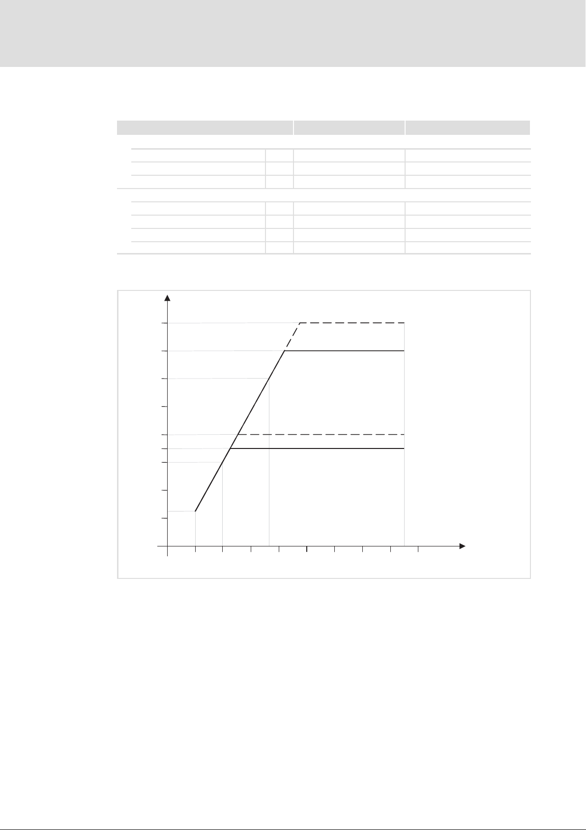
4.2.3 DC/DC converter
DC/DC converter 2.8 kW 5.6 kW
Input data − HV on−board supply system
Rated voltage V DC 800 800
Voltage range V DC 100...848 100...848
Max. current consumption A 16.5 18.3
Output data
Max. output power kW 2.8 5.6
Rated output voltage V DC 14 28
Output voltage range V DC 6 ... 16 6 ... 32
Max. output current A 200 200
Diagram of the output voltage of the DC/DC converter
U [V]
LV,out
32
28
24
EMDAGxxxxxxxC...
EMDAGxxxxxxxC...
U
max
U
N
20
16
14
12
EMDAGxxxxxxxT...
EMDAGxxxxxxxT...
8
4
360 V
0
100 200 300 400 500 600 700 800 900
U
max
U
N
850 V
Fig. 4−1 DC/DC converter: output voltage with reference to the HV on−board voltage
V
V
V
V
HV,in
LV,o ut
rated
max
Voltage of HV on−board supply system
Output voltage of DC/DC converter
Rated output voltage
Max. output voltage
U [V]
HV,in
EMDAG0043b
30
Ò
EDSMDAG EN 2.0
Page 31
4.3 Control of MOBILE DCU, PSU, DCU PSU
The MOBILE device is controlled via the X31 terminal.
4.3.1 Voltage supply
Technical data
Control of MOBILE DCU, PSU, DCU PSU
Voltage supply
4
Voltage supply
Supply voltage TRM30
Rated voltage
Voltage range V DC 8 ... 36 8 ... 36
Absolute voltage
(Pulse forms: ISO 16750−2)
(Behaviour: ISO 16750−1)
Current consumption A 1 ... 2.5 0.5 ... 1.3
Quiescent current at T
Switch on/off device TRM15
Switching threshold V DC 8 8
Current consumption mA 1.7 1.7
4.3.2 Digital inputs
Digital inputs
Rated input voltage V DC 12 24
Voltage range V DC 8 ... 36 8 ... 36
Digital HIGH V DC 7.8 ... 9 15.6 ... 18.2
Digital LOW V DC 3 ... 4.5 6.2 ... 8.8
Hysteresis V DC 3.3 ... 6 6.8 ... 12
Input resistance kW 4.75
Reference potential TRM31
Diagnostics option Wire breakage/short circuit
Digital frequency inputs FLX_IN3, FLX_IN4
Frequency range kHz 0 ... 10
Response time ms 90
Analog inputs FLX_IN1, FLX_IN2
Input frequency Hz 0 ... 500
Resolution Bit 4096
LV on−board supply system
12 V 24 V
V DC 12 24
Min. V DC 6 6
Max. V DC 60 60
= 25 °C mA 40 ... 60 40 ... 60
amb
LV on−board supply system
12 V 24 V
EDSMDAG EN 2.0
Ò
31
Page 32
4
Technical data
Control of MOBILE DCU, PSU, DCU PSU
Digital outputs
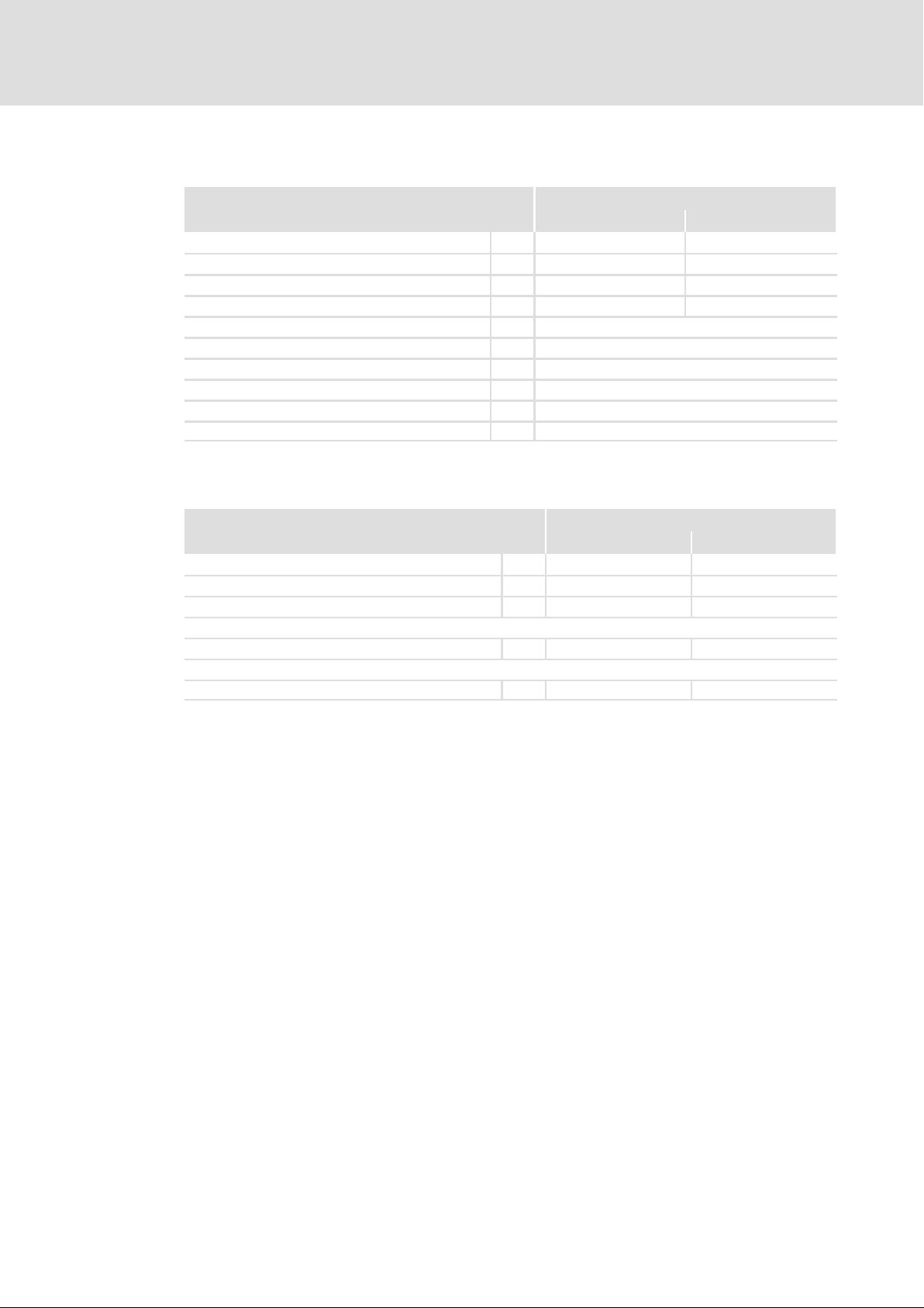
4.3.3 Digital outputs
Digital outputs
Rated output voltage V DC 12 24
Voltage range V DC 8 ... 36 8 ... 36
Digital HIGH V DC 8 ... 10.8 ³21.6
Digital LOW V DC 0 ... 5 0 ... 5
Output current HIGH A 0 ... 2
Output current LOW A 0 ... −0.5
Output frequency kHz 0 ... 1
Response time ms 95
Reference potential TRM31
Diagnostics option Wire breakage/short circuit
4.3.4 Potential−free output
Digital switching output
Max. switching voltage V DC 60 60
Voltage potential to X31/20, X31/21 V DC −60 ... 60 −60 ... 60
Max. permissible capacitive load
InterLock−OK (closed)
Contact resistance W 6 ... 15 6 ... 15
InterLock−NOK (open)
Max. fault current mA 1 1
1)
In case of a higher capacitive load, provide for an external current limitation, e.g. by means of a resistor in series
connection
LV on−board supply system
12 V 24 V
LV on−board supply system
12 V 24 V
1)
mF 22 22
32
Ò
EDSMDAG EN 2.0
Page 33

Technical data
Control of MOBILE DCU, PSU, DCU PSU
CAN bus
4
4.3.5 CAN bus
Public CAN
Protocol
Baud rate kbps 125, 250, 500
Max. cable length
at 125kbps S 250
at 250kbps m 250
at 500kbps m 100
Loop delay of all nodes ns <300
Private CAN
Protocol CANopen
Baud rate kbps 125, 250, 500, 1000
Max. cable length
at 125kbps m 250
at 250kbps m 250
at 500kbps m 100
at 1000kbps m 20
Loop delay of all nodes ns <300
SAE J1939
EDSMDAG EN 2.0
Ò
33
Page 34
4
Technical data
Control of MOBILE DCU S
Voltage supply
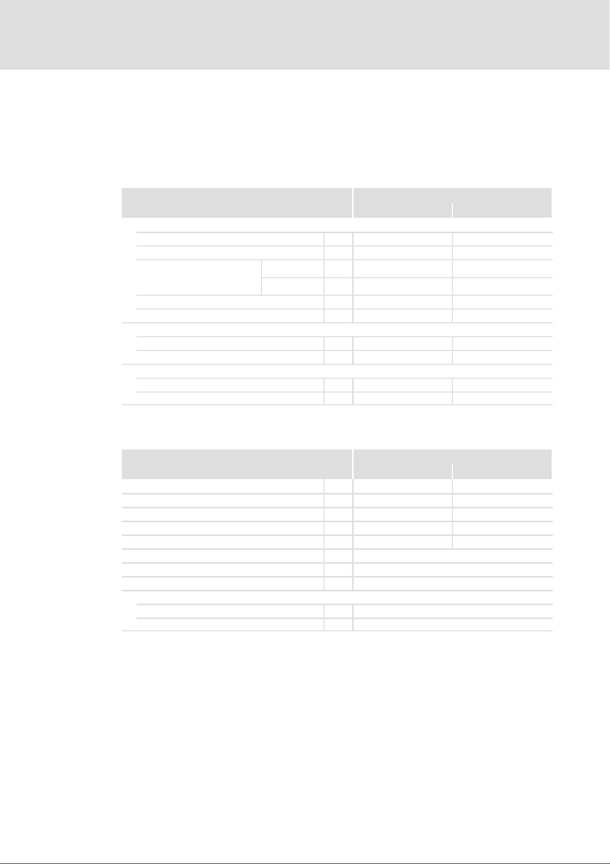
4.4 Control of MOBILE DCU S
The MOBILE device is controlled via the X1 terminal.
4.4.1 Voltage supply
Voltage supply
Supply voltage TRM30
Rated voltage
Voltage range V DC 8 ... 36 8 ... 36
Absolute voltage
(Pulse forms: ISO 16750−2)
(Behaviour: (ISO 16750−1)
Current consumption A 0.4 ... 0.9 0.2 ... 0.6
Quiescent current at T
Switch on/off device TRM15
Switching threshold V DC 8 8
Current consumption mA 1.7 1.7
Secondary Wake Up (SWUP)
Switching threshold V DC 8 8
Current consumption mA 1.7 1.7
4.4.2 Digital inputs
Digital inputs
Rated input voltage V DC 12 24
Voltage range V DC 8 ... 36 8 ... 36
Digital HIGH V DC 7.8 ... 9 15.6 ... 18.2
Digital LOW V DC 3 ... 4.5 6.2 ... 8.8
Hysteresis V DC 3.3 ... 6 6.8 ... 12
Input resistance kW 4.75
Reference potential TRM31
Diagnostics option Wire breakage/short circuit
Use as analog inputs
Input frequency Hz 0 ... 500
Resolution Bit 4096
LV on−board supply system
12 V 24 V
V DC 12 24
Min. V DC 6 6
Max. V DC 60 60
= 25 °C mA 40 ... 60 40 ... 60
amb
LV on−board supply system
12 V 24 V
34
Ò
EDSMDAG EN 2.0
Page 35
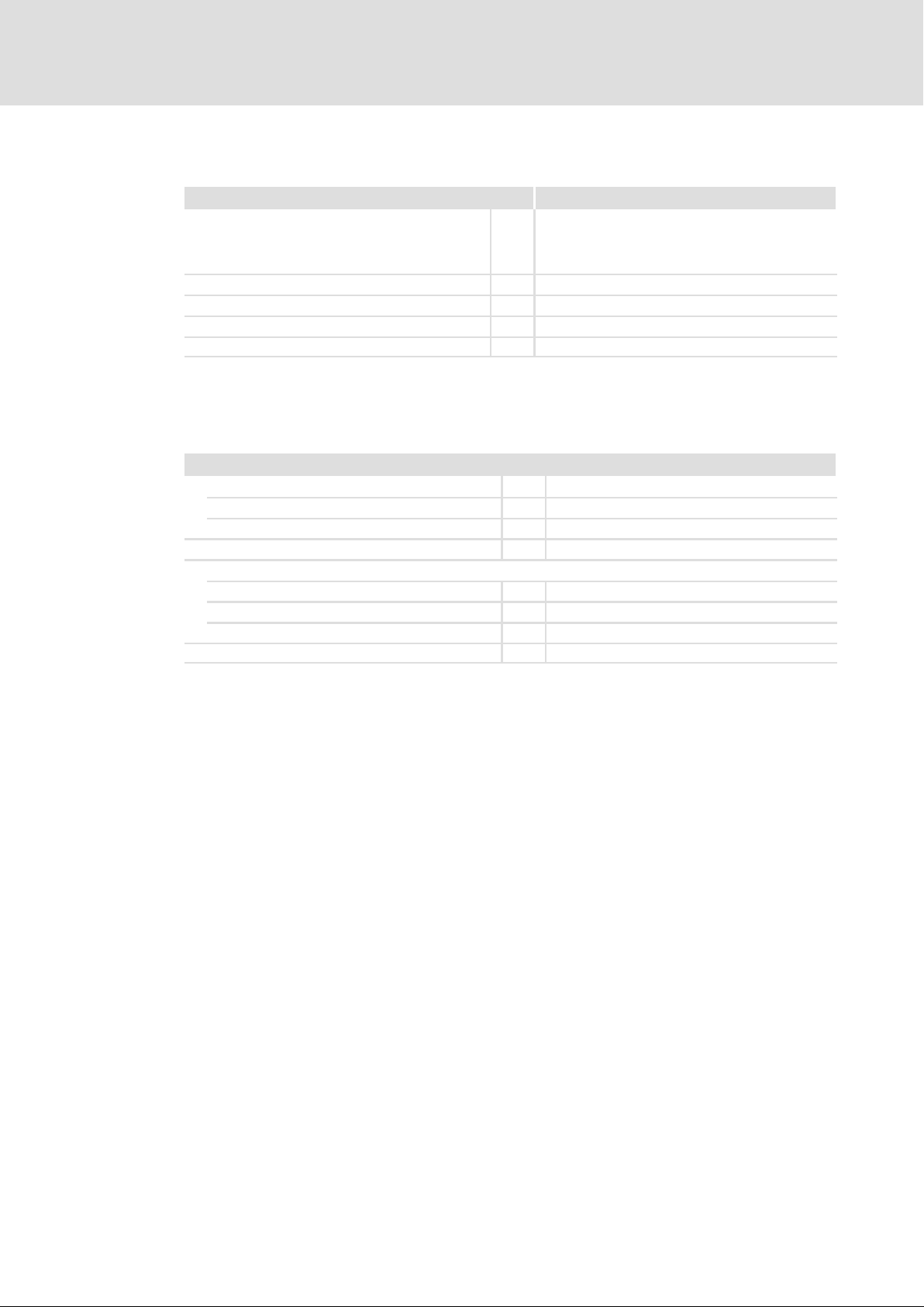
4.4.3 Thermal sensor input
Thermal sensor input Value
Evaluable thermal sensors PT1000, KTY83/110, KTY84/130,
Diagnostics option Wire breakage/short circuit
Resistance measuring range W 280 ... 3050
Limit frequency of input filter Hz 10
Resolution Bit 12
4.4.4 CAN bus
Public CAN and Private CAN communicate via a bus cable.
Public CAN, Private CAN
Protocol
Public CAN SAE J1939
Private CAN CANopen
Baud rate kbps 125, 250, 500
Max. cable length
at 125kbps m 250
at 250kbps m 250
at 500kbps m 100
Loop delay of all nodes ns <200
Technical data
Control of MOBILE DCU S
Thermal sensor input
PTC acc. to DIN44081,
thermostat (normally−closed contact) acc. to
DIN44080
4
EDSMDAG EN 2.0
Ò
35
Page 36
4
Technical data
Water cooling
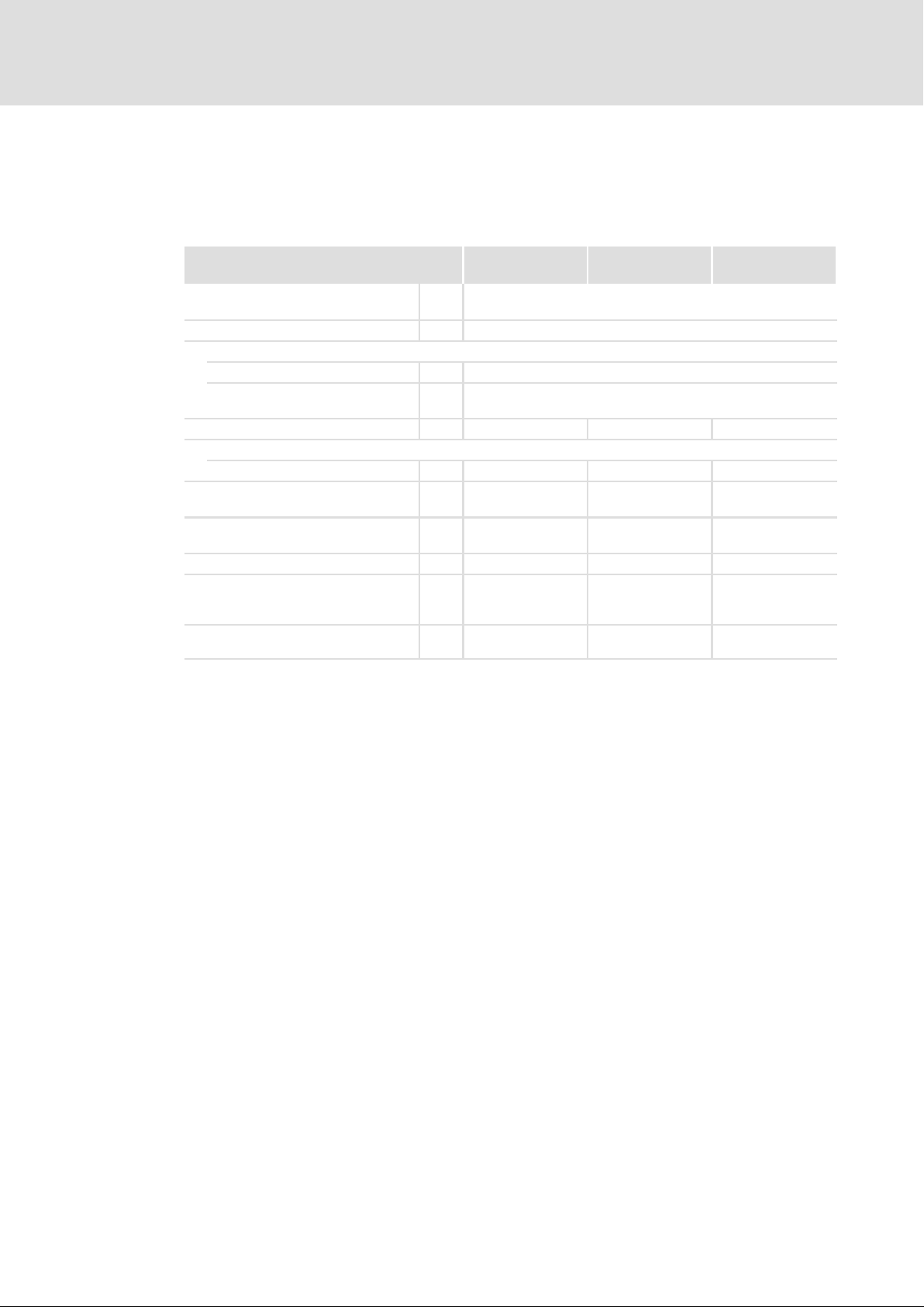
4.5 Water cooling
For cooling the MOBILE device, the integrated water cooler is connected to the
vehicle−specific cooling circuit.
EMDAG2... EMDAG3...
EMDAG4...
Connection of suction and pressure
hoses
Securing the hoses Suitable hose clamps
Flow direction
in case of vertical installation from the lower to the higher connection
in case of horizontal or pending
installation
Fluid volume l 0.09 0.16 0.12
Composition of the cooling fluid
Water/ethylene glycol % 50/50 50/50 50/50
Flow rate
Derating at a lower flow rate
Permissible pressure in the cooling
system
Max. test pressure bar 5 5 5
Permissible temperatures of the
cooling fluid
in continuous operation
Recommended switch−on temperature
for coolant pump
l/min 15 ... 25 15 ... 25 15 ... 25
bar 1 ... 2 1 ... 2 1 ... 2
°C 30 ... 65 30 ... 65 30 ... 65
°C 30 30 30
DN 20 (internal)
Not relevant
EMDAG5...
36
Ò
EDSMDAG EN 2.0
Page 37
Technical data
Water cooling
Decrease in pressure in the water cooler
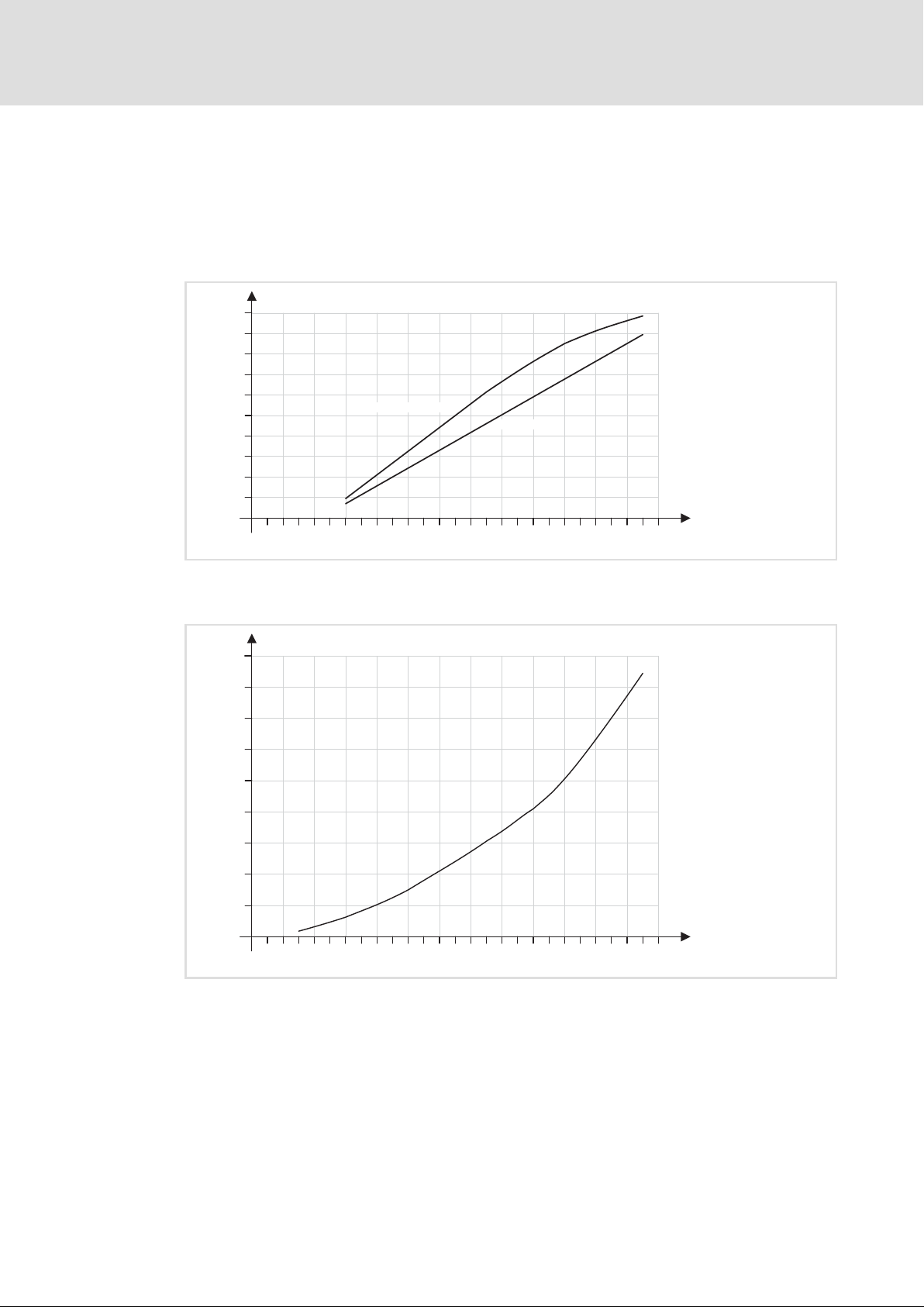
Decrease in pressure in the water cooler of the MOBILE device with a coolant mixture of
water/ethylene glycol in a ratio of 50:50 and at a coolant temperature of 60°C.
MOBILE DCU, PSU, DCU PSU
p [mbar]
100
90
80
70
60
50
40
30
20
10
MOBILE PSU, DCU PSU
MOBILE DCU
4
0 510 15 20
Fig. 4−2 Typical decrease in pressure in the water cooler
MOBILE DCU S
p [mbar]
45
40
35
30
25
20
15
10
5
0 510 15 20
Fig. 4−3 Typical decrease in pressure in the water cooler
25
25
Q [l/min]
EMDAG030
Q [l/min]
EMDAG048
EDSMDAG EN 2.0
Ò
37
Page 38

4
4.6 Dimensions
Technical data
Dimensions
Dimensions and weights can be found in the "Mechanical installation" chapter. (¶ 41)
38
Ò
EDSMDAG EN 2.0
Page 39

5 Installation
5.1 Important notes
{ Danger!
Dangerous electrical voltage
Even after the HV on−board voltage or mains voltage has been switched off, all
power terminals continue to carry electrical voltage for some time, e.g. from
capacitors.
Possible consequences:
ƒ Death or severe injury if the power terminals are touched.
Protective measures:
ƒ Switch off the HV on−board supply system or power supply and wait until
the power terminals are discharged before working on them.
ƒ Make sure that all power terminals are deenergised before working on
them.
Installation
Important notes
5
( Stop!
No device protection if the HV on−board voltage or mains voltage is too high
The input for the HV on−board supply system or the mains is not fused
internally.
Possible consequences:
ƒ Destruction of the device if the HV on−board voltage or the mains voltage is
too high.
Protective measures:
ƒ Observe the maximum permissible HV on−board voltage or mains voltage.
ƒ Fuse the device correctly on the supply side against mains fluctuations and
voltage peaks.
( Stop!
The input for the HV on−board supply system or the mains does not have an
electrical polarity reversal protection
Possible consequences:
ƒ Destruction of the device is the HV on−board supply system or the mains is
connected incorrectly.
Protective measures:
ƒ Check wiring for possible polarity reversal.
EDSMDAG EN 2.0
Ò
39
Page 40

5
Installation
Important notes
( Stop!
The device contains components that can be destroyed by electrostatic
discharge!
Before working on the device, the personnel must ensure that they are free of
electrostatic charge by using appropriate measures.
40
Ò
EDSMDAG EN 2.0
Page 41
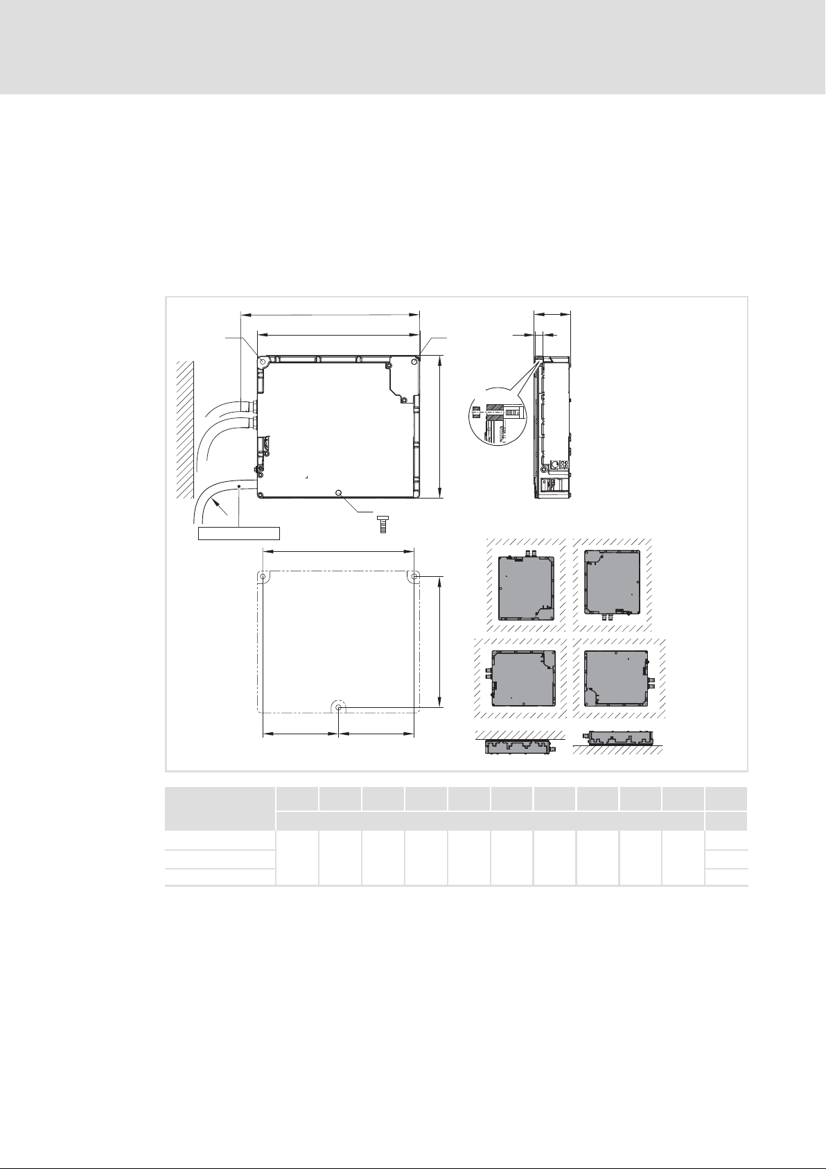
5.2 Mechanical installation
EMDAG2..., EMDAG3..., EMDAG4...
The mounting material must ensure a durable mechanical connection. The fixing points
are dimensioned for:
ƒ M10 cheese head screw, hexagon socket, according to DIN 912/ISO 4762
ƒ M10 cheese head screw, torx, according to ISO 14579
Installation
Mechanical installation
5
g
3
r
X11 / X12 / X13
b
b
1
g
3
M10
3×
c
3
g
3
3×
h
3
d
t
g
EDSMDAG EN 2.0
c
4
h b t b
c
5
EMDAG002
c
1
c
3
c
4
d
5
g
3
r Ý
3
[mm] [kg]
EMDxG2...
EMDxG3... 8.4
310
394 81 355 331 165.5 165.5 286 Ø 11 106
7.0
EMDxG4... 8.4
Ò
41
Page 42
5
Installation
Mechanical installation
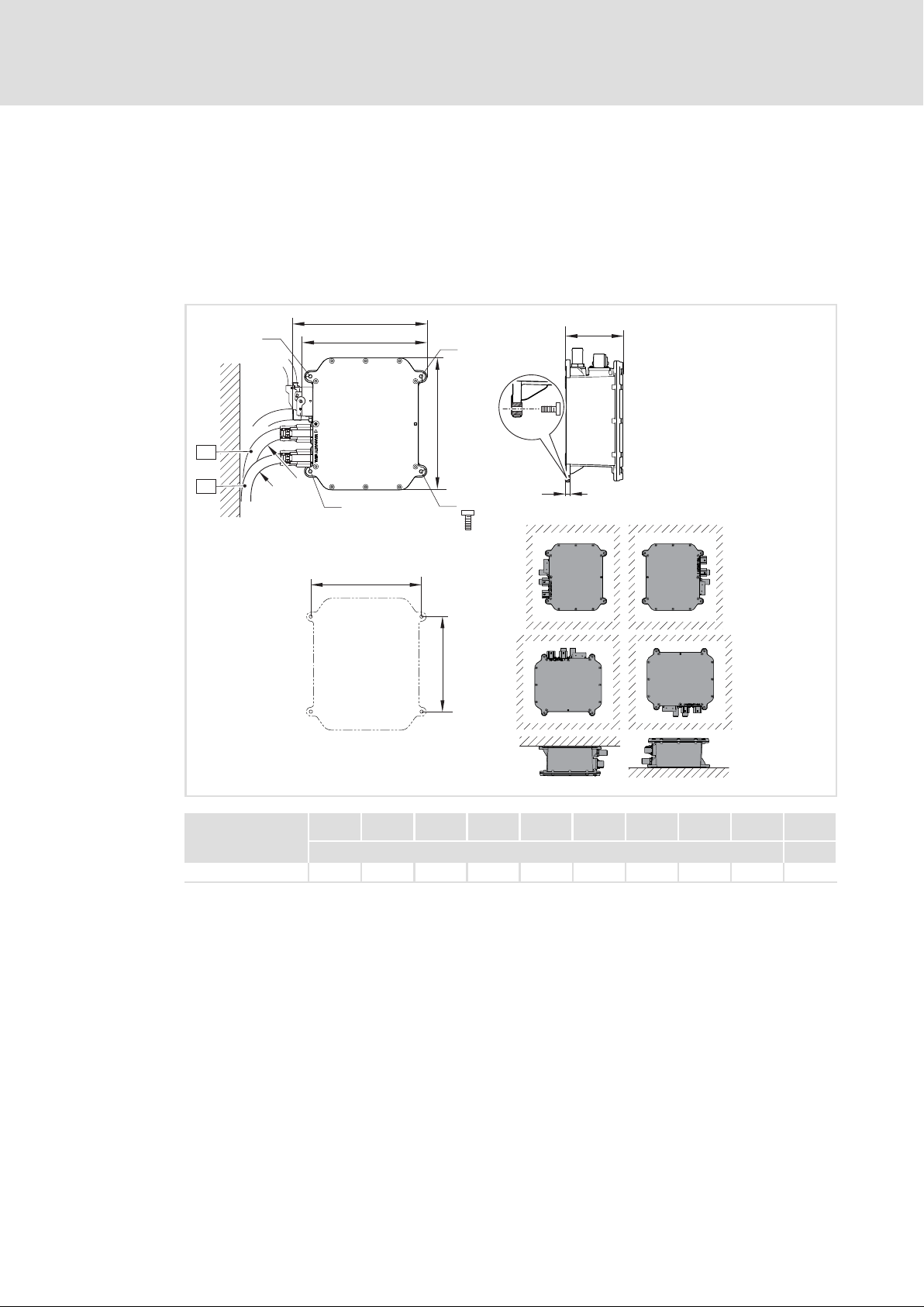
EMDAG5...
The installation material must ensure the mechanical connection on a permanent basis.
The fixing points are designed for:
ƒ M6 cheese head, hexagon socket, acc. to DIN 912/ISO 4762
ƒ M6 cheese head, Torx, acc. to ISO 14579
X2
X3
g
3
r
r
b
b
1
g
3
c
3
g
3
h
g
3
M6
4×
3
d
t
g
EMDAG026
h b t b
c
1
d
3
3
g g
3
r Ý
[mm] [kg]
EMDxG5... 250 254 109 237 210 180 9 Ø 6.7 106 3.9
42
Ò
EDSMDAG EN 2.0
Page 43
5.3 Water cooling
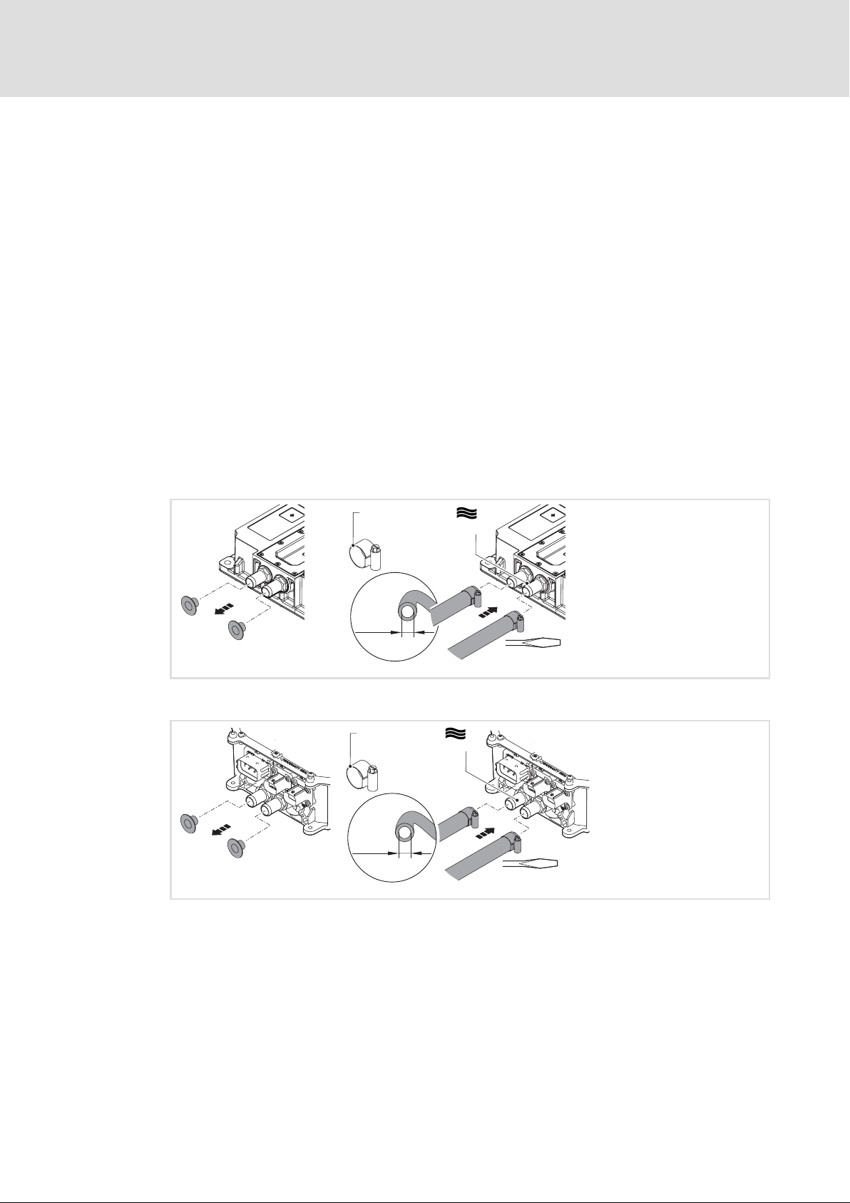
For operating the Mobile devices, a working water cooling system is required.
Operation without water cooling is not permissible and destroys the devices.
A subsequent loosening or tightening of the screws in the cooling cover is not permissible.
The water cooler is mounted in the factory and checked for tightness.
The water cooling has to be dimensioned according the technical data (¶ 36).
How to connect a proper cooling system:
ƒ Remove the protective caps from the adaptors (delivery status).
ƒ Connect suction and pressure hoses.
ƒ Fix and secure the hoses with suitable clips.
ƒ Fill and vent water cooling.
Prior to every switch−on, the proper functioning of the cooling needs to be ensured.
Installation
Water cooling
5
EMDAG2..., EMDAG3..., EMDAG4...
Æ 25 - 40 mm
1.
20 mm
(DN 20)
EMDAG5...
Æ 25 - 40 mm
1.
20 mm
(DN 20)
£ 2 bar
2.
8 × 1.2 mm
EMDAG004
£ 2 bar
2.
8 × 1.2 mm
EMDAG027
EDSMDAG EN 2.0
Ò
43
Page 44
5
Installation
EMC−compliant installation
Equipotential bonding
5.4 EMC−compliant installation
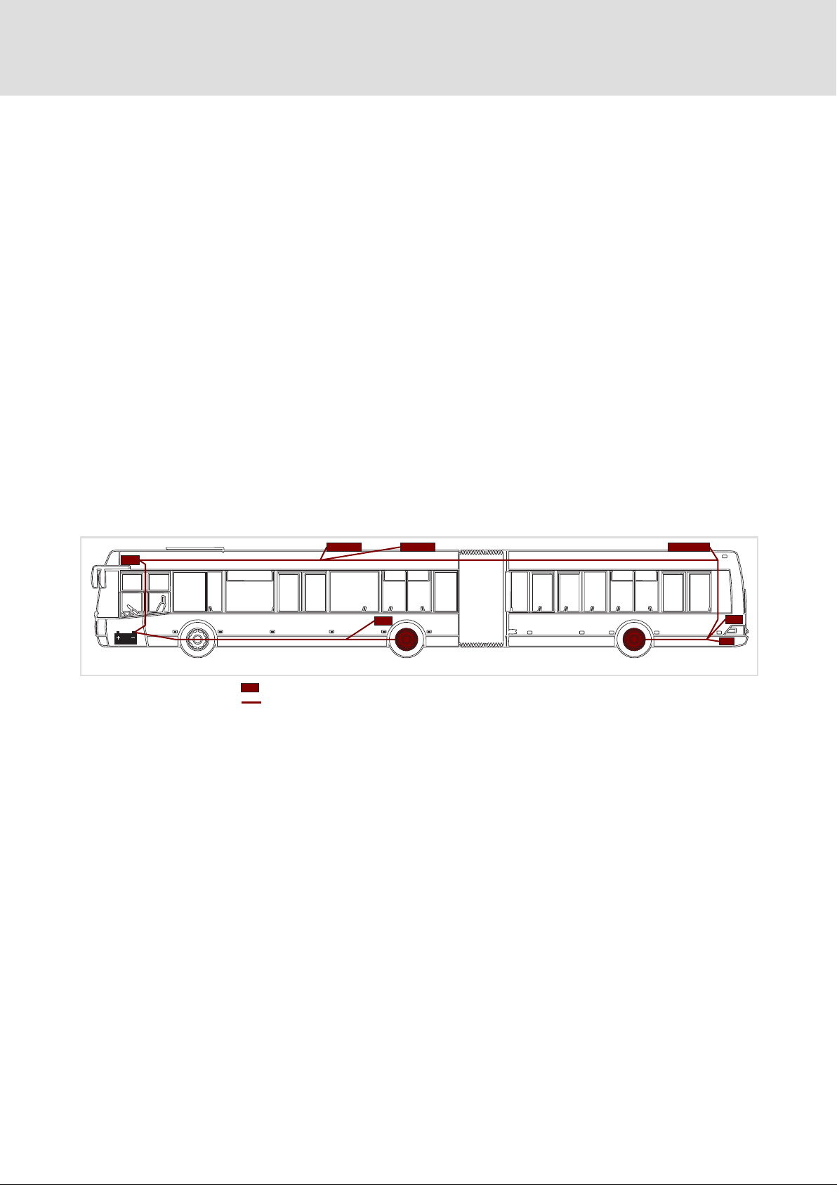
EMC−compliant installation is a prerequisite for a safe and trouble−free operation of the
devices.
EMC interferences can
ƒ interrupt the CAN communication,
ƒ cause the drives and on−board converters to be switched off to protect the systems.
5.4.1 Equipotential bonding
Conditions for a working EMC concept:
ƒ Avoid current loops because they cause induced voltage differences.
ƒ Arrange the equipotential bonding in star shape and avoid earth loops.
ƒ Install equipotential bonding conductors in parallel to the supply and
communication cables.
– A equipotential bonding conductor in the motor cable extends the current
compensation by high−frequency currents and avoids an overload of the cable
shield.
MOBILE device
Equipotential bonding conductor
EMDAG041
44
Ò
EDSMDAG EN 2.0
Page 45

5.4.2 Shielding
ƒ The effectiveness of a shielded cable is reached by:
– Providing a good shield connection through large−surface shield contact.
– Using only braided shields with low shield resistance made of tin−plated or
nickel−plated copper braid.
– Using braided shields with an overlap rate > 70 % and an overlap angle of 90 °.
– Keeping unshielded cable ends as short as possible.
Use system cables or shielded cables for these connections:
ƒ Motor
ƒ HV on−board supply system
The following connections need not be shielded:
ƒ LV on−board supply system (only PSU)
ƒ 24−V supply
Installation
EMC−compliant installation
Shielding
5
ƒ Digital signals (inputs and outputs).
– We recommend to use shielded cables for a cable length from approximately 5 m
on or in environments with strong interferences.
Connection system
Prefabricated cables for the motor connection and the connection to the HV on−board
supply system are provided with cable glands and ensure an optimum connection of the
shield to the vehicle mass. This guarantees an optimum EMC−compliant installation and
the required environmental conditions are met.
ƒ When installing the motor cable and the HV on−board cable, slide the cable gland
into the respective holders and fix it by tightening the mounting bracket.
5.4.3 HV on−board cable
The descriptions in the next chapter regarding shielded motor cables analogously also
apply to the HV mains cables (see next chapter).
EDSMDAG EN 2.0
Ò
45
Page 46

5
5.4.4 Motor cable
Installation
EMC−compliant installation
Motor cable
ƒ Only use shielded motor cables with braids made of tinned or nickel−plated copper.
Shields made of steel braids are not suitable.
– The overlap rate of the braid must be at least 70 % with an overlap angle of 90 °.
ƒ The cables used must correspond to the requirements at the location (e.g.
EN 60204−1).
ƒ Use Lenze system cables.
ƒ Extensively apply the shielding with the compressed cable gland and ensure
electrical conductivity.
ƒ The motor cable is optimally installed if
– it is separated from mains cables and control cables,
– it only crosses mains cables and control cables at right angles,
– it is not interrupted.
ƒ If the motor cable must be opened all the same (e.g. due to contactors, or terminals):
– The unshielded cable ends may not be longer than 100 mm (depending on the
cable cross−section).
– Install contactors, terminals etc. spatially separated from other components (with
a min. distance of 100 mm).
– Install the shield of the motor cable directly before and behind the point of
separation to the conducting mounting plate with a large surface.
ƒ Connect the shield with a large surface to PE in the terminal box of the motor at the
motor housing.
– Metal EMC cable glands at the motor terminal box ensure a large surface
connection of the shield with the motor housing.
Wiring on the motor side
( Stop!
The motor cable is highly susceptible to interference. The following measures
enable you to achieve an optimum wiring on the motor side:
ƒ Exclusively use shielded and low−capacitance motor cables.
ƒ If possible, integrate the equipotential bonding conductor inside the motor
cable shield or install it in parallel to the motor cable.
ƒ Do not integrate any further cables (e.g. for blowers etc.).
ƒ Shield the supply cable for temperature monitoring of the motor (PTC or
thermostat) and install it separately from the motor cable.
46
Ò
EDSMDAG EN 2.0
Page 47
5.4.5 Control cables
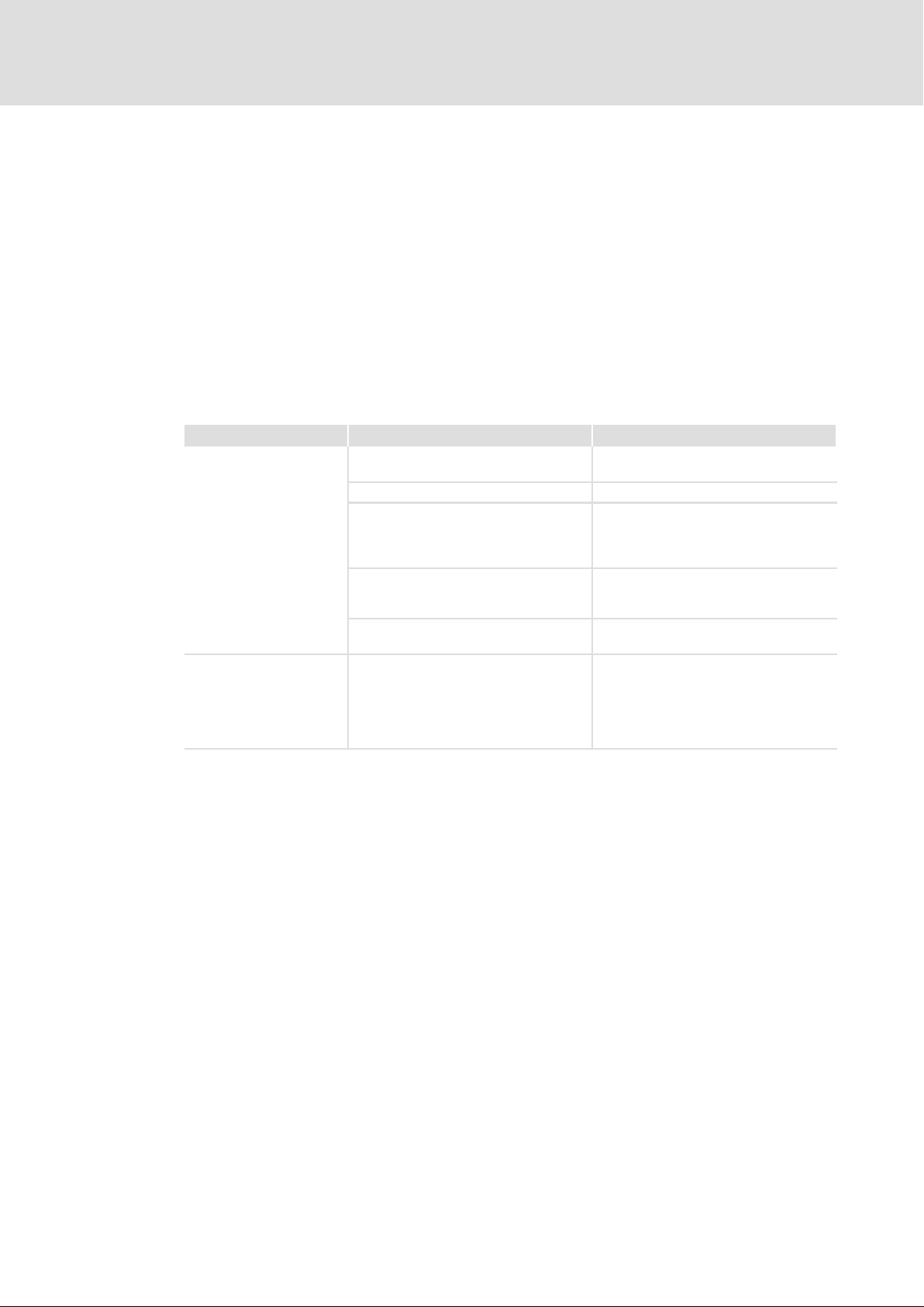
ƒ Shield control cables to minimise interference injections.
ƒ Connect the shield correctly:
– Connect the shield of digital input and output cables at both ends.
– Connect the shield of analog input and output cables at one end of the inverter.
ƒ To achieve an optimum shielding effect (in case of very long cables, with high
interference) one shield end of analog input and output cables can be connected to
PE potential via a capacitor (e.g. 10 nF/250 V).
5.4.6 Detecting and eliminating EMC interferences
Interference Cause Remedy
Interference of analog
setpoints of the own or
other devices and
measuring systems
CAN time out
or
CAN Bus Heavy
Unshielded HV mains cable
Unshielded motor cable
Shield contact is not extensive enough Carry out optimal shielding as specified
Shield of the motor cable is interrupted
by terminal strips, switched, etc.
Install additional unshielded cables
inside the motor cable (e.g. for motor
temperature monitoring)
Too long and unshielded cable ends of
the motor cable
CAN communication is disturbed l Use cable according to CAN
Installation
EMC−compliant installation
Control cables
Use shielded cables
l Separate components from other
component parts with a minimum
distance of 100 mm
l Use motor choke/motor filter
Install and shield additional cables
separately
Shorten unshielded cable ends to
maximally 40 mm
specification
l Wire terminals completely
l Connect the shield with a good
electric conductivity
l Check terminating resistor
5
EDSMDAG EN 2.0
Ò
47
Page 48
5
Installation
Electrical installation
Basic circuit diagrams
5.5 Electrical installation
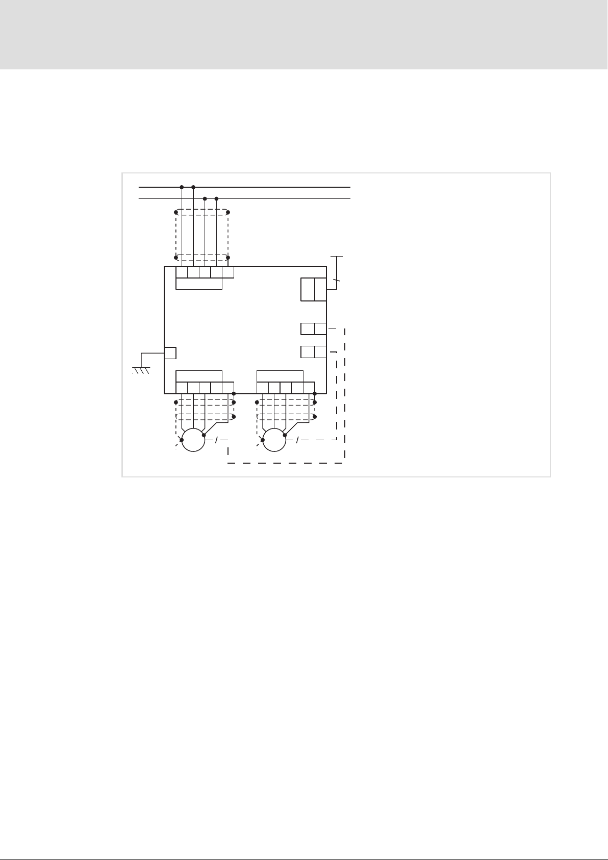
5.5.1 Basic circuit diagrams
MOBILE DCU
800 V DC
+
-
Strg
+UG +UG -UG -UG
+
VW
3~
M
+
X11
X12
+
X31
EMDxG2...
+
U
3~
8
+
X13
VW
M
X32
X33
+
U
8
26
1
...
26
1
...
8
1
...
8
EMDAG0038a
48
Ò
EDSMDAG EN 2.0
Page 49
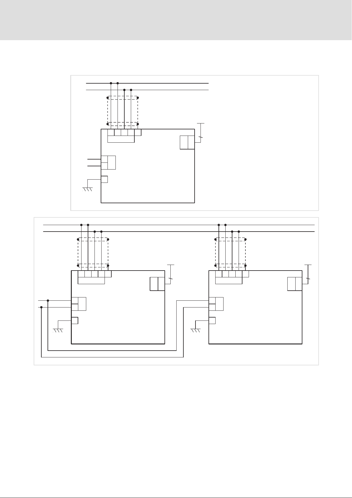
MOBILE PSU
800 V DC
+
-
Strg
Installation
Electrical installation
Basic circuit diagrams
5
800 V DC
+
-
12/24 V DC
+
-
12/24 V DC
+
-
+UG +UG -UG -UG
X11
+B
X21
-B
+UG +UG -UG -UG
X11
+B
X21
-B
+
++
EMDxG3...
+
EMDxG3...
26
1
...
X31
26
Strg Strg
+UG+UG -UG -UG
X11
+B
X21
-B
EMDxG3...
X31
26
1
...
26
12/24 V DC
+
-
X31
EMDAGS0038b
1
...
26
26
EDSMDAG EN 2.0
+
Ò
+
EMDAG0038c
49
Page 50
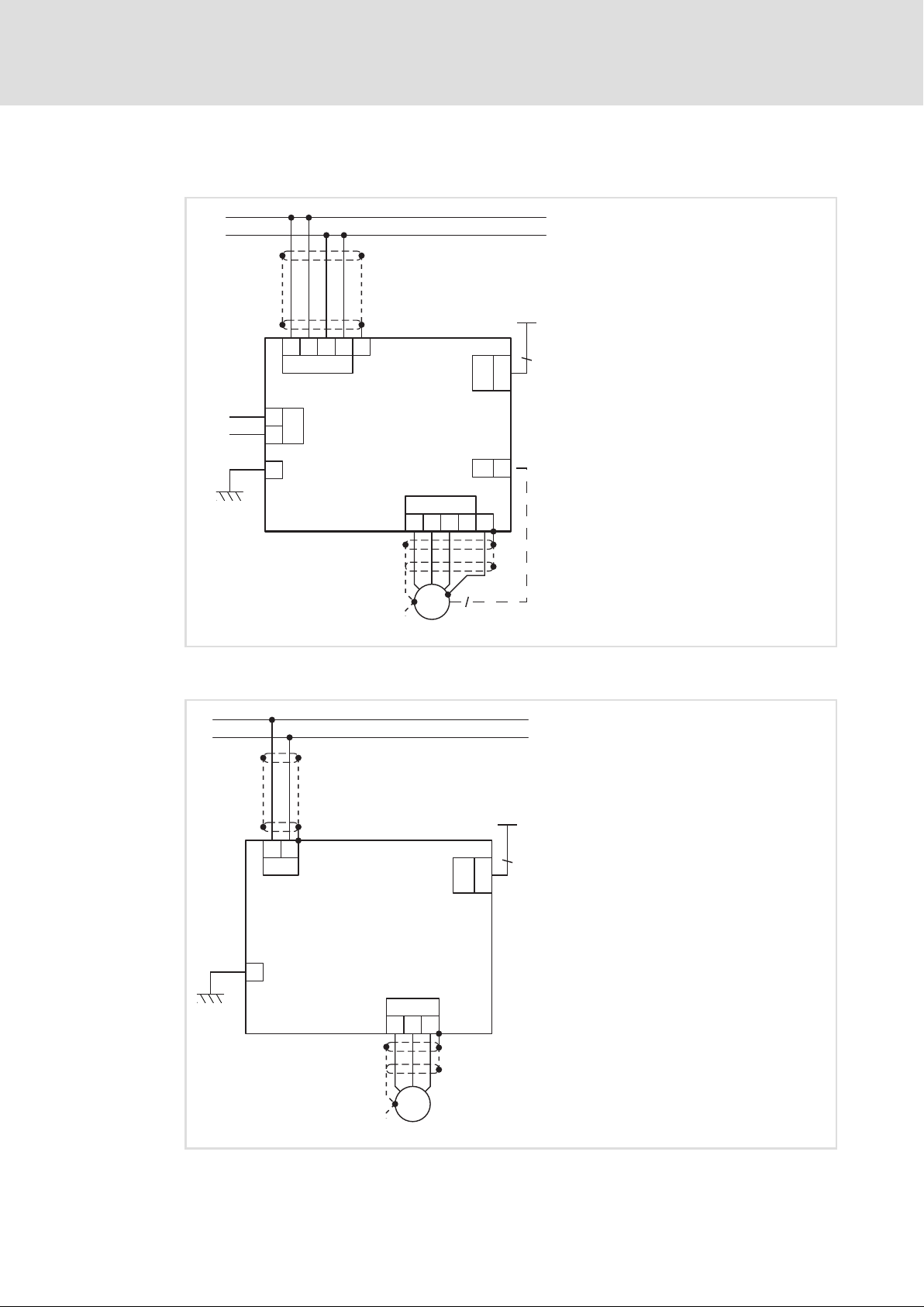
5
Installation
Electrical installation
Basic circuit diagrams
MOBILE DCU PSU
800 V DC
+
-
Strg
12/24 V DC
+
+B
-
-B
+
MOBILE DCU S
800 V DC
+
-
+UG +UG -UG -UG
X11
X21
+
EMDxG4...
26
1
...
X31
26
1
...
X33
8
X13
+
U
VW
3~
M
+
8
EMDAG0038d
50
+
+UG -UG
X2
EMDxG5...
X3
+
VW
3~
M
U
Ò
X1
Strg
20
1
...
21
EMDAG0038e
EDSMDAG EN 2.0
Page 51

Installation
Electrical installation
Fuses and cable cross−sections
5
5.5.2 Fuses and cable cross−sections
Installed cables have to be protected against short circuit and overload. The execution of
these protective measures essentially depends on the available energy sources (generator,
memory, connection to supply system, etc.) and is the responsibility of the vehicle
manufacturer or the equipment suppliers.
Fuses and circuit breakers have to be dimensioned in such a way that the occurring
short−circuit currents caused by the internal resistances of the energy sources are
sufficiently high to safely trip the fuses. Otherwise, there is no reliable switch−off in case
of short circuit.
When dimensioning fuses, consider the ambient conditions in such a way that the cables
are protected from overload in the entire temperature range. Here, the type of installation
and cooling of the cables have to be considered sufficiently.
If a memory with battery management is available that can switch off the short−circuit
current reliably, no fuses are needed. In this case, the cables of the MOBILE devices have to
be protected from overload by a suitable parameter setting.
EDSMDAG EN 2.0
Ò
51
Page 52
5
Installation
Electrical installation
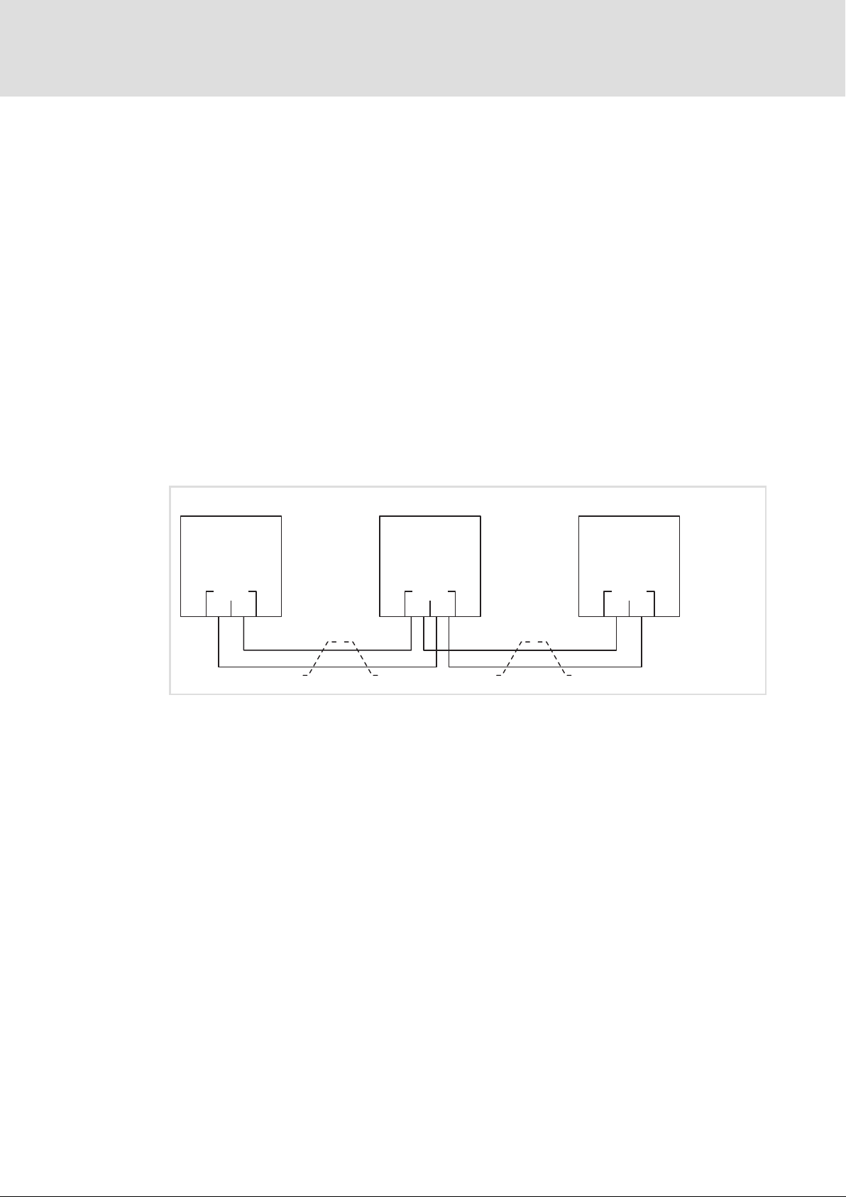
Wiring the CAN bus
5.5.3 Wiring the CAN bus
Wiring must meet the following requirements:
ƒ The CAN cable complies with the specification acc. to ISO 11898−2.
ƒ The CAN cable has twisted cores (CAN_H, CAN_L) to avoid interferences on the bus
(Bus−Off, Bus−Heavy, etc).
ƒ When looping through the signals "CAN_HIGH" and "CAN_LOW", avoid double
crimping. For this purpose, the Public CAN is provided with two pins each.
ƒ Stubs are <0.2m. Ideally, stubs are avoided.
ƒ The cable length matches the data transfer rate.
ƒ The CAN cable runs along the LV on−board cable and is installed separately from the
power cables.
ƒ The CAN bus is completely wired. Unwired terminals are not permissible.
ƒ The first and last node of the CAN bus are connected to the integrated terminating
resistor.
HCU
MOBILE 1
MOBILE 2
CAN
High
Low
CAN
CAN
EMDAG0034a
52
Ò
EDSMDAG EN 2.0
Page 53
Installation
Electrical installation
Wiring the CAN bus
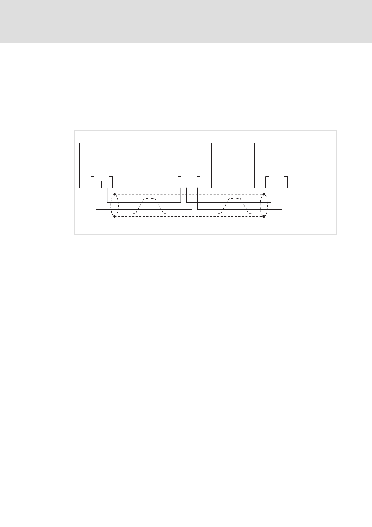
Interferences on the CAN bus
In case of interferences on the CAN bus, a shielded cable must be used. The shield is
connected to PE (chassis ground). The shield/PE connection must have a low resistance to
avoid shield currents in the system.
ƒ Connect the shield on one side to PE.
ƒ Connect the shield on both sides to PE if interferences continue to occur in case the
shield is only connected on one side.
5
HCU
CAN
+
High
Low
MOBILE 1
CAN
MOBILE 2
CAN
+
EMDAG0034b
EDSMDAG EN 2.0
Ò
53
Page 54
5
Installation
Connections of MOBILE DCU, PSU, DCU PSU
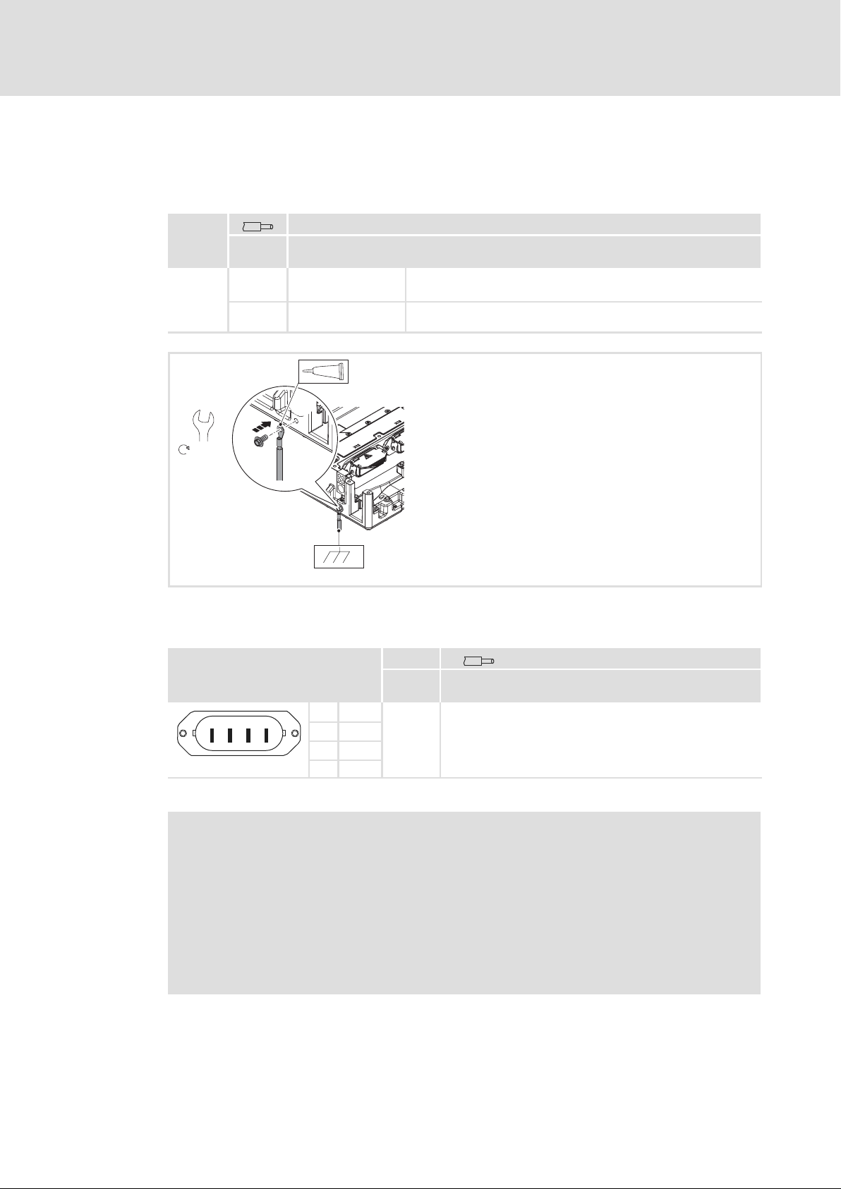
PE conductor
5.6 Connections of MOBILE DCU, PSU, DCU PSU
5.6.1 PE conductor
PE
[mm2]
[AWG]
+
8 (Eco-Fix)
10
6.3 Nm
>10
>000
MOBILE DCU Same conductor cross−section as the HV on−board cable
Connection with non−insulated ring cable lug, M6
MOBILE DCU PSU
MOBILE PSU
xxxxx
DC4
xxxxxxxx
Connection with non−insulated ring cable lug, M6
+
xxxxx
xxxxxxxx
5.6.2 HV on−board supply system
X11
2
3
1
Per potential, the terminal contains two contacts for looping through the DC−bus voltage.
4
EMDAG020b
1 +UG
2 +UG
3 −UG
4 −UG
( Stop!
The input for the HV on−board supply system or the mains does not have an
electrical polarity reversal protection
Possible consequences:
ƒ Destruction of the device is the HV on−board supply system or the mains is
connected incorrectly.
Protective measures:
ƒ Check wiring for possible polarity reversal.
U
max
[V DC] [mm2]
[AWG]
848
2.5 ... 12
12 ... 6
EMDAG017a
54
Ò
EDSMDAG EN 2.0
Page 55
Installation
Connections of MOBILE DCU, PSU, DCU PSU
Motor
5
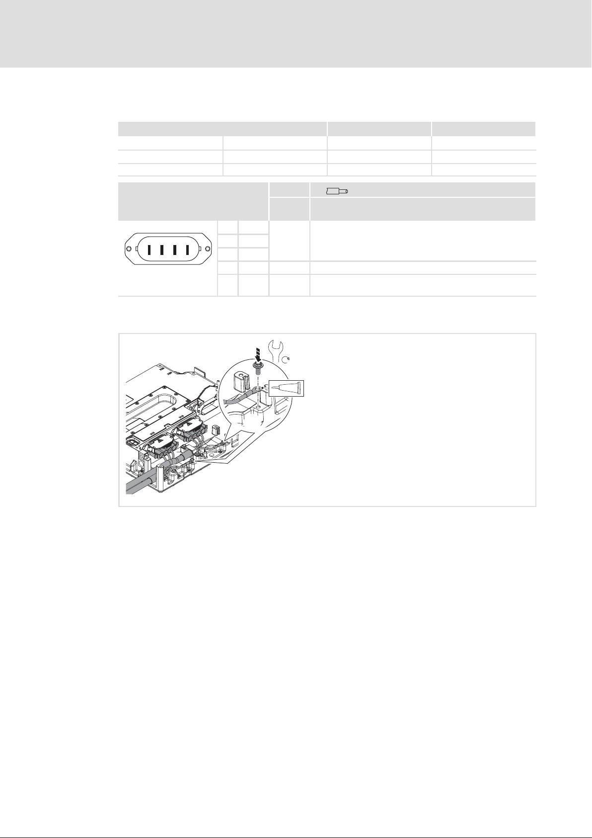
5.6.3 Motor
X12 X13
MOBILE DCU EMDxG2... l l
MOBILE PSU EMDxG3... ˘ ˘
MOBILE DCU PSU EMDxG4... ˘ l
X12, X13
PE conductor
U
max
[V AC] [mm2]
[AWG]
1 W
2
3
1
4
EMDAG020b
2 V
3 U
4 ˘ ˘ ˘
+
PE ˘
600
8
3.6 Nm
2.5 ... 12
12 ... 6
2.5 ... 12
12 ... 6
+
xxxxx
DC4
xxxxxxxx
EMDAG005a
EDSMDAG EN 2.0
Ò
55
Page 56
5
Installation
Connections of MOBILE DCU, PSU, DCU PSU
Feedback
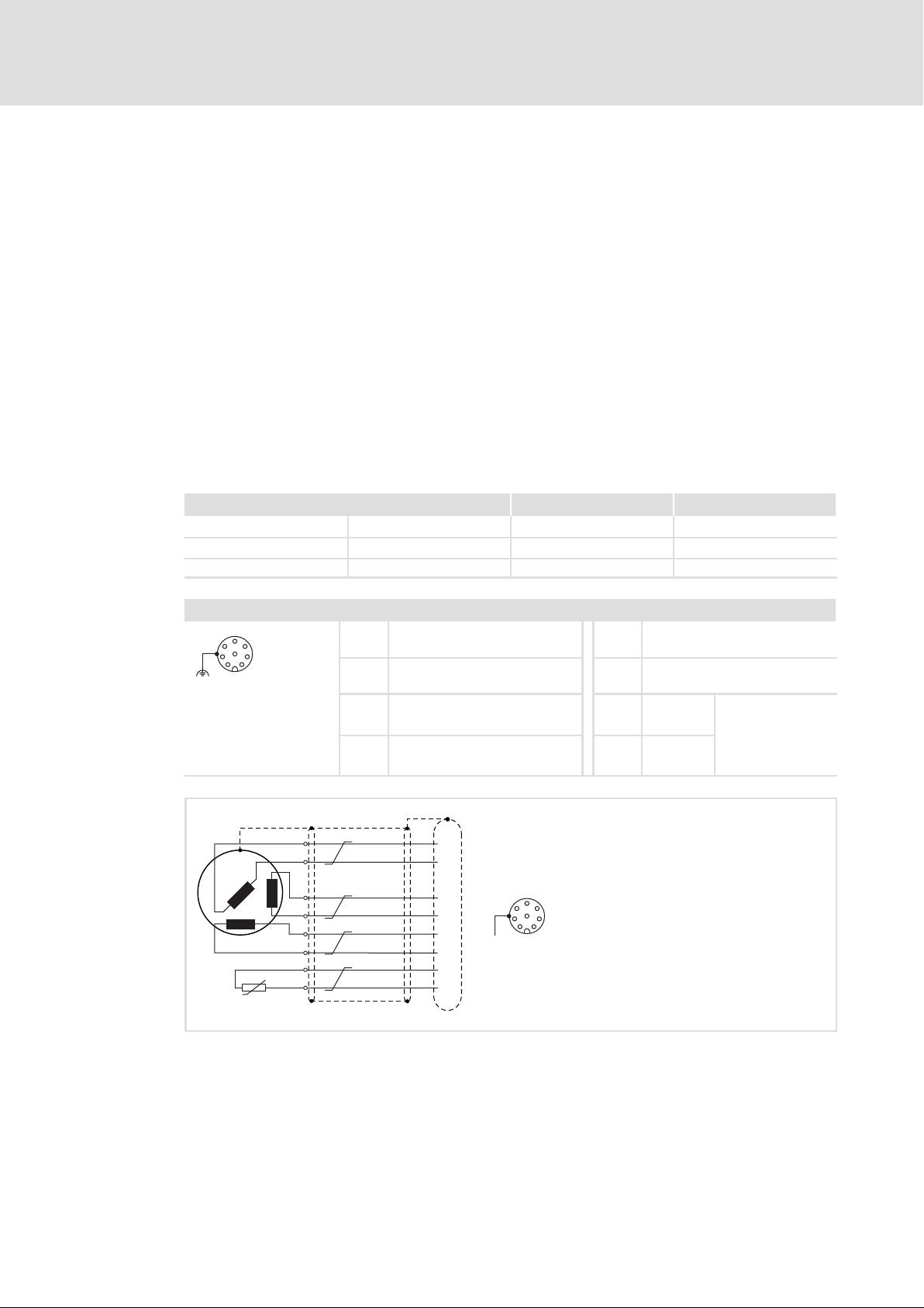
5.6.4 Feedback
X32 and X33 serve to connect feedback systems for servo control and sensors for motor
temperature monitoring.
ƒ Supported feedback system: resolver
ƒ Supported sensors for motor temperature monitoring: PT1000, KTY83/110,
KTY84/130, PTC acc. to DIN 44081, thermostat (normally−closed contact) acc. to
DIN 44080.
– Maximally three PTC thermistors may be connected in series.
– Monitored: short circuit and cable breakage. Thermostats are not monitored.
Each connection is assigned to a motor connection. The MOBILE DCU assignment is
configurable.
ƒ X32 <=> motor connection X12
ƒ X33 <=> motor connection X13
MOBILE DCU EMDxG2... l l
MOBILE PSU EMDxG3... ˘ ˘
MOBILE DCU/PSU EMDxG4... ˘ l
X32 X33
X32, X33 (M12 female socket A−coding)
5
6
4
3
8
7
1
2
EMDAG020d
1 +Ref
(+OSZ)
2 −Ref
(−OSZ)
3 +Sin 7 +KTY
4 −Sin 8 −KTY
+REF
-REF
+COS
-COS
+SIN
-SIN
KTY
+KTY
-KTY
X32 / X33
1
2
3
4
5
6
7
8
+
5 +COS
6 −COS
l KTY83/110
(+TEMP)
(−TEMP)
5
6
4
3
8
7
1
2
l KTY84/130
l PT1000
l PTC (DIN 44081)
l J−Switch NC
EMDAG035
56
Ò
EDSMDAG EN 2.0
Page 57
Installation
Connections of MOBILE DCU, PSU, DCU PSU
LV on−board supply system
5
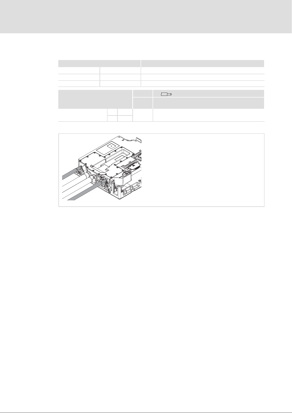
5.6.5 LV on−board supply system
X21
MOBILE DCU EMDxG2... ˘
MOBILE PSU EMDxG3... l
MOBILE DCU/PSU EMDxG4... l
X21+, X21−
+ M10
EMDAGxxxx
X21/B− must be connected to "chassis ground" (TRM31).
− M8
U
max
[V] [mm2]
[AWG]
32
70
000
with ring cable lug
EMDAG10_b
EDSMDAG EN 2.0
Ò
57
Page 58
5
Installation
Connections of MOBILE DCU, PSU, DCU PSU
Control system
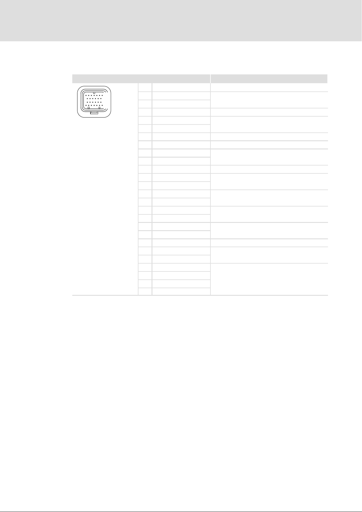
5.6.6 Control system
X31 Description
20
14
8
1
EMDAG020c
1 CAN_H_TERM_PUBLIC Public CAN, bus termination CAN−High
2 CAN_H_PUBLIC
3 CAN_L_PUBLIC
4 InterLock2 Potential−free output, connection 2
5 CAN_L_PRIVATE
6 CAN_H_PRIVATE
7 InterLock1 Potential−free output, connection 1
8 TRM15 Switch on/off device
9 CAN_H_PUBLIC
10 CAN_L_PUBLIC
11 CAN_L_TERM_PUBLIC Public CAN, bus termination CAN−Low
12 ID_PIN1
13 ID_PIN3
14 FLX_IN4
15 FLX_IN3
16 FLX_IN2
17 FLX_IN1
18 ID_PIN2
19 ID_PIN4
20 TRM31 Vehicle mass, negative pole of the vehicle battery
21 TRM30
22 TRM30
23 FLX_OUT4
24 FLX_OUT3
25 FLX_OUT2
26 FLX_OUT1
Public CAN In
Private CAN
Public CAN Out
Address offset for setting the CAN address
Digital inputs
l Can also be parameterised as frequency inputs
Digital inputs
l Can also be parameterised as analog inputs
Address offset for setting the CAN address
Supply voltage for control electronics
Digital outputs
58
Ò
EDSMDAG EN 2.0
Page 59

Installation
Connections of MOBILE DCU, PSU, DCU PSU
Addressing CAN bus nodes
5
5.6.7 Addressing CAN bus nodes
The MOBILE devices can be operated via the following CAN bus systems:
ƒ Public CAN: Communication with vehicle or subsystem control (e.g. air conditioning
system).
– The Public CAN is the customer interface provided for applications in commercial
vehicles which can be adapted to the respective communication and diagnostic
environments of the single OEM´s. By default, the control is carried out according
to SAE J1939 and the diagnostics is carried out according to UDS (Unified
Diagnostic Services) which is implemented in the Application Controller (AppC).
ƒ Private CAN: Communication with subsystem or other drives.
– The Application Controller (AppC) and the Motor Controller (MC) are connected via
the Private CAN (CAN2.0A) and communicate in accordance with CANopen, Drive
Profile DS 402. This Private CAN interface enables the Application Controller to
transmit the control commands received via the Public CAN to the Motor
Controller(s).
EDSMDAG EN 2.0
Ò
59
Page 60
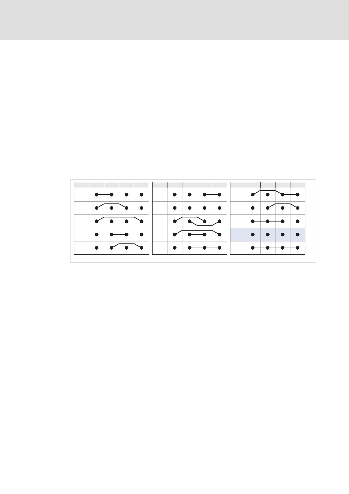
5
Installation
Connections of MOBILE DCU, PSU, DCU PSU
Addressing CAN bus nodes
Setting the address offset
Each MOBILE device has one address for the Public CAN and three addresses for the
Private CAN. An address consists of the basic address and the address offset (address =
basic address + address offset).
ƒ Lenze setting of the address offset: 13 (ID pins are not wired)
ƒ Lenze setting of the basic address for Public−CAN: 247
ƒ Lenze setting of the basic addresses Private−CAN:
– AppC: 45
– MC (channel 1): 14
– MC (channel 2): 77
The address offset is defined by wiring ID−Pin1...ID−Pin4 to X31. Thanks to the
combinations, 14 different address offsets are possible which means that up to 14 MOBILE
devices can be operated at a CAN bus.
ID-Pin1 ID-Pin2 ID-Pin3 ID-Pin4Offset
0
1
2
3
49
Fig. 5−1 Wiring at X31
ID−PIN1 X31/12
ID−PIN2 X31/18
ID−PIN3 X31/13
ID−PIN4 X31/19
Offset 13 Lenze setting
Boot Loader Startup Device remains in the Boot Loader, firmware is not started.
The length of the wire jumpers may be maximally 50 mm. If the ID pins are double assigned, the
contact must be double crimped.
ID-Pin1 ID-Pin2 ID-Pin3 ID-Pin4Offset
5
6
7
8
10
11
12
13
Boot-
Loader
Startup
ID-Pin1 ID-Pin2 ID-Pin3 ID-Pin4Offset
EMDAG033
60
Ò
EDSMDAG EN 2.0
Page 61
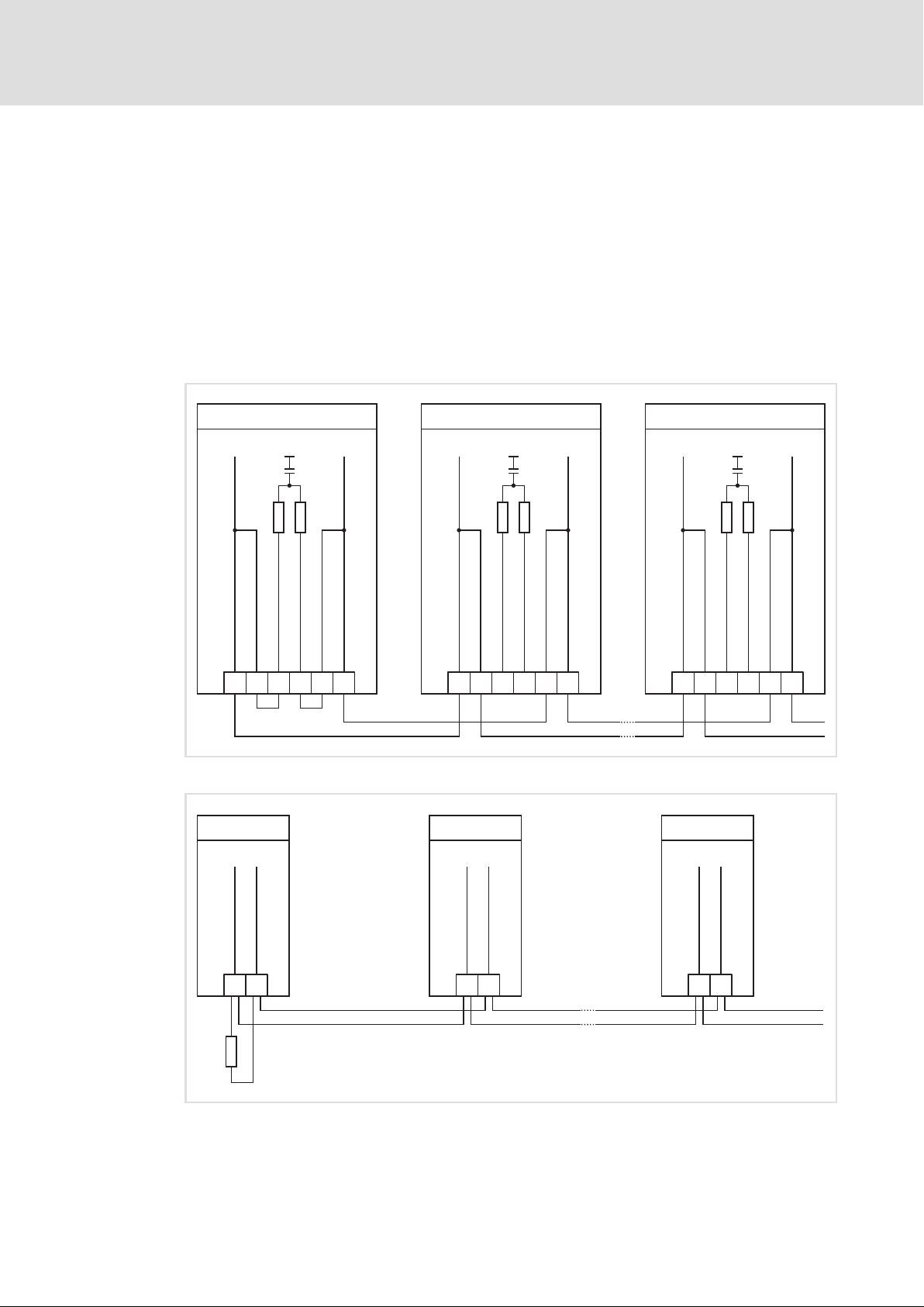
Connections of MOBILE DCU, PSU, DCU PSU
5.6.8 Activating the terminating resistor
In order to ensure a troublefree operation, a 120 W terminating resistor must be connected
to the last device of a CAN bus.
ƒ For Public CAN, the terminating resistor is integrated in each device. It is activated by
two bridges:
– Bridge between X31/1 (CAN_H_TERM_PUBLIC) and X31/2 (CAN_H_PUBLIC)
– Bridge between X31/11 (CAN_L_TERM_PUBLIC) and X31/10 (CAN_L_PUBLIC)
ƒ For Private CAN. no terminating resistor is integrated. The terminating resistor must
be connected externally.
Installation
Activating the terminating resistor
5
C
CAN_H_PUBLI
X31
EMDAG2 ... 4
Public CAN
60
60
C
C
C
CAN_H_PUBLI
CAN_L_TERM_PUBLI
CAN_H_TERM_PUBLI
12119
C
CAN_L_PUBLICCAN_L_PUBLI
103
C
CAN_H_PUBLI
X31
EMDAG2 ... 4
Public CAN
C
CAN_H_PUBLI
Fig. 5−2 Public CAN: activate terminating resistor
n = 1 + x n = 1
EMDAG2 ... 4
Private CAN
EMDAG2 ... 4
Private CAN
n = 1 + x
60
C
C
CAN_L_TERM_PUBLI
CAN_H_TERM_PUBLI
12119
60
C
CAN_L_PUBLICCAN_L_PUBLI
103
EMDAG2 ... 4
Public CAN
C
C
CAN_H_PUBLI
CAN_H_PUBLI
X31
EMDAG2 ... 4
Private CAN
n = 1
60
C
CAN_H_TERM_PUBLI
12119
60
C
CAN_L_TERM_PUBLI
CAN_L_PUBLICCAN_L_PUBLI
C
103
HCU
EMDAG044
EDSMDAG EN 2.0
ATE
CAN_L_PRIV
5
X31 6
120
ATE
CAN_H_PRIV
X31 6
ATE
ATE
CAN_H_PRIV
CAN_L_PRIV
5
Fig. 5−3 Private CAN: activate terminating resistor
Ò
ATE
CAN_L_PRIV
5
X31 6
ATE
CAN_H_PRIV
HCU
EMDAG050
61
Page 62
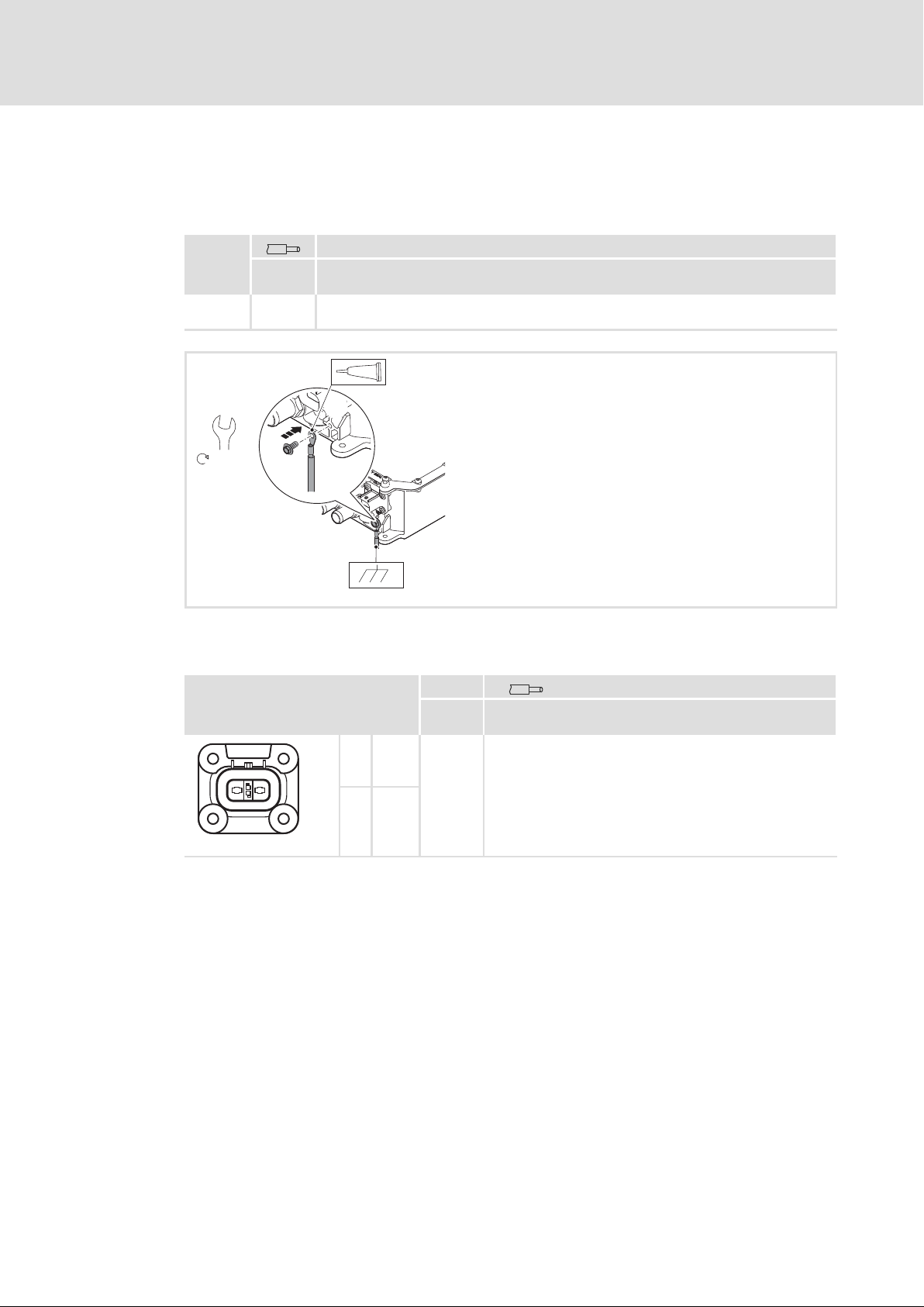
5
Installation
Connections of MOBILE DCU S
PE conductor
5.7 Connections of MOBILE DCU S
5.7.1 PE conductor
PE
[mm2]
[AWG]
+ 2.5 ... 4
12 ... 10
8 (Eco-Fix)
10
6.3 Nm
Connection with non−insulated ring cable lug, M6
xxxxx
DC4
xxxxxxxx
+
xxxxx
xxxxxxxx
5.7.2 HV on−board supply system
X2
1 +UG
21
EMDAG049b
2 −UG
V
max
[V DC] [mm2]
[AWG]
848
2.5 ... 4
12 ... 10
EMDAG029b
62
Ò
EDSMDAG EN 2.0
Page 63
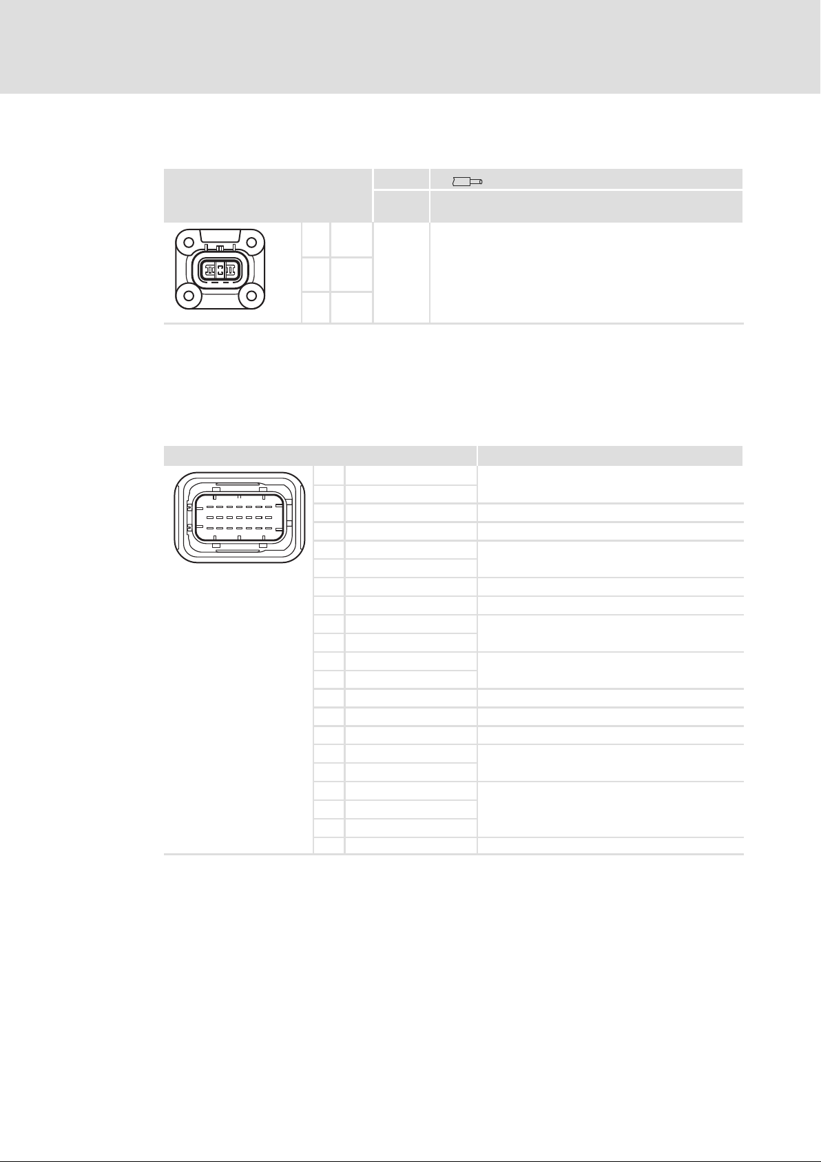
Installation
Connections of MOBILE DCU S
Motor
5
5.7.3 Motor
X3
3
1 2
ƒ In addition, a equipotential bonding between motor and DC/AC inverter is required.
ƒ Install the equipotential bonding conductor in parallel to the motor cable.
5.7.4 Control system
X1 Description
716
13 19
10
4
1
EMDAG049c
EMDAG049a
V
max
[V AC] [mm2]
[AWG]
1 U
2 V
3 W
1 CAN_H
2 CAN_L
3 CAN_L_TERM Bus terminating resistor for CAN
4 n.c. Do not use
5 TEMP_MA+
6 TEMP_MA−
7 TRM15 Switch on/off device
8 TRM30 Supply voltage for control electronics
9 CAN_H
10 CAN_L
11 FLX_IN4
12 FLX_IN3
13 n.c. Do not use
14 SWUP Secondary Wake up
15 TRM31 Vehicle mass, negative pole of the vehicle battery
16 FLX_IN1
17 FLX_IN2
18 ID_PIN1
19 ID_PIN2
20 ID_PIN3
21 n.c. Do not use
600
2.5
12
Public CAN and Private CAN network
Analog thermal sensor
Public CAN and Private CAN network
Digital inputs
Digital inputs
Address offset for setting the CAN address
EDSMDAG EN 2.0
Ò
63
Page 64

5
Installation
Connections of MOBILE DCU S
Addressing CAN bus nodes
5.7.5 Addressing CAN bus nodes
The MOBILE devices can be operated via the following CAN bus systems:
ƒ Public CAN: Communication with vehicle or subsystem control (e.g. air conditioning
system).
– The Public CAN is the customer interface provided for applications in commercial
vehicles which can be adapted to the respective communication and diagnostic
environments of the single OEM´s. By default, the control is carried out according
to SAE J1939 and the diagnostics is carried out according to UDS (Unified
Diagnostic Services) which is implemented in the Application Controller (AppC).
ƒ Private CAN: Communication with subsystem or other drives.
– The Application Controller (AppC) and the Motor Controller (MC) are connected via
the Private CAN (CAN2.0A) and communicate in accordance with CANopen, Drive
Profile DS 402. This Private CAN interface enables the Application Controller to
transmit the control commands received via the Public CAN to the Motor
Controller(s).
64
Ò
EDSMDAG EN 2.0
Page 65
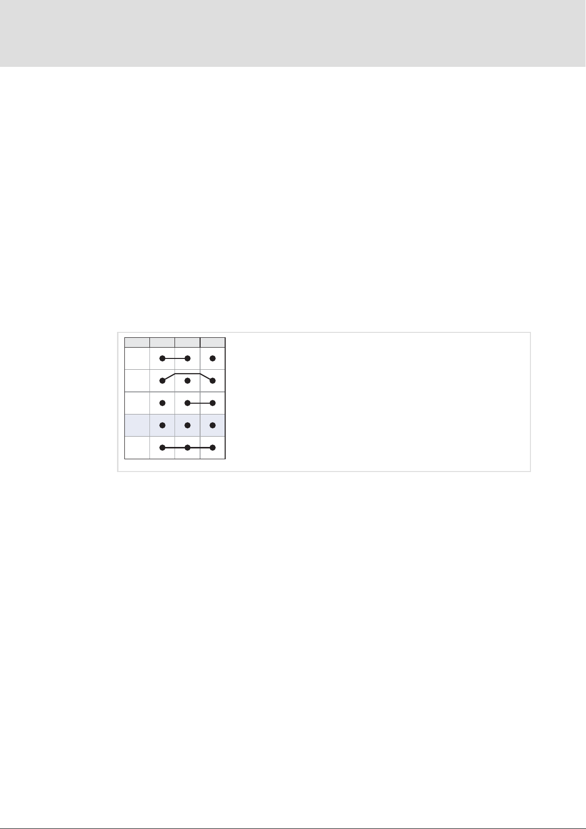
Installation
Connections of MOBILE DCU S
Addressing CAN bus nodes
Setting the address offset
Each MOBILE device has one address for the Public CAN and up to three addresses for the
Private CAN. An address consists of the basic address and the address offset (address =
basic address + address offset).
ƒ Lenze setting of the address offset: 13 (ID pins are not wired)
ƒ Lenze setting of the basic address for Public−CAN: 247
ƒ Lenze setting of the basic addresses Private−CAN:
– AppC: 45
– MC (channel 1): 14
– MC (channel 2): 77
Each device has one address for the Public CAN and three addresses for the Private CAN. An
address results from the addition of the basic address and the address offset (0...3).
The address offset is defined by wiring ID−Pin1...ID−Pin3 to X1. Thanks to the
combinations, 4 different address offsets are possible which means that up to 4 MOBILE
devices can be operated at a CAN bus.
5
ID-Pin1 ID-Pin2 ID-Pin3Offset
0
1
3
13
BootLoader
Startup
Fig. 5−4 Wiring at X1
ID−PIN1 X1/18
ID−PIN2 X1/19
ID−PIN3 X1/20
Offset 13 Lenze setting
Boot Loader Startup Device remains in the Boot Loader, firmware is not started.
The length of the wire jumpers may be maximally 50 mm. If the ID pins are double assigned, the
contact must be double crimped.
EMDAG031
EDSMDAG EN 2.0
Ò
65
Page 66
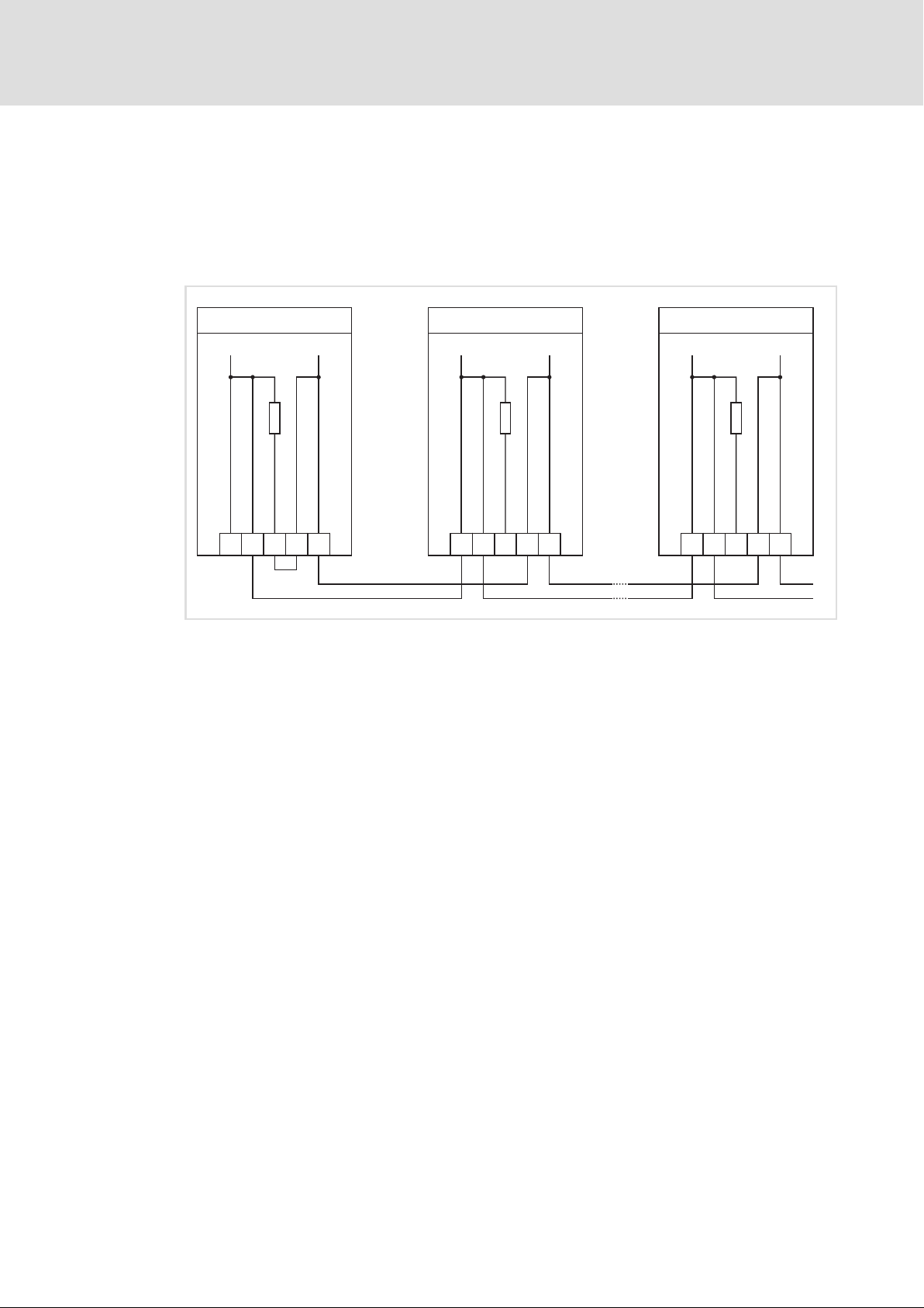
5
Installation
Connections of MOBILE DCU S
Activating the terminating resistor
5.7.6 Activating the terminating resistor
In order to ensure a trouble−free operation, a 120 W terminating resistor must be
connected to the last device of a CAN bus. The terminating resistor is integrated in each
device. It is activated by a bridge:
ƒ Bridge between X1/3 (CAN_L_TERM) and X1/9 (CAN_L)
EMDAG5...
CAN
n = 1 + x n = 1
EMDAG5...
EMDAG5...
CAN
CAN
120
CAN_H
CAN_L_TERM
CAN_H
913
X1
X1
10
CAN_L
CAN_L
2
Fig. 5−5 CAN: activate terminating resistor
120
CAN_H
CAN_L_TERM
CAN_L
CAN_L
2
CAN_H
91310
CAN_L
X1
120
CAN_H
CAN_L_TERM
CAN_L
2
CAN_H
91310
HCU
EMDAG039
66
Ò
EDSMDAG EN 2.0
Page 67

6 Commissioning
) Note!
ƒ Please observe the general safety instructions (¶ 10).
ƒ Please observe the notes regarding residual hazards (¶ 13).
The »MOBILE Engineer« tool supports you during the commissioning phase.
You are led through the commissioning steps and obtain additional information on the
settings. This information is also contained in the MOBILE reference manual which is
available in the download area.
Commissioning 6
EDSMDAG EN 2.0
Ò
67
Page 68
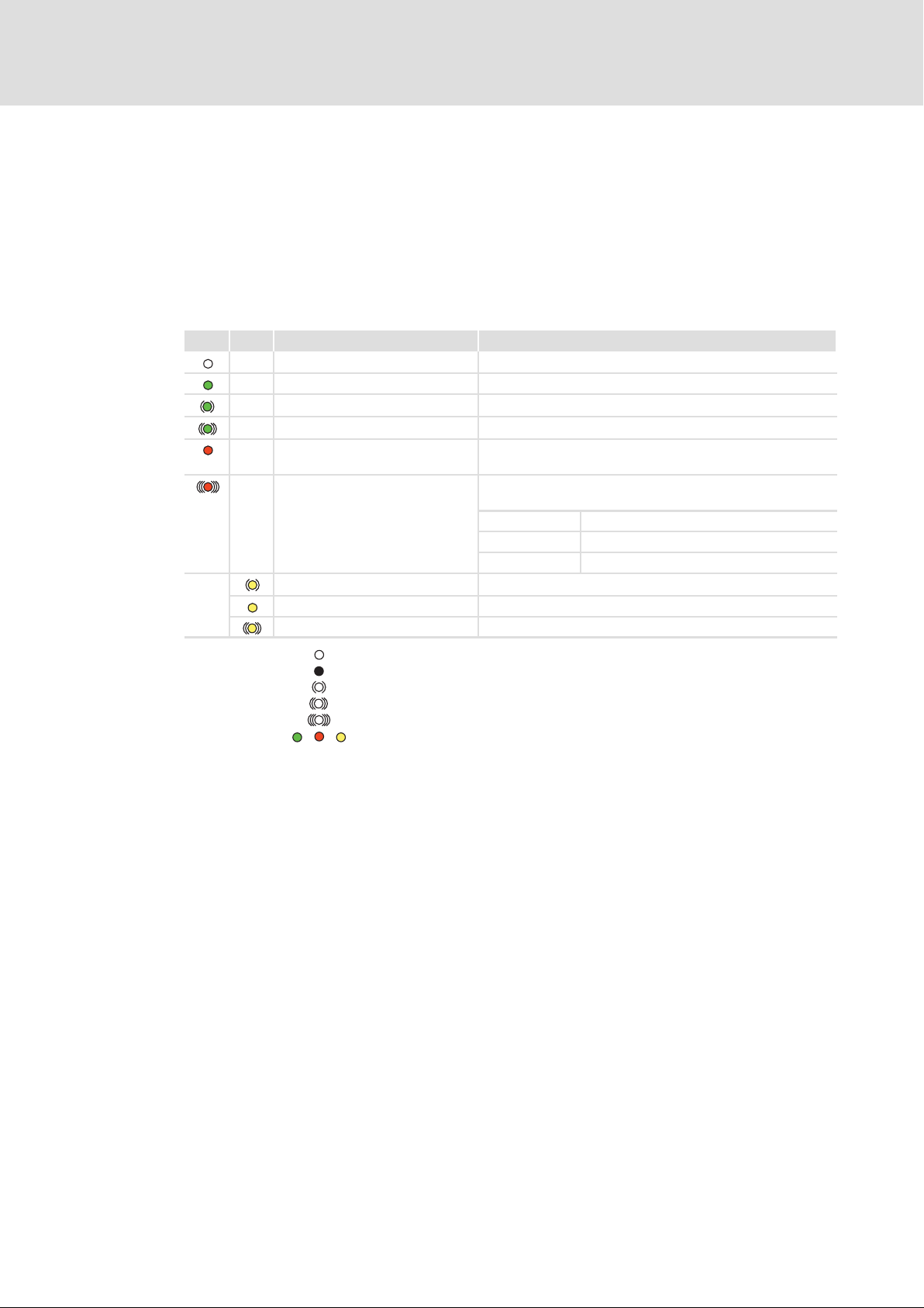
7
Diagnostics
Device status
MOBILE DCU, PSU, DCU PSU
7 Diagnostics
7.1 Device status
7.1.1 MOBILE DCU, PSU, DCU PSU
Two LEDs at the device display the current device status:
LED1 LED2 Device status Comments
Switched off ˘
Switched on − nor error No Public CAN messages are received.
Switched on − nor error Public CAN messages are received.
Switched on − boot loader active ˘
Switched on − error For a more detailed diagnosis, read the error memory or error
Switched on − error
Precharge / discharge active Blinking slowly
DC bus loaded VDC > 50 V
Cover not closed Blinking fast
code.
CAN communication is interrupted.
Diagnostics via CAN is not possible.
1× blinking: Invalid CAN address offset
4× blinking: Initialisation of the internal flash failed
5× blinking: Bootloader/firmware incompatibility
ƒ The device status can also be read via the CAN bus.
ƒ The Lenze »MobileEngineer« allows for a detailed diagnostics.
7.1.2 MOBILE DCU S
ƒ The device status can only be read via the CAN bus.
ƒ The Lenze »MobileEngineer« allows for a detailed diagnostics.
LED off
LED permanently on
LED blinking every 0.4 s
LED blinking every 0.2 s
LED blinking pattern: blinking once or several times with a break of 1 s
green − red − yellow
68
Ò
EDSMDAG EN 2.0
Page 69

8 Accessories (overview)
For a proper installation according to ECE R10, materials have to be processed
professionally complying with the respective standards and required approvals at the
location.
) Note!
Unused plug connections have to be sealed with covers or blanking plugs. This
is the only way to comply with the class of protection and prevent waterfrom
entering.
I Tip!
Spare parts can be obtained on request from the Lenze Expert Helpline at
www.lenze−schmidhauser.com
Accessories (overview) 8
EDSMDAG EN 2.0
Ò
69
Page 70

8
Accessories (overview)
Prefabricated cables and plug accessories
MOBILE DCU, PSU, DCU PSU
8.1 Prefabricated cables and plug accessories
8.1.1 MOBILE DCU, PSU, DCU PSU
Prefabricated cables and plug accessories serve to realise MOBILE installations quickly.
Function Name Type Use
HV on−board
supply system
Motor
Control plug Plug EMD accessory kit 26 pole cpl. for X31 EZAEVE028 MOBILE DCU
Resolver
Operation
without drive
High voltage cable EMD X11, 4 × 10 mm
Cable high voltage EMD X11, 4 × 6 mm2, 10 m EMDY901A0100E21A00
High−voltage cable EMD X11, 4 × 4 mm2, 10 m EMDY902A0100E31A00
High voltage cable EMD X11, 4 × 2.5 mm2, 10 m EMDY903A0100E41A00
Motor cable EMD X12, 4 × 10 mm2, 10 m, DCU EMDY900A0100E12A00 MOBILE DCU
Motor cable EMD X13, 4 × 10 mm2, 10 m, DCU EMDY900A0100E13A00 MOBILE DCU
Motor cable EMD X13, 4 × 10 mm2, 10 m, PSU EMDY900A0100E14A00 MOBILE DCU PSU
Motor cable EMD X12, 4 × 6 mm2, 10 m, DCU EMDY901A0100E22A00 MOBILE DCU
Motor cable EMD X13, 4 × 6 mm2, 10 m, DCU EMDY901A0100E23A00 MOBILE DCU
Motor cable EMD X13, 4 × 6 mm2, 10 m, PSU EMDY901A0100E24A00 MOBILE DCU/PSU
Motor cable EMD X12, 4 × 4 mm2, 10 m, DCU EMDY902A0100E32A00 MOBILE DCU
Motor cable EMD X13, 4 × 4 mm2, 10 m, DCU EMDY902A0100E33A00 MOBILE DCU
Motor cable EMD X13, 4 × 4 mm2, 10 m, PSU EMDY902A0100E34A00 MOBILE DCU PSU
Motor cable EMD X12, 4 × 2.5 mm2, 10 m, DCU EMDY903A0100E42A00 MOBILE DCU
Motor cable EMD X13, 4 × 2.5mm2, 10 m, DCU EMDY903A0100E43A00 MOBILE DCU
Motor cable EMD X13, 4 × 2.5mm2, 10 m, PSU EMDY903A0100E44A00 MOBILE DCU PSU
Resolver cable Mobile X32, X33, 1.5m EMDY700F0015B03A01
Resolver cable Mobile X32, X33, 3.0m EMDY700F0030B03A01
Resolver cable Mobile X32, X33, 5.0m EMDY700F0050B03A01
Resolver cable Mobile X32, X33, 10m EMDY700F0100B03A01
Power connector cover for X12, X13 EZAMSK002
2
, 10 m EMDY900A0100E11A00
MOBILE DCU
MOBILE PSU
MOBILE DCU PSU
MOBILE PSU
MOBILE DCU PSU
MOBILE DCU
MOBILE DCU PSU
70
Other cable lengths on request.
Ò
EDSMDAG EN 2.0
Page 71
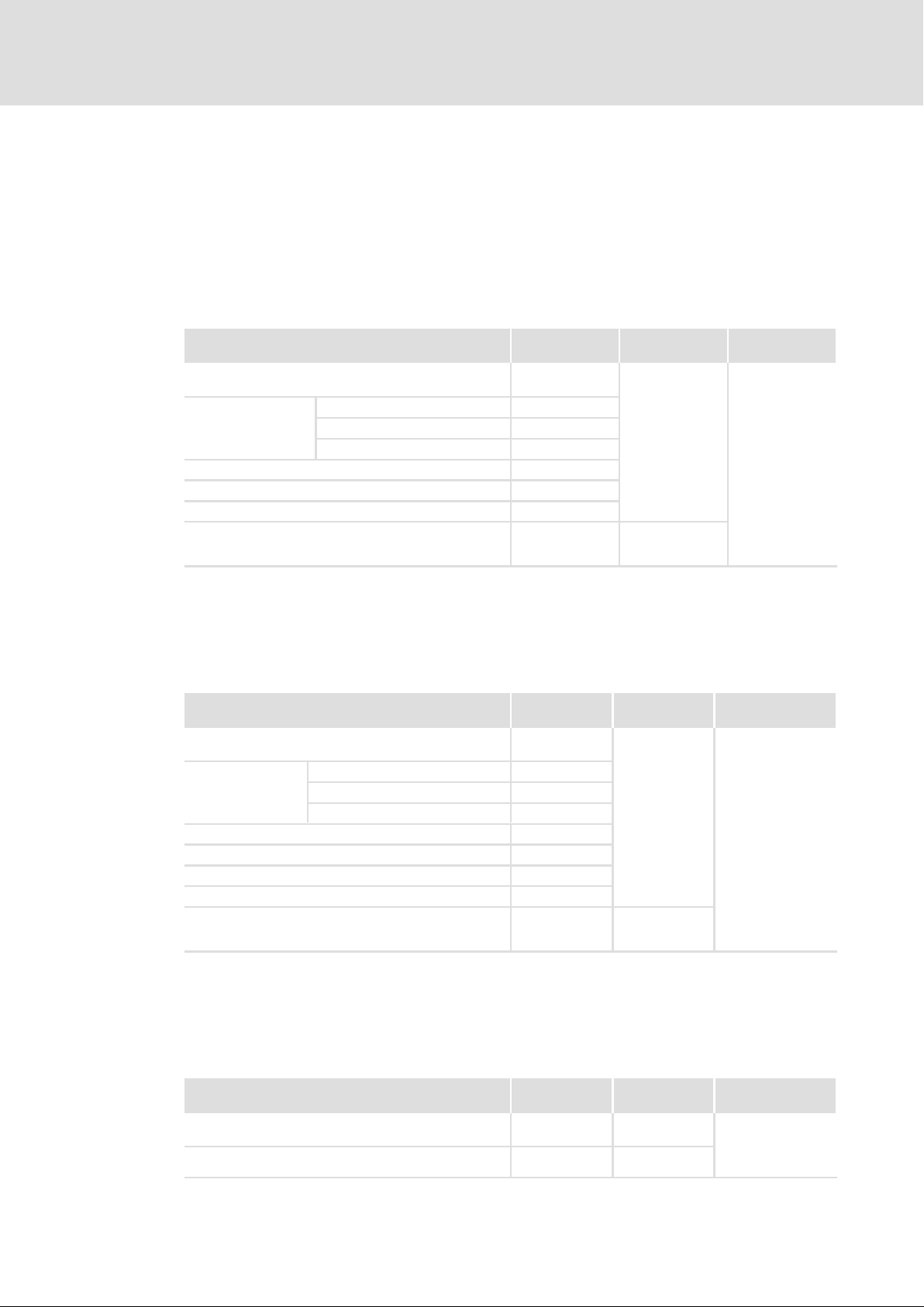
Accessories (overview)
Individual parts for the electrical installation
MOBILE DCU, PSU, DCU PSU
8
8.2 Individual parts for the electrical installation
8.2.1 MOBILE DCU, PSU, DCU PSU
Here, the required material for plugs, plug parts and cables are listed and assigned to
terminals.
HV on−board supply system at X11
Name
Additional information
7−pole receptacle housing
1× per X11
Flat connector
4× per X11
Single conductor seal, orange (2.5 ... 6 mm2) 108 004 727 42
Single conductor seal, black (10 ... 12 mm2) 108 004 727 43
Blanking plug, green 108 004 726 31
Radox® 155
Cable with vehicle−specific properties
typical cross−section: 4 × 10 mm
8 ... 12 mm2 6.3 × 0.8 LSK8 ELA 231 245 444 20
4 ... 6 mm2 6.3 × 0.8 LSK8 ELA 231 244 726 20
2.5 ... 4 mm2 6.3 × 0.8 LSK8 ELA 231 244 922 00
2
, shielded, Ø ~ 17.2 mm
Tightness according to manufacturer information:
Type Manufacturer Use
094 401 94
841 370 53 Huber & Suhner
Kostal MOBILE DCU
MOBILE PSU
MOBILE DCU PSU
ƒ Use 4× orange or black single conductor seals and 3× green blanking plugs per
receptacle housing.
Motor at X12, X13
Name
Additional information
7−pole receptacle housing
1× per X12 or X13
Flat connector
3× per X12 or X13
Single conductor seal, orange (2.5 ... 6 mm2) 108 004 727 42
Single conductor seal, black (10 ... 12 mm2) 108 004 727 43
Blanking plug, green 108 004 726 31
Blanking plug, yellow 108 004 726 39
Radox® 155
Cable with vehicle−specific properties
typical cross−section: 4 × 10 mm
8 ... 12 mm2 6.3 × 0.8 LSK8 ELA 231 245 444 20
4 ... 6 mm2 6.3 × 0.8 LSK8 ELA 231 244 726 20
2.5 ... 4 mm2 6.3 × 0.8 LSK8 ELA 231 244 922 00
2
, shielded, Ø ~ 17.2 mm
Type Manufacturer Use
094 401 94
841 370 53 Huber & Suhner
Kostal MOBILE DCU
MOBILE DCU PSU
Tightness according to manufacturer information:
ƒ Use 3× orange or black single conductor seals and 3× green blanking plugs and 1×
yellow blanking plugs.
LV on−board supply system at X21/B+, X21/B−
EDSMDAG EN 2.0
Name
Additional information
Ring cable lug M10 for 70 mm2, 90° angled
1× per X21 B+
Ring cable lug M8 for 70 mm2, 90° angled
1× per X21 B−
Ò
Type Manufacturer Use
˘ ˘
˘ ˘
MOBILE DCU PSU
MOBILE PSU
71
Page 72
8
Accessories (overview)
Individual parts for the electrical installation
MOBILE DCU S
Control at X31
Name Type Manufacturer Use
Socket housing Superseal 1.0, 26−pole 3−1437290−7
Crimp socket
Sealing plug 4−1437284−3
Strands suitable for
vehicles
CAN cable acc. to ISO 11898−2 ˘ ˘
0.75 ... 1.25 mm
0.5 mm
0.3 mm
0.3 ... 1.25 mm
2
2
2
2
3−1447221−3
3−1447221−4
3−1447221−5
3−1437290−7
TE Connectivity MOBILE DCU
MOBILE PSU
MOBILE DCU PSU
Tightness according to manufacturer information:
ƒ Use a strand diameter of 1.6 ... 2.2 mm.
Feedback at X32, X33
Name Type Manufacturer Use
M12 connector with prefabricated cable, 8 × 0.25 mm
(AWG24), shielded
A coded, 90° angled
2
M12 e.g.
Phoenix Contact
MOBILE DCU
MOBILE DCU PSU
8.2.2 MOBILE DCU S
Here, the required material for plugs, plug parts and cables are listed and assigned to
terminals.
Control at X1
Name Type Manufacturer
Socket housing Leavyseal
AMP MCP 2.8 SOCKET HSG.,21POS.ASSY code A
COVER F.21P REC−HSG black 9−1394050−1
2,8 blanking plug transparent 828922−1
2,8 single conductor seal 1.4...2.1mm blue 828904−1
2,8 single conductor seal 2.2...3.0mm white 828905−1
AMP MCP 2.8, CONTACT SWS 2mm−goldplated 0.5...1.0mm
AMP MCP 2.8, CONTACT SWS 1...3mm−tinplated 0.5...1.0mm
AMP MCP 2.8, CONTACT SWS 3...5mm−silverplated 0.5...1.0mm
AMP MCP 2.8, CONTACT SWS 2mm−goldplated 1.5...2.5mm
AMP MCP 2.8, CONTACT SWS 1...3mm−tinplated 0.5...1.0mm
AMP MCP 2.8, CONTACT SWS 3...5mm−silverplated 0.5...1.0mm
black/yellow 3−1437290−7
2
1−968855−2
2
1−968855−1
2
1−968855−3
2
1−968857−2
2
1−968857−1
2
1−968857−3
TE Connectivity
72
Ò
EDSMDAG EN 2.0
Page 73
Individual parts for the electrical installation
HV on−board supply system at X2
Accessories (overview)
MOBILE DCU S
8
Name
HVA280 cable 2 × 4mm
A coded
HVA280−2PHM
Individual parts
Plug Sub−Assy Code A 1× per X2 4−2103015−1
Collet Size 1 1× per X2 2103155−1
Seal Retainer Size 1 1× per X2 2103013−1
Seal Cable Size 1 1× per X2 2103154−1
Outer Ferrule Size C 1× per X2 1587724−3
Plug Shield Size 1 2× per X2 1−2103157−1
Spacer 1× per X2 2103153−1
Inner Ferrule Size C 1× per X2 1587723−3
Inner Housing 1× per X2 1587985−1
AMP MCP 2.8K Contact 4mm
silverplated
Power Cable 2 × 4mm
Motor at X3
Type Manufacturer
2
2
500 mm
1000 mm 1−2208103−1
2000 mm 1−2208103−2
3000 mm 1−2208103−3
4000 mm 1−2208103−4
5000 mm 1−2208103−5
6000 mm 1−2208103−6
2× per X2 1−968853−3
2
1−2208103−0
2177114−1
TE Connectivity
Name
HVA280 cable 3 × 2.5mm
B−coded
HVA280−3PXM
Individual parts
Plug Sub−Assy Code B 1× per X2 4−2103015−2
Collet Size 2 1× per X2 2103155−2
Seal Retainer Size 2 1× per X2 2103013−3
Seal Cable Size 2 1× per X2 2103154−2
Outer Ferrule Size B 1× per X2 1587724−2
Plug Shield Size 2 2× per X2 1−2103157−2
Spacer 1× per X2 2103153−1
Inner Ferrule Size B 1× per X2 1587723−2
Inner Housing 1× per X2 2103306−1
AMP MCP 2.8K Contact
1.0...2.5mm
Power Cable 3 × 2.5mm
2
2
silverplated
Type Manufacturer
2
2−2177626−0
2177877−1
500 mm
4000 mm 2−2177626−4
3× per X2 1241390−3
TE Connectivity
EDSMDAG EN 2.0
Ò
73
Page 74

Index9
9 Index
A
Accessories, 69
Application as directed, 11
C
Cable
− For control connections, 47
− for the HV on−board connection, 45
− for the motor connection, 46
Commissioning, 67
Connection
− HV on−board supply system, 54, 62
− on−board supply system, 57
Control cable, 47
D
DC−bus operation, 23
Definition of notes used, 9
Definitions, Terms, 7
Device protection, 13, 40
Diagnostics, 68
Digital inputs, 31, 34
Digital outputs, 32
Disposal, 12
E
Electrical installation, 48
EMC, what to do in case of interferences, 47
F
For your personal safety, 10
H
HV on−board cable, 45
Interferences, eliminating EMC interferences, 47
M
Maintenance and servicing, 12
Mechanical installation, 41
Motor cable, 46
− capacitance per unit length, 24
− requirements, 24
Motor protection, 13
Mounting clearances, 23
Mounting position, 23
N
Nameplate, 20
Notes, definition, 9
O
Overspeeds, 13
Overview, Accessories, 69
P
Product description, 14
Protection of persons, 13
R
Requirements, motor cable, 24
Residual hazards, 13
S
Safety instructions, 10
− basic, 10
− definition, 9
− layout, 9
Supply conditions, 23
I
Identification, 20
Installation, 39
− electrical, 48
− mechanical, 41
− water cooling, 36, 43
74
T
Technical data, 22
Terms, definitions, 7
Thermal sensor, input, 35
Transport, storage, 11
Type code, finding, 20
Ò
EDSMDAG EN 2.0
Page 75

V
Validity, 5
Voltage supply, 31, 34
W
Water cooling, installation, 36, 43
Index 9
EDSMDAG EN 2.0
Ò
75
Page 76

F
© 04/2018
Lenze Schmidhauser
Obere Neustrasse 1
CH−8590 Romanshorn
Switzerland
ß
Service Lenze Service GmbH
Breslauer Straße 3
D−32699 Extertal
Germany
(
Ê
ü
+4171 46611−11
+4171 46611−10
Info@Lenze−Schmidhauser.ch
www.Lenze.com
(
Ê
0080002446877 (24 h helpline)
+49515482−1112
EDSMDAG § .Rtù § EN § 2.0 § TD29
10987654321
 Loading...