

Page 1
BA 12.0031
Show/Hide Bookmarks
.ð&Q
Ä."&Qä
Operating Instructions
G-motion
R
Integrated ATEX motors - 3D category
Page 2
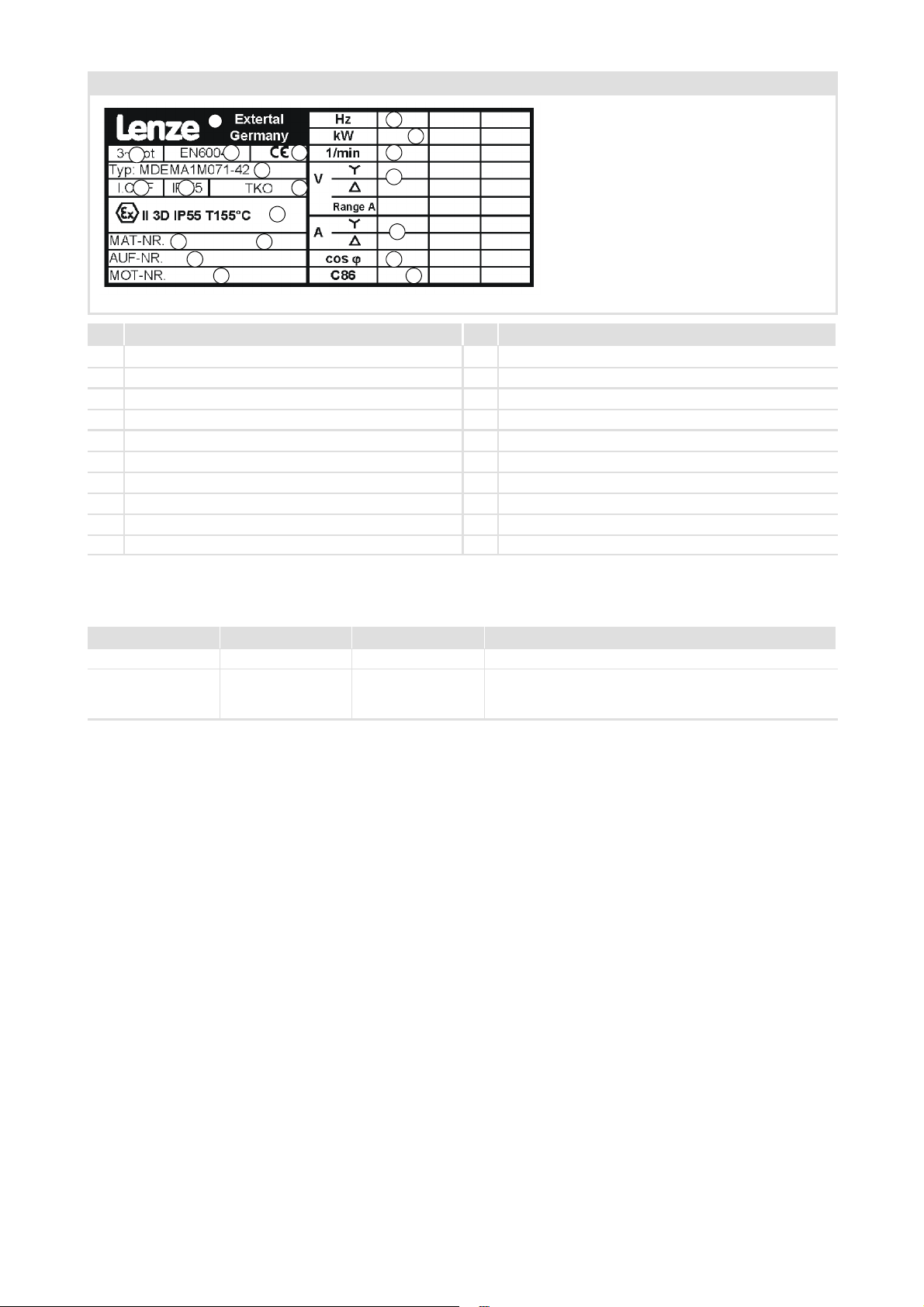
Motor nameplate
Show/Hide Bookmarks
Example / contents
1
2
6 7 8
10
3 4
5
9
11
12
13
14
15
16
17
18
19
20
No. Explanation No. Explanation
1 Manufacturer / assembly plant 11 Manufacturing date
2 Three-phase AC motor 12 Order no.
3 EN standard 13 Motor no.
4 CE designation 14 Rated frequency
5 Motor type 15 Rated power
6 Thermal class 16 Rated speed
7 Enclosure 17 Rated voltage
8 Thermal protection 18 Rated current
9 Explosion protection specification 19 Rated power factor cos ϕ
10 Material number 20 C86 code
What is new / what has changed in the Operating Instructions?
Material number Edition Important Contents
130 099 69 1.0 08/04 TD09 1st edition First edition
130 105 48 2.1 11/04 TD09 1st edition Added danger note for the characteristic for self-ventilation.
Changed table in Ch. 4.2 and added footnotes.
Declaration of Conformity: changed type designation.
© 2004
Lenze Drive Systems GmbH,Hans-Lenze-Straße 1,31855 Aerzen
No part of this documentation may be reproduced or made accessible to third parties without written consent by
Systems GmbH
.
All information given in this documentation has been selected carefully and complies with the hardware and software described.
Nevertheless, deviations cannot be ruled out. We do not take any responsibility or liability for damages which might possibly occur.
Necessary corrections will be included in subsequent editions.
2
Lenze Drive
BA 12.0031 EN 2.1
Page 3

Contents i
Show/Hide Bookmarks
1 Safety instructions 4.........................................................
1.1 Application as directed 4................................................
1.2 Definition of notes used 5...............................................
2 Mechanical installation 6.....................................................
2.1 Preparation 6..................................................
2.2 Installation / mounting condition 6.......................................
3 Electrical installation 7.......................................................
4 Maintenance 12.............................................................
4.1 Maintenance intervals 12................................................
4.1.1 Periodic inspections 12...........................................
4.2 Maintenance and repair 13...............................................
5 Appendix 14................................................................
5.1 EC Declaration of Conformity 14..........................................
BA 12.0031 EN 2.1
3
Page 4

1
Show/Hide Bookmarks
Safety instructions
Application as directed
1 Safety instructions
ƒ These Operating Instructions are valid only in conjunction with the general
Operating Instructions for MDXM three-phase AC motors! It represents an
addendum and is amended with aspects concerning explosion protection. In
addition, please observe the safety instructions for gearboxes in the ATEX gearboxes
Operating Instructions.
ƒ If the data are inconsistent, these Operating Instructions have priority.
ƒ Pay attention to an installation according to EMC, especially for frequency inverter
operation!
If these Operating Instructions are disregarded, especially the inspection and
maintenance intervals, the EC declaration of conformity will become void.
1.1 Application as directed
The motors described in these operating instru ctions are designed specifically for direct
mounting on Lenze gearboxes of the G-motion series. In this design, the interface
between motor and gearbox can no longer be separated since components of the motor
become components of the g earbox and vice versa. Among other things, these
components also handle functions that ensure safe operation with respect to explosion
protection. For example, the shaft sealing ring of the motor handles the sealing of the
gearbox.For this reason, the subsequent text also refers to the geared motor since the
safety aspects listed here do not apply only to the motor and a separate operation of the
(without gearbox) would not make any sense.
The geared motors are intended for use in machinery and systems and may only be
used in accordance with these operating instructions, the nameplate and the text of the
order confirmation. They correspond to existing standards and regulations and meet
the requirements of EU directive 94/9/EG.
Explosive gas, fog, vapour, or dust atmospheres can cause severe injuries or death when
getting in contact with hot and / or sparking parts of the geared motor.
All operations concerning mounting, connection, commissioning as well as
maintenance and repairs on the geared motor and the electrical supplementary
equipment must only be carried out by qualified personnel!
ƒ During installation, EN 50281-1-2 in potentially explosive (dust) atmospheres must
be observed!
4
The machines can be used as follows:
A In zone 22 (dust Ex, category 3D) with non-conductive dusts with a minimum
ignition power > 3mJ.
BA 12.0031 EN 2.1
Page 5

1.2 Definition of notes used
Show/Hide Bookmarks
The following signal words and symbols are used in this documentation to indicate
dangers and important information:
Safety instructions
Structure of safety instructions:
Safety instructions
Definition of notes used
1
Pictograph and signal word Meaning
Application notes
Pictograph and signal word Meaning
Danger!
(characterises the type and severity of danger)
Note
(describes the danger and gives information about how to prevent dangerous
situations)
Danger of personal injury through dangerous electrical
voltage.
Danger!
Danger!
Stop!
Note!
Reference to an imminent danger that may result in death or
serious personal injury if the corresponding measures are not
taken.
Danger of personal injury through a general source of danger
Reference to an imminent danger that may result in death or
serious personal injury if the corresponding measures are not
taken.
Danger of property damage.
Reference to a possible danger that may result in property
damage if the corresponding measures are not taken.
Important note to ensure trouble-free operation
X
H
BA 12.0031 EN 2.1
Tip!
Useful tip for simple handling
Reference to another documentation
5
Page 6

2
Show/Hide Bookmarks
Mechanical installation
Installation / mounting condition
Preparation
2 Mechanical installation
2.1 Preparation
ƒ It must be checked that the data given on the nameplate of the motor and in the
order confirmation text comply with the permissible explosion-proof application
conditions on site:
–Exgroup
–Excategory
–Zone
– Maximum surface temperature
ƒ The use of the geared motor is only permissible at an ambient temperature of -20 °C
to +40 °C unless the nameplate bears another temperature.
2.2 Installation / mounting condition
Danger!
ƒ
Parts of the geared motor consist of aluminium and must be protected
against external shocks in order to prevent shock sparks.
ƒ
The geared motors must
ƒ
The geared motors must be included in the equipotential bonding of the
system.
ƒ
The installation of the geared motors must be carried out in such a way that
a sufficient dissipation of heat loss is ensured and the fan of the motor can
supply the cooling air required for safe operation.
not
be used in systems with cathodic protection!
6
BA 12.0031 EN 2.1
Page 7

3 Electrical installation
Show/Hide Bookmarks
Electrical installation 3
Power supply connection
The motor is connected to the motor terminal board in the following structure accor ding
to theterminal connection diagram affixed insidethe terminal box. Ensurethat the screw
connections are secure.
7
6
5
4
3
2
1
Fig. 1 Terminal stud of motor terminal board
Danger!
The safety instructions in Chapter 1 must be observed!
1 Windingconnection
2 Hexagon nut
3Washer
4 Motor connection cable lug / power supply
5Washer
6 Hexagon nut
7 Terminal board stud
BA 12.0031 EN 2.1
7
Page 8

Electrical installation3
Show/Hide Bookmarks
PE conductor connection
At the PE conductor connection in the terminal box and on the housing of the motor, the
PE conductormust be connected byplacing a plainwasher between cablelug and housing
of the motor. A serrated lock washer between cable lug and screw head / hexagon nut
ensures an electrically well-conductive connection. The following illustrations show the
correct connection for the different designs of the PE conductor connections:
4
3
2
1
Fig. 2 Earth connection at housing and in terminal box
1Washer
2 Earth connection cable lug
3 Serrated lock washer
4Screw
56
4
3
2
1
Fig. 3 Earth connection via terminal stud in terminal box
1Terminalstud
2Earthsymbol
3Washer
4 Earth connection cable lug
5 Serrated lock washer
6 Hexagon nut
Selection of cable gland
8
Thethreaded holes ofthe terminalbox areclosed usinghigh-quality screwplugs withseal.
To insert the supply conductor in the terminal box, the corresponding screw plug is
replaced bya cable glandwith strain relief.For this purpose,it is necessary toselect a cable
gland that is certified for explosion protection and features at least enclosure IP54.
BA 12.0031 EN 2.1
Page 9

Electrical installation 3
q
y
Show/Hide Bookmarks
Protection against impermissible high temperatures
Under normal operating conditions, the motors ensure safe operation within the
explosion protection specification listed on the nameplate. To protect the motor against
impermissible high temperatures in case of an overload, the thermal contact embedded
in the motor winding must be analysed by a device that is suitable for this purpose. If the
thermal contact is tripped, all phases of the motor must be disconnected from mains.
Danger!
Before commissioning, the effectiveness of the protective device must be
checked.
Frequency inverter operation
Motors of category 3D in the combination listed below can be operated with the Lenze
frequency inverter.
Motor frame size
063 - 12 0.12 ---
063 - 32 0.18 ---
063 - 42 0.25 E82EV251
071 - 32 0.37 E82EV371
071 - 42 0.55 E82EV551
080 - 32 0.75 E82EV751
080 - 42 1.1
090 - 32 1.5
100 - 12 2.2 E82EV222
100 - 32 3.0 E82EV302
112 - 22 4.0 E82EV402
112 - 32 5.5 E82EV552
132 - 22 7.5 E82EV752
132 - 32 9.2 E82EV113
Tab. 1 Motor - frequency inverter assignment 50 Hz
P
N
[kW] [Hz]
f
50
N
Frequency inverter
E82EV152
E82EV152
BA 12.0031 EN 2.1
9
Page 10

Electrical installation3
q
y
Show/Hide Bookmarks
Motor frame size
063 - 12 0.21 E82EV251
063 - 32 0.33 E82EV371
063 - 42 0.45 E82EV551
071 - 32 0.66 E82EV751
071 - 42 1.00 E82EV152
080 - 32 1.35 E82EV152
080 - 42 2.0
090 - 32 2.7
100 - 12 3.9 E82EV402
100 - 32 5.4 E82EV552
112 - 22 7.1 E82EV752
112 - 32 9.7 E82EV113
132 - 22 13.2 E82EV153
132 - 32 16.2 E82EV223
Tab. 2 Motor - frequency inverter assignment 87 Hz
Danger!
P
N
[kW] [Hz]
During operation, special attention should be paid that the maximum
permissible speeds for the gearbox are not exceeded.
f
87
N
Frequency inverter
E82EV222
E82EV302
Analogous to mainsoper ation, operating the motor with frequency inverter mayresult in
impermissible high surface temperatures in case of overload or at low operating
frequencies. Forthis reason, thefrequency inverteroperation is onlypermissible usingthe
analysis of the thermal contact via a suitable instrument.
Danger!
Before commissioning, the effectiveness of the protective device must be
checked.
10
BA 12.0031 EN 2.1
Page 11

Electrical installation 3
Show/Hide Bookmarks
Motor frame size-dependent torque reduction with self-ventilation and operation with
frequency inverter
Danger!
If the characteristics indicated in the following diagram are used with
self-ventilation, only S2 - 10-min - operation is permissible below 20 Hz.
Motor frame size
Output frequency of frequency inverter
Fig. 4 Torque reduction with frequency inverter operation
The use of a separate fan allowsfor operation without restrictions concerning torque and
duty cycle.
BA 12.0031 EN 2.1
11
Page 12

4
Show/Hide Bookmarks
Maintenance
Maintenance intervals
Periodic inspections
4 Maintenance
4.1 Maintenance intervals
Based on EN 60079-17, the following terms are used in this chapter:
Visual inspection
Inspection which identifies, without the use of access equipment or tools, those defects,
such as missing bolts, which will be apparent to the eye.
Close inspection
Inspection which encompasses those aspects covered by a visual inspection and, in
addition, identifies those defects, such as loose bolts, which will be apparent only by the
use of access equipment, for example steps, and tools.
Danger!
If there are unusual operating noises, vibrations, or increased temperatures in
the geared motor during or between the prescribed checks, the geared motor
must be immediately put out of operation and maintenance must be
performed!
On principle, the requirements from the applicable regulations and standards,
such regulations from professional trade ass ociations (BGV A2), operating
regulations (EN 50110) and installation regulations (EN 60079-17) must be
observed!
Plastic parts must be damp-cleaned only to prevent electrostatic charge.
Maintenance and repair
Combination of any actions carried out to retain an item (here: the motor) in, or restore it
to conditions in whichit is able to meet therequirements of therelevant specificationand
perform its required functions.
4.1.1 Periodic inspections
Gearedmotors withdirect motormounting(without standard cup)are also equippedwith
oil-sight glass or oil-level check plug in category 3. This is to provide a means of checking
for oil loss in the gearbox if oil enters the motor unnoticed through leakage at the shaft
sealing ring of the motor.
For the mounting positions A, B, C, E and F, the time intervals listed below can be doubled.
12
BA 12.0031 EN 2.1
Page 13

Maintenance
Show/Hide Bookmarks
Maintenance intervals
Maintenance and repair
Types of inspection
Visual Close
Inspection to be made in the time interval of operating hours: --- 500 h
Not later than after: 1month 3months
Actions
Visual inspection of the geared motor.
Dust accumulation should be cleaned depending on the amount of dust collected. It is
recommended to remove dust accumulations of 1 mm thickness and more on the
housing and in the cooling ribs.
Check for oil entering the motor by checking the oil level in the gearbox acc. to Ch. 4.3
of the ATEX gearboxes operating instructions.
4.2 Maintenance and repair
Maintenance/repair to be made in the time interval of operating hours: 1) 2)
Not later than after: 5years ---
Actions
Replace shaft sealing rings of motor.
Check condition of sealing lip contact area, repair if necessary.
Replace roller bearing grease
Replace roller bearings of the motors.
1) Conforming with the gearbox: Determining the time frame for measuring the oil temperature according to Chapter
4.5 and oil change diagram according to Chapter 5.2 of the ATEX gearbox operating instructions.
2) Conforming with the gearbox: Determining the time frame according to roller bearing main tenance diagram
according to Chapter 5.2.2 of the ATEX gearbox operating instructions.
•
•
Types of inspection
Maintenance/repair
•
•
4
Danger!
The repair work of explosion-protected electrical machines must only be
performed by the manufacturer or skilled personnel qualified for these tasks in
a workshop equipped for these tasks. Use only the respective original spare
parts from Lenze. The operating steps must be performed in accordance with
the instructions from the manufacturer.
Equipment which has been changed or repaired at parts that guarantee the explosion
protection, must only be started again if an expert has confirmed the conformance with
the valid technical regulations.
BA 12.0031 EN 2.1
13
Page 14

5
Show/Hide Bookmarks
Appendix
EC Declaration of Conformity
5 Appendix
5.1 EC Declaration of Conformity
EC Declaration of Conformity
For the purpose of t he EC Directive ”Equipment and protective systems
intended for use in potentiallyexplosive atmospheres”, appendix VIII and
appendix X
Thefollowingproductsweredeveloped, designed andmanufactured inaccordance
with the aforementioned EC Directive on the exclusive responsibility o f
Lenze Drive Systems GmbH, Postfach 10 13 52, D-31763 Hameln
l
l
ll
Lenze Drive Systems GmbH
P.O.box101352
D-31763 Hameln
Site: Bösingfeld
Breslauer Straße 3
D-32699 Extertal
Phone (05154) 82-0
Fax (05154) 82-15 75
Product: Type designation: Specification acc. to
nameplate
Motors MDXMA 3D
This is to confirm that the aforementioned motors for direct mounting on the gearboxes of series
GFL, GST, GKS, GKR and GSS from Lenze Drive Systems GmbH meet the requirements stipulated by
the Council for aligning the legal regulations of the member states for devices and protective
systems for application as directed in potentially explosive atmospheres (94/9/EG) in its current
version. The declaration applies to all units manufactured according to the manufacturing
documentation on file at the manufacturer, which are a part of this declaration.
The motors are components of the drive technology and must only be installed by qualified
personnel in
Zone 22 (category 3 D).
The relevant safety regulations must be observed!
Applied standards that have been valid at the time of the signature date:
EN1127-1
EN50281-1-1
Potentially explosive atmospheres, explosion protection, part 1: Fundamentals and
methodology
Electrical equipment for the use in areas with combustible dust,
Part 1-1: Electrical equipment with protection through housing - Design and inspection
Hameln, August 01, 2004
14
(Dr.-Ing. Etienne Nitidem)
Head of Research and Dev elopment
Department for Electromechanics
BA 12.0031 EN 2.1
Page 15

N
Show/Hide Bookmarks
Lenze Drive Systems GmbH
Hans-Lenze-Straße 1
31855 Aerzen
Germany
Service 0080002446877(24hhelpline)
¬
Service +49 (0) 51 54 82-1112
E-Mail lenze@lenze.de
Internet www.lenze.com
BA 12.0031 2.1 11/2004 TD09
2004
+49(0)515482-0
10987654321
 Loading...