

Page 1
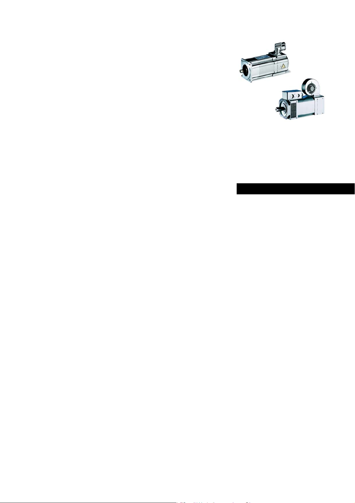
M...
MCA, MCS, MCM, MQA, MDKS
0.5 Nm ... 1100 Nm
Asynchronous servo motors / synchronous servo
motors
Operating Instructions EN
.R./
Ä.R./ä
Page 2

Please read these instructions before you start working!
Follow the enclosed safety instructions.
0Abb.0Tab. 0
Page 3

Contents i
1 About this documentation 5......................................................
1.1 Document history 5.....................................................
1.2 Conventions used 6......................................................
1.3 Terminology used 6.....................................................
1.4 Notes used 7...........................................................
2 Safety instructions 8.............................................................
2.1 General safety instructions for drive components 8...........................
2.2 Application as directed 9................................................
2.3 Foreseeable misuse 9....................................................
2.4 Residual hazards 9......................................................
3 Product description 11.............................................................
3.1 Identification 11.........................................................
3.1.1 Motor code 12...................................................
3.1.2 Nameplate 17...................................................
4 Technical data 19.................................................................
4.1 General data and operating conditions 19..................................
4.1.1 Setting the switching frequency to the rated motor data 20............
5 Mechanical installation 21.........................................................
5.1 Important notes 21.......................................................
5.2 Preparation 21...........................................................
5.3 Assembly of built-on accessories 21.........................................
5.3.1 Installation 22...................................................
5.4 Holding brake (option) 23.................................................
5.4.1 Permanent magnet holding brakes 24..............................
5.4.2 Spring-applied holding brakes 26..................................
6 Electrical installation 28...........................................................
6.1 Important notes 28.......................................................
6.2 EMC-compliant wiring 29..................................................
6.3 Plug connectors 29.......................................................
6.3.1 Power connections / holding brake 30...............................
6.3.2 Fan 30.........................................................
6.3.3 Feedback system 31..............................................
6.4 Terminal box 32.........................................................
6.4.1 Power connections 33............................................
6.4.2 Holding brake DC 205 V - connected via rectifier (optionl) 33...........
6.4.3 Holding brake DC 24 V (optional) 34................................
6.4.4 Fan 34.........................................................
6.4.5 Feedback system 34..............................................
Lenze • BA 33.0006 • 5.1
3
Page 4

Contentsi
7 Safety engineering 36.............................................................
8 Commissioning and operation 37...................................................
8.1 Important notes 37.......................................................
8.2 Before switching on 37...................................................
8.3 Functional test 38........................................................
8.4 During operation 38......................................................
9 Maintenance/repair 39............................................................
9.1 Important notes 39.......................................................
9.2 Maintenance intervals 39..................................................
9.2.1 Motor 39.......................................................
9.2.2 Safety encoder 39...............................................
9.2.3 Holding brake 40................................................
9.3 Maintenance operations 40................................................
9.3.1 Blower 40......................................................
9.3.2 Fan with dust protection filter 41..................................
9.3.3 Motors with bearing relubricating devices 41........................
9.3.4 Motor plug connection assignment 42..............................
9.3.5 Power connection cable connectors 42..............................
9.3.6 Cable connectors 43.............................................
9.4 Repair 44...............................................................
10 Troubleshooting and fault elimination 45............................................
4
Lenze • BA 33.0006 • 5.1
Page 5
About this documentation
1 Aboutthis documentation
Contents
• The present documentation serves to safely work on and with the drives. It
includes safety instructions which must be observed.
• All persons working on and with the drives must have the documentation
available and must observe the information and notes relevant for their work.
• The documentation must always be in a complete and perfectly readable state.
If the information provided in this documentation is not sufficient in your case, please
refer to the controller or gearbox documentation.
Tip!
Information and tools concerning the Lenze products can be found in the
download area at
www.lenze.com
1
Document history
Validity
This documentation applies to servo motors:
Type Name
MCS
MCM
MCA
MQA
MDKS Synchronous servo motors
Synchronous servo motors
Asynchronous servo motors
Target group
This documentation is directed at qualified skilled personnel according to IEC 60364.
Qualifiedskilled personnel arepersonswhohave therequired qualificationstocarry out
all activities involved in installing, mounting, commissioning, and operating the
product.
1.1 Document history
Material number Version Description
13302706 1.0 07/2009 TD09 First edition of the operating instructions,
13340243 2.0 06/2010 TD09 Complete revision
13459473 3.0 01/2014 TD09 Revision of several chapters
--- 4.0 --- TD09 Cancelled
13491314 5.0 04/2015 TD09 Complete revision with supplement of the MCM
.R./ 5.1 07/2015 TD09 Changes of the nameplates MCA, MCM, MCS and
separate from three-phase AC motors
Implementation of new layout
motor
MQA
Lenze • BA 33.0006 • 5.1
5
Page 6
1
About this documentation
Conventions used
1.2 Conventions used
This documentation uses the following conventions to distinguish different types of
information:
Type of information Writing Example/notes
Spelling of numbers
Decimal Normal spelling Example: 1234
Decimal separator Point The decimal point is always used.
Icons
Page reference
Documentation reference
Wildcard
For example: 1234.56
Reference to another page with additional
information
For instance:
Reference to another documentation with
additional information
Example:
Wildcard for options, selection data
16=seepage16
EDKxxx = see EDKxxx documentation
1.3 Terminology used
Term Describes the following
Motor Servo motor in the designs according to motor code, 12 to 16
Inverter Any servo inverter
Drive system Drive systems with servo motors and other Lenze drive components
Any frequency inverter
6
Lenze • BA 33.0006 • 5.1
Page 7
About this documentation
1.4 Notes used
The followingpictographs and signalwords are used in thisdocumentation to indicate
dangers and important information:
Safety instructions
Layout of the safety instructions:
Danger!
(characterises the type and severity of danger)
Note
(describes the danger and gives information about how to prevent
dangerous situations)
Pictograph and signal word Meaning
Danger of personal injury through dangerous electrical
voltage
Danger!
Danger!
Stop!
Reference to an imminent danger that may result in death
or serious personal injury if the corresponding measures are
not taken.
Danger of personal injury through a general source of
danger
Reference to an imminent danger that may result in death
or serious personal injury if the corresponding measures are
not taken.
Danger of property damage
Reference to a possible danger that may result in property
damage if the corresponding measures are not taken.
1
Notes used
Application notes
Pictograph and signal word Meaning
Note!
Tip!
Important note to ensure trouble-free operation
Useful tip for easy handling
Reference to another document
Lenze • BA 33.0006 • 5.1
7
Page 8

2
2 Safetyinstructions
2.1 General safety instructions for drive components
Safety instructions
General safety instructions for drive components
Danger!
Disregarding the following basic safety measures may lead to severe
personal injury and damage to material assets!
Note!
Safety-related parameters of safety encoders used can be obtained from
the SISTEMA database, the Lenze AKB (Application Knowledge Base) or
the data sheet of the encoder manufacturer.
• Transport and storage in a dry, low-vibration environment without aggressive
atmosphere; preferably in the packaging provided by the manufacturer.
– Protect against dust and impacts.
– Observe climatic conditions according to the technical data.
• Use load carrying equipment for transport! 21)
• Lenze drive and automation components ...
... must only be used as intended.
... must never be commissioned despite noticeable damage.
... must never be technically changed.
... must never be commissioned in an incompletely mounted state.
... must never be operated without the required covers.
... may have live, moving or rotary parts during and after operation - corresponding
to their type of protection. Surfaces may be hot.
... must not be operated with large vibrations.
... must not be operated in the frequency range of a plant or the drive system.
• All specifications of the corresponding enclosed documentation must be
observed.
This is vital for safe and trouble-free operation and for achieving the specified
product features.
• Only qualified skilled personnel are permitted to work with or on Lenze drive and
automation components.
According to IEC 60364 or CENELEC HD 384, these are persons ...
... whoare familiarwith theinstallation, assembly, commissioning and operationof
the product,
... possess the appropriate qualifications for their work,
... and are acquainted with and can apply all the accident prevent regulations,
directives and laws applicable at the place of use.
8
Lenze • BA 33.0006 • 5.1
Page 9

Safety instructions
Application as directed
2.2 Application as directed
Low-voltage machines are not household appliances, but are intended as components
that are only applied for re-use for industrial or professional purposes in terms of
IEC/EN 61000-3-2.
They meet the requirements of t he 2014/35/EU Low-Voltage Directive and the
harmonised standards of the IEC/EN 60034 series.
Low-voltage machines with IP23 protection or less are only intended for outdoor use
when applying special protective features.
The integrated brakes must not be used as safety brakes. It cannot be ruled out that
interference factors which cannot be influenced cause a brake torque reduction.
•Drives
– ... must only be operated under the operating conditions and power limits
specified in this documentation.
– ... comply with the protection requirements of the EU Low-Voltage Directive.
2
Any other use shall be deemed inappropriate!
2.3 Foreseeable misuse
• Do not operate the motors
– ... in explosion-protected areas
– ... in aggressive environments (acid, gas, vapour, dust, oil)
– ... in water
– ... in radiation environments
Note!
Increased surface and corrosion protection can be achieved by using
adapted coating systems.
2.4 Residual hazards
Protection of persons
• The motor surfaces can become very hot. Danger of burns when touching!
– Provide protection against accidental contact, if necessary.
• Highfrequency voltages can be capacitively transferred to the motor housing
through the inverter supply.
– Earth motor housing carefully.
• Danger of unintentional starting or electrical shocks
– Connections must only be made when the equipment is deenergised and the
motor is at standstill.
– Installed brakes are no fail-safe brakes.
Lenze • BA 33.0006 • 5.1
9
Page 10

2
Motor protection
• Installed thermal detectors are no full protection for the machine.
Safety instructions
Residual hazards
– If required, limit the maximum current, parameterise the controller such that it
will be switched off after some seconds of operation with I > I
there is the danger of blocking.
, especially if
N
– Installed overload protection does not prevent an overload under any
conditions.
• Installed brakes are no fail-safe brakes.
– The torque may be reduced by disruptive factors that cannot be influenced such
as ingressing oil.
• Fuses are no motor protection.
– Use current-dependent motor protection switches at average operating
frequency.
– Use installed thermal detectors at high operating frequency.
• Too high torques cause a fraction of the motor shaft.
– The maximum torques according to catalogue must not be exceeded.
• Lateral forces from the motor shaft may occur.
– Align shafts of motor and driving machine exactly to each other.
• If deviations from normal operation occur, e.g. increased temperature, noise,
vibration, determine the cause and, if necessary, contact the manufacturer. If in
doubt, switch off the motor.
Fire protection
• Fire hazard
– Prevent contact with flammable substances.
10
Lenze • BA 33.0006 • 5.1
Page 11
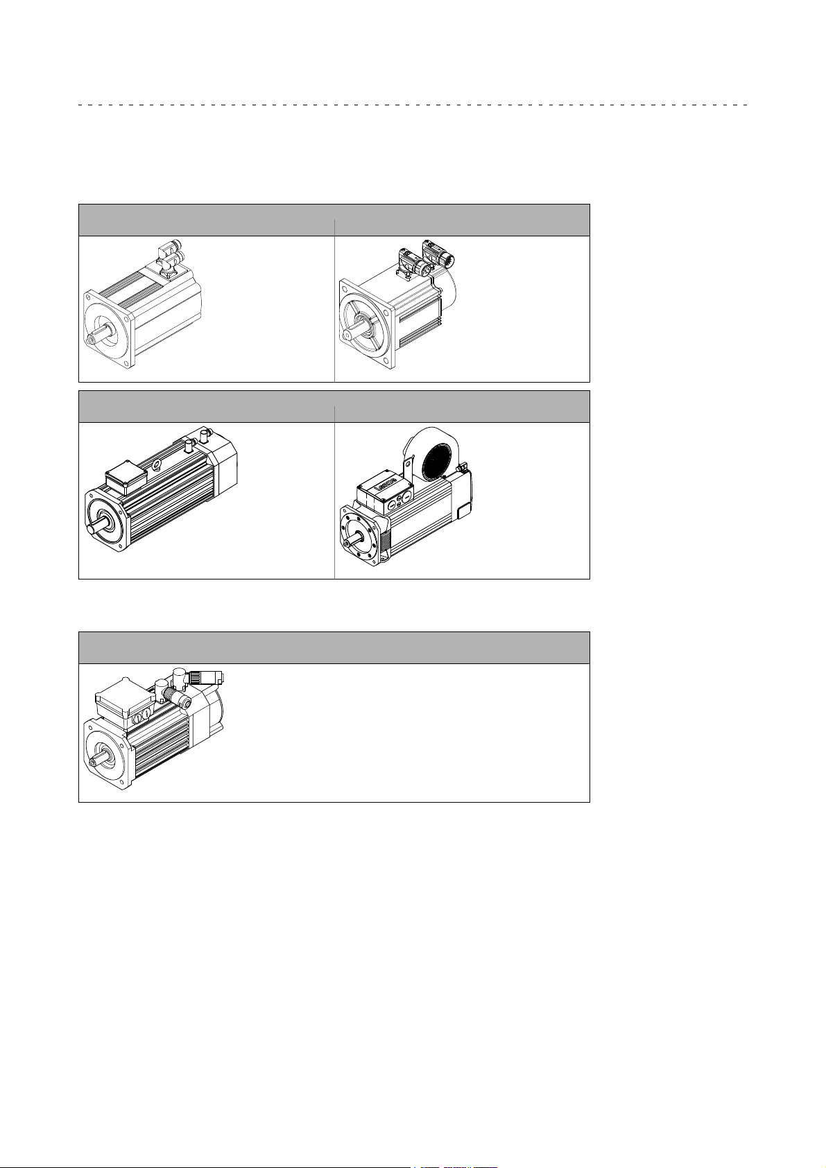
3 Productdescri ption
3.1 Identification
MC, MQA type
Synchronous servo motors
MCS MCM
MT-MCS-001.iso MT-MCM-002.iso
Asynchronous servo motors
MCA MQA
Product description
Identification
3
MD... type
Synchronous servo motors
MDKS
MT-MCA-001.iso MT-MQA-001.iso
MT-MDFKS-001.iso
Lenze • BA 33.0006 • 5.1
11
Page 12
3
Product description
Identification
Motor code
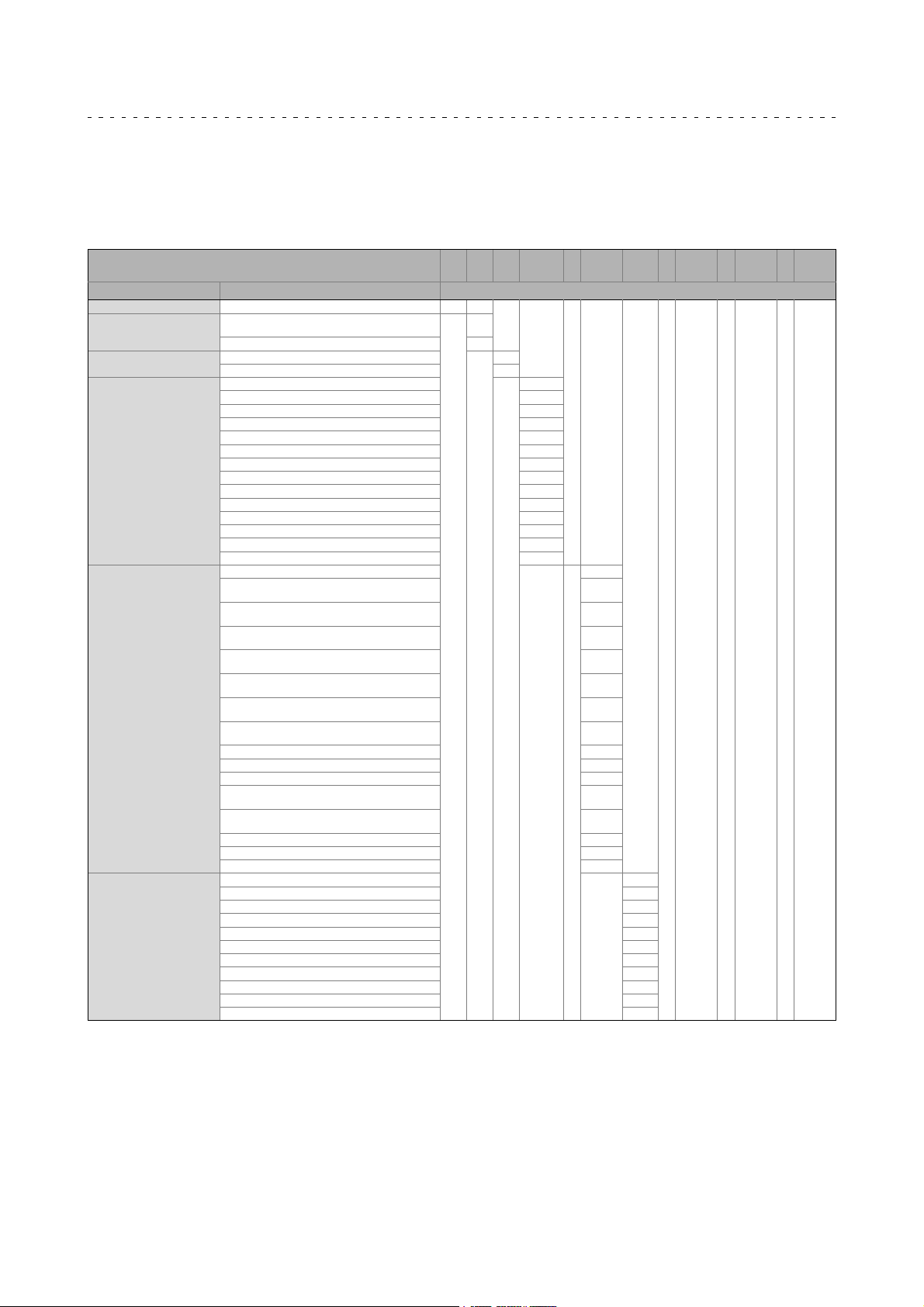
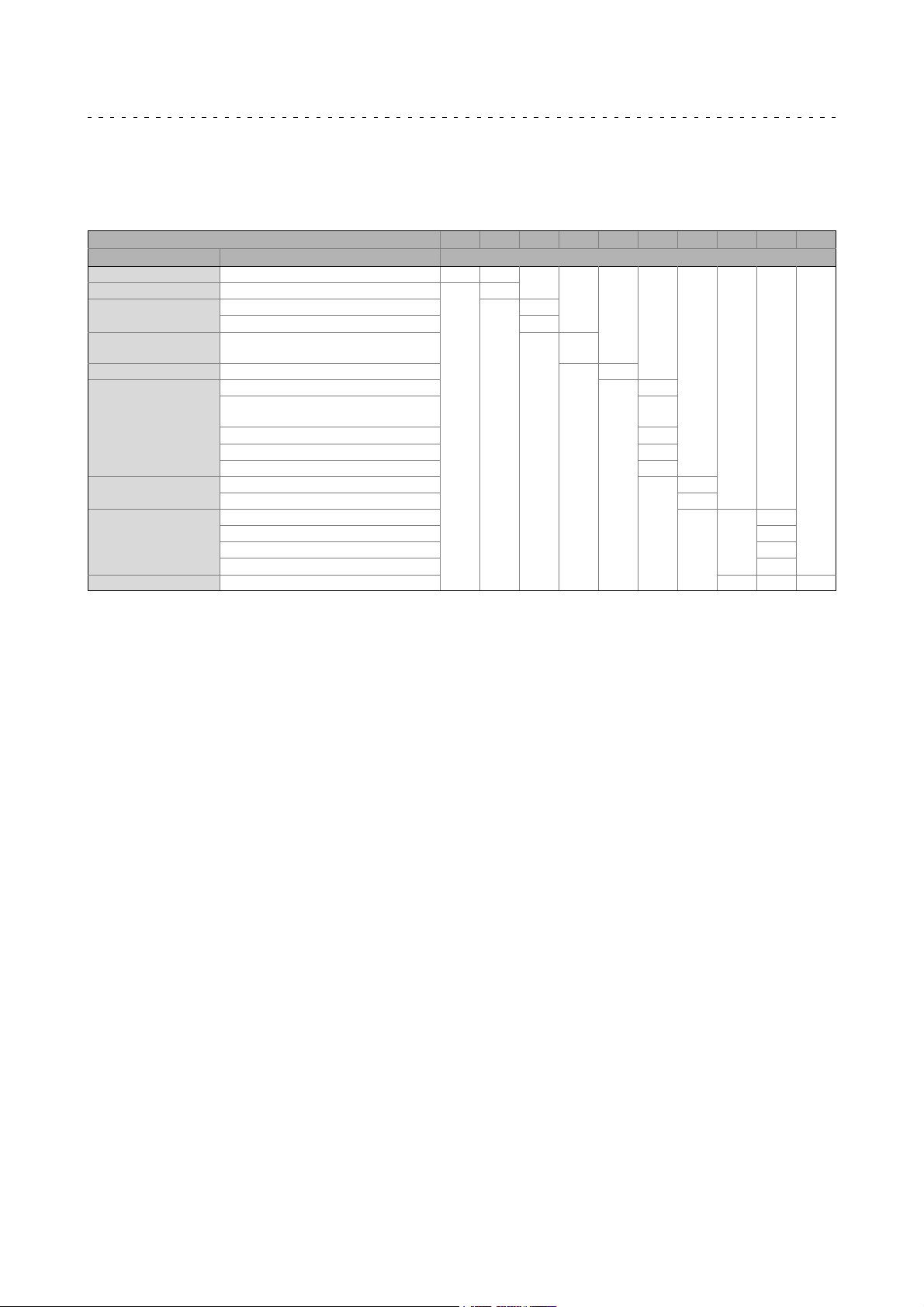
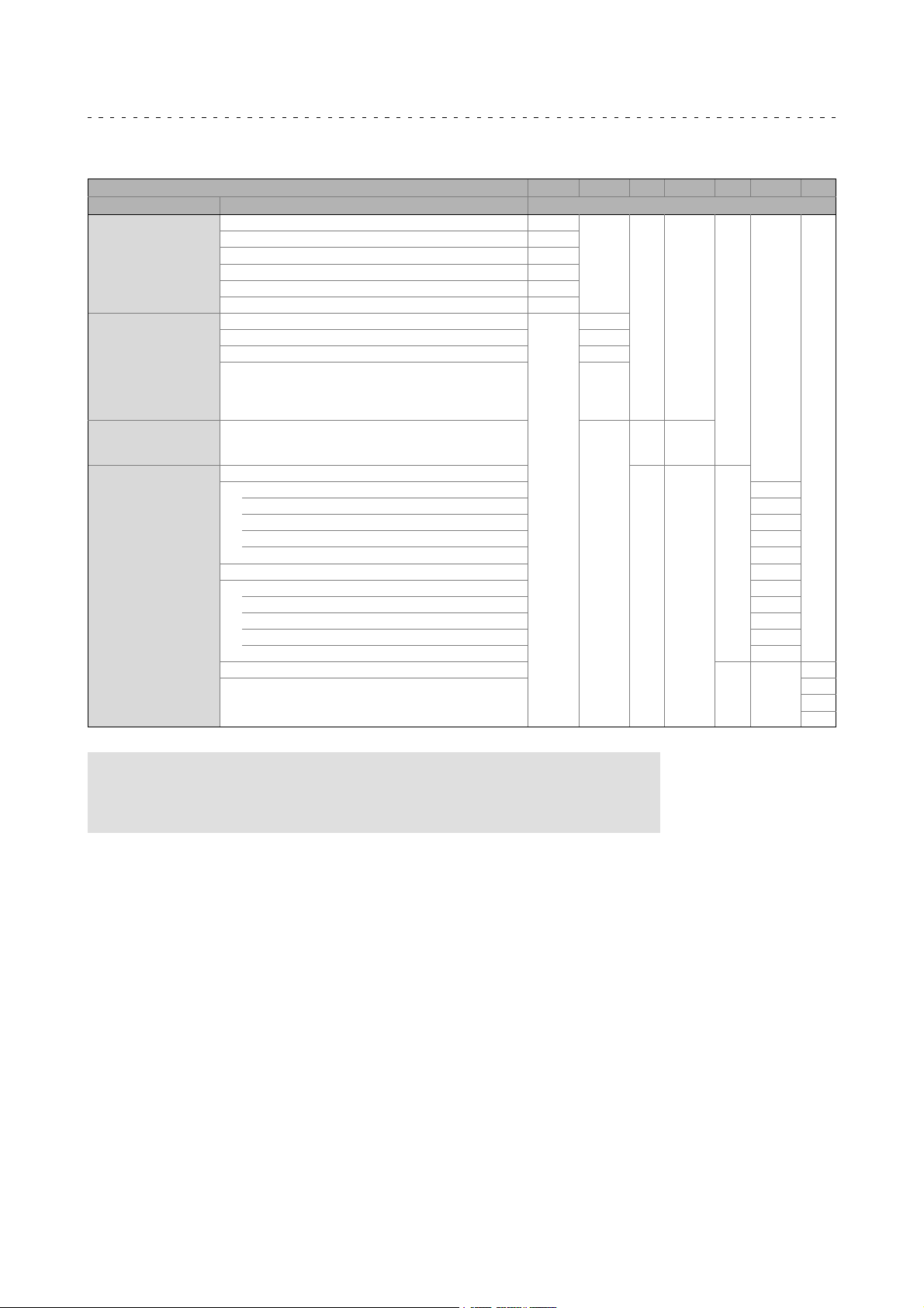
3.1.1 Motor code
MCA; MCS; MQA
servo motors
Example M C A 21X25 - RS0 B0 - A38R - ST5
S00N
Meaning Type Motor code
Product line M
Type
Design
Motor frame size, motor
length, speed
Speed, angle encoder
Brake
Compact servo motors (if required, with axial
ventilation)
Radially ventilated motor Q
Asynchronous A
Synchronous S
Square dimension 62 mm 06
Square dimension 89 mm 09
Square dimension 102 mm 10
Square dimension 116 mm 12
Square dimension 130 mm 13
Square dimension 142 mm 14
Square dimension 165 mm 17
Square dimension 192 mm 19
Square dimension 200 mm 20
Square dimension 214 mm 21
Square dimension 220 mm 22
Square dimension 260 mm 26
Overall length C...X
Speed in 100 rpm XX
Resolver p=1
Multiturn absolute value encoder with sin/cos
signals, Hiperface
Singleturn absolute value encoder with sin/cos
signals, Hiperface
Multiturn absolute value encoder with sin/cos
signals, Hiperface
Singleturn absolute value encoder with sin/cos
signals, EnDat
Multiturn absolute value encoder with sin/cos
signals, EnDat
Multiturn absolute value encoder with sin/cos
signals, EnDat
TTL incremental encoder with commutation signals
UVW (IK4096-5V-T, Renco R35i)
Incremental encoder TTL TXX
Incremental HTL encoder HXX
Resolver p=1 for safety function RV0
Singleturn absolute value encoder with sin/cos
signals, Hiperface for safety function
Multiturn absolute value encoder with sin/cos
signals, Hiperface for safety function
Incremental encoder for safety function S1S
Sin-Cos IG2048-5V-S incremental encoder S20
No encoder NN0
Without brake B0
Spring-applied brake 24V DC F1
Spring-applied brake 24V DC, reinforced F2
Spring-applied brake 205V DC F5
Spring-applied brake 205V DC, reinforced F6
Spring-applied brake 230V AC FG
Spring-applied brake 230V AC, reinforced FH
PM brake 24V DC P1
PM brake 24V DC, reinforced P2
PM brake 205V DC P5
PM brake 205V-DC, reinforced P6
C
RS0
SKM
SRS
SRM
ECN
EQN
EQI
C40
SVS
SVM
- R0SU
12
Lenze • BA 33.0006 • 5.1
Page 13
Product description
Identification
Motor code
3
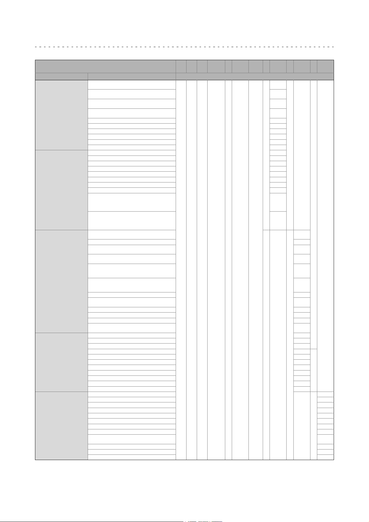
Example M C A 21X25 - RS0 B0 - A38R - ST5
S00N
Meaning Type Motor code
Design
Shaft
Concentricity/vibrational
severity/direct gearbox
attachment
Electrical connection
Enclosure
Cooling
Load flywheel
Motor protection, temperature
protection
Electronic nameplate
Colour/specification
Standard flange formA/FF with throughhole, cyl.
shaft without keyway
Standard flange formA/FF with throughhole, cyl.
shaft with keyway
Standard flange formC/FT with threadedholes, cyl.
shaft without keyway
Standard flange formC/FT with threadedholes, cyl.
shaft with keyway (standard attachment)
Same as version A exceptthat flange is large F
Same as version B exceptthat flange is large G
Same as version C except that flange is large U
Same as version N exceptthat flange is large V
Foot mounting B3 without keyway O
Foot mounting B3 with keyway P
Shaft 11x23 (MCS06) 11
Shaft 14x30 (MCS09; MCA 10) 14
Shaft 19x40 (MCS12; MCA13) 19
Shaft 24x50 (MCS14; MCA14, 17) 24
Shaft 28x60 (MCS19; MCA19) 28
Shaft 38x80 (MA22, 22) 38
Shaft 55x110 (MA26) 55
Concentricity/vibrational severity N, R or V
Direct gearbox attachment: Motor without pinion
for mounting on open gearbox with pinion; flange
for direct gearbox attachment without intermediate
cover, with tapered hollow shaft
Direct gearbox attachment: Motor without pinion
for mounting on open gearbox with pinion; flange
for direct gearbox attachment with intermediate
cover, with tapered hollow shaft
Separate circular connectorsfor power/brake,
encoder/thermal detector, fan
Shared rectangular connector for power, encoder... SQ
Separate terminal boxes for power/brake,
encoder/thermal detector/fan
Separate terminal boxes for power/brake, blower
circular connectors for encoder, thermal detector
Terminal box for power+brake; circular connector
for encoder and thermal detector; circular connector
for blower
Circular connector for power+brake; circular
connector for encoder+thermal detector; terminal
box for fan
IP23 2
IP54 without shaftsealing ring (except for direct
gearbox attachment)
IP65 with shaft sealing ring 6
IP64 (A-flange, without shaft sealing ring) / IP65 A
IP54 with shaft sealing ring (A-end bearing, oil-tight) B
IP54 with shaft sealing ring, double lip (A-end
bearing dust-tight)
Natural ventilation /without fan D
Natural ventilation /without fan S00
Blower 230V; AC; 1N; filter F1F
Blower 400V; AC; 3N; filter F3F
Blower 480V; AC; 3N FWO
Blower 230V; AC; 1N F10
Blower 400V; AC; 3N F30
Blower 115V; AC; 1N F50
Blower 480V; AC; 3N; filter FWF
Without additional load flywheel N
With additional mass inertia J
NC thermal contact
KTY + PTC (MCS09...19) D
KTY sensor; electronic nameplate E
KTY sensor R
KTY - TCO NC contact (standard MQA) T
Standard nameplate 0
Standard nameplate +electronic nameplate 1
Second nameplate supplied loose 2
Second nameplate supplied loose + electronic
nameplate
Colour: black S
Specification - UL design and CSA design, approval U
Specification - UL design, approval R
A
B
C
N
-
Z0X
Y0X
ST
KK
KG
KS
SK
5
C
-
- R0SU
B
-
3
Lenze • BA 33.0006 • 5.1
13
Page 14
3
Product description
Identification
Motor code
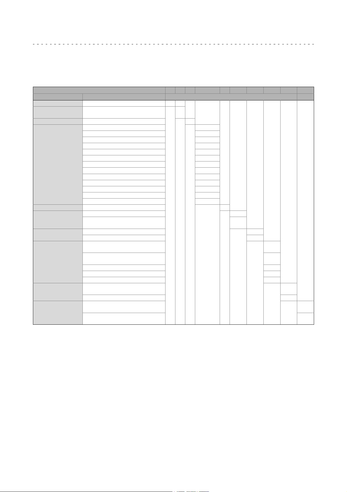
MCM
servo motors
Example M C M 06 B 30 - RS0 B0 A11 ST S00 RU
Meaning Type Motor code
Product line M
Type Compact servo motors (if required,
Design Synchronous M
Motor frame size
Motor length
Speed 100 rpm 3000 30
Mains voltage 400 V Speed sensor, angle
sensor
Brake
Design
Shaft
Electrical connection Separate circular connectors for
Cooling Natural ventilation / without fan S00
Motor protection,
temperature
Specification Specification - UL design and CSA
with axial ventilation)
Square dimension 62 mm 06
Square dimension 89 mm 09
Square dimension 116 mm 12
20 B
30 C
40 D
50 E
60 F
70 G
80 H
90 I
100 J
Resolver p=2 RS0
Multiturn absolute value encoder with
sin/cos signals, Hiperface
Without brake B0
Spring-applied brake 24V DC F1
Standard flange form A/FF with
through hole, cyl. shaft without keyway
Standard flange form A/FF with
through hole, cyl. shaft with keyway
Shaft 11x23 (MCM06) 11
Shaft 14x30 (MCM09) 14
Shaft 19x40 (MCM12) 19
power/brake, encoder/KTY
KTY sensor R
design, approval
C
SKM
A
B
ST
U
14
Lenze • BA 33.0006 • 5.1
Page 15
Product description
Identification
Motor code
MDKS
servo motors
Example M D S K S AG 056 - 1 3
Meaning Type Motor code
Product line M
Type Three-phase AC current D
Cooling
Design, housing Compact servo motor with square
Machine type Synchronous machine S
Built-on accessories
Size
Overall length
Number of pole pairs 3
Forced ventilated F
Natural ventilation S
housing and cooling ribs
Absolute value encoder AG
Brake and sin-cos absolute value
encoder or SSI absolute value encoder
Brake and resolver BS
Resolver RS
Resolver for safety function RV
K
BA
056
071
0
1
2
3
3
Lenze • BA 33.0006 • 5.1
15
Page 16
3
Product description
Identification
Motor code
Encoder code
Example SFC 1024 - 8V - K 2
Meaning Type Encoder code
Product line
Number
Voltage Medium supply voltage
Interface or
signal level
Resolver RS
Resolver for safety function RV
Incremental encoder IG
Incremental encoder with commutation signal IK
Singleturn absolute value encoder SFC
Multitum absolute value encoder AM
2-pole resolver for servo motors 0
2-pole resolver for three-phase AC motors 1
Number of pole pairs for resolvers 2, 3, 4,...
Number of steps / increments per revolution 32, 128,
Standard
TTL T
HTL (for incremental encoders) H
Hiperface (for absolute value encoders) H
EnDat E
sin/cos 1 V
For safety function
TTL U
HTL (for incremental encoders) K
Hiperface (for absolute value encoders) K
EnDat F
sin/cos 1 V
Safety integration level (SIL) 1
ss
ss
512,
1024,
2048, ...
5V, 8V,
15V,
24V, ...
S
-
V
2
3
4
Note!
If feedback systems for safety functions are used, the manufacturer’s
documentation must be observed!
16
Lenze • BA 33.0006 • 5.1
Page 17
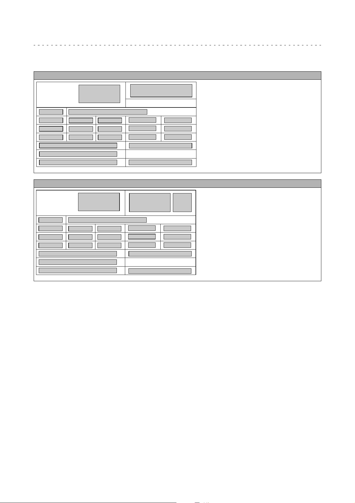
3.1.2 Nameplate
Asynchronous and synchronous servo motors
Product description
Nameplate
3
L
2
5.5
5.6
5.7
1
4
5.8
5.9
14.2
9
8
10.2/10.3
MCM synchronous servo motors
L
2
5.5
5.6
5.7
1
4
5.8
5.9
14.2
9
8
10.2/10.3
9
5.2
5.10
14.1
9
5.2
5.10
14.1
18
18
15
5.4
16.6
27
12
11
15
5.4
16.6
27
12
11
5.3
22
14.3
MT-SYN-001.des
43
5.3
22
14.3
MT-MCM-00X.des
Lenze • BA 33.0006 • 5.1
17
Page 18

3
Product description
Nameplate
Pos. Contents
1 Manufacturer / production location
2 Type of motor / standard
3 Gearbox type
4 Motor type
5
6 Mounting position / position of the system blocks
7
8
9 For feedback / pulse encoder or resolver data see encoder code 16
10
11 Bar code
12 Motor number
13 Information with regard to the operating mode
14
15 Applicable conformities, approvals and certificates
16
17 Application factor (specified if <1.0) / load capacity
18 Year of manufacture / week of manufacture
19 UL file number
20 Additional customer data
21 UL category (e.g. inverter duty motor)
22 C86 = motor code for controller parameterisation (code 0086)
23 Efficiency class
24 Partial load efficiencies for 50Hz operation at a rated power of 50% and 75%
25 Range A Voltage tolerance range according to range A as specified by IEC/EN 60034-1
27 Permissible ambient temperature (e.g. Ta 40°C)
29 Standstill current (ampere locked rotor ALR)
30 Weight
31 Plug design (number of poles)
43 Internal key: QR code
Technical data
5.1 Ratio
5.2 Rated torque
5.3 Rated speed
5.4 Rated frequency
5.5 Rated voltage
5.6 Rated current
5.7 Maximum current
5.8 Rated power [kW]
5.9 Rated power [HP]
5.10 Continuous standstill torque
Lubricant details
7.1 Lubricant amount
7.2 Lubricant type
Brake data
8.1 Type
8.2 AC/DC brake voltage
8.3 Braking torque, electrical power input
Production data
10.1 Order number
10.2 Material number
10.3 Serial number
Additional motor specifications
14.1 Temperature class
14.2 Enclosure
14.3 Motor protection
Rated data for various frequencies
16.1 Hz = frequency
16.2 kW = motor power
16.3 rpm = motor speed
16.4 V = motor voltage
16.5 A = motor current
16.6
16.7 = motor efficiency: at a rated power of 100%
cos = motor power factor for MA
Uin[V] = induced voltage for MC
18
Lenze • BA 33.0006 • 5.1
Page 19
Technical data
General data and operating conditions
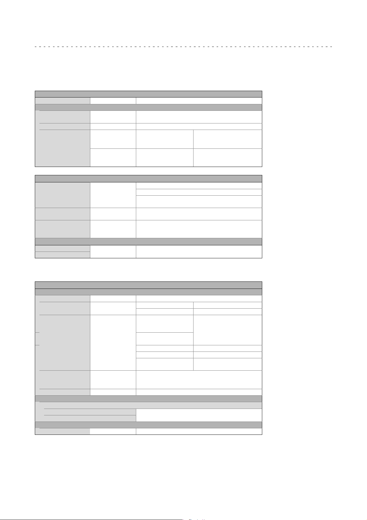
4 Technicaldata
4.1 General data and operating conditions
General data
Conformity
CE 2006/95/EC Low-Voltage Directive
Approvals
UL ANSI/UL 1004-1
CSA CSA-C22.2 No. 100 Motors and Generators
EAC
Protection of persons and devices
Enclosure IEC/EN 60034-5
Temperature class F (155 °C)
Permissible voltage As specified by limiting curve A of the pulse voltage from
EMC
Noise emission
Noise immunity
ANSI/UL 1004-6
(TR CU 020/2011)
(TR CU 004/2011)
IEC/EN 60034-1
IEC/EN 61800-3 Depending on the controller, see documentation for the
Rotating Electrical Machines
Servo and Stepper Motors
Electromagnetic
compatibility of technical
means
On safety of low voltage
equipment
See nameplate
Degrees of protection only apply to horizontal installation
All unused connectors must be closed with protection
covers or blanking plugs.
Exceedance of the temperature limit weakens or destroys
the insulation
IEC / TS 60034-25:2007 (corresponds to IVIC
C/B/B@500V)
controller.
Eurasian Conformity
TR CU: Technical Regulation of
Customs Union
Eurasian Conformity
TR CU: Technical Regulation of
Customs Union
4
Operating conditions
Ambient conditions
Climatic
Transport IEC/EN 60721-3-2 2K3 (-20 °C ... +70 °C)
Storage IEC/EN 60721-3-1
Operation IEC/EN 60721-3-3
Site altitude < 1000 m amsl - without power reduction
Humidity Relative humidity 85 %, without condensation
Electrical
The motor connection type depends on the controller
Length of the motor cable
Length of cable for speed feedback
Mechanical
IEC/EN60721-3-3 3M6
1K3 (-20 °C ... +60 °C) < 3 months
1K3 (-20 °C ... +40 °C) > 3 months
3K3 (-20 °C ... +40 °C) MC
A, MCS,
MDKS
3K3 (-15 °C ... +40 °C) MC
M, MQA
3K3 (-10 °C ... +40 °C) With brake
3K3 (-15 °C ... +40 °C) With blower
> +40 °C With power reduction, see
> 1000 m amsl < 4000m amsl with power reduction, see
catalogue
See inverter instructions
Without brake
catalogue
Lenze • BA 33.0006 • 5.1
19
Page 20

4
Technical data
General data and operating conditions
Setting the switching frequency to the rated motor data
4.1.1 Setting the switching frequency to the rated motor data
The rated data are valid for operation on an inverter with a switching frequency of at
least 8 kHz. If operated at a switching frequency of f
=4 kHz, the following
ch
consequences must be observed.
Motor type Consequences
MQA 20, 22, 26
MCA 20, 22, 26
MCM, MCS
MCA 10, 13, 14, 17, 19, 21
MDKS
At fch= 4 kHz, the motor continuously reaches only approx. 95 % of
its rated torque.
Increased noise emission
All published rated data remain valid if fch=4kHz.
20
Lenze • BA 33.0006 • 5.1
Page 21

Mechanical installation
5 Mechanicalinstallation
5.1 Important notes
Danger!
Some of the motors mounted to the gearboxes are equipped with
transport aids. They are only intended for the mounting/dismounting of
the motor to the gearbox and must not be used for the entire geared
motor!
• Only move the drive with means of transport or hoists that have sufficient
load-bearing capacity.
• Ensure safe fixing.
• Avoid shocks!
5.2 Preparation
5
Important notes
Remove thecorrosion protection fromthe shaft ends and flanges.If necessary, remove
dirt using standard cleaning solvents.
Stop!
Bearings or seals must not come into contact with the solvent - material
damages.
After a long storage period (> 1 year) you have to check whether moisture has
entered the motor. For this purpose, measure the insulation resistance (measuring
voltage 500 V
5.3 Assembly of built-on accessories
Follow these instructions carefully. Please note that the warranty and product liability
will become void in the event of impermissible alterations or modifications to the
motors.
• Mount the transmission elements:
– Shocks and impacts must be avoided! They could destroy the motor.
– For mounting always use the centre bore in the motor shaft as specified by DIN
332-DR-M...
– Tolerances of the shaft ends:
50 mm: ISO k6, > 50 mm: ISO m6.
). In case of values 1kper volt of rated voltage, dry the winding.
DC
• Only use an extractor for the disassembly.
• When using belts for torque/power transmission:
– Tension the belts in a controlled manner.
– Provide protection against accidental contact! During operation, surface
temperatures of up to 140°C are possible.
Lenze • BA 33.0006 • 5.1
21
Page 22

5
5.3.1 Installation
Important notes
• The mounting surface must be dimensioned for the design, weight and torque of
• The foot and flange faces must rest flat on the mounting surface.
Mechanical installation
Assembly of built-on accessories
Installation
the motor.
– Incorrect motor alignment reduces the service life of the roller bearings and
transmission elements.
Impacts on shafts can cause bearing damage.
• Do not exceed the permissible range of ambient operating temperature ( 19).
• Fasten the motor securely.
• Ensure that the ventilation is not impeded. The exhaust air, also the exhaust air of
other machines next to the drive system, must not be taken in immediately.
• During operation, surfaces are hot, up to 140 °C! Ensure that guard preventing
accidental contact is in place!
Note!
From the air inlet to other component parts, a minimum distance of 10%
of the outer diameter of the fan cover must be complied with!
Ensure an even surface, solid foot or flange mounting and exact alignment if a direct
clutch is connected. Avoid resonances with the rotational frequency and double
mains frequency which may be caused during assembly. With an additional support
on the N-end side in the case of flange-mounted motors (in particular for MQA and
great MCA), vibrations that may occur can be reduced. Bracing of the motor by the
additional support must be reliably avoided.
Only mount or remove transmission elements using appropriate means. In order to
facilitate handling, heat them beforehand. Cover belt pulleys and clutches witha touch
guard.
Stop!
Ensure a correct belt tension!
The machines are halfkey balanced. The clutch must be halfkey balanced, too. The
visible jutting out part of the key must be removed.
Designs with shaft end at the bottom must be protected with a cover at the N-end,
preventing the ingress of foreign particles into the fan.
22
Lenze • BA 33.0006 • 5.1
Page 23
Mechanical installation
Holding brake (option)
5.4 Holding brake (option)
Important notes
As an option, the motors can be fitted with a brake. The installation of brakes (in or on
the motor) increases the length of the motor.
Note!
The brakes used are not fail-safe because interference factors which
cannot be influenced (e.g. oil ingress) may lead to a reduction in torque.
The brakes are used as holding brakes and serve to hold the axes at standstill or in the
deenergised state.
Emergency stops at higher speeds are possible but high switching energy increases
wear on the friction surfaces and the hub, 26).
The spring-applied brakes work on the basis of the closed-circuit principle, i.e. the brake
is closed in the deenergised state. The brakes for DC supply can be fed with a
bridge-rectified DC voltage (bridge rectifier) or with a smoothed DC voltage. The
permissible voltage tolerance is ±10 %.
5
Installation
If longmotor supply cables are used,pay attention to the ohmic voltage drop alongthe
cable and compensate for it with a higher voltage at the input end of the cable.
The following applies to Lenze system cables:
U*= UB+
0.08 Ω
m
⋅ L ⋅ I
U* [V] Resulting supply voltage
B
UB[V] Rated voltage of the brake
l[m] Cable length
IB[A] Rated current of the brake
Stop!
If no suitable voltage (incorrect value, incorrect polarity) is applied to the
brake, the brake will be applied and can be overheated and destroyed by
the motor continuing to rotate.
The shortest operating times of the brakes are achieved by DC switching of thevoltage
and an external suppressor circuit (varistor or spark suppressor). Without suppressor
circuit, the operating times may increase. A varistor/spark suppressor limits the
breakingvoltage peaks.Itmust beensured thatthe power limitofthe s uppressor circuit
is not exceeded. This limitdepends onthe brakecurrent, brakevoltage, disengagement
time and the switching operations per time unit.
Furthermore the suppressor circuit is necessary for interference suppression and for
increasing the servicelife of therelay contacts(external, not integratedinto the motor).
Please refer to the catalogue for servo motors for detailed information
about holding brakes.
Note!
The brake cannot be readjusted. When the wear limit is reached, the
brake has to be replaced.
Lenze • BA 33.0006 • 5.1
23
Page 24
5
5.4.1 Permanent magnet holding brakes
These brakesare used as holding brakesand serve to hold theaxes without backlashat
standstill or in the deenergised state.
Mechanical installation
Holding brake (option)
Permanent magnet holding brakes
Stop!
• Inherent to the design, the rated torque for permanent magnet
holding brakes is solely classified as holding torque at standstill. When
braking from full motor speed,
e.g. in the case of emergency stops, the braking torque is substantially
reduced.
• This holding brake is only designed for a limited number of emergency
stops. Utilisation as a working brake, e.g. to decelerate a load, is not
permissible.
When activating the brake, it must be ensured that thebrake is released or engaged at
zero speed to avoid unnecessary and rapid wear of the brake.
When used solely as holding brakes, the brakes are virtually wear free on their
friction surfaces. If the max. permissible switching energy per emergency stop (see
catalogue) is not exceeded, at least 2000 emergency stop functions from a speed of
3000 rpm are possible.
W = ½ ⋅ J
The holding torques specified in the catalogue only apply when the motor is at
standstill. In the case of a slipping brake, the dynamic braking torque always applies
which depends on the speed.
tot
⋅ ω
2
J
[kgm2] Total moment of inertia
tot
[1/s] Angular velocity =2n/60, n= speed [rpm]
W[J] Energy
Note!
The permanent magnet holding brakes are maintenance-free and cannot
be adjusted. In the event of wear, e.g. by emergency stops, the brakes
must be replaced.
These brakes work on the basis of the closed-circuit principle, i.e. the brake is closed in
the deenergised state.
Brakes with a rated voltage of DC 24 V are designed for smoothed DC voltages with a
ripple of<1 %. It must be ensuredthat the connector on themotor side issupplied with
theminimum voltageof DC24 V-10 %. Ifnecessary, thevoltage drop inthecable should
also be considered. If the maximum voltage DC 24 V + 5 % is exceeded, the brake can
close again. Supplying the brake with bridge-rectified DC voltage (bridge rectifier
without additional smoothing) or a DC voltage with a ripple of >1 % can lead to a
malfunctioning of the brake or an increase in the engagement and disengagement
times.
Brakes with a rated voltageof DC205 V aredesigned forbridge-rectified DC voltage, i.e.
for supply via a bridge rectifier from the 230 V mains (half-wave rectifiers are not
permissible). Supplying the brake with smoothed DC voltage can lead to
malfunctioning or an increase in the engagement and disengagement times. With
regardto the minimumandmaximum voltages, thesame conditionsapplyasfor brakes
with 24 V, i.e. the permissible voltage tolerance is 205 V DC +5 %, -10 %.
24
Lenze • BA 33.0006 • 5.1
Page 25
Mechanical installation
Holding brake (option)
Permanent magnet holding brakes
Wear of permanent magnet brakes
If applied asdirected (application as holding brakes), the permanent magnet brakes of
the servo motors are wear free and intended forlong operating times. The wear on the
friction lining is due to e.g. emergency stops.
The table below describes the different reasons for wear and their impact on the
components of the permanent magnet brakes.
Component Effects Influencing factors Cause
Friction lining /
friction surface at
thearmatureplate
and external pole
Springs Fatigue failure of the
Permanent magnet Useless brake Temperature, overvoltage Excessive overvoltages /
Wear on the friction lining Applied friction energy
springs
Number of switching
operations of the brake
Braking during operation
(impermissible, holding
brakes!)
Emergency stops
Overlapping wear when
the drive starts and stops
Active braking by the drive
motor with the help of the
brake (quick stop)
Axial duty cycle of the
springs
temperatures
5
Stop!
In case of wear above the maximum air gap ( brake operating
instructions), application of the brake cannot be ensured. In this case, no
braking process is carried out.
Lenze • BA 33.0006 • 5.1
25
Page 26
5
Mechanical installation
Holding brake (option)
Spring-applied holding brakes
5.4.2 Spring-applied holding brakes
These brakesare used as holding brakesand serve to hold theaxes without backlashat
standstill or in the deenergised state.
For permissible operating speeds and characteristics, please see the motor catalogue
applicable in each case. Emergency stops at higher speeds are possible, but high
switching energy increases wear on the friction surfaces and the hub.
Stop!
The friction surfaces must always be free from oil and grease because
even small amounts of grease or oil will considerably reduce the braking
torque.
The formula below provides a simplified way to calculate friction energy per switching
cycle which must not exceed the limit value for emergency stops that depends on the
operating frequency (motor catalogue; Lenze drive solutions: formulas,
dimensioning, and tables).
Q[J] Friction energy
J
[kgm2] Total mass inertia (motor + load)
tot
L
[1/s] Angular velocity =2n/60, n= speed [rpm]
MK[Nm] Characteristic torque
ML[Nm] Load torque
Q = ½ ⋅ J
⋅ Δω2⋅
tot
M
K
MK− M
Depending on the operating conditions and possible heat dissipation, surface
temperatures can be up to 130 °C.
More detailed information on the used brakes is provided in the
corresponding catalogues.
Wear on spring-applied brakes
Spring-applied brakesare wear-resistant and designed forlong maintenanceintervals,
23).
However,the friction lining,theteeth betweenthe brakerotorand thehub,and also the
braking mechanism are naturally subject to function-related wear which depends on
the application case (seetable). Inorder toensure safeand problem-freeoperation, the
brake must therefore be checked and maintained regularly and, if necessary, replaced
(see brake maintenance and inspection).
The following table describes the different causes of wear and their effect on the
components of the spring-applied brake. In order to calculate the useful lifeof therotor
and brake and determine the maintenance intervals to be prescribed, the relevant
influencing factors must be quantified. The most important factors are the applied
friction energy, the starting speed of braking and the switching frequency. If several of
the indicated causes of wear on the friction lining occur in an application, their effects
are to be added together.
26
Lenze • BA 33.0006 • 5.1
Page 27

Mechanical installation
Component Effect Influencing factors Cause
Friction lining Wear on the friction lining Applied friction energy
Number of start-stop
cycles
Armature plate and
flange
Teeth of the brake
rotor
Armature plate
bracket
Springs Fatigue failure of the
Running-in of armature
plate and flange
Teeth wear (primarily at
the rotor end)
Armature plate, cap screws
and bolts are deflected
springs
Applied friction energy Friction between the brake
Number of start-stop
cycles,
Level of the braking
torque,
Dynamics of the
application,
Speed fins in operation
Number of start-stop
cycles,
Level of braking torque
Number of switching
operations of the brake
Braking during operation
(impermissible, holding
brakes!)
Emergency stops
Overlapping wear when
the drive starts and stops
Active braking by the drive
motor with the help of the
brake (quick stop)
Starting wear if motor is
mounted in a position
with the shaft vertical,
even if the brake is open
lining and the armature
plateorflangee.g.during
emergency braking or
service brake operation
Relative movement and
impacts between brake
rotor and brake hub
Load changes and impacts
due to reversal error
during interaction
between armature plate,
cap screws and guide bolts
Axial load cycle and
shearing stress on the
springs due to radial
reversing error of the
armature plate
5
Holding brake (option)
Spring-applied holding brakes
Lenze • BA 33.0006 • 5.1
27
Page 28

6
6 Electricalinstallation
6.1 Important notes
Electrical installation
Important notes
Danger!
Hazardous voltage on the power connections even when disconnected
from mains: residual voltage >60 V!
Before working on the power connections, always disconnect the drive
component from the mains and wait until the motor is at standstill.
Verify safe isolation from supply!
Stop!
Electrical connections must be carried out in accordance with the
national and regional regulations!
Observe tolerances according to IEC/EN 60034-1:
– Voltage±5%
– Frequency ±2 %
– Wave form, symmetry (increases heating and affects electromagnetic
compatibility)
Observe noteson wiring,information onthe nameplate, and the connection scheme in
the terminal box.
• The connection must ensure a continuous and safe electrical supply, i.e.
– no loose wire ends,
– use assigned cable end fittings,
– ensure good electrical conductivity of the contact (remove residual lacquer) if an
(additional) PE connection on the motor housing is used),
– establish a safe PE conductor connection,
– tighten the plugin connector to the limit stop.
– After the connection is completed, make sure that all connections on the
terminal board are firmly tightened.
• The smallest air gaps between uncoated, live parts and against earth must not fall
below the following values.
Minimum requirements for basic
insulation according to IEC/EN
60664-1 (CE)
3.87 mm
• The terminal box has to be free of foreign bodies, dirt, and humidity.
• All unused cable entries and the box itself must be sealed against dust and water.
Higher requirements for UL
design
6.4 mm < 178 mm
9.5 mm > 178 mm
Motor diameter
28
Lenze • BA 33.0006 • 5.1
Page 29
Electrical installation
EMC-compliant wiring
6.2 EMC-compliant wiring
The EMC-compliant wiring of the motors is described in detail in the Operating
Instructions for the Lenze controllers.
• Use of metal EMC cable glands with shield connection.
• Connect the shielding to the motor and to the device.
6.3 Plug connectors
The connectors comply with vibration and shock class 3M6 as specified in
IEC/EN60721-3-3. This applies to all power, encoder and fan connector boxes.
Stop!
• Cable connectors with screwed connection:
– Always use with the O-rings supplied.
• Cable connectors with a SpeedTec bayonet lock:
– Remove O-ring and dispose of it.
6
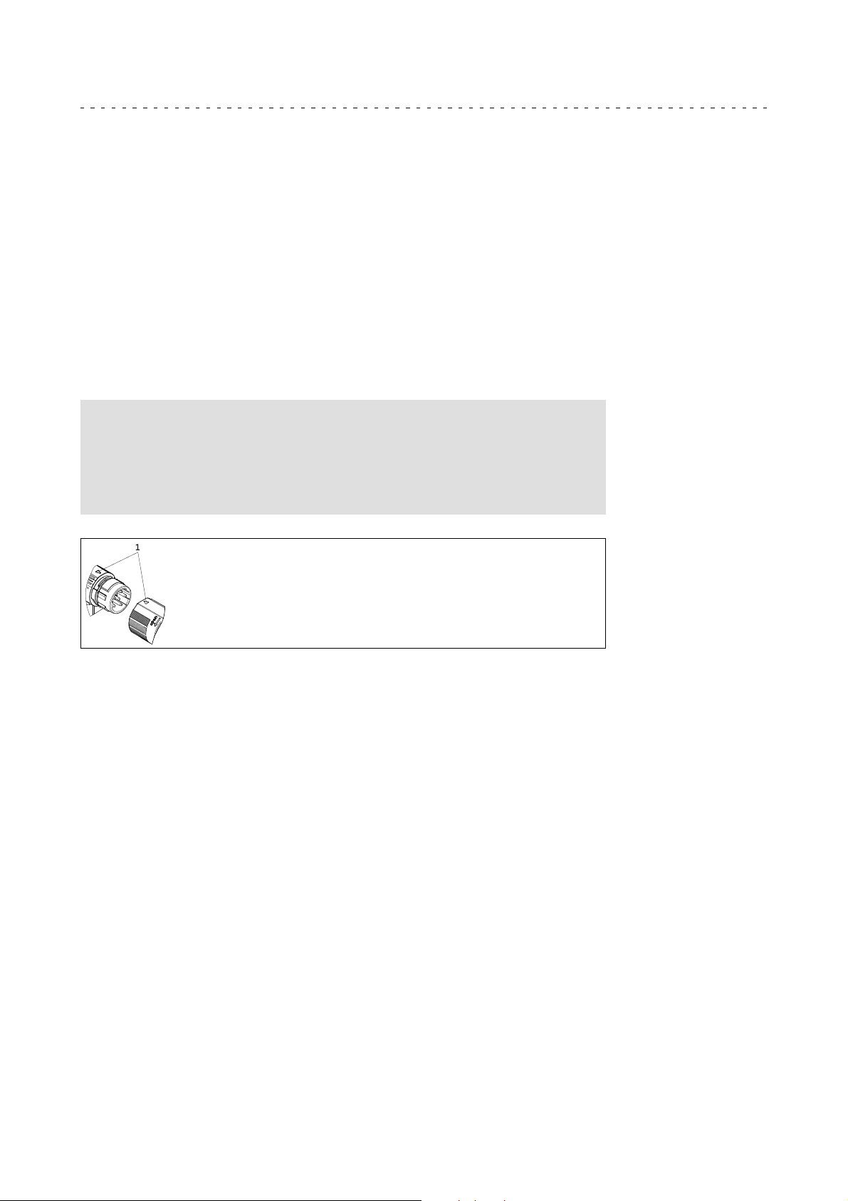
When connecting the cable connector tothe motor connector, make sure that theaids
toorientation (pos. 1)arefacingeach other. Onlythentrouble-free operation isensured.
• Tighten the box nut of the cable connectors!
• Never disconnect cable connectors whilst voltage is being applied! Otherwise the
connector may be destroyed! Inhibit the inverter before disconnecting the plugs!
Lenze • BA 33.0006 • 5.1
29
Page 30
6
Electrical installation
Plug connectors
Power connections / holding brake
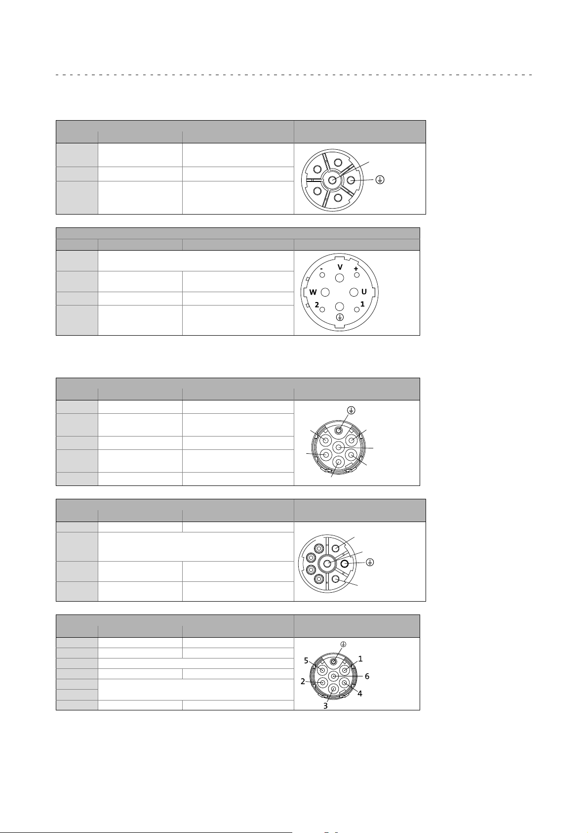
6.3.1 Power connections / holding brake
6-pole (external view of poles)
Contact Name Meaning M23
1
2
PE PE conductor
4
5
6
MCA 19...21, MCS 14...19, MQA 20 (external view of poles)
Contact Name Meaning M40
1
2
+
-
U
V
W
BD1
BD2
U
V
W
Not assigned
BD1
BD2
PE PE conductor
U
V
W
Holding brake +
Holding brake -
Power phase U
Power phase V
Power phase W
Holding brake +
Holding brake -
Power phase U
Power phase V
Power phase W
2
1
6
5
4
6.3.2 Fan
Single-phase (external view of poles)
Contact Name Meaning M17
PE PE conductor
1
2
3 Not assigned
4
5
6 Not assigned
8-pole (external view of poles)
Contact Name Meaning M23
PE PE conductor
1
2
3
A
B
C
D
Three-phase (external view of poles)
Contact Name Meaning M17
PE PE conductor
1 U Fan
2 Not assigned
3 V Fan
4
5
6 W Fan
U1
U2
U+
U-
Not assigned
U1
U2
U+
U-
Not assigned
AC fan
DC fan
AC fan
DC fan
5
2
3
D
C
B
A
1
6
4
3
2
1
30
Lenze • BA 33.0006 • 5.1
Page 31
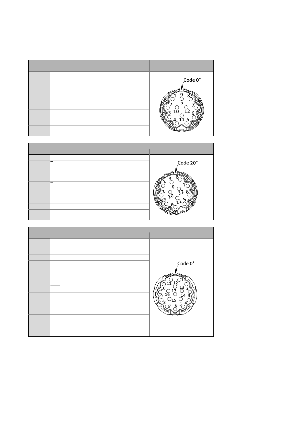
6.3.3 Feedback system
Resolver (external view of poles)
Contact Name Meaning M23
1
2
3 +VCC ENP Supply: electronic nameplate
4
5
6
7
8
9
10 Shield Encoder housing shield
11
12
Incremental encoder / sin/cos absolute value encoder Hiperface (external view of poles)
Contact Name Meaning M23
1 B Track B / + SIN
2
3
4
5
6
7
8 Not assigned
9 B TrackBinverse/-SIN
10 Shield Encoder housing shield
11
12
+Ref
-Ref
+COS
-COS
+SIN
-SIN
Not assigned
+KTY
-KTY
A
A
+U
B
GND
Z
Z
+KTY
-KTY
Transformer windings
(reference windings)
1)
Stator windings cosine
Stator windings
Sine
Thermal detector KTY
TrackAinverse/ -COS
Track A / + COS
Supply +
Mass
Zero track inverse / - RS485
Zero track / + RS485
Thermal detector KTY
Electrical installation
Plug connectors
Feedback system
6
Sin/cos absolute value encoder with EnDat interface ( external view of poles)
Contact Name Meaning M23
1 UPsensor Supply UPsensor
2
3
4 0 V sensor 0 V sensor supply
5
6
7 +U
8
9
10 GND Mass
11 Shield Encoder housing shield
12
13
14 Data Data EnDat interface
15
16
17 Data Data inverse EnDat interface
Not assigned
+KTY
-KTY
B
Cycle
Cycle
B
B
A
A
1) Only for versions with electronic nameplate ENP.
Thermal detector KTY
Supply + / +VCC ENP
Clock pulse EnDat interface
Clock pulse inverse EnDat
interface
Track B
Track B inverse
Track A
Track A inverse
1)
Lenze • BA 33.0006 • 5.1
31
Page 32
6
Electrical installation
Terminal box
Feedback system
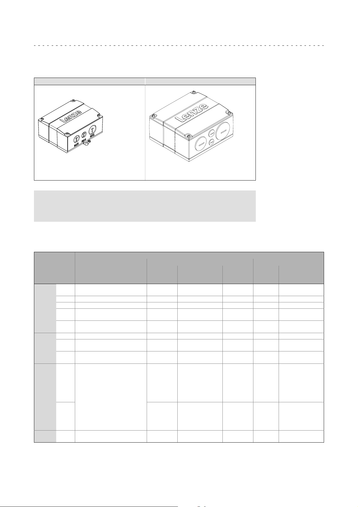
6.4 Terminal box
Terminal box with knock out Terminal box with screwed connections
MT-terminal box-001.iso MT-terminal-box-002.iso
The openings in the terminal box are cast closed
and can be opened by the customer as required.
Note!
Open the holes on the underside of the knock out terminal box when the
cover is closed.
Cable glands and terminal studs for the power terminal box
Motor type /
motor size
MCA
MQA
MCS
MDKS 056,
Tab. 1 Cable glands and connecting terminals
10, 13,
14, 17
19, 21 1xM32x1.5+1xM25x1.5 0.2 ... 10 10 ... 11
20 2xM20+2xM25+2x M32 2.5 ... 16 18 ... 20
22
26
20 2xM20+2xM25+2x M32 2.5 ... 16 18 ... 20
22
26
09, 12,
14D,
14H,
14L15,
14P14,
19F15,
19J15
14L32,
14P32,
19F13,
19J30,
19P
071
1xM20x1.5+1xM16x1.5 0.08 ... 2.5 10 ... 11
1xM40x1.5+1xM50x1.5+
1xM20x1.5+1xM16x1.5
1xM50x1.5+1xM63x1.5+
1xM20x1.5+1xM16x1.5
1xM40x1.5+1xM50x1.5+
1xM20x1.5+1xM16x1.5
1xM50x1.5+1xM63x1.5+
1xM20x1.5+1xM16x1.5
2xM20+2xM25+2xM32
1xM20x1.5+1xM16x1.5 0.08 ... 2.5 10 ... 11
1) 4 mm
2) Spring terminal
Cable glands
2
without wire end ferrule
Cable
cross-section
[mm
10 ... 35 18 3.2 ----- -----
----- M12 15.5
10 ... 35 18 3.2 ----- -----
----- M12 15.5
0.08 ... 2.5
0.2 ... 10 10 ... 11
Power connection
2
]
1)
Stripping length
Terminal Terminal board
[mm]
10 ... 11
Tightening
torque [Nm]
2)
2)
2)
2)
2)
2)
2)
Threaded
bolt
----- -----
----- -----
----- -----
----- -----
----- -----
----- -----
----- -----
torque [Nm]
Tightening
32
Lenze • BA 33.0006 • 5.1
Page 33
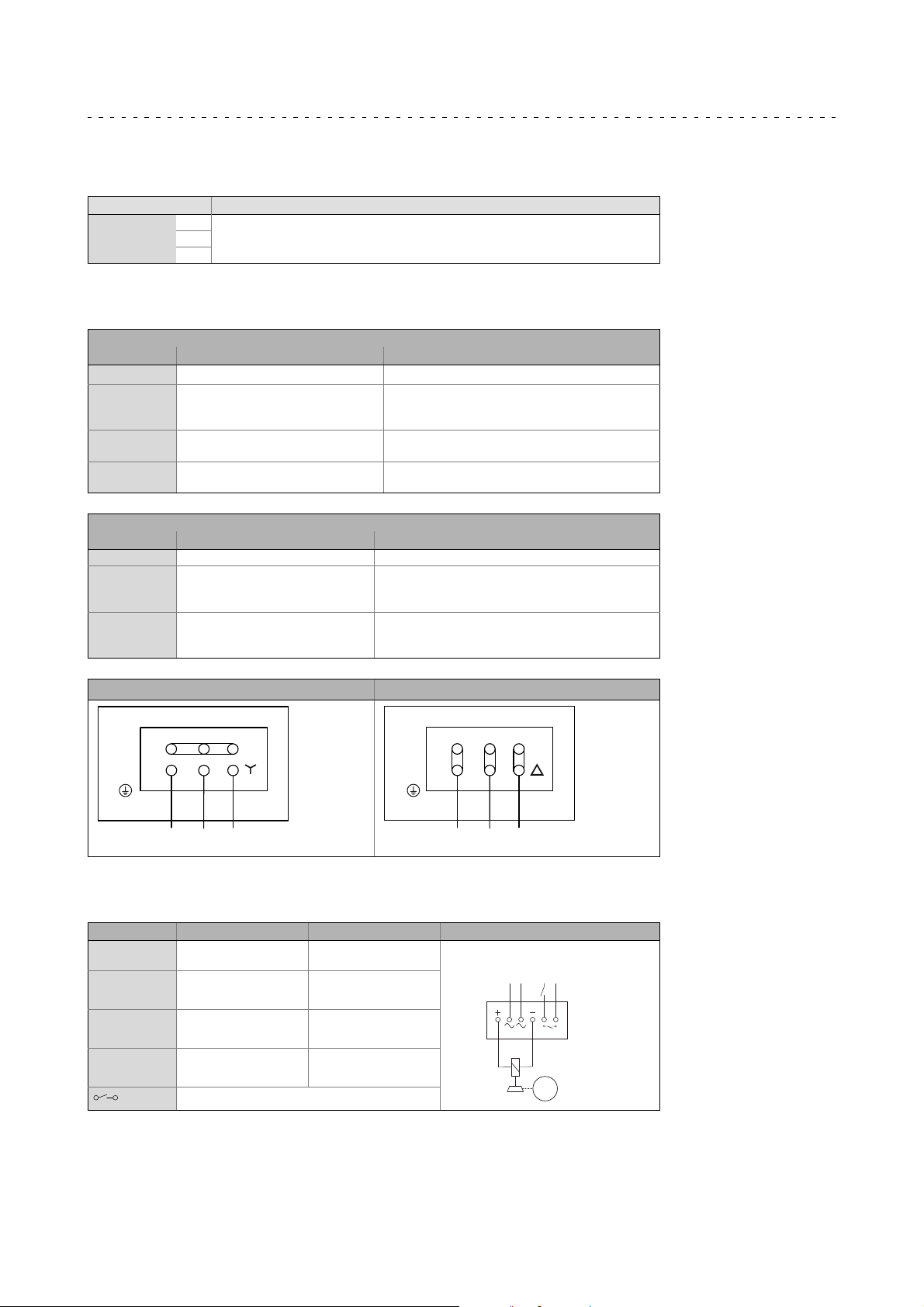
Cable glands for the fan terminal box
Motor type/size Screwed connection
MCA/MQA
20
22
1xM16x1.5
26
6.4.1 Power connections
MCA; MCS, MQA 20...22, MDKS
Contact Name Meaning
U
V
W
TP1
TP2
TB1
TB2
PE PE conductor
U
V
W
TP1
TP2
TB1
TB2
Motor winding phase U
Motor winding phase V
Motor winding phase W
PTC thermistor
Thermostat
Thermal NC contact
Electrical installation
Terminal box
Cable glands for the fan terminal box
6
MCA 26, MQA 26
Contact Name Meaning
PE PE conductor
1
2
3
4
5
6
U1
V1
W1
W2
U2
V2
Start of winding phase U
Start of winding phase V
Start of winding phase W
End of winding phase W
End of winding phase U
End of winding phase V
Star connection Delta connection
(W2)
4
1
L1
(U1)
(U2)
5
2
L2
(V1)
(V2)
6
3
(W1)
L3
PE
(W2)
4
1
L1
(U1)
(U2)
5
2
(V2)
6
3
(V1)
(W1)
L3
L2
PE
6.4.2 Holding brake DC 205 V - connected via rectifier (optionl)
Contact Name Meaning
BA1
BA2
+
-
BD1 (factory-set
wiring)
BD2 (factory-set
wiring)
Switching contact, DC switching
Connection to L1 mains
Connection to N mains
Connection of holding
brake +
Connection of holding
brake -
AC-excited brake (rectifier)
N
L1
M
3~
Lenze • BA 33.0006 • 5.1
33
Page 34
6
Electrical installation
Terminal box
Holding brake DC 24 V (optional)
6.4.3 Holding brake DC 24 V (optional)
Contact Name Meaning
BD1
BD2
BD1
BD2
Holding brake +
Holding brake -
6.4.4 Fan
1-phase
Contact Name Meaning
U1
U2
3-phase
Contact Name Meaning
L1
L2
L3
PE PE conductor
U1
U2
PE PE conductor
U
V
W
Connection to L1 - mains
Connection to N - mains
Connection to L1 mains
Connection to L2 mains
Connection to L3 mains
6.4.5 Feedback system
Resolver
Contact Name Meaning
B1
B2
B3 +VCCENP Supply: electronic nameplate
B4
B5
B6
B7
B8 Not assigned
R1
R2
Incremental encoder / sin/cos absolute value encoder with Hiperface
Contact Name Meaning
B1
B2
B3
B4
B5
B6
B7
B8
B10 Shield Encoder housing shield
R1
R2
+Ref
-Ref
+COS
-COS
+SIN
-SIN
+KTY
-KTY
1) Only for versions with electronic nameplate ENP.
+U
B
GND
A
A
B
B
Z
Z
+KTY
-KTY
Transformer windings
(reference windings)
Stator winding cosine
Stator winding sine
Thermal detector KTY
Supply +
Mass
Track A / + COS
TrackAinverse/ -COS
Track B / + SIN
TrackBinverse/-SIN
Zero track / + RS485
Zero track inverse / - RS485
Thermal detector KTY
1)
34
Lenze • BA 33.0006 • 5.1
Page 35
Sin/cos absolute value encoder with EnDat interface
Contact Name Meaning
B1 +U
B2 GND Mass
B3
B4
B5
B6
B7
B8
B20
B21
B22 UPsensor UPsensor
B23 0 V sensor 0 V sensor
B24 Shield Encoder housing shield
B25 Not assigned
R1
R2
B
A
A
B
B
Data
Data
Cycle
Cycle
+KTY
-KTY
1) Only for versions with electronic nameplate ENP.
Supply + / + VCC ENP
Track A
Track A inverse
Track B
Track B inverse
Data EnDat interface
Data inverse EnDat interface
Clock pulse EnDat interface
Clock pulse inverse EnDat interface
Thermal detector KTY
Electrical installation
6
Terminal box
Feedback system
1)
Lenze • BA 33.0006 • 5.1
35
Page 36
Safety engineering7
7 Safetyengineering
Motor-encoder combinations
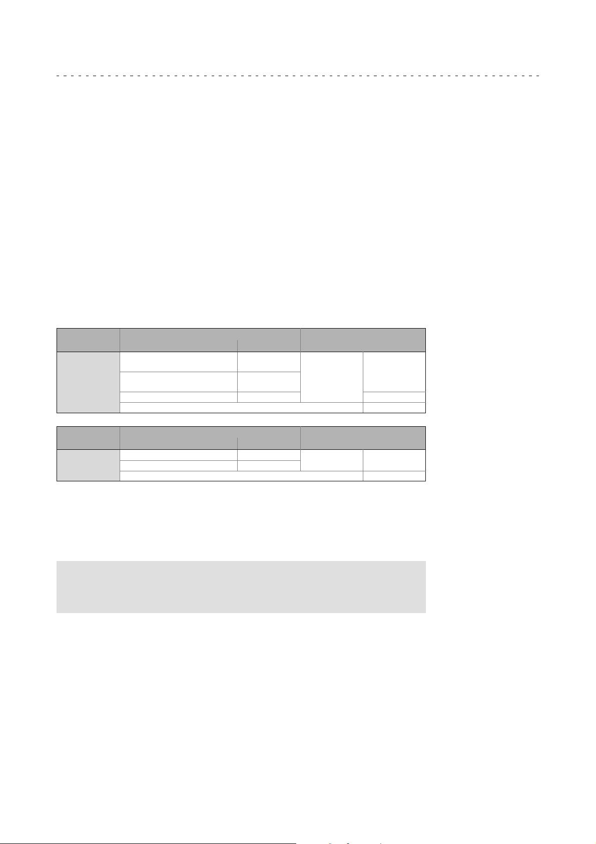
Drive systems with Servo Drives 9400 and safety module SM301 provide
speed-dependent safety functions for safe speed monitoring and/or safe
relative-positionmonitoring. Observe permissiblemotor-encodercombinationsduring
configuration.
• Possible speed-dependent safety functions with safety module SM301:
– Safe stop 1 (SS1)
– Safe operational stop (SOS)
– Safely limited speed (SLS)
– Safe maximum speed (SMS)
– Safe direction (SDI)
– Safe speed monitor (SSM)
– Safely limited increment (SLI)
• Permissible motor-encoder combinations for these functions:
Synchronous
servo motors
MCS 06 ... 19
MDXKS 56 / 71
Asynchronous
servo motors
MCA 10 ... 26
MQA 20 ... 26
Sin/cos absolute value,
single-turn
Sin/cos absolute value,
multi-turn
Resolver RV03 PL e / SIL 3
Sin/cos incremental IG1024-5V-V3
Resolver RV03
Encoder
Type Product key
AS1024-8V-K2
AM1024-8V-K2
Encoder
Type Product key
Safe speed monitoring with
Single-encoder
Two-encoder concept Up to PL e / SIL 3
Safe speed monitoring with
Single-encoder
Two-encoder concept Up to PL e / SIL 3
SM301
concept
SM301
concept
PL d / SIL 2
PL e / SIL 3
A ”two-encoder concept” includes e.g. a resolver as motor encoder and, at the same
time, an absolute value encoder (sin/cos), an incremental encoder (TTL), or digital
encoder (SSI/bus) as position encoder on the machine.
In the case of the ”2-encoder concept”, the achievable risk mitigation (PL/SIL) depends
on the suitability of the encoders used.
Note!
If feedback systems for safety functions are used, the manufacturer’s
documentation must be observed!
36
Lenze • BA 33.0006 • 5.1
Page 37

Commissioning and operation
8 Commissioning andoperation
8.1 Important notes
For trial run without output elements, lock the featherkey. Do not deactivate the
protective devices, not even in a trial run.
Check the correct operation of the brake before commissioning motors with brakes.
8.2 Before switching on
Note!
Before switch-on, you must ensure that the motor starts with the
intended direction of rotation.
Lenze motors rotate CW (looking at the driven shaft) if a clockwise
three-phase field L1 U1, L2 V1, L3 W1 is applied.
8
Important notes
Before initial commissioning, before commissioning after an extended standstill
period, or before commissioning after an overhaul of the motor, the following must be
checked:
• Measure the insulation resistance, in case of values 1kper volt of rated
voltage, dry the winding.
• Have all screwed connections of the mechanical and electrical parts been firmly
tightened?
• Is the unrestricted supply and removal of cooling air ensured?
• Has the PE conductor been connected correctly?
• Have the protective devices against overheating (temperature sensor evaluation)
been activated?
• Is the controller correctly parameterised for the motor?
( Controller operating instructions)
• Are the electrical connections o.k.?
• Does the motor connection have the correct phase sequence?
• Are rotating parts and surfaces which can become very hot protected against
accidental contact?
• Is the contact of good electrical conductivity if a PE connection on the motor
housing is used?
Lenze • BA 33.0006 • 5.1
37
Page 38

8
8.3 Functional test
• Check all functions of the drive after commissioning:
• Direction of rotation of the motor
• Torque behaviour and current consumption
• Function of the feedback system
8.4 During operation
Commissioning and operation
Functional test
– Direction of rotation in the disengaged state (see chapter ”Electrical
connection”).
Stop!
• Fire hazard! Do not clean or spray motors with flammable detergents
or solvents.
• Avoid overheating! Deposits on the drives impede the heat dissipation
required and have to be removed regularly.
Danger!
During operation, motor surfaces must not be touched. According to the
operating status, the surface temperature for motors can be up to 140°C.
For the protection against burn injuries, provide protection against
contact, if necessary. Observe coolingoff times!
During operation, carry out inspections on a regular basis. Pay special attention to:
• Unusual noises
• Oil spots on drive end or leakages
• Irregular running
• Increased vibration
• Loose fixing elements
• Condition of electrical cables
• Speed variations
• Impeded heat dissipation
– Deposits on the drive system and in the cooling channels
– Pollution of the air filter
In case of irregularities or faults: 45.
38
Lenze • BA 33.0006 • 5.1
Page 39

9 Maintenance/repair
9.1 Important notes
Danger!
Hazardous voltage on the power connections even when disconnected
from mains: residual voltage >60 V!
Before working on the power connections, always disconnect the drive
component from the mains and wait until the motor is at standstill.
Verify safe isolation from supply!
Stop!
Repair work or replacement of defective safety encoders must only be
carried out by Lenze service personnel!
Shaft sealing rings and roller bearings have a limited service life.
Maintenance/repair
Important notes
9
Regrease bearingswith relubricating devices while thelowvoltage machine is running.
Only use the grease recommended by the manufacturer.
If thegrease drain holes are sealedwith aplug, (IP54 driveend; IP23 drive and nondrive
end), remove plug before commissioning. Seal bore holes with grease.
9.2 Maintenance intervals
Inspections
• If the machine is exposed to dirt, clean the air channels regularly.
9.2.1 Motor
• Only the bearings and shaft sealing rings become worn.
– Check bearings for noise (after approx. 15,000 h at the latest).
• In order to prevent overheating, remove dirt deposits on the drives regularly.
• We recommend carrying out an inspection after the first 50 operating hours. In
this way, you can detect and correct any irregularities or faults at an early stage.
9.2.2 Safety encoder
After a service life of 10 years, an inspection of the metal elastomer torque plate is
required for the AS1024-8V-K, AS1024-8V-K2; AM1024-8V-K, and AM1024-8V-K2
encoders. Ifno replacement isrequired, an inspection interval ofmax. 5 yearshas to be
observed.
Stop!
Repair work or replacement of defective safety encoders must only be
carried out by Lenze service personnel!
Lenze • BA 33.0006 • 5.1
39
Page 40
9
9.2.3 Holding brake
The brakes need to be checked on a regular basis to ensure safe and trouble-free
operation.
The necessary maintenance intervals primarily depend onthe stressto whichthe brake
is subjected in an application. When a maintenance interval is being calculated, all
causes of wearmust be takeninto account (seenotes ”Wear onspring-applied brakes”).
In the case of brakes which are subjected to low levels of stress, e.g. holdingbrakes with
emergencystop function, regularinspections atafixedtime intervalare recommended.
In order toreduce theamount of workinvolved inmaintenance, perform theinspection
at the same time as other maintenance work carried out cyclically on the machine if
possible.
If thebrakes are not properly serviced,operating faults, productionoutages ordamage
to machinery can occur. A maintenance concept adapted to the operating conditions
andthe stressestowhich thebrakesare subjected musttherefore be drawnupfor every
application. For brakes, the maintenance intervals and servicing work listed in the
following table are necessary.
Maintenance/repair
Maintenance operations
Holding brake
Maintenance interval for holding brake with
emergency stop
At least every 2 years
After 1 million cycles at the latest
Shorter intervals in the case of frequent emergency
stops!
The brakesof theMCA, MCM, MCS, MQA, andMDKS motorscannot be accessed from
theoutside! (Maintenanceworkon the brakesmust be carriedout by LenzeServicestaff
only!)
9.3 Maintenance operations
Maintenance work
Inspection of the brake integrated in the motor:
• Check ventilation function and
activation/deactivation
Stop!
• Make sure that no foreign bodies can enter the inside of the motor!
• Do not remove plugs when voltage is being applied!
Danger!
• Only work on the drive system when it is in a deenergised state!
• Hot motor surfaces of up to 150 °C. Observe cooling times!
• Remove loads acting on motors or secure loads acting on the drive!
9.3.1 Blower
If themotor is equipped with a blower, this blower must becleaned or even replaced at
regular intervals depending on the amount of dust (if necessary, daily).
40
Lenze • BA 33.0006 • 5.1
Page 41
Maintenance/repair
Maintenance operations
Fan with dust protection filter
9.3.2 Fan with dust protection filter
For the motors, dry filters are used.
Note!
The dust protection filter is mounted to the fan unit. Depending on the
amount of dust, the filter must be cleaned completely or replaced at
regular intervals!
Polluted filterssubstantially reduce the amount ofcooling air. This brings abouthigher
winding temperatures, reduces the filters’ service life and may cause damage to the
filters.
When replacing the filters it must be ensured that all covers as well as the filter are fit
tightly, therefore preventingthe occurrenceof leakages fora damagingingress of dust!
Inthecaseofmoist dust,new filtermats must bemounted. Atthe latestwhen the filter
is replaced for the first time it should be checked that the interiorof the motor is clean.
9
9.3.3 Motors with bearing relubricating devices
Under normal operating conditions, the bearings used have a service life of approx.
20.000 operating hours. Ex works the bearings are filled with a high-quality,
heat-resistant roller bearing grease. (The permissible operating temperature range of
the grease used is between -25°C and +120°C).
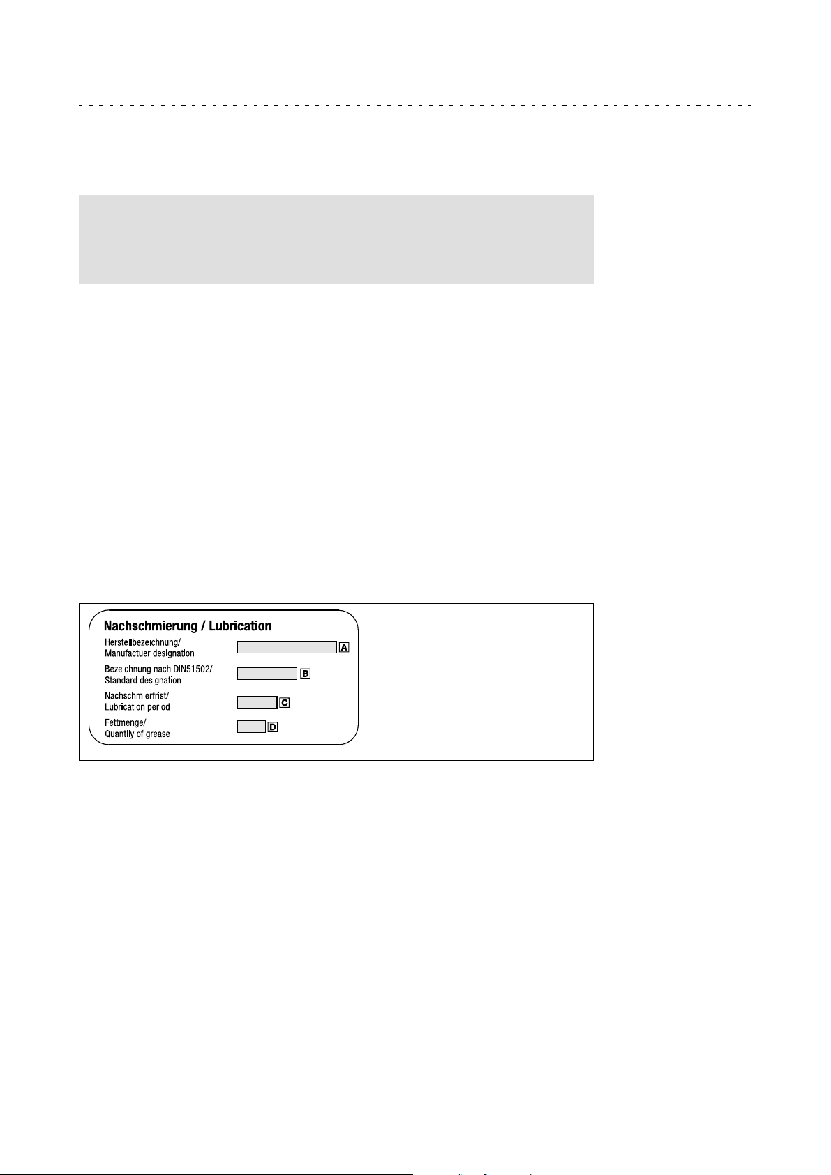
Relubrication period, type of grease and amount of grease are stated on an additional
indicating label on the motor.
Manufacturer designation
Designation of grease type according to
DIN51502
Relubrication period
Amount of grease
Lenze • BA 33.0006 • 5.1
41
Page 42
9
Maintenance/repair
Maintenance operations
Motor plug connection assignment
9.3.4 Motor plug connection assignment
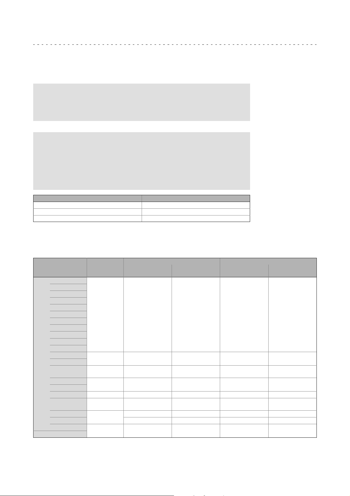
This motor-plug assignment is a rough selection of possible mechanical combinations.
Note!
When making your selection, the motor data and permissible currents of
the cables according to the system cable system manual must be
observed.
Further information is provided in the system cables system manual at:
www.Lenze.de Download Technical documentation
Finding technical documentation
Filter: Type of contents
System manual
Filter: Product
System cable
Connector Connectable cross-section of the motor cable
EWS0001 / EWS1001 1.0 mm2,1.5mm2,2.5mm
EWS0012 / EWS1012 2.5 mm2,4.0mm
EWS0013 / EWS1013 6.0 mm2, 10.0 mm2, 16.0 mm
2
2
2
9.3.5 Power connection cable connectors
Asynchronous servo motors
Motor type Plug size *
Spare part
designation
MCA 10I40- ... S00
13I34- ... Fx0
13I41- ... S00
14L16- ... Fx0
14L20- ... S00
14L35- ... Fx0
14L41- ... S00
17N17- ... Fx0
17N23- ... S00
17N35- ... Fx0
17N41- ... S00
19S17- ... Fx0
19S23- ... S00
19S35- ... Fx0 M40
19S42- ... S00
20X14- ... Fx0
20X29- ... Fxx M40 EWS0013 M03 EWS1013 M06
21X17- ... Fx0 M40
21X25- ... S00
21X35- ... Fx0 EWS0013 M03 EWS1013 M06
21X42- ... S00
MQA 20
M23 EWS0001 M01 EWS1001 M04
M40 EWS0012 M02 EWS1012 M05
EWS0012
EWS0013
M40
M40
M40
EWS0012
EWS0013
EWS0012
EWS0013
EWS0012 M02 EWS1012 M05
EWS0012
EWS0013
Screw plug SpeedTec
Coding in the system
cabletypecode
M02
M03
M02
M03
M02
M03
M02
M03
Spare part
designation
EWS1012
EWS1013
EWS1012
EWS1013
EWS1012
EWS1013
EWS1012
EWS1013
Coding in the system
cabletypecode
M05
M06
M05
M06
M05
M06
M05
M06
42
Lenze • BA 33.0006 • 5.1
Page 43
Synchronous servo motors
Maintenance/repair
Maintenance operations
Cable connectors
9
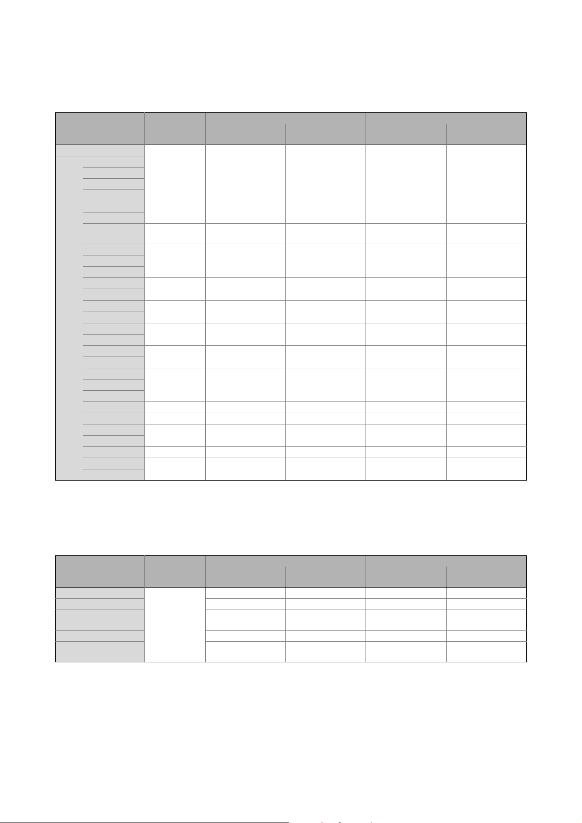
Motor type Plug size *
Spare part
designation
MDSKS 056 - 071
MCM,
06
MCS
09
12
14D
14H12- ... Fx0
14H15- ... S00
14H28- ... Fx0 M40
14H32- ... S00
14L15- ... S00
14L30- ... Fx0
14L32- ... S00
14P11- ... Fx0
S43.14
14P26- ... Fx0
14P32- ... S00
19F12- ... Fx0
19F14- ... S00
19F29- ... Fx0
19F30- ... S00
19J12- ... Fx0
19J14- ... S00 M23 EWS0001 M01 EWS1001 M04
19J29- ... Fx0 M40 EWS0013 M03 EWS1013 M06
19J30- ... S00
19P12- ... Fx0
19P14- ... S00 M23 EWS0001 M01 EWS1001 M04
19P29- ... Fx0
19P30- ... S00
* At times, older documents also stated plug sizes of 1.0 (M23) and 1.5 (M40).
M23 EWS0001 M01 EWS1001 M04
EWS0012
EWS0013
M23 EWS0001 M01 EWS1001 M0414L14- ... Fx0
M40
M23 EWS0001 M01 EWS1001 M04
M40
M23 EWS0001 M01 EWS1001 M04
M40
M40
M40 EWS0013 M03 EWS1013 M06
EWS0012
EWS0013
EWS0012
EWS0013
EWS0012
EWS0013
EWS0012
EWS0013
Screw plug SpeedTec
Coding in the system
cabletypecode
M02
M03
M02
M03
M02
M03
M02
M03
M02
M03
Spare part
designation
EWS1012
EWS1013
EWS1012
EWS1013
EWS1012
EWS1013
EWS1012
EWS1013
EWS1012
EWS1013
Coding in the system
cabletypecode
M05
M06
M05
M06
M05
M06
M05
M06
M05
M06
9.3.6 Cable connectors
Feedback
Type of encoder Plug size *
Spare part
designation
Resolver
Incremental encoder EWS0010 F02 EWS1010 F06
Sin/cos encoder,
Hiperface
Sin/cos encoder, EnDat
Incremental encoder,
Renco R35
Lenze • BA 33.0006 • 5.1
M23
EWS0006 F01 EWS1006 F05
EWS0010 F02 EWS1010 F06
EWS0017 F03 EWS1017 F07
EWS0023 F04 EWS1023 F08
Screw plug SpeedTec
Coding in the system
cabletypecode
Spare part
designation
Coding in the system
cabletypecode
43
Page 44

9
Blower
Maintenance/repair
Repair
Blower Plug size *
Spare part
designation
MDFKS M23 EWS0003 L01 EWS1003 L03
MCS, MCA, MQA M17 EWS0021 L02 EWS1021 L04
Screw plug SpeedTec
Coding in the system
cabletypecode
Spare part
designation
Coding in the system
cabletypecode
9.4 Repair
• We recommend having all repairs carried out by the Lenze customer service.
• In case of version with safety encoder, observe chapter 9.2.2!
44
Lenze • BA 33.0006 • 5.1
Page 45
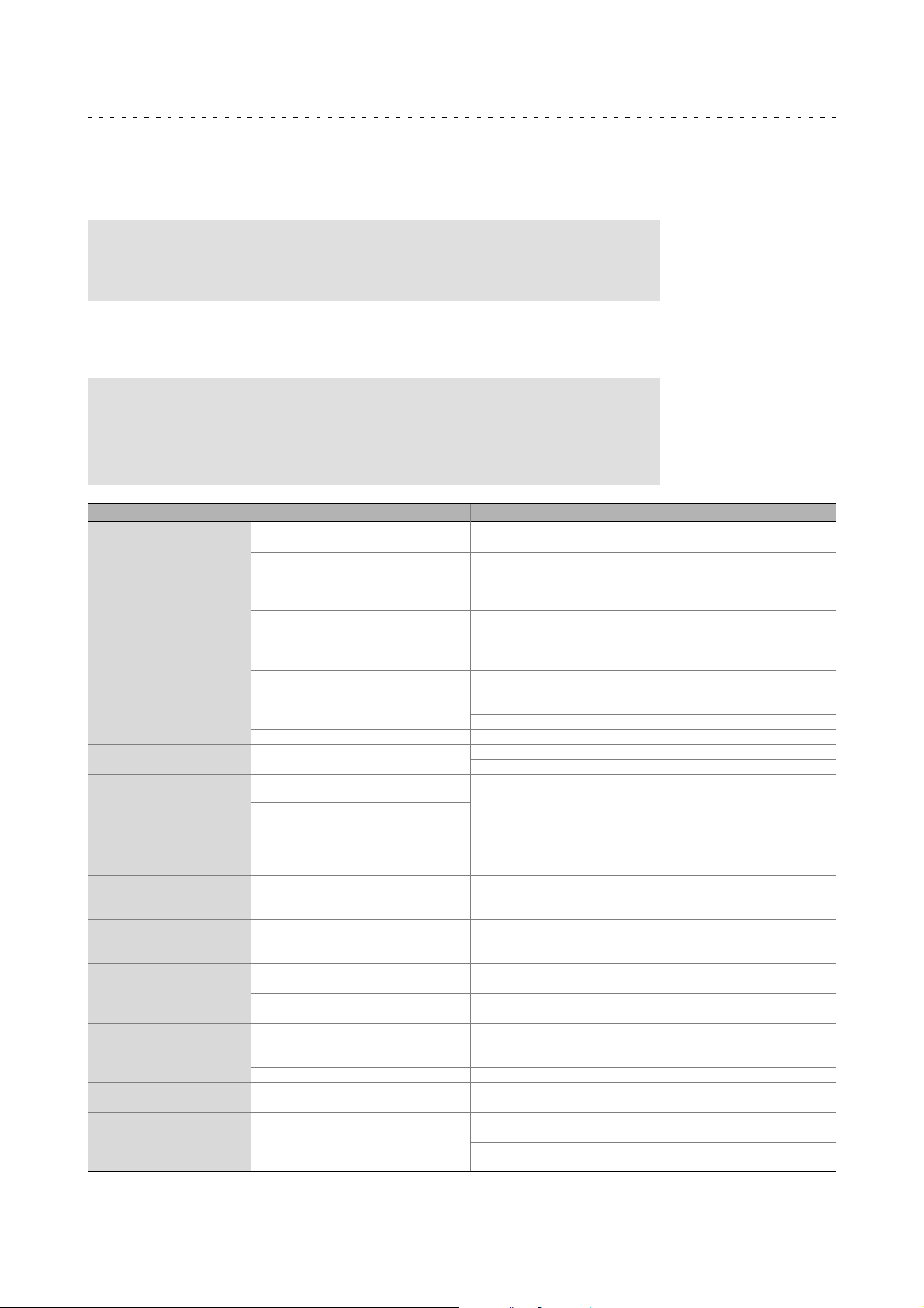
Troubleshooting and fault elimination 10
10 Troubleshootingand faultelimination
If faults occur during operation of the drive system:
• First check the possible causes of malfunction according to the following table.
Note!
Also observe the corresponding chapters in the operating instructions for
the other components of the drive system.
If the fault cannot be remedied using one of the listed measures, please contact the
Lenze Service.
Danger!
• Only work on the drive system when it is in a deenergised state!
• Hot motor surfaces of up to 150 °C. Observe cooling times!
• Remove loads acting on motors or secure loads acting on the drive!
Fault Cause Remedy
Motor too hot
Can only be evaluated by
measuring the surface
temperature:
• Non-ventilated motors
140 °C
• Externally ventilated or
self-ventilated motors
110 °C
Motor suddenly stops and
does not restart
Incorrect direction of
rotation of the motor,
correct display on the
controller
Motor rotates normally but
does not reach the expected
torque
Motor turns in one direction
at maximum speed in an
uncontrolled manner
Motor rotates slowly in one
direction and cannot be
influenced by the controller
Irregular running
Vibrations
Running noises
Surface temperature > 140°C Overload of the drive
Insufficient cooling air, blocked air
ducts.
Preheated cooling air Ensure a sufficient supply of fresh cooling air
Overload, with normal mains voltage
the current is too high and the speed
too low
Rated operating mode exceeded (S1 to
S8 IEC/EN 60034-1)
Loose contact in supply cable
(temporary single-phase operation!)
Fuse has blown (single-phasing!) Replace fuse
Overload of the drive
Heat dissipation impeded by deposits Clean surface and cooling fins of the drives
Overload monitoring of the inverter is
activated
Motor cable polarity is reversed
Polarity of encoder cable reversed
Motor cable interchanged cyclically
Not all motor phases connected
Motor cable interchanged cyclically Check motor connector and, if necessary, correct
Polarity of encoder cable reversed Check encoder connection and, if necessary, correct
Polarity of motor cable and encoder
cable reversed
Insufficient shielding of motor or
resolver cable
Drive controller gain too large Adjust the gains of the controllers (see Drive controller operating
Insufficiently balanced coupling
elements or machine
Inadequate alignment of drive train Realign machine unit, check foundation if necessary
Loose fixing screws Check and tighten screw connections
Foreign particles inside the motor
Bearing damage
Heat dissipation impeded by deposits Clean surface and cooling fins of the drives
Ensure unimpeded circulation of cooling air
Use larger drive (determined by power measurement)
Adjust rated operating mode to the specified operating conditions.
Determination of correct drive by expert or Lenze customer service
Tighten loose contact
Check load and, if necessary, reduce by means of longer ramp-up
times
Check winding temperature
Check controller settings
Reduce load caused by longer acceleration times
Check the polarity and correct
Connect the phases at the motor cable connection correctly
Check the polarity and correct
Checking shielding and earth connection
instructions)
Rebalance
Repair by manufacturer if necessary
Check load and, if necessary, reduce by means of longer ramp-up
times
Check winding temperature
Lenze • BA 33.0006 • 5.1
45
Page 46

Notes
46
Lenze • BA 33.0006 • 5.1
Page 47

Notes
Lenze • BA 33.0006 • 5.1
47
Page 48

© 07/2015 | BA 33.0006 | .R./ |5.1|TD09
Lenze Drives GmbH
Postfach 10 13 52, 31763 Hameln
Breslauer Straße 3, 32699 Extertal
GERMANY
HR Lemgo B 6478
+49 5154 82-0
+49 5154 82-2800
www.lenze.com
Lenze Service GmbH
Breslauer Straße 3, D-32699 Extertal
Germany
0080002446877 (24 h helpline)
+49 5154 82-1112
10987654321
 Loading...