

Lenze M3205S, M3000, M3110S, M3210S, M3210 Installation & Operation Manual
...
MC3000 Series
Installation and Operation Manual
Phone: 800.894.0412 - Fax: 888.723.4773 - Web: www.clrwtr.com - Email: info@clrwtr.com

Phone: 800.894.0412 - Fax: 888.723.4773 - Web: www.clrwtr.com - Email: info@clrwtr.com

1 GENERAL . . . . . . . . . . . . . . . ..... . . . . . . . . . . . . . . . . . . . . . . . . . . . . . . . . . . . . . . . . . . . . . 1
1.1 PRODUCTS COVERED IN THIS MANUAL. . . . . . . . . . . . . . . . . . . . . . . . . . . . . . . . . . 1
1.2 PRODUCT CHANGES . . . . . . . . . . . . . . . . . . . . . . . . . . . . . . . . . . . . . . . . . . . . . . . . . . 1
1.3 WARRANTY . . . . . . . . . . . . . . . . . . . . . . . . . . . . . . . . . . . . . . . . . . . . . . . . . . . . . . . . . . 1
1.4 RECEIVING . . . . . . . . . . . . . . . . . . . . . . . . . . . . . . . . . . . . . . . . . . . . . . . . . . . . . . . . . . 1
1.5 CUSTOMER MODIFICATION . . . . . . . . . . . . . . . . . . . . . . . . . . . . . . . . . . . . . . . . . . . . 1
1.6 SAFETY INFORMATION . . . . . . . . . . . . . . . . . . . . . . . . . . . . . . . . . . . . . . . . . . . . . . . . 1
1.6.1 EXPLOSION PROOF APPLICATIONS . . . . . . . . . . . . . . . . . . . . . . . . . . . . . 2
1.6.2 EN 61800-5-1 COMPLIANCE. . . . . . . . . . . . . . . . . . . . . . . . . . . . . . . . . . . . . 2
1.6.3 PICTOGRAPHS USED IN THESE INSTRUCTIONS. . . . . . . . . . . . . . . . . . . 2
2 MC3000 SPECIFICATIONS . . . . . . . . . . . . . . . . . . . . . . . . . . . . . . . . . . . . . . . . . . . . . . . . . . . 3
3 MC3000 MODEL DESIGNATION CODE . . . . . . . . . . . . . . . . . . . . . . . . . . . . . . . . . . . . . . . . . 4
4 MC3000 DIMENSIONS . . . . . . . . . . . . . . . . . . . . . . . . . . . . . . . . . . . . . . . . . . . . . . . . . . . . . . . 5
4.1 CHASSIS AND TYPE 1 ENCLOSED . . . . . . . . . . . . . . . . . . . . . . . . . . . . . . . . . . . . . . . 5
4.2 TYPE 4, 4X, AND 12 ENCLOSED . . . . . . . . . . . . . . . . . . . . . . . . . . . . . . . . . . . . . . . . . 7
5 MC3000 RATINGS . . . . . . . . . . . . . . . . . . . . . . . . . . . . . . . . . . . . . . . . . . . . . . . . . . . . . . . . . . 9
6 THEORY . . . . . . . . . . . . . . . . . . . . . . . . . . . . . . . . . . . . . . . . . . . . . . . . . . . . . . . . . . . . . . . . . 12
6.1 DESCRIPTION OF AC MOTOR OPERATION. . . . . . . . . . . . . . . . . . . . . . . . . . . . . . . 12
6.2 DRIVE FUNCTION DESCRIPTION . . . . . . . . . . . . . . . . . . . . . . . . . . . . . . . . . . . . . . . 14
6.2.1 DRIVE OPERATION. . . . . . . . . . . . . . . . . . . . . . . . . . . . . . . . . . . . . . . . . . . 14
6.2.2 CIRCUIT DESCRIPTION . . . . . . . . . . . . . . . . . . . . . . . . . . . . . . . . . . . . . . . 15
6.2.3 MC3000 INPUTS AND OUTPUTS. . . . . . . . . . . . . . . . . . . . . . . . . . . . . . . . 15
7 INSTALLATION. . . . . . . . . . . . . . . . . . . . . . . . . . . . . . . . . . . . . . . . . . . . . . . . . . . . . . . . . . . . 16
7.1 INSTALLATION AFTER A LONG PERIOD OF STORAGE . . . . . . . . . . . . . . . . . . . . . 17
7.2 EXPLOSION PROOF APPLICATIONS . . . . . . . . . . . . . . . . . . . . . . . . . . . . . . . . . . . . 17
8 INPUT AC REQUIREMENTS .. . . . . . . . . . . . . . . . . . . . . . . . . . . . . . . . . . . . . . . . . . . . . . . . 18
8.1 INPUT AC POWER REQUIREMENTS. . . . . . . . . . . . . . . . . . . . . . . . . . . . . . . . . . . . . 18
8.1.1 VOLTAGE. . . . . . . . . . . . . . . . . . . . . . . . . . . . . . . . . . . . . . . . . . . . . . . . . . . 18
8.1.2 SUPPLY TRANSFORMER kVA RATINGS . . . . . . . . . . . . . . . . . . . . . . . . . 18
8.2 INPUT FUSING AND DISCONNECT REQUIREMENTS. . . . . . . . . . . . . . . . . . . . . . . 18
9 VOLTAGE SELECTION . . . . . . . . . . . . . . . . . . . . . . . . . . . . . . . . . . . . . . . . . . . . . . . . . . . . . 19
9.1 INPUT VOLTAGE RATINGS . . . . . . . . . . . . . . . . . . . . . . . . . . . . . . . . . . . . . . . . . . . . 19
10 POWER WIRING. . . . . . . . . . . . . . . . . . . . . . . . . . . . . . . . . . . . . . . . . . . . . . . . . . . . . . . . . . . 20
10.1 WIRING FOR SINGLE PHASE OR THREE PHASE INPUT . . . . . . . . . . . . . . . . . . . . 20
11 MC3000 POWER WIRING DIAGRAM . . . . . . . . . . . . . . . . . . . . . . . . . . . . . . . . . . . . . . . . . . 21
12 INITIAL POWER UP .. . . . . . . . . . . . . . . . . . . . . . . . . . . . . . . . . . . . . . . . . . . . . . . . . . . . . . . 22
13 kEYPAD CONTROL . . . . . . . . . . . . . . . . . . . . . . . . . . . . . . . . . . . . . . . . . . . . . . . . . . . . . . . . 24
13.1 kEYPAD FUNCTIONS . . . . . . . . . . . . . . . . . . . . . . . . . . . . . . . . . . . . . . . . . . . . . . . . . 24
13.2 MC3000 DISPLAY . . . . . . . . . . . . . . . . . . . . . . . . . . . . . . . . . . . . . . . . . . . . . . . . . . . . 25
13.2.1 MC3000 DISPLAY IN STOP MODE. . . . . . . . . . . . . . . . . . . . . . . . . . . . . . . 25
13.2.2 MC3000 DISPLAY IN RUN MODE. . . . . . . . . . . . . . . . . . . . . . . . . . . . . . . . 26
13.2.3 MC3000 DISPLAY IN FAULT MODE. . . . . . . . . . . . . . . . . . . . . . . . . . . . . . 27
13.2.4 MC3000 DISPLAY IN AUXILIARY MODE . . . . . . . . . . . . . . . . . . . . . . . . . . 28
CONTENTS
Phone: 800.894.0412 - Fax: 888.723.4773 - Web: www.clrwtr.com - Email: info@clrwtr.com

14 CONTROL WIRING. . . . . . . . . . . . . . . . . . . . . . . . . . . . . . . . . . . . . . . . . . . . . . . . . . . . . . . . . 29
14.1 GENERAL. . . . . . . . . . . . . . . . . . . . . . . . . . . . . . . . . . . . . . . . . . . . . . . . . . . . . . . . . . . 29
14.1.1 kEYPAD CONTROL. . . . . . . . . . . . . . . . . . . . . . . . . . . . . . . . . . . . . . . . . . . 29
14.1.2 CONTROL WIRING VS. POWER WIRING . . . . . . . . . . . . . . . . . . . . . . . . . 29
14.1.3 TB-2: CIRCUIT COMMON . . . . . . . . . . . . . . . . . . . . . . . . . . . . . . . . . . . . . . 29
14.1.4 SURGE SUPPRESSION ON RELAYS . . . . . . . . . . . . . . . . . . . . . . . . . . . . 29
14.2 START/STOP AND SPEED CONTROL. . . . . . . . . . . . . . . . . . . . . . . . . . . . . . . . . . . . 30
14.2.1 REMOTE MODE SELECTION. . . . . . . . . . . . . . . . . . . . . . . . . . . . . . . . . . . 30
14.2.2 TWO-WIRE START/STOP CONTROL. . . . . . . . . . . . . . . . . . . . . . . . . . . . . 30
14.2.3 THREE-WIRE START/STOP CONTROL. . . . . . . . . . . . . . . . . . . . . . . . . . . 30
14.2.4 SPEED REFERENCE SIGNALS . . . . . . . . . . . . . . . . . . . . . . . . . . . . . . . . . 30
14.2.5 SPEED REFERENCE SELECTION. . . . . . . . . . . . . . . . . . . . . . . . . . . . . . . 31
14.2.6 ANALOG OUTPUT SIGNALS . . . . . . . . . . . . . . . . . . . . . . . . . . . . . . . . . . . 32
14.2.7 DRIVE STATUS OUTPUTS . . . . . . . . . . . . . . . . . . . . . . . . . . . . . . . . . . . . . 32
15 MC3000 CONTROL WIRING DIAGRAMS .. . . . . . . . . . . . . . . . . . . . . . . . . . . . . . . . . . . . . . 33
15.1 MC3000 TERMINAL STRIP . . . . . . . . . . . . . . . . . . . . . . . . . . . . . . . . . . . . . . . . . . . . . 33
15.2 TWO-WIRE START/STOP CONTROL. . . . . . . . . . . . . . . . . . . . . . . . . . . . . . . . . . . . . 34
15.3 THREE-WIRE START/STOP CONTROL. . . . . . . . . . . . . . . . . . . . . . . . . . . . . . . . . . . 35
15.4 SPEED POT AND PRESET SPEED CONTROL . . . . . . . . . . . . . . . . . . . . . . . . . . . . . 36
16 PROGRAMMING THE MC3000 DRIVE .. . . . . . . . . . . . . . . . . . . . . . . . . . . . . . . . . . . . . . . . 37
16.1 PROGRAMMING THE PARAMETERS . . . . . . . . . . . . . . . . . . . . . . . . . . . . . . . . . . . . 37
16.2 PARAMETER ACCESS USING SPEED DIAL. . . . . . . . . . . . . . . . . . . . . . . . . . . . . . . 39
17 PARAMETER MENU. . . . . . . . . . . . . . . . . . . . . . . . . . . . . . . . . . . . . . . . . . . . . . . . . . . . . . . . 40
18 DESCRIPTION OF PARAMETERS . . . . . . . . . . . . . . . . . . . . . . . . . . . . . . . . . . . . . . . . . . . . 44
19 MC3000 PID SETPOINT CONTROL. . . . . . . . . . . . . . . . . . . . . . . . . . . . . . . . . . . . . . . . . . . . 67
19.1 FEEDBACk DEVICES . . . . . . . . . . . . . . . . . . . . . . . . . . . . . . . . . . . . . . . . . . . . . . . . . 67
19.2 THE SYSTEM - DIRECT AND REVERSE ACTING. . . . . . . . . . . . . . . . . . . . . . . . . . . 68
19.3 PID CONTROL - DIRECT AND REVERSE ACTING . . . . . . . . . . . . . . . . . . . . . . . . . . 68
19.4 SETPOINT REFERENCE SOURCES . . . . . . . . . . . . . . . . . . . . . . . . . . . . . . . . . . . . . 68
19.5 TUNING THE PID CONTROL . . . . . . . . . . . . . . . . . . . . . . . . . . . . . . . . . . . . . . . . . . . 69
19.6 MC3000 DISPLAY IN PID MODE. . . . . . . . . . . . . . . . . . . . . . . . . . . . . . . . . . . . . . . . . 70
20 TROUBLESHOOTING. . . . . . . . . . . . . . . . . . . . . . . . . . . . . . . . . . . . . . . . . . . . . . . . . . . . . . . 71
21 USER SETTING RECORD . . . . . . . . . . . . . . . . . . . . . . . . . . . . . . . . . . . . . . . . . . . . . . . . . . . 73
CONTENTS
Phone: 800.894.0412 - Fax: 888.723.4773 - Web: www.clrwtr.com - Email: info@clrwtr.com

M301L 1
1 GENERAL
1.1 PRODUCTS COVERED IN THIS MANUAL
This manual covers the Lenze AC Tech MC3000 Variable Frequency Drive.
1.2 PRODUCT CHANGES
Lenze AC Tech Corporation reserves the right to discontinue or make modifications to
the design of its products and manuals without prior notice, and holds no obligation to
make modifications to products sold previously. Lenze AC Tech Corporation also holds
no liability for losses of any kind which may result from this action. Instruction manuals
with the most up-to-date information are available for download from the Lenze
Americas website.
1.3 WARRANTY
Lenze AC Tech Corporation warrants the MC Series AC motor control to be free of defects
in material and workmanship for a period of two years from the date of shipment from
Lenze Americas' factory. An MC Series control, or any component contained therein,
which under normal use, becomes defective within the stated warranty time period, shall
be returned to Lenze AC Tech Corporation, freight prepaid, for examination (contact
Lenze AC Tech Corporation for authorization prior to returning any product). Lenze AC
Tech Corporation reserves the right to make the final determination as to the validity of
a warranty claim, and sole obligation is to repair or replace only components which have
been rendered defective due to faulty material or workmanship. No warranty claim will
be accepted for components which have been damaged due to mishandling, improper
installation, unauthorized repair and/or alteration of the product, operation in excess
of design specifications or other misuse, or improper maintenance. Lenze AC Tech
Corporation makes no warranty that its products are compatible with any other equipment,
or to any specific application, to which they may be applied and shall not be held liable
for any other consequential damage or injury arising from the use of its products.
This warranty is in lieu of all other warranties, expressed or implied. No other person,
firm or corporation is authorized to assume, for Lenze AC Tech Corporation, any
other liability in connection with the demonstration or sale of its products.
1.4 RECEIVING
Inspect all cartons for damage which may have occurred during shipping. Carefully
unpack equipment and inspect thoroughly for damage or shortage. Report any damage
to carrier and/or shortages to supplier. All major components and connections should be
examined for damage and tightness, with special attention given to PC boards, plugs,
knobs and switches.
1.5 CUSTOMER MODIFICATION
Lenze AC Tech Corporation, its sales representatives and distributors, welcome the
opportunity to assist our customers in applying our products. Many customizing options are
available to aid in this function. Lenze AC Tech Corporation cannot assume responsibility
for any modifications not authorized by its engineering department.
1.6 SAFETY INFORMATION
Some parts of Lenze AC Tech controllers can be electrically live and some surfaces can
be hot. Non-authorized removal of the required cover, inappropriate use, and incorrect
installation or operation creates the risk of severe injury to personnel and/or damage to
equipment. All operations concerning transport, installation, and commissioning as well
as maintenance must be carried out by qualified, skilled personnel who are familiar with
the installation, assembly, commissioning, and operation of variable frequency drives
and the application for which it is being used.
Phone: 800.894.0412 - Fax: 888.723.4773 - Web: www.clrwtr.com - Email: info@clrwtr.com
2 M301L
1.6.1 EXPLOSION PROOF APPLICATIONS
Explosion proof motors that are not rated for inverter use lose their certification when
used for variable speed. Due to the many areas of liability that may be encountered when
dealing with these applications, the following statement of policy applies:
Lenze AC Tech Corporation inverter products are sold with no warranty of fitness for a
particular purpose or warranty of suitability for use with explosion proof motors. Lenze
AC Tech Corporation accepts no responsibility for any direct, incidental or consequential
loss, cost or damage that may arise through the use of AC inverter products in these
applications. The purchaser expressly agrees to assume all risk of any loss, cost or
damage that may arise from such application.
1.6.2 EN 61800-5-1 COMPLIANCE
WARNING!
This product can cause a d.c. current in the protective earthing (PE) conductor.
Where a residual current-operated (RCD) or monitoring (RCM) device is used
for protection in case of direct or indirect contact, only an RCD or RCM Type B is
allowed on the supply side of this product.
WARNING!
Leakage Current may exceed 3.5mA AC. The minimum size of the protective
earth (PE) conductor shall comply with local safety regulations for high leakage
current equipment.
DANGER! Hazard of Electric Shock
Capacitors retain charge for approximately 180 seconds after power is removed.
Allow at least 3 minutes for discharge of residual charge before touching the
drive.
NOTE
Control terminals provide basic isolation (insulation per EN 61800-5-1, for up to
300V to ground). Protection against contact can only be ensured by additional
measures (e.g. supplemental insulation).
WARNING!
In a domestic environment this product may cause radio interference in which
case supplementary mitigation measures may be required.
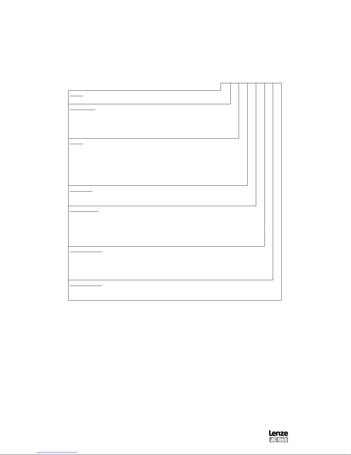
1.6.3 PICTOGRAPHS USED IN THESE INSTRUCTIONS
The safety information provided in this Installation and Operating manual includes a visual
icon, a bold signal word and a description.
Signal Word! (characterizes the severity of the danger)
Text (describes the danger and informs on how to proceed)
Icon Signal Word Meaning Consequences if ignored
DANGER!
Hazardous electrical voltage Death or severe injuries.
WARNING!
Potential, very hazardous situations
for persons near machinery.
Risk of severe injury to personnel
and/or damage to equipment.
STOP!
Potential damage to material and
equipment.
Damage to the controller/drive or
its environment.
NOTE
Designates a general, useful note. None.
If observed, then using the
controller is made easier.
Phone: 800.894.0412 - Fax: 888.723.4773 - Web: www.clrwtr.com - Email: info@clrwtr.com

M301L 3
2 MC3000 SPECIFICATIONS
Storage Temperature -20 to 70 C
Ambient Operating Temperature Chassis -10 to 55 C
(With 2.5, 6, and 8 kHz carrier, Type 1 (IP 31) -10 to 50 C
derate for higher carriers) Type 4 (IP 65) -10 to 40 C
Type 12 (IP 54) -10 to 40 C
Ambient Humidity Less than 95% (non-condensing)
Altitude 3300 feet (1000 m) above sea level
without derating
Input Line Voltages 240/120 Vac, 240/200 Vac,
480/400 Vac, and 590/480 Vac
Input Voltage Tolerance +10%, -15%
Input Frequency Tolerance 48 to 62 Hz
Output Wave Form Sine Coded PWM
Output Frequency 0-120 Hz
Carrier Frequency 2.5 kHz to 14 kHz
Frequency Stability +0.00006% / C
Service Factor 1.00
Efficiency > 97% throughout speed range
Power Factor (displacement) > 0.96
Overload Current Capacity 150% of output rating for 60 seconds
180% of output rating for 30 seconds
Speed Reference Follower 0-10 VDC, 4-20 mA
Control Voltage 15 VDC
Analog Outputs 0 - 10 VDC, or 2 - 10 VDC
Proportional to speed and load
Digital Outputs
Form C relay: 2 A at 28 VDC or 120 Vac
Open-collector outputs: 40 mA at 30 VDC
Phone: 800.894.0412 - Fax: 888.723.4773 - Web: www.clrwtr.com - Email: info@clrwtr.com
4 M301L
3 MC3000 MODEL DESIGNATION CODE
The model number of an MC3000 Series drive gives a full description of the basic drive
unit (see example below).
EXAMPLE: M3450BP
(MC3000, 480 Vac, 5 HP, Type 1 Enclosure, with a Remote keypad Assembly)
M3 4 50 B P
Series:
M3 = M3000 Series Variable Speed AC Motor Drive
Input Voltage:
1 = 240/120 Vac (For 110, 115, 120, 230 and 240 Vac; 50 or 60 Hz)
2 = 240/200 Vac (For 208, 230, and 240 Vac; 50 or 60 Hz)
4 = 480/400 Vac (For 380, 415, 440, 460 and 480 Vac; 50 or 60 Hz)
5 = 590/480 Vac (For 440, 460, 480, 575 and 600 Vac; 50 or 60 Hz)
Rating:
03 = ¼ HP (0.18 kW) 50 / 51 = 5 HP (3.7 kW) 300 = 30 HP (22 kW)
05 = ½ HP (0.37 kW) 75 = 7½ HP (5.5 kW) 400 = 40 HP (30 kW)
10 = 1 HP (0.75 kW) 100 = 10 HP (7.5 kW) 500 = 50 HP (37.5 kW)
15 = 1½ HP (1.1 kW) 150 = 15 HP (11 kW) 600 = 60 HP (45 kW)
20 = 2 HP (1.5 kW) 200 = 20 HP (15 kW)
30 = 3 HP (2.2 kW) 250 = 25 HP (18.5 kW)
Input Phase:
S = Single phase input only.
No character indicates three phase input only
Enclosure Type:
A = Chassis - Open Enclosure with Cover Removed
B = NEMA 1 - General Purpose, vented
C = NEMA 4 - Water-tight and Dust-tight
D = NEMA 12 - Oil-tight and Dust-tight
E = NEMA 4X - Water-tight, Dust-tight, and Corrosion Resistant (Stainless Steel)
Standard Options:
H = Additional Form C Relay circuit board
J = Dynamic Braking circuit board
K = Dynamic Braking & Additional Form C Relay board (not available on all HP sizes - consult factory)
No character when this type of option is not specified
Interface Options:
P = Remote keypad assembly
No character when this type of option is not specified
Phone: 800.894.0412 - Fax: 888.723.4773 - Web: www.clrwtr.com - Email: info@clrwtr.com
M301L 5
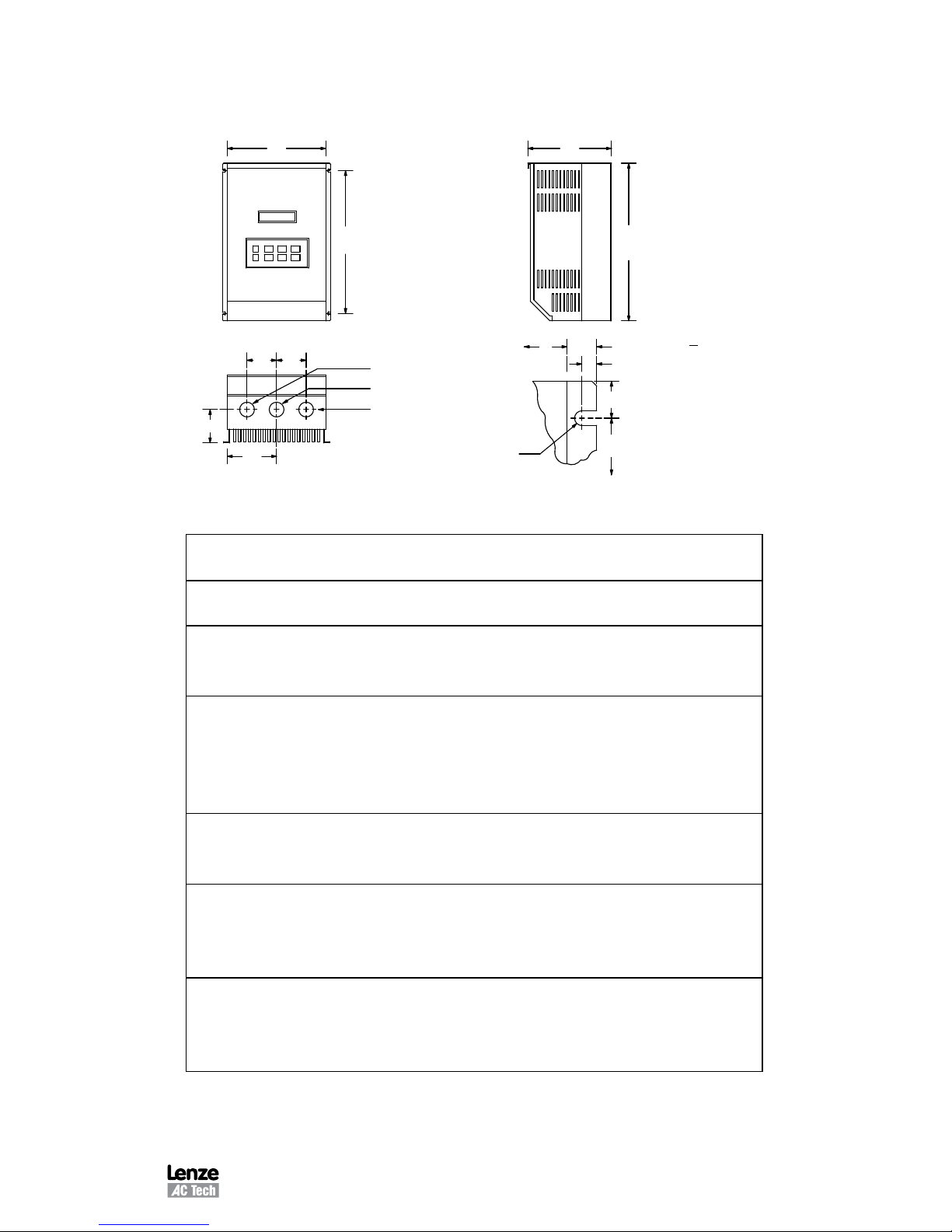
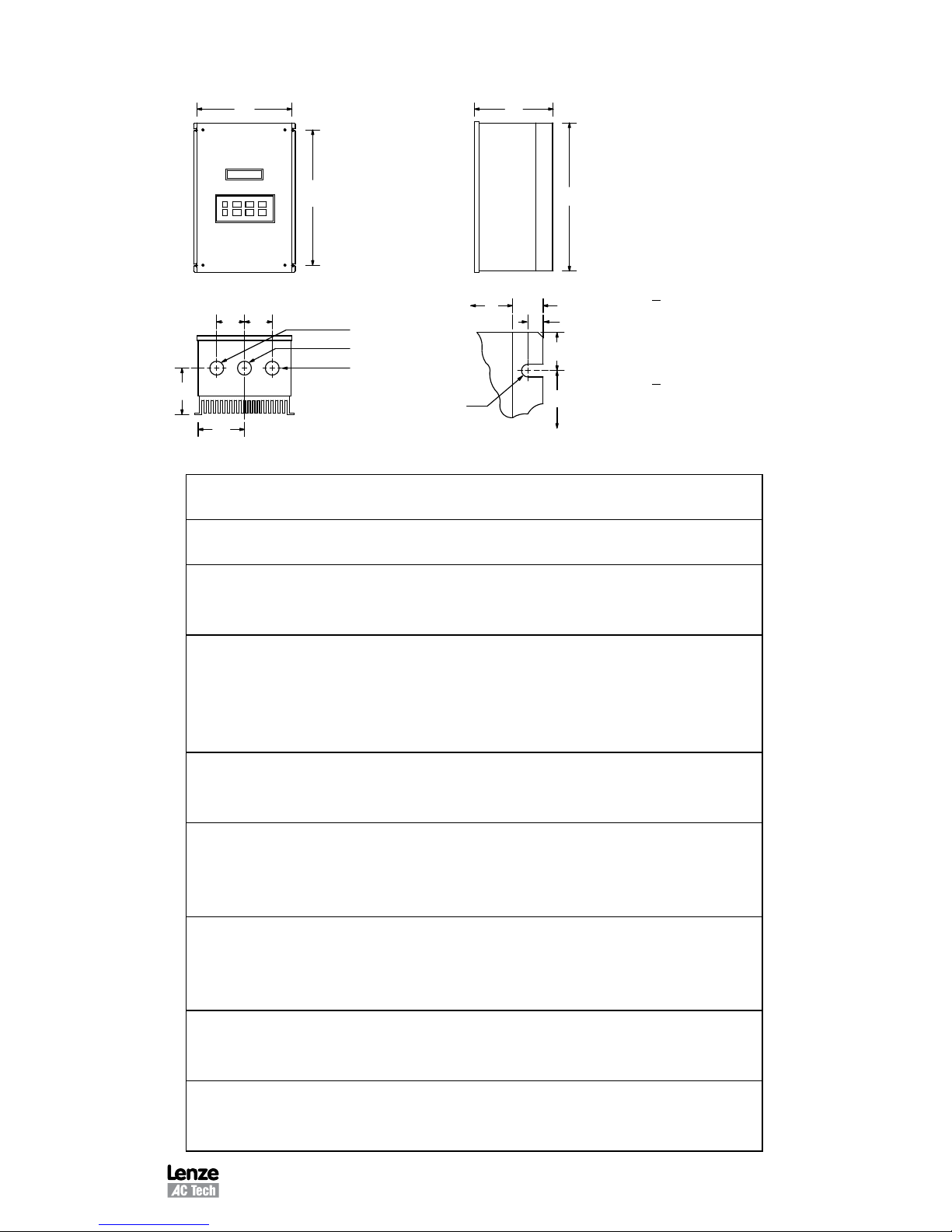
4 MC3000 DIMENSIONS
4.1 CHASSIS AND TYPE 1 ENCLOSED
D
H
V
1.00"
R
T
Mounting Tab Detail
Dia. Slot
R
W
P
N
Q Q
S Dia.
S Dia.
Conduit Holes:
0.88" Dia.
W
U
IF W < 7.86"
T = 0.20"
U = 0.34"
V = 0.19"
IF W = 10.26"
T = 0.28"
U = 0.44"
V = 0.24"
HP
(kW)
INPUT
VOLTAGE MODEL H W D N P Q R S
0.25
(0.18)
240 / 120 M3103S 7.50 4.70 3.33 2.35 1.60 1.37 5.50 0.88
0.5
(0.37)
240 / 120 M3105S 7.50 6.12 3.63 3.77 1.80 1.37 5.50 0.88
240 M3205S 7.50 4.70 3.63 2.35 1.90 1.37 5.50 0.88
240/200 M3205 7.50 4.70 3.63 2.35 1.90 1.37 5.50 0.88
1
(0.75)
240 / 120 M3110S 7.50 6.12 4.22 3.77 2.40 1.37 5.50 0.88
240 M3210S 7.50 4.70 4.33 2.35 2.60 1.37 5.50 0.88
240 / 200 M3210 7.50 4.70 4.33 2.35 2.60 1.37 5.50 0.88
480 / 400 M3410 7.50 4.70 3.63 2.35 1.90 1.37 5.50 0.88
590 M3510 7.50 4.70 3.63 2.35 1.90 1.37 5.50 0.88
1.5
(1.1)
240/120 M3115S 7.50 6.12 4.22 3.77 2.40 1.37 5.50 0.88
240 M3215S 7.50 6.12 4.22 3.77 2.40 1.37 5.50 0.88
240/200 M3215 7.50 4.70 4.33 2.35 2.60 1.37 5.50 0.88
2
(1.5)
240 M3220S 7.50 6.12 5.12 3.77 3.30 1.37 5.50 0.88
240 / 200 M3220 7.50 6.12 5.12 3.77 3.30 1.37 5.50 0.88
480/400 M3420 7.50 6.12 4.22 3.77 2.40 1.37 5.50 0.88
590 M3520 7.50 6.12 4.22 3.77 2.40 1.37 5.50 0.88
3
(2.2)
240 M3230S 7.50 6.12 5.12 3.77 3.30 1.37 5.50 0.88
240 / 200 M3230 7.50 6.12 5.12 3.77 3.30 1.37 5.50 0.88
480 / 400 M3430 7.50 6.12 5.12 3.77 3.30 1.37 5.50 0.88
590 M3530 7.50 6.12 5.12 3.77 3.30 1.37 5.50 0.88
Phone: 800.894.0412 - Fax: 888.723.4773 - Web: www.clrwtr.com - Email: info@clrwtr.com

6 M301L
HP
(kW)
INPUT
VOLTAGE MODEL H W D N P Q R S
5
(3.7)
240 / 200 M3250 7.88 7.86 5.94 5.13 3.95 1.50 5.88 1.13
480 / 400 M3450 7.50 6.12 5.12 3.77 3.30 1.37 5.50 0.88
590 M3551 7.88 7.86 5.94 5.13 3.95 1.50 5.88 1.13
7.5
(5.5)
240 / 200 M3275 9.38 7.86 6.84 3.93 4.19 2.00 5.88 1.13
480 / 400 M3475 9.38 7.86 6.25 5.13 3.95 1.50 7.38 1.13
590 M3575 9.38 7.86 6.25 5.13 3.95 1.50 7.38 1.13
10
(7.5)
240 / 200 M32100 11.25 7.86 6.84 3.93 4.19 2.00 7.75 1.38
480 / 400 M34100 9.38 7.86 6.84 3.93 4.19 2.00 5.88 1.13
590 M35100 9.38 7.86 7.40 3.93 4.19 2.00 5.88 1.13
15
(11)
240/200 M32150 12.75 7.86 6.84 3.93 4.19 2.00 9.25 1.38
480/400 M34150 11.25 7.86 6.84 3.93 4.19 2.00 7.75 1.38
590 M35150 12.75 7.86 6.84 3.93 4.19 2.00 9.25 1.38
20
(15)
240 / 200 M32200 12.75 10.26 7.74 5.13 5.00 2.50 9.25 1.38
480/400 M34200 12.75 7.86 6.84 3.93 4.19 2.00 9.25 1.38
590 M35200 12.75 7.86 7.40 3.93 4.19 2.00 9.25 1.38
25
(18.5)
240 / 200 M32250 15.75 10.26 8.35 5.13 5.00 2.50 12.25 1.38
480/400 M34250 12.75 10.26 7.74 5.13 5.00 2.50 9.25 1.38
590 M35250 12.75 10.26 7.74 5.13 5.00 2.50 9.25 1.38
30
(22)
240 / 200 M32300 15.75 10.26 8.35 5.13 5.00 2.50 12.25 1.38
480/400 M34300 12.75 10.26 7.74 5.13 5.00 2.50 9.25 1.38
590 M35300 12.75 10.26 8.25 5.13 5.00 2.50 9.25 1.38
40
(30)
480/400 M34400 15.75 10.26 8.35 5.13 5.00 2.50 12.25 1.38
590 M35400 15.75 10.26 8.35 5.13 5.00 2.50 12.25 1.38
50
(37.5)
480/400 M34500 19.75 10.26 8.55 5.13 5.75 2.50 16.25 1.75
590 M35500 19.75 10.26 8.55 5.13 5.75 2.50 16.25 1.75
60
(45)
480/400 M34600 19.75 10.26 8.55 5.13 5.75 2.50 16.25 1.75
590 M35600 19.75 10.26 8.55 5.13 5.75 2.50 16.25 1.75
DIMENSIONS - CHASSIS AND TYPE 1 ENCLOSED (continued)
Phone: 800.894.0412 - Fax: 888.723.4773 - Web: www.clrwtr.com - Email: info@clrwtr.com
M301L 7
4.2 TYPE 4, 4X, AND 12 ENCLOSED
1.00"
W
H
R
T
D
Mounting Tab Detail
V
Dia. Slot
Conduit Holes:
S Dia.
0.88" Dia.
S Dia.
N
P
Q
Q
R
W
U
IF W < 7.86"
T = 0.20"
U = 0.34"
V = 0.19"
IF W > 10.26"
T = 0.28"
U = 0.44"
V = 0.24"
HP
(kW)
INPUT
VOLTAGE
MODEL H W D N P Q R S
0.25
(0.18)
240 / 120 M3103S 7.88 6.12 3.63 3.06 2.00 1.37 5.88 0.88
0.5
(0.37)
240 / 120 M3105S 7.88 7.86 3.75 4.80 2.10 1.37 5.88 0.88
240 M3205S 7.88 6.12 4.35 3.06 2.70 1.37 5.88 0.88
240/200 M3205 7.88 6.12 4.35 3.06 2.70 1.37 5.88 0.88
1
(0.75)
240 / 120 M3110S 7.88 7.86 4.90 4.80 3.25 1.37 5.88 0.88
240 M3210S 7.88 6.12 4.35 3.06 2.70 1.37 5.88 0.88
240 / 200 M3210 7.88 6.12 4.35 3.06 2.70 1.37 5.88 0.88
480 / 400 M3410 7.88 6.12 4.35 3.06 2.70 1.37 5.88 0.88
590 M3510 7.88 6.12 4.35 3.06 2.70 1.37 5.88 0.88
1.5
(1.1)
240/120 M3115S 7.88 7.86 4.90 4.80 3.25 1.37 5.88 0.88
240 M3215S 7.88 7.86 4.90 4.80 3.25 1.37 5.88 0.88
240/200 M3215 7.88 6.12 5.25 3.06 3.60 1.37 5.88 0.88
2
(1.5)
240 M3220S 7.88 7.86 4.90 4.80 3.25 1.37 5.88 0.88
240 / 200 M3220 7.88 7.86 4.90 4.80 3.25 1.37 5.88 0.88
480/400 M3420 7.88 7.86 4.90 4.80 3.25 1.37 5.88 0.88
590 M3520 7.88 7.86 4.90 4.80 3.25 1.37 5.88 0.88
3
(2.2)
240 M3230S 7.88 7.86 5.90 4.80 4.25 1.37 5.88 0.88
240 / 200 M3230 7.88 7.86 5.90 4.80 4.25 1.37 5.88 0.88
480 / 400 M3430 7.88 7.86 4.90 4.80 3.25 1.37 5.88 0.88
590 M3530 7.88 7.86 4.90 4.80 3.25 1.37 5.88 0.88
5
(3.7)
240 / 200 M3250 9.75 10.26 7.20 5.13 5.25 2.00 7.75 1.13
480 / 400 M3450 7.88 7.86 5.90 4.80 4.25 1.37 5.88 0.88
590 M3550 7.88 7.86 5.90 4.80 4.25 1.37 5.88 0.88
7.5
(5.5)
240 / 200 M3275 11.75 10.26 8.35 5.13 5.75 2.00 9.75 1.13
480 / 400 M3475 9.75 10.26 7.20 5.13 5.25 2.00 7.75 1.13
590 M3575 9.75 10.26 7.20 5.13 5.25 2.00 7.75 1.13
Phone: 800.894.0412 - Fax: 888.723.4773 - Web: www.clrwtr.com - Email: info@clrwtr.com

8 M301L
HP
(kW)
INPUT
VOLTAGE
MODEL H W D N P Q R S
10
(7.5)
240 / 200 M32100 13.75 10.26 8.35 5.13 5.75 2.00 11.75 1.38
480 / 400 M34100 11.75 10.26 8.35 5.13 5.75 2.00 9.75 1.13
590 M35100 11.75 10.26 8.35 5.13 5.75 2.00 9.75 1.13
15
(11)
240/200 M32150 15.75 10.26 8.35 5.13 5.75 2.00 13.75 1.38
480/400 M34150 13.75 10.26 8.35 5.13 5.75 2.00 11.75 1.38
590 M35150 13.75 10.26 8.35 5.13 5.75 2.00 11.75 1.38
20
(15)
240 / 200 M32200* 15.75 10.26 8.35 5.13 5.75 2.00 11.75 1.38
480/400 M34200 15.75 10.26 8.35 5.13 5.75 2.00 13.75 1.38
590 M35200 15.75 10.26 8.35 5.13 5.75 2.00 13.75 1.38
25
(18.5)
240 / 200 M32250* 20.25 10.26 8.35 5.13 5.75 2.00 16.25 1.38
480/400 M34250* 15.75 10.26 8.35 5.13 5.75 2.00 11.75 1.38
590 M35250* 15.75 10.26 8.35 5.13 5.75 2.00 11.75 1.38
30
(22)
240 / 200 M32300* 20.25 10.26 8.35 5.13 5.75 2.00 16.25 1.38
480/400 M34300* 15.75 10.26 8.35 5.13 5.75 2.00 11.75 1.38
590 M35300* 15.75 10.26 8.35 5.13 5.75 2.00 11.75 1.38
40
(30)
480/400 M34400* 20.25 10.26 8.35 5.13 5.75 2.00 16.25 1.38
590 M35400* 20.25 10.26 8.35 5.13 5.75 2.00 16.25 1.38
50
(37.5)
480/400 M34500* 21.00 13.72 8.35 5.13 6.10 2.00 16.25 1.38
590 M35500* 21.00 13.72 8.35 5.13 6.10 2.00 16.25 1.38
60
(45)
480/400 M34600* 21.00 13.72 8.35 5.13 6.10 2.00 16.25 1.38
590 M35600* 21.00 13.72 8.35 5.13 6.10 2.00 16.25 1.38
*Models available in NEMA 12 only
DIMENSIONS - TYPE 4, 4X, AND 12 ENCLOSED (continued)
Phone: 800.894.0412 - Fax: 888.723.4773 - Web: www.clrwtr.com - Email: info@clrwtr.com
M301L 9
5 MC3000 RATINGS
The following tables indicate the input and output ratings of the MC3000 Series drive.
NOTE: The output current ratings are based on operation at carrier frequencies of 8 kHz
and below. At full ambient temperature, operation at carrier frequencies above
8 kHz requires derating the drive by multiplying the output current rating by the
following factors: 0.94 at 10 kHz, 0.89 at 12 kHz, and 0.83 at 14 kHz. Refer to
Parameter 23 - CARRIER in Section 18 - DESCRIPTION OF PARAMETERS.
M3100 SERIES RATINGS
MODEL
INPUT OUTPUT
(200/240 Vac, 50 - 60 Hz) (0 - 200/230 Vac)
MODEL
NUMBER
1
FOR MOTORS
RATED
INPUT
PHASE
NOMINAL
CURRENT
2
(AMPS)
POWER
(KVA)
NOMINAL
CURRENT
(AMPS)
POWER
(KVA)
HP kW
M3103S 0.25 0.18 1 6.0 / 3.0 0.7 1.4 0.56
M3105S 0.5 0.37 1 9.2 / 4.6 1.1 2.2 0.88
M3110S 1 0.75 1 16.2 / 8.1 1.9 4.0 1.6
M3115S 1.5 1.1 1 21 / 10.4 2.5 5.2 2.1
1
Refer to Section 3 for model number breakdown.
2
Refer to Section 8 for recommended fuse type.
M3200 SERIES RATINGS
MODEL
INPUT OUTPUT
(200/240 Vac, 50 - 60 Hz) (0 - 200/230 Vac)
MODEL
NUMBER
1
FOR MOTORS
RATED
INPUT
PHASE
NOMINAL
CURRENT
2
(AMPS)
POWER
(KVA)
NOMINAL
CURRENT
(AMPS)
POWER
(KVA)
HP kW
M3205S 0.5 0.37 1 5.8 / 5.0 1.2 2.5 / 2.2 0.9
M3205 0.5 0.37 3 3.1 / 2.7 1.1 2.5 / 2.2 0.9
M3210S 1 0.75 1 10.3 / 9.0 2.2 4.6 / 4.0 1.6
M3210 1 0.75 3 5.5 / 4.8 2.0 4.6 / 4.0 1.6
M3215S 1.5 1.1 1 13.3 / 11.6 2.8 6.0 / 5.2 2.1
M3215 1.5 1.1 3 7.1 / 6.2 2.6 6.0 / 5.2 2.1
M3220S 2 1.5 1 17.1 / 14.9 3.6 7.8 / 6.8 2.7
M3220 2 1.5 3 9.3 / 8.1 3.4 7.8 / 6.8 2.7
M3230S 3 2.2 1 24 / 21 5.0 11.0 / 9.6 3.8
M3230 3 2.2 3 13.0 / 11.3 4.7 11.0 / 9.6 3.8
M3250 5 3.7 3 20 / 17.7 7.4 17.5 / 15.2 6.1
M3275 7.5 5.5 3 30 / 26 10.6 25 / 22 8.8
M32100 10 7.5 3 37 / 32 13.2 32 / 28 11.2
M32150 15 11 3 55 / 48 19.8 48 / 42 16.7
M32200 20 15 3 70 / 61 25.3 62 / 54 21.5
M32250 25 18.5 3 89 / 77 32.0 78 / 68 27.1
M32300 30 22 3 104 / 90 37.6 92 / 80 31.9
1
Refer to Section 3 for model number breakdown.
2
Refer to Section 8 for recommended fuse type.
Phone: 800.894.0412 - Fax: 888.723.4773 - Web: www.clrwtr.com - Email: info@clrwtr.com

10 M301L
M3400 SERIES RATINGS
MODEL
INPUT OUTPUT
(400/480 Vac, 50 - 60 Hz) (0 - 400/460 Vac)
MODEL
NUMBER
1
FOR MOTORS
RATED
INPUT
PHASE
NOMINAL
CURRENT
2
(AMPS)
POWER
(KVA)
NOMINAL
CURRENT
(AMPS)
POWER
(KVA)
HP kW
M3410 1 0.75 3 2.8 / 2.4 2.0 2.3 / 2.0 1.6
M3420 2 1.5 3 4.7 / 4.1 3.4 3.9 / 3.4 2.7
M3430 3 2.2 3 6.6 / 5.7 4.7 5.5 / 4.8 3.8
M3450 5 3.7 3 10.2 / 8.9 7.3 8.7 / 7.6 6.1
M3475 7.5 5.5 3 14.7 / 12.8 10.6 12.6 / 11.0 8.8
M34100 10 7.5 3 18.3 / 15.9 13.2 16.0 / 14.0 11.2
M34150 15 11 3 28 / 24 19.8 24 / 21 16.7
M34200 20 15 3 36 / 31 25.3 31 / 27 21.5
M34250 25 18.5 3 44 / 38 31.9 39 / 34 27.1
M34300 30 22 3 52 / 45 37.6 46 / 40 31.9
M34400 40 30 3 68 / 59 49.0 60 / 52 41.4
M34500 50 37.5 3 85 / 74 61.5 75 / 65 51.8
M34600 60 45 3 100 / 87 72.3 88 / 77 61.3
1
Refer to Section 3 for model number breakdown.
2
Refer to Section 8 for recommended fuse type.
Phone: 800.894.0412 - Fax: 888.723.4773 - Web: www.clrwtr.com - Email: info@clrwtr.com

M301L 11
M3500 SERIES RATINGS
MODEL
INPUT OUTPUT
(480/590 Vac, 50 - 60 Hz) (0 - 460/575 Vac)
MODEL
NUMBER
1
FOR MOTORS
RATED
INPUT
PHASE
NOMINAL
CURRENT
2
(AMPS)
POWER
(KVA)
NOMINAL
CURRENT
(AMPS)
POWER
(KVA)
HP kW
M3510 1 0.75 3 1.9 / 1.9 1.9 1.6 / 1.6 1.6
M3520 2 1.5 3 3.3 / 3.3 3.4 2.7 / 2.7 2.7
M3530 3 2.2 3 4.6 / 4.6 4.7 3.9 / 3.9 3.9
M3550/51 5 3.7 3 7.1 / 7.1 7.3 6.1 / 6.1 6.1
M3575 7.5 5.5 3 10.5 / 10.5 10.7 9.0 / 9.0 8.8
M35100 10 7.5 3 12.5 / 12.5 12.8 11.0 / 11.0 11.0
M35150 15 11 3 19.3 / 19.3 19.7 17.0 / 17.0 16.9
M35200 20 15 3 25 / 25 25.4 22 / 22 21.5
M35250 25 18.5 3 31 / 31 31.2 27 / 27 26.9
M35300 30 22 3 36 / 36 37.1 32 / 32 31.9
M35400 40 30 3 47 / 47 47.5 41 / 41 40.8
M35500 50 37.5 3 59 / 59 60.3 52 / 52 51.8
M35600 60 45 3 71 / 71 72.5 62 / 62 61.7
1
Refer to Section 3 for model number breakdown.
2
Refer to Section 8 for recommended fuse type.
Phone: 800.894.0412 - Fax: 888.723.4773 - Web: www.clrwtr.com - Email: info@clrwtr.com

12 M301L
6 THEORY
6.1 DESCRIPTION OF AC MOTOR OPERATION
Three phase AC motors are comprised of two major components, the stator and the rotor.
The stator is a set of three electrical windings held stationary in the motor housing. The
rotor is a metal cylinder, fixed to the motor drive shaft, which rotates within the stator.
The arrangement of the stator coils and the presence of three phase AC voltage give
rise to a rotating magnetic field which drives the rotor. The speed at which the magnetic
field rotates is known as the synchronous speed of the motor. Synchronous speed is a
function of the frequency at which the voltage is alternating and the number of poles in
the stator windings.
The following equation gives the relation between synchronous speed, frequency, and
the number of poles:
Ss = 120 f/p
Where: Ss = Synchronous speed (rpm)
f = frequency (Hz)
p = number of poles
In three phase induction motors the actual shaft speed differs from the synchronous speed
as load is applied. This difference is known as “slip”. Slip is commonly expressed as a
percentage of synchronous speed. A typical value is three percent at full load.
The strength of the magnetic field in the gap between the rotor and stator is proportional
to the amplitude of the voltage at a given frequency. The output torque capability of the
motor is, therefore, a function of the applied voltage amplitude at a given frequency.
When operated below base (rated) speed, AC motors run in the range of “constant
torque”. Constant torque output is obtained by maintaining a constant ratio between
voltage amplitude (Volts) and frequency (Hertz). For 60 Hz motors rated at 230, 460,
and 575 Vac, common values for this V/Hz ratio are 3.83, 7.66, and 9.58 respectively.
Operating with these V/Hz ratios generally yields optimum torque capability. Operating at
lower ratio values results in lower torque and power capability. Operating at higher ratio
values will cause the motor to overheat. Most standard motors are capable of providing
full torque output from 3 to 60 Hz. However, at lower speeds, where motor cooling fans
become less effective, supplemental cooling may be needed to operate at full torque
output continuously.
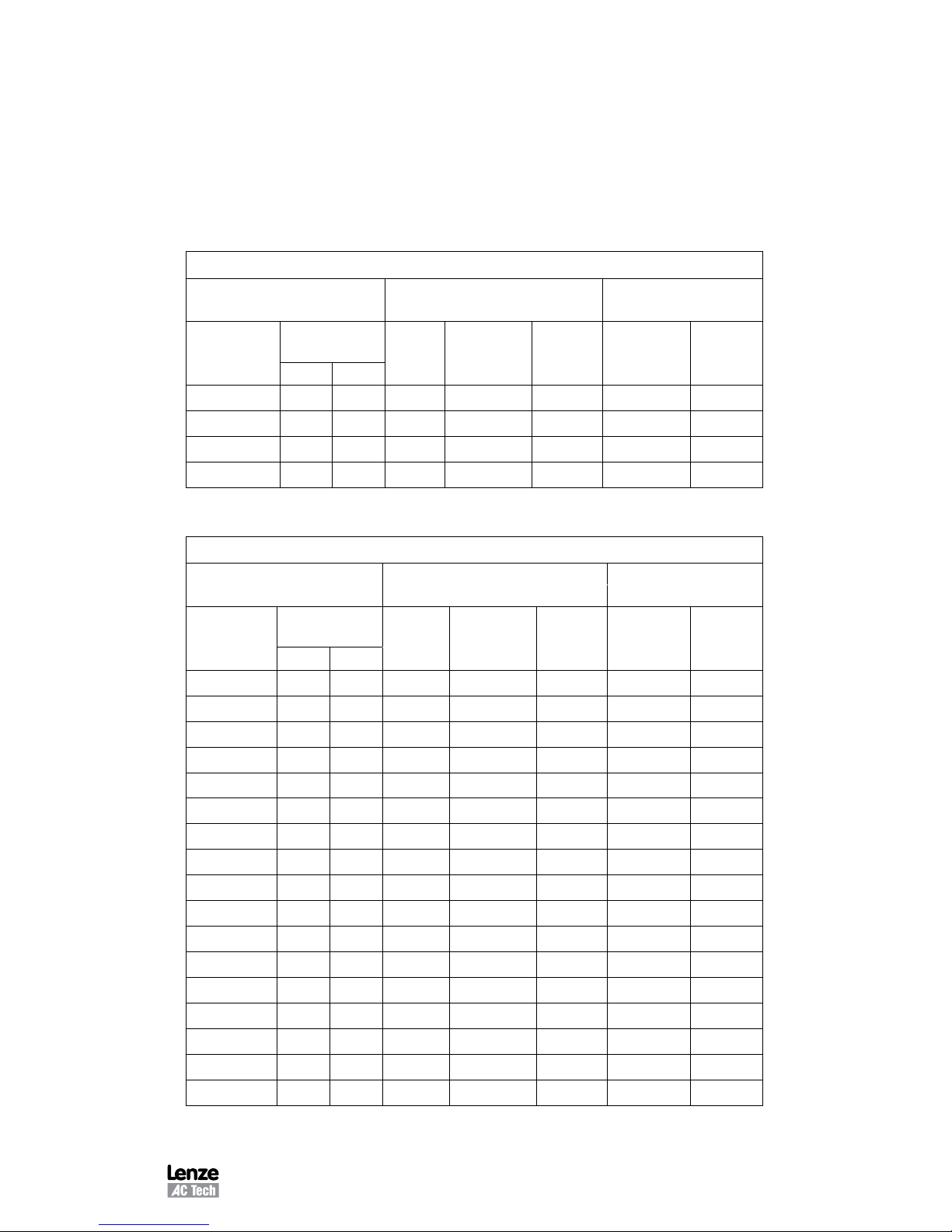
If the frequency applied to the motor is increased while the voltage remains constant,
torque capability will decrease as speed increases. This will cause the horsepower
capability of the motor to remain approximately constant. Motors run in this mode when
operated above base speed, where drive output voltage is limited by the input line
voltage. This operating range is known as the “constant horsepower” range. The typical
maximum range for constant horsepower is about 2.3 to 1 (60 to 140 Hz). The diagram
below depicts the characteristics of a typical AC induction motor with a 60 Hz base speed.
WARNING!
Consult motor manufacturer before operating motor and/or driven
equipment above base speed.
Phone: 800.894.0412 - Fax: 888.723.4773 - Web: www.clrwtr.com - Email: info@clrwtr.com
M301L 13
CONSTANT TORQUE
CONSTANT
HP
TORQUE HORSEPOWER
HORSEPOWER
TORQUE
FREQUENCY (Hz)
TORQUE (%)
20 40
60 80 100 120
150
130
110
90
70
50
30
10
6.1.1 VARIABLE TORQUE VS. CONSTANT TORQUE
Variable frequency drives, and the loads they are applied to, can generally be divided
into two groups: constant torque and variable torque. Constant torque loads include:
vibrating conveyors, punch presses, rock crushers, machine tools, and just about every
other application that is not considered variable torque. Variable torque loads include
centrifugal pumps and fans, which make up the majority of HVAC applications.
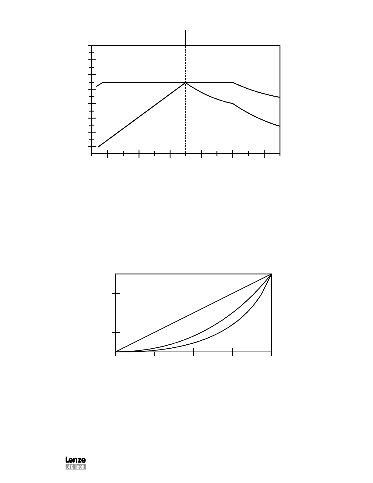
Variable torque loads are governed by the affinity laws, which define the relationships
between speed, flow, torque and horsepower. The diagram below illustrates these
relationships:
0%
25%
50%
75%
100%
100%
75%
50%
25%
0%
% SPEED
%
TORQUE
%
HORSEPOWER
%
FLOW
Phone: 800.894.0412 - Fax: 888.723.4773 - Web: www.clrwtr.com - Email: info@clrwtr.com

14 M301L
“Variable torque” refers to the fact that the torque required varies with the square of the
speed. Also, the horsepower required varies with the cube of the speed, resulting in a
large reduction in horsepower for even a small reduction in speed. It is easily seen that
substantial energy savings can be achieved by reducing the speed of a fan or pump.
For example, reducing the speed to 50% results in a 50 HP motor having to produce
only 12.5% of rated horsepower, or 6.25 HP. Variable torque drives usually have a low
overload capacity (110% - 120% for 60 seconds), because variable torque applications
rarely experience overload conditions. To optimize efficiency and energy savings, variable
torque drives are usually programmed to follow a variable V/Hz ratio.
The term “constant torque” is not entirely accurate in terms of the actual torque required
for an application. Many constant torque applications have reciprocating loads, such
as vibrating conveyors and punch presses, where the rotational motion of the motor is
being converted to a linear motion. In such cases, the torque required can vary greatly at
different points in the cycle. For constant torque loads, this fluctuation in torque is not a
direct function of speed, as it is with a variable torque load. As a result, constant torque
drives typically have a high overload rating (150% for 60 seconds) in order to handle
the higher peak torque demands. To achieve maximum torque, constant torque drives
follow a constant V/Hz ratio.
Both MC Series product lines (MC1000 and MC3000) have full overload capacity (150%
for 60 seconds, 180% for 30 seconds), so that either one can be used for either type of
application. The V/Hz ratio can also be changed to optimize performance for either type
of application.
6.2 DRIVE FUNCTION DESCRIPTION
The MC Series is a 16 bit microprocessor based, keypad programmable, variable speed
AC motor drive. There are four major sections: an input diode bridge and filter, a power
board, a control board, and an output intelligent power module.
6.2.1 DRIVE OPERATION
Incoming AC line voltage is converted to a pulsating DC voltage by the input diode
bridge. The DC voltage is supplied to the bus filter capacitors through a charge circuit
which limits inrush current to the capacitors during power-up. The pulsating DC voltage
is filtered by the bus capacitors which reduces the ripple level. The filtered DC voltage
enters the inverter section of the drive, composed of six output intelligent insulated gate
bi-polar transistors (IGBTs) which make up the three output legs of the drive. Each leg
has one intelligent IGBT connected to the positive bus voltage and one connected to the
negative bus voltage. Alternately switching on each leg, the intelligent IGBT produces
an alternating voltage on each of the corresponding motor windings. By switching each
output intelligent IGBT at a very high frequency (known as the carrier frequency) for
varying time intervals, the inverter is able to produce a smooth, three phase, sinusoidal
output current wave which optimizes motor performance.
Phone: 800.894.0412 - Fax: 888.723.4773 - Web: www.clrwtr.com - Email: info@clrwtr.com

M301L 15
6.2.2 CIRCUIT DESCRIPTION
The control section consists of a control board with a 16 bit microprocessor, keypad and
display. Drive programming is accomplished via the keypad or the serial communications
port. During operation the drive can be controlled via the keypad, by control devices wired
to the control terminal strip, or by the the serial communications port. The Power Board
contains the control and protection circuits which govern the six output IGBTs. The Power
Board also contains a charging circuit for the bus filter capacitors, a motor current feedback
circuit, a voltage feedback circuit, and a fault signal circuit. The drive has several built
in protection circuits. These include phase-to-phase and phase-to-ground short circuit
protection, high and low line voltage protection, protection against excessive ambient
temperature, and protection against continuous excessive output current. Activation of
any of these circuits will cause the drive to shut down in a fault condition.
6.2.3 MC3000 INPUTS AND OUTPUTS
The drive has two analog inputs (0-10 VDC and 4-20 mA) that can be used for speed
reference, PID setpoint reference, or PID feedback. A speed potentiometer (10,000 ohm)
can be used with the 0-10 VDC input.
There are also two analog outputs: one is proportional to speed (frequency), and the
other is proportional to load.
The drive has three programmable outputs for status indication: one Form C relay and
two open-collector outputs.
Refer to Sections 14 - CONTROL WIRING and 15 - CONTROL WIRING DIAGRAMS
for more information.
Phone: 800.894.0412 - Fax: 888.723.4773 - Web: www.clrwtr.com - Email: info@clrwtr.com

16 M301L
7 INSTALLATION
WARNING!
Drives must NOT be installed where subjected to adverse
environmental conditions! Drives must not be installed where
subjected to combustible, oily, or hazardous vapors or dust; excessive
moisture or dirt; strong vibration; excessive ambient temperatures.
Consult Lenze AC Tech for more information on the suitability of a
drive to a particular environment.
The drive should be mounted on a smooth vertical surface capable of safely supporting
the unit without vibrating. The LCD display has an optimum field of view, this should be
considered when determining the mounting position.
Chassis models must be installed in an electrical enclosure that will provide complete
mechanical protection and maintain uniform internal temperature within the drive’s ambient
operating temperature rating. All drive models MUST be mounted in a vertical position
for proper heatsink cooling.
Maintain a minimum spacing around the drive as follows:
SPACING REQUIREMENTS
HP
SPACING
INCHES mm
0.25 - 5 2 50
7.5 - 25 4 100
30 - 60 6 150
All drive models MUST be mounted in a vertical position for proper heatsink cooling.
Fans or blowers should be used to insure proper cooling in tight quarters. Do not mount
drives above other drives or heat producing equipment that would impede the cooling of
the drive. Note the ambient operating temperature ratings for each drive model.
If it is necessary to drill or cut the drive enclosure or panel, extreme care must be taken
to avoid damaging drive components or contaminating the drive with metal fragments
(which cause shorting of electrical circuits). Cover drive components with a clean cloth to
keep out metal chips and other debris. Use a vacuum cleaner to clean drive components
after drilling, even if chips do not appear to be present. Do not attempt to use positive
air pressure to blow chips out of drive, as this tends to lodge debris under electronic
components. Contaminating the drive with metal chips can cause drive failure and will
void the warranty.
The MC3000 Series is UL approved for solid state motor overload protection. Therefore, a
separate thermal overload relay is not required for single motor applications. In applications
where one drive is operating more than one motor, a separate thermal overload relay is
required for each motor per NEC.
Phone: 800.894.0412 - Fax: 888.723.4773 - Web: www.clrwtr.com - Email: info@clrwtr.com

M301L 17
7.1 INSTALLATION AFTER A LONG PERIOD OF STORAGE
WARNING!
Severe damage to the drive can result if it is operated after a long
period of storage or inactivity without reforming the DC bus capacitors!
If input power has not been applied to the drive for a period of time exceeding three
years (due to storage, etc), the electrolytic DC bus capacitors within the drive can change
internally, resulting in excessive leakage current. This can result in premature failure of
the capacitors if the drive is operated after such a long period of inactivity or storage.
In order to reform the capacitors and prepare the drive for operation after a long period
of inactivity, apply input power to the drive for 8 hours prior to actually operating the
drive/motor system.
7.2 EXPLOSION PROOF APPLICATIONS
Explosion proof motors that are not rated for inverter use lose their certification when
used for variable speed. Due to the many areas of liability that may be encountered when
dealing with these applications, the following statement of policy applies:
"Lenze AC Tech Corporation inverter products are sold with no warranty of fitness for a
particular purpose or warranty of suitability for use with explosion proof motors. Lenze
AC Tech Corporation accepts no responsibility for any direct, incidental or consequential
loss, cost, or damage that may arise through the use of its AC inverter products in these
applications. The purchaser expressly agrees to assume all risk of any loss, cost, or
damage that may arise from such application."
Phone: 800.894.0412 - Fax: 888.723.4773 - Web: www.clrwtr.com - Email: info@clrwtr.com

18 M301L
8 INPUT AC REQUIREMENTS
WARNING!
Hazard of electrical shock! Disconnect incoming power and wait
three minutes before servicing the drive. Capacitors retain charge
after power is removed.
8.1 INPUT AC POWER REQUIREMENTS
8.1.1 VOLTAGE
The input voltage must match the drive’s nameplate voltage rating. Voltage fluctuation
must not vary by greater than 10% overvoltage or 15% undervoltage.
NOTE
Drives with dual rated input voltage must be programmed for the
proper supply voltage - see Parameter 0 - LINE VOLTS in Section
18 - DESCRIPTION OF PARAMETERS.
The UL file for this drive shows that it is suitable for use on a circuit capable of delivering
not more than 200,000 RMS symmetrical amperes, at the drive’s rated voltage. The CSA
file identifies a short-circuit withstand rating of 5,000 RMS symmetrical amperes at the
drives rated voltage.
Three phase voltage imbalance must be less than 2.0% phase to phase. Excessive
phase to phase imbalance can cause severe damage to the drive’s power components.
Motor voltage should match line voltage in normal applications. The drive’s maximum
output voltage will equal the input voltage. Use extreme caution when using a motor with
a voltage rating which is different from the input line voltage.
8.1.2 SUPPLY TRANSFORMER kVA RATINGS
If the kVA rating of the AC supply transformer is greater than ten times the input kVA
rating of the drive, a drive isolation transformer, or a 2 - 3% input line reactor (also known
as a choke) must be added.
8.2 INPUT FUSING AND DISCONNECT REQUIREMENTS
A circuit breaker or a disconnect switch with fuses must be provided in accordance with
the National Electric Code (NEC) and all local codes.
The MC3000 drive is capable of withstanding up to 150% current overload for 60 seconds.
Select a fuse or magnetic trip circuit breaker rated at 1.5 times the input current rating
of the drive (the minimum size should be 10 amps, regardless of input current rating).
Refer to Section 5 – MC3000 RATINGS.
Minimum voltage rating of the protection device should be 250 Vac for 240/120 Vac and
240/200 Vac rated drives, and 600 Vac for 480/400 Vac and 590/480 Vac drives.
Current limiting type fuses should be used when input fusing is required. Select fuses
with low I
2
T values, rated at 200,000 AIC. Recommended fuses are Bussman type
kTk-R, JJN or JJS. Similar fuses with equivalent ratings by other manufacturers may
also be acceptable.
Phone: 800.894.0412 - Fax: 888.723.4773 - Web: www.clrwtr.com - Email: info@clrwtr.com
M301L 19
9 VOLTAGE SELECTION
9.1 INPUT VOLTAGE RATINGS
M3100 Series drives are rated for 240/120 Vac, 50-60 Hz input. The drive will function with
input voltage of 120 Vac (+10%, -15%) at 48 to 62 Hz when wired for 120 Vac input, or
with input voltage of 240 Vac (+10%, -15%), at 48 to 62 Hz, when wired for 240 Vac input.
M3200 Series drives are rated for 240/200 Vac, 50-60 Hz input. The drive will function
with input voltages of 200 to 240 Vac (+10%, -15%), at 48 to 62 Hz.
M3400 Series drives are rated for 480/400 Vac, 50-60 Hz input. The drive will function
with input voltages of 400 to 480 Vac (+10%, -15%), at 48 to 62 Hz.
M3500 Series drives are rated for 590/480 Vac, 50-60 Hz input. The drive will function
with input voltages of 480 to 590 Vac (+10%, -15%), at 48 to 62 Hz.
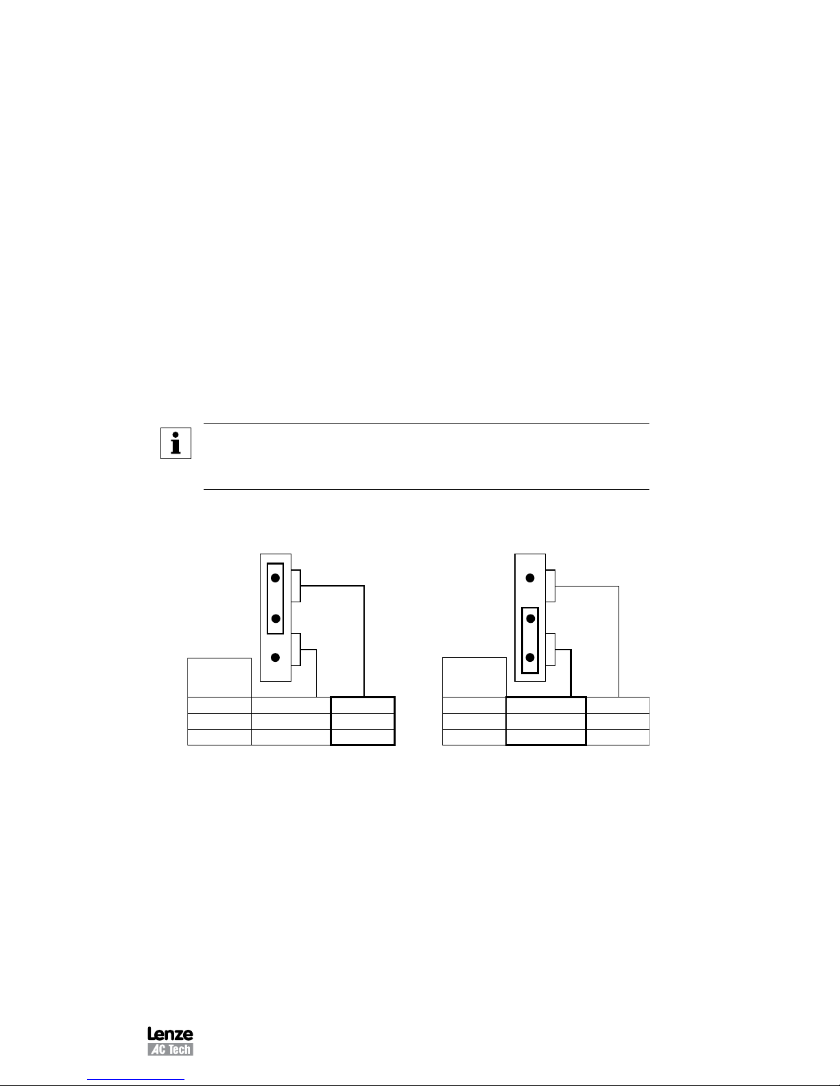
To select the proper input voltage on 240/200 VAC 30-60 Hp models, 400/480 VAC 75-
150 Hp and 480/590 VAC 75-150 Hp models the PL2 plug must be in the correct position.
PL2 is located either at the lower right corner, or upper right corner of the power board,
depending on horsepower. The PL2 plug is used to select the correct input voltage. Plug
PL2 into the top and middle pins to select 240, 480, or 590 VAC or the middle and bottom
pins to select 200, 400, or 480.
NOTE:
In addition to the voltage plug selection, Parameter 0 – LINE VOLTS must also
be programmed for the proper voltage. Refer to Section 18 - DESCRIPTION OF
PARAMETERS.
Voltage Selection Plug (PL2)
MODEL
CODE
1200
1400
1500
200V
400V
480V
240V
480V
590V
240 / 480 / 590 Vac INPUT
MODEL
CODE
1200
1400
1500
200V
400V
480V
240V
480V
590V
200 / 400 / 480 Vac INPUT
PL2 PL2
Phone: 800.894.0412 - Fax: 888.723.4773 - Web: www.clrwtr.com - Email: info@clrwtr.com

20 M301L
10 POWER WIRING
WARNING!
Hazard of electrical shock! Disconnect incoming power and wait
three minutes before servicing the drive. Capacitors retain charge
after power is removed.
Note the drive input and output current ratings and check applicable electrical codes for
required wire type and size, grounding requirements, overcurrent protection, and incoming
power disconnect, before wiring the drive. Size conservatively to minimize voltage drop.
Input fusing and a power disconnect switch or contactor MUST be wired in series with
terminals L1, L2, and L3 (L1 and L2 if input is single phase). If one has not been supplied
by Lenze AC Tech Corporation, a disconnect means must be wired during installation.
This disconnect must be used to power down the drive when servicing, or when the
drive is not to be operated for a long period of time, but should not be used to start and
stop the motor.
Repetitive cycling of a disconnect or input contactor (more than once every two
minutes) may cause damage to the drive.
10.1 WIRING FOR SINGLE PHASE OR THREE PHASE INPUT
If the drive is nameplated for 240/120 Vac single phase input, wire the input to terminals
L1 and N and jumper terminals L1 to L2 for 120 Vac input voltage, or wire to terminals
L1 and L2 (do not wire to N) for 240 Vac input voltage. Refer to Section 11 - MC3000
POWER WIRING DIAGRAM.
If the drive is nameplated for three phase input only, wire the input to terminals L1, L2,
and L3.
All three power output wires, from terminals T1, T2, and T3 to the motor, must be kept
tightly bundled and run in a separate conduit away from all other power and control wiring.
It is not recommended to install contactors or disconnect switches between the drive and
motor. Operating such devices while the drive is running can potentially cause damage
to the drive's power components. If such a device is required, it should only be operated
when the drive is in a STOP state. If there is potential for the device to be opened while
the drive is running, the drive must be programmed for COAST TO STOP (see Parameter
26 - STOP), and an auxiliary contact on the device must be interlocked with the drive's
run circuit. This will give the drive a stop command at the same time the device opens,
and will not allow the drive to start again until the device is closed.
Phone: 800.894.0412 - Fax: 888.723.4773 - Web: www.clrwtr.com - Email: info@clrwtr.com
 Loading...