

Page 1
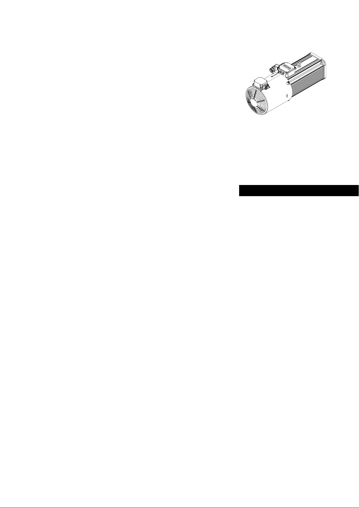
M... MCA19, MCA21
Asynchronous servo motors with spring−applied
brake mounted on the B−bearing side
Supplement to Operating Instructions
EN
.Z!z
Ä.Z!zä
Page 2

Please read these instructions before you start working!
Follow the safety instructions enclosed.
Important notes
This supplement is only valid together with the general motor operating instructions, see Internet!
Invalid chapters of the motor operating instructions: none
Additions to the "Maintenance and repair" section:
Stop!
When replacing the brake, complete rotor or the hub, the spare part from the
corresponding Lenze repair kit must always be used.
Characteristics and maintenance of the BFK457−16 R and BFK458−18 spring−applied brakes.
Encoder dismounting and mounting.
0Abb. 0Tab. 0
Page 3

Contents i
1 Mechanical installation 4. . . . . . . . . . . . . . . . . . . . . . . . . . . . . . . . . . . . . . . . . . . . . . . . . . . . . . . . .
1.1 Important notes 4. . . . . . . . . . . . . . . . . . . . . . . . . . . . . . . . . . . . . . . . . . . . . . . . . . . . . . .
1.2 Spring−applied brake − holding brake 5. . . . . . . . . . . . . . . . . . . . . . . . . . . . . . . . . . . . .
1.2.1 Characteristics 5. . . . . . . . . . . . . . . . . . . . . . . . . . . . . . . . . . . . . . . . . . . . . . . .
1.2.2 BFK457−16R design − non−adjustable 5. . . . . . . . . . . . . . . . . . . . . . . . . . . . .
1.2.3 BFK458−18 design − adjustable 5. . . . . . . . . . . . . . . . . . . . . . . . . . . . . . . . . .
2 Maintenance/repair 6. . . . . . . . . . . . . . . . . . . . . . . . . . . . . . . . . . . . . . . . . . . . . . . . . . . . . . . . . . . .
2.1 Spring−applied brake − holding brake 6. . . . . . . . . . . . . . . . . . . . . . . . . . . . . . . . . . . . .
2.1.1 Wear on spring−applied brakes 7. . . . . . . . . . . . . . . . . . . . . . . . . . . . . . . . . .
2.1.2 Maintenance 8. . . . . . . . . . . . . . . . . . . . . . . . . . . . . . . . . . . . . . . . . . . . . . . . .
2.1.3 Dismounting the MCA19 and 21 fan cover 9. . . . . . . . . . . . . . . . . . . . . . . .
2.1.4 BFK457−16R air gap 10. . . . . . . . . . . . . . . . . . . . . . . . . . . . . . . . . . . . . . . . . . .
2.1.5 Checking and re−adjusting the BFK458−18 air gap 11. . . . . . . . . . . . . . . . . .
2.2 Replacing the brake 12. . . . . . . . . . . . . . . . . . . . . . . . . . . . . . . . . . . . . . . . . . . . . . . . . . . .
2.2.1 Dismounting the MCA 19 and 21 encoder 12. . . . . . . . . . . . . . . . . . . . . . . . .
2.3 BFK457−16R 13. . . . . . . . . . . . . . . . . . . . . . . . . . . . . . . . . . . . . . . . . . . . . . . . . . . . . . . . . .
2.3.1 Dismounting and mounting 13. . . . . . . . . . . . . . . . . . . . . . . . . . . . . . . . . . . .
2.4 BFK458−18 16. . . . . . . . . . . . . . . . . . . . . . . . . . . . . . . . . . . . . . . . . . . . . . . . . . . . . . . . . . .
2.4.1 Dismounting and mounting 16. . . . . . . . . . . . . . . . . . . . . . . . . . . . . . . . . . . .
2.4.2 Encoder mounting 19. . . . . . . . . . . . . . . . . . . . . . . . . . . . . . . . . . . . . . . . . . . .
Lenze ¯ MA 33.0012 ¯ 1.0
3
Page 4

1
1 Mechanical installation
1.1 Important notes
The brake that is mounted here is specially adapted to the use on the MCA 19 and 21.
Mechanical installation
Important notes
Stop!
If the wear air gap of a spring−applied brake is reached, the brake will no
longer be released. In this case, the complete rotor of the brake must be
replaced.
Note!
¯ BFK457−16R: It is not possible to re−adjust the brake. The complete
rotor must be replaced.
¯ BFK458−18: When the wear limit has been reached, the brake must be
re−adjusted, or the complete rotor must be replaced.
Safety system
Stop!
If a safety encoder is used, all maintenance and installation work must be
performed at the Lenze site.
Otherwise any warranty will expire and Lenze GmbH will not accept any
liability for consequential damage.
The IG2048−5V−V3
not be dismounted and mounted. This service work is performed by Lenze.
safety encoder can be mounted on the brakes described here and must
4
Lenze ¯ MA 33.0012 ¯ 1.0
Page 5
1.2 Spring−applied brake − holding brake
1.2.1 Characteristics
Mechanical installation
Spring−applied brake − holding brake
Characteristics
1
Motor type Type of brake
MCA19 BFK457−16R 0.3 0.6 −−− −−− −−− 24.6 4
MCA21 BFK458−18 0.4 0.6 3.0 10.0 13.0 24.6 6
s
Lrated
+0.1 / −0.05
[mm] [mm] [mm] min. [mm] max. [mm] [Nm] No. of pieces
s
Lmax.
holding brake
Max.
adjustment,
permissible
wear path
Rotor thickness Tightening
torque of the
fixing screws
Fixing screws
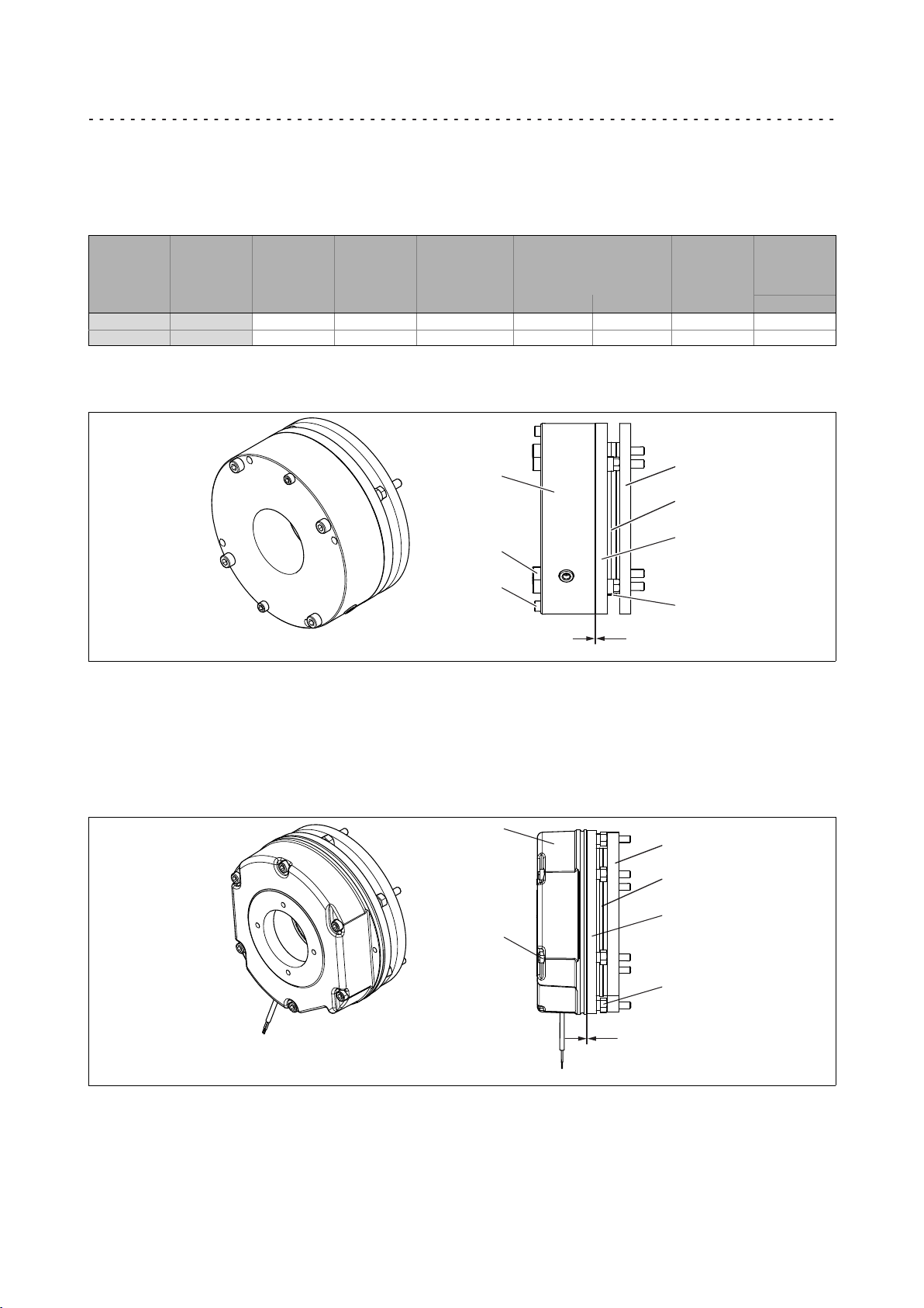
1.2.2 BFK457−16R design − non−adjustable
1
5
3
2
6
7
4
s
L
Fig. 1 Design of an INTORQ BFK457−16 Compact spring−applied brake, fully mounted rotor and flange
1 Stator 3 Rotor with friction lining 6 Fixing screws
2 Armature plate 4 Spacer bush 7 Screws of the emergency manual
5 Flange s
release
Air gap
L
1.2.3 BFK458−18 design − adjustable
1
5
3
2
6
8
s
L
Fig. 2 Design of an INTORQ BFK458 spring−applied brake: basic module E (complete stator) + rotor + hub + flange
1 Stator 3 Rotor with friction lining 6 Fixing screws
2 Armature plate 5 Flange 8 Sleeve bolts
s
Air gap
L
Lenze ¯ MA 33.0012 ¯ 1.0
5
Page 6

2
Maintenance/repair
Spring−applied brake − holding brake
2 Maintenance/repair
2.1 Spring−applied brake − holding brake
The brakes need to be checked on a regular basis to ensure safe and trouble−free
operation.
The necessary maintenance intervals primarily depend on the stress to which the brake
is subjected in an application. When a maintenance interval is being calculated, all
causes of wear must be taken into account (see notes "Wear on spring−applied brakes").
In the case of brakes which are subjected to low levels of stress, e.g. holding brakes with
emergency stop function, regular inspections at a fixed time interval are recommended.
In order to reduce the amount of work involved in maintenance, perform the inspection
at the same time as other maintenance work carried out cyclically on the machine if
possible.
If the brakes are not properly serviced, operating faults, production outages or damage
to machinery can occur. A maintenance concept adapted to the operating conditions
and the stresses to which the brakes are subjected must therefore be drawn up for every
application. For brakes, the maintenance intervals and servicing work listed in the
following table are necessary.
Maintenance interval for holding brake with
emergency stop
At least every 2 years
After 1 million cycles at the latest
Shorter intervals in the case of frequent emergency
stops!
Maintenance work
Inspection of the brake integrated in the motor:
¯ Check ventilation function and
activation/deactivation
¯ Measure air gap (re−adjust air gap, if necessary),
2.1.4
6
Lenze ¯ MA 33.0012 ¯ 1.0
Page 7

2.1.1 Wear on spring−applied brakes
Causes of wear
Component Effect Influencing factors Cause
Friction lining Wear on the friction lining Applied friction energy
Number of start−stop
cycles
Armature plate and
flange
Teeth of the brake
rotor
Armature plate
bracket
Springs Fatigue failure of the
Running−in of armature
plate and flange
Teeth wear (primarily at
the rotor end)
Armature plate, cap screws
and bolts are deflected
springs
Applied friction energy Friction between the brake
Number of start−stop
cycles,
Level of the braking
torque,
Dynamics of the
application,
Speed fins in operation
Number of start−stop
cycles,
Level of braking torque
Number of switching
operations of the brake
Braking during operation
(impermissible, holding
brakes!)
Emergency stops
Overlapping wear when
the drive starts and stops
Active braking by the drive
motor with the help of the
brake (quick stop)
Starting wear if motor is
mounted in a position
with the shaft vertical,
even if the brake is open
lining and the armature
plate or flange e.g. during
emergency braking or
service brake operation
Relative movement and
impacts between brake
rotor and brake hub
Load changes and impacts
due to reversal error
during interaction
between armature plate,
cap screws and guide bolts
Axial load cycle and
shearing stress on the
springs due to radial
reversing error of the
armature plate
Maintenance/repair
Spring−applied brake − holding brake
Wear on spring−applied brakes
2
Inspection of the individual parts
With a mounted brake ¯ Check release function and control
¯ Measure air gap (re−adjust, if necessary)
¯ Measure rotor thickness (replace rotor, if necessary)
¯ Thermal damage of armature plate or flange (tarnished
dark blue)
With a dismounted brake ¯ Check clearance of the rotor gear teeth (replace rotors that are damaged
by vibration)
¯ Damage by vibration of the torque support at the sleeve bolts, cylindrical
pins, and armature plate
¯ Check springs for damage
¯ Check armature plate and flange or end shield
– Max. run−in depth = rated air gap of the design size
Lenze ¯ MA 33.0012 ¯ 1.0
7
Page 8

2
2.1.2 Maintenance
Maintenance/repair
Spring−applied brake − holding brake
Maintenance
Stop!
The brakes must not be actuated without blowers.
Danger!
¯ Only work on the drive system when it is in a deenergised state!
¯ Hot motor surfaces of up to 140 °C. Observe cooling times!
¯ Remove loads acting on motors or secure loads acting on the drive!
Note!
Always fully replace brakes with defective armature plates, cylinder head
screws, springs or counter friction faces.
¯ The brakes used are not fail−safe because interference factors which
cannot be influenced (e.g. oil ingress) may lead to a reduction in
torque.
¯ When the rotor has been replaced, the original braking torque is only
attained after the friction surfaces have run in. After the rotor
replacement, increased initial wear will occur if the armature plate and
counter friction faces are not run in.
Tools required
Type Torque key
BFK457−16
BFK458−18 20 to 100 6 x 1/2"
Use for hexagon socket
Measuring
range [Nm]
20 to 100 6 x 1/2"
screws
Width across
flats [mm]
square
square
Open−jawed spanner width
across flats [mm]
Sleeve bolts Two−flat
lever
*
−−−−− −−−−− −−−−−
15 10 13 x 1/2"
Box spanner
mounting on
the outside
Width across
flats [mm]
square
for flange
Feeler gauge
8
Lenze ¯ MA 33.0012 ¯ 1.0
Page 9

Maintenance/repair
1
2
Spring−applied brake − holding brake
Dismounting the MCA19 and 21 fan cover
2.1.3 Dismounting the MCA19 and 21 fan cover
The brake is mounted to the N−end shield of the motor. Remove the fan cover to
check, maintain, or set the brake.
1. Disconnect the mains plug (1) of the fan.
2. Loosen the four screws (2) with which the fan is fitted onto the non−drive end
shield and remove the fan.
2
Lenze ¯ MA 33.0012 ¯ 1.0
9
Page 10

2
2.1.4 BFK457−16R air gap
Maintenance/repair
BFK457−16R air gap
Dismounting the MCA19 and 21 fan cover
Stop!
¯ The motor must not run whilst the air gap is checked.
¯ Do not insert feeler gauge further than 10 mm between the armature
plate (2) and stator (1)!
1
2
6
1 Complete stator 6 Fixing screw
2 Armature plate
1. Check air gap near the fixing screws (6) between the armature plate (2) and the
stator (1) using a feeler gauge and compare the values to the data "s
table, 5.
If the value measured, "s
replaced ( 12).
1
Air gap
À
Lrated
", is outside the tolerance ( 5), the rotor must be
Lrated
" in the
10
Lenze ¯ MA 33.0012 ¯ 1.0
Page 11

Checking and re−adjusting the BFK458−18 air gap
-
+
2.1.5 Checking and re−adjusting the BFK458−18 air gap
Stop!
¯ The motor must not run whilst the air gap is checked.
¯ Do not insert feeler gauge further than 10 mm between the armature
plate (2) and stator (1)!
1
Maintenance/repair
Dismounting the MCA19 and 21 fan cover
2
9
2
1
6
1 Complete stator 6 Fixing screw
2 Armature plate 9 Sleeve bolt
1. Check air gap near the fixing screws (6) between the armature plate (2) and the
stator (1) using a feeler gauge and compare the values to the data "s
table, 5.
If the value measured, "s
must be re−adjusted!
2. Slightly loosen the six fixing screws (6).
3. Slightly adjust the sleeve bolts (9) by rotation using the open−jawed spanner.
", is outside the tolerance of "s
Lrated
Lrated
Lrated
" ( 5), the air gap
Air gap
À
" in the
– If the air gap is too large, into the complete stator (1).
– If the air gap is too small, out of the complete stator (1).
– 1/6 revolution changes the air gap by approx. 0.15 mm
4. Tighten the fixing screws (6) with 24.6 Nm.
5. Repeat the air gap check and re−adjust the air gap again, if necessary, or replace
the brake.
Lenze ¯ MA 33.0012 ¯ 1.0
11
Page 12

2
2.2 Replacing the brake
2.2.1 Dismounting the MCA 19 and 21 encoder
Maintenance/repair
Replacing the brake
Dismounting the MCA 19 and 21 encoder
Stop!
If a safety encoder is used, all maintenance and installation work must be
performed at the Lenze site.
Otherwise any warranty will expire and Lenze GmbH will not accept any
liability for consequential damage.
Tools required
¯ Allen key width across flats 1.5
¯ Open−jawed spanner width across flats 7
¯ Open−jawed spanner width across flats 13
Danger!
Risk of injury!
There may be sharp edges on the metal sheet of the torque plate.
10.6/10.7
1 Complete stator 10.1 M8 nut 10.4 Stud bolts
6 Fixing screws 10.2 M4 nut 10.6 Protective plate
10 Encoder 10.3 Threaded bolt 10.7 Torque plate
1. Loosen brake cable in the terminal box.
10.2
1
10.1
6
10.3
10
10.4
2. Loosen two stud bolts (10.4) on the motor shaft. In the case of an incremental
encoder, loosen the clamping hub.
3. Unscrew the upper M4 nut (10.2) of the torque plate (10.6) of the encoder.
4. Carefully slide the encoder (10) off the motor shaft and make sure that you do not
loose the protective plate (10.7) of the torque plate.
5. Loosen the M8 nut (10.1) of the threaded bolt (10.3). The threaded bolt remains in
the end shield.
6. Now the brake can be dismounted.
12
Lenze ¯ MA 33.0012 ¯ 1.0
Page 13

2.3 BFK457−16R
2.3.1 Dismounting and mounting
Stop!
When replacing the brake, the complete rotor or the hub, the spare part
from the corresponding Lenze repair kit must always be used. It can be
ordered from the Lenze Service, specifying the motor serial number and
the motor material number.
11
8
5
12
3
2
1
6
Maintenance/repair
BFK457−16R
Dismounting and mounting
2
1 Complete stator 6 Fixing screws 11 Motor end shield
5 Flange 8 Hub
1. Loosen brake cable.
2. Evenly loosen and fully unscrew the four fixing screws (6).
3. Remove stator (1) with complete rotor from end shield (11). Observe brake cable!
4. Check toothing of the hub (2). If it shows signs of wear, it has to be replaced.
Lenze ¯ MA 33.0012 ¯ 1.0
13
Page 14

2
Dismounting and mounting the hub
7.2
Maintenance/repair
BFK457−16R
Dismounting and mounting
11
9
12
7.1
8
7.1
Circlip/retaining ring
7.2 9 Keyway 12 Motor shaft
1. Remove circlip (7.2)
In order to provide for more stability (alternating load), the hub is additionally glued to
the shaft.
2. The hub (8) must be heated to 150 − 160 °C and then removed from the shaft by
means of an extractor. (If necessary, have this work carried out by the Lenze
Service staff).
3. Remove circlip (7.1)
4. The seat of the hub must be cleaned, ensuring that an adhesive bond between the
shaft and hub can be re−established afterwards.
5. Fit a circlip (7.1) in order to provide for horizontal fixation and fit the featherkey
(9) onto the shaft.
6. Heat the hub (8) to 120°C and slide it onto the shaft while it is warm.
8 Hub 11 Motor end shield
– With an alternating load, we recommend securing the hub on the shaft using a
high−strength adhesive (Loctite 603 or Weicon 306−03).
7. Fit the circlip (7.2) onto the hub.
14
Lenze ¯ MA 33.0012 ¯ 1.0
Page 15

Stop!
Check the condition of the brake flange (5) and armature plate (2)!
¯ In the case of heavy scoring, the parts must be replaced.
¯ Both parts must be free from grease and oil!
3
2
1
13
6
Maintenance/repair
BFK457−16R
Dismounting and mounting
11
8
5
12
2
1 Complete stator 5 Flange 11 Motor end shield
2 Armature plate 6 Fixing screws 12 Shaft
3 Complete rotor 8 Hub 13 M6 cylinder head screw
1. Slide the new rotor (3) with the toothed intermediate ring onto the hub and check
whether it can be shifted manually.
2. Align and position the drill holes of the brake flange (5) towards the threaded
holes in the non−drive end shield (11).
3. Fit the complete stator with rotor (1) and tighten it with 24.6 Nm using the four
fixing screws (6).
4. Remove two M6 cylinder head screws (13) for the emergency manual
release/transport locking device, thus enabling the armature plate (2) to move
freely.
5. Measure the air gap between the stator (1) and armature plate (2)
(0.3 +0.1/−0.05 mm).
6. Reconnect the brake cable.
7. Perform a functional check of the brake. When the power is switched on, the air
gap between the magnet housing and the armature plate must be SL = 0, i.e. the
rotor must be enabled to move freely.
Stop!
Ensure that the screws of the emergency manual release/transport
locking device have been removed!
Lenze ¯ MA 33.0012 ¯ 1.0
15
Page 16

2
2.4 BFK458−18
2.4.1 Dismounting and mounting
Maintenance/repair
BFK458−18
Dismounting and mounting
Stop!
When replacing the brake, complete rotor or the hub, the spare part from
the corresponding Lenze repair kit must always be used. It can be ordered
from the Lenze Service, specifying the motor serial number and the motor
material number.
11
5
10.3
8
3
2
10.1
1
6
1 Complete stator 5 Flange 10.1 M8 nut
2 Armature plate 6 Fixing screws 10.3 Threaded bolt
3 Complete rotor 8 Hub 11 Motor end shield
1. Loosen brake cable.
2. Loosen the five fixing screws (6) and the nut (10.1) evenly and fully uncrew them.
The threaded bolt (10.3) remains in the motor end shield as a guide.
3. Remove complete stator (1) from the motor end shield (11). Observe brake cable!
4. Remove complete rotor (3) from the hub (8).
5. Check toothing of the hub (8). If it shows signs of wear, it has to be replaced.
16
Lenze ¯ MA 33.0012 ¯ 1.0
Page 17

Dismounting and mounting the hub
11
9
12
7.1
8
7.2
Maintenance/repair
BFK458−18
Dismounting and mounting
2
7.1
Circlip/retaining ring
7.2 9 Keyway 12 Motor shaft
1. Remove circlip (7.2)
In order to provide for more stability (alternating load), the hub is additionally glued to
the shaft.
2. The hub (8) must be heated to 150 − 160 °C and then removed from the shaft by
means of an extractor. (If necessary, have this work carried out by the Lenze
Service staff).
3. Remove circlip (7.1)
4. The seat of the hub must be cleaned, ensuring that an adhesive bond between the
shaft and hub can be re−established afterwards.
5. Fit a circlip (7.1) in order to provide for horizontal fixation and fit the featherkey
(9) onto the shaft.
6. Heat the hub (8) to 120°C and slide it onto the shaft while it is warm.
8 Hub 11 Motor end shield
– With an alternating load, we recommend securing the hub on the shaft using a
high−strength adhesive (Loctite 603 or Weicon 306−03).
7. Fit the circlip (7.2) onto the hub.
Lenze ¯ MA 33.0012 ¯ 1.0
17
Page 18

2
Maintenance/repair
BFK458−18
Dismounting and mounting
Stop!
Check the condition of the brake flange (5) and armature plate (2)!
¯ In the case of heavy scoring, the parts must be replaced.
¯ Both parts must be free from grease and oil!
2
1
6
11
5
8
3
1 Complete stator 5 Flange 11 Motor end shield
2 Armature plate 6 Fixing screws
3 Complete rotor 8 Hub
1. Slide the new rotor (3) with the toothed intermediate ring onto the hub and check
whether it can be shifted manually.
2. Align and position the drill holes of the brake flange (5) towards the threaded
holes in the non−drive end shield (11).
3. Fit the stator (1) and tighten it with 24.6 Nm using the six fixing screws (6).
4. Measure the air gap between the stator and armature plate (2)
(0.4 +0.1/−0.05 mm).
5. Reconnect the brake cable.
6. Perform a functional check of the brake. When the voltage is switched on, the air
gap between the magnet housing and the armature plate must be SL = 0, i.e. the
rotor must be enabled to move freely.
18
Lenze ¯ MA 33.0012 ¯ 1.0
Page 19

2.4.2 Encoder mounting
Maintenance/repair
BFK458−18
Encoder mounting
2
10.6/10.7
1 Complete stator 10.1 M8 nut 10.4 Stud bolts 12 Motor shaft
6 Fixing screws 10.2 M4 nut 10.6 Protective plate
10 Encoder 10.3 Threaded bolt 10.7 Torque plate
10.2
10.1
10.3
10.4
1
6
12
10
Stop!
After having dismounted and mounted the encoder, it is absolutely
necessary to perform a reference run. If this step is ignored, collision
damage may be the consequence.
6
1. After the brake has been mounted successfully, screw the threaded bolt (10.3)
into the non−drive end shield first and then counter it using the M8 nut (10.1),
tightening torque = 24.6 Nm.
2. Carefully slide the encoder (10) onto the shaft (12), fitting the torque plate (10.7)
with the protective plate (10.6) onto the threaded bolt (10.3). Then tighten the
two stud bolts on the motor shaft (10.4) with 1.5 Nm and secure them by means
of medium−strength screw glue or locking varnish.
3. Mount the upper M4 nut (10.2) in order to axially secure the torque plate and
tighten it with 3 Nm, clamping the torque plate against the lower M4 nut (10.2).
Stop!
The torque plate must be tension−free and has to be positioned at right
angles to the motor−encoder shaft. Otherwise the service life of the
encoder bearings may be reduced!
Lenze ¯ MA 33.0012 ¯ 1.0
19
Page 20

© 01/2019 | MA 33.0012 | .Z!z | 1.0 | TD09
Lenze Drives GmbH
Postfach 10 13 52, 31763 Hameln
Breslauer Straße 3, 32699 Extertal
GERMANY
HR Lemgo B 6478
+49515482−0
+49515482−2800
sales.de@lenze.com
www.lenze.com
Lenze Service GmbH
Breslauer Straße 3, D−32699 Extertal
Germany
0080002446877 (24 h helpline)
+49515482−1112
service.de@lenze.com
10987654321
 Loading...