

Page 1
EDS82ZAFPC010
.IFJ
Ä.IFJä
L−force Communication
Communication Manual
PROFIBUS−DP
E82ZAFPC001 / E82ZAFPC010
Function module
Page 2

Contentsi
1 About this documentation 3 . . . . . . . . . . . . . . . . . . . . . . . . . . . . . . . . . . . . . . . . . . . . . . . . . .
1.1 Document history 4 . . . . . . . . . . . . . . . . . . . . . . . . . . . . . . . . . . . . . . . . . . . . . . . . . . . .
1.2 Conventions used 5 . . . . . . . . . . . . . . . . . . . . . . . . . . . . . . . . . . . . . . . . . . . . . . . . . . . .
1.3 Terminology used 5 . . . . . . . . . . . . . . . . . . . . . . . . . . . . . . . . . . . . . . . . . . . . . . . . . . . .
1.4 Notes used 6 . . . . . . . . . . . . . . . . . . . . . . . . . . . . . . . . . . . . . . . . . . . . . . . . . . . . . . . . . .
2 Safety instructions 7 . . . . . . . . . . . . . . . . . . . . . . . . . . . . . . . . . . . . . . . . . . . . . . . . . . . . . . . . .
2.1 General safety information 7 . . . . . . . . . . . . . . . . . . . . . . . . . . . . . . . . . . . . . . . . . . . .
2.2 Device− and application−specific safety instructions 8 . . . . . . . . . . . . . . . . . . . . . . . .
2.3 Residual hazards 8 . . . . . . . . . . . . . . . . . . . . . . . . . . . . . . . . . . . . . . . . . . . . . . . . . . . . .
3 Product description 9 . . . . . . . . . . . . . . . . . . . . . . . . . . . . . . . . . . . . . . . . . . . . . . . . . . . . . . . .
3.1 Application as directed 9 . . . . . . . . . . . . . . . . . . . . . . . . . . . . . . . . . . . . . . . . . . . . . . .
3.2 Identification 10 . . . . . . . . . . . . . . . . . . . . . . . . . . . . . . . . . . . . . . . . . . . . . . . . . . . . . . . .
3.3 Product features 11 . . . . . . . . . . . . . . . . . . . . . . . . . . . . . . . . . . . . . . . . . . . . . . . . . . . . .
3.4 Connections and interfaces 12 . . . . . . . . . . . . . . . . . . . . . . . . . . . . . . . . . . . . . . . . . . . .
4 Technical data 13 . . . . . . . . . . . . . . . . . . . . . . . . . . . . . . . . . . . . . . . . . . . . . . . . . . . . . . . . . . . .
4.1 General data 13 . . . . . . . . . . . . . . . . . . . . . . . . . . . . . . . . . . . . . . . . . . . . . . . . . . . . . . . .
4.2 Operating conditions 13 . . . . . . . . . . . . . . . . . . . . . . . . . . . . . . . . . . . . . . . . . . . . . . . . .
4.3 Protective insulation 14 . . . . . . . . . . . . . . . . . . . . . . . . . . . . . . . . . . . . . . . . . . . . . . . . . .
4.4 Connection terminals 15 . . . . . . . . . . . . . . . . . . . . . . . . . . . . . . . . . . . . . . . . . . . . . . . . .
4.5 Communication time 16 . . . . . . . . . . . . . . . . . . . . . . . . . . . . . . . . . . . . . . . . . . . . . . . . .
4.6 Dimensions 17 . . . . . . . . . . . . . . . . . . . . . . . . . . . . . . . . . . . . . . . . . . . . . . . . . . . . . . . . . .
5 Installation 18 . . . . . . . . . . . . . . . . . . . . . . . . . . . . . . . . . . . . . . . . . . . . . . . . . . . . . . . . . . . . . . .
5.1 Mechanical installation 18 . . . . . . . . . . . . . . . . . . . . . . . . . . . . . . . . . . . . . . . . . . . . . . . .
5.2 Electrical installation 19 . . . . . . . . . . . . . . . . . . . . . . . . . . . . . . . . . . . . . . . . . . . . . . . . . .
5.2.1 Wiring according to EMC (CE−typical drive system) 19 . . . . . . . . . . . . . . . . .
5.2.2 Wiring with a host (master) 20 . . . . . . . . . . . . . . . . . . . . . . . . . . . . . . . . . . . .
5.2.3 Voltage supply 23 . . . . . . . . . . . . . . . . . . . . . . . . . . . . . . . . . . . . . . . . . . . . . .
5.2.4 Terminal assignment 26 . . . . . . . . . . . . . . . . . . . . . . . . . . . . . . . . . . . . . . . . .
5.2.5 Cable cross−sections and screw−tightening torques 28 . . . . . . . . . . . . . . . . .
5.2.6 Use of plug connectors 29 . . . . . . . . . . . . . . . . . . . . . . . . . . . . . . . . . . . . . . . .
5.3 Bus cable length 30 . . . . . . . . . . . . . . . . . . . . . . . . . . . . . . . . . . . . . . . . . . . . . . . . . . . . . .
2
EDS82ZAFPC010 EN 4.0
Page 3

Contents i
6 Commissioning 31 . . . . . . . . . . . . . . . . . . . . . . . . . . . . . . . . . . . . . . . . . . . . . . . . . . . . . . . . . . .
6.1 Before switching on 31 . . . . . . . . . . . . . . . . . . . . . . . . . . . . . . . . . . . . . . . . . . . . . . . . . .
6.2 Commissioning steps 32 . . . . . . . . . . . . . . . . . . . . . . . . . . . . . . . . . . . . . . . . . . . . . . . . .
6.3 Configuring the host system (master) 34 . . . . . . . . . . . . . . . . . . . . . . . . . . . . . . . . . . .
6.3.1 Adapting device controls 36 . . . . . . . . . . . . . . . . . . . . . . . . . . . . . . . . . . . . . . .
6.3.2 Defining the user data length 37 . . . . . . . . . . . . . . . . . . . . . . . . . . . . . . . . . . .
6.4 Activating the bus terminating resistor 38 . . . . . . . . . . . . . . . . . . . . . . . . . . . . . . . . . .
6.5 Setting the node address 39 . . . . . . . . . . . . . . . . . . . . . . . . . . . . . . . . . . . . . . . . . . . . .
6.6 Connecting the mains voltage 40 . . . . . . . . . . . . . . . . . . . . . . . . . . . . . . . . . . . . . . . . . .
7 Process data transfer 41 . . . . . . . . . . . . . . . . . . . . . . . . . . . . . . . . . . . . . . . . . . . . . . . . . . . . . . .
7.1 Lenze device control 42 . . . . . . . . . . . . . . . . . . . . . . . . . . . . . . . . . . . . . . . . . . . . . . . . .
7.1.1 Process output data configuration 42 . . . . . . . . . . . . . . . . . . . . . . . . . . . . . .
7.1.2 Process input data configuration 46 . . . . . . . . . . . . . . . . . . . . . . . . . . . . . . .
7.2 DRIVECOM control 49 . . . . . . . . . . . . . . . . . . . . . . . . . . . . . . . . . . . . . . . . . . . . . . . . . . . .
7.2.1 DRIVECOM state machine 49 . . . . . . . . . . . . . . . . . . . . . . . . . . . . . . . . . . . . . .
7.2.2 DRIVECOM control word 50 . . . . . . . . . . . . . . . . . . . . . . . . . . . . . . . . . . . . . . .
7.2.3 DRIVECOM status word 51 . . . . . . . . . . . . . . . . . . . . . . . . . . . . . . . . . . . . . . . .
7.2.4 Bit control commands 52 . . . . . . . . . . . . . . . . . . . . . . . . . . . . . . . . . . . . . . . . .
7.2.5 Status bits 53 . . . . . . . . . . . . . . . . . . . . . . . . . . . . . . . . . . . . . . . . . . . . . . . . . . .
8 Parameter data transfer 54 . . . . . . . . . . . . . . . . . . . . . . . . . . . . . . . . . . . . . . . . . . . . . . . . . . . .
8.1 DRIVECOM parameter data channel 55 . . . . . . . . . . . . . . . . . . . . . . . . . . . . . . . . . . . . .
8.1.1 Addressing of the parameter data 55 . . . . . . . . . . . . . . . . . . . . . . . . . . . . . . .
8.1.2 Addressing of the Lenze parameters 55 . . . . . . . . . . . . . . . . . . . . . . . . . . . . .
8.1.3 Telegram structure 55 . . . . . . . . . . . . . . . . . . . . . . . . . . . . . . . . . . . . . . . . . . . .
8.1.4 Error codes (DRIVECOM) 59 . . . . . . . . . . . . . . . . . . . . . . . . . . . . . . . . . . . . . . .
8.1.5 Reading parameters 60 . . . . . . . . . . . . . . . . . . . . . . . . . . . . . . . . . . . . . . . . . . .
8.1.6 Writing parameters 62 . . . . . . . . . . . . . . . . . . . . . . . . . . . . . . . . . . . . . . . . . . .
8.2 Parameter set transfer 64 . . . . . . . . . . . . . . . . . . . . . . . . . . . . . . . . . . . . . . . . . . . . . . . .
9 Diagnostics 65 . . . . . . . . . . . . . . . . . . . . . . . . . . . . . . . . . . . . . . . . . . . . . . . . . . . . . . . . . . . . . . .
9.1 LED status displays 65 . . . . . . . . . . . . . . . . . . . . . . . . . . . . . . . . . . . . . . . . . . . . . . . . . .
9.2 Troubleshooting and fault elimination 66 . . . . . . . . . . . . . . . . . . . . . . . . . . . . . . . . . . .
10 Codes 67 . . . . . . . . . . . . . . . . . . . . . . . . . . . . . . . . . . . . . . . . . . . . . . . . . . . . . . . . . . . . . . . . . . . .
10.1 Overview 67 . . . . . . . . . . . . . . . . . . . . . . . . . . . . . . . . . . . . . . . . . . . . . . . . . . . . . . . . . . . .
10.2 Communication−relevant Lenze codes 69 . . . . . . . . . . . . . . . . . . . . . . . . . . . . . . . . . . .
10.3 Monitoring codes 73 . . . . . . . . . . . . . . . . . . . . . . . . . . . . . . . . . . . . . . . . . . . . . . . . . . . . .
10.4 Diagnostics codes 75 . . . . . . . . . . . . . . . . . . . . . . . . . . . . . . . . . . . . . . . . . . . . . . . . . . . .
10.5 Important controller codes 82 . . . . . . . . . . . . . . . . . . . . . . . . . . . . . . . . . . . . . . . . . . . . .
EDS82ZAFPC010 EN 4.0
3
Page 4

Contentsi
11 Appendix 84 . . . . . . . . . . . . . . . . . . . . . . . . . . . . . . . . . . . . . . . . . . . . . . . . . . . . . . . . . . . . . . . .
11.1 Particularities for use in conjunction with Lenze standard devices 84 . . . . . . . . . . . .
11.2 Consistent parameter data 85 . . . . . . . . . . . . . . . . . . . . . . . . . . . . . . . . . . . . . . . . . . . . .
11.3 Parallel operation of AIF and FIF interfaces 87 . . . . . . . . . . . . . . . . . . . . . . . . . . . . . . . .
12 Index 89 . . . . . . . . . . . . . . . . . . . . . . . . . . . . . . . . . . . . . . . . . . . . . . . . . . . . . . . . . . . . . . . . . . . .
4
EDS82ZAFPC010 EN 4.0
Page 5

0Fig. 0Tab. 0
1 About this documentation
Contents
This documentation exclusively contains descriptions of the function modules
E82ZAFPC001 (PROFIBUS−DP) and E82ZAFPC010 (PROFIBUS−DP PT).
Note!
This documentation supplements the mounting instructions supplied with the
function module and the documentation for the standard devices used.
The mounting instructions contain safety instructions which must be
observed!
ƒ The features and functions of the function module are described in detail.
ƒ Typical applications are explained by means of examples.
ƒ Moreover, this documentation contains the following:
– Safety instructions which must be observed.
– The essential technical data of the function module
– Information on versions of the Lenze standard devices to be used
– Notes on troubleshooting and fault elimination
About this documentation 1
The theoretical concepts are only explained to the level of detail required to understand
the function of the function module.
Depending on the software version of the controller and the version of the »Engineer«
software installed, the screenshots in this documentation may deviate from the
»Engineer« representation.
This documentation does not describe any software provided by other manufacturers. No
liability can be accepted for corresponding data provided in this documentation. For
information on how to use the software, please refer to the host system (master)
documents.
All brand names mentioned in this documentation are trademarks of their respective
owners.
Validity information
The information given in this documentation is valid for the following devices:
Function module Type designation From hardware version From software version
PROFIBUS−DP E82ZAFPC001 3A 10
PROFIBUS−DP PT E82ZAFPC010 3A 10
EDS82ZAFPC010 EN 4.0
5
Page 6

1
About this documentation
Document history
Target group
This documentation is intended for all persons who plan, install, commission and maintain
the networking and remote service of a machine.
Tip!
Information and auxiliary devices related to the Lenze products can be found
in the download area at
http://www.Lenze.com
1.1 Document history
Material no. Version Description
− 1.0 11/2001 TD06 First edition
− 2.0 06/2004 TD06 Complete revision due to
− 3.0 03/2005 TD06 General revision
.IFJ 4.0 03/2012 TD29 General revision
l Layout change
l New German orthography
l Load capacity of terminal 20
l Structural and editorial adjustments
Your opinion is important to us!
These instructions were created to the best of our knowledge and belief to give you the
best possible support for handling our product.
If you have suggestions for improvement, please e−mail us to:
feedback−docu@Lenze.de
Thank you for your support.
Your Lenze documentation team
6
EDS82ZAFPC010 EN 4.0
Page 7

1.2 Conventions used
This documentation uses the following conventions to distinguish between different
types of information:
Type of information Identification Examples/notes
Spelling of numbers
Decimal separator
Decimal Standard notation For example: 1234
Hexadecimal 0x[0 ... 9, A ... F] For example: 0x60F4
Binary
l Nibble
Text
Program name » « PC software
Icons
Page reference Reference to another page with additional
About this documentation
Conventions used
Point In general, the decimal point is used.
For instance: 1234.56
In quotation marks
Point
For example: ´100´
For example: ´0110.0100´
For example: »Engineer«, »Global Drive
Control« (GDC)
information
For instance: 16 = see page 16
1
1.3 Terminology used
Term Meaning
PROFIBUS The term stands for the PROFIBUS−DP variant according to IEC 61158/IEC 61784. A
Standard device
Controller
Frequency inverter
Master PROFIBUS station which takes over the master function in the fieldbus system.
Slave PROFIBUS station which acts as a slave in the fieldbus system.
Code "Container" for one or more parameters which can be used to parameterise or
Subcode If a code contains more than one parameter, these parameters are stored in
POW Process output data word
PIW Process input data word
different PROFIBUS variant is not described in this manual.
Lenze controllers/frequency inverters for which the function module can be used.
11
monitor the controller.
"subcodes".
In this documentation, a slash "/" is used as a separator when specifying a code and
its subcode (e.g. "C00118/3").
EDS82ZAFPC010 EN 4.0
7
Page 8

1
1.4 Notes used
About this documentation
Notes used
The following pictographs and signal words are used in this documentation to indicate
dangers and important information:
Safety instructions
Structure of safety instructions:
Danger!
Pictograph and signal word Meaning
Danger!
Danger!
Stop!
Application notes
(characterises the type and severity of danger)
Note
(describes the danger and gives information about how to prevent dangerous
situations)
Danger of personal injury through dangerous electrical voltage.
Reference to an imminent danger that may result in death or
serious personal injury if the corresponding measures are not
taken.
Danger of personal injury through a general source of danger.
Reference to an imminent danger that may result in death or
serious personal injury if the corresponding measures are not
taken.
Danger of property damage.
Reference to a possible danger that may result in property
damage if the corresponding measures are not taken.
Pictograph and signal word Meaning
Note!
Tip!
Important note to ensure troublefree operation
Useful tip for simple handling
Reference to another documentation
8
EDS82ZAFPC010 EN 4.0
Page 9

2 Safety instructions
Note!
It is absolutely vital that the stated safety measures are implemented in order
to prevent serious injury to persons and damage to material assets.
Always keep this documentation to hand in the vicinity of the product during
operation.
2.1 General safety information
Danger!
Disregarding the following basic safety measures may lead to severe personal
injury and damage to material assets!
Safety instructions
General safety information
2
ƒ Lenze drive and automation components ...
... must only be used for the intended purpose.
... must never be operated if damaged.
... must never be subjected to technical modifications.
... must never be operated unless completely assembled.
... must never be operated without the covers/guards.
... can − depending on their degree of protection − have live, movable or rotating parts
during or after operation. Surfaces can be hot.
ƒ All specifications of the corresponding enclosed documentation must be observed.
This is vital for a safe and trouble−free operation and for achieving the specified product
features.
The procedural notes and circuit details provided in this document are proposals which
the user must check for suitability for his application. The manufacturer does not
accept any liability for the suitability of the specified procedures and circuit proposals.
ƒ Only qualified skilled personnel are permitted to work with or on Lenze drive and
automation components.
According to IEC 60364 or CENELEC HD 384, these are persons ...
... who are familiar with the installation, assembly, commissioning and operation of
the product,
... possess the appropriate qualifications for their work,
... and are acquainted with and can apply all the accident prevent regulations, directives
and laws applicable at the place of use.
EDS82ZAFPC010 EN 4.0
9
Page 10

2
2.2 Device− and application−specific safety instructions
Safety instructions
Device− and application−specific safety instructions
ƒ During operation, the function module must be firmly connected to the standard
device.
ƒ With external voltage supply, always use a separate power supply unit, safely
separated to EN 61800−5−1 ("SELV"/"PELV"), in every control cabinet.
ƒ Only use cables corresponding to the given specifications ( 24).
Documentation for the standard device, control system, system/machine
All other measures prescribed in this documentation must also be
implemented. Observe the safety instructions and application notes stated in
the documentation.
2.3 Residual hazards
Protection of persons
ƒ If the controllers are used on a phase earthed mains with a rated mains voltage
³ 400 V, protection against accidental contact is not ensured without implementing
external measures. (See chapter "4.3", 16)
Device protection
ƒ The module contains electronic components that can be damaged or destroyed by
electrostatic discharge.
10
EDS82ZAFPC010 EN 4.0
Page 11

3 Product description
3.1 Application as directed
The E82ZAFPC001 function module ...
ƒ is an accessory module for use in conjunction with the following Lenze standard
devices:
Product range Device designation From hardware version
Frequency inverter
Motor starter starttec Vx1x
ƒ is a device intended for use in industrial power systems.
Any other use shall be deemed inappropriate!
Product description
Application as directed
8200 vector
8200 motec Vx14
Vx14
3
The E82ZAFPC010 function module ...
ƒ is an accessory module for use in conjunction with the following Lenze standard
devices:
Product range Device designation From hardware version
Frequency inverter 8200 vector Vx14
ƒ is a device intended for use in industrial power systems.
Any other use shall be deemed inappropriate!
EDS82ZAFPC010 EN 4.0
11
Page 12
3
APPLICATION
010 / 3A22
Product description
Identification
3.2 Identification
APPLICATION
010/ 3A22
Type code E82ZAF P C 0xx 3A 10
Device type
PROFIBUS−DP
Version
Variant
001: Coated design
010: PT design
Hardware version
Software version
L
Type
Id.-No.
Prod.-No.
Ser.-No.
E82AF000P0B201XX
E82ZAFX005
12
EDS82ZAFPC010 EN 4.0
Page 13

3.3 Product features
ƒ Interface module for the PROFIBUS communication system which can be connected
to the AIF slots of the Lenze 8200 vector, 8200 motec and starttec device series.
ƒ Support of the PROFIBUS−DP−V0 communication profile
ƒ Drive profile:
– DRIVECOM profile "Drive technology 20" (can be switched off)
ƒ Support of I&M0 functionality for standard device identification
ƒ Automatic detection of the baud rate (9.6 kbps ... 12 Mbps)
ƒ External 24V supply for maintaining the PROFIBUS network when the standard
device fails
ƒ DIP switch for activating the bus terminating resistor
ƒ LED status displays:
– Voltage supply for function module
– Connection between the function module and the PROFIBUS network
– Connection between the function module and the standard device
Product description
Product features
3
EDS82ZAFPC010 EN 4.0
13
Page 14
3
Product description
Connections and interfaces
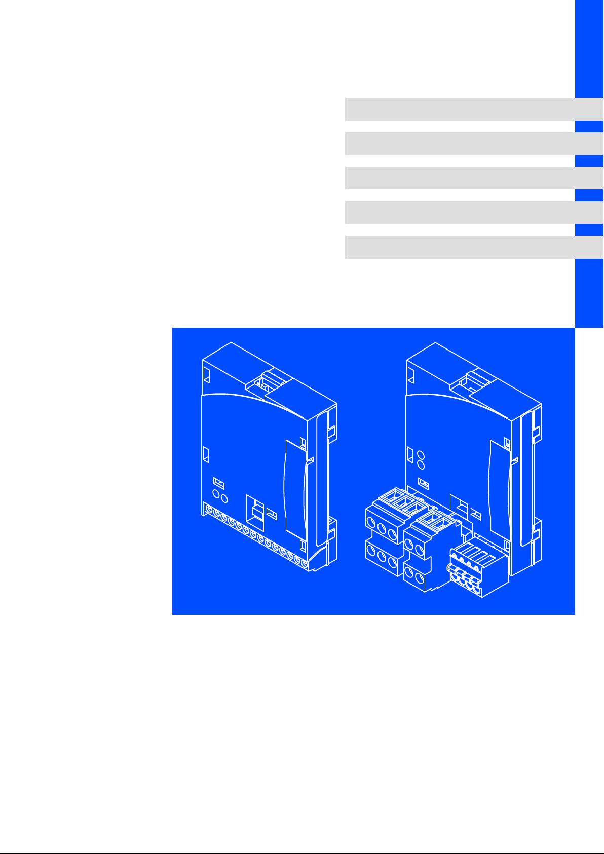
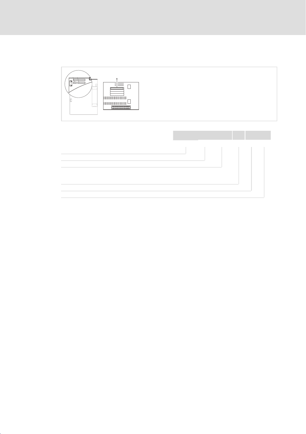
3.4 Connections and interfaces
E82ZAFPC001function module
E82ZAFPC001
0
ON
2
1
AABB
CN
+
VP
7
40 39 28 20 59
3
4
7
E82ZAFP004/AFX009
Pos. Description Detailed
DIP switch for activating the bus terminating resistor 40
Status of PROFIBUS communication (yellow LED)
Connection status to the standard device (green LED)
Terminal strip X3, connection for
l PROFIBUS
l Controller inhibit (CINH)
l External voltage supply
Nameplate 12
information
67
28
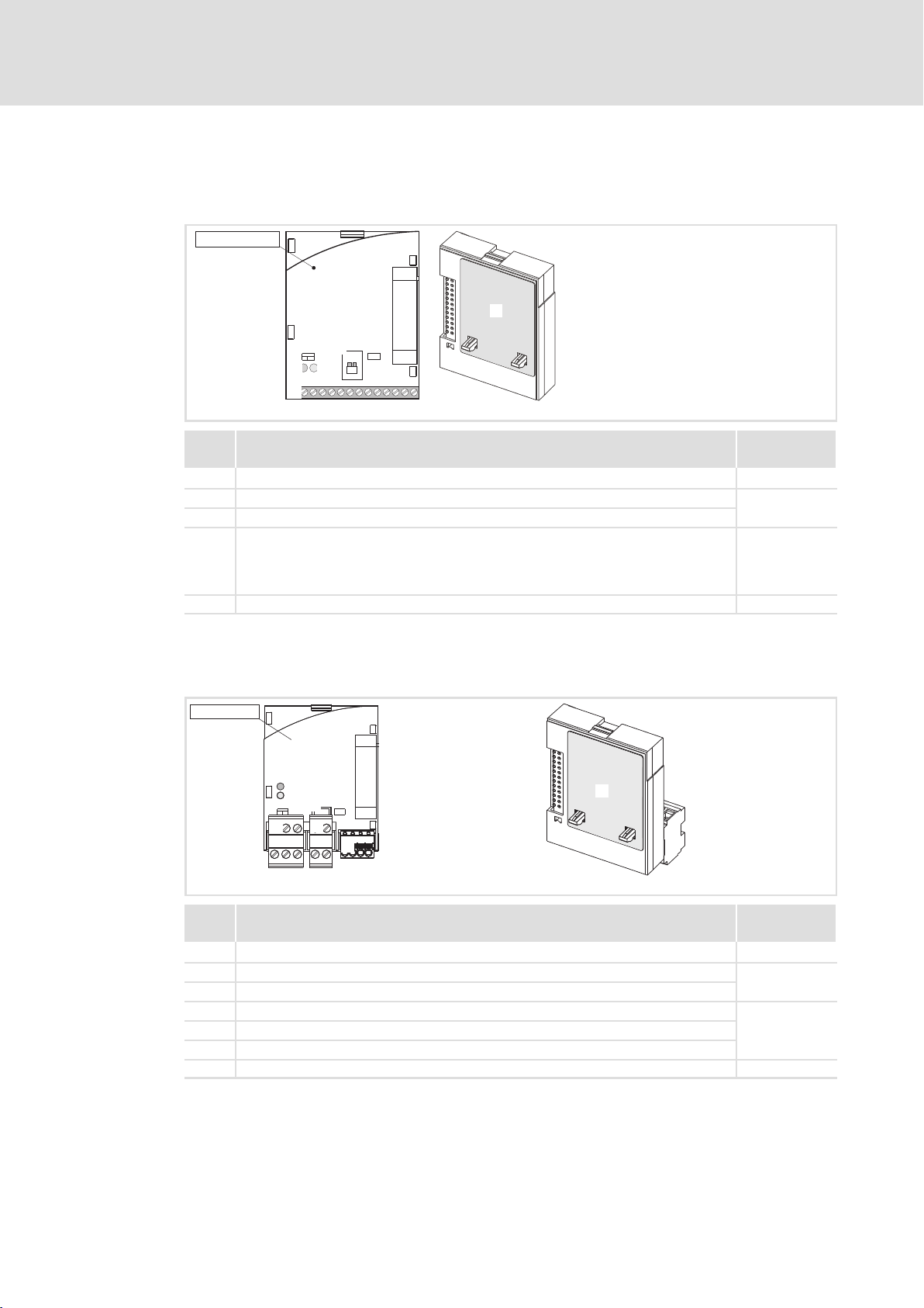
E82ZAFPC010 function module
E82ZAFPC010
3
1
2
0
4
6
5
E82ZAFP012/E82ZAFX015
14
Pos. Description Detailed
DIP switch for activating the bus terminating resistor 40
Status of PROFIBUS communication (yellow LED)
Connection status to the standard device (green LED)
Plug connector X3.1, connection for PROFIBUS
Plug connector X3.2, connection for external voltage supply
Plug connector X3.3, connection for controller inhibit (CINH)
Nameplate 12
information
67
29
EDS82ZAFPC010 EN 4.0
Page 15

4 Technical data
4.1 General data
Field Values
Order designation E82ZAFPC001 (coated)
PUO ID number 0x00DA
Communication profile
(DIN 19245 Part 1 and Part3)
Communication medium RS485
Drive profile l DRIVECOM profile "Drive technology 20" (can be switched off)
Network topology l Without repeaters: line
PROFIBUS stations Slave
Baud rate [kbps] 9.6 ... 12000 (automatic detection)
Process data words 1 ... 10 words
DP user data length 1 ... 10 process data words +
Max. number of bus devices l Standard: 32 (= 1 bus segment)
Max. cable length per bus
segment
External DC−voltage supply +24 V DC ±10 %, max. 80 mA
Technical data
General data
E82ZAFPC010 (PT design)
l PROFIBUS−DP−V0
l With repeaters: line or tree
(16 bits/word)
4 parameter data words
l With repeaters: 125
1200 m (depending on the baud rate and cable type used)
4
4.2 Operating conditions
Ambient conditions
Climate
Storage
Transport IEC/EN 60721−3−2 2K3 (−25 to +70 °C)
Operation Corresponding to the data of the Lenze standard device used (see documentation
Pollution EN 61800−5−1 Degree of pollution 2
Degree of protection IP20 (protection against accidental contact according to NEMA 250 type 1)
IEC/EN 60721−3−1 1K3 (−25 to +60 °C)
of the standard device).
EDS82ZAFPC010 EN 4.0
15
Page 16

4
Technical data
Protective insulation
4.3 Protective insulation
Danger!
Dangerous electrical voltage
If Lenze controllers are used on a phase earthed mains with a rated mains
voltage ³ 400 V, protection against accidental contact is not ensured without
implementing external measures.
Possible consequences:
ƒ Death or serious injury
Protective measures:
ƒ If protection against accidental contact is required for the control terminals
of the controller and the connections of the plugged device modules, ...
– a double isolating distance must exist.
– the components to be connected must be provided with the second
E82ZAFPC001function module
Protective insulation between bus and ... Type of insulation (according to EN 61800−5−1)
l Power section
– 8200 vector Reinforced insulation
– 8200 motec Reinforced insulation
– starttec Reinforced insulation
l Reference earth / PE (X3/7) Functional insulation
l External supply (X3/59) Functional insulation
l Terminal X3/20 Functional insulation
l Terminal X3/28 Functional insulation
isolating distance.
E82ZAFPC010 function module
Insulation between bus and ... Type of insulation (in accordance with EN 61800−5−1)
l 8200 vector power stage Reinforced insulation
l Reference earth / PE (X3.2/7, X3.3/7) Functional insulation
l External supply (X3.2/59) Functional insulation
l Supply for CINH (X3.3/20) Functional insulation
l Controller inhibit, CINH (X3.3/28) Functional insulation
16
EDS82ZAFPC010 EN 4.0
Page 17

Technical data
Connection terminals
4
4.4 Connection terminals
E82ZAFPC001function module
Terminal strip X3/
VP Level: 5 V (reference: GND3)
28 External supply of terminal with
20 DC voltage source for internal supply of controller inhibit (CINH)
59 External supply of function module with
E82ZAFPC010 function module
Terminal strip X3.2/
59
Terminal strip X3.3/
28 External supply of terminal with
20
Load capacity: I
U(ext.) = +12 V DC − 0% ... +30 V DC + 0%
U = + 20 V (reference: GND1),
= 20 mA
I
max
U(ext.) = +24 V DC ± 10%
External supply of function module with
U(ext.) = +24 V DC ± 10%
U(ext.) = +12 V DC − 0% ... +30 V DC + 0%
DC voltage source for internal supply of controller inhibit (CINH)
U = + 20 V (reference: GND1)
Load capacity: I
max
max
= 10 mA
= 20 mA
EDS82ZAFPC010 EN 4.0
17
Page 18

4
Technical data
Communication time
4.5 Communication time
The communication time is the time between the start of a request and the arrival of the
corresponding response.
The communication times depend on ...
ƒ the processing time in the controller
ƒ the transmission delay time
– the baud rate
– the telegram length
Processing time 8200vector / 8200motec / starttec
There are no interdependencies between parameter data and process data.
ƒ Parameter data: approx. 30 ms + 20 ms tolerance
ƒ Process data: approx. 3 ms + 2 ms tolerance
18
EDS82ZAFPC010 EN 4.0
Page 19
Technical data
Dimensions
4
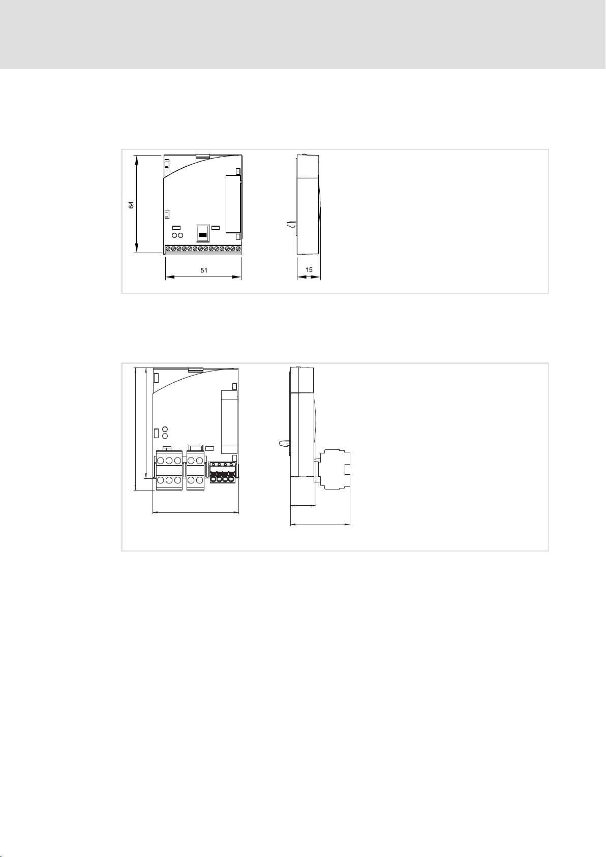
4.6 Dimensions
E82ZAFPC001function module
E82ZAFPC010 function module
E82ZAFL011B
All dimensions in mm
72
64
51
All dimensions in mm
15
30
E82ZAFP007
EDS82ZAFPC010 EN 4.0
19
Page 20

5
Installation
Mechanical installation
5 Installation
Danger!
Inappropriate handling of the function module and the standard device can
cause serious injuries to persons and damage to material assets.
Observe the safety instructions and residual hazards included in the
documentation of the standard device.
Stop!
The device contains components that can be destroyed by electrostatic
discharge!
Before working on the device, the personnel must ensure that they are free of
electrostatic charge by using appropriate measures.
5.1 Mechanical installation
Follow the notes given in the Mounting Instructions for the standard device for the
mechanical installation of the function module.
The Mounting Instructions for the standard device ...
ƒ are part of the scope of supply and are enclosed with each device.
ƒ provide tips to avoid damage provide tips to avoid damage through improper
handling.
ƒ describe the obligatory order of installation steps.
20
EDS82ZAFPC010 EN 4.0
Page 21

Wiring according to EMC (CE−typical drive system)
5.2 Electrical installation
5.2.1 Wiring according to EMC (CE−typical drive system)
For wiring according to EMC requirements observe the following points:
Note!
ƒ Separate control cables/data lines from motor cables.
ƒ Connect the shields of control cables/data lines at both ends in the case of
digital signals.
ƒ Use an equalizing conductor with a cross−section of at least 16mm
(reference:PE) to avoid potential differences between the bus nodes.
ƒ Observe the other notes concerning EMC−compliant wiring given in the
documentation for the standard device.
Wiring procedure
Installation
Electrical installation
5
2
1. Observe the bus topology, do not use any stubs.
2. Observe the notes and wiring instructions given in the documents for the control
system.
3. Only use cables corresponding to the listed specifications ( 24).
4. Observe the notes for the voltage supply of the module ( 25).
5. Activate the bus terminating resistors on the first and last physical bus device
( 40).
EDS82ZAFPC010 EN 4.0
21
Page 22
5
Installation
Electrical installation
Wiring with a host (master)
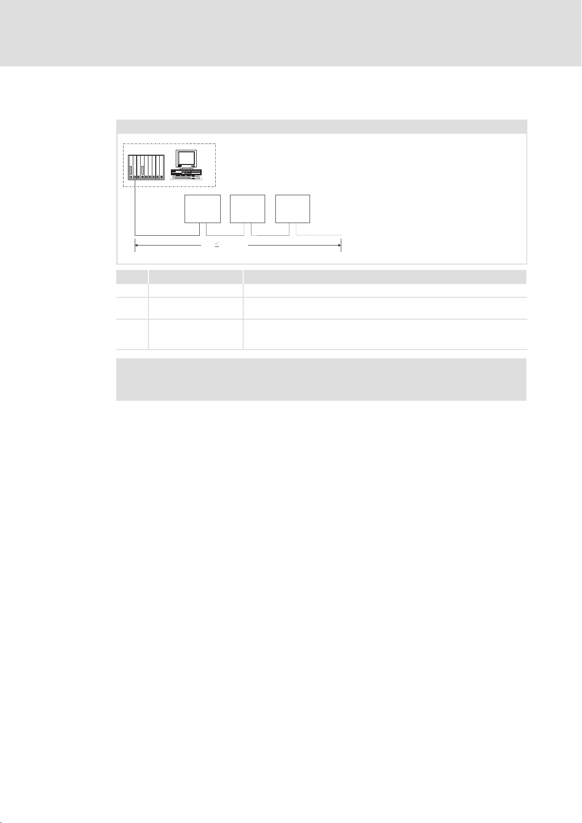
5.2.2 Wiring with a host (master)
Basic design of a PROFIBUS network with RS485 cabling without repeater
1
333
starttec
8200 vector
8200 motec
+
E82ZAFPC0xx
222
No. Element Note
1 Host E.g. PC or PLC with PROFIBUS master interface module
2 Bus cable Connects the PROFIBUS master interface module to the function modules.
3 PROFIBUS slave Applicable standard device ( 11)with function module
1200 m
0m
8200 vector
8200 motec
E82ZAFPC0xx
starttec
+
l The baud rate depends on the length of the bus cable ( 24).
l Activate bus terminating resistors at the first and last physical node
starttec
8200 vector
8200 motec
+
E82ZAFPC0xx
( 40).
E82ZAFP005
Note!
When using a repeater, max. 125 nodes can communicate via the PROFIBUS.
22
EDS82ZAFPC010 EN 4.0
Page 23
Installation
Electrical installation
Wiring with a host (master)
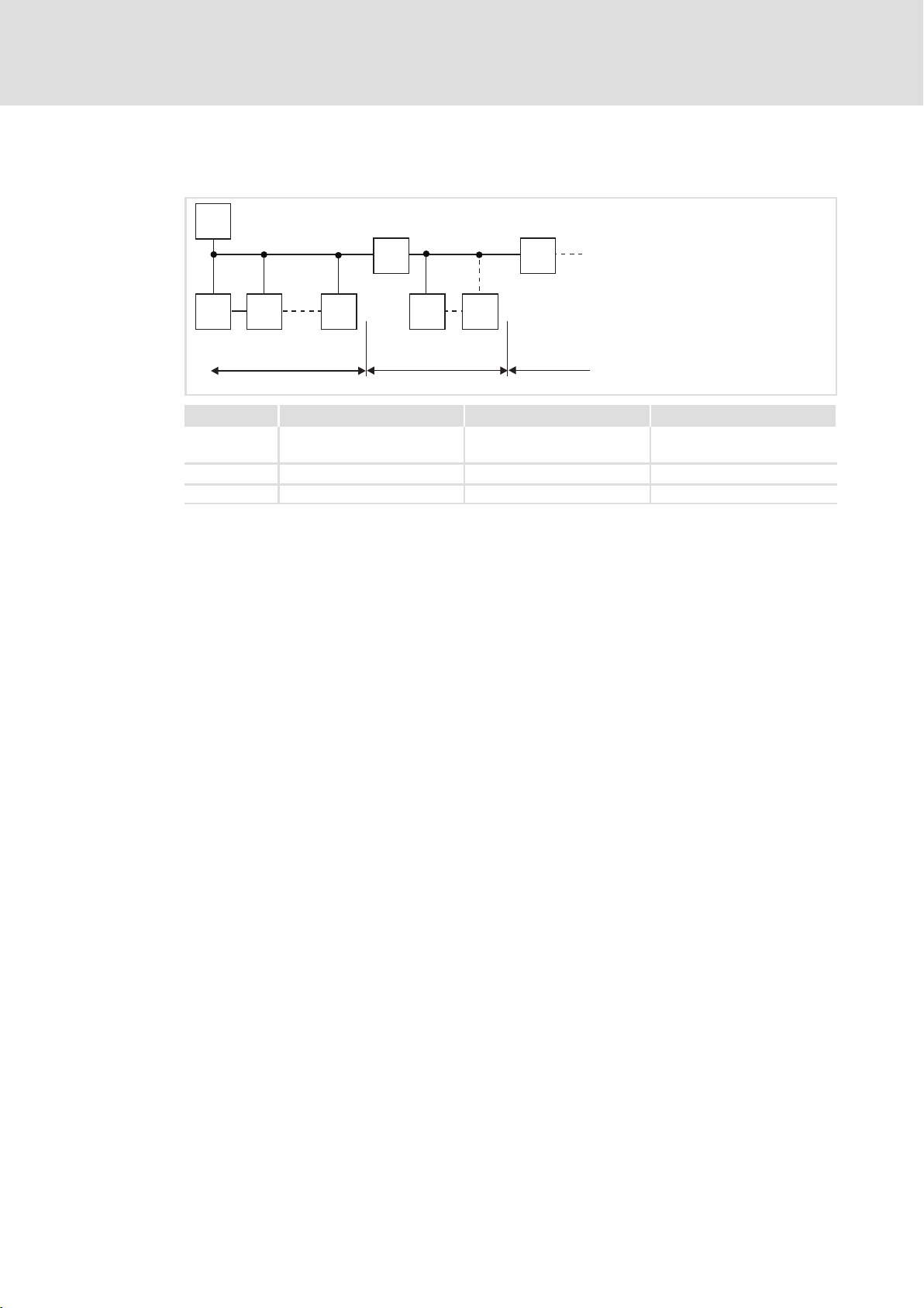
Number of bus devices
M
RR
SS S S S
123
Segment Master (M) Slave (S) Repeater (R)
11231
30
2 − 30 1
3 − 30 1
−
−
5
2133PFB004
Tip!
Repeaters do not have a device address. When calculating the maximum
number of bus devices, they reduce the number of devices by 1 on each side of
the segment.
Repeaters can be used to build up line and tree topologies. The maximum total
bus system expansion depends on ...
ƒ the baud rate used;
ƒ the number of repeaters used.
EDS82ZAFPC010 EN 4.0
23
Page 24

5
Installation
Electrical installation
Wiring with a host (master)
Specification of the transmission cable
Note!
Only use cables complying with the listed specifications of the PROFIBUS user
organisation.
Field Values
Specific resistance 135 ... 165 W/km, (f = 3 ... 20 MHz)
Capacitance per unit length £ 30 nF/km
Loop resistance < 110 W/km
Core diameter > 0.64 mm
Core cross−section > 0.34 mm
Cores Twisted double, insulated and shielded
2
Bus cable length
The length of the bus cable depends on the baud rate used:
Baud rate [kbps] Length [m]
9.6 ... 93.75 1200
187.5 1000
500 400
1500 200
3000 ... 12000 100
Note!
The baud rate depending on the data volume, cycle time, and number of nodes
should only be selected as high as required for the application.
Tip!
For high baud rates we recommend to consider the use of optical fibres.
Advantages of optical fibres:
ƒ On the transmission path external electromagnetic interference remains
ineffective.
ƒ Bus lengths of several kilometres are also possible with higher baud rates.
The bus length
– is irrespective of the baud rate.
– depends on the optical fibre used.
24
EDS82ZAFPC010 EN 4.0
Page 25

Installation
Electrical installation
Voltage supply
5
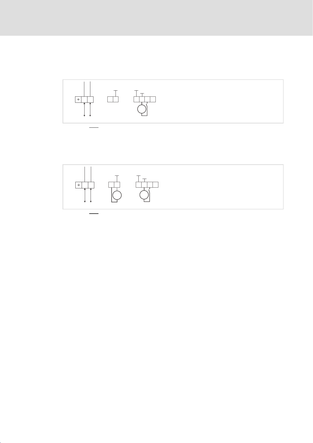
5.2.3 Voltage supply
Internal DC voltage supply
E82ZAFPC001function module
The internal voltage is provided at terminal X3/20. It serves to supply the controller inhibit
(CINH).
+5V
B
AVP
+
X3
T/R(A) T/R(B) T/R(A) T/R(B)
CN
E82ZAFPC010 function module
The internal voltage is provided at terminal X3.3/20. It serves to supply the controller
inhibit (CINH).
T/R(A) T/R(B)
A
X3.1 X3.2
B
GND1
+20V
7
20 59
2839
BA
GND3
40
GND1
7
GND2
The min. wiring requirements for operation
GND1
720
59
X3.3
GND1
GND2
+20V
28397
E82ZAFP001
T/R(A) T/R(B)
E82ZAFP011
The min. wiring requirements for operation
EDS82ZAFPC010 EN 4.0
25
Page 26

5
Installation
Electrical installation
Voltage supply
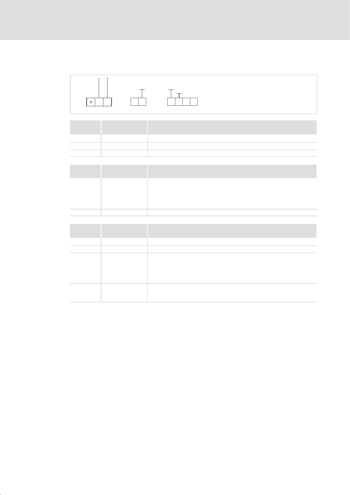
External voltage supply
Note!
Always use a separate power supply unit in every control cabinet and safely
separate it according to EN 61800−5−1 ("SELV"/"PELV") in the case of external
voltage supply and larger distances between the control cabinets.
External voltage supply of the function module is required if communication via the
fieldbus is to be maintained even when the power supply of the standard device fails.
Note!
With external voltage supply of the function module, the active bus
terminating resistor is fed independently of the operation of the standard
device. In this way, the bus system remains active even when the standard
device is switched off or fails.
E82ZAFPC001function module
External voltage supply with one voltage source for
ƒ X3/28 (controller inhibit (CINH))
GND1
+20V
7
20 59
2839
B
AVP
X3
+
CN
T/R(A) T/R(B) T/R(A) T/R(B)
GND1
GND3
+5V
GND2
7
BA
40
_
+
The min. wiring requirements for operation
External voltage supply with two voltage sources for
1. X3/28 (controller inhibit (CINH))
2. X3/59 (function module)
+20V
GND1
720
59
_
X3
GND1
GND2
+5V
A
+
VP
B
CN
GND3
40
BA
28397
_
E82ZAFP002
26
T/R(A) T/R(B) T/R(A) T/R(B)
The min. wiring requirements for operation
+
+
E82ZAFP003
EDS82ZAFPC010 EN 4.0
Page 27
E82ZAFPC010 function module
External voltage supply with one voltage source for
ƒ X3.3/28 (controller inhibit (CINH))
T/R(A) T/R(B)
A
X3.1 X3.2
B
GND1
720
59
X3.3
GND1
GND2
_
+20V
28397
Installation
Electrical installation
Voltage supply
5
T/R(A) T/R(B)
+
The min. wiring requirements for operation
External voltage supply with two voltage sources for
1. X3.3/28 (controller inhibit (CINH))
2. X3.2/59 (function module)
T/R(A) T/R(B)
A
X3.1 X3.2
T/R(A) T/R(B)
B
GND1
720
59
The min. wiring requirements for operation
GND1
GND2
+20V
X3.3
_
+
28397
_
+
E82ZAFP012
E82ZAFP013
EDS82ZAFPC010 EN 4.0
27
Page 28

5
Installation
Electrical installation
Terminal assignment
5.2.4 Terminal assignment
E82ZAFPC001function module
B
AVP
CN
Designation Function / level
PES Additional HF−shield termination
+
X3
Terminal
X3/
A T/R(A) RS485 data line A
B T/R(B) RS485 data line B
CN CNTR For function see PROFIBUS standard *)
VP For function see PROFIBUS standard *)
40 GND3 Reference potential for PROFIBUS network *)
7 GND1 Reference potential for X3/20
39 GND2 Reference potential for controller inhibit (CINH) at X3/28
28 CINH Controller inhibit
20 DC voltage source for internal supply of controller inhibit (CINH)
59 External DC voltage supply for the function module
*) E.g. for repeater connection
+5V
+20V
20 59
GND1
7
E82ZAFP001
GND1
GND3
GND2
7
BA
40
2839
l Level during data transmission: CNTR = HIGH
(+5 V DC, reference:GND3)
l U = +5 V DC (reference:GND3)
l I
= 10 mA
max
l Start = HIGH (+12 ... +30 V DC)
l Stop = LOW (0 ... +3 V DC)
(reference: GND2)
l +20 V DC (reference: GND1)
l I
= 20 mA
max
l +24VDC±10% (reference: GND1)
l Current consumption on 24 V DC: 80 mA
The current for looping through the supply voltage to other nodes via
terminal 59 must be max. 3A.
28
EDS82ZAFPC010 EN 4.0
Page 29
E82ZAFPC010 function module
T/R(A) T/R(B)
GND1
720
A
X3.1 X3.2
B
59
X3.3
GND1
GND2
Installation
5
Electrical installation
Terminal assignment
+20V
28397
E82ZAFP011
Terminal
X3.1/
A T/R(A) RS485 data line A
B T/R(B) RS485 data line B
Terminal
X3.2/
59 External DC voltage supply for the function module
7 GND1 Reference potential for X3.3/20
Terminal
X3.3/
7 GND1 Reference potential for X3.3/20
39 GND2 Reference potential for controller inhibit (CINH) at X3.3/28
28 CINH Controller inhibit
20 DC voltage source for external supply of controller inhibit (CINH)
Designation Function / level
PES Additional HF shield termination
Designation Function / level
l +24VDC±10% (reference: GND1)
l Current consumption on 24 V DC: 80 mA
The current for looping through the supply voltage to other nodes via
terminal 59 must be max. 3A.
Designation Function / level
l Input resistance: 3.3 kW
l Start = HIGH (+12 ... +30 V)
l Stop = LOW (0 ... +3 V)
(reference: GND2)
l +20 V (reference: GND1)
l I
= 10 mA
max
EDS82ZAFPC010 EN 4.0
29
Page 30

5
Installation
Electrical installation
Cable cross−sections and screw−tightening torques
5.2.5 Cable cross−sections and screw−tightening torques
Range Values
Electrical connection Terminal strip with screw connection
Possible connections
rigid:
flexible:
Tightening torque 0.22 ... 0.25 Nm (1.9 ... 2.2 lb−in)
Bare end 5 mm
Field Values
Electrical connection Plug connector with double screw connection
Possible connections
rigid:
flexible:
Tightening torque 0.5 ... 0.6 Nm (4.4 ... 5.3 lb−in)
Stripping length 10 mm
2
1.5 mm
without wire end ferrule
1.0 mm
with wire end ferrule, without plastic sleeve
0.5 mm
with wire end ferrule, with plastic sleeve
0.5 mm
1.5 mm
without wire end ferrule
1.5 mm
with wire end ferrule, without plastic sleeve
1.5 mm
with wire end ferrule, with plastic sleeve
1.5 mm
(AWG 16)
2
(AWG 18)
2
(AWG 20)
2
(AWG 20)
2
(AWG 16)
2
(AWG 16)
2
(AWG 16)
2
(AWG 16)
Field Values
Electrical connection 2−pin plug connector with spring connection
Possible connections
rigid:
1.5 mm
2
(AWG 16)
flexible:
without wire end ferrule
2
1.5 mm
with wire end ferrule, without plastic sleeve
1.5 mm
with wire end ferrule, with plastic sleeve
1.5 mm
(AWG 16)
2
(AWG 16)
2
(AWG 16)
Stripping length 9 mm
30
EDS82ZAFPC010 EN 4.0
Page 31

5.2.6 Use of plug connectors
Stop!
Observe the following to prevent any damage to plug connectors and
contacts:
ƒ Only pug in / unplug the plug connectors when the controller is
disconnected from the mains.
ƒ Wire the plug connectors before plugging them in.
ƒ Unused plug connectors must also be plugged in.
Use of plug connectors with spring connection
Installation
Electrical installation
Use of plug connectors
5
E82ZAFX013
EDS82ZAFPC010 EN 4.0
31
Page 32

5
Installation
Bus cable length
Use of plug connectors
5.3 Bus cable length
Max. possible bus cable length
The following bus cable lengths are possible in dependence on the baud rate and the cable
used:
Baud rate [kbit/s] Thin Cable Thick Cable
125
250 250 m
500 100 m
When using both, Thick" and Thin" cables, the maximum cable lengths are to be selected
according to the baud rate:
Baud rate [kbit/s] Bus cable length
125 L
250 L
500 L
100 m
= 500 m = L
max
= 250 m = L
max
= 100 m = L
max
thick
thick
thick
+ 5 L
+ 2.5 L
+ L
thin
500 m
thin
thin
32
EDS82ZAFPC010 EN 4.0
Page 33

6 Commissioning
During commissioning, system−dependent data as e.g. motor parameters, operating
parameters, responses and parameters for fieldbus communication are selected for the
controller.
In Lenze devices, this is done via codes. The codes are stored in numerically ascending order
in the Lenze controllers and in the plugged−in communication/function modules.
In addition to these configuration codes, there are codes for diagnosing and monitoring
the bus devices.
6.1 Before switching on
Stop!
Before switching on the standard device with the function module for the first
time, check...
ƒ the entire wiring for completeness, short circuit, and earth fault.
ƒ whether the integrated bus terminating resistor is activated at the first and
last physical node ( 40).
Commissioning
Before switching on
6
EDS82ZAFPC010 EN 4.0
33
Page 34

6
Commissioning
Commissioning steps
6.2 Commissioning steps
Note!
Do not change the setting sequence.
Step−by−step commissioning of the function module with the DRIVECOM device control is
described below.
Step Description Detailed
1. Configure master system (master) for communication with the function
2. Inhibit standard device via terminal 28 (CINH).
3.
4. Activate bus terminating resistor via DIP switch = ONfor the first and last
5. A Set node address via ...
6.
7. Select function module as source for control commands and setpoints.
8.
module.
l Set terminal 28 to LOW level.
l Later the standard device can be inhibited and enabled via the bus.
Connect mains voltage and, if available, separate voltage supply of the
function module.
l The standard device will be ready for operation after approx. 1 second.
l Controller inhibit (CINH) is active.
Response
l The green LED "Connection status to the standard device" at the front of
the function module is lit (only visible in the case of 8200 vector).
l Keypad: (if plugged in)
node.
l Lenze setting: OFF
– C1509
After a parameter set transfer the address has to be reassigned.
B Switch off the voltage supply of the function module and the standard
device and then switch it on again in order to accept changed settings.
The address that is modified via keypad becomes effective immediately.
Now you can communicate with the standard device, i. e. you can read all
codes and adapt all writable codes to your application.
Response
The yellow LED on the function module is blinking when the PROFIBUS is
active.
l Set C0005 = 200.
– A preconfiguration for operation with the function module is carried
out.
– Control words and status words are already linked.
Assign process data output words (POW) of the master to process data input
words of the standard device via C1511.
Lenze setting:
POW1: DRIVECOM control word (DRIVECOM CTRL)
POW2:
POW3:
POW4:
POW5:
POW6:
POW7:
POW8:
Setpoint1 (NSET1−N1)
Setpoint2 (NSET1−N2)
Additional setpoint (PCTRL1−NADD)
Actual process controller value (PCTRL1−ACT)
Process controller setpoint (PCTRL1−SET1)
Reserved (FIF−RESERVED)
Torque setpoint or torque limit (MCTRL1−MSET)
information
36
Documentation of
the standard device
42
67
40
Documentation of
the standard device
Documentation of
the standard device
67
PROFIBUS
communication
manual
34
EDS82ZAFPC010 EN 4.0
Page 35

Commissioning
Commissioning steps
6
DescriptionStep
POW9: PWM voltage (MCTRL1−VOLT−ADD)
POW10: PWM angle (MCTRL1−PHI−ADD)
9.
10.
11. Enable standard device via terminal 28 (CINH).
12. Enter the setpoint.
13. Change to the READY TO START status:
14. The standard device is in the READY TO START status.
15. Change to the OPERATION ENABLED status.
16. Now the drive starts up.
Assign process data output words of the standard device to the process data
input words (PIW) of the master via C1510.
Lenze setting:
PIW1: DRIVECOM status word (DRIVECOM STAT)
Output frequency with slip (MCTRL1−NOUT+SLIP)
PIW2:
PIW3:
Output frequency without slip (MCTRL1−NOUT)
PIW4:
Apparent motor current (MCTRL1−IMOT)
PIW5:
Actual process controller value (PCTRL1−ACT)
PIW6:
Process controller setpoint (PCTRL1−SET1)
PIW7:
Process controller output (PCTRL1−OUT)
PIW8:
Controller load (MCTRL1−MOUT)
PIW9:
DC−bus voltage (MCTRL1−DCVOLT)
PIW10:
Enable process output data via C1512 = 65535.
l Only required if C1511 has been changed.
l Deactivate process data words that are not used by setting the respective
subcode of code C1511 to 0.
l The value in C1512 is volatile, and all process data are enabled after every
switch−on.
l Set terminal 28 to HIGH level.
l The master transmits the setpoint via the process data output word
selected.
l The master transmits the DRIVECOM control word:
0000 0000 0111 1110
l The master receives the DRIVECOM status word:
xxxx xxxx x01x 0001
l The master transmits DRIVECOM control word:
0000 0000 0111 1111
Ramp function generator input (NSET1−RFG1−IN)
bin
bin
bin
(007E
(007F
hex
hex
).
).
Detailed
information
PROFIBUS
communication
manual
PROFIBUS
communication
manual
EDS82ZAFPC010 EN 4.0
35
Page 36

6
6.3 Configuring the host system (master)
Commissioning
Configuring the host system (master)
The host must be configured before communication with the communication module is
possible.
Master settings
For configuring the PROFIBUS, the device data base file (GSE file) of the communication
module has to be imported into the configuring software of the master.
Tip!
The GSE file can be downloaded from www.Lenze.com.
36
EDS82ZAFPC010 EN 4.0
Page 37

Commissioning
Configuring the host system (master)
Device data base file
The following configurations are saved in the device data base file LENZ00DA.GSE:
6
Parameter data
Modules in LENZ00DA.GSE
PAR (Cons.) + PZD (n Words)
PAR (Cons.) + PZD (n Words Cons.)
PAR + PZD (n Words)
PZD (n Words) Without parameter data channel n words n words
PZD (n Words Cons.) Without parameter data channel n words n words
n = 1 ... 10
without/with consistency
Without With Without With
·
·
·
Process data
without/with consistency
n words 4 + n words
n words 4 + n words
n words 4 + n words
Assigned
I/O memory
Note!
Device control via FIF status/control word
Device control is only possible if the DRIVECOM status machine (Lenze setting)
is switched off.
ƒ Set C1510 /1 (PIW1) to the value 1":
FIF status word 1 (FIF−STAT1).
ƒ Set C1511 /1 (POW1) to the value 1":
FIF control word 1 (FIF−CTRL1).
ƒ Set C1512 to 65535" to reenable process output words.
For Lenze codes see ( 69)
Tip!
Use overall consistency
ƒ We recommend to use exclusively configurations with consistency for the
parameter data channel to avoid data conflicts between PROFIBUS−DP
master and host CPU.
ƒ Please note that the processing of consistent data varies between hosts.
This must be considered in the PROFIBUS−DP application program.
ƒ Detailed description of consistency: ( 87)
EDS82ZAFPC010 EN 4.0
37
Page 38

6
6.3.1 Adapting device controls
Commissioning
Configuring the host system (master)
Adapting device controls
ƒ Lenze device control
– Set C1511/1 (POW1) = 1 ð FIF control word 1 (FIF−CTRL1)
– Set C1510/1 (PIW1) = 1 ð FIF status word 1 (FIF−STAT1)
ƒ Device control via DRIVECOM
– Set C1511/1 (POW1) = 17 ð DRIVECOM control word (DRIVECOM−CTRL)
– Set C1510/1 (PIW1) = 18 ð DRIVECOM status word (DRIVECOM−STAT)
For detailed information about the configuration of process data, see chapter "Process
data transfer", 43)
Tip!
Use overall consistency
ƒ Please observe that the processing of consistent data varies between hosts.
This must be taken into account in the PROFIBUS application program.
ƒ A detailed description of consistency can be found in the appendix ( 86)
38
EDS82ZAFPC010 EN 4.0
Page 39

Commissioning
Configuring the host system (master)
Defining the user data length
6
6.3.2 Defining the user data length
The user data length is defined during the initialisation phase of the PROFIBUS. It is
possible to configure up to 10 process data words (see chapter "Process data transfer",
43).
Optionally you can activate a parameter data channel. If the parameter data channel is
active, it additionally occupies 4 words of the process input and process output data.
ƒ PIW: process data input word (process data from standard device to master)
ƒ POW: process data output word (process data from master to standard device)
The user data lengths for process input data and process output data are identical. The
selection takes place via identification bytes in the configuration software for the
PROFIBUS system.
Parameter data channel Process data channel
Without /
with
Without −
With
Identification / user data length Identification / user data length
l Identification: F3
l User data length: 4 words
(word 1 ... word 4)
hex
(243)
l Identification
hex
hex
hex
... F9
hex
... F9
... 79
... 79
– without consistency: 70
– with consistency: F0
l User data length: 1 ... 10 words
(POW1/PIW1 ... POW10/PIW10)
l Identification
– without consistency: 70
– with consistency: F0
l User data length: 1 ... 10 words
(POW1/PIW1 ... POW10/PIW10)
(112 ... 121)
hex
(240 ... 249)
hex
(112 ... 121)
hex
(240 ... 249)
hex
General structure of the identification byte
MSB LSB
7 6 5 4 3 2 1 0
Data length
00 1 byte or 1 word
...
15 16 bytes or 16 words
Input/output
00 Special identification format
01 Input
10 Output
11 Input and output
Length/format
0 Byte
1 Word
Consistency
0 Byte or word
1 Total length
EDS82ZAFPC010 EN 4.0
39
Page 40

6
Commissioning
Activating the bus terminating resistor
6.4 Activating the bus terminating resistor
0
ON
1
7
AABB
VP
CN
+
DIP switch
40 39 28 20 59
7
E82ZAFPC004 E82ZAFPC004
DIP switch = ON Integrated active bus terminating resistor is switched on
DIP switch = OFF Integrated active bus terminating resistor is switched off
0
40
EDS82ZAFPC010 EN 4.0
Page 41

Commissioning
Setting the node address
6
6.5 Setting the node address
To address the basic devices, each device (station) is allocated a different node address in
the PROFIBUS−DP network.
Valid address range: 3 126
(Lenze setting: 3)
The node address can be selected freely via code C1509.
It can be set with
ƒ the keypad,
ƒ the PC / communication module, type 2102 LECOM, or
ƒ the class 2 master.
EDS82ZAFPC010 EN 4.0
41
Page 42

6
Commissioning
Connecting the mains voltage
6.6 Connecting the mains voltage
Note!
If the external voltage supply of the function module is used, the supply must
be switched on as well.
ƒ The standard device will be ready for operation approx. 1 s after switching on the
supply voltage.
ƒ Controller inhibit is active.
ƒ The green LED at the front of the function module is lit (only visible in the case of the
8200 vector frequency inverter).
Protection against uncontrolled start−up
Note!
Establishing communication
For establishing communication via an externally supplied function module,
the standard device must be switched on as well.
ƒ After communication has been established, the externally supplied module
is independent of the power on/off state of the standard device.
Protection against uncontrolled start−up
After a fault (e.g. short−term mains failure), a restart of the drive is not always
wanted and − in some cases − even not allowed.
The restart behaviour of the controller can be set in C0142:
ƒ C0142 = 0 (Lenze setting)
– The controller remains inhibited (even if the fault is no longer active).
– The drive starts in a controlled mode by explicitly enabling the controller:
LOW−HIGH edge at terminal 28 (CINH)
ƒ C0142 = 1
– An uncontrolled restart of the drive is possible.
42
EDS82ZAFPC010 EN 4.0
Page 43

7 Process data transfer
PROFIBUS transmits parameter data and process data between the host (master) and the
controllers connected to the bus (slaves). Depending on their time−critical nature, the data
are transmitted via different communication channels.
ƒ Process data are transmitted via the process data channel.
ƒ Process data serve to control the drive controller.
ƒ The transmission of process data is time−critical.
ƒ Process data are cyclically transferred between the host and the controllers
(continuous exchange of current input and output data).
ƒ The host can directly access the process data. In the PLC, for instance, the data are
directly assigned to the I/O area.
ƒ With the function module a maximum of 10 process data words (16 bits/word) can
be exchanged in each direction.
Process data transfer 7
ƒ Process data are not stored in the controller.
ƒ Process data are, for instance, setpoints, actual values, control words and status
words.
Note!
Observe the direction of the information flow!
ƒ Process input data (Rx data):
– Process data from controller (slave) to host (master)
ƒ Process output data (Tx data):
– Process data from host (master) to controller (slave)
EDS82ZAFPC010 EN 4.0
43
Page 44

7
7.1 Lenze device control
Process data transfer
Lenze device control
Process output data configuration
Codes C1510 (process input data) and C1511 (process output data) can be used to freely
assign up to 10 process data words of the PROFIBUS to the process data words of the
controller.
Note!
ƒ The PROFIBUS master sends process output data in up to 10 process data
output words (POW) to the slave.
ƒ The PROFIBUS master receives process input data in up to 10 process data
input words (PIW) from the slave.
7.1.1 Process output data configuration
The assignment of up to 10 process data output words (POW) of the master to bit control
commands, actual values or setpoints of the controller can be freely configured via code
C1511.
Note!
ƒ The assignment of control words of different device controls is not
permitted.
ƒ If C1511 is changed, the process output data are automatically inhibited to
ensure data consistency.
ƒ Via C1512 you can re−enable individual or all POWs.
ƒ To activate the DRIVECOM device control, assign the DRIVECOM control word to a
POW (C1511/x = 17).
– The DRIVECOM control word is mapped to the FIF control word 1.
– The controller operates in compliance with the DRIVECOM state machine. ( 51).
ƒ You can set up an extended Lenze device control using the FIF control words ( 47).
44
EDS82ZAFPC010 EN 4.0
Page 45

Process data transfer
Lenze device control
Process output data configuration
C1511:
Configuration of process output data
Possible settings
Code Subcode Index
C1511 23064d =
1 (POW1) 17
2 (POW2) 3
3 (POW3) 4
4 (POW 4) 5
5 (POW 5) 6
6 (POW 6) 7
7 (POW 7) 8
8 (POW 8) 9
9 (POW 9) 10
10 (POW 10) 11
5A18
The process data output words (POW) of the master can be freely assigned to bit control
commands or setpoints of the controller via C1511.
Lenze Selection
h
Data type
FIX32
see table below
7
Selection Scaling
1 FIF control word 1 (FIF−CTRL1) 16 bits
2 FIF control word 2 (FIF−CTRL2) 16 bits
3 Setpoint 1 (NSET1−N1) ±24000 º ±480 Hz
4 Setpoint 2 (NSET1−N2) ±24000 º ±480 Hz
5 Additional setpoint (PCTRL1−NADD) ±24000 º ±480 Hz
6 Actual process controller value (PCTRL1−ACT) ±24000 º ±480 Hz
7 Process controller setpoint (PCTRL1−SET1) ±24000 º ±480 Hz
8 Reserved
9 Torque setpoint/torque limit value (MCTRL1−MSET) 214 º100 % rated motor torque
10 PWM voltage (MCTRL1−VOLT−ADD)
11 PWM angle (MCTRL1−PHI−ADD)
12 Reserved
13 FIF−IN.W1 16 bits or 0 ... 65535
14 FIF−IN.W2 16 bits or 0 ... 65535
15 FIF−IN.W3 0 ... 65535
16 FIF−IN.W4 0 ... 65535
17 DRIVECOM control word (DRIVECOM−CTRL) 16 bits
For special applications only.
System manual for 8200 vector
EDS82ZAFPC010 EN 4.0
45
Page 46

7
Process data transfer
Lenze device control
Process output data configuration
POW1 POW1
POW2 POW2
POW3 POW3
POW4 POW4
POW5 POW5
POW6 POW6
PROFIBUS
POW7 POW7
POW8 POW8
POW9 POW9
POW10 POW10
A
B
CN
C1511/1 = 17
C1511/2 = 3
C1511/3 = 4
C1511/4 = 5
C1511/5 = 6
C1511/6 = 7
C1511/7 = 8
C1511/8 = 9
C1511/9 = 10
C1511/10 = 11
Byte 35
Byte 36
Byte 33
Byte 34
DRIVECOM-CTRL PROFIdrive-CTRL
Byte 1
FIF-CTRL1
Byte 2
Byte 3
FIF-CTRL2
Byte 4
Byte 5,6
Byte 7, 9
Byte 9, 10
Byte 11, 12
Byte 13, 14
Byte 15,16
Byte 17, 18
Byte 19, 20
Byte 21, 22
Byte 23, 24
FIF-IN.W1
Byte 25,26
FIF-IN.W2
Byte 27, 28
FIF-IN.W3
Byte 29,30
FIF-IN.W4
Byte 31,32
CTRL.B0
CTRL.B1
CTRL.B2
…
CTRL.B13
CTRL.B14
CTRL.B15
CTRL.B0
CTRL.B1
CTRL.B2
…
CTRL.B13
CTRL.B14
CTRL.B15
FIF-CTRL.B0
FIF-CTRL.B1
FIF-CTRL.B2
FIF-CTRL.B3
…
FIF-CTRL.B4
FIF-CTRL.B5
FIF-CTRL.B6
FIF-CTRL.B7
FIF-CTRL.B8
FIF-CTRL.B9
FIF-CTRL.B10
FIF-CTRL.B11
…
FIF-CTRL.B12
FIF-CTRL.B13
FIF-CTRL.B14
FIF-CTRL.B15
FIF-CTRL.B16
FIF-CTRL.B17
FIF-CTRL.B18
FIF-CTRL.B19
FIF-CTRL.B20
FIF-CTRL.B21
FIF-CTRL.B22
FIF-CTRL.B23
FIF-CTRL.B24
FIF-CTRL.B25
FIF-CTRL.B26
FIF-CTRL.B27
FIF-CTRL.B28
FIF-CTRL.B29
FIF-CTRL.B30
FIF-CTRL.B31
16 bits
16 bits
16 bits
16 bits
16 bits
16 bits
16 bits
16 bits
16 bits
16 bits
16 bits
16 bits
16 bits
16 bits
QSP
CINH
TRIP-SET
TRIP-RESET
…
FIF-IN.W1.B0 … FIF-IN.W1.B15
FIF-IN.W2.B0 … FIF-IN.W2.B15
FIF-IN
DCTRL
DCTRL
FIF-RESERVED
FIF-RESERVED
FIF-RESERVED
FIF-RESERVED
FIF-RESERVED
FIF-RESERVED
FIF-RESERVED
FIF-RESERVED
FIF-RESERVED
FIF-RESERVED
FIF-IN.W1
FIF-IN.W2
FIF-IN.W3
FIF-IN.W4
FIF-OUT
C0410/1 = 200
C0410/2 = 200
C0410/3 = 200
C0410/4 = 200
C0410/5 = 200
C0410/6 = 200
C0410/7 = 200
C0410/8 = 200
C0410/9 = 200
C0410/10 = 200
C0410/11 = 200
C0410/12 = 200
C0410/13 = 200
C0410/14 = 200
C0410/15 = 200
C0410/17 = 200
C0410/18 = 200
C0410/19 = 200
C0410/20 = 200
C0410/21 = 200
C0410/22 = 200
C0410/23 = 200
C0410/24 = 200
C0412/1 = 200
C0412/2 = 200
C0412/3 = 200
C0412/4 = 200
C0412/5 = 200
C0412/6 = 200
C0412/7 = 200
C0412/8 = 200
C0412/9 = 200
NSET1-JOG1/3
NSET1-JOG2/3
DCTRL1-CW/CCW
DCTRL1-QSP
NSET1-RFG1-STOP
NSET1-RFG1-0
MPOT1-UP
MPOT1-DOWN
RESERVED
DCTRL1-CINH
DCTRL1-TRIP-SET
DCTRL1-TRIP-RESET
DCTRL1-PAR2/4
DCTRL1-PAR3/4
MCTRL1-DCB
DCTRL1-H/RE
PCTRL1-I-OFF
PCTRL1-OFF
RESERVED
PCTRL1-STOP
DCTRL1-CW/QSP
DCTRL1-CCW/QSP
DFIN1-ON
NSET1-N1
NSET1-N2
PCTRL1-NADD
PCTRL1-SET1
PCTRL1-ACT
MCTRL1-MSET
RESERVED
MCTRL1-VOLT-ADD
MCTRL1-PHI-ADD
C0410/x = 30 … 45
C0415/x = 60 … 75
C0417/x = 60 … 75
C0418/x = 60 … 75
C0412/x = 20
C0419/x = 50
C0421/x = 50
C0410/x = 50 … 65
C0415/x = 80 … 95
C0417/x = 80 … 95
C0418/x = 80 … 95
C0412/x = 21
C0419/x = 51
C0421/x = 51
C0412/x = 22
C0419/x = 52
C0421/x = 52
C0412/x = 23
C0419/x = 53
C0421/x = 53
46
Fig. 7−1 Free configuration of the 10 PROFIBUS process output words
8200vec512
EDS82ZAFPC010 EN 4.0
Page 47

Process data transfer
Lenze device control
Process output data configuration
FIF control word 1 (FIF−CTRL1) FIF control word 2 (FIF−CTRL2)
Bit Assignment Bit Assignment
0 / 1 JOG values (NSET1−JOG2/3 | NSET1−JOG1/3) 0 Manual/remote changeover (DCTRL1−H/Re)
Bit 1 0
0001C0046 active
1101JOG2 (C0038) active
JOG1 (C0037) active
JOG3 (C0039) active
2 Current direction of rotation (DCTRL1−CW/CCW) 2 Switch off process controller (PCTRL1−OFF)
01Not inverted
Inverted
3 Quick stop (QSP) (FIF−CTRL1−QSP)
01Not active
Active (deceleration via QSP ramp C0105)
4 Stop ramp function generator (NSET1−RFG1−STOP) 4 Stop process controller (PCTRL1−STOP)
01Not active
Active
5 Ramp function generator input = 0 (NSET1−RFG1−0) 5 CW rotation/quick stop (QSP) (DCTRL1−CW/QSP)
01Not active
Active (deceleration via C0013)
6 UP function of motor potentiometer (MPOT1−UP) 6 CCW rotation/quick stop (QSP) (DCTRL1−CCW/QSP)
01Not active
Active
7 DOWN function of motor potentiometer (MPOT1−DOWN) 7 X3/E1 is digital frequency input (DFIN1−ON)
01Not active
Active
8
Reserved
9 Controller inhibit (FIF−CTRL1−CINH) 9
01Controller enabled
Controller inhibited
10 External fault (FIF−CTRL1−TRIP−SET) 10
11 Reset fault (FIF−CTRL1−TRIP−RESET)
0 Þ 1 Bit change resets TRIP
12 / 13 Parameter set changeover
(DCTRL1−PAR3/4 | DCTRL1−PAR2/4)
Bit 13 12
0001PAR1
1101PAR3
PAR2
PAR4
14 DC injection brake (MTCRL1−DCB)
01Not active
Active
15
Reserved
Tab. 7−1 Parameter structure of FIF control word (FIF−CTRLx)
01Not active
Active
1 Switch off I−component of process controller
(PCTRL1−I−OFF)
01Not active
Active
01Not active
Active
3
Reserved
Do not write to this bit!
01Not active
Active
01Not active
Active
01Not active
Active
01Not active
Active
8
11
12
13
14
15
Reserved
Reserved
Reserved
Reserved
Reserved
Reserved
Reserved
Reserved
7
Note!
EDS82ZAFPC010 EN 4.0
Use of bit 5 and bit 6 in FIF control word 2
Set codes C0410/22 (DCTRL1−CW/QSP) and C0410/23 (DCTRL1−CCW/QSP) to
"200".
47
Page 48

7
Process data transfer
Lenze device control
Process input data configuration
7.1.2 Process input data configuration
The assignment of the bit status information or the actual controller values to the up to 10
process data input words (PIW) of the master can be freely configured:
ƒ To call DRIVECOM−conform status information, assign the DRIVECOM status word to
a PIW (C1511/x = 18).
The FIF status word1 is mapped to the DRIVECOM status word.
C1510:
Configuration of process input data
Code Subcode Index
C1510 23065d =
1 (PIW1) 18
2 (PIW2) 3
3 (PIW3) 4
4 (PIW 4) 5
5 (PIW 5) 6
6 (PIW 6) 7
7 (PIW 7) 8
8 (PIW 8) 9
9 (PIW 9) 10
10 (PIW 10) 11
5A19
Possible settings
Lenze Selection
h
Data type
FIX32
See table below
The bit status information or the actual values of the controller can be freely assigned to
the max. 10 process data input words (PIW) of the master.
Selection Scaling
1
FIF status word 1 (FIF−STAT1)
2
FIF status word 2 (FIF−STAT2)
3
Output frequency with slip (MCTRL1−NOUT+SLIP)
4
Output frequency without slip (MCTRL1−NOUT)
5
Apparent motor current (MCTRL1−IMOT)
6
Actual process controller value (PCTRL1−ACT)
7
Process controller setpoint (PCTRL1−SET)
8
Process controller output (PCTRL1−OUT)
9
Controller load (MCTRL1−MOUT)
10
11
12
13
14
15
16
17
18
DC−bus voltage (MCTRL1−DCVOLT)
Ramp function generator input (NSET1−RFG1−IN)
Ramp function generator output (NSET1−NOUT)
FIF−OUT.W1
FIF−OUT.W2
FIF−OUT.W3
FIF−OUT.W4
DRIVECOM control word (DRIVECOM−CTRL)
DRIVECOM status word (DRIVECOM−STAT)
16 bits
16 bits
±24000 º ±480 Hz
±24000 º ±480 Hz
214 º 100 % rated device current
±24000 º ±480 Hz
±24000 º ±480 Hz
±24000 º ±480 Hz
±214 º±100 % rated motor torque
16383 º 565 V DC for 400 V mains
16383 º 325 V DC for 230 V mains
±24000 º ±480 Hz
±24000 º ±480 Hz
16 bits or 0 ... 65535
16 bits or 0 ... 65535
0...65535
0...65535
16 bits
16 bits
48
EDS82ZAFPC010 EN 4.0
Page 49

FIF-IN
NSET1
PCTRL1
MCTRL1
DCTRL1
CTRL.B0
CTRL.B1
CTRL.B2
…
CTRL.B13
CTRL.B14
CTRL.B15
STAT.B0
STAT.B1
STAT.B2
…
STAT.B13
STAT.B14
STAT.B15
CTRL.B0
CTRL.B1
CTRL.B2
…
CTRL.B13
CTRL.B14
CTRL.B15
STAT.B0
STAT.B1
STAT.B2
…
STAT.B13
STAT.B14
STAT.B15
FIF-OUT
Byte37
Byte 38
Byte39
Byte 40
Byte33
Byte 34
Byte35
Byte 36
Process data transfer
Lenze device control
Process input data configuration
PROFIDrive-CTRL
PROFIDrive-STAT
DRIVECOM-CTRL
DRIVECOM-STAT
7
FIF-STAT.B0
FIF-STAT.B1
…
FIF-STAT.B14
FIF-STAT.B15
FIF-STAT.B16
FIF-STAT.B17
…
FIF-STAT.B30
MCTRL1-NOUT+SLIP
MCTRL1-NOUT
MCTRL1-IMOT
PCTRL1-ACT
PCTRL1-SET1
PCTRL1-OUT
MCTRL1-MOUT
MCTRL1-DCVOLT
NSET1-RFG1-IN
NSET1-NOUT
STAT1
2
C0417/1
2
2
C0417/16
2
C0421/3
2
C0418/1
2
2
C0418/16
2
C0421/4
…...
…...
STAT1.B0
…...
STAT1.B15
STAT2
STAT2.B0
…...
STAT2.B15
FIF-OUT.W1.B0
…...
FIF-OUT.W1.B15
FIF-OUT.W2.B0
…...
FIF-OUT.W2.B15
FIF-STAT.B31
16 bits
16 bits
16 bits
16 bits
16 bits
16 bits
16 bits
16 bits
16 bits
16 bits
16 bits
16 bits
16 bits
16 bits
Byte1
Byte 2
Byte 3
Byte 4
Byte 5,6
Byte 7, 8
Byte 9, 10
Byte 11, 12
Byte 13, 14
Byte 15,16
Byte 17, 18
Byte 19, 20
Byte 21, 22
Byte 23, 24
Byte 25,26
Byte 27, 28
FIF-STAT1
FIF-STAT2
FIF-OUT.W1
FIF-OUT.W2
C1510/ = 181
C1510/ = 32
C1510/ = 43
C1510/ = 54
C1510/ = 65
C1510/ = 76
C1510/ = 87
C1510/ = 98
C1510/ = 109
C1510/ = 1110
PIW1
PIW2
PIW3
PIW4
PIW5
PIW6
PIW7
PIW8
PIW9
PIW10
CN
PIW1
PIW2
PIW3
PIW4
A
PIW5
B
PIW6
PROFIBUS
PIW7
PIW8
PIW9
PIW10
2
C0421/5
2
C0421/6
Fig. 7−2 Free configuration of the 10 PROFIBUS process input words
EDS82ZAFPC010 EN 4.0
16 bits
16 bits
Byte 29, 30
FIF-OUT.W3
Byte 31, 32
FIF-OUT.W4
8200vec513
49
Page 50

7
Process data transfer
Lenze device control
Process input data configuration
FIF status word 1 (FIF−STAT1) FIF status word 2 (FIF−STAT2)
Bit Assignment Bit Assignment
0 Current parameter set bit 0 (DCTRL1−PAR−B0) 0 Current parameter set bit 1 (DCTRL1−PAR−B1)
01Parameter set 1 or 3 active
Parameter set 2 or 4 active
1 Pulse inhibit (DCTRL1−IMP) 1 TRIP, Q
01Power outputs enabled
Power outputs inhibited
2 I
limit (MCTRL1−IMAX)
max
(If C0014 = 5: Torque setpoint)
01Not reached
Reached
3 Output frequency = frequency setpoint
(DCTRL1−RFG1=NOUT)
01False
True
4 Ramp function generator input 1 = ramp function
01False
5 Q
01Not reached
generator output 1
True
threshold (PCTRL1−QMIN) 5 C0054 < C0156 and NSET1−RFG1−I=O
min
Reached
(NSET1−RFG1−I=O)
6 Output frequency = 0 (DCTRL1−NOUT=0) 6 LP1 warning (fault in motor phase) active
01False
True
7 Controller inhibit (DCTRL1−CINH) 7 f < f
01Controller enabled
Controller inhibited
11...8 Device status (DCTRL1−STAT*1 ... STAT*8) 8 TRIP active (DCTRL1−TRIP)
Bit 11 10 9 8
00000100Controller initialisation
00011010Operation inhibited
0 1 0 1 DC−injection brake active
00111101Operation enabled
1 0 0 0 Fault active
1 1 1 1 Communication with basic device not
Switch−on inhibit
Flying−restart circuit active
Message active
possible
12 Overtemperature warning (DCTRL1−OH−WARN) 12
01No warning
− 10 C reached
J
max
13 DC−bus overvoltage (DCTRL1−OV) 13
01No overvoltage
Overvoltage
14 Direction of rotation (DCTRL1−CCW) 14 C0054 > C0156 and NSET1−RFG1−I=0
01CW rotation
CCW rotation
15 Ready for operation (DCTRL1−RDY) 15
01Not ready for operation (fault)
Ready for operation (no fault)
Tab. 7−2 Parameter structure FIF status word (FIF−STATx)
01Parameter set 1 or 2 active
Parameter set 3 or 4 active
or pulse inhibit active (DCTRL1−TRIP−QMIN−IMP)
min
01False
True
2 PTC warning active (DCTRL1−PTC−WARN)
01False
True
3
Reserved
Do not write to this bit!
4 C0054 < C0156 and Q
(DCTRL1−(IMOT<ILIM)−QMIN)
01False
True
(DCTRL1−(IMOT<ILIM)−RFG−I=O)
01False
True
(DCTRL1−LP1−WARN)
01False
True
(NSET1−C0010 ... C0011)
min
01False
True
01False
True
threshold reached
min
9 Motor is running (DCTRL1−RUN)
01False
True
10 Motor is running clockwise (DCTRL1−RUN−CW)
01False
True
11 Motor is running counter−clockwise (DCTRL1−RUN−CCW)
01False
True
Reserved
Reserved
(DCTRL1−(IMOT>ILIM)−RFG−I=O)
01False
True
Reserved
50
EDS82ZAFPC010 EN 4.0
Page 51

7.2 DRIVECOM control
7.2.1 DRIVECOM state machine
The control information is provided by the function module via the control word.
ƒ The controllers have standardised device states according to DRIVECOM Profile 20.
ƒ Information on the current device status is stored in the DRIVECOM parameter
"status word".
ƒ Commands in the DRIVECOM parameter "control word" can change the device
status. These commands are represented by arrows in the following diagram.
Switch on device
NOT READY TO SWITCH ON
Status word xxxx xxxx x0xx 0000
Automatically when
initialisation is
completed
SWITCH−ON INHIBIT
Status word xxxx xxxx x0xx 0000
9
Inhibit voltage
xxxx xxxx xxxx xx0x
READY TO SWITCH ON
Status word xxxx xxxx x01x 0001
8
Standstill
xxxx xxxx xxxx
x110
SWITCHED ON
Status word xxxx xxxx x01x 0011
2
Standstill
xxxx xxxx xxxx x110
3
Switch on
xxxx xxxx xxxx x111
FAULT REACTION ACTIVE
Status word xxxx xxxx x0xx 1111
FAULT
Status word xxxx xxxx x0xx 1000
Inhibit voltage
10
xxxx xxxx xxxx xx0x
7
Quick stop
xxxx xxxx xxxx x01x
6
Standstill
xxxx xxxx xxxx x110
Process data transfer
DRIVECOM control
DRIVECOM state machine
13
Fault recognised
Automatically when
fault reaction is completed
14
Reset fault
xxxx xxxx 0xxx xxxx
xxxx xxxx 1xxx xxxx
12
Inhibit voltage
xxxx xxxx xxxx xx01
or
quick stop completed
7
Fig. 7−3 Status diagram of DRIVECOM device control
EDS82ZAFPC010 EN 4.0
45
Enable operation
xxxx xxxx xxxx 1111 and
act. speed value <> 0*
OPERATION ENABLED
Status word xxxx xxxx x01x 0111
Inhibit operation
xxxx xxxx xxxx 0111 or
act. speed value = 0 *
QUICK STOP ACTIVE
Status word xxxx xxxx x01x 0111
11
Quick stop
Inhibit RFG is mapped to
quick stop
xxxx xxxx xxxx x01x
* only effective for 821X, 8200 vector when the automatic DC injection brake is active (C0106,
C2106 <> 0)
51
Page 52

7
Process data transfer
DRIVECOM control
DRIVECOM control word
7.2.2 DRIVECOM control word
Bit Meaning
0 "Switch on" command
0 "Standstill" command active
1 "Switch on" command active
1 "Inhibit voltage" command
0 "Inhibit voltage" command active
1 "Inhibit voltage" command not active
2 "Quick stop (QSP)" command
0 "Quick stop (QSP)" command active
1 "Quick stop (QSP)" command not active
3 "Enable operation" command
0 "Inhibit operation" command active
1 "Enable operation" command active
4 "Inhibit RFG" command
Inhibits the ramp function generator (NSET1−RFG1). The quick stop function (QSP) is activated; the
device status of the drive does not change.
Mapping to FIF control word 1 (FIF−CTRL1), bit 3 negated (FIF−CTRL1−QSP)
0 "Inhibit RFG" active
1 "Inhibit RFG" not active
5 "RFG stop" command
Ramp function generator output (NSET1−RFG1) is "frozen"; the device status of the drive does not
change.
Mapping to FIF control word 1 (FIF−CTRL1), bit 4 negated (NSET1−RFG1−STOP)
0 "RFG stop" active
6 "RFG zero" command
7 TRIP reset
8 DRIVECOM reserved
9 DRIVECOM reserved
10 DRIVECOM reserved
11 Mapping to FIF control word 1 (FIF−CTRL1), bit 10 (FIF−CTRL1−TRIP−SET)
12 Mapping to FIF control word 1 (FIF−CTRL1), bit 12 (DCTRL1−PAR2/4)
13 Mapping to FIF control word 1 (FIF−CTRL1), bit 13 (DCTRL1−PAR−3/4)
14 Mapping to FIF control word 1 (FIF−CTRL1), bit 14 (MCTRL1−DCB)
15 Not used
Tab. 7−3 Parameter structure of "DRIVECOM control word" (DRIVECOM−CTRL)
1 "RFG stop" not active
Sets ramp function generator input (NSET1−RFG1) to 0. Þ Controlled deceleration via the ramp set
under C0013; the device status of the drive does not change.
Mapping to FIF control word 1 (FIF−CTRL1), bit 5 negated (NSET1−RFG1−0)
0 "RFG zero" active
1 "RFG zero" not active
Resets fault (TRIP)
0 Þ 1 Bit change resets TRIP
52
EDS82ZAFPC010 EN 4.0
Page 53

Process data transfer
DRIVECOM control
DRIVECOM status word
7
7.2.3 DRIVECOM status word
Bit Meaning
0 Device status "Ready to switch on"
01Status less than "Ready to switch on"
Status at least "Ready to switch on"
1 Device status "Switched on"
01Status less than "Switched on"
Status at least "Switched on"
2 Device status "Operation enabled"
01Status less than "Operation enabled"
Status "Operation enabled"
3 Device status "Fault"
01No fault (TRIP)
Fault (TRIP) active
4 Status "Inhibit voltage" command
01Command applied
Command not applied
5 Status "Quick stop (QSP)" command
01Command applied
Command not applied
6 Device status "Switch−on inhibit"
01Status "Switch−on inhibit" not active
Status "Switch−on inhibit" active
7 Collective warning
01No warning
Warning (overtemperature) active
8 Collective message
Automatic setting and resetting of pulse inhibit (IMP) in the device status "Operation enabled".
Possible causes: Undervoltage, overvoltage or overcurrent
01No message
Message IMP active
9 Bus access right
1 Always
10 Status speed/frequency deviation
0
1
11
0
12 Mapping of FIF status word 1 (FIF−STAT1), bit 0 (DCTRL1−PAR−B0)
13 Mapping of FIF status word 2 (FIFSTAT2), bit 0 (DCTRL1−PAR−B1)
14 Mapping of FIF status word 1 (FIFSTAT1), bit 2 (MCTRL1−IMAX)
15 Mapping of FIF status word 1 (FIF−STAT1), bit 5 (PCTRL1−QMIN)
tu RFG
RFG
on
RFGon = RFG
Status DRIVECOM speed limitation
Always
off
off
EDS82ZAFPC010 EN 4.0
53
Page 54

7
Process data transfer
DRIVECOM control
Bit control commands
7.2.4 Bit control commands
Bit control commands
Command Meaning 7 6 5 4 3 2 1 0
Standstill From different device states ð "Ready to switch
Switch on
Enable operation Transition ð"Operation enabled"
Inhibit operation
Inhibit voltage Transition ð "Switch−on inhibit"
Quick stop (QSP)
Reset fault Reset fault
on"
Transition ð "Switched on" x x x x x 1 1 1
The controller inhibit (CINH) is deactivated.
Transition ð "Switched on"
The controller inhibit (CINH) is activated.
The controller inhibit (CINH) is activated.
Transition ð "Switch−on inhibit"
If the drive has been enabled ð controlled
deceleration via the quick stop ramp.
If the fault has been removed, automatically ð
"Switch−on inhibit".
Reset fault
RFG zero
RFG stop
Inhibit RFG
Enable operation
Quick stop (QSP)
Inhibit voltage
Switch on
The bit control commands of the control word depend on other bit
settings. The command is executed only for the following bit patterns:
Bits of the control word Note
x x x x x 1 1 0
x x x x 1 1 1 1
x x x x 0 1 1 1
x x x x x x 0 x
x x x x x 0 1 x
0ð1x x x x x x x
1: Bit set
0: Bit not
set
x: Any bit
status
54
EDS82ZAFPC010 EN 4.0
Page 55

7.2.5 Status bits
Process data transfer
DRIVECOM control
Status bits
7
Status bits
Device status Meaning 6 5 4 3 2 1 0
Not ready to switchonController is being initialised and is not yet ready
Switch−on inhibit
Ready to switch on Controller inhibited (CINH).
Switched on
Operation enabled Controller enabled (CINH).
Fault reaction active
Fault Controller is in the device status "Fault". 0 x x 1 0 0 0
Quick stop (QSP)
active
to operate.
After initialisation automatically ð "Ready to
switch on"
Controller inhibited (CINH).
Waiting for "Standstill" command
Waiting for "Switch−on" command
Controller inhibited (CINH).
Waiting for "Operation enabled" command.
Pulse inhibit can be set automatically
Fault (TRIP) recognised, a time−based,
fault−dependent reaction is executed.
Then automatically ð "Fault"
"Quick stop (QSP)" command has been sent in the
device status "Operation enabled" ð controlled
deceleration via the quick stop ramp.
After deceleration automatically ð "Switch−on
inhibit"
Switch−on inhibit
Quick stop (QSP)
Inhibit voltage
Fault
Operation enabled
Switched on
Ready to switch on
The current device status is unambiguously coded in the bits 0 ... 6 of
the status word:
Bits of the status word Note
0 x x 0 0 0 0
1 x x 0 0 0 0
0 1 x 0 0 0 1
0 1 x 0 0 1 1
0 1 x 0 1 1 1
0 x x 1 1 1 1
0 0 x 0 1 1 1
1 Bit set
0 Bit not
set
x Any bit
status
EDS82ZAFPC010 EN 4.0
55
Page 56

Parameter data transfer8
8 Parameter data transfer
PROFIBUS transmits parameter data and process data between the host (master) and the
drives connected to the bus (slaves). Depending on their time−critical nature, the data are
transmitted via different communication channels.
ƒ Parameter data are transmitted via the parameter data channel.
– DRIVECOM parameter data channel
– PROFIdrive parameter data channel (DP−V0 / DP−V1)
ƒ The parameter data channel provides access to all Lenze codes.
ƒ In general, the transfer of parameter data is not time−critical.
ƒ Parameter data are, for instance, operating parameters, diagnostic information and
motor data.
Note!
Cyclic writing to codes via PROFIBUS is only permissible if the automatic
parameter set storage of the controller C0003 is deactivated (value 0).
56
EDS82ZAFPC010 EN 4.0
Page 57

8.1 DRIVECOM parameter data channel
The DRIVECOM parameter data channel ...
ƒ enables parameter setting and diagnostics of the controller.
ƒ allows access to all Lenze parameters (codes).
ƒ additionally occupies 4 words of the input and output data words in the master.
ƒ has an identical structure for both directions of transmission.
8.1.1 Addressing of the parameter data
The parameter data is accessed via codes listed in the code table included in this
documentation of the function module and the corresponding documentation of your
controller.
8.1.2 Addressing of the Lenze parameters
Parameter data transfer
DRIVECOM parameter data channel
Addressing of the parameter data
8
In the case of the DRIVECOM parameter data channel the parameters of a device are not
directly addressed via Lenze code numbers, but via indexes (byte 3, byte 4) and subindexes
(byte 2).
The Lenze code numbers are converted into indexes via an offset (24575
Addressing of Lenze codes Example for C0001 (operating mode)
l PROFIBUS index =
24575 − Lenze code
l PROFIBUS−DP−Index
− Lenze code
5FFF
hex
Lenze parameters are mainly represented in the fixed point format (data type integer32
with four decimal digits). For this reason, the value of the parameter/code must be
multiplied by 10000 in order to obtain integer values.
The parameter value is entered in the user data (bytes 5 ... 8) of the telegram.
Example:
Set C0039 (JOG) = 150.4 Hz.
ƒ 150.4 x 10000 = 1504000 (0016F300
ƒ The resulting parameter value is entered in the user data.
8.1.3 Telegram structure
hex
hex
/ 5FFF
dec
l PROFIBUS index =
24575 − 1 = 24574
=
l PROFIBUS−DP−Index
5FFF
hex
)
hex
− 1
hex
= 5FFE
hex
hex
=
hex
):
The telegram of the DRIVECOM parameter data channel consists of a total of 8bytes. The
individual bytes are described in detail on the following pages.
EDS82ZAFPC010 EN 4.0
Byte 1 Byte 2 Byte 3 Byte 4 Byte 5 Byte 6 Byte 7 Byte 8
Service Subindex Index
High byte
Index
Low byte
Data 4 /
Error 4
Data 3 /
Error 3
Data 2 /
Error 2
Data 1 /
Error 1
57
Page 58

8
Parameter data transfer
DRIVECOM parameter data channel
Telegram structure
Byte 1: Service, request and response control for the parameter data channel
Byte 1 Byte 2 Byte 3 Byte 4 Byte 5 Byte 6 Byte 7 Byte 8
Service Subindex Index
High byte
07654321
Arrangement of bits 0 ... 7 in byte 1
Request
021
Request to the controller. The bits are set only by the master.
l 000 = No request
l 001 = Read request (read data from controller)
l 010 = Write request (write data to controller)
Index
Low byte
Data 4 /
Error 4
Data 3 /
Error 3
Data 2 /
Error 2
Data 1 /
Error 1
3
54
6
7
Reserved
Data length
Length of data in bytes 5 ... 8 (data/error 1 ... 4)
l 00 = 1 byte
l 01 = 2 bytes
l 10 = 3 bytes
l 11 = 4 bytes
Handshake
Indicates a new request.
l The master changes this (toggle) bit for every new request.
l The controller copies the bit into its response telegram.
Status
Status information from the controller to the master when sending the request
confirmation. This bit informs the master whether the request has been carried
out without any faults.
l 0 = Request completed without fault.
l 1 = Request not completed. An error has occurred. The data of bytes 5 ... 8
(data/error) must be interpreted as an error message.
61 (Error code list)
Examples of byte 1:
ƒ Read request
Bit 7 ... Bit 0
0 X 1 1 0 0 0 1
"1" (read)
Reserved
"3" (data length 4 bytes)
Handshake
Status (only relevant for response telegram)
58
ƒ Write request
Bit 7 ... Bit 0
0 X 0 1 0 0 1 0
"2" (write)
Reserved
"1" (data length 2 bytes)
Handshake
Status (only relevant for response telegram)
EDS82ZAFPC010 EN 4.0
Page 59

Parameter data transfer
DRIVECOM parameter data channel
Telegram structure
Byte 2: Subindex
Byte 1 Byte 2 Byte 3 Byte 4 Byte 5 Byte 6 Byte 7 Byte 8
Service Subindex Index
High byte
Additional addressing via the subindex is required for those codes that have a subcode (see
code table).
Example:
Code C0039 / subcode 3 addresses "NSET JOG" (50 % = Lenze setting)
Byte 3 / 4: index
Byte 1 Byte 2 Byte 3 Byte 4 Byte 5 Byte 6 Byte 7 Byte 8
Service Subindex Index
High byte
The parameter or the Lenze code is selected with these two bytes according to the formula:
Index
Low byte
Index
Low byte
Data 4 /
Error 4
Data 4 /
Error 4
Data 3 /
Error 3
Data 3 /
Error 3
Data 2 /
Error 2
Data 2 /
Error 2
Data 1 /
Error 1
Data 1 /
Error 1
8
Index = 24575 − Lenze code number
Example:
The parameter C0012 (acceleration time) is to be addressed:
ƒ 24575 − 12 = 24563 = 5FF3
ƒ Entry in byte 3 (high byte): 5F
ƒ Entry in byte 4 (low byte): F3
hex
hex
hex
EDS82ZAFPC010 EN 4.0
59
Page 60

8
Parameter data transfer
DRIVECOM parameter data channel
Telegram structure
Bytes 5 ... 8: Parameter value (data) / error information (error)
Byte 1 Byte 2 Byte 3 Byte 4 Byte 5 Byte 6 Byte 7 Byte 8
Service Subindex Index
High byte
Index
Low byte
Data 4 /
Error 4
Data 3 /
Error 3
Data 2 /
Error 2
Data 1 /
Error 1
The status of the (status) bit 7 in byte 1 (job) determines the meaning of this data field:
Meaning of the bytes 5 ... 8 if ...
Bit 7 = 0 Bit 7 = 1
Parameter value (data 1 ... 4) Error information (error 1 ... 4) for an invalid access.
61 (Error code list)
Parameter value (data)
Depending on the data format, the length of the parameter value is between 1 to 4 bytes.
Data are saved in the Motorola format, i. e. first the high byte or high word, then the low
byte or low word.
Byte 5 Byte 6 Byte 7 Byte 8
High byte Low byte High byte Low byte
High word Low word
Double word
Assignment of bytes 5 .. 8 with parameter values of different lengths
Byte 5 Byte 6 Byte 7 Byte 8
Parameter value
(Length 1)
Parameter value (length 2) 00 00
00
Parameter value (length 4)
00 00
Note!
Strings or data blocks cannot be transmitted.
60
EDS82ZAFPC010 EN 4.0
Page 61

8.1.4 Error codes (DRIVECOM)
Data 1 Data 2 Data 3 Data 4 Meaning
0x06 0x03
0x06 0x05 0x10 Impermissible job parameter
0x06 0x05 0x11 Invalid subindex
0x06 0x05 0x12 Data length too large
0x06 0x05 0x13 Data length too small
0x06 0x06 0x00 Object is no parameter
0x06 0x07 0x00 Object does not exist
0x06 0x08 0x00 Data types do not correspond
0x08 0x00 0x00 Job cannot be executed
0x08 0x00 0x20 Job cannot be executed at the moment
0x08 0x00 0x21 Not executable because of local control
0x08 0x00 0x22 Not executable because of device status
0x08 0x00 0x30 Out of value range/parameter can only be changed with inhibited
0x08 0x00 0x31 Parameter value too large
0x08 0x00 0x32 Parameter value too small
0x08 0x00 0x33 Subparameter out of value range
0x08 0x00 0x34 Subparameter value too large
0x08 0x00 0x35 Subparameter value too small
0x08 0x00 0x36 Maximum value smaller than minimum value
0x08 0x00 0x41 Communication object cannot be mapped on process data
0x08 0x00 0x42 Process data length exceeded
0x08 0x00 0x43 General collision with other values
0x08 0x00 0xFE 0x01 Invalid service (no read or write request)
0x00
Parameter data transfer
DRIVECOM parameter data channel
0x00 No right to access
controller
8
Error codes (DRIVECOM)
EDS82ZAFPC010 EN 4.0
61
Page 62

8
Parameter data transfer
DRIVECOM parameter data channel
Reading parameters
8.1.5 Reading parameters
General procedure
1. Define the user data range of the controller. (Where are the user data located in the
host system?)
Observe manufacturer−specific information.
2. Enter the address of the required parameter into the "Index" and "Subindex" fields
(DP output data).
3. Request in the service byte = read request
The status of the handshake bit in the service byte must be changed (DP output data).
4. Check whether the handshake bit in the service byte is the same for the DP input
data and the DP output data.
If the handshake bit is the same, the response has been received.
It is useful to implement a time monitoring tool.
5. Check whether the status bit in the service byte is set.
Status bit is not set: The "Data/Error" field contains the required parameter value.
Status bit is set: The read request has not been executed correctly. The "Data/Error"
field contains the error information.
Example:
The heatsink temperature (43 °C) of the controller is to be read (C0061).
ƒ Byte 1: Request
Bit 7 ... Bit 0
0 X 1 1 0 0 0 1
"1" (read)
Reserved
"3" (data length 4 bytes)
Handshake
Status (only relevant for response telegram)
ƒ Byte 2: Subindex
Subindex = 0, as there is no subindex under code C0061.
ƒ Byte 3 / 4: Index
Index = 24575 − code number
Index = 24575 − 61 = 24514 = 5FC2
ƒ Bytes 5 ... 8: Data (contained in the response telegram)
Data 1 ... 4 = 43 °C x 10000 = 430000 (FIX32) = 00068FB0
hex
(5F
= high byte, C2
hex
hex
hex
= low byte)
62
EDS82ZAFPC010 EN 4.0
Page 63

Parameter data transfer
DRIVECOM parameter data channel
Reading parameters
Result:
ƒ Request telegram from master to drive:
Byte 1 Byte 2 Byte 3 Byte 4 Byte 5 Byte 6 Byte 7 Byte 8
Service Subindex Index
(High byte)
01
hex
00000001
bin
00
hex
00000000
5F
hex
01011111
bin
bin
Waiting for change of handshake bit in the response (bit 6 here: 0 à 1)
ƒ Response telegram from drive to master (for error−free execution):
Byte 1 Byte 2 Byte 3 Byte 4 Byte 5 Byte 6 Byte 7 Byte 8
Service Subindex Index
(High byte)
30
hex
00110000
bin
00
hex
00000000
5F
hex
01011111
bin
bin
Index
(Low byte)
C2
hex
11000010
Index
(Low byte)
C2
hex
11000010
Data 4 Data 3 Data 2 Data 1
00
hex
00000000
bin
bin
00
hex
00000000
00
00000000
bin
Data 4 Data 3 Data 2 Data 1
00
hex
00000000
bin
bin
06
hex
00000110
8F
10001111
bin
hex
bin
hex
bin
00
hex
00000000
B0
hex
10110000
8
bin
bin
EDS82ZAFPC010 EN 4.0
63
Page 64

8
Parameter data transfer
DRIVECOM parameter data channel
Writing parameters
8.1.6 Writing parameters
General procedure
1. Define the user data range of the controller. (Where are the user data located in the
host system?)
Observe manufacturer−specific information.
2. Enter the address of the required parameter into the "Index" and "Subindex" fields
(DP output data).
3. Enter the parameter value into the "Data/Error" field.
4. Request in the service byte = write request
The status of the handshake bit in the service byte must be changed (DP output data).
5. Check whether the handshake bit in the service byte is the same for the DP input
data and the DP output data.
If the handshake bit is the same, the response has been received.
It is useful to implement a time monitoring tool.
6. Check whether the status bit in the service byte is set.
Status bit is not set: The write request has been executed correctly.
Status bit is set: The write request has not been executed correctly. The "Data/Error"
field contains the error information.
Example:
The acceleration time (C0012) of the controller is to be set to 20 s.
ƒ Byte 1: Request
Bit 7 ... Bit 0
0 X 1 1 0 0 1 0
"2" (write)
Reserved
"3" (data length 4 bytes)
Handshake
Status (only relevant for response telegram)
ƒ Byte 2: Subindex
Subindex = 0, as there is no subindex under code C0012.
ƒ Byte 3 / 4: Index
Index = 24575 − code number
Index = 24575 − 12 = 24563 = 5FF3
ƒ Bytes 5 ... 8: data
Data 1 ... 4 = 20 s x 10000 = 200000 (FIX32) = 00030D40
hex
(5F
= high byte, F3
hex
hex
hex
= low byte)
64
EDS82ZAFPC010 EN 4.0
Page 65

Parameter data transfer
DRIVECOM parameter data channel
Writing parameters
Result:
ƒ Request telegram from master to drive:
Byte 1 Byte 2 Byte 3 Byte 4 Byte 5 Byte 6 Byte 7 Byte 8
Service Subindex Index
(High byte)
72
hex
01110010
bin
00
hex
00000000
5F
hex
01011111
bin
bin
Waiting for change of handshake bit (bit 6 here: 0 à 1)
ƒ Response telegram from drive to master (for error−free execution):
Byte 1 Byte 2 Byte 3 Byte 4 Byte 5 Byte 6 Byte 7 Byte 8
Service Subindex Index
(High byte)
40
hex
01000110
bin
00
hex
00000000
5F
hex
01011111
bin
bin
Waiting for change of handshake bit (bit 6 here: 1 à 0)
Index
(Low byte)
F3
hex
11110011
Index
(Low byte)
F3
hex
11110011
Data 4 Data 3 Data 2 Data 1
00
hex
00000000
bin
bin
03
hex
00000011
0D
00001101
bin
Data 4 Data 3 Data 2 Data 1
00
hex
00000000
bin
bin
00
hex
00000000
00
00000000
bin
hex
bin
hex
bin
40
hex
01000000
00
hex
00000000
8
bin
bin
EDS82ZAFPC010 EN 4.0
65
Page 66

8
8.2 Parameter set transfer
Parameter data transfer
Parameter set transfer
Lenze parameter sets
The 8200 vector and 8200 motec controllers have 2/4 parameter sets, whose parameters
can directly be addressed with the PROFIBUS.
Note!
ƒ Parameter set 1 can be accessed via ...
– DRIVECOM parameter data channel
– PROFIdrive parameter data channel (DP−V0)
– PROFIdrive parameter data channel (DP−V1)
ƒ Parameter sets 2 ... 4 can be accessed via ...
– DRIVECOM parameter data channel
– PROFIdrive parameter data channel (DP−V1)
Addressing of Lenze parameter sets
The parameter sets are addressed by means of a code offset:
ƒ Offset 0 addresses parameter set 1 (C0000 ... C1999).
ƒ Offset 2000 addresses parameter set 2 (C2000 ... C3999).
ƒ Offset 4000 addresses parameter set 3 (C4000 ... C5999).
ƒ Offset 6000 addresses parameter set 4 (C6000 ... C7999).
If a parameter is only available once (see documentation for 8200 vector), use the code
offset 0.
Example for C0011 (maximum rotating−field frequency):
ƒ C0011 in parameter set 1: Lenze code number = 11
ƒ C0011 in parameter set 2: Lenze code number = 2011
ƒ C0011 in parameter set 3: Lenze code number = 4011
ƒ C0011 in parameter set 4: Lenze code number = 6011
Parameter set transfer with keypad
Note!
Always switch the mains after you have transferred the parameter sets with
the keypad!
Observe the options for parameter set transfer with keypad marked with
"Keypad
ð" under code C0002.
66
If an address is assigned via C1509, the address must be reassigned via the parameter data
channel after a parameter set transfer. Afterwards mains switching is required. The
address modified via keypad becomes effective immediately.
EDS82ZAFPC010 EN 4.0
Page 67

9 Diagnostics
9.1 LED status displays
Diagnostics
LED status displays
9
E82ZAFP00x
ON
2
1
AABB
+
LED
Pos. Colour Condition
+ yellow/
yellow
green
green
1
7
40 39 28 20 59
VP
CN
off No communication with the PROFIBUS master.
blinking Communication with the PROFIBUS master has been established via the
off l The function module is not supplied with voltage.
blinking The function module is supplied with voltage but is not connected to the
on The function module is supplied with voltage and is connected to the
blinking Internal function module error
E82ZAFP010
1
2
7
E82ZAFP004 E82ZAFP008
Description
function module.
l The standard device and/or the external voltage supply is switched off.
standard device.
Causes:
l The standard device is switched off.
l The standard device is in the initialisation phase.
l The standard device is not available
standard device.
EDS82ZAFPC010 EN 4.0
67
Page 68

9
Diagnostics
Troubleshooting and fault elimination
9.2 Troubleshooting and fault elimination
Fault Possible cause Remedy
The PROFIBUS master indicates a
bus error and the yellow LED on the
function module is off.
The PROFIBUS master indicates a
bus error and the yellow LED on the
function module is blinking.
The drive cannot be enabled.
Short circuit/open circuit
The bus terminatior is not activated. Activate the bus terminating
Set station address is incorrect. Set the correct station address.
Incorrect PROFIBUS configuration
data
The enable signal via the control
word is missing.
Controller inhibit via terminal is
active.
There is no setpoint selected.
Check the PROFIBUS wiring.
resistor of the last bus device.
Check the configuration data sent
by the master via C1526.
Permitted configuration data:
39
Send 007F
Set terminal X3/28 = HIGH
(+12 ... +30 V).
C0412/1 = 200 (setpoint source
PROFIBUS) must be set
Assign a setpoint to the process
output data in C1511.
hex
.
68
EDS82ZAFPC010 EN 4.0
Page 69

10 Codes
10.1 Overview
Code Subcode Index Designation See
C0002 − 24573d =
C0126 − 24449d =
C1500 − 23075d =
C1501 − 23074d =
C1502 1 ... 4 23073d =
C1503 1 ... 4 23072d =
C1509 − 23066d =
C1510 − 23065d =
C1511 − 23064d =
C1512 − 23063d =
C1513 − 23062d =
C1514 − 23061d =
C1516 − 23059d =
C1517 − 23058d =
C1520 1...10 23055d =
C1521 1...10 23054d =
C1522 1...16 23053d =
C1523 1...16 23052d =
C1526 1...3 23049d =
C1530 − 23045d =
C1531 1 ... 4 23044d =
5FFD
5F81
5A23
5A22
5A21
5A20
5A1A
5A19
5A18
5A17
5A16
5A15
5A13
5A12
5A0F
5A0E
5A0D
5A0C
5A09
5A05
5A04
Codes
10
Overview
Parameter set management 84
h
Behaviour with communication error 75
h
Software identification code 77
h
Software creation date 77
h
Display of software identification code 77
h
Display of software creation date 77
h
Setting the station address 71
h
Configuration of process input data 72
h
Configuration of process output data 73
h
Enable process output data 74
h
Monitoring response time of PZD
h
h
h
h
h
h
h
h
h
h
h
communication
Monitoring reaction in case of PZD
communication fault
Display of baud rate 78
Display of station address 78
Display of all words to master 79
Display of all words from master 79
Display of all process data words to basic
device
Display of all process data words from
basic device
Display of last configuration data 81
PROFIBUS−DP diagnostics 82
Bus status 83
76
76
79
80
EDS82ZAFPC010 EN 4.0
69
Page 70

10
Codes
Overview
How to read the code table
Column Meaning
Code
Subcode Subcode
Name Designation of the Lenze code
Index Index under which the parameter is addressed.
Lenze
Values
Access R = read access (reading permitted)
Data type l FIX32: 32−bit value with sign; decimal with 4 decimal positions
(Lenze) code
l The parameters of a configurable code marked with an asterisk (<Code>*) can only be accessed
via the communication module.
l The value of a configurable code marked with a double asterisk (<Code>**) is not transmitted
with the parameter set transfer.
Lenze setting of the code
Display code
Configuration of this code is not possible.
Fixed values determined by Lenze (selection list) or a value range:
Minimum value [Smallest increment/unit] Maximum value
W = write access (writing permitted)
l U16: 2 bytes bit−coded
l U32: 4 bytes bit−coded
l VS: visible string, character string with defined length
70
EDS82ZAFPC010 EN 4.0
Page 71

10.2 Communication−relevant Lenze codes
C1509: Bus device addressing
Codes
Communication−relevant Lenze codes
10
Code Subcode Index
C1509 23066
5A1A
Possible settings
Lenze Selection
=
3 3 [1] 126 FIX32
d
h
Data type
This code serves to set the bus device address. The setting in this code is only effective if the
DIP switches S1 ... S7 are set to OFF.
Note!
ƒ The bus device addresses of networked controllers must differ from each
other.
ƒ Switch off the voltage supply of the function module and the controller, and
then switch it on again to activate the changed settings.
EDS82ZAFPC010 EN 4.0
71
Page 72

10
Codes
Communication−relevant Lenze codes
C1510:
Configuration of process input data
Code Subcode Index
C1510 23065d =
1 (PIW1) 18
2 (PIW2) 3
3 (PIW3) 4
4 (PIW 4) 5
5 (PIW 5) 6
6 (PIW 6) 7
7 (PIW 7) 8
8 (PIW 8) 9
9 (PIW 9) 10
10 (PIW 10) 11
5A19
Possible settings
Lenze Selection
h
Data type
FIX32
See table below
The bit status information or the actual values of the controller can be freely assigned to
the max. 10 process data input words (PIW) of the master.
Selection Scaling
1
FIF status word 1 (FIF−STAT1)
2
FIF status word 2 (FIF−STAT2)
3
Output frequency with slip (MCTRL1−NOUT+SLIP)
4
Output frequency without slip (MCTRL1−NOUT)
5
Apparent motor current (MCTRL1−IMOT)
6
Actual process controller value (PCTRL1−ACT)
7
Process controller setpoint (PCTRL1−SET)
8
Process controller output (PCTRL1−OUT)
9
Controller load (MCTRL1−MOUT)
10
11
12
13
14
15
16
17
18
DC−bus voltage (MCTRL1−DCVOLT)
Ramp function generator input (NSET1−RFG1−IN)
Ramp function generator output (NSET1−NOUT)
FIF−OUT.W1
FIF−OUT.W2
FIF−OUT.W3
FIF−OUT.W4
DRIVECOM control word (DRIVECOM−CTRL)
DRIVECOM status word (DRIVECOM−STAT)
16 bits
16 bits
±24000 º ±480 Hz
±24000 º ±480 Hz
214 º 100 % rated device current
±24000 º ±480 Hz
±24000 º ±480 Hz
±24000 º ±480 Hz
±214 º±100 % rated motor torque
16383 º 565 V DC for 400 V mains
16383 º 325 V DC for 230 V mains
±24000 º ±480 Hz
±24000 º ±480 Hz
16 bits or 0 ... 65535
16 bits or 0 ... 65535
0...65535
0...65535
16 bits
16 bits
72
EDS82ZAFPC010 EN 4.0
Page 73

C1511:
Configuration of process output data
Code Subcode Index
C1511 23064d =
1 (POW1) 17
2 (POW2) 3
3 (POW3) 4
4 (POW 4) 5
5 (POW 5) 6
6 (POW 6) 7
7 (POW 7) 8
8 (POW 8) 9
9 (POW 9) 10
10 (POW 10) 11
5A18
Codes
Communication−relevant Lenze codes
Possible settings
Lenze Selection
h
see table below
10
Data type
FIX32
The process data output words (POW) of the master can be freely assigned to bit control
commands or setpoints of the controller via C1511.
Selection Scaling
1 FIF control word 1 (FIF−CTRL1) 16 bits
2 FIF control word 2 (FIF−CTRL2) 16 bits
3 Setpoint 1 (NSET1−N1) ±24000 º ±480 Hz
4 Setpoint 2 (NSET1−N2) ±24000 º ±480 Hz
5 Additional setpoint (PCTRL1−NADD) ±24000 º ±480 Hz
6 Actual process controller value (PCTRL1−ACT) ±24000 º ±480 Hz
7 Process controller setpoint (PCTRL1−SET1) ±24000 º ±480 Hz
8 Reserved
9 Torque setpoint/torque limit value (MCTRL1−MSET) 214 º100 % rated motor torque
10 PWM voltage (MCTRL1−VOLT−ADD)
11 PWM angle (MCTRL1−PHI−ADD)
12 Reserved
13 FIF−IN.W1 16 bits or 0 ... 65535
14 FIF−IN.W2 16 bits or 0 ... 65535
15 FIF−IN.W3 0 ... 65535
16 FIF−IN.W4 0 ... 65535
17 DRIVECOM control word (DRIVECOM−CTRL) 16 bits
For special applications only.
System manual for 8200 vector
EDS82ZAFPC010 EN 4.0
73
Page 74

10
Codes
Communication−relevant Lenze codes
C1512: Enable process output data
Code Subcode Index
C1512** 23063
5A17
Possible settings
Lenze Selection
=
1 1 [1] 65535 FIX32
d
h
Data type
If code C1511 is changed, the process output data are automatically inhibited to ensure
data consistency.
Code C1512 can be used to re−enable all or individual process data output words (POW).
Due to the different decimal values of the bit positions, any combination of process data
output words can be enabled.
ƒ 0 = Inhibit output word
ƒ 1 = Enable output word
Value of bit position
POW 10 POW 9 ... POW 2 POW 1
9
2
65535 (FFFF
) in code C1512 enables all process output data.
hex
8
2
1
2
0
2
Note!
8200 vector
With 8200 vector it is not possible to enable individual process data output
words. After mains switching this code is reset to 65535. Therefore, all process
data are enabled.
74
EDS82ZAFPC010 EN 4.0
Page 75

Codes
Monitoring codes
10
10.3 Monitoring codes
C0126: Behaviour with communication error
Code Subcode Index
C0126 24449
Monitoring of internal communication between function module and controller.
If the monitoring function is activated, a communication abort initiates TRIP (CE5).
Documentation for the standard device
Please refer to this documentation for a complete description of the setting
options of this code.
(0x5F81)
Possible settings
Lenze Selection
10
0 [1] 10
0: All monitoring functions deactivated.
2: Monitoring of internal communication
active
Data type
FIX32
EDS82ZAFPC010 EN 4.0
75
Page 76

10
Codes
Monitoring codes
C1513: Monitoring response time of PZD communication
Code Subcode Index
C1513 23062
5A16
Possible settings
Lenze Selection
=
3000 0 [1 ms] 65535 FIX32
d
h
The value of the response monitoring time is provided by the master.
Note!
A change in the monitoring time becomes effective immediately.
Monitoring starts with the receipt of the first telegram.
The setting C1513 = 0 deactivates the monitoring function.
C1514: Monitoring reaction in case of PZD communication fault
Code Subcode Index
C1514 23061
5A15
Possible settings
Lenze Selection
=
0
d
h
0 [1] 3
0: no action
1: TRIP (fault)
2: controller inhibit (CINH)
3: quick stop (QSP)
Data type
Data type
FIX32
If the master does not send a message within the response monitoring time (configurable
in C1513), the action set in this code is executed.
Note!
A change in the monitoring reaction becomes effective immediately.
76
EDS82ZAFPC010 EN 4.0
Page 77

Codes
Diagnostics codes
10
10.4 Diagnostics codes
C1500: Software identification code
Code Subcode Index
C1500 23075
Here the software identification code is displayed, e.g. "82ZAFU0B_20000". The code
contains a string with a length of 14 bytes.
C1501: Software creation date
Code Subcode Index
C1501 23074
Here the software creation date and time are displayed, e.g. "Jun 21 2000 12:31". The code
contains a string with a length of 17 bytes.
C1502: Display of software identification code
(0x5A23)
(0x5A22)
Possible settings
Lenze Selection
VS
Possible settings
Lenze Selection
VS
Data type
Data type
Code Subcode Index
C1502 23073
(0x5A21)
1
...
4
Possible settings
Lenze Selection
U32
Display of code C1500 in 4 subcodes, 4 characters each.
C1503: Display of software creation date
Code Subcode Index
C1503 23072
(0x5A20)
1
...
4
Possible settings
Lenze Selection
U32
Display of code C1501 in 4 subcodes, 4 characters each.
Data type
Data type
EDS82ZAFPC010 EN 4.0
77
Page 78

10
Codes
Diagnostics codes
C1516: Display baud rate
Code Subcode Index
C1516 23059
5A13
Possible settings
Lenze Selection
=
d
h
0 [1] 9
0: 12 Mbps
1: 6 Mbps
2: 3 Mbps
3: 1.5 Mbps
4: 500 kbps
5: 187.5 kbps
6: 93.75 kbps
7: 45.45 kbps
8: 19.2 kbps
9: 9.6 kbps
Data type
FIX32
C1517: Display bus device address
Code Subcode Index
C1517 23058
5A12
Possible settings
Lenze Selection
=
3 [1] 126 FIX32
d
h
Data type
Display of the valid bus device address, which has been set via the DIP switches S1 ... S7 or
via code C1509.
78
EDS82ZAFPC010 EN 4.0
Page 79

C1520: Display of all words to master
Codes
Diagnostics codes
10
Code Subcode Index
C1520 23055
5A0F
1 (PIW1)
...
10 (PIW10)
Possible settings
Lenze Selection
=
0 [1] 65535 U16
d
h
Data type
Display of the master’s process data input words PIW1 ... PIW10 in the different subcodes.
All words are displayed. Only the configured words are valid.
The assignment of the bit status information or the actual controller values to the up to 10
process data input words (PIW) of the master can be freely configured via code C1510.
C1521: Display of all words from master
Code Subcode Index
C1521 23054
5A0E
1 (POW1)
...
10 (POW10)
Possible settings
Lenze Selection
=
0 [1] 65535 U16
d
h
Data type
Display of the master’s process data output words POW1 ... POW10 in the different
subcodes. All words are displayed. Only the configured words are valid.
The assignment of the up to 10 process data output words (POW) of the master to bit
control commands or controller setpoints can be freely configured via code C1511.
C1522: Display of all process data words to standard device
Code Subcode Index
C1522 23053
5A0D
1
...
16
Possible settings
Lenze Selection
=
0 [1] 65535 U16
d
h
Data type
Display of the process data words 1 ... 16 which are transferred from the function module
to the standard device:
EDS82ZAFPC010 EN 4.0
79
Page 80

10
Codes
Diagnostics codes
Subcode Process data word
1 FIF control word 1 (FIF−CTRL1)
2 FIF control word 2 (FIF−CTRL2)
3 Setpoint 1 (NSET1−N1)
4 Setpoint 2 (NSET1−N2)
5 Additional setpoint (PCTRL1−NADD)
6 Actual process controller value (PCTRL1−ACT)
7 Process controller setpoint (PCTRL1−SET1)
8 Reserved
9 Torque setpoint or torque limit value (MCTRL1−MSET)
10 PWM voltage (MCTRL1−VOLT−ADD)
11 PWM angle (MCTRL1−PHI−ADD)
12 Reserved
13 FIF−IN.W1
14 FIF−IN.W2
15 FIF−IN.W3
16 FIF−IN.W4
C1523: Display of all process data words from standard device
Code Subcode Index
C1523 23052
5A0C
1
...
16
Possible settings
Lenze Selection
=
0 [1] 65535 U16
d
h
Data type
Display of the process data words 1 ... 16 which are transferred from the standard device
to the function module:
Subcode Process data word
1 FIF status word 1 (FIF−STAT1)
2 FIF status word 2 (FIF−STAT2)
3 Output frequency with slip (MCTRL1−NOUT+SLIP)
4 Output frequency without slip (MCTRL1−NOUT)
5 Apparent motor current (MCTRL1−IMOT)
6 Actual process controller value (PCTRL1−ACT)
7 Process controller setpoint (PCTRL1−SET)
8 Process controller output (PCTRL1−OUT)
9 Controller load (MCTRL1−MOUT)
10 DC−bus voltage (MCTRL1−DCVOLT)
11 Ramp function generator input (NSET1−RFG1−IN)
12 Ramp function generator output (NSET1−NOUT)
13 FIF−OUT.W1
14 FIF−OUT.W2
15 FIF−OUT.W3
16 FIF−OUT.W4
80
EDS82ZAFPC010 EN 4.0
Page 81

C1526: Display of last configuration data
Codes
Diagnostics codes
10
Code Subcode Index
Possible settings
Data type
Lenze Selection
C1526 23049
5A09
=
0 [1] 65535 FIX32
d
h
1: byte 1
2: byte 2
3: byte 3
This code displays the current configuration frame selected in the PROFIBUS master via the
GSE file.
The configuration data indicate the following (see table below):
ƒ The type of the set parameter data channel
ƒ The length of the process data
ƒ The existence/non−existence of process data consistency
Consistent
channel
DRIVECOM−PAR(Cons) PZD(1W)
PKW(Cons) PZD(1W)
+ PZD ... Subcode Values Description
1
2 70
PZD(1W Cons)
PZD(1W Cons)
PZD(1W)
PZD(1W Cons) F0
1 F3
2 F0
1 00
2 F3
3 70
1 00
2 F3
3 F0
1
F3
hex
79
hex
hex ...
F9
hex
hex
79
hex
hex ...
F9
hex
70
79
hex ...
F9
hex
With consistent DRIVECOM parameter data channel and process data
With consistent DRIVECOM parameter data channel and process data
hex ...
Process data without consistency
hex
hex
hex ...
hex
hex
hex ...
hex
1 word ... 79
70
hex:
With consistent DRIVECOM parameter data channel and consistent
process data
With consistent DRIVECOM parameter data channel and consistent
process data
Process data with consistency
1 word ... F9
F0
hex:
With consistent PROFIdrive parameter data channel and process data
With consistent PROFIdrive parameter data channel and process data,
in this case byte 1 is 00
With consistent PROFIdrive parameter data channel and process data
Process data without consistency
1 word ... 79
70
hex:
With consistent PROFIdrive parameter data channel and consistent
process data
With consistent PROFIdrive parameter data channel and consistent
process data, in this case byte 1 is 00
With consistent PROFIdrive parameter data channel and consistent
process data
Process data with consistency
1 word ... F9
F0
hex:
Process data without consistency
1 word ... 79
70
hex:
Process data with consistency
1 word ... F9
F0
hex:
: 10 words
hex
: 10 words
hex
hex
: 10 words
hex
: 10 words
hex
: 10 words
hex
: 10 words
hex
hex
Tip!
EDS82ZAFPC010 EN 4.0
Observe the descriptions concerning
ƒ the user data length ( 39)
ƒ the meaning of consistency ( 87)
81
Page 82

10
Codes
Diagnostics codes
C1530: PROFIBUS diagnostics
Code Subcode Index
C1530 23045
5A05
Possible settings
Lenze Selection
=
See below FIX32
d
h
This code gives information on the current status of the PROFIBUS.
Selection
Bit Meaning Explanation
0 Reserved
1 Reserved
2 Reserved
3 Reserved
5/4 State of the DP state machine (DP−STATE)
00 WAIT_PRM The slave waits for a parameter data telegram after booting. Other types of
01 WAIT_CFG The slave waits for the configuration telegram that specifies the number of
10 DATA_EX If the parameter settings as well as the configuration have been accepted by the
11 Not possible
7/6 State of the watchdog state machine (WD−STATE)
00 BAUD_SEARCH The Profibus slave is able to recognise the baud rate automatically.
01 BAUD_CONTROL After recognising the correct baud rate, the slave state changes to
10 DP_CONTROL This state is used for response monitoring of the PROFIBUS master.
11 Not possible
8 ... 11 PROFIBUS transmission rate recognised by SPC3
telegrams will be rejected or will not be processed. Data exchange is not yet
possible.
input and output bytes. The master informs the slave about the number of
input and output bytes that will be transferred.
firmware and by the application, the slave state changes to "Data_Exchange"
(exchange of user data with the master)
"Baud_Control" and the transmission rate is monitored.
Data type
Bit 11 10 9 8 [kbps]
0 0 0 0 12000
0 0 0 1 6000
0 0 1 0 3000
0 0 1 1 1500
0 1 0 0 500
0 1 0 1 187.5
0 1 1 0 93.75
0 1 1 1 45.45
1 0 0 0 19.2
1 0 0 1 9.6
12 Reserved
13 Reserved
14 Reserved
15 Reserved
82
EDS82ZAFPC010 EN 4.0
Page 83

C1531: Bus counter
Codes
Diagnostics codes
10
Code Subcode Index
C1531 23044
5A04
1
...
4
Possible settings
Lenze Selection
=
0 [1] 65535 FIX32
d
h
Depending on the subcode, the following bus states are displayed:
ƒ Subcode 1: data cycles per second
ƒ Subcode 2: total data cycles
ƒ Subcode 3: total parameterisation events
ƒ Subcode 4: total configuration events
Tip!
When the maximum count value of 65535 is reached, the counter starts again
with 0.
Data type
EDS82ZAFPC010 EN 4.0
83
Page 84

10
Codes
Important controller codes
10.5 Important controller codes
C0002: Parameter set management
(Extract from code table)
Code Subcode Index
C0002 24573
(0x5FFD)
ƒ Parameter set management:
Selection Description
0 Ready PAR1 ... PAR4:
ƒ Restoring the delivery state:
Selection Description
1 Lenze setting ðPAR1
2 Lenze setting ðPAR2
3 Lenze setting ðPAR3
4 Lenze setting ðPAR4
31 Lenze setting ðFPAR1 Restoring the delivery state in the function module
61 Lenze setting ðPAR1 + FPAR1
62 Lenze setting ðPAR2 + FPAR1
63 Lenze setting ðPAR3 + FPAR1
64 Lenze setting ðPAR4 + FPAR1
Possible settings
Lenze Selection
0 See below FIX32
l Parameter sets of the controller
l PAR1 ... PAR4
FPAR1:
l Module−specific parameter set of the function module
l FPAR1 is stored in the function module
Restoring the delivery state in the selected parameter set
Restoring the delivery state in the selected parameter set of
the controller and in the function module
Data type
84
EDS82ZAFPC010 EN 4.0
Page 85

Important controller codes
ƒ Transferring parameter sets with the keypad:
Selection Important
You can use the keypad to transfer parameter sets to other controllers.
During the transfer, access to the parameters via other channels will be inhibited!
Keypad ð controller
70 With function module
10 (other)
Keypad ð PAR1 (+ FPAR1)
71 With function module
11 (other)
Keypad ð PAR2 (+ FPAR1)
72 With function module
12 (other)
Keypad ð PAR3 (+ FPAR1)
73 With function module
13 (other)
Keypad ð PAR4 (+ FPAR1)
74 With function module
14 (other)
Controller ð keypad
80 With function module
20 (other)
Keypad ð function module
40 Only with function module
Function module ð keypad
50 Only with function module
Overwrite all available parameter sets (PAR1 ... PAR4, FPAR1 if
available) with the corresponding keypad data
Overwrite the selected parameter set and, if available, FPAR1
with the corresponding keypad data
Copy all available parameter sets (PAR1 ... PAR4, FPAR1 if
available) into the keypad
Overwrite only the module−specific parameter set FPAR1 with
the keypad data
Copy only the module−specific parameter set FPAR1 into the
keypad
Codes
10
ƒ Saving your own setting:
Selection Important
9 PAR1 ð own setting You can store your own setting for the controller parameters
5 Own setting ðPAR1
6 Own setting ðPAR2
7 Own setting ðPAR3
8 Own setting ðPAR4
(e.g. the delivery state of your machine):
1. Check that parameter set 1 is active
2. Inhibit the controller
3. Set C0003 = 3, confirm with
4. Set C0002 = 9, confirm with , your own setting has
been stored
5. Set C0003 = 1, confirm with
6. Enable the controller
This function can also be used to copy PAR1 to the parameter
sets PAR2 ... PAR4
Restore your own setting in the selected parameter set
EDS82ZAFPC010 EN 4.0
85
Page 86

11
Appendix
Particularities for use in conjunction with Lenze standard devices
11 Appendix
11.1 Particularities for use in conjunction with Lenze standard devices
Use of function module in conjunction with starttec motor starter
Note!
If the function module is used in conjunction with the starttec motor starter,
solely the Lenze device control is effective.
In the following table, the bit assignments for the applicable control word 1 (FIF−CTRL1)
and status word 1 (FIF−STAT1) are given:
Control word 1 (FIF−CTRL1) Status word 1 (FIF−STAT1)
Bit Assignment Bit Assignment
0S1 0 Reserved
1 S2 1 Reserved
2 Brake 2 Reserved
3 Reserved 3 Reserved
4 Reserved 4 Reserved
5 Reserved 5 Reserved
6 Reserved 6 Fixed 1
7 Reserved 7 Controller inhibit
01Controller enabled
Controller inhibited
8 Reserved 8 ... 11 Device status
9 Controller inhibit
(FIF−CTRL1−CINH)
01Controller enabled
Controller inhibited
10 External fault
(FIF−CTRL1−TRIP−SET)
11 Fault reset 11010101Fault active
0=>1 (FIF−CRTL1−TRIP−RESET)
Bit change causes TRIP reset
12 Reserved 12 Reserved
13 Reserved 13 Reserved
14 Reserved 14 Reserved
15 Reserved 15 Ready for operation
Bit 11 10 9 8
00011110Operation inhibited
Operation enabled
Communication with basic
device not possible
01Not ready for operation (fault)
Ready for operation (no fault)
86
EDS82ZAFPC010 EN 4.0
Page 87

11.2 Consistent parameter data
In the PROFIBUS communication system, data are permanently exchanged between the
host (CPU + PROFIBUS master) and the standard device via the plugged−on slave interface
module.
Both the PROFIBUS master and the CPU (central processing unit) of the host access a joint
memory − the dual port memory (DPM).
The DPM allows data exchange in both directions (write/read):
Central processing
unit (CPU)
ó
It could happen that a slower PROFIBUS master writing would be overtaken by a faster CPU
reading within a cycle time without any further data organisation.
Dual port memory
(DPM)
Appendix
Consistent parameter data
ó
PROFIBUS master
11
To avoid such an impermissible state, the parameter data to be transmitted must be
marked as "consistent".
Data communication with existing consistency
With consistency, either "reading" or "writing" is possible when the master and the CPU
simultaneously access the memory:
ƒ The PROFIBUS master transfers data only as a complete data set.
ƒ The CPU can only access completely updated data sets.
ƒ The PROFIBUS master cannot read or write data as long as the CPU accesses
consistent data.
The result becomes clear from the example below:
ó
Central processing
unit (CPU)
CPU wants to read!
PROFIBUS master wants to write simultaneously!
1. As the PROFIBUS master can only write if the CPU does not read, the master has to wait
2. The PROFIBUS master only writes a complete data set into the DPM.
Dual port memory
(DPM)
until the data are read completely by the CPU.
ó
PROFIBUS master
EDS82ZAFPC010 EN 4.0
87
Page 88

11
Appendix
Consistent parameter data
Configuring consistent data
Consistency is achieved by an appropriate PROFIBUS master configuration. Please refer to
the corresponding documentation for your configuring software for this purpose.
Tip!
Consistency configuration depends on the PROFIBUS master configuring
software. When using a Siemens−S5 PLC, please consider:
ƒ Consistency is switched on by any word in the consistent area
ƒ Consistency must be switched off by a specific switch−off word.
ƒ The type of CPU and consistency and the address area determine which
word switches off consistency.
88
EDS82ZAFPC010 EN 4.0
Page 89

Parallel operation of AIF and FIF interfaces
11.3 Parallel operation of AIF and FIF interfaces
Note!
The option of parallel operation ...
ƒ of a communication module (AIF) and a function module (FIF) exists for the
standard devices 8200 vector and Drive PLC.
ƒ of two function modules (FIF) exists for the standard devices 8200motec,
Drive PLC and starttec.
Possible combinations
Keypad E82ZBC
Keypad XT
Function module on FIF
Standard I/O PT E82ZAFSC010 ü ü ü ü ü ü
Application I/O PT E82ZAFAC010 ü ü) ü) ü) ü) ü)
PROFIBUS−DP E82ZAFPC010
PROFIBUS I/O E82ZAFPC201
Sys. bus CAN PT E82ZAFCC010
Sys. bus CAN PT E82ZAFCC210
Sys.−bus CAN−I/O RS PT E82ZAFCC100
CANopen PT E82ZAFUC010 ü x x x x x
DeviceNet PT E82ZAFVC010 ü x x x x x
INTERBUS PT E82ZAFIC010 ü x x x x x
LECOM−B PT E82ZAFLC010 ü x x x x x
AS interface PT E82ZAFFC010 ü x x x x x
EMZ9371BC
ü x x x x x
ü ü ü ü ü ü
PROFIBUS−DP
EMF2133IB
Appendix
Communication module on AIF
System bus
CAN
EMF2171IB
EMF2172IB
CANopen
EMF2178IB
DeviceNet
EMF2179IB
Ethernet
PowerLink
EMF2191IB
11
Communication module on AIF
INTERBUS
Function module on FIF
Standard I/O PT E82ZAFSC010 ü ü ü ü ü
Application I/O PT E82ZAFAC010 ü) ü) ü) ü) ü)
PROFIBUS−DP E82ZAFPC010
PROFIBUS I/O E82ZAFPC201
Sys. bus CAN PT E82ZAFCC010
Sys. bus CAN PT E82ZAFCC210
Sys.−bus CAN−I/O RS PT E82ZAFCC100
CANopen PT E82ZAFUC010 x ü) ü ü) ü)
DeviceNet PT E82ZAFVC010 x ü) ü ü) ü)
INTERBUS PT E82ZAFIC010 x ü) ü ü) ü)
LECOM−B PT E82ZAFLC010 x ü) ü ü) ü)
AS interface PT E82ZAFFC010 x ü) ü ü) ü)
ü Combination possible, communication module can be supplied internally or externally
EMF2113IB
x ü) ü ü) ü)
ü ü ü ü ü
LECOM−A/B
EMF2102IBC V001
LECOM−A
EMF2102IBC V004
LECOM−B
EMF2102IBC V002
LECOM−LI
EMF2102IBC V003
(keypad only internally)
ü Combination possible, communication module has to be supplied externally
x Combination not possible
EDS82ZAFPC010 EN 4.0
89
Page 90

11
Appendix
Parallel operation of AIF and FIF interfaces
Notes on parallel operation
For internal voltage supply, the jumper must be plugged on at the indicated position.
0
8200vec073
External voltage supply (delivery state) Voltage supply through internal voltage source
0
0
90
EDS82ZAFPC010 EN 4.0
Page 91

12 Index
Index 12
A
Access to Lenze codes, DRIVECOM, 57
Adapting device controls, 38
Address settings, 41
Addressing
− Lenze parameters (DRIVECOM), 57
− parameter data (DRIVECOM), 57
− Parameter sets, 66
Ambient conditions, 15
− Climate, 15
Application as directed, 11
B
Baud rate, 15
Bus cable length, 24 , 32
C
C0002: Parameter set management, 84
C0126: Behaviour with communication error, 75
C1500: Software identification code, 77
C1501: Software creation date, 77
C1502: Display of software identification code, 77
C1503: Display of software creation date, 77
C1509: Bus device addressing, 71
C1510: Configuration of process input data, 48 , 72
C1511: Configuration of process output data, 45 , 73
C1512: Enable process output data, 74
C1513: Monitoring response time of PZD communication,
76
C1514: Monitoring reaction in case of PZD communication
fault, 76
C1516: Display baud rate, 78
C1517: Display bus device address, 78
C1520: Display of all words to master, 79
C1521: Display of all words from master, 79
C1522: Display of all process data words to standard
device, 79
C1523: Display of all process data words from standard
device, 80
C1526: Display of last configuration data, 81
C1530: PROFIBUS diagnostics, 82
C1531: Bus counter, 83
Cable cross−sections, 30
Cable specification, 24
CE−typical drive system, 21
Codes, 69
Commissioning, 33
Commissioning steps, 34
Communication medium, 15
Communication profile, 15
Communication time, 18
Communication−relevant Lenze codes, 71
Configuration
− Process input data, 48
− Process output data, 44
Connections, 14
Consistent parameter data, 87
Control, DRIVECOM, 51
Controller codes, 84
D
Defining the user data length, 39
Definition of notes used, 8
Definitions, 7
Device control, Lenze, 44
Device data base file, 37
Device protection, 10 , 20
DeviceNet, Bus cable length, 32
Diagnostics, 67
Diagnostics codes, 77
DIP switch, 14
DP user data length, 15
Drive profile, 15
DRIVECOM
− Bit control commands, 54
− Control word, 52
− error codes, 61
− Parameter data channel, 57
− State machine, 51
− Status bits, 55
− Status word, 53
DRIVECOM control, 51
EDS82ZAFPC010 EN 4.0
91
Page 92

Index12
E
E82ZAFPC00x
− external supply, 17
− load on ext. supply, 17
E82ZAFPC010
− external supply, 17
− load on ext. supply, 17
E82ZAFUC010
− rated data, 16
− terminal assignment, 29
Electrical installation, 21
Error codes, DRIVECOM, 61
External supply
− E82ZAFPC00x, 17
− E82ZAFPC010, 17
External voltage supply, 26
F
Fault elimination, 68
Features of the function module, 13
I
Identification, 12
Installation, 20
− electrical, 21
− mechanical, 20
− Terminals, Assignment, 28
Insulation
− E82ZAFPC001, 16
− E82ZAFUC010, 16
Insulation voltage, 16
Interfaces, 14
Internal DC voltage supply, 25
L
LED status displays, 67
Lenze codes, 69
− C0002, 84
− C0126, 75
− C1500, 77
− C1501, 77
− C1502, 77
− C1503, 77
− C1509, 71
− C1510, 48 , 72
− C1511, 45 , 73
− C1512, 74
− C1513, 76
− C1514, 76
− C1516, 78
− C1517, 78
− C1520, 79
− C1521, 79
− C1522, 79
− C1523, 80
− C1526, 81
− C1530, 82
− C1531, 83
Lenze parameters, DRIVECOM, 57
M
Master, Settings, 36
Mechanical installation, 20
Monitoring, Codes, 75
N
Nameplate, 12 , 14
Nameplate data, 12
Network topology, 15
Notes, definition, 8
Number of bus devices, 23
O
Order designation, 15
P
Parallel operation of AIF and FIF interfaces, 89
Parameter, C0142 (protection against unexpected
start−up), 42
Parameter data, Consistency , 87
92
EDS82ZAFPC010 EN 4.0
Page 93

Index 12
Parameter data channel, DRIVECOM, 57
− addressing of the parameter data, 57
− Lenze parameters (DRIVECOM), 57
− telegram structure, 57
Parameter data transfer, 56
Parameter set management, 84
Parameter set transfer, 66
Parameter sets, Lenze, 66
Plug connectors, 31
− Use, spring connection, 31
Pollution, 15
Process data transfer, 43
Process input data configuration, 48
Process output data configuration, 44
Processing time, 18
Processing times
− 8200 motec, 18
− 8200 vector, 18
− starttec, 18
Product description, 11
− application as directed, 11
Product features, 13
PROFIdrive
− Reading parameters (DP−V0), 62
− Writing parameters (DP−V0), 64
Protection against uncontrolled start−up, 42
Protection against unexpected start−up, 42
Protection of persons, 10
Protective insulation, 16
− E82ZAFPC001, 16
PUO ID number, 15
R
Rated data, 16
Reading parameters, PROFIdrive (DP−V0), 62
Repeaters, 23
Residual hazards, 10
S
Safety instructions, 9
− application as directed, 11
− definition, 8
− device− and application−specific, 10
− layout, 8
Screw−tightening torques, 30
Setting the node address, 41
Settings, Master, 36
Specification of the transmission cable, 24
Status displays, 67
T
Technical data, 15
Telegram structure, DRIVECOM, 57
Terminal assignment, E82ZAFUC010, 29
Terminal strip, connections, 14
Terminals, Assignment, 28
Transmission cable, specification, 24
Troubleshooting, 68
Type code, 12
− finding, 12
U
Usage conditions, Ambient conditions, Climate, 15
Use of plug connectors, 31
V
Validity of the documentation, 5
Voltage supply, 25
− internal, 25
Voltage supply: external, 26
W
Wiring according to EMC, 21
Wiring with a host (master), 22
Writing parameters, PROFIdrive (DP−V0), 64
EDS82ZAFPC010 EN 4.0
93
Page 94

F
(
Ê
ü
© 03/2012
Lenze Drives GmbH
Postfach 10 13 52
D−31763 Hameln
Germany
+49(0)5154/ 82−0
+49(0)5154/ 82−28 00
Lenze@Lenze.de
www.Lenze.com
Service Lenze Service GmbH
Breslauer Straße 3
D−32699 Extertal
Germany
(
Ê
008000/ 2446877 (24 h helpline)
+49(0)5154/ 82−11 12
Service@Lenze.de
EDS82ZAFPC010 § .IFJ § EN § 4.0 § TD29
10987654321
 Loading...