

Lenze L-force Communication LECOM-B, L-force Communication LECOM-A, L-force Communication LECOM-LI Mounting Instructions
Page 1
EDKMF2102
.RDs
L−force Communication
Montageanleitung
Mounting Instructions
Instructions de montage
LECOM−A/B/LI
Ä.RDsä
EMF2102IBC−V001 ... −V004 / E82ZBL−C
Kommunikationsmodul
Communication module
Module de communication
Page 2

Page 3

Lesen Sie zuerst diese Anleitung und die Dokumentation zum Grundgerät,
bevor Sie mit den Arbeiten beginnen!
Beachten Sie die enthaltenen Sicherheitshinweise.
Please read these instructions and the documentation of the standard
device before you start working!
Observe the safety instructions given therein!
Lire le présent fascicule et la documentation relative à l’appareil de base
avant toute manipulation de l’équipement !
Respecter les consignes de sécurité fournies.
Page 4
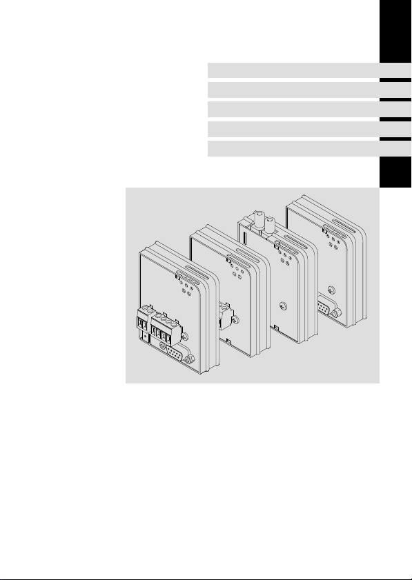
2102LEC001b 2102LEC002b
2102LEC003b 2102LEC004b
0Abb. 0Tab. 0
4
2102LEC007 E82ZBLC001C
EDKMF2102 DE/EN/FR 8.0
Page 5

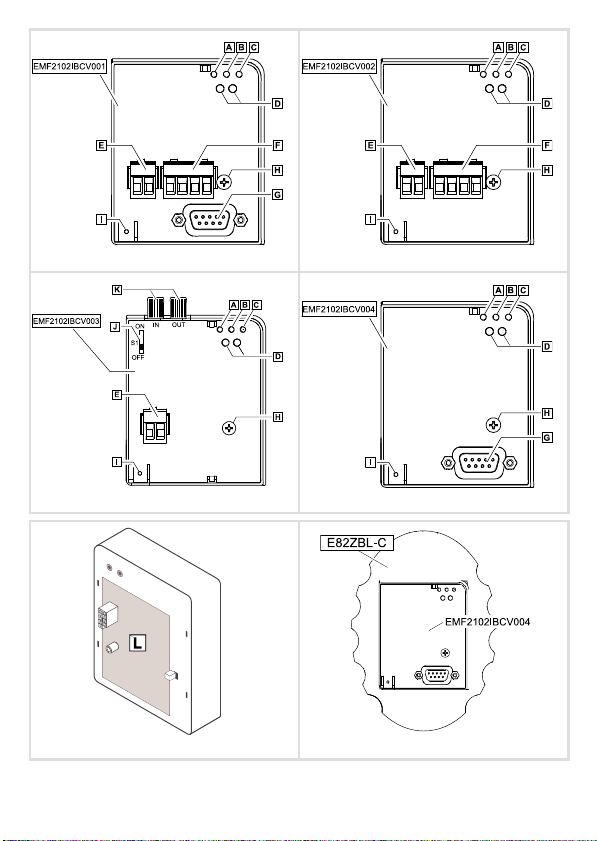
Pos. Beschreibung Ausführliche
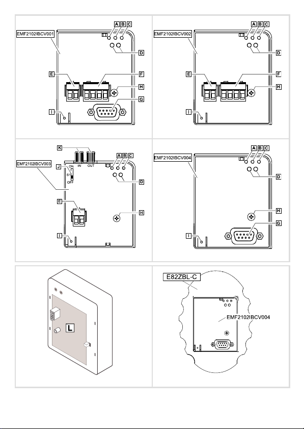
Kommunikationsmodul EMF2102IBC−V001, LECOM−A/B (RS232/RS485)
Kommunikationsmodul EMF2102IBC−V002, LECOM−B (RS485)
Kommunikationsmodul EMF2102IBC−V003, LECOM−LI (Lichtwellenleiter)
Kommunikationsmodul EMF2102IBC−V004, LECOM−A (RS232)
E82ZBL−C: Kommunikationsmodul EMF2102IBC−V004, LECOM−A (RS232), mit
Handterminal
Statusanzeige (grün) Spannungsversorgung
Statusanzeige (gelb) Datenempfang
Statusanzeige (gelb) Datenversand
Statusanzeige (rot/grün) des Antriebsreglers
Steckerleiste, Anschluss für externe Spannungsversorgung
Steckerleiste RS485, Anschluss der RS485−Schnittstelle
Sub−D−Buchse RS232, Anschluss der RS232−Schnittstelle
Befestigungsschraube
PE−Anschluss (nur bei 82XX)
Umschalter Sendeleistung (normal/hoch)
Lichtwellenleiter−Empfänger (schwarz)
Lichtwellenleiter−Sender (weiß)
Typenschild 15
Information
29
43
24
32
28
34
34
EDKMF2102 DE/EN/FR 8.0
5
Page 6

i Inhalt
1 Über diese Dokumentation 7. . . . . . . . . . . . . . . . . . . . . . . . . . . . . . . . . . . . . . . . . .
Verwendete Konventionen 8. . . . . . . . . . . . . . . . . . . . . . . . . . . . . . . . . . . . . . . . . .
Verwendete Hinweise 9. . . . . . . . . . . . . . . . . . . . . . . . . . . . . . . . . . . . . . . . . . . . . . .
2 Sicherheitshinweise 11. . . . . . . . . . . . . . . . . . . . . . . . . . . . . . . . . . . . . . . . . . . . . . . .
3 Produktbeschreibung 12. . . . . . . . . . . . . . . . . . . . . . . . . . . . . . . . . . . . . . . . . . . . . . .
Funktion 12. . . . . . . . . . . . . . . . . . . . . . . . . . . . . . . . . . . . . . . . . . . . . . . . . . . . . . . . . .
Bestimmungsgemäße Verwendung 12. . . . . . . . . . . . . . . . . . . . . . . . . . . . . . . . . .
Lieferumfang 14. . . . . . . . . . . . . . . . . . . . . . . . . . . . . . . . . . . . . . . . . . . . . . . . . . . . . .
Identifikation 15. . . . . . . . . . . . . . . . . . . . . . . . . . . . . . . . . . . . . . . . . . . . . . . . . . . . . .
4 Technische Daten 16. . . . . . . . . . . . . . . . . . . . . . . . . . . . . . . . . . . . . . . . . . . . . . . . . .
Allgemeine Daten und Einsatzbedingungen 16. . . . . . . . . . . . . . . . . . . . . . . . . . .
Schutzisolierung 17. . . . . . . . . . . . . . . . . . . . . . . . . . . . . . . . . . . . . . . . . . . . . . . . . . .
Abmessungen 18. . . . . . . . . . . . . . . . . . . . . . . . . . . . . . . . . . . . . . . . . . . . . . . . . . . . .
5 Mechanische Installation 19. . . . . . . . . . . . . . . . . . . . . . . . . . . . . . . . . . . . . . . . . . . .
6 Elektrische Installation 20. . . . . . . . . . . . . . . . . . . . . . . . . . . . . . . . . . . . . . . . . . . . . .
Verdrahtung mit einem Leitrechner 20. . . . . . . . . . . . . . . . . . . . . . . . . . . . . . . . . . .
EMV−gerechte Verdrahtung 23. . . . . . . . . . . . . . . . . . . . . . . . . . . . . . . . . . . . . . . . . .
Spannungsversorgung 24. . . . . . . . . . . . . . . . . . . . . . . . . . . . . . . . . . . . . . . . . . . . .
Daten der Anschlussklemmen 26. . . . . . . . . . . . . . . . . . . . . . . . . . . . . . . . . . . . . . . .
Verbindungsaufbau über RS232 (LECOM−A) 27. . . . . . . . . . . . . . . . . . . . . . . . . . . . .
EMF2102IBC−V004 mit Handterminal (LECOM−A) 29. . . . . . . . . . . . . . . . . . . . . . . .
Verbindungsaufbau über RS485 (LECOM−B) 31. . . . . . . . . . . . . . . . . . . . . . . . . . . . .
Verbindungsaufbau über Lichtwellenleiter (LECOM−LI) 34. . . . . . . . . . . . . . . . . . . .
7 Inbetriebnahme 36. . . . . . . . . . . . . . . . . . . . . . . . . . . . . . . . . . . . . . . . . . . . . . . . . . .
Vor dem ersten Einschalten 36. . . . . . . . . . . . . . . . . . . . . . . . . . . . . . . . . . . . . . . . . .
Inbetriebnahme mit Grundgeräten der Reihe 8200 37. . . . . . . . . . . . . . . . . . . . . . .
Inbetriebnahme mit Grundgeräten der Reihe 9300 39. . . . . . . . . . . . . . . . . . . . . . .
Inbetriebnahme mit Grundgeräten der Reihe ECS 41. . . . . . . . . . . . . . . . . . . . . . . .
8 Diagnose 43. . . . . . . . . . . . . . . . . . . . . . . . . . . . . . . . . . . . . . . . . . . . . . . . . . . . . . . . .
LED−Statusanzeigen 43. . . . . . . . . . . . . . . . . . . . . . . . . . . . . . . . . . . . . . . . . . . . . . .
6
EDKMF2102 DE/EN/FR 8.0
Page 7

Über diese Dokumentation 1
1 Über diese Dokumentation
Inhalt
Diese Dokumentation enthält ...
ƒ Sicherheitshinweise, die Sie unbedingt beachten müssen;
ƒ Angaben über Versionsstände der zu verwendenden Lenze Grundgeräte;
ƒ Informationen zur mechanischen und elektrischen Installation des
Kommunikationsmoduls;
ƒ Informationen zur Inbetriebnahme und Diagnose.
Informationen zur Gültigkeit
Die Informationen in dieser Dokumentation sind gültig für folgende Geräte:
ƒ Kommunikationsmodule EMF2102IBC−V00X / E82ZBL−C ab Version 3x.3x.
Zielgruppe
Diese Dokumentation richtet sich an Personen, die die Vernetzung und Fernwartung einer
Maschine projektieren, installieren, in Betrieb nehmen und warten.
Tipp!
Informationen und Hilfsmittel rund um die Lenze−Produkte finden Sie im
Download−Bereich unter
www.lenze.com
EDKMF2102 DE/EN/FR 8.0
7
Page 8

1 Über diese Dokumentation
Verwendete Konventionen
Verwendete Konventionen
Diese Dokumentation verwendet folgende Konventionen zur Unterscheidung verschiedener Arten von Information:
Informationsart Auszeichnung Beispiele/Hinweise
Zahlenschreibweise
Dezimaltrennzeichen
Symbole
Seitenverweis
Punkt Es wird generell der Dezimalpunkt
verwendet.
Beispiel: 1234.56
Verweis auf eine andere Seite mit zusätzlichen Informationen
Beispiel: 16 = siehe Seite 16
8
EDKMF2102 DE/EN/FR 8.0
Page 9

Über diese Dokumentation
Verwendete Hinweise
Verwendete Hinweise
Um auf Gefahren und wichtige Informationen hinzuweisen, werden in dieser Dokumentation folgende Piktogramme und Signalwörter verwendet:
Sicherheitshinweise
Aufbau der Sicherheitshinweise:
Gefahr!
(kennzeichnet die Art und die Schwere der Gefahr)
Hinweistext
(beschreibt die Gefahr und gibt Hinweise, wie sie vermieden werden kann)
Piktogramm und Signalwort Bedeutung
Gefahr von Personenschäden durch gefährliche elektrische Spannung
Gefahr!
Gefahr!
Stop!
Hinweis auf eine unmittelbar drohende Gefahr, die den
Tod oder schwere Verletzungen zur Folge haben kann,
wenn nicht die entsprechenden Maßnahmen getroffen
werden.
Gefahr von Personenschäden durch eine allgemeine Gefahrenquelle
Hinweis auf eine unmittelbar drohende Gefahr, die den
Tod oder schwere Verletzungen zur Folge haben kann,
wenn nicht die entsprechenden Maßnahmen getroffen
werden.
Gefahr von Sachschäden
Hinweis auf eine mögliche Gefahr, die Sachschäden zur
Folge haben kann, wenn nicht die entsprechenden Maßnahmen getroffen werden.
1
EDKMF2102 DE/EN/FR 8.0
9
Page 10

1 Über diese Dokumentation
Verwendete Hinweise
Anwendungshinweise
Piktogramm und Signalwort Bedeutung
Hinweis!
Tipp!
Wichtiger Hinweis für die störungsfreie Funktion
Nützlicher Tipp für die einfache Handhabung
Verweis auf andere Dokumentation
10
EDKMF2102 DE/EN/FR 8.0
Page 11

Sicherheitshinweise 2
2 Sicherheitshinweise
Gefahr!
Unsachgemäßer Umgang mit dem Kommunikationsmodul und dem
Grundgerät kann schwere Personenschäden und Sachschäden verursachen.
Beachten Sie die in der Dokumentation zum Grundgerät enthaltenen
Sicherheitshinweise und Restgefahren.
Stop!
Elektrostatische Entladung
Durch elektrostatische Entladung können elektronische Bauteile innerhalb des
Kommunikationsmoduls beschädigt oder zerstört werden.
Mögliche Folgen:
ƒ Das Kommunikationsmodul ist defekt.
ƒ Die Feldbus−Kommunikation ist nicht möglich oder fehlerhaft.
Schutzmaßnahmen
ƒ Befreien Sie sich vor dem Berühren des Moduls von elektrostatischen
Aufladungen.
EDKMF2102 DE/EN/FR 8.0
11
Page 12

3 Produktbeschreibung
Funktion
3 Produktbeschreibung
Funktion
Das Kommunikationsmodul 2102−Vxxx / E82ZBL−C ermöglicht die Kommunikation von
Lenze-Grundgeräten über Kabel(RS232/485−Interface) oder Lichtwellenleiter.
Bestimmungsgemäße Verwendung
Das Kommunikationsmodul EMF2102IBC−Vxxx / E82ZBL−C ...
ƒ ist ein Betriebsmittel zum Einsatz in industriellen Starkstromanlagen;
ƒ ist eine Zubehör−Baugruppe, die mit folgenden Lenze Grundgeräten eingesetzt
werden kann:
Gerätetyp V001 V002 V003 V004 E82ZBL−C
Frequenzumrichter 8200
– 33.820XE.2x.1x
– 33.820XC.2x.1x
– 33.821XE.2x.2x
– 33.821XC.2x.2x
– 33.822XE.1x.1x
– 33.824XE.1x.1x
– 33.824XC.1x.1x
Frequenzumrichter 8200 vector
– E82EVxxxKxBxxxXXVx14
Frequenzumrichter 8200 motec
– E82MVxxxxxBxxxXXVx14
LCU−Motorstarter
– ELCAMxIxxx4SNNPSNN
Servosystem ECS
– ECSxPxxxx4xxxxXX1A60
– ECSxSxxxx4xxxxXX1A60
– ECSxMxxxx4xxxxXX1A60
– ECSxAxxxx4xxxxXX1A23
– ECSxExxxxC4xXXXVA12
1)
Versorgung des Kommunikationsmoduls ausschließlich über eine externe Spannungsquelle
1)
1)
1)
1)
1)
1)
12
EDKMF2102 DE/EN/FR 8.0
Page 13

Bestimmungsgemäße Verwendung
Produktbeschreibung
Drive PLC
– EPL10200 E 1x.20
Servo−Umrichter 9300
– 33.93XXxE.2x.1x
– 33.93XXxC.2x.1x
Frequenzumrichter 9300
– 33.93XXVE.2x.1x
Servo PLC 9300
– 33.93XXEI 2x.0x, 33.93XXET 2x.0x
– 33.93XXCI 2x.0x, 33.93XXCT 2x.0x
1)
Versorgung des Kommunikationsmoduls ausschließlich über eine externe Spannungsquelle
Jede andere Verwendung gilt als sachwidrig!
3
E82ZBL−CV004V003V002V001Gerätetyp
EDKMF2102 DE/EN/FR 8.0
13
Page 14
3 Produktbeschreibung
Lieferumfang
Lieferumfang
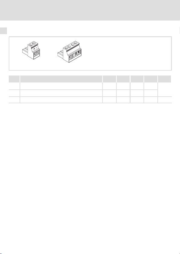
Pos. Kommunikationsmodul EMF2102IBC V001 V002 V003 V004 siehe
Steckerleiste mit Schraubanschluss, 2−polig
Steckerleiste mit Schraubanschluss, 4−polig
Montageanleitung
Zubehör (nicht im Lieferumfang enthalten)
ƒ PC−Systemkabel EWL00xx
ƒ Verbindungsleitung E82ZWLxxx
ƒ Parametriersoftware "Global Drive Control (GDC)", ab Version 3.2
89
88
72
71
2102LEC008, E82ZAFX025, 026, 8200VEC063
l l l
l l
l l l l
Tipp!
Weiterführende Informationen zu diesem Kommunikationsmodul finden Sie
im entsprechenden Kommunikationshandbuch.
Die PDF−Datei finden Sie im Download−Bereich unter
http://www.Lenze.com
26
14
EDKMF2102 DE/EN/FR 8.0
Page 15

Identifikation
L
Type
Id.-No.
Prod.-No.
Ser.-No.
Produktbeschreibung
Identifikation
3
E82AF000P0B201XX
Gerätereihe LECOM
Hardwarestand
Softwarestand
Variante
001: RS485/232−Schnittstelle
002: RS485−Schnittstelle
003: LWL−Schnittstelle
004: RS232−Schnittstelle
EDKMF2102 DE/EN/FR 8.0
33.2102IBC 3x 3x V00x
99371BC013
15
Page 16

4 Technische Daten
Allgemeine Daten und Einsatzbedingungen
4 Technische Daten
Allgemeine Daten und Einsatzbedingungen
Bereich
Kommunikations−
medien
Strombedarf 80 mA 60 mA 70 mA −
Protokoll LECOM−A/B V2.0
Übertragungszei-
chenformat
Übertragungsrate
[Bits/s]
Schutzart IP20
Umgebungstempera-
tur
Klimatische
Bedingungen
Externe DC−Spannungsversorgung (Steckerleiste 24V DC)
= 15 bis 30 V DC; w = 5%
U
eff
= 20 bis 25 V DC; w = 48%; Uss < 35 V
U
eff
Kommunikationsmodul EMF2102IBC
−V001 −V002 −V003 −V004 /
RS232 (LECOM−A)
RS485 (LECOM−B)
7 Bit ASCII; 1 Stoppbit; 1 Startbit; 1 Paritätsbit (gerade)
1200, 2400, 4800, 9600, 19200
im Betrieb: 0°C ... +55 °C
Transport: − 25°C ... +70 °C
Lagerung:
Klasse 3K3 nach EN 50178
(ohne Betauung, mittlere relative Feuchte 85 %)
RS485 (LECOM−B) LWL (LECOM−LI) RS232 (LECOM−A)
− 25°C ... +60 °C
E82ZBL−C
16
EDKMF2102 DE/EN/FR 8.0
Page 17

Technische Daten
Schutzisolierung
Schutzisolierung
Schutzisolierung zwischen
Bus und ...
Bezugserde / PE Betriebsisolierung nicht
externer Versorgung Betriebsisolierung verstärkte
Leistungsteil
820X / 821X Basisisolierung
822X / 8200 vector
93XX / 9300 Servo PLC
Servosystem ECS
Steuerklemmen
820X / 8200 vector
821X
822X
Drive PLC
93XX / 9300 Servo PLC
Servosystem ECS verstärkte Isolierung verstärkte Isolierung
Art der Isolierung für Kommunikationsmodule EMF2102IBC
−V001 −V002 −V003 −V004 / E82ZBL−C
erforderlich
Isolierung
verstärkte
verstärkte Isolierung verstärkte Isolierung
Betriebsisolierung verstärkte
Basisisolierung Basisisolierung
Isolierung
Isolierung
Betriebsisolierung
−
Basisisolierung
Betriebsisolierung
4
EDKMF2102 DE/EN/FR 8.0
17
Page 18
4 Technische Daten
+
_
Abmessungen
Abmessungen
IN
ON
OUT
S1
84
OFF
75
b1
24V DC
+
b
L
A/B/LI
LECOM
RS485
_
88
89
72
71
RS232
2102
61
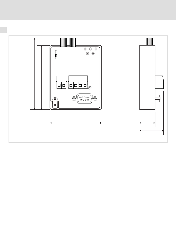
a
a61 mm
b 83 mm (nur EMF2102IBC−V003, LECOM−LI)
b1 75 mm
e 28 mm
e1 18 mm
18
e1
28
e
2102LEC013
18
EDKMF2102 DE/EN/FR 8.0
Page 19
Mechanische Installation 5
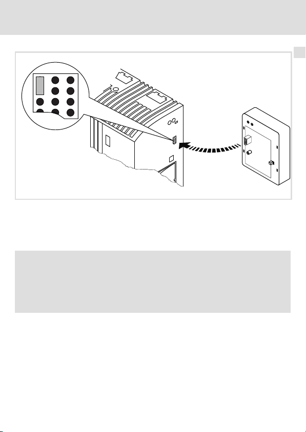
5 Mechanische Installation
2102LEC014
Abb. 1 Kommunikationsmodul aufstecken
ƒ Stecken Sie das Kommunikationsmodul auf das Grundgerät (hier: 8200 vector).
ƒ Schrauben Sie das Kommunikationsmodul mit der Befestigungsschraube auf dem
Grundgerät fest, um eine gute PE−Verbindung sicher zu stellen.
Hinweis!
Zur internen Versorgung des Kommunikationsmoduls durch den
Frequenzumrichter 8200 vector muss der Jumper in der Schnittstellenöffnung
(siehe Abb. oben) angepasst werden.
Beachten Sie die Hinweise (25).
EDKMF2102 DE/EN/FR 8.0
19
Page 20

6 Elektrische Installation
Verdrahtung mit einem Leitrechner
6 Elektrische Installation
Verdrahtung mit einem Leitrechner
Gefahr!
Sie müssen eine zusätzliche Potenzialtrennung installieren, wenn ...
ƒ ein Antriebsregler 820X und 821X mit einem Leitrechner verbunden wird
und
ƒ eine sichere Potenzialtrennung (verstärkte Isolierung) nach EN 61800−5−1
notwendig ist.
Allgemeine Angaben zur Verdrahtung:
1. Bustopologie einhalten, deshalb keine Stichleitungen verwenden.
2. LECOM−Kabel entsprechend der Kabelspezifikation verwenden.
20
EDKMF2102 DE/EN/FR 8.0
Page 21

Elektrische Installation
Verdrahtung mit einem Leitrechner
Spezifikation des Übertragungskabels
Hinweis!
Verwenden Sie ausschließlich Kabel, die den aufgeführten Spezifikationen
entsprechen.
6
Spezifikation Übertragungskabel für RS232
Kabeltyp LIYCY 4 x 0.25 mm
Leitungswiderstand
Kapazitätsbelag < 140 nF/km
Spezifikation Übertragungskabel für RS485
l Gesamtleitungslänge bis 300 m:
Kabeltyp
Leitungswiderstand 40 /km
Kapazitätsbelag 130 nF/km
l Gesamtleitungslänge bis 1200 m:
Kabeltyp CYPIMF 1 x 2 x 0.5 mm2 abgeschirmt
Leitungswiderstand 40 /km
Kapazitätsbelag 130 nF/km
EDKMF2102 DE/EN/FR 8.0
< 100 /km
LIYCY 1 x 2 x 0.5 mm2 abgeschirmt
2
, abgeschirmt
21
Page 22

6 Elektrische Installation
Verdrahtung mit einem Leitrechner
Spezifikation Lichtwellenleiter−Kabel
Minimaler Biegeradius 30 mm
Maximale Zugkraft 100 N
Spannungsfestigkeit 110 kV/m
Arbeitstemperatur
Wellenlänge 660 nm
Dämpfung 100 dB/km ... 400 dB/km
Leitungslänge zwischen zwei Teilneh-
mern
(Kabeldämpfung = 150 dB/km)
Faserkernmaterial/Durchmesser Polymethylmethacrylat (PMMA) / 976 m
Fasermantelmaterial/Durchmesser Flurorpolymer / 1000 m
Außenmantelmaterial/Durchmesser Thermoplastischer Polyester (PE) / 2.2 mm
*40°C ... )80 C
l 0 bis 40 m (normale Sendeleistung)
l 10 bis 66 m (hohe Sendeleistung)
22
EDKMF2102 DE/EN/FR 8.0
Page 23

Elektrische Installation
EMV−gerechte Verdrahtung
EMV−gerechte Verdrahtung
Für eine EMV−gerechte Verdrahtung beachten Sie folgende Punkte:
Hinweis!
ƒ Steuer−/Datenleitungen getrennt von Motorleitungen verlegen.
ƒ Legen Sie die Schirme der Steuer−/Datenleitungen bei digitalen Signalen
beidseitig auf.
ƒ Zur Vermeidung von Potenzialdifferenzen zwischen den
Kommunikationsteilnehmern eine Ausgleichsleitung mit einem
Querschnitt von mindestens 16mm
ƒ Beachten Sie die weiteren Hinweise zur EMV−gerechten Verdrahtung in der
Dokumentation des Grundgerätes.
2
einsetzen (Bezug:PE).
6
EDKMF2102 DE/EN/FR 8.0
23
Page 24

6 Elektrische Installation
Spannungsversorgung
Spannungsversorgung
Externe Spannungsversorgung
Hinweis!
Verwenden Sie bei externer Spannungsversorgung und bei größeren
Entfernungen zwischen den Schaltschränken in jedem Schaltschrank immer
ein separates und nach EN 61800−5−1 sicher getrenntes Netzteil (SELV/PELV).
ƒ Die externe Spannungsversorgung des Kommunikationsmoduls ist notwendig, wenn
beim Ausfall der Versorgung des Grundgerätes die Kommunikation bestehen bleiben
soll.
ƒ Der Zugriff auf Parameter eines vom Netz getrennten Grundgerätes ist nicht
möglich.
ƒ Die externe Spannungsversorgung erfolgt über die 2−polige Steckerleiste.
Bezeichnung Beschreibung
+ Externe Spannungsversorgung
− Bezugspotenzial für externe Spannungsversorgung
U = 24VDC±10%
24
EDKMF2102 DE/EN/FR 8.0
Page 25
Elektrische Installation
Spannungsversorgung
Interne Spannungsversorgung
Hinweis!
Die Vorgabe der internen Spannungsversorgung ist bei Grundgeräten mit
erweiterter AIF−Schnittstellenöffnung (z. B. Frontseite 8200 vector) gegeben.
Die in der Grafik grau hervorgehobene Fläche kennzeichnet die
Jumper−Position.
ƒ Im Auslieferungszustand des Grundgerätes werden diese nicht intern
versorgt.
ƒ Zur internen Spannungsversorgung platzieren Sie den Jumper auf die
unten angegebene Position.
Bei allen anderen Gerätereihen (9300, ECS) ist eine Spannungsversorgung vom
Grundgerät immer vorhanden.
(Nur externe Spannungsversorgung möglich.)
Auslieferungszustand
Interne Spannungsversorgung
6
EDKMF2102 DE/EN/FR 8.0
25
Page 26
6 Elektrische Installation
Daten der Anschlussklemmen
Daten der Anschlussklemmen
Bereich Werte
Elektrischer Anschluss Steckerleiste mit Schraubanschluss
Anschlussmöglichkeiten
Anzugsmoment 0.5 ... 0.6 Nm (4.4 ... 5.3 lb−in)
Abisolierlänge 6 mm
starr:
flexibel:
1.5 mm
ohne Aderendhülse
1.5 mm
mit Aderendhülse, ohne Kunststoffhülse
1.5 mm
mit Aderendhülse, mit Kunststoffhülse
1.5 mm
2
(AWG 16)
2
(AWG 16)
2
(AWG 16)
2
(AWG 16)
26
EDKMF2102 DE/EN/FR 8.0
Page 27
Verbindungsaufbau über RS232 (LECOM−A)
Elektrische Installation
Verbindungsaufbau über RS232 (LECOM−A)
Hinweis!
Verwenden Sie ein vorkonfektioniertes PC−Systemkabel (EWL00xx).
6
2102LEC009
EDKMF2102 DE/EN/FR 8.0
27
Page 28
6 Elektrische Installation
Verbindungsaufbau über RS232 (LECOM−A)
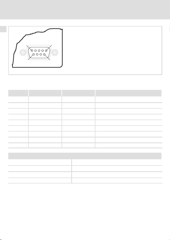
RS232
5
1
9
RS232−Schnittstelle für Kommunikationsmodul EMF2102IBC−V001 / −V004 (Sub−D−
Buchse, 9−polig)
Pin Bezeichnung Ein−/Ausgang Belegung
1− − unbenutzt
2 RxD Eingang Datenempfangsleitung RS232
3 TxD Ausgang Datensendeleitung RS232
4 DTR Ausgang Sendesteuerung
5 GND − Bezugspotential
6 DSR Eingang unbenutzt RS232
7 T/R(A) Ein−/Ausgang RS485 (nur 2102−V001)
8 T/R(B) Ein−/Ausgang RS485 (nur 2102−V001)
9 Vcc5 Ausgang Versorgung +5V / 10 mA
Eigenschaften der Verdrahtung für RS232
Kommunikationsmedien RS232 (LECOM−A)
Netzwerk−Topologie Punkt−zu−Punkt
Mögliche Anzahl der Antriebsregler 1
Maximale Leitungslänge 15 m
6
2102
2102LEC015
28
EDKMF2102 DE/EN/FR 8.0
Page 29
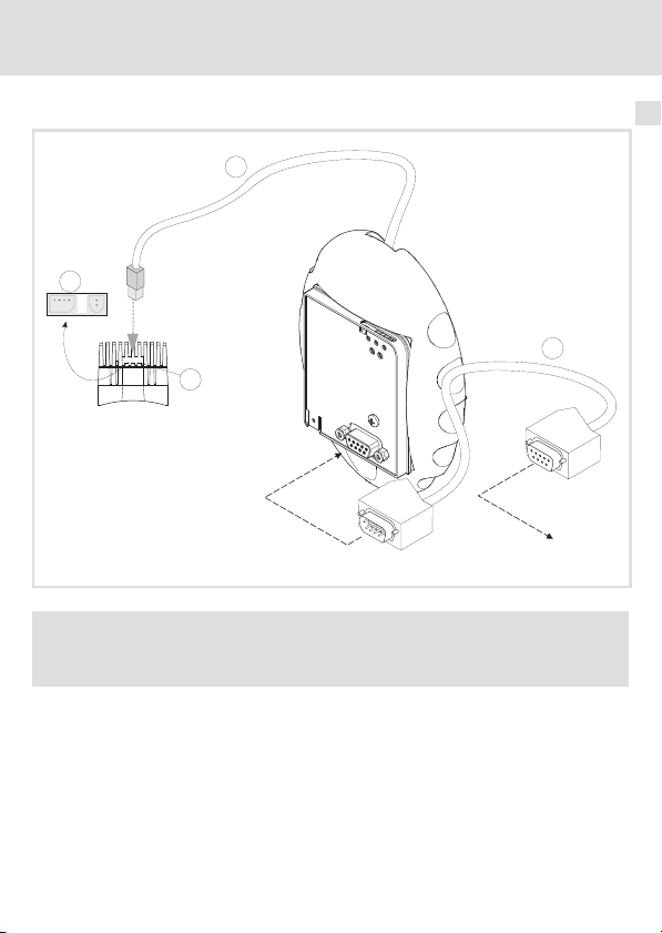
EMF2102IBC−V004 mit Handterminal (LECOM−A)
C
EMF2102IBC−V004 mit Handterminal (LECOM−A)
2
E82ZWLxxx
3
Elektrische Installation
AIF
8200 motec
Hinweis!
Verwenden Sie ein vorkonfektioniertes PC−Systemkabel (EWL00xx).
1
EWL00xx
P
2102LEC016
6
EDKMF2102 DE/EN/FR 8.0
29
Page 30

6 Elektrische Installation
EMF2102IBC−V004 mit Handterminal (LECOM−A)
So verdrahten Sie die Komponenten:
1. Kommunikationsmodul über PC−Systemkabel mit dem PC verbinden.
2. Verbindungsleitung in das Handterminal einstecken.
3. Verschlussstopfen am Kühlkörper entfernen.
4. Verbindungsleitung in die AIF−Schnittstelle des Antriebsreglers einstecken.
5. Bei eingeschalteter Netzspannung ist das Kommunikationsmodul jetzt
betriebsbereit.
Für die Inbetriebnahme können Sie jetzt mit dem Antriebsregler kommunizieren, d. h. alle
Codestellen lesen und die beschreibbaren Codestellen verändern.
Hinweis!
Das Einstecken oder Entfernen des Kommunikationsmoduls und das
Parametrieren ist während des Betriebs möglich.
30
EDKMF2102 DE/EN/FR 8.0
Page 31

Verbindungsaufbau über RS485 (LECOM−B)
Verbindungsaufbau über RS485 (LECOM−B)
Elektrische Installation
2102LEC010
6
Hinweis!
Verwenden Sie bitte für die Verdrahtung des RS485−Schnittstellenkabels nur
abgeschirmtes und paarig verseiltes Kabel !
EDKMF2102 DE/EN/FR 8.0
31
Page 32
6 Elektrische Installation
Verbindungsaufbau über RS485 (LECOM−B)
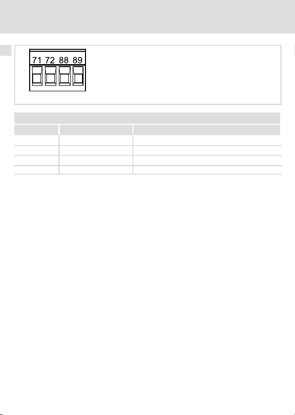
RS485−Schnittstelle über Steckerleiste, 4−polig
Klemme Bezeichnung Belegung
71 T/R(B) RS485
72 T/R(A) RS485
88 S−C Kapazitive Schirmung nach PE
89 S Direkte Schirmung nach PE
2102LEC018
32
EDKMF2102 DE/EN/FR 8.0
Page 33

Elektrische Installation
+
_
+
_
6
Verbindungsaufbau über RS485 (LECOM−B)
IPC/SPS
T/R(B)
T/R(A)
L
A/
LECOM B A/
24V DC
RS485
88
89
72
71
RS232
PE
2102
24V DC
71
L
RS485
88
72
RS232
LECOM B
89
2102
2102LEC011
Verbindung zwischen zwei Antriebsreglern
ƒ Den Kabelschirm auf Klemme 89 (direkt PE) des einen Kommunikationsmoduls und
auf Klemme 88 (kapazitiv PE) des anderen Kommunikationsmoduls legen. Dadurch
werden Potenzialausgleichsströme über den Kabelschirm vermieden.
ƒ Die Klemmen 71 und 72 zwischen den Kommunikationsmodulen über ein
miteinander verseiltes Adernpaar (z. B. grün und gelb) verbinden.
Direkte Verbindung zum Leitrechner
ƒ Den Kabelschirm am Leitrechner auf PE und am Antriebsregler auf Klemme 88 legen.
Dadurch werden Potenzialausgleichsströme über den Kabelschirm vermieden.
EDKMF2102 DE/EN/FR 8.0
33
Page 34

6 Elektrische Installation
Verbindungsaufbau über Lichtwellenleiter (LECOM−LI)
Verbindungsaufbau über Lichtwellenleiter (LECOM−LI)
Eigenschaften der Verdrahtung für Lichtwellenleiter
Kommunikationsmedien Lichtwellenleiter (Kunststoff)
Netzwerk−Topologie Ring
Mögliche Anzahl der Antriebsregler 52
Maximale Leitungslänge
l 0 bis 40 m bei normaler Sendeleistung (S1 = OFF)
l 10 bis 66 m bei hoher Sendeleistung (S1 = ON)
2102LEC012
34
EDKMF2102 DE/EN/FR 8.0
Page 35

Verbindungsaufbau über Lichtwellenleiter (LECOM−LI)
Lichtwellenleiter−Kabel (LWL−Kabel) zur Verdrahtung vorbereiten
LWL−Kabel konfektionieren
Die LWL−Kabel können ohne Spezialwerkzeug konfektioniert werden.
1. LWL−Kabel auf eine harte Unterlage legen und z. B. mit einem Messer auf die
gewünschte Länge zuschneiden.
2. Bei LWL−Kabeln mit PUR−Mantel (rot) ca. 20 mm abisolieren (das Abisolieren von
PE−Material ist nicht erforderlich).
Hinweis!
Elektrische Installation
Bei unpolierten LWL−Enden vermindert sich die max. LWL−Länge um typisch
20 %. Polieren Sie deshalb das Ende des LWL−Kabels (Körnung: P1000).
LWL−Kabel montieren
1. LWL−Quetschverschraubung des Steckers lösen.
2. Ende des LWL−Kabels bis zum Anschlag in den LWL−Anschluss einstecken.
3. LWL−Quetschverschraubung festdrehen.
LWL−Ring aufbauen
Hinweis!
Biegeradius von 30 mm nicht unterschreiten, sonst vermindert sich die
maximale LWL−Kabellänge um typisch 50 % je Bogen.
1. Weißen LWL−Anschluss (Sender, TxD) am Leitrechner mit schwarzem LWL−Anschluss
(Empfänger, RxD) am nächsten Antriebsregler verbinden.
2. Weißen LWL−Anschluss am Antriebsregler mit schwarzem LWL−Anschluss am
nächsten Antriebsregler verbinden.
3. Weißen LWL−Anschluss am letzten Antriebsregler mit schwarzem LWL−Anschluss am
Leitrechner verbinden.
4. Stellen Sie eine hohe Sendeleistung ein, falls die LWL−Kabellänge zwischen zwei
Antriebsreglern größer als 40 m ist. Dazu Schalter S1 auf ON stellen. Die maximale
Kabellänge erhöht sich dadurch auf 66 m (bei einer Kabeldämpfung von 150 dB/km).
6
EDKMF2102 DE/EN/FR 8.0
35
Page 36

7 Inbetriebnahme
Vor dem ersten Einschalten
7 Inbetriebnahme
Vor dem ersten Einschalten
Stop!
Bevor Sie das Grundgerät mit dem Kommunikationsmodul erstmalig
einschalten, überprüfen Sie ...
ƒ die gesamte Verdrahtung auf Vollständigkeit, Kurzschluss und Erdschluss;
ƒ bei Verwendung des Kommunikationsmoduls EMF2102IBC−V003
(LECOM−LI) die Stellung des Umschalters für die erforderliche
Sendeleistung (34).
36
EDKMF2102 DE/EN/FR 8.0
Page 37

Inbetriebnahme mit Grundgeräten der Reihe 8200
Inbetriebnahme
Inbetriebnahme mit Grundgeräten der Reihe 8200
Schritt Vorgehensweise Ausführliche
1.
Netzspannung zuschalten und ggf. externe Spannungsversorgung
des Kommunikationsmoduls zuschalten.
l Das Grundgerät ist nach ca. 1 Sekunde betriebsbereit.
Reaktion
l Die grüne LED, Spannungsversorgung, auf der Frontseite des
Kommunikationsmoduls muss leuchten.
l Die Statusanzeige des Antriebsreglers muss leuchten oder blin-
ken.
Hinweis zu Schritt 2. und Schritt 3.
Beachten Sie, dass der Leitrechner zur Vorgabe der Übertragungsrate und der Geräteadresse umparametriert werden muss. Ohne Anpassung erkennt der Leitrechner bei Veränderung der Übertragungsrate (C0125) die Antwort nicht, da diese schon mit der neuen Übertragungsrate vom Antriebsregler
gesendet wird.
2.
Übertragungsrate einstellen.
l Mit Codestelle C0125 die Übertragungsrate (LECOM−Baudrate)
einstellen.
l Die Übertragungsrate muss für jeden Busteilnehmer identisch
eingestellt werden.
l Der Wert kann z. B. über das Keypad XT vorgegeben werden.
l Änderungen dieser Codestelle werden sofort wirksam.
Lenze−Einstellung: 9600 kBit/s
3.
Geräteadresse zuweisen.
l Jedem Busteilnehmer mit Codestelle C0009 eine im Netzwerk
eindeutige Geräteadresse zuweisen. Nur so kann der Leitrechner
einen bestimmten Antriebsregler auch eindeutig erreichen.
l Die Werte 00, 10, 20, 30,, 90 dürfen nicht eingestellt werden,
da diese für Gruppen−Adressierungen reserviert sind.
l Der Wert kann z. B. über das Keypad XT vorgegeben werden.
l Änderungen dieser Codestelle werden sofort wirksam.
Lenze−Einstellung: 1
Information
43
Dokumentation
Antriebsregler
7
EDKMF2102 DE/EN/FR 8.0
37
Page 38

7 Inbetriebnahme
Inbetriebnahme mit Grundgeräten der Reihe 8200
VorgehensweiseSchritt
Nun können Sie mit jedem Antriebsregler kommunizieren, d. h. Sie können alle Codestellen lesen
und alle beschreibbaren Codestellen verändern.
4.
Weitere erforderliche Einstellungen am Antriebsregler vornehmen.
Inbetriebnahme des Antriebsreglers
l Den Frequenz−Sollwert mit C0046 und das Steuerwort mit C0135
vorgeben.
l Die Bedienungsart C0001= 3 einstellen.
l Mit Drehzahlsollwert = 0 ist beim Einschalten in dieser Bedie-
nungsart Schnellhalt (QSP) aktiv. Dadurch wird ein unkontrollierter Anlauf des Antriebsreglers verhindert.
– Aufheben der QSP−Funktion: C0135/Bit 3 = 0 (FALSE) setzen.
Ausführliche
Information
Dokumentation
Antriebsregler
38
EDKMF2102 DE/EN/FR 8.0
Page 39

Inbetriebnahme mit Grundgeräten der Reihe 9300
Inbetriebnahme
Inbetriebnahme mit Grundgeräten der Reihe 9300
Schritt Vorgehensweise Ausführliche
1.
Netzspannung zuschalten und ggf. externe Spannungsversorgung
des Kommunikationsmoduls zuschalten.
l Das Grundgerät ist nach ca. 1 Sekunde betriebsbereit.
Reaktion
l Die grüne LED, Spannungsversorgung, auf der Frontseite des
Kommunikationsmoduls muss leuchten.
l Die Statusanzeige des Antriebsreglers muss leuchten oder blin-
ken.
Hinweis zu Schritt 2. und Schritt 3.
Beachten Sie, dass der Leitrechner zur Vorgabe der Übertragungsrate und der Geräteadresse umparametriert werden muss. Ohne Anpassung erkennt der Leitrechner bei Veränderung der Übertragungsrate (C0125) die Antwort nicht, da diese schon mit der neuen Übertragungsrate vom Antriebsregler
gesendet wird.
2.
Übertragungsrate einstellen.
l Mit Codestelle C0125 die Übertragungsrate (LECOM−Baudrate)
einstellen.
l Die Übertragungsrate muss für jeden Busteilnehmer identisch
eingestellt werden.
l Der Wert kann z. B. über das Keypad XT vorgegeben werden.
l Änderungen dieser Codestelle werden sofort wirksam.
Lenze−Einstellung: 9600 kBit/s
3.
Geräteadresse zuweisen.
l Jedem Busteilnehmer mit Codestelle C0009 eine im Netzwerk
eindeutige Geräteadresse zuweisen. Nur so kann der Leitrechner
einen bestimmten Antriebsregler auch eindeutig erreichen.
l Die Werte 00, 10, 20, 30,, 90 dürfen nicht eingestellt werden,
da diese für Gruppen−Adressierungen reserviert sind.
l Der Wert kann z. B. über das Keypad XT vorgegeben werden.
l Änderungen dieser Codestelle werden sofort wirksam.
Lenze−Einstellung: 1
Nun können Sie mit jedem Antriebsregler kommunizieren, d. h. Sie können alle Codestellen lesen
und alle beschreibbaren Codestellen verändern.
Information
43
Dokumentation
Antriebsregler
7
EDKMF2102 DE/EN/FR 8.0
39
Page 40

7 Inbetriebnahme
Inbetriebnahme mit Grundgeräten der Reihe 9300
4.
VorgehensweiseSchritt
Weitere erforderliche Einstellungen am Antriebsregler vornehmen.
Inbetriebnahme des Antriebsreglers
l Für die Erst−Inbetriebnahme die Codestelle C0005 = 1011 einstel-
len (Signalkonfiguration: Drehzahlregelung über AIF).
l Antriebsregler freigeben.
– Die Klemme 28 (RFR: Reglerfreigabe) ist immer aktiv und
muss während des Betriebs auf HIGH−Pegel liegen. Andernfalls
ist der Antriebsregler gesperrt.
l Den Drehzahlsollwert mit C0141 in % von n
vorgeben.
Hinweis
Bei der Signalkonfiguration C0005=xx11 ist die Klemme A1 als Spannungsausgang geschaltet. Verdrahten Sie somit nur folgende Klemmen miteinander:
l X5.A1 mit X5.28 (RFR)
l X5.A1 mit X5.E1 (Rechtslauf / QSP)
(Wert in C0011)
max
Ausführliche
Information
Dokumentation
Antriebsregler
40
EDKMF2102 DE/EN/FR 8.0
Page 41

Inbetriebnahme mit Grundgeräten der Reihe ECS
Inbetriebnahme
Inbetriebnahme mit Grundgeräten der Reihe ECS
Schritt Vorgehensweise Ausführliche
1.
Netzspannung zuschalten und ggf. externe Spannungsversorgung
des Kommunikationsmoduls zuschalten.
l Das Grundgerät ist nach ca. 1 Sekunde betriebsbereit.
Reaktion
l Die grüne LED, Spannungsversorgung, auf der Frontseite des
Kommunikationsmoduls muss leuchten.
l Die Statusanzeige des Antriebsreglers muss leuchten oder blin-
ken.
Hinweis zu Schritt 2. und Schritt 3.
Beachten Sie, dass der Leitrechner zur Vorgabe der Übertragungsrate und der Geräteadresse umparametriert werden muss. Ohne Anpassung erkennt der Leitrechner bei Veränderung der Übertragungsrate (C0125) die Antwort nicht, da diese schon mit der neuen Übertragungsrate vom Antriebsregler
gesendet wird.
2.
Übertragungsrate einstellen.
l Mit Codestelle C0125 die Übertragungsrate (LECOM−Baudrate)
einstellen.
l Die Übertragungsrate muss für jeden Busteilnehmer identisch
eingestellt werden.
l Der Wert kann z. B. über das Keypad XT vorgegeben werden.
l Änderungen dieser Codestelle werden sofort wirksam.
Lenze−Einstellung: 9600 kBit/s
3.
Geräteadresse zuweisen.
l Jedem Busteilnehmer mit Codestelle C0009 eine im Netzwerk
eindeutige Geräteadresse zuweisen. Nur so kann der Leitrechner
einen bestimmten Antriebsregler auch eindeutig erreichen.
l Die Werte 00, 10, 20, 30,, 90 dürfen nicht eingestellt werden,
da diese für Gruppen−Adressierungen reserviert sind.
l Der Wert kann z. B. über das Keypad XT vorgegeben werden.
l Änderungen dieser Codestelle werden sofort wirksam.
Lenze−Einstellung: 1
Nun können Sie mit jedem Antriebsregler kommunizieren, d. h. Sie können alle Codestellen lesen
und alle beschreibbaren Codestellen verändern.
Information
43
Dokumentation
Antriebsregler
7
EDKMF2102 DE/EN/FR 8.0
41
Page 42

7 Inbetriebnahme
Inbetriebnahme mit Grundgeräten der Reihe ECS
4.
VorgehensweiseSchritt
Weitere erforderliche Einstellungen am Antriebsregler vornehmen.
Inbetriebnahme des Antriebsreglers
l Für die Erst−Inbetriebnahme die Codestelle C0005 = 1003 einstel-
len (Signalkonfiguration: Drehzahlregelung über AIF).
l Antriebsregler freigeben.
– Die Klemmen SI1 (Reglerfreigabe) und SI2 (Impulssperre) sind
immer aktiv und müssen während des Betriebs auf HIGH−
Pegel liegen. Andernfalls ist der Antriebsregler gesperrt.
Hinweis
Der Antriebsregler muss immer extern mit 24 V DC versorgt werden.
Ausführliche
Information
Dokumentation
Antriebsregler
42
EDKMF2102 DE/EN/FR 8.0
Page 43

8 Diagnose
LED−Statusanzeigen
Pos. Farbe Zustand Beschreibung
grün
an Das Kommunikationsmodul ist mit Spannung versorgt und hat eine
aus Das Kommunikationsmodul ist nicht mit Spannung versorgt. Der An-
blinkt Das Kommunikationsmodul ist mit Spannung versorgt, hat aber (noch)
gelb blinkt Der Antriebsregler empfängt ein Telegramm.
gelb blinkt Der Antriebsregler sendet ein Telegramm.
rot /
an /
grün
blinkt
Verbindung zum Antriebsregler.
triebsregler oder die externe Spannungsversorgung ist ausgeschaltet.
keine Verbindung zum Antriebsregler, weil ...
l das Kommunikationsmodul nicht korrekt auf den Antriebsregler
gesteckt wurde;
l der Datentransfer vom/zum Antriebsregler noch nicht möglich ist
(z. B. Antriebsregler in der Initialisierungsphase).
Die Rote und grüne Drive−LED kennzeichnet den Betriebszustand des
Grundgerätes 82XX, 8200 vector, 93XX, Servo PLC 9300 und Drive PLC
(siehe Betriebsanleitung des Grundgerätes).
Diagnose
LED−Statusanzeigen
8
EDKMF2102 DE/EN/FR 8.0
43
Page 44
2102LEC001b 2102LEC002b
2102LEC003b 2102LEC004b
0Fig. 0Tab. 0
44
2102LEC007 E82ZBLC001C
EDKMF2102 DE/EN/FR 8.0
Page 45

Pos. Description Detailed
Communication module EMF2102IBC−V001, LECOM−A/B (RS232/RS485)
Communication module EMF2102IBC−V002, LECOM−B (RS485)
Communication module EMF2102IBC−V003, LECOM−LI (optical fibre)
Communication module EMF2102IBC−V004, LECOM−A (RS232)
E82ZBL−C: communication module EMF2102IBC−V004, LECOM−A (RS232),
with diagnosis terminal
Status indicator (green) voltage supply
Status indicator (yellow) data reception
Status indicator (yellow) data transmission
Status indicator (red/green) of the controller
Plug connector, connection for external voltage supply
RS485 plug connector, RS485 interface connection
RS232 Sub−D socket, RS232 interface connection
Fixing screw
PE connection (only with 82XX)
Output power selector (normal/high)
Optical fibre receiver (black)
Optical fibre transmitter (white)
Nameplate 55
information
68
82
63
71
67
73
73
EDKMF2102 DE/EN/FR 8.0
45
Page 46

i Contents
1 About this documentation 47. . . . . . . . . . . . . . . . . . . . . . . . . . . . . . . . . . . . . . . . . . .
Conventions used 48. . . . . . . . . . . . . . . . . . . . . . . . . . . . . . . . . . . . . . . . . . . . . . . . . .
Notes used 49. . . . . . . . . . . . . . . . . . . . . . . . . . . . . . . . . . . . . . . . . . . . . . . . . . . . . . . .
2 Safety instructions 51. . . . . . . . . . . . . . . . . . . . . . . . . . . . . . . . . . . . . . . . . . . . . . . . .
3 Product description 52. . . . . . . . . . . . . . . . . . . . . . . . . . . . . . . . . . . . . . . . . . . . . . . . .
Function 52. . . . . . . . . . . . . . . . . . . . . . . . . . . . . . . . . . . . . . . . . . . . . . . . . . . . . . . . .
Application as directed 52. . . . . . . . . . . . . . . . . . . . . . . . . . . . . . . . . . . . . . . . . . . . .
Scope of supply 54. . . . . . . . . . . . . . . . . . . . . . . . . . . . . . . . . . . . . . . . . . . . . . . . . . . .
Identification 55. . . . . . . . . . . . . . . . . . . . . . . . . . . . . . . . . . . . . . . . . . . . . . . . . . . . . .
4 Technical data 56. . . . . . . . . . . . . . . . . . . . . . . . . . . . . . . . . . . . . . . . . . . . . . . . . . . . .
General data and operating conditions 56. . . . . . . . . . . . . . . . . . . . . . . . . . . . . . .
Protective insulation 57. . . . . . . . . . . . . . . . . . . . . . . . . . . . . . . . . . . . . . . . . . . . . . . .
Dimensions 58. . . . . . . . . . . . . . . . . . . . . . . . . . . . . . . . . . . . . . . . . . . . . . . . . . . . . . .
5 Mechanical installation 59. . . . . . . . . . . . . . . . . . . . . . . . . . . . . . . . . . . . . . . . . . . . .
6 Electrical installation 60. . . . . . . . . . . . . . . . . . . . . . . . . . . . . . . . . . . . . . . . . . . . . . .
Wiring to a host 60. . . . . . . . . . . . . . . . . . . . . . . . . . . . . . . . . . . . . . . . . . . . . . . . . . . .
EMC−compliant wiring 62. . . . . . . . . . . . . . . . . . . . . . . . . . . . . . . . . . . . . . . . . . . . . .
Voltage supply 63. . . . . . . . . . . . . . . . . . . . . . . . . . . . . . . . . . . . . . . . . . . . . . . . . . . .
Connection terminals 65. . . . . . . . . . . . . . . . . . . . . . . . . . . . . . . . . . . . . . . . . . . . . .
Connection established via RS232 (LECOM−A) 66. . . . . . . . . . . . . . . . . . . . . . . . . . .
EMF2102IBC−V004 with diagnosis terminal (LECOM−A) 68. . . . . . . . . . . . . . . . . . .
Connection established via RS485 (LECOM−B) 70. . . . . . . . . . . . . . . . . . . . . . . . . . .
Connection established via optical fibre (LECOM−LI) 73. . . . . . . . . . . . . . . . . . . . . .
7 Commissioning 75. . . . . . . . . . . . . . . . . . . . . . . . . . . . . . . . . . . . . . . . . . . . . . . . . . . .
Before switching on 75. . . . . . . . . . . . . . . . . . . . . . . . . . . . . . . . . . . . . . . . . . . . . . . .
Commissioning for 8200 series standard devices 76. . . . . . . . . . . . . . . . . . . . . . . . .
Commissioning for 9300 series standard devices 78. . . . . . . . . . . . . . . . . . . . . . . . .
Commissioning for ECS series standard devices 80. . . . . . . . . . . . . . . . . . . . . . . . . .
8 Diagnostics 82. . . . . . . . . . . . . . . . . . . . . . . . . . . . . . . . . . . . . . . . . . . . . . . . . . . . . . .
LED status displays 82. . . . . . . . . . . . . . . . . . . . . . . . . . . . . . . . . . . . . . . . . . . . . . . .
46
EDKMF2102 DE/EN/FR 8.0
Page 47

About this documentation 1
1 About this documentation
Contents
This documentation provides ...
ƒ safety instructions that must be observed;
ƒ information about the versions of the Lenze standard devices to be used;
ƒ information about the mechanical and electrical installation of the communication
module;
ƒ information about commissioning and diagnosing.
Validity information
The information given in this documentation is valid for the following devices:
ƒ Communication modules EMF2102IBC−V00X / E82ZBL−C of version 3x.3x or higher.
Target group
This documentation addresses to persons who project, install, commission, and maintain
the networking and remote maintenance of a machine.
Tip!
Information and tools concerning the Lenze products can be found in the
download area at
www.lenze.com
EDKMF2102 DE/EN/FR 8.0
47
Page 48

1 About this documentation
Conventions used
Conventions used
This documentation uses the following conventions to distinguish between different types
of information:
Type of information Identification Examples/notes
Numbers
Decimal separator
Symbols
Page reference
Point The decimal point is used throughout
this documentation.
Example: 1234.56
Reference to another page with
additional information
Example: 16 = see page 16
48
EDKMF2102 DE/EN/FR 8.0
Page 49

About this documentation
Notes used
Notes used
The following pictographs and signal words are used in this documentation to indicate
dangers and important information:
Safety instructions
Structure of safety instructions:
Danger!
(characterises the type and severity of danger)
Note
(describes the danger and gives information about how to prevent dangerous
situations)
Pictograph and signal word Meaning
Danger of personal injury through dangerous electrical
voltage.
Danger!
Danger!
Stop!
Reference to an imminent danger that may result in
death or serious personal injury if the corresponding
measures are not taken.
Danger of personal injury through a general source of
danger.
Reference to an imminent danger that may result in
death or serious personal injury if the corresponding
measures are not taken.
Danger of property damage.
Reference to a possible danger that may result in
property damage if the corresponding measures are not
taken.
1
EDKMF2102 DE/EN/FR 8.0
49
Page 50

1 About this documentation
Notes used
Application notes
Pictograph and signal word Meaning
Note!
Tip!
Important note to ensure troublefree operation
Useful tip for simple handling
Reference to another documentation
50
EDKMF2102 DE/EN/FR 8.0
Page 51

Safety instructions 2
2 Safety instructions
Danger!
Inappropriate handling of the communication module and the standard device
can cause serious personal injury and material damage.
Observe the safety instructions and residual hazards described in the
documentation for the standard device.
Stop!
Electrostatic discharge
Electronic components of the communication module can be damaged or
destroyed through electrostatic discharge.
Possible consequences:
ƒ The communication module is damaged.
ƒ Fieldbus communication is not possible or faulty.
Protective measures
ƒ Discharge electrostatic charges before touching the module.
EDKMF2102 DE/EN/FR 8.0
51
Page 52

3 Product description
Function
3 Product description
Function
The communication module 2102−Vxxx / E82ZBL−C enables Lenze standard devices to
communicate via cable(RS232/485 interface) or optical fibre.
Application as directed
The communication module EMF2102IBC−Vxxx / E82ZBL−C ...
ƒ is a device intended for use in industrial power systems;
ƒ is an accessory module for use in conjunction with the following Lenze standard
devices:
Device type V001 V002 V003 V004 E82ZBL−C
8200 frequency inverter
– 33.820XE.2x.1x
– 33.820XC.2x.1x
– 33.821XE.2x.2x
– 33.821XC.2x.2x
– 33.822XE.1x.1x
– 33.824XE.1x.1x
– 33.824XC.1x.1x
8200 vector frequency inverter
– E82EVxxxKxBxxxXXVx14
8200 motec frequency inverter
– E82MVxxxxxBxxxXXVx14
LCU motor starter
– ELCAMxIxxx4SNNPSNN
ECS servo system
– ECSxPxxxx4xxxxXX1A60
– ECSxSxxxx4xxxxXX1A60
– ECSxMxxxx4xxxxXX1A60
– ECSxAxxxx4xxxxXX1A23
– ECSxExxxxC4xXXXVA12
1)
The communication module must always be powered by an external voltage source
1)
1)
1)
1)
1)
1)
52
EDKMF2102 DE/EN/FR 8.0
Page 53

Product description
Application as directed
Drive PLC
– EPL10200 E 1x.20
9300 servo inverter
– 33.93XXxE.2x.1x
– 33.93XXxC.2x.1x
9300 frequency inverter
– 33.93XXVE.2x.1x
9300 Servo PLC
– 33.93XXEI 2x.0x, 33.93XXET 2x.0x
– 33.93XXCI 2x.0x, 33.93XXCT 2x.0x
1)
The communication module must always be powered by an external voltage source
Any other use shall be deemed inappropriate!
3
E82ZBL−CV004V003V002V001Device type
EDKMF2102 DE/EN/FR 8.0
53
Page 54

3 Product description
Scope of supply
Scope of supply
Pos. Communication module EMF2102IBC V001 V002 V003 V004 See
Plug connector with screw connection, 2−pole
Plug connector with screw connection, 4−pole
Mounting instructions
Accessories (not included in the scope of supply)
ƒ PC system cable EWL00xx
ƒ Connecting cable E82ZWLxxx
ƒ Parameterisation software "Global Drive Control (GDC)", version 3.2 or higher
89
88
72
71
2102LEC008, E82ZAFX025, 026, 8200VEC063
l l l
l l
l l l l
Tip!
Further information regarding this communication module can be found in
the corresponding communication manual.
The PDF file can be found in the download area at
http://www.Lenze.com
65
54
EDKMF2102 DE/EN/FR 8.0
Page 55

Identification
L
Type
Id.-No.
Prod.-No.
Ser.-No.
Product description
Identification
3
E82AF000P0B201XX
LECOM device series
Hardware version
Software version
Variant
001: RS485/232 interface
002: RS485 interface
003: Optical fibre interface
004: RS232 interface
EDKMF2102 DE/EN/FR 8.0
33.2102IBC 3x 3x V00x
99371BC013
55
Page 56

4 Technical data
General data and operating conditions
4 Technical data
General data and operating conditions
Area
Communication
media
Current consumption 80 mA 60 mA 70 mA −
Protocol LECOM−A/B V2.0
Character format 7 bit ASCII; 1 stop bit; 1 start bit; 1 parity bit (even)
Baud rate [bits/s] 1200, 2400, 4800, 9600, 19200
Type of protection IP20
Ambient
temperature
Climatic conditions
External DC voltage supply (plug connector 24V DC)
U
= 15 to 30 V DC; w = 5%
eff
= 20 to 25 V DC; w = 48%; Uss < 35 V
U
eff
Communication module EMF2102IBC
−V001 −V002 −V003 −V004 /
RS232 (LECOM−A)
RS485 (LECOM−B)
During
operation:
Transport: − 25 °C ... +70 °C
Storage: − 25 °C ... +60 °C
Class 3K3 to EN 50178
(without condensation, average relative humidity 85 %)
RS485 (LECOM−B) Optical fibre
0 °C ... +55 °C
(LECOM−LI)
RS232 (LECOM−A)
E82ZBL−C
56
EDKMF2102 DE/EN/FR 8.0
Page 57

Technical data
Protective insulation
Protective insulation
Protective insulation between
bus and ...
Reference earth / PE Functional insulation Not required Functional
External supply Functional insulation Reinforced
Power section
820X / 821X Basic insulation
822X / 8200 vector
93XX / 9300 Servo PLC
ECS servo system
Control terminals
820X / 8200 vector
821X
822X
Drive PLC
93XX / 9300 Servo PLC
ECS servo system Reinforced insulation Reinforced
Type of insulation for communication module EMF2102IBC
−V001 −V002 −V003 −V004 / E82ZBL−C
insulation
insulation
Reinforced
Reinforced insulation Reinforced
Functional insulation Reinforced
Basic insulation Basic insulation
insulation
insulation
Basic insulation
insulation
Functional
insulation
insulation
4
−
EDKMF2102 DE/EN/FR 8.0
57
Page 58

4 Technical data
+
_
Dimensions
Dimensions
b
84
b1
75
IN
ON
OUT
S1
OFF
24V DC
+
L
A/B/LI
LECOM
RS485
_
88
89
72
71
RS232
2102
a61 mm
b 83 mm (only EMF2102IBC−V003, LECOM−LI)
b1 75 mm
e 28 mm
e1 18 mm
58
61
a
e1
18
28
e
2102LEC013
EDKMF2102 DE/EN/FR 8.0
Page 59

Mechanical installation 5
5 Mechanical installation
2102LEC014
Fig. 1 Attaching the communication module
ƒ Plug the communication module onto the standard device (here: 8200 vector).
ƒ Tighten the communication module to the standard device using the fixing screw in
order to ensure a good PE connection.
Note!
For the internal supply of the communication module by the 8200 vector
frequency inverter the jumper has to be adjusted within the interface opening
(see illustration above).
Observe the notes (64).
EDKMF2102 DE/EN/FR 8.0
59
Page 60

6 Electrical installation
Wiring to a host
6 Electrical installation
Wiring to a host
Danger!
You have to provide additional electrical isolation if ...
ƒ an 820X and 821X controller is connected to the host and
ƒ a safe electrical isolation (reinforced insulation) according to EN 61800−5−1
is required.
General wiring information:
1. Adhere to bus topology, therefore do not use stubs.
2. Use LECOM cable in accordance with cable specification.
60
EDKMF2102 DE/EN/FR 8.0
Page 61

Specification of the transmission cable
Note!
Only use cables complying with the below specifications.
Electrical installation
Wiring to a host
6
Specification of transmission cable for RS232
Cable type LIYCY 4 x 0.25 mm
Cable resistance
Capacitance per unit length < 140 nF/km
Specification of transmission cable for RS485
l Total cable length up to 300 m:
Cable type
Cable resistance 40 /km
Capacitance per unit length 130 nF/km
l Total cable length up to 1200 m:
Cable type CYPIMF 1 x 2 x 0.5 mm2 shielded
Cable resistance 40 /km
Capacitance per unit length 130 nF/km
Optical fibre cable specification
Minimum bending radius 30 mm
Maximum tensile force 100 N
Electric strength 110 kV/m
Operating temperature
Wavelength 660 nm
Attenuation 100 dB/km ... 400 dB/km
Cable length between two nodes
(Cable attenuation = 150 dB/km)
Core fibre material/diameter Polymethyl methacrylate (PMMA) / 976 m
Fibre sheath material/diameter Fluorinated polymer / 1000 m
Outer sheath material/diameter Thermoplastic polyester (PE) / 2.2 mm
< 100 /km
LIYCY 1 x 2 x 0.5 mm2 shielded
*40°C ... )80 C
l 0 to 40 m (normal output power)
l 10 to 66 m (high output power)
2
, shielded
EDKMF2102 DE/EN/FR 8.0
61
Page 62

6 Electrical installation
EMC−compliant wiring
EMC−compliant wiring
For wiring according to EMC requirements observe the following points:
Note!
ƒ Separate control/data cables from motor cables.
ƒ In case of digital signals, connect the shields of control/data cables on both
sides.
ƒ Use an equalizing conductor with a cross−section of at least 16mm
avoid potential differences between the bus nodes (reference:PE).
ƒ Observe the other notes concerning EMC−compliant wiring given in the
documentation for the standard device.
2
to
62
EDKMF2102 DE/EN/FR 8.0
Page 63

Electrical installation
Voltage supply
Voltage supply
External voltage supply
Note!
In the case of an external voltage supply and for greater distances between the
control cabinets, always use a separate power supply unit (SELV/PELV) that is
safely separated in accordance with EN 61800−5−1 in each control cabinet.
ƒ The external voltage supply of the communication module is required if
communication is to continue when the power supply of the standard device fails.
ƒ Access to parameters of a standard device disconnected from the mains is not
possible.
ƒ The external voltage supply is effected via the 2−pole plug connector.
Designation Description
+ External voltage supply
− Reference potential for external voltage supply
U = 24VDC±10%
6
EDKMF2102 DE/EN/FR 8.0
63
Page 64

6 Electrical installation
Voltage supply
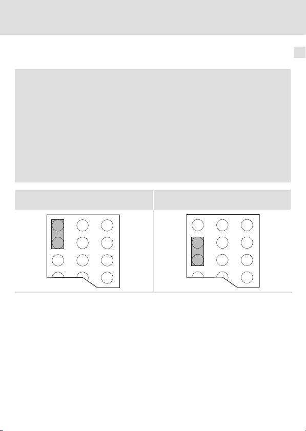
Internal voltage supply
Note!
Internal voltage supply has been selected in the case of standard devices with
an extended AIF interface opening (e.g. front of 8200 vector). The area shown
on a grey background in the graphic marks the jumper position.
ƒ By default, this is not supplied internally in the standard device.
ƒ For internal voltage supply place the jumper on the position indicated
below.
In the case of all other device series (9300, ECS), voltage is always supplied
from the standard device.
(Only external voltage supply possible.)
Lenze setting
64
Internal voltage supply
EDKMF2102 DE/EN/FR 8.0
Page 65

Electrical installation
Connection terminals
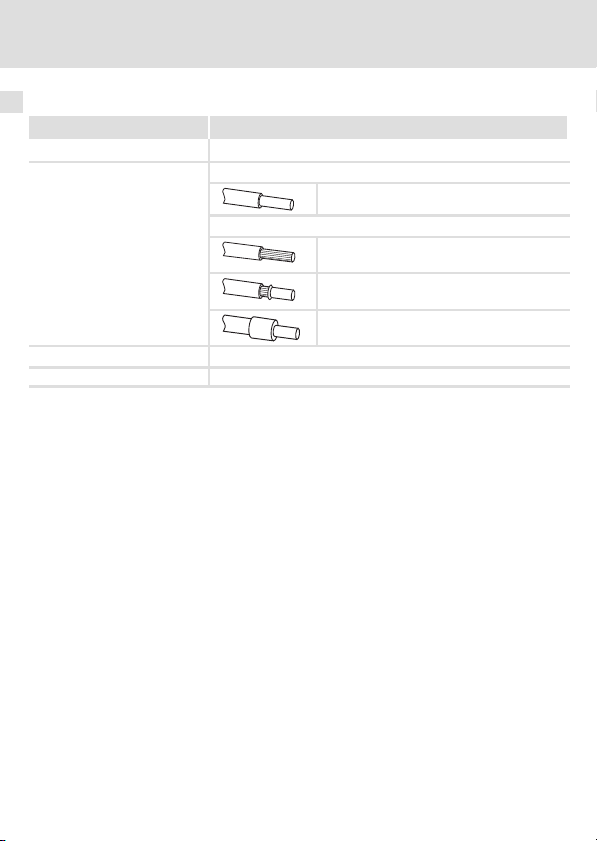
Area Values
Electrical connection Plug connector with screw connection
Possible connections
Tightening torque 0.5 ... 0.6 Nm (4.4 ... 5.3 lb−in)
Stripping length 6 mm
rigid:
flexible:
2
1.5 mm
(AWG 16)
without wire end ferrule
2
(AWG 16)
1.5 mm
with wire end ferrule, without plastic sleeve
2
(AWG 16)
1.5 mm
with wire end ferrule, with plastic sleeve
2
(AWG 16)
1.5 mm
Connection terminals
6
EDKMF2102 DE/EN/FR 8.0
65
Page 66

6 Electrical installation
Connection established via RS232 (LECOM−A)
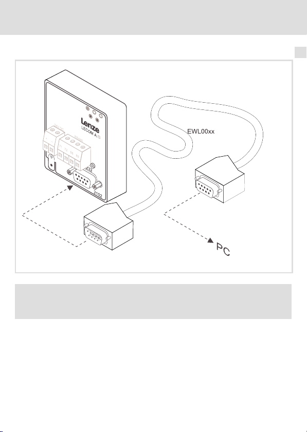
Connection established via RS232 (LECOM−A)
Note!
Use a prefabricated PC system cable (EWL00xx).
2102LEC009
66
EDKMF2102 DE/EN/FR 8.0
Page 67

5
RS232
Connection established via RS232 (LECOM−A)
Electrical installation
1
6
9
RS232 interface for communication module EMF2102IBC−V001 / −V004 (Sub−D socket,
9−pole)
Pin Designation Input/output Assignment
1− − unused
2 RxD Input RS232 data receive line
3 TxD Output RS232 data transmit line
4 DTR Output Transmit control
5 GND − Reference potential
6 DSR Input RS232, unused
7 T/R(A) Input/output RS485 (2102−V001 only)
8 T/R(B) Input/output RS485 (2102−V001 only)
9 Vcc5 Output +5V / 10 mA supply
Features of wiring for RS232
Communication media RS232 (LECOM−A)
Network topology Point−to−Point
Possible number of drive controllers 1
Maximum cable length 15 m
6
2102
2102LEC015
EDKMF2102 DE/EN/FR 8.0
67
Page 68

6 Electrical installation
C
EMF2102IBC−V004 with diagnosis terminal (LECOM−A)
EMF2102IBC−V004 with diagnosis terminal (LECOM−A)
2
E82ZWLxxx
3
AIF
8200 motec
Note!
Use a prefabricated PC system cable (EWL00xx).
1
EWL00xx
P
2102LEC016
68
EDKMF2102 DE/EN/FR 8.0
Page 69

EMF2102IBC−V004 with diagnosis terminal (LECOM−A)
How to wire the components:
1. Connect communication module to PC via PC system cable .
2. Insert connecting cable into diagnosis terminal.
3. Remove plug from heatsink.
4. Insert connecting cable into the AIF interface of the controller.
5. If the mains voltage is switched on, the communication module is now ready for
operation.
You can now communicate with the controller for commissioning, i.e. you can read all codes
and change the writable codes.
Note!
The communication module can be plugged in, removed and parameterised
during operation.
Electrical installation
6
EDKMF2102 DE/EN/FR 8.0
69
Page 70

6 Electrical installation
Connection established via RS485 (LECOM−B)
Connection established via RS485 (LECOM−B)
2102LEC010
Note!
Please always use shielded and twisted pair cables when wiring the RS485
interface cable!
70
EDKMF2102 DE/EN/FR 8.0
Page 71

Connection established via RS485 (LECOM−B)
Electrical installation
RS485 interface via plug connector, 4−pole
Terminal Designation Assignment
71 T/R(B) RS485
72 T/R(A) RS485
88 S−C Capacitive shielding to PE
89 S Direct shielding to PE
6
2102LEC018
EDKMF2102 DE/EN/FR 8.0
71
Page 72

6 Electrical installation
+
_
+
_
Connection established via RS485 (LECOM−B)
IPC/SPS
T/R(B)
T/R(A)
L
A/
LECOM B A/
24V DC
RS485
88
89
72
71
RS232
PE
2102
24V DC
71
L
LECOM B
RS485
88
72
RS232
89
2102
2102LEC011
Connection between two drive controllers
ƒ Connect cable shield to terminal 89 (direct PE) of the first communication module
and terminal 88 (capacitive PE) of the other communication module. This prevents
the flow of potential equalization currents via the cable shield.
ƒ Connect terminals 71 and 72 between the communication modules via a twisted pair
of cables (e.g. green and yellow).
Direct connection to host
ƒ Connect cable shield to PE on the host side and to terminal 88 on the controller side.
This prevents the flow of potential equalization currents via the cable shield.
72
EDKMF2102 DE/EN/FR 8.0
Page 73

Connection established via optical fibre (LECOM−LI)
Electrical installation
Connection established via optical fibre (LECOM−LI)
Features of wiring for optical fibre
Communication media Optical fibre (plastic)
Network topology Ring
Possible number of drive controllers 52
Maximum cable length
l 0 to 40 m at normal output power (S1 = OFF)
l 10 to 66 m at high output power (S1 = ON)
6
2102LEC012
EDKMF2102 DE/EN/FR 8.0
73
Page 74

6 Electrical installation
Connection established via optical fibre (LECOM−LI)
Preparing the optical fibre cable for wiring
Trimming the optical fibre cable
Optical fibre cables can be trimmed without the need for special tools.
1. Place optical fibre cable on a hard surface and cut to required length using a knife, for
example.
2. In case of optical fibre cables with a PUR sheath (red), strip about 20 mm (PE material
does not need to be stripped).
Note!
If the ends of the optical fibre cable are not polished, the maximum cable
length is reduced by 20% (typically). Therefore, please polish the ends of the
optical fibre cable (grain: P1000) .
Installing the optical fibre cable
1. Undo the optical fibre cable compression fitting.
2. Insert end of optical fibre cable into optical fibre connector as far as it will go.
3. Tighten the optical fibre cable compression fitting.
Setting up the optical fibre cable ring
Note!
Do not use bending radii less than 30 mm, otherwise the maximum optical
fibre cable length is reduced by 50% for each bend (typically).
1. Connect white optical fibre connector (transmitter, TxD) of host to black optical fibre
connector (receiver, RxD) of next drive controller.
2. Connect white optical fibre connector of drive controller to black optical fibre
connector of next drive controller.
3. Connect white optical fibre connector of final drive controller to black optical fibre
connector of host.
4. Select high output power if the optical fibre cable between two drive controllers is
longer than 40 m. This is done by moving switch S1 to ON. The maximum cable
length is thus increased to 66 m (with a cable attenuation of 150 dB/km).
74
EDKMF2102 DE/EN/FR 8.0
Page 75

Commissioning
Before switching on
7 Commissioning
Before switching on
Stop!
Before switching on the standard device with the communication module for
the first time, ...
ƒ check the entire wiring with regard to completeness, short circuit, and
earth fault;
ƒ when using the communication module EMF2102IBC−V003 (LECOM−LI),
check the position of the selector for the required output power (73).
7
EDKMF2102 DE/EN/FR 8.0
75
Page 76

7 Commissioning
Commissioning for 8200 series standard devices
Commissioning for 8200 series standard devices
Step Procedure Detailed
1.
Switch on the mains voltage and, if necessary, the external voltage
supply of the communication module.
l After approx. 1 second the standard device will be ready for
operation.
Reaction
l The green voltage supply LED on the front of the communication
module must be ON.
l The drive controller status indicator must be ON or flashing.
Note concerning step 2. and step 3.
Please note that the host parameters must be adapted to the selected baud rate and device address.
Unless this is done, the host will not recognise the reply when the baud rate is changed (C0125), since
this is already being transmitted at the new baud rate by the drive controller.
2.
Set the baud rate.
l Set the baud rate (LECOM baud rate) in code C0125.
l The baud rate setting must be identical for all bus nodes.
l The value can be selected e.g. via the Keypad XT.
l Changes in this code are effective immediately.
Lenze setting: 9600 kBits/sec.
3.
Assign the device address
l Use code C0009 to assign a unique device address to every node
of the network. Only in this way can the host definitely access a
certain controller.
l The values 00, 10, 20, 30,, 90 must not be set. They are
reserved for group addressing.
l The value can be selected e.g. via the Keypad XT.
l Changes in this code are effective immediately.
Lenze setting: 1
information
82
Documentation
for the respective
controller
76
EDKMF2102 DE/EN/FR 8.0
Page 77

Commissioning for 8200 series standard devices
Commissioning
7
ProcedureStep
It is now possible to communicate with any controller, i.e. all codes can be read and all writable codes
can be changed.
4.
Make other necessary controller settings.
Commissioning of the controller
l Select the frequency setpoint with C0046 and the control word
with C0135.
l Set the operating mode C0001= 3.
l With speed setpoint = 0, quick stop (QSP) is active in this
operating mode at switch−on. This prevents uncontrolled starting
of the controller.
– Deactivation of the QSP function: Set C0135/bit 3 = 0 (FALSE).
Detailed
information
Documentation
for the respective
controller
EDKMF2102 DE/EN/FR 8.0
77
Page 78

7 Commissioning
Commissioning for 9300 series standard devices
Commissioning for 9300 series standard devices
Step Procedure Detailed
1.
Switch on the mains voltage and, if necessary, the external voltage
supply of the communication module.
l After approx. 1 second the standard device will be ready for
operation.
Reaction
l The green voltage supply LED on the front of the communication
module must be ON.
l The drive controller status indicator must be ON or flashing.
Note concerning step 2. and step 3.
Please note that the host parameters must be adapted to the selected baud rate and device address.
Unless this is done, the host will not recognise the reply when the baud rate is changed (C0125), since
this is already being transmitted at the new baud rate by the drive controller.
2.
Set the baud rate.
l Set the baud rate (LECOM baud rate) in code C0125.
l The baud rate setting must be identical for all bus nodes.
l The value can be selected e.g. via the Keypad XT.
l Changes in this code are effective immediately.
Lenze setting: 9600 kBits/sec.
3.
Assign the device address
l Use code C0009 to assign a unique device address to every node
of the network. Only in this way can the host definitely access a
certain controller.
l The values 00, 10, 20, 30,, 90 must not be set. They are
reserved for group addressing.
l The value can be selected e.g. via the Keypad XT.
l Changes in this code are effective immediately.
Lenze setting: 1
It is now possible to communicate with any controller, i.e. all codes can be read and all writable codes
can be changed.
information
82
Documentation
for the respective
controller
78
EDKMF2102 DE/EN/FR 8.0
Page 79

Commissioning for 9300 series standard devices
Commissioning
7
ProcedureStep
4.
Make other necessary controller settings.
Commissioning of the controller
l For initial commissioning set code C0005 = 1011 (signal
configuration: speed control via AIF).
l Enable the controller.
– Terminal 28 (RFR: controller enable) is always active and has
to be HIGH during operation. Otherwise the controller will be
inhibited.
l Select the speed setpoint with C0141 in % of n
C0011).
Note
With the signal configuration C0005=xx11, terminal A1 is switched
as a voltage output. This means that only the following terminals
should be connected:
l X5.A1 to X5.28 (Controller enable)
l X5.A1 to X5.E1 (Clockwise rotation / QSP)
max
(value in
Detailed
information
Documentation
for the respective
controller
EDKMF2102 DE/EN/FR 8.0
79
Page 80

7 Commissioning
Commissioning for ECS series standard devices
Commissioning for ECS series standard devices
Step Procedure Detailed
1.
Switch on the mains voltage and, if necessary, the external voltage
supply of the communication module.
l After approx. 1 second the standard device will be ready for
operation.
Reaction
l The green voltage supply LED on the front of the communication
module must be ON.
l The drive controller status indicator must be ON or flashing.
Note concerning step 2. and step 3.
Please note that the host parameters must be adapted to the selected baud rate and device address.
Unless this is done, the host will not recognise the reply when the baud rate is changed (C0125), since
this is already being transmitted at the new baud rate by the drive controller.
2.
Set the baud rate.
l Set the baud rate (LECOM baud rate) in code C0125.
l The baud rate setting must be identical for all bus nodes.
l The value can be selected e.g. via the Keypad XT.
l Changes in this code are effective immediately.
Lenze setting: 9600 kBits/sec.
3.
Assign the device address
l Use code C0009 to assign a unique device address to every node
of the network. Only in this way can the host definitely access a
certain controller.
l The values 00, 10, 20, 30,, 90 must not be set. They are
reserved for group addressing.
l The value can be selected e.g. via the Keypad XT.
l Changes in this code are effective immediately.
Lenze setting: 1
It is now possible to communicate with any controller, i.e. all codes can be read and all writable codes
can be changed.
information
82
Documentation
for the respective
controller
80
EDKMF2102 DE/EN/FR 8.0
Page 81

Commissioning for ECS series standard devices
Commissioning
7
ProcedureStep
4.
Make other necessary controller settings.
Commissioning of the controller
l For initial commissioning set code C0005 = 1003 (signal
configuration: speed control via AIF).
l Enable the controller.
– Terminals SI1 (controller enable) and SI2 (pulse inhibit) are
always active and have to be HIGH during operation.
Otherwise the controller will be inhibited.
Note
The controller must always be externally supplied with 24 V DC.
Detailed
information
Documentation
for the respective
controller
EDKMF2102 DE/EN/FR 8.0
81
Page 82

8 Diagnostics
LED status displays
8 Diagnostics
LED status displays
Pos. Colour Status Description
Green
On The communication module is supplied with voltage and has a
Off The communication module is not supplied with voltage. The
Blinking The communication module is supplied with voltage, but is not (yet)
Yellow Blinking The controller receives a telegram.
Yellow Blinking The controller sends a telegram.
Red /
On /
green
blinking
connection to the drive controller.
controller or the external voltage supply is switched off.
connected to the controller because ...
l the communication module has not been correctly attached to the
controller;
l data transfer to/from the controller is not yet possible (e.g.
controller is in initialisation mode).
The red and green drive LEDs indicate the operating status of the 82XX,
8200 vector, 93XX, 9300 Servo PLC and Drive PLC standard device (see
operating instructions for the standard device).
82
EDKMF2102 DE/EN/FR 8.0
Page 83

Diagnostics
LED status displays
8
EDKMF2102 DE/EN/FR 8.0
83
Page 84

2102LEC001b 2102LEC002b
2102LEC003b 2102LEC004b
0Fig. 0Tab. 0
84
2102LEC007 E82ZBLC001C
EDKMF2102 DE/EN/FR 8.0
Page 85

Pos. Description Informations
Module de communication EMF2102IBC−V001, LECOM−A/B (RS232/RS485)
Module de communication −V002, LECOM−B (RS485)
Module de communication EMF2102IBC−V003, LECOM−LI (fibre optique)
Module de communication EMF2102IBC−V004, LECOM−A (RS232)
E82ZBL−C : module de communication EMF2102IBC−V004, LECOM−A (RS232)
muni d’un clavier de commande avec support
Affichage d’état (vert) : alimentation
Affichage d’état (jaune) : réception de données
Affichage d’état (jaune) : envoi de données
Affichage d’état (rouge/vert) : variateur
Bornier, raccordement pour alimentation externe
Bornier RS485, raccordement de l’interface RS485
Prise Sub−D RS232, raccordement de l’interface RS232
Vis de fixation
Raccordement PE (uniquement pour 82XX)
Commutateur débit (normal/élevé)
Récepteur fibre optique (noir)
Emetteur fibre optique (blanc)
Plaque signalétique 95
détaillées
108
122
103
111
107
113
113
EDKMF2102 DE/EN/FR 8.0
85
Page 86

i Sommaire
1 Présentation du document 87. . . . . . . . . . . . . . . . . . . . . . . . . . . . . . . . . . . . . . . . . . .
Conventions utilisées 88. . . . . . . . . . . . . . . . . . . . . . . . . . . . . . . . . . . . . . . . . . . . . . .
Consignes utilisées 89. . . . . . . . . . . . . . . . . . . . . . . . . . . . . . . . . . . . . . . . . . . . . . . . .
2 Consignes de sécurité 91. . . . . . . . . . . . . . . . . . . . . . . . . . . . . . . . . . . . . . . . . . . . . . .
3 Description du produit 92. . . . . . . . . . . . . . . . . . . . . . . . . . . . . . . . . . . . . . . . . . . . . .
Fonction 92. . . . . . . . . . . . . . . . . . . . . . . . . . . . . . . . . . . . . . . . . . . . . . . . . . . . . . . . .
Utilisation conforme à la fonction 92. . . . . . . . . . . . . . . . . . . . . . . . . . . . . . . . . . . .
Équipement livré> 94. . . . . . . . . . . . . . . . . . . . . . . . . . . . . . . . . . . . . . . . . . . . . . . . . .
Identification 95. . . . . . . . . . . . . . . . . . . . . . . . . . . . . . . . . . . . . . . . . . . . . . . . . . . . . .
4 Spécifications techniques 96. . . . . . . . . . . . . . . . . . . . . . . . . . . . . . . . . . . . . . . . . . .
Caractéristiques générales et conditions d’utilisation 96. . . . . . . . . . . . . . . . . . . .
Isolement de protection 97. . . . . . . . . . . . . . . . . . . . . . . . . . . . . . . . . . . . . . . . . . . . .
Encombrements 98. . . . . . . . . . . . . . . . . . . . . . . . . . . . . . . . . . . . . . . . . . . . . . . . . . .
5 Installation mécanique 99. . . . . . . . . . . . . . . . . . . . . . . . . . . . . . . . . . . . . . . . . . . . . .
6 Installation électrique 100. . . . . . . . . . . . . . . . . . . . . . . . . . . . . . . . . . . . . . . . . . . . . . .
Raccordement à un maître 100. . . . . . . . . . . . . . . . . . . . . . . . . . . . . . . . . . . . . . . . . . .
Câblage conforme CEM 102. . . . . . . . . . . . . . . . . . . . . . . . . . . . . . . . . . . . . . . . . . . . . .
Alimentation 103. . . . . . . . . . . . . . . . . . . . . . . . . . . . . . . . . . . . . . . . . . . . . . . . . . . . .
Spécifications des bornes de raccordement 105. . . . . . . . . . . . . . . . . . . . . . . . . . . . .
Liaison via RS232 (LECOM−A) 106. . . . . . . . . . . . . . . . . . . . . . . . . . . . . . . . . . . . . . . . .
EMF2102IBC−V004 avec clavier de commande et support (LECOM−A) 108. . . . . . . .
Liaison via RS485 (LECOM−B) 110. . . . . . . . . . . . . . . . . . . . . . . . . . . . . . . . . . . . . . . . .
Liaison via fibre optique (LECOM−LI) 113. . . . . . . . . . . . . . . . . . . . . . . . . . . . . . . . . . .
7 Mise en service 115. . . . . . . . . . . . . . . . . . . . . . . . . . . . . . . . . . . . . . . . . . . . . . . . . . . .
Avant la première mise sous tension 115. . . . . . . . . . . . . . . . . . . . . . . . . . . . . . . . . . .
Mise en service avec les appareils de base de la série 8200 116. . . . . . . . . . . . . . . . .
Mise en service avec les appareils de base de la série 9300 118. . . . . . . . . . . . . . . . .
Mise en service avec les appareils de base de la série ECS 120. . . . . . . . . . . . . . . . . .
8 Diagnostic 122. . . . . . . . . . . . . . . . . . . . . . . . . . . . . . . . . . . . . . . . . . . . . . . . . . . . . . . .
Affichages d’état par LED 122. . . . . . . . . . . . . . . . . . . . . . . . . . . . . . . . . . . . . . . . . . .
86
EDKMF2102 DE/EN/FR 8.0
Page 87

Présentation du document 1
1 Présentation du document
Contenu
La présente documentation contient ...
ƒ des consignes de sécurité à respecter impérativement ;
ƒ des renseignements sur les versions d’appareils de base Lenze à utiliser ;
ƒ des informations sur l’installation mécanique et électrique du module de
communication
ƒ des informations sur la mise en service et le diagnostic.
Validité
Les informations contenues dans le présent document s’appliquent aux appareils suivants :
ƒ Modules de communication EMF2102IBC−V00X / E82ZBL−C à partir de la version
3x.3x.
Public visé
Cette documentation s’adresse aux personnes chargées de la conception, de l’installation,
de la mise en service et de mise en réseau et de la télémaintenance d’une machine.
Conseil !
Toutes les informations relatives aux produits Lenze peuvent être téléchargées
sur notre site à l’adresse suivante :
www.Lenze.com
EDKMF2102 DE/EN/FR 8.0
87
Page 88

1 Présentation du document
Conventions utilisées
Conventions utilisées
Pour distinguer les différents types d’information, cette documentation utilise les
conventions suivantes :
Type d’information Aperçu Exemples/remarques
Représentation des chiffres
Séparateur décimal
Pictogrammes
Renvoi à une page
Point Le point décimal est généralement
utilisé.
Exemple : 1234.56
Renvoi à une autre page présentant
des informations supplémentaires
Exemple : 16 = voir page 16
88
EDKMF2102 DE/EN/FR 8.0
Page 89

Présentation du document
Consignes utilisées
Consignes utilisées
Pour indiquer des risques et des informations importantes, la présente documentation
utilise les mots et pictogrammes suivants :
Consignes de sécurité
Présentation des consignes de sécurité
Danger !
(Le pictogramme indique le type de risque.)
Explication
(L’explication décrit le risque et les moyens de l’éviter.)
Pictogramme et mot associé Explication
Situation dangereuse pour les personnes en raison d’une
tension électrique élevée
Danger !
Danger !
Stop !
Indication d’un danger imminent qui peut avoir pour
conséquences des blessures mortelles ou très graves en
cas de non−respect des consignes de sécurité
correspondantes
Situation dangereuse pour les personnes en raison d’un
danger d’ordre général
Indication d’un danger imminent qui peut avoir pour
conséquences des blessures mortelles ou très graves en
cas de non−respect des consignes de sécurité
correspondantes
Risques de dégâts matériels
Indication d’un risque potentiel qui peut avoir pour
conséquences des dégâts matériels en cas de non−respect
des consignes de sécurité correspondantes
1
EDKMF2102 DE/EN/FR 8.0
89
Page 90

1 Présentation du document
Consignes utilisées
Consignes d’utilisation
Pictogramme et mot associé Explication
Remarque
importante !
Conseil !
Remarque importante pour assurer un fonctionnement
correct
Conseil utile pour faciliter la mise en uvre
Renvoi à une autre documentation
90
EDKMF2102 DE/EN/FR 8.0
Page 91

Consignes de sécurité 2
2 Consignes de sécurité
Danger !
Toute utilisation non conforme à la fonction du module de communication et
de l’appareil de base risque d’entraîner des blessures graves et des dommages
matériels.
Tenir compte des consignes de sécurité et des dangers résiduels indiqués dans
la documentation de l’appareil de base.
Stop !
Décharge électrostatique
Des composants électroniques à l’intérieur du module de communication
peuvent être endommagés ou détruits par des décharges électrostatiques.
Risques encourus :
ƒ Le module de communication est endommagé.
ƒ La communication par bus de terrain est impossible ou erronée.
Mesures de protection :
ƒ Se libérer des décharges électrostatiques avant toute manipulation du
module de communication.
EDKMF2102 DE/EN/FR 8.0
91
Page 92

3 Description du produit
Fonction
3 Description du produit
Fonction
Le module de communication 2102−Vxxx / E82ZBL−C permet d’établir la liaison avec des
appareils de base Lenze par câble(RS232/485−Interface) ou par fibre optique.
Utilisation conforme à la fonction
Le module de communication EMF2102IBC−Vxxx / E82ZBL−C ...
ƒ est un matériel d’exploitation destiné à être utilisé dans les installations industrielles
à courant fort ;
ƒ est un accessoire compatible avec les appareils de base Lenze suivants :
Type d’appareil V001 V002 V003 V004 E82ZBL−C
Convertisseur de fréquence 8200
– 33.820XE.2x.1x
– 33.820XC.2x.1x
– 33.821XE.2x.2x
– 33.821XC.2x.2x
– 33.822XE.1x.1x
– 33.824XE.1x.1x
– 33.824XC.1x.1x
Convertisseur de fréquence 8200 vector
– E82EVxxxKxBxxxXXVx14
Convertisseur de fréquence 8200 motec
– E82MVxxxxxBxxxXXVx14
Démarreur moteur LCU
– ELCAMxIxxx4SNNPSNN
Servosystème ECS
– ECSxPxxxx4xxxxXX1A60
– ECSxSxxxx4xxxxXX1A60
– ECSxMxxxx4xxxxXX1A60
– ECSxAxxxx4xxxxXX1A23
– ECSxExxxxC4xXXXVA12
1)
Alimentation du module de communication uniquement via une source de tension externe
1)
1)
1)
1)
1)
1)
92
EDKMF2102 DE/EN/FR 8.0
Page 93

Description du produit
Utilisation conforme à la fonction
Drive PLC
– EPL10200 E 1x.20
Servovariateur 9300
– 33.93XXxE.2x.1x
– 33.93XXxC.2x.1x
Convertisseur de fréquence 9300
– 33.93XXVE.2x.1x
9300 Servo PLC
– 33.93XXEI 2x.0x, 33.93XXET 2x.0x
– 33.93XXCI 2x.0x, 33.93XXCT 2x.0x
1)
Alimentation du module de communication uniquement via une source de tension externe
Toute autre utilisation est contre−indiquée !
3
E82ZBL−CV004V003V002V001Type d’appareil
EDKMF2102 DE/EN/FR 8.0
93
Page 94

3 Description du produit
Équipement livré
Équipement livré>
Pos. Module de communication EMF2102IBC V001 V002 V003 V004 Voir
Bornier à vis, 2 bornes
Bornier à vis, à 4 bornes
Instructions de montage
Accessoires (non compris dans l’équipement livré)
ƒ Câble système pour PC EWL00xx
ƒ Câble de liaison E82ZWLxxx
ƒ Logiciel de paramétrage "Global Drive Control (GDC)", à partir de la version 3.2
89
88
72
71
2102LEC008, E82ZAFX025, 026, 8200VEC063
l l l
l l
l l l l
Conseil !
Pour plus d’informations sur le module de communication, consulter le
manuel de communication correspondant.
Le fichier au format PDF peut être téléchargé à l’adresse suivante :
http://www.Lenze.com
105
94
EDKMF2102 DE/EN/FR 8.0
Page 95

Identification
L
Type
Id.-No.
Prod.-No.
Ser.-No.
Description du produit
Identification
3
E82AF000P0B201XX
Série d’appareils LECOM
Version matérielle
Version logicielle
Variante
001 : interface RS485/232
002 : interface RS485
003 : interface fibre optique
004 : interface RS232
EDKMF2102 DE/EN/FR 8.0
33.2102IBC 3x 3x V00x
99371BC013
95
Page 96

4 Spécifications techniques
Caractéristiques générales et conditions d’utilisation
4 Spécifications techniques
Caractéristiques générales et conditions d’utilisation
Plage
Support de
communication
Consommation de
courant
Protocole LECOM−A/B V2.0
Format de caractère
de transmission
Vitesse de
transmission [bits/s]
Indice de protection IP20
Température
ambiante
Conditions
climatiques
Alimentation externe CC (connecteur à broches 24V CC)
U
= 15 à 30 V CC ; w = 5%
eff
= 20 à 25 V CC; w = 48% ; Uss < 35 V
U
eff
Module de communication EMF2102IBC
−V001 −V002 −V003 −V004 /
RS232 (LECOM−A)
RS485 (LECOM−B)
80 mA 60 mA 70 mA −
7 bit ASCII ; 1 bit d’arrêt ; 1 bit de démarrage ; 1 bit de parité (paire)
1200, 2400, 4800, 9600, 19200
Fonctionnement : 0°C à +55 °C
Transport : − 25°C à +70 °C
Stockage : − 25°C ... +60 °C
classe 3K3 selon EN 50178
(sans condensation, humidité relative moyenne 85 %)
RS485 (LECOM−B) Fibre optique
(LECOM−LI)
E82ZBL−C
RS232 (LECOM−A)
96
EDKMF2102 DE/EN/FR 8.0
Page 97

Spécifications techniques
Isolement de protection
Isolement de protection
Isolement de protection entre
bus et...
point de terre / PE Isolement fonctionnel Non
alimentation externe Isolement fonctionnel Isolement
partie puissance
820X / 821X Isolement principal
822X / 8200 vector
93XX / 9300 Servo PLC
servosystème ECS
bornes de commande
820X / 8200 vector
821X
822x
Drive PLC
93XX / 9300 Servo PLC
servosystème ECS Isolement renforcé Isolement renforcé
Type d’isolement pour les modules de communication EMF2102IBC
−V001 −V002 −V003 −V004 / E82ZBL−C
obligatoire
renforcé
Isolement
Isolement renforcé Isolement renforcé
Isolement fonctionnel Isolement
Isolement principal Isolement principal
renforcé
renforcé
Isolement
fonctionnel
−
Isolement principal
Isolement
fonctionnel
4
EDKMF2102 DE/EN/FR 8.0
97
Page 98

4 Spécifications techniques
+
_
Encombrements
Encombrements
IN
ON
OUT
S1
OFF
24V DC
84
b
b1
75
RS485
_
72
71
+
L
A/B/LI
LECOM
88
89
RS232
2102
a61 mm
b 83 mm (uniquement EMF2102IBC−V003, LECOM−LI)
b1 75 mm
e 28 mm
e1 18 mm
98
61
a
e1
18
28
e
2102LEC013
EDKMF2102 DE/EN/FR 8.0
Page 99

Installation mécanique 5
5 Installation mécanique
2102LEC014
Fig. 1 Brancher le module de communication
ƒ Enficher le module de communication dans l’appareil de base (ici : 8200 vector).
ƒ Visser le module de communication sur l’appareil de base à l’aide de la vis de fixation
pour assurer une bonne liaison avec la terre.
Remarque importante !
Pour l’alimentation interne du module de communication par le convertisseur
de fréquence 8200 vector, le cavalier doit être inséré dans l’ouverture prévue à
cet effet (voir schéma ci−dessus).
Voir également les remarques fournies (104).
EDKMF2102 DE/EN/FR 8.0
99
Page 100

6 Installation électrique
Raccordement à un maître
6 Installation électrique
Raccordement à un maître
Danger !
Prévoir une séparation du potentiel supplémentaire dans les cas suivants :
ƒ Un variateur de vitesse 820X et 821X est raccordé à un système maître et
ƒ une séparation sûre du potentiel (isolement renforcé) selon EN 61800−5−1
est nécessaire.
Recommandations générales concernant le câblage :
1. Respecter la topologie de bus : ne pas utiliser de câbles de dérivation.
2. Utiliser un câble LECOM conforme aux spécifications fournies.
100
EDKMF2102 DE/EN/FR 8.0
 Loading...