

Page 1

EDS94SPP101
.W@D
Ä.W@Dä
L−force Drives
Hardware Manual
9400
E94A..., E94B...
Servo Drives 9400
Page 2

0Fig. 0Tab. 0
Page 3

Contents i
1 Preface 10. . . . . . . . . . . . . . . . . . . . . . . . . . . . . . . . . . . . . . . . . . . . . . . . . . . . . . . . . . . . . . . . . .
1.1 The 9400 Servo Drives product range 10. . . . . . . . . . . . . . . . . . . . . . . . . . . . . . . . . . . .
1.1.1 The system 10. . . . . . . . . . . . . . . . . . . . . . . . . . . . . . . . . . . . . . . . . . . . . . . . . .
1.1.2 Features 10. . . . . . . . . . . . . . . . . . . . . . . . . . . . . . . . . . . . . . . . . . . . . . . . . . . . .
1.1.3 System overview 10. . . . . . . . . . . . . . . . . . . . . . . . . . . . . . . . . . . . . . . . . . . . . .
1.2 About this Hardware Manual 12. . . . . . . . . . . . . . . . . . . . . . . . . . . . . . . . . . . . . . . . . . .
1.2.1 Information provided by the Hardware Manual 12. . . . . . . . . . . . . . . . . . . .
1.2.2 Products to which the Hardware Manual applies 13. . . . . . . . . . . . . . . . . . .
1.3 Document history 17. . . . . . . . . . . . . . . . . . . . . . . . . . . . . . . . . . . . . . . . . . . . . . . . . . . .
1.4 Conventions used 18. . . . . . . . . . . . . . . . . . . . . . . . . . . . . . . . . . . . . . . . . . . . . . . . . . . .
1.5 Notes used 19. . . . . . . . . . . . . . . . . . . . . . . . . . . . . . . . . . . . . . . . . . . . . . . . . . . . . . . . . .
1.6 Legal regulations 20. . . . . . . . . . . . . . . . . . . . . . . . . . . . . . . . . . . . . . . . . . . . . . . . . . . . .
1.7 Terms and abbreviations used 22. . . . . . . . . . . . . . . . . . . . . . . . . . . . . . . . . . . . . . . . . .
2 Safety instructions 24. . . . . . . . . . . . . . . . . . . . . . . . . . . . . . . . . . . . . . . . . . . . . . . . . . . . . . . . .
2.1 General safety and application notes for Lenze controllers 24. . . . . . . . . . . . . . . . . .
2.2 General safety and application notes for Lenze motors 27. . . . . . . . . . . . . . . . . . . . .
2.3 Residual hazards 30. . . . . . . . . . . . . . . . . . . . . . . . . . . . . . . . . . . . . . . . . . . . . . . . . . . . .
3 Single−axis controllers 31. . . . . . . . . . . . . . . . . . . . . . . . . . . . . . . . . . . . . . . . . . . . . . . . . . . . . .
3.1 Device features 31. . . . . . . . . . . . . . . . . . . . . . . . . . . . . . . . . . . . . . . . . . . . . . . . . . . . . .
3.2 Overview of the devices 32. . . . . . . . . . . . . . . . . . . . . . . . . . . . . . . . . . . . . . . . . . . . . . .
3.3 General data and operating conditions 33. . . . . . . . . . . . . . . . . . . . . . . . . . . . . . . . .
3.4 Rated data 42. . . . . . . . . . . . . . . . . . . . . . . . . . . . . . . . . . . . . . . . . . . . . . . . . . . . . . . . . .
3.4.1 Overview 43. . . . . . . . . . . . . . . . . . . . . . . . . . . . . . . . . . . . . . . . . . . . . . . . . . . .
3.4.2 Operation at rated mains voltage 230 V 46. . . . . . . . . . . . . . . . . . . . . . . . . .
3.4.3 Operation at rated mains voltage 400 V 49. . . . . . . . . . . . . . . . . . . . . . . . . .
3.4.4 Operation with rated mains voltage 480 V 55. . . . . . . . . . . . . . . . . . . . . . . .
3.4.5 Fuses and cable cross−sections 61. . . . . . . . . . . . . . . . . . . . . . . . . . . . . . . . . .
3.4.6 Overcurrent operation 65. . . . . . . . . . . . . . . . . . . . . . . . . . . . . . . . . . . . . . . . .
3.4.7 Current−time diagrams 71. . . . . . . . . . . . . . . . . . . . . . . . . . . . . . . . . . . . . . . .
3.5 Device description 80. . . . . . . . . . . . . . . . . . . . . . . . . . . . . . . . . . . . . . . . . . . . . . . . . . . .
3.5.1 Devices in the range 2 ... 24 A (0.37 ... 11 kW) 80. . . . . . . . . . . . . . . . . . . . . .
3.5.2 Devices in the range 32 ... 104 A (15 ... 55 kW) 82. . . . . . . . . . . . . . . . . . . . .
3.5.3 Devices in the range 145 ... 245 A (75 ... 130 kW) 84. . . . . . . . . . . . . . . . . . .
3.5.4 Device 292 A (150 kW) 86. . . . . . . . . . . . . . . . . . . . . . . . . . . . . . . . . . . . . . . . .
3.5.5 Devices in the range 366 ... 460 A (190 ... 240 kW) 88. . . . . . . . . . . . . . . . . .
EDS94SPP101 EN 10.2
3
Page 4

Contentsi
3.6 Mechanical installation 90. . . . . . . . . . . . . . . . . . . . . . . . . . . . . . . . . . . . . . . . . . . . . . . .
3.6.1 Important notes 90. . . . . . . . . . . . . . . . . . . . . . . . . . . . . . . . . . . . . . . . . . . . . .
3.6.2 Devices in the range 2 ... 24 A (0.37 ... 11 kW) 91. . . . . . . . . . . . . . . . . . . . . .
3.6.3 Devices in the range 32 ... 104 A (15 ... 55 kW) 94. . . . . . . . . . . . . . . . . . . . .
3.6.4 Devices in the range 145 ... 292 A (75 ... 150 kW) 95. . . . . . . . . . . . . . . . . . .
3.6.5 Devices in the range 366 ... 460 A (190 ... 240 kW) 96. . . . . . . . . . . . . . . . . .
3.7 Wiring 97. . . . . . . . . . . . . . . . . . . . . . . . . . . . . . . . . . . . . . . . . . . . . . . . . . . . . . . . . . . . . .
3.7.1 Important notes 97. . . . . . . . . . . . . . . . . . . . . . . . . . . . . . . . . . . . . . . . . . . . . .
3.7.2 Safety instructions for the installation according to UL/CSA 99. . . . . . . . .
3.7.3 Earthing of internal EMC filters 108. . . . . . . . . . . . . . . . . . . . . . . . . . . . . . . . .
3.7.4 Devices in the range 2 ... 24 A (0.37 ... 11 kW) 113. . . . . . . . . . . . . . . . . . . . . .
3.7.5 Devices in the range 32 ... 104 A (15 ... 55 kW) 122. . . . . . . . . . . . . . . . . . . . .
3.7.6 Devices in the range 145 ... 245 A (75 ... 130 kW) 127. . . . . . . . . . . . . . . . . . .
3.7.7 Device 292 A (150 kW) 134. . . . . . . . . . . . . . . . . . . . . . . . . . . . . . . . . . . . . . . . .
3.7.8 Devices in the range 366 ... 460 A (190 ... 240 kW) 140. . . . . . . . . . . . . . . . . .
3.8 Control terminals 146. . . . . . . . . . . . . . . . . . . . . . . . . . . . . . . . . . . . . . . . . . . . . . . . . . . . .
3.9 Device modules 163. . . . . . . . . . . . . . . . . . . . . . . . . . . . . . . . . . . . . . . . . . . . . . . . . . . . . .
3.10 Preparing the commissioning procedure 164. . . . . . . . . . . . . . . . . . . . . . . . . . . . . . . . .
4 Multi−axis controllers 165. . . . . . . . . . . . . . . . . . . . . . . . . . . . . . . . . . . . . . . . . . . . . . . . . . . . . .
4.1 Device features 165. . . . . . . . . . . . . . . . . . . . . . . . . . . . . . . . . . . . . . . . . . . . . . . . . . . . . .
4.2 Overview of the devices 166. . . . . . . . . . . . . . . . . . . . . . . . . . . . . . . . . . . . . . . . . . . . . . .
4.3 General data and operating conditions 167. . . . . . . . . . . . . . . . . . . . . . . . . . . . . . . . .
4.4 Rated data 172. . . . . . . . . . . . . . . . . . . . . . . . . . . . . . . . . . . . . . . . . . . . . . . . . . . . . . . . . .
4.4.1 Overview 172. . . . . . . . . . . . . . . . . . . . . . . . . . . . . . . . . . . . . . . . . . . . . . . . . . . .
4.4.2 Operation in 230−V−AC system 174. . . . . . . . . . . . . . . . . . . . . . . . . . . . . . . . . .
4.4.3 Operation in 400−V−AC system 175. . . . . . . . . . . . . . . . . . . . . . . . . . . . . . . . . .
4.4.4 Operation in 480−V−AC system 176. . . . . . . . . . . . . . . . . . . . . . . . . . . . . . . . . .
4.4.5 Fuses and cable cross−sections 177. . . . . . . . . . . . . . . . . . . . . . . . . . . . . . . . . .
4.4.6 Overcurrent operation 178. . . . . . . . . . . . . . . . . . . . . . . . . . . . . . . . . . . . . . . . .
4.4.7 Current−time diagrams 182. . . . . . . . . . . . . . . . . . . . . . . . . . . . . . . . . . . . . . . .
4.5 Device description 188. . . . . . . . . . . . . . . . . . . . . . . . . . . . . . . . . . . . . . . . . . . . . . . . . . . .
4.5.1 Devices in the range 2 ... 32 A (0.37 ... 15 kW) 188. . . . . . . . . . . . . . . . . . . . . .
4.5.2 Devices in the range 47 ... 59 A (22 ... 30 kW) 190. . . . . . . . . . . . . . . . . . . . . . .
4.6 Mechanical installation 192. . . . . . . . . . . . . . . . . . . . . . . . . . . . . . . . . . . . . . . . . . . . . . . .
4.6.1 Important notes 192. . . . . . . . . . . . . . . . . . . . . . . . . . . . . . . . . . . . . . . . . . . . . .
4.6.2 Devices in the range 2 ... 32 A (0.37 ... 15 kW) 193. . . . . . . . . . . . . . . . . . . . . .
4.6.3 Devices in the range 47 ... 59 A (22 ... 30 kW) 197. . . . . . . . . . . . . . . . . . . . . . .
4
EDS94SPP101 EN 10.2
Page 5

Contents i
4.7 Wiring 198. . . . . . . . . . . . . . . . . . . . . . . . . . . . . . . . . . . . . . . . . . . . . . . . . . . . . . . . . . . . . .
4.7.1 Important notes 198. . . . . . . . . . . . . . . . . . . . . . . . . . . . . . . . . . . . . . . . . . . . . .
4.7.2 Safety instructions for the installation according to UL/CSA 200. . . . . . . . .
4.7.3 Earthing of internal EMC filters 204. . . . . . . . . . . . . . . . . . . . . . . . . . . . . . . . .
4.7.4 Devices in the range 2 ... 32 A (0.37 ... 15 kW) 206. . . . . . . . . . . . . . . . . . . . . .
4.7.5 Devices in the range 47 ... 59 A (22 ... 30 kW) 215. . . . . . . . . . . . . . . . . . . . . . .
4.8 Control terminals 219. . . . . . . . . . . . . . . . . . . . . . . . . . . . . . . . . . . . . . . . . . . . . . . . . . . . .
4.9 Device modules 236. . . . . . . . . . . . . . . . . . . . . . . . . . . . . . . . . . . . . . . . . . . . . . . . . . . . . .
4.10 Preparing the commissioning procedure 237. . . . . . . . . . . . . . . . . . . . . . . . . . . . . . . . .
5 Power supply module 238. . . . . . . . . . . . . . . . . . . . . . . . . . . . . . . . . . . . . . . . . . . . . . . . . . . . . .
5.1 Device features 238. . . . . . . . . . . . . . . . . . . . . . . . . . . . . . . . . . . . . . . . . . . . . . . . . . . . . .
5.2 General data and operating conditions 239. . . . . . . . . . . . . . . . . . . . . . . . . . . . . . . . .
5.3 Rated data 242. . . . . . . . . . . . . . . . . . . . . . . . . . . . . . . . . . . . . . . . . . . . . . . . . . . . . . . . . .
5.3.1 Overview 242. . . . . . . . . . . . . . . . . . . . . . . . . . . . . . . . . . . . . . . . . . . . . . . . . . . .
5.3.2 Operation at rated mains voltage 230 V 243. . . . . . . . . . . . . . . . . . . . . . . . . .
5.3.3 Operation at rated mains voltage 400 V 245. . . . . . . . . . . . . . . . . . . . . . . . . .
5.3.4 Operation with rated mains voltage 480 V 247. . . . . . . . . . . . . . . . . . . . . . . .
5.3.5 Fuses and cable cross−sections 249. . . . . . . . . . . . . . . . . . . . . . . . . . . . . . . . . .
5.3.6 Mains filters for power supply modules 251. . . . . . . . . . . . . . . . . . . . . . . . . .
5.4 Device description 254. . . . . . . . . . . . . . . . . . . . . . . . . . . . . . . . . . . . . . . . . . . . . . . . . . . .
5.4.1 Devices in the range 10 ... 36 A (4 ... 18 kW) 254. . . . . . . . . . . . . . . . . . . . . . . .
5.4.2 Devices in the range 100 ... 245 A (48 ... 119 kW) 256. . . . . . . . . . . . . . . . . . .
5.5 Mechanical installation 258. . . . . . . . . . . . . . . . . . . . . . . . . . . . . . . . . . . . . . . . . . . . . . . .
5.5.1 Important notes 258. . . . . . . . . . . . . . . . . . . . . . . . . . . . . . . . . . . . . . . . . . . . . .
5.5.2 Devices in the range 10 ... 36 A (4 ... 18 kW) 259. . . . . . . . . . . . . . . . . . . . . . . .
5.5.3 Devices in the range 100 ... 245 A (48 ... 119 kW) 263. . . . . . . . . . . . . . . . . . .
5.6 Wiring 267. . . . . . . . . . . . . . . . . . . . . . . . . . . . . . . . . . . . . . . . . . . . . . . . . . . . . . . . . . . . . .
5.6.1 Important notes 267. . . . . . . . . . . . . . . . . . . . . . . . . . . . . . . . . . . . . . . . . . . . . .
5.6.2 Safety instructions for the installation according to UL/CSA 269. . . . . . . . .
5.6.3 Design of the cables 271. . . . . . . . . . . . . . . . . . . . . . . . . . . . . . . . . . . . . . . . . . .
5.6.4 Devices in the range 10 ... 36 A (4 ... 18 kW) 272. . . . . . . . . . . . . . . . . . . . . . . .
5.6.5 Devices in the range 100 ... 245 A (48 ... 119 kW) 276. . . . . . . . . . . . . . . . . . .
5.7 Control terminals 281. . . . . . . . . . . . . . . . . . . . . . . . . . . . . . . . . . . . . . . . . . . . . . . . . . . . .
5.8 Final works 284. . . . . . . . . . . . . . . . . . . . . . . . . . . . . . . . . . . . . . . . . . . . . . . . . . . . . . . . . .
6 Regenerative power supply modules 285. . . . . . . . . . . . . . . . . . . . . . . . . . . . . . . . . . . . . . . . .
6.1 Device features 285. . . . . . . . . . . . . . . . . . . . . . . . . . . . . . . . . . . . . . . . . . . . . . . . . . . . . .
6.2 General data and operating conditions 286. . . . . . . . . . . . . . . . . . . . . . . . . . . . . . . . .
EDS94SPP101 EN 10.2
5
Page 6

Contentsi
6.3 Rated data 289. . . . . . . . . . . . . . . . . . . . . . . . . . . . . . . . . . . . . . . . . . . . . . . . . . . . . . . . . .
6.3.1 Overview 289. . . . . . . . . . . . . . . . . . . . . . . . . . . . . . . . . . . . . . . . . . . . . . . . . . . .
6.3.2 Operation at rated mains voltage 230 V 290. . . . . . . . . . . . . . . . . . . . . . . . . .
6.3.3 Operation at rated mains voltage 400 V 292. . . . . . . . . . . . . . . . . . . . . . . . . .
6.3.4 Operation with rated mains voltage 480 V 294. . . . . . . . . . . . . . . . . . . . . . . .
6.3.5 Regenerative feedback with brake chopper 296. . . . . . . . . . . . . . . . . . . . . . .
6.3.6 Fuses and cable cross−sections 298. . . . . . . . . . . . . . . . . . . . . . . . . . . . . . . . . .
6.3.7 Current−time diagrams 299. . . . . . . . . . . . . . . . . . . . . . . . . . . . . . . . . . . . . . . .
6.3.8 Mains filters for regenerative power supply modules 302. . . . . . . . . . . . . . .
6.4 Device description 305. . . . . . . . . . . . . . . . . . . . . . . . . . . . . . . . . . . . . . . . . . . . . . . . . . . .
6.5 Mechanical installation 309. . . . . . . . . . . . . . . . . . . . . . . . . . . . . . . . . . . . . . . . . . . . . . . .
6.5.1 Important notes 309. . . . . . . . . . . . . . . . . . . . . . . . . . . . . . . . . . . . . . . . . . . . . .
6.5.2 Dimensions 310. . . . . . . . . . . . . . . . . . . . . . . . . . . . . . . . . . . . . . . . . . . . . . . . . .
6.5.3 Arrangement of the devices 313. . . . . . . . . . . . . . . . . . . . . . . . . . . . . . . . . . . .
6.5.4 Mounting steps 314. . . . . . . . . . . . . . . . . . . . . . . . . . . . . . . . . . . . . . . . . . . . . .
6.6 Wiring 315. . . . . . . . . . . . . . . . . . . . . . . . . . . . . . . . . . . . . . . . . . . . . . . . . . . . . . . . . . . . . .
6.6.1 Important notes 315. . . . . . . . . . . . . . . . . . . . . . . . . . . . . . . . . . . . . . . . . . . . . .
6.6.2 Safety instructions for the installation according to UL/CSA 317. . . . . . . . .
6.6.3 Connection plan 319. . . . . . . . . . . . . . . . . . . . . . . . . . . . . . . . . . . . . . . . . . . . . .
6.6.4 Earthing of internal EMC filters 320. . . . . . . . . . . . . . . . . . . . . . . . . . . . . . . . .
6.6.5 Connecting busbars 323. . . . . . . . . . . . . . . . . . . . . . . . . . . . . . . . . . . . . . . . . . .
6.6.6 Design of the cables 324. . . . . . . . . . . . . . . . . . . . . . . . . . . . . . . . . . . . . . . . . . .
6.6.7 How to connect the shield 324. . . . . . . . . . . . . . . . . . . . . . . . . . . . . . . . . . . . . .
6.6.8 Terminal assignment 325. . . . . . . . . . . . . . . . . . . . . . . . . . . . . . . . . . . . . . . . . .
6.6.9 Wiring of control connections 328. . . . . . . . . . . . . . . . . . . . . . . . . . . . . . . . . . .
6.7 Device modules 333. . . . . . . . . . . . . . . . . . . . . . . . . . . . . . . . . . . . . . . . . . . . . . . . . . . . . .
6.8 Final works 334. . . . . . . . . . . . . . . . . . . . . . . . . . . . . . . . . . . . . . . . . . . . . . . . . . . . . . . . . .
6.8.1 Initial commissioning on 400 V mains voltage 334. . . . . . . . . . . . . . . . . . . . .
6.8.2 Initial commissioning on 230 V or 480 V mains voltage 334. . . . . . . . . . . . .
6.8.3 Further settings 334. . . . . . . . . . . . . . . . . . . . . . . . . . . . . . . . . . . . . . . . . . . . . .
7 DC−bus operation 335. . . . . . . . . . . . . . . . . . . . . . . . . . . . . . . . . . . . . . . . . . . . . . . . . . . . . . . . .
7.1 Introduction 335. . . . . . . . . . . . . . . . . . . . . . . . . . . . . . . . . . . . . . . . . . . . . . . . . . . . . . . . .
7.1.1 Terminology and abbreviations used 335. . . . . . . . . . . . . . . . . . . . . . . . . . . . .
7.1.2 Comparison single−axis controllers / multi−axis controllers 336. . . . . . . . . .
7.1.3 Advantages of a drive system 336. . . . . . . . . . . . . . . . . . . . . . . . . . . . . . . . . . .
7.1.4 General information on the accessories 337. . . . . . . . . . . . . . . . . . . . . . . . . .
7.2 Conditions for trouble−free DC−bus operation 338. . . . . . . . . . . . . . . . . . . . . . . . . . . . .
7.2.1 Voltages 338. . . . . . . . . . . . . . . . . . . . . . . . . . . . . . . . . . . . . . . . . . . . . . . . . . . .
7.2.2 Number of feeding points 338. . . . . . . . . . . . . . . . . . . . . . . . . . . . . . . . . . . . . .
7.2.3 Other conditions 338. . . . . . . . . . . . . . . . . . . . . . . . . . . . . . . . . . . . . . . . . . . . . .
6
EDS94SPP101 EN 10.2
Page 7

Contents i
7.3 DC−bus variants 339. . . . . . . . . . . . . . . . . . . . . . . . . . . . . . . . . . . . . . . . . . . . . . . . . . . . . .
7.3.1 Supply from a supply module 339. . . . . . . . . . . . . . . . . . . . . . . . . . . . . . . . . . .
7.3.2 Supply from controllers 340. . . . . . . . . . . . . . . . . . . . . . . . . . . . . . . . . . . . . . . .
7.4 Rated data 341. . . . . . . . . . . . . . . . . . . . . . . . . . . . . . . . . . . . . . . . . . . . . . . . . . . . . . . . . .
7.4.1 General data 341. . . . . . . . . . . . . . . . . . . . . . . . . . . . . . . . . . . . . . . . . . . . . . . . .
7.4.2 DC−supply power 343. . . . . . . . . . . . . . . . . . . . . . . . . . . . . . . . . . . . . . . . . . . . .
7.4.3 DC−power requirements 347. . . . . . . . . . . . . . . . . . . . . . . . . . . . . . . . . . . . . . .
7.4.4 DC fuses 349. . . . . . . . . . . . . . . . . . . . . . . . . . . . . . . . . . . . . . . . . . . . . . . . . . . . .
7.5 Basic dimensioning 352. . . . . . . . . . . . . . . . . . . . . . . . . . . . . . . . . . . . . . . . . . . . . . . . . . .
7.5.1 General information 352. . . . . . . . . . . . . . . . . . . . . . . . . . . . . . . . . . . . . . . . . .
7.5.2 Power distribution of controllers 353. . . . . . . . . . . . . . . . . . . . . . . . . . . . . . . .
7.5.3 Motor efficiency 354. . . . . . . . . . . . . . . . . . . . . . . . . . . . . . . . . . . . . . . . . . . . . .
7.5.4 Power loss of devices 354. . . . . . . . . . . . . . . . . . . . . . . . . . . . . . . . . . . . . . . . . .
7.5.5 Determining the power requirements 354. . . . . . . . . . . . . . . . . . . . . . . . . . . .
7.5.6 Determining the regenerative power requirements 354. . . . . . . . . . . . . . . . .
7.5.7 Cable protection 355. . . . . . . . . . . . . . . . . . . . . . . . . . . . . . . . . . . . . . . . . . . . . .
7.5.8 Filters 355. . . . . . . . . . . . . . . . . . . . . . . . . . . . . . . . . . . . . . . . . . . . . . . . . . . . . . .
7.5.9 Cables 359. . . . . . . . . . . . . . . . . . . . . . . . . . . . . . . . . . . . . . . . . . . . . . . . . . . . . .
7.6 Braking operation in a drive system 360. . . . . . . . . . . . . . . . . . . . . . . . . . . . . . . . . . . . .
7.6.1 Basic considerations 360. . . . . . . . . . . . . . . . . . . . . . . . . . . . . . . . . . . . . . . . . .
7.7 Application examples 361. . . . . . . . . . . . . . . . . . . . . . . . . . . . . . . . . . . . . . . . . . . . . . . . .
7.7.1 Example 1 − supply module with multi−axis controllers 361. . . . . . . . . . . . .
7.7.2 Example 2 − single−axis controller with multi axes 362. . . . . . . . . . . . . . . . . .
8 Accessories (overview) 363. . . . . . . . . . . . . . . . . . . . . . . . . . . . . . . . . . . . . . . . . . . . . . . . . . . . .
8.1 System overview 363. . . . . . . . . . . . . . . . . . . . . . . . . . . . . . . . . . . . . . . . . . . . . . . . . . . . .
8.2 Overview of accessories 365. . . . . . . . . . . . . . . . . . . . . . . . . . . . . . . . . . . . . . . . . . . . . . .
8.3 Communication modules 368. . . . . . . . . . . . . . . . . . . . . . . . . . . . . . . . . . . . . . . . . . . . . .
8.3.1 Safety instructions 368. . . . . . . . . . . . . . . . . . . . . . . . . . . . . . . . . . . . . . . . . . . .
8.3.2 Important notes 368. . . . . . . . . . . . . . . . . . . . . . . . . . . . . . . . . . . . . . . . . . . . . .
8.3.3 Mounting 369. . . . . . . . . . . . . . . . . . . . . . . . . . . . . . . . . . . . . . . . . . . . . . . . . . .
8.3.4 Dismounting 369. . . . . . . . . . . . . . . . . . . . . . . . . . . . . . . . . . . . . . . . . . . . . . . . .
8.3.5 Possible device module combinations 370. . . . . . . . . . . . . . . . . . . . . . . . . . . .
8.3.6 Ethernet interface 371. . . . . . . . . . . . . . . . . . . . . . . . . . . . . . . . . . . . . . . . . . . .
8.3.7 DeviceNet 390. . . . . . . . . . . . . . . . . . . . . . . . . . . . . . . . . . . . . . . . . . . . . . . . . .
8.3.8 PROFIBUS® 396. . . . . . . . . . . . . . . . . . . . . . . . . . . . . . . . . . . . . . . . . . . . . . . . . .
8.3.9 PROFINET® 401. . . . . . . . . . . . . . . . . . . . . . . . . . . . . . . . . . . . . . . . . . . . . . . . . .
8.3.10 CANopen® 404. . . . . . . . . . . . . . . . . . . . . . . . . . . . . . . . . . . . . . . . . . . . . . . . . . .
8.3.11 INTERBUS 407. . . . . . . . . . . . . . . . . . . . . . . . . . . . . . . . . . . . . . . . . . . . . . . . . . .
EDS94SPP101 EN 10.2
7
Page 8

Contentsi
8.4 Function modules 410. . . . . . . . . . . . . . . . . . . . . . . . . . . . . . . . . . . . . . . . . . . . . . . . . . . .
8.4.1 Safety instructions 410. . . . . . . . . . . . . . . . . . . . . . . . . . . . . . . . . . . . . . . . . . . .
8.4.2 Mounting 411. . . . . . . . . . . . . . . . . . . . . . . . . . . . . . . . . . . . . . . . . . . . . . . . . . .
8.4.3 Dismounting 411. . . . . . . . . . . . . . . . . . . . . . . . . . . . . . . . . . . . . . . . . . . . . . . . .
8.4.4 Digital frequency 412. . . . . . . . . . . . . . . . . . . . . . . . . . . . . . . . . . . . . . . . . . . . .
8.5 Memory modules 416. . . . . . . . . . . . . . . . . . . . . . . . . . . . . . . . . . . . . . . . . . . . . . . . . . . . .
8.5.1 Safety instructions 416. . . . . . . . . . . . . . . . . . . . . . . . . . . . . . . . . . . . . . . . . . . .
8.5.2 Mounting 417. . . . . . . . . . . . . . . . . . . . . . . . . . . . . . . . . . . . . . . . . . . . . . . . . . .
8.5.3 Dismounting 417. . . . . . . . . . . . . . . . . . . . . . . . . . . . . . . . . . . . . . . . . . . . . . . . .
8.5.4 Setting CAN node address and baud rate 418. . . . . . . . . . . . . . . . . . . . . . . . .
8.5.5 Memory module MM220 419. . . . . . . . . . . . . . . . . . . . . . . . . . . . . . . . . . . . . .
8.5.6 Memory module MM330 420. . . . . . . . . . . . . . . . . . . . . . . . . . . . . . . . . . . . . .
8.5.7 Memory module MM340 421. . . . . . . . . . . . . . . . . . . . . . . . . . . . . . . . . . . . . .
8.5.8 Memory module MM430 422. . . . . . . . . . . . . . . . . . . . . . . . . . . . . . . . . . . . . .
8.5.9 Memory module MM440 423. . . . . . . . . . . . . . . . . . . . . . . . . . . . . . . . . . . . . .
8.6 Safety modules 424. . . . . . . . . . . . . . . . . . . . . . . . . . . . . . . . . . . . . . . . . . . . . . . . . . . . . .
8.6.1 Safety instructions 424. . . . . . . . . . . . . . . . . . . . . . . . . . . . . . . . . . . . . . . . . . . .
8.6.2 Identification 425. . . . . . . . . . . . . . . . . . . . . . . . . . . . . . . . . . . . . . . . . . . . . . . .
8.6.3 Mounting 426. . . . . . . . . . . . . . . . . . . . . . . . . . . . . . . . . . . . . . . . . . . . . . . . . . .
8.6.4 Dismounting 426. . . . . . . . . . . . . . . . . . . . . . . . . . . . . . . . . . . . . . . . . . . . . . . . .
8.6.5 SM0 427. . . . . . . . . . . . . . . . . . . . . . . . . . . . . . . . . . . . . . . . . . . . . . . . . . . . . . . .
8.6.6 SM100 428. . . . . . . . . . . . . . . . . . . . . . . . . . . . . . . . . . . . . . . . . . . . . . . . . . . . . .
8.6.7 SM301 433. . . . . . . . . . . . . . . . . . . . . . . . . . . . . . . . . . . . . . . . . . . . . . . . . . . . . .
8.6.8 SM302 443. . . . . . . . . . . . . . . . . . . . . . . . . . . . . . . . . . . . . . . . . . . . . . . . . . . . . .
8.7 Motor holding brake control modules 444. . . . . . . . . . . . . . . . . . . . . . . . . . . . . . . . . . . .
8.7.1 Overview 444. . . . . . . . . . . . . . . . . . . . . . . . . . . . . . . . . . . . . . . . . . . . . . . . . . . .
8.7.2 Safety instructions 448. . . . . . . . . . . . . . . . . . . . . . . . . . . . . . . . . . . . . . . . . . . .
8.7.3 Safety instructions for the installation according to UL/CSA 449. . . . . . . . .
8.7.4 Motor holding brake control module E94AZHX0051 451. . . . . . . . . . . . . . . .
8.7.5 Motor holding brake control module E94AZHA0051 458. . . . . . . . . . . . . . . .
8.7.6 Motor holding brake control module E94AZHY0101 465. . . . . . . . . . . . . . . .
8.7.7 Motor holding brake control module E94AZHB0101 472. . . . . . . . . . . . . . . .
8.7.8 Motor holding brake control module E94AZHY0025 479. . . . . . . . . . . . . . . .
8.7.9 Motor holding brake control module E94AZHN0025 484. . . . . . . . . . . . . . . .
8.7.10 Motor holding brake control module E94AZHY0026 490. . . . . . . . . . . . . . . .
8.7.11 Motor holding brake control module E94AZHN0026 496. . . . . . . . . . . . . . . .
8.8 Accessories for diagnostics 502. . . . . . . . . . . . . . . . . . . . . . . . . . . . . . . . . . . . . . . . . . . . .
8.8.1 USB diagnostic adapter 502. . . . . . . . . . . . . . . . . . . . . . . . . . . . . . . . . . . . . . . .
8.8.2 Keypad 504. . . . . . . . . . . . . . . . . . . . . . . . . . . . . . . . . . . . . . . . . . . . . . . . . . . . . .
8.8.3 Hand−held terminal 511. . . . . . . . . . . . . . . . . . . . . . . . . . . . . . . . . . . . . . . . . . .
8
EDS94SPP101 EN 10.2
Page 9

Contents i
8.9 Components for operation in the DC−bus connection 516. . . . . . . . . . . . . . . . . . . . . . .
8.9.1 DC−feeding point 516. . . . . . . . . . . . . . . . . . . . . . . . . . . . . . . . . . . . . . . . . . . . .
8.9.2 Busbar mounting set E94AZJA003 526. . . . . . . . . . . . . . . . . . . . . . . . . . . . . . .
8.9.3 Busbar mounting set E94AZJA007 529. . . . . . . . . . . . . . . . . . . . . . . . . . . . . . .
8.9.4 Busbar mounting set E94AZJA024 532. . . . . . . . . . . . . . . . . . . . . . . . . . . . . . .
8.10 Filters 535. . . . . . . . . . . . . . . . . . . . . . . . . . . . . . . . . . . . . . . . . . . . . . . . . . . . . . . . . . . . . .
8.10.1 Mains filters for single−axis controllers E94AZMSxxxx 3 ... 31 A 537. . . . . .
8.10.2 Mains filters for power supply modules E94AZMPxxxx (8 ... 29 A) 544. . . .
8.10.3 Mains filters for power supply modules E94AZMPxxxx (82 ... 200 A) 551. .
8.10.4 Mains filters for regenerative power supply modules
E94AZMRxxxx (26 ... 47 A) 559. . . . . . . . . . . . . . . . . . . . . . . . . . . . . . . . . . . . . . . . . . . . .
8.10.5 RFI filters for single−axis controllers E94AZRSxxxx (4 ... 29 A) 566. . . . . . . .
8.10.6 RFI filters for single−axis controllers E94AZRSxxxx (54 ... 95 A) 573. . . . . . .
8.10.7 RFI filters for single−axis controllers E94AZRSxxxx (180 ... 415 A) 580. . . . .
8.10.8 RFI filters for power supply modules E94AZRPxxxx (8 ... 29 A) 584. . . . . . . .
8.10.9 RFI filters for power supply modules E94AZRPxxxx (82 ... 200 A) 591. . . . . .
8.10.10 Sinusoidal filters EZS3−xxxA200 4 ... 90 A 598. . . . . . . . . . . . . . . . . . . . . . . . .
8.10.11 Sinusoidal filters EZS3−xxxA200 115 ... 150 A 606. . . . . . . . . . . . . . . . . . . . . .
8.10.12 Sinusoidal filters EZS3−xxxA200 180 ... 480 A 612. . . . . . . . . . . . . . . . . . . . . .
8.11 General accessories 617. . . . . . . . . . . . . . . . . . . . . . . . . . . . . . . . . . . . . . . . . . . . . . . . . . .
8.11.1 Shield mounting 617. . . . . . . . . . . . . . . . . . . . . . . . . . . . . . . . . . . . . . . . . . . . . .
8.11.2 Brake resistors 620. . . . . . . . . . . . . . . . . . . . . . . . . . . . . . . . . . . . . . . . . . . . . . .
8.11.3 Power supply unit 634. . . . . . . . . . . . . . . . . . . . . . . . . . . . . . . . . . . . . . . . . . . .
9 Index 642. . . . . . . . . . . . . . . . . . . . . . . . . . . . . . . . . . . . . . . . . . . . . . . . . . . . . . . . . . . . . . . . . . . .
EDS94SPP101 EN 10.2
9
Page 10

1
Preface
The 9400 Servo Drives product range
The system
1 Preface
1.1 The 9400 Servo Drives product range
1.1.1 The system
9400 Servo Drives range is the product family with the components required for an
intelligent servo drive system in automation. The product range comprises
ƒ servo drive controllers
ƒ I/O components
ƒ software
ƒ accessories
ƒ motors
ƒ gearboxes
ƒ DC−supply modules
1.1.2 Features
The Servo Drives 9400 feature:
ƒ compact design
ƒ wide power range
ƒ innovative installation concept
ƒ intelligent technology functions
ƒ high control precision
ƒ scalable safety technology
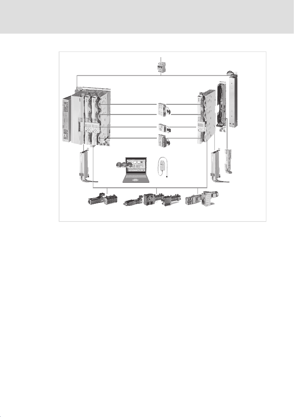
1.1.3 System overview
The following figure shows the most important components for the implementation of a
drive system with the Servo Drives 9400 product range.
On the way from the mains connection to the motor, you can see the basic principle of a
drive system on the left path. On the right path, the basic principle of a single−axis drive is
described.
10
In accordance with the requirements of your drive solution, your drive system can be
equipped or extended with specially adapted components.
EDS94SPP101 EN 10.2
Page 11
Preface
The 9400 Servo Drives product range
System overview
1
0
1
8
567
9
:
;
>?
=
@./
Mains voltage 3/PE AC 180 ... 528 V ±0 % or 3/PE AC 340 ... 528 V ±0 %
(depending on the device size/device power)
Mains fusing (not contained in the delivery programme)
Single Drives 9400 31
and corresponding installation backplanes
Mains filter for Single Drives 9400 537
RFI filter for Single Drives 9400 566
Multi Drives 9400 165
and corresponding installation backplanes
Power supply modules 9400
238, 285
(for DC bus installations with Multi Drives 9400)
Mains filter for power supply modules 9400 544
RFI filter for power supply modules 9400 584
2
3
4
<
=
SSP94SYS01
EDS94SPP101 EN 10.2
Equipment for all axis modules (device−dependent options):
Communication modules and extension modules 368
Memory modules 416
Safety modules 424
Motor holding brake control modules 444
Brake resistors 620
Diagnostic adapters 502
L−force Engineer (software)
Servo motors
Geared servo motors ( " )
Standard geared motors ( " )
Motor cables/system cables
(manual "System cables")
(motor catalogue)
11
Page 12

1
1.2 About this Hardware Manual
1.2.1 Information provided by the Hardware Manual
Preface
About this Hardware Manual
Information provided by the Hardware Manual
Target group
This Hardware Manual is intended for all persons who install, commission, and adjust 9400
servo controllers.
Together with the catalog it forms the basis of project planning for the manufacturers of
machines and plants.
Contents
This Hardware Manual is meant as an addition to the Mounting Instructions included in
the scope of supply:
ƒ The features and functions are described in detail.
ƒ It provides detailed information on additional ranges of application.
How to find information
Each chapter forms a complete unit and informs you about an individual subject:
ƒ You therefore only have to read the chapter containing the information you need.
ƒ The Table of Contents and Index help you to find all information about a certain
topic.
ƒ Descriptions and data of other Lenze products (drive PLC, Lenze geared motors,
Lenze motors, ...) can be found in the corresponding catalogs, Operating Instructions
and Manuals. The required documentation can be ordered at your Lenze sales
partner or downloaded as PDF file from the Internet.
Tip!
Information and tools concerning the Lenze products can be found in the
download area at
www.lenze.com
12
EDS94SPP101 EN 10.2
Page 13

Preface
About this Hardware Manual
Products to which the Hardware Manual applies
1
1.2.2 Products to which the Hardware Manual applies
Power modules
1 2 3 4 5 6 7 8 9 10 11 12 13 14 15 16 17 18 19
E94 x x x E xxx x x xx xx xx −
Type / product range
9400 Servo Drives
Version
A = 1.
B = 2.
N = not relevant
Version
S = single−axis controller (Single Drive)
M = multi−axis controller (Multi Drive)
P = power supply module
R = regenerative power supply module
Variant
H = HighLine
N = not relevant
P = PLC
Mechanical version
E = Installation
Rated current (rounded)
e.g. 007 = 7 A, 024 = 23.5 A
Voltage class
2 = 230 V ~ / 300 V =
4 = 400 V ~ / 540 V =
Safety module in MSI (place 7 of the extension modules)
A ... F
Memory module in MMI (places 7 and 8 of the extension modules)
22 ... 44
Extension module in MXI2 (places 7 and 8 of the extension modules)
xx
Extension module in MXI1 (places 7 and 8 of the extension modules)
xx
In the case of complete devices, the type code can contain a 5−place item of information regarding the configured
installation backplane, whereby this information appears at place 19 after the separator (see places 7 to 14,
power−related accessories).
In addition, a 6−place item of information regarding an integrated motor holding brake control module can be
contained (see places 6 to 14, performance−related accessories. "N" means "Not relevant".
With the help of the type code, you can identify supplied products on the basis of the information on the nameplate.
In the product catalogue, you can find the possible configuration in order to order the product.
EDS94SPP101 EN 10.2
13
Page 14

1
Preface
About this Hardware Manual
Products to which the Hardware Manual applies
Extension modules
1 2 3 4 5 6 7 8
E94 x Y x xx
Type / product range
9400 Servo Drives
Version
A = 1.
N = not relevant
Identification
Y = module
Module group
C = communication
F = feedback
M = memory
A = safety
Module identification
communication
CA = CANopen®
DN = DeviceNet
EN = Ethernet 2 port
EO = EtherNet/IP
EP = POWERLINK
EC = POWERLINK CN
ET = EtherCAT®
PM = PROFIBUS®
ER = PROFINET®
IB = INTERBUS
Feedback
LF = digital frequency
Memory
22 = Memory module MM220 with MC HighLevel licence
33 = Memory module MM330 with MC TopLevel licence
34 = Memory module MM340 with PLC licence
43 = Memory module MMx20 with MC TopLevel licence
44 = Memory module MMx40 with PLC licence
Safety
A = SM0 safety module
B = SM100 safety module
E = SM301safety module
F = SM302 safety module
14
EDS94SPP101 EN 10.2
Page 15

Power−related accessories
Type / product range
9400 Servo Drives
Version
Identification
Z = accessories
Component class 1
H = brake control
P = mounting backplane
M = mains filter
R = RFI filter
Preface
About this Hardware Manual
Products to which the Hardware Manual applies
1 2 3 4 5 6 7 9 10 11 14
E94 A Z x x xxx x
1
Component class 2
M = multiple axes
P = power supply module
R = regenerative module
S = single axis
X,Y = type
N = not specified
Rated current (rounded)
e.g.
008 = 8 A
024 = 23.5 A
...
Voltage class
1 = 24 V =
2 = 230 V ~ / 300 V =
4 = 400 V ~ / 540 V =
EDS94SPP101 EN 10.2
15
Page 16

1
Preface
About this Hardware Manual
Products to which the Hardware Manual applies
Power−independent accessories
1 2 3 4 5 6 7 8 9
E94 A Z x xxx
Type / product range
9400 Servo Drives
Version
Identification
Z = accessories
Accessory group
J = mechanical components, other
S = software
K = keypad
N = not specified
Module identification
16
EDS94SPP101 EN 10.2
Page 17

1.3 Document history
Material number Version Description
.W@D 10.2 02/2018 TD29 Correction of device features
13543133 10.1 01/2018 TD29 Information on UL fuses added
13543135 10.0 12/2017 TD29 General corrections and standardisation
13514043 9.0 11/2016 TD29 New devices inserted; old devices removed
13480643 8.0 09/2015 TD15 Additions: Conformity with EAC
13344991 7.1 07/2010 TD29 Additions, corrections
13344991 7.0 07/2010 TD29 Additions, corrections
13320181 6.0 11/2009 TD15 Additions, corrections
13280002 5.0 11/2008 TD15 Additions, corrections
13261288 4.2 07/2008 TD15 Additions, corrections
13256547 4.1 06/2008 TD15 Additions, corrections
13225695 4.0 04/2007 TD15 Additions, corrections
13192254 3.1 03/2007 TD15 Additions, corrections
13192254 3.0 02/2007 TD15 Additions, corrections
13095102 2.0 09/2006 TD15 Additions, corrections (field test)
13095102 1.0 12/2005 TD15 First edition (field test)
Preface
Document history
New UL specifications in preparation
Corrections
Corrections
Document structure updated
1
EDS94SPP101 EN 10.2
17
Page 18

1
Preface
Conventions used
1.4 Conventions used
This documentation uses the following conventions to distinguish between different
types of information:
Spelling of numbers
Decimal separator
Warnings
UL warnings
UR warnings
Text
Program name » « PC software
Icons
Page reference Reference to another page with additional
Documentation reference Reference to another documentation with
Point In general, the decimal point is used.
For instance: 1234.56
Given in English and French
For example: »Engineer«, »Global Drive
Control« (GDC)
information
For instance: 16 = see page 16
additional information
For example: EDKxxx = see
documentation EDKxxx
18
EDS94SPP101 EN 10.2
Page 19

1.5 Notes used
The following pictographs and signal words are used in this documentation to indicate
dangers and important information:
Safety instructions
Structure of safety instructions:
Danger!
(characterises the type and severity of danger)
Note
(describes the danger and gives information about how to prevent dangerous
situations)
Pictograph and signal word Meaning
Danger!
Danger!
Stop!
Preface
Notes used
Danger of personal injury through dangerous electrical voltage.
Reference to an imminent danger that may result in death or
serious personal injury if the corresponding measures are not
taken.
Danger of personal injury through a general source of danger.
Reference to an imminent danger that may result in death or
serious personal injury if the corresponding measures are not
taken.
Danger of property damage.
Reference to a possible danger that may result in property
damage if the corresponding measures are not taken.
1
Application notes
Pictograph and signal word Meaning
Note!
Tip!
Special safety instructions and application notes
Pictograph and signal word Meaning
Warnings!
Warnings!
Important note to ensure troublefree operation
Useful tip for simple handling
Reference to another documentation
Safety note or application note for the operation according to
UL or CSA requirements.
The measures are required to meet the requirements according
to UL or CSA.
EDS94SPP101 EN 10.2
19
Page 20

1
Preface
Legal regulations
1.6 Legal regulations
Labelling
Lenze drive controllers are clearly labelled and defined by the contents of the nameplate.
Manufacturer
Lenze Automation GmbH, Postfach 10 13 52, 31763 Hameln, Hans−Lenze−Str. 1, 31855
Aerzen
CE conformity
Complies with the "Low voltage" EC Directive
Application as directed
The following applies to 9400 servo controllers and the accessories:
ƒ They must only be operated under the operating conditions described in this
Hardware Manual.
ƒ They are components for open and closed loop control of control variable speed
drives with asynchronous standard motors, asynchronous servo motors, PM
synchronous servo motors.
ƒ They are components for installation into a machine.
ƒ They are components used for assembly together with other components to form a
machine.
ƒ They comply with the protection requirements of the "Low Voltage" EC Directive.
ƒ They are not machines for the purposes of the "EC "Machinery" Directive.
ƒ They are not to be used as household appliances but for industrial purposes only.
The following applies to drives with 9400 servo controllers:
ƒ They comply with the EC "Electromagnetic Compatibility" Directive if they are
installed according to the guidelines of CE−typical drive systems.
ƒ They can be used for operation at public and non−public mains.
ƒ They can be used in industrial premises as well as residential and commercial
premises.
ƒ The user is responsible for the compliance of his application with the EC Directives.
Any other use shall be deemed inappropriate!
20
EDS94SPP101 EN 10.2
Page 21

Preface
Legal regulations
Liability
The information, data, and notes in this Hardware Manual met the state of the art at the
time of printing. Claims referring to drive systems which have already been supplied
cannot be derived from the information, illustrations, and descriptions given in this
Manual.
The specifications, processes, and circuitry described in this Hardware Manual are for
guidance only and must be adapted to your own application. Lenze does not take any
responsibility for the suitability of the process and circuit proposals.
The specifications in this Hardware Manual describe the product features without
guaranteeing them.
Lenze does not accept any liability for damage and failures caused by:
ƒ Disregarding the Hardware Manual
ƒ Unauthorised modifications to the controller
ƒ Operating errors
1
ƒ Improper working on and with the controller
Warranty
See Terms of sale and delivery.
Warranty claims must be made to your Lenze representative immediately after detecting
the deficiency or fault.
The warranty is void in all cases where liability claims cannot be made.
EDS94SPP101 EN 10.2
21
Page 22

1
Preface
Terms and abbreviations used
1.7 Terms and abbreviations used
Controller Any frequency inverter, servo inverter, or DC speed controller
Axis, drive Lenze controller combined with a motor or geared motor and other
Basic insulation Insulation for the basic protection against dangerous shock currents
Functional insulation Insulation for perfect operation
Double insulation Basic insulation and additional insulation
Reinforced insulation Standardised insulating system, equivalent protection to double
Cxxxxx/y Subcode y of code Cxxxx
Xk/y Terminal y on terminal strip Xk (e.g. X3/28 = terminal 28 on terminal
Cross−reference to a chapter with the corresponding page number
AC AC current or AC voltage
DC DC current or DC voltage
U
[V]
LN
U
[V]
DC
[V]
U
M
Lenze drive components
insulation
(e.g. C0410/3 = subcode 3 of code C0410)
strip X3)
Rated mains voltage
DC voltage
Output voltage/voltage across the motor terminals
[A]
I
LN
I
[A]
aN
[A]
I
aM
I
[mA]
PE
[A]
I
DC
P
[kW]
N
[W]
P
V
P
[kW]
DC
[kVA]
S
N
[Nm]
M
N
f
[Hz]
max
L [mH] Inductance
R [] Resistance
DIN Deutsches Institut für Normung
Rated mains current
Rated output current
Maximum output current
Discharge current
Direct current, r.m.s. value from direct current and harmonic currents,
for the dimensioning of DC−bus cables and DC−bus fuses
Rated motor power
Inverter power loss
Power on the DC voltage side
Apparent output power of controller
Rated torque
Maximum frequency
22
EDS94SPP101 EN 10.2
Page 23

Preface
Terms and abbreviations used
EMC Electromagnetic compatibility
EN European standard
IEC International Electrotechnical Commission
IP International Protection Code
NEMA National Electrical Manufacturers Association
VDE Verband deutscher Elektrotechniker
CE Communauté Européene
UL Underwriters Laboratories
1
EDS94SPP101 EN 10.2
23
Page 24

2
Safety instructions
General safety and application notes for Lenze controllers
2 Safety instructions
2.1 General safety and application notes for Lenze controllers
(in accordance with Low−Voltage Directive 2014/35/EU)
For your pesonal safety
Disregarding the following basic safety measures may lead to severe personal injury and
damage to material assets:
ƒ Only use the product as directed.
ƒ Never commission the product in the event of visible damage.
ƒ Never commission the product before assembly has been completed.
ƒ Do not carry out any technical changes on the product.
ƒ Only use the accessories approved for the product.
ƒ Only use original spare parts from Lenze.
ƒ Observe all regulations for the prevention of accidents, directives and laws
applicable on site.
ƒ Transport, installation, commissioning and maintenance work must only be carried
out by qualified personnel.
– IEC 364 and CENELEC HD 384 or DIN VDE 0100 and IEC−Report 664 or
DIN VDE 0110 and national regulations for the prevention of accidents must be
observed.
– According to the basic safety information, qualified, skilled personnel are persons
who are familiar with the assembly, installation, commissioning, and operation of
the product and who have the qualifications necessary for their occupation.
ƒ Observe all specifications in this documentation.
– This is the condition for safe and trouble−free operation and the achievement of
the specified product features.
– The procedural notes and circuit details described in this documentation are only
proposals. It’s up to the user to check whether they can be transferred to the
particular applications. Lenze Automation GmbH does not accept any liability for
the suitability of the procedures and circuit proposals described.
24
ƒ According to their enclosure, Lenze controllers (frequency inverters, servo inverters,
DC speed controllers) and their components can carry a voltage, or parts of the
controllers can move or rotate during operation. Surfaces can be hot.
– Non−authorised removal of the required cover, inappropriate use, incorrect
installation or operation create the risk of severe injury to persons or damage to
material assets.
– For more information, please see the documentation.
ƒ There is a high amount of energy within the controller. Therefore always wear
personal protective equipment (body protection, headgear, eye protection, ear
protection, hand guard) when working on the controller when it is live.
EDS94SPP101 EN 10.2
Page 25

Safety instructions
General safety and application notes for Lenze controllers
Intended use
Drive controllers are components designed for the installation in electrical systems or
machinery. They must not be used as household appliances. They are intended exclusively
professional and commercial purposes according to EN 61000−3−2.
When controllers are installed into machines, commissioning (i.e. starting of the operation
as directed) is prohibited until it is proven that the machine complies with the regulations
of the EC Directive 2006/42/EC (Machinery Directive); EN 60204 must be observed.
Commissioning (i.e. starting of the operation as directed) is only allowed when there is
compliance with the EMC Directive (2014/30/EU).
The inverters meet the requirements of the Low−Voltage Directive 2014/35/EU. The
harmonised standard EN 61800−5−1 applies to the inverters.
The technical data and supply conditions can be obtained from the nameplate and the
documentation. They must be strictly observed.
The actuation of the inverters in specific areas in compliance with EN61800−3 (EMC
categories) possibly requires the use of filters.
Warning: in residential environments, this product may cause high−frequency
interferences which may make the implementation of interference suppression measures
necessary.
2
Transport, storage
Please observe the notes on transport, storage, and appropriate handling.
Observe the climatic conditions according to the technical data.
Installation
The controllers must be installed and cooled according to the instructions given in the
corresponding documentation.
The ambient air must not exceed degree of pollution 2 according to EN 61800−5−1.
Ensure proper handling and avoid mechanical stress. Do not bend any components and do
not change any insulation distances during transport or handling. Do not touch any
electronic components or contacts.
Controllers contain electrostatically sensitive components which can easily be damaged
by inappropriate handling. Do not damage or destroy any electrical component since doing
so might endanger your health!
EDS94SPP101 EN 10.2
25
Page 26

2
Safety instructions
General safety and application notes for Lenze controllers
Electrical connection
When working on live inverters, observe the applicable national regulations for the
prevention of accidents.
Carry out the electrical installation according to the relevant regulations (e. g. cable
cross−sections, fusing, connection to the PE conductor). Additional notes are included in
the documentation.
This documentation contains information on installation in compliance with EMC
(shielding, earthing, filter, and cables). These notes must also be observed for CE−marked
controllers. The manufacturer of the system is responsible for compliance with the limit
values demanded by EMC legislation. The controllers must be installed in housings (e.g.
control cabinets) to meet the limit values for radio interferences valid at the site of
installation. The housings must enable an EMC−compliant installation. Observe in
particular that e.g. the control cabinet doors have a circumferential metal connection to
the housing. Reduce housing openings and cutouts to a minimum.
Lenze controllers may cause a DC current in the PE conductor. If a residual current device
(RCD) is used for protection against direct or indirect contact for a controller with
three−phase supply, only a residual current device (RCD) of type B is permissible on the
supply side of the controller. If the controller has a single−phase supply, a residual current
device (RCD) of type A is also permissible. Apart from using a residual current device (RCD),
other protective measures can be taken as well, e.g. electrical isolation by double or
reinforced insulation or isolation from the supply system by means of a transformer.
Operation
If necessary, systems including controllers must be equipped with additional monitoring
and protection devices according to the valid safety regulations (e.g. law on technical
equipment, regulations for the prevention of accidents). You are allowed to adapt the
controllers to your application. Please observe the corresponding information given in the
documentation.
After the controller has been disconnected from the supply voltage, all live components
and power terminals must not be touched immediately because capacitors can still be
charged. Please observe the corresponding stickers on the controller.
Keep all protective covers and doors closed during operation.
Safety functions
Certain controller versions support safety functions (e.g. "Safe torque off", formerly "Safe
standstill") according to the requirements of the EC Directive 2006/42/EC (Machinery
Directive). The notes on the integrated safety system provided in this documentation must
be observed.
Maintenance and servicing
The controllers do not require any maintenance if the prescribed conditions of operation
are observed.
26
Waste disposal
Recycle metal and plastic materials. Assembled PCBs must be disposed of professionally.
The product−specific safety and application notes given in these instructions must be
observed!
EDS94SPP101 EN 10.2
Page 27

Safety instructions
General safety and application notes for Lenze motors
2.2 General safety and application notes for Lenze motors
(according to Low−Voltage Directive 2014/35/EU)
General
Low−voltage machines have dangerous, live and rotating parts as well as possibly hot
surfaces.
Synchronous machines induce voltages at open terminals during operation.
All operations serving transport, connection, commissioning and maintenance are to be
carried out by skilled, responsible technical personnel (observe EN 50110−1 (VDE 0105−1)
and IEC 60364). Improper handling can cause severe injuries or damages.
Lowvoltage machines may only be operated under the conditions that are indicated in the
section "Application as directed".
The conditions at the place of installation must comply with the data given on the
nameplate and in the documentation.
2
Application as directed
Lowvoltage machines are intended for commercial installations. They comply with the
harmonised standards of the series IEC/EN60034 (VDE 0530). Their use in potentially
explosive atmospheres is prohibited unless they are expressly intended for such use
(follow additional instructions).
Lowvoltage machines are components for installation into machines as defined in the
Machinery Directive 2006/42/EC. Commissioning is prohibited until the conformity of the
end product with this directive has been established (follow i. a. EN 60204−1).
Lowvoltage machines with IP23 protection or less are only intended for outdoor use when
applying special protective features.
The integrated brakes must not be used as safety brakes. It cannot be ruled out that factors
which cannot be influenced, such as oil ingress due to a defective Aside shaft seal, cause
a brake torque reduction.
Transport, storage
Damages must be reported immediately upon receipt to the forwarder; if required,
commissioning must be excluded. Tighten screwedin ring bolts before transport. They are
designed for the weight of the lowvoltage machines, do not apply extra loads. If necessary,
use suitable and adequately dimensioned means of transport (e. g. rope guides).
Remove transport locking devices before commissioning. Reuse them for further
transport. When storing low−voltage machines, ensure a dry, dustfree and low−vibration
(v
0.2 mm/s) environment (bearing damage while being stored).
eff
EDS94SPP101 EN 10.2
27
Page 28

2
Safety instructions
General safety and application notes for Lenze motors
Installation
Ensure an even surface, solid foot/flange mounting and exact alignment if a direct clutch
is connected. Avoid resonances with the rotational frequency and double mains frequency
which may be caused by the assembly. Turn rotor by hand, listen for unusual slipping
noises. Check the direction of rotation when the clutch is not active (observe section
"Electrical connection").
Use appropriate means to mount or remove belt pulleys and clutches (heating) and cover
them with a touch guard. Avoid impermissible belt tensions.
The machines are halfkey balanced. The clutch must be halfkey balanced, too. The visible
jutting out part of the key must be removed.
If required, provide pipe connections. Designs with shaft end at bottom must be protected
with a cover which prevents the ingress of foreign particles into the fan. Free circulation of
the cooling air must be ensured. The exhaust air also the exhaust air of other machines
next to the drive system must not be taken in immediately.
Electrical connection
All operations must only be carried out by qualified and skilled personnel on the
lowvoltage machine at standstill and deenergised and provided with a safe guard to
prevent an unintentional restart.This also applies to auxiliary circuits (e. g. brake, encoder,
blower).
Check safe isolation from supply!
If the tolerances specified in EN 600341; IEC 34 (VDE 05301) voltage ±5 %, frequency ±2 %,
waveform, symmetry are exceeded, more heat will be generated and the electromagnetic
compatibility will be affected.
Observe the data on the nameplate, operating notes, and the connection diagram in the
terminal box.
The connection must ensure a continuous and safe electrical supply (no loose wire ends);
use appropriate cable terminals. The connection to the PE conductor must be safe. The
plug−in connectors must be bolt tightly (tostop).
The clearances between blank, live parts and to earth must not fall below 8 mm at
V
550 V, 10 mm at V
rated
The terminal box must be free of foreign particles, dirt and moisture. All unused cable
entries and the box itself must be sealed against dust and water.
725 V, 14 mm at V
rated
rated
1000 V.
28
EDS94SPP101 EN 10.2
Page 29

Safety instructions
General safety and application notes for Lenze motors
Commissioning and operation
Before commissioning after longer storage periods, measure insulation resistance. In case
of values 1 k per volt of rated voltage, dry winding.
For trial run without output elements, lock the featherkey. Do not deactivate the
protective devices, not even in a trial run.
Check the correct operation of the brake before commissioning lowvoltage machines with
brakes.
Integrated thermal detectors do not provide full protection for the machine. If necessary,
limit the maximum current. Parameterise the controller so that the motor will be switched
off with I > I
Vibrational severities v
acceptable if the clutch is activated.
If deviations from normal operation occur, e.g. increased temperatures, noises, vibrations,
find the cause and, if required, contact the manufacturer. In case of doubt, switch off the
lowvoltage machine.
after a few seconds of operation, especially at the risk of blocking.
rated
3.5 mm/s (P
eff
15 kW) or 4.5 mm/s (P
rated
rated
> 15 kW) are
2
If the machine is exposed to dirt, clean the air paths regularly.
Shaft sealing rings and roller bearings have a limited service life.
Regrease bearings with relubricating devices while the lowvoltage machine is running.
Only use the grease recommended by the manufacturer. If the grease drain holes are
sealed with a plug, (IP54 drive end; IP23 drive and nondrive end), remove plug before
commissioning. Seal bore holes with grease. Replace prelubricated bearings (2Z bearing)
after approx. 10,000 h 20,000 h, at the latest however after 3 4 years.
The product−specific safety and application notes given in these instructions must be
observed!!
EDS94SPP101 EN 10.2
29
Page 30

2
Safety instructions
Residual hazards
2.3 Residual hazards
Protection of persons
ƒ Before working on the controller, check if no voltage is applied to the power
terminals because
– because the power terminals U, V, W, +UG, −UG, Rb1 and Rb2 carry hazardous
voltages for up to 30 minutes after power−off depending on the device.
– the power terminals L1, L2, L3; U, V, W, +UG, −UG, Rb1 and Rb2 carry hazardous
voltages when the motor is stopped.
Device protection
ƒ Plug on or pull off all pluggable terminals only in deenergised condition!
ƒ Detach the controllers only in deenergised conditions from their installation
backplanes or the back panel of the control cabinet!
ƒ Cyclic switching on and off of the mains voltage can overload and destroy the input
current limitation of the controller:
– Cyclic mains switching of 5−times in 5 minutes is permissible without restrictions.
Motor protection
ƒ Depending on the controller settings, the connected motor can be overheated by:
– For instance, longer DC−braking operations.
– Longer operation of self−ventilated motors at low speed.
Protection of the machine/system
ƒ Drives can reach dangerous overspeeds (e.g. setting of high output frequencies in
connection with motors and machines unsuitable for such conditions):
– The controllers do not offer any protection against such operating conditions. Use
additional components for this purpose.
30
EDS94SPP101 EN 10.2
Page 31

3 Single−axis controllers
3.1 Device features
ƒ Space−saving installation by compact design
ƒ Innovative installation concept
ƒ Power range: 370 W to 240 kW
ƒ Pluggable and same connection system for the control cables in the entire power
range
ƒ Direct AC mains connection for "Single Drive" design
ƒ DC link busbar (DC−bus) integrated or can be retrofitted
(devices up to 24 A/11 kW)
ƒ Integrated brake chopper
Single−axis controllers
Device features
3
ƒ Direct connection of resolver or encoder feedback
– Easy connection via predesigned system cable (accessories)
ƒ Integrated phase controller for drift−free standstill
ƒ Field−oriented control for asynchronous and synchronous motors
ƒ Digital synchronisation system via bus system or
digital frequency (extension module required)
ƒ User configuration for control functions and input/output signals
– Comprehensive library with function blocks
– High flexibility with regard to the adaptation of the internal control structure to
the drive task
ƒ Extension interfaces for
– communication
– Controller functionality
– Safety system
ƒ System bus (CANopen)
– servo inverter connection
– for extending input and output terminals
– connecting keypad and display units (HMI)
EDS94SPP101 EN 10.2
31
Page 32

3
Single−axis controllers
Overview of the devices
3.2 Overview of the devices
Note!
For reasons of clarity, device types in this manual are placed together in groups
with shared device characteristics. For example:
ƒ "Devices in the range 2 ... 24 A (0.37 ... 11 kW)" (often from project planner’s
viewpoint) or
ƒ "Device sizes 1, 2 and 3" (often from installation point of view)
The following table gives you an overview of the different device characteristics:
Type Rated current (rounded) Motor power (typ.) Device size (DS)
E94ASxE0024
E94ASxE0034
E94ASxE0044
E94ASxE0074
E94ASxE0134
E94ASxE0174
E94ASxE0244
E94ASxE0324
E94ASxE0474
E94ASxE0594
E94ASxE0864
E94ASxE1044
E94BSxE1454 145 A 75 kW 81
E94BSxE1724
E94BSxE2024
E94BSxE2454
E94BSxE2924 292 A 150 kW 83
E94BSxE3664
E94BSxE4604
2 A
3 A
4 A
7 A
13 A
17 A
24 A
32 A
47 A
59 A
86 A
104 A
172 A
202 A
245 A
366 A
460 A
0.37 kW
0.75 kW
1.5 kW
3.0 kW
5.5 kW
7.5 kW
11 kW
15 kW
22 kW
30 kW
45 kW
55 kW
90 kW
105 kW
130 kW
190 kW
240 kW
1
2
3
6
7
82
91
32
EDS94SPP101 EN 10.2
Page 33

General data and operating conditions
3.3 General data and operating conditions
General data
Conformity and approval
Conformity
CE
CE 2014/30/EU EMC Directive
EAC TPTC004/2011
EAC TPTC020/2011
Approval
E94ASxE0024 (0.37 kW) ... E94ASxE1044 (55 kW):
CULUS
E94BSxE1454 (145 A, 75 kW) ... E94BSxE2024 (202 A, 105 kW),
E94BSxE3664 (366 A, 190 kW) ... E94BSxE4604 (460 A, 240 kW):
CULUS
E94BSxE2454 (245 A, 130 kW) ... E94BSxE2924 (292 A, 150 kW):
In preparation
2014/35/EU Low−Voltage Directive
(TPZU004/2011)
(TPZU020/2011)
UL61800−5−1 Industrial Control Equipment
CSA C22.2 No. 274−13 Industrial Control Equipment
UL 508C Industrial Control Equipment
CSA C22.2 No. 274−13 Industrial Control Equipment
Single−axis controllers
Regarding the safety of
low−voltage equipment
Electromagnetic
compatibility of technical
products
(File No. E132659) for USA
(File No. E132659) for Canada
(File No. E132659) for USA
(File No. E132659) for Canada
3
Eurasian conformity
TR ZU: Technical regulation of
the tariff union
Eurasian conformity
TR ZU: Technical regulation of
the tariff union
EDS94SPP101 EN 10.2
33
Page 34

3
Single−axis controllers
General data and operating conditions
Protection of persons and device protection
Type of protection
Insulation resistance EN 61800−5−1 Overvoltage category III
Control circuit isolation EN 61800−5−1 up to 2000 m amsl:
Short−circuit strength EN 61800−5−1 Motor connection: with restrictions, error acknowledgement
Motor − protective
measures against
Leakage current EN 61800−5−1 > 3.5 mA AC, > 10 mA DC Observe regulations and
Cyclic mains switching Cyclic mains switching of 5 times in 5 minutes is permissible
EN 60529 IP 20
NEMA 250 Protection against accidental
contact in accordance with
type 1
from 2000 m amsl: external measures for compliance with
the overvoltage category II are required, e.g.
upstream connection of transformer
upstream connection of overvoltage protection system
Safe mains isolation by double/reinforced insulation for
mains with neutral earthing with a rated voltage for the
external conductor/star point up to 300 V.
from 2000 m amsl:
If an overvoltage protection system is connected upstream to
the device, additional external measures are required for
maintaining the safe isolation.
required
Control terminals: full
Short circuit
Earth fault
Overvoltage
motor stalling
Motor overtemperature
(PTC or thermal contact, I
without restrictions.
Outside the wire range of
the terminals on the
motor side
2
t monitoring)
safety instructions!
Design
Housing
Carrier housing
Carrier housing Device sizes
Dimensions see "Mechanical installation"
Weight see "Mechanical installation"
Mounting conditions
Mounting place
Mounting position vertical
Clearance
above/beneath
at the side
Device sizes
1, 2 and 3
as of 6
Glass−fiber reinforced plastic
Metal
in the control cabinet
Comply with the device−relating mounting instructions.
Can be installed in a row without any clearance
34
EDS94SPP101 EN 10.2
Page 35

Single−axis controllers
General data and operating conditions
Supply conditions "Single Drive"
AC mains operation Device size 1 ... 7: Direct connection
Device size 81 ... 91: Direct connection via terminals with
wire end ferrules; alternatively via ring cable lugs
DC−bus operation Device size 1 ... 7: Direct connection via terminals or busbar
Power systems
TT
TN
IT Up to device size 83: additional measure necessary inside
Motors EN 60034 Only use motors that are suitable for inverter operation.
Operating conditions
system (retrofittable)
Device size 81 ... 91: Direct connection via terminals with
wire end ferrules; alternatively via ring cable lugs
For more information, please see the chapter DC−bus
operation.
Operation allowed without restrictions.
device (see "Earthing of internal EMC filter", 108)
device size 91: Specify when ordering
Insulation strength: max. û 1.5 kV, max. du/dt 5 kV/s
3
Environmental conditions
Climate
Storage
Transport IEC/EN 60721−3−2 Device size 1 ... 6: 2K3 (−25 ... +70 °C)
Operation IEC/EN 60721−3−3 3K3 (−10 ... +55 °C)
Site altitude 0 ... 4000 m amsl
Pollution EN 61800−5−1 Degree of pollution 2
Vibration resistance (9.81 m/s
Transport
(only tested for device
size 1 ... 7)
Operation
IEC/EN 60721−3−1 1K3 (−25 ... +60 °C)
Current derating at +45 ... +55 °C:
Device size 1 ... 7: 2.5 %/°C
Device size 81 ... 91: 1 %/°C
Device size 1 ... 7 with 1000 ... 4000 m amsl: Current derating
5 %/1000 m
Device size 81 ... 91 with 1000 ... 4000 m amsl: Current
derating 10 %/1000 m
2
= 1 g)
IEC/EN 60721−3−2 2M2
EN 61800−2
Germanischer Lloyd 5 ... 13.2 Hz: Amplitude ±1 mm
IEC/EN 60068−2−6
2 ... 9 Hz: Amplitude 3.5 mm
10 ... 200 Hz: acceleration resistant up to 10 m/s
200 ... 500 Hz: acceleration resistant up to 15 m/s
13.2 ... 100 Hz: acceleration resistant up to 0.7 g
Device size 81 ... 83: Mounting must be executed with
vibration dampers by the customer. Please consult Lenze.
Device size 91: The control cabinet has to be
vibration−damped.
10 ... 57 Hz: Amplitude 0.075 mm
57 ... 150 Hz: Acceleration resistant up to 1 g
2
2
EDS94SPP101 EN 10.2
35
Page 36

3
Single−axis controllers
General data and operating conditions
General electrical data
Assignment
Axis module Installation
E94ASxE0024
E94ASxE0034
E94ASxE0044
E94ASxE0074
E94ASxE0134
E94ASxE0174
E94ASxE0244
Requirements on the motor cable
Capacitance per unit length
2.5 mm
4 mm2/AWG 12 C
Electric strength
Maximum motor and feedback cable lengths
(for shielded motor cable with rated mains voltage)
If EMC conditions must be met, the permissible cable lengths can be reduced.
Type Device size [m]
E94ASxE0024
E94ASxE0034
E94ASxE0044
E94ASxE0074
E94ASxE0134
E94ASxE0174
E94ASxE0244
E94ASxE0324
E94ASxE0474
E94ASxE0594
E94ASxE0864
E94ASxE1044
E94BSxE1454 81 150 (100 1))
E94BSxE1724
E94BSxE2024
E94BSxE2454
E94BSxE2924 83 150 (100 1))
E94BSxE3664
E94BSxE4604
Tab. 3−1
1)
If safety functions with SM301/SM302, which require reliable speed and position detection, are used.
backplane
E94AZPS0034
E94AZPS0074 2 E94AZJA007: 40 A, 700 V DC / EFSAR0040ARHN
E94AZPS0244 3 E94AZJA024: 100 A, 700 V DC / EFSAR0100ARZN
2
/AWG 14 C
VDE 0250−1 U0/U
UL U 600 V
1
2 100
3 100
6 100
7 100
82 150 (100 1))
91 150 (100 1))
Device size Accessories: busbar mounting set/spare fuse
1 E94AZJA003: 16 A, 700 V DC / EFSAR0016ARHN
Core/core/CCore/shield
Core/core/CCore/shield
0.6/1.0 kV
=
(U0 = r.m.s. value external − conductor/PE,
U = r.m.s. value − external conductor/external conductor)
(U = r.m.s. value external conductor/external conductor)
< 75/150 pF/m
< 150/300 pF/m
50
36
EDS94SPP101 EN 10.2
Page 37

Single−axis controllers
General data and operating conditions
Max. shielded motor cable lengths for compliance with the
conducted interference emission according to C1/C2
Type with RFI filter with mains filter without filter
E94ASxE0024
E94ASxE0034
E94ASxE0044
E94ASxE0074
E94ASxE0134
E94ASxE0174
E94ASxE0244
E94AZRS0044
−/50 m
E94AZRS0104
−/50 m
E94AZRS0294
−/50 m
1)
E94AZMS0034
25 m/50 m −/10 m
1)
E94AZMS0094
25 m/100 m −/10 m
E94AZMS0184
1)
25 m/100 m −/10 m
E94AZMS0314
25 m/100 m −/10 m
E94ASxE0324
E94ASxE0474
E94ASxE0594
E94ASxE0864
E94ASxE1044
E94AZRS0544
50 m/100 m
E94AZRS0954
50 m/100 m
2)
2)
Tab. 3−2
EMC limit value class for conducted noise emission in TN/TT systems:
C2 to EN 61800−3 corresponds to class A to EN 55011
C1 to EN 61800−3 corresponds to class B to EN 55011
1)
Universal−current−sensitive earth−leakage circuit breaker 30 mA
If several devices or cable lengths 50 m are used, it is possible that the circuit breaker will respond, depending on
the type of cable and the switching frequency.
2)
Universal−current−sensitive earth−leakage circuit breaker 300 mA
If several devices or cable lengths > 50 m are used, it is possible that the circuit breaker will respond, depending on
the type of cable and the switching frequency.
3)
Universal−current−sensitive earth−leakage circuit breaker, cable length 25 m: 30 mA, cable length > 25 m: 300 mA,
If several devices or cable lengths 50 m are used, it is possible that the circuit breaker will respond, depending on
the type of cable and the switching frequency.
4)
See chapter "Fuses and cable cross−sections", ( 61).
3)
4)
3)
4)
3)
4)
3)
4)
−
−
−/50 m
−/50 m
4)
4)
3
Max. shielded motor cable lengths for compliance with the
conducted interference emission according to C2
Type with RFI filter with mains filter without filter
E94BSxE1454 E94AZRS1804
(3F480−180.290EM), 150 m
E94BSxE1724 E94AZRS1804
(3F480−180.290EM), 150 m
E94BSxE2024 E94AZRS3004
(3F480−300.290EM), 150 m
E94BSxE2454 E94AZRS3004
(3F480−300.290EM), 150 m
E94BSxE2924 E94AZRS3004
(3F480−300.290EM), 150 m
E94BSxE3664 E94AZRS4154
(3F480−415.290EM), 150 m
E94BSxE4604 E94AZRS4154
(3F480−415.290EM), 150 m
− −
− −
− −
− −
− −
− −
− −
EDS94SPP101 EN 10.2
37
Page 38

3
Single−axis controllers
General data and operating conditions
Max. shielded motor cable lengths for compliance with the
conducted interference emission according to C3
Type with RFI filter with mains filter without filter
E94BSxE1454 − − 150 m
E94BSxE1724 − − 150 m
E94BSxE2024 − − 150 m
E94BSxE2454 − − 150 m
E94BSxE2924 − − 150 m
E94BSxE3664 − − 150 m
E94BSxE4604 − − 150 m
Longer motor cables can be achieved when line filters are used in combination with
sinusoidal filters. Further conditions to be observed:
ƒ V/f control mode
ƒ Switching frequency is permanently set (C00018)
Max. motor cable lengths for compliance with the conducted interference emission according to C2 when
sinusoidal filters and line filters are used
Type
E94ASxE0024
E94ASxE0034
E94ASxE0044
E94ASxE0074
E94ASxE0134
E94ASxE0174
E94ASxE0244 − E94AZMS0314 EZS3−037A200
E94ASxE0324
E94ASxE0474 EZS3−061A200
E94ASxE0594 EZS3−072A200
E94ASxE0864
E94ASxE1044 EZS3−150A200
E94BSxE1454
E94BSxE1724
E94BSxE2024
E94BSxE2454
E94BSxE2924
E94BSxE3664
E94BSxE4604
Tab. 3−3
EMC limit classes of the conducted interference emission in TN/TT systems:
C2 according to EN 61800−3, corresponds to class A according to EN 55011
RFI filter Mains filter Sine filter shielded
−
−
− E94AZMS0184 EZS3−024A200
E94AZRS0544 −
E94AZRS0954 −
E94AZRS1804
3F480−180.290EM
E94AZRS1804
3F480−180.290EM
E94AZRS3004
3F480−300.290EM
E94AZRS3004
3F480−300.290EM
E94AZRS3004
3F480−300.290EM
E94AZRS4154
3F480−415.290EM
E94AZRS4154
3F480−415.290EM
E94AZMS0034 EZS3−004A200
E94AZMS0094 EZS3−010A200
EZS3−048A200
EZS3−115A200
− EZS3−180A200
− EZS3−250A200
− EZS3−250A200
− EZS3−350A200
− EZS3−350A200
− EZS3−480A200
−
EZS3−350A200
(2 in parallel)
unshielded
100 m
300 m
150 m
300 m
150 m
300 m
150 m
− m
Switching
frequency
4 kHz
or
8 kHz
4 kHz
or
8 kHz
2 kHz
or
4 kHz
2 kHz
or
4 kHz
38
EDS94SPP101 EN 10.2
Page 39

Single−axis controllers
General data and operating conditions
EMC
Operation on public supply
systems
Noise emission, in cables
Design
"Single Drive"
Design
"Multi Drive"
Noise immunity (to EN 61800−3)
Electrostatic discharge
(ESD)
Radio frequency
Cable−guided EN 61000−4−6 150 kHz ... 80 MHz, 10 V 80 % AM (1 kHz)
Interference (housing) EN 61000−4−3 80 MHz ... 1000 MHz, 10 V/m 80 % AM (1 kHz)
Burst
Power terminals and
interfaces
Signal interfaces EN 61000−4−4 1 kV/5 kHz
Control connections EN 61000−4−4 2 kV/5 kHz
Surge (surge voltage)
Power terminals EN 61000−4−5 1.2/50 s,
EN 61800−3
EN 61800−3 see Tab. 3−2 EMC protection requirements
EN 61000−4−2 8 kV with air discharge,
EN 61000−4−4 2 kV/5 kHz
The controllers are designed for use in an industrial
environment. Operation on public networks requires
measures to be taken for limiting the expected emission of
radio interferences.
Depending on the filter at the central DC supply module.
4 kV with contact discharge against housing
1 kV phase/phase, 2 kV phase/PE
3
EDS94SPP101 EN 10.2
39
Page 40

3
Single−axis controllers
General data and operating conditions
Protective insulation
Danger!
Dangerous electrical voltage
When one common voltage source is used for control voltages in separate
potential areas, the protective insulation between the separate potential areas
is deactivated.
Possible consequences:
ƒ The specified protective insulations are not complied with.
Protective measures:
ƒ Use independent voltage sources.
The available protective insulation within the controller of the "9400 Servo Drives" series
in accordance with EN61800−5−1 is implemented with a rated voltage for the external
conductor/star point of up to 300 V for mains with neutral earthing.
The following graphic representation
ƒ shows the arrangement of the terminal strips and the separate potential areas of
the controller.
ƒ serves to determine the relevant protective insulation between two terminals in
differently insulated separate potential areas.
40
EDS94SPP101 EN 10.2
Page 41

Single−axis controllers
3
General data and operating conditions
X2
X1
X100
X3
X4
X5
MXI1
MXI2
Bus
Ext. DC
Protective insulation acc. to
EN61800−5−1
(Definition of terms: see glossary)
Functional insulation
Basic insulation
X6X6
X107
X106
X105X105
X105X104
Terminal strip Connection Terminal strip Connection
X100 L1, L2, L3 (only single drive)
X104 not available +UG/Rb1, −UG, Rb2
X105 U, V, W
X106 Motor PTC Motor PTC X4 Digital outputs
X107 Control of motor
X7X7
X8X8
MMI
MSI
I/O
Ext. DC
Device size 1 ... 7 Device size 81 ... 91
L1, L2, L3
+UG, −UG
U, V, W
Rb1, Rb2
holding brake
(only single drive)
Control of motor
holding brake
Reinforced insulation
X1 CAN on board 9400
X2 State bus
24 V (ext.)
X3 Analog input/output
X5 Digital inputs
X6 Diagnostics
X7 Resolvers
X8 Encoder
MXI1, MXI2 Extension module
MMI Memory module
MSI Safety module
E94YCXX007
Example
Which type of protective insulation is used between the bus terminal of the device module
in slot MXI1 or MXI2 and the mains terminal X100?
The separate potential area with the better protective insulation is decisive.
ƒ The separate potential area of the device module bus terminal is "functionally
ƒ The separate potential area of the mains terminal has a "reinforced insulation".
Result: The insulation between the mains terminal X100 and the bus terminal is of the
"reinforced insulation" type.
EDS94SPP101 EN 10.2
insulated".
41
Page 42

3
3.4 Rated data
Single−axis controllers
Rated data
The devices in the power range of 0.37 ... 55 kW (GG 1 ... 7) can be used in the voltage range
of 180 ... 528 V AC.
The devices in the power range of 75 ... 240 kW (GG 81 ... 91) can be used in the voltage
range of 340 ... 528 V AC.
Note!
To ensure a faultless operation of the devices the code C00173 must be set
according to the mains voltage connected.
Emergency operation
Operation of the E94xSxxxx4 devices with an emergency voltage supply at +UG, −UG, is
possible from U
accordingly.
260 V. The settings in C00173 and C00174 are to be adapted
DC
42
EDS94SPP101 EN 10.2
Page 43

3.4.1 Overview
Input data
Single−axis controllers
Rated data
Overview
3
Voltage Frequency Rated current [A]
[V AC]
[V DC]
E94ASxE0024 230/400/480
325/565/675
E94ASxE0034 230/400/480
325/565/675
E94ASxE0044 230/400/480
325/565/675
E94ASxE0074 230/400/480
325/565/675
E94ASxE0134 230/400/480
325/565/675
E94ASxE0174 230/400/480
325/565/675
E94ASxE0244 230/400/480
325/565/675
E94ASxE0324 230/400/480 50/60 29.0/29.0/26.0 22.0/22.0/20.0 3
E94ASxE0474 230/400/480
325/565/675
E94ASxE0594 230/400/480
325/565/675
E94ASxE0864 230/400/480 50/60 79.0/79.0/70.0 59.0/59.0/52.0 3
E94ASxE1044 230/400/480 50/60 95.0/95.0/84.0 71.0/71.0/63.0 3
E94BSxE1454 400/480 50/60 138/138 124/124 3
E94BSxE1724 400/480 50/60 164/164 148/148 3
E94BSxE2024 400/480 50/60 192/192 173/173 3
E94BSxE2454 400/480 50/60 236/236 212/212 3
E94BSxE2924 400/480 50/60 285/285 257/257 3
E94BSxE3664 400/480 50/60 349/349 314/314 3
E94BSxE4604 400/480 50/60 436/436 392/392 3
Temperature in the control cabinet
[Hz] up to +45 °C up to +55 °C
50/60
0
50/60
0
50/60
0
50/60
0
50/60
0
50/60
0
50/60
0
50/60
0
50/60
0
2.1/2.1/1.8
2.6/2.6/2.3
3.5/3.5/3.1
4.3/4.3/3.8
5.5/5.5/4.8
6.7/6.7/5.9
9.9/9.9/8.6
12.1/12.1/10.6
16.8/16.8/14.7
20.6/20.6/18.0
21.0/21.0/18.3
25.7/25.7/22.5
29.0/29.0/25.4
35.5/35.5/31.1
43.0/43.0/39.0
71.0/71.0/62.0
54.0/54.0/47.0
89.0/89.0/77.0
1.6/1.6/1.4
1.9/1.9/1.7
2.6/2.6/2.3
3.2/3.2/2.9
4.1/4.1/3.6
5.0/5.0/4.4
7.4/7.4/6.5
9.1/9.1/8.0
12.6/12.6/11.0
15.5/15.5/13.5
15.8/15.8/13.8
19.3/19.3/16.9
21.8/21.8/19.1
26.6/26.6/23.3
32.0/32.0/29.0
53.3/53.3/46.5
40.5/40.5/35.3
66.8/66.8/57.8
Number of
phases
3
−
3
−
3
−
3
−
3
−
3
−
3
−
3
−
3
−
EDS94SPP101 EN 10.2
43
Page 44

3
Single−axis controllers
Rated data
Overview
Output data
Voltage Frequency Current [A]
Type [V] [Hz] up to +45 °C
E94ASxE0024 0 − 230/400/480 0 − 599 1.5/1.5/1.3 1.1/1.1/1.0 3
E94ASxE0034 0 − 230/400/480 0 − 599 2.5/2.5/2.2 1.9/1.9/1.7 3
E94ASxE0044 0 − 230/400/480 0 − 599 4.0/4.0/3.5 3.0/3.0/2.6 3
E94ASxE0074 0 − 230/400/480 0 − 599 7.0/7.0/6.1 5.3/5.3/4.6 3
E94ASxE0134 0 − 230/400/480 0 − 599 13.0/13.0/11.4 9.8/9.8/8.6 3
E94ASxE0174 0 − 230/400/480 0 − 599 16.5/16.5/14.4 12.4/12.4/10.8 3
E94ASxE0244 0 − 230/400/480 0 − 599 23.5/23.5/20.6 17.6/17.6/15.5 3
E94ASxE0324 0 − 230/400/480 0 − 599 32.0/32.0/28.0 24.0/24.0/21.0 3
E94ASxE0474 0 − 230/400/480 0 − 599 47.0/47.0/42.0 35.3/35.3/30.8 3
E94ASxE0594 0 − 230/400/480 0 − 599 59.0/59.0/52.0 44.3/44.3/38.7 3
E94ASxE0864 0 − 230/400/480 0 − 599 86.0/86.0/76.0 64.5/64.5/56.4 3
E94ASxE1044 0 − 230/400/480 0 − 599 104/104/92.0 78.0/78.0/68.3 3
E94BSxE1454 0 − 400/480 0 − 599 145/145 131/131 3
E94BSxE1724 0 − 400/480 0 − 599 172/172 155/155 3
E94BSxE2024 0 − 400/480 0 − 599 202/202 182/182 3
E94BSxE2454 0 − 400/480 0 − 599 245/245 221/221 3
E94BSxE2924 0 − 400/480 0 − 599 292/292 263/263 3
E94BSxE3664 0 − 400/480 0 − 599 366/366 329/329 3
E94BSxE4604 0 − 400/480 0 − 599 460/460 414/414 3
Temperature in the control cabinet
up to +55 °C
Number of
phases
Note!
The indicated output voltage will not be reached under certain operating
conditions.
ƒ Output power in the maximum range
ƒ High switching frequencies
ƒ Use of mains filters or mains chokes
ƒ Mains supply with high impedance (U
> 5 %)
k
44
EDS94SPP101 EN 10.2
Page 45

Single−axis controllers
Rated data
Overview
Power losses
Power loss PV [W] at a switching frequency of 4 kHz
Type ULr = 230 V ULr = 400 V ULN = 480 V when controller is inhibited
E94ASxE0024 70 90 100
E94ASxE0034 85 105 120
E94ASxE0044 100 130 145
E94ASxE0074 125 160 180
E94ASxE0134 200 260 290
E94ASxE0174 240 300 340
E94ASxE0244 310 400 450
E94ASxE0324 750 750 750
E94ASxE0474 1050 1050 1050
E94ASxE0594 1100 1100 1100
E94ASxE0864 1500 1500 1500
E94ASxE1044 1800 1800 1800
E94BSxE1454 − 2100 2100 < 100
E94BSxE1724 − 2200 2200
E94BSxE2024 − 2600 2600
E94BSxE2454 − 3300 3300
E94BSxE2924 − 4100 4100 < 100
E94BSxE3664 − 4900 4900 < 100
E94BSxE4604 − 6200 6200 < 150
40
75
100
< 100
3
EDS94SPP101 EN 10.2
45
Page 46

3
Single−axis controllers
Rated data
Operation at rated mains voltage 230 V
3.4.2 Operation at rated mains voltage 230 V
Device size 1 ... 6
Mains Voltage Voltage range Frequency range
U
[V] U
Lrated
3/PE AC 230 180 − 0 % ... 264 + 0 % 45 − 0 % ... 65 + 0 %
2/PE DC 325 260 − 0 % ... 370 + 0 % −
Mains current at I
with external
mains choke
Type ILN [A] ILN [A] S
E94ASxE0024 1.5 2.1 0.5 0.18 0.25
E94ASxE0034 2.5 3.5 0.9 0.37 0.5
E94ASxE0044 3.9 5.5 1.4 0.75 1
E94ASxE0074 7.0 9.9 2.5 1.5 2
E94ASxE0134 12.0 16.8 4.7 3 4
E94ASxE0174 15.0 21.0 5.9 4 5.5
E94ASxE0244 20.5 29.0 8.4 5.5 7.5
E94ASxE0324 − 29.0 11.5 7.5 10
E94ASxE0474 − 43.0 16.9 11 15
E94ASxE0594 − 54.0 21.2 15 20
aN
without external
mains choke
[V] f [Hz]
Lrated
Output power Motor power
(typical)
U, V, W 4 pol. ASM
[kVA] P
aN
[kW] P
aN
aN
[hp]
Device size 7
Mains Voltage Voltage range Frequency range
U
[V] U
Lrated
3/PE AC 230 180 − 0 % ... 264 + 0 % 45 − 0 % ... 65 + 0 %
Mains current at I
with external
mains choke
aN
without external
mains choke
Type ILN [A] ILN [A] S
E94ASxE0864 − 79.0 30.8 22 29
E94ASxE1044 − 95.0 37.3 30 40
[V] f [Hz]
Lrated
Output power Motor power
(typical)
U, V, W 4 pol. ASM
[kVA] P
aN
[kW] P
aN
aN
[hp]
46
EDS94SPP101 EN 10.2
Page 47

Single−axis controllers
Rated data
Operation at rated mains voltage 230 V
Device size 1 ... 91
Output currents [A] at switching frequency
2 kHz 4 kHz 8 kHz 16 kHz
I
aN2
E94ASxE0024 1.9
E94ASxE0034 3.1
E94ASxE0044 5.0
E94ASxE0074 8.8
E94ASxE0134 16.3
E94ASxE0174 20.6
E94ASxE0244 29.4
3)
3)
3)
3)
3)
3)
3)
E94ASxE0324 38.4 76.8 38.4 76.8 32.0 64.0 16.8
E94ASxE0474 47.0 94.0 47.0 94.0 41.0 82.0 21.5
E94ASxE0594 59.0 118 59.0 118 41.0 82.0 21.5
E94ASxE0864 86.0 172 86.0 172 73.0 146 38.3
E94ASxE1044 104 208 104 208 78.0 156 40.9
I
aM2
I
aN4
6.0 1.9
10.0 3.1
16.0 5.0
21.0 8.8
39.0 16.3
49.5 20.6
58.8 29.4
I
3)
3)
3)
3)
3)
3)
3)
aM4
6.0 1.5 4.8 1.1
10.0 2.5 8.0 1.9
16.0 4.0 12.8 3.0
21.0 7.0 16.8 5.3
39.0 13.0 31.2 9.8
49.5 16.5 39.6 12.4
58.8 23.5 47.0 17.6
I
aN8
I
aM8
I
aN16
3
I
aN2
I
aM2
I
aN4
, I
I
aN8,
aN16
Rated value of permanent output current at a frequency of 0 Hz
Maximum output current (overload current) at frequency 0 Hz
Periodic load change of 0.5 s with I
75% I
aN2
Rated value of continuous output current at a frequency of 5 Hz
(reduce to 0.66 * I
I
aM4
, I
aM8
Maximum output current (overload current) at frequency 5 Hz
(reduce to 0.66 * I
Periodic load change of 0.5 s with I
75% I
Can be achieved using the setting "x kHz fixed" in C00018
aNx
bold Nominal value I
3)
4)
Operation with permanent currents > I
Depending on the heatsink temperature, the mains voltage and the motor
cable length, the switching frequency can be changed even at smaller currents.
for 0 ... 5 Hz)
aNx
for 0 ... 5 Hz)
aMx
aN
and recovery time of 4.5 s with
aM2
and recovery time of 4.5 s with
aMx
requires an external mains choke.
aN8
EDS94SPP101 EN 10.2
47
Page 48

3
Single−axis controllers
Rated data
Operation at rated mains voltage 230 V
Rated data for internal brake chopper
R
Bmin
Type
E94ASxE0024 47 8.3 3.2 3.7 0.64 150 15 15
E94ASxE0034 47 8.3 3.2 3.7 0.64 150 15 15
E94ASxE0044 27 14.4 5.6 5.9 0.95 150 15 15
E94ASxE0074 27 14.4 5.6 6.9 1.3 150 15 15
E94ASxE0134 18 21.7 8.5 10.6 2.0 150 15 15
E94ASxE0174 9 43.3 16.9 20.3 3.7 150 15 15
E94ASxE0244 9 43.3 16.9 24.5 5.4 150 15 15
E94ASxE0324 9 43.3 16.9 28.5 7.3 600 260 600
E94ASxE0474 7.5 52.0 20.3 37.9 10.8 600 320 600
E94ASxE0594 7.5 52.0 20.3 44.2 14.7 600 430 600
E94ASxE0864 3.8 102.6 40.0 75.5 21.6 600 320 600
E94ASxE1044 3.8 102.6 40.0 83.5 26.4 600 400 600
R
Bmin
I
BRmax
P
BRmax
I
BRd
P
Bd
t
Z
t
on
− t
t
Z
t
fp
[]
on
I
BRmax
[A]
Minimum brake resistance, nominal value ±10 %
Peak current
Peak braking power
Continuous current RMS − important for the dimensioning of the cables
Continuous braking power
Cycle time, periodic load change with running time and recovery time
Running time
Recovery time
Maximum running time without initial load and compliance with the recovery
time
P
BRmax
[kW]
I
BRd
[A]
P
Bd
[kW]
t
[s]
Z
t
on
[s]
t
[s]
fp
Note on the brake chopper data
Due to thermal load, the resistance value changes and therefore the dependent rated data
as well.
The brake chopper can output the peak braking power maximally for the specified time t
on
within a cycle time tZ.
The brake chopper can output the peak braking power from unloaded states once for the
time t
, e. g. after mains connection or after a recovery time of > 5 x tZ.
fp
If the times are exceeded, the brake chopper is clocked so that only the continuous braking
power is output. This serves to the protection of the brake chopper, however, it does not
protect the brake resistor. The brake resistor connected can be protected separately by
parameterisation (C00129 ... C00133) or a thermal contact.
Further information can be found in the software manual.
48
EDS94SPP101 EN 10.2
Page 49

Single−axis controllers
Rated data
Operation at rated mains voltage 400 V
3
3.4.3 Operation at rated mains voltage 400 V
Device size 1 ... 6
Mains Voltage Voltage range Frequency range
U
[V] U
Lrated
3/PE AC 400 320 − 0 % ... 440 + 0 % 45 − 0 % ... 65 + 0 %
2/PE DC 565 455 − 0 % ... 620 + 0 % −
Mains current at I
with external
mains choke
Type ILN [A] ILN [A] S
E94ASxE0024 1.5 2.1 0.9 0.37 0.5
E94ASxE0034 2.5 3.5 1.6 0.75 1
E94ASxE0044 3.9 5.5 2.5 1.5 2
E94ASxE0074 7.0 9.9 4.4 3 4
E94ASxE0134 12.0 16.8 8.1 5.5 7.5
E94ASxE0174 15.0 21.0 10.3 7.5 11
E94ASxE0244 20.5 29.0 14.7 11 15
E94ASxE0324 − 29.0 20.0 15 20
E94ASxE0474 − 43.0 29.3 22 29
E94ASxE0594 − 54.0 36.8 30 40
aN
without external
mains choke
[V] f [Hz]
Lrated
Output power Motor power
(typical)
U, V, W 4 pol. ASM
[kVA] P
aN
[kW] P
aN
aN
[hp]
Device size 7
Mains Voltage Voltage range Frequency range
U
[V] U
Lrated
3/PE AC 400 320 − 0 % ... 440 + 0 % 45 − 0 % ... 65 + 0 %
Mains current at I
with external
mains choke
aN
without external
mains choke
Type ILN [A] ILN [A] S
E94ASxE0864 − 79.0 53.6 45 60
E94ASxE1044 − 95.0 64.8 55 73
[V] f [Hz]
Lrated
Output power Motor power
(typical)
U, V, W 4 pol. ASM
[kVA] P
aN
[kW] P
aN
aN
[hp]
EDS94SPP101 EN 10.2
49
Page 50

3
Single−axis controllers
Rated data
Operation at rated mains voltage 400 V
Device size 81 ... 91
Mains Voltage Voltage range Frequency range
U
[V] U
Lrated
3/PE AC 400 340 − 0 % ... 440 + 0 % 48 − 0 % ... 65 + 0 %
[V] f [Hz]
Lrated
Mains current at I
with external
mains choke
Type ILN [A] ILN [A] S
E94BSxE1454 − 138 90 75 100
E94BSxE1724 − 164 107 90 125
E94BSxE2024 − 192 126 105 140
E94BSxE2454 − 236 153 130 170
E94BSxE2924 − 285 182 150 205
E94BSxE3664 − 349 228 190 255
E94BSxE4604 − 436 287 240 320
aN
without external
mains choke
Output power Motor power
(typical)
U, V, W 4 pol. ASM
[kVA] P
aN
[kW] P
aN
aN
[hp]
50
EDS94SPP101 EN 10.2
Page 51

Single−axis controllers
Rated data
Operation at rated mains voltage 400 V
Device size 1 ... 91
Output currents [A] at switching frequency
2 kHz 4 kHz 8 kHz 16 kHz
I
aN2
E94ASxE0024 1.9
E94ASxE0034 3.1
E94ASxE0044 5.0
E94ASxE0074 8.8
E94ASxE0134 16.3
E94ASxE0174 20.6
E94ASxE0244 29.4
3)
3)
3)
3)
3)
3)
3)
E94ASxE0324 38.4 76.8 38.4 76.8 32.0 56.0 16.8
E94ASxE0474 47.0 94.0 47.0 94.0 41.0 82.0 21.5
E94ASxE0594 59.0 118 59.0 118 41.0 82.0 21.5
E94ASxE0864 86.0 172 86.0 172 73.0 146 38.3
E94ASxE1044 104 208 104 208 78.0 156 40.9
E94BSxE1454 145 261 145 261 102 184 −
E94BSxE1724 172 310 172 310 120 216 −
E94BSxE2024 202 364 202 364 131 236 −
E94BSxE2454 245 441 209 376 160 288 −
E94BSxE2924 292 526 250 450 191 344 −
E94BSxE3664 366 659 313 563 240 432 −
E94BSxE4604 460 828 368 662 260 468 −
I
aM2
I
aN4
6.0 1.9
10.0 3.1
16.0 5.0
21.0 8.8
39.0 16.3
49.5 20.6
58.8 29.4
I
3)
3)
3)
3)
3)
3)
3)
aM4
6.0 1.5 4.8 1.1
10.0 2.5 8.0 1.9
16.0 4.0 12.8 3.0
21.0 7.0 16.8 5.3
39.0 13.0 31.2 9.8
49.5 16.5 39.6 12.4
58.8 23.5 47.0 17.6
I
aN8
I
aM8
I
aN16
3
I
aN2
I
aM2
Rated value of permanent output current at a frequency of 0 Hz
Maximum output current (overload current) at frequency 0 Hz
E94ASxE0024 ... E94ASxE1044:
Periodic load change of 0.5 s with I
75% I
aN2
E94BSxE1454 ... E94BSxE4604:
Periodic load change of 10 s with I
75% I
I
aN4
, I
aN8,
I
aN16
Rated value of continuous output current at a frequency of 5 Hz
aN2
(reduce to 0.66 * I
I
aM4
, I
aM8
Maximum output current (overload current) at frequency 5 Hz
(reduce to 0.66 * I
Can be achieved using the setting "x kHz fixed" in C00018
E94ASxE0024 ... E94ASxE1044:
Periodic load change of 0.5 s with I
75% I
aNx
E94BSxE1454 ... E94BSxE4604:
Periodic load change of 10 s with I
75% I
aN2
bold Nominal value I
3)
4)
Operation with permanent currents > I
Depending on the heatsink temperature, the mains voltage and the motor
cable length, the switching frequency can be changed even at smaller currents.
for 0 ... 5 Hz)
aNx
for 0 ... 5 Hz)
aMx
aN
and recovery time of 4.5 s with
aM2
and recovery time of 50 s with
aM2
and recovery time of 4.5 s with
aMx
and recovery time of 50 s with
aM2
requires an external mains choke.
aN8
EDS94SPP101 EN 10.2
51
Page 52

3
Single−axis controllers
Rated data
Operation at rated mains voltage 400 V
Operation with increased continuous power
If required, operation with increased continuous power can be activated for specific
controllers at the switching frequency 2 kHz. This operating mode can only be performed
under the following conditions:
ƒ Inverters of the types E94BSxE1454 ... E94BSxE4604,
(device size 81 ... 91).
ƒ For "Mode 2" the mains voltage is 440 V.
ƒ The maximum permissible ambient temperature inside the control cabinet is
40 °C.
ƒ The maximum output current in C00022 is to be reduced according to the following
data for I
ƒ Operation with increased continuous power has to be activated in C01199 with
aMhc
.
"Mode 1" or "Mode 2".
– For activation controller inhibit has to be set.
The currents deviating from the standard can be gathered from the following tables.
Note!
The "activated" setting in C01199 is reset to "deactivated" automatically
(without error message) if the above−mentioned conditions are not (no longer)
met.
ƒ This, for instance, is also the case if the memory module is plugged into a
controller of device size 1 ... 6 (device replacement).
For the selection "Mode 1":
Output currents [A] at switching frequency
2 kHz
Type I
E94BSxE1454 145 160 218 145
E94BSxE1724 172 195 258 180
E94BSxE2024 202 240 303 226
E94BSxE2454 245 302 368 275
E94BSxE2924 292 361 438 330
E94BSxE3664 366 443 549 415
E94BSxE4604 460 550 690 522
aN2
I
aNhc
I
aMhc
I
aMre
52
I
aN2
I
aNhc
I
aMhc
I
aMre
Rated value of continuous output current at a frequency of 0 Hz
(standard operation)
Increased continuous output current at a frequency of 0 Hz
Maximum output current (overload current)
Periodic load change of 10 s with I
Maximum output current during the recovery time of 50 s
and recovery time of 50 s with I
aMhc
EDS94SPP101 EN 10.2
aMre
Page 53

Single−axis controllers
Rated data
Operation at rated mains voltage 400 V
Sinusoidal filter assignments changed for this operating mode:
Max. motor cable lengths for compliance with the conducted interference emission according to C2 when
sinusoidal filters and line filters are used
Type
E94BSxE2924 "Mode 1" EZS3−480A200 150 m
Setting C01199 Sine filter shielded
unshielded
− m
For the selection "Mode 2:
Output currents [A] at switching frequency
2 kHz
Type I
E94BSxE1454 145 177 195 168
E94BSxE1724 172 212 233 201
E94BSxE2024 202 260 286 247
E94BSxE2454 245 315 347 299
E94BSxE2924 292 395 434 375
E94BSxE3664 366 480 528 456
E94BSxE4604 460 600 660 570
aN2
I
aNhc
I
aMhc
Switching
frequency
I
aMre
3
2 kHz
or
4 kHz
I
aN2
I
aNhc
I
aMhc
I
aMre
Rated value of continuous output current at a frequency of 0 Hz
(standard operation)
Increased continuous output current at a frequency of 0 Hz
Maximum output current (overload current)
Periodic load change of 60 s with I
Maximum output current during the recovery time
and recovery time of 120 s with I
aMhc
Sinusoidal filter assignments changed for this operating mode:
Max. motor cable lengths for compliance with the conducted interference emission according to C2 when
sinusoidal filters and line filters are used
Type
E94BSxE2024
E94BSxE2924
E94BSxE4604
Setting C01199 Sine filter shielded
unshielded
EZS3−350A200
"Mode 2"
EZS3−480A200
EZS3−480A200
(2 in parallel)
150 m
− m
Switching
frequency
aMre
2 kHz
or
4 kHz
EDS94SPP101 EN 10.2
53
Page 54

3
Single−axis controllers
Rated data
Operation at rated mains voltage 400 V
Rated data for internal brake chopper
R
Bmin
Type
E94ASxE0024 82 8.8 6.4 3.9 1.3 150 15 15
E94ASxE0034 82 8.8 6.4 3.9 1.3 150 15 15
E94ASxE0044 47 15.4 11.2 6.3 1.9 150 15 15
E94ASxE0074 47 15.4 11.2 7.4 2.6 150 15 15
E94ASxE0134 27 26.9 19.5 13.2 4.7 150 15 15
E94ASxE0174 18 40.3 29.2 18.9 6.4 150 15 15
E94ASxE0244 18 40.3 29.2 22.8 9.3 150 15 15
E94ASxE0324 18 40.3 29.2 26.5 12.6 600 260 600
E94ASxE0474 15 48.3 35.0 35.2 18.6 600 320 600
E94ASxE0594 15 48.3 35.0 41.0 25.3 600 430 600
E94ASxE0864 7.5 96.7 70.1 71.1 37.9 600 320 600
E94ASxE1044 7.5 96.7 70.1 78.7 46.3 600 400 600
E94BSxE1454 4.4 165 119 90 35.9 600 300 360
E94BSxE1724 3.1 234 169 128 50.9 600 300 360
E94BSxE2024 3.1 234 169 128 50.9 600 300 360
E94BSxE2454 2.8 259 188 142 56.3 600 300 360
E94BSxE2924 2.3 315 229 173 68.6 600 300 360
E94BSxE3664 1.75 414 300 227 90.1 600 300 360
E94BSxE4604 1.4 518 375 266 99.0 600 300 360
R
Bmin
I
BRmax
P
BRmax
I
BRd
P
Bd
t
Z
t
on
− t
t
Z
t
fp
[]
on
I
BRmax
[A]
Minimum brake resistance, nominal value ±10 %
Peak current
Peak braking power
Continuous current RMS − important for the dimensioning of the cables
Continuous braking power
Cycle time, periodic load change with running time and recovery time
Running time
Recovery time
Maximum running time without initial load and compliance with the recovery
time
P
BRmax
[kW]
I
BRd
[A]
P
Bd
[kW]
t
[s]
Z
t
on
[s]
t
[s]
fp
54
Note on the brake chopper data
Due to thermal load, the resistance value changes and therefore the dependent rated data
as well.
The brake chopper can output the peak braking power maximally for the specified time t
on
within a cycle time tZ.
The brake chopper can output the peak braking power from unloaded states once for the
time t
, e. g. after mains connection or after a recovery time of > 5 x tZ.
fp
If the times are exceeded, the brake chopper is clocked so that only the continuous braking
power is output. This serves to the protection of the brake chopper, however, it does not
protect the brake resistor. The brake resistor connected can be protected separately by
parameterisation (C00129 ... C00133) or a thermal contact.
Further information can be found in the software manual.
EDS94SPP101 EN 10.2
Page 55

Single−axis controllers
Rated data
Operation with rated mains voltage 480 V
3
3.4.4 Operation with rated mains voltage 480 V
Device size 1 ... 6
Mains Voltage Voltage range Frequency range
U
[V] U
Lrated
3/PE AC 480 340 − 0 % ... 528 + 0 % 45 − 0 % ... 65 + 0 %
2/PE DC 675 480 − 0 % ... 746 + 0 % −
Mains current at I
with external
mains choke
Type ILN [A] ILN [A] S
E94ASxE0024 1.3 1.8 1.0 0.37 0.5
E94ASxE0034 2.2 3.1 1.6 0.75 1
E94ASxE0044 3.4 4.8 2.6 1.5 2
E94ASxE0074 6.1 8.6 4.6 3 4
E94ASxE0134 10.5 14.7 8.5 5.5 7.5
E94ASxE0174 13.1 18.4 10.8 7.5 10
E94ASxE0244 17.9 25.4 15.4 11 15
E94ASxE0324 − 26.0 21.0 15 20
E94ASxE0474 − 39.0 31.4 22 29
E94ASxE0594 − 47.0 38.9 30 40
aN
without external
mains choke
[V] f [Hz]
Lrated
Output power Motor power
(typical)
U, V, W 4 pol. ASM
[kVA] P
aN
[kW] P
aN
aN
[hp]
Device size 7
Mains Voltage Voltage range Frequency range
U
[V] U
Lrated
3/PE AC 480 340 − 0 % ... 528 + 0 % 45 − 0 % ... 65 + 0 %
Mains current at I
with external
mains choke
aN
without external
mains choke
Type ILN [A] ILN [A] S
E94ASxE0864 − 70.0 58.0 45 60
E94ASxE1044 − 84.0 70.0 55 73
[V] f [Hz]
Lrated
Output power Motor power
(typical)
U, V, W 4 pol. ASM
[kVA] P
aN
[kW] P
aN
aN
[hp]
EDS94SPP101 EN 10.2
55
Page 56

3
Single−axis controllers
Rated data
Operation with rated mains voltage 480 V
Device size 81 ... 91
Mains Voltage Voltage range Frequency range
U
[V] U
Lrated
3/PE AC 480 340 − 0 % ... 528 + 0 % 45 − 0 % ... 65 + 0 %
[V] f [Hz]
Lrated
Mains current at I
with external
mains choke
Type ILN [A] ILN [A] S
E94BSxE1454 − 138 108 95 130
E94BSxE1724 − 164 129 110 150
E94BSxE2024 − 192 151 130 180
E94BSxE2454 − 236 183 160 215
E94BSxE2924 − 285 218 190 255
E94BSxE3664 − 349 274 235 320
E94BSxE4604 − 436 344 300 405
aN
without external
mains choke
Output power Motor power
(typical)
U, V, W 4 pol. ASM
[kVA] P
aN
[kW] P
aN
aN
[hp]
56
EDS94SPP101 EN 10.2
Page 57

Single−axis controllers
Rated data
Operation with rated mains voltage 480 V
Device size 1 ... 91
Output currents [A] at switching frequency
2 kHz 4 kHz 8 kHz 16 kHz
I
aN2
E94ASxE0024 1.9
E94ASxE0034 3.1
E94ASxE0044 5.0
E94ASxE0074 8.8
E94ASxE0134 16.3
E94ASxE0174 20.6
E94ASxE0244 29.4
3)
3)
3)
3)
3)
3)
3)
E94ASxE0324 38.4 76.8 33.6 67.2 28.0 64.0 16.8
E94ASxE0474 47.0 94.0 41.1 82.2 35.8 71.6 21.5
E94ASxE0594 59.0 118 51.6 103 35.9 71.8 21.5
E94ASxE0864 86.0 172 75.3 150 63.9 127 38.3
E94ASxE1044 104 208 91.0 182 68.3 136 40.9
E94BSxE1454 145 261 145 261 89 161 −
E94BSxE1724 172 310 172 310 105 189 −
E94BSxE2024 202 364 202 364 115 206 −
E94BSxE2454 245 441 209 376 140 252 −
E94BSxE2924 292 526 250 450 167 301 −
E94BSxE3664 366 659 313 563 210 378 −
E94BSxE4604 460 828 368 662 228 410 −
I
aM2
I
aN4
6.0 1.9
10.0 3.1
16.0 5.0
21.0 8.8
39.0 16.3
49.5 20.6
58.8 29.4
I
3)
3)
3)
3)
3)
3)
3)
aM4
6.0 1.3 4.2 1.0
10.0 2.2 7.0 1.6
16.0 3.5 11.2 2.6
21.0 6.1 14.7 4.6
39.0 11.4 27.3 8.5
49.5 14.4 34.7 10.8
58.8 20.6 41.1 15.4
I
aN8
I
aM8
I
aN16
3
5)
I
aN2
I
aM2
Rated value of permanent output current at a frequency of 0 Hz
Maximum output current (overload current) at frequency 0 Hz
E94ASxE0024 ... E94ASxE1044:
Periodic load change of 0.5 s with I
75% I
aN2
E94BSxE1454 ... E94BSxE4604:
Periodic load change of 10 s with I
75% I
I
aN4
, I
aN8,
I
aN16
Rated value of continuous output current at a frequency of 5 Hz
aN2
(reduce to 0.66 * I
I
aM4
, I
aM8
Maximum output current (overload current) at frequency 5 Hz
(reduce to 0.66 * I
Can be achieved using the setting "x kHz fixed" in C00018
E94ASxE0024 ... E94ASxE1044:
Periodic load change of 0.5 s with I
75% I
aNx
E94BSxE1454 ... E94BSxE4604:
Periodic load change of 10 s with I
75% I
aN2
bold Nominal value I
3)
4)
Operation with permanent currents > I
Depending on the heatsink temperature, the mains voltage and the motor
cable length, the switching frequency can be changed even at smaller currents.
5)
Temperature inside the control cabinet = +35 ... +55 °C: 2.5 %/K current
derating
for 0 ... 5 Hz)
aNx
for 0 ... 5 Hz)
aMx
aN
and recovery time of 4.5 s with
aM2
and recovery time of 50 s with
aM2
and recovery time of 4.5 s with
aMx
and recovery time of 50 s with
aM2
requires an external mains choke.
aN8
EDS94SPP101 EN 10.2
57
Page 58

3
Single−axis controllers
Rated data
Operation with rated mains voltage 480 V
Operation with increased continuous power
If required, operation with increased continuous power can be activated for specific
controllers at the switching frequency 2 kHz. This operating mode can only be performed
under the following conditions:
ƒ Inverters of the types E94BSxE1454 ... E94BSxE4604,
(device size 81 ... 91).
ƒ The maximum permissible ambient temperature inside the control cabinet is
40 °C.
ƒ The maximum output current in C00022 is to be reduced according to the following
data for I
ƒ Operation with increased continuous power has to be activated in C01199 with
aMhc
.
"Mode 1".
– For activation controller inhibit has to be set.
The currents deviating from the standard can be gathered from the following tables.
Note!
The "activated" setting in C01199 is reset to "deactivated" automatically
(without error message) if the above−mentioned conditions are not (no longer)
met.
ƒ This, for instance, is also the case if the memory module is plugged into a
controller of device size 1 ... 6 (device replacement).
For the selection "Mode 1:
Output currents [A] at switching frequency
2 kHz
Type I
E94BSxE1454 145 160 218 145
E94BSxE1724 172 195 258 180
E94BSxE2024 202 240 303 226
E94BSxE2454 245 302 368 275
E94BSxE2924 292 361 438 330
E94BSxE3664 366 443 549 415
E94BSxE4604 460 550 690 522
I
aN2
I
aNhc
I
aMhc
I
aMre
aN2
Rated value of continuous output current at a frequency of 0 Hz
(standard operation)
Increased continuous output current at a frequency of 0 Hz
Maximum output current (overload current)
Periodic load change of 10 s with I
Maximum output current during the recovery time of 50 s
I
aNhc
I
aMhc
and recovery time of 50 s with I
aMhc
I
aMre
aMre
58
EDS94SPP101 EN 10.2
Page 59

Single−axis controllers
Rated data
Operation with rated mains voltage 480 V
Sinusoidal filter assignments changed for this operating mode:
Max. motor cable lengths for compliance with the conducted interference emission according to C2 when
sinusoidal filters and line filters are used
Type
E94BSxE2924 "Mode 1" EZS3−480A200 150 m
Setting C01199 Sine filter shielded
unshielded
− m
The selection "Mode 2 is only permissible for mains voltages 440 V.
Switching
frequency
3
2 kHz
or
4 kHz
EDS94SPP101 EN 10.2
59
Page 60

3
Single−axis controllers
Rated data
Operation with rated mains voltage 480 V
Rated data for internal brake chopper
R
Bmin
Type
E94ASxE0024 82 9.3 7.1 4.2 1.4 150 15 15
E94ASxE0034 82 9.3 7.1 4.2 1.4 150 15 15
E94ASxE0044 47 16.3 12.5 6.7 2.1 150 15 15
E94ASxE0074 47 16.3 12.5 7.8 2.9 150 15 15
E94ASxE0134 27 28.3 21.7 13.9 5.2 150 15 15
E94ASxE0174 18 42.5 32.5 19.9 7.2 150 15 15
E94ASxE0244 18 42.5 32.5 24.0 10.4 150 15 15
E94ASxE0324 18.0 42.5 32.5 28.0 14.1 600 260 600
E94ASxE0474 15.0 51.0 39.0 37.1 20.7 600 320 600
E94ASxE0594 15.0 51.0 39.0 43.3 28.2 600 430 600
E94ASxE0864 7.5 102.0 78.0 75.0 42.2 600 320 600
E94ASxE1044 7.5 102.0 78.0 83.0 51.6 600 400 600
E94BSxE1454 4.4 174 133 95 39.9 600 300 360
E94BSxE1724 3.1 247 188 135 56.6 600 300 360
E94BSxE2024 3.1 247 188 135 56.6 600 300 360
E94BSxE2454 2.8 273 209 150 61.7 600 300 360
E94BSxE2924 2.3 333 254 182 76.3 600 300 360
E94BSxE3664 1.75 437 334 239 100 600 300 360
E94BSxE4604 1.4 546 418 280 110 600 300 360
R
Bmin
I
BRmax
P
BRmax
I
BRd
P
Bd
t
Z
t
on
− t
t
Z
t
fp
[]
on
I
BRmax
[A]
Minimum brake resistance, nominal value ±10 %
Peak current
Peak braking power
Continuous current RMS − important for the dimensioning of the cables
Continuous braking power
Cycle time, periodic load change with running time and recovery time
Running time
Recovery time
Maximum running time without initial load and compliance with the recovery
time
P
BRmax
[kW]
I
BRd
[A]
P
Bd
[kW]
t
[s]
Z
t
on
[s]
t
[s]
fp
60
Note on the brake chopper data
Due to thermal load, the resistance value changes and therefore the dependent rated data
as well.
The brake chopper can output the peak braking power maximally for the specified time t
on
within a cycle time tZ.
The brake chopper can output the peak braking power from unloaded states once for the
time t
, e. g. after mains connection or after a recovery time of > 5 x tZ.
fp
If the times are exceeded, the brake chopper is clocked so that only the continuous braking
power is output. This serves to the protection of the brake chopper, however, it does not
protect the brake resistor. The brake resistor connected can be protected separately by
parameterisation (C00129 ... C00133) or a thermal contact.
Further information can be found in the software manual.
EDS94SPP101 EN 10.2
Page 61

Single−axis controllers
Rated data
Fuses and cable cross−sections
3
3.4.5 Fuses and cable cross−sections
The recommendations for the dimensioning of fuses and cable cross−sections apply to the
operation of devices with the assigned typical motor ratings and indicated installation
conditions.
In the case of other permissible operating modes, e.g. additional use of reserve power in
the interconnected system, the dimensioning of fuses and cables must be adapted to the
ratings and currents in accordance with the relevant technical standards.
Mains Voltage Voltage range Frequency range
U
[V] U
Lrated
3/PE AC 230 ... 480 180 − 0 % ... 528 + 0 % 45 ... 65
Operation with external mains choke/mains filter, installation according to
EN 60204−1
The data are recommendations. Other dimensioning/laying systems are possible (e.g.
according VDE 0298−4).
The cable cross−sections apply under the following conditions:
ƒ Use of PVC−insulated copper cables
ƒ Conductor temperature < 70 °C, ambient temperature < 45°C
[V] f [Hz]
Lrated
ƒ No bundling of cables or cores
ƒ Three loaded cores
Type L1, L2, L3 − laying system FI
B2 C F
[A] [A] [mm2] [mm2] [mm2] [mA]
E94ASxE0024 C10 − 1.5 1.5 − 300
E94ASxE0034 C10 − 1.5 1.5 − 300
E94ASxE0044 C10 − 1.5 1.5 − 300
E94ASxE0074 C16 − 2.5 2.5 − 300
E94ASxE0134 C20 − 6 2.5 − 300
E94ASxE0174 C25 − 6 4 − 300
E94ASxE0244 C40 − 10 10 − 300
Circuit breaker
Fuse of the utilisation category gG/gL or semiconductor fuses or the utilisation category gRL
1)
Universal−current−sensitive earth−leakage circuit breaker, RCD type B
If several devices or cable lengths > 50 m are used, it is possible that the circuit breaker will respond, depending on
the type of cable and the switching frequency.
Observe national and regional regulations!
1)
EDS94SPP101 EN 10.2
61
Page 62

3
Single−axis controllers
Rated data
Fuses and cable cross−sections
Operation with external mains choke/mains filter, installation according to UL
Only use UL−approved cables, fuses and fuse holders.
UL fuse: Voltage 600 V; CC, J or T class fuses
Type standard installation motor group installation FI
L1, L2, L3 L1, L2, L3
[A] [AWG] [A] [AWG] [mA]
E94ASxE0024 8 16 15 14 300
E94ASxE0034 10 16 15 14 300
E94ASxE0044 15 14 20 12 300
E94ASxE0074 20 12 20 12 300
E94ASxE0134 45 8 60 6 300
E94ASxE0174 60 6 60 6 300
E94ASxE0244 60 6 60 6 300
Fuse
1)
Universal−current−sensitive earth−leakage circuit breaker, RCD type B
If several devices or cable lengths > 50 m are used, it is possible that the circuit breaker will respond, depending on
the type of cable and the switching frequency.
Observe national and regional regulations!
1)
62
EDS94SPP101 EN 10.2
Page 63

Single−axis controllers
Rated data
Fuses and cable cross−sections
Operation without external mains choke/mains filter, installation according to
EN 60204−1
The data are recommendations. Other dimensioning/laying systems are possible (e.g.
according VDE 0298−4).
The cable cross−sections apply under the following conditions:
ƒ Use of PVC−insulated copper cables
ƒ Conductor temperature < 70 °C, ambient temperature < 45°C
ƒ No bundling of cables or cores
ƒ Three loaded cores
3
Type L1, L2, L3 − laying system FI
B2 C F
[A] [A] [mm2] [mm2] [mm2] [mA]
E94ASxE0024 C10 − 1.5 1.5 − 300
E94ASxE0034 C10 − 1.5 1.5 − 300
E94ASxE0044 C10 − 1.5 1.5 − 300
E94ASxE0074 C16 − 2.5 2.5 − 300
E94ASxE0134 C20 − 6 2.5 − 300
E94ASxE0174 C25 − 6 4 − 300
E94ASxE0244 C40 − 10 10 − 300
E94ASxE0324
E94ASxE0474
E94ASxE0594
E94ASxE0864
E94ASxE1044
E94BSxE1454
E94BSxE1724
E94BSxE2024
E94BSxE2454
E94BSxE2924
E94BSxE3664
E94BSxE4604
Circuit breaker
Fuse of the utilisation category gG/gL or semiconductor fuses or the utilisation category gRL
1)
Universal−current−sensitive earth−leakage circuit breaker, RCD type B
If several devices or cable lengths > 50 m are used, it is possible that the circuit breaker will respond, depending on
the type of cable and the switching frequency.
2)
Device with integrated mains choke
Observe national and regional regulations!
2)
2)
2)
2)
2)
2)
2)
2)
2)
2)
2)
2)
− 50 16 10 − 300
− 63 25 16 − 300
− 80 25 25 − 300
− 100 − 35 − 300
− 125 − 50 − 300
− 200 − − 70 300
− 250 − − 95 300
− 315 − − 150 300
− 350 − − 150 300
− 400 − − 185 300
− 500 − − 240 300
− 500 − − 2 x 150 300
1)
EDS94SPP101 EN 10.2
63
Page 64

3
Single−axis controllers
Rated data
Fuses and cable cross−sections
Operation without external mains choke/mains filter, installation according to UL
Only use UL−approved cables, fuses and fuse holders.
UL fuse: Voltage 600 V; CC, J or T class fuses
Type standard installation motor group installation FI
L1, L2, L3 L1, L2, L3
[A] [AWG] [A] [AWG] [mA]
E94ASxE0024 8 16 15 14 300
E94ASxE0034 10 16 15 14 300
E94ASxE0044 15 14 20 12 300
E94ASxE0074 20 12 20 12 300
E94ASxE0134 45 8 60 6 300
E94ASxE0174 60 6 60 6 300
E94ASxE0244 60 6 60 6 300
)
E94ASxE0324
E94ASxE0474
E94ASxE0594
E94ASxE0864
E94ASxE1044
E94BSxE1454
E94BSxE1724
E94BSxE2024
E94BSxE2454
E94BSxE2924
E94BSxE3664
2
)
2
)
2
)
2
)
2
)
2
)
2
)
2
)
2
)
2
)
2
50 6 125 0 300
60 4 125 0 300
60 4 125 0 300
100 1 300
125 0 300
175
(only J class fuses)
200
(only J class fuses)
250
(only J class fuses)
−
(in preparation)
−
(in preparation)
−
4/0 − − 300
300 mcm/
2x 1/0
600 mcm/
2 x 4/0
600 mcm/
2 x 4/0
700 mcm/
2 x 4/0
2 x 300 mcm − − 300
− − 300
− − 300
− − 300
− − 300
2 x 2/0
500 mcm
2 x 2/0
500 mcm
)
3
)
3
300
300
102
)
E94BSxE4604
2
−
2 x 300 mcm − − 300
102
Fuse
1)
Universal−current−sensitive earth−leakage circuit breaker, RCD type B
If several devices or cable lengths > 50 m are used, it is possible that the circuit breaker will respond, depending on
the type of cable and the switching frequency.
2)
Device with integrated mains choke
3)
The directive for a "group installation" according to UL508A or NEC, CEC must be considered.
Observe national and regional regulations!
1)
64
EDS94SPP101 EN 10.2
Page 65

Single−axis controllers
Rated data
Overcurrent operation
3
3.4.6 Overcurrent operation
The controllers are designed for two overcurrent modes.
A load period must be followed by a recovery time. During the recovery time the current
must not exceed the value given.
The values given refer to the rated output current I
I [%]
aN8
100
aN8
.
0
t
1
Fig. 3−1 Overcurrent capacity at 45° C
E94ASxE0024 ... E94ASxE1044
E94AMxE0024 ... E94AMxE0594
5 s cycle
= 0.5 s load time with peak current
–t
1
= 4.5 s recovery time with limited current
–t
2
3−min cycle
= 60 s load time with peak current
–t
3
= 120 s recovery time with limited current
–t
4
t
2
t
3
E94BSxE1454 ... E94BSxE4604
1−min cycle
3−min cycle
t
4
= 10 s load time with peak current
–t
1
= 50 s recovery time with limited current
–t
2
= 60 s load time with peak current
–t
3
= 120 s recovery time with limited current
–t
4
t
9400SSP008
EDS94SPP101 EN 10.2
65
Page 66

3
Single−axis controllers
Rated data
Overcurrent operation
230 V
E94ASxE0024 ... E94ASxE1044:
Type
f = 2 kHz f = 4 kHz f = 8 kHz f = 16 kHz
E94ASxE0024 6.0 1.4 6.0 1.4 4.8 1.1 − −
E94ASxE0034 10.0 2.3 10.0 2.3 8.0 1.9 − −
E94ASxE0044 16.0 3.8 16.0 3.8 12.8 3.0 − −
E94ASxE0074 21.0 6.6 21.0 6.6 16.8 5.3 − −
E94ASxE0134 39.0 12.2 39.0 12.2 31.2 9.8 − −
E94ASxE0174 49.5 15.5 49.5 15.5 39.6 12.4 − −
E94ASxE0244 58.8 22.0 58.8 22.0 47.0 17.6 − −
E94ASxE0324 76.8 28.8 76.8 28.8 64.0 24.0 − −
E94ASxE0474 94.0 35.3 94.0 35.3 81.8 30.6 − −
E94ASxE0594 118 44.3 118 44.3 82.0 30.7 − −
E94ASxE0864 172 64.5 172 64.5 146 55.0 − −
E94ASxE1044 208 78.0 208 78.0 156 58.2 − −
Type
f = 2 kHz f = 4 kHz f = 8 kHz f = 16 kHz
E94ASxE0024 2.8 1.4 2.8 1.4 2.3 1.1 − −
E94ASxE0034 4.7 2.4 4.7 2.4 3.8 1.9 − −
E94ASxE0044 7.5 3.8 7.5 3.8 6.0 3.0 − −
E94ASxE0074 13.2 6.6 13.2 6.6 10.5 5.3 − −
E94ASxE0134 24.4 12.2 24.4 12.2 19.5 9.8 − −
E94ASxE0174 31.0 15.5 31.0 15.5 24.8 12.4 − −
E94ASxE0244 44.2 22.1 44.2 22.1 35.3 17.6 − −
E94ASxE0324 57.6 28.8 57.6 28.8 48.0 24.0 − −
E94ASxE0474 70.5 35.3 70.5 35.3 61.6 30.6 − −
E94ASxE0594 88.5 44.3 88.5 44.3 61.4 30.7 − −
E94ASxE0864 129 64.5 129 64.5 109 55.0 − −
E94ASxE1044 156 78.0 156 78.0 118 58.2 − −
I [A] in a cycle of 5 seconds ( 65)
I [A] in a cycle of 3 minute ( 65)
66
EDS94SPP101 EN 10.2
Page 67

400 V
E94ASxE0024 ... E94ASxE1044:
Single−axis controllers
Rated data
Overcurrent operation
3
Type
f = 2 kHz f = 4 kHz f = 8 kHz f = 16 kHz
E94ASxE0024 6.0 1.4 6.0 1.4 4.8 1.1 − −
E94ASxE0034 10.0 2.3 10.0 2.3 8.0 1.9 − −
E94ASxE0044 16.0 3.8 16.0 3.8 12.8 3.0 − −
E94ASxE0074 21.0 6.6 21.0 6.6 16.8 5.3 − −
E94ASxE0134 39.0 12.2 39.0 12.2 31.2 9.8 − −
E94ASxE0174 49.5 15.5 49.5 15.5 39.6 12.4 − −
E94ASxE0244 58.8 22.0 58.8 22.0 47.0 17.6 − −
E94ASxE0324 76.8 28.8 76.8 28.8 64.0 24.0 − −
E94ASxE0474 94.0 35.3 94.0 35.3 81.8 30.6 − −
E94ASxE0594 118 44.3 118 44.3 82.0 30.7 − −
E94ASxE0864 172 64.5 172 64.5 146 55.0 − −
E94ASxE1044 208 78.0 208 78.0 156 58.2 − −
Type
f = 2 kHz f = 4 kHz f = 8 kHz f = 16 kHz
E94ASxE0024 2.8 1.4 2.8 1.4 2.3 1.1 − −
E94ASxE0034 4.7 2.4 4.7 2.4 3.8 1.9 − −
E94ASxE0044 7.5 3.8 7.5 3.8 6.0 3.0 − −
E94ASxE0074 13.2 6.6 13.2 6.6 10.5 5.3 − −
E94ASxE0134 24.4 12.2 24.4 12.2 19.5 9.8 − −
E94ASxE0174 31.0 15.5 31.0 15.5 24.8 12.4 − −
E94ASxE0244 44.2 22.1 44.2 22.1 35.3 17.6 − −
E94ASxE0324 57.6 28.8 57.6 28.8 48.0 24.0 − −
E94ASxE0474 70.5 35.3 70.5 35.3 61.6 30.6 − −
E94ASxE0594 88.5 44.3 88.5 44.3 61.4 30.7 − −
E94ASxE0864 129 64.5 129 64.5 109 55.0 − −
E94ASxE1044 156 78.0 156 78.0 118 58.2 − −
I [A] in a cycle of 5 seconds ( 65)
I [A] in a cycle of 3 minute ( 65)
EDS94SPP101 EN 10.2
67
Page 68

3
Single−axis controllers
Rated data
Overcurrent operation
E94BSxE1454 ... E94BSxE4604:
Type
f = 2 kHz f = 4 kHz f = 8 kHz f = 16 kHz
E94BSxE1454 261 109 261 109 196 81.2 − −
E94BSxE1724 310 129 310 129 232 96.3 − −
E94BSxE2024 364 152 364 152 273 113 − −
E94BSxE2454 441 184 377 157 289 120 − −
E94BSxE2924 526 219 450 187 345 143 − −
E94BSxE3664 659 275 564 234 432 179 − −
E94BSxE4604 828 345 662 276 469 193 − −
Type
f = 2 kHz f = 4 kHz f = 8 kHz f = 16 kHz
E94BSxE1454 218 109 218 109 164 81.2 − −
E94BSxE1724 258 129 258 129 194 96.3 − −
E94BSxE2024 303 152 303 152 228 113 − −
E94BSxE2454 368 184 314 157 240 120 − −
E94BSxE2924 438 219 374 187 286 143 − −
E94BSxE3664 549 275 468 234 359 179 − −
E94BSxE4604 690 345 552 276 391 193 − −
I [A] in a cycle of 1 minute ( 65)
I [A] in a cycle of 3 minute ( 65)
68
EDS94SPP101 EN 10.2
Page 69

480 V
E94ASxE0024 ... E94ASxE1044:
Single−axis controllers
Rated data
Overcurrent operation
3
Type
f = 2 kHz f = 4 kHz f = 8 kHz f = 16 kHz
E94ASxE0024 6.0 1.4 6.0 1.4 4.2 1.0 − −
E94ASxE0034 10.0 2.3 10.0 2.3 7.0 1.6 − −
E94ASxE0044 16.0 3.8 16.0 3.8 11.2 2.6 − −
E94ASxE0074 21.0 6.6 21.0 6.6 14.7 4.6 − −
E94ASxE0134 39.0 12.2 39.0 12.2 27.3 8.5 − −
E94ASxE0174 49.5 15.5 49.5 15.5 34.7 10.8 − −
E94ASxE0244 58.8 22.0 58.8 22.0 41.1 15.4 − −
E94ASxE0324 76.8 28.8 76.8 28.8 56.0 21.0 − −
E94ASxE0474 94.0 35.3 94.0 35.3 71.6 26.7 − −
E94ASxE0594 118 44.3 118 44.3 71.8 26.8 − −
E94ASxE0864 172 64.5 172 64.5 128 48.2 − −
E94ASxE1044 208 78.0 208 78.0 137 51.0 − −
Type
f = 2 kHz f = 4 kHz f = 8 kHz f = 16 kHz
E94ASxE0024 2.8 1.4 2.8 1.4 2.0 1.0 − −
E94ASxE0034 4.7 2.4 4.7 2.4 3.3 1.6 − −
E94ASxE0044 7.5 3.8 7.5 3.8 5.3 2.6 − −
E94ASxE0074 13.2 6.6 13.2 6.6 9.2 4.6 − −
E94ASxE0134 24.4 12.2 24.4 12.2 17.1 8.5 − −
E94ASxE0174 31.0 15.5 31.0 15.5 21.7 10.8 − −
E94ASxE0244 44.2 22.1 44.2 22.1 30.8 15.4 − −
E94ASxE0324 57.6 28.8 57.6 28.8 42.0 21.0 − −
E94ASxE0474 70.5 35.3 70.5 35.3 53.9 26.7 − −
E94ASxE0594 88.5 44.3 88.5 44.3 53.7 26.8 − −
E94ASxE0864 129 64.5 129 64.5 96 48.2 − −
E94ASxE1044 156 78.0 156 78.0 103 51.0 − −
I [A] in a cycle of 5 seconds ( 65)
I [A] in a cycle of 3 minute ( 65)
EDS94SPP101 EN 10.2
69
Page 70

3
Single−axis controllers
Rated data
Overcurrent operation
E94BSxE1454 ... E94BSxE4604:
Type
f = 2 kHz f = 4 kHz f = 8 kHz f = 16 kHz
E94BSxE1454 261 109 261 109 196 81.2 − −
E94BSxE1724 310 129 310 129 232 96.3 − −
E94BSxE2024 364 152 364 152 273 113 − −
E94BSxE2454 441 184 377 157 289 120 − −
E94BSxE2924 526 219 450 187 345 143 − −
E94BSxE3664 659 275 564 234 432 179 − −
E94BSxE4604 828 345 662 276 469 193 − −
Type
f = 2 kHz f = 4 kHz f = 8 kHz f = 16 kHz
E94BSxE1454 218 109 218 109 164 81.2 − −
E94BSxE1724 258 129 258 129 194 96.3 − −
E94BSxE2024 303 152 303 152 228 113 − −
E94BSxE2454 368 184 314 157 240 120 − −
E94BSxE2924 438 219 374 187 286 143 − −
E94BSxE3664 549 275 468 234 359 179 − −
E94BSxE4604 690 345 552 276 391 193 − −
I [A] in a cycle of 1 minute ( 65)
I [A] in a cycle of 3 minute ( 65)
70
EDS94SPP101 EN 10.2
Page 71

Single−axis controllers
Rated data
Current−time diagrams
3
3.4.7 Current−time diagrams
In addition to the data for overcurrent operation, here you are provided with information
on the dimensioning of application−oriented cycles.
By means of the following information you determine permissible load periods with
overcurrents and required recovery times with limited currents. If the currents and times
determined are observed, the Ixt monitoring function for the protection of the devices will
not respond.
Characteristics
The following characteristics ("Current−time diagrams") describe the device utilisation via
amperage and the duration of current flow.
The left part of the diagram (negative time data) represents the overload phase, while the
right part of the diagram (positive time data) shows the relieving phase.
Devices with an identical Ixt behaviour are combined within a diagram. A second diagram
enlarges a cutout area to improve the clearness of display.
Requirements
ƒ Switching frequency
The curves shown always refer to the variable rated switching frequency (f
which the rated device current is permissible permanently. As this rated switching
frequencies are different for the individual devices, they are specified with the
diagrams. This means that the switching frequency is reduced automatically during
the overload phase. During the recovery phase the switching frequency set is
maintained.
chopp
) at
ƒ Mains voltage
In the diagrams a mains voltage of U
= 400 V was assumed. Where applicable, a
N
current derating depending on the mains voltage may be necessary for the devices,
depending on the switching frequency that is reached. This means that the currents are
weighted differently in the Ixt monitoring. The devices for which a derating is required
can be gathered from the "Rated values" section. The continuous currents specified
there then are the 100% values which are required for working with the diagrams.
ƒ Ambient temperature
The ambient temperature may be maximally T
< 45 °C. In the case of higher
Amb
ambient temperatures the reduced continuous currents have to be taken into
consideration.
ƒ Output frequency
In the diagrams an output frequency (= field frequency) f
In the case of smaller output frequencies (f
= 0 5 Hz), a different switching
out
> 5 Hz has been assumed.
out
frequency results in a different device utilisation due to a different continuous current.
When the diagrams were created, this device behaviour was not taken into
consideration.
If a fixed switching frequency f > 4 kHz is selected, the reduction of the permissible
continuous current has to be considered (100 % = reduced continuous current) for
smaller output frequencies (f
= 0 5 Hz).
out
EDS94SPP101 EN 10.2
71
Page 72

3
60 %
75 %
50 %
25 %
0 %
350
%
400
%
300
%
275
%
250
%
225 %
200 %
175 %
150 %
Single−axis controllers
Rated data
Current−time diagrams
Application example
ƒ Drive task
– A current I
– During the recovery phase there is a current I
= 4.0 A is required for a time tol = 3 s.
ol
= 1.0 A.
re
– During the overload phase a switching frequency of 4 kHz is accepted.
– The switching frequency during the recovery phase is to be 8 kHz.
– The mains voltage is 400 V.
– The times with output frequencies under 5 Hz are insignificant.
ƒ Problem
– How long does the recovery phase t
have to be when the E94AxxE0034 controller
re
is used?
ƒ The currents required are based on the rated device current:
–I
= 4.0 A/2.5 A = 160 % − selected characteristic: 175 %
ol
= 1.0A/2.5 A = 40 % − selected characteristic: 50 %
–I
re
– Because of the short overcurrent time t
= 3 s, the cutout diagram of the
ol
E94AxxE0034 device is taken into consideration.
– The switching frequency f
= 8 kHz, var does not have to be considered
chopp
separately.
ƒ Procedure within the diagram
– Starting from the time axis at t
= 3 s, a perpendicular line is drawn to the
ol
selected characteristic at 175 % (corresponds to the minimum required current I
– Draw a straight line from the point of intersection horizontally to the right to
the selected characteristic, the recovery phase, at 50 %.
– Draw a perpendicular line from the point of intersection back to the time axis.
– Read the minimum required duration of recovery on the time axis.
150 %
175 %
200 %
225 %
350 %
275 %
300 %
250 %
400 %
876
5
3
4
21
0
t [s]olt [s]
re
12345678910
ƒ Result in the example
– The duration of recovery has to be at least t
= 5 s!
re
75 %
60 %
50 %
25 %
0%
ol
SZD_E94A024_044 BSP
).
72
EDS94SPP101 EN 10.2
Page 73

Single−axis controllers
Guide
Type Diagram
E94AxxE0024
E94AxxE0034
E94AxxE0044
E94AxxE0074
E94AxxE0134
E94AxxE0174
E94AxxE0244
E94AMxE0324
E94AxxE0474
E94AxxE0594
E94ASxE0864
E94ASxE1044
E94BSxE1454
E94BSxE1724
E94BSxE2024
E94BSxE2454
E94BSxE2924
E94BSxE3664
E94BSxE4604
Page 74
Fig. 3−2/ Fig. 3−3
Page 75
Fig. 3−4/ Fig. 3−5
Page 77
Fig. 3−8 / Fig. 3−9
Page 78
Fig. 3−10/ Fig. 3−11
Page 79
Fig. 3−12 / Fig. 3−13
3
Rated data
Current−time diagrams
EDS94SPP101 EN 10.2
73
Page 74

3
250
...
400
%
0 %0%25 %
50 %
60 %
75 %
150 %
225 %
200 %
175 %
60 %
75 %
50 %
25 %
0 %
350
%
400
%
300
%
275
%
250
%
225 %
200 %
175 %
150 %
Single−axis controllers
Rated data
Current−time diagrams
E94AxxE0024 ... E94AxxE0044
150 %
Type
U
r
[V] [A] [Setting]
E94AxxE0024
E94AxxE0034 2.5
400
E94AxxE0044 4.0
175 %
200 %
225 %
250 ... 400 %
100 % f
1.5
8 kHz var
25 %
50 %
60 %
chopp
75 %
80 60 40 20
876
74
0
t [s]olt [s]
20 40 60 80 100 120 140 160 180 200
re
Fig. 3−2 Diagram for E94AxxE0024 and E94AxxE0044
Duration of the load phase
Duration of the recovery phase
350 %
275 %
300 %
250 %
21
400 %
0
t [s]olt [s]
re
12345678910
150 %
175 %
200 %
225 %
5
t
ol
t
re
3
4
Fig. 3−3 Area cutout for E94AxxE0024 and E94AxxE0044
SZD_E94A024_044
75 %
60 %
50 %
25 %
0%
SZD_E94A024_044L
EDS94SPP101 EN 10.2
Page 75

Single−axis controllers
60 %
75 %
25 %
0 %0%50 %
150 %
175 %
200 %
250
...
300
%
225 %
75 %
60 %
50 %
300
%
250 %
25 %
0 %
225 %
175 %
200 %
275
%
150 %
E94AxxE0074 ... E94AxxE0244 and E94AMxE0324
3
Rated data
Current−time diagrams
150 %
Type
V
r
100 % f
chopp
[V] [A] [Setting]
E94AxxE0074
7.0
8 kHz var
E94AMxE0094 9.3 8 kHz var
E94AxxE0134 13.0
E94AxxE0174 16.5
400
8 kHz var
E94AxxE0244 23.5
E94AMxE0324 32.0
175 %
200 %
225 %
250 ... 300 %
25 %
50 %
60 %
8 kHz var
75 %
80 60 40 20
0
t [s]olt [s]
re
20 40 60 80 100 120 140 160 180 200
Fig. 3−4 Diagram for E94AxxE0074 ... E94AxxE0244, E94AMxE0324
t
ol
t
re
150 %
225 %
200 %
175 %
87654321
Fig. 3−5 Area cutout for E94AxxE0074 ... E94AxxE0244, E94AMxE0324
Duration of the load phase
Duration of the recovery phase
250 %
300 %
275 %
t [s]olt [s]
0
12345678910
re
SZD_E94A074_244
75 %
60 %
50 %
25 %
0%
SZD_E94A074_244L
EDS94SPP101 EN 10.2
75
Page 76

3
75 %
60 %
50 %
0 %
180 %
210 %
240 %
25 %
75 %
50 %
60 %
240 %
210 %
25 %
0 %
180 %
Single−axis controllers
Rated data
Current−time diagrams
E94AxxE0324
Type
E94AxxE0324 400 32.0 4 kHz var
180 %
80 60 40 20
210 %
Fig. 3−6 Diagram for E94AxxE0324
240 %
0
t [s]olt [s]
t
ol
t
re
U
r
100 % f
chopp
[V] [A] [Setting]
60 %
50 %
0%
25 %
20 40 60 80 100 120 140 160 180 200
re
Duration of the load phase
Duration of the recovery phase
75 %
SZD_E94A324
180 %
87654321
210 %
240 %
t [s]olt [s]
Fig. 3−7 Area cutout for E94AxxE0324
76
50 %
25 %
0%
0
12345678910
re
EDS94SPP101 EN 10.2
75 %
60 %
SZD_E94A324L
Page 77

E94AxxE0474 and E94AxxE0594
150 %
25 %
50 %
60 %
75%
0 %
200 %
175 %
0 %
75 %
60 %
50 %
25 %
175 %
150 %
200 %
Single−axis controllers
Rated data
Current−time diagrams
3
Type
E94AxxE0474
E94AxxE0594 59.0
150 %
80 60 40 20
175 %
Fig. 3−8 Diagram for E94AxxE0474 and E94AxxE0594
200 %
0
t [s]olt [s]
t
ol
t
re
U
r
100 % f
chopp
[V] [A] [Setting]
400
20 40 60 80 100 120 140 160 180 200
re
47.0
0%
25 %
50 %
4 kHz var
75%
60 %
Duration of the load phase
Duration of the recovery phase
SZD_E94A474_594
150 %
87654321
175 %
Fig. 3−9 Area cutout for E94AxxE0474 and E94AxxE0594
EDS94SPP101 EN 10.2
200 %
0
t [s]olt [s]
75 %
60 %
0%
12345678910
re
50 %
25 %
SZD_E94A474_594L
77
Page 78

3
25 %
0 %
75 %
60 %
50 %
150 %
200 %
175 %
60 %
75 %
50 %
25 %
0 %
200 %
175 %
150 %
Single−axis controllers
Rated data
Current−time diagrams
E94AxxE0864 and E94AxxE1044
150 %
Type
U
r
100 % f
[V] [A] [Setting]
E94AxxE0864
E94AxxE1044 104
200 %
175 %
400
0%
25 %
86.0
50 %
chopp
4 kHz var
75 %
60 %
80 60 40 20
0
t [s]olt [s]
re
20 40 60 80 100 120 140 160 180 200
Fig. 3−10 Diagram for E94AxxE0864 and E94AxxE1044
t
ol
t
re
150 %
87654321
175 %
Duration of the load phase
Duration of the recovery phase
200 %
t [s]olt [s]
Fig. 3−11 Area cutout for E94AxxE0864 and E94AxxE1044
SZD_E94A864_1044
75 %
60 %
50 %
25 %
0%
0
12345678910
re
SZD_E94A864_1044L
78
EDS94SPP101 EN 10.2
Page 79

E94BxxE1454 ... E94BxxE4604
180 %
165 %
150 %
0 %0%25 %
50 %
60 %
75 %
180 %
165 %
150 %
0 %0%25 %
50 %
60 %
75 %
Single−axis controllers
Rated data
Current−time diagrams
3
150 %
165 %
Type
V
r
[V] [A] [Setting]
E94BxxE1454
E94BxxE1724 172
400
E94BxxE2024 202
E94BxxE2454
E94BxxE2924 292
E94BxxE3664 366
400
E94BxxE4604 460
180 %
25 %
50 %
60 %
100 % f
145
4 kHz var
245
2 kHz var
75 %
chopp
40 -20
765432101234567891011121314151617
EDS94SPP101 EN 10.2
0
t [s]olt [s]
20 40 60 80 100 120 140 160 180 200 220 240 260 280
re
Fig. 3−12 Diagram for E94BxxE1454 ... E94BxxE4604
Duration of the load phase
Duration of the recovery phase
150 %
165 %
180 %
t
ol
t
re
t [s]olt [s]
re
Fig. 3−13 Area section for E94BxxE1454 ... E94BxxE4604
25 %
50 %
SZD_E94A1454_6954
75 %
60 %
SZD_E94A1454_6954L
79
Page 80

3
3.5 Device description
3.5.1 Devices in the range 2 ... 24 A (0.37 ... 11 kW)
Single−axis controllers
Device description
Devices in the range 2 ... 24 A (0.37 ... 11 kW)
80
9400SSP012
EDS94SPP101 EN 10.2
Page 81

Single−axis controllers
Devices in the range 2 ... 24 A (0.37 ... 11 kW)
Standard device
Pos. Description
MXI1 Module receptacle for extension 1, e.g. communication
MXI2 Module receptacle for extension 2, e.g. communication
MMI Module receptacle for memory modules
MSI Module receptacle for safety equipment
X1 System bus (CAN), under the cover
X2 24 V supply and statebus
X3 Analog inputs and analog outputs
X4 Digital outputs
X5 Digital inputs
X6 Diagnostics
X7 Resolver
X8 Encoder
Lower cover
Retractable nameplate
Upper cover
EMC clip
Prominent warning label close to the device!
3
Device description
The LED display enables fast indication of several operating states.
LED Labelling Colour Description
CAN−RUN green CAN bus ok
CAN−ERR red CAN bus error
DRIVE READY green Standard device is ready for operation
DRIVE ERROR red Error in the standard device or application−induced
24 V green 24 V supply voltage ok
SSP94LED01
Pos. Symbol Description
Installation backplane
Pos. Description
X100 Mains / DC−bus voltage
X105 Motor / external brake resistor
X106 Motor temperature monitoring
X107 Control of motor holding brake
X109 DC busbar +
X110 DC busbar −
EMC wire clamp (for device sizes 2 + 3), replaces 1 x
EMC shield clamp
USER yellow Message parameterised by the application
Long discharge time: All power terminals carry hazardous electrical voltages
for a longer period of time after mains disconnection! Depending on the
device, this period of time may be up to 30 minutes.
High discharge current: Carry out fixed installation and PE connection
according to EN 61800−5−1!
Electrostatic sensitive devices: Before working on the device, the personnel
must be free of electrostatic charge!
EDS94SPP101 EN 10.2
81
Page 82

3
Single−axis controllers
Device description
Devices in the range 32 ... 104 A (15 ... 55 kW)
3.5.2 Devices in the range 32 ... 104 A (15 ... 55 kW)
82
SSP94GG612
EDS94SPP101 EN 10.2
Page 83

Single−axis controllers
Device description
Devices in the range 32 ... 104 A (15 ... 55 kW)
Standard device
Pos. Description
MXI1 Module receptacle for extension 1, e.g. communication
MXI2 Module receptacle for extension 2, e.g. communication
MMI Module receptacle for memory modules
MSI Module receptacle for safety equipment
X1 System bus (CAN), under the cover
X2 24 V supply and statebus
X3 Analog inputs and analog outputs
X4 Digital outputs
X5 Digital inputs
X6 Diagnostics
X7 Resolver
X8 Encoder
Lower cover
Retractable nameplate
Upper cover
EMC clip
Prominent warning label close to the device!
X100 Mains / DC−bus voltage
X105 Motor / external brake resistor
X106 Motor temperature monitoring
X107 Control of motor holding brake
EMC wire clamp
Device size 6: 10 ... 20 mm and 15 ... 28 mm
Device size 7: 15 ... 28 mm and 20 ... 37 mm
Internal thread for M6 eye bolt (not included in the scope of supply)
Strain relief and lifting aid, removable
3
The LED display enables fast indication of several operating states.
LED Labelling Colour Description
CAN−RUN green CAN bus ok
CAN−ERR red CAN bus error
DRIVE READY green Standard device is ready for operation
DRIVE ERROR red Error in the standard device or application−induced
24 V green 24 V supply voltage ok
SSP94LED01
Pos. Symbol Description
USER yellow Message parameterised by the application
Long discharge time: All power terminals carry hazardous electrical voltages
for a longer period of time after mains disconnection! Depending on the
device, this period of time may be up to 30 minutes.
High discharge current: Carry out fixed installation and PE connection
according to EN 61800−5−1!
Electrostatic sensitive devices: Before working on the device, the personnel
must be free of electrostatic charge!
EDS94SPP101 EN 10.2
83
Page 84

3
Single−axis controllers
Device description
Devices in the range 145 ... 245 A (75 ... 130 kW)
3.5.3 Devices in the range 145 ... 245 A (75 ... 130 kW)
84
SSP94GG812
The control unit is firmly connected to the device. For a better presentation, it has been
removed.
EDS94SPP101 EN 10.2
Page 85

Single−axis controllers
Device description
Devices in the range 145 ... 245 A (75 ... 130 kW)
Pos. Description
MXI1 Module receptacle for extension 1, e.g. communication
MXI2 Module receptacle for extension 2, e.g. communication
MMI Module receptacle for memory modules
MSI Module receptacle for safety equipment
X1 System bus (CAN), under the cover
X2 24−V supply / Statebus
X3 Analog inputs / analog outputs
X4 Digital outputs
X5 Digital inputs
X6 Diagnostics (with diagnostic adapter or keypad)
X7 Resolver
X8 Encoder
Lower cover
Retractable nameplate
Upper cover
EMC wire clamp
X100 Mains voltage
X104 DC−bus voltage/external brake resistor
X105 Motor
X106 Motor temperature monitoring (position depends on the device size)
X107 Control of motor holding brake
EMC shield clamp
Holes for transport and assembly guides
Bridge for operation in TT/TN or IT systems
3
The LED display enables fast indication of several operating states.
LED Labelling Colour Description
CAN−RUN green CAN bus ok
CAN−ERR red CAN bus error
DRIVE READY green Standard device is ready for operation
DRIVE ERROR red Error in the standard device or application−induced
24 V green 24 V supply voltage ok
SSP94LED01
Pos. Symbol Description
USER yellow Message parameterised by the application
Long discharge time: All power terminals carry hazardous electrical voltages
for a longer period of time after mains disconnection! Depending on the
device, this period of time may be up to 30 minutes.
High discharge current: Carry out fixed installation and PE connection
according to EN 61800−5−1!
Electrostatic sensitive devices: Before working on the device, the personnel
must be free of electrostatic charge!
EDS94SPP101 EN 10.2
85
Page 86

3
Single−axis controllers
Device description
Device 292 A (150 kW)
3.5.4 Device 292 A (150 kW)
86
SSP94GG814
The control unit is firmly connected to the device. For a better presentation, it has been
removed.
EDS94SPP101 EN 10.2
Page 87

Single−axis controllers
Device description
Device 292 A (150 kW)
Pos. Description
MXI1 Module receptacle for extension 1, e.g. communication
MXI2 Module receptacle for extension 2, e.g. communication
MMI Module receptacle for memory modules
MSI Module receptacle for safety equipment
X1 System bus (CAN), under the cover
X2 24−V supply / Statebus
X3 Analog inputs / analog outputs
X4 Digital outputs
X5 Digital inputs
X6 Diagnostics (with diagnostic adapter or keypad)
X7 Resolver
X8 Encoder
Lower cover
Retractable nameplate
Upper cover
EMC wire clamp
X100 Mains voltage
X104 DC−bus voltage/external brake resistor
X105 Motor
X106 Motor temperature monitoring (position depends on the device size)
X107 Control of motor holding brake
EMC shield clamp
Holes for transport and assembly guides
Bridge for operation in TT/TN or IT systems
3
The LED display enables fast indication of several operating states.
LED Labelling Colour Description
CAN−RUN green CAN bus ok
CAN−ERR red CAN bus error
DRIVE READY green Standard device is ready for operation
DRIVE ERROR red Error in the standard device or application−induced
24 V green 24 V supply voltage ok
SSP94LED01
USER yellow Message parameterised by the application
Pos. Symbol Description
Long discharge time: All power terminals carry hazardous voltages
for at least 20 minutes after mains disconnection!
High discharge current: Fixed installation and PE connection to
EN 61800−5−1 required!
Electrostatic sensitive devices: Before working on the device, the
personnel must remove any electrostatic charges using suitable
measures!
EDS94SPP101 EN 10.2
87
Page 88

3
Single−axis controllers
Device description
Devices in the range 366 ... 460 A (190 ... 240 kW)
3.5.5 Devices in the range 366 ... 460 A (190 ... 240 kW)
88
SSP94GG813
The control unit is firmly connected to the device. For a better presentation, it has been
removed.
EDS94SPP101 EN 10.2
Page 89

Single−axis controllers
Devices in the range 366 ... 460 A (190 ... 240 kW)
Pos. Description
MXI1 Module receptacle for extension 1, e.g. communication
MXI2 Module receptacle for extension 2, e.g. communication
MMI Module receptacle for memory modules
MSI Module receptacle for safety equipment
X1 System bus (CAN), under the cover
X2 24−V supply / Statebus
X3 Analog inputs / analog outputs
X4 Digital outputs
X5 Digital inputs
X6 Diagnostics (with diagnostic adapter or keypad)
X7 Resolver
X8 Encoder
Lower cover
Retractable nameplate
Upper cover
EMC wire clamp
X100 Mains voltage
X104 DC−bus voltage/external brake resistor
X105 Motor
X106 Motor temperature monitoring
X107 Control of motor holding brake
EMC shield clamp
Holes for transport and assembly guides
3
Device description
The LED display enables fast indication of several operating states.
LED Labelling Colour Description
CAN−RUN green CAN bus ok
CAN−ERR red CAN bus error
DRIVE READY green Standard device is ready for operation
DRIVE ERROR red Error in the standard device or application−induced
24 V green 24 V supply voltage ok
SSP94LED01
Pos. Symbol Description
USER yellow Message parameterised by the application
Long discharge time: All power terminals carry hazardous electrical voltages
for a longer period of time after mains disconnection! Depending on the
device, this period of time may be up to 30 minutes.
High discharge current: Carry out fixed installation and PE connection
according to EN 61800−5−1!
Electrostatic sensitive devices: Before working on the device, the personnel
must be free of electrostatic charge!
EDS94SPP101 EN 10.2
89
Page 90

3
3.6 Mechanical installation
3.6.1 Important notes
Single−axis controllers
Mechanical installation
Important notes
Note!
The devices must be installed in housings (e.g. control cabinets) to meet
applicable regulations.
ƒ The mounting location must always comply with the operating conditions specified
in the technical data ( 33). Take additional measures if necessary.
ƒ The mounting plate of the control cabinet must have the following properties:
– electrically conductive
– free of lacquer
ƒ The mechanical connections must always be ensured.
ƒ A free air circulation must be ensured for dissipating the heat.
ƒ The described EMC properties are provided if the following conditions are complied
with:
– The devices are mounted according to the arrangement concept described.
– The prepared cables are used and remain unchanged.
90
EDS94SPP101 EN 10.2
Page 91

Single−axis controllers
Mechanical installation
Devices in the range 2 ... 24 A (0.37 ... 11 kW)
3
3.6.2 Devices in the range 2 ... 24 A (0.37 ... 11 kW)
Mounting grid
We recommend to provide the mounting plate with a grid pattern of M5 threaded holes
for attaching the devices. This preparation enables easy attachment of the devices, and the
device sizes 1, 2, ... n can thus be mounted directly adjacent to each other.
Note!
ƒ M5 screw and washer assemblies or hexagon socket screws with washers
are permitted.
ƒ Tightening torque: 3.4 Nm / 30 lb−in.
ƒ In the installation backplane, the screwed connection may not jut out more
than 7 mm.
Fig. 3−14 Mounting grid for installation backplane and filter of device sizes 1 ... 3
EDS94SPP101 EN 10.2
Installation backplane without footprint filter (mains or RFI filter)
Installation backplane with footprint filter
Grid hole pattern for installation backplane (M5 threaded holes)
Grid hole pattern for footprint filter (M5 threaded holes)
Cable duct
1 ... 3 Device size, mounting holes used
9400SSP0010
91
Page 92

3
Single−axis controllers
Mechanical installation
Devices in the range 2 ... 24 A (0.37 ... 11 kW)
Standard device with installation backplane
Fig. 3−15 Dimensions [mm]
Type
E94ASxE0024
E94ASxE0034
E94ASxE0044
E94ASxE0074
E94ASxE0134
E94ASxE0174
E94ASxE0244
Dimensions a Mass Device size
[mm] [kg]
60
90 5.3 2
120 8.1 3
4.0 1
SSP94GGmSo000
92
EDS94SPP101 EN 10.2
Page 93

Single−axis controllers
Mechanical installation
Devices in the range 2 ... 24 A (0.37 ... 11 kW)
Installation steps
Proceed as follows for the installation:
1. Prepare M5 threaded holes on the mounting plate according to the mounting grid.
2. When using footprint filters: Screw installation backplane and footprint filter
together.
– Use screw and washer assemblies M5 x 20 mm or hexagon socket screws
M5 x 20 mm with washers.
– Tightening torque: 3.4 Nm (30 lb−in)
3. Screw the installation backplane or footprint filter with installation backplane onto
the mounting plate. Do not yet tighten the screws.
– Use M5 screw and washer assemblies or M5 hexagon socket screws with washers.
– The screw joint in the installation backplane may jut out no more than 7 mm.
4. Repeat steps 2 and 3 with further installation backplanes which are mounted side by
side.
3
5. Align all installation backplanes.
6. Screw all installation backplanes/footprint filters onto the mounting plate.
– Tightening torque: 3.4 Nm (30 lb−in).
EDS94SPP101 EN 10.2
93
Page 94

3
Single−axis controllers
Mechanical installation
Devices in the range 32 ... 104 A (15 ... 55 kW)
3.6.3 Devices in the range 32 ... 104 A (15 ... 55 kW)
Fig. 3−16 Dimensions [mm]
Type a b b1 b2 e c1 d g m [kg]
E94ASxE0324
E94ASxE0474
E94ASxE0594
E94ASxE0864
E94ASxE1044
206
266 706 655 729 370 230 685 42 7
Dimensions [mm] Weight
606 556 630 294 170 585
SSP94Mas01
Device
size
26.5 6
6.5 12.5
94
EDS94SPP101 EN 10.2
Page 95

Single−axis controllers
Mechanical installation
Devices in the range 145 ... 292 A (75 ... 150 kW)
3
3.6.4 Devices in the range 145 ... 292 A (75 ... 150 kW)
a
b
200
b1
22.5
10
d
16
9
X
X
c1 c1
9
15
b2
200
395
Fig. 3−17 Dimensions [mm]
Dimensions [mm] Mass
Type a b b1 b2 c1 d [kg]
E94BSxE1454 285 950 923 − 120 925 64 81
E94BSxE1724
E94BSxE2024
E94BSxE2454
E94BSxE2924 345 1090 1063 160 150 1065 80 83
345 950 923 − 150 925 77 82
Device size
SSP94GG8x1
EDS94SPP101 EN 10.2
95
Page 96

3
Single−axis controllers
Mechanical installation
Devices in the range 366 ... 460 A (190 ... 240 kW)
3.6.5 Devices in the range 366 ... 460 A (190 ... 240 kW)
500
1036
1522
11
X
17
55
195 195
200
952
15
24
1000
X
11
Fig. 3−18 Dimensions [mm]
Mass
Type [kg]
E94BSxE3664
E94BSxE4604
189
544
100
SSP94GG921
Device size
91
96
EDS94SPP101 EN 10.2
Page 97

3.7 Wiring
3.7.1 Important notes
Danger!
Hazardous electrical voltage
All power connections carry a hazardous electrical voltage for a longer time
after mains disconnection. Observe the information regarding the discharge
time on the device.
Possible consequences:
ƒ Death or severe injuries when touching the power terminals.
Protective measures:
ƒ Before working on the power connections, wait at least until the discharge
time has passed (depending on the device, this may be up to 30 minutes).
ƒ Make sure that all power terminals are deenergised.
Single−axis controllers
Wiring
Important notes
3
Danger!
Hazardous electrical voltage
The leakage current to earth (PE) is > 3.5 mA AC or > 10 mA DC.
Possible consequences:
ƒ Death or severe injuries when touching the device in the event of an error.
Protective measures:
Implement the measures required in EN 61800−5−1. Especially:
ƒ Fixed installation
– Implement PE connection in compliance with standards.
– Connect PE conductor twice or PE conductor cross−section 10 mm
ƒ Connection with a connector for industrial applications according to
IEC 60309 (CEE):
– PE conductor cross−section 2.5 mm
– Provide for suitable strain relief.
Stop!
The device contains components that can be destroyed by electrostatic
discharge!
Before working on the device, the personnel must ensure that they are free of
electrostatic charge by using appropriate measures.
2
.
2
as part of a multi−core supply cable.
EDS94SPP101 EN 10.2
97
Page 98

3
Single−axis controllers
Wiring
Important notes
Stop!
No device protection if the mains voltage is too high
The mains input is not internally fused.
Possible consequences:
ƒ Destruction of the device if the mains voltage is too high.
Protective measures:
ƒ Observe the maximally permissible mains voltage.
ƒ Fuse the device correctly on the supply side against mains fluctuations and
voltage peaks.
Stop!
Overvoltage on components:
On IT systems an earth fault in the installation can cause impermissible
overvoltages.
Possible consequences:
Destruction of the device.
Protective measures:
If the devices are operated on IT systems, the internal connection of the filters
to the protective earth in the installation backplane has to be disconnected
( 108).
Note!
Switching operations on the motor side of the controller are permitted for
safety switch−off (emergency off).
Please observe:
ƒ When the controller is enabled, switching operations may lead to a response
of the controller monitoring functions.
ƒ The switching elements on the motor side must be rated for DC voltages
with U
DCmax
= 800 V.
98
EDS94SPP101 EN 10.2
Page 99

Single−axis controllers
Wiring
Safety instructions for the installation according to UL/CSA
3
3.7.2 Safety instructions for the installation according to UL/CSA
Original − English
Device size 1 ... 3
Warnings!
ƒ Branch circuit protection:
– Suitable for use on a circuit capable of delivering not more than
100 000 rms symmetrical amperes, 480 V max., when protected by CC, J or
T class fuses.
– Suitable for motor group installation on a circuit capable of delivering not
more than 100 000 rms symmetrical amperes, 480 V max., when
protected by class CC, J or T class fuses.
– Suitable for motor group installation on a circuit capable of delivering not
more than 100 000 rms amperes, when supplied by a rectified AC−power
supply of 480 V maximum, when protected by specified fuses.
– Suitable for motor group installation on a circuit capable of delivering not
more than 50 000 rms amperes (30 000 rms Amperes with fuse type
202922...), when supplied by a rectified AC−power supply of 480/277 V
maximum, when protected by specified fuses.
– Use specified fuses as shown in the table.
– Above Short Circuit ratings are only valid when the Assembly Bases are
used.
– Integral solid state short circuit protection does not provide branch circuit
protection. Branch circuit protection must be provided in accordance with
the National Electrical Code / Canadian Electrical Code and any additional
local codes.
ƒ The opening of the branch circuit protective device may be an indication
that a fault current has been interrupted. To reduce the risk of fire or
electrical shock, current−carrying parts and other components of the
controller should be examined and replaced if damaged. If burnout of the
current element of an overload relay occurs, the complete overload relay
must be replaced.
ƒ For information on the protection level of the internal overload protection
for a motor load in percent of FLA, see the corresponding Application
Manuals or Software Helps.
ƒ For information on rating and proper connection of the thermal protector
(only for connection to motors having integral thermal protection), see the
corresponding Application Manuals or Software Helps.
ƒ Max. surrounding air temperature is 45 °C.
ƒ Max. surrounding air temperature with derating is 55 °C.
ƒ Use 60/75 °C copper wire only, except for control circuits.
ƒ Secondary circuit shall supplied from an external isolating source.
ƒ These products are intended for use in a pollution degree 2 environment.
ƒ These products are intended for use in overvoltage category III.
EDS94SPP101 EN 10.2
99
Page 100

3
Single−axis controllers
Wiring
Safety instructions for the installation according to UL/CSA
Branch circuit/short circuit protection with fuses in accordance with UL248
Type standard installation motor group installation
Fuse [A] Fuse [A]
E94ASxE0024 8 15
E94ASxE0034 10 15
E94ASxE0044 15 20
E94ASxE0074 20 20
E94ASxE0134 45 60
E94ASxE0174 60 60
E94ASxE0244 60 60
Assignment of devices − DC−fuses
+UG/−UG (X100) Busbar (X109/X110)
Nominal value (max.) Type Nominal value (max.) Type
Type
E94ASxE0024
E94ASxE0034
E94ASxE0044
E94ASxE0074
E94ASxE0134
E94ASxE0174
E94ASxE0244
[A] [A]
16
63
40
125
100
200
Siba 5020106.16
Siba 5020206.16
Eaton 170M1754
Eaton 170M1734
Siba 5020106.40
Siba 5020206.40
Eaton 170M1757
Eaton 170M1737
Siba 2029220.100
Siba 2029221.100
Eaton 170M1759
Eaton 170M1739
315
Eaton 170M1761
Eaton 170M1741
Recommended fuse holder for type 170M...: Eaton (Bussmann) 170H1007
100
EDS94SPP101 EN 10.2
 Loading...