

KHB 13.0002-EN
efesotomasyon.com - Lenze
.4&ø
Ä.4&øä
L-force Drives
Communication Manual
Servo Drives 930
931E
CANopen

This documentation applies to 931E servo inverters.
efesotomasyon.com - Lenze
Document history
Material No. Version Description
.4&ø 2.0 02/2007 TD19 First edition
0Fig.0Tab. 0
Tip!
Current documentation and software updates concerning Lenze products can be found on
the Internet in the ”Services & Downloads” area under
http://www.Lenze.com
Important note:
Software is provided to the user ”as is”. All risks regarding the quality of the software and any results obtained from its use
remain with the u ser. The user should take appropriate security precautions against possible maloperation.
We do not accept any responsibility for direct or indirect damage caused, e.g. loss of profit, loss of orders or adverse
commercial effects of any kind.
All trade names listed in this documentation are trademarks of their respective owners.
© 2007 Lenze GmbH & Co KG Kleinantriebe, Hans-Lenze-Straße 1, D-32699 Extertal
No part of this documentation may be reproduced or made accessible to third parties without written consent by Lenze GmbH &
Co KG Kleinantriebe.
All information given in this documentation has been selected carefully and complies with the hardware and software described.
Nevertheless, discrepancies cannot be ruled out. We do not take any responsibility or liability for any damage that may occur.
Necessary corrections will be included in subsequent editions.
2
KHB 13.0002-EN 2.0

Contents i
efesotomasyon.com - Lenze
1Preface 7..................................................................
1.1 Introduction 7.........................................................
1.2 About this Communication Manual 8.....................................
1.3 Legal regulations 9.....................................................
2 Safety instructions 10.........................................................
2.1 Persons responsible for safety 10..........................................
2.2 General safety instructions 11.............................................
2.3 Definition of notes used 12...............................................
3 Technical data 13............................................................
3.1 Communication data 13.................................................
4 Electrical installation 14.......................................................
4.1 Wiring according to EMC 14..............................................
4.2 Electrical connections of CANopen 15......................................
4.3 Connection of CAN bus slave 16...........................................
4.4 Connection of CAN bus master 17.........................................
5 CANopen communication 18...................................................
5.1 About CANopen 18......................................................
5.1.1 Structure of the CAN data telegram 18..............................
5.1.2 Identifier 19....................................................
5.1.3 Node address (node ID) 19........................................
5.1.4 User data 20....................................................
5.2 Parameter data transfer (SDO transfer) 21..................................
5.2.1 Telegram structure 21............................................
5.2.2 Reading parameters (example) 25..................................
5.2.3 Writing parameters (example) 26..................................
5.3 Process data transfer (PDO transfer) 27.....................................
5.3.1 Telegram structure 27............................................
5.3.2 Available process data objects 27..................................
5.3.3 Objects for PDO parameterisation 28...............................
5.3.4 Description of the objects 37......................................
5.3.5 Example of a process data telegram 39.............................
5.3.6 Activation of the PDOs 40.........................................
5.4 Sync telegram 41........................................................
5.4.1 Telegram structure 41............................................
5.4.2 Synchronisation of the process data 41.............................
5.4.3 Description of the objects 42......................................
KHB 13.0002-EN 2.0
3

Contentsi
efesotomasyon.com - Lenze
5.5 Network management (NMT) 43..........................................
5.5.1 Communication phases of the CAN network (NMT) 43................
5.5.2 Telegram structure 44............................................
5.6 Emergency telegram 46..................................................
5.6.1 Telegram structure 46............................................
5.6.2 Description of the objects 48......................................
5.7 Heartbeat telegram 49...................................................
5.7.1 Telegram structure 49............................................
5.7.2 Description of the objects 51......................................
5.8 Boot-up telegram 52.....................................................
5.8.1 Telegram structure 52............................................
6 Commissioning 53...........................................................
6.1 Activation of CANopen 53................................................
6.2 Speed control 54........................................................
6.2.1 Parameterising of a process data object (TPDO and RPDO) 54...........
6.2.2 Parameterising of the motor and the current controller 57.............
6.2.3 Parameterising of the speed control 58.............................
6.2.4 Running through the state machine 59.............................
6.3 Position control 61......................................................
6.3.1 Parameterising of the homing run 61...............................
6.3.2 Running through the state machine 63.............................
7 Parameter setting 67.........................................................
7.1 Loading and saving of parameter sets 67...................................
7.1.1 Overview 67....................................................
7.1.2 Description of the objects 69......................................
7.2 Conversion factors (factor group) 70.......................................
7.2.1 Overview 70....................................................
7.2.2 Description of the objects 72......................................
7.3 Power stage parameters 74...............................................
7.3.1 Overview 74....................................................
7.3.2 Description of the objects 74......................................
7.4 Current controller and motor adaptation 76.................................
7.4.1 Overview 76....................................................
7.4.2 Description of the objects 77......................................
7.5 Speed controller 79......................................................
7.5.1 Overview 79....................................................
7.5.2 Description of the objects 79......................................
7.6 Position controller (position control function) 80.............................
7.6.1 Overview 80....................................................
7.6.2 Description of the objects 82......................................
4
KHB 13.0002-EN 2.0

Contents i
efesotomasyon.com - Lenze
7.7 Analog inputs 85........................................................
7.7.1 Overview 85....................................................
7.8 Digital inputs and outputs 85.............................................
7.8.1 Overview 85....................................................
7.8.2 Description of the objects 85......................................
7.9 Limit switches 86.......................................................
7.9.1 Overview 86....................................................
7.9.2 Description of the objects 86......................................
7.10 Device information 87...................................................
7.10.1 Description of the objects 87......................................
8 Device control 88............................................................
8.1 State diagram 88........................................................
8.1.1 Overview 88....................................................
8.1.2 State diagram of the drive controller 89.............................
8.1.3 States of the drive controller 91....................................
8.1.4 State transitions of the drive controller 92...........................
8.1.5 Control word 93.................................................
8.1.6 Controller state 96...............................................
8.1.7 Status word 97..................................................
9Operatingmodes 99..........................................................
9.1 Setting of the operating mode 99..........................................
9.1.1 Overview 99....................................................
9.1.2 Description of the objects 99......................................
9.2 Speed control 101........................................................
9.2.1 Overview 101....................................................
9.2.2 Description of the objects 103......................................
9.3 Homing 104.............................................................
9.3.1 Overview 104....................................................
9.3.2 Description of the objects 105......................................
9.3.3 Control of the homing run 106......................................
9.4 Positioning 107..........................................................
9.4.1 Overview 107....................................................
9.4.2 Description of the objects 108......................................
9.4.3 Functional description 109.........................................
9.5 Synchronous position selection 111.........................................
9.5.1 Overview 111....................................................
9.5.2 Description of the objects 112......................................
9.5.3 Functional description 114.........................................
KHB 13.0002-EN 2.0
5

Contentsi
efesotomasyon.com - Lenze
9.6 Torque control 117.......................................................
9.6.1 Overview 117....................................................
9.6.2 Description of the objects 118......................................
10 Appendix 119................................................................
10.1 Index table 119..........................................................
11 Index 143....................................................................
6
KHB 13.0002-EN 2.0

1Preface
efesotomasyon.com - Lenze
1.1 Introduction
The competitive situation in the mechanical and system engineering sector requires new
means to optimise the production costs. This is why modular machine and system
engineering is becoming increasingly more important, since individual solutions can now
be set up easily and cost-effectively from a single modular system.
Lenze fieldbus systems in industrial applications
For an optimal communication between the single modules of a system, fieldbus systems
are increasingly used for process automation. Lenze offers the following communication
modules for the standard fieldbus systems:
ƒ PROFIBUS-DP
ƒ CANopen
Preface
Introduction
1
Decision support
The decision for a fieldbus system depends on many different factors. The following
overviews will help you to find the solution for your application.
PROFIBUS-DP
For bigger machines with bus lengths of more than 100 metres, INTERBUS or PROFIBUS-DP
(PROFIBUS-Decentralised Periphery) are frequently used. The PROFIBUS-DP is always used
together with a master control (PLC) – here the PROFIBUS master transmits e.g. the
setpoints to the single PROFIBUS stations (e. g. Lenze controllers).
Whenusing thedata transferrateof 1.5Mbps typical for thePROFIBUS-DP,the sensorsand
actuators receive the p rocess data. Due to the data transmission mode and the telegram
overhead, a bus cycle timeresults at 1.5 Mbps, which is sufficient tocontrol e. g.conveyors.
If, for technical reasons, the process data must be transmitted faster to the sensors and
actuators, the PROFIBUS can also be operated with a data transmission rate of maximally
12 Mbps.
CANopen
CANopen is a communication protocol specified to the CiA (CAN in Automation) user
group. Lenze can provide communication modules for controls with CANopen masters.
These modules are compatible with the specification DS 301 V4.01.
KHB 13.0002-EN 2.0
7

1
efesotomasyon.com - Lenze
Preface
About this Communication Manual
1.2 About this Communication Manual
Target group
This manual is directed at all persons who carry out the dimensioning, installation,
commissioning and settings of the 931 series drive controllers.
Together with the catalogue, it provides the project planning basis for the manufacturer
of plants and machinery.
Contents
The CAN manual supplements the software manual and mounting instructions which are
included in the scope of supply:
ƒ The features and functions are described in detail.
ƒ It provides detailed information on the possible applications.
ƒ Parameter setting is explained with the help of examples.
ƒ In case of doubt, the supplied mounting instructions are always valid.
How to find information
ƒ The table of contents and the index help you to find all information about a certain
topic.
ƒ Descriptions and data on other Lenze products can be found in the corresponding
catalogues, operating instructions and manuals.
ƒ You can request Lenze documents from your responsible Lenze sales partner or
download it as a PDF file from the Internet.
8
KHB 13.0002-EN 2.0

1.3 Legal regulations
efesotomasyon.com - Lenze
Preface
Legal regulations
1
Labelling
Application as
directed
Liability z The information, data, and notes in these instructions met the state of the art at the time of printing. Claims
Warranty z Terms of warranty: see Sales and Delivery Conditions of Lenze GmbH & Co KG Kleinantriebe.
Disposal
Nameplate CE identification Manufacturer
Lenze drive controllers are definitely
identified by the contents of the
nameplate.
931E servo inverters
z must only be operated under the operating conditions prescribed in these Instructions.
z are components
– for open and closed loop control of variable speed drives with synchronous motors.
– for installation in a machine
– for assembly with other components to form a machine.
z are electric units for the installation into control cabinets or similar closed electrical operating areas.
z comply with the requirements of the Low-Voltage Directive.
z are not machines for the purpose of the Machinery Directive.
z are not to be used as domestic appliances, but only for industrial purposes.
Drive systems with 931E servo inverters
z comply with the EMC Directive if they are installed according to the guidelines of CE-typical drive systems.
z can be used
– for operation on public and non-public mains
– for operation in industrial premises.
z The user is responsible for the compliance of his application with the EC Directives.
Any other use shall be deemed as inappropriate!
on modifications referring to controllers which have already been supplied cannot be derived from the
information, illustrations, and descriptions.
z The specifications, processes, and circuitry described in these Instructions are for guidance only and must be
adapted to your own specific application. Lenze does not take responsibility for the suitability of the process
and circuit proposals.
z Lenze does not accept any liability for damage and operating interference caused by:
– disregarding the Operating Instructions
– unauthorised modifications to the drive controllers
– operating errors
– improper working on and with the drive controllers
z Warranty claims must be made to Lenze immediately after detecting the deficiency or fault.
z The warranty is void in all cases where liability claims cannot be made.
Material Recycle Dispose
Metal D -
Plastic D -
Assembled PCBs - D
In compliance with the EC
Low-Voltage Directive
Lenze GmbH & Co KG
Kleinantriebe
Postfach 10 13 52
D-31763 Hameln
KHB 13.0002-EN 2.0
9

2
efesotomasyon.com - Lenze
Safety instructions
Persons responsible for safety
2 Safety instructions
2.1 Persons responsible for safety
Operator
An operator is any natural or legal person who uses the drive system or on behalf of whom
the drive system is used.
Theoperatororhissafetyofficerisobliged
ƒ to ensure the compliance with all relevant regulations, instructions and legislation.
ƒ to ensure that only qualified personnel work on and with the drive system.
ƒ to ensure that the personnel have the Operating Instructions available for all work.
ƒ to ensure that all unqualified personnel are prohibited from working on and with
the drive system.
Qualified personnel
Qualified personnel are persons who -due totheir education,experience, instructions, and
knowledge about relevant standards and regulations, rules for the prevention of
accidents, and operating conditions - are authorised by the person responsible for the
safety of the plant to perform the required actions andwho are able torecognise potential
hazards.
(Definition for skilled personnel to VDE 105 or IEC 364)
10
KHB 13.0002-EN 2.0

2.2 General safety instructions
efesotomasyon.com - Lenze
ƒ These safety instructions are not claimed to be complete. In case of questions and
problems, please contact your Lenze representative.
ƒ At the time of delivery, the drive controller meets the state of the art and basically
ensures safe operation.
ƒ The information given in this manual refers to the specified hardware and software
versions of the modules.
ƒ The drive controller is a source of danger if
– unqualified personnel work with and on the drive controller.
– the drive controller is used inappropriately.
ƒ The procedural notes and circuit details given in this manual are suggestions and
their transferability to the respective application has to be checked.
ƒ Ensure by appropriate measures that there is no risk of injury or death to persons or
risk of damage to property in the event of a drive controller failure.
Safety instructions
General safety instructions
2
ƒ Operate the drive system only when it is in a proper state.
ƒ Retrofittings, modifications or redesigns of the drive controller are basically
prohibited. Lenze must be contacted in all cases.
KHB 13.0002-EN 2.0
11

2
efesotomasyon.com - Lenze
2.3 Definition of notes used
Safety instructions
Definition of notes used
The following signal words and symbols are used in this documentation to indicate
dangers and important information:
Safety instructions
Structure of safety instructions:
Danger!
(characterises the type and severity of danger)
Note
(describes the danger and gives information about how to prevent dangerous
situations)
Pictograph and signal word Meaning
Danger!
Danger!
Stop!
Danger of personal injury through dangerous electrical
voltage.
Reference to an imminent danger that may result in death or
serious personal injury if the corresponding measures are not
taken.
Danger of personal injury through a general source of danger.
Reference to an imminent danger that may result in death or
serious personal injury if the corresponding measures are not
taken.
Danger of property damage.
Reference to a possible danger that may result in property
damage if the corresponding measures are not taken.
Application notes
Pictograph and signal word Meaning
Note!
Tip!
Important note to ensure trouble-free operation
Useful tip for simple handling
Reference to another documentation
12
KHB 13.0002-EN 2.0

3 Technical data
efesotomasyon.com - Lenze
3.1 Communication data
Communication
Communication profile DS 301, DSP 402
Communication medium RS232
Network topology Without repeater: line / with repeaters: line or tree
CAN node Slave
Baud rate (in kbps) 10, 20, 50, 100, 125, 250, 500
Max. cable length per bus
segment
Bus connection RJ45
Technical data
Communication data
1200 m (dependent on baud rate and cable type used)
3
KHB 13.0002-EN 2.0
13

4
efesotomasyon.com - Lenze
Electrical installation
Wiring according to EMC
4 Electrical installation
4.1 Wiring according t o EMC
General notes z The electromagnetic compatibility of the drive depends on the type of installation and the care taken.
Assembly z Electrical contacting of the mounting plate:
Shielding z If possible, only use braided cables.
Earthing z Electrical contacting of the mounting plate:
Especially observe:
– Assembly
– Shielding
–Earthing
z In the case of differing installations, the evaluation of the conformity to the EMC Directive requires the
system to be checked for compliance with the EMC limit values. This applies, for instance, to:
– Use of unshielded cables
z The user is responsible for compliance with the EMC Directive.
– If the following measures are observed, you can assume that no EMC problems will occur during operation
and that the EMC Directive / EMC law is met.
– If devices are operated close to the system which do not meet the CE requirements regarding the noise
immunity according to EN 61000-4-2, these devices may be electromagnetically impaired by the drive.
– Mounting plates with conductive surface (galvanised or stainless steel) enable a permanent contact.
– Painted plates are not suitable for an EMC-compliant installation.
z If you use several mounting plates:
– Contact the mounting plates to each other over a large area (e.g. with copper strips).
z Route signal cables separately from mains cables.
z Route the cables as close as possible to the reference potential. Freely suspended cables act like aerials.
z The overlap rate of the shield should be higher than 80%.
z Always use metal or metallised connectors for the serial data cable coupling. Connect the shield of the data
cable to the connector shell.
z Usemetalcableclampstoattachtheshieldbraid.
z Connect the shield to the shield bus in the control cabinet.
z Connect the shields of analog control cables at one end.
– Mounting plates with conductive surface (galvanised or stainless steel) enable a permanent contact.
– Painted plates are not suitable for an EMC-compliant installation.
z If you use several mounting plates:
– Contact the mounting plates to each other over a large area (e.g. with copper strips).
z Route signal cables separately from mains cables.
z Route the cables as close as possible to the reference potential. Freely suspended cables act like aerials.
14
KHB 13.0002-EN 2.0
4.2 Electrical connections of CANopen
efesotomasyon.com - Lenze
Electrical installation
Electrical connections of CANopen
4
A
1
CG CGCG CGHI HIHI HI
120
6
1
2
9
7
8
5
3
4
CAN-GND
CAN-HIGH
CAN-LOW
120
W
PES
PES
A
2
X4.1 X4.1X4.2 X4.2
LO LOLO LO
PES
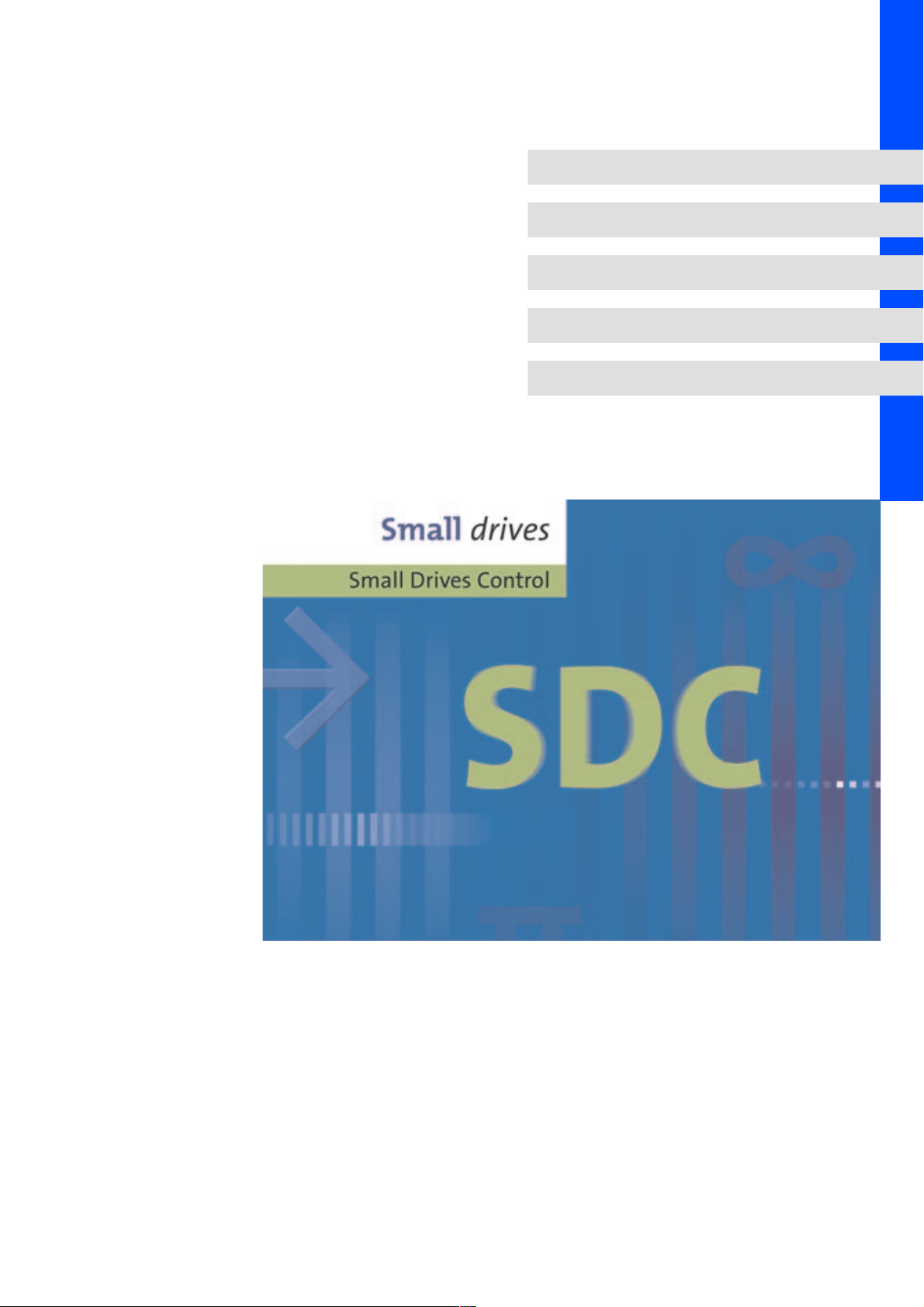
Fig. 1 Basic wiring of CANopen with Sub-D connector to the master
Node 1 - master (e.g. PLC)
A
1
A
Node 2 - slave (e.g. drive controller 931E)
2
A
Node n - slave, n = max. 128
n
Specification of the transmission cable
Please observe our recommendations for signal cables.
Bus cable specification
Cable resistance 135 - 165 Ω/km,(f=3-20MHz)
Capacitance per unit length ≤ 30 nF/km
Loop resistance < 110 Ω/km
Wire diameter >0.64mm
Wire cross-section >0.34mm
Wires double twisted, insulated and shielded
2
PES
A
n
W
120
931e_420
KHB 13.0002-EN 2.0
ƒ Connection of the bus terminating resistors:
– One resistor of 120 Ω each at the first and last bus node
ƒ Communication protocol
– CANopen (CAL-based communication profile DS 301/DSP 402)
ƒ Bus extension:
– 25 m for max. data transfer rate of 1 Mbps
– Up to 1 km for reduced data transfer speed
ƒ Signal level according to ISO 11898
ƒ Up to 128 bus nodes possible
ƒ Access to all Lenze parameters
15
4
efesotomasyon.com - Lenze
Electrical installation
Connection of CAN bus slave
4.3 Connection of CAN bus slave
Features
ƒ Parameter selection
ƒ Data exchange between drive controllers
ƒ Connection of operator and input devices
ƒ Connection of higher-level controls
ƒ Baud rates of 125, 250, 500 kBaud
Stop!
An external 120 Ω terminating resistor is required to terminate the bus system.
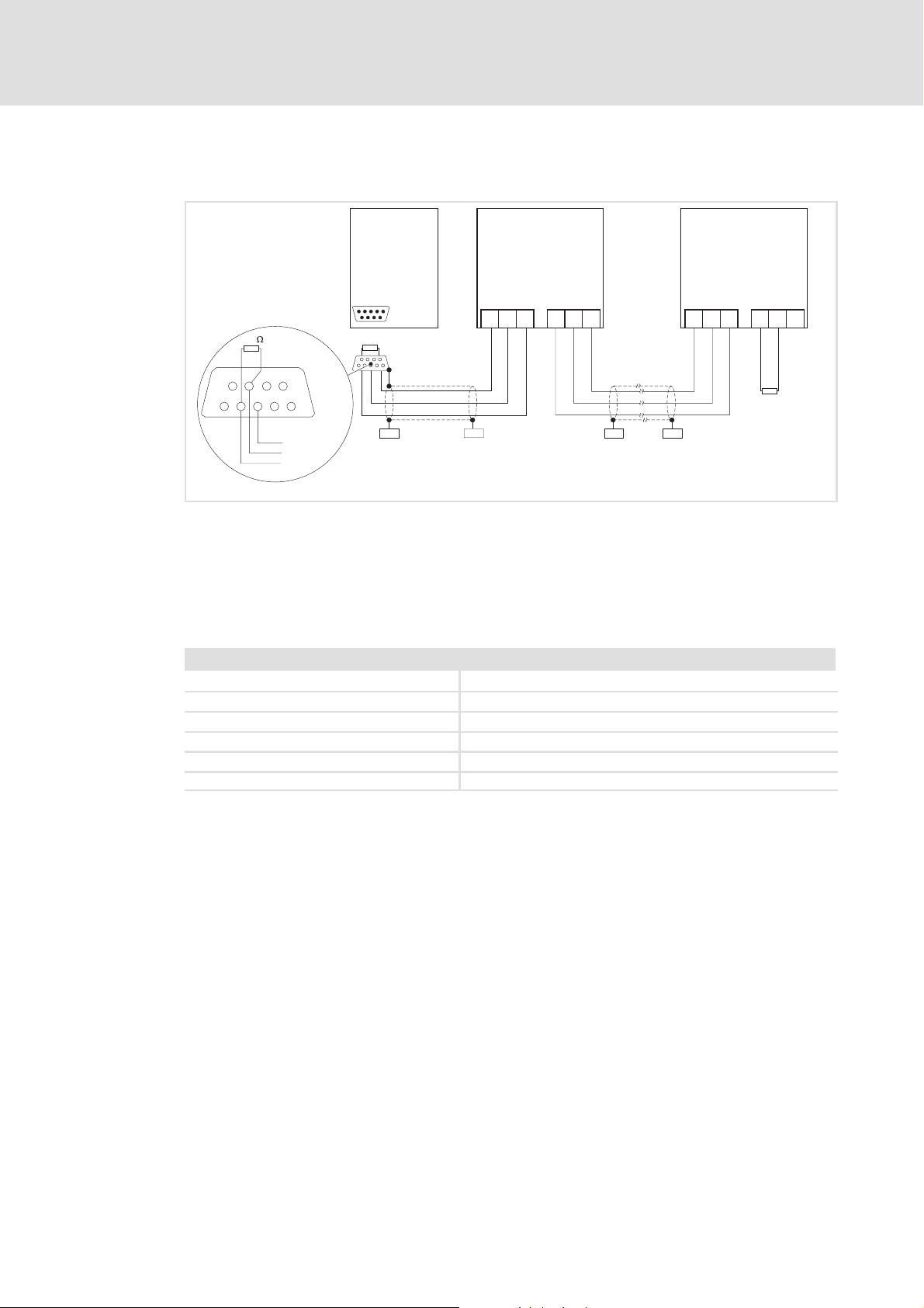
Connection plan for RJ45 socket
X4.1 / X4.2
Fig. 2 Connection of CAN bus (X4.1, X4.2)
Pin no. Meaning Comment
1CAN-HIGH CAN-HIGH (high is dominant)
2 CAN-LOW CAN-LOW (low is dominant)
3 CAN-GND CAN ground
4 — Reserved
5 — Reserved
6 CAN-SHLD CAN shield (hardware version 1.1 and higher)
7 CAN-GND CAN ground
8 — Reserved
Tip!
An RJ45 bus terminating connector is available for the 931E drive controllers.
Please contact Lenze.
931E-001.iso
16
KHB 13.0002-EN 2.0

4.4 Connection of CAN bus master
efesotomasyon.com - Lenze
The below table shows the assignment of a 9-pin Sub-D socket such as provided by most
CAN masters for the connection of field devices.
Connection of the CAN bus to a 9-pin Sub-D socket
View Pin Signal Explanation
1
2
3
4
5
Tab. 1 CAN Sub-D socket
1 — Reserved
6
2 CAN-LOW CAN-LOW (low is dominant)
7
3 CAN-GND CAN ground
8
4 — Reserved
9
5 (CAN-SHLD) Optional CAN shield
6 (GND) Optional ground
7 CAN-HIGH CAN-HIGH (high is dominant)
8 — Reserved
9 (CAN-V+) Optional external CAN voltage supply
Electrical installation
Connection of CAN bus master
4
KHB 13.0002-EN 2.0
17
5
efesotomasyon.com - Lenze
CANopen communication
About CANopen
Structure of the CAN data telegram
5 CANopen communication
5.1 About CANopen
The CANopen protocol isa standardisedlayer 7protocol forthe CAN bus. This layeris based
on the CAN application layer (CAL), which has been developed as a universal protocol.
In practice, however, it became clear that applications with CAL were too complex for the
user. CANopen is a uniform, easy-to-use structure which has been developed to provide a
connection for CAN devices from different manufacturers.
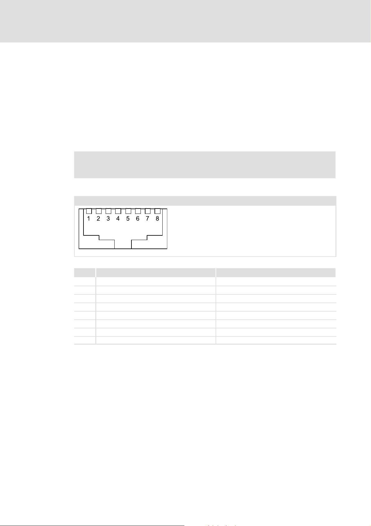
5.1.1 Structure of the CAN data telegram
Control field CRC delimit. ACK delimit.
Start RTR bit
CRC sequence ACK slot End
Identifier Data
length
1bit 11 bits 1bit 2bits 4bits 15bits 1bit 1bit 1bit 7bits
Fig. 3 Basic structure of the CAN telegram
User data (0 ... 8 bytes)
z Network management
z Process data
z Parameter data
Note!
To the user, only the identifier, the data length and the user data are relevant.
All other data of the CAN telegram is automatically processed by the system.
18
KHB 13.0002-EN 2.0

5.1.2 Identifier
efesotomasyon.com - Lenze
The principle of the CAN communication is based on a message-oriented data exchange
between one sender and many receivers. All nodes can send and receive
quasi-simultaneously.
The identifier in the CAN telegram - also called COB ID (communication object identifier)is used to control which node is to receive a sent message. In addition to the addressing,
the identifier contains information on the priority of the message and on the type of the
user data.
With the exception of the network management and the sync telegram, the identifier
contains the node address of the drive:
Identifier (COB ID) = basic identifier + adjustable node address (node ID)
The identifier assignment is specified in the CANopen protocol.
The ex works default setting of the basic identifier is:
CANopen communication
About CANopen
Identifier
5
Object
NMT 0
Sync 80
Emergency X 80
PDO1
(process data channel 1)
PDO2
(process data channel 2)
SDO1
(parameter data channel 1)
Heartbeat/boot-up X 700
5.1.3 Node address ( node ID)
Each node of the CAN network must be assigned with a node address (also called node ID)
within the valid address range for unambiguous identification.
ƒ A node address may not be assigned more than once within a network.
TPDO1
RPDO1
TPDO2
RPDO2
Direction Basic identifier
From the drive To the drive Hex
X 180
X 200
X 280
X 300
X 580
X 600
KHB 13.0002-EN 2.0
19

5
efesotomasyon.com - Lenze
5.1.4 User data
CANopen communication
About CANopen
User data
The master and the drive controller communicate with each other by exchanging data
telegrams via the CAN bus.
The user data range of the C AN telegram contains network management data, parameter
data or process data:
ƒ Network management data (NMT data)
Network service: E.g. all CAN nodes can be addressed at the same time.
ƒ Process data (PDO, process data objects)
– Process data is transferred via the process data channel.
– Process data can be used to control the drive controller.
– The master can directly access the process data. The data is, for instance, directly
assigned to the I/O area of the master. It is necessary that the control and the drive
controller can exchange data within a very short time interval. For this purpose,
small amounts of data can be transferred cyclically.
– Process data is not stored in the drive controller.
– Process data is transferred between the master and the drive controllers to ensure
a continuous exchange of current input and output data.
– Examples for process data are, for instance, setpoints and actual values.
ƒ Parameter data (SDO, service data objects)
– Parameters are set, for instance, for the initial system set-up during
commissioning or when the material is changed on a production machine.
– Parameter data is transferred by means of so-called SDOs via the parameter data
channel. The transfer is acknowledged by the receiver, i.e. the sender gets a
feedback about the transfer being successful or not.
– The parameter data channel enables the access to all CANopen indexes.
– Parameter changes are automatically stored in the drive controller.
– In general, the transfer of parameters is not time-critical.
– Examples for parameter data are, for instance, operating parameters, diagnostic
information and motor data.
20
KHB 13.0002-EN 2.0

Parameter data transfer (SDO transfer)
efesotomasyon.com - Lenze
5.2 Parameter data transfer (SDO transfer)
5.2.1 Telegram structure
The telegram for parameter data has the following structure:
11 bits 4bits User data (up to 8 bytes)
1st byte 2nd byte 3rd byte 4th byte 5th byte 6th byte 7th byte 8th byte
Identifier
ƒ The following subchapters explain in detail the different parts of the telegram.
Data
length
Command
code
Index
low byte
high byte
Identifier
11 bits 4bits User data (up to 8 bytes)
Identifier
Data
length
Command
code
Index
low byte
high byte
With the exception of the network management and the sync telegram, the identifier
contains the node address of the drive:
CANopen communication
Telegram structure
Index
Index
Subindex
Subindex
Data 1 Data 2 Data 3 Data 4
Data 1 Data 2 Data 3 Data 4
5
Error code
Identifier (COB ID) = basic identifier + adjustable node address (node ID)
The identifier assignment is specified in the CANopen protocol.
The ex works default setting of the basic identifier is:
Object
SDO (parameter data channel)
From the drive To the drive Hex
Direction Basic identifier
X 580
X 600
KHB 13.0002-EN 2.0
21

5
efesotomasyon.com - Lenze
CANopen communication
Parameter data transfer (SDO transfer)
Telegram structure
Command code
11 bits 4bits User data (up to 8 bytes)
1st byte 2nd byte 3rd byte 4th byte 5th byte 6th byte 7th byte 8th byte
Identifier
Data
length
Command
code
Index
low byte
Index
high byte
Subindex
Data 1 Data 2 Data 3 Data 4
Error code
The command code contains the services for writing and reading parameters and the
information on the length of the user data.
Structure of the command code:
Bit 7
Bit 6 Bit 5 Bit 4 Bit 3 Bit 2 Bit 1 Bit 0
MSB
Write command code
Write command / write request 0 0 1 0 x x 1 1
Response to write command / write
response
Read command code CS 0 Length e s
Read command / read request 0 1 0 0 x x 0 0
Response to read command / read
response
Error command code CS 0 Length e s
Error response 1 0 0 0 0 0 0 0
CS 0 Length e s
0 1 1 0 x x 0 0
0 1 0 0 x x 1 1
LSB
Comment
CS: command
specifier
User data length
is coded in bits 2
and 3:
z 00=4bytes
z 01=3bytes
z 10=2bytes
z 11=1byte
The command code specifies whether a value is to be read or written. The command code
also determines the data length (1 byte, 2 bytes, 4 bytes).
Write command code
Write command / write request
(Send parameters to t he drive)
Response to write command / write response
(Response of the drive controller to the write request
(acknowledgement))
Read command code
Read command / read request
(Request to read a parameter from the drive controller)
Response to read command / read response
(Response to the read request with the actual value)
Error command code
Error response
(The drive controller signals a communication error)
4-byte data
(5th ... 8th byte)
hex hex hex
23 2B 2F
60 60 60
40 40 40
43 4B 4F
80 80 80
2-byte data
(5th and 6th byte)
1-byte data
(5th byte)
22
KHB 13.0002-EN 2.0

CANopen communication
efesotomasyon.com - Lenze
Parameter data transfer (SDO transfer)
Telegram structure
Index low byte / index high byte
11 bits 4bits User data (up to 8 bytes)
1st byte 2nd byte 3rd byte 4th byte 5th byte 6th byte 7th byte 8th byte
Identifier
Data
length
The object to be addressed is contained in bytes 2 and 3 of the telegram.
ƒ The value for the index is split up into low byte and high byte and entered in the
left-justified Intel format.
Subindex
11 bits 4bits User data (up to 8 bytes)
Identifier
ƒ If an object (e.g. controller parameter) consists of several sub-objects, the
Data
length
sub-objects are addressed via subindexes. The number of the corresponding
subindex is entered in byte 4 of the telegram. (See following tables for sub-objects).
Command
code
1st byte 2nd byte 3rd byte 4th byte 5th byte 6th byte 7th byte 8th byte
Command
code
Index
low byte
Index
low byte
Index
high byte
Index
high byte
Subindex
Subindex
Data 1 Data 2 Data 3 Data 4
Data 1 Data 2 Data 3 Data 4
5
ƒ If an object has no sub-objects, the value ”0” is entered in byte 4 of the telegram.
(See following sub-object tables).
Data (data 1 ... data 4)
11 bits 4bits User data (up to 8 bytes)
1st byte 2nd byte 3rd byte 4th byte 5th byte 6th byte 7th byte 8th byte
Identifier
Data
length
Command
code
Index
low byte
Index
high byte
Subindex
Data 1 Data 2 Data 3 Data 4
For the data of the parameter up to 4 bytes (data 1 ... data 4) are available.
The data is represented in the left-justified Intel format with data 1 as the LSB and data 4
as the MSB.
KHB 13.0002-EN 2.0
23

5
efesotomasyon.com - Lenze
CANopen communication
Parameter data transfer (SDO transfer)
Telegram structure
Error code (F0 ... F3)
11 bits 4bits User data (up to 8 bytes)
1st byte 2nd byte 3rd byte 4th byte 5th byte 6th byte 7th byte 8th byte
Identifier
ƒ Byte 1:
Code 80
ƒ Bytes 2, 3 and 4:
Data
length
in the command code byte indicates that an error has occurred.
h
Command
code
Index
low byte
Index
high byte
Subindex
F0 F1 F2 F3
Error code
These bytes contain the index (bytes 2 and 3) and the subindex (byte 4) at which an
error occurred.
ƒ Bytes 5 to 8:
The data bytes 5 to 8 contain the error code. The error code is represented opposite
to the direction of reading.
Example:
The representation of the error code 06 04 00 41
in bytes 5 to 8
h
Reading direction of the error code
41 00 04 06
5th byte 6th byte 7th byte 8th byte
Low word High word
Low byte High byte Low byte High byte
The below table lists the meanings of the error codes:
Error code Explanation
F3 F2 F1 F0
06 01 00 00 Access to object is not supported
06 01 00 01 Attempt to read a write-only object
06 01 00 02 Attempt to write to a read-only object
06 02 00 00 Object does not exist in the object directory
06 04 00 41 Object cannot be mapped to the PDO
06 04 00 42 The number and length of objects to be mapped would exceed PDO length.
06 07 00 10 Data type does not match, length of service parameter does not match
06 07 00 12 Data type does not match, length of service parameter is too large
06 07 00 13 Data type does not match, length of service parameter is too small
06 09 00 11 Subindex does not exist
06 09 00 30 Value range of parameter exceeded
06 09 00 31 Parameter values too large
06 09 00 32 Parameter values too small
08 00 00 20 Data cannot be transferred/saved to the application.
08 00 00 21 Data cannot be transferred/saved to the application due to local control.
08 00 00 22 Data cannot be transferred/saved to the application due to current device state.
24
KHB 13.0002-EN 2.0

5.2.2 Reading parameters (example)
efesotomasyon.com - Lenze
Problem
The numerator setting (object 6093_01) of the drive controller with node address 1 is to
be read via the parameter channel.
Telegram to the drive controller
Value Info
Identifier = Basic identifier + node address
=600+1=601
Data length = 08
Command code = 40
Index = 6093
h
h
Subindex = 1 z Subindex = 1 (numerator)
Data 1
Data 2
Data 3
Data 4
Data 1 ... 4
=00
h
=00
h
=00
h
=00
h
= 00 00 00 00
h
h
CANopen communication
Parameter data transfer (SDO transfer)
Reading parameters (example)
z Basic identifier for parameter channel = 600
z Node address = 1
z “Read request” command (request to read a
parameter)
z Index of the position_factor
z Read request only
5
h
11 bits 4bits User data
Identifier
601
h
Data
length
08
h
Command
code
40
h
Index
low byte
93
h
Index
high byte
60
h
Subindex
01
h
Data 1 Data 2 Data 3 Data 4
00
h
Telegram from the drive controller
Value Info
Identifier = Basic identifier + node address
=580+1=581
h
Data length = 08
Command code = 43
Index = 6093
h
h
Subindex = 1 z Subindex = 1 (numerator)
Data 1
Data 2
Data 3
Data 4
Data 1 ... 4
=C0
h
=4B
h
=03
h
=00
h
= C0 4B 03 00
h
11 bits 4bits User data
Identifier
581
h
Data
length
08
h
Command
code
43
h
Index
low byte
93
h
z Basic identifier for parameter channel = 580
z Node address = 1
z “Read response” command (response to the read
request with the actual value)
z Index of the position_factor
z Assumption: The set numerator value is 00 03 4B C0
(216000d).
Index
high byte
60
h
Subindex
01
Data 1 Data 2 Data 3 Data 4
h
C0
h
00
4B
h
h
00
03
h
h
00
h
h
h
00
h
KHB 13.0002-EN 2.0
25

5
efesotomasyon.com - Lenze
CANopen communication
Parameter data transfer (SDO transfer)
Writing parameters (example)
5.2.3 Writing parameters (example)
Problem
The numerator (object 6093_01) of the drive controller with node address 1 is to be set to
216000 via the SDO (parameter data channel).
Telegram to the drive controller
Value Info
Identifier = Basic identifier + node address
=600+1=601
Data length = 08
Command code = 23
Index = 6093
h
h
Subindex = 1 z Subindex = 1 (numerator)
Data 1
Data 2
Data 3
Data 4
Data 1 ... 4
=C0
h
=4B
h
=03
h
=00
h
= C0 4B 03 00
h
h
z Basic identifier for parameter channel = 600
z Node address = 1
z “Write request” command (send parameter to the
h
drive)
z Index of the position_factor
z Assumption: The numerator value to be set is to be
00 03 4B C0
(216000d).
h
11 bits 4bits User data
Identifier
601
h
Data
length
08
h
Command
code
23
h
Index
low byte
93
h
Index
high byte
60
h
Subindex
01
h
Data 1 Data 2 Data 3 Data 4
C0
h
4B
h
03
h
Telegram from the drive controller (acknowledgement for faultless execution)
Value Info
Identifier = Basic identifier + node address
=580+1=581
h
Data length = 08
Command code = 60
Index = 6093
h
h
Subindex = 1 z Subindex = 1 (numerator)
Data 1 ... 4 = 00 00 00 00
h
11 bits 4bits User data
Identifier
581
h
Data
length
08
h
Command
code
60
h
Index
low byte
93
h
z Basic identifier for parameter channel = 580
z Node address = 1
z “Write response” command (acknowledgement from
the drive controller)
z Index of the position_factor
z Acknowledgement only
Index
high byte
60
h
Subindex
01
Data 1 Data 2 Data 3 Data 4
h
00
h
00
h
00
h
00
h
h
00
h
26
KHB 13.0002-EN 2.0

5.3 Process data transfer (PDO transfer)
efesotomasyon.com - Lenze
Process data objects (PDOs)can beused, forinstance, forthe fastevent-controlled transfer
of data. The PDO transfers one or several parameters specified in advance. Unlike with an
SDO, the transfer of a PDO is not acknowledged. After the PDO activation, all receivers
must therefore always be able to process any arriving PDOs. This usually means a
considerable software load on the master. However, this disadvantage is compensated by
the advantage that the master does not need to cyclically poll the parameters transferred
by a PDO, which results in a significant reduction of the CAN bus load.
Example:
The master wants to know when the drive controller has completed the positioning from
AtoB.
When SDOs areused for this purpose, the master continuously (e.g. every millisecond) has
to poll the status word object, i.e. the load on the bus is high.
When a PDO is used, right from the start of the application the drive controller is
parameterised in such a way that it transmits a PDO containing the status word object as
soon as the status word object changes.
CANopen communication
Process data transfer (PDO transfer)
Telegram structure
5
Instead of polling continuously, the master automatically receives a corresponding
message as soon as the event has occurred.
The following types of process data telegram are distinguished
ƒ Process data telegrams to the drive controller: Receive PDO (RPDOx)
ƒ Process data telegrams from the drive controller: Transmit PDO (TPDOx)
5.3.1 Telegram structure
The telegram for process data has the following structure:
11 bits 4bits User data (up to 8 bytes)
1st byte 2nd byte 3rd byte 4th byte 5th byte 6th byte 7th byte 8th byte
Identifier
Data
length
Data 0 Data 1 Data 2 Data 3 Data 4 Data 5 Data 6 Data 7
5.3.2 Available process data objects
The drive controller is provided with two transmit and two receive PDOs.
Almost all objects of the object directory can be entered in (mapped to) the PDOs, i.e. the
PDO containsfor instance theactual speed value or actual positionvalue as data.The drive
controller must know in advance which data is to be transferred because the PDO only
contains user data and no information about the type of the parameter.
In this way almost all kinds of data telegrams can be defined. The settings required are
described in the following chapters.
KHB 13.0002-EN 2.0
27

5
efesotomasyon.com - Lenze
CANopen communication
Process data transfer (PDO transfer)
Objects for PDO parameterisation
5.3.3 Objects for PDO parameterisation
Two transmit PDOs (TPDO) and two receive PDOs (RPDO) are available in the drive
controller. The different objects of the PDOs are identical.
1. Transmit PDO
Index Name Possible settings
Lenze Selection Description
1800
Transmit PDO1
h
Communication
Parameter
0 number_of_entries
1 COB-ID_used_by_
PDO
2 transmission_type 255
3 inhibit_time 0
00000181
h
Characteristics
00
h
03
h
00000181
Bit no. Value
0-10 x 11-bit identifier
11 - 28 0
29 0
30
31
0 {1} 240, 254, 255 —
0 Function is switched off
n = 1 ... 240 By entering a value n, this
n = 254, 255 Event-controlled
0 {0.1 ms} 65535 —
h
0 RTR of this PDO is permitted
1 RTR of this PDO is not
0 PDO is active
1 PDO is inactive
{1h} 04
{1h} 000001FF
REC UINT8 RO —
h
Maximum number of
supported subindexes.
3 subindexes are supported.
— UINT32 RW —
h
Identifier of transmit PDO1,
+ node address).
(180
h
For processing, bits 30 and
31 must be set
(parameterisation of
mapping).
The extended identifier
(bit 29) is not supported.
Each bit of this range must
be ”0”.
(Lenze).
permitted (unadjustable).
UINT8 RW —
Setting of the transmission
mode
PDO is accepted with every
n-th sync.
transmission mode
UINT16 RW —
Setting of the minimum
delay time between two
PDOs. The time can only be
changed if the PDO is not
active (subindex 1, bit 31 = 1)
28
KHB 13.0002-EN 2.0

CANopen communication
efesotomasyon.com - Lenze
Process data transfer (PDO transfer)
Objects for PDO parameterisation
5
Index Name Possible settings
Lenze Selection Description
1A00
Transmit PDO1
h
Mapping Parameter
0 number_of_
mapped_objects
1 first_mapped_
object
2 second_mapped_
object
...
4 fourth_mapped_
object
60410010
h
00
01
Characteristics
h
h
{1h} 04
{1h}
REC UINT32 RW —
h
Maximum number of
supported subindexes.
1 subindex is supported.
— UINT32 RW —
EntryoftheCOBIDofthe
first mapped object.
— UINT32 RW —
Not supported.
— UINT32 RW —
Not supported.
KHB 13.0002-EN 2.0
29

5
efesotomasyon.com - Lenze
CANopen communication
Process data transfer (PDO transfer)
Objects for PDO parameterisation
2. Transmit PDO
Index Name Possible settings
Lenze Selection Description
1801
Transmit PDO2
h
Communication
Parameter
0 number_of_entries
1 COB-ID_used_by_
PDO
2 transmission_type 255
3 inhibit_time 0
00000281
h
Characteristics
00
h
03
h
00000281
Bit no. Value
0-10 x 11-bit identifier
11 - 28 0
29 0
30
31
0 {1} 240, 254, 255 —
0 Function is switched off
n = 1 ... 240 By entering a value n, this
n = 254, 255 Event-controlled
0 {0.1 ms} 65535 —
h
0 RTR of this PDO is permitted
1 RTR of this PDO is not
0 PDO is active
1 PDO is inactive
{1h} 04
{1h} 000002FF
REC UINT8 RO —
h
Maximum number of
supported subindexes
3 subindexes are supported.
— UINT32 RW —
h
Identifier of transmit PDO2,
+ node address).
(280
h
For processing, bits 30 and
31 must be set
(parameterisation of
mapping).
The extended identifier
(bit 29) is not supported.
Each bit of this range must
be ”0”.
(Lenze)
permitted (unadjustable)
UINT8 RW —
Setting of the transmission
mode
PDO is accepted with every
n-th sync.
transmission mode
UINT16 RW —
Setting of the minimum
delay time between two
PDOs. The time can only be
changed if the PDO is not
active (subindex 1, bit 31 = 1)
30
KHB 13.0002-EN 2.0

CANopen communication
efesotomasyon.com - Lenze
Process data transfer (PDO transfer)
Objects for PDO parameterisation
5
Index Name Possible settings
Lenze Selection Description
1A01
Transmit PDO2
h
Mapping Parameter
0 number_of_
mapped_objects
1 first_mapped_
object
2 second_mapped_
object
3 third_mapped_
object
4 fourth_mapped_
object
60410010
60610008
h
h
00
02
Characteristics
h
h
{1h} 04
{1h}
{1h}
REC UINT32 RW —
h
Maximum number of
supported subindexes.
2 subindexes are supported.
— UINT32 RW —
EntryoftheCOBIDofthe
first mapped object.
— UINT32 RW —
EntryoftheCOBIDofthe
second mapped object.
— UINT32 RW —
Not supported.
— UINT32 RW —
Not supported.
KHB 13.0002-EN 2.0
31

5
efesotomasyon.com - Lenze
CANopen communication
Process data transfer (PDO transfer)
Objects for PDO parameterisation
1. Receive PDO
Index Name Possible settings
Lenze Selection Description
1400
Receive PDO1
h
Communication
Parameter
0 number_of_entries
1 COB-ID_used_by_
PDO
2 transmission_type 255
00000201
h
Characteristics
00
h
02
h
00000201
Bit no. Value
0-10 x 11-bit identifier
11 - 28 0
29 0
30
31
0 {1} 240, 254, 255 —
0 Function is switched off
n = 1 ... 240 By entering a value n, this
n = 254, 255 Event-controlled
h
0 RTR of this PDO is permitted
1 RTR of this PDO is not
0 PDO is active
1 PDO is inactive
{1h} 04
{1h} 000002FF
REC UINT8 RO —
h
Maximum number of
supported subindexes
2 subindexes are supported.
— UINT32 RW —
h
Identifier of receive PDO1
+ node address)
(200
h
For processing, bits 30 and
31 must be set
(parameterisation of
mapping).
The extended identifier
(bit 29) is not supported.
Each bit of this range must
be ”0”.
(Lenze)
RTR = remote transmission
request
permitted (unadjustable)
UINT8 RW —
Setting of the transmission
mode
PDO is accepted with every
n-th sync.
transmission mode, PDO is
accepted immediately
32
KHB 13.0002-EN 2.0

CANopen communication
efesotomasyon.com - Lenze
Process data transfer (PDO transfer)
Objects for PDO parameterisation
5
Index Name Possible settings
Lenze Selection Description
1600
Receive PDO1
h
Mapping Parameter
0 number_of_
mapped_objects
1 first_mapped_
object
2 second_mapped_
object
...
4 fourth_mapped_
object
60400010
h
00
01
Characteristics
h
h
{1h} 04
{1h}
REC UINT32 RW —
h
Maximum number of
supported subindexes.
1 subindex is supported.
— UINT32 RW —
EntryoftheCOBIDofthe
first mapped object.
— UINT32 RW —
Not supported.
— UINT32 RW —
Not supported.
KHB 13.0002-EN 2.0
33

5
efesotomasyon.com - Lenze
CANopen communication
Process data transfer (PDO transfer)
Objects for PDO parameterisation
2. Receive PDO
Index Name Possible settings
Lenze Selection Description
1401
Receive PDO2
h
Communication
Parameter
0 number_of_entries
1 COB-ID_used_by_
PDO
2 transmission_type 255
00000301
h
Characteristics
00
h
02
h
00000301
Bit no. Value
0-10 x 11-bit identifier
11 - 28 0
29 0
30
31
0 {1} 240, 254, 255 —
0 Function is switched off
n = 1 ... 240 By entering a value n, this
n = 254, 255 Event-controlled
h
0 RTR of this PDO is permitted
1 RTR of this PDO is not
0 PDO is active
1 PDO is inactive
{1h} 04
{1h} 000003FF
REC UINT8 RO —
h
Maximum number of
supported subindexes
2 subindexes are supported.
— UINT32 RW —
h
Identifier of receive PDO2
+ node address)
(300
h
For processing, bits 30 and
31 must be set
(parameterisation of
mapping).
The extended identifier
(bit 29) is not supported.
Each bit of this range must
be ”0”.
(Lenze)
RTR = remote transmission
request
permitted (unadjustable)
UINT8 RW —
Setting of the transmission
mode
PDO is accepted with every
n-th sync.
transmission mode, PDO is
accepted immediately
34
KHB 13.0002-EN 2.0

CANopen communication
efesotomasyon.com - Lenze
Process data transfer (PDO transfer)
Objects for PDO parameterisation
5
Index Name Possible settings
Lenze Selection Description
1601
Receive PDO2
h
Mapping Parameter
0 number_of_
mapped_objects
1 first_mapped_
object
2 second_mapped_
object
3 third_mapped_
object
4 fourth_mapped_
object
60400010
60600008
h
h
00
02
Characteristics
h
h
{1h} 04
{1h}
{1h}
REC UINT32 RW —
h
Maximum number of
supported subindexes.
2 subindexes are supported.
— UINT32 RW —
EntryoftheCOBIDofthe
first mapped object.
— UINT32 RW —
EntryoftheCOBIDofthe
second mapped object.
— UINT32 RW —
Not supported.
— UINT32 RW —
Not supported.
KHB 13.0002-EN 2.0
35

5
efesotomasyon.com - Lenze
CANopen communication
Process data transfer (PDO transfer)
Objects for PDO parameterisation
1. Transmit masking
Index Name Possible settings
Lenze Selection Description
2014
h
Transmit PDO1
Mask
0 number_of_entries
1 tpdo1_transmit_
mask_low
2 tpdo1_transmit_
mask_high
FFFFFFFF
FFFFFFFF
h
h
2. Transmit masking
Index Name Possible settings
Lenze Selection Description
2015
Transmit PDO2
h
Mask
0 number_of_entries
1 tpdo2_transmit_
mask_low
2 tpdo2_transmit_
mask_high
FFFFFFFF
FFFFFFFF
h
h
00000000
00000000
00000000
00000000
Characteristics
ARR UINT8 RO —
Maximum number of
supported subindexes
h
{1h} FFFFFFFF
— UINT32 RW —
h
Mask for masking out
individual bits of the PDOs.
h
{1h} FFFFFFFF
— UINT32 RW —
h
Mask for masking out
individual bits of the PDOs.
Characteristics
ARR UINT8 RO —
Maximum number of
supported subindexes
h
{1h} FFFFFFFF
— UINT32 RW —
h
Mask for masking out
individual bits of the PDOs.
h
{1h} FFFFFFFF
— UINT32 RW —
h
Mask for masking out
individual bits of the PDOs.
36
KHB 13.0002-EN 2.0

5.3.4 Description of the objects
efesotomasyon.com - Lenze
Identifier of the PDO (COB_ID_used_by_PDO)
The identifier on which the respective PDO is to be sent or received must be entered in the
COB_ID-used_by_PDO object. If bit 31 is set, the respective PDO is deactivated. This is the
defaultsetting forall PDOs.In addition, bit30 (noRTR allowed)must be set for everyaccess.
The COB ID can only be changed if the PDO is deactivated, i.e. if bit 31 is set. For changing
the COB ID, you therefore have to keep to the following sequence:
ƒ Read out the COB ID
CANopen communication
Process data transfer (PDO transfer)
Description of the objects
5
ƒ Write the read-out COB ID + C0000000
ƒ Write the new COB ID + C0000000
ƒ Write the new COB ID, the PDO is active again.
h
h
Transmission mode (transmission_type and inhibit_time)
For each PDO, the event leading to a message being sent (transmit PDO) or evaluated
(receive PDO) can be defined:
Value Meaning Permitted for
00h-F0
FE
h
FF
h
Sync telegram
h
The numerical value specifies how many sync telegrams are ignored between two
transmissions before the PDO is
- sent (TPDO) or
-evaluated(RPDO).
Cyclic
The TPDO is cyclically updated and sent by the drive controller. The time interval is
specified with the inhibit_time object.
RPDOs, however, are evaluated immediately after the receipt.
Change
TheTPDOissentifatleastonebitofthePDOdatahaschanged.
The inhibit_time can be used to additionally specify the minimum time interval (in
100 μs steps) between the transmission of two PDOs.
TPDO
RPDO
TPDO
(RPDO)
TPDO
KHB 13.0002-EN 2.0
The use of all other values is not permitted.
Number of objects to be transferred (number_of_mapped_objects)
This object specifies how many objects are to be mapped into the corresponding PDO. The
following restrictions have to be taken into account:
ƒ It is not possible to map more than 4 objects per PDO
ƒ A PDO can have a maximum of 64 bits (8 bytes).
37

5
efesotomasyon.com - Lenze
CANopen communication
Process data transfer (PDO transfer)
Description of the objects
Objects to be transferred (first_mapped_object ... fourth_mapped_object)
For every object to be contained in the PDO, the drive controller must know the
corresponding i ndex, subindex and length. The specified length must be identical to the
length specified in the object dictionary. It is not possible to map parts of an object.
The mapping information has the following format:
Index Subindex Length
16 bits 8bits 8bits
ƒ Index: Main index of the object to be mapped (hex)
ƒ Subindex: Subindex of the object to be mapped (hex)
ƒ Length: Length of the object (hex)
The following mandatory procedure serves to simplify the mapping:
1. The number of the mapped objects is set to 0.
2. The first_mapped_object ... fourth_mapped_object parameters can be written (the
total length of all objects is not relevant at this time).
3. The number of the mapped objects is set to a value between 1 ... 4. The total length
of these objects must not exceed 64 bits.
Masking (transmit_mask_high
If ”change” is selected for the transmission_type, the TPDO is always sent if at least 1 bit
of the TPDO has changed.
However, very often it is necessary to send the TPDO only if a certain bit has changed. For
this purpose, the TPDO can be provided with a mask. Only those bits of the TPDO are
evaluated which are set to ”1” in the mask.
In the default setting all bits of the masks are set.
and transmit_mask_low)
38
KHB 13.0002-EN 2.0

5.3.5 Example of a process data telegram
efesotomasyon.com - Lenze
The following objects are to be transferred together in a PDO:
CANopen communication
Process data transfer (PDO transfer)
Example of a process data telegram
5
ƒ Status word, index 6041_00
ƒ Modes_of_operation_display, index 6061_00
ƒ Digital_inputs, index 60FD_00
(controller control),
h
(digital inputs)
h
(operating mode)
h
The first transmitPDO (TPDO 1) is to be used, and it is alwaysto be sent if one of the digital
inputs changes, but not more often than every 10 ms. The identifier used for this PDO is to
be 187
.
h
1. Delete the number of objects.
Description Name Value
To enable the change of the object mapping, the number of
objects has to be set to zero.
number_of_mapped_objects 0
2. Parameterise the objects which are to be mapped.
Description Name Value
The objects listed above have to be composed to form a 32-bit
value:
Index = 6041h, subindex = 00h,length=10h(UINT16) first_mapped_object 60410010
Index = 6061h, subindex = 00h,length=08h(INT8) second_mapped_object 60610008
Index = 60FDh, subindex = 00h,length=20h(UINT32) third_mapped_object 60FD0020
h
h
h
3. Parameterise the number of objects.
Description Name Value
The PDO has to contain 3 objects number_of_mapped_objects 3
h
4. Parameterise the transmission mode.
Description Name Value
The PDO has to be sent if one or several of the above digital
inputs change.
In order to ensure that only changes of the digital inputs cause
the transmission of the PDO, it is masked in such a way that
only the above 16 bits of the object 60FD
The PDO is to be sent not more often than every 10 ms
(100 × 100 μs).
”come through”.
h
transmission_type FF
transmit_mask_high 00FFFF00
transmit_mask_low 00000000
inhibit_time 64
h
h
5. Parameterise the identifier.
Description Name Value
The PDO is to be sent with the identifier 187h.IfthePDOis
active, it first has to be deactivated.
Read out the identifier: cob_id_used_by_pdo 00000181
Set bit 31 (deactivate PDO): cob_id_used_by_pdo C0000181
Write new identifier: cob_id_used_by_pdo C0000187
Activate PDO by deleting bit 31: cob_id_used_by_pdo 40000187
Note!
The parameterisation of the PDO can only be changed if the network state
(NMT) is not operational.
h
h
h
h
h
h
KHB 13.0002-EN 2.0
39

5
efesotomasyon.com - Lenze
5.3.6 Activation of the PDOs
CANopen communication
Process data transfer (PDO transfer)
Activation of the PDOs
The following criteria must be met to enable the drive controller to send or receive PDOs:
ƒ The number_of_mapped_objects object must be non-zero.
ƒ Bit 31 of the cob_id_used_for_pdos object must be deleted.
ƒ The communication state of the controller must be operational (see chapter 5.5,
network management).
The following criterion must be met to enable the parameterisation of PDOs:
ƒ Thecommunicationstateofthedrivecontrollermustnotbeoperational.
40
KHB 13.0002-EN 2.0

5.4 Sync telegram
efesotomasyon.com - Lenze
The sync telegram is an additional and special telegram which enables the drive controller
to cyclically read / accept process data.
5.4.1 Telegram structure
11 bits 4bits
Identifier
Data
length
The identifier on which the drive controller receives the sync telegram is permanently set
to 080
. The data length is 0.
h
5.4.2 Synchronisation of the process data
The sync telegram is the trigger point for data acceptance in the drive controller and it
starts the sending process of the drive controller. Cyclic process data processing requires
an appropriate generation of the sync telegram.
CANopen communication
Sync telegram
Telegram structure
5
PDO1-TX PDO1-RX
1.
Fig. 4 Synchronisation of cyclic process data by means of a sync telegram (without consideration of
asynchronous data)
c
Sync telegram
2. 3. 4.
epm-t111
Transmission sequence
1. After the sync telegram has been received, the cyclic process data are send from the
drive controllers to the master. The data is read by the master as process input data.
2. When the sending process is completed, the process output data (of the master) is
received by the drive controllers.
3. The data is accepted by the drive controllers with the next sync telegram.
4. All other telegrams (e.g. for parameters or event-controlled process data) are
accepted asynchronously by the drive controllers after the transmission has been
completed.
KHB 13.0002-EN 2.0
41

5
efesotomasyon.com - Lenze
CANopen communication
Sync telegram
Description of the objects
5.4.3 Description of the objects
Index Name Possible settings
Lenze Selection Description
1005h0COB-ID_sync_
message
00000080
h
Characteristics
00000080
Bit no. Value
0-10 x 11-bit identifier.
11 - 28 0
29 0
30
31 x Any
h
0 Device does not generate
1 Device generates sync
{1h} 00000080
VAR UINT32 RW —
h
Synchronisation object
identifier 80
The extended identifier
(bit 29) is not supported.
Each bit of this range must
be ”0”.
sync telegrams.
telegrams.
h.
42
KHB 13.0002-EN 2.0

CANopen communication
efesotomasyon.com - Lenze
Network management (NMT)
Communication phases of the CAN network (NMT)
5.5 Network management (NMT)
Via the network management, the master can carry out state changes for the entire CAN
network. For this purpose, the identifier with the highest priority (000
5.5.1 Communication phases of the CAN network (NMT)
Regarding communication, the drive distinguishes between the following states:
State Explanation
”Initialisation” Initialisation starts when the controller is switched on. In this phase, the
”Pre-operational”
(before being ready for
operation)
”Operational”
(ready for operation)
”Stopped” Only network management telegrams can be received.
controller does not take part in the bus data transfer.
It is also possible in every NMT state to restart the entire initialisation or parts
of it by transferring special telegrams (see ”State transitions”). In this case, all
parameters already set are overwritten with their standard values.
After initialisation has been completed, the controller is automatically set to the
state ”pre-operational”.
The controller can receive parameter data.
Process data is ignored.
The controller can receive parameter data and process data.
) is reserved.
h
5
KHB 13.0002-EN 2.0
43

5
efesotomasyon.com - Lenze
5.5.2 Telegram structure
CANopen communication
Network management (NMT)
Telegram structure
11 bits 4bits User data (2 bytes)
Identifier
Via theNMT, commands can be sent to oneor all drive controllers. Each command consists
of two bytes. The first byte contains the command code (command specifier, CS) and the
second byte contains the node address (node ID, NI) of the addressed drive controller. Via
the node address zero, all nodesof the network can beaddressed simultaneously.It is thus,
for instance, possible to reset all drive controllers simultaneously. The drive controllers do
not acknowledge the NMT commands. The successful execution can only be inferred
indirectly e.g. from the switch-on message after a reset.
The NMT states ofthe CANopen nodes are definedin a state diagram. Viathe CS byte in the
NMT message state changes can be initiated. These changes are mainly orientated
towards the target state.
Data
length
1st byte 2nd byte 3rd byte 4th byte 5th byte 6th byte 7th byte 8th byte
CS NI
In theNI parameter, thenode address ofthe drive controllerhas to be specified. If all nodes
of the network are to be addressed (broadcast), the parameter must be set to zero.
Note!
Communication via process data is only possible with a state change to
“operational”!
Example:
For changing the state of all nodes on the bus from ”pre-operational” to
“operational” via the CAN master, the following identifier and user data must
be set in the telegram:
ƒ Identifier: 00 (broadcast telegram)
ƒ User data: 0100 (hex)
44
KHB 13.0002-EN 2.0

State transitions
efesotomasyon.com - Lenze
(1)
Initialisation
(2)
(14)
Pre-Operational
(7)
(4)
(13)
(3)
(12)
Operational
Fig. 5 Network management state t ransitions
(5)
(6)
Stopped
(8)
CANopen communication
Network management (NMT)
Telegram structure
(11)
(10)
(9)
5
E82ZAFU004
State
transition
(1) - Initialisation
(2) - Pre-operational
From this moment on, the master changes the states for the entire network. A target address, which is part of the command, specifies the
receiver/s.
(3), (6) 01 xx Operational
(4), (7) 80 xx Pre-operational
(5), (8) 02 xx Stopped Only network management telegrams can be received.
(9)
(10)
(11)
(12)
(13)
(14)
Command
xx = 00
(hex)
82 xx
81 xx
hex
Network state after
change
Initialisation
Effect on process and parameter data after state change
At power-on the initialisation is started automatically.
During the initialisation, the drive controller does not take part in the data
transfer.
After the initialisation is completed, a boot-up message with an own
identifier is sent from the drive controller to the master and the drive
controller automatically changes to the pre-operational state.
In this phase, the master decides how the drive controller/s is/are to
participate in the communication.
Network management telegrams, sync, emergency, process data (PDO)
and parameter data (SDO) are active (corresponds to “start remote node”)
Optional:
Event-controlled and time-controlled process data (PDO) are sent once in
thecaseofachange.
Network management telegrams, sync, emergency and parameter data
(SDO) are active (corresponds to “enter pre-operational state“)
Initialisation of all parameters in the communication module with the
stored values (corresponds to “reset node”)
Initialisation of communication-relevant parameters (CIA DS 301) in the
communication module with the stored values (corresponds to “reset
communication”)
With this assignment, all devices connected are addressed by the telegram. The
state can be changed for all devices at the same time.
xx = node ID If a node address is specified, only the state of the addressed device will be
changed.
KHB 13.0002-EN 2.0
45

5
efesotomasyon.com - Lenze
CANopen communication
Emergency telegram
Telegram structure
5.6 Emergency telegram
The drive controller monitors the functioning of its main components (including voltage
supply, power stage, angle encoder evaluation, technology slots). In addition, the motor
(temperature, angle encoder) and the limit switches are c hecked continuously. Incorrect
parameter settings can also cause error messages (division by zero, etc.).
If an error occurs, the error number is indicated on the display of the drive controller. If
several errors occur at the same time, the message with the highest priority (the lowest
number) is displayed.
5.6.1 Telegram structure
11 bits 4bits Error code 1001
1st byte 2nd byte 3rd byte 4th byte 5th byte 6th byte 7th byte 8th byte
Identifier
Data
length
E0 E1 R0 00 00 00 00 00
h
The drive controller sends an emergency telegram if an error occurs. The identifier of this
message is composed of the identifier 80
and the node address of the drive controller
h
concerned.
The emergency telegram consists of eight bytes. The first and second byte contain the
error_code. In the third byte there is an additional error code (object 1001
). The fourth to
h
eighth byte are always set to zero.
46
KHB 13.0002-EN 2.0

The following error codes may appear:
efesotomasyon.com - Lenze
CANopen communication
Emergency telegram
Telegram structure
5
Error cause Display 2nd byte 1st byte 3rd byte 4th ... 8th
E1 E0 R0
Motor overtemperature 03 43 10 00 ... 00
Insufficient temperature/overtemperature of power
electronics
SINCOS supply error 05 73 92 00 ... 00
SINCOS-RS485 communication error 06 73 91 00 ... 00
SINCOS track signal error 07 73 90 00 ... 00
Resolver track signal error / carrier failure 08 73 80 00 ... 00
5V-electronic supply error 09 51 13 05 00 ... 00
12V-electronic supply error 10 51 14 00 ... 00
24V-supply error (out of range) 11 51 12 00 ... 00
Offset current measurement error 13 52 10 00 ... 00
DC bus / power stage overcurrent 14 23 20 00 ... 00
DC bus undervoltage 15 32 20 00 ... 00
DC bus overvoltage 16 32 10 00 ... 00
I2t-error of motor (I2t at 100%) 19 23 12 00 ... 00
I2t-error of drive controller (I2t at 100%) 20 23 11 00 ... 00
I2tat80% 26 23 80 00 ... 00
Motor temperature 5°C below maximum 27 43 80 00 ... 00
Power stage temperature 5°C below maximum 28 42 80 00 ... 00
Following error monitoring 29 86 11 00 ... 00
Limit switch error 31 86 12 01 00 ... 00
Time-out during quick stop 35 61 99 00 ... 00
Homing error 36 8A 80 00 ... 00
Error: Motor and angle encoder identification 40 61 97 00 ... 00
Course program: Unknown command 43 61 93 00 ... 00
Course program: Invalid jump target 44 61 92 00 ... 00
No MMC available 49 76 80 00 ... 00
Error during MMC initialisation 50 76 81 00 ... 00
Error in MMC parameter set 51 76 82 00 ... 00
RS232 communication error 56 75 10 00 ... 00
Position data record error 57 61 91 00 ... 00
Operating mode error 58 63 80 00 ... 00
Error in preliminary positioning calculation 60 61 90 00 ... 00
Stack overflow 62 61 80 00 ... 00
Checksum error 63 55 81 00 ... 00
Initialisation error 64 61 87 00 ... 00
04 42 10 00 ... 00
byte
KHB 13.0002-EN 2.0
47

5
efesotomasyon.com - Lenze
CANopen communication
Emergency telegram
Description of the objects
5.6.2 Description of the objects
Index Name Possible settings
Lenze Selection Description
1001h0 error_register
1003h0 pre_defined_error_
field
1 standard_error_
field_0
...
4 standard_error_
field_3
1014h0 COB-ID_emergency_
message
0
00000081
h
Characteristics
VAR UINT8 RO MAP
Reading-out of the error
register.
Bit no. Meaning
0 generic error An unspecified error has
1 current
2 voltage
3 temperature
4 communication error Communication error (CAN
5 device profile specific
6 reserved
7 manufacturer specific Manufacturer-specific error.
0 {1} 255
0 Memory is cleared
00000000
Bit no. Value
0-10 x 11-bit identifier
11 - 28 0
29 0
30 0 Reserved
31
h
0 Emergency object is valid
1 Emergency object is invalid
{1h} 00000081
occurred (flag is set for every
error message).
overrun).
ARR UINT8 RW —
Reading-out of the number
of stored error messages.
When an error has occurred,
the error h as to be
acknowledged to activate
thepowerstage(bit7,
control word index 6040
— UINT32 RO —
Reading-out of last error
message
— UINT32 RO —
Reading-out of error
message
VAR UINT32 RW —
h
Emergency object identifier,
+ node address
080
h
The extended identifier
(bit 29) is not supported.
Each bit of this range must
be ”0”.
).
h
48
KHB 13.0002-EN 2.0

5.7 Heartbeat telegram
efesotomasyon.com - Lenze
The heartbeat telegramin implementedto monitor the communication between the drive
controller and the master. For this purpose, the controller cyclically sends messages to the
master. The master can check the cyclic transmission of these messages and initiate
corresponding measures if they are missing. The heartbeat telegram is sent with the
identifier 700
stateofthedrivecontroller.Thedatalengthis1.
In addition to the monitoring by the master, the bus system canbe monitored by the drive
controller. For this purpose, the drive controller monitors the acknowledgement of the
heartbeat telegram. The absence of acknowledgements indicates that there is no other
active drive c ontroller on the bus system or that the bus system is damaged by a cable
break.
The following response, which can be a warning, a quick stop or the immediate
disconnection of the power stage, can be defined in the error management.
(1792d) + node address. It only contains 1 byte of user data and the NMT
h
CANopen communication
Heartbeat telegram
Telegram structure
5
5.7.1 Telegram structure
11 bits 4bits User data (1 byte)
Identifier
Data
length
Note!
If the acknowledgement of the heartbeat telegram is missing in the heartbeat
procedure, this can – depending on the error management settings – cause an
error. This error can only be acknowledged via DIN9 or the parameter setting
program (SDC) or a restart of the drive controller (for more detailed
information please refer to the software manual).
1st byte 2nd byte 3rd byte 4th byte 5th byte 6th byte 7th byte 8th byte
N
KHB 13.0002-EN 2.0
49

5
efesotomasyon.com - Lenze
CANopen communication
Heartbeat telegram
Telegram structure
Heartbeat
COB-ID = 1792 + Node-ID
Producer
request
Heartbeat
Producer
Time
request
Fig. 6 Heartbeat telegram
r Reserved
s State of the Heartbeat Producer
Heartbeat producer
Heartbeat
0
r
0
r
1
s
6…0
7
1
s
6…0
7
Consumer
indication
indication
indication
indication
indication
indication
indication
indication
Heartbeat Event
Heartbeat
Consumer
Time
Heartbeat
Consumer
Time
epm-t134
The drive controller transmits a state telegram on the fieldbus and can thus be monitored
by other bus devices.
The settings are made under index 1017
ƒ The producer heartbeat is automatically started if a time > 0 is entered under index
1017
ƒ When the cycle time has expired, the drive controller transmits the state telegram
and the drive controller changes to the operational state.
h
.
h
on the fieldbus.
ƒ A reset changes the state to operational.
Device state (bits 1 ... 6) of the heartbeat producer:
Command (hex) State
00 Boot-up
05 Operational
04 Stopped
7F Pre-operational
50
KHB 13.0002-EN 2.0

5.7.2 Description of the objects
efesotomasyon.com - Lenze
CANopen communication
Heartbeat telegram
Description of the objects
5
Index Name Possible settings
Lenze Selection Description
1017h0 producer_
heartbeat_time
0
Characteristics
0 {1 ms} 65536
0 Function is deactivated
VAR UINT16 RW —
Time interval between two
heartbeat telegrams.
If the drive controller starts
with a non-zero time value,
the boot-up telegram is
considered to be the first
heartbeat.
KHB 13.0002-EN 2.0
51

5
efesotomasyon.com - Lenze
CANopen communication
Heartbeat telegram
Boot-up telegram
5.8 Boot-up telegram
After the supply voltage has been switched on or after a reset, the drive controller sends
the boot-up telegram indicating that the initialisation phase is completed. The controller
then is in the NMT state pre-operational.
5.8.1 Telegram structure
11 bits 4bits User data (1 byte)
Identifier
Data
length
The structure of the boot-up telegram is almost identical to the structure of the heartbeat
telegram.
1st byte 2nd byte 3rd byte 4th byte 5th byte 6th byte 7th byte 8th byte
0
The boot-up telegram is also sent with the identifier 700
+ node address. The data length
h
is 1.
The only difference is that a zero is sent instead of the NMT state. For boot-up telegrams,
too, the sending device expects – depending on the error management setting – the
receipt of the telegram to be acknowledged by the other bus devices.
52
KHB 13.0002-EN 2.0

6 Commissioning
efesotomasyon.com - Lenze
6.1 Activation of CANopen
The CAN interface is activated once with the CANopen protocol via the serial interface of
the drive controller. The CAN protocol is activated via the CANopen window of the small
drive control (SDC).
Commissioning
Activation of CANopen
6
931e_380
Three different parameters have to be set:
ƒ Basic node number (node address)
In order to unambiguously identify the nodes in the network, each node must be assigned
a node address which may only appear once in the network. Via this node address the
device is addressed.
As an additional option, the node address of the drive controller can be made dependent
on the external wiring. If this function is activated, the input combination of the digital
inputs DIN4 and DIN5 (or the DIN0 … DIN5, depending on the selected evaluation of
AIN / DIN in the ’digital inputs’ menu) is added to thebasic node address once after a reset.
ƒ Baud rate
This parameter determines thebaud rate (in kBaud / kbps) used on the CANbus. Adapt the
baud rate to the length of the transmission cable.
ƒ CANopen active
Activating communication in this field activates the CAN communication. The CAN
communication parameters cannot be changed anymore until communication has been
deactivated again.
Note!
Please observe that the parameterisation of the CANopen functionality is only
preserved after a reset if the parameter set of the drive controller has been
saved in the EEPROM of the drive controller.
KHB 13.0002-EN 2.0
53

6
efesotomasyon.com - Lenze
6.2 Speed control
6.2.1 Parameterising of a process data object (TPDO and RPDO)
Commissioning
Speed control
Parameterising of a process data object (TPDO and RPDO)
The purpose of this example is to show how a speed control can be commissioned via the
CAN bus.
1. Use/activation of the transmit PDO1 (transmission of actual speed and status word)
and of the receive PDO1 (setpoint speed)
2. Control of the network management
3. Parameterisation of the motor, current and speed controller
4. Definition of the operating mode (speed control)
5. Selection of a speed setpoint
6. Commissioning of the speed controller via the state machine
This exampleshows the adaptation a nd activation of a transmitPDO (TPDO) and a receive
PDO (RPDO). The TPDO transfers the actual speed and the status word. Via the RPDO a
higher-level control specifies the speed setpoint.
The following table lists and explains the different SDO accesses for parameterising the
TPDO. When the network state is ’operational’, the PDO is set to the identifier 181
actual speed and the status word are transferred with a cycle time of 10 ms.
.The
h
54
KHB 13.0002-EN 2.0

Commissioning
efesotomasyon.com - Lenze
Speed control
Parameterising of a process data object (TPDO and RPDO)
6
No. Description Identifier Control
1 Network management (NMT)
For the parameterisation of the
PDO, the network management
is set to the ’pre-operational’
mode (80
2 Deactivation of the TPDO
The PDO is deactivated by
setting bit 31.
3 Deletion of the number of
objects
To enable the changing of the
object mapping, the number of
objects (number_of_mapped_
objects) must b e set to zero.
4 Parameterisation of the first
object to be mapped
Theindexoftheobjecttobe
mapped 1A00_01
mapped_object) and the length
of the corresponding variable
type must be specified here. The
first object to be mapped is the
actual speed (index 606C_00
withalengthof32bits(20
5 Parameterisation of the second
object to be mapped
The second object to be mapped
(second_mapped_object) is the
status word (index 6041_00
withalengthof16bits(10
6 Definition of the number of
objects
In this example, 2 mapped
objects (actual speed and status
word) are to be transferred
(number_of_mapped_objects).
7 Parameterisation of the
transmission mode
The PDO is to be transferred at
cyclic intervals (FF
the transmission_type).
8 Definition of the transmission
cycle time
The transmission cycle time
(inhibit_time) is to be set to 10
ms (100 × 100 μs).
9 Activation of the TPDO
The TPDO is activated by
cancelling bit 31.
10 Network management (NMT)
For the parameterisation of the
PDO, the network management
is set to the ’operational’ mode
(01
).
h
(first_
h
).
h
)
h
).
h
is entered for
h
).
h
Tab. 2 Example of parameterising a transmit PDO
h
00 2 80 00 00 00 00 00 00 00
601 8 23 00 18 01 81 01 00 C0
601 5 2F 00 1A 00 00 00 00 00
601 8 23 00 1A 01 20 00 6C 60
)
601 8 23 00 1A 02 10 00 41 60
601 5 2F 00 1A 00 02 00 00 00
601 5 2F 00 18 02 FF 00 00 00
601 6 2B 00 18 03 64 00 00 00
601 8 23 00 18 01 81 01 00 40
00 2 01 00 00 00 00 00 00 00
field
Data
length
Command
code
Index Subindex Data 1 Data 2 Data 3 Data 4
Low
High
byte
byte
KHB 13.0002-EN 2.0
55

6
efesotomasyon.com - Lenze
Commissioning
Speed control
Parameterising of a process data object (TPDO and RPDO)
No. Description Identifier Control
1 Network management (NMT)
For the parameterisation of the
PDO, the network management
is set to the ’pre-operational’
mode (80
2 Deactivation of the RPDO
The RPDO is deactivated by
setting bit 31.
3 Deletion of the number of
objects
To enable the changing of the
object mapping, the number of
objects (number_of_mapped_
objects) must b e set to zero.
4 Parameterisation of the first
object to be mapped
Theindexoftheobjecttobe
mapped (first_mapped_object)
and the length of the
corresponding variable type
must be specified here. The first
object to be mapped is the
setpoint speed (index
60FF_00
bits (20
5 Definition of the number of
objects
In this example, 1 mapped
object (setpoint speed ) is to be
transferred (number_of_
mapped_objects).
6 Parameterisation of the
transmission mode
The PDO is to be transferred at
cyclic intervals (FF
the transmission_type).
7 Activation of the RPDO
The PDO is activated by
cancelling bit 31.
8 Network management (NMT)
For the parameterisation of the
PDO, the network management
is set to the ’operational’ mode
(01
).
h
) with a length of 32
h
).
h
is entered for
h
).
h
Tab. 3 Example of parameterising a receive PDO
00 2 80 00 00 00 00 00 00 00
601 8 23 00 14 01 01 02 00 C0
601 5 2F 00 16 00 00 00 00 00
601 8 23 00 16 01 20 00 FF 60
601 5 2F 00 16 00 01 00 00 00
601 5 2F 00 14 02 FF 00 00 00
601 8 23 00 14 01 01 02 00 40
00 2 01 00 00 00 00 00 00 00
field
Data
length
Command
code
Index Subindex Data 1 Data 2 Data 3 Data 4
Low
High
byte
byte
56
KHB 13.0002-EN 2.0

Parameterising of the motor and the current controller
efesotomasyon.com - Lenze
6.2.2 Parameterising of the motor and the current controller
Commissioning
Speed control
6
In addition to the motor parameters (rated current, number of pole pairs), the
safety-relevant parameters (max. current, i
in advance. The current controller parameters can be adapted as well.
No. Description Identifier Control
1 Entry of the rated motor current
The rated motor current
(motor_rated_current) is
entered in mA (example: 5000
mA corresponds to 1388
2 Definition of the maximum
current
To restrict the current (max_
current) / the maximum torque,
the current is limited to twice
the rated motor current
(corresponds to 2000 / 07D0
3 Definition of the number of
poles
Fora2-pole-pairmotor,the
number of poles (pole_number)
is 4.
4 Setting of the i2t tripping time
The tripping time (iit_ratio_
time) is set to 5000 ms
(corresponds to 1388
5 Setting of the current controller
6 Setting of the current controller
)
(K
p
A gain (torque_control_gain) of
= 2 (corresponds to 0200h)is
K
p
selected.
)
(T
n
A reset time (torque_control_
time) of T
to 2710
=10ms(corresponds
n
) is selected.
h
Tab. 4 Example of parameterising the current controller and the motor type
)
h
h
).
h
601 8 23 75 60 00 88 13 00 00
601 6 2B 73 60 00 D0 07 00 00
).
601 5 2F 4D 60 00 04 00 00 00
601 6 2B 10 64 03 88 13 00 00
601 6 2B 2F 60 01 00 02 00 00
601 6 2B F6 60 02 10 27 00 00
field
Data
length
Command
code
2
t tripping criterion) also have to be specified
Index Subindex Data 1 Data 2 Data 3 Data 4
Low
High
byte
byte
KHB 13.0002-EN 2.0
57

6
efesotomasyon.com - Lenze
Commissioning
Speed control
Parameterising of the speed control
6.2.3 Parameterising of the speed control
Before a control can be put into operation, it is often necessary to adapt the controller
parameters in order to ensure a dynamic and sufficiently damped operational
performance. The dimensioning of the controller parameters depends on the existing
system / the respective process and must be executed in advance.
The following short example shows the selection and subsequent parameterisation of the
speed control. In addition to the control parameters (K
safe operation (maximum speed, maximum acceleration and maximum braking
deceleration) are specified.
), the limit values required for
p,Tn
No. Description Identifier Control
1 Definition of the operating
mode
For the operating mode
(modes_of_operation), the
speed control (03) is selected.
2 Setting of the speed controller
3 Setting of the speed controller
4 Setting of the actual speed
5 Definition of the maximum
6 Definition of the maximum
7 Definition of the maximum
)
(K
p
A gain (velocity_control_gain) of
=2(correspondsto200h)is
K
p
selected.
)
(T
n
A reset time
(velocity_control_time) of
=10ms(correspondsto
T
n
) is selected.
2710
h
value filter
Thetimeconstantofthespeed
filter (velocity_control_filter_
time) is set to 0.5 ms
(corresponds to 1F4
speed
The maximum speed
(end_velocity) is set to
3000 rpm (corresponds to
).
0BB8
h
acceleration
The maximum acceleration
(profile_acceleration) is
20000 rev × 4096 inc/rev × 1/mi
n/s (corresponds to 4E20000
braking deceleration
The maximum deceleration
(profile_deceleration) is
20000 rev × 4096 inc/rev × 1/mi
n/s (corresponds to 4E20000
Tab. 5 Parameterisation of a speed controller
).
h
h
h
601 5 2F 60 60 00 03 00 00 00
601 6 2B F9 60 01 00 02 00 00
601 6 2B F9 60 02 10 27 00 00
601 6 2B F9 60 04 F4 01 00 00
601 8 23 82 60 00 B8 0B 00 00
601 8 23 83 60 00 00 00 E2 04
).
601 8 23 84 60 00 00 00 E2 04
).
field
Data
length
Command
code
Index Subindex Data 1 Data 2 Data 3 Data 4
Low
High
byte
byte
58
KHB 13.0002-EN 2.0

6.2.4 Running through the state machine
efesotomasyon.com - Lenze
After allparameters required for the cascade control (current and speed control) havebeen
defined, the drive can be commissioned via the state machine. First a speed setpoint is
defined and sent once via an SDO access and once via the RPDO. Then the run through the
state machine follows.
Commissioning
Speed control
Running through the state machine
6
No. Description Identifier Control
length
1 Selection of the speed setpoint
via SDO access
The speed setpoint (target_
velocity) is set to 1000 rpm.
2 Selection of the speed setpoint
via RPDO
The speed setpoint is set to
1000 rpm via the RPDO. For
speed selection either method 1
or method 2 can be used.
3 State query (read) 601 4 40 41 60 00 00 00 00 00
4 Control word: acknowledge
error
If an error has occurred, it can be
reset with the ’fault reset’
command after the error cause
has been eliminated. If there is
no error, continue with step 6.
5 State query (read) 601 4 40 41 60 00 00 00 00 00
6 Control word: shut down
With the ’shut down’ command,
the state is adapted to ready to
switch on.
7 State query (read) 601 4 40 41 60 00 00 00 00 00
8 Control word: switch on
With the ’switch on’ command,
the state is adapted to switched
on.
9 State query (read) 601 4 40 41 60 00 00 00 00 00
10 Control word: enable operation
With the ’enable operation’
command, the state is adapted
to operation enable.
Voltage is now applied to the
motor and the setpoint is being
approached.
11 State query (read) 601 4 40 41 60 00 00 00 00 00
12 Operation of the control
While the control is in
operation, further changes (e.g.
of the setpoint) can be made.
13 Control word: disable voltage
This command switches off the
drive and sets it to the switch on
disabled state.
Tab. 6 Commissioning of speed control via the state machine
601 8 23 FF 60 00 E8 03 00 00
201 4 E8 03 00 00 00 00 00 00
601 6 2B 40 60 00 08 00 00 00
601 6 2B 40 60 00 06 00 00 00
601 6 2B 40 60 00 07 00 00 00
601 6 2B 40 60 00 0F 00 00 00
— — — — — — — — — —
601 6 2B 40 60 00 00 00 00 00
field
Data
Command
code
Index Subindex Data 1 Data 2 Data 3 Data 4
Low
High
byte
byte
KHB 13.0002-EN 2.0
59

6
efesotomasyon.com - Lenze
Commissioning
Speed control
Running through the state machine
Switched
on disabled
Ready to
switch on
Switched
State
Operation
on
Enable
Controlword
Shut down
Controlword
Switch on
Controlword
Enable Operation
Speed control during operation
Length
Identifier
601h 6 2Bh 40h 60h 00h 06h 00h 00h 00h
601h 6 07h 40h 60h 00h 07h 00h 00h 00h
601h 6 0Fh 40h 60h 00h 0Fh 00h 00h 00h
Command
Mainindex
Subindex
(change of speed setpoint is possible)
Controlword
Switched
on disabled
Disable Voltage
Fig. 7 Representation of a state machine during speed control commissioning
601h 6 1Fh 40h 60h 00h 00h 00h 00h 00h
931E_401
60
KHB 13.0002-EN 2.0

6.3 Position control
efesotomasyon.com - Lenze
The aim of this example is to show the principle of parameterisingand executing homing
runs. A drive controller with the node address 1 is assumed to be the communicating node.
In addition, the commissioning of a position control is explained.
The lower-level currentand speed control must beset accordingto chapters 6.2.2 and 6.2.3.
The following description assumes these d rive controllers being set accordingly.
6.3.1 Parameterising of the homing run
Prior to the execution of the homing run, the homing method, the homing speeds and
accelerations must be defined. Then the homing run can be performed.
Commissioning
Position control
Parameterising of the homing run
6
No. Description Identifier Control
1 Selection of the homing
operating mode
For the operating mode
(modes_of_operation), homing
(06) is selected.
2 Definition of the homing
method
For the homing method,travel
to the limit switch in negative
direction under consideration of
the zero pulse is set (value 1).
3 Setting of the fast homing
speed
The travelling speed used for
searching for the limit switch
(speed_during_search_for_swit
ch) is set to 100 rpm.
4 Setting of the slow homing
speed
The travelling speed used for
searching for the zero pulse
(speed_during_search_for_zero)
is set to 50 rpm.
Tab. 7 Parameterisation of homing
601 5 2F 60 60 00 06 00 00 00
601 5 2F 98 60 00 01 00 00 00
601 6 2B 99 60 01 64 00 00 00
601 6 2B 99 60 02 32 00 00 00
field
Data
length
Command
code
Index Subindex Data 1 Data 2 Data 3 Data 4
Low
High
byte
byte
The homing state is indicated in thestatus word.Bit 12shows whetherthestarted homing
process is completed (homing_attained) or whether it is still running.
In difference to the other operating modes, an additional step is required for running
through the state machine when the state change operation enabled has been made.
Homing can then be started with bit 4 of the control word.
KHB 13.0002-EN 2.0
61

6
efesotomasyon.com - Lenze
Commissioning
Position control
Parameterising of the homing run
No. Description Identifier Control
1 State query (read)
Each change of the state must
be executed depending on the
initial state. After a state change
you have to wait for the state
change being indicated in the
status word.
2 Control word: shut down
With the ’shut down’ command,
the state is adapted to
Ready_To_Switch_On.
3 State query (read)
(Explanation see step 1)
4 Control word: switch on
With the switch on command,
the state is adapted to
Switched_On.
5 State query (read)
(Explanation see step 1)
6 Control word: enable operation
With the enable operation
command, the state is adapted
to Operation_Enable.
Voltage is now applied to the
motor. However, the homing
run does not start yet.
7 State query (read)
(Explanation see step 1)
8 Control word: Enable operation
and homing start
The enable operation and
homing start commands start
the homing run.
9 State query (read)
At this point the homing run is
executed. Homing is completed
when bit 12 (homing attained)
is set in the status word.
10 Control word: disable voltage
This command switches off the
drive and sets it to the
Switch_On_Disabled state.
Tab. 8 Execution of the homing run by means of the state machine
601 4 40 41 60 00 00 00 00 00
601 6 2B 40 60 00 06 00 00 00
601 4 40 41 60 00 00 00 00 00
601 6 2B 40 60 00 07 00 00 00
601 4 40 41 60 00 00 00 00 00
601 6 2B 40 60 00 0F 00 00 00
601 4 40 41 60 00 00 00 00 00
601 6 2B 40 60 00 1F 00 00 00
601 4 40 41 60 00 00 00 00 00
601 6 2B 40 60 00 00 00 00 00
field
Data
length
Command
code
Index Subindex Data 1 Data 2 Data 3 Data 4
Low
High
byte
byte
62
KHB 13.0002-EN 2.0

6.3.2 Running through the state machine
efesotomasyon.com - Lenze
When the homing run has been performed, the position control can be executed. This
requires that the targetposition is defined.In additionthe positioncontroller, therequired
control accuracy, and the ramps and the speed for the profile generator must be
parameterised.
Commissioning
Position control
Running through the state machine
6
No. Description Identifier Control
1 Definition of the operating
mode
For the operating mode
(modes_of_operation), the
position control (01) is selected.
2 Setting of the position controller
3 Setting of the maximum
4 Definition of the profile speed
5 Definition of the final speed
6 Setting of the profile
7 Setting of the profile
8 Setting of the position window
)
(K
p
A gain (position_control_gain)
= 2 (corresponds to 0200h)
of K
p
is selected.
positioning speed
The maximum speed
(position_control_v_max) is set
to 1000 rpm.
The profile velocity is used to
define the travelling speed of
the positioning process
(v = 100 rpm).
The end_velocity is used to
define the travelling speed at
the end of the positioning
process.
Must be set to 0 m/s!
acceleration
The profile_acceleration object
is used to define the
acceleration.
deceleration
The profile_deceleration object
is used to define the
deceleration.
The position window
(position_error_tolerance_wind
ow)isusedtodefinearangein
which the drive controller does
not intervene.
One revolution corresponds to
an entry of 65536. Here
1/100 rev (655) is entered.
601 5 2F 60 60 00 01 00 00 00
601 6 2B FB 60 01 00 02 00 00
601 8 23 FB 60 04 E8 03 00 00
601 8 23 81 60 00 64 00 00 00
601 8 23 82 60 00 00 00 00 00
601 8 23 83 60 00 10 27 00 00
601 8 23 84 60 00 10 27 00 00
601 8 23 FB 60 05 8F 02 00 00
field
Data
length
Command
code
Index Subindex Data 1 Data 2 Data 3 Data 4
Low
High
byte
byte
KHB 13.0002-EN 2.0
63

6
efesotomasyon.com - Lenze
Commissioning
Position control
Running through the state machine
9 Definition of the position
window
The target position (target_
position) is assumed to be
reached if the actual position of
the position controller
(position_actual_value) is
within a window (position_
window) around the target
position. The value selected is
1/100 rev.
10 Definition of the position time
If the actual position is within
the position window for the
time specified here (position_
window_time), the target
reached bit is set in the status
word. The time is set to 100 ms.
Tab. 9 Parameterisation of the position control
IdentifierDescriptionNo.
Control
field
Data
length
601 8 23 67 60 00 8F 02 00 00
601 6 2B 68 60 00 64 00 00 00
code
Low
byte
High
byte
Data 4Data 3Data 2Data 1SubindexIndexCommand
64
KHB 13.0002-EN 2.0

Commissioning
efesotomasyon.com - Lenze
Position control
Running through the state machine
A change in the position is performed – as for all other operating modes as well – via a
change of the state machine. This is described below:
6
No. Description Identifier Control
length
1 Selection of the position
setpoint via SDO access
The position setpoint (target_
position) is set to 1000 rev
(1 rev = 4096 increments).
2 State query (read) 601 4 40 41 60 00 00 00 00 00
3 Control word: acknowledge
error
If an error has occurred, it can be
reset with the fault reset
command after the error cause
has been eliminated. If there is
no error, continue with step 4.
4 State query (read) 601 4 40 41 60 00 00 00 00 00
5 Control word: shut down
With the ’shut down’ command,
the state is adapted to
Ready_To_Switch_On.
6 State query (read) 601 4 40 41 60 00 00 00 00 00
7 Control word: switch on
With the switch on command,
the state is adapted to
Switched_On.
8 State query (read) 601 4 40 41 60 00 00 00 00 00
9 Control word: enable operation
With the enable operation
command, the state is adapted
to Operation_Enable.
Voltage is now applied to the
motor. The target is not yet
being approached.
10 State query (read) 601 4 40 41 60 00 00 00 00 00
11 Control word: enable operation
and new setpoint
With the enable operation and
new setpoint commands, the
state is adapted to
Operation_Enable.Voltageis
now applied to the motor and
the setpoint is being
approached.
12 State query (read) 601 4 40 41 60 00 00 00 00 00
13 Operation of the control
During operation further
changes (e.g. of the setpoint)
can be made.
14 Control word: disable voltage
This command switches off the
drive and sets it to the
Switch_On_Disabled state.
Tab. 10 Commissioning of position control via the state machine
601 8 23 7A 60 00 00 00 E8 03
601 6 2B 40 60 00 08 00 00 00
601 6 2B 40 60 00 06 00 00 00
601 6 2B 40 60 00 07 00 00 00
601 6 2B 40 60 00 0F 00 00 00
601 6 2B 40 60 00 1F 00 00 00
— — — — — — — — — —
601 6 2B 40 60 00 00 00 00 00
field
Data
Command
code
Index Subindex Data 1 Data 2 Data 3 Data 4
Low
High
byte
byte
KHB 13.0002-EN 2.0
65

6
efesotomasyon.com - Lenze
Commissioning
Position control
Running through the state machine
In Fig. 8, the state changes and the corresponding states are represented graphically. The
process of running through the state machine is independent of the selected operating
mode (torque, speed or position control).
Switched
on disabled
Ready to
switch on
Switched
Operation
State
Enable
Oper. Enable +
new Setpoint
Controlword
Shut down
Controlword
Switch on
on
Controlword
Enable Operation
Controlword
Enable Operation
Length
Identifier
601h 6 2Bh 40h 60h 00h 06h 00h 00h 00h
601h 6 07h 40h 60h 00h 07h 00h 00h 00h
601h 6 0Fh 40h 60h 00h 0Fh 00h 00h 00h
601h 6 0Fh 40h 60h 00h 1Fh 00h 00h 00h
Command
Subindex
Mainindex
Execution of positioning process
Controlword
Switched
on disabled
Disable Voltage
Fig. 8 Representation of a state machine during position control commissioning
601h 6 1Fh 40h 60h 00h 00h 00h 00h 00h
931E_402
66
KHB 13.0002-EN 2.0

7 Parameter setting
efesotomasyon.com - Lenze
Before the drive controller can perform the required task (torque or speed control or
positioning), several controller parameters have to be adapted to the motor used and to
the specific application. For this purpose you should keep to the sequence given in the
following chapters.
These chapters first explain the parameterisation and then the device control and the use
of the different operating modes.
7.1 Loading and saving of parameter sets
7.1.1 Overview
The drive controller is provided with three parameter sets:
ƒ Current parameter set
This parameter s et is stored in the volatile memory(RAM) of the drive controller. It can
be read orwritten to as desiredwith theSmall DriveControl parameterisationprogram
or via the CAN bus. When switching on the drive controller, the application parameter
set is copied into the current parameter set.
Parameter setting
Loading and saving of parameter sets
Overview
7
ƒ Default parameter set
This parameter set is the unchangeable parameter set of the drive controller which is
preset by default. By writing into the CANopen object 1011_01h
(restore_all_default_parameters), the default parameter set can be copied into the
current parameter set . This copying process is only possible if the power stage is
switched off.
ƒ App lication parameter set
The current parameter set can be saved in the non-volatile flash memory. The saving
process is initiated by a write access to the CANopen object 1010_01h
(save_all_parameters). When the drive controller is switched on, the application
parameter set is automatically copied into the current parameter set.
The following diagram illustrates the connections between the different parameter sets.
of the
Application
parameter set
CANopen-
object 1010
Default
parameter set
CANopen
object 1011
Switch-on
controller
Current
parameter set
Fig. 9 Connections between the p arameter sets
KHB 13.0002-EN 2.0
931e_412
67

7
efesotomasyon.com - Lenze
Parameter setting
Loading and saving of parameter sets
Overview
There are two possible variants for the parameter set management:
1. The parameter set is created with the Small Drive Control (SDC) parameterisation
program and transferred to the different drive controllers. When this method is
used, only the objects which can solely be accessed via CANopen have to be set via
the CAN bus.
The disadvantage of this method is that the parameterisation software is required for
the commissioning of a new drive controlleror in the event of a repair being necessary
(replacement of the drive controller). Therefore this method only makes sense for
single controllers.
2. This variant is based on the fact that most application-specific parameter sets differ
from the default parameter set in only a few parameters. Due to this, it is possible to
recreate the current parameter set via the CAN bus after every switching on of the
system.
For this purpose, the higher-level control first loads the default parameter set (calling
of the CANopen object 1011_01h restore_all_default_parameters). Then only the
differing objects are transferred. The whole process takes less than 1 second per drive
controller. The advantage of this method is that it also functions for unparameterised
drive controllers, so that the commissioning of new systems or the replacement of
individual controllers does notcause any problemsand theparameterisationsoftware
is not needed.
Note!
We recommend to use the second variant. Please observe that not all
parameters can be set via CAN. If the setting of these parameters is required,
the first variant has to be used.
Stop!
Uncontrolled rotation of the motor
An incorrect parameter set can cause uncontrolled rotation of the motor.
Possible consequences:
ƒ This may result in property damage.
Protective measures:
ƒ Before the initial switch-on of the power stage, ensure that the drive
controller really contains the correct parameter set.
68
KHB 13.0002-EN 2.0

7.1.2 Description of the objects
efesotomasyon.com - Lenze
Parameter setting
Loading and saving of parameter sets
Description of the objects
7
Index Name Possible settings
Lenze Selection Description
1010
1011
0 store_parameters
h
1 save_all_
parameters
0 restore_parameters
h
1 restore_all_default_
parameters
00000001h00000000
00000001h00000000
00000000
65766173
64616F6C
00000001
Characteristics
ARR UINT8 RO —
Not used.
h
h
h
h
h
h
{1h} 65766173
Save Default parameter set is
{1h} 64616F6C
Load Loading of default
— UINT32 RW —
h
Acceptance of default
parameter set in application
parameter set.
Default parameter set is not
accepted.
accepted.
ARR UINT8 RO —
Query on the number of
possible objects.
— UINT32 RW —
h
Loading of the default
parameter set, only possible
ifthepowerstageis
deactivated.
The CAN communication
parameters (node no., baud
rate and operating mode)
remain unchanged.
parameter set.
Read access: Reset to default
values.
KHB 13.0002-EN 2.0
69

7
efesotomasyon.com - Lenze
Parameter setting
Conversion factors (factor group)
Overview
7.2 Conversion factors (factor group)
7.2.1 Overview
Drive controllers are used in numerous applications, for instance as direct drives, with
downstream gearboxes, for linear drives, etc.
To enable simple parameterisationfor all these different applications, thedrive controller
can, by means of thefactory group, be parameterisedin such a way that the user can enter
or read out all quantities (e.g. the speed) directly on the drive in the units desired (e.g.
position values in millimetres and speeds in millimetres per second in the case of a linear
axis).
The drivecontroller thenconverts the entries tointernal units by meansof thefactorgroup.
For every physical quantity (position, speed and acceleration) there is a conversion factor
for adapting the user units to the own application.
The units set by the factor group are generally designated as positions_units,speed_units
or acceleration_units.
The below diagram illustrates the function of the factor group.
Factor Group
02
±1
position_units
speed_units
acceleration_units
position_factor
3
velocity_encoder_factor
4
acceleration_factor
position_polarity_flag
±1
±1
velocity_polarity_flag
±1
1
increments (inc)
1 rpm
1 rpm/256s
Fig. 10 Factor group
User units
Controller-internal units
Position
Speed
Acceleration
931e_414
70
KHB 13.0002-EN 2.0

Parameter setting
efesotomasyon.com - Lenze
Conversion factors (factor group)
Overview
In the controller, all parameters are stored in the form of internal units. When they are
written or read out, they are converted by means of the factor group.
Note!
The factor group should be set prior to the first parameterisation and should
not be changed during a parameterisation process.
The factory group is set to the following units as default:
Quantity Designation Unit Explanation
Length position_units increments 65535 increments per revolution
Speed speed_units rpm Revolutions per minute
Acceleration acceleration_units rpm/s Speed increase per second
U
E
x
1
7
Fig. 11 Overview: Factor Group
Input-end speed
U
E
U
Output-end speed
A
x
Position_units in degrees
1
x
Position_units in mm
2
U
A
x
2
931e_415
KHB 13.0002-EN 2.0
71

7
efesotomasyon.com - Lenze
7.2.2 Description of the objects
Parameter setting
Conversion factors (factor group)
Description of the objects
Object 6093
The position_factor object serves to convert all length units of the application from
position_units to the internal unit of increments (65535 increments correspond to
1 revolution).
The numerator and the denominator have to be written separately into the drive
controller. It can, therefore, be necessary to bring the fraction to integers by ap propriate
expansions.
The position_factor is calculated using the following formula:
position_factor =
Example: The unit required at the output end is 1 rev (position_unit)
1. 1 inc = 1/65535 rev
2. Result:
Numerator = 1
Divisor = 65535
: position_factor
h
numerator
divisor
72
KHB 13.0002-EN 2.0

Parameter setting
efesotomasyon.com - Lenze
Conversion factors (factor group)
Description of the objects
Object 6094h: velocity_encoder_factor
The velocity_encoder_factor object serves to convert all speed values of the application
from speed_units to the internal unit of revolutions per minute.
The object consists of two parts: A factor for conversion of internal length units to
position_units and afactor forconversion ofinternal time units to user-defined time units.
The velocity_encoder_factor is calculated using the following formula:
7
velocity_encoder_factor =
Object 6097h: acceleration_factor
The acceleration_factor object serves to convert all acceleration values of the application
from acceleration_units to the internal unit of revolutions per minute per 256 seconds.
The object consists of two parts: A factor for conversion of internal length units to
position_units and afactor forconversion ofinternal time units to user-defined time units.
The acceleration_factor is calculated using the following formula:
acceleration_factor =
numerator
divisor
Object 607Eh:polarity
Index Name Possible settings
Lenze Selection Description
607E
0 polarity 00
h
h
numerator
divisor
00
h
Bit 6 40
Bit 7 80
Characteristics
{04h}40
0 multiply by 1 velocity_polarity flag
h
1 multiply by -1
0 multiply by 1 position_polarity flag
h
1 multiply by -1
h,80h,C0h
VAR UINT8 RW MAP
Setting of the signs of
position and speed values.
By changing the sign, the
direction of rotation can be
inverted.
Often it makes sense to set
both flags to the same value.
KHB 13.0002-EN 2.0
73

7
efesotomasyon.com - Lenze
7.3 Power stage parameters
7.3.1 Overview
7.3.2 Description of the objects
Parameter setting
Power stage pa rameters
Overview
The power stage of the drive controller comprises several safety functions, some of which
can be parameterised:
ƒ Controller enable logic (software and hardware enable)
ƒ Overcurrent monitoring
ƒ Overvoltage / undervoltage monitoring of the DC bus
ƒ Power stage monitoring
Object 6510_10
:enable_logic
h
Danger!
Dangerous voltage
Even if the digital input DIN9 (controller enable) is not set, a dangerous voltage
may be applied to the motor.
Possible consequences:
ƒ This means a danger to life when working on the motor.
Protective measures:
ƒ Disconnect the motor from the mains before starting to work on it.
With a rising edge and a HIGH level at the digital input DIN9 controller enable is detected.
To enablethe activation ofthe controller’spower stage, the drive controller mustbe in the
”ready for operation” state.
If thisis the case,the drive controller changesto the ”switchon power stage”state and the
microprocessor activates the power transistors.
This inturn meansthat apreviously switched-onpowerstage cannotbe switchedoff if the
microprocessor is defective. The only possibility to switch off the power stage in this case
is to switch off the DC bus and the logic supply.
The drive controller’s response to the cancellation of the signal depends on the operating
mode:
ƒ Positioning operation and speed-controlled operation
When the signal is cancelled, the motor is braked along a defined deceleration ramp.
The power stage is switched off when the motor speed falls below 10 rpm and the
eventually existing holding brake has been applied.
ƒ Torque-controlled operation
Whenthesignaliscancelled,thepowerstageisimmediatelyswitchedoff.
Simultaneously an eventually existing holding brake is applied. This means that the
motor coasts without braking or is only stopped by the eventually existing holding
brake.
74
KHB 13.0002-EN 2.0

Parameter setting
efesotomasyon.com - Lenze
Power stage pa rameters
Description of the objects
7
Index Name Possible settings
Lenze Selection Description
6510h10 enable_logic 2 0 {1} 2
0 Digital inputs of power stage
1 Digital inputs of power stage
2 Digital inputs of power stage
Characteristics
— UINT16 RW MAP
Setting of the power stage
enable.
enable and controller enable
must be activated.
enable and controller enable
and interface RS232 must be
activated.
enable and controller enable
and CAN bus must be
activated.
KHB 13.0002-EN 2.0
75

7
efesotomasyon.com - Lenze
7.4 Current controller and motor adaptation
Parameter setting
Current controller and motor adaptation
Overview
Stop!
Motor and drive controller overload
The current controller parameters and the current limitation can be set
incorrectly and cause overloading of the motor and the drive controller.
Possible consequences:
ƒ The motor and the drive controller can be damaged within a very short
period of time.
Protective measures:
ƒ Before switching on the drive controller, ensure that the current controller
parameters and the current limitation are correctly set.
7.4.1 Overview
Stop!
Uncontrolled rotation of the motor
If the phase sequence is reversed in the motor or angle encoder cable, positive
feedback effects may occur resulting in the motor speed not being
controllable.
Possible consequences:
ƒ This may result in property damage.
Protective measures:
ƒ Before switching on the motor, check that the motor cable and the angle
encoder cable are connected in the correct phase relation.
The parameterset of the drive controllerhas to be adapted to the connectedmotor and to
the cable set used. This concerns the following parameters:
ƒ Rated current: Depends on the motor
ƒ Overload capacity: Depends on the motor
ƒ Number of poles: Depends on the motor
ƒ Current controller: Depends on the motor
ƒ Direction of rotation: Depends on the motor and on the phase sequence in the
motor cable and the angle encoder cable
ƒ Offset angle: Depends on the motor and on the phase sequence in the motor cable
and the angle encoder cable
This data has to be specified by means of the Small Drive Control program at the first use
of a motor type. For several motors, there are ready-made parameter sets available from
Lenze. Please observe that thedirection of rotation and theoffset angle also depend onthe
cable set used.
76
KHB 13.0002-EN 2.0

7.4.2 Description of the objects
efesotomasyon.com - Lenze
Parameter setting
Current controller and motor adaptation
Description of the objects
7
Index Name Possible settings
Lenze Selection Description
6075
6073
604Dh0 pole_number 2 2 {2} 254
6410
0 motor_rated_
h
h
h
current
0 max_current 2023 0 {motor_rated_current/1000} 65535
0 motor_data
3 iit_time_motor 2000 0 {1 ms} 10000
4 iit_ratio_motor {1 ‰}
10 phase_order 1 0 {1} 1
11 resolver_offset_
angle
500 0 {1 mA}
0 Phase sequence: left
1 Phase sequence: right
11360 -32767 {1 inc} 32767
Characteristics
VAR UINT32 RW MAP
Input value for Ir(specified on
the motor nameplate). The
valuemustbesmallerthan
the rated controller current.
If this index is changed, the
index 6073
also must b e parameterised
again.
VAR INT16 RW MAP
Input value for I
The value for index 6075
motor_rated_ current must
be entered before this value
can be input.
VAR UINT8 RW MAP
Number of motor poles.
REC UINT8 RO —
Reading-out of the motor
data.
— UINT16 RW —
Setting of the time interval
for which the motor can be
fed with I
When this time has expired,
the motor is automatically
limited to the value set under
6075
— UINT16 RO MAP
Reading-out of the actual
utilisation ratio of the I
limitation.
— UINT16 RW MAP
Setting of the phase
sequence.
See’angleencoder’dialog
box in the SDC
parameterisation program.
— INT16 RW MAP
Setting of the angle encoder
orientation with respect to
the permanent magnetic
field of the rotor.
See’angleencoderoffset
angle’ dialog box in the SDC
parameterisation program.
Conversion:
α = offset angle
× 32767/180°
= 11360 (with offset angle
= 62.4°)
.
h
max_current
h
max
(index 6073h).
max
.
h
2
t
KHB 13.0002-EN 2.0
77

7
efesotomasyon.com - Lenze
Parameter setting
Current controller and motor adaptation
Description of the objects
2415
60F6
Possible settingsNameIndex
0 current_limitation
h
1 limit_current_
input_channel
00
h
00
h
{1h} 04
0 No limitation
1 AIN0
2 AIN2
3 RS232
4 CAN
2 limit_current 0 0 {1 mA} 100000
0 torque_control_
h
parameters
1 torque_control_
256 0 {1} 32 × 256
gain
2 torque_control_
2000 100 {1 μs} 65500
time
Characteristics
DescriptionSelectionLenze
REC INT8 RO —
Limitation von I
(independently of the
max
operating mode).
Torque-limited speed
operation is possible.
— INT8 RW —
h
Setpoint source for the
limiting torque.
— INT32 RW —
z Setpoint source RS232,
CAN: limitation of the
torque-proportional
current
z Setpoint sources AIN0,
AIN1: Selection of the
scaling factor for the
analog inputs. The current
in mA corresponds to an
applied voltage of 10 V.
REC UINT8 RO —
Reading-out of PI-controlled
current controller data.
Thegainandthetime
constant apply to both the
field-generating and the
torque-generating current
controller.
— UINT16 RW —
Setting of the proportional
gain of the current controller.
From the SDC program:
=1.0
K
p
Setting here:
1.0 × 256 = 256 (100
— UINT16 RW —
)
h
Setting of the current
controller time constant.
From the SDC program:
=2ms
T
n
Setting here: 2 ms = 2000 μs
78
KHB 13.0002-EN 2.0

7.5 Speed controller
efesotomasyon.com - Lenze
7.5.1 Overview
The parameter set of the drive controller has to be adapted to the application. Especially
the gain strongly depends on masses which may be coupled to the motor. At the
commissioning of the system, the data has to be optimised by means of the Small Drive
Control program.
Stop!
Uncontrolled vibrations
Incorrect settings of the speed controller parameters can cause heavy
vibrations.
Possible consequences:
ƒ Parts of the system may be damaged.
Protective measures:
ƒ Before switching on the drive controller, ensure that the speed controller
parameters are correctly set.
Parameter setting
Speed controller
Overview
7
7.5.2 Description of the objects
Index Name Possible settings
Lenze Selection Description
60F9
0 velocity_control_
h
parameter_set
1 velocity_control_
gain
2 velocity_control_
time
4 velocity_control_
filter_time
179 26 {1} 64 × 256
8000 200 {1 μs} 32000
1600 200 {1 μs} 32000
Characteristics
REC UINT8 RO —
Reading-out of the speed
controller data.
— UINT16 RW MAP
Setting of the speed
controller gain.
From the SDC program:
=0.7
K
p
Setting here:
0.7 × 256 = 179
— UINT16 RW MAP
Setting of the speed
controller time constant.
From the SDC program:
=8ms
T
n
Setting here: 8 ms = 8000 μs
— UINT16 RW MAP
Setting of the filter time
constant for the actual speed
value.
The filter serves to reduce the
measurement noise.
From the SDC program:
T=1.6ms
Setting here:
1.6 ms = 1600 μs
KHB 13.0002-EN 2.0
79

7
efesotomasyon.com - Lenze
Parameter setting
Position controller (position control function)
Overview
7.6 Position controller (position control function)
7.6.1 Overview
This chapter describes all parameters required for the position controller. The position
setpoint (position_demand_value) from thetrajectory generator is applied to the input of
the position controller. In addition, the position controller is fed with the actual position
(position_actual_value) from the angle encoder (resolver, incremental encoder, etc.). The
behaviour of the position controller can be influenced by parameters. To keep the position
control loop s table, the output quantity can be limited (control_effort). The output
quantity is fed to the speed controller as the speed setpoint. All input and output
quantities of the position controller are converted from the application-specific units to
the corresponding internal units of the drive controller in the factor group.Theinternal
quantities are marked with an asterisk.
The following subfunctions are defined in this chapter:
1. Following error (Following_Error)
The following error is the deviation of the actual position (position_actual_value)fromthe
position setpoint (position_demand_value). If this following error exceeds the value
specified in the following error window (following_error_window) for a certain time, bit
13 following_error of the status word object is set. The permissible time interval can be
defined via the following_error_time_out object.
following_error_time_out
(6066h)
following_error_
window
(6067h)
[position units]
Fig. 12 Following error - functional survey
Limit
Function
home_offset (607Ch)
position_demand_value*
position_actual_value*
(6063h)
Multiplier
position_factor (6093h)
polarity (607Eh)
[inc]
-
[inc]
Windows
Compar ator
Timer
following_erro r
status_word
(6041h)
931e_416
80
KHB 13.0002-EN 2.0

Parameter setting
efesotomasyon.com - Lenze
Position controller (position control function)
Overview
Fig. 13 shows the definition of the window function for the ”following error” message. The
range between x
(position_demand_value)x
this window(following_error_window). Ifthe driveleaves this window and does notenter
it again within the time s pecified in the following_error_time_out object, then bit 13
following_error of the status word is set.
and xi+x0is defined symmetrically around the set position
i-x0
.Thepositionsxt2and xt3are, for instance, located outside
i
7
x
t2
x
t3
position x
x-x
i0
Fig. 13 Following error
2. Position reached
This function allows you to define a position window around the target position
(target_position). If the actual position of the drive is within this range for a certain time
(the position_window_time), then bit 10 target_reached of the status word is set.
position_window
(6067h)
[position units]
target_position
(607Ah)
[position units]
Fig. 14 Position reached - functional survey
Limit
Function
home_offset
(607Ch)
Limit
Function
home_offset
(607Ch)
position_actual_value*
(6063h)
x
i
position_window_time
(6068h)
Multiplier
position_factor (6093h)
polarity (607Eh)
Multiplier
position_factor
(6093h)
polarity (607Eh)
x+x
i0
[inc]
Comparator
[inc]
-
Windows
Timer
target reached
status_word
(6041h)
931e_417
931e_418
KHB 13.0002-EN 2.0
81

7
efesotomasyon.com - Lenze
Parameter setting
Position controller (position control function)
Description of the objects
Fig. 15 shows the definition of the window function for the ”position reached” message.
The positioning range between x
position(target_position)x
position window (position_window).When the driveenters this window,a timeris started
in the controller. When the timer has reached the time specified in the
position_window_time object and thedrive has not left the valid range between xi-x0and
x
during this time, then bit 10 target_reached of the status word is set. If the drive
i+x0
leaves the valid range, both bit 10 and the timer are set to zero.
.Thepositionsxt0and xt1are, for instance, located within this
i
and xi+x0is defined symmetrically around the target
i-x0
x-x
i0
Fig. 15 Position reached
7.6.2 Description of the objects
The p arameter set of the drive controller has to be adapted to the application. At the
commissioning of the system, the data of the position controller has to be optimised by
means of the Small Drive Control program.
Stop!
Uncontrolled vibrations
Incorrect settings of the position controller parameters can cause heavy
vibrations.
Possible consequences:
ƒ Parts of the system may be damaged.
Protective measures:
ƒ Before switching on the drive controller, ensure that the position controller
parameters are correctly set.
x
t0
x
t1
position x
x
i
x+x
i0
931e_419
82
KHB 13.0002-EN 2.0

Parameter setting
efesotomasyon.com - Lenze
Position controller (position control function)
Description of the objects
7
Index Name Possible settings
Lenze Selection Description
60FB
6062
6063
6064
0 position_control_
h
h
h
h
parameter_set
1 position_control_
gain
4 position_control_
v_max
5 position_error_
tolerance_window
0 position_demand_
value
0 position_actual_
value
0 position_actual_
value
52 0 {1} 64 × 256
500 0 {1 rpm} 32767
13 0 {1 inc} 65535
Characteristics
REC UINT8 RO —
Reading-out of the position
controller data.
The position controller
operates with internal
feedforwarding so that
deviation control is
minimised and the controller
settling time is reduced.
— UINT16 RW —
Setting of the position
controller gain.
From the SDC program:
=0.2
K
p
Setting here: 0.2 × 256 = 52
— UINT32 RW MAP
Limitation of the position
controller correction speed.
This is required since even
small position deviations can
cause considerable correction
speeds.
— UINT32 RW MAP
Definition of the size of a
position deviation up to
which the position controller
does not intervene (dead
zone). This can be used for
stabilisation purposes, for
instance, if there is backlash
present in the system.
31
-2
31
-2
31
-2
{1 inc} 231-1
{1 inc} 231-1
{position units} 231-1
VAR INT32 RO MAP
Reading-out of the position
setpoint.
This value is supplied to the
position controller by the
trajectory generator.
VAR INT32 RO MAP
Reading-out of the actual
position.
Theunitcanbesetviathe
factor group.
VAR INT32 RO MAP
Reading-out of the actual
position.
KHB 13.0002-EN 2.0
83

7
efesotomasyon.com - Lenze
Parameter setting
Position controller (position control function)
Description of the objects
6065
6066
60FA
6067
6068
Possible settingsNameIndex
0 following_error_
h
h
h
h
h
window
0 following_error_
time_out
0 control_effort {speed units}
0 position_window 1820 -2
0 position_window_
time
9102 00000000
h
100 0 {1 ms} 27314
31
0 0 {1 ms} 65535
{1 inc} 7FFFFFFF
{1 inc} 231-1
Characteristics
DescriptionSelectionLenze
VAR UINT32 RW MAP
Symmetrical range around
the position setpoint.
If the actual position value is
outside the range, a
following error occurs and bit
13 of the status word is set.
Causes for following errors:
z The drive is blocked
z The positioning speed is
too high
z The acceleration values
are too high
z The value entered for the
following_error_window
index is too low
z The position controller is
not parameterised
correctly
Theunitcanbesetviathe
factor group.
VAR UINT16 RW MAP
If the following error lasts
longer than 100 ms, bit 13 of
the status word is set.
VAR INT32 RO MAP
Reading-out of the position
controller correction speed.
The correction speed is the
difference between the set
position and the actual
position with consideration
of the gain.
This value is internally
supplied to the speed
controller as a setpoint.
VAR UINT32 RW MAP
Symmetrical range around
the target position. The
target position is reached if
the actual position is within
this range for a certain time.
Theunitcanbesetviathe
factor group.
VAR UINT16 RW MAP
If the actual position is within
the position window for as
long as defined here, bit 10 of
the status word is set.
84
KHB 13.0002-EN 2.0

7.7 Analog inputs
efesotomasyon.com - Lenze
7.7.1 Overview
The drive controller is provided with two analog inputs, which can be used, for instance, to
define setpoints. These analog inputs can only be parameterised via the Small Drive
Control program.
7.8 Digital inputs and outputs
7.8.1 Overview
All digital inputs of the drive controller can be read via the CAN bus and the two digital
outputscanbesetasdesired.
7.8.2 Description of the objects
Parameter setting
Analog inputs
Overview
7
Index Name Possible settings
Lenze Selection Description
60FDh0 digital_inputs 0 00000000
Bit no. Value Digital input
0 00000001
1 00000002
3 00000008
16 - 25 03FF0000
60FE
0 digital_outputs
h
1 digital_outputs_
data
0 00000000
Bit no. Value Digital output Setting of the 2 outputs. The
0 00000001
16 00010000
17, 18 00060000
Characteristics
h
h
{1} FFFFFFFF
h
h
h
h
h
h
h
Neg. limit switch
Pos. limit switch
Interlock
(controller or
power stage
enable is missing)
DIN0 ... DIN9
{1h} FFFFFFFF
Brake
Ready for
operation
DOUT1, DOUT2
VAR UINT32 RO MAP
h
Reading-out of the digital
inputs.
ARR UINT8 RO —
Reading-out of the digital
outputs.
— UINT32 RW MAP
h
activation can be delayed by
up to 1 ms. By reading back
index 60FE_00
check when the outputs are
really set.
you can
h
KHB 13.0002-EN 2.0
85

7
efesotomasyon.com - Lenze
Parameter setting
Limit switches
Overview
7.9 Limit switches
7.9.1 Overview
Limit switches can be us ed to define the home position of the drive controller. More
detailed information on the possible homing methods can be found in the chapter
’Homing operation mode’.
7.9.2 Description of the objects
Index Name Possible settings
Lenze Selection Description
6510h11 limit_switch_
polarity
15 limit_switch_
deceleration
1 0 {1} 1
200000 0 {1 rpm/s} 200000
Characteristics
— INT16 RW MAP
Setting of the limit switch
polarity. The value always
refers to both limit switches.
0 NC contact
1 NO contact
— INT32 RW MAP
Setting of the deceleration
used for braking when the
limit switch is reached in
normal operation (limit
switch emergency stop
ramp).
86
KHB 13.0002-EN 2.0

7.10 Device information
efesotomasyon.com - Lenze
7.10.1 Description of the objects
Parameter setting
Device information
Description of the objects
7
Index Name Possible settings
Lenze Selection Description
1000
1018
6510
0 device_type
h
0 identity_object
h
1 vendor_id
2 product_code
3 revision_number
4 serial_number
1 serial_number
h
2 drive_code
A1 drive_type
A9 firmware_main_
version
AA firmware_custom_
version
00020192
0000003B
00001111
0x00001111
Characteristics
VAR UINT32 RO —
Identification of the bus
device in a multi-axis system.
h
h
h
931E servo inverter
REC UINT8 RO —
Not used.
— UINT32 RO —
Manufacturer code
— UINT32 RO —
Product code
931E
— UINT32 RO —
Firmware version
— UINT32 RO —
Hardware serial number
— UINT32 RO MAP
Reading-out of the serial
number.
— UINT32 RO MAP
Reading-out of the
identification.
— UINT32 RO MAP
Reading-out of the device
type, see also index
1018_02
— UINT32 RO MAP
Reading-out the main version
number of the firmware
(product version).
— UINT32 RW MAP
Reading-out of the version
number of the
customer-specific firmware
variant.
product_code.
h
KHB 13.0002-EN 2.0
87

8
efesotomasyon.com - Lenze
Device control
State diagram
Overview
8 Device control
8.1 State diagram
8.1.1 Overview
The following chapter describes how the drive controller is controlled under CANopen, i.e.
how, for instance, the power stage is switched on or how an error is acknowledged.
Stop!
Uncontrolled rotation of the motor
An incorrectly parameterised drive controller can cause uncontrolled rotation
of the motor.
Possible consequences:
ƒ This may result in property damage.
Protective measures:
ƒ Before the initital switch-on of the power stage, ensure that the drive
controller is really parameterised with the correct parameters.
Under CANopen, the entire control of the drive controller is implemented using two
objects:Themastercancontrolthedrivecontrollerviathecontrol word, and the state of
the drive controller can be read back via the status word object. To explain the control of
the drive controller, the following terms are used:
ƒ State
Depending on the powerstage being switched on or an error havingoccurred, the drive
controller isin different states. The states defined under CANopen are described inthis
chapter.
Example: Switch_On_Disabled
ƒ State transition
CANopennot onlydefines thestates, butalso howto getfrom onestate toanother (e.g.
for acknowledging an error). State transitionsare initiatedby themaster bysetting bits
in the control word or internally by the drive controller if, for instance, the controller
detects an error.
ƒ Command
To initiate state transitions, certain bit combinations must be set in the control word.
Such a combination is called a command.
Example: Enable operation
ƒ State diagram (state machine)
All states and state transitions together form the state diagram, i.e. the overview of all
states and the possible transitions.
88
KHB 13.0002-EN 2.0

8.1.2 State diagram of the drive controller
efesotomasyon.com - Lenze
Device control
State diagram
State diagram of the drive controller
8
0
Start
0
Not_Ready_To_Switch_On
1
Switch_On_Disabled
2
Ready_To_Switch_On
3
8
9
Fig. 16 State diagram of the drive controller
Switched_On
4
Operation_Enable
Power disabled (power stage is inhibited)
Fault (error)
Power enabled (power stage is switched on)
7
6
5
12
10
11
13
Fault_Reaction_Active
14
Fault
15
Quick_Stop_Active
1
2
931e_421
KHB 13.0002-EN 2.0
Danger!
Dangerous voltage
Power stage inhibited means that the power transistors cannot be controlled
anymore. However, a dangerous voltage may still be applied to the motor.
Possible consequences:
ƒ This means a danger to life when working on the motor.
Protective measures:
ƒ Disconnect the motor from the mains before starting to work on it.
After being switched on, the drive controller is initialised and finally reaches the
Switch_On_Disabled state. In this state, the CAN communication is fully operational and
the drive controller can be parameterised (e.g. the speed control operating mode can be
set). The power stage is switched off and the shaft can thus be rotated freely.
Via the state transitions 2, 3, 4 (basically corresponding to the CAN controller enable) the
Operation_Enable state is reached. In this state the power stage is switched on and the
motor is controlled according to the set operating mode. It is therefore essential to ensure
in advance that the drive is parameterised correctly and that a corresponding setpoint is
set to zero.
89

8
efesotomasyon.com - Lenze
Device control
State diagram
State diagram of the drive controller
If an error occurs, finally the fault state will be reached (no matter from which state you
have started). Depending on the severity of the error, certain actions (e.g. an emergency
braking) can be executed before the fault state is reached (Fault_Reaction_Active).
To execute the state transitions mentioned above, certain bit combinations must be set i n
the control word. The bits 0 ... 3 of the control word are evaluated together to initiate a
state transition. In the following sections, first only the most i mportant state transitions
2, 3, 4, 9 and 15 are explained. A table listing all states and state transitions can be found
at the end of this chapter.
The following table contains in the first column the desired state transition and in the
second column the required conditions (usually a c ommand given by the master). The
column control word shows how this command is generated, i.e. which bits are to be set
in the control word.Thefault reset command is generated by a positive edge change of
bit 7.
Transition Command
2 Shut down and
controller enable
3 Switch on x x 1 1 1 Switching on of the power stage
4 Enable operation x 1 1 1 1 Control according to the set operating mode
9 Disable voltage x x x 0 x Power stage is inhibited. Motor can be rotated
15 Fault reset and error
eliminated
Tab. 11 Important state transition of the drive controller
xnotrelevant
Control word (bits)
7 3 2 1 0
x x 1 1 0 None
0->1 x x x x Error acknowledgement
Action
freely.
Example: Switching on of the power stage (drive controller must be parameterised)
The drive controller is in the Switch_On_Disabled state and is to be set into the
Operation_Enable state. No other bits are to be set in the control word.
Transition Old state
2 Switch_On_Disabled x 1 1 0 Ready_To_Switch_On
3 Ready_To_Switch_Onx 1 1 1 Switched_On
4 Switched_On 1 1 1 1 Operation_Enable
1)
The master has to wait until the new state can be read back from the status word.
Control word (bits)
3 2 1 0
New state
1)
1)
1)
The transitions3 and 4 can besummarised by directlysetting the controlword to 1111. For
the state transition 2, the set bit 3 is not relevant.
90
KHB 13.0002-EN 2.0

8.1.3 States of the drive controller
efesotomasyon.com - Lenze
State Meaning
Not_Ready_To_Switch_On The drive controller executes a self-test. The CAN communication is not yet
Switch_On_Disabled The drive controller has completed the self-test. CAN communication is
Ready_To_Switch_On The drive controller waits until the digital input DIN9 ”controller enable” is at
Switched_On Thepowerstagecanbeswitchedon.
Operation_Enable1) Voltage is applied to the motor and the motor is controlled according to the
Quick_Stop_Active1) The quick stop function is executed (see: quick_stop_option_code). Voltage is
Fault_Reaction_Active
Fault An error has occurred. The motor is de-energised.
Tab. 12 States of the drive controller
1)
Thepowerstageisswitchedon
1)
Device control
State diagram
States of the drive controller
working.
working.
24 V. (Controller enable logic ”digital input and CAN”).
operating mode.
applied to the motor and the motor is controlled according to the quick stop
function.
An error has occurred. Critical errors cause the immediate change to the fault
state. For all other errors, the action selected in the
fault_reaction_option_code is executed. Voltage is applied to the motor and
the motor is controlled according to the fault reaction function.
8
KHB 13.0002-EN 2.0
91

8
efesotomasyon.com - Lenze
Device control
State diagram
State transitions of the drive controller
8.1.4 State transitions of the drive controller
Transition Command
0 Switched on or reset
executed
1 Self-test successful Internal transition Activation of CAN communication.
2 Shut down and
controller enable
3 Switch on x x 1 1 1 None
4 Enable operation x 1 1 1 1 On transition to the Operation_Enable state,
5 Disable operation x 0 1 1 1 Power stage is inhibited. Motor can be rotated
6 Shut down x x 1 1 0 Power stage is inhibited. Motor can be rotated
7 Quick stop x x 0 1 x None
8 Shut down x x 1 1 0 Power stage is inhibited. Motor can be rotated
9 Disable voltage x x x 0 x Power stage is inhibited. Motor can be rotated
10 Disable voltage x x x 0 x Power stage is inhibited. Motor can be rotated
11 Quick stop x x 0 1 x Braking is initiated.
12 Disable voltage or
braking completed
13 Error occurred Internal transition For non-critical errors response according to
14 Error handling is
completed
15 Fault reset and error
eliminated
Tab. 13 State transitions of the drive controller
xnotrelevant
Control word (bits)
7 3 2 1 0
Internal transition Execution of self-test.
x x 1 1 0 None
x x x 0 x Power stage is inhibited. Motor can be rotated
Internal transition Power stage is inhibited. Motor can be rotated
0->1 x x x x Error acknowledgement (at rising edge).
Action
thepowerstageisswitchedon.
freely.
freely
freely
freely.
freely.
freely.
fault_reaction_option_code. For critical errors
transition 14 follows.
freely.
92
KHB 13.0002-EN 2.0

8.1.5 Control word
efesotomasyon.com - Lenze
The control word can be used to change the current state of the drive controller or to
initiate a certain action directly (e.g. start of the homing run). The function of bits 4, 5, 6and
8 depends on the current operating mode (modes_of_operation) of the drive controller.
Device control
State diagram
Control word
8
Index Name Possible settings
Lenze Selection Description
6040h0 controlword 0000
h
0000
h
Bit no. Value
0 0001
1 0002
2 0004
3 0008
4 0010
5 0020
6 0040
7 0080
8 0100
9 0200
10 0400
11 0800
12 1000
13 2000
14 4000
15 8000
{1h} FFFF
h
h
h
h
h
h
h
h
h
h
h
h
h
h
h
h
Characteristics
VAR UINT16 RW MAP
h
Change of the drive
controller state.
An action is initiated (e.g.
homing run).
Control of t he state
transitions. (These bits are
evaluated together).
The function of these bits
depends on the operating
mode.
z reset_fault
At the transition from zero to
one, the drive controller tries
to acknowledge the pending
errors. This is only possible if
the cause of the error has
been eliminated.
The bit function depends on
the operating mode.
Set to zero.
KHB 13.0002-EN 2.0
93

8
efesotomasyon.com - Lenze
Device control
State diagram
Control word
The bits 0 ... 3 can be used to execute state transitions. The commands required for this
purpose are listed in the below overview. The
fault reset command is generated by a
LOW/HIGH edge of bit 7.
Command Bit 7 Bit 3 Bit 2 Bit 1 Bit 0
Shut down x x 1 1 0
Switch on x x 1 1 1
Disable voltage x x x 0 x
Quick stop x x 0 1 x
Disable operation x 0 1 1 1
Enable operation x 1 1 1 1
Fault reset 0->1 x x x x
Tab. 14 Command overview
xnotrelevant
Note!
Since some of the state changes take some time, all state changes initiated via
the control word must be read back via the status word.
Only if the new state can be read in the status word, a new command can be
given via the control word.
94
KHB 13.0002-EN 2.0

Device control
efesotomasyon.com - Lenze
State diagram
Control word
Below the remaining bits of the control word are explained. Some bits have different
meanings dependent on the operating mode (modes_of_operation):
8
Operation
mode
Profile
position
mode
Profile
velocity
mode
Profile
torque mode
Homing
mode
Interpolated
position
mode
Bit 4 Bit 5 Bit 6 Bit 8
z new_set_point
A rising edge indicates to
the drive controller that a
new travel task will be
transferred.
z Reserved z Reserved z Reserved z stop
z Reserved z Reserved z Reserved z stop
z start_homing_operation
A rising edge starts the
parameterised homing run.
A falling edge aborts the
homing run being
performed.
z enable_ip_mode
This bit has to be set if the
interpolation data records
aretobeevaluated.Itis
acknowledged by bit 12
(ip_mode_active) in the
status word.
z change_set_immediately
If this bit is not set, a new
travel task will not be
processed before an already
running task has been
completed. If the bit is set,
the running positioning task
will be aborted immediately
andreplacedbythenew
travel task.
z Reserved z Reserved z stop
z Reserved z Reserved z Reserved
z absolute/relative
If bit 6 is set, this means
”absolute positioning”.
Ifbit6isnotset,this
means ”relative
positioning”.
If the bit is set, the drive
controller refers the target
position (target_position)
of the current travel task
to the set position
(position_demand_value)
of the position controller.
z stop
If the bit is set, the
running positioning task is
aborted. For braking, the
profile_deceleration
(index 6084
After the process has been
completed, bit 10 (target_
reached) is set in the
status word (index 6041
Deleting of the bit has no
effect.
If the bit is set, the speed
is reduced to zero. For
braking, the profile_
deceleration (index 6084
is used. Deleting of the bit
results in the drive
controller being
accelerated again.
If the bit is set, the torque
is set to zero. Deleting of
the bit results in the drive
controller being
accelerated again.
If the bit is set, the
homing run being
performed is aborted.
Deleting of the bit has no
effect.
)isused.
h
).
h
)
h
KHB 13.0002-EN 2.0
95

8
efesotomasyon.com - Lenze
Device control
State diagram
Controller state
8.1.6 Controller state
Similar to the combination of several control word bits initiating different state changes,
the combination of different status word bits can be used to read out the current state of
the drive controller.
The below table lists the possible states of the state diagram and the corresponding bit
combinations indicating these states in the status word.
State Bit 6 Bit 5 Bit 3 Bit 2 Bit 1 Bit 0 Mask Value
Not_Ready_To_Switch_On 0 x 0 0 0 0 004Fh0000
Switch_On_Disabled 1 x 0 0 0 0 004Fh0040
Ready_to_Switch_On 0 1 0 0 0 1 006Fh0021
Switched_On 0 1 0 0 1 1 006Fh0023
Operation_Enable 0 1 0 1 1 1 006Fh0027
Fault 0 x 1 1 1 1 004Fh000F
Fault_Reaction_Active 0 x 1 1 1 1 004Fh000F
Quick_Stop_Active 0 0 0 1 1 1 006Fh0007
Tab. 15 Controller state
xnotrelevant
0040h0020h0008h0004h0002h0001
h
h
h
h
h
h
h
h
h
Example:
The above example shows which bits are to be set in the control word to enable the drive
controller. Now the new state is to be read out from the status word:
Transition from Switch_On_Disabled to Operation_Enable:
3. Write state transition 2 into the control word.
4. Wait until the Ready_To_Switch_On state is indicated in the status word.
Transition 2: Control word = 0006
indicated
1)
, wait until (status word + 006Fh) = 0021his
h
5. State transitions 3 and 4 can be summarised and written to the control word
together.
6. Wait until the Operation_Enable state is indicated in the status word.
Transitions 3 and 4: Control word = 000F
indicated
1)
, wait until (status word + 006Fh) = 0027his
h
The example is based on the assumption that no other bits are set in the control word
(since only bits 0 ... 3 are important for the transitions).
1) For the identification of the states, the bits not set have to be evaluated as well (see table). Therefore the status
word must be masked appropriately.
96
KHB 13.0002-EN 2.0

8.1.7 Status word
efesotomasyon.com - Lenze
Device control
State diagram
Status word
8
Index Name Possible settings
Lenze Selection Description
6041h0 statusword
0000
h
Bit no. Value
0 0001
1 0002
2 0004
3 0008
4 0010
5 0020
6 0040
7 0080
8 0100
9 0200
10 0400
11 0800
12 1000
13 2000
14 4000
15 8000
{1h} FFFF
h
h
h
h
h
h
h
h
h
h
h
h
h
h
h
h
Characteristics
VAR UINT16 RO MAP
h
Display of the controller
state and of various events.
State of the drive controller,
see Tab. 15.
(These bits must be
evaluated together).
z voltage_disable
This bit is set when the
power stage transistors are
switched on.
Caution! In the event of a
defect, the motor can still be
energised.
State of the drive controller,
see Tab. 15.
z quick_stop
If the bit is deleted, the drive
executes a quick stop
according to index
quick_stop_option_code.
State of the drive controller,
see Tab. 15.
z warning
This bit is undefined. It must
not be evaluated.
z unused
This bit is not used and must
not be evaluated.
z remote
The bit is set if the controller
enable logic is set
correspondingly via index
6510_10
enable_logic.
h
The bit function depends on
the operating mode.
z internal_limit_active
This bit indicates that the I
limitation is active.
The function of these bits
depends on the operating
mode.
z unused
This bit is not used and must
not be evaluated.
z reserved
This bit must not be
evaluated.
2
t
KHB 13.0002-EN 2.0
97

8
efesotomasyon.com - Lenze
Device control
State diagram
Status word
Note!
The bits of the status word are not buffered. They indicate the current
controller state.
In addition to the c ontroller state, the status word indicates various events, i.e. each bit is
assigned with a certain event (e.g. following error).
Some bits have different meanings dependent on the operating mode
(modes_of_operation):
Operation
mode
Profile
position
mode
Profile
velocity
mode
Homing
mode
Interpolated
position
mode
Bit 10 Bit 12 Bit 13
z target_reached
The bit is set if the current target
position is reached and the current
position (index position_actual_
value) is within the parameterised
position window (index 6067
position_window).
It is also set if the drive comes to
standstill with the stop bit being set.
The bit is deleted if a new target is
selected.
z target_reached
The bit is set if the actual speed
(index 606C
of the drive is within the tolerance
window. This tolerance window can
be set via SDC.
z Reserved z homing_attained
z Reserved z ip_mode_active
velocity_actual_value)
h
h
z set_point_acknowledge
This bit is set if the drive controller
has detected that bit 4 of the control
word (new_set_point) is set.
It is deleted again after bit 4 of the
control word (new_set_point) has
been set to zero.
z speed_0
This bit is set if the current actual
speed (index 606C
value) of the drive is within the
corresponding tolerance window.
This bit is set if the homing run has
been completed successfully.
This bit indicates that interpolation
is active and the interpolation data
records are being evaluated. The bit
is set if this has been requested by
bit 4 of the control word (enable_ip_
mode).
velocity_actual_
h
z following_error
This bit is set if the current actual
position (index position_actual_
value) deviates that much from the
set position (index position_
demand_value) that the deviation is
out of the parameterised tolerance
window (indexes following_error_
window, following_error_time_out).
z Reserved
z homing_error
z Reserved
98
KHB 13.0002-EN 2.0

9Operatingmodes
efesotomasyon.com - Lenze
9.1 Setting of the operating mode
9.1.1 Overview
Below the operating modes specified in detail under CANopen are listed:
ƒ Speed control (profile velocity mode)
ƒ Homing (homing mode)
ƒ Positioning (profile position mode)
ƒ Synchronous position selection (interpolated position mode)
ƒ Torque control (profile torque mode)
9.1.2 Description of the objects
Operating modes
Setting of the operating mode
Overview
9
Note!
The object 6060hmodes_of_operation can only be used to change the
operating mode and the object 6061
be used to read back the operating mode.
Since changing the operating mode can take some time, you have to wait until
the newly selected mode appears in the modes_of_operation_display object.
During this period it may happen that invalid operating modes are displayed
for a short time.
Index Name Possible settings
Lenze Selection Description
6060h0 modes_of_
operation
modes_of_operation_display can only
h
Characteristics
1 {1} 7
1 Position control with
3 Speed control with setpoint
4 Torque control with setpoint
6 Homing
7 Synchronous position
VAR INT8 RW MAP
Selection of the operating
mode
positioning operation
ramp
ramp
selection
KHB 13.0002-EN 2.0
99

9
efesotomasyon.com - Lenze
Operating modes
Setting of the operating mode
Description of the objects
6061h0 modes_of_
operation_display
Possible settingsNameIndex
-1 Unknown operating mode /
1 Position control with
2 Speed control without
3 Speed control with setpoint
4 Torque control with setpoint
6 Homing
7 Synchronous position
-11 Internal positioning
-12 Internal speed control
-13 Internal speed control with
-14 Internal torque control
-15 Internal position control
Characteristics
DescriptionSelectionLenze
VAR INT8 RO MAP
Display of the operating
mode.
If operation via CANopen is
not possible, an internal
operating mode is displayed.
change of operating mode
positioning operation
setpoint ramp
ramp
ramp
selection
operation
withoutsetpointramp
setpoint ramp
100
KHB 13.0002-EN 2.0
 Loading...