

Page 1
L-force Loader
Software Manual
L
Page 2

This Manual is valid for the »L-force Loader« as of version 4.0
DMS 4.0 EN - 07/2007 - TD05/TD19
Copyright
© 2007 Lenze Drive Systems GmbH. All rights reserved.
Imprint
Lenze Drive Systems GmbH
Postfach 10 13 52, D-31763 Hameln, Germany
Phone: ++49 (0)5154 / 82-0
Fax: ++49 (0)5154 / 82-2111
E-Mail: Lenze@Lenze.de
Copyright information
All texts, photos and graphics contained in this documentation are subject to
copyright protection. No part of this documentation may be copied or made
available to third parties without the explicit written approval of Lenze Drive
Systems GmbH.
Liability
All information given in this documentation has been selected carefully and
tested for compliance with the described hardware and software.
Nevertheless, discrepancies cannot be ruled out. We do not accept any
responsibility or liability for any damage that may occur. Required corrections
will be included in updates of this documentation.
Trademarks
Microsoft and Windows are either registered trademarks or trademarks of
Microsoft Corporation in the U.S.A and/or other countries.
Adobe and Reader are either registered trademarks or trademarks of Adobe
Systems Incorporated in the U.S.A.and/or other countries.
All other product names contained in this documentation are trademarks of
the corresponding owners.
2 DMS 4.0 EN - 07/2007 - TD05/TD19 L
Page 3

L-force Loader
Contents
Contents
1 About this Manual . . . . . . . . . . . . . . . . . . . . . . . . . . . . . . . . . . . . . . . . . . . . . . . . . . . . . . . . . . . . . . . . 5
1.1 Conventions used . . . . . . . . . . . . . . . . . . . . . . . . . . . . . . . . . . . . . . . . . . . . . . . . . . . . . . . . . . . . . . . 5
1.2 Layout of the safety instructions . . . . . . . . . . . . . . . . . . . . . . . . . . . . . . . . . . . . . . . . . . . . . . . . . 6
2 System requirements. . . . . . . . . . . . . . . . . . . . . . . . . . . . . . . . . . . . . . . . . . . . . . . . . . . . . . . . . . . . . . 7
2.1 Supported target systems . . . . . . . . . . . . . . . . . . . . . . . . . . . . . . . . . . . . . . . . . . . . . . . . . . . . . . . 7
2.2 Connection with the target system. . . . . . . . . . . . . . . . . . . . . . . . . . . . . . . . . . . . . . . . . . . . . . . 8
3 Software installation . . . . . . . . . . . . . . . . . . . . . . . . . . . . . . . . . . . . . . . . . . . . . . . . . . . . . . . . . . . . . . 9
4 User interface . . . . . . . . . . . . . . . . . . . . . . . . . . . . . . . . . . . . . . . . . . . . . . . . . . . . . . . . . . . . . . . . . . . . 10
4.1 Language selection. . . . . . . . . . . . . . . . . . . . . . . . . . . . . . . . . . . . . . . . . . . . . . . . . . . . . . . . . . . . . . 10
4.2 Menu bar . . . . . . . . . . . . . . . . . . . . . . . . . . . . . . . . . . . . . . . . . . . . . . . . . . . . . . . . . . . . . . . . . . . . . . . 11
4.3 Toolbar . . . . . . . . . . . . . . . . . . . . . . . . . . . . . . . . . . . . . . . . . . . . . . . . . . . . . . . . . . . . . . . . . . . . . . . . . 13
4.4 Function area . . . . . . . . . . . . . . . . . . . . . . . . . . . . . . . . . . . . . . . . . . . . . . . . . . . . . . . . . . . . . . . . . . . 13
4.5 Dialog area . . . . . . . . . . . . . . . . . . . . . . . . . . . . . . . . . . . . . . . . . . . . . . . . . . . . . . . . . . . . . . . . . . . . . 13
4.6 Status bar . . . . . . . . . . . . . . . . . . . . . . . . . . . . . . . . . . . . . . . . . . . . . . . . . . . . . . . . . . . . . . . . . . . . . . 13
5 Operation . . . . . . . . . . . . . . . . . . . . . . . . . . . . . . . . . . . . . . . . . . . . . . . . . . . . . . . . . . . . . . . . . . . . . . . . 14
5.1 How to configure the communication settings. . . . . . . . . . . . . . . . . . . . . . . . . . . . . . . . . . . . 14
5.1.1 Example: Configuring a point-to-point connection via LECOM. . . . . . . . . . . . . . 16
5.2 How to select a target system. . . . . . . . . . . . . . . . . . . . . . . . . . . . . . . . . . . . . . . . . . . . . . . . . . . . 18
5.3 How to build up a connection with the target system . . . . . . . . . . . . . . . . . . . . . . . . . . . . . 19
5.4 How to select files for the download . . . . . . . . . . . . . . . . . . . . . . . . . . . . . . . . . . . . . . . . . . . . . 20
5.4.1 How to open a DDS binary file. . . . . . . . . . . . . . . . . . . . . . . . . . . . . . . . . . . . . . . . . . . . 21
5.4.2 How to open application data . . . . . . . . . . . . . . . . . . . . . . . . . . . . . . . . . . . . . . . . . . . . 22
5.4.3 How to open a GDC parameter set file . . . . . . . . . . . . . . . . . . . . . . . . . . . . . . . . . . . . 23
5.4.4 How to open a 9400 application . . . . . . . . . . . . . . . . . . . . . . . . . . . . . . . . . . . . . . . . . . 24
5.5 How to download data . . . . . . . . . . . . . . . . . . . . . . . . . . . . . . . . . . . . . . . . . . . . . . . . . . . . . . . . . . 25
5.5.1 Parameter set transfer . . . . . . . . . . . . . . . . . . . . . . . . . . . . . . . . . . . . . . . . . . . . . . . . . . . 27
5.6 How to end the connection with the target system . . . . . . . . . . . . . . . . . . . . . . . . . . . . . . . 28
5.7 How to exit the L-force Loader . . . . . . . . . . . . . . . . . . . . . . . . . . . . . . . . . . . . . . . . . . . . . . . . . . . 28
6 Control via script files . . . . . . . . . . . . . . . . . . . . . . . . . . . . . . . . . . . . . . . . . . . . . . . . . . . . . . . . . . . . . 29
6.1 Structure of the script file. . . . . . . . . . . . . . . . . . . . . . . . . . . . . . . . . . . . . . . . . . . . . . . . . . . . . . . . 29
6.2 Example of a script file . . . . . . . . . . . . . . . . . . . . . . . . . . . . . . . . . . . . . . . . . . . . . . . . . . . . . . . . . . 33
6.3 Syntax of the command line call . . . . . . . . . . . . . . . . . . . . . . . . . . . . . . . . . . . . . . . . . . . . . . . . . 34
6.4 Batch mode commands . . . . . . . . . . . . . . . . . . . . . . . . . . . . . . . . . . . . . . . . . . . . . . . . . . . . . . . . . 35
L DMS 4.0 EN - 07/2007 3
Page 4

L-force Loader
Contents
7 Appendix . . . . . . . . . . . . . . . . . . . . . . . . . . . . . . . . . . . . . . . . . . . . . . . . . . . . . . . . . . . . . . . . . . . . . . . . 36
7.1 Error numbers, causes & remedies . . . . . . . . . . . . . . . . . . . . . . . . . . . . . . . . . . . . . . . . . . . . . . . 36
7.2 Log files . . . . . . . . . . . . . . . . . . . . . . . . . . . . . . . . . . . . . . . . . . . . . . . . . . . . . . . . . . . . . . . . . . . . . . . . 40
7.3 File header for application data . . . . . . . . . . . . . . . . . . . . . . . . . . . . . . . . . . . . . . . . . . . . . . . . . . 43
8 Index . . . . . . . . . . . . . . . . . . . . . . . . . . . . . . . . . . . . . . . . . . . . . . . . . . . . . . . . . . . . . . . . . . . . . . . . . . . . 44
Your opinion is important to us. . . . . . . . . . . . . . . . . . . . . . . . . . . . . . . . . . . . . . . . . . . . . . . . . . . . . . . . . 45
4 DMS 4.0 EN - 07/2007 L
Page 5
1 About this Manual
This Manual contains information about the »L-force Loader«.
The »L-force Loader« is a software to transfer PLC programs, parameter sets and
application data from a PC to Lenze target systems.
Special features of the »L-force Loader«:
r Intuitive program operation via an easy-to-use PC user interface.
r Program control by means of script files for automated downloads to several target
systems without the necessity of additional user inputs.
r Download of DDS binary files, application data (e.g. *.lc9 files created with Cam
Designer or *.lc7 files created with GDC) and GDC parameter set files via the system bus
(CAN) or LECOM.
r Download of L-force 9400 applications created with the Engineer via the system bus
(CAN), Ethernet NRT or diagnostic adapter.
L-force Loader
About this Manual
Conventions used
r Recording of all important events.
1.1 Conventions used
This Manual uses the following conventions to distinguish between different types of
information:
Type of information Writing Examples/notes
Variable identifier italics By setting bEnable to TRUE...
Window The Message window... / The Options dialog box...
Control element bold The OK button... / The Copy command... / The Properties tab... / The
Sequence of
menu commands
Keyboard command <bold> Press <F1> to open the Online Help.
Program listings Courier
Keyword Courier
Hyperlink underlined
Step-by-step
instructions
bold
M
Name input field...
If several commands must be used in sequence to carry out a function,
then the individual commands are separated by an arrow: Select
Open to...
File
If a command requires a combination of keys, a ”+” is placed between
the key symbols: With <Shift>+<ESC> you can...
IF var1 < var2 THEN
a = a + 1
END IF
Hyperlinks are highlighted references which are activated by means of a
mouse click.
Step-by-step instructions are indicated by a pictograph.
L DMS 4.0 EN - 07/2007 5
Page 6

L-force Loader
About this Manual
Layout of the safety instructions
1.2 Layout of the safety instructions
The following pictographs and signal words are used in this documentation to indicate
dangers and important information:
Safety instructions
Structure of safety instructions:
Pictograph and signal word!
(characterise the type and severity of danger)
Note
(describes the danger and gives information about how to prevent dangerous
situations)
Pictograph Signal word Meaning
Danger! Danger of personal injury through dangerous electrical voltage
Danger! Danger of personal injury through a general source of danger
Application notes
Pictograph Signal word Meaning
Stop! Danger of property damage
Note! Important note to ensure trouble-free operation
Referenc e to an imm inent dan ger that m ay resu lt in death or s erious pe rsonal injury
if the corresponding measures are not taken.
Referenc e to an imm inent dan ger that m ay resu lt in death or s erious pe rsonal injury
if the corresponding measures are not taken.
Reference to a possible danger that may result in property damage if the
corresponding measures are not taken.
Tip! Useful tip for simple handling
O
6 DMS 4.0 EN - 07/2007 L
Page 7
2 System requirements
The following minimum requirements on hardware and software must be met in order to
use the »L-force Loader«:
r Microsoft® Windows® 2000 (as of Service Pack 2) or Windows® XP
r Microsoft® Internet Explorer as of version 5.0
r IBM® compatible PC with Intel® Pentium® processor with at least 600 MHz
r 256 MB RAM
r 120 MB free hard disk capacity
r Pointer device (mouse, track ball, etc.)
r Free slots/interfaces according to the requirements of the fieldbus interface module
used.
L-force Loader
System requirements
Supported target systems
2.1 Supported target systems
The »L-force Loader« supports the following target systems:
Target system as of version
8200 motec/vector 1.4
9300 hoist 0.4
9300 Servo PLC 0.2
9300 servo cam profiler 1.0
9300 servo position controller 1.0
9300 servo register controller 1.0
9300 servo inverter 1.0
9300 vector 1.0
9374 terminal extension 1.0
9400 StateLine / HighLine 1.0
Drive PLC 0.4
ECS axis controller 1.3
ECS power supply module 1.2
EthernetCAN 2180 1.0
I/O system 1.0
ModemCAN 2181 1.0
starttec 1.0
L DMS 4.0 EN - 07/2007 7
Page 8

L-force Loader
System requirements
Connection with the target system
2.2 Connection with the target system
The communication with the target system (controller, Drive PLC, etc.) requires a fieldbusspecific interface module for the PC and the corresponding fieldbus modules for the target
systems to be connected.
r For system bus (CAN) communication, Lenze offers the following interface modules for
the PC:
Communication accessories PC port
PC system bus adapter 2173
incl. connection cable and voltage supply adapter
• for DIN keyboard connection (EMF2173IB)
• for PS/2 keyboard connection (EMF2173IBV002)
• for PS/2 keyboard connection with electrical isolation (EMF2173IBV003)
PC system bus adapter 2177
incl. connection cable (EMF2177IB)
Parallel port
(LPT port)
USB
(Universal Serial Bus)
Note!
• Detailed information on the PC system bus adapter can be found in the "CAN
Communication Manual".
• Please read the documentation delivered together with the PC system bus
adapter!
L-force 9400 Servo Drives
If devices of the "L-force 9400 Servo Drives" series are used, communication can also take
place via the diagnostic interface X6 on the controller. For this purpose Lenze offers the
following interface module for the PC:
Communication accessories PC port
PC diagnostic adapter E94AZCUS
incl. connection cables
USB
(Universal Serial Bus)
8 DMS 4.0 EN - 07/2007 L
Page 9

3 Software installation
M Double-click the file "Setup_L-force_Loader.exe" in Windows Explorer and follow
the instructions of the installation program to install the »L-force Loader« on your
computer!
Note!
With Windows 2000/XP the installation requires administrator rights!
L-force Loader
Software installation
L DMS 4.0 EN - 07/2007 9
Page 10
L-force Loader
User interface
Language selection
4 User interface
M Select the menu item
ProgramsLenzeL-force Loader - 4.0L-force Loader,
from the start menu to start the »L-force Loader« with user interface.
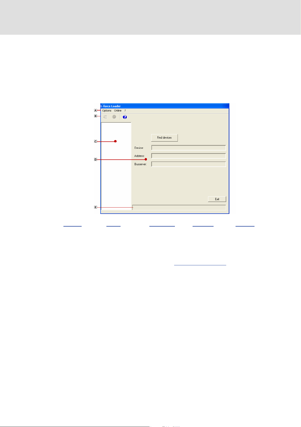
The user interface contains the following control and function elements:
Menu bar Toolbar Function area Dialog area Status bar
O Tip!
The »L-force Loader« can also be script-controlled to automatically download data
to several target systems without the necessity of additional user inputs. For more
information, please refer to the chapter "Control via script files
4.1 Language selection
It is possible to change the language for the menu, dialog and help texts of the user
interface.
r You can choose between German, English and French.
M For changing to another language, select OptionsLanguage and choose the
desired language.
". (C 29)
10 DMS 4.0 EN - 07/2007 L
Page 11

4.2 Menu bar
The menu bar is used to access the menu commands for the »L-force Loader«.
r A click on an item of the main menu opens the corresponding menu and lists the menu
items contained in it.
r Click a menu item to execute the corresponding function.
– Menu items which are displayed in light grey are currently deactivated because the
execution of the corresponding function would not make any sense in the current
program state.
"Options" menu
The Options menu provides commands for the configuration of the »L-force Loader«:
Command Function
System bus configurator... Starts the Lenze system bus configurator
Diagnostics configurator... Starts the Lenze diagnostics configurator
LECOM configurator... Starts the Lenze LECOM configurator
DriveServer configurator... Starts the Lenze DriveServer configurator
IP address... Specifies the IP address
Activation of safety scan A safety scan is made before every action.
Activation of all notes Repeated note display can be stopped by activating the Do not display this note
Language Selection of the language for the user interface.
L-force Loader
User interface
Menu bar
• Use the system bus configurator to easily configure the communication
parameters of the Lenze PC system bus adapters connected to your PC.
• For safety reasons, all »L-force Loader« functions/menu commands are
deactivated while the system bus configurator is running.
• For detailed information on the system bus configurator, please refer to the
Online Help for the system bus configurator.
• Use the diagnostics configurator to easily configure the communication
parameters of the Lenze PC diagnostic adapters connected to your PC.
• For safety reasons, all »L-force Loader« functions/menu commands are
deactivated while the diagnostics configurator is running.
• For safety reasons, all »L-force Loader« functions/menu commands are
deactivated while the LECOM configurator is running.
• For detailed information on the LECOM configurator, please refer to the
DriveServer documentation.
• For safety reasons, all »L-force Loader« functions/menu commands are
deactivated while the DriveServer configurator is running.
• For detailed information on the DriveServer configurator, please refer to the
DriveServer documentation.
• Only required for the "L-force 9400 Servo Drives" series if communication with
the controller is to take place via Ethernet NRT.
• If this option is activated, a tick appears next to the menu command.
again checkbox in the note dialog box.
Use the command Activation of all notes to reset all settings made, i.e. all notes will
be displayed again.
L DMS 4.0 EN - 07/2007 11
Page 12
L-force Loader
User interface
Menu bar
"Online" menu
The Online menu provides commands which can only be activated when the »L-force
Loader« is in online mode:
Command Function
PLC / application start Starts the PLC program/application on the target system
PLC / application stop Stops the PLC program/application on the target system
Controller enable Enables the target system
Controller inhibit Inhibits the target system
• Only with target systems with appropriate functionality
(e.g. 9400 HighLine/StateLine, 9300 Servo PLC, Drive PLC).
• Only with target systems with appropriate functionality
(e.g. 9400 HighLine/StateLine, 9300 Servo PLC, Drive PLC).
• Only with target systems supporting this functionality
(e.g. 9400 HighLine/StateLine, 9300 Servo PLC, Drive PLC).
• Only with target systems supporting this functionality
(e.g. 9400 HighLine/StateLine, 9300 Servo PLC, Drive PLC).
"?" menu
The ? menu provides commands for the activation of the Online Help, the download of
relevant pages from the Internet
Command Function
Help topics Opens the Online Help for the »L-force Loader«
Web support (AKB) Opens the corresponding topic areas of the Lenze Application Knowledge Base (AKB)
Search in AKB
Subscribe newsletter
Software download
Lenze homepage Opens the Lenze homepage on the Internet
About... Displays information about the »L-force Loader« (e.g. version and copyright)
on the Internet
• Internet address (URL): http://www.Lenze.de/akb
• Internet address (URL): http://www.Lenze.de
and the display of program information:
12 DMS 4.0 EN - 07/2007 L
Page 13
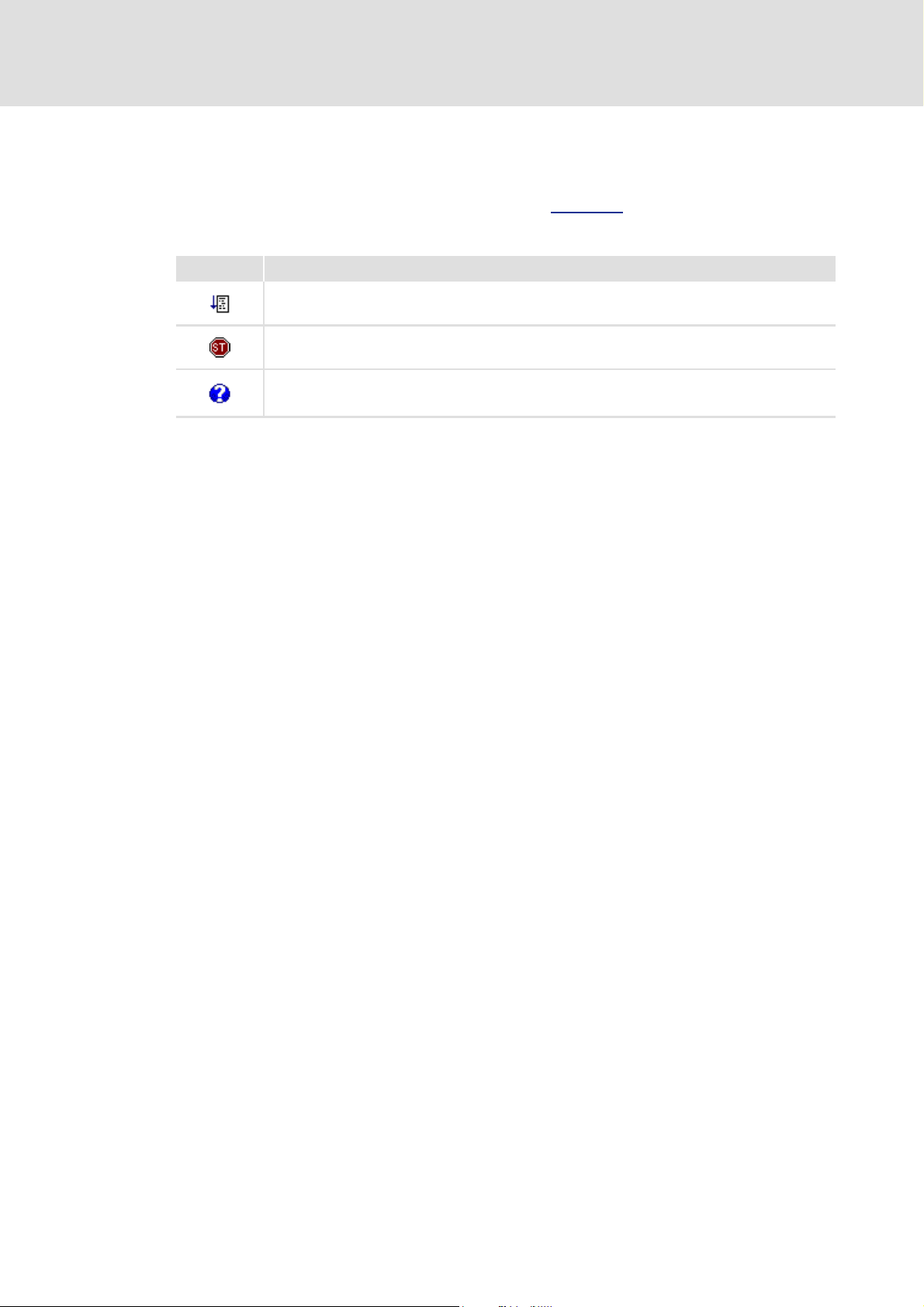
4.3 Toolbar
Via the icons of the toolbar you can directly execute some of the most frequently used
menu commands without making a detour via the
r Simply click an icon to activate the corresponding command.
Icon Function
O Tip!
L-force Loader
User interface
Toolbar
Menu bar.
Starts the PLC program/application
Stops the PLC program/application
Displays help topics
If you position the mouse pointer for a short time over an icon, a "tool tip" will be
displayed with information about the corresponding function.
4.4 Function area
The function area shows all presently available functions in form of icons. The functions
can be activated by a mouse click.
4.5 Dialog area
The dialog area displays input dialogs, buttons and text fields with additional information
about the active function.
4.6 Status bar
The status bar indicates the communication status (online/offline) and the device address.
r For Lenze PLCs, the PLC program status is indicated as well.
r For L-force 9400 Servo Drives, the application status is indicated as well.
L DMS 4.0 EN - 07/2007 13
Page 14

L-force Loader
Operation
How to configure the communication settings
5Operation
5.1 How to configure the communication settings
The Lenze DriveServer and the OPC bus server for the corresponding fieldbus are used to
build up the connection with the target system.
Note!
For the configuration of the communication settings, the DriveServer must be
closed.
The DriveServer is default set to the OPC bus server for the system bus (CAN).
• If you want to use a different OPC bus server for communication, use the
DriveServer configurator to add this bus server to the DriveServer.
DriveServer
For the configuration of the DriveServer, the DriveServer configurator of the »L-force
Loader« is used. The DriveServer configurator is activated via OptionsDriveServer
configurator....
O Tip!
OPC bus server for system bus (CAN)
For the configuration of the system bus (CAN) communication settings, the system bus
configurator of the »L-force Loader« is used. The system bus configurator is activated via
OptionsSystem bus configurator....
For detailed information on the DriveServer, please refer to the DriveServer
documentation.
O Tip!
The diagnostics function of the system bus configurator can, for instance, be used
to check that the PC system bus adapter is working properly.
For detailed information on the system bus configurator, please refer to the CAN
Communication Manual and to the Online Help of the system bus configurator.
14 DMS 4.0 EN - 07/2007 L
Page 15

L-force Loader
Operation
How to configure the communication settings
OPC bus server for LECOM
Instead of using the system bus (CAN), you can also communicate with the target system
via LECOM. The corresponding communication settings are configured with the LECOM
configurator of the »L-force Loader«. The LECOM configurator is activated via
OptionsLECOM configurator....
Example: Configuring a point-to-point connection via LECOM (C 16)
Note!
LECOM does not support the parameter set transfer variant "Replacement
device".
O Tip!
For communication via the serial interface COM1, use the configuration file
"Default_COM1.lccfg" which is set by default in the LECOM configurator.
For detailed information on the LECOM configurator, please refer to the
DriveServer documentation.
Use of the diagnostics interface or Ethernet NRT on L-force 9400 Servo Drives
Instead of using the system bus (CAN), you can also communicate with the controllers of
the "L-force 9400 Servo Drives" series via the diagnostics interface
r The communication settings for the diagnostic adapter are configured with the
diagnostics configurator of the »L-force Loader«. The diagnostics configurator is
activated via OptionsDiagnostics configurator....
r If you want to use Ethernet NRT for communication, open the IP address dialog box via
OptionsIP address... and enter the IP address of the controller.
Use of other OPC bus servers
For communication with the target system, you can also install other bus servers for the
DriveServer. For detailed information on this topic, please refer to the DriveServer
documentation.
X6 or Ethernet NRT.
Note!
Please note that some fieldbuses or OPC bus servers do not support all download
options. Programs and *.lc9 files can, for instance, only be downloaded with the
bus server for the Lenze OPC system bus or other CANopen bus servers.
L DMS 4.0 EN - 07/2007 15
Page 16

L-force Loader
Operation
How to configure the communication settings
5.1.1 Example: Configuring a point-to-point connection via LECOM
Note!
The configuration described below only has to be carried out once.
M How to configure a point-to-point connection via LECOM:
1. Select ProgramsLenzeL-force Loader - 4.0L-force Loader from the Start menu
to start the »L-force Loader«.
In the »L-force Loader«:
2. Select OptionsDriveServer configurator to open the »DriveServer configurator«.
In the »DriveServer configurator«:
3. Select FileConnect to build up a connection to the selected DriveServer.
• Wait until the Please wait dialog disappears and the connection to the
DriveServer has been built up.
4. Select ConfigurationBus server to open the Bus server configuration dialog box.
• The right list field lists all bus servers which have been assigned to the
DriveServer.
• To remove an assignment, select the corresponding bus server from the right
list field and click the Delete button.
5. Click Refresh to list all bus servers available on the selected PC in the left list field.
6. For LECOM, select "Lenze OPC LECOM server" from the left list field and click Add to
assign this bus server to the DriveServer.
• If necessary, repeat the above steps to assign further bus servers to the Drive
Server.
7. Click OK to accept the settings and close the Bus server configuration dialog box.
• The bus servers assigned to the DriveServer will be listed in the name area under
the "Online" element.
8. Select FileDisconnect to end the connection to the selected DriveServer.
9. Select FileExit to exit the »DriveServer configurator«.
16 DMS 4.0 EN - 07/2007 L
Page 17

L-force Loader
Operation
How to configure the communication settings
In the »L-force Loader«:
10. Select OptionsLECOM configurator to open the »LECOM configurator«.
In the »LECOM configurator«:
11. Click OK to confirm the Lenze OPC server LECOM info dialog box.
• The configuration saved last will be loaded automatically.
12. Select the configuration entry for the interface (COMx) from the tree/list on the
left.
• Check the interface settings in the Communication port tab (particularly, COM
number and baud rate) and adjust the settings, if necessary.
• For a point-to-point connection via LECOM, mark the Scan at the server's start
option with a tick.
13. Select FileSave to save the configuration.
14. Select FileExit to exit the »LECOM configurator«.
The configuration is now complete and you can start searching for connected
devices in the »L-force Loader«.
L DMS 4.0 EN - 07/2007 17
Page 18

L-force Loader
Operation
How to select a target system
5.2 How to select a target system
For selecting a target system, you can perform an automatic search for devices connected
to the bus system.
M How to perform an automatic search:
1. Click Find devices to find the devices connected to the bus system.
• The progress of scanning will be indicated by a progress bar.
• At the end of scanning, the Select target system dialog box will appear:
2. Select the desired target system from the tree.
3. Click OK to confirm your selection.
• The selection is accepted and the dialog box is closed.
• The selected target system is displayed in the dialog area:
Next steps:
How to build up a connection with the target system (C 19)
18 DMS 4.0 EN - 07/2007 L
Page 19

How to build up a connection with the target system
5.3 How to build up a connection with the target system
M Click Log in in the function area to build up a connection to the selected target
system.
r If the connection has been established successfully, the »L-force Loader« changes from
offline to online mode and the status bar indicates the communication status "Online"
and the device address.
– For Lenze PLCs, the PLC program status is indicated as well.
– For L-force 9400 Servo Drives, the application status is indicated as well.
r If question marks (???) appear in the dialog area after log in, the target system is not
supported by the »L-force Loader«.
r If it is not possible to build up a connection, an error message with an error number will
be displayed. A list of all error numbers and their meanings can be found in the
appendix. Error numbers, causes & remedies
(C 36)
L-force Loader
Operation
Next steps:
How to select files for the download (C 20)
L DMS 4.0 EN - 07/2007 19
Page 20

L-force Loader
Operation
How to select files for the download
5.4 How to select files for the download
After you have established a connection to the target system and the »L-force Loader« is in
online mode, you can select the files to be downloaded to the target system.
A difference is made between:
r DDS binary files created with the Drive PLC Developer Studio
r Application data created e.g. with the Cam Designer
r GDC parameter set files created with Global Drive Control
r L-force 9400 applications created with the L-force Engineer
Note!
The target system determines which files can be selected (opened) for the
download in the »L-force Loader«.
• The function "Open DDS binary file" is, for instance, only available if the target
system has PLC functionality (e.g. 9300 Servo PLC). How to open a DDS
binary file (C 21)
• The function "Open 9400 application" is, however, only available for
controllers of the "L-force 9400 Servo Drives" series. How to open a 9400
application (C 24)
After opening a file, click Download... to download the file to the target system or
(depending on the target system) open further files to be downloaded and download them
one after another to the target system by clicking Download....
r Detailed information about the download can be found in the chapter "How to
download data". (C 25)
20 DMS 4.0 EN - 07/2007 L
Page 21

5.4.1 How to open a DDS binary file
If the target system has PLC functionality (e.g. 9300 Servo PLC and Drive PLC), this function
can be used to open a DDS binary file for the download.
r All binary formats as of Drive PLC Developer Studio (DDS) version 1.0 are supported.
M How to open a DDS binary file...
1. Select DDS binary file... in the function area.
2. Select the desired file in the Open DDS binary file dialog box.
3. Click OK to confirm your selection.
• The selection is accepted and the dialog box is closed.
r If the binary file could be opened properly,
–the Close DDS binary file function will be available instead of the DDS binary file...
function. Use this function to close the binary file.
–the Download... function will be provided to download the file(s) to the target
system.
– the dialog area will display information about the opened binary file in the Binary file
tab.
L-force Loader
Operation
How to select files for the download
r If it is not possible to open the binary file properly, an error message with an error
number will be displayed.Error numbers, causes & remedies
Next steps:
How to open application data (C 22) / How to open a GDC parameter set file (C 23)
or
How to download data (C 25)
(C 36)
L DMS 4.0 EN - 07/2007 21
Page 22

L-force Loader
Operation
How to select files for the download
5.4.2 How to open application data
If the target system supports the download of application data, click Application data... to
open an application data file for the download.
r After this, you can download *.lc9 files containing motion profiles & cam data created
with Cam Designer or *.lc7 files created with GDC to the target system.
r Apart from *.lc9-/*.lc7 files you can open any other files for the download, provided that
they have the file header specified by Lenze.
– Detailed information about the structure of the file header can be found in the
Manual for the 9300 Servo PLC (6.x), chapter "Appendix / Memory / Download of any
data".
M How to open an application data file...
1. Select Application data... in the function area.
2. Select the desired file in the Open application data dialog box.
3. Click OK to confirm your selection.
• The selection is accepted and the dialog box is closed.
r If the application data could be opened properly,
–the Close application data function will be available instead of the Application
data... function. Use this function to close the application data.
–the Download... function will be provided to download the file(s) to the target
system.
–the dialog area will display information about the opened application data in the
Application data tab.
r If it is not possible to open the application data properly, an error message with an error
number will be displayed.Error numbers, causes & remedies
Next steps:
How to open a DDS binary file (C 21) / How to open a GDC parameter set file (C 23)
or
How to download data (C 25)
(C 36)
22 DMS 4.0 EN - 07/2007 L
Page 23

5.4.3 How to open a GDC parameter set file
Click GDC parameter set file... to open a parameter set file created with Global Drive
Control (GDC) for the download.
M How to open a GDC parameter set file...
1. Select the GDC parameter set file... function in the function area.
2. Select the desired file in the Open GDC parameter set file dialog box.
3. Click OK to confirm your selection.
• The selection is accepted and the dialog box is closed.
r If the parameter set file could be opened properly,
–the Close GDC parameter set file function will be available instead of the
GDC parameter set file... function. Use this function to close the parameter set file.
–the Download... function will be provided to download the file(s) to the target
system.
–the dialog area will display information about the opened parameter set file in the
Parameter set file tab.
L-force Loader
Operation
How to select files for the download
r If it is not possible to open the parameter set file properly, an error message with an
error number will be displayed.Error numbers, causes & remedies (C 36)
Next steps:
How to open a DDS binary file (C 21) / How to open application data (C 22)
or
How to download data (C 25)
L DMS 4.0 EN - 07/2007 23
Page 24

L-force Loader
Operation
How to select files for the download
5.4.4 How to open a 9400 application
Click Open 9400 application to open an application created for the "L-force 9400 Servo
Drives" series with the L-force Engineer for the download.
Note!
For the »L-force Loader«, the 9400 application to be opened must be present in
the form of an L-force Loader file (*.lfl). This file contains the application data
required in a compressed manner.
O Tip!
If you want to create an L-force Loader file (*.lfl) with the Engineer, select Export
L-force Loader file... in the project view of the controller's context menu.
• File name and target directory of the L-force Loader file (*.lfl) to be output can be
freely selected.
M How to open an L-force 9400 application...
1. Select the Open 9400 application function in the function area.
2. Select the desired L-force Loader file (*.lfl) in the Open 9400 application dialog box.
3. Click OK to confirm your selection.
r If the 9400 application could be opened properly,
r If it is not possible to open the 9400 application properly, an error message with an
Next steps:
How to download data (C 25)
• The selection is accepted and the dialog box is closed.
–the Close 9400 application function will be available instead of the Open 9400
application function. Use this function to close the 9400 application.
–the Download... function will be provided to download the file(s) to the target
system.
–the dialog area will display information about the opened application in the 9400
application tab.
error number is displayed.Error numbers, causes & remedies
(C 36)
24 DMS 4.0 EN - 07/2007 L
Page 25

5.5 How to download data
As lon g as at l eas t on e fi le h as been opened for the download, the Download... function will
be available in online mode. Use this function to download the selected file(s).
Note!
After selecting the Download... function, the »L-force Loader« changes from
online mode to the so-called download mode. For safety reasons, the program
cannot be closed in download mode.
Please note that the controller must be inhibited in the target system for the
download.
• For target systems with PLC functionality, the PLC program must additionally
be stopped.
• For controllers of the "L-force 9400 Servo Drives" series the application must
be stopped as well.
L-force Loader
Operation
How to download data
If these requirements are not met, a corresponding message will be indicated.
Download sequence
For the download, the following sequence applies:
1. DDS binary files will always be downloaded first.
2. Application data will be downloaded next.
3. GDC parameter set files will be downloaded last.
This sequence does not apply to the controllers of the "L-force 9400 Servo Drives" series
since to them only L-force 9400 applications can be downloaded.
Before downloading a file
The results of the safety checks carried out before a download are listed in a log in the
dialog area.
r The download can only be carried out if all safety checks have been passed successfully.
r If one of the safety checks is not passed, an error number will be displayed in the log.
r Before the download of DDS binary files and application data, it is also checked
whether the data in the target system is newer than or identical with the data to be
downloaded. If necessary, a corresponding message will be indicated and you can
select if the download shall be continued or stopped.
r Parameter sets can be transferred in two different ways.
Parameter set transfer
During the download
The name of the file being downloaded is displayed in the status bar. The progress of the
download is indicated in form of a bar.
r If an error occurs during the download, an error message with an error number will be
displayed.Error numbers, causes & remedies
(C 27)
(C 36)
L DMS 4.0 EN - 07/2007 25
Page 26

L-force Loader
Operation
How to download data
After a successful download
After the download of a DDS binary file or an L-force 9400 application, a dialog box appears
in which you are asked whether the PLC program or the application is to be started in the
target system.
r If the Always start PLC program/application checkbox of this dialog box is ticked, the
PLC program or application will always be started after a download and the query will
not be displayed. The option can be reset via Options
The number of transferred bytes and parameters and the check test results are listed in a
log.
r Click Next >> to download the next file or Cancel to stop the download process and
change back to the online mode.
After all downloads have been completed successfully, click Main menu >> to change from
download mode to online mode.
After a faulty download
Activation of all notes.
The number of transferred bytes and parameters and an error number are listed in a
Error numbers, causes & remedies (C 36)
log.
r Click Main menu >> to change from download mode to online mode and close the
program or start a new download.
Note!
Please note that the data transferred to the target system will be invalid if the
download of a file has not been completed successfully!
26 DMS 4.0 EN - 07/2007 L
Page 27

5.5.1 Parameter set transfer
The function area provides the following functions for the download of GDC parameter set
files:
Command Function
Duplication of parameter set At the parameter set transfer, some codes of the parameter set are not transferred
Replacement device Codes C0009, C0125 and C0058 are also transferred to the target system.
Assignment of device descriptions
The GDC parameter set file includes the codes to be transferred with the corresponding
initialisation values. The parameter set transfer, however, requires additional information
about the code type. This information is generated from the corresponding device
description.
L-force Loader
Operation
How to download data
to the target system. These are, among others:
• C0009 - AIF device address
• C0125 - AIF baud rate
• C0058 - Rotor position
All codes not transferred to the target system are listed in a note dialog before the
parameter set transfer starts.
Note: LECOM does not support the "Replacement device" function!
The »L-force Loader« tries to assign these device descriptions automatically by searching
the directory which has been the source for the parameter set file for the corresponding
device description.
r If a directory does not include the corresponding device description, the search will be
continued in the directories configured via the DriveServer menu commands
ConfigurationPDB paths....
L DMS 4.0 EN - 07/2007 27
Page 28

L-force Loader
Operation
How to end the connection with the target system
5.6 How to end the connection with the target system
After you have logged in on the target system and changed from offline to online mode,
the Log out function will be indicated instead of the Log in function. Use this function to
end the online connection to the target system.
After you have logged out from the target system, the »L-force Loader« will be in offline
mode again and you can build up a connection to another target system.
5.7 How to exit the L-force Loader
M Click Exit to exit the »L-force Loader«.
Note!
For safety reasons, the program cannot be exited while downloading data to a
target system!
28 DMS 4.0 EN - 07/2007 L
Page 29

6 Control via script files
Data can be automatically downloaded to several target systems if the »L-force Loader«
has been started in the so-called batch mode.
r The batch mode processes a script without the need of additional user inputs.
r All »L-force Loader« activities including possibly occurring error messages are listed in
a log file.
Note!
Please note the following special features in batch mode:
• "Note" and "information" messages are not displayed.
• The target system inhibits the controller automatically!
• A PLC program running on the target system is stopped automatically!
L-force Loader
Control via script files
Structure of the script file
6.1 Structure of the script file
Automatic processing is only possible with a script file which determines the actions to be
carried out.
Script files can be created with any ASCII text editor (e.g. Notepad). A script file is divided
into sections. Different keys can be entered for the sections. Therefore they are very similar
to typical Windows INI files.
r Sections are put into square brackets. The following lines list the keys for a specific
section.
r A key consists of a key name followed by an equal sign and a key value.
– Comments can be added, the comment must, however, be separated from the key
value by a semicolon.
– It is not possible to enter more than one key per line.
–Example:
ShowProcessing=1 ;displays progress window
Warning!
If the machine includes several axes, every axis is started directly after download
if StartAfterDownload = 1 is set. This can lead to dangerous situations!
L DMS 4.0 EN - 07/2007 29
Page 30

L-force Loader
Control via script files
Structure of the script file
O Tip!
Communication settings - [COMMUNICATION] section
Key Parameter
Baudrate Baud rate of the system bus in kBaud.
General settings - [COMMON] section
Key Parameter
NumberOfDevices Number of the target systems to be programmed (max. 63).
ShowProcessing Status window display:
MaxNumberOfErrors The latest version no longer supports this entry and ignores it, if necessary (e.g. in older
ExitAfterDownload Automatic stop of »L-force Loader« after the script has been processed:
The script is not tested for correctness before it is being processed, i.e. script
processing does not stop before an error occurs. The error can be analysed and
eliminated using the log file.
• The baud rate selection in the script is optional.
• If the baud rate is not defined in the script, the value set in the system bus
configurator will be used.
0 = Status window not displayed (standard setting).
1 = Status window displayed.
script files).
0 = »L-force Loader« does not stop after processing is completed (standard setting).
1 = »L-force Loader« stops after processing is completed.
30 DMS 4.0 EN - 07/2007 L
Page 31

L-force Loader
Control via script files
Structure of the script file
Target system-dependent settings - [DEVICE...] sections
Every target system must have a [DEVICE???] section. The question marks must be replaced
by consecutive numbers (001
r If you have defined the key NumberOfDevices=3 in the [COMMON] section, the
following three sections must be available:
[DEVICE001], [DEVICE002], [DEVICE003].
r The target systems are processed subsequently, starting with [DEVICE001].
The following settings can be made for every section:
Key Parameter
NodeAddress Designation of the bus server and address of the target system (see following
... NumberOfDevices).
examples).
• The address is displayed in the dialog area in the Busserver field.
Example 1 - communication via system bus
• In the following example, the target system has the CAN node address "11".
• Check also key "SDO"!
NodeAdress=Lenze OPC Systembus Server.11
Example 2 - communication via LECOM
• In the following example, the target system has the LECOM node address "5".
NodeAdress=Lenze OPC Lecom Server.1-5
Example 3 - communication with L-force 9400 Servo Drives via diagnostic adapter
If only one
indicated:
NodeAdress=Lenze OPC Diagnostics Server.0
If several diagnostic adapters are connected to the PC, unambiguous addressing
requires the indication of the diagnostic adapter's serial number.
• The serial number (S/N) is printed on the diagnostic adapter.
• The serial number can also be displayed in the diagnostics configurator. For this
purpose, select the diagnostic adapter in the configurator and click Diagnostics
on the Common tab.
• In the following example, the diagnostic adapter has the serial number
"00001628".
NodeAdress=Lenze OPC Diagnostics Server.1-1628
Example 4 - communication with 9400 Servo Drives via Ethernet NRT
• In the following example, the OPC Ethernet server has the default address "1".
• The IP address is specified with the "IP" key.
NodeAddress=Lenze OPC Ethernet Server.1
IP IP address
• Only required for communication with 9400 Servo Drives via Ethernet NRT.
• The dots of the IP address must be replaced by underline characters.
Example:
diagnostic adapter is connected to the PC, the default address "0" is to be
IP=172_31_201_38
SDO Parameter channel (1 or 2) for communication.
• Only required for communication via system bus (CAN).
• For a better performance, select the same parameter channel for all devices in the
script file.
• If "0" is set, there is no division into channels and the entire node address range
is accepted.
L DMS 4.0 EN - 07/2007 31
Page 32

L-force Loader
Control via script files
Structure of the script file
Key Parameter
BinFile Path and file name of the DDS binary file for the download.
AddDataFile Path and file name of the application data for the download.
ParameterSetFile Path and file name of the GDC parameter set file for the download.
ApplicationFileSet Path and file name of the L-force Loader file (*.lfl) for the download.
DuplicateParameterSet Determines whether a parameter set is to be duplicated or whether the target
StartAfterDownload Determines whether the PLC program/L-force 9400 application is to be started after
• Not indicated for target systems without PLC functionality.
• File indication is optional (only indicated files will be transferred to the target
system).
• Not indicated for target systems which do not support the download of
application data.
• File indication is optional (only indicated files will be transferred to the target
system).
• File indication is optional (only indicated files will be transferred to the target
system).
• Only required for controllers of the "L-force 9400 Servo Drives" series.
system is a replacement device:
0 = Target system is a replacement device (standard setting).
1 = Parameter set is duplicated.
Note:
• LECOM does not support the "Replacement device" function!
• This key is not evaluated for controllers of the "L-force 9400 Servo Drives" series.
Here the decision about which parameters are to be transferred is already made
in the Engineer at the export of the download data.
download and parameter set transfer have been completed:
0 = PLC program/application not started (standard setting).
1 = PLC program/application started.
32 DMS 4.0 EN - 07/2007 L
Page 33

6.2 Example of a script file
The following example shows a script file for two target systems:
[COMMUNICATION]
Baudrate=500 ; setting optional
[COMMON]
NumberOfDevices=2
ShowProcessing=1 ; 0 = no progress window
; 1 = displays progress window
ExitAfterDownload=0 ; 0 = L-force Loader will not exit
; 1 = L-force Loader will exit after job is done
[DEVICE001]
NodeAddress=Lenze OPC Systembus Server.6
SDO=1
BinFile=D:\Projects\ServoPLC10.BIN
AddDataFile=D:\Projects\CamData10.lc9
ParameterSetFile=D:\Projects\ParSet10.GDC
DuplicateParameterSet=0 ; 0 = to replace a device
; 1 = to duplicate a device
StartAfterDownload=1 ; 0 = plc program will not start
; 1 = plc program will start
; after download
[DEVICE002]
NodeAddress=Lenze OPC Lecom Server.1-1
BinFile= ; no program transfer
AddDataFile=
ParameterSetFile=D:\Projects\ParSet14.GDC
DuplicateParameterSet=1
StartAfterDownload=0
L-force Loader
Control via script files
Example of a script file
L DMS 4.0 EN - 07/2007 33
Page 34

L-force Loader
Control via script files
Syntax of the command line call
6.3 Syntax of the command line call
Use the following syntax to start the »L-force Loader« in batch mode:
Lforce_Loader.exe /batch script file [log file]
r The /batch parameter determines that all background program functions will be script-
controlled.
r The script file parameter indicates the script file to be used.
– It is possible to use absolute and relative path names. A relative path always refers
to the current directory.
r The log file parameter is optional. It contains the name of the log file in which all
activities and possibly occurring error messages will be recorded.Log files
– If you do not enter a path for the log file, the log file will be saved in the same
directory as the script file.
– If you skip the log file parameter, L-force Loader does not create a log file.
(C 40)
Example:
Lforce_Loader.exe /batch MyScript.cmd MyLogfile.txt
34 DMS 4.0 EN - 07/2007 L
Page 35

6.4 Batch mode commands
After the »L-force Loader« has been started in batch mode, the task bar in the info area
displays the following icon:
r Right-click the icon to open a pop-up menu which provides the following commands:
Menu command Function
Indicate processing Shows status window providing information about the progress of script processing.
About... Displays information about the »L-force Loader« (e.g. version and copyright).
Close application Closes the »L-force Loader«.
Cancel Stops download.
L-force Loader
Control via script files
Batch mode commands
• The status window corresponds to the log file except for the “Id" column.
• Activated options are marked with a tick in front of the menu command.
• This command is not available in download mode.
• This command is only available in download mode.
O Tip!
If you position the mouse pointer for a short time over the icon in the task bar,
you will get information about the program status (application name, currently
processed target system, number of errors, name of the file currently
transferred) in form of a tool tip.
The icon in the task bar is animated as long as data is downloaded.
L DMS 4.0 EN - 07/2007 35
Page 36

L-force Loader
Appendix
Error numbers, causes & remedies
7 Appendix
7.1 Error numbers, causes & remedies
Error number Cause Remedy
0001h ...
BFFFh
C000h Error while opening/closing a file. Close the program and restart it. If the
C001h Internal program error (invalid handling). Restart the program. If the problem still
C100h Error while reading the GDC parameter set
Faulty GDC parameter set file:
C101h Error in section "ParamSet". Create a new GDC parameter set file with
C102h Section "ParamSet" is missing.
C103h UserInfo cannot be read.
C104h PDB-ID cannot be read.
C105h Target system name cannot be read.
C106h Variable version cannot be read.
C200h A code specified in the parameter set file
The Online Help for the system bus configurator provides information about these error
numbers.
file.
cannot be found in the device description.
Faulty GDC device description:
C201h Error in section "DefaultParamTypes". If the device description has been created
C202h Section "ParamSet" is missing.
C203h PDB cannot be read.
C204h PDB-ID cannot be read.
C205h Name of ParamSet cannot be read.
C206h SWID_B cannot be read.
C207h Name of ParamSet is unknown.
problem still occurs, check the path and the
file name of the file causing the error.
occurs, contact the Lenze Hotline.
Try to reload the file. If the problem still
occurs, the GDC parameter set file is not
valid. Create a new file with GDC.
GDC.
If the device description has been assigned
manually, ensure that the device description
corresponds to the parameter set file.
with DDS, create a new file. If the problem
still occurs, contact the Lenze Hotline.
36 DMS 4.0 EN - 07/2007 L
Page 37

L-force Loader
Appendix
Error numbers, causes & remedies
Error number Cause Remedy
C300h Error while downloading the DDS binary file. Repeat the download.
If the problem still occurs, contact the Lenze
Hotline.
C301h The target system found on the bus does not
correspond to the target system for which
the DDS binary file has been created.
C302h The project on the target system is a newer
version than the project to be loaded.
C303h Downloading of the DDS binary file has been
cancelled.
C304h Internal program error
(PLC program buffer cannot be created.)
C400h The device description assigned to the GDC
parameter set file cannot be found.
C401h Internal program error.
(Transfer list not yet created.)
C402h The maximum permissible number of errors
has been exceeded during the parameter
transfer.
C403h The preparations for the parameter transfer
have failed.
C404h The device description does not correspond
to the target system found on the bus.
C405h Internal program error.
(Transfer list cannot be created.)
C406h The "pdb.ini" file cannot be read. Check that the "pdb.ini" file is in the »L-force
C407h The GDC parameter set file has been created
for a newer device version than that found
on the bus.
C500h Faulty script file (communication parameters
cannot be read).
C501h Error while creating the log file. Check the log file name entered in the
C502h Error while opening the script file. Check the script file name entered in the
C503h Error while opening the DDS binary file. Check the name of the target system causing
C504h Error while opening the GDC parameter set
file.
C600h No connection to the target system. Check the wiring between PC and target
C601h The target system cannot be identified. Contact the Lenze Hotline.
Check the device address or select a different
DDS binary file.
Repeat the download.
If the problem still occurs, contact the Lenze
Hotline.
Restart the program.
If the problem still occurs, contact the Lenze
Hotline.
Check the settings for the GDC search path in
the initialisation file (key "SearchPathPDB").
If the problem still occurs, contact the person
who created the GDC parameter set file.
Restart the program.
If the problem still occurs, contact the Lenze
Hotline.
Repeat the parameter transfer.
If necessary, increase the number of
permissible errors in the initialisation file
(key "MaxTransferErrors").
Restart the program.
If the problem still occurs, contact the Lenze
Hotline.
Check the device address. If the device
description has been loaded manually, select
a different device description. Otherwise,
select a different GDC parameter set file.
Restart the program.
If the problem still occurs, contact the Lenze
Hotline.
Loader« program directory. If you cannot find
it in the directory, reinstall the »L-force
Loader«.
Create a new GDC parameter set file for the
device version present on the bus.
Check the script file, especially the
[Communication] section.
command line and try again.
command line and try again.
the error (e.g. "DEVICE001") in the log file and
the specifications in the script file.
system.
Restart the program.
L DMS 4.0 EN - 07/2007 37
Page 38

L-force Loader
Appendix
Error numbers, causes & remedies
Error number Cause Remedy
C602h Error while identifying the FIF.
C603h Error while identifying the FIF.
C604h Error while copying the application data. Check the name of the target system causing
C605h Application data of file and target system is
C606h Application data cannot be transferred. Repeat the download.
C607h Error while opening the application data. Check the name of the target system causing
C608h No target system selected. Check whether a target system has been
C60Ah Internal program error: OPC item cannot be
C60Bh Internal program error: OPC item cannot be
C60Ch Internal program error: OPC item cannot be
C60Dh Internal program error: OPC control. Restart PC.
C60Eh Error while reading a file. Check the path of the parameter file.
Communication and download errors
D100h Error during the start of the "OPC Ctl"
D101h No connection to the OPC server. Check that the OPC server has been installed
D102h OPC server is not in status "Running". Restart PC.
D103h Error while creating an OPC item. Reinstall »L-force Loader«.
D104h Error while downloading. The error message contains causes and
D105h Error while connecting to the OPC server. Restart PC / reinstall »L-force Loader«.
D106h Error while disconnecting from the OPC
(Product code cannot be read.)
(ID cannot be read.)
identical.
created.
read.
written.
component.
• Component has not been installed or has
not been correctly registered.
server.
Check the communication parameters.
If the problem still occurs, contact the Lenze
Hotline.
the error (e.g. "DEVICE001") in the log file and
the specifications in the script file.
Only status message, no remedy required.
If the problem still occurs, contact the Lenze
Hotline.
the error (e.g. "DEVICE001") in the log file and
the specifications in the script file.
selected.
Restart »L-force Loader«.
If necessary, restart PC.
Restart »L-force Loader«.
Check whether the target system can be
addressed.
Reinstall »L-force Loader«.
If the problem still occurs, contact Lenze.
Reinstall »L-force Loader«.
Reinstall »L-force Loader«.
correctly.
Reinstall »L-force Loader«.
information about troubleshooting.
Restart PC / reinstall »L-force Loader«.
38 DMS 4.0 EN - 07/2007 L
Page 39

L-force Loader
Appendix
Error numbers, causes & remedies
Error number Cause Remedy
Error while downloading L-force 9400 application
8000C702h Controller inhibit has not been set. Set controller inhibit on the target system.
8000C704h Application has not been stopped. Stop the application on the target system.
8000C801h Error message of target system while
8000C807h Error message of target system:
8000C808h Error message of target system:
8000C809h Error message of target system:
8000C80Ah
8000C8xxh Other (not yet listed) error messages of the
Errors within the DriveServer
E7C18000h Error during download preparations. Repeat download.
E7C18001h PLC has not been stopped. Stop the PLC program on the target system.
E7C18002h Controller inhibit has not been set. Set controller inhibit on the target system.
E7C18003h Incorrect file type (no LC9 file). Create new LC9 file.
E7C18004h Checksum test is negative (incorrect
E7C18005h Item can momentarily not be accessed due to
E7C18006h Target system is momentarily busy copying
E7C18007h Error occurred after the download. Repeat download.
E7C18008h Error after version comparison during
E7C18009h "Cam" template is not available on the target
downloading.
Licence level does not correspond.
Target does not correspond.
Error while configuring the module.
target system while downloading.
checksum).
download.
RAM blocks.
download of an LC7 file.
• Different versions in LC7 file and target
system.
system.
Restart target system to establish the "ready
for download" state.
Create the application again using the
Engineer and transfer it to the target system
or update the target system.
Create the application again using the
Engineer and transfer it to the target system.
Repeat download.
Increase time-out time in the system bus
configurator (e.g. to 3 seconds).
Repeat download after a few minutes or
restart your PC.
Start the PLC program on the target system.
Update the operating system for 9300 EK.
Create DDS project based on Cam template
and transfer it into the target system.
L DMS 4.0 EN - 07/2007 39
Page 40

L-force Loader
Appendix
Log files
7.2 Log files
Log files list all important events for documentation and diagnostics purposes. These
events are for instance:
r Program start
r Connection establishment to the target system with the communication parameters
set
r Target system found (name, version, software product code, etc.)
r Download information
r Disconnection
r Program end
O Tip!
The "Lforce_Loader.txt" log file is automatically created by the »L-force Loader«
and new entries are added until the size of the log file exceeds the value
specified in the initialisation file by the key "SizeLogFile".
If the value is exceeded, the system asks whether a log file backup is wanted before
the existing entries of the log file are deleted.
40 DMS 4.0 EN - 07/2007 L
Page 41

Every event saved in the log file contains the following information:
Column Meaning
Id Function index identifying the event:
0001h Program start
0002h Program end
0003h Log in
0004h Log out
0005h Opening of a DDS binary file
0006h Preparation of the DDS binary file for the download
0007h Download of the DDS binary file
0008h Start of the PLC program
0009h Stop of the PLC program
000Ah Opening of a GDC parameter set file
000Bh Opening of a GDC device description
000Ch Reading of the code list from the GDC device description
000Dh Reading of the code initialisation values from the GDC parameter set file
000Eh Parameter set transfer
000Fh Update of the status line
0010h Opening of a script for the batch mode
0011h Processing of the script
0012h Opening of the application data
0013h Preparation of the application data for the download
0014h Download of the application data
0015h Enable of the target system
0016h Inhibition of the target system
0017h Saving of a parameter set with C0003
0018h No valid bus server
0019h Status: PLC program/application started
001Ah Status: PLC program/application stopped
001Bh Status: controller inhibit set
001Ch Status: controller inhibit not set
001Dh Codes not transferred by definition.
001Eh Code not transferred due to errors.
001Fh Saving of profile data (*.lc7) via C0003
0020h Download of application and/or program data
0021h Start of the rescan for extending the PDB search paths
0022h Extension of the registry by a potential PDB search path
0023h Opening of an L-force 9400 application file (*.lfl)
0024h Identification of an L-force 9400 Servo Drive
0025h Transfer of L-force 9400 application data
L-force Loader
Appendix
Log files
L DMS 4.0 EN - 07/2007 41
Page 42

L-force Loader
Appendix
Log files
Column Meaning
Category The following categories are available:
Date and time Time when the event occurred.
Message text Short description of the event.
Error code Error number (if an error occurred).
•Error
•Warning
•Note
•Info
42 DMS 4.0 EN - 07/2007 L
Page 43

7.3 File header for application data
Note!
The file header is not valid for *.lc7 files. *.lc7 files can only be transferred to the
"9300 servo cam profiler" target system.
L-force Loader
Appendix
File header for application data
Name Data type Data length
in bytes
wSizeHeader WORD 2 Length of the header in bytes
wDataType WORD 2 Specification identifier of the data
dwVersion DWORD 4 Data version
dwRealSize DWORD 4 Length of the user data in bytes (without header)
dwTimeStamp DWORD 4 Time stamp of the last data change
wLicenseInfo WORD 2 Reserved for future extensions
wSizeSymbolicName WORD 2 Length of the symbolic file name
achSymbolicName ACH wSize
Symbolic
Name
wCopyToRam WORD 2 Selection whether the data is automatically copied to the
dwReserved DWORD 4 Reserved for future extensions
awSizeAddInfo DWORD 190
Contents
• After the download this information is available under
C2131.
0 ... 10000 Lenze-specific data
> 10000 User data
• After the download this information is available under
C2132.
• After the download this information is available under
C2133.
Character array containing the symbolic file name
• After the download this information is available under
C2130.
application RAM of the PLC after the download, or not.
• Maximum data length = 128 kbytes (RAM blocks 1 & 2)
0 Data is not copied to the application RAM.
1 Data is copied to the application RAM.
2 ... 65535 Reserved
For the interpretation of the header information applies: least-significant byte first:
wSizeHeader = 00 E4 = 228 Bytehex
wDataType = 00 0A = 10 (Cam data)hex
dwVersion =00000001hex
E4 00 0A 00 01 00 00 00 1C FF 00 00
dwRealSize = 00 00 FF 1C = 65308 Bytehex
L DMS 4.0 EN - 07/2007 43
Page 44

L-force Loader
Index
8Index
Numbers
9400 Servo Drives 24
A
After a successful download 26
Application notes 6
Assignment of device descriptions 27
Automatic search 18
B
Batch mode 29
Before downloading a file 25
C
Command line call 34
Communication settings 14, 30
Connection with the target system 8
Conventions used 5
Copyright 2
Copyright information 2
D
Device description 27
Download sequence 25
DriveServer 14
During the download 25
E
E-mail to Lenze 45
Engineer 24
F
Feedback to Lenze 45
Function area 13
G
General settings 30
M
Menu "?" 12
Menu "Online" 12
Menu "Options" 11
Menu bar 11
O
OPC bus server for LECOM 15
OPC bus server for system bus (CAN) 14
Open 9400 application 24
Open L-force application 24
P
PC diagnostic adapter 8
PC system bus adapter 8
S
Safety instructions 6
Script control 29
Script file 29
Software installation 9
Status bar 13
Structure of safety instructions 6
Supported target systems 7
System bus (CAN) 14
T
Target system-dependent settings 31
Target systems 7
Toolbar 13
Trademarks 2
U
Use of other OPC bus servers 15
User interface 7, 10
H
How to select a target system 18
I
Imprint 2
Installation 9
L
Language 10
Language selection 10
Layout of the safety instructions 6
LECOM 15
L-force 9400 Servo Drives 24
Liability 2
44 DMS 4.0 EN - 07/2007 L
Page 45

Your opinion is important to us
&
.
These Instructions were created to the best of our knowledge
and belief to give you the best possible support for handling
our product.
If you have suggestions for improvement, please e-mail us to:
feedback-docu@Lenze.de
Thank you for your support.
Your Lenze documentation team
)(('%$
L 45
 Loading...