

Page 1
LDEDS−CCU210B
.Jf$
Ä.Jf$ä
System Manual
LDEC
LDECBBF1xxxxxxHx
Carriage control systems for monorail overhead conveyors
l
Page 2

0Fig. 0Tab. 0
Page 3

Contents i
1 About this documentation 4 . . . . . . . . . . . . . . . . . . . . . . . . . . . . . . . . . . . . . . . . . . . . . . . . . .
1.1 Document history 4 . . . . . . . . . . . . . . . . . . . . . . . . . . . . . . . . . . . . . . . . . . . . . . . . . . . .
1.2 Conventions used 5 . . . . . . . . . . . . . . . . . . . . . . . . . . . . . . . . . . . . . . . . . . . . . . . . . . . .
1.3 Notes used 6 . . . . . . . . . . . . . . . . . . . . . . . . . . . . . . . . . . . . . . . . . . . . . . . . . . . . . . . . . .
2 Safety instructions 7 . . . . . . . . . . . . . . . . . . . . . . . . . . . . . . . . . . . . . . . . . . . . . . . . . . . . . . . . .
2.1 General safety and application notes for Lenze control systems 7 . . . . . . . . . . . . . .
2.2 Residual hazards 10 . . . . . . . . . . . . . . . . . . . . . . . . . . . . . . . . . . . . . . . . . . . . . . . . . . . . .
3 Device description 11 . . . . . . . . . . . . . . . . . . . . . . . . . . . . . . . . . . . . . . . . . . . . . . . . . . . . . . . .
3.1 Device features 11 . . . . . . . . . . . . . . . . . . . . . . . . . . . . . . . . . . . . . . . . . . . . . . . . . . . . . .
3.2 Overview 12 . . . . . . . . . . . . . . . . . . . . . . . . . . . . . . . . . . . . . . . . . . . . . . . . . . . . . . . . . . . .
3.3 Type code 15 . . . . . . . . . . . . . . . . . . . . . . . . . . . . . . . . . . . . . . . . . . . . . . . . . . . . . . . . . .
4 Technical data 18 . . . . . . . . . . . . . . . . . . . . . . . . . . . . . . . . . . . . . . . . . . . . . . . . . . . . . . . . . . . .
4.1 General data and operating conditions 18 . . . . . . . . . . . . . . . . . . . . . . . . . . . . . . . . . .
4.2 Rated data 20 . . . . . . . . . . . . . . . . . . . . . . . . . . . . . . . . . . . . . . . . . . . . . . . . . . . . . . . . . .
5 Mechanical installation 22 . . . . . . . . . . . . . . . . . . . . . . . . . . . . . . . . . . . . . . . . . . . . . . . . . . . . .
5.1 Important notes 22 . . . . . . . . . . . . . . . . . . . . . . . . . . . . . . . . . . . . . . . . . . . . . . . . . . . . . .
5.2 Dimensions 23 . . . . . . . . . . . . . . . . . . . . . . . . . . . . . . . . . . . . . . . . . . . . . . . . . . . . . . . . . .
6 Electrical installation 26 . . . . . . . . . . . . . . . . . . . . . . . . . . . . . . . . . . . . . . . . . . . . . . . . . . . . . . .
6.1 Important notes 26 . . . . . . . . . . . . . . . . . . . . . . . . . . . . . . . . . . . . . . . . . . . . . . . . . . . . . .
6.2 Basic circuit diagram 28 . . . . . . . . . . . . . . . . . . . . . . . . . . . . . . . . . . . . . . . . . . . . . . . . . .
6.3 Mains connection 30 . . . . . . . . . . . . . . . . . . . . . . . . . . . . . . . . . . . . . . . . . . . . . . . . . . . .
6.4 Motor connection 31 . . . . . . . . . . . . . . . . . . . . . . . . . . . . . . . . . . . . . . . . . . . . . . . . . . .
6.5 Control terminals 32 . . . . . . . . . . . . . . . . . . . . . . . . . . . . . . . . . . . . . . . . . . . . . . . . . . . . .
6.6 Connection of system bus (CAN) 35 . . . . . . . . . . . . . . . . . . . . . . . . . . . . . . . . . . . . . . . .
7 Commissioning 37 . . . . . . . . . . . . . . . . . . . . . . . . . . . . . . . . . . . . . . . . . . . . . . . . . . . . . . . . . . .
7.1 Before switching on 37 . . . . . . . . . . . . . . . . . . . . . . . . . . . . . . . . . . . . . . . . . . . . . . . . . .
7.2 Switch−on sequence 38 . . . . . . . . . . . . . . . . . . . . . . . . . . . . . . . . . . . . . . . . . . . . . . . . . .
8 Function library 39 . . . . . . . . . . . . . . . . . . . . . . . . . . . . . . . . . . . . . . . . . . . . . . . . . . . . . . . . . . .
8.1 Important notes 39 . . . . . . . . . . . . . . . . . . . . . . . . . . . . . . . . . . . . . . . . . . . . . . . . . . . . . .
8.2 Operating mode 40 . . . . . . . . . . . . . . . . . . . . . . . . . . . . . . . . . . . . . . . . . . . . . . . . . . . . .
8.3 Digital input signals 41 . . . . . . . . . . . . . . . . . . . . . . . . . . . . . . . . . . . . . . . . . . . . . . . . . .
8.3.1 Description 41 . . . . . . . . . . . . . . . . . . . . . . . . . . . . . . . . . . . . . . . . . . . . . . . . . .
8.3.2 Connection logic 43 . . . . . . . . . . . . . . . . . . . . . . . . . . . . . . . . . . . . . . . . . . . . . .
8.3.3 Assignment logic 45 . . . . . . . . . . . . . . . . . . . . . . . . . . . . . . . . . . . . . . . . . . . . .
LDEDS−CCU210B EN 4.0
l 3
Page 4

Contentsi
8.4 Digital output signals 48 . . . . . . . . . . . . . . . . . . . . . . . . . . . . . . . . . . . . . . . . . . . . . . . . .
8.4.1 Description 48 . . . . . . . . . . . . . . . . . . . . . . . . . . . . . . . . . . . . . . . . . . . . . . . . . .
8.4.2 Assignment logic 49 . . . . . . . . . . . . . . . . . . . . . . . . . . . . . . . . . . . . . . . . . . . . .
8.5 Motor control 51 . . . . . . . . . . . . . . . . . . . . . . . . . . . . . . . . . . . . . . . . . . . . . . . . . . . . . . . .
8.5.1 "Motor speed V1−V8" function 51 . . . . . . . . . . . . . . . . . . . . . . . . . . . . . . . . . .
8.5.2 Stop functions 53 . . . . . . . . . . . . . . . . . . . . . . . . . . . . . . . . . . . . . . . . . . . . . . .
8.5.3 "Frequency limitation" function (speed limit) 54 . . . . . . . . . . . . . . . . . . . . .
8.5.4 "Open brake" function 55 . . . . . . . . . . . . . . . . . . . . . . . . . . . . . . . . . . . . . . . . .
8.6 Monitoring 56 . . . . . . . . . . . . . . . . . . . . . . . . . . . . . . . . . . . . . . . . . . . . . . . . . . . . . . . . . .
8.6.1 Anti−collision sensor SensoPart 56 . . . . . . . . . . . . . . . . . . . . . . . . . . . . . . . . . .
8.6.2 I2t monitoring 60 . . . . . . . . . . . . . . . . . . . . . . . . . . . . . . . . . . . . . . . . . . . . . . . .
8.6.3 Non−equivalence monitoring 62 . . . . . . . . . . . . . . . . . . . . . . . . . . . . . . . . . . .
8.6.4 Motor temperature monitoring 63 . . . . . . . . . . . . . . . . . . . . . . . . . . . . . . . . .
8.6.5 Output stage temperature monitoring 63 . . . . . . . . . . . . . . . . . . . . . . . . . . .
8.6.6 Parameter error 63 . . . . . . . . . . . . . . . . . . . . . . . . . . . . . . . . . . . . . . . . . . . . . .
8.6.7 External error 63 . . . . . . . . . . . . . . . . . . . . . . . . . . . . . . . . . . . . . . . . . . . . . . . .
8.7 Infrared data transmission (IrDA) 64 . . . . . . . . . . . . . . . . . . . . . . . . . . . . . . . . . . . . . . .
8.8 IrDA positioning 65 . . . . . . . . . . . . . . . . . . . . . . . . . . . . . . . . . . . . . . . . . . . . . . . . . . . . . .
8.9 Infrared remote control (IrRC) 67 . . . . . . . . . . . . . . . . . . . . . . . . . . . . . . . . . . . . . . . . . .
8.10 Half Wave Code (HWC) 69 . . . . . . . . . . . . . . . . . . . . . . . . . . . . . . . . . . . . . . . . . . . . . . . .
8.11 Open and closed loop control 72 . . . . . . . . . . . . . . . . . . . . . . . . . . . . . . . . . . . . . . . . . . .
8.12 Status messages 74 . . . . . . . . . . . . . . . . . . . . . . . . . . . . . . . . . . . . . . . . . . . . . . . . . . . . .
9 Troubleshooting and fault elimination 77 . . . . . . . . . . . . . . . . . . . . . . . . . . . . . . . . . . . . . . .
9.1 Status display 77 . . . . . . . . . . . . . . . . . . . . . . . . . . . . . . . . . . . . . . . . . . . . . . . . . . . . . . .
9.2 Fault messages 80 . . . . . . . . . . . . . . . . . . . . . . . . . . . . . . . . . . . . . . . . . . . . . . . . . . . . . .
10 Appendix 84 . . . . . . . . . . . . . . . . . . . . . . . . . . . . . . . . . . . . . . . . . . . . . . . . . . . . . . . . . . . . . . . .
10.1 Signal processing − overview 84 . . . . . . . . . . . . . . . . . . . . . . . . . . . . . . . . . . . . . . . . . . .
10.2 Code table 86 . . . . . . . . . . . . . . . . . . . . . . . . . . . . . . . . . . . . . . . . . . . . . . . . . . . . . . . . . .
l 4
LDEDS−CCU210B EN 4.0
Page 5

1 About this documentation
Contents
The System Manual provides full information on the intended use of the carriage control
system for monorail overhead conveyors.
, Information on customised designs can be found in a separate documentation
supplied with the product.
Validity
About this documentation
Document history
1
Type Type designation from hardware
LDEC carriage control LDECBBF1xxxxxxHW − V3.00
LDEC carriage control with
half−wave coding
Target group
This System Manual is directed to all persons dimensioning, installing, commissioning and
adjusting monorail overhead conveyors with carriage control systems.
I Tip!
Information and auxiliary devices related to the Lenze products can be found
in the download area at
http://www.Lenze.com
1.1 Document history
Material number Version Description
13202797 1.0 04/2007 TD00 First edition
13238907 2.0 02/2008 TD03 New product designation
13240731 2.1 03/2008 TD03 UL formulation has been removed from the
13285774 3.0 09/2009 TD03 Description of CAN interface added
version
from software version
LDECBBF1xxxxxxHC − V3.00
specification;
Spark suppressor has been replaced by freewheeling
diode
.Jf$ 4.0 09/2012 TD29 "Function library" chapter extended;
LDEDS−CCU210B EN 4.0
l
"Troubleshooting and fault indications" and "Code
list" chapters revised
5
Page 6

1
About this documentation
Conventions used
1.2 Conventions used
Type of information Identification Examples/notes
Spelling of numbers
Decimal separator
Text
Program name » « PC software
Icons
Page reference ^ Reference to another page with additional
Documentation reference , Reference to another documentation with
language−dependentIn each case, the signs typical for the target
language are used as decimal separators.
For example: 1234.56 or 1234,56
For example: »Engineer«, »Global Drive
Control« (GDC)
information
For instance: ^ 16 = see page 16
additional information
For example: , EDKxxx = see
documentation EDKxxx
6
l
LDEDS−CCU210B EN 4.0
Page 7

About this documentation
Notes used
1
1.3 Notes used
The following pictographs and signal words are used in this documentation to indicate
dangers and important information:
Safety instructions
Structure of safety instructions:
} Danger!
(characterises the type and severity of danger)
Note
(describes the danger and gives information about how to prevent dangerous
situations)
Pictograph and signal word Meaning
{ Danger!
} Danger!
( Stop!
Danger of personal injury through dangerous electrical voltage.
Reference to an imminent danger that may result in death or
serious personal injury if the corresponding measures are not
taken.
Danger of personal injury through a general source of danger.
Reference to an imminent danger that may result in death or
serious personal injury if the corresponding measures are not
taken.
Danger of property damage.
Reference to a possible danger that may result in property
damage if the corresponding measures are not taken.
Application notes
Pictograph and signal word Meaning
) Note!
I Tip!
,
Important note to ensure troublefree operation
Useful tip for simple handling
Reference to another documentation
LDEDS−CCU210B EN 4.0
l
7
Page 8

2
Safety instructions
General safety and application notes for Lenze control systems
2 Safety instructions
2.1 General safety and application notes for Lenze control systems
(in accordance with Low−Voltage Directive 2006/95/EC)
General
Lenze controls can have live, even moving or rotating parts during operation − according
to their enclosure. Surfaces can be hot.
The unauthorised removal of the required cover, improper use, incorrect installation or
operation will risk serious personal injury and damage to property.
Additional information can be found in the documentation.
All work concerning transport, installation, commissioning and maintenance may only be
performed by qualified technical personnel (observe IEC 364 or CENELEC HD 384 or
DIN VDE 0100 and IEC report 664 or DIN VDE 0110 and national regulations for the
prevention of accidents).
Qualified technical personnel within these basic safety instructions are persons who are
familar with installation, assembly, commissioning and operation of the product and who
have the respective qualifications for their work.
The Hardware Manual contains important safety instructions and notes with regard to the
connection and commissioning of the control system, which you have to observe.
Therefore always keep the Hardware Manual near the control system.
The Hardware Manual always has to be complete and in a perfectly readable state.
8
l
LDEDS−CCU210B EN 4.0
Page 9

Safety instructions
General safety and application notes for Lenze control systems
Application as directed
The Lenze control system is designed for operation on a travelling drive (short−time brake
applications permissible only). Without protection of persons (optional) the control
system is not suitable for hoist applications!
Lenze control systems are components intended for installation in electrical systems or
machines. They are not household appliances, but are designed as components exclusively
for application for commercial or professional use according to EN 61000−3−2. The
documentation contains notes for maintaining the limit values to EN 61000−3−2.
If the control systems are installed in machines, commissioning (i.e. starting operation as
directed) is prohibited until it has been determined that the machine corresponds to the
regulations of EC Directive 98/37/EC (Machinery Directive); observe EN 60204.
The commissioning (i.e. starting the intended operation) is only allowed if the EMC
Directive (89/336/EEC) is met.
The Lenze control systems meet the requirements of Low−Voltage Directive 2006/95/EC.
The harmonised standards of the EN 61800−5−1, EN 61800−3, EN 61800−2 series are
applied to the Lenze control systems.
2
Technical data and connection requirement information appear on the nameplate and in
the documentation. They must be observed.
Warning: The control systems are products for the use in a second environment in
accordance with EN 61800−3 (industrial environment). These products can cause radio
interferences in residential areas. In this case it may be required for the operator to
implement corresponding measures.
Transport, storage
Observe the notes for transport, storage and proper handling.
Observe the climatic conditions according to EN 61800−2.
Installation
The control systems must be set up and cooled according to the regulations of the
accompanying documentation.
Ensure careful handling and avoid mechanical overload. Do not bend any components
during transport or handling or change insulation distances. Do not touch any electronic
components or contacts.
Lenze control systems contain electrostatic sensitive components that can easily be
damaged by improper handling. To avoid risks to health, do not damage or destroy any
electrical components!
LDEDS−CCU210B EN 4.0
l
9
Page 10

2
Safety instructions
General safety and application notes for Lenze control systems
Electrical connection
When working on live control systems, observe the applicable national regulations for the
prevention of accidents (e.g. VBG 4 in Germany).
Perform the electrical installation in accordance with applicable regulations (e.g. cable
cross−sections, fusing, PE connections). The documentation contains additional notes.
The documentation contains notes for EMC−compliant installation (shielding, earthing,
arrangement of filters and routing of cables). Also observe these notes for direct control
systems bearing the CE mark. The manufacturer of the system or machine is responsible
for maintaining the limit values required by EMC regulations.
Operation
You may have to fit additional monitoring and protection devices to systems with built−in
Lenze control systems in accordance with relevant safety regulations (e.g. law on technical
equipment, regulations for the prevention of accidents). You may adjust the Lenze control
systems to your application. Observe the notes in the documentation for this purpose.
Keep all protective covers closed during operation.
Service and maintenance
The Lenze control system is maintenance−free, provided that the prescribed operating
conditions are complied with.
Disposal
Send metals and plastics for recycling. Dispose of assembled PCBs properly.
Observe the product−specific safety and application notes in these instructions!
10
l
LDEDS−CCU210B EN 4.0
Page 11

2.2 Residual hazards
Protection of persons
ƒ The X1 power connector contacts (supply via flat connector field) can conduct
hazardous voltages if the control system is connected to the mains. Therefore
disconnect the control system before carrying out any work on it.
ƒ The X2 power connector contacts also conduct hazardous voltages. Depending on the
risk analysis of the machine/system, you may have to take additional protective
measures.
ƒ If the status LEDs and other display elements go out, this does not indicate that the
control system is disconnected from the mains and is deenergised.
ƒ During operation, the control system has to be closed.
ƒ The current collector may only be touched 3 minutes after disconnection from the
mains. Before carrying out any work on the control system, check whether all power
terminals are deenergised. The control system may not be short−circuited.
Safety instructions
Residual hazards
2
ƒ Operation at ambient temperatures > 50 °C:
– The operating temperature of the control system housing is > 60 °C.
– Depending on the risk analysis on the machine/system, you may have to use
additional protective covers.
Motor protection
ƒ The connected motor can overheat if
– motors that do not feature temperature monitoring with PTC thermistor (PTC) or
thermal contact (NC contact) are operated on the control system.
– the temperature monitoring with PTC thermistor (PTC) or thermal contact
(NCcontact) is not connected to the control system
– the temperature monitoring is switched off (C0120 = 0).
– the temperature monitoring is set to "Warning" (C0120 = 2).
LDEDS−CCU210B EN 4.0
l
11
Page 12

3
Device description
Device features
3 Device description
3.1 Device features
Vehicle control system Description
LDECBBF1xxxxxxHW
LDECBBF1xxxxxxHC
0.75/ 1.5/ 2.2 kW
l Travelling drive for monorail overhead conveyors (MOC),
frequency−controlled
l Energy supply 3/PE/PEN AC 360 V − 0 % ... 528 V + 0 %
l Connection of an external data memory to the control system
l Halve wave selection
l Halve wave feedback signal
l Display: 7−segment LED display red for status display, error messages, special
display
12
l
LDEDS−CCU210B EN 4.0
Page 13
Device description
Overview
3
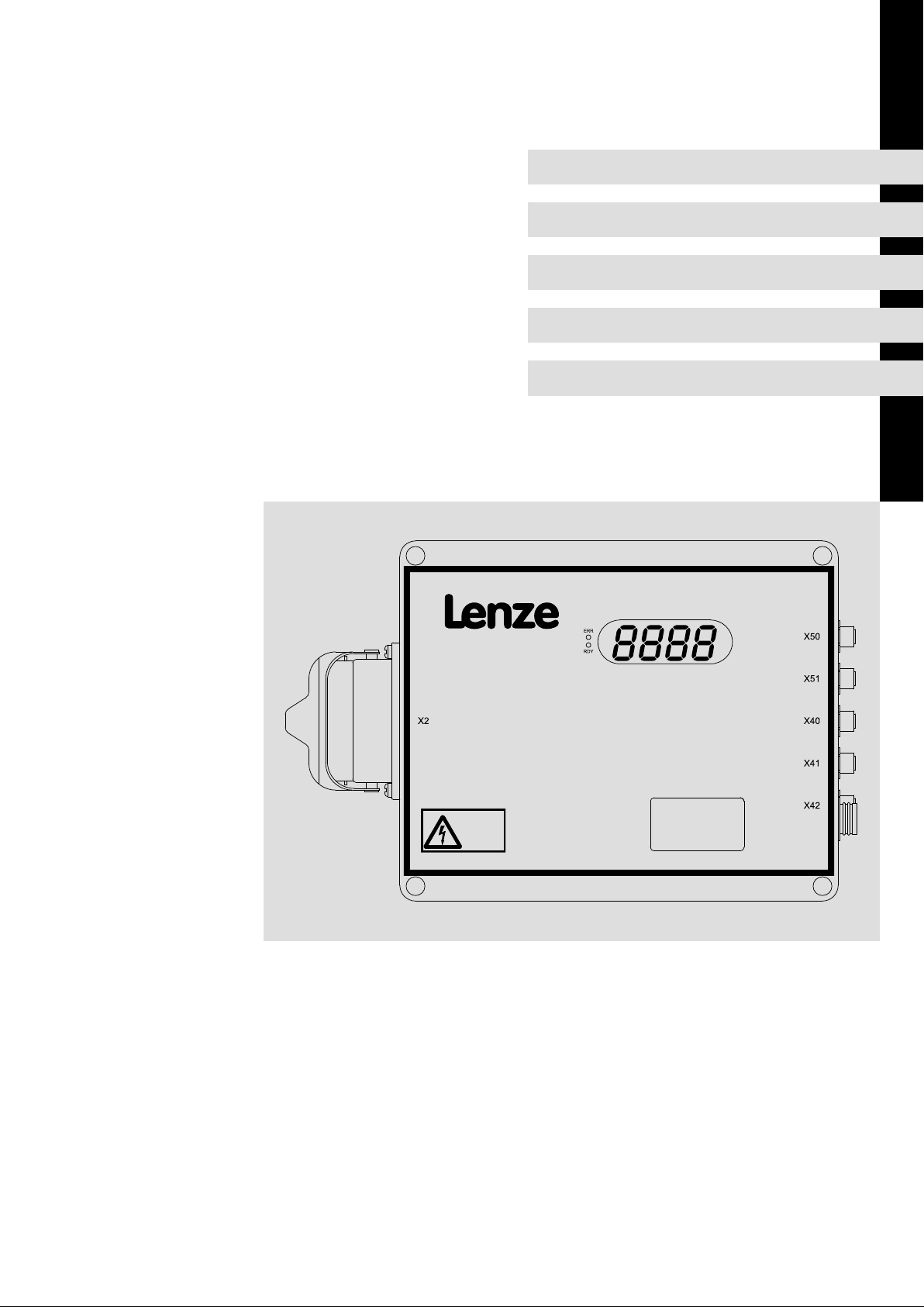
3.2 Overview
Power 0.75 kW
Operational control and connections
Pos. Function Description
0 Important fault messages Short description of the most important fault
1 Status display of device (LED) Readiness for operation, error ^ 78
2
Infrared receiver ...
... for infrared data transmission
(IrDA)
... for infrared remote control (IrRC) Manual operation via infrared remote control ^ 68
3 4−digit 7−segment display Status display, error messages, warning signals ^ 79
4 On/Off switch Software deactivation, acknowledgement of errors
X1 Mains connection Connector: flat connector, 10−pole ^ 31
X2 Motor connection Connector: socket, Harting HAN−10B, 10−pole + PE ^ 32
X43 Digital inputs DIN1/DIN2 Connector: socket, 8−pole, M12 ^ 34
X44 Digital inputs DIN3/DIN4
Digital output DOUT1
X45 Digital inputs DIN5, DIN6
Digital output DOUT2
X50 Connection of external data
memory
X51 Connection of anti−collision sensor Connector: socket, 5−pole, M12, B−coded ^ 33
System bus (CAN) connection
X60
(behind the cover)
X61
messages
Parameter setting, manual operation and status
enquiries via PDA
Connector: socket, 4−pole, M12 ^ 34
Connector: socket, 4−pole, M12 ^ 35
Connector: socket, 8−pole, M12 ^ 33
RJ45 connector ^ 33
^ 81
^ 65
CCU210_002H
LDEDS−CCU210B EN 4.0
l
13
Page 14

3
Device description
Overview
Power 1.5 kW
Operational control and connections
Pos. Function Description
0 Important fault messages Short description of the most important fault
1 Status display of device (LED) Readiness for operation, error ^ 78
2
Infrared receiver ...
... for infrared data transmission
(IrDA)
... for infrared remote control (IrRC) Manual operation via infrared remote control ^ 68
3 4−digit 7−segment display Status display, error messages, warning signals ^ 79
4 On/Off switch Software deactivation, acknowledgement of errors
X1 Mains connection Connector: flat connector, 10−pole ^ 31
X2 Motor connection Connector: socket, Harting HAN−10B, 10−pole + PE ^ 32
X40 Digital inputs DIN3 ... DIN7
Digital output DOUT2
X41 Digital input DIN2
Digital output DOUT1
X42 Digital inputs DIN1, DIN8 Connector: socket, 4−pole, M12 ^ 34
X50 Connection of external data
memory
X51 Connection of anti−collision sensor Connector: socket, 5−pole, M12, B−coded ^ 33
System bus (CAN) connection
X60
(behind the cover)
X61
messages
Parameter setting, manual operation and status
enquiries via PDA
Connector: socket, 8−pole, M12 ^ 33
Connector: socket, 4−pole, M12 ^ 34
Connector: socket, 8−pole, M12 ^ 33
RJ45 connector ^ 33
^ 81
^ 65
CCU210_002A
14
l
LDEDS−CCU210B EN 4.0
Page 15

Power 2.2 kW
Device description
Overview
3
Operational control and connections
Pos. Function Description
0 Important fault messages Short description of the most important fault
1 Status display of device (LED) Readiness for operation, error ^ 78
2
Infrared receiver ...
... for infrared data transmission
(IrDA)
... for infrared remote control (IrRC) Manual operation via infrared remote control ^ 68
3 4−digit 7−segment display Status display, error messages, warning signals ^ 79
4 On/Off switch Software deactivation, acknowledgement of errors
X1 Mains connection Connector: flat connector, 10−pole ^ 31
X2 Motor connection Connector: socket, Harting HAN−10B, 10−pole + PE ^ 32
X40 Digital inputs DIN3 ... DIN7
Digital output DOUT2
X41 Digital input DIN2
Digital output DOUT1
X42 Digital inputs DIN1, DIN8 Connector: socket, 4−pole, M12 ^ 34
X50 Connection of external data
memory
X51 Connection of anti−collision sensor Connector: socket, 5−pole, M12, B−coded ^ 33
System bus (CAN) connection
X60
(behind the cover)
X61
messages
Parameter setting, manual operation and status
enquiries via PDA
Connector: socket, 8−pole, M12 ^ 33
Connector: socket, 4−pole, M12 ^ 34
Connector: socket, 8−pole, M12 ^ 33
RJ45 connector ^ 33
^ 81
^ 65
CCU210_002A
LDEDS−CCU210B EN 4.0
l
15
Page 16

3
Device description
Type code
3.3 Type code
This documentation is valid for LDEC carriage control systems as of nameplate data:
0 Manufacturer code
1 Product family
2 Equipment line
3 Generation
4 Design
5 Number of axes
Nameplate
LDE C B B F 1 xxx xxx Hx NN
Product
Order no.
Type
Input
Output
132341632
Serial No
Hans-Lenze-Strasse 1
D-31855 Aerzen
Material
ED
Brake
%
IP
CCU210_104
1
6 Power of first axis in W
7 Power of second axis in W
8 Communication
9 Power of third axis / variants, customer version
Further information
:
Product designation
; Order number
< Input data of frequency inverter
= Output data of frequency inverter
> Degree of protection
? Operating time in %
@ Brake
16
l
LDEDS−CCU210B EN 4.0
Page 17

Legend for LDECBBF1xxxxxxHW type code
0 Manufacturer code
LDE Lenze
1 Product family
L Local control unit
I Inductive control unit
C Conductive control unit
Z General accessories
2 Equipment line
B Baseline
S Stateline
H Highline
3 Generation
A 1st generation
B 2nd generation
4 Design
F Frequency inverter
M Motor starter
P Pole−changing control system
5 Number of axes
1 1 axis
2 2 axes
3 3 axes
S Special axes
6 Power of first axis in W
xxx e.g.
751= 75 x 10
7 Power of second axis in W
xxx e.g.
123 = 12 x 10
1
W = 750 W
3
W = 12kW
Device description
Type code
3
8 Communication
DB Rail bus
DN DeviceNet IN Inductive
EI Ethernet/IP PB Profibus
EP Ethernet Powerlink PW Powerwave
ER PROFInet RF Radio frequency
ET Ethercat SC Sercos
HC Half wave (HWC=half wave code) WL WLAN
HW Half wave
LDEDS−CCU210B EN 4.0
l
IB Interbus
17
Page 18

3
Device description
Type code
9 Power of third axis / variants, customer version
01 = 0.55kW
02 = 0.75kW
03 = 1.1kW
04 = 2.2kW
05 = 4.0kW
06 = 7.5kW
07 = 10.0kW
AA Labelling (variants_customer version)
Other characters
NN Not relevant
x For the entry of numbers
18
l
LDEDS−CCU210B EN 4.0
Page 19

General data and operating conditions
4 Technical data
4.1 General data and operating conditions
General data
Conformity and approval
Conformity
CE
Protection of persons and equipment
Degree of protection EN 60529
Earth leakage current EN 61800−5−1 < 3.5 mA
Insulation of control
circuits
Insulation resistance EN 61800−5−1
Protective measures Against motor overtemperature (input for PTC or thermal
2006/95/EC Low−Voltage Directive
93/68/EEC EMC Directive (basis 89/336/EEC)
EN 61800−5−1 Safe mains isolation by double (reinforced) insulation
Technical data
IP54
Cover all unused connectors with protective caps or dummy
plugs.
The cover over X60/X61 has to be available.
< 2000 m site altitude: overvoltage category III
> 2000 m site altitude: overvoltage category II
contact), overcurrent at output
4
EMC
Noise emission EN 61800−3
Noise immunity EN 61800−3 Compliance with the limit values for the 2. environment
Compliance with the limit values for the 2. environment
(industrial premises): category C3
(industrial premises): category C3
LDEDS−CCU210B EN 4.0
l
19
Page 20

4
Technical data
General data and operating conditions
Operating conditions
Ambient conditions
Climatic
Storage
Transport IEC/EN 60721−3−2 2K3 (−25 ... +70 °C)
Operation IEC/EN 60721−3−3 3K3 (0...+45 °C)
Pollution EN 61800−5−1 Degree of pollution 2
Site altitude < 4000 m amsl
Mechanic
Vibration resistance
Storage Germanischer Lloyd Vibration test 1
Transport EN 60721−3−2 2M2
Operation
Electric
Mains connection
Mains system
TT, TN
(earthed neutral)
IT Operation permitted without restrictions.
IEC/EN 60721−3−1
EN 60721−3−3 3M4
EN 60721−3−7 7M2
1K3 (−25 ... +70 °C) < 6 months
1K3 (−25 ... +40 °C) > 6 months
> +40 °C: reduce the rated output current by 2.5%/°C.
> 1000 m amsl: reduce the rated output current by
5 %/ 1000 m.
Operation permitted without restrictions.
> 2 years: form DC−bus
capacitors
Motor connection
Length of the motor
cable
Cable type Shielded servo cable (e. g. LAPP: Ölflex servo, FD−755−CP)
Mounting conditions
Mounting place On monorail overhead conveyors
Mounting position Vertically, control connections laterally on the right
Mounting clearances
at the top
at the bottom
to the sides
< 5 m from motor connector
Typically 150 mm
The actual free space is determined by the connectors used
and the cable bending radii.
20
l
LDEDS−CCU210B EN 4.0
Page 21

4.2 Rated data
) Note!
The frequency inverter is not suitable for permanent operation in generator
mode.
Mains voltage
Voltage range U
Frequency f
Fusing 10 A−T/AC 500 V
Frequency inverter (data for operation on 3/PE/PEN AC 400 V, switching frequency 8 kHz)
Starting current
Effektive I
Peak I
Rated power (typical MOC application)
Operating time 70 % PN [kW] 0.75 1.5 −
Operating time 50 % PN [kW] − − 2.2
Typical motor power
4−pole asynchronous motor, Y connection
Max. output power SN [kVA] 1.3 2.0 3.9
Output current
Duration I
For 60 s I
Switching frequency
Optionally f [kHz] 2, 4, 8
Lenze setting f [kHz] 8
Motor output frequency f [Hz] 0 ... 120 variable
Power loss at rated load P
Power loss in idle state (only half wave
power, 24V−sensors are not connected)
DC motor brake control
Brake voltage
Duration (U = UN x 0.45) U [V DC
Peak (U
Max. braking current I [A
Integrated switched−mode power supply (supply for external encoders and actuators)
Output voltage UA [V DC] +24 (21.6 ... 26.4 V DC)
Max. output current
(current−limited)
Weight
Control system complete, without counter
plug
= UN x Ö2) U
peak
Technical data
Rated data
N
N
[A] 4
eff
[A] 6
peak
PN [kW] − − 2.2
[A] 1.8 3.5 5.6
N
[A] 3.0 5.0 10
max
[W] 22 60 100
V
P
[W] 6 6 6
V
[V DC] 564 (for UN = 400 V AC)
peak
] 0.5 ± 10 %
eff
IA [A DC] 0.5 0.7 0.7
[approx. kg] 2.8 3.4 5.0
3/PE/PEN AC 360 V − 0 % ... 528 V + 0 %
45 Hz − 0 % ... 65 Hz + 0 %
] 185 (for UN = 400 V AC)
eff
4
LDEDS−CCU210B EN 4.0
l
21
Page 22

4
Technical data
Rated data
Half wave system
Control bar
Z system No
Number 2
Signal level
Reference voltage or switched
voltage
Rated voltage 400 ... 480 V AC,
Switching threshold 50 Hz: 270 V AC (243 ... 297 V AC)
Power consumption 1.5 W (400 V AC) for 1 x half wave
Message bar
Number 1
Signal level
Reference voltage or switched
voltage
Short−circuit protection PTC protection (500 W in series)
Reference voltage 400 ... 480 V
Switching current max. 28 mA AC
Sensor technology
Digital inputs
Number 8
Level
Input current Typ. 4 mA at 24 V DC
Digital outputs
Number 2
Level
Output current Max. 200 mA per
Serial interface RS485 SensoPart protocol
Parameter setting and configuration
IrDA interface Serial IrDA interface for parameter setting
CAN interface For parameter setting and configuration
Manual control
IR−RC interface Manual operation using infrared remote control
External data memory
Storage space Max. 2 kB Depending on the application
Full wave
Positive half wave
Negative half wave
L3
L1 possible with different hardware configuration
50−60 Hz
60 Hz: 330 V AC (297 ... 363 V AC)
Full wave
Positive half wave
Negative half wave
L3
L1 possible with different hardware configuration
HIGH +16 . +26.5 V DC
LOW 0 . 4 V DC
HIGH +19 . +26.4 V DC
LOW 0 . 4 V DC
output
Range typ. 300 mm
If inductive loads are switched,
external freewheeling diodes are
required!
22
l
LDEDS−CCU210B EN 4.0
Page 23

5 Mechanical installation
5.1 Important notes
ƒ Never install or commission damaged products. Please complain about damage
immediately to the forwarder.
ƒ Only mount the control system if the data on the nameplate of the control system
correspond to the voltage mains.
ƒ Ensure that the mounting location fulfils the following conditions:
– The ambient conditions mentioned in the technical data have to be fulfilled.
– No oils, acids, gases, vapours, radiation, etc.
– Protection against the permeation of fluid.
– Low−vibration and buckling resistant substructure.
Mechanical installation
Important notes
5
LDEDS−CCU210B EN 4.0
l
23
Page 24

5
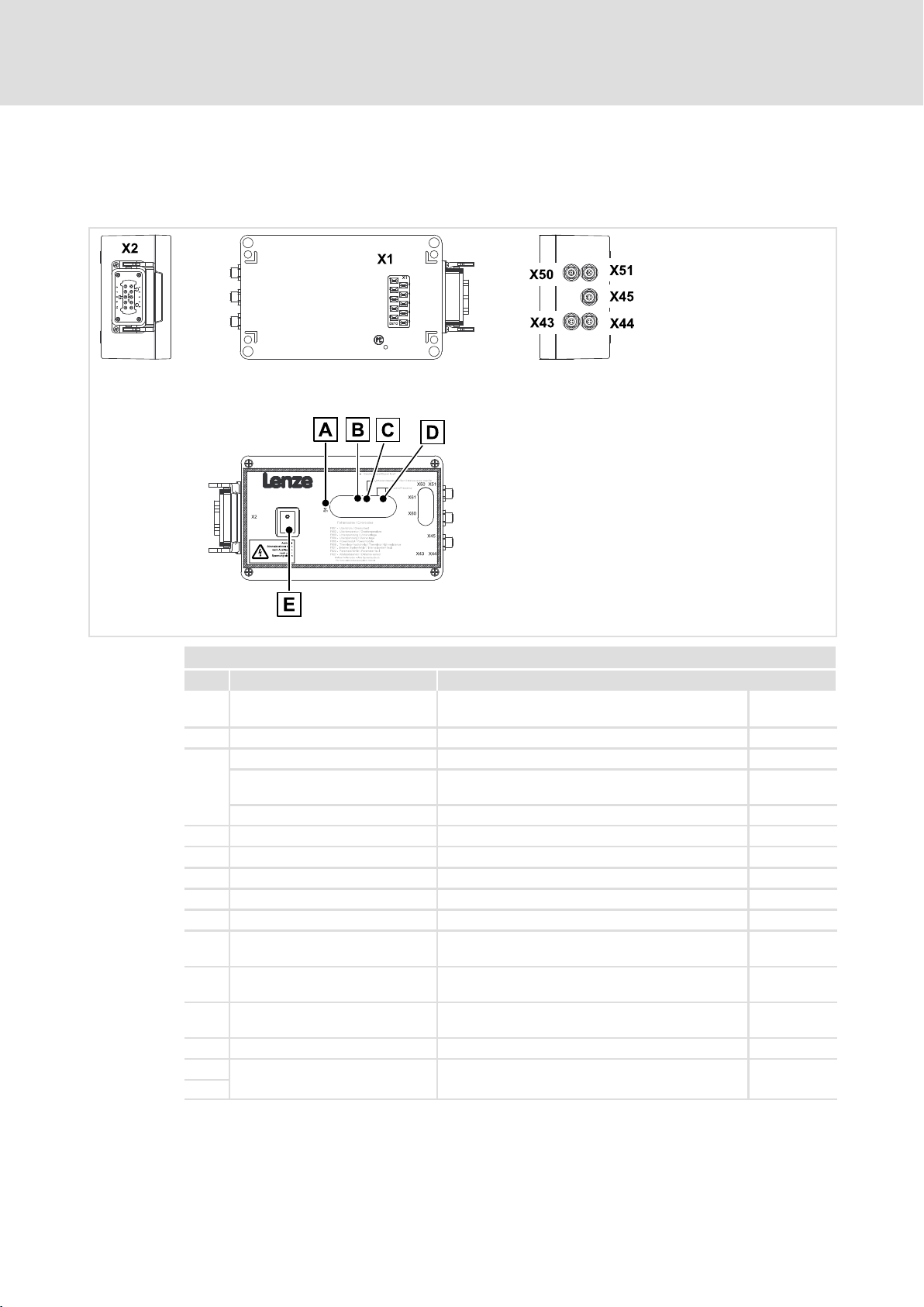
5.2 Dimensions
Mechanical installation
Dimensions
Power 0.75 kW
CCU210_002H
24
l
LDEDS−CCU210B EN 4.0
Page 25
Power 1.5 kW
Mechanical installation
Dimensions
5
LDEDS−CCU210B EN 4.0
l
CCU210_002B
25
Page 26
5
Mechanical installation
Dimensions
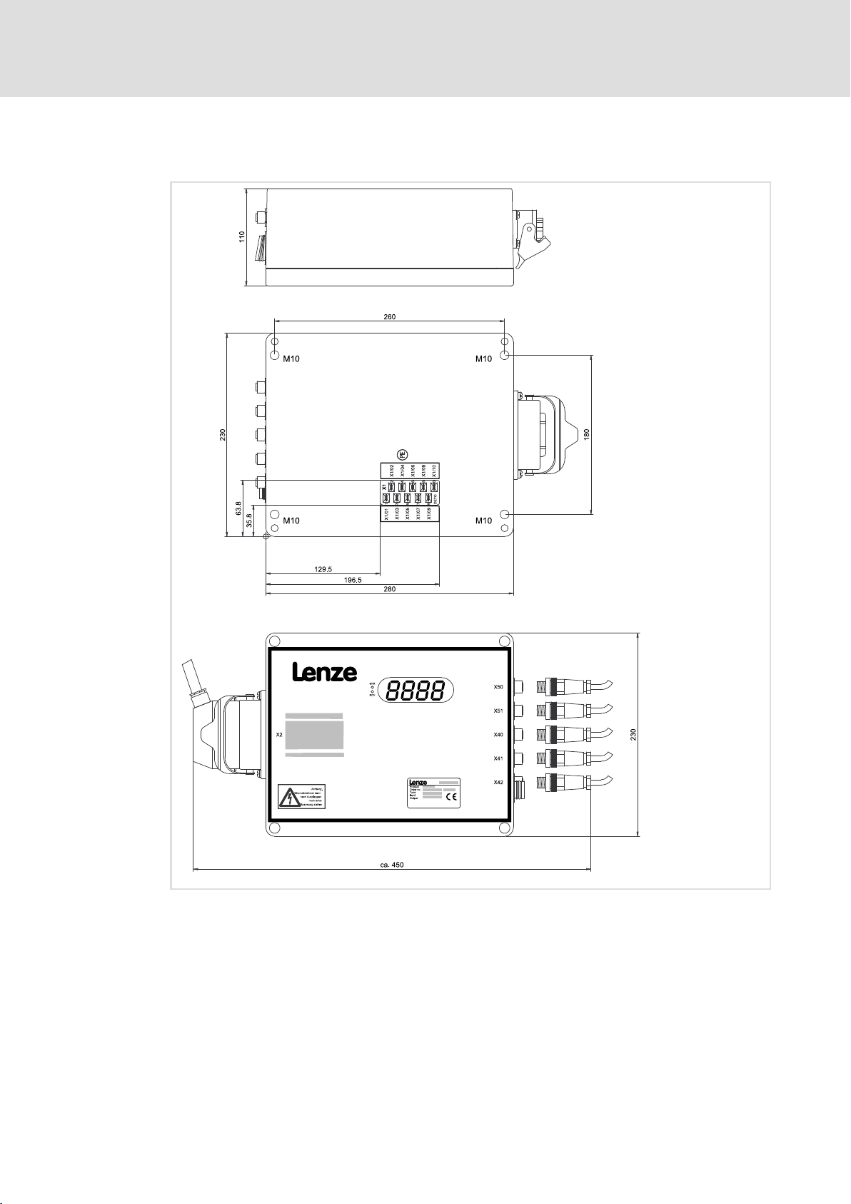
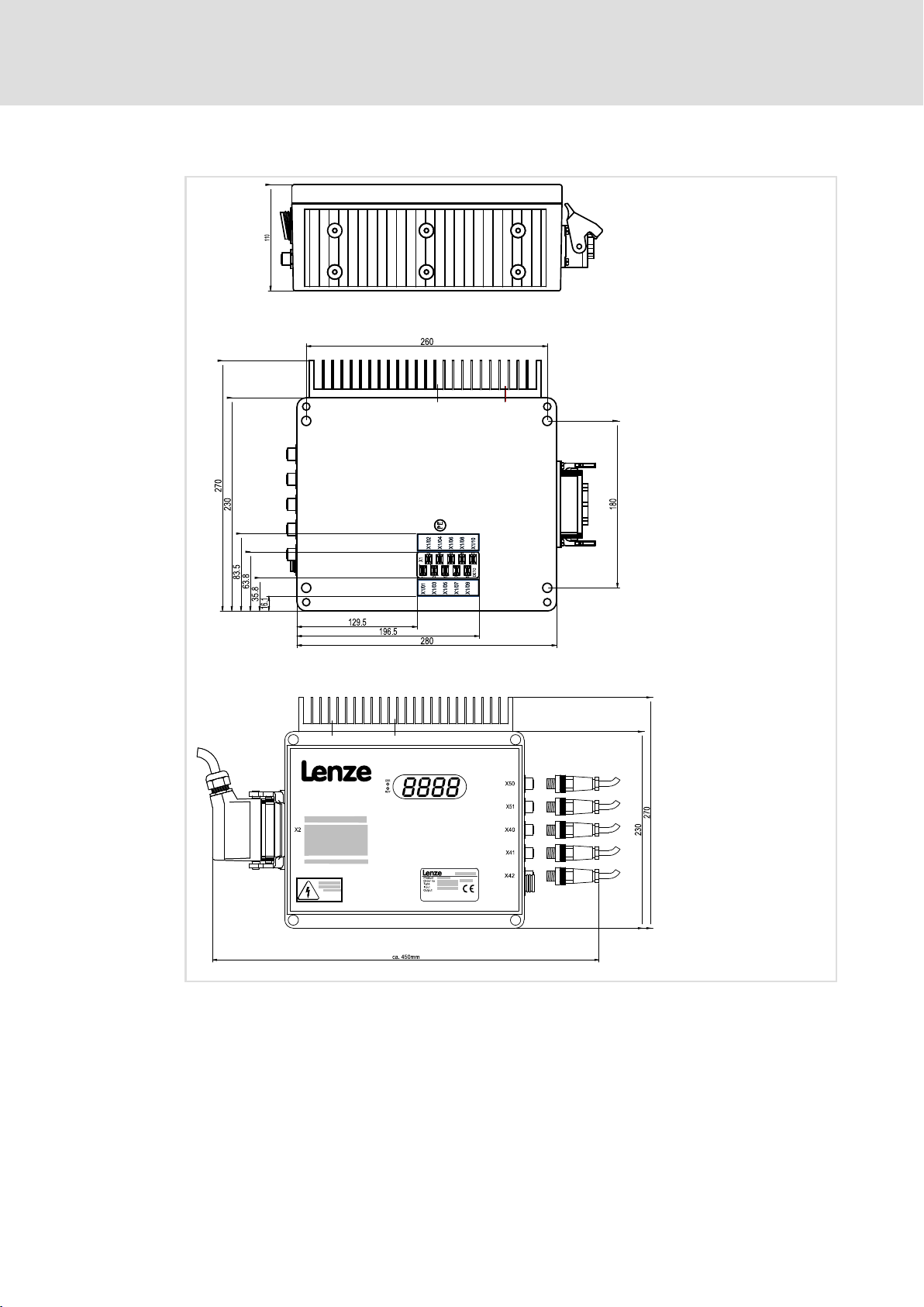
Power 2.2 kW
26
l
CCU210_002_2_2kW
LDEDS−CCU210B EN 4.0
Page 27

6 Electrical installation
6.1 Important notes
{ Danger!
ƒ The contacts for the X1 and X2 power connectors can carry dangerous
voltages when the control system is connected to the mains. Therefore
deenergise the control system before working on it.
ƒ After the connection of a PTC thermistor or a thermal switch (NC contact),
all control terminals are only base−insulated (single isolating distance):
– Protection against accidental contact in case the isolating distance is
defective only is ensured by external measures, e. g. double insulation.
ƒ The control system must be earthed via X1 to prevent injuries to persons
and breakdown.
Electrical installation
Important notes
6
) Note!
ƒ Supplied plastic covers on the connectors for the control connections and
interfaces:
– Be absolutely sure to keep the plastic covers!
– You must cover unused connections during transport, storage and
operation with the plastic covers to guarantee the IP 54 enclosure.
ƒ Labels in the area of the control connections:
– Do not remove labels!
– The IP 54 enclosure is only guaranteed with the label.
LDEDS−CCU210B EN 4.0
l
27
Page 28

6
Electrical installation
Important notes
EMC−compliant wiring
) Note!
In order to ensure the trouble−free operation of Lenze control systems on
monorail overhead conveyors, an EMC−compliant installation is requried. This
includes the following:
ƒ Conduct the motor cable as described in the technical data.
ƒ Install the motor connection cables (connections U, V, W) separately from
the sensor cables:
– Do not use a common cable duct.
– Do not lay the cables in parallel over longer distances.
– Minimum distance 10 cm.
– Keep the motor cable as short as possible.
ƒ Lay the supply cables for the sliding contacts of the bars separately to the
sensor cables:
– Do not use a common cable duct.
– Do not lay the cables over longer distances.
– Minimum distance 20 cm.
ƒ Connect control and data cable shields at both ends.
ƒ Prevent the formation of loops of the sensor cables when cables are too
long:
– Conveniently trim the sensor cables or directly lay them in the wire
harness by folding them up and interconnecting them using a cable tie, in
order to avoid interferences and magnetic inductions.
ƒ Earth the MOC vehicle directly via the earthing brushgear:
– Connect all movable parts to the cross beam or the main beam in a
low−resistance manner.
2
– Use copper braid strap or drain wire 4 mm
ƒ Series connections of the earthing are allowed:
– If a movable part is earthed, the proximate movable part can be earthed
on the previous movable part.
– For instance in the case of carriages, you can like this establish a closed
and low−resistance connection from the cross beam to the main beam
which the control is connected to, via several PE connections from the
motor bracket, control beam, front and rear carriage.
ƒ The responsibility for the compliance with the EMC Directive in the machine
application lies with the user.
.
28
l
LDEDS−CCU210B EN 4.0
Page 29
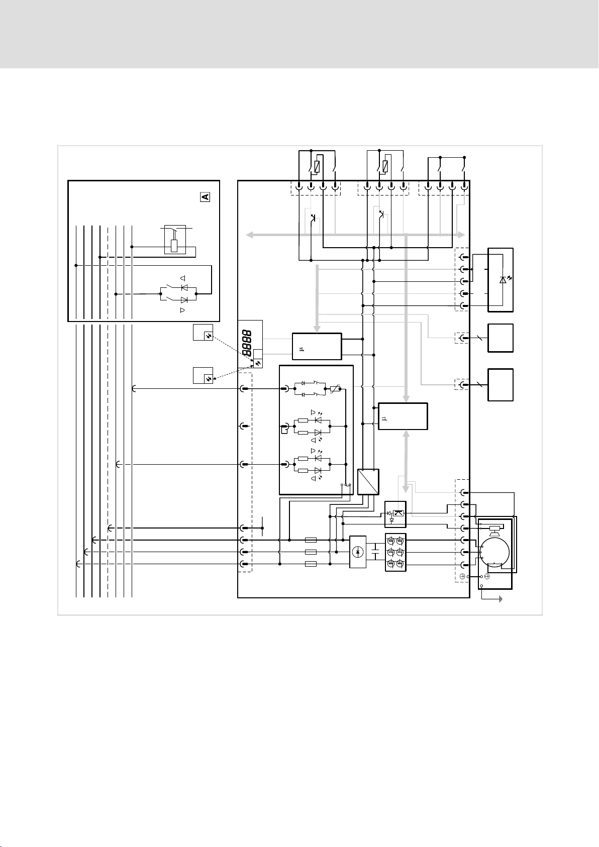
6.2 Basic circuit diagram
Power 0.75 kW
Electrical installation
Basic circuit diagram
6
DIN6
DIN5 / DOUT2
1
2
3
X45
L1/AC 400 V
PE
L2/AC 400 V
SS1/AC 400 V
L3/AC 400 V
SS2/AC 400 V
N
MS1/AC 230 V
4
1
X44
LDECBBF1xxxxxxH W
C
IrDA
PDA Ir-RC
(DISPLAY)
REL-1 REL-2
DIN4
DIN3 / DOUT1
2
3
4
DIN1
DIN2
1
2
3
X43
4
B
R S485
SensoPart
A
R S485
12345
8
EXM ID1
X50 X51
X61
8
PC
System -
X60
C
(FU)
busad apter
0 Control cabinet
1234 7 10
X1
+
GND
3
1
J1
2
PE
F1 F2 F3
24 V DC
~
5 9 10
-
+
W1
V1
M
3~
U1
1234
Th
-
+
PE
X2
CCU210_105
LDEDS−CCU210B EN 4.0
l
29
Page 30
6
Electrical installation
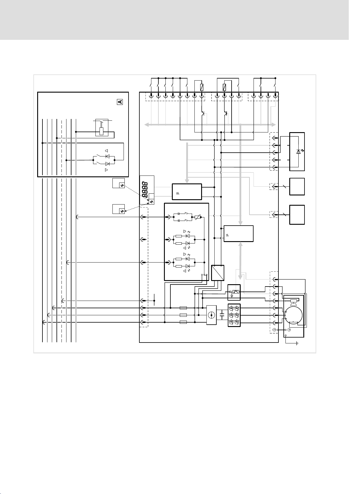
Basic circuit diagram
Power 1.5 kW and 2.2 kW
DIN8
DIN6
DIN5
DIN3
DIN4
1
2
X40
3
DIN7
DOUT2
4
5
6
7
8
1
X41
DIN2
DOUT1
2
3
4
1
X42
DIN1
2
3
4
L1/AC 400 V
PE
L2/AC 400 V
SS1/AC 400 V
L3/AC 400 V
SS2/AC 400 V
N
MS1/AC 230 V
B
R S485
SensoPart
A
R S485
12345
LDECBBF1xxxxxxH W
C
IrDA
PDA Ir-RC
(DISPLAY)
REL-1 REL-2
C
(FU )
+
GND
3
1
J1
2
24 VDC
~
8
EXM ID1
X50 X51
X61
8
PC
adapter
X60
System bus
0 Control cabinet
1234 7 10
X1
PE
5 9 10
1234
+ -
W1
V1
M
3~
U1
Th
-
+
F1 F2 F3
PE
X2
CCU210_105
30
l
LDEDS−CCU210B EN 4.0
Page 31

6.3 Mains connection
Electrical installation
Mains connection
6
CCU210_002C
X1 − Mains connection
Pin Connection Description Data
Connector: FASTON 6.3 x 0.8 mm flat
connector, 10−pole
1 L1 Phase L1
2 L2 Phase L2
3 L3 Phase L3
4 + PE PE conductor
5 n.c. Not assigned
6 n.c. Not assigned
7 SS1 Control bar 1
8 n.c. Not assigned
9 n.c. Not assigned
10 MS1 Message bar 1
The SS2 control bar is assigned according to customer’s specifications. (see project documentation)
3/PE/PEN AC 360 V − 0 % ... 528 V + 0 %
45 Hz − 0 % ... 65 Hz + 0 %
LDEDS−CCU210B EN 4.0
l
31
Page 32

6
Electrical installation
Motor connection
6.4 Motor connection
X2 − Motor connection
Pin Connection Description Data
1 U Phase U
2 V Phase V
3 W Phase W
4 + brake Brake supply voltage
5 +PTC Motor temperature monitoring PTC thermistor (PTC) or thermal contact (NC
6 n.c. Not assigned
7 n.c. Not assigned
8 n.c. Not assigned
9 − brake Brake supply voltage
10 −PTC Motor temperature monitoring PTC thermistor (PTC) or thermal contact (NC
+ PE PE conductor
CCU210_002D
Connector: Socket, Harting HAN−10B
contact)
contact)
32
l
LDEDS−CCU210B EN 4.0
Page 33

6.5 Control terminals
Device in a power range of 1.5 kW and 2.2 kW Devices in a power range of 0.75 kW
Common control terminals
X50 − external data memory
Pin Signal Description Data
Electrical installation
Control terminals
CCU210_002E CCU_210_002G
EXMID1 Connector: socket, 8−pole, M12
Connection of external data
memory
Max. 2 kB Depending on the application
6
X51 – anti−collsion sensor for RS485 SensoPart forward travel
Pin Signal Description Data
Connector: socket, 5−pole, M12, B−coded
1 +24V Supply
2 A RS485 signal A
3 GND Reference potential
4 B RS485 signal B
5 n. c. Not assigned
− Shld Shield Applied to the connector housing
X60, X61 – CAN system bus connection
Pin Signal Description Data
Two CAN system bus terminals for
parameter setting and
configuration
Connector: RJ45
Control terminals for devices in a power range of 1.5 kW and 2.2 kW
X40 − digital inputs DIN3 ... DIN7/digital output DOUT2
Pin Signal Description Data
Connector: socket, 8−pole, M12
1 DIN3 Digital input 3 HIGH +16 .... +26.5 V DC
2 DIN4 Digital input 4 LOW 0 ... +4 V
3 DIN5 Digital input 5 4 mA Current per input for 24 V DC
4
5 +24V DC Supply
6 DIN7 Digital input 7
7 GND Reference potential
8 DOUT2 Digital output 2
DIN6 Digital input 6
max.
200 mA
Permissible current loading per
output
If inductive loads are switched,
use a freewheeling diode as
close to the inductive load as
possible!
LDEDS−CCU210B EN 4.0
l
33
Page 34

6
Electrical installation
Control terminals
X41 − digital input DIN2 / digital output DOUT1
Pin Signal Description Data
Connector: socket, 4−pole, M12
1 +24V DC Supply HIGH +16 .... +26.5 V DC
2 DOUT1 Digital output 1 LOW 0 ... +4 V
3
4
X42 − digital inputs DIN1/DIN8
Pin Signal Description Data
1 +24V DC Supply HIGH +16 .... +26.5 V DC
2 DIN8 Digital input 8 LOW 0 ... +4 V
3 GND Reference potential
4 DIN1 Digital input 1
GND Reference potential 4 mA Current per input for 24 V DC
DIN2 Digital input 2 max.
200 mA
Connector: socket, 4−pole, M12
4 mA Current per input for 24 V DC
Permissible current loading per
output
If inductive loads are being
switched, freewheeling diodes
are required. Place the diodes
as close to the inductor load as
possible!
Control terminals for devices in a power range of 0.75 kW
X43 − digital inputs DIN1/DIN2
Pin Signal Description Data
Connector: socket, 4−pole, M12
1 +24V DC Supply HIGH +16 .... +26.5 V DC
2 DIN1 Digital input 1 LOW 0 ... +4 V
3
4 DIN2 Digital input 2
X44 − digital inputs DIN3/DOUT1 − DIN4
Pin Signal Description Data
1 +24V DC Supply HIGH +16 .... +26.5 V DC
1)
2
3 GND Reference potential
4 DIN4 Digital input 4
1)
GND Reference potential 4 mA Current per input for 24 V DC
Connector: socket, 4−pole, M12
DIN3 Digital input 3 LOW 0 ... +4 V
DOUT1
DIN/DOUT cannot be used at the same time!
Digital output 1 4 mA Current per input for 24 V DC
max.
200 mA
Permissible current loading per
output
If inductive loads are being
switched, a spark suppressor
must be used at the output!
34
l
LDEDS−CCU210B EN 4.0
Page 35

Electrical installation
Control terminals
X45 − digital inputs DIN5/DOUT2 − DIN6
Pin Signal Description Data
Connector: socket, 4−pole, M12
1 +24V DC Supply HIGH +16 .... +26.5 V DC
1)
2
3
4 DIN6 Digital input 6
1)
DIN5 Digital input 5 LOW 0 ... +4 V
DOUT2
GND Reference potential
DIN/DOUT cannot be used at the same time!
Digital output 2 4 mA Current per input for 24 V DC
max.
200 mA
Permissible current loading per
output
If inductive loads are being
switched, a spark suppressor
must be used at the output!
6
LDEDS−CCU210B EN 4.0
l
35
Page 36

6
6.6 Connection of system bus (CAN)
Electrical installation
Connection of system bus (CAN)
The CAN interface enables communication between a PC and a CCU210B control system.
The CAN system bus has the following functions:
ƒ Exchange and change of parameter values
ƒ Display of status messages
Before using the CAN interface ...
... install the following software components on your PC:
ƒ the "Global Drive Control" program
I Tip!
The system requirements and the steps required for installing the program are
described in the Global Drive Control or Global Drive Control easy user
manuals.
ƒ the device description file (*.pdb) provided by Lenze. The PC uses this file to identify
the control system.
– To ensure that you will not have to repeatedly look for the device description file,
copy the "82S8219V_10.pdb" file into the PDB directory of the "Global Drive
Control" program, e.g. C:\Program Files\Lenze\GDC_4_100\PDB\049.
36
l
LDEDS−CCU210B EN 4.0
Page 37

Electrical installation
Connection of system bus (CAN)
Connection to the PC
After installing the "Global Drive Control" software program and the device description
file, you can connect the device to your PC.
1. Remove the black cover on the control end of the device.
Device in a power range of 1.5 kW and 2.2 kW Devices in a power range of 0.75 kW
6
CCU210_002A CCU210_002G
Fig. 6−1 Position of the RJ45 sockets for the CAN system bus
0 Cover
X60/X61 CAN system bus connections
2. Plug the cable into RJ45 socket X60 or X61.
X60
X61
Fig. 6−2 Connecting the device to the PC using a system bus adapter
3. Connect the Sub−D interface of the cable with the system bus adapter.
4. Connect the system bus adapter to the PC.
LDEDS−CCU210B EN 4.0
l
CAN_CCU210B
37
Page 38

7
Commissioning
Before switching on
7 Commissioning
7.1 Before switching on
Before initial switch−on, check ...
ƒ ... whether the drive is undamaged.
ƒ ... the entire wiring with regard to completeness, short circuit and earth fault.
ƒ ... whether the mains and the motor are connected in correct phase relation.
ƒ ... whether the control bars and message bars are connected in correct phase
relation.
ƒ ... whether the configuration saved is valid for the application.
ƒ ... whether the parameters loaded are optimally adapted to the motor.
l 38
LDEDS−CCU210B EN 4.0
Page 39

7.2 Switch−on sequence
) Note!
ƒ Disconnect the control system from the mains before you attach or remove
the external EXMID1 data memory!
ƒ If the external EXMID1 data memory is attached or removed during voltage
is applied, the data saved on it can be damaged:
– If data are damaged, the control system reports the error F008.
– ^ 81
) Note!
ƒ Carefully follow the switch−on sequence described.
ƒ In case of faults during commissioning, the chapter "Troubleshooting and
fault elimination" (^ 78) will help you.
Commissioning
Switch−on sequence
7
How to switch on the control system:
1. If the control system is equipped with an external EXMID1 data memory:
– Connect the external EXMID1 data memory to plug X50.
2. Switch on the mains:
– After approx. 1 s the control system is ready for operation.
3. The control system behaves according to the specifications parameterised (signals
on the digital inputs):
A The control system is ready for operation if the display shows the status display 00
or the current operating status.
B The control system is not ready for operation if the signal in the display is blinking:
– A fault is active.
– Eliminate the fault. (¶ 78)
LDEDS−CCU210B EN 4.0
l
39
Page 40

8
Function library
Important notes
8 Function library
8.1 Important notes
Linking signals correctly
To operate the controller or to output status messages, you can freely link internal digital
and analog signals to sources and targets.
You can avoid faults if you observe the following:
ƒ Always select the source from the target:
– Ask yourself, where the signal comes from.
– Like this, you can easily find the correct entry for the corresponding code.
ƒ A source can have several targets:
– Thus, when a target is assigned to a source, undesirable or duplicate assignments
that are mutually exclusive may occur.
– Ensure that a source is only linked to the desired targets.
ƒ A target can only have one source.
Code table and signal flow diagram as a quick overview
In the code table all functions are numerically listed in the form of a "reference book" with
short explanations. (¶ 87 et seqq.)
The signal flow diagram shows in which way the most important codes are integrated in
the internal signal processing. (¶ 85)
40
l
LDEDS−CCU210B EN 4.0
Page 41

Function library
Operating mode
8.2 Operating mode
The vehicle control system is operated in the "V/f characteristic control" operating mode.
Codes for parameter setting
Code Possible settings Description
No. ñò < Byte Lenze Selection
C0015 RW EXT 4 0 Operating mode ^ 41
0 V/f characteristic control
1 Reserved
2 Reserved
C0016 RW EXT 4 400 Mains voltage ^ 41
0 {V} 480
C0017 RW EXT 4 0 Mains frequency ^ 41
0 50 Hz
1 60 Hz
C0018 Switching frequency of the inverter
in ...
1 RW EXT 4 2 8 kHz ... Parameter set 1
2 2 8 kHz ... Parameter set 2
Possible values
0 2 kHz
1 4 kHz
2 8 kHz
C0024 V/f characteristic – U-boost voltage
in ...
1 RW EXT 4 5.0 1 {%} 25.5 ... Parameter set 1
2 5.0 ... Parameter set 2
C0029 V/f characteristic – base frequency
in ...
1 RW EXT 4 50.0 0 {Hz} 120.0 ... Parameter set 1
2 50.0 ... Parameter set 2
^ 41
^ 41
^ 41
8
LDEDS−CCU210B EN 4.0
l 41
Page 42

8
8.3 Digital input signals
8.3.1 Description
Function library
Digital input signals
Description
The vehicle control system is equipped with digital inputs and a control bar evaluation to
evaluate digital input signals.
ƒ Basic circuit diagram: (¶ 29)
ƒ You can assign different switch−on and switch−off delays (C0406/C0407) to each
input signal.
ƒ The input signals can be logically linked (C0409) and assigned to internal control
functions via the assignment logic (C0410).
Digital inputs
There are 8 digital inputs to evaluate the sensors at the suspension gear of the monorail
overhead conveyor.
Additionally you can logically invert each input.
Control bar
Digital input signals via the control bar serve as a command specification by the
higher−level system control to the vehicle control system.
In the standard scope of supply the evaluation for a control bar is provided (SS1). On
customer request, the evaluation for a second control bar (SS2) can be activated.
For each control bar you can use the digital signals "positive half wave", "negative half
wave" and "full−wave" for function links.
) Note!
The reference phase in the Lenze setting is L3.
On customer request, the reference phase L1 can be supplied by adapting the
hardware.
42
l
LDEDS−CCU210B EN 4.0
Page 43

Function library
Digital input signals
Description
Codes for parameter setting
Code Possible settings Description
No. ñò < Byte Lenze Selection
C0406 Switch−on delay of digital input
RW EXT 4
1
2 0 ... DIN2
3 0 ... DIN3
4 0 ... DIN4
5 0 ... DIN5
6 0 ... DIN6
7 0 ... DIN7
8 0 ... DIN8
9 0 ... SS1 positive half wave
10 0 ... SS1 negative half wave
11 0 ... SS1 full−wave
12 0 Reserved
13 0 ... SS2 positive half wave
14 0 ... SS2 negative half wave
15 0 ... SS2 full−wave
16 0 Reserved
C0407 Switch−off delay of digital input
RW EXT 4
1
2 0 ... DIN2
3 0 ... DIN3
4 0 ... DIN4
5 0 ... DIN5
6 0 ... DIN6
7 0 ... DIN7
8 0 ... DIN8
9 0 ... SS1 positive half wave
10 0 ... SS1 negative half wave
11 0 ... SS1 full−wave
12 0 Reserved
13 0 ... SS2 positive half wave
14 0 ... SS2 negative half wave
15 0 ... SS2 full−wave
16 0 Reserved
0 {ms} 10000
0
0 {ms} 10000
0
signals
LOW ð HIGH ...
... DIN1
signals
HIGH ð LOW ...
... DIN1
8
^ 42
^ 42
LDEDS−CCU210B EN 4.0
l
43
Page 44

8
Function library
Digital input signals
Connection logic
C0408
RW EXT 1 0 1 255
8.3.2 Connection logic
SelectionLenzeByte<ñòNo.
Possible values
0 No inversion
1 DIN1
2 DIN2
4 DIN3
8 DIN4
16 DIN5
32 DIN6
64 DIN7
128 DIN8
DescriptionPossible settingsCode
Level inversion for digital inputs
à inputs are LOW−active
Add values of the inverted inputs:
e. g. DIN1, DIN3 and DIN5 are
LOW−active à C0408 = 21.
^ 42
By means of the connection logic (C0409) you can logically link digital inputs and control
bar inputs to each other:
ƒ The linkages 1−8 (C0409/1 ... C0409/8) are permanently set as "OR" operations.
ƒ The linkages 8−16 (C0409/8 ... C0409/16) are permanently set as "AND" operations.
ƒ For further function assignments the linkage results are provided as digital signal
sources.
44
l
LDEDS−CCU210B EN 4.0
Page 45

Function library
Digital input signals
Connection logic
Codes for parameter setting
Code Possible settings Description
No. ñò < Byte Lenze Selection
C0409 Logic operations of digital input
RW EXT 2
1
2 0 Link OR2
3 0 Link OR3
4 0 Link OR4
5 0 Link OR5
6 0 Link OR6
7 0 Link OR7
8 0 Link OR8
9 0 Link AND1
10 0 Link AND2
11 0 Link AND3
12 0 Link AND4
13 0 Link AND5
14 0 Link AND6
15 0 Link AND7
16 0 Link AND8
0 65535
0
Possible values
0 No linkage
1 DIN1
2 DIN2
4 DIN3
8 DIN4
16 DIN5
32 DIN6
64 DIN7
128 DIN8
256 SS1 positive half wave
512 SS1 negative half wave
1024 SS1 full−wave
2048 Reserved
4096 SS2 positive half wave
8192 SS2 negative half wave
16384 SS2 full−wave
31768 Reserved
signals
Link ORx = OR operation
Link ANDx = AND operation
Link OR1
Add values of the digital input
signals to define a linkage:
e. g. DIN1, SS1 full−wave and SS2
full−wave are to be assigned to link
OR2 (OR operation)
à C0409/2 = 17409.
8
^ 44
LDEDS−CCU210B EN 4.0
l
45
Page 46

8
Function library
Digital input signals
Assignment logic
8.3.3 Assignment logic
In the assignment logic (C0410) you assign digital signal sources, like for instance digital
inputs or linkage results, to the internal control functions. By this, you define the desired
control functions and responses to specific events.
Codes for parameter setting
Code Possible settings Description
No. ñò < Byte Lenze Selection
C0410 Linking digital input signals to an
RW EXT 4
1
2 0 Not assigned ... Motor V2 (incl. brake)
3 0 Not assigned ... Motor V3 (incl. brake)
4 0 Not assigned ... Motor V4 (incl. brake)
5 0 Not assigned ... Motor V5 (incl. brake)
6 0 Not assigned ... Motor V6 (incl. brake)
7 0 Not assigned ... Motor V7 (incl. brake)
8 0 Not assigned ... Motor V8 (incl. brake)
9 0 Not assigned ... CW/CCW rotation of motor
10 0 Not assigned Reserved
11 0 Not assigned ... Set fault
12 0 Not assigned ...Acknowledge fault
13 0 Not assigned ... Frequency inverter: change over
14 0 Not assigned ... DC−injection braking
15 0 Not assigned ... Open brake
16 0 Not assigned ... Stop1
17 0 Not assigned ... Stop2
18 0 Not assigned ... Stop3
19 0 Not assigned ... Stop4
20 0 Not assigned ... Frequency limitation 1
21 0 Not assigned ... Frequency limitation 2
22 0 Not assigned ... Frequency limitation 3
23 0 Not assigned ... Frequency limitation 4
24 0 Not assigned ... SensoPart: change over
25 0 Not assigned ... Deactivate control
0 Not assigned ... Motor V1 (incl. brake)
internal device function ...
l CW rotation = LOW
l CCW rotation = HIGH
parameter set
l Parameter set 1 = LOW
l Parameter set 2 = HIGH
parameter set
l Parameter set 1 = LOW
l Parameter set 2 = HIGH
^ 46
46
l
LDEDS−CCU210B EN 4.0
Page 47

Function library
Digital input signals
Assignment logic
DescriptionPossible settingsCode
SelectionLenzeByte<ñòNo.
C0410 (Continuation)
Linking digital input signals to an
internal device function ...
Possible values
0 Not assigned
1 DIN1 Digital input DIN1
2 DIN2 Digital input DIN2
3 DIN3 Digital input DIN3
4 DIN4 Digital input DIN4
5 DIN5 Digital input DIN5
6 DIN6 Digital input DIN6
7 DIN7 Digital input DIN7
8 DIN8 Digital input DIN8
9 SS1 positive half wave Control bar 1 positive half wave
10 SS1 negative half wave Control bar 1 negative half wave
11 SS1 full−wave Control bar 1 full−wave
12 Reserved
13 SS2 positive half wave Control bar 2 positive half wave
14 SS2 negative half wave Control bar 2 negative half wave
15 SS2 full−wave Control bar 2 full−wave
16 Reserved
... ...
31 Reserved
32 Link OR1 Result of OR operation 1
33 Link OR2 Result of OR operation 2
34 Link OR3 Result of OR operation 3
35 Link OR4 Result of OR operation 4
36 Link OR5 Result of OR operation 5
37 Link OR6 Result of OR operation 6
38 Link OR7 Result of OR operation 7
39 Link OR8 Result of OR operation 8
40 Link AND1 Result of AND operation 1
41 Link AND2 Result of AND operation 2
42 Link AND3 Result of AND operation 3
43 Link AND4 Result of AND operation 4
44 Link AND5 Result of AND operation 5
45 Link AND6 Result of AND operation 6
46 Link AND7 Result of AND operation 7
47 Link AND8 Result of AND operation 8
48 Reserved
... ...
63 Reserved
8
^ 46
LDEDS−CCU210B EN 4.0
l
47
Page 48

8
Function library
Digital input signals
Assignment logic
DescriptionPossible settingsCode
SelectionLenzeByte<ñòNo.
C0410 (Continuation)
Linking digital input signals to an
internal device function
64 HWC match code 1 HWC match code 1
65 HWC match code 2 HWC match code 2
66 HWC match code 3 HWC match code 3
67 HWC match code 4 HWC match code 4
68 HWC match code 5 HWC match code 5
69 HWC match code 6 HWC match code 6
70 HWC match code 7 HWC match code 7
71 HWC match code 8 HWC match code 8
72 HWC match code 9 HWC match code 9
73 HWC match code 10 HWC match code 10
74 HWC match code 11 HWC match code 11
75 HWC match code 12 HWC match code 12
76 HWC match code 13 HWC match code 13
77 HWC match code 14 HWC match code 14
78 HWC match code 15 HWC match code 15
79 HWC match code 16 HWC match code 16
80 Reserved
... ...
95 Reserved
96 HWC−OR1 Result of HWC OR operation
97 HWC−OR2 Result of HWC OR operation
98 HWC−OR3 Result of HWC OR operation
99 HWC−OR4 Result of HWC OR operation
100 HWC−OR5 Result of HWC OR operation
101 HWC−OR6 Result of HWC OR operation
102 HWC−OR7 Result of HWC OR operation
103 HWC−OR8 Result of HWC OR operation
104 Reserved
... ...
252 Reserved
253 Fixed LOW Signal level always is LOW
254 Fixed HIGH Signal level always is HIGH
255 Not assigned
^ 46
48
l
LDEDS−CCU210B EN 4.0
Page 49

8.4 Digital output signals
8.4.1 Description
The vehicle control system is equipped with digital outputs and a message bar output to
provide digital output signals.
ƒ Basic circuit diagram: (¶ 29)
ƒ The internal status signals are assigned to the output signals via the assignment
logic (C0415).
Digital outputs
There are 2 digital outputs to control the actor technology at the suspension gear of the
monorail overhead conveyor.
Additionally you can logically invert each output.
Message bar
Function library
Digital output signals
Description
8
The digital output signals via the message bar serve as a feedback from the vehicle control
system to the higher−level system control.
A message bar output (MS1) is provided.
You can output the digital signals "positive half wave" and "negative half wave".
) Note!
The reference phase in the Lenze setting is L3.
On customer request, the reference phase L1 can be supplied by adapting the
hardware.
Codes for parameter setting
Code Possible settings Description
No. ñò < Byte Lenze Selection
C0416
RW EXT 1 0 1 255
Possible values
0 No inversion
1 DOUT1
2 DOUT2
4 Reserved
8 Reserved
16 Message bar1 positive half wave
32 Message bar1 negative half wave
64 Reserved
128 Reserved
Level inversion for digital outputs
à outputs are LOW−active
Add values of the inverted outputs:
e. g. DOUT1 and message bar1
negative half wave are LOW−active
à C0416 = 33.
^ 49
LDEDS−CCU210B EN 4.0
l
49
Page 50

8
Function library
Digital output signals
Assignment logic
8.4.2 Assignment logic
In the assignment logic (C0415) you assign internal status signals to the message bar and
the digital outputs.
Codes for parameter setting
Code Possible settings Description
No. ñò < Byte Lenze Selection
C0415 Linking internal status signals to
RW EXT 4
1
2 0 Not assigned ...Digital output DOUT2
3 0 Not assigned Reserved
4 0 Not assigned Reserved
5 0 Not assigned ... Message bar1 positive half wave
6 0 Not assigned ... Message bar1 negative half wave
0 Not assigned ...Digital output DOUT1
Possible values
0 Not assigned
1 Motor V1 active
2 Motor V2 active
3 Motor V3 active
4 Motor V4 active
5 Motor V5 active
6 Motor V6 active
7 Motor V7 active
8 Motor V8 active
9 Motor CCW rotation active
10 Reserved
11 Fault active
12 Reserved
13 Frequency inverter: parameter set 2
active
14 Reserved
15 Brake is open
16 Stop 1 active
17 Stop 2 active
18 Stop 3 active
19 Stop 4 active
20 Frequency limitation 1 active
21 Frequency limitation 2 active
22 Frequency limitation 3 active
23 Frequency limitation 4 active
24 SensoPart: parameter set 2 active
25 Reserved
... ...
29 Reserved
30 HWC code range active
31 Reserved
digital output signal ...
^ 50
50
l
LDEDS−CCU210B EN 4.0
Page 51

Function library
Digital output signals
Assignment logic
DescriptionPossible settingsCode
SelectionLenzeByte<ñòNo.
C0415 (Continuation)
Linking internal status signals to
digital output signal ...
Possible values
32 Motor is running
33 Reserved
34 Status On/Off: OFF active
35 Status On/Off: OFF active or fault
active
36 Status On/Off: OFF active or fault
active or Stop 1 active or manual Ir
operation active
37 Reserved
38 Stop 1, 2, 3, 4 active or SensoPart
active
39 Frequency limitation 1, 2, 3, 4 active
or SensoPart active
40 Reserved
41 Reserved
42 SensoPart: Stop active
43 SensoPart: frequency limitation
active
44 Reserved
... ...
50 Reserved
51 Start−up warning or fault active
52 Reserved
... ...
59 Reserved
60 IrDA positioning active
61 IrDA position reached
62 Reserved
... ...
252 Reserved
253 Fixed LOW Signal level always is LOW
254 Fixed HIGH Signal level always is HIGH
255 Not assigned
8
^ 50
LDEDS−CCU210B EN 4.0
l
51
Page 52

8
Function library
Motor control
"Motor speed V1−V8" function
8.5 Motor control
8.5.1 "Motor speed V1−V8" function
By the "Motor speed V1−V8" functions (C0410/1 ... C0410/8), 8 speed values for each
parameter set are provided.
ƒ The functions are activated via digital signal sources (e. g. digital inputs).
– The brake opens automatically.
– The motor is activated with the frequency (C0011/1 ... C0011/8) that is
parameterised respectively.
– If two speeds are activated at the same time, the higher stage has priority.
Example: If V2 and V5 are activated at the same time, V5 is used.
ƒ If a "Stop function" is active, the "Motor speed V1−V8" function is inhibited. The
motor control is stopped. The motor is braked to V0 via the deceleration ramp of the
stop function (C0434/1 ... C0434/4).
ƒ If the "Frequency limitation" function is active, the "Motor speed V1−V8" function is
interrupted. The motor is controlled with the corresponding frequency
(C0440/1 ... C440/4).
The acceleration and deceleration times for V1−V8 can be set individually for each drive
frequency (C0012/1 ... C0012/8 and C0013/1 ... C0013/8). The direction of rotation is
controlled via C0410/9. A second parameter set can be activated via C0410/13.
Codes for parameter setting
Code Possible settings Description
No. ñò < Byte Lenze Selection
C0010 RW EXT 4 10000
0 {mm/min} 65535
C0011 Drive frequency for ...
RW EXT 4
1
2 0.0 ... V2
3 0.0 ... V3
4 0.0 ... V4
5 0.0 ... V5
6 0.0 ... V6
7 0.0 ... V7
8 0.0 ... V8
C0012 Acceleration time for ...
RW EXT 4
1
2 50 ... V2
3 50 ... V3
4 50 ... V4
5 50 ... V5
6 50 ... V6
7 50 ... V7
8 50 ... V8
0.0 {Hz} 120.0
0.0
1 {Hz/s} 255
50
Conversion factor: speed at 50 Hz
drive frequency
... V1
... V1
^ 52
^ 52
^ 52
52
l
LDEDS−CCU210B EN 4.0
Page 53

Function library
Motor control
"Motor speed V1−V8" function
DescriptionPossible settingsCode
SelectionLenzeByte<ñòNo.
C0013 Deceleration time for ...
RW EXT 4
1
2 50 ... V2
3 50 ... V3
4 50 ... V4
5 50 ... V5
6 50 ... V6
7 50 ... V7
8 50 ... V8
C0014 RW EXT 4 80
C0420 RW EXT 4 0
C0421 RW EXT 4 0
1 {Hz/s} 255
50
1 {Hz/s} 255
0 {ms} 20000
0 {ms} 20000
... V1
Deceleration time for quick stop
functions:
l On/Off switch
l Error
l SensoPart trip−out
Deceleration time:
start−up after mains connection
V0 ð Vx
Deceleration time:
start−up after On/Off switch to ON
V0 ð Vx
8
^ 52
^ 52
^ 52
^ 52
LDEDS−CCU210B EN 4.0
l
53
Page 54

8
Function library
Motor control
Stop functions
8.5.2 Stop functions
In order to interrupt the main functions "Motor V1−V8", you can use "Stop functions". For
this purpose, four independent functions are provided (C0410/16 ... C0410/19):
ƒ The functions are activated via digital signal sources (e. g. digital inputs).
ƒ For the deceleration of Vx to V0 separate deceleration ramps (C0434/1 ... C0434/4)
are provided.
ƒ For each function you can set deceleration times for the acceleration ramps
(C0432/1 ... C0432/4) and deceleration ramps (C0433/1 ... C0433/4).
ƒ You can set each function so that the stop function only is activated in the case of
one direction of rotation of the drive.
Codes for parameter setting
Code Possible settings Description
No. ñò < Byte Lenze Selection
C0430 Configuration of function ...
RW EXT 4
1
2 3 ... Stop 2
3 3 ... Stop 3
4 3 ... Stop 4
C0432 delay time:
RW EXT 4
1
2 0 ... Stop 2
3 0 ... Stop 3
4 0 ... Stop 4
C0433 delay time:
RW EXT 4
1
2 0 ... Stop 2
3 0 ... Stop 3
4 0 ... Stop 4
C0434 Deceleration ramp Vx ð V0 for ...
RW EXT 4
1
2 50 ... Stop 2
3 50 ... Stop 3
4 50 ... Stop 4
3 ... Stop 1
Possible values
1 Stop x only active in the case of CW
2 Stop x only active in the case of CCW
3 Stop x active in the case of CW and
0 {ms} 20000
0
0 {ms} 20000
0
1 {Hz/s} 255
50
rotation
rotation
CCW rotation
start−up V0 ð Vx after ...
... Stop 1
start of deceleration ramp Vx ð V0
after command ...
... Stop 1
... Stop 1
^ 54
^ 54
^ 54
^ 54
54
l
LDEDS−CCU210B EN 4.0
Page 55

Function library
Motor control
"Frequency limitation" function (speed limit)
8
8.5.3 "Frequency limitation" function (speed limit)
In order to interrupt the main functions "Motor V1−V8", the "Frequency limitation"
function can be used. If the function is active, it limits the drive frequency to the maximum
value that is respectively set (C0441/1 ... C0441/4). For this purpose, four independent
functions are provided (C0410/20 ... C0410/23):
ƒ The functions are activated via digital signal sources (e. g. digital inputs).
ƒ For the deceleration of Vx to the limited speed VLx there are separate deceleration
ramps (C0444/1 ... C0444/4).
ƒ For each function you can set deceleration times for the acceleration ramps
(C0442/1 ... C0442/4) and deceleration ramps (C0443/1 ... C0443/4).
ƒ You can set each function so that the frequency limitation only is activated in the
case of one direction of rotation of the drive.
Codes for parameter setting
Code Possible settings Description
No. ñò < Byte Lenze Selection
C0440 Configuration of function ...
RW EXT 4
1
2 3 ... Frequency limitation 2
3 3 ... Frequency limitation 3
4 3 ... Frequency limitation 4
C0441 Drive frequency for ...
RW EXT 4
1
2 0 ... Frequency limitation 2 (VL2)
3 0 ... Frequency limitation 3 (VL3)
4 0 ... Frequency limitation 4 (VL4)
C0442 delay time:
RW EXT 4
1
2 0 ... Frequency limitation 2
3 0 ... Frequency limitation 3
4 0 ... Frequency limitation 4
C0443 delay time:
RW EXT 4
1
2 0 ... Frequency limitation 2
3 0 ... Frequency limitation 3
4 0 ... Frequency limitation 4
3 ... Frequency limitation 1
Possible values
1 Frequency limitation only active in
2 Frequency limitation only active in
3 Frequency limitation active in the
0 {Hz} 120.0
0
0 {ms} 20000
0
0 {ms} 20000
0
the case of CW rotation
the case of CCW rotation
case of CW and CCW rotation
... Frequency limitation 1 (VL1)
acceleration VLx ðVx after
deactivation of ...
... Frequency limitation 1
start of deceleration ramp Vx ð VLx
after command ...
... Frequency limitation 1
^ 55
^ 55
^ 55
^ 55
LDEDS−CCU210B EN 4.0
l
55
Page 56

8
Function library
Motor control
"Open brake" function
DescriptionPossible settingsCode
SelectionLenzeByte<ñòNo.
C0444 Deceleration ramp Vx ð VLx for ...
RW EXT 4
1
2 50 ... Frequency limitation 2
3 50 ... Frequency limitation 3
4 50 ... Frequency limitation 4
1 {Hz/s} 255
50
... Frequency limitation 1
8.5.4 "Open brake" function
You can also open the motor brake via digital signal sources (C0410/15) without using the
"Motor V1−V8" functions.
In order to prevent an overload of the brake by triggering it for too long, a maximum
triggering time can be parameterised via C0451. After this time has elapsed, the brake
automatically engages even if a trigger signal is available.
If the "Motor V1−V8" functions are active, the motor brake always is open automatically.
^ 55
Codes for parameter setting
Code Possible settings Description
No. ñò < Byte Lenze Selection
C0450 RW EXT 4 0
0 Brake opens immediately Brake opens if C0410/15 = HIGH
1 Brake opens with delay Brake opens if C0410/15 = HIGH
C0451 RW EXT 4 0
0 {s} 1000 l C0451 = 0 s:
"Open brake" function:
configuration
and drive frequency = 0 Hz
"Open brake" function:
maximum activation time
– Brake opens if
C0410/15 = HIGH
– Brake closes if
C0410/15 = LOW
l C0451 > 0 s:
– Brake opens if
C0410/15 = HIGH
– Brake closes after the time set
if C0410/15 = HIGH
^ 56
^ 56
56
l
LDEDS−CCU210B EN 4.0
Page 57

8.6 Monitoring
8.6.1 Anti−collision sensor SensoPart
The SensoPart permanently measures the distance to a reflector on the vehicle ahead. The
distance is read out via a serial interface RS485 by the vehicle control system and is
evaluated according to the function parameterised.
Via a digital signal source (digital inputs, linkage result, etc…) you can switch over between
two SensoPart parameter sets (close−up range and long range, e. g. loaded or empty
vehicle).
For each parameter set, 2 distances, including hystereses in [mm], can be parameterised.
When an object is detected within the approach distance [mm] (speed limit), the speed is
limited to a freely parameterisable threshold [Hz].
The required braking distance towards the vehicle ahead, calculated via the speed [Hz] that
is currently travelled and the deceleration set [Hz/s], is added to the stopping distance
[mm]. Furthermore a parameterisable offset [mm] is added to this value. If the calculated
minimum braking distance to the vehicle ahead is reached, the control system starts to
brake on the parameterisable creeping speed [Hz]. When the parameterised stopping
distance [mm] is reached, a stop takes place. Only if the distance to the vehicle ahead is
increased via the minimum distance+hysteresis, a possibly parameterised start−up delay
time is awaited and the vehicle accelerates to the approach speed again. If the approach
distance+hysteresis are exceeded, the vehicle is accelerated to the travelling speed
specified.
Function library
Monitoring
Anti−collision sensor SensoPart
8
The "trip−out switching threshold" parameter (C0461) is used to stop the vehicle as quickly
as possible when the set value falls short if the alignment between reflector and SensoPart
(e.g. in curves) is poor.
) Note!
If no SensoPart is used, you have to deactivate the function in C0460!
LDEDS−CCU210B EN 4.0
l
57
Page 58

8
Function library
Monitoring
Anti−collision sensor SensoPart
Mode of operation
f [Hz]
C0476
C0466
0
C0468
0
V [mm/min]
C0462
x
B
C0468
C0464
C0478
x
B
x
B
x
B
x
B
C0472
Braking distance for braking to creeping speed, calculated for the respective
speed
V1
.
.
.
V8
x [mm]
VL
VS
CCU210_101
58
l
LDEDS−CCU210B EN 4.0
Page 59

Function library
Monitoring
Anti−collision sensor SensoPart
Step monitoring
For the SensoPart, a step monitoring function can be activated via parameter. The step
monitoring function is only active if the vehicle, while a travel command is pending, has
stopped and is at standstill due to the distance to the SensoPart sensor.
The step monitoring function is not active during travelling or if the vehicle is at standstill
due to a switched−off travel command.
If the control in the buffered state detects a step in the distance of the SensoPart sensor,
for a parameterisable time a warning signal is only shown on the display. After the time has
elapsed, this warning signal changes to a fault signal.
The warning signal and also the fault signal will delete automatically when the SensoPart
sensor detects a correct dístance value again (i. e. when it can "see" the mirror of the
vehicle in front again).
The fault signal must be acknowledged manually at the control if the SensoPart sensor can
no longer detect a distance to the vehicle in front (for instance, because the vehicle in front
has moved in the meantime).
8
After the step monitoring function has responded, the vehicle will start as usual if ...
ƒ the SensoPart sensor reports a correct distance which has exceeded the stop
distance parameterised (plus hysteresis) (i.e. "sees" a mirror).
ƒ the fault signal on the vehicle has been acknowledged manually and the SensoPart
sensor does not detect a mirror in front. PLEASE NOTE: This may also occur if the
fault signal is acknowledged while a person is standing in front of the vehicle.
The "Step monitoring function activated" status (i. e. distance has changed abruptly and
this state is still pending) is saved non−volatilely. If the SensoPart sensor still does not
detect a mirror after mains on/off, the warning signal and then the fault signal is output
again.
Codes for parameter setting
Code Possible settings Description
No. ñò < Byte Lenze Selection
C0128 RW EXT 4 1
0 Off
1 Error
2 Warning
C0261 RW EXT 2 1000
50 {inc/m} 5000
C0460 RW EXT 4 1
0 SensoPart inactive
1 SensoPart active − 57.6 kBaud
2 SensoPart active − 62.5 kBaud
3 SensoPart active − 38.4 kBaud
4 SensoPart active − 19.2 kBaud
5 SensoPart active − 9.6 kBaud
6 SensoPart active − 4.8 kBaud
Configuration of SensoPart error
monitoring
Encoder constant
SensoPart:
configuration
^ 57
^ 70
^ 57
LDEDS−CCU210B EN 4.0
l
59
Page 60

8
Function library
Monitoring
Anti−collision sensor SensoPart
DescriptionPossible settingsCode
SelectionLenzeByte<ñòNo.
C0461 RW EXT 4 500
0 {mm} 65535
C0462 SensoPart:
RW EXT 4
1
2 2000 ... Parameter set 2
C0463 SensoPart:
RW EXT 4
1
2 100 ... Parameter set 2
C0464 SensoPart:
RW EXT 4
1
2 50 ... Parameter set 2
C0466 SensoPart:
RW EXT 4
1
2 5.0 ... Parameter set 2
C0467 SensoPart:
RW EXT 4
1
2 1000 ... Parameter set 2
C0468 SensoPart:
RW EXT 4
1
2 50 ... Parameter set 2
C0469 RW EXT 1 0
C0470 RW EXT 1 10
0 {mm} 65535
2000
0 {mm} 65535
100
0 {mm} 65535
50
0 {Hz} 120.0
5.0
0 {ms} 20000
1000
1 {Hz/s} 255
50
0 Step monitoring inactive
1 Step monitoring active
2 {s} 20 Error delay
SensoPart:
distance for quick disconnection
stop distance in ...
... Parameter set 1
hysteresis for stop distance in ...
... Parameter set 1
traverse path with creeping speed
VS in ...
... Parameter set 1
drive frequency for creeping speed
VS in ...
... Parameter set 1
delay time:
start of the acceleration V0 ð VS in
...
... Parameter set 1
deceleration ramp for stop VS ð V0
in ...
... Parameter set 1
SensoPart step monitoring:
SensoPart step monitoring:
^ 57
^ 57
^ 57
^ 57
^ 57
^ 57
^ 57
^ 57
^ 57
C0472 SensoPart:
distance for switch−over to
approach speed ...
RW EXT 4
1
2 4000 ... Parameter set 2
C0473 SensoPart:
RW EXT 4
1
2 100 ... Parameter set 2
C0476 SensoPart:
RW EXT 4
1
2 20.0 ... Parameter set 2
60
0 {mm} 65535
4000
0 {mm} 65535
100
0 {Hz} 120.0
20.0
l
... Parameter set 1
hysteresis for short distance in ...
... Parameter set 1
drive frequency for approach speed
in ...
... Parameter set 1
^ 57
^ 57
^ 57
LDEDS−CCU210B EN 4.0
Page 61

Function library
DescriptionPossible settingsCode
SelectionLenzeByte<ñòNo.
C0478 SensoPart:
deceleration ramp Vx ð VLx for
frequency limitation distance in ...
RW EXT 4
1
2 50 ... Parameter set 2
C0610 R 4
8.6.2 I2t monitoring
1 {Hz/s} 255
50
0 {mm} 65535
... Parameter set 1
SensoPart: current distance
Monitoring
2
t monitoring
I
8
^ 57
^ 57
By means of the I
2
xt monitoring, the motor utilisation is monitored. The monitoring
simulates a motor protection switch.
How to configure the motor protection switch:
ƒ Enter the rated motor current in C0022.
ƒ Enter the tripping class in C0121.
ƒ Define the response in the case of overload in C0122.
( Stop!
Possible overheating of the motor
The I2xt monitoring does not present a full motor protection, as the motor
temperature calculated is reset every time the mains is switched off.
Possible consequences:
ƒ The connected motor can be overheated when the mains is switched on
again if ...
– ... the motor already is strongly heated and is continued to be overloaded.
– ... the cooling air supply is interrupted.
– ... the cooling air is too warm.
Protective measures:
ƒ Provide for a full motor protection that is additionally equipped with a PTC
thermistor or a thermal contact in the motor.
ƒ The PTC thermistor or thermal contact has to be wired and connected
correctly.
LDEDS−CCU210B EN 4.0
l
61
Page 62

8
Function library
Monitoring
2
t monitoring
I
I2t tripping characteristic
8
7.2
6
5
r
I/I
1.05
4
3
2
0.01 0.1 1 10 100 1000 100000.02
Class 10A
Class 10
t [s]
Class 10A
Class 10
(delivery status)
Tripping classes according to DIN EN 60947−4−2
Class 20
Class 30
I Output current
I
r
Rated motor current
Class 20
Class 30
start031
Example
(dashed line in the diagram)
If class 10 is set, the error message set is activated if output current I has the fourfold
amount of the rated motor current I
set for approx. 13 s.
r
Codes for parameter setting
Code Possible settings Description
No. ñò < Byte Lenze Selection
C0022 Rated motor current in ...
RW EXT 4
1
2 1.0 ... Parameter set 2
C0121 RW EXT 4 2
C0122 RW EXT 4 1
0 {A} 20.0
1.0
1 Tripping class CLASS 10A
2 Tripping class CLASS 10
3 Tripping class CLASS 20
4 Tripping class CLASS 30
0 Off
1 Error
2 Warning
... Parameter set 1
Tripping class for I2xt monitoring
Configuration of I2xt monitoring
^ 61
^ 61
^ 61
62
l
LDEDS−CCU210B EN 4.0
Page 63

Function library
Monitoring
Non−equivalence monitoring
8
8.6.3 Non−equivalence monitoring
By the non−equivalence monitoring you check two digital inputs each with regard to an
unequal input level. If the input level is the same for both digital inputs, an error is reported.
For non−equivalence monitoring, sensors with a normally open contact (no) and a normally
closed contact (nc) are suitable. Both contacts have to be switched at the same time.
There are four non−equivalence monitoring functions, which can be set via C0402. Each
monitoring function can exactly check two digital inputs with regard to each other.
In C0403 you set the error deceleration times.
Codes for parameter setting
Code Possible settings Description
No. ñò < Byte Lenze Selection
C0401 0 Configuration:
response of the non−equivalence
monitoring at the digital inputs
RW EXT 1
1
2 0 Non−equivalence monitoring 2
3 0 Non−equivalence monitoring 3
4 0 Non−equivalence monitoring 4
C0402 Configuration of non−equivalence
RW EXT 1
1
2 0 Non−equivalence monitoring 2
3 0 Non−equivalence monitoring 3
4 0 Non−equivalence monitoring 4
C0403 Deceleration of non−equivalence
RW EXT 4
1
2 0 Deceleration for C0402/2
3 0 Deceleration for C0402/3
4 0 Deceleration for C0402/4
0 255
0
Possible values
0 Error in the case of unequal levels at
1 Error in the case of equal levels at
0 255
0
Possible values
0 No monitoring
1 DIN1
2 DIN2
4 DIN3
8 DIN4
16 DIN5
32 DIN6
64 DIN7
128 DIN8
0 {ms} 10000
0
DINx
DINx
Non−equivalence monitoring 1
monitoring of the digital inputs
Non−equivalence monitoring 1
For the non−equivalence monitoring
only two digital inputs can be used
each.
Add values of the inputs monitored
and enter in C0402/x:
e. g. non−equivalence monitoring
for DIN3 and DIN5 = 20.
detection
Deceleration for C0402/1
^ 63
^ 63
^ 63
LDEDS−CCU210B EN 4.0
l
63
Page 64

8
Function library
Monitoring
Motor temperature monitoring
8.6.4 Motor temperature monitoring
The motor temperature either is monitored via a PTC inside the motor or via a thermal
contact. The response of the motor temperature monitoring (Error, Warning, Off) can be
defined via C0120.
Codes for parameter setting
Code Possible settings Description
No. ñò < Byte Lenze Selection
C0120 RW EXT 4 1
0 Off
1 Error
2 Warning
Configuration of motor
temperature monitoring
8.6.5 Output stage temperature monitoring
If the output stage temperature is > 100 °C for 3 seconds, an error message is output. You
can only acknowledge the message if the output stage temperature has been < 90 °C for
5 seconds. The current output stage temperature can be read in C0056.
^ 64
8.6.6 Parameter error
After power−on, all parameter data are read out from the flash memory and/or from the
external data connector. Then a checksum verification is carried out. A parameter error is
triggered if the checksum saved does not correspond to the checksum calculated or if a
new software version with a changed parameter repository has been loaded.
How to eliminate a parameter error:
1. Set all parameters to the Lenze setting (C0002 = 1).
2. Transfer the valid parameter set for the respective application again.
3. Wait until the PAr display goes out.
4. Switch off the supply voltage and then switch it on again.
) Note!
During the download of the parameters via PC or PDA, never switch off the
supply voltage as long as PAr is displayed in the 7−segment display!
Otherwise the transfer of the parameters is incomplete.
8.6.7 External error
64
The tripping of an external error is parameterised via the assignment logic (C0410). In
order to generate the fault message, a digital signal is used, e. g. a digital input.
l
LDEDS−CCU210B EN 4.0
Page 65

8.7 Infrared data transmission (IrDA)
Via the IrDA interface you parameterise the vehicle control system. Additionally you can
query status information and operate the vehicle control system in manual operation.
The IrDA eye is on the control system on the left next to the 7−segment display. Details on
the operation of the software surfaces can be found in the corresponding Manuals.
) Note!
How to ensure the correct data transmission:
ƒ The general IrDA guidelines from the "Physical Layer Specification Version
1.4" IrDA standard must be observed!
ƒ The files 82S8219V_XX.pdb and 82S8219V_XX.pfa must be saved on the
PDA in the \SD card\DFT−Projects\ directory.
ƒ The infrared windows of the PDA and the vehicle control system have to be
aligned with each other.
ƒ The distance should be as small as possible.
ƒ There must be no other nodes between the vehicle control system and PDA
within a 60° field of view!
ƒ Flash lamps, laser scanners or other light sources can interfere the IrDA
transmission!
Function library
Infrared data transmission (IrDA)
8
Codes for parameter setting
Code Possible settings Description
No. ñò < Byte Lenze Selection
C0126 RW EXT 4 0
0 Off
1 Error
2 Warning
Configuration of IrDA error
monitoring
^ 65
LDEDS−CCU210B EN 4.0
l
65
Page 66

8
Function library
IrDA positioning
8.8 IrDA positioning
By means of the IrDA positioning, an electric monorail overhead conveyor vehicle can be
positioned to a millimeter value specified via fieldbus within the IrDA transmission range
of the IRDS data station. This requires the connection of a CAN bus position measuring
sensor and a digital reference sensor to the IRDS data station. A bar code tape the position
values of which can be selected optionally due to homing, and which matches the
measuring system, is installed on the electric monorail overhead conveyor vehicle.
Safety block
SS
MS
CCU210B
IrDA IrDA
1) 2)
1)
Position
detection
DIN2
X40
CAN
X63
2)
Homing of the position
detection on a vehicle
or on goods to be conveyedt
24V
Fieldbus
X1
PLCIRDS
IRDS_004
Procedure:
ƒ A travel command via the SS control bar is continuously pending.
ƒ Via fieldbus, the system control (PLC) reports to the the IRDS infrared data station
(e.g. Profinet) via control bit that a vehicle is entering the area and that positioning
to the set position specified by the fieldbus is to be executed. From this time on,
there is an attempt to establish IrDA communication between the IRDS and the
vehicle control system.
ƒ The measuring system connected to the IRDS determines the actual position via the
position codes installed on the vehicle.
ƒ The position detection value is referenced to the value 0 mm by the "Homing"
sensor. The actual position of the vehicle is now also reported to the system control
as a status value via fieldbus. A new homing process by unintended switching of the
reference sensor is blocked and is only released again via the fieldbus control bit
after the next positioning activation.
66
ƒ An IrDA transmission error or position detection error is indicated to the system
control by the fieldbus.
ƒ Depending on the current travelling speed and the deceleration ramp set, the
vehicle control system calculates the brake application point required and executes
positioning to the position specified.
l
LDEDS−CCU210B EN 4.0
Page 67

Travelling
speed
Approach speed
(parameter)
Function library
8
IrDA positioning
v
Deceleration ramp
(parameter)
Position 0
(selection)
s
Braking distance
(calculated)
Approach path
(parameter)
ƒ Via IrDA, the vehicle control system reports to the infrared data station that
positioning has been carried out successfully (position reached and drive stopped),
and the data station indicates this to the system control as fieldbus status bit.
ƒ Exiting the position and thus the deactivation of the positioning function is
triggered by resetting the fieldbus control bit.
Codes for parameter setting
Code Possible settings Description
No. ñò < Byte Lenze Selection
C0131 RW EXT 4 0
0 Off
1 Error
2 Warning
C0491 RW EXT 2 150
0 {mm} 2000
C0492 RW EXT 4 5.0
1 {Hz} 50.0
C0493 RW EXT 1 50
1 {Hz/s} 255
C0495 RW EXT 2 3
1 {mm} 100
C0496 RW EXT 2 3
1 {mm} 100
C0612 R 2
0 {mm} 32768
Configuration of positioning error
monitoring
IrDA positioning approach path
IrDA positioning approach speed
IrDA positioning deceleration time
IrDA positioning braking distance
correction
IrDA positioning position window
Status of IrDA position value [mm]
IRDS_005
^ 66
^ 66
^ 66
^ 66
^ 66
^ 66
^ 66
LDEDS−CCU210B EN 4.0
l
67
Page 68

8
Function library
Infrared remote control (IrRC)
8.9 Infrared remote control (IrRC)
Via the infrared remote control you can operate the vehicle control system in manual
operation.
In C0480 you configure the change−over to the manual infrared operation via the key
[green].
You exit the manual infrared operation by pressing the key [red] or by pressing the On/Off
switch.
) Note!
The manual infrared operation is not reset by mains switching.
In the manual infrared operation the following functions are provided:
Key Function Comment
0 Acknowledge error An error can also be acknowledged in automatic operation
1 V1
2 V2
3 V3
4 V4
5 V5
6 V6
7 V1
8 V2
9 V3
F4 Open brake
by the key [0]:
For this, press the key [0] for approx. 1.5 seconds.
Activation of the motor with clockwise rotating field and Vx
Activation of the motor with anti−clockwise rotating field
and Vx
68
l
LDEDS−CCU210B EN 4.0
Page 69

Function library
Infrared remote control (IrRC)
Codes for parameter setting
Code Possible settings Description
No. ñò < Byte Lenze Selection
C0480 RW EXT 4 2
0 Ir−RC inactive
1 Activation by key [green] How to activate the manual
2 Activation by key [green] and
three−digit code
C0481 RW EXT 4 0
0 IR−RC display switch−over not active
1 IR−RC display switch−over with keys
[], [¯], and [F1] active
Activation method for infrared
remote control Ir−RC
infrared operation:
1. Press key [green] for
approx. 1 second.
2. Manual infrared operation is
active.
How to activate the manual
infrared operation:
1. Press key [green] for
approx. 1 second.
2. Automatic operation is
interrupted.
3. In the 7−segment display a
three−digit number is shown.
4. Enter this number correctly via
the IR−RC keys within the next 5
seconds.
5. Manual infrared operation is
active.
If the entry is incorrect, the vehicle
control system automatically
switches over to automatic
operation again.
Infrared remote control display
switch−over
8
^ 68
^ 68
LDEDS−CCU210B EN 4.0
l
69
Page 70

8
8.10 Half Wave Code (HWC)
Function library
Half Wave Code (HWC)
The Half Wave Code (HWC) is used to specify commands from the higher−level system
control to the vehicle control system. Like this, up to 200 different commands can be
transmitted on one control bar (SS2).
"HWC Match Codes" (HWC1−16) can be linked to control functions. When an HWC
command that is entered as "HWC Match Code" is received, the function linked to it is
executed. In addition, logic OR operations can be defined by "HWC Match Codes".
Example:
Request:
HWC command 4 ...forward travel with V1
HWC command 5 ...backward travel with V1
HWC command 6 ...forward travel with V2
HWC command 7 ...backward travel with V2
Parameter settings to solve the request:
HWC Match Code 1 (C0244/1) = 4
HWC Match Code 2 (C0244/2) = 5
HWC Match Code 3 (C0244/3) = 6
HWC Match Code 4 (C0244/4) = 7
HWC−OR1 (C0245/1) = 6 (HWC2 OR HWC4)
Function of motor V1 (C0410/1) = 64 (link to HWC1)
Function of motor V2 (C0410/2) = 65 (link to HWC2)
Function of motor V3 (C0410/3) = 66 (link to HWC3)
Function of motor V4 (C0410/4) = 67 (link to HWC4)
Function of CCW rotation (C0410/9) = 96 (link to HWC−OR1)
70
l
LDEDS−CCU210B EN 4.0
Page 71

Function library
Half Wave Code (HWC)
Speed selection
With the "HWC Code Range", an HWC command range can be used as speed selection. For
this purpose, a speed (e.g. minimum assembly line speed) is assigned to a command
number; a higher speed (e.g. maximum assembly line speed) is assigned to a higher
command number. The speeds for all command numbers in−between are automatically
calculated by the control system.
Calculation of the variable speed (Vv) when using the "HWC Code Range":
HWC_min ...C0251/1
HWC_max ...C0251/2
Vv_min ...C0252/1
Vv_max ...C0252/2
HWC_act ...currently received HWC command
Vv = Vv_min + (HWC_act −HWC_min) * ((Vv_max −Vv_min) / (HWC_max −HWC_min))
Example:
HWC_min = 10
HWC_max = 190
Vv_min = 500 mm/min
Vv_max = 5000 mm/min
HWC_act = 11
8
Vv = 500 mm/min + (11 −10) * ((5000 mm/min −500 mm/min) / (190 −10))
Vv = 500 mm/min + 1 * 25 mm/min = 525 mm/min
Codes for parameter setting
Code Possible settings Description
No. ñò < Byte Lenze Selection
C0240 RW EXT 1 2
1 HWC via control bar 1 SS1
2 HWC via control bar 2 SS2
C0241 RW EXT 1 3
1 15
C0242 RW EXT 1 3
2 15
C0243 RW EXT 1 0
0 Standard
1 FI automatic stop
2 Fast asynchronous 0 detection
3 FI automatic stopn and fast
asynchronous 0 detection
Configuration of HWC control bar
Number of HWC commands for
acceptance
Number of HWC command changes
for deletion
Special HWC operating mode
^ 70
^ 70
^ 70
^ 70
LDEDS−CCU210B EN 4.0
l
71
Page 72

8
Function library
Half Wave Code (HWC)
DescriptionPossible settingsCode
SelectionLenzeByte<ñòNo.
C0244 HWC match codes
RW EXT 1 0 0 201
1
2 HWC match code 2
3 HWC match code 3
4 HWC match code 4
5 HWC match code 5
6 HWC match code 6
7 HWC match code 7
8 HWC match code 8
9 HWC match code 9
10 HWC match code 10
11 HWC match code 11
12 HWC match code 12
13 HWC match code 13
14 HWC match code 14
15 HWC match code 15
16 HWC match code 16
C0245 Logic OR operations for HWC match
RW EXT 2 0 0 65535
1
2 HWC−OR2
3 HWC−OR3
4 HWC−OR4
5 HWC−OR5
6 HWC−OR6
7 HWC−OR7
8 HWC−OR8
C0250 RW EXT 1 0
0 No control
1 Control active
2 Control with pick−up after stop
C0251 HWC code range commands
RW EXT 1 201 1 201
1
2 HWC command for highest variable
C0252 HWC code range speeds
RW EXT 2 500 10 {mm/min} 65535
1
2 HWC highest variable speed
C0254 RW EXT 1 50
1 {Hz/s} 255
C0255 RW EXT 1 50
1 {Hz/s} 255
function
HWC match code 1
codes
HWC−OR1
HWC code range control mode
HWC command for lowest variable
speed (Vv_min)
speed (Vv_max)
HWC lowest variable speed
(Vv_min)
(Vv_max)
HWC acceleration time for variable
speed Vv
HWC deceleration time for variable
speed Vv
^ 70
^ 70
^ 70
^ 70
^ 70
^ 70
^ 70
72
l
LDEDS−CCU210B EN 4.0
Page 73

SelectionLenzeByte<ñòNo.
C0605 R 1
0 201
8.11 Open and closed loop control
A virtual set position is continuously calculated from the setpoint frequency specified,
which is usually determined via HWC code range. This set position is compared to the
actual position, which is determined by means of an actual value encoder (e.g. incremental
encoder), and is compensated correspondingly. It is attempted to reach the rated slip of the
motor by reducing the boost voltage and to compensate greater system deviations by
adapting the actual frequency.
For setting the control, only the encoder constant [Inc/m], the gearbox factor [mm/min],
and the control limitation [Hz/10] have to be parameterised.
Function library
Open and closed loop control
DescriptionPossible settingsCode
Status of current HWC command
8
^ 70
For monitoring, an error message can be generated when a parameterisable maximally
permissible system deviation is exceeded. Furthermore a corresponding error message for
the event that the control is active and the feedback (e.g. defective pulse encoder) is not
working is output.
Codes for parameter setting
Code Possible settings Description
No. ñò < Byte Lenze Selection
C0129 RW EXT 4 0
0 Off
1 Error
2 Warning
C0130 RW EXT 4 0
0 Off
1 Error
2 Warning
C0250 RW EXT 1 0
0 No control
1 Control active
2 Control with pick−up after stop
function
C0257 RW EXT 4 5.0
1.0 {Hz} 10.0
C0258 RW EXT 2 200
2 {mm} 5000
C0261 RW EXT 2 1000
50 {inc/m} 5000
Configuration of encoder error
monitoring
Configuration of error monitoring
system deviation
HWC code range control mode
HWC control limitation (± of
setpoint frequency)
HWC maximum system deviation
Encoder constant
^ 70
^ 70
^ 70
^ 70
^ 70
^ 70
LDEDS−CCU210B EN 4.0
l
73
Page 74

8
Function library
Open and closed loop control
C0264 RW EXT 4 1.5
C0265 RW EXT 4 5.0
C0606 R 2
C0607 R 2
SelectionLenzeByte<ñòNo.
1 {%} 25.5
4 {%} 25.5
0 {mm} 65535
0 {mm} 32768
DescriptionPossible settingsCode
Voltage control V−boost minimum
Voltage control V−boost maximum
Status of encoder position value
Status of system deviation
^ 70
^ 70
^ 70
^ 70
74
l
LDEDS−CCU210B EN 4.0
Page 75

Function library
Status messages
8.12 Status messages
By means of the status messages you are quickly provided with an overview of the vehicle
control system status.
Codes for parameter setting
Code Possible settings Description
No. ñò < Byte Lenze Selection
C0050 R 4
0 {Hz} 120.0
C0053 R 4
0 {V} 1000
C0054 R 4
0 {A} 20.0
C0056 R 4
0 {°C} 255
C0179 R INT 4
0 {min} 7884000
C0180 R 1
0 {s} 59
C0183 Limit values of the DC−bus voltage
R 4 0 {V} 1000
1
2 Maximum
C0184 Limit values of the current value
R INT 4 0 {A} 20.0
1
2 Maximum
C0186 Limit values of the output stage
R INT 4 0 {°C} 255
1
2 Maximum
C0196 R INT 4
0 {°C} 255
Current drive frequency
Current DC−bus voltage
Current motor current
Current output stage temperature
Power−on time
Seconds counter
Minimum
Reserved
temperature
Minimum
Average output stage temperature
8
^ 75
^ 75
^ 75
^ 75
^ 75
^ 75
^ 75
^ 75
^ 75
^ 75
LDEDS−CCU210B EN 4.0
l
75
Page 76

8
Function library
Status messages
DescriptionPossible settingsCode
SelectionLenzeByte<ñòNo.
C0601 R 2 Status of digital inputs (bit coded)
0 65535
Bit 0 Status DIN1 Digital input DIN1
Bit 1 Status DIN2 Digital input DIN2
Bit 2 Status DIN3 Digital input DIN3
Bit 3 Status DIN4 Digital input DIN4
Bit 4 Status DIN5 Digital input DIN5
Bit 5 Status DIN6 Digital input DIN6
Bit 6 Status DIN7 Digital input DIN7
Bit 7 Status DIN8 Digital input DIN8
Bit 8 Status SS1 positive half wave Control bar 1 positive half wave
Bit 9 Status SS1 negative half wave Control bar 1 negative half wave
Bit 10 Status SS1 full−wave Control bar 1 full−wave
Bit 11 Reserved
Bit 12 Status SS2 positive half wave Control bar 2 positive half wave
Bit 13 Status SS2 negative half wave Control bar 2 negative half wave
Bit 14 Status SS2 full−wave Control bar 2 full−wave
Bit 15 Reserved
C0602 R 2 Status of logic operations (bit
0 65535
Bit 0 Status link OR1
Bit 1 Status link OR2
Bit 2 Status link OR3
Bit 3 Status link OR4
Bit 4 Status link OR5
Bit 5 Status link OR6
Bit 6 Status link OR7
Bit 7 Status link OR8
Bit 8 Status link AND1
Bit 9 Status lnk AND2
Bit 10 Status link AND3
Bit 11 Status link AND4
Bit 12 Status link AND5
Bit 13 Status link AND6
Bit 14 Status link AND7
Bit 15 Status link AND8
C0603 R 1 Status of digital outputs (bit coded)
0 255
Bit 0 Status DOUT1 Digital output DOUT1
Bit 1 Status DOUT2 Digital output DOUT2
Bit 2 Reserved
Bit 3 Reserved
Bit 4 Status MS1 positive half wave Message bar 1 positive half wave
Bit 5 Status MS1 negative half wave Message bar 1 negative half wave
Bit 6 Reserved
Bit 7 Reserved
coded)
OR operations
AND operations
^ 75
^ 75
^ 75
76
l
LDEDS−CCU210B EN 4.0
Page 77

C0605 R 1
C0606 R 2
C0607 R 2
C0612 R 2
C0620 R EXT 4
SelectionLenzeByte<ñòNo.
0 201
0 {mm} 65535
0 {mm} 32768
0 {mm} 32768
0 4294967295
Function library
Status messages
DescriptionPossible settingsCode
Status of current HWC command
Status of encoder position value
Status of system deviation
Status of IrDA position value [mm]
Parameters: checksum (without
C0520, C0521, C0522 and C0523)
8
^ 70
^ 70
^ 70
^ 66
^ 75
LDEDS−CCU210B EN 4.0
l
77
Page 78

9
Troubleshooting and fault elimination
Status display
9 Troubleshooting and fault elimination
9.1 Status display
Pos. LED ColourStatus Description
CCU210_002F
0 LED display: drive status
1 4−digit 7−segment display for error
messages, warning signals, and
status messages
0 ERR red
RDY green
off No fault
flashing Fault active
on Device enabled
flashing Device inhibited
78
l
LDEDS−CCU210B EN 4.0
Page 79

Troubleshooting and fault elimination
Standard displays
Standard displays during operation (C0500 = 0)
Pos. Display Description
1
1
8.
8. 8. 8. Power−up display for 0.5 s
2. 3 4 Software version for 0.5 s
f 8 8 8 Error message (blinking)
h 8 8 8 Warning signal (blinking)
I n h Controller inhibit active (C0040)
o f f ON/OFF switch in OFFposition
P A R Parameters are saved in the EEPROM
P d A Manual PDA operation via IrDA active
I R C Manual infrared operation active
1 V1 forwards active
2 V2 forwards active
3 V3 forwards active
4 V4 forwards active
5 V5 forwards active
6 V6 forwards active
7 V7 forwards active
8 V8 forwards active
1 − V1 backwards active
2 − V2 backwards active
3 − V3 backwards active
4 − V4 backwards active
5 − V5 backwards active
6 − V6 backwards active
7 − V7 backwards active
8 − V8 backwards active
R 8. 8 8 Vv (variable frequency selection HWC Code Range) forward active
d Starting delay function active
P o. 8 8 IrDA positioning active
P o. −| |− IrDA positioning − position reached
1 ’ SensoPart: parameter set 1 active
2 ’ ’ SensoPart: parameter set 2 active
B o "Open brake" active
s 1. Stop 1 active
s 2. Stop 2 active
s 3. Stop 3 active
s 4. Stop 4 active
s d. SensoPart: stop distance active
s e. SensoPart: stop "Emergency distance" active
l b. SensoPart: creeping speed active
l d. SensoPart: approach speed active
l 1. Frequency limitation 1 active
l 2. Frequency limitation 2 active
l 3. Frequency limitation 3 active
l 4. Frequency limitation 4 active
8 8 Current drive frequency [Hz]
9
Status display
LDEDS−CCU210B EN 4.0
l
79
Page 80

9
Troubleshooting and fault elimination
Status display
Special displays
Via C0500 you can activate some special displays which are shown during operation instead of the
standard displays.
Pos. Display Description
1
− 88.8Drive frequency with sign [Hz]
8 8 8 U DC−bus voltage [V]
8 8. 8 A Motor current [A]
8 8 8 C Output stage temperature [°C]
8 8 8 8 Status of the digital inputs and control bars [hex]
8 8 Status of the digital outputs and message bars [hex]
8 8 8 8 SensoPart: distance [mm]
8 8 Status of the seconds counter [s]
C 8 8 8 HWC command status
8 8 8 8 Status of encoder position value [mm]
− 8 8 8 Status of system deviation with sign [mm]
− 8 8 8 Status of IrDA difference position with sign [mm]
8. 8. 8. 8. User−specific display
Codes for parameter setting
Code Possible settings Description
No. ñò < Byte Lenze Selection
C0500 RW EXT 4 0
0 Standard display
1 Drive frequency with sign [Hz]
2 DC−bus voltage [V]
3 Motor current [A]
5 Output stage temperature [°C]
7 Status of the digital inputs and
control bars [hex]
8 Status of the digital outputs and
message bars [hex]
9 SensoPart: distance [mm]
10 Status of the seconds counter [s]
11 HWC command status
12 Status of encoder position [mm]
13 Status of system deviation [mm]
15 IrDA position value [mm]
201 Reserved for customer−specific
displays
Display code for 7−segment display
^ 80
80
l
LDEDS−CCU210B EN 4.0
Page 81

Troubleshooting and fault elimination
Fault messages
9.2 Fault messages
In the fault memory all error messages occurred so far are recorded. The error number is
written in C0168 and the corresponding error occurrence time in C0169. For the error
occurrence time the mains operating time in minutes from C0179 is used.
The fault memory works like a shift register:
ƒ The latest error is always saved in C0168/1.
ƒ The first error is always saved in C0168/10.
Codes for parameter setting
Code Possible settings Description
No. ñò < Byte Lenze Selection
C0160 R 4
0 255
C0161 R 4
0 255
C0167
[PWD]
C0168 Fault memory: no. of the 10 faults
RW 4 0
0 Action executed
1 Delete fault memory and/or limit
R INT 4 1 255
1
2 Error 2
3 Error 3
4 Error 4
5 Error 5
6 Error 6
7 Error 7
8 Error 8
9 Error 9
10 Error 10 (first)
value memory
No. of the current warning signal
No. of the current error message
Fault memory (C0168, C0169) and
limit value memory (C0183−C0196)
are deleted if:
l the service password has been
entered in C0007 and
l C0167 is set to "1".
Only the limit value memory
(C0183−C0196) is deleted if:
l the user password has been
entered in C0007 and
l C0167 is set to "1".
that occurred last
Error 1 (latest)
9
^
81
LDEDS−CCU210B EN 4.0
l
81
Page 82

9
Troubleshooting and fault elimination
Fault messages
DescriptionPossible settingsCode
SelectionLenzeByte<ñòNo.
C0169 Error memory: times of the 10
R INT 4 0 {min} 7884000
1
2 Time error 2
3 Time error 3
4 Time error 4
5 Time error 5
6 Time error 6
7 Time error 7
8 Time error 8
9 Time error 9
10 Time error 10 (first)
errors that occurred last
Time error 1 (latest)
) Note!
ƒ The motor control system always stops immediately when an error occurs!
ƒ The motor control system is not stopped when a warning occurs!
^
81
82
l
LDEDS−CCU210B EN 4.0
Page 83

Troubleshooting and fault elimination
Fault messages
Display1 Fault Cause Remedy
F001
H001
F002 Control system: internal temperature
F003
H003
F004 Control system: mains voltage too
F005 Control system: fault in the output
F006
H006
F008 Frequency inverter: parameter error Inconsistency within the parameters
F011
H011
F012
H012
F013
H013
F014 Frequency inverter: overload of
F018 Frequency inverter: initialisation error Internal communication error Switch off mains voltage and then
F019 Frequency inverter: not ready for
H020 Control: 24 V voltage supply too low l Failure of one or several mains
Motor: overcurrent
too high
Control system: mains voltage too
low
high
stage
Motor: high−resistance thermistor
Motor: phase U failed Motor phase U failed Check motor and motor wiring.
Motor: phase V failed Motor phase V failed Check motor and motor wiring.
Motor: phase W failed Motor phase W failed Check motor and motor wiring.
internal brake resistor
operation
Motor overloaded by impermissible
continuous current
Rated motor current set incorrectly Check setting of C0120.
Ambient temperature too high Reduce ambient temperature.
Failure of one or several mains phases l Check supply feeder/collector.
Mains voltage too low Check mains voltage.
Mains voltage too high l Check supply feeder/collector.
Fault in wiring on the motor side Correct motor wiring.
Motor defective Replace motor.
Control system defective Replace control system.
Motor too warm from impermissibly
high currents
No PTC or thermal contact connected Connect PTC or thermal contact or
of the frequency inverter, e. g.
because the external data memory
has been removed during a voltage
was applied
Overload by operation in generator
mode
Internal communication error Switch off mains voltage and then
phases
l Mains voltage too low
l Overload of the 24 V voltage
supply on the control connections
for encoders, sensors, etc.
Check drive dimensioning.
l Check fuses.
l Check mains voltage.
l Check setting of C0016.
Check drive dimensioning.
switch off monitoring with C0120 = 0.
l Load Lenze setting
l Transfer parameter data again.
Thereby always wait until the PAr
message goes out. Only then
switch off the voltage.
l Let control system cool down.
l Reduce number of brake
applications.
l Reduce loading of vehicle.
switch it on again. If the error occurs
again, replace control system
switch it on again. If the error occurs
again, replace control system.
l Check supply feeder/collector
l Check fuses
l Check mains voltage
l Check encoders, sensors connected
and their cabling
9
LDEDS−CCU210B EN 4.0
l
83
Page 84

9
Troubleshooting and fault elimination
Fault messages
RemedyCauseFaultDisplay1
F021 Control system: internal system error Various 1. Transfer parameter data again.
F022 Control system: internal parameter
F024
H024
F025
H025
F026
H026
F027
H027
F028
H028
F029
H029
F030 Control system: external error A digital signal assigned with the "Set
F031 Control system: non−equivalence
F032 Control system: non−equivalence
F033 Control system: non−equivalence
F034 Control system: non−equivalence
F035
H035
error
Control system: internal
communication error
IrDA: communication error
SensoPart: Step monitoring error The SensoPart distance has changed
SensoPart: communication error
Encoder: Error The encoder value does not change in
Control: Deviation too great The tolerated system deviation has
error 1
error 2
error 3
error 4
Positioning: Error The position specified via the IrDA
Various 1. Transfer parameter data again.
Internal communication erroneous l Switch off mains voltage and then
Transmission distance too far Reduce distance between
Fault due to external light Minimise parasitic scattered light by
abruptly and permanently
SensoPart connected incorrectly
Connection interrupted
SensoPart defective Replace SensoPart.
spite of motor activation.
been exceeded.
fault" function is active
Invalid state of two digital inputs l Check sensors.
could not be reached or IrDA
communication during positioning is
disturbed.
Thereby always wait until the PAr
message goes out. Only then
switch off the voltage.
2. Switch off mains voltage and then
switch it on again. If the error
occurs again, replace control
system.
Thereby always wait until the PAr
message goes out. Only then
switch off the voltage.
2. Switch off mains voltage and then
switch it on again. If the error
occurs again, replace control
system.
switch on again.
l If the error occurs again, replace
control system.
communication partners.
appropriate measures.
Acknowledge error
Check wiring between SensoPart and
control system.
l Clutch in motor
l Vehicle is blocked mechanically
l Check encoder function and wiring
l Vehicle is mechanically
rough−running
l Check control parameters
l Check encoder function
Eliminate external error.
l Check sensor wiring.
l Check linking of the inputs in
C0402/x.
l Where required, increase delay
time in C0403/x.
l Check brake function
l Vehicle is mechanically
rough−running
l Check parameters for positioning
l Reduce distance between
communication partners.
l Minimise parasitic scattered light
by appropriate measures.
84
l
LDEDS−CCU210B EN 4.0
Page 85

10 Appendix
10.1 Signal processing − overview
Signal processing without HWC function
Appendix
Signal processing − overview
10
X42.4
X41.4
X51
Drive function
allocation logic
SS1f
C0410/1
SS1p
SS1n
C0410/2
SS2f
SS2p
C0410/3
SS2n
C0410/4
C0410/5
C0410/6
C0410/7
C0410/8
C0410/9
C0410/10
C0410/11
C0410/12
C0410/13
C0410/14
C0410/15
C0410/16
C0410/17
C0410/18
C0410/19
C0410/20
C0410/21
DIN1
C0410/22
DIN2
DIN3
DIN4
C0410/23
DIN5
DIN6
DIN7
C0410/24
DIN8
Motor CW/CCW
HIGH = CCW
LOW = CW
reserved
Reset error
HIGH = Reset error
LOW = No action
Set error
HIGH = Set error
LOW = No error
Inverter PS
HIGH = Parameter set 2
LOW = Parameter set 1
reserved
Brake release
HIGH = Brake release
C0450, C0451
C0430/1, C0432/1
C0433/1, C0434/1
C0430/2, C0432/2
C0433/2, C0434/2
C0430/3, C0432/3
C0433/3, C0434/3
C0430/4, C0432/4
C0433/4, C0434/4
Speed limit 1
C0440/1, C0441/1
C0442/1, C0443/1, C0444/1
Speed limit 2
C0440/2, C0441/2
C0442/2, C0443/2, C0444/2
Speed limit 3
C0440/3, C0441/3
C0442/3, C0443/3, C0444/3
Speed limit 4
C0440/4, C0441/4
C0442/4, C0443/4, C0444/4
SensoPart PS
HIGH = Parameter set 2
LOW = Parameter set 1
AND
OR
Link logic
C0409/1
C0409/2
C0409/3
C0409/4
C0409/5
C0409/6
C0409/7
C0409/8
C0409/9
C0409/10
C0409/11
C0409/12
C0409/13
C0409/14
C0409/15
C0409/16
Link-OR1
Link-OR2
Link-OR3
Link-OR4
Link-OR5
Link-OR6
Link-OR7
Link-OR8
Link-AND1
Link-AND2
Link-AND3
Link-AND4
Link-AND5
Link-AND6
Link-AND7
Link-AND8
C0406/11
t
LOW – HIGH
C0406/9
t
LOW – HIGH
C0406/10
t
LOW – HIGH
C0406/15
t
LOW – HIGH
C0406/13
t
LOW – HIGH
C0406/14
t
LOW – HIGH
C0406/1
t
LOW – HIGH
C0406/2
t
LOW – HIGH
C0406/3
t
LOW – HIGH
C0406/4
t
LOW – HIGH
C0406/5
t
LOW – HIGH
C0406/6
t
LOW – HIGH
C0406/7
t
LOW – HIGH
C0406/8
t
LOW – HIGH
C0460
1 = SensoPart
active
C0407/11
t
HIGH – LOW
C0407/9
t
HIGH – LOW
C0407/10
t
HIGH – LOW
C0407/15
t
HIGH – LOW
C0407/13
t
HIGH – LOW
C0407/14
t
HIGH – LOW
C0407/1
t
HIGH – LOW
C0407/2
t
HIGH – LOW
C0407/3
t
HIGH – LOW
C0407/4
t
HIGH – LOW
C0407/5
t
HIGH – LOW
C0407/6
t
HIGH – LOW
C0407/7
t
HIGH – LOW
C0407/8
t
HIGH – LOW
C0408
Invert
C0408 = 1
C0408
Invert
C0408 = 2
C0408
Invert
C0408 = 4
C0408
Invert
C0408 = 8
C0408
Invert
C0408 = 16
C0408
Invert
C0408 = 32
C0408
Invert
C0408 = 64
C0408
Invert
C0408 = 128
SS1f
SS1p
X1.7
SS1n
SS2f
SS2p
n. c.
SS2n
DIN1
DIN2
DIN3X40.1
DIN4X40.2
DIN5X40.3
DIN6X40.4
DIN7X40.6
DIN8X42.2
RS485
SensoPart
Stop 1
Stop 2
Stop 3
Stop 4
Manipulationlogic
C0461, C0462, C0463, C0464,C0466, C0467, C0468
DIN1
DIN2
DIN3
DIN4
DIN5
DIN6
DIN7
DIN8
SensoPart control
C0472, C0473, C0476, C04 78
Error detection control
Antivalence monitoring
C0401/1 ... C0401/4
C0402/1 ... C0402/4
C0403/1 ... C0403/4
Drive monitoring
C0120
C0121 C0122
Motor
temperature
C0124
C0126
Internal
IrDA
communication
I2xt
C0128
SensoPart
Motor control
V/f-characteristic configuration
C0015, C0016, C0017, C0018
C0024, C0029
Motor V1
C0011/1, C0012/1
C0013/1
C0013/3
C0013/5
C0013/7
C0415/1
C0415/2
C0415/3
C0415/4
C0415/5
C0415/6
C0012/1 C0012/2
C0011/4 C0012/4
C0011/6, C0012/6
C0011/8, C0012/8
C0416
C0416 = 1
C0416
C0416 = 2
reserved
reserved
C0416
C0416 = 16
C0416
C0416 = 32
Motor V3
C0011/3, C0012/3
Motor V5
C0011/5, C0012/5
Motor V7
C0011/7, C0012/7
Drive status
allocation logic
Motor V2
C0013/2
Motor V4
C0013/4
Motor V6
C0013/6
Motor V8
C0013/8
Invert
Invert
Invert
Invert
DOUT1
DOUT2
MS1p
MS1n
X2.1
X2.2
X2.3
X2.4
X2.9
X41.2
X40.8
X1.10
LDEDS−CCU210B EN 4.0
l
CCU210_200
85
Page 86

10
X1.8 HWC
X1.7
X1.8
X42.4
X41.4
X51
SS1p
SS1n
SS2p
SS2n
DIN1
DIN2
DIN3X40.1
DIN4X40.2
DIN5X40.3
DIN6X40.4
DIN7X40.6
DIN8X42.2
RS485
SensoPart
Appendix
Signal processing − overview
Signal processing with HWC function
C0251
Range
HWC>=C0251/1
HWC<=C0251/2
C0244/1
Match
HWC==C0244/1
C0244/2
Match
HWC==C0244/2
C0244/3
Match
HWC==C0244/3
C0244/4
Match
HWC==C0244/4
C0244/5
Match
C0242
cnt
Clear
C0407/11
HIGH – LOW
C0407/9
HIGH – LOW
C0407/10
HIGH – LOW
C0407/15
HIGH – LOW
C0407/13
HIGH – LOW
C0407/14
HIGH – LOW
C0407/1
HIGH – LOW
C0407/2
HIGH – LOW
C0407/3
HIGH – LOW
C0407/4
HIGH – LOW
C0407/5
HIGH – LOW
C0407/6
HIGH – LOW
C0407/7
HIGH – LOW
C0407/8
HIGH – LOW
HWC==C0244/5
…
C0244/16
Match
HWC==C0244/16
t
t
t
t
t
t
C0408
Invert
t
C0408 = 1
C0408
Invert
t
C0408 = 2
C0408
Invert
t
C0408 = 4
C0408
Invert
t
C0408 = 8
C0408
Invert
t
C0408 = 16
C0408
Invert
t
C0408 = 32
C0408
Invert
t
C0408 = 64
C0408
Invert
t
C0408 = 128
C0241
cnt
Accept
C0406/11
SS1f
t
LOW – HIGH
C0406/9
t
LOW – HIGH
C0406/10
t
LOW – HIGH
C0406/15
SS2f
t
LOW – HIGH
C0406/13
t
LOW – HIGH
C0406/14
t
LOW – HIGH
C0406/1
t
LOW – HIGH
C0406/2
t
LOW – HIGH
C0406/3
t
LOW – HIGH
C0406/4
t
LOW – HIGH
C0406/5
t
LOW – HIGH
C0406/6
t
LOW – HIGH
C0406/7
t
LOW – HIGH
C0406/8
t
LOW – HIGH
C0460
1 = SensoPart
active
HW C Link logic
OR
AND
C0245/1
C0245/2
C0245/3
C0245/4
C0245/5
C0245/6
C0245/7
C0245/8
Link logic
C0409/1
C0409/2
C0409/3
C0409/4
C0409/5
C0409/6
C0409/7
C0409/8
C0409/9
C0409/10
C0409/11
C0409/12
C0409/13
C0409/14
C0409/15
C0409/16
HWC1
HWC2
HWC3
HWC4
HWC5
…
HWC16
HWC-OR1
HWC-OR2
HWC-OR3
HWC-OR4
HWC-OR5
HWC-OR6
HWC-OR7
HWC-OR8
Link-OR1
Link-OR2
Link-OR3
Link-OR4
Link-OR5
Link-OR6
Link-OR7
Link-OR8
Link-AND1
Link-AND2
Link-AND3
Link-AND4
Link-AND5
Link-AND6
Link-AND7
Link-AND8
SS1f
SS1p
SS1n
SS2f
SS2p
SS2n
DIN1
DIN2
DIN3
DIN4
DIN5
DIN6
DIN7
DIN8
Drive function
allocation logic
C0410/1
C0410/2
C0410/3
C0410/4
C0410/5
C0410/6
C0410/7
C0410/8
C0410/9
C0410/10
C0410/11
C0410/12
C0410/13
C0410/14
C0410/15
C0410/16
C0410/17
C0410/18
C0410/19
C0410/20
C0410/21
C0410/22
C0410/23
C0410/24
Motor CW /CCW
HIGH = CCW
LOW = CW
reserved
Reset error
HIGH = Reset error
LOW = No action
Set error
HIGH = Set error
LOW = No error
Inverter PS
HIGH = Parameter set 2
LOW = Parameter set 1
reserved
Brake release
HIGH = Brake release
C0450, C0451
Stop 1
C0430/1, C0432/1
C0433/1, C0434/1
Stop 2
C0430/2, C0432/2
C0433/2, C0434/2
Stop 3
C0430/3, C0432/3
C0433/3, C0434/3
Stop 4
C0430/4, C0432/4
C0433/4, C0434/4
Speed limit 1
C0440/1, C0441/1
C0442/1, C0443/1, C0444/1
Speed limit 2
C0440/2, C0441/2
C0442/2, C0443/2, C0444/2
Speed limit 3
C0440/3, C0441/3
C0442/3, C0443/3, C0444/3
Speed limit 4
C0440/4, C0441/4
C0442/4, C0443/4, C0444/4
SensoPart PS
HIGH = Parameter set 2
LOW = Parameter set 1
Manipulation logic
C0461, C0462, C0463, C0464, C0466, C0467, C0468
DIN1
DIN2
DIN3
DIN4
DIN5
DIN6
DIN7
DIN8
SensoPart co ntrol
C0472, C0473, C0476, C0478
Error detection control
Antivalence m onitoring
C0401/1 ... C 0401/4
C0402/1 ... C 0402/4
C0403/1 ... C 0403/4
Drivem onitoring
C0120
C0121 C0122
Motor
temperature
C0124
C0126
Internal
IrDA
communication
Motor con trol
V/f-characteristic configuration
C0015, C0016, C0017, C0018
C0024, C0029
Motor Vv
C0252/1, C0252/2
C0013/1
C0013/3
C0013/5
C0013/7
C0415/1
C0415/2
C0415/3
C0415/4
C0415/5
C0415/6
C0254, C0255
Motor V2
C0012/1 C0012/2
C0013/2
Motor V4
C0011/4 C0012/4
C0013/4
Motor V6
C0011/6, C0012/6
C0013/6
Motor V8
C0011/8, C0012/8
C0013/8
C0416
Invert
C0416 = 1
C0416
Invert
C0416 = 2
reserved
reserved
C0416
Invert
C0416 = 16
C0416
Invert
C0416 = 32
DOUT1
DOUT2
MS1p
MS1n
X2.1
X2.2
X2.3
X2.4
X2.9
X41.2
X40.8
X1.10
Motor V1
C0011/1, C0012/1
Motor V3
C0011/3, C0012/3
Motor V5
C0011/5, C0012/5
Motor V7
C0011/7, C0012/7
Drive status
allocation logic
I2xt
C0128
SensoPart
86
l
CCU210_201
LDEDS−CCU210B EN 4.0
Page 87

10.2 Code table
How to read the code table
Column Abbreviation Meaning
Code
No.
ñò
<
Byte
Possible settings
Lenze
Selection 1 {%} 99 Minimum value {Unit} Maximum value
Description
Appendix
Code table
Cxxxx Code No. Cxxxx
1 Subcode 1 of Cxxxx
2 Subcode 2 of Cxxxx
[PWD] Code can only be altered after the service password has been entered in
C0007.
Access to the code
RW Read and write
R Read only
Memory location
INT Internally in the Flash memory
EXT Externally in the data connector
Data length in bytes
Setting at delivery
Setting after loading the Lenze setting with C0002 = 1
Short description of the code
10
Code Possible settings Description
No. ñò < Byte Lenze Selection
C0002 RW 4 0
C0003
[PWD]
C0006 RW EXT 4 0
C0007 RW 4 0
C0010 RW EXT 4 10000
RW INT 4 1
1 Load Lenze setting
2 Reserved
3 Write all parameters in EEPROM
0 Do not save parameters in EEPROM
1 Save parameters in external EEPROM
2 Save parameters in internal EEPROM
0 255
0 65535
0 {mm/min} 65535
Parameter set management
Storage method for parameters
Parameter version, freely available
for users
Password (PWD)
Conversion factor: speed at 50 Hz
drive frequency
^ 52
LDEDS−CCU210B EN 4.0
l
87
Page 88

10
Appendix
Code table
DescriptionPossible settingsCode
SelectionLenzeByte<ñòNo.
C0011 Drive frequency for ...
RW EXT 4
1
2 0.0 ... V2
3 0.0 ... V3
4 0.0 ... V4
5 0.0 ... V5
6 0.0 ... V6
7 0.0 ... V7
8 0.0 ... V8
C0012 Acceleration time for ...
RW EXT 4
1
2 50 ... V2
3 50 ... V3
4 50 ... V4
5 50 ... V5
6 50 ... V6
7 50 ... V7
8 50 ... V8
C0013 Deceleration time for ...
RW EXT 4
1
2 50 ... V2
3 50 ... V3
4 50 ... V4
5 50 ... V5
6 50 ... V6
7 50 ... V7
8 50 ... V8
C0014 RW EXT 4 80
C0015 RW EXT 4 0
C0016 RW EXT 4 400
C0017 RW EXT 4 0
0.0 {Hz} 120.0
0.0
1 {Hz/s} 255
50
1 {Hz/s} 255
50
1 {Hz/s} 255
0 V/f characteristic control
1 Reserved
2 Reserved
0 {V} 480
0 50 Hz
1 60 Hz
... V1
... V1
... V1
Deceleration time for quick stop
functions:
l On/Off switch
l Error
l SensoPart trip−out
Operating mode
Mains voltage
Mains frequency
^ 52
^ 52
^ 52
^ 52
^ 41
^ 41
^ 41
88
l
LDEDS−CCU210B EN 4.0
Page 89

Appendix
Code table
DescriptionPossible settingsCode
SelectionLenzeByte<ñòNo.
C0018 Switching frequency of the inverter
RW EXT 4
1
2 2 8 kHz ... Parameter set 2
C0019 Operating threshold for automatic
RW EXT 4
1
2 0 ... Parameter set 2
C0022 Rated motor current in ...
RW EXT 4
1
2 1.0 ... Parameter set 2
C0024 V/f characteristic – U-boost voltage
RW EXT 4
1
2 5.0 ... Parameter set 2
C0029 V/f characteristic – base frequency
RW EXT 4
1
2 50.0 ... Parameter set 2
C0040 RW 4 0
C0043 RW 4 0
C0050 R 4
C0053 R 4
C0054 R 4
C0056 R 4
C0089 R 4 Frequency inverter − software
C0093 R 4 Device type
C0099 R 4
C0118 RW INT 1 10
2 8 kHz ... Parameter set 1
Possible values
0 2 kHz
1 4 kHz
2 8 kHz
0 {Hz} 20
0
0 {A} 20.0
1.0
1 {%} 25.5
5.0
0 {Hz} 120.0
50.0
0 Controller inhibited
1 Controller enabled
0 Action executed
1 Acknowledge fault
0 {Hz} 120.0
0 {V} 1000
0 {A} 20.0
0 {°C} 255
{xy} x = main version, y = subversion
10 Resistance 200 W/100 W
30 Resistance 150 W/300 W
in ...
brake in ...
... Parameter set 1
... Parameter set 1
in ...
... Parameter set 1
in ...
... Parameter set 1
Controller inhibit
Acknowledge fault
Current drive frequency
Current DC−bus voltage
Current motor current
Current output stage temperature
version
Software version
Configuration of brake resistance
monitoring (WR only with PWD)
10
^ 41
^ 61
^ 41
^ 41
^ 75
^ 75
^ 75
^ 75
LDEDS−CCU210B EN 4.0
l
89
Page 90

10
Appendix
Code table
DescriptionPossible settingsCode
SelectionLenzeByte<ñòNo.
C0120 RW EXT 4 1
0 Off
1 Error
2 Warning
C0121 RW EXT 4 2
1 Tripping class CLASS 10A
2 Tripping class CLASS 10
3 Tripping class CLASS 20
4 Tripping class CLASS 30
C0122 RW EXT 4 1
0 Off
1 Error
2 Warning
C0124 RW EXT 4 1
0 Off
1 Error
2 Warning
C0126 RW EXT 4 0
0 Off
1 Error
2 Warning
C0128 RW EXT 4 1
0 Off
1 Error
2 Warning
C0129 RW EXT 4 0
0 Off
1 Error
2 Warning
C0130 RW EXT 4 0
0 Off
1 Error
2 Warning
C0131 RW EXT 4 0
0 Off
1 Error
2 Warning
C0135 R 2 Reserved
C0150 R 2 Reserved
C0160 R 4
0 255
Configuration of motor
temperature monitoring
Tripping class for I2xt monitoring
Configuration of I2xt monitoring
Configuration of monitoring of
internal communication errors
Configuration of IrDA error
monitoring
Configuration of SensoPart error
monitoring
Configuration of encoder error
monitoring
Configuration of error monitoring
system deviation
Configuration of positioning error
monitoring
No. of the current warning signal
^ 64
^ 61
^ 61
^ 65
^ 57
^ 70
^ 70
^ 66
90
l
LDEDS−CCU210B EN 4.0
Page 91

Appendix
Code table
DescriptionPossible settingsCode
SelectionLenzeByte<ñòNo.
C0161 R 4
0 255
C0167
[PWD]
C0168 Fault memory: no. of the 10 faults
C0169 Error memory: times of the 10
C0179 R INT 4
C0180 R 1
C0183 Limit values of the DC−bus voltage
C0184 Limit values of the current value
RW 4 0
0 Action executed
1 Delete fault memory and/or limit
R INT 4 1 255
1
2 Error 2
3 Error 3
4 Error 4
5 Error 5
6 Error 6
7 Error 7
8 Error 8
9 Error 9
10 Error 10 (first)
R INT 4 0 {min} 7884000
1
2 Time error 2
3 Time error 3
4 Time error 4
5 Time error 5
6 Time error 6
7 Time error 7
8 Time error 8
9 Time error 9
10 Time error 10 (first)
0 {min} 7884000
0 {s} 59
R 4 0 {V} 1000
1
2 Maximum
R INT 4 0 {A} 20.0
1
2 Maximum
value memory
No. of the current error message
Fault memory (C0168, C0169) and
limit value memory (C0183−C0196)
are deleted if:
l the service password has been
entered in C0007 and
l C0167 is set to "1".
Only the limit value memory
(C0183−C0196) is deleted if:
l the user password has been
entered in C0007 and
l C0167 is set to "1".
that occurred last
Error 1 (latest)
errors that occurred last
Time error 1 (latest)
Power−on time
Seconds counter
Minimum
Reserved
10
^ 81
^ 81
^ 75
^ 75
^ 75
^ 75
LDEDS−CCU210B EN 4.0
l
91
Page 92

10
Appendix
Code table
DescriptionPossible settingsCode
SelectionLenzeByte<ñòNo.
C0186 Limit values of the output stage
R INT 4 0 {°C} 255
1
2 Maximum
C0196 R INT 4
0 {°C} 255
C0200 R 14
82S8219V_xyz00 x = main version, y = subversion,
C0202 Software ID (4 strings)
R 4
1
2 219V Characters 2−8
3 _xyz Characters 9−12
4 00 Characters 13−14
C0204 R INT 4
C0206 R INT 4
C0240 RW EXT 1 2
C0241 RW EXT 1 3
C0242 RW EXT 1 3
C0243 RW EXT 1 0
82S8 Characters 1−4
0 4294967295
0 9999 Format "Year + calendar week"
1 HWC via control bar 1 SS1
2 HWC via control bar 2 SS2
1 15
2 15
0 Standard
1 FI automatic stop
2 Fast asynchronous 0 detection
3 FI automatic stopn and fast
asynchronous 0 detection
temperature
Minimum
Average output stage temperature
Software ID (1 string)
z = variant
x = main version, y = subversion,
z = variant
Serial number
Production date
(yyww)
Configuration of HWC control bar
Number of HWC commands for
acceptance
Number of HWC command changes
for deletion
Special HWC operating mode
^ 75
^ 75
^ 70
^ 70
^ 70
^ 70
92
l
LDEDS−CCU210B EN 4.0
Page 93

Appendix
Code table
DescriptionPossible settingsCode
SelectionLenzeByte<ñòNo.
C0244 HWC match codes
RW EXT 1 0 0 201
1
2 HWC match code 2
3 HWC match code 3
4 HWC match code 4
5 HWC match code 5
6 HWC match code 6
7 HWC match code 7
8 HWC match code 8
9 HWC match code 9
10 HWC match code 10
11 HWC match code 11
12 HWC match code 12
13 HWC match code 13
14 HWC match code 14
15 HWC match code 15
16 HWC match code 16
C0245 Logic OR operations for HWC match
RW EXT 2 0 0 65535
1
2 HWC−OR2
3 HWC−OR3
4 HWC−OR4
5 HWC−OR5
6 HWC−OR6
7 HWC−OR7
8 HWC−OR8
C0250 RW EXT 1 0
0 No control
1 Control active
2 Control with pick−up after stop
C0251 HWC code range commands
RW EXT 1 201 1 201
1
2 HWC command for highest variable
C0252 HWC code range speeds
RW EXT 2 500 10 {mm/min} 65535
1
2 HWC highest variable speed
C0254 RW EXT 1 50
1 {Hz/s} 255
C0255 RW EXT 1 50
1 {Hz/s} 255
function
HWC match code 1
codes
HWC−OR1
HWC code range control mode
HWC command for lowest variable
speed (Vv_min)
speed (Vv_max)
HWC lowest variable speed
(Vv_min)
(Vv_max)
HWC acceleration time for variable
speed Vv
HWC deceleration time for variable
speed Vv
10
^ 70
^ 70
^ 70
^ 70
^ 70
^ 70
^ 70
LDEDS−CCU210B EN 4.0
l
93
Page 94

10
Appendix
Code table
DescriptionPossible settingsCode
SelectionLenzeByte<ñòNo.
C0257 RW EXT 4 5.0
1.0 {Hz} 10.0
C0258 RW EXT 2 200
2 {mm} 5000
C0261 RW EXT 2 1000
50 {inc/m} 5000
C0264 RW EXT 4 1.5
1 {%} 25.5
C0265 RW EXT 4 5.0
4 {%} 25.5
C0351 R _ 1 0
0 500 kbps
1 250 kbps
2 125 kbps
C0390 RW 4 Reserved
C0401 0 Configuration:
RW EXT 1
1
2 0 Non−equivalence monitoring 2
3 0 Non−equivalence monitoring 3
4 0 Non−equivalence monitoring 4
C0402 Configuration of non−equivalence
RW EXT 1
1
2 0 Non−equivalence monitoring 2
3 0 Non−equivalence monitoring 3
4 0 Non−equivalence monitoring 4
0 255
0
Possible values
0 Error in the case of unequal levels at
1 Error in the case of equal levels at
0 255
0
Possible values
0 No monitoring
1 DIN1
2 DIN2
4 DIN3
8 DIN4
16 DIN5
32 DIN6
64 DIN7
128 DIN8
DINx
DINx
HWC control limitation (± of
setpoint frequency)
HWC maximum system deviation
Encoder constant
Voltage control V−boost minimum
Voltage control V−boost maximum
CAN baud rate
response of the non−equivalence
monitoring at the digital inputs
Non−equivalence monitoring 1
monitoring of the digital inputs
Non−equivalence monitoring 1
For the non−equivalence monitoring
only two digital inputs can be used
each.
Add values of the inputs monitored
and enter in C0402/x:
e. g. non−equivalence monitoring
for DIN3 and DIN5 = 20.
^ 70
^ 70
^ 70
^ 70
^ 70
^ 63
^ 63
94
l
LDEDS−CCU210B EN 4.0
Page 95

Appendix
Code table
DescriptionPossible settingsCode
SelectionLenzeByte<ñòNo.
C0403 Deceleration of non−equivalence
RW EXT 4
1
2 0 Deceleration for C0402/2
3 0 Deceleration for C0402/3
4 0 Deceleration for C0402/4
C0406 Switch−on delay of digital input
RW EXT 4
1
2 0 ... DIN2
3 0 ... DIN3
4 0 ... DIN4
5 0 ... DIN5
6 0 ... DIN6
7 0 ... DIN7
8 0 ... DIN8
9 0 ... SS1 positive half wave
10 0 ... SS1 negative half wave
11 0 ... SS1 full−wave
12 0 Reserved
13 0 ... SS2 positive half wave
14 0 ... SS2 negative half wave
15 0 ... SS2 full−wave
16 0 Reserved
C0407 Switch−off delay of digital input
RW EXT 4
1
2 0 ... DIN2
3 0 ... DIN3
4 0 ... DIN4
5 0 ... DIN5
6 0 ... DIN6
7 0 ... DIN7
8 0 ... DIN8
9 0 ... SS1 positive half wave
10 0 ... SS1 negative half wave
11 0 ... SS1 full−wave
12 0 Reserved
13 0 ... SS2 positive half wave
14 0 ... SS2 negative half wave
15 0 ... SS2 full−wave
16 0 Reserved
0 {ms} 10000
0
0 {ms} 10000
0
0 {ms} 10000
0
detection
Deceleration for C0402/1
signals
LOW ð HIGH ...
... DIN1
signals
HIGH ð LOW ...
... DIN1
10
^ 63
^ 42
^ 42
LDEDS−CCU210B EN 4.0
l
95
Page 96

10
C0408
Appendix
Code table
SelectionLenzeByte<ñòNo.
RW EXT 1 0 1 255
Possible values
0 No inversion
1 DIN1
2 DIN2
4 DIN3
8 DIN4
16 DIN5
32 DIN6
64 DIN7
128 DIN8
DescriptionPossible settingsCode
Level inversion for digital inputs
à inputs are LOW−active
Add values of the inverted inputs:
e. g. DIN1, DIN3 and DIN5 are
LOW−active à C0408 = 21.
^ 42
96
l
LDEDS−CCU210B EN 4.0
Page 97

Appendix
Code table
DescriptionPossible settingsCode
SelectionLenzeByte<ñòNo.
C0409 Logic operations of digital input
RW EXT 2
1
2 0 Link OR2
3 0 Link OR3
4 0 Link OR4
5 0 Link OR5
6 0 Link OR6
7 0 Link OR7
8 0 Link OR8
9 0 Link AND1
10 0 Link AND2
11 0 Link AND3
12 0 Link AND4
13 0 Link AND5
14 0 Link AND6
15 0 Link AND7
16 0 Link AND8
0 65535
0
Possible values
0 No linkage
1 DIN1
2 DIN2
4 DIN3
8 DIN4
16 DIN5
32 DIN6
64 DIN7
128 DIN8
256 SS1 positive half wave
512 SS1 negative half wave
1024 SS1 full−wave
2048 Reserved
4096 SS2 positive half wave
8192 SS2 negative half wave
16384 SS2 full−wave
31768 Reserved
signals
Link ORx = OR operation
Link ANDx = AND operation
Link OR1
Add values of the digital input
signals to define a linkage:
e. g. DIN1, SS1 full−wave and SS2
full−wave are to be assigned to link
OR2 (OR operation)
à C0409/2 = 17409.
10
^ 44
LDEDS−CCU210B EN 4.0
l
97
Page 98

10
Appendix
Code table
DescriptionPossible settingsCode
SelectionLenzeByte<ñòNo.
C0410 Linking digital input signals to an
RW EXT 4
1
2 0 Not assigned ... Motor V2 (incl. brake)
3 0 Not assigned ... Motor V3 (incl. brake)
4 0 Not assigned ... Motor V4 (incl. brake)
5 0 Not assigned ... Motor V5 (incl. brake)
6 0 Not assigned ... Motor V6 (incl. brake)
7 0 Not assigned ... Motor V7 (incl. brake)
8 0 Not assigned ... Motor V8 (incl. brake)
9 0 Not assigned ... CW/CCW rotation of motor
10 0 Not assigned Reserved
11 0 Not assigned ... Set fault
12 0 Not assigned ...Acknowledge fault
13 0 Not assigned ... Frequency inverter: change over
14 0 Not assigned ... DC−injection braking
15 0 Not assigned ... Open brake
16 0 Not assigned ... Stop1
17 0 Not assigned ... Stop2
18 0 Not assigned ... Stop3
19 0 Not assigned ... Stop4
20 0 Not assigned ... Frequency limitation 1
21 0 Not assigned ... Frequency limitation 2
22 0 Not assigned ... Frequency limitation 3
23 0 Not assigned ... Frequency limitation 4
24 0 Not assigned ... SensoPart: change over
25 0 Not assigned ... Deactivate control
0 Not assigned ... Motor V1 (incl. brake)
internal device function ...
l CW rotation = LOW
l CCW rotation = HIGH
parameter set
l Parameter set 1 = LOW
l Parameter set 2 = HIGH
parameter set
l Parameter set 1 = LOW
l Parameter set 2 = HIGH
^ 46
98
l
LDEDS−CCU210B EN 4.0
Page 99

Appendix
DescriptionPossible settingsCode
SelectionLenzeByte<ñòNo.
C0410 (Continuation)
Linking digital input signals to an
internal device function ...
Possible values
0 Not assigned
1 DIN1 Digital input DIN1
2 DIN2 Digital input DIN2
3 DIN3 Digital input DIN3
4 DIN4 Digital input DIN4
5 DIN5 Digital input DIN5
6 DIN6 Digital input DIN6
7 DIN7 Digital input DIN7
8 DIN8 Digital input DIN8
9 SS1 positive half wave Control bar 1 positive half wave
10 SS1 negative half wave Control bar 1 negative half wave
11 SS1 full−wave Control bar 1 full−wave
12 Reserved
13 SS2 positive half wave Control bar 2 positive half wave
14 SS2 negative half wave Control bar 2 negative half wave
15 SS2 full−wave Control bar 2 full−wave
16 Reserved
... ...
31 Reserved
32 Link OR1 Result of OR operation 1
33 Link OR2 Result of OR operation 2
34 Link OR3 Result of OR operation 3
35 Link OR4 Result of OR operation 4
36 Link OR5 Result of OR operation 5
37 Link OR6 Result of OR operation 6
38 Link OR7 Result of OR operation 7
39 Link OR8 Result of OR operation 8
40 Link AND1 Result of AND operation 1
41 Link AND2 Result of AND operation 2
42 Link AND3 Result of AND operation 3
43 Link AND4 Result of AND operation 4
44 Link AND5 Result of AND operation 5
45 Link AND6 Result of AND operation 6
46 Link AND7 Result of AND operation 7
47 Link AND8 Result of AND operation 8
48 Reserved
... ...
63 Reserved
10
Code table
^ 46
LDEDS−CCU210B EN 4.0
l
99
Page 100

10
Appendix
Code table
DescriptionPossible settingsCode
SelectionLenzeByte<ñòNo.
C0410 (Continuation)
Linking digital input signals to an
internal device function
64 HWC match code 1 HWC match code 1
65 HWC match code 2 HWC match code 2
66 HWC match code 3 HWC match code 3
67 HWC match code 4 HWC match code 4
68 HWC match code 5 HWC match code 5
69 HWC match code 6 HWC match code 6
70 HWC match code 7 HWC match code 7
71 HWC match code 8 HWC match code 8
72 HWC match code 9 HWC match code 9
73 HWC match code 10 HWC match code 10
74 HWC match code 11 HWC match code 11
75 HWC match code 12 HWC match code 12
76 HWC match code 13 HWC match code 13
77 HWC match code 14 HWC match code 14
78 HWC match code 15 HWC match code 15
79 HWC match code 16 HWC match code 16
80 Reserved
... ...
95 Reserved
96 HWC−OR1 Result of HWC OR operation
97 HWC−OR2 Result of HWC OR operation
98 HWC−OR3 Result of HWC OR operation
99 HWC−OR4 Result of HWC OR operation
100 HWC−OR5 Result of HWC OR operation
101 HWC−OR6 Result of HWC OR operation
102 HWC−OR7 Result of HWC OR operation
103 HWC−OR8 Result of HWC OR operation
104 Reserved
... ...
252 Reserved
253 Fixed LOW Signal level always is LOW
254 Fixed HIGH Signal level always is HIGH
255 Not assigned
^ 46
100
l
LDEDS−CCU210B EN 4.0
 Loading...