

Page 1

Engineering Tools
PLC Designer
I/O system 1000 - Modular I/O system_ _ _ _ _ _ _ _ _ _ _ _ _ _ _ _ _ _ _ _ _
Commissioning guidelines
EN
Ä.HWTä
13395451
L
Page 2

Contents
_ _ _ _ _ _ _ _ _ _ _ _ _ _ _ _ _ _ _ _ _ _ _ _ _ _ _ _ _ _ _ _ _ _ _ _ _ _ _ _ _ _ _ _ _ _ _ _ _ _ _ _ _ _ _ _ _ _ _ _ _ _ _ _
1 About this documentation _ _ _ _ _ _ _ _ _ _ _ _ _ _ _ _ _ _ _ _ _ _ _ _ _ _ _ _ _ _ _ _ _ _ _ _ _ _ _ 3
1.1 Conventions used _ _ _ _ _ _ _ _ _ _ _ _ _ _ _ _ _ _ _ _ _ _ _ _ _ _ _ _ _ _ _ _ _ _ _ _ _ _ _ _ _ _ _ _ 4
1.2 Terminology used _ _ _ _ _ _ _ _ _ _ _ _ _ _ _ _ _ _ _ _ _ _ _ _ _ _ _ _ _ _ _ _ _ _ _ _ _ _ _ _ _ _ _ _ 5
1.3 Definition of notes used _ _ _ _ _ _ _ _ _ _ _ _ _ _ _ _ _ _ _ _ _ _ _ _ _ _ _ _ _ _ _ _ _ _ _ _ _ _ _ _ _ 6
2 System and product description _ _ _ _ _ _ _ _ _ _ _ _ _ _ _ _ _ _ _ _ _ _ _ _ _ _ _ _ _ _ _ _ _ _ _ _ 7
2.1 The "Controller-based automation" system _ _ _ _ _ _ _ _ _ _ _ _ _ _ _ _ _ _ _ _ _ _ _ _ _ _ _ _ _ _ 7
2.2 Features of the I/O system 1000 _ _ _ _ _ _ _ _ _ _ _ _ _ _ _ _ _ _ _ _ _ _ _ _ _ _ _ _ _ _ _ _ _ _ _ _ 8
2.3 Device architecture _ _ _ _ _ _ _ _ _ _ _ _ _ _ _ _ _ _ _ _ _ _ _ _ _ _ _ _ _ _ _ _ _ _ _ _ _ _ _ _ _ _ _ 9
2.4 Available bus coupler modules _ _ _ _ _ _ _ _ _ _ _ _ _ _ _ _ _ _ _ _ _ _ _ _ _ _ _ _ _ _ _ _ _ _ _ _ _ 10
2.5 Available I/O compound modules _ _ _ _ _ _ _ _ _ _ _ _ _ _ _ _ _ _ _ _ _ _ _ _ _ _ _ _ _ _ _ _ _ _ _ 10
3 Establish communication _ _ _ _ _ _ _ _ _ _ _ _ _ _ _ _ _ _ _ _ _ _ _ _ _ _ _ _ _ _ _ _ _ _ _ _ _ _ _ _ 12
3.1 Establishing communication with the L-force Controller _ _ _ _ _ _ _ _ _ _ _ _ _ _ _ _ _ _ _ _ _ _ _ 12
3.2 Establish a connection between L-force Controller and I/O system 1000 _ _ _ _ _ _ _ _ _ _ _ _ _ _ 13
4 Mapping the real station structure in the »PLC Designer« _ _ _ _ _ _ _ _ _ _ _ _ _ _ _ _ _ _ _ _ _ _ 14
4.1 Creating a new project in the »PLC Designer« _ _ _ _ _ _ _ _ _ _ _ _ _ _ _ _ _ _ _ _ _ _ _ _ _ _ _ _ _ 14
4.2 Configuring the I/O modules at the backplane bus of the L-force Controller _ _ _ _ _ _ _ _ _ _ _ _ 16
4.3 Configuring I/O modules on the EtherCAT bus coupler module _ _ _ _ _ _ _ _ _ _ _ _ _ _ _ _ _ _ _ 19
4.4 Configuring I/O modules on the CANopen bus coupler module _ _ _ _ _ _ _ _ _ _ _ _ _ _ _ _ _ _ _ 22
4.4.1 Special features of the CANopen bus coupler module (EPM-S110) _ _ _ _ _ _ _ _ _ _ _ _ _ 26
4.4.2 Restart _ _ _ _ _ _ _ _ _ _ _ _ _ _ _ _ _ _ _ _ _ _ _ _ _ _ _ _ _ _ _ _ _ _ _ _ _ _ _ _ _ _ _ _ _ 28
4.4.3 Example: Commissioning of a counter (EPM-S601) _ _ _ _ _ _ _ _ _ _ _ _ _ _ _ _ _ _ _ _ _ 29
4.5 Setting the cycle time for access to the I/O modules _ _ _ _ _ _ _ _ _ _ _ _ _ _ _ _ _ _ _ _ _ _ _ _ _ 34
5 Parameterising I/O modules in the »PLC Designer« _ _ _ _ _ _ _ _ _ _ _ _ _ _ _ _ _ _ _ _ _ _ _ _ _ _ 35
5.1 Parameterising I/O modules at the backplane bus of the L-force Controller _ _ _ _ _ _ _ _ _ _ _ _ _ 35
5.2 Parameterising I/O modules on the EtherCAT bus coupler module _ _ _ _ _ _ _ _ _ _ _ _ _ _ _ _ _ 36
5.3 Parameterising I/O modules on the CANopen bus coupler module _ _ _ _ _ _ _ _ _ _ _ _ _ _ _ _ _ 37
6 Error messages (backplane bus) _ _ _ _ _ _ _ _ _ _ _ _ _ _ _ _ _ _ _ _ _ _ _ _ _ _ _ _ _ _ _ _ _ _ _ _ 39
Index _ _ _ _ _ _ _ _ _ _ _ _ _ _ _ _ _ _ _ _ _ _ _ _ _ _ _ _ _ _ _ _ _ _ _ _ _ _ _ _ _ _ _ _ _ _ _ _ _ _ _ 41
Your opinion is important to us _ _ _ _ _ _ _ _ _ _ _ _ _ _ _ _ _ _ _ _ _ _ _ _ _ _ _ _ _ _ _ _ _ _ _ _ _ 42
2 Lenze · I/O-System 1000 · Inbetriebnahme-Leitfaden für den PLC Designer · DMS 1.2 EN · 11/2012 · TD05
Page 3

1 About this documentation
_ _ _ _ _ _ _ _ _ _ _ _ _ _ _ _ _ _ _ _ _ _ _ _ _ _ _ _ _ _ _ _ _ _ _ _ _ _ _ _ _ _ _ _ _ _ _ _ _ _ _ _ _ _ _ _ _ _ _ _ _ _ _ _
1 About this documentation
This documentation supplements the system manual for the I/O system 1000 by information on
how to configure and parameterise the I/O system with the »PLC Designer« engineering tool.
First, read the I/O system 1000 system manual before you start working.
The system manual includes safety instructions which must be observed!
Target group
This documentation is directed at all persons who would like to parameterise, configure, and
diagnose the L-force I/O system 1000 using the L-force »PLC Designer« engineering tool.
Information regarding the validity
The information provided in this documentation is valid for the following standard devices:
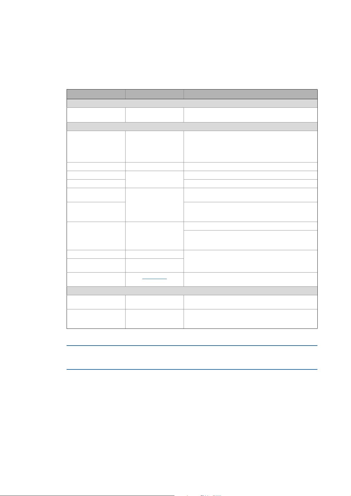
Product series Type designation Version
I/O systems I/O system 1000 From hardware version 1B or software version 10
Screenshots/application examples
All screenshots in this documentation are application examples. Depending on the firmware
version of the device and the software version of the installed »PLC Designer«, the screenshots in
this documentation may differ from the screen display.
Document history
Version Description
1.2 11/2012 TD05 General revision of the document structure, extension of the module overview by
1.1 07/2012 TD06 Extended by the "Commissioning of a counter" example
1.0 11/2011 TD11 First edition
I/O compound modules EPM-S406 and EPM-S408.
Tip!
Information and tools all about the Lenze products can be found in the Internet:
http://www.Lenze.com
Download
Lenze · I/O system 1000 · commissioning guidelines for the PLC Designer · DMS 1.2 EN · 11/2012 · TD05 3
Page 4
1 About this documentation
1.1 Conventions used
_ _ _ _ _ _ _ _ _ _ _ _ _ _ _ _ _ _ _ _ _ _ _ _ _ _ _ _ _ _ _ _ _ _ _ _ _ _ _ _ _ _ _ _ _ _ _ _ _ _ _ _ _ _ _ _ _ _ _ _ _ _ _ _
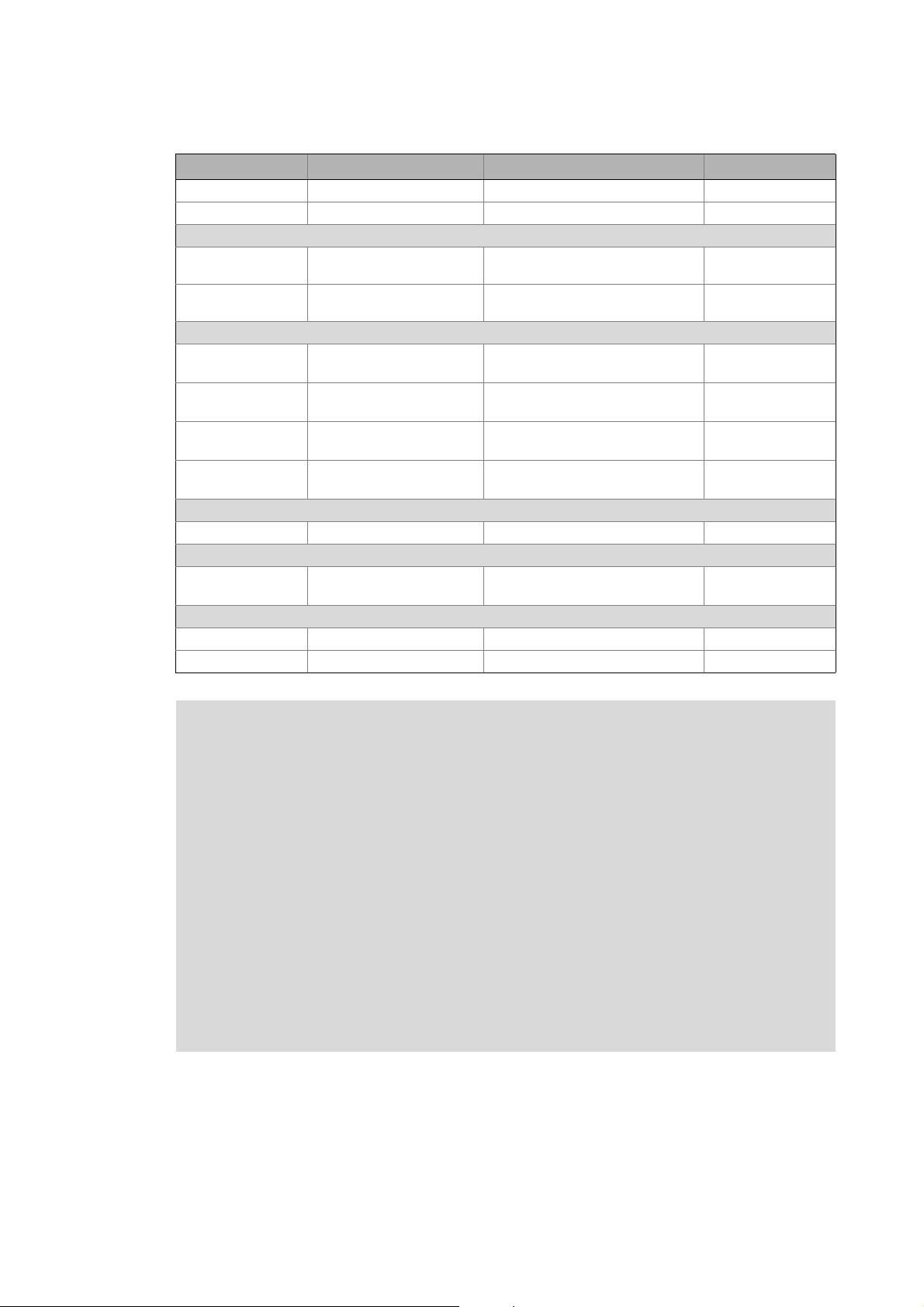
1.1 Conventions used
This documentation uses the following conventions for the distinction between different types of
information:
Type of information Highlighting Examples/notes
Numbers
Decimal separator Point Generally the decimal point is used.
Example: 1234.56
Text
Version info Text colour blue All pieces of information that only apply to or from a certain
Program name » « The »PLC Designer« Lenze PC software...
Window Italics The Message window... / The Options ... dialog box
Variable name By setting bEnable to TRUE...
Control element Bold The OK... button / The Copy... command / The Properties...
Sequence of menu
commands
Shortcut <bold> Use <F1> to open the online help.
Program code Courier
Keyword Courier bold
controller software version are identified accordingly in this
documentation.
Example: This function extension is available from software
version V3.0 onwards!
tab / The Name ... input field
If several commands must be used in sequence to carry out a
function, the individual commands are separated by an
arrow: Select File
If a shortcut is required for a command to be executed, a "+"
has been put between the key identifiers: With
<Shift>+<ESC> ...
IF var1 < var2 THEN
a = a + 1
END IF
Open to...
Hyperlink Underlined
Symbols
Page reference ( 4) Optically highlighted reference to another page. In this
Step-by-step instructions
Highlighted reference to another topic. In this online
documentation activated with a mouse-click.
online documentation activated by means of a mouse-click.
Step-by-step instructions are marked by a pictograph.
All data that only apply to or from a certain software version of the I/O system are identified
accordingly in this documentation.
4
Lenze · I/O system 1000 · commissioning guidelines for the PLC Designer · DMS 1.2 EN · 11/2012 · TD05
Page 5
1 About this documentation
1.2 Terminology used
_ _ _ _ _ _ _ _ _ _ _ _ _ _ _ _ _ _ _ _ _ _ _ _ _ _ _ _ _ _ _ _ _ _ _ _ _ _ _ _ _ _ _ _ _ _ _ _ _ _ _ _ _ _ _ _ _ _ _ _ _ _ _ _
1.2 Terminology used
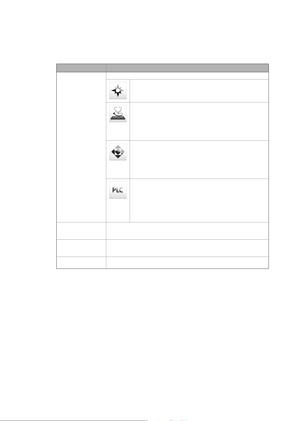
Term Meaning
Engineering tools Software solutions for easy engineering in all phases
»EASY Navigator« – ensures easy operator guidance
• All practical Lenze engineering tools at a glance
• Tools can be selected quickly
• The clarity makes the engineering process easy right from the start
»EASY Starter« – easy-to-use tool for service technicians
• Especially designed for commissioning and maintaining Lenze devices
• Graphic surface with very few icons
• Easy to run online diagnostics, set parameters and perform
commissioning
• No risk of accidentally changing an application
• Loading off-the-shelf applications onto the device
»Engineer« – multi-device engineering
• For all products in our L-force portfolio
• Practical user interface
• Graphic interfaces make it easy to navigate
• Can be applied in every phase of a project (project planning,
commissioning, production)
• Parameter setting and configuration
»PLC Designer« – for programming processes
• The ability to create your own programs
• The ability to program logic & motion in accordance with IEC 61131-3
(AWL, KOP, FUP, ST, AS and CFC-Editor), based on CoDeSys V3
• Function blocks certified according to PLCopen Part 1 + 2
• Graphic DIN 66025 editor (G code) with DXF import
• Integrated visualisation for simple presentation of processes
• All important information at a glance during commissioning
L-force Controller The L-force Controller is the central component of the automation system, controlling
the Logic and Motion functionalities (by means of the runtime software).
The L-force Controller uses the fieldbus to communicate with the field devices.
Engineering PC The Engineering PC with the installed engineering tools serve to configure and
parameterise the system.
The Engineering PC communicates with the L-force Controller via Ethernet.
EtherCAT® EtherCAT® is a registered trademark and patented technology licenced by the Beckhoff
Automation GmbH, Germany.
Lenze · I/O system 1000 · commissioning guidelines for the PLC Designer · DMS 1.2 EN · 11/2012 · TD05 5
Page 6

1 About this documentation
1.3 Definition of notes used
_ _ _ _ _ _ _ _ _ _ _ _ _ _ _ _ _ _ _ _ _ _ _ _ _ _ _ _ _ _ _ _ _ _ _ _ _ _ _ _ _ _ _ _ _ _ _ _ _ _ _ _ _ _ _ _ _ _ _ _ _ _ _ _
1.3 Definition of notes used
The following signal words and icons are used in this documentation to indicate dangers and
important information:
Safety instructions
Structure of safety instructions
Danger!
(characterises the type and severity of danger)
Note
(describes the danger and gives information about how to prevent dangerous
situations)
Pictograph Signal word Meaning
Danger! Danger of personal injuries through dangerous electrical voltage
Danger! Danger of personal injury through a general source of danger
Stop! Danger of damage to material assets
Application notes
Pictograph Signal word Meaning
Note! Important note to ensure troublefree operation
Reference to an imminent danger that may result in death or serious personal
injury if the corresponding measures are not taken.
Reference to an imminent danger that may result in death or serious personal
injury if the corresponding measures are not taken.
Reference to a possible danger that may result in damage to material assets if
the corresponding measures are not taken.
Tip! Useful tip for easy handling
Reference to other documentations
6
Lenze · I/O system 1000 · commissioning guidelines for the PLC Designer · DMS 1.2 EN · 11/2012 · TD05
Page 7
2 System and product description
2.1 The "Controller-based automation" system
_ _ _ _ _ _ _ _ _ _ _ _ _ _ _ _ _ _ _ _ _ _ _ _ _ _ _ _ _ _ _ _ _ _ _ _ _ _ _ _ _ _ _ _ _ _ _ _ _ _ _ _ _ _ _ _ _ _ _ _ _ _ _ _
2 System and product description
2.1 The "Controller-based automation" system
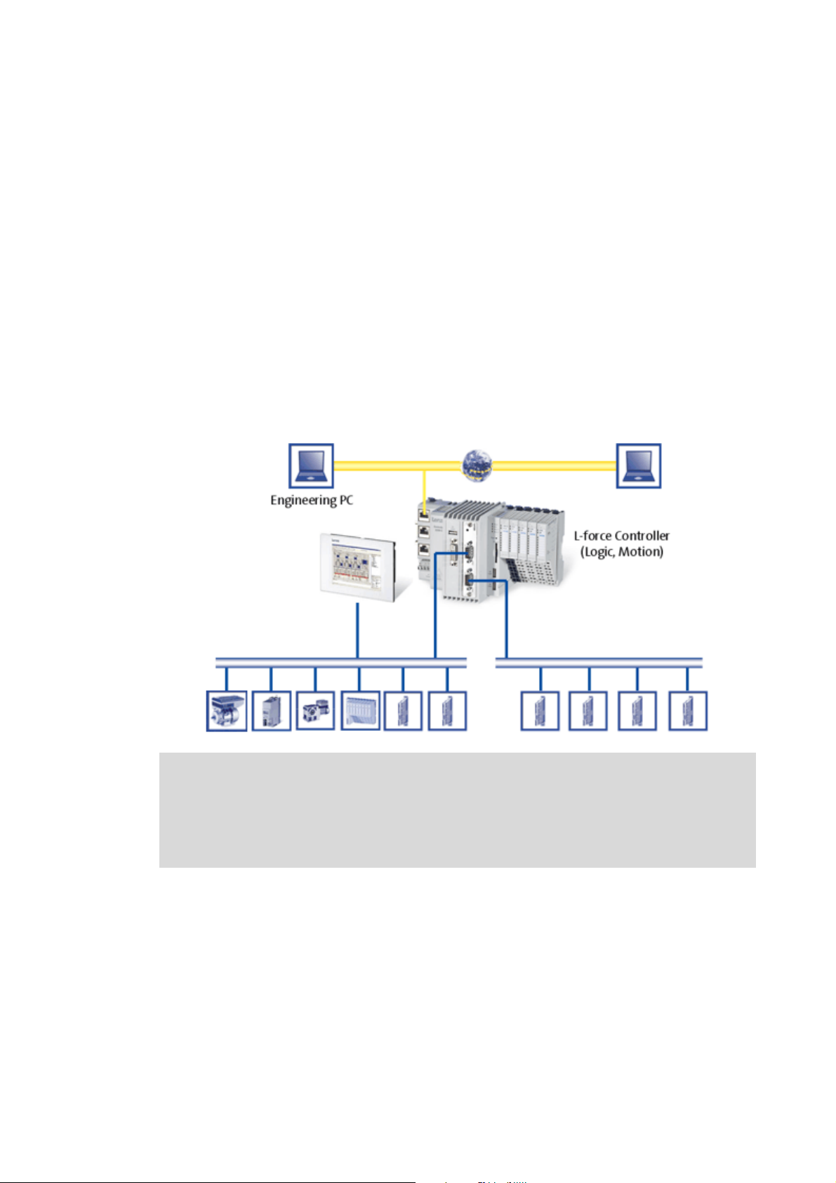
Central control technology is increasingly finding its way into automation technology. Due to their
scaling possibilities and the possibilities to combine visualisation and control in one device,
industrial PCs have clear advantages for many applications.
The L-force Controllers are available with the following software programs:
• L-force Controller as control system
• L-force Controller as visualisation system (depending on the model, an additional panel may be
required)
• L-force Controller as component, on request with operating system, without any further
software
The "Controller-based automation" system enables the central control of Logic and Motion systems.
Further information on parameter setting and configuration of the individual bus
systems can be found in the following communication manuals:
• CANopen control technology - Commissioning & Configuration
• EtherCAT control technology - Commissioning & Configuration
• PROFIBUS control technology - Commissioning & Configuration
Lenze · I/O system 1000 · commissioning guidelines for the PLC Designer · DMS 1.2 EN · 11/2012 · TD05 7
Page 8

2 System and product description
2.2 Features of the I/O system 1000
_ _ _ _ _ _ _ _ _ _ _ _ _ _ _ _ _ _ _ _ _ _ _ _ _ _ _ _ _ _ _ _ _ _ _ _ _ _ _ _ _ _ _ _ _ _ _ _ _ _ _ _ _ _ _ _ _ _ _ _ _ _ _ _
Lenze provides coordinated system components:
• L-force Controller as control and visualisation system
• The L-force Controller is the central component of controller-based automation, controlling
the Logic and Motion functionalities by means of the runtime software.
• The L-force Controller uses the fieldbus to communicate with the field devices.
• Engineering tools for the Engineering PC
• The Engineering PC communicates with the L-force Controller via Ethernet.
• The different engineering tools are used to configure and parameterise the system.
•Fieldbuses
•Field devices
2.2 Features of the I/O system 1000
The I/O system 1000 is suitable for the implementation of complex automation applications
consisting of the following components: bus coupler module, I/O compound modules, and
backplane bus.
• Modular system
•Dimensions
• I/O compound module 109×76.5×12.5mm
• Bus coupler module 109 × 76.5 × 48.5 mm
• Mounting on standard DIN rail (35 mm)
• Shield connection to standard metal rail (10 × 3 mm)
• The two-piece structure (separation of electronics and process integration) enables a quick
exchange of modules in the event of service
• Wiring level via spring terminal (max. 1.5 mm²)
• Operation at DC 24 V (DC 20.4 … DC 28.8 V)
• Supply voltage of electronics and process level are separated
• Number of I/O compound modules
• A bus coupler can contain up to 64 modules
• Individual labelling by insertable labels (item designation)
• Electrical wiring diagrams are directly printed on the module
• Electrical isolation to the fieldbus and the process level
• Creation of electrical isolations by power supply modules
8
Lenze · I/O system 1000 · commissioning guidelines for the PLC Designer · DMS 1.2 EN · 11/2012 · TD05
Page 9
2 System and product description
0
64... ...
4
1
2.3 Device architecture
_ _ _ _ _ _ _ _ _ _ _ _ _ _ _ _ _ _ _ _ _ _ _ _ _ _ _ _ _ _ _ _ _ _ _ _ _ _ _ _ _ _ _ _ _ _ _ _ _ _ _ _ _ _ _ _ _ _ _ _ _ _ _ _
2.3 Device architecture
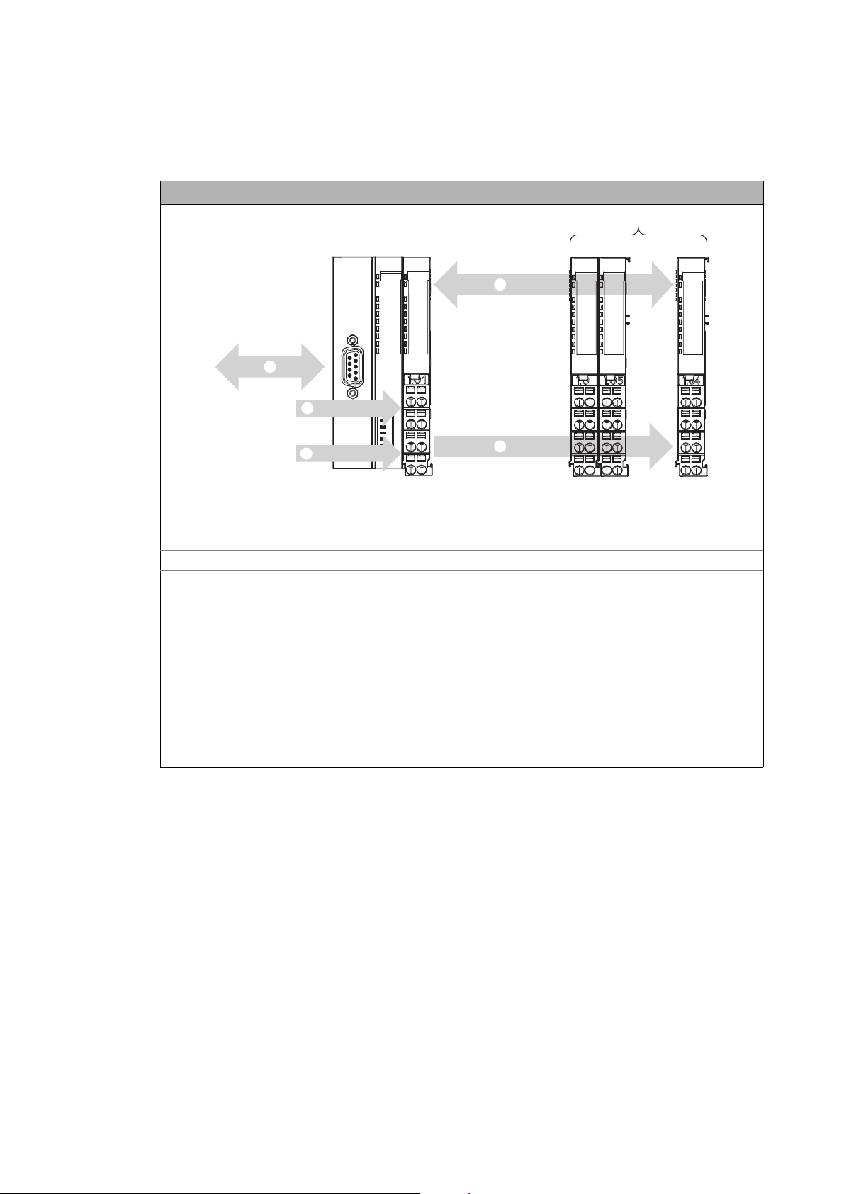
Device architecture of the I/O system 1000
Bus coupler module
•CANopen: EPM-S110
•PROFIBUS: EPM-S120
•EtherCAT: EPM-S130
I/O compound modules, max. 64
n Connection to the bus system (CANopen/EtherCAT)
• CANopen, PROFIBUS: via a 9-pole Sub-D plug (see illustration)
• EtherCAT: RJ45, double
o Internal backplane bus for communication between the bus coupler module and the I/O compound modules
• Side-by-side mounting of the module feet of the I/O compound modules provides for the electrical
connection to the bus coupler module.
p Supply voltage DC 24 V, max. 10 A for consumers at output modules
• Side-by-side mounting of the module feet of the I/O compound modules provides for the electrical
connection to the bus coupler module.
q Supply voltage DC 24 V for the electronics
• Side-by-side mounting of the module feet of the I/O compound modules provides for the electrical
connection to the bus coupler module.
Lenze · I/O system 1000 · commissioning guidelines for the PLC Designer · DMS 1.2 EN · 11/2012 · TD05 9
Page 10

2 System and product description
2.4 Available bus coupler modules
_ _ _ _ _ _ _ _ _ _ _ _ _ _ _ _ _ _ _ _ _ _ _ _ _ _ _ _ _ _ _ _ _ _ _ _ _ _ _ _ _ _ _ _ _ _ _ _ _ _ _ _ _ _ _ _ _ _ _ _ _ _ _ _
2.4 Available bus coupler modules
Type designation Short designation Description Process data
EPM-S110 CANopen CANopen bus coupler module -
EPM-S120 PROFIBUS PROFIBUS bus coupler module -
EPM-S130 EtherCAT EtherCAT bus coupler module -
EPM-S140 PROFINET PROFINET bus coupler module -
EPM-S150 DeviceNet DeviceNet bus coupler module -
EPM-S160 Modbus TCP Modbus TCP bus coupler module -
2.5 Available I/O compound modules
Type designation Short designation Description Process data
Digital-I/O
EPM-S200 DI2, DC 24V 2 digital inputs 2 bits
EPM-S201 DI4, DC 24V 4 digital inputs 4 bits
EPM-S202 DI8, DC 24V 8 digital inputs 8 bits
EPM-S203 DI4, DC 24V 4 digital inputs
• Three-wire conductor connection
EPM-S204 DI2, NPN, DC 24V 2 digital inputs, npn 2 bits
EPM-S205 DI4, NPN, DC 24V 4 digital inputs, npn 4 bits
EPM-S206 DI8, NPN, DC 24V 8 digital inputs, npn 8 bits
EPM-S207 DI2 time stamp, DC 24V 2 digital inputs ENP 8 bytes, writing
EPM-S300 DO2, DC 24V, 0.5A 2 digital outputs, 0.5 A 2 bits
EPM-S301 DO4, DC 24V, 0.5A 4 digital outputs, 0.5 A 4 bits
EPM-S302 DO8, DC 24V, 0.5A 8 digital outputs, 0.5 A 8 bits
EPM-S303 DO2, NPN, DC 24V, 0.5A 2 digital outputs, npn 2 bits
EPM-S304 DO4, NPN, DC 24V, 0.5A 4 digital outputs, npn 4 bits
EPM-S305 DO8, NPN, DC 24V, 0.5A 8 digital outputs, npn 8 bits
EPM-S306 DO2, DC 24V, 2A 2 digital outputs, 2 A 2 bits
EPM-S308 DO2, relay 230V, 3A 2 relay outputs 2 bits
EPM-S309 DO4, DC 24V, 2A 4 digital outputs, 2 A 4 bits
EPM-S310 DO2 time stamp, DC 24V 2 digital outputs, 0.5 A, ENP 8 bytes, reading
Analog I/O
EPM-S400 AI2, 12BIT, DC 0…10V 2 analog inputs, 0 … 10 V DC 4 bytes
EPM-S401 AI4, 12BIT, DC 0…10V 4 analog inputs, 0 … 10 V DC 8 bytes
EPM-S402 AI2, 12BIT, DC 0/4…20mA 2 analog inputs, 0/4 … 20 mA 4 bytes
EPM-S403 AI4, 12BIT, DC 0/4…20mA 4 analog inputs, 0/4 … 20 mA 8 bytes
EPM-S406 AI2, 16BIT, DC +/-10V 2 analog inputs
for voltage measurement ±10 V
EPM-S408 AI2, 16BIT, DC 0/4…20mA 2 analog inputs
for current measurement
EPM-S500 AO2, 12BIT, DC 0…10V 2 analog outputs, 0 … 10 V DC 4 bytes
EPM-S501 AO4, 12BIT, DC 0…10V 4 analog outputs, 0 … 10 V DC 8 bytes
4 bits
2 bytes, writing
4 bytes
4 bytes
10
Lenze · I/O system 1000 · commissioning guidelines for the PLC Designer · DMS 1.2 EN · 11/2012 · TD05
Page 11
2 System and product description
2.5 Available I/O compound modules
_ _ _ _ _ _ _ _ _ _ _ _ _ _ _ _ _ _ _ _ _ _ _ _ _ _ _ _ _ _ _ _ _ _ _ _ _ _ _ _ _ _ _ _ _ _ _ _ _ _ _ _ _ _ _ _ _ _ _ _ _ _ _ _
Type designation Short designation Description Process data
EPM-S502 AO2, 12BIT, DC 0/4…20mA 2 analog outputs, 0/4 … 20 mA 4 bytes
EPM-S503 AO4, 12BIT, DC 0/4…20mA 4 analog outputs, 0/4 … 20 mA 8 bytes
Temperature measurement
EPM-S404 AI2, 16bits, resistor 4 analog inputs
for resistance measurement
EPM-S405 AI2, 16bits, thermo 2 analog inputs
for thermocouple measurement
Numerator
EPM-S600 Counter 1, DC 24V 1 counter 32 bits, 24 V DC
(reading, setting, comparing)
EPM-S601 Counter 2, DC 24V 2 counters 32 bits, 24 V DC
(reading, setting)
EPM-S602 Counter 1, DC 5V 1 counter 32 bits, 5 V DC
(reading, setting)
EPM-S603 Counter 2, DC 24V 2 counters 32 bits, 24 V DC
(reading)
Encoder evaluation
EPM-S604 SSI 1 SSI absolute value encoder 6 bytes, reading
Pulse width modulation
EPM-S620 PWM 2, DC 24V 2 digital outputs, 0.5 A PWM 12 bytes, reading
Communication
EPM-S640 RS232 RS232 module -
EPM-S650 RS422/RS485 RS485 module -
4 bytes
4 bytes
12 bytes, reading
10 bytes, writing
12 bytes, reading
12 bytes, writing
8 bytes, reading
10 bytes, writing
12 bytes, reading
4 bytes, writing
4 bytes, writing
Note!
I/O compound modules EPM-S207/EPM-S310
• If, for instance, motor positions are to be evaluated via these modules, additional
modules with ticker function as e.e.g. EPM-S600 (HTL), EPM-S602 (TTL) or EPM-S604
(SSI) are required for detecting the encoder signals.
• Only if the modules EPM-S207 and EPM-S310 are connected to the backplane bus of
the L-force Controller: The following modules are available in the
"L_SM3_DriveUtil.lib" function library for the I/O system 1000:
• L_SMC_AbortTrigger_FastIO
• L_SMC_TouchProbe_FastIO
• More information can be obtained from the online help for the function library.
I/O compound modules EPM-S640/EPM-S650
• For using the modules EPM-S640 and EPM-S650, the "L_COM_EPMS640" function
library is available.
• More information can be obtained from the online help for the function library.
Lenze · I/O system 1000 · commissioning guidelines for the PLC Designer · DMS 1.2 EN · 11/2012 · TD05 11
Page 12
3 Establish communication
3.1 Establishing communication with the L-force Controller
_ _ _ _ _ _ _ _ _ _ _ _ _ _ _ _ _ _ _ _ _ _ _ _ _ _ _ _ _ _ _ _ _ _ _ _ _ _ _ _ _ _ _ _ _ _ _ _ _ _ _ _ _ _ _ _ _ _ _ _ _ _ _ _
3 Establish communication
This chapter describes how to establish a communication between the Engineering PC with the
installed »PLC Designer« and the I/O system 1000.
The system manual for the I/O system 1000 contains detailed information on the
communication via the respective fieldbus (CANopen, EtherCAT, ...).
3.1 Establishing communication with the L-force Controller
• Connect the Engineering PC with the L-force Controller via a network cable, as the »PLC
Designer« accesses the L-force Controller via Ethernet.
• Make the IP settings with the »PLC Designer«.
Note!
Please observe the following predefined IP addresses when commissioning your IPC for
the first time:
• Engineering PC: 192.168.5.100
• L-force Controller: 192.168.5.99
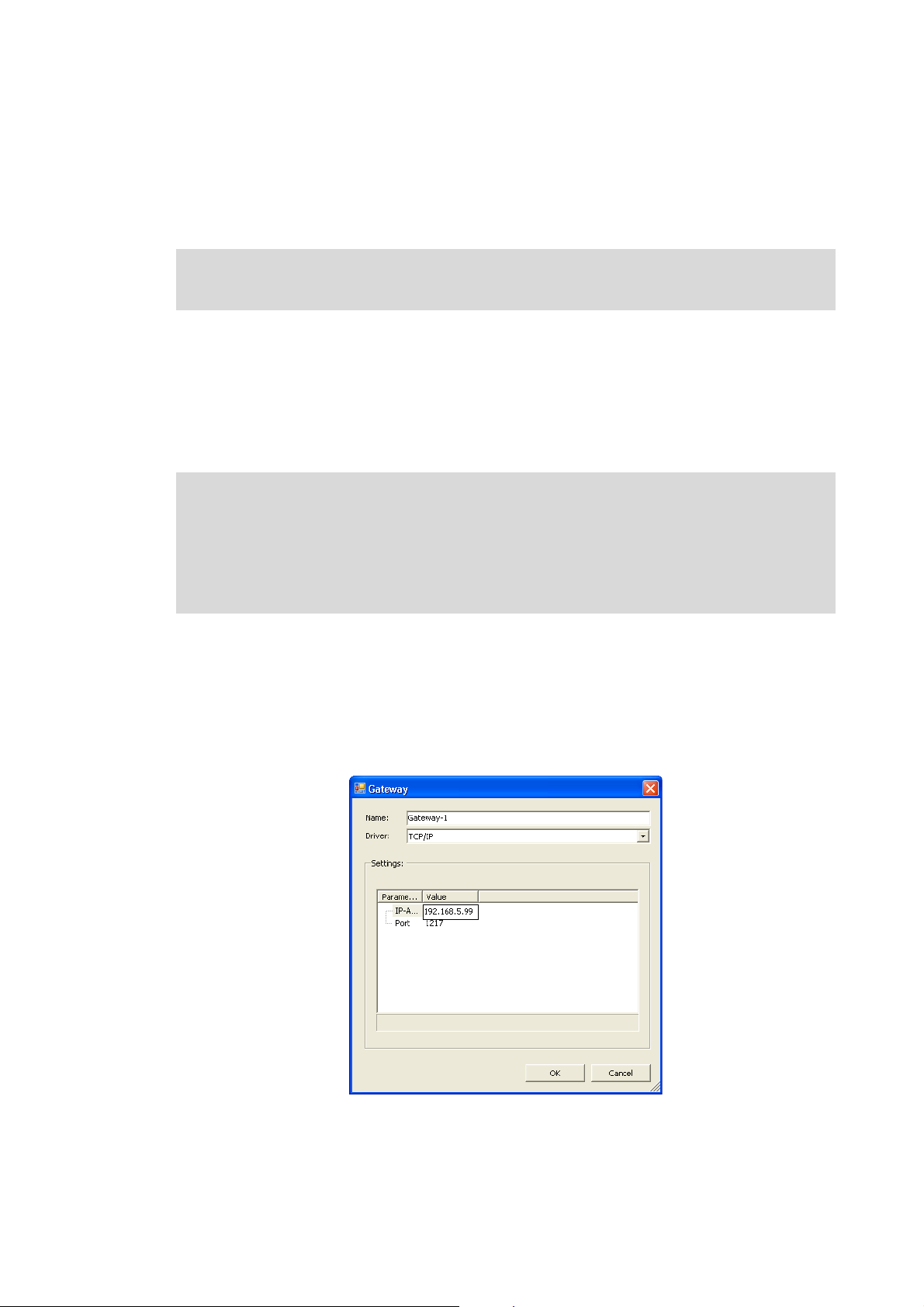
How to check the communication settings:
1. Double-click the L-force Controller in the Device view to open the settings and properties of
the device in the Editor view.
2. Make the desired settings on the Communication settings tab.
•Click the Add gateway button to insert a gateway.
• Enter the desired IP address of the L-force Controller.
12
3. Click OK to add the L-force Controller as gateway.
Lenze · I/O system 1000 · commissioning guidelines for the PLC Designer · DMS 1.2 EN · 11/2012 · TD05
Page 13
3 Establish communication
3.2 Establish a connection between L-force Controller and I/O system 1000
_ _ _ _ _ _ _ _ _ _ _ _ _ _ _ _ _ _ _ _ _ _ _ _ _ _ _ _ _ _ _ _ _ _ _ _ _ _ _ _ _ _ _ _ _ _ _ _ _ _ _ _ _ _ _ _ _ _ _ _ _ _ _ _
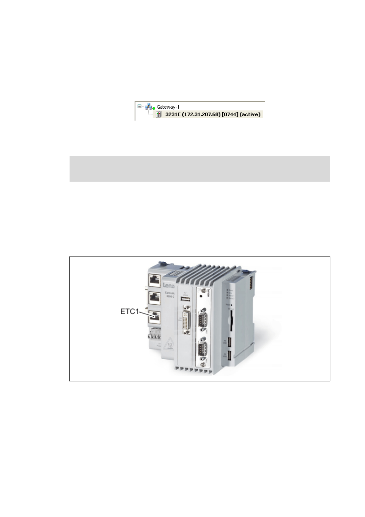
4. Double-click the channel to be set as active path for control below the gateway in the
Device view.
• Thus, all communication actions directly refer to this channel.
• The channel currently active is displayed in bold in the Device view and marked with the
"(active)" addition:
• A channel represented in italics is set as active path but has not been identified at the last
network scan.
Further information can be found in the following documentation:
• L-force Controller - Parameter setting & configuration
3.2 Establish a connection between L-force Controller and I/O system 1000
For a connection via EtherCAT:
• Connect the RJ45 port on the EtherCAT bus coupler module (EPM-S130) to the L-force Controller
using a network cable.
• The I/O system 1000 is supplied with DC 24 V for the control electronics.
[3-1] The EtherCAT interface at the L-force Controller 3231 C
Lenze · I/O system 1000 · commissioning guidelines for the PLC Designer · DMS 1.2 EN · 11/2012 · TD05 13
Page 14
4 Mapping the real station structure in the »PLC Designer«
4.1 Creating a new project in the »PLC Designer«
_ _ _ _ _ _ _ _ _ _ _ _ _ _ _ _ _ _ _ _ _ _ _ _ _ _ _ _ _ _ _ _ _ _ _ _ _ _ _ _ _ _ _ _ _ _ _ _ _ _ _ _ _ _ _ _ _ _ _ _ _ _ _ _
4 Mapping the real station structure in the »PLC Designer«
4.1 Creating a new project in the »PLC Designer«
You can create a new project in the »PLC Designer« without having to establish an online
connection. After having configured the project, go online with the I/O system 1000 to transfer
parameters.
How to create a new project in the »PLC Designer«:
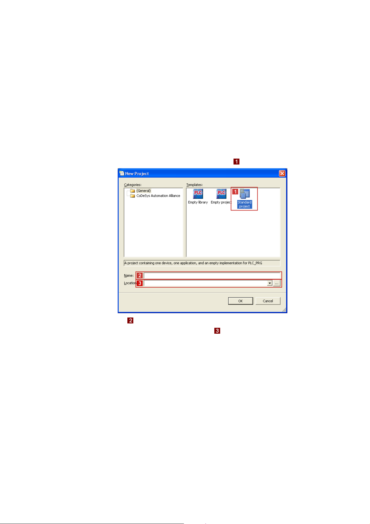
1. Select menu command FileNew project to create a new »PLC Designer« project.
2. Go to the New project dialog window and select the "Standard project" template.
• Go to the Name input field and assign a name for the »PLC Designer« project.
• Select the desired memory location under Location.
3. Confirm the entries by clicking OK.
14
Lenze · I/O system 1000 · commissioning guidelines for the PLC Designer · DMS 1.2 EN · 11/2012 · TD05
Page 15

4 Mapping the real station structure in the »PLC Designer«
4.1 Creating a new project in the »PLC Designer«
_ _ _ _ _ _ _ _ _ _ _ _ _ _ _ _ _ _ _ _ _ _ _ _ _ _ _ _ _ _ _ _ _ _ _ _ _ _ _ _ _ _ _ _ _ _ _ _ _ _ _ _ _ _ _ _ _ _ _ _ _ _ _ _
4. Go to the Standard project dialog window and select the "L-force Controller 3200 C Logic
(Lenze)" in the Device selection list.
In the PLC_PRG in selection list, you can additionally select a programming language:
• Sequential function chart (SFC)
• Instruction list (IL)
• Continuous function chart (CFC)
• Function block diagram (FBD)
• Ladder diagram (LD)
• Structured text (ST)
5. Confirm the selection by clicking OK.
Next steps:
The following chapters describe by means of examples how to add the available I/O system to the
device view of the »PLC Designer« depending on the fieldbus used:
Configuring the I/O modules at the backplane bus of the L-force Controller
Configuring I/O modules on the EtherCAT bus coupler module
Configuring I/O modules on the CANopen bus coupler module
Lenze · I/O system 1000 · commissioning guidelines for the PLC Designer · DMS 1.2 EN · 11/2012 · TD05 15
Page 16

4 Mapping the real station structure in the »PLC Designer«
4.2 Configuring the I/O modules at the backplane bus of the L-force Controller
_ _ _ _ _ _ _ _ _ _ _ _ _ _ _ _ _ _ _ _ _ _ _ _ _ _ _ _ _ _ _ _ _ _ _ _ _ _ _ _ _ _ _ _ _ _ _ _ _ _ _ _ _ _ _ _ _ _ _ _ _ _ _ _
4.2 Configuring the I/O modules at the backplane bus of the L-force Controller
The L-force Controller consists of the following components:
• I/O bus coupler module: controller with a PLC control in the form of a soft PLC.
• I/O compound modules: Up to 64 modules which are connected to the controller via the Lenze
backplane bus.
[4-1] Schematic hardware installation with added I/O compound modules
In order to be able to access the modules by means of a PLC program (reading input signals and
writing output signals), the real station layout, i.e. the physical arrangement of the I/O compound
modules in the device view of the »PLC Designer«:
[4-2] Example: Mapping of the physical topology (module 1 to module 7) in the device view in the »PLC Designer«
16
Lenze · I/O system 1000 · commissioning guidelines for the PLC Designer · DMS 1.2 EN · 11/2012 · TD05
Page 17

4 Mapping the real station structure in the »PLC Designer«
4.2 Configuring the I/O modules at the backplane bus of the L-force Controller
_ _ _ _ _ _ _ _ _ _ _ _ _ _ _ _ _ _ _ _ _ _ _ _ _ _ _ _ _ _ _ _ _ _ _ _ _ _ _ _ _ _ _ _ _ _ _ _ _ _ _ _ _ _ _ _ _ _ _ _ _ _ _ _
The following step-by-step instructions describe by means of an example the manual
the available station layout in the device view of the »PLC Designer».
Tip!
When an online connection has been established to the L-force Controller, you can also
start an automatic search to I/O compound modules available on the backplane bus of the
L-force Controller by executing the Search devices... command in the context menu of the
"I_O_Module_Coupler.
How to map the station layout in the device view of the »PLC Designer»:
1. Go to the context menu of the "I_O_Module_Coupler" and execute the Add device...
command:
mapping of
2. Select the physically fist I/O compound module in the Add device dialog box (for this
example, an "EPM-S200" has been selected):
3. Click Add device to add the selected device to the "I_O_Module_Coupler".
•The Add device dialog box remains open.
Lenze · I/O system 1000 · commissioning guidelines for the PLC Designer · DMS 1.2 EN · 11/2012 · TD05 17
Page 18

4 Mapping the real station structure in the »PLC Designer«
4.2 Configuring the I/O modules at the backplane bus of the L-force Controller
_ _ _ _ _ _ _ _ _ _ _ _ _ _ _ _ _ _ _ _ _ _ _ _ _ _ _ _ _ _ _ _ _ _ _ _ _ _ _ _ _ _ _ _ _ _ _ _ _ _ _ _ _ _ _ _ _ _ _ _ _ _ _ _
4. Add all other available I/O compound modules of the device view in the same way.
• Exemplary representation:
5. Click Close to close the Add device dialog box again.
Tip!
• With a correct configuration and after going online and starting the PLC, all modules in
the device view are marked with the symbol.
• In the event of an error, i.e. if the configuration deviates from the physical arrangement,
the corresponding modules are marked with the symbol.
18
Lenze · I/O system 1000 · commissioning guidelines for the PLC Designer · DMS 1.2 EN · 11/2012 · TD05
Page 19
4 Mapping the real station structure in the »PLC Designer«
4.3 Configuring I/O modules on the EtherCAT bus coupler module
_ _ _ _ _ _ _ _ _ _ _ _ _ _ _ _ _ _ _ _ _ _ _ _ _ _ _ _ _ _ _ _ _ _ _ _ _ _ _ _ _ _ _ _ _ _ _ _ _ _ _ _ _ _ _ _ _ _ _ _ _ _ _ _
4.3 Configuring I/O modules on the EtherCAT bus coupler module
Note!
Observe the following conditions before creating an EtherCAT configuration in the »PLC
Designer«:
• The sequence of the EtherCAT slaves in the device view has to correspond to the
physical order of the EtherCAT topology.
• For a proper function, do not use any end terminals when establishing the system
configuration in the device view.
• Select cycle times of 1 ... 10 ms according to the technical data.
The following step-by-step instructions describe by means of an example the manual mapping of
the available station layout in the device view of the »PLC Designer».
Tip!
When an online connection has been established to the L-force Controller, you can also
start an automatic search for available devices via fieldbus scan by executing the Search
devices... command after adding the EtherCAT master (step 3) in the context menu of the
EtherCAT master.
How to map the station layout in the device view of the »PLC Designer»:
Adding the EtherCAT master
1. Go to the context menu of the L-force Controller and execute the Add device... command:
2. Select the "EtherCAT master" device in the Add device dialog box:
Lenze · I/O system 1000 · commissioning guidelines for the PLC Designer · DMS 1.2 EN · 11/2012 · TD05 19
Page 20

4 Mapping the real station structure in the »PLC Designer«
4.3 Configuring I/O modules on the EtherCAT bus coupler module
_ _ _ _ _ _ _ _ _ _ _ _ _ _ _ _ _ _ _ _ _ _ _ _ _ _ _ _ _ _ _ _ _ _ _ _ _ _ _ _ _ _ _ _ _ _ _ _ _ _ _ _ _ _ _ _ _ _ _ _ _ _ _ _
3. Click Add device to add the selected device to the L-force Controller.
•The Add device dialog box remains open.
Adding the EtherCAT bus coupler module (slave) to the EtherCAT master
4. Select the "EtherCAT_Master" device in the device view:
5. Now select the "EPM-S130" device (EtherCAT bus coupler module) in the still opened Add
device dialog box.
6. Click Add device to add the selected device to the EtherCAT master.
•The Add device dialog box remains open.
Adding I/O compound modules to the EtherCAT bus coupler module
7. Select the "EPM_S130" device in the device view:
8. Select the physically first I/O compound module in the still opened Add device dialog box
and add it by clicking Add device in the device view.
20
Lenze · I/O system 1000 · commissioning guidelines for the PLC Designer · DMS 1.2 EN · 11/2012 · TD05
Page 21

4 Mapping the real station structure in the »PLC Designer«
4.3 Configuring I/O modules on the EtherCAT bus coupler module
_ _ _ _ _ _ _ _ _ _ _ _ _ _ _ _ _ _ _ _ _ _ _ _ _ _ _ _ _ _ _ _ _ _ _ _ _ _ _ _ _ _ _ _ _ _ _ _ _ _ _ _ _ _ _ _ _ _ _ _ _ _ _ _
9. Add all other available I/O compound modules of the device view in the same way.
• Exemplary respresentation:
10. Click Close to close the Add device dialog box again.
Tip!
• With a correct configuration and after going online and starting the PLC, all modules in
the device view are marked with the symbol.
• In the event of an error, i.e. if the configuration deviates from the physical arrangement,
the corresponding modules ar marked with the symbol.
Lenze · I/O system 1000 · commissioning guidelines for the PLC Designer · DMS 1.2 EN · 11/2012 · TD05 21
Page 22
4 Mapping the real station structure in the »PLC Designer«
4.4 Configuring I/O modules on the CANopen bus coupler module
_ _ _ _ _ _ _ _ _ _ _ _ _ _ _ _ _ _ _ _ _ _ _ _ _ _ _ _ _ _ _ _ _ _ _ _ _ _ _ _ _ _ _ _ _ _ _ _ _ _ _ _ _ _ _ _ _ _ _ _ _ _ _ _
4.4 Configuring I/O modules on the CANopen bus coupler module
Note!
An L-force Controller in the CANopen network is to be configured in the »PLC Designer«
since the complete configuration is written to the connected slaves when the L-force
Controller is started. During this process, previous settings in slaves are overwritten.
The following step-by-step instructions describe by means of an example the manual mapping of
the available station layout in the device view of the »PLC Designer».
Tip!
When an online connection has been established to the L-force Controller, you can also
start an automatic search for available devices via fieldbus scan by executing the Search
devices... command after adding the CANopen master (step 6) in the context menu of the
CANopen master.
How to map the station layout in the device view of the »PLC Designer»:
Adding the CANbus
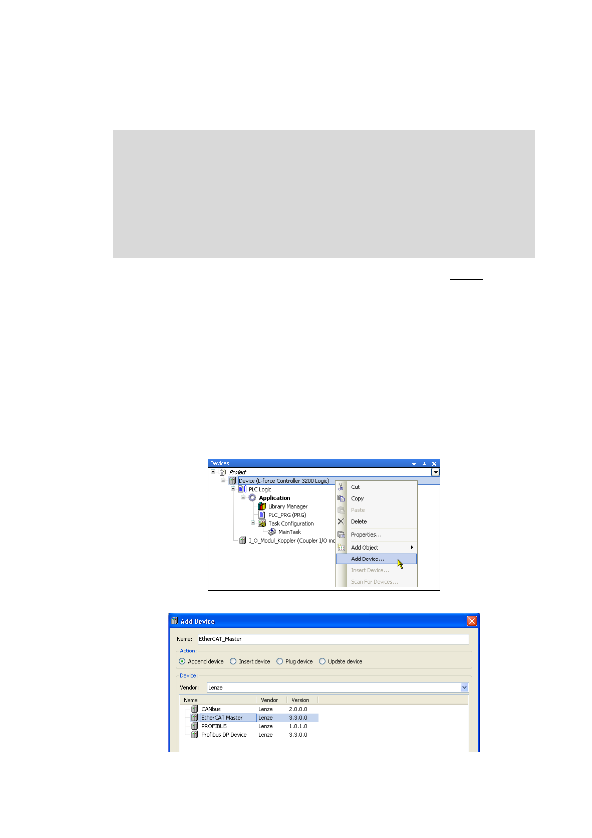
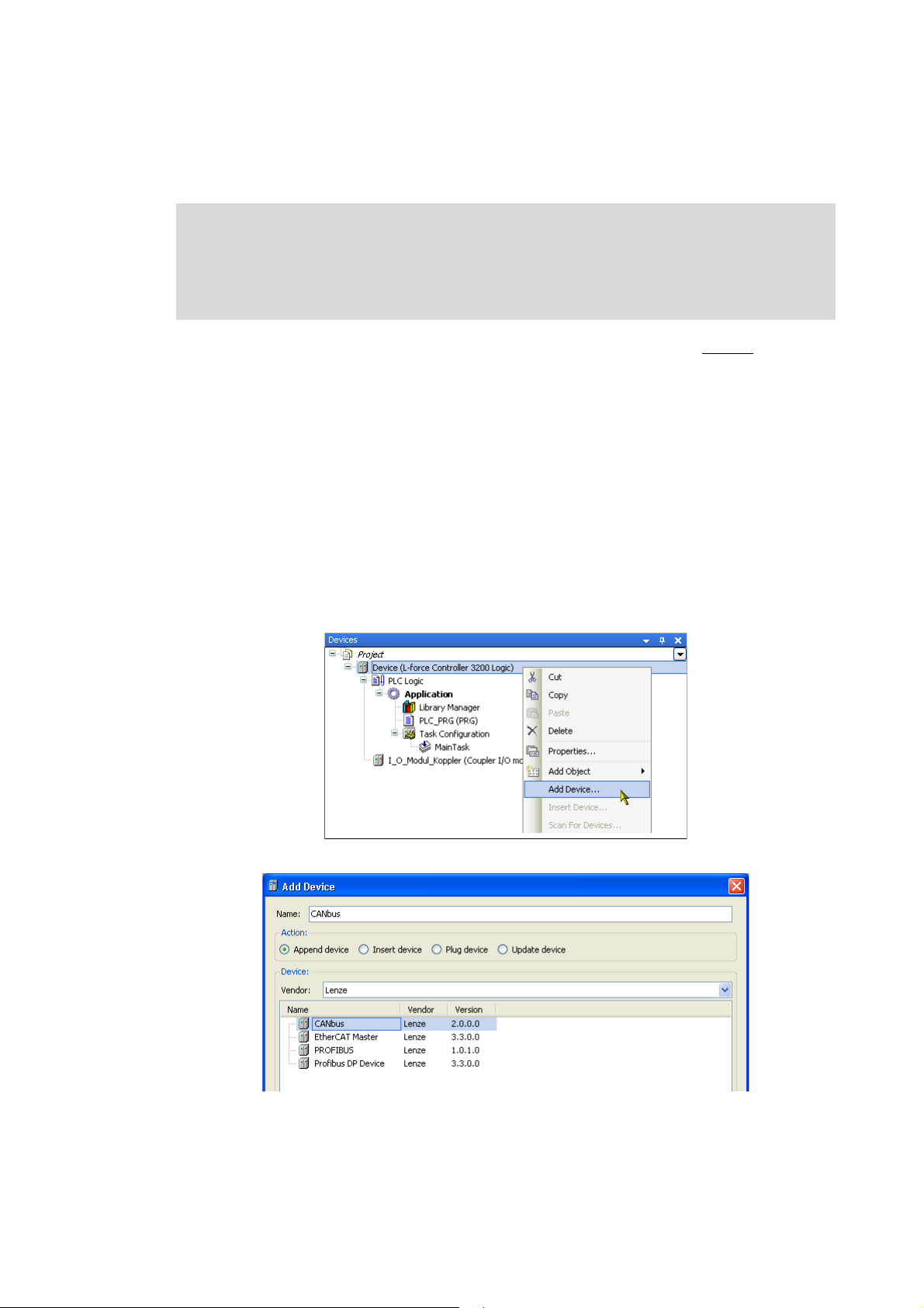
1. Go to the context menu of the L-force Controller and execute the Add device... command:
2. Select the "CANbus" device in the Add device dialog box:
22
3. Click Add device to add the selected device to the L-force Controller.
•The Add device dialog box remains open.
Lenze · I/O system 1000 · commissioning guidelines for the PLC Designer · DMS 1.2 EN · 11/2012 · TD05
Page 23
4 Mapping the real station structure in the »PLC Designer«
4.4 Configuring I/O modules on the CANopen bus coupler module
_ _ _ _ _ _ _ _ _ _ _ _ _ _ _ _ _ _ _ _ _ _ _ _ _ _ _ _ _ _ _ _ _ _ _ _ _ _ _ _ _ _ _ _ _ _ _ _ _ _ _ _ _ _ _ _ _ _ _ _ _ _ _ _
Adding the CANopen Manager to the CANbus
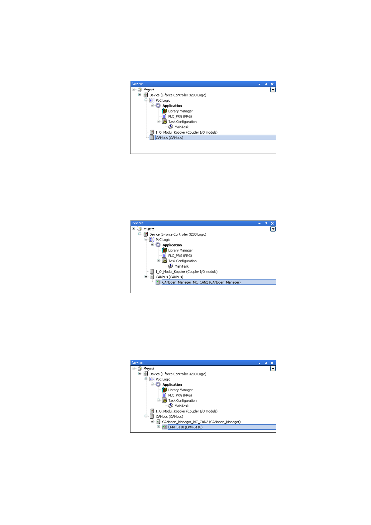
4. Select the "CANbus" device in the device view:
5. Now select the"CANopen Manager MC-CAN2" device in the still opened add device dialog
box.
6. Click Add device to add the selected device to the CANbus.
•The Add device dialog box remains open.
Adding the CANopen bus coupler module (slave) to the CANopen Manager
7. Select the "CANopen_Manager_MC_CAN2" device in the device view:
8. Now select the "EPM-S110" device (CANopen bus coupler module) in the still opened Add
device dialog box.
9. Click Add device to add the selected device to the CANopen Manager.
•The Add device dialog box remains open.
Adding I/O compound modules to the CANopen bus coupler module
10. Select the "EPM_S110" device in the device view:
11. Select the physically first I/O compound module in the still opened Add device dialog box
and add it by clicking Add device in the device view.
Lenze · I/O system 1000 · commissioning guidelines for the PLC Designer · DMS 1.2 EN · 11/2012 · TD05 23
Page 24
4 Mapping the real station structure in the »PLC Designer«
4.4 Configuring I/O modules on the CANopen bus coupler module
_ _ _ _ _ _ _ _ _ _ _ _ _ _ _ _ _ _ _ _ _ _ _ _ _ _ _ _ _ _ _ _ _ _ _ _ _ _ _ _ _ _ _ _ _ _ _ _ _ _ _ _ _ _ _ _ _ _ _ _ _ _ _ _
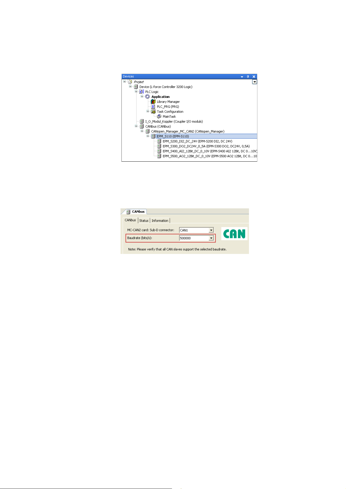
12. Add all other available I/O compound modules of the device view in the same way.
• Exemplary respresentation:
13. Click Close to close the Add device dialog box again.
Setting the CAN baud rate
14. Click the "CANbus" device in the device view to open its settings.
15. Set the baud rate on the CANbus tab:
Note!
• The baud rate set in the »PLC Designer« overwrites the baud rate set for the field devices
via »WebConfig«/»EASY Starter«/»Engineer«/»Global Drive Control«.
• In a CANopen network, set the same baud rate for all nodes.
24
Lenze · I/O system 1000 · commissioning guidelines for the PLC Designer · DMS 1.2 EN · 11/2012 · TD05
Page 25
4 Mapping the real station structure in the »PLC Designer«
4.4 Configuring I/O modules on the CANopen bus coupler module
_ _ _ _ _ _ _ _ _ _ _ _ _ _ _ _ _ _ _ _ _ _ _ _ _ _ _ _ _ _ _ _ _ _ _ _ _ _ _ _ _ _ _ _ _ _ _ _ _ _ _ _ _ _ _ _ _ _ _ _ _ _ _ _
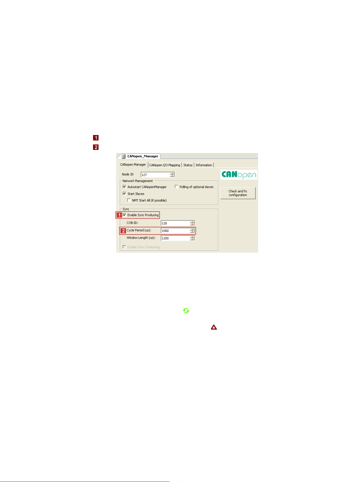
Setting sync generation
Sync generation is required if ...
• at least one PDO with sync-controlled processing is used on the bus;
• the applications are to run in synchronism in several field devices;
• Motion devices are to be operated on the fieldbus.
Activate the sync generation:
16. Double-click the "CANopen_Manager_MC_CAN2" device in the device view to open its
settings.
17. On the CANopen_Manager tab:
• Activate sync generation option.
• Set sync cycle time in the Cycle Period input field.
Tip!
• With a correct configuration and after going online and starting the PLC, all modules in
the device view are marked with the symbol.
• In the event of an error, i.e. if the configuration deviates from the physical arrangement,
the corresponding modules ar marked with the symbol.
Lenze · I/O system 1000 · commissioning guidelines for the PLC Designer · DMS 1.2 EN · 11/2012 · TD05 25
Page 26

4 Mapping the real station structure in the »PLC Designer«
4.4 Configuring I/O modules on the CANopen bus coupler module
_ _ _ _ _ _ _ _ _ _ _ _ _ _ _ _ _ _ _ _ _ _ _ _ _ _ _ _ _ _ _ _ _ _ _ _ _ _ _ _ _ _ _ _ _ _ _ _ _ _ _ _ _ _ _ _ _ _ _ _ _ _ _ _
4.4.1 Special features of the CANopen bus coupler module (EPM-S110)
Note!
Before inserting I/O compound modules below a CANopen bus coupler module (EPMS110) in the »PLC Designer«, close the tab to the EPM-S110.
• When inserting I/O compound modules while the tab is open, no
displayed for the modules.
• When all I/O compound module are inserted, the tab to the EPM-S110 can be opened
again.
When the counter modules (EPM-S600 ... S604) at the CANopen bus coupler module (EPM-S110) are
used, the following sequence has to be complied with during configuration.
How to configure the EPM-S600 ... S604 counter modules:
1. Add CANopen bus coupler module (EPM-S110) to the device view.
I/O image is
2. Add I/O discs and counter discs.
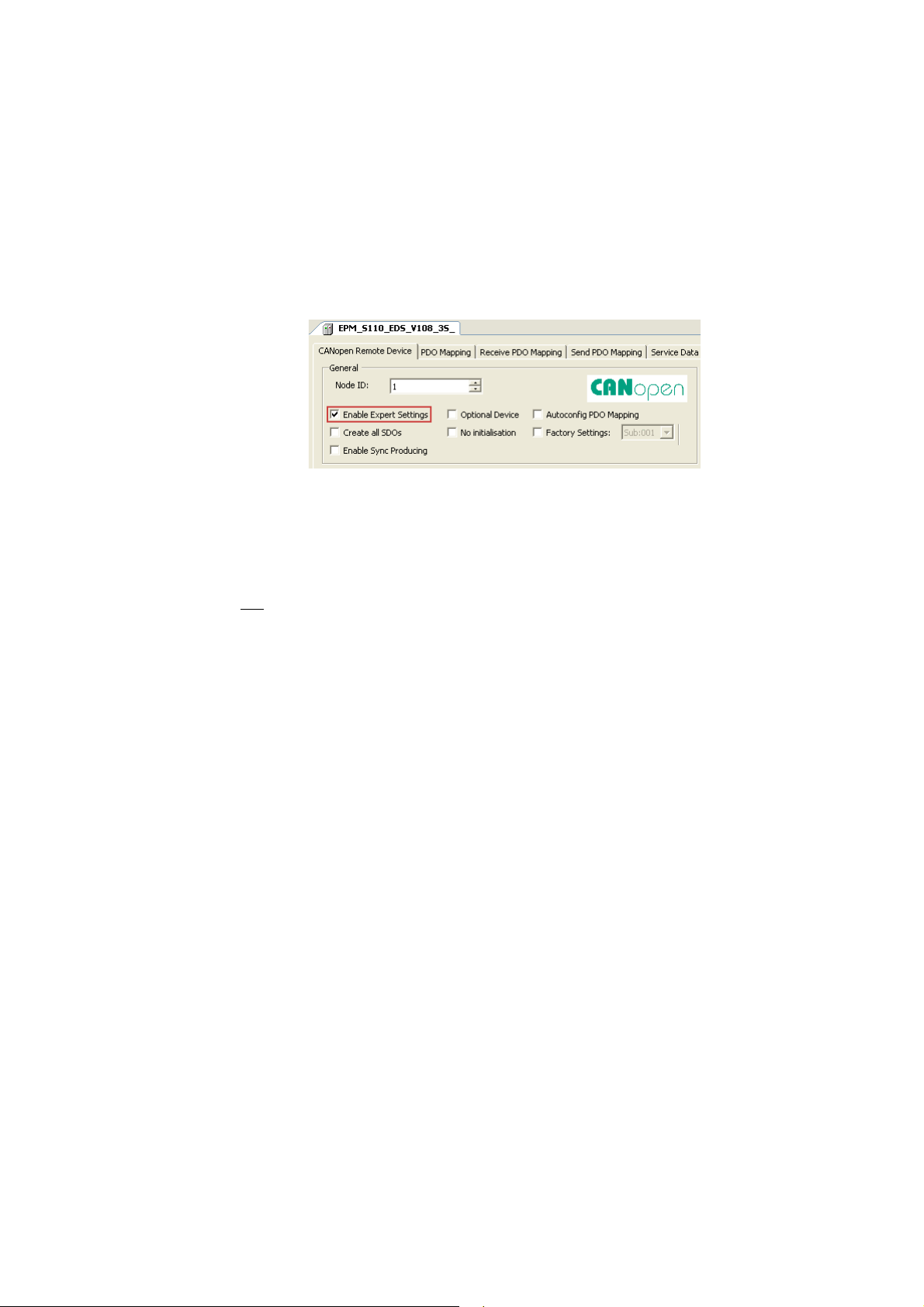
3. Click the "EPM_S110" device in the device view S110to open its settings.
4. On the CANopen Remote Device tab:
• Activate the Expert settings option.
• Deactivate the Autoconfig. PDO Mapping option.
5. Execute the menu command WindowClose All Editors.
26
Lenze · I/O system 1000 · commissioning guidelines for the PLC Designer · DMS 1.2 EN · 11/2012 · TD05
Page 27

4 Mapping the real station structure in the »PLC Designer«
4.4 Configuring I/O modules on the CANopen bus coupler module
_ _ _ _ _ _ _ _ _ _ _ _ _ _ _ _ _ _ _ _ _ _ _ _ _ _ _ _ _ _ _ _ _ _ _ _ _ _ _ _ _ _ _ _ _ _ _ _ _ _ _ _ _ _ _ _ _ _ _ _ _ _ _ _
Add the PDO configuration for the counter discs.
The following example uses a send PDO and a mapping element to describe the basic
configuration process.
• Proceed accordingly when configuring the transmit PDOs (Send PDO Mapping tab).
6. Click the "EPM_S110" device in the device view S110to open its settings.
7. Click Add PDO... on the Receive PDO Mapping to add receive PDOs.
• Depending on the counter discs used, one or several PDOs must be added in send and
receive direction.
• Please refer to the module documentation to see which additional elements of the
process image of the counter modules are required for operation.
8. Select added PDOs and click Add Mapping....
• Select the corresponding settings in the dialog box that appears.
Note!
If Autoconfig. PDO Mapping (see step 3) is reactivated after adding the manual
configuration, the entire configuration that has been added manually will be deleted.
Lenze · I/O system 1000 · commissioning guidelines for the PLC Designer · DMS 1.2 EN · 11/2012 · TD05 27
Page 28
4 Mapping the real station structure in the »PLC Designer«
4.4 Configuring I/O modules on the CANopen bus coupler module
_ _ _ _ _ _ _ _ _ _ _ _ _ _ _ _ _ _ _ _ _ _ _ _ _ _ _ _ _ _ _ _ _ _ _ _ _ _ _ _ _ _ _ _ _ _ _ _ _ _ _ _ _ _ _ _ _ _ _ _ _ _ _ _
4.4.2 Restart
When the program starts, the control initialises the I/O system. It changes to the "Operational"
status. While the control initialises the I/O system, the »PLC Designer« must not be online on the
same SDO channel.
There are different methods for restarting the I/O system: automatically with the »PLC Designer«,
or automatically with the factory adjustment (see below).
For the corresponding settings, first tick the "Expert settings" on the CANopen Remote Device tab.
Automatically
You want the control to automatically initialise the I/O system after the device has been replaced.
• Enter all required parameter values on the Service Data Objects tab.
•On the CANopen Remote Device tab ...
• do not
• tick "Create all SDOs" in order that the control initialises all parameters.
tick the "Factory Settings" in order that the control does not execute a factory
adjustment;
• After the I/O system has been changed: Set the node address and the baud rate at the coding
switch and then start the control.
28
Lenze · I/O system 1000 · commissioning guidelines for the PLC Designer · DMS 1.2 EN · 11/2012 · TD05
Page 29

4 Mapping the real station structure in the »PLC Designer«
4.4 Configuring I/O modules on the CANopen bus coupler module
_ _ _ _ _ _ _ _ _ _ _ _ _ _ _ _ _ _ _ _ _ _ _ _ _ _ _ _ _ _ _ _ _ _ _ _ _ _ _ _ _ _ _ _ _ _ _ _ _ _ _ _ _ _ _ _ _ _ _ _ _ _ _ _
4.4.3 Example: Commissioning of a counter (EPM-S601)
How to commission a counter using the example of an EPM-S601:
1. Create a new »PLC Designer« project.
For the general procedure, see the chapter "Creating a new project in the »PLC Designer«
Defining the update and connection of gateway/control
2. Double-click the L-force Controller in the device view to open its settings and properties in
the editor view.
3. Check the following on the PLC settings tab:
".
4. Add the matching gateway on the communication settings tab.
• Either via double-click or Add gateway... button
Lenze · I/O system 1000 · commissioning guidelines for the PLC Designer · DMS 1.2 EN · 11/2012 · TD05 29
Page 30

4 Mapping the real station structure in the »PLC Designer«
4.4 Configuring I/O modules on the CANopen bus coupler module
_ _ _ _ _ _ _ _ _ _ _ _ _ _ _ _ _ _ _ _ _ _ _ _ _ _ _ _ _ _ _ _ _ _ _ _ _ _ _ _ _ _ _ _ _ _ _ _ _ _ _ _ _ _ _ _ _ _ _ _ _ _ _ _
Mapping the station layout in the device view
For the general procedure, see the chapter "Configuring I/O modules on the CANopen bus
coupler module".
For this example: Add "EPM-S601 Counter 2xDC24V" counter to the CANopen bus coupler
module (EPM-S110).
Device settings
5. Double-click the "CANopen_Manager_MC_CAN2" device in the device view to open its
settings.
6. Activate the sync generation option on the CANopen_Manager tab:
7. Double-click the "EPM_S110" device in the device view S110to open its settings.
8. On the CANopen Remote Device tab:
• Set node ID "2".
•Activate the expert settings option.
• Deactivate the Autoconfig. PDO Mapping option (uncheck).
30
Lenze · I/O system 1000 · commissioning guidelines for the PLC Designer · DMS 1.2 EN · 11/2012 · TD05
Page 31

4 Mapping the real station structure in the »PLC Designer«
4.4 Configuring I/O modules on the CANopen bus coupler module
_ _ _ _ _ _ _ _ _ _ _ _ _ _ _ _ _ _ _ _ _ _ _ _ _ _ _ _ _ _ _ _ _ _ _ _ _ _ _ _ _ _ _ _ _ _ _ _ _ _ _ _ _ _ _ _ _ _ _ _ _ _ _ _
Configuring Receive PDO Mapping
9. Change to the Receive PDO Mapping tab.
10. Click Add PDO....
11. Go to the PDO Properties and enter the COB-ID and the transmission type of the PDO.
•Example:
12. Click OK to accept the entries and close the dialog box again.
13. Select the added PDO and click Add Mapping...:
Lenze · I/O system 1000 · commissioning guidelines for the PLC Designer · DMS 1.2 EN · 11/2012 · TD05 31
Page 32

4 Mapping the real station structure in the »PLC Designer«
4.4 Configuring I/O modules on the CANopen bus coupler module
_ _ _ _ _ _ _ _ _ _ _ _ _ _ _ _ _ _ _ _ _ _ _ _ _ _ _ _ _ _ _ _ _ _ _ _ _ _ _ _ _ _ _ _ _ _ _ _ _ _ _ _ _ _ _ _ _ _ _ _ _ _ _ _
14. Select the "Counter Control Word" with the subindex 1(":16#01") in the Select item from
object directory dialog box (this starts the counter later):
15. Click OK to accept the selection and close the dialog box again.
Configuring Send PDO Mapping
16. Execute the "Send PDO Mapping" the same way as the "Receive PDO Mapping" before.
Observe the following:
• Select "cyclic - synchronous (type 1-240)" as transmission type.
• Select the "Counter Value" with the subindex 1 (":16#01") in the Select element from
object directory dialog box:
32
Lenze · I/O system 1000 · commissioning guidelines for the PLC Designer · DMS 1.2 EN · 11/2012 · TD05
Page 33

4 Mapping the real station structure in the »PLC Designer«
4.4 Configuring I/O modules on the CANopen bus coupler module
_ _ _ _ _ _ _ _ _ _ _ _ _ _ _ _ _ _ _ _ _ _ _ _ _ _ _ _ _ _ _ _ _ _ _ _ _ _ _ _ _ _ _ _ _ _ _ _ _ _ _ _ _ _ _ _ _ _ _ _ _ _ _ _
Configuring counter 0
17. Double-click the "EPM_S601_Counter_2xDC24V" device in the device view to open its
settings.
18. Select the "Direction (pulse on A and direction on B") entry for the counter 0 on the Modules
tab in the "Signal evaluation" table line:
Commissioning termination
19. Establish a connection to the control.
20. Load and start application.
21. Enter "4" as the new value in "Counter Control Word" and transmit it via the key
combination <Ctrl>+<F7> to start the counting process.
• As soon as the value has been transmitted and a countable signal is applied to the
respective input, the counter starts counting upwards.
• The value is transmitted cyclically to the control via the CAN bus.
Lenze · I/O system 1000 · commissioning guidelines for the PLC Designer · DMS 1.2 EN · 11/2012 · TD05 33
Page 34

4 Mapping the real station structure in the »PLC Designer«
4.5 Setting the cycle time for access to the I/O modules
_ _ _ _ _ _ _ _ _ _ _ _ _ _ _ _ _ _ _ _ _ _ _ _ _ _ _ _ _ _ _ _ _ _ _ _ _ _ _ _ _ _ _ _ _ _ _ _ _ _ _ _ _ _ _ _ _ _ _ _ _ _ _ _
4.5 Setting the cycle time for access to the I/O modules
In the L-force Controller a central bus cycle task is selected, which is valid for the processing of all
fieldbuses and for the I/O modules connected via the backplane bus.
• This selection is a default setting and can be overwritten in the respective bus master nodes
(EtherCAT master, CANopen_Manager, I/O module coupler, ....).
• If you require a shorter cycle time for the backplane bus that the one selected in the L-force
Controller, you can select a faster task for the I_O_Modul_Koppler on the Module I/O Mapping
tab:
The following applies to the I/O modules on the I_O_Modul_Koppler:
• At first, the »PLC Designer« defines a processing task for the PLC for generating the I/O image.
An individual bus cycle task can be defined for each individual module, within which the process
image for the module is then created.
• Altogether three different tasks for the I/O modules can be defined. The limitation to three
tasks is determined by the system on the basis of the backplane bus specification.
• The backplane bus controller uses two internal bus cycle groups for each task; one for input
signals and one for the outputs. A total of six groups is provided.
34
Lenze · I/O system 1000 · commissioning guidelines for the PLC Designer · DMS 1.2 EN · 11/2012 · TD05
Page 35
5 Parameterising I/O modules in the »PLC Designer«
5.1 Parameterising I/O modules at the backplane bus of the L-force Controller
_ _ _ _ _ _ _ _ _ _ _ _ _ _ _ _ _ _ _ _ _ _ _ _ _ _ _ _ _ _ _ _ _ _ _ _ _ _ _ _ _ _ _ _ _ _ _ _ _ _ _ _ _ _ _ _ _ _ _ _ _ _ _ _
5 Parameterising I/O modules in the »PLC Designer«
By means of examples, this chapter describes how to parameterise I/O compound modules in the
»PLC Designer«.
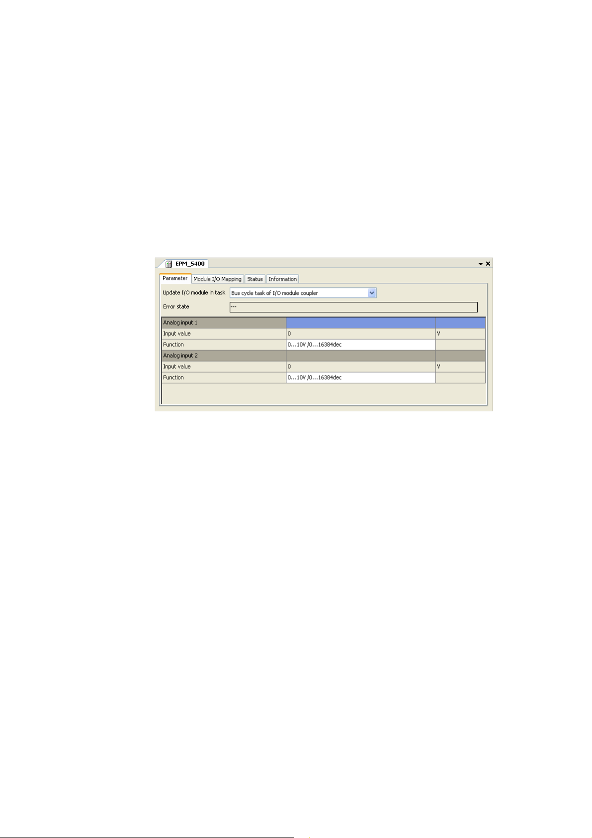
5.1 Parameterising I/O modules at the backplane bus of the L-force Controller
If you double-click an I/O compound module in the Device view of the PLC Designer, the settings and
properties of the I/O compound module are displayed in the Editor view.
•The Parameter tab serves to make the settings desired for the selected I/O compound module
(for this example, an "EPM-S400" has been selected):
Lenze · I/O system 1000 · commissioning guidelines for the PLC Designer · DMS 1.2 EN · 11/2012 · TD05 35
Page 36
5 Parameterising I/O modules in the »PLC Designer«
5.2 Parameterising I/O modules on the EtherCAT bus coupler module
_ _ _ _ _ _ _ _ _ _ _ _ _ _ _ _ _ _ _ _ _ _ _ _ _ _ _ _ _ _ _ _ _ _ _ _ _ _ _ _ _ _ _ _ _ _ _ _ _ _ _ _ _ _ _ _ _ _ _ _ _ _ _ _
5.2 Parameterising I/O modules on the EtherCAT bus coupler module
If you double-click the EtherCAT bus coupler module (EPM-S130) in the Device view of the PLC
Designer, the settings and properties of the bus coupler module are displayed in the Editor view.
•The All parameters tab displays the parameters of the bus coupler module and all attached I/O
compound modules in a hierarchical structure.
• The following example displays the setting parameters of an "EPM-S400":
Optionally, you can display the settings and properties of an individual I/O compound module by
double-clicking the corresponding one in the Device view.
•The Modules tab serves to make the settings desired for the selected I/O compound module (for
this example, an "EPM-S400" has been selected):
36
Lenze · I/O system 1000 · commissioning guidelines for the PLC Designer · DMS 1.2 EN · 11/2012 · TD05
Page 37
5 Parameterising I/O modules in the »PLC Designer«
5.3 Parameterising I/O modules on the CANopen bus coupler module
_ _ _ _ _ _ _ _ _ _ _ _ _ _ _ _ _ _ _ _ _ _ _ _ _ _ _ _ _ _ _ _ _ _ _ _ _ _ _ _ _ _ _ _ _ _ _ _ _ _ _ _ _ _ _ _ _ _ _ _ _ _ _ _
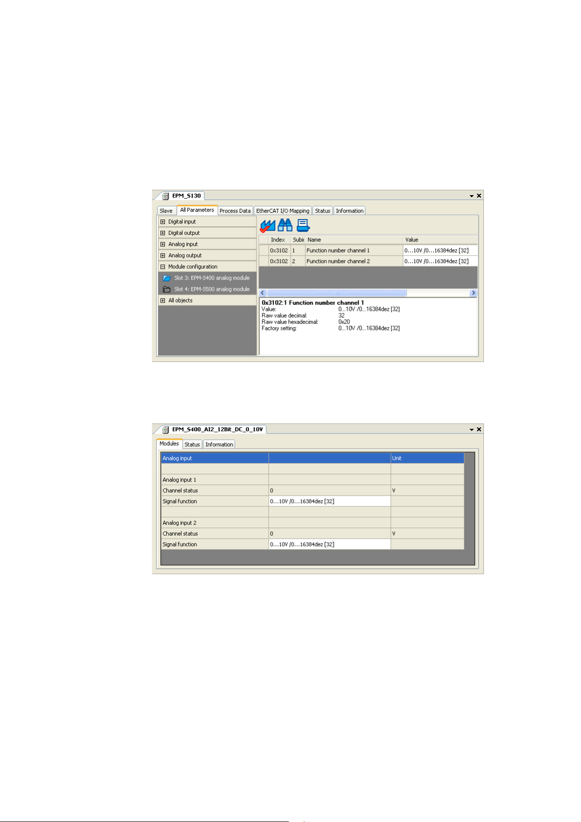
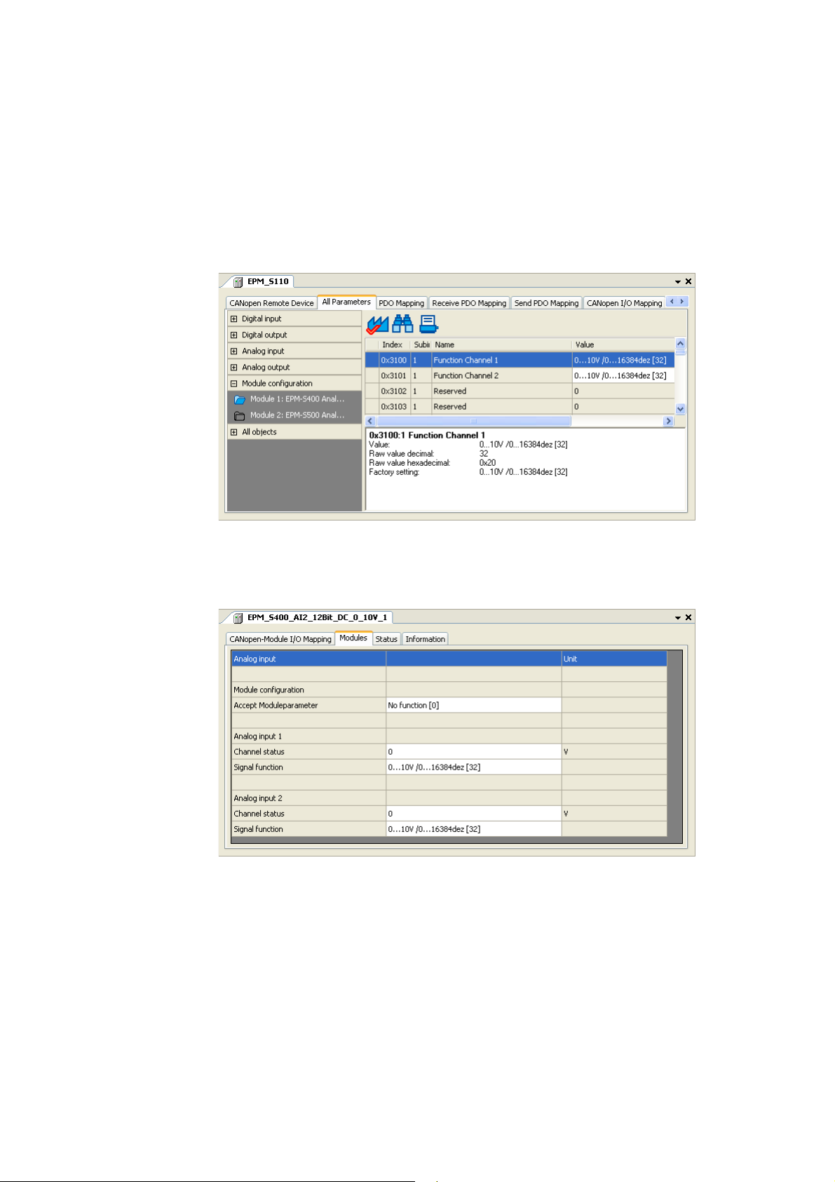
5.3 Parameterising I/O modules on the CANopen bus coupler module
If you double-click the CANopen bus coupler module (EPM-S110) in the Device view of the PLC
Designer, the settings and properties of the bus coupler module are displayed in the Editor view.
•The All parameters tab displays the parameters of the bus coupler module and all attached I/O
compound modules in a hierarchical structure.
• The following example displays the setting parameters of an "EPM-S400":
Optionally, you can display the settings and properties of an individual I/O compound module by
double-clicking the corresponding one in the Device view.
•The Modules tab serves to make the settings desired for the selected I/O compound module (for
this example, an "EPM-S400" has been selected):
Lenze · I/O system 1000 · commissioning guidelines for the PLC Designer · DMS 1.2 EN · 11/2012 · TD05 37
Page 38

5 Parameterising I/O modules in the »PLC Designer«
5.3 Parameterising I/O modules on the CANopen bus coupler module
_ _ _ _ _ _ _ _ _ _ _ _ _ _ _ _ _ _ _ _ _ _ _ _ _ _ _ _ _ _ _ _ _ _ _ _ _ _ _ _ _ _ _ _ _ _ _ _ _ _ _ _ _ _ _ _ _ _ _ _ _ _ _ _
Acceptance of parameter changes:
In order that parameter changes are accepted in case of parameterisable I/O compound modules,
they have to be confirmed as follows:
A. On the All parameters tab of the bus coupler module:
Set the 0x31FF index to "Accept moduleparameter [255]" in the All objects tab.
B. On the Modules of the I/O compound module:
Select ""Accept Moduleparameter [255]" in the Accept Moduleparameter line.
38
Lenze · I/O system 1000 · commissioning guidelines for the PLC Designer · DMS 1.2 EN · 11/2012 · TD05
Page 39

6 Error messages (backplane bus)
_ _ _ _ _ _ _ _ _ _ _ _ _ _ _ _ _ _ _ _ _ _ _ _ _ _ _ _ _ _ _ _ _ _ _ _ _ _ _ _ _ _ _ _ _ _ _ _ _ _ _ _ _ _ _ _ _ _ _ _ _ _ _ _
6 Error messages (backplane bus)
The diagnostics tab of the "I_O_Modul_Koppler" displays the total error status of the I/O system
and the current error status of the available I/O compound modules.
• In the following example, the represented station structure in the device view is faulty and thus
the I/O compound module EPM-S503 at the backplane bus is not available:
Short overview of the possible error messages
Error number Error text Remedy
11 Too many I/O modules for the task cycle time selected Increase cycle time
12 FIFO response full Contact Lenze
32 Timeout reset Contact Lenze
33 Timeout reset error Contact Lenze
96 Too many I/O modules for the task cycle time selected Increase cycle time
97 Too many I/O modules for the task cycle time selected Increase cycle time
98 Too many I/O modules for the task cycle time selected Increase cycle time
99 Too many I/O modules for the task cycle time selected Increase cycle time
100 Too many I/O modules for the task cycle time selected Increase cycle time
101 Timeout for master queue operation Contact Lenze
102 Bus initialisation error with one I/O module Contact Lenze
103 Master queue operation error
Not all I/O modules can be reached
104 Read semaphore timeout for group 1
105 Read semaphore timeout for group 2
106 Read semaphore timeout for group 3
107 Write semaphore timeout for group 1
108 Write semaphore timeout for group 2
109 Write semaphore timeout for group 3
110 Internal backplane bus hardware error Contact Lenze
116 Read semaphore timeout for group 1
117 Read semaphore timeout for group 2
118 Read semaphore timeout for group 3
119 Write semaphore timeout for group 1
120 Write semaphore timeout for group 2
121 Write semaphore timeout for group 3
136 Configuration error in the topology of the I/O modules Check sequence of the I/O
Contact Lenze
modules in the device view.
Lenze · I/O system 1000 · commissioning guidelines for the PLC Designer · DMS 1.2 EN · 11/2012 · TD05 39
Page 40

6 Error messages (backplane bus)
_ _ _ _ _ _ _ _ _ _ _ _ _ _ _ _ _ _ _ _ _ _ _ _ _ _ _ _ _ _ _ _ _ _ _ _ _ _ _ _ _ _ _ _ _ _ _ _ _ _ _ _ _ _ _ _ _ _ _ _ _ _ _ _
Error number Error text Remedy
137 Too many tasks for the processing of I/O modules Reduce the number of tasks.
138 Device description does not contain a device type Contact Lenze
139 Error while writing the initialisation parameters Contact Lenze
140 No definition for number of channels in device description Contact Lenze
181 Synchronisation of the I/O system incorrect Contact Lenze
200 SDO timeout Contact Lenze
220 SDO communication error Contact Lenze
221 Physical I/O module topology could not be read. Contact Lenze
222 I/O system driver could not be opened. Contact Lenze
Three tasks are maximally
possible.
40 Lenze · I/O system 1000 · commissioning guidelines for the PLC Designer · DMS 1.2 EN · 11/2012 · TD05
Page 41

Index
Index
_ _ _ _ _ _ _ _ _ _ _ _ _ _ _ _ _ _ _ _ _ _ _ _ _ _ _ _ _ _ _ _ _ _ _ _ _ _ _ _ _ _ _ _ _ _ _ _ _ _ _ _ _ _ _ _ _ _ _ _ _ _ _ _
A
Application notes 6
C
Configuring, station structure 14
Conventions used 4
D
Device architecture, I/O system 1000 9
Document history 3
E
E-mail to Lenze 42
Establishing communication with the L-force Controller 12
F
Feedback to Lenze 42
M
Mapping the station structure in the PLC Designer 14
N
New project, creating 14
P
Parameter settings, I/O system 1000 35
Project, creating 14
Properties, I/O system 1000 8
S
Safety instructions 6
Structure of safety instructions 6
Structure of the safety instructions 6
T
Target group 3
Terminology used 5
V
Validity, information regarding 3
Lenze · I/O-System 1000 · Inbetriebnahme-Leitfaden für den PLC Designer · DMS 1.2 EN · 11/2012 · TD05 41
Page 42

Your opinion is important to us
)(('%$&.
We have created these instructions to the best of our knowledge
with the objective of providing you with the best possible support
when handling our product.
Perhaps we did not succeed in every aspect. If you have suggestions
for improvement, please e-mail us to:
feedback-docu@Lenze.de
Thank you very much for your support.
Your Lenze documentation team
42
Page 43

43
Page 44

I/O system 1000 · commissioning guidelines for the PLC Designer · EDSPMIO1000 · 13395451 · DMS 1.2 EN · 11/2012 · TD05
Lenze Automation GmbH
Hans-Lenze-Str. 1
D-31855 Aerzen
Germany
+49 (0)51 54 / 82-0
+49 (0)51 54 / 82-28 00
Lenze@Lenze.de
www.Lenze.com
Service
Lenze Service GmbH
Breslauer Straße 3
D-32699 Extertal
Germany
00 80 00 / 24 4 68 77 (24 h helpline)
+49 (0)51 54 / 82-11 12
Service@Lenze.de
L
 Loading...