

Page 1

EDSPLCLIB01
13384444
Ä.GMMä
L-force Controls
Software Manual
Function library "LenzeIO1000Drv"
for Lenze software »Drive PLC Developer Studio« and »PLC Designer«
L
Page 2

Function library "LenzeIo1000Drv"
Contents
Contents
1 About this documentation . . . . . . . . . . . . . . . . . . . . . . . . . . . . . . . . . . . . . . . . . . . . . . . . . . . . . . . . . 3
1.1 Conventions used
1.2 Definition of notes used
2 System requirements
3 Project planning concept
3.1 Parameterisation and process data blocks
3.2 Initialisation of the CAN driver
3.3 Minimum configuration
4 Function blocks
4.1 L_io1000ParAiDc - Parameterise analog inputs
4.2 L_io1000ParAiTemperature - Parameterise temperature measurement
4.3 L_io1000ParAoDc - Parameterise analog outputs
4.4 L_io1000ParCounterEPMS600 - Parameterise counter
4.5 L_io1000ParCounterEPMS601 - Parameterise counter
4.6 L_io1000ParCounterEPMS602 - Parameterise counter
4.7 L_io1000ParCounterEPMS603 - Parameterise counter
. . . . . . . . . . . . . . . . . . . . . . . . . . . . . . . . . . . . . . . . . . . . . . . . . . . . . . . . . . . . . . . . . . . 11
. . . . . . . . . . . . . . . . . . . . . . . . . . . . . . . . . . . . . . . . . . . . . . . . . . . . . . . . . . . . . . . 4
. . . . . . . . . . . . . . . . . . . . . . . . . . . . . . . . . . . . . . . . . . . . . . . . . . . . . . . . . 5
. . . . . . . . . . . . . . . . . . . . . . . . . . . . . . . . . . . . . . . . . . . . . . . . . . . . . . . . . . . . . . 6
. . . . . . . . . . . . . . . . . . . . . . . . . . . . . . . . . . . . . . . . . . . . . . . . . . . . . . . . . . . 8
. . . . . . . . . . . . . . . . . . . . . . . . . . . . . . . . . . . . . . . . 8
. . . . . . . . . . . . . . . . . . . . . . . . . . . . . . . . . . . . . . . . . . . . . . . . . . . 9
. . . . . . . . . . . . . . . . . . . . . . . . . . . . . . . . . . . . . . . . . . . . . . . . . . . . . . . . . 10
. . . . . . . . . . . . . . . . . . . . . . . . . . . . . . . . . . . 12
. . . . . . . . . . . . 14
. . . . . . . . . . . . . . . . . . . . . . . . . . . . . . . . . 17
. . . . . . . . . . . . . . . . . . . . . . . . . . . . . 19
. . . . . . . . . . . . . . . . . . . . . . . . . . . . . 23
. . . . . . . . . . . . . . . . . . . . . . . . . . . . . 28
. . . . . . . . . . . . . . . . . . . . . . . . . . . . . 32
4.8 L_io1000ParCounterEPMS604 - Parameterise encoder evaluation
4.9 L_io1000ParRestore - Load default setting in I/O system
4.10 L_io1000ParPDO15 - Communication settings PDO1 ... PDO5
4.11 L_io1000ParPDO610 - Communication settings PDO6 ... PDO10
4.12 L_io1000ParComGuarding - Parameterising monitoring functions
4.13 L_io1000Data15 - Process data transfer PDO1 ... PDO5
4.14 L_io1000Data610 - process data transfer PDO6 ... PDO10
5 Index
. . . . . . . . . . . . . . . . . . . . . . . . . . . . . . . . . . . . . . . . . . . . . . . . . . . . . . . . . . . . . . . . . . . . . . . . . . . . 61
Your opinion is important to us
. . . . . . . . . . . . . . . . . . . . . . . . . . . . . . . . . . . . . . . . . . . . . . . . . . . . . . . . 62
. . . . . . . . . . . . . . . . . . 35
. . . . . . . . . . . . . . . . . . . . . . . . . . 38
. . . . . . . . . . . . . . . . . . . . . . 40
. . . . . . . . . . . . . . . . . . . 46
. . . . . . . . . . . . . . . . . 52
. . . . . . . . . . . . . . . . . . . . . . . . . . . . 55
. . . . . . . . . . . . . . . . . . . . . . . . . . 58
2 L DMS 1.0 EN - 07/2011 - TD05
Page 3

1 About this documentation
This documentation describes the function blocks that are contained in the
"LenzeIo1000Drv" function library. These function blocks enable the access of Lenze PLC
products (e.g. 9400
ServoPLC) to the decentralised I/O system 1000.
Note!
The "LenzeIo1000Drv" is exclusively suitable for Lenze-PLCs the project planning
environment of which is not
Functional survey
Loading of the default setting of the L-force I/O system 1000
Parameter setting of the I/O compound modules (analog inputs and outputs,
temperature measurement, counters, encoder evaluation, pulse width modulation)
Function library "LenzeIo1000Drv"
About this documentation
provided with an *.eds import!
Setting of the communication-relevant parameters in the I/O system
Coordination of the process communication between PLC and I/O system
Validity information
The information given in this documentation is valid for the following function library:
Function library From version
LenzeIo1000DrvVxx.lib V1.0
Document history
Version Description
1.0 07/2011 TD05 First edition for LenzeIo1000DrvV10.lib
Tip!
The "LenzeIo1000DrvVxx.lib" library version can be queried via the following global
constants:
• C_wLenzeIo1000DrvVersionER: Enabled major version
• C_wLenzeIo1000DrvVersionEL: Enabled minor version
• C_wLenzeIo1000DrvVersionIR: Internal minor version
• C_wLenzeIo1000DrvVersionBN: Internal build number
DMS 1.0 EN - 07/2011 - TD05 L 3
Page 4
Function library "LenzeIo1000Drv"
About this documentation
Conventions used
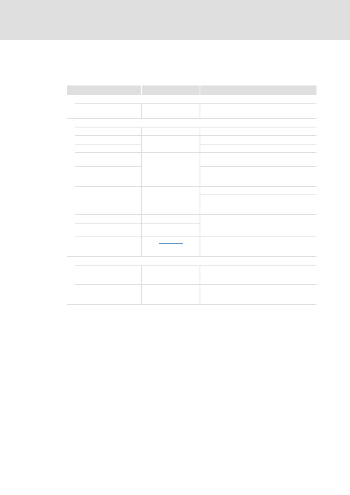
1.1 Conventions used
This documentation uses the following conventions to distinguish between different types
of information:
Type of information Writing Examples/notes
Numbers
Decimal separator Point The decimal point is always used.
Text
Program name » « The Lenze PC software »PLC Designer«...
Window Italics The Message window ... / The Options dialog box...
Variable identifier By setting bEnable to TRUE...
Control element Bold The OK button... / The copy command... / The
Sequence of menu
commands
Shortcut <Bold> Press <F1> to open the online help.
Program code Courier
Keyword Courier bold
Example: 1234.56
Properties tab... / The Name input field...
If several commands must be used in sequence to
carry out a function, then the individual commands
are separated by an arrow: Select File
If a key combination is required for a command, a "+"
is inserted between the key identifiers: Use
<Shift>+<ESC>...
IF var1 < var2 THEN
a = a + 1
END IF
Open to...
Hyperlink Underlined
Symbols
Page reference ( 4) Optically highlighted reference to another page. It is
Step-by-step instructions
Optically highlighted reference to another topic. It is
activated with a mouse click in this online
documentation.
activated with a mouse click in this online
documentation.
Step-by-step instructions are indicated by a
pictograph.
4 L DMS 1.0 EN - 07/2011 - TD05
Page 5

1.2 Definition of notes used
The following signal words and symbols are used in this documentation to indicate
dangers and important information:
Safety instructions
Layout of the safety instructions:
Danger!
(characterises the type and severity of danger)
Note
(describes the danger and gives information about how to prevent dangerous
situations)
Function library "LenzeIo1000Drv"
About this documentation
Definition of notes used
Pictograph Signal word Meaning
Danger! Danger of personal injury through dangerous electrical voltage
Danger! Danger of personal injury through a general source of danger
Stop! Danger of property damage
Application notes
Pictograph Signal word Meaning
Note! Important note to ensure trouble-free operation
Reference to an imminent danger that may result in death or serious personal
injury if the corresponding measures are not taken.
Reference to an imminent danger that may result in death or serious personal
injury if the corresponding measures are not taken.
Reference to a possible danger that may result in property damage if the
corresponding measures are not taken.
Tip! Useful tip for simple handling
Reference to another document
DMS 1.0 EN - 07/2011 - TD05 L 5
Page 6

Function library "LenzeIo1000Drv"
System requirements
2 System requirements
Software
The function library can be used with the following Lenze software:
Product Type designation Version
Drive PLC Developer Studio ESP-DDS2-x 2.x
PLC Designer V2 2.2 or higher
PLC Designer V3 ESPEVPDxxxxxx 3.x
Supported target systems
Product range Type designation Hardware version From software version
Drive PLC EPL-10200 1A or higher 2.x
9300 Servo PLC EVS93xx-EI
EVS93xx-ET
ECS ECSxA 1B or higher 7.x
9400 ServoPLC E94AxPExxxx 2A or higher 2.x
2M or higher 2.x
Required libraries for use in »Drive PLC Developer Studio«
with Drive PLC/9300 Servo PLC/ECS:
Unless already available, insert the following libraries into the library management (menu
WindowLibrary management):
CANopenSdoDrvV10.lib
LenzeTICan9300V10.lib
LenzeIo1000DrvV10.lib
LenzeConversionBoxV10.lib (optional)
Note!
Before the "LenzeTICan9300V10.lib" library is inserted into the library manager,
the CAN_Management system block must be implemented into the Control
configuration.
If the CAN_Management system block is missing or implemented subsequently,
a compilation error may be caused during the project compilation.
Remedy:
implement the CAN_Management system block and re-insert the library into
the library manager.
Remove "LenzeTICan9300V10.lib" library from the library manager,
6 L DMS 1.0 EN - 07/2011 - TD05
Page 7

Function library "LenzeIo1000Drv"
System requirements
Required libraries for use in the »PLC Designer« with 9400 ServoPLC:
Unless already available, insert the following libraries into the library management (menu
WindowLibrary management):
LenzeCanOpenSdoDrvV10.lib
LenzeTICan9400V10.lib
LenzeIo1000DrvV10.lib
LenzeConversionBoxV10.lib (optional)
DMS 1.0 EN - 07/2011 - TD05 L 7
Page 8

Function library "LenzeIo1000Drv"
Project planning concept
Parameterisation and process data blocks
3 Project planning concept
The user is provided with suitable function blocks by the "LenzeIo1000Drvlib" library to
enable support of the decentralised I/O system through Lenze PLC products These function
blocks are implemented in an IEC 61131 program and serve both for parameterising the I/
O system and for process data processing. They provide digital and analog input and
output information of the I/O system. Configurations of the user via user codes are not
required.
3.1 Parameterisation and process data blocks
The "LenzeIo1000Drvlib" library contains two types of function blocks:
1. Parameterisation blocks
2. Process data blocks
Parameterisation blocks
Parameterisation blocks allow the modification of index information in the decentralised
I/O system and the transmission of specified data. These data are transmitted only once to
the I/O system during the initialisation phase..
The parameterisation blocks for modules and monitoring functions are required for
individual parameter setting of analog modules, communication monitoring, etc.
The parameterisation blocks communication settings (L_io1000ParPDO15
L_io1000ParPDO610
) are mandatory for data exchange between PLC and I/O system.
and
Note!
In case of parameterisation blocks with the same bus node address at the
byNodeAdr input, the bExecute inputs must not be set to TRUE at the same time.
The parameter setting of the modules and the communication settings of a bus
coupler have to be started successively.
Process data blocks
Process data blocks are required for transmitting and receiving I/O data between PLC and
I/O system. The process data blocks L_io1000Data15
evaluate and process the current process data information of the inputs of the I/O system
in the PLC program. Information and data of the PLC control can be transmitted to the
process via the output modules of the I/O system.
and L_io1000Data610 serve to
8 L DMS 1.0 EN - 07/2011 - TD05
Page 9

3.2 Initialisation of the CAN driver
The "LenzeIo1000Drv.lib" function library for the L-force I/O system 1000 is based on a
library for transmitting and receiving CAN objects. Depending on the PLC version, the "CAN
on board" or an optional fieldbus card can be used as communication channel.
9400 ServoPLC
For using the "LenzeCanMsg.lib" library, an initialisation of the CAN driver with L_CanInit
function block call is required. This function block must only be called once. Thus, best use
the "PLC_START" system event for calling this function.
The L_CanInit function block outputs information on the communication channel used via
its dwHandle output. This information must be provided to the blocks of the
"LenzeIo1000Drv.Lib" via the dwHandle input.
Drive PLC, 9300 Servo PLC, ECS
For using the "LenzeCanDrv.lib" library, an initialisation of the CAN driver with the
L_CanInit function call is required. This function must only be called once. Thus, best use
the system POU "PLC_ColdStart" for calling this function.
Function library "LenzeIo1000Drv"
Project planning concept
Initialisation of the CAN driver
The L_CanInit function returns information on the communication channel used via the
dwHandle variable. This information must be provided to the blocks of the
"LenzeIo1000Drv.Lib" via the dwHandle input.
DMS 1.0 EN - 07/2011 - TD05 L 9
Page 10
Function library "LenzeIo1000Drv"
Project planning concept
Minimum configuration
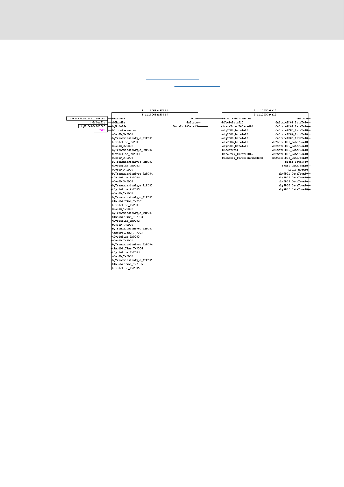
3.3 Minimum configuration
For implementing the I/O system, a minimum configuration must be carried out. It consists
of a parameterisation block L_io1000ParPDO15
relationships and a process data block L_io1000Data15
information.
The parameterisation block must be connected to the process data block as follows:
for parameterising the communication
for evaluation the input/output
The parameterisation block does not have to be executed in the same task as the
process data block. In this case, the outputs of the parameterisation block must be
connected to the inputs of the process data block.
10 L DMS 1.0 EN - 07/2011 - TD05
Page 11
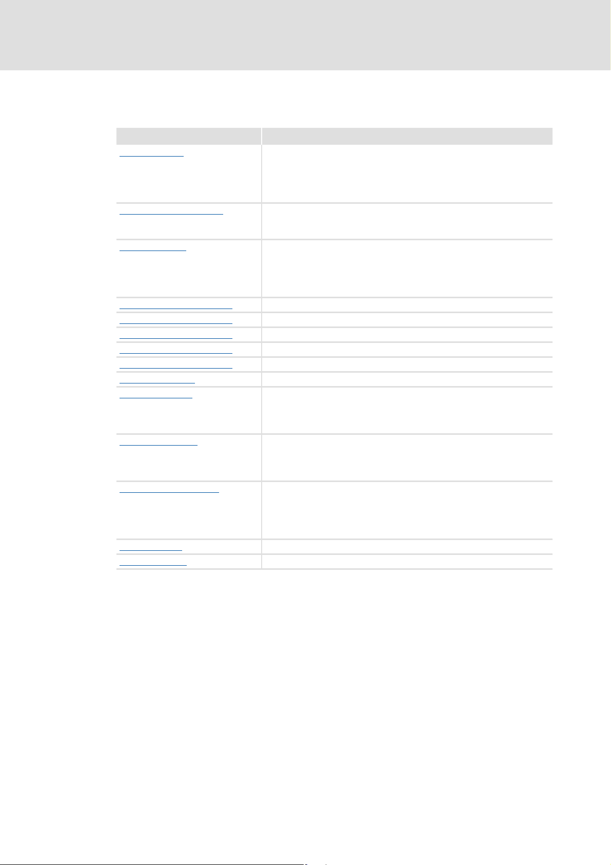
4 Function blocks
Function block Function
L_io1000ParAiDc
L_io1000ParAiTemperature
L_io1000ParAoDc
L_io1000ParCounterEPMS600
L_io1000ParCounterEPMS601
L_io1000ParCounterEPMS602
L_io1000ParCounterEPMS603
L_io1000ParCounterEPMS604
L_io1000ParRestore
L_io1000ParPDO15
L_io1000ParPDO610
L_io1000ParComGuarding
L_io1000Data15
L_io1000Data610 Process data transfer PDO6 ... PDO10
Function library "LenzeIo1000Drv"
Function blocks
Parameterise I/O compound modules "analog inputs":
• EPM-S400
• EPM-S401
• EPM-S402
• EPM-S403
Parameterise I/O compound modules "temperature measurement":
• EPM-S404
• EPM-S405
Parameterise I/O compound modules "Analog outputs":
• EPM-S500
• EPM-S501
• EPM-S502
• EPM-S503
Parameterise I/O compound modules EPM-S600 (counter)
Parameterise I/O compound modules EPM-S601 (counter)
Parameterise I/O compound modules EPM-S602 (counter)
Parameterise I/O compound modules EPM-S603 (counter)
Parameterise I/O compound module EPM-S604 (encoder evaluation)
Load default setting in I/O system
Communication settings PDO1 ... PDO5:
• Identifier
• Transmission mode
• Cycle time/blocking time
Communication settings PDO6 ... PDO10:
• Identifier
• Transmission mode
• Cycle time/blocking time
Parameterise monitoring functions:
•NodeGuarding
•Heartbeat
• Switching performance of the output channels in the event of an error
• Timeout monitoring
Process data transfer PDO1 ... PDO5
DMS 1.0 EN - 07/2011 - TD05 L 11
Page 12

Function library "LenzeIo1000Drv"
Function blocks
L_io1000ParAiDc - Parameterise analog inputs
4.1 L_io1000ParAiDc - Parameterise analog inputs
Call possible in: ; Cyclic task
Interrupt task
; Time-controlled task (INTERVAL)
Event-controlled task (EVENT)
This FB serves to parameterise the analog input modules EPM-S400, EPM-S401, EPM-S402
and EPM-S403.
A FALSE/TRUE edge at the bExecute input starts the parameter setting.
The dnState output shows the transmission status.
L_io1000ParAiDc
⎯ bExecute bDone ⎯
⎯ dwHandle dnState ⎯
⎯ byNodeAdr
⎯ byAnalogModuleNo
⎯ byNoOfChannels
⎯ byFunction_CH1
⎯ byFunction_CH2
⎯ byFunction_CH3
⎯ byFunction_CH4
Inputs
Identifier/data type Information/possible settings
bExecute
dwHandle
DWORD
byNodeAdr
byAnalogModuleNo
byNoOfChannels
byFunction_CH1 ... _CH4
FALSEÊTRUE Start parameter setting of the analog input module
BOOL
• 9400 ServoPLC: Handle created by FB L_CanInit
• Drive PLC, 9300 Servo PLC, ECS: 10
1 ... 127 CAN node address of the I/O system
BYTE
1 ... 64 Number of the analog input module
BYTE
Number of channels of the I/O system
BYTE
Function channel 1 ... 4
BYTE
• see system manual "I/O system 1000":
EPM-S400: Chapter 7.8.1
EPM-S401: Chapter 7.8.2
EPM-S402: Chapter 7.8.3
EPM-S403: Chapter 7.8.4
2 EPM-S400, EPM-S402
4 EPM-S401, EPM-S403
12 L DMS 1.0 EN - 07/2011 - TD05
Page 13

Outputs
Identifier/data type Value/meaning
bDone
dnState
BOOL
Status of parameter setting
DINT
• When the function has been executed successfully, the value "0" is output.
TRUE Parameter setting completed successfully
-1003 byNodeAdr input is not in valid range
-1004 Wrong value at byAnalogModuleNo input
-1005 Wrong value at byNoOfChannels input
-2000 Error while executing the internal block for writing CAN indices
-2002 Wrong value at the dwHandle input
-2003 Wrong value at the byNodeAdr input
-2006 Writing of a wrong CAN index
-2007 Timeout while writing a CAN index of the I/O system
-2100 Error while writing a parameter of the I/O system
-2101 Output buffer is full
Function library "LenzeIo1000Drv"
Function blocks
L_io1000ParAiDc - Parameterise analog inputs
1 Parameter setting started
0 Parameter setting completed successfully
DMS 1.0 EN - 07/2011 - TD05 L 13
Page 14

Function library "LenzeIo1000Drv"
Function blocks
L_io1000ParAiTemperature - Parameterise temperature measurement
4.2 L_io1000ParAiTemperature - Parameterise temperature measurement
Call possible in: ; Cyclic task
Interrupt task
; Time-controlled task (INTERVAL)
Event-controlled task (EVENT)
This FB serves to parameterise the analog input modules EPM-S404 and EPM-S405.
A FALSE/TRUE edge at the bExecute input starts the parameter setting.
The dnState output shows the transmission status.
L_io1000ParAiTemperature
⎯ bExecute bDone ⎯
⎯ dwHandle dnState ⎯
⎯ byNodeAdr
⎯ byAnalogModuleNo
⎯ byNoOfChannels
⎯ bDiagnosticAlarm
⎯ byTemperatureSystem
⎯ byFilter
⎯ bWireBreakDetection_CH1
⎯ byFunction_CH1
⎯ bySampling_CH1
⎯ bLimitAlarm_CH1
⎯ nUpperLimit_CH1
⎯ nLowerLimit_CH1
⎯ bWireBreakDetection_CH2
⎯ byFunction_CH2
⎯ bySampling_CH2
⎯ bLimitAlarm_CH2
⎯ nUpperLimit_CH2
⎯ nLowerLimit_CH2
⎯ bWireBreakDetection_CH3
⎯ byFunction_CH3
⎯ bySampling_CH3
⎯ bLimitAlarm_CH3
⎯ nUpperLimit_CH3
⎯ nLowerLimit_CH3
⎯ bWireBreakDetection_CH4
⎯ byFunction_CH4
⎯ bySampling_CH4
⎯ bLimitAlarm_CH4
⎯ nUpperLimit_CH4
⎯ nLowerLimit_CH4
14 L DMS 1.0 EN - 07/2011 - TD05
Page 15

L_io1000ParAiTemperature - Parameterise temperature measurement
Inputs
Identifier/data type Information/possible settings
bExecute
dwHandle
DWORD
byNodeAdr
byAnalogModuleNo
byNoOfChannels
bDiagnosticAlarm
byTemperatureSystem
byFilter
bWireBreakDetection
_CH1 ... _CH4
byFunction_CH1 ... _CH4
bySampling_CH1 ... _CH4
bLimitAlarm_CH1 ... _CH4
nUpperLimit_CH1 ... _CH4
nLowerLimit_CH1 ... _CH4
FALSEÊTRUE Start parameter setting of the analog input module
BOOL
• 9400 ServoPLC: Handle created by FB L_CanInit
• Drive PLC, 9300 Servo PLC, ECS: 10
1 ... 127 CAN node address of the I/O system
BYTE
1 ... 64 Number of the analog input module
BYTE
Number of channels of the I/O system
BYTE
BOOL
Temperature system
BYTE
Activate interference frequency suppression
BYTE
BOOL
Function channel 1 ... 4
BYTE
• see system manual "I/O system 1000":
EPM-S404: Chapter 7.9.1
EPM-S405: Chapter 7.9.2
Conversion time channel 1 ... 4
BYTE
• see system manual "I/O system 1000":
EPM-S404: Chapter 7.9.1
EPM-S405: Chapter 7.9.2
BOOL
Upper limit value channel 1 ... 4
BYTE
Lower limit value channel 1 ... 4
BYTE
2 EPM-S405
4 EPM-S404
TRUE Enable diagnostic alarm
0°C
1°F
2K
160Hz
250Hz
TRUE Activate open circuit detection channel 1 ... 4
TRUE Activate limit value monitoring channel 1 ... 4
Function library "LenzeIo1000Drv"
Function blocks
DMS 1.0 EN - 07/2011 - TD05 L 15
Page 16

Function library "LenzeIo1000Drv"
Function blocks
L_io1000ParAiTemperature - Parameterise temperature measurement
Outputs
Identifier/data type Value/meaning
bDone
dnState
BOOL
Status of parameter setting
DINT
• When the function has been executed successfully, the value "0" is output.
TRUE Parameter setting completed successfully
1 Parameter setting started
0 Parameter setting completed successfully
-1003 byNodeAdr input is not in valid range
-1004 Wrong value at byAnalogModuleNo input
-1005 Wrong value at byNoOfChannels input
-1007 Wrong value at byTemperatureSystem input
-1009 Wrong value at byFilter input
-2000 Error while executing the internal block for writing CAN indices
-2002 Wrong value at the dwHandle input
-2003 Wrong value at the byNodeAdr input
-2006 Writing of a wrong CAN index
-2007 Timeout while writing a CAN index of the I/O system
-2100 Error while writing a parameter of the I/O system
-2101 Output buffer is full
16 L DMS 1.0 EN - 07/2011 - TD05
Page 17

Function library "LenzeIo1000Drv"
L_io1000ParAoDc - Parameterise analog outputs
4.3 L_io1000ParAoDc - Parameterise analog outputs
Function blocks
Call possible in: ; Cyclic task
Interrupt task
; Time-controlled task (INTERVAL)
Event-controlled task (EVENT)
This FB serves to parameterise the analog output modules EPM-S500, EPM-S501, EPMS502 and EPM-S503.
A FALSE/TRUE edge at the bExecute input starts the parameter setting.
The dnState output shows the transmission status.
L_io1000ParAoDc
⎯ bExecute bDone ⎯
⎯ dwHandle dnState ⎯
⎯ byNodeAdr
⎯ byAnalogModuleNo
⎯ byNoOfChannels
⎯ bShortCircuitDetection_CH1
⎯ byFunction_CH1
⎯ bShortCircuitDetection_CH2
⎯ byFunction_CH2
⎯ bShortCircuitDetection_CH3
⎯ byFunction_CH3
⎯ bShortCircuitDetection_CH4
⎯ byFunction_CH4
Inputs
Identifier/data type Information/possible settings
bExecute
dwHandle
DWORD
byNodeAdr
byAnalogModuleNo
byNoOfChannels
bShortCircuitDetection
_CH1 ... _CH4
byFunction_CH1 ... _CH4
FALSEÊTRUE Start parameter setting of the analog output module
BOOL
• 9400 ServoPLC: Handle created by FB L_CanInit
• Drive PLC, 9300 Servo PLC, ECS: 10
1 ... 127 CAN node address of the I/O system
BYTE
1 ... 64 Number of the analog output module
BYTE
Number of channels of the I/O system
BYTE
BOOL
Function channel 1 ... 4
BYTE
• see system manual "I/O system 1000":
EPM-S500: Chapter 7.8.5
EPM-S501: Chapter 7.8.6
EPM-S502: Chapter 7.8.7
EPM-S503: Chapter 7.8.8
2 EPM-S500, EPM-S502
4 EPM-S501, EPM-S503
TRUE Activate short circuit detection channel 1 ... 4
DMS 1.0 EN - 07/2011 - TD05 L 17
Page 18

Function library "LenzeIo1000Drv"
Function blocks
L_io1000ParAoDc - Parameterise analog outputs
Outputs
Identifier/data type Value/meaning
bDone
dnState
BOOL
Status of parameter setting
DINT
• When the function has been executed successfully, the value "0" is output.
TRUE Parameter setting completed successfully
1 Parameter setting started
0 Parameter setting completed successfully
-1003 byNodeAdr input is not in valid range
-1004 Wrong value at byAnalogModuleNo input
-1005 Wrong value at byNoOfChannels input
-2000 Error while executing the internal block for writing CAN indices
-2002 Wrong value at the dwHandle input
-2003 Wrong value at the byNodeAdr input
-2006 Writing of a wrong CAN index
-2007 Timeout while writing a CAN index of the I/O system
-2100 Error while writing a parameter of the I/O system
-2101 Output buffer is full
18 L DMS 1.0 EN - 07/2011 - TD05
Page 19

Function library "LenzeIo1000Drv"
L_io1000ParCounterEPMS600 - Parameterise counter
4.4 L_io1000ParCounterEPMS600 - Parameterise counter
Function blocks
Call possible in: ; Cyclic task
Interrupt task
; Time-controlled task (INTERVAL)
Event-controlled task (EVENT)
This FB serves to parameterise the EPM-S600 counter module.
A FALSE/TRUE edge at the bExecute input starts the parameter setting.
The dnState output shows the transmission status.
L_io1000ParCounterEPMS600
⎯ bExecute bDone ⎯
⎯ dwHandle dnState ⎯
⎯ byNodeAdr
⎯ byAnalogModuleNo
⎯ bDiagnosticAlarm
⎯ byInputFrequencyTrackA
⎯ byInputFrequencyTrackB
⎯ byInputFrequencyLatch
⎯ byInputFrequencyGate
⎯ byInputFrequencyReset
⎯ byAlarmFunction
⎯ byCounterFunction
⎯ bySignalSelection
⎯ bActivateHardwareGate
⎯ bInternalGateInterrupt
⎯ byCompareFunction
⎯ bInvertDirectionTrackB
⎯ byResetFunction
⎯ dwLoadValue
⎯ dwEndValue
⎯ byHysteresis
⎯ byPulse
Inputs
Identifier/data type Information/possible settings
bExecute
dwHandle
DWORD
byNodeAdr
byAnalogModuleNo
bDiagnosticAlarm
DMS 1.0 EN - 07/2011 - TD05 L 19
FALSEÊTRUE Start parameter setting of the analog output module
BOOL
• 9400 ServoPLC: Handle created by FB L_CanInit
• Drive PLC, 9300 Servo PLC, ECS: 10
1 ... 127 CAN node address of the I/O system
BYTE
1 ... 64 Number of the analog output module
BYTE
TRUE Enable diagnostic alarm
BOOL
Page 20

Function library "LenzeIo1000Drv"
Function blocks
L_io1000ParCounterEPMS600 - Parameterise counter
Identifier/data type Information/possible settings
byInputFrequencyTrackA
byInputFrequencyTrackB
byInputFrequencyLatch
byInputFrequencyGate
byInputFrequencyReset
Input filter of digital input 1 "A"/"pulse"
BYTE
Input filter of digital input 5 "B"/"direction"
BYTE
Input filter of digital input 4 "latch"
BYTE
Input filter of digital input 8 "hardware gate"
BYTE
Input filter of digital input 7 "reset"
BYTE
2 100 kHz
3 60 kHz
4 30 kHz
6 10 kHz
75 kHz
82 kHz
91 kHz
2 100 kHz
3 60 kHz
4 30 kHz
6 10 kHz
75 kHz
82 kHz
91 kHz
2 100 kHz
3 60 kHz
4 30 kHz
6 10 kHz
75 kHz
82 kHz
91 kHz
2 100 kHz
3 60 kHz
4 30 kHz
6 10 kHz
75 kHz
82 kHz
91 kHz
2 100 kHz
3 60 kHz
4 30 kHz
6 10 kHz
75 kHz
82 kHz
91 kHz
20 L DMS 1.0 EN - 07/2011 - TD05
Page 21

Function library "LenzeIo1000Drv"
L_io1000ParCounterEPMS600 - Parameterise counter
Identifier/data type Information/possible settings
byAlarmFunction
byCounterFunction
bySignalSelection
bActivateHardwareGate
bInternalGateInterrupt
byCompareFunction
bInvertDirectionTrackB
byResetFunction
Process alarm
BYTE
A process alarm can be triggered in case of the following events:
bits0 Open hardware gate
bits1 Closed hardware gate
Bit 2 Counter limit overflow
bits3 Counter limit underflow
bits4 Comparison value reached
Bit 5 Final value reached
Bit 6 Latch value reached
Bit 7 Reserved
Counting function
BYTE
Signal evaluation
BYTE
Activation of hardware gate
BOOL
Gate function (internal gate)
BOOL
Comparison operation
BYTE
BOOL
Reset function
BYTE
0 Continuous counting
1 Single counting, main counting direction is forward
2 Single counting, main counting direction is backward
3 Single counting, no main counting direction
4 Periodic counting, main counting direction is forward
5 Periodic counting, main counting direction is backward
6 Periodic counting, no main counting direction
0 Counter deactivated
• The other parameter data for the counter are ignored.
1 Rotary transducer 1-fold (at A and B)
2 Rotary transducer 2-fold (at A and B)
3 Rotary transducer 4-fold (at A and B)
4 Direction (pulse at A and direction at B)
FALSE Hardware gate deactivated
• Counter starts by setting the software gate.
TRUE Hardware gate activated
• HIGH level at the gate input activates the hardware gate.
• Counter starts if hardware and software gate are set.
FALSE Cancel (counting process restarts from the load value)
TRUE Interrupt (counting process is continued with counter content)
0 Output never switches
1 Output switches if count value ≥ comparison value.
2 Output switches if count value ≤ comparison value.
3 Output switches if count value = comparison value.
TRUE Invert counting direction track B
0 Deactivated
1HIGH level
2 Rising edge
3 one-time rising edge
Function blocks
DMS 1.0 EN - 07/2011 - TD05 L 21
Page 22

Function library "LenzeIo1000Drv"
Function blocks
L_io1000ParCounterEPMS600 - Parameterise counter
Identifier/data type Information/possible settings
dwLoadValue
DWORD
dwEndValue
DWORD
byHysteresis
byPulse
Outputs
Identifier/data type Value/meaning
bDone
dnState
Load value
Final value
Hysteresis
BYTE
Pulse duration
BYTE
TRUE Parameter setting completed successfully
BOOL
Status of parameter setting
DINT
• When the function has been executed successfully, the value "0" is output.
1 Parameter setting started
0 Parameter setting completed successfully
-1003 byNodeAdr input is not in valid range
-1004 Wrong value at byAnalogModuleNo input
-1007 Wrong value at byInputFrequencyTrackA input
-1008 Wrong value at byInputFrequencyTrackB input
-1009 Wrong value at byInputFrequencyLatch input
-1010 Wrong value at byInputFrequencyGate input
-1011 Wrong value at byInputFrequencyReset input
-1012 Wrong value at byAlarmFunction input
-1013 Wrong value at byCounterFunction input
-1014 Wrong value at bySignalSelection input
-1017 Wrong value at byCompareFunction input
-1019 Wrong value at byResetFunction input
-2000 Error while executing the internal block for writing CAN indices
-2002 Wrong value at the dwHandle input
-2003 Wrong value at the byNodeAdr input
-2006 Writing of a wrong CAN index
-2007 Timeout while writing a CAN index of the I/O system
-2100 Error while writing a parameter of the I/O system
-2101 Output buffer is full
22 L DMS 1.0 EN - 07/2011 - TD05
Page 23

Function library "LenzeIo1000Drv"
L_io1000ParCounterEPMS601 - Parameterise counter
4.5 L_io1000ParCounterEPMS601 - Parameterise counter
Function blocks
Call possible in: ; Cyclic task
Interrupt task
; Time-controlled task (INTERVAL)
Event-controlled task (EVENT)
This FB serves to parameterise the EPM-S601 counter module.
A FALSE/TRUE edge at the bExecute input starts the parameter setting.
The dnState output shows the transmission status.
L_io1000ParCounterEPMS601
⎯ bExecute bDone ⎯
⎯ dwHandle dnState ⎯
⎯ byNodeAdr
⎯ byAnalogModuleNo
⎯ bDiagnosticAlarm
⎯ byCnt0InputFrequencyTrackA
⎯ byCnt0InputFrequencyTrackB
⎯ byCnt0AlarmFunction
⎯ byCnt0CounterFunction
⎯ byCnt0SignalSelection
⎯ bCnt0InternalGateInterrupt
⎯ byCnt0CompareFunction
⎯ bCnt0InvertDirectionTrackB
⎯ dwCnt0SetValue
⎯ dwCnt0LoadValue
⎯ dwCnt0EndValue
⎯ byCnt0Hysteresis
⎯ byCnt1InputFrequencyTrackA
⎯ byCnt1InputFrequencyTrackB
⎯ byCnt1AlarmFunction
⎯ byCnt1CounterFunction
⎯ byCnt1SignalSelection
⎯ bCnt1InternalGateInterrupt
⎯ byCnt1CompareFunction
⎯ bCnt1InvertDirectionTrackB
⎯ dwCnt1SetValue
⎯ dwCnt1LoadValue
⎯ dwCnt1EndValue
⎯ byCnt1Hysteresis
DMS 1.0 EN - 07/2011 - TD05 L 23
Page 24

Function library "LenzeIo1000Drv"
Function blocks
L_io1000ParCounterEPMS601 - Parameterise counter
Inputs
Identifier/data type Information/possible settings
bExecute
dwHandle
DWORD
byNodeAdr
byAnalogModuleNo
bDiagnosticAlarm
byCnt0
InputFrequencyTrackA
byCnt0
InputFrequencyTrackB
byCnt0AlarmFunction
byCnt0CounterFunction
FALSEÊTRUE Start parameter setting of the analog output module
BOOL
• 9400 ServoPLC: Handle created by FB L_CanInit
• Drive PLC, 9300 Servo PLC, ECS: 10
1 ... 127 CAN node address of the I/O system
BYTE
1 ... 64 Number of the analog output module
BYTE
TRUE Enable diagnostic alarm
BOOL
Counter 1: Input filter of digital input 1, "A1"/"pulse"
BYTE
Counter 1: Input filter of digital input 5, "B1"/"direction"
BYTE
Counter 1: Process alarm
BYTE
A process alarm can be triggered in case of the following events:
Counter 1: Counting function
BYTE
2 100 kHz
3 60 kHz
4 30 kHz
6 10 kHz
75 kHz
82 kHz
91 kHz
2 100 kHz
3 60 kHz
4 30 kHz
6 10 kHz
75 kHz
82 kHz
91 kHz
bits0 Reserved
bits1 Reserved
Bit 2 Counter limit overflow
bits3 Counter limit underflow
bits4 Comparison value reached
Bit 5 Final value reached
Bit 6 Reserved
Bit 7 Reserved
0 Continuous counting
1 Single counting, main counting direction is forward
2 Single counting, main counting direction is backward
3 Single counting, no main counting direction
4 Periodic counting, main counting direction is forward
5 Periodic counting, main counting directin is backward
6 Periodic counting, no main counting direction
24 L DMS 1.0 EN - 07/2011 - TD05
Page 25

Function library "LenzeIo1000Drv"
L_io1000ParCounterEPMS601 - Parameterise counter
Identifier/data type Information/possible settings
byCnt0SignalSelection
bCnt0InternalGateInterrupt
byCnt0CompareFunction
bCnt0InvertDirectionTrackB
dwCnt0SetValue
DWORD
dwCnt0LoadValue
DWORD
dwCnt0EndValue
DWORD
byCnt0Hysteresis
byCnt1
InputFrequencyTrackA
byCnt1
InputFrequencyTrackB
Counter 1: Signal evaluation
BYTE
Counter 1: Gate function (internal gate)
BOOL
Counter 1: Comparison operation
BYTE
BOOL
Counter 1: Set value
Counter 1: Load value
Counter 1: Final value
Counter 1: Hysteresis
BYTE
Counter 2: Input filter of digital input 4, "A2"/"pulse"
BYTE
Counter 1: Input filter of digital input 8, "B2"/"direction"
BYTE
0 Counter deactivated
• The other parameter data for the counter are ignored.
1 Rotary transducer 1-fold (at A and B)
2 Rotary transducer 2-fold (at A and B)
3 Rotary transducer 4-fold (at A and B)
4 Direction (pulse at A and direction at B)
FALSE Cancel (counting process restarts from the load value)
TRUE Interrupt (counting process is continued with counter content)
0 Comparison bit is never set
1 Comparison bit is set if count value ≥ comparison value.
2 Comparison bit is set if count value ≤ comparison value.
3 Comparison bit is set if count value = comparison value.
TRUE Counter 1: Invert counting direction track B
2 100 kHz
3 60 kHz
4 30 kHz
6 10 kHz
75 kHz
82 kHz
91 kHz
2 100 kHz
3 60 kHz
4 30 kHz
6 10 kHz
75 kHz
82 kHz
91 kHz
Function blocks
DMS 1.0 EN - 07/2011 - TD05 L 25
Page 26

Function library "LenzeIo1000Drv"
Function blocks
L_io1000ParCounterEPMS601 - Parameterise counter
Identifier/data type Information/possible settings
byCnt1AlarmFunction
byCnt1CounterFunction
byCnt1SignalSelection
bCnt1InternalGateInterrupt
byCnt1CompareFunction
bCnt1InvertDirectionTrackB
dwCnt1SetValue
DWORD
dwCnt1LoadValue
DWORD
dwCnt1EndValue
DWORD
byCnt1Hysteresis
Counter 2: Process alarm
BYTE
A process alarm can be triggered in case of the following events:
bits0 Reserved
bits1 Reserved
Bit 2 Counter limit overflow
bits3 Counter limit underflow
bits4 Comparison value reached
Bit 5 Final value reached
Bit 6 Reserved
Bit 7 Reserved
Counter 2: Counting function
BYTE
Counter 2: Signal evaluation
BYTE
Counter 2: Gate function (internal gate)
BOOL
Counter 2: Comparison operation
BYTE
BOOL
Counter 2: Set value
Counter 2: Load value
Counter 2: Final value
Counter 2: Hysteresis
BYTE
0 Continuous counting
1 Single counting, main counting direction is forward
2 Single counting, main counting direction is backward
3 Single counting, no main counting direction
4 Periodic counting, main counting direction is forward
5 Periodic counting, main counting direction is backward
6 Periodic counting, no main counting direction
0 Counter deactivated
1 Rotary transducer 1-fold (at A and B)
2 Rotary transducer 2-fold (at A and B)
3 Rotary transducer 4-fold (at A and B)
4 Direction (pulse at A and direction at B)
FALSE Cancel (counting process restarts from the load value)
TRUE Interrupt (counting process is continued with counter content)
0 Comparison bit is never set
1 Comparison bit is set if count value ≥ comparison value.
2 Comparison bit is set if count value ≤ comparison value.
3 Comparison bit is set if count value = comparison value.
TRUE Counter 2: Invert counting direction track B
• The other parameter data for the counter are ignored.
26 L DMS 1.0 EN - 07/2011 - TD05
Page 27

Outputs
Identifier/data type Value/meaning
bDone
dnState
BOOL
Status of parameter setting
DINT
• When the function has been executed successfully, the value "0" is output.
TRUE Parameter setting completed successfully
-1003 byNodeAdr input is not in valid range
-1004 Wrong value at byAnalogModuleNo input
-1007 Wrong value at byCnt0InputFrequencyTrackA input
-1008 Wrong value at byCnt0InputFrequencyTrackB input
-1009 Wrong value at byCnt0AlarmFunction input
-1010 Wrong value at byCnt0CounterFunction input
-1011 Wrong value at byCnt0SignalSelection input
-1013 Wrong value at byCnt0CompareFunction input
-1019 Wrong value at byCnt1InputFrequencyTrackA input
-1020 Wrong value at byCnt1InputFrequencyTrackB input
-1021 Wrong value at byCnt1AlarmFunction input
-1022 Wrong value at byCnt1CounterFunction input
-1023 Wrong value at byCnt1SignalSelection input
-1025 Wrong value at byCnt1CompareFunction input
-2000 Error while executing the internal block for writing CAN indices
-2002 Wrong value at the dwHandle input
-2003 Wrong value at the byNodeAdr input
-2006 Writing of a wrong CAN index
-2007 Timeout while writing a CAN index of the I/O system
-2100 Error while writing a parameter of the I/O system
-2101 Output buffer is full
Function library "LenzeIo1000Drv"
Function blocks
L_io1000ParCounterEPMS601 - Parameterise counter
1 Parameter setting started
0 Parameter setting completed successfully
DMS 1.0 EN - 07/2011 - TD05 L 27
Page 28

Function library "LenzeIo1000Drv"
Function blocks
L_io1000ParCounterEPMS602 - Parameterise counter
4.6 L_io1000ParCounterEPMS602 - Parameterise counter
Call possible in: ; Cyclic task
Interrupt task
; Time-controlled task (INTERVAL)
Event-controlled task (EVENT)
This FB serves to parameterise the EPM-S602 counter module.
A FALSE/TRUE edge at the bExecute input starts the parameter setting.
The dnState output shows the transmission status.
L_io1000ParCounterEPMS602
⎯ bExecute bDone ⎯
⎯ dwHandle dnState ⎯
⎯ byNodeAdr
⎯ byAnalogModuleNo
⎯ bDiagnosticAlarm
⎯ byInputFrequencyTrackA
⎯ byInputFrequencyTrackB
⎯ byInputFrequencyReset
⎯ byAlarmFunction
⎯ byCounterFunction
⎯ bySignalSelection
⎯ bInternalGateInterrupt
⎯ byCompareFunction
⎯ bInvertDirectionTrackB
⎯ byResetFunction
⎯ dwLoadValue
⎯ dwEndValue
⎯ byHysteresis
Inputs
Identifier/data type Information/possible settings
bExecute
dwHandle
DWORD
byNodeAdr
byAnalogModuleNo
bDiagnosticAlarm
FALSEÊTRUE Start parameter setting of the analog output module
BOOL
• 9400 ServoPLC: Handle created by FB L_CanInit
• Drive PLC, 9300 Servo PLC, ECS: 10
1 ... 127 CAN node address of the I/O system
BYTE
1 ... 64 Number of the analog output module
BYTE
TRUE Enable diagnostic alarm
BOOL
28 L DMS 1.0 EN - 07/2011 - TD05
Page 29

Function library "LenzeIo1000Drv"
L_io1000ParCounterEPMS602 - Parameterise counter
Identifier/data type Information/possible settings
byInputFrequencyTrackA
byInputFrequencyTrackB
byInputFrequencyReset
byAlarmFunction
byCounterFunction
Input filter of digital input 1 and 5, "A"/"pulse"
BYTE
Input filter of digital input 4 and 8, "B"/"direction"
BYTE
Input filter of digital input 6 and 7, "reset"
BYTE
Process alarm
BYTE
A process alarm can be triggered in case of the following events:
Counting function
BYTE
2 100 kHz
3 60 kHz
4 30 kHz
6 10 kHz
75 kHz
82 kHz
91 kHz
2 100 kHz
3 60 kHz
4 30 kHz
6 10 kHz
75 kHz
82 kHz
91 kHz
2 100 kHz
3 60 kHz
4 30 kHz
6 10 kHz
75 kHz
82 kHz
91 kHz
bits0 Reserved
bits1 Reserved
Bit 2 Counter limit overflow
bits3 Counter limit underflow
bits4 Comparison value reached
Bit 5 Final value reached
Bit 6 Reserved
Bit 7 Reserved
0 Continuous counting
1 Single counting, main counting direction is forward
2 Single counting, main counting direction is backward
3 Single counting, no main counting direction
4 Periodic counting, main counting direction is forward
5 Periodic counting, main counting direction is backward
6 Periodic counting, no main counting direction
Function blocks
DMS 1.0 EN - 07/2011 - TD05 L 29
Page 30

Function library "LenzeIo1000Drv"
Function blocks
L_io1000ParCounterEPMS602 - Parameterise counter
Identifier/data type Information/possible settings
bySignalSelection
bInternalGateInterrupt
byCompareFunktion
bInvertDirectionTrackB
byResetFunktion
dwLoadValue
DWORD
dwEndValue
DWORD
byHysteresis
Signal evaluation
BYTE
Gate function (internal gate)
BOOL
BYTE
BOOL
BYTE
BYTE
FALSE Cancel (counting process restarts from the load value)
TRUE Interrupt (counting process is continued with counter content)
Comparison operation
TRUE Invert counting direction track B
Reset function
Load value
Final value
Hysteresis
0 Counter deactivated
1 Rotary transducer 1-fold (at A and B)
2 Rotary transducer 2-fold (at A and B)
3 Rotary transducer 4-fold (at A and B)
4 Direction (pulse at A and direction at B)
0 Comparison bit is never set
1 Comparison bit is set if count value ≥ comparison value.
2 Comparison bit is set if count value ≤ comparison value.
3 Comparison bit is set if count value = comparison value.
0 Deactivated
1HIGH level
2 Rising edge
3 one-time rising edge
• The other parameter data for the counter are ignored.
30 L DMS 1.0 EN - 07/2011 - TD05
Page 31

Outputs
Identifier/data type Value/meaning
bDone
dnState
BOOL
Status of parameter setting
DINT
• When the function has been executed successfully, the value "0" is output.
TRUE Parameter setting completed successfully
-1003 byNodeAdr input is not in valid range
-1004 Wrong value at byAnalogModuleNo input
-1007 Wrong value at byInputFrequencyTrackA input
-1008 Wrong value at byInputFrequencyTrackB input
-1009 Wrong value at byInputFrequencyReset input
-1010 Wrong value at byAlarmFunction input
-1011 Wrong value at byCounterFunction input
-1012 Wrong value at bySignalSelection input
-1014 Wrong value at byCompareFunction input
-1016 Wrong value at byResetFunction input
-1019 Channel 2: Lower limit is higher than upper limit
-1025 Channel 3: Lower limit is higher than upper limit
-1031 Channel 4: Lower limit is higher than upper limit
-2000 Error while executing the internal block for writing CAN indices
-2002 Wrong value at the dwHandle input
-2003 Wrong value at the byNodeAdr input
-2006 Writing of a wrong CAN index
-2007 Timeout while writing a CAN index of the I/O system
-2100 Error while writing a parameter of the I/O system
-2101 Output buffer is full
Function library "LenzeIo1000Drv"
Function blocks
L_io1000ParCounterEPMS602 - Parameterise counter
1 Parameter setting started
0 Parameter setting completed successfully
DMS 1.0 EN - 07/2011 - TD05 L 31
Page 32

Function library "LenzeIo1000Drv"
Function blocks
L_io1000ParCounterEPMS603 - Parameterise counter
4.7 L_io1000ParCounterEPMS603 - Parameterise counter
Call possible in: ; Cyclic task
Interrupt task
; Time-controlled task (INTERVAL)
Event-controlled task (EVENT)
This FB serves to parameterise the EPM-S603 counter module.
A FALSE/TRUE edge at the bExecute input starts the parameter setting.
The dnState output shows the transmission status.
L_io1000ParCounterEPMS603
⎯ bExecute bDone ⎯
⎯ dwHandle dnState ⎯
⎯ byNodeAdr
⎯ byAnalogModuleNo
⎯ byCnt0InputFrequencyTrackA
⎯ byCnt0InputFrequencyTrackB
⎯ byCnt0SignalSelection
⎯ bCnt0InvertDirectionTrackB
⎯ byCnt1InputFrequencyTrackA
⎯ byCnt1InputFrequencyTrackB
⎯ byCnt1SignalSelection
⎯ bCnt1InvertDirectionTrackB
Inputs
Identifier/data type Information/possible settings
bExecute
dwHandle
DWORD
byNodeAdr
byAnalogModuleNo
byCnt0
InputFrequencyTrackA
FALSEÊTRUE Start parameter setting of the analog output module
BOOL
• 9400 ServoPLC: Handle created by FB L_CanInit
• Drive PLC, 9300 Servo PLC, ECS: 10
1 ... 127 CAN node address of the I/O system
BYTE
1 ... 64 Number of the analog output module
BYTE
Counter 1: Input filter of digital input 1, "A1"/"pulse"
BYTE
2 100 kHz
3 60 kHz
4 30 kHz
6 10 kHz
75 kHz
82 kHz
91 kHz
32 L DMS 1.0 EN - 07/2011 - TD05
Page 33

Function library "LenzeIo1000Drv"
L_io1000ParCounterEPMS603 - Parameterise counter
Identifier/data type Information/possible settings
byCnt0
InputFrequencyTrackB
byCnt0SignalSelection
bCnt0InvertDirectionTrackB
byCnt1
InputFrequencyTrackA
byCnt1
InputFrequencyTrackB
byCnt1SignalSelection
bCnt1InvertDirectionTrackB
Counter 1: Input filter of digital input 5, "B1"/"direction"
BYTE
Counter 1: Signal evaluation
BYTE
BOOL
Counter 2: Input filter of digital input 4, "A2"/"pulse"
BYTE
Counter 1: Input filter of digital input 8, "B2"/"direction"
BYTE
Counter 2: Signal evaluation
BYTE
BOOL
2 100 kHz
3 60 kHz
4 30 kHz
6 10 kHz
75 kHz
82 kHz
91 kHz
0 Counter deactivated
• The other parameter data for the counter are ignored.
1 Rotary transducer 1-fold (at A and B)
2 Rotary transducer 2-fold (at A and B)
3 Rotary transducer 4-fold (at A and B)
4 Direction (pulse at A and direction at B)
TRUE Counter 1: Invert counting direction track B
2 100 kHz
3 60 kHz
4 30 kHz
6 10 kHz
75 kHz
82 kHz
91 kHz
2 100 kHz
3 60 kHz
4 30 kHz
6 10 kHz
75 kHz
82 kHz
91 kHz
0 Counter deactivated
• The other parameter data for the counter are ignored.
1 Rotary transducer 1-fold (at A and B)
2 Rotary transducer 2-fold (at A and B)
3 Rotary transducer 4-fold (at A and B)
4 Direction (pulse at A and direction at B)
TRUE Counter 2: Invert counting direction track B
Function blocks
DMS 1.0 EN - 07/2011 - TD05 L 33
Page 34

Function library "LenzeIo1000Drv"
Function blocks
L_io1000ParCounterEPMS603 - Parameterise counter
Outputs
Identifier/data type Value/meaning
bDone
BOOL
dnState
Status of parameter setting
DINT
• When the function has been executed successfully, the value "0" is output.
TRUE Parameter setting completed successfully
1 Parameter setting started
0 Parameter setting completed successfully
-1003 byNodeAdr input is not in valid range
-1004 Wrong value at byAnalogModuleNo input
-1006 Wrong value at byCnt0InputFrequencyTrackA input
-1007 Wrong value at byCnt0InputFrequencyTrackB input
-1008 Wrong value at byCnt0SignalSelection input
-1010 Wrong value at byCnt1InputFrequencyTrackA input
-1011 Wrong value at byCnt1InputFrequencyTrackB input
-1012 Wrong value at byCnt1SignalSelection input
-2000 Error while executing the internal block for writing CAN indices
-2002 Wrong value at the dwHandle input
-2003 Wrong value at the byNodeAdr input
-2006 Writing of a wrong CAN index
-2007 Timeout while writing a CAN index of the I/O system
-2100 Error while writing a parameter of the I/O system
-2101 Output buffer is full
34 L DMS 1.0 EN - 07/2011 - TD05
Page 35

Function library "LenzeIo1000Drv"
L_io1000ParCounterEPMS604 - Parameterise encoder evaluation
4.8 L_io1000ParCounterEPMS604 - Parameterise encoder evaluation
Function blocks
Call possible in: ; Cyclic task
Interrupt task
; Time-controlled task (INTERVAL)
Event-controlled task (EVENT)
This FB serves to parameterise the I/O compound module EPM-S604. The module is an SSI
interface for direct connection to an SSI encoder.
A FALSE/TRUE edge at the bExecute input starts the parameter setting.
The dnState output shows the transmission status.
L_io1000ParCounterEPMS604
⎯ bExecute bDone ⎯
⎯ dwHandle dnState ⎯
⎯ byNodeAdr
⎯ byAnalogModuleNo
⎯ bDiagnosticAlarm
⎯ byDeadTime
⎯ byBaudrate
⎯ dwScaling
⎯ byBitLength
⎯ bMasterMode
⎯ bMsbFirst
⎯ bRisingEdgeSignal
⎯ bGrayCode
⎯ bSSIFunctionEnabled
Inputs
Identifier/data type Information/possible settings
bExecute
dwHandle
DWORD
byNodeAdr
byAnalogModuleNo
bDiagnosticAlarm
FALSEÊTRUE Start parameter setting of the analog output module
BOOL
• 9400 ServoPLC: Handle created by FB L_CanInit
• Drive PLC, 9300 Servo PLC, ECS: 10
1 ... 127 CAN node address of the I/O system
BYTE
1 ... 64 Number of the analog output module
BYTE
TRUE Enable diagnostic alarm
BOOL
DMS 1.0 EN - 07/2011 - TD05 L 35
Page 36

Function library "LenzeIo1000Drv"
Function blocks
L_io1000ParCounterEPMS604 - Parameterise encoder evaluation
Identifier/data type Information/possible settings
byDeadTime
byBaudrate
dwScaling
DWORD
byBitLength
bMasterMode
bMsbFirst
bRisingEdgeSignal
bGrayCode
bSSIFunctionEnabled
BYTE
BYTE
BYTE
BOOL
BOOL
BOOL
BOOL
BOOL
TimeOut
11 μs
22 μs
34 μs
48 μs
5 16 μs
6 32 μs
7 48 μs
8 64 μs
Baud rate
1 2000 kHz
2 1500 kHz
3 1000 kHz
4 500 kHz
5 250 kHz
6 125 kHz
Scaling
Bit length
FALSE Listen-in operation
TRUE Master operation
FALSE LSB is transmitted first
TRUE MSB is transmitted first
FALSE Falling edge
TRUE Rising edge
FALSE Standard code
TRUE Gray code
TRUE SSI function enabled
36 L DMS 1.0 EN - 07/2011 - TD05
Page 37

L_io1000ParCounterEPMS604 - Parameterise encoder evaluation
Outputs
Identifier/data type Value/meaning
bDone
dnState
BOOL
Status of parameter setting
DINT
• When the function has been executed successfully, the value "0" is output.
TRUE Parameter setting completed successfully
-1003 byNodeAdr input is not in valid range
-1004 Wrong value at byAnalogModuleNo input
-1007 Wrong value at byDeadTime input
-1008 Wrong value at byBaudrate input
-1010 Wrong value at byBitLength input
-2000 Error while executing the internal block for writing CAN indices
-2002 Wrong value at the dwHandle input
-2003 Wrong value at the byNodeAdr input
-2006 Writing of a wrong CAN index
-2007 Timeout while writing a CAN index of the I/O system
-2100 Error while writing a parameter of the I/O system
-2101 Output buffer is full
Function library "LenzeIo1000Drv"
Function blocks
1 Parameter setting started
0 Parameter setting completed successfully
DMS 1.0 EN - 07/2011 - TD05 L 37
Page 38

Function library "LenzeIo1000Drv"
Function blocks
L_io1000ParRestore - Load default setting in I/O system
4.9 L_io1000ParRestore - Load default setting in I/O system
Call possible in: ; Cyclic task
Interrupt task
; Time-controlled task (INTERVAL)
Event-controlled task (EVENT)
This FB serves to load the default setting into the I/O system.
A FALSE/TRUE edge at the bExecute input causes the command to be sent to the I/O
system.
The dnState output shows the transmission status.
Note!
If the PLC has the task to completely parameterise the I/O system, this FB must
be called first (before any other parameter blocks).
L_io1000ParRestore
⎯ bExecute bDone ⎯
⎯ dwHandle dnState ⎯
⎯ byNodeAdr
Inputs
Identifier/data type Information/possible settings
bExecute
dwHandle
DWORD
byNodeAdr
FALSEÊTRUE Load default setting in I/O system
BOOL
• 9400 ServoPLC: Handle created by FB L_CanInit
• Drive PLC, 9300 Servo PLC, ECS: 10
1 ... 127 CAN node address of the I/O system
BYTE
Outputs
Identifier/data type Value/meaning
bDone
BOOL
dnState
38 L DMS 1.0 EN - 07/2011 - TD05
Status
DINT
TRUE Default setting has been loaded into the I/O system
-1000 Error while executing the internal block for writing CAN indices
-1002 Wrong value at the dwHandle input
-1003 byNodeAdr input is not in valid range
-1006 Writing of a wrong CAN index
-1007 Timeout while writing a CAN index of the I/O system
-1100 Error while writing a parameter of the I/O system
-1101 Output buffer is full
Page 39

Function library "LenzeIo1000Drv"
Function blocks
L_io1000ParRestore - Load default setting in I/O system
Sequence
For accepting the reset communication setting, the NMT command "Reset Node" is sent to
the I/O system. The I/O system re-initialises and returns a boot-up telegram as soon as it is
in the "Pre-Operational" status again. Only if the FB receives this boot-up telegram, loading
of the default setting is completed.
Note!
After sending the NMT command "Reset Node" to the I/O system, the FB has to
receive the boot-up telegram within 10 s, otherwise a timeout error will be
output at the dnState output.
DMS 1.0 EN - 07/2011 - TD05 L 39
Page 40

Function library "LenzeIo1000Drv"
Function blocks
L_io1000ParPDO15 - Communication settings PDO1 ... PDO5
4.10 L_io1000ParPDO15 - Communication settings PDO1 ... PDO5
Call possible in: ; Cyclic task
Interrupt task
This FB serves to set communication-relevant parameters for data exchange between PLC
and I/O system via the process data objects PDO1 ... PDO5.
Via 3 or 4 input values, a transmit/receive object is parameterised.
The DataTo_IOData15 output serves to transmit fixed-structure information to the
L_io1000Data15
A FALSE/TRUE edge at the bExecute input starts the parameter setting.
The dnState output shows the parameter setting status.
process data block.
; Time-controlled task (INTERVAL)
Event-controlled task (EVENT)
Note!
• In order to completely parameterise the I/O system 1000, the
parameterisation blocks can be linked (bDone output connected to bExecute
input of the next FB) or executed successively in a sequencer.
• If only a maximum of 5 PDOs are required for communication, the
FB L_io1000ParPDO15 should be executed last in the sequencer as this FB
serves to save the parameter set of the parameter set.
• Deactivate all PDOs that are not required for communication. This saves
runtime resources of the PLC.
40 L DMS 1.0 EN - 07/2011 - TD05
Page 41

Function library "LenzeIo1000Drv"
L_io1000ParPDO15 - Communication settings PDO1 ... PDO5
L_io1000ParPDO15
⎯ bExecute bDone ⎯
⎯ dwHandle dnState ⎯
⎯ byNodeAdr DataTo_IOData15 ⎯
⎯ bStoreParameter
⎯ wCobID_RxPDO1
⎯ byTransmissionType_RxPDO1
⎯ tCycleTime_RxPDO1
⎯ wCobID_RxPDO2
⎯ byTransmissionType_RxPDO2
⎯ tCycleTime_RxPDO2
⎯ wCobID_RxPDO3
⎯ byTransmissionType_RxPDO3
⎯ tCycleTime_RxPDO3
⎯ wCobID_RxPDO4
⎯ byTransmissionType_RxPDO4
⎯ tCycleTime_RxPDO4
⎯ wCobID_RxPDO5
⎯ byTransmissionType_RxPDO5
⎯ tCycleTime_RxPDO5
⎯ wCobID_TxPDO1
⎯ byTransmissionType_TxPDO1
⎯ tInhibitTime_TxPDO1
⎯ tCycleTime_TxPDO1
⎯ wCobID_TxPDO2
⎯ byTransmissionType_TxPDO2
⎯ tInhibitTime_TxPDO2
⎯ tCycleTime_TxPDO2
⎯ wCobID_TxPDO3
⎯ byTransmissionType_TxPDO3
⎯ tInhibitTime_TxPDO3
⎯ tCycleTime_TxPDO3
⎯ wCobID_TxPDO4
⎯ byTransmissionType_TxPDO4
⎯ tInhibitTime_TxPDO4
⎯ tCycleTime_TxPDO4
⎯ wCobID_TxPDO5
⎯ byTransmissionType_TxPDO5
⎯ tInhibitTime_TxPDO5
⎯ tCycleTime_TxPDO5
Function blocks
DMS 1.0 EN - 07/2011 - TD05 L 41
Page 42

Function library "LenzeIo1000Drv"
Function blocks
L_io1000ParPDO15 - Communication settings PDO1 ... PDO5
Inputs
Identifier/data type Information/possible settings
bExecute
dwHandle
DWORD
byNodeAdr
bStoreParameter
wCobID...
_RxPDO1 ... _RxPDO5
_TxPDO1 ... _TxPDO5
WORD
byTransmissionType...
_RxPDO1 ... _RxPDO5
_TxPDO1 ... _TxPDO5
tCycleTime...
_RxPDO1 ... _RxPDO5
_TxPDO1 ... _TxPDO5
tInhibitTime...
_TxPDO1 ... _TxPDO5
FALSEÊTRUE Start parameter setting
BOOL
• 9400 ServoPLC: Handle created by FB L_CanInit
• Drive PLC, 9300 Servo PLC, ECS: 10
1 ... 127 CAN node address of the I/O system
BYTE
TRUE Save parameter set at the end of the parameterisation process.
BOOL
Identifier
for PDO1 ... PDO5 (PLC I/O system)
for PDO1 ... PDO5 (I/O system PLC)
Transmission mode
for PDO1 ... PDO5 (PLC I/O system)
for PDO1 ... PDO5 (I/O system PLC)
BYTE
Cycle time
for PDO1 ... PDO5 (PLC I/O system)
for PDO1 ... PDO5 (I/O system PLC)
TIME
TIME
0 ... 65535 Cycle time in [ms]
Blocking time
for PDO1 ... PDO5 (I/O system PLC)
0 ... 65535 Blocking time in [ms]
Then the NMT command "Reset Node" is sent to the I/O system.
0 Automatic allocation of the identifiers
> 0 Value of the set identifier
0 Event-controlled
1 Time-controlled
2 Event-controlled with higher-level cycle time
3 PDO deactivated
( 45)
42 L DMS 1.0 EN - 07/2011 - TD05
Page 43

L_io1000ParPDO15 - Communication settings PDO1 ... PDO5
Outputs
Identifier/data type Value/meaning
bDone
dnState
BOOL
Status of parameter setting
DINT
• When the function has been executed successfully, the value "0" is output.
TRUE Parameter setting completed successfully
-1000 Error while executing the function block
-1003 byNodeAdr input is not in valid range
-1005 Wrong value at wCobID_RxPDO1 input
-1006 Wrong value at byTransmissionType_RxPDO1 input
-1007 Cycle time at tCycleTime_RxPDO1 input > 65535 ms
-1008 Wrong value at wCobID_RxPDO2 input
-1009 Wrong value at byTransmissionType_RxPDO2 input
-1010 Cycle time at tCycleTime_RxPDO2 input > 65535 ms
-1011 Wrong value at wCobID_RxPDO3 input
-1012 Wrong value at byTransmissionType_RxPDO3 input
-1013 Cycle time at tCycleTime_RxPDO3 input > 65535 ms
-1014 Wrong value at wCobID_RxPDO4 input
-1015 Wrong value at byTransmissionType_RxPDO4 input
-1016 Cycle time at tCycleTime_RxPDO4 input > 65535 ms
-1017 Wrong value at wCobID_RxPDO5 input
-1018 Wrong value at byTransmissionType_RxPDO5 input
-1019 Cycle time at tCycleTime_RxPDO5 input > 65535 ms
-1020 Wrong value at wCobID_TxPDO1 input
-1021 Wrong value at byTransmissionType_TxPDO1 input
-1022 Blocking time at tInhibitTime_TxPDO1 input > 65535 ms
-1023 Cycle time at tCycleTime_TxPDO1 input > 65535 ms
-1024 Wrong value at wCobID_TxPDO2 input
-1025 Wrong value at byTransmissionType_TxPDO2 input
-1026 Blocking time at tInhibitTime_TxPDO2 input > 65535 ms
-1027 Cycle time at tCycleTime_TxPDO2 input > 65535 ms
Function library "LenzeIo1000Drv"
Function blocks
1 Parameter setting started
0 Parameter setting completed successfully
DMS 1.0 EN - 07/2011 - TD05 L 43
Page 44

Function library "LenzeIo1000Drv"
Function blocks
L_io1000ParPDO15 - Communication settings PDO1 ... PDO5
Identifier/data type Value/meaning
dnState
DataTo_IOData15
io1000_ParPDO15
Status of parameter setting (continuation)
DINT
-1028 Wrong value at wCobID_TxPDO3 input
-1029 Wrong value at byTransmissionType_TxPDO3 input
-1030 Blocking time at tInhibitTime_TxPDO3 input > 65535 ms
-1031 Cycle time at tCycleTime_TxPDO3 input > 65535 ms
-1032 Wrong value at wCobID_TxPDO4 input
-1033 Wrong value at byTransmissionType_TxPDO4 input
-1034 Blocking time at tInhibitTime_TxPDO4 input > 65535 ms
-1035 Cycle time at tCycleTime_TxPDO4 input > 65535 ms
-1036 Wrong value at wCobID_TxPDO5 input
-1037 Wrong value at byTransmissionType_TxPDO5 input
-1038 Blocking time at tInhibitTime_TxPDO5 input > 65535 ms
-1039 Cycle time at tCycleTime_TxPDO5 input > 65535 ms
-1100 Error when sending the reset node telegram to the I/O system
-1101 Error when receiving the boot-up telegram from the I/O system
-1102 Timeout when receiving the boot-up telegram from the I/O system
-1103 Error when sending the start remote node telegram to the I/O
system
-2000 Error while executing the internal block for writing CAN indices
-2002 Wrong value at the dwHandle input
-2003 Wrong value at the byNodeAdr input
-2006 Writing of a wrong CAN index
-2007 Timeout while writing a CAN index of the I/O system
-2100 Error while writing a parameter of the I/O system
-2101 Output buffer is full
Communication-relevant parameters for the process data objects PDO1 ... PDO5
• Output for transmitting the structure data to the L_io1000Data15 process data
block.
44 L DMS 1.0 EN - 07/2011 - TD05
Page 45

Function library "LenzeIo1000Drv"
Function blocks
L_io1000ParPDO15 - Communication settings PDO1 ... PDO5
Automatic allocation of the identifiers
For the process data objects PDO1 ... PDO5, the identifiers can be automatically allocated
as a function of the node address. If an automatic allocation is required, the value "0" has
to be applied at the corresponding wCobID_... input. In this case, the identifier is calculated
as follows:
Identifier (COB-ID) = basic identifier + node address (node ID)
The basic identifiers are defined block-internally:
Process data object Basic identifier
RxPDOs (PLC I/O system) TxPDOs (I/O system PLC)
PDO1 835 836
PDO2 840 841
PDO3 845 846
PDO4 850 851
PDO5 855 856
Example for RxPDO1 and node address 3: Identifier = 835 + 3 = 838
If a value higher than "0" is given at the wCobID_... input, the applied value is used as
identifier for the corresponding PDO instead.
Note!
If several I/O systems (stations) at the system bus are parameterised via the
FB L_io1000ParPDO15 with standard values, an identifier collision may occur
between the individual PDOs of these stations. Hence, check the identifiers used.
Saving the parameter set in the I/O system safe against mains failure
If the bStoreParameter input is set to TRUE, the parameter set of the I/O system will be
saved safe against mains failure at the end of the parameterisation process.
For accepting the communication setting, the NMT command "Reset Node" is sent to the
I/O system. The I/O system re-initialises and returns a boot-up telegram as soon is it is in
the "Pre-Operational" status again. After the boot-up telegram has been received, the
bDone output of the FB is set to TRUE.
Note!
• Only Global Drive (e.g. Drive PLC): For sending the NMT telegram, the
controller has to be in the "Operational" CAN status. Hence, the controller has
to be parameterised as CAN master.
• After sending the NMT command "Reset Node" to the I/O system, the FB has
to receive the boot-up telegram within 10 s, otherwise a timeout error will be
output at the dnState output.
DMS 1.0 EN - 07/2011 - TD05 L 45
Page 46

Function library "LenzeIo1000Drv"
Function blocks
L_io1000ParPDO610 - Communication settings PDO6 ... PDO10
4.11 L_io1000ParPDO610 - Communication settings PDO6 ... PDO10
Call possible in: ; Cyclic task
Interrupt task
This FB serves to set communication-relevant parameters for data exchange between PLC
and I/O system via the process data objects PDO6 ... PDO10.
Via 3 or 4 input values, a transmit/receive object is parameterised.
The DataTo_IOData610 output serves to transmit fixed-structure information to the
L_io1000Data610
A FALSE/TRUE edge at the bExecute input starts the parameter setting.
The dnState output shows the parameter setting status.
process data block.
; Time-controlled task (INTERVAL)
Event-controlled task (EVENT)
Note!
• In order to completely parameterise the I/O system 1000, the
parameterisation blocks can be linked (bDone output connected to bExecute
input of the next FB) or executed successively in a sequencer.
• If only a maximum of 5 PDOs are required for communication, the
FB L_io1000ParPDO610 should be executed last in the sequencer as this FB
serves to save the parameter set of the parameter set.
• Deactivate all PDOs that are not required for communication. This saves
runtime resources of the PLC.
46 L DMS 1.0 EN - 07/2011 - TD05
Page 47

Function library "LenzeIo1000Drv"
Function blocks
L_io1000ParPDO610 - Communication settings PDO6 ... PDO10
L_io1000ParPDO610
⎯ bExecute bDone ⎯
⎯ dwHandle dnState ⎯
⎯ byNodeAdr DataTo_IOData610 ⎯
⎯ bStoreParameter
⎯ wCobID_RxPDO6
⎯ byTransmissionType_RxPDO6
⎯ tCycleTime_RxPDO6
⎯ wCobID_RxPDO7
⎯ byTransmissionType_RxPDO7
⎯ tCycleTime_RxPDO7
⎯ wCobID_RxPDO8
⎯ byTransmissionType_RxPDO8
⎯ tCycleTime_RxPDO8
⎯ wCobID_RxPDO9
⎯ byTransmissionType_RxPDO9
⎯ tCycleTime_RxPDO9
⎯ wCobID_RxPDO10
⎯ byTransmissionType_RxPDO10
⎯ tCycleTime_RxPDO10
⎯ wCobID_TxPDO6
⎯ byTransmissionType_TxPDO6
⎯ tInhibitTime_TxPDO6
⎯ tCycleTime_TxPDO6
⎯ wCobID_TxPDO7
⎯ byTransmissionType_TxPDO7
⎯ tInhibitTime_TxPDO7
⎯ tCycleTime_TxPDO7
⎯ wCobID_TxPDO8
⎯ byTransmissionType_TxPDO8
⎯ tInhibitTime_TxPDO8
⎯ tCycleTime_TxPDO8
⎯ wCobID_TxPDO9
⎯ byTransmissionType_TxPDO9
⎯ tInhibitTime_TxPDO9
⎯ tCycleTime_TxPDO9
⎯ wCobID_TxPDO10
⎯ byTransmissionType_TxPDO10
⎯ tInhibitTime_TxPDO10
⎯ tCycleTime_TxPDO10
DMS 1.0 EN - 07/2011 - TD05 L 47
Page 48

Function library "LenzeIo1000Drv"
Function blocks
L_io1000ParPDO610 - Communication settings PDO6 ... PDO10
Inputs
Identifier/data type Information/possible settings
bExecute
dwHandle
DWORD
byNodeAdr
bStoreParameter
wCobID...
_RxPDO6 ... _RxPDO10
_TxPDO6 ... _TxPDO10
WORD
byTransmissionType...
_RxPDO6 ... _RxPDO10
_TxPDO6 ... _TxPDO10
tCycleTime...
_RxPDO6 ... _RxPDO10
_TxPDO6 ... _TxPDO10
tInhibitTime...
_TxPDO6 ... _TxPDO10
FALSEÊTRUE Start parameter setting
BOOL
• 9400 ServoPLC: Handle created by FB L_CanInit
• Drive PLC, 9300 Servo PLC, ECS: 10
1 ... 127 CAN node address of the I/O system
BYTE
TRUE Save parameter set at the end of the parameterisation process.
BOOL
Identifier
for PDO6 ... PDO10 (PLC I/O system)
for PDO6 ... PDO10 (I/O system PLC)
Transmission mode
for PDO6 ... PDO10 (PLC I/O system)
for PDO6 ... PDO10 (I/O system PLC)
BYTE
Cycle time
for PDO6 ... PDO10 (PLC I/O system)
for PDO6 ... PDO10 (I/O system PLC)
TIME
TIME
0 ... 65535 Cycle time in [ms]
Blocking time
for PDO6 ... PDO10 (I/O system PLC)
0 ... 65535 Blocking time in [ms]
Then the NMT command "Reset Node" is sent to the I/O system.
0 Automatic allocation of the identifiers
> 0 Value of the set identifier
0 Event-controlled
1 Time-controlled
2 Event-controlled with higher-level cycle time
3 PDO deactivated
( 51)
48 L DMS 1.0 EN - 07/2011 - TD05
Page 49

L_io1000ParPDO610 - Communication settings PDO6 ... PDO10
Outputs
Identifier/data type Value/meaning
bDone
dnState
BOOL
Status of parameter setting
DINT
• When the function has been executed successfully, the value "0" is output.
TRUE Parameter setting completed successfully
-1000 Error while executing the function block
-1003 byNodeAdr input is not in valid range
-1005 Wrong value at wCobID_RxPDO6 input
-1006 Wrong value at byTransmissionType_RxPDO6 input
-1007 Cycle time at tCycleTime_RxPDO6 input > 65535 ms
-1008 Wrong value at wCobID_RxPDO7 input
-1009 Wrong value at byTransmissionType_RxPDO7 input
-1010 Cycle time at tCycleTime_RxPDO7 input > 65535 ms
-1011 Wrong value at wCobID_RxPDO8 input
-1012 Wrong value at byTransmissionType_RxPDO8 input
-1013 Cycle time at tCycleTime_RxPDO8 input > 65535 ms
-1014 Wrong value at wCobID_RxPDO9 input
-1015 Wrong value at byTransmissionType_RxPDO9 input
-1016 Cycle time at tCycleTime_RxPDO9 input > 65535 ms
-1017 Wrong value at wCobID_RxPDO10 input
-1018 Wrong value at byTransmissionType_RxPDO10 input
-1019 Cycle time at tCycleTime_RxPDO10 input > 65535 ms
-1020 Wrong value at wCobID_TxPDO6 input
-1021 Wrong value at byTransmissionType_TxPDO6 input
-1022 Blocking time at tInhibitTime_TxPDO6 input > 65535 ms
-1023 Cycle time at tCycleTime_TxPDO6 input > 65535 ms
-1024 Wrong value at wCobID_TxPDO7 input
-1025 Wrong value at byTransmissionType_TxPDO7 input
-1026 Blocking time at tInhibitTime_TxPDO7 input > 65535 ms
-1027 Cycle time at tCycleTime_TxPDO7 input > 65535 ms
Function library "LenzeIo1000Drv"
Function blocks
1 Parameter setting started
0 Parameter setting completed successfully
DMS 1.0 EN - 07/2011 - TD05 L 49
Page 50

Function library "LenzeIo1000Drv"
Function blocks
L_io1000ParPDO610 - Communication settings PDO6 ... PDO10
Identifier/data type Value/meaning
dnState
DataTo_IOData610
io1000_ParPDO610
Status of parameter setting (continuation)
DINT
-1028 Wrong value at wCobID_TxPDO8 input
-1029 Wrong value at byTransmissionType_TxPDO8 input
-1030 Blocking time at tInhibitTime_TxPDO8 input > 65535 ms
-1031 Cycle time at tCycleTime_TxPDO8 input > 65535 ms
-1032 Wrong value at wCobID_TxPDO9 input
-1033 Wrong value at byTransmissionType_TxPDO9 input
-1034 Blocking time at tInhibitTime_TxPDO9 input > 65535 ms
-1035 Cycle time at tCycleTime_TxPDO9 input > 65535 ms
-1036 Wrong value at wCobID_TxPDO10 input
-1037 Wrong value at byTransmissionType_TxPDO10 input
-1038 Blocking time at tInhibitTime_TxPDO10 input > 65535 ms
-1039 Cycle time at tCycleTime_TxPDO10 input > 65535 ms
-1100 Error when sending the reset node telegram to the I/O system
-1101 Error when receiving the boot-up telegram from the I/O system
-1102 Timeout when receiving the boot-up telegram from the I/O system
-1103 Error when sending the start remote node telegram to the I/O
system
-2000 Error while executing the internal block for writing CAN indices
-2002 Wrong value at the dwHandle input
-2003 Wrong value at the byNodeAdr input
-2006 Writing of a wrong CAN index
-2007 Timeout while writing a CAN index of the I/O system
-2100 Error while writing a parameter of the I/O system
-2101 Output buffer is full
Communication-relevant parameters for the process data objects PDO6 ... PDO10
• Output for transmitting the structure data to the L_io1000Data610 process data
block.
50 L DMS 1.0 EN - 07/2011 - TD05
Page 51

Function library "LenzeIo1000Drv"
Function blocks
L_io1000ParPDO610 - Communication settings PDO6 ... PDO10
Automatic allocation of the identifiers
For the process data objects PDO6 ... PDO10, the identifiers can be automatically allocated
as a function of the node address. If an automatic allocation is required, the value "0" has
to be applied at the corresponding wCobID_... input. In this case, the identifier is calculated
as follows:
Identifier (COB-ID) = basic identifier + node address (node ID)
The basic identifiers are defined block-internally:
Process data object Basic identifier
RxPDOs (PLC I/O system) TxPDOs (I/O system PLC)
PDO6 865 861
PDO7 870 866
PDO8 875 871
PDO9 880 876
PDO10 885 881
Example for RxPDO6 and node address 3: Identifier = 860 + 3 = 863
If a value higher than "0" is given at the wCobID_... input, the applied value is used as
identifier for the corresponding PDO instead.
Note!
If several I/O systems (stations) at the system bus are parameterised via the
FB L_io1000ParPDO610 with standard values, an identifier collision may occur
between the individual PDOs of these stations. Hence, check the identifiers used.
Saving the parameter set in the I/O system safe against mains failure
If the bStoreParameter input is set to TRUE, the parameter set of the I/O system will be
saved safe against mains failure at the end of the parameterisation process.
For accepting the communication setting, the NMT command "Reset Node" is sent to the
I/O system. The I/O system re-initialises and returns a boot-up telegram as soon is it is in
the "Pre-Operational" status again. After the boot-up telegram has been received, the
bDone output of the FB is set to TRUE.
Note!
• Only Global Drive (e.g. Drive PLC): For sending the NMT telegram, the
controller has to be in the "Operational" CAN status. Hence, the controller has
to be parameterised as CAN master.
• After sending the NMT command "Reset Node" to the I/O system, the FB has
to receive the boot-up telegram within 10 s, otherwise a timeout error will be
output at the dnState output.
DMS 1.0 EN - 07/2011 - TD05 L 51
Page 52

Function library "LenzeIo1000Drv"
Function blocks
L_io1000ParComGuarding - Parameterising monitoring functions
4.12 L_io1000ParComGuarding - Parameterising monitoring functions
Call possible in: ; Cyclic task
Interrupt task
; Time-controlled task (INTERVAL)
Event-controlled task (EVENT)
This FB serves to parameterise the monitoring functions provided by the I/O system.
This includes:
– NodeGuarding, heartbeat and Lenze-specific monitoring functions.
– Setting of the switching performance of the output channels in the event of an error
via the byErrorBehavior input.
A FALSE/TRUE edge at the bExecute input starts the parameter setting.
The dnState output shows the transmission status.
L_io1000ParComGuarding
⎯ bExecute bDone ⎯
⎯ dwHandle dnState ⎯
⎯ byNodeAdr DataTo_IOData15 ⎯
⎯ tGuardTime DataTo_IOData610 ⎯
⎯ byLifeTimeFactor
⎯ tHeartbeatConsumerTime
⎯ byHeartbeatConsumerAdr
⎯ tHeartbeatProducerTime
⎯ byErrorBehavior
⎯ tTimeOutPDO1_DataToIO
⎯ tTimeOutPDO2_DataToIO
⎯ tTimeOutPDO3_DataToIO
⎯ tTimeOutPDO4_DataToIO
⎯ tTimeOutPDO5_DataToIO
⎯ tTimeOutPDO6_DataToIO
⎯ tTimeOutPDO7_DataToIO
⎯ tTimeOutPDO8_DataToIO
⎯ tTimeOutPDO9_DataToIO
⎯ tTimeOutPDO10_DataToIO
⎯ tTimeOutPDO1_DataFromIO
⎯ tTimeOutPDO2_DataFromIO
⎯ tTimeOutPDO3_DataFromIO
⎯ tTimeOutPDO4_DataFromIO
⎯ tTimeOutPDO5_DataFromIO
⎯ tTimeOutPDO6_DataFromIO
⎯ tTimeOutPDO7_DataFromIO
⎯ tTimeOutPDO8_DataFromIO
⎯ tTimeOutPDO9_DataFromIO
⎯ tTimeOutPDO10_DataFromIO
52 L DMS 1.0 EN - 07/2011 - TD05
Page 53

L_io1000ParComGuarding - Parameterising monitoring functions
Inputs
Identifier/data type Information/possible settings
bExecute
dwHandle
DWORD
byNodeAdr
tGuardTime
byLifeTimeFactor
tHeartbeatConsumerTime
byHeartbeatConsumerAdr
tHeartbeatProducerTime
byErrorBehavior
tTimeOutPDO1...10
_DataFromIO
tTimeOutPDO1...10
_DataToIO
FALSEÊTRUE Start parameter setting of the analog output module
BOOL
• 9400 ServoPLC: Handle created by FB L_CanInit
• Drive PLC, 9300 Servo PLC, ECS: 10
1 ... 127 CAN node address of the I/O system
BYTE
1 ... 65535 NodeGuarding: Monitoring time in [ms]
TIME
BYTE
0 ... 65535 Heartbeat: Monitoring time in [ms] for the node (producer) to be
TIME
BYTE
1 ... 65535 Time interval in [ms] for the transmission of the heartbeat telegram
TIME
Setting of the bus status or the error characteristics in case of a critical device error
BYTE
0 ... 65535 Monitoring time in [ms] for PDO1 ... PDO10 (I/O system PLC)
TIME
0 ... 65535 Monitoring time in [ms] for PDO1 ... PDO10 (PLC I/O system)
TIME
0 NodeGuarding monitoring deactivated
1 ... 255 NodeGuarding: Factor for calculating the response time
Response time=LifeTimeFactor x GuardTime
0 NodeGuarding monitoring deactivated
monitored.
1 ... 127 Heartbeat: CAN node address of the node (producer) to be
monitored
to the consumer.
0 Heartbeat monitoring deactivated
1 Pre-Operational (default setting)
2 No status change
3Stop
4 Reset
• The PLC observes whether it has received a telegram from the I/O
system within the set monitoring time.
• The I/O system observes whether it has received a telegram from
the PLC within the set monitoring time.
Function library "LenzeIo1000Drv"
Function blocks
DMS 1.0 EN - 07/2011 - TD05 L 53
Page 54

Function library "LenzeIo1000Drv"
Function blocks
L_io1000ParComGuarding - Parameterising monitoring functions
Outputs
Identifier/data type Value/meaning
bDone
BOOL
dnState
Status of parameter setting
DINT
• When the function has been executed successfully, the value "0" is output.
DataTo_IOData15
io1000_
ParTimeOutPDO15
DataTo_IOData610
io1000_
ParTimeOutPDO610
Monitoring times for the process data objects PDO1 ... PDO5
• Output for transmitting the structure data to the L_io1000Data15
Monitoring times for the process data objects PDO6 ... PDO10
• Output for transmitting the structure data to the L_io1000Data610
TRUE Parameter setting completed successfully
1 Parameter setting started
0 Parameter setting completed successfully
-1003 byNodeAdr input is not in valid range
-1004 Value at the tGuardTime input is too high
-1006 Value at the tHeartbeatConsumerTime input is too high
-1007 byHeartbeatConsumerTime input is outside the valid range
-1008 Value at the tHeartbeatProducerTime input is too high
-1009 Wrong value at the byErrorBehavior input
-1010 Value at the tTimeOutPDO1_DataToIO input is too high
... ...
-1019 Value at the tTimeOutPDO10_DataToIO input is too high
-1020 Value at the tTimeOutPDO1_DataFromIO input is too high
... ...
-1029 Value at the tTimeOutPDO10_DataFromIO input is too high
-2000 Error while executing the internal block for writing CAN indices
-2002 Wrong value at the dwHandle input
-2003 Wrong value at the byNodeAdr input
-2006 Writing of a wrong CAN index
-2007 Timeout while writing a CAN index of the I/O system
-2100 Error while writing a parameter of the I/O system
-2101 Output buffer is full
block.
block.
process data
process data
54 L DMS 1.0 EN - 07/2011 - TD05
Page 55

Function library "LenzeIo1000Drv"
L_io1000Data15 - Process data transfer PDO1 ... PDO5
4.13 L_io1000Data15 - Process data transfer PDO1 ... PDO5
Function blocks
Call possible in: ; Cyclic task
Interrupt task
; Time-controlled task (INTERVAL)
Event-controlled task (EVENT)
This FB coordinates the digital and analog input/output data of the process data objects
PDO1 ... PDO5. The FB is the interface between the PLC and the I/O system.
Data from the PLC are transmitted to the I/O system (digital and analog output
channels) via the abyPDO1...5_DataToIO inputs.
The statuses of the digital and analog input channels are transmitted to the PLC via the
abyPDO1...5_DataFromIO outputs.
After the FALSE-TRUE edge at bEnablePDOTransfer, the FB sends the NMT command
"Start remote node" to the I/O system to change its status to "Operational". In this
state, the current process image of the I/O system is sent.
L_io1000Data15
⎯ bEnablePDOTransfer dnState ⎯
⎯ bUseIOData610 dnStatePDO1_DataToIO ⎯
⎯ dnStateFromIOData610 dnStatePDO2_DataToIO ⎯
⎯ abyPDO1_DataToIO dnStatePDO3_DataToIO ⎯
⎯ abyPDO2_DataToIO dnStatePDO4_DataToIO ⎯
⎯ abyPDO3_DataToIO dnStatePDO5_DataToIO ⎯
⎯ abyPDO4_DataToIO dnStatePDO1_DataFromIO ⎯
⎯ abyPDO5_DataToIO dnStatePDO2_DataFromIO ⎯
⎯ bResetFail dnStatePDO3_DataFromIO ⎯
⎯ DataFrom_IOParPDO15 dnStatePDO4_DataFromIO ⎯
⎯ DataFrom_IParComGuarding dnStatePDO5_DataFromIO ⎯
bFail_DataToIO ⎯
bFail_DataFromIO ⎯
bFail_Module ⎯
abyPDO1_DataFromIO ⎯
abyPDO2_DataFromIO ⎯
abyPDO3_DataFromIO ⎯
abyPDO4_DataFromIO ⎯
abyPDO5_DataFromIO ⎯
DMS 1.0 EN - 07/2011 - TD05 L 55
Page 56

Function library "LenzeIo1000Drv"
Function blocks
L_io1000Data15 - Process data transfer PDO1 ... PDO5
Inputs
Identifier/data type Information/possible settings
bEnablePDOTransfer
BOOL
bUseIOData610
BOOL
dnStateFrom_IOData610
DINT
abyPDO1...5_DataToIO
ARRAY[1..8] OF BYTE
bResetFail
BOOL
DataFrom_IOParPDO15
io1000_ParPDO15
DataFrom_IParComGuarding
io1000_
ParTimeOutPDO15
Status of FB L_io1000Data610
• Input for accepting the dnState status of FB L_io1000Data610 if more than 5
•If the FBL_io1000Data610
Process data to be sent (PLC I/O system)
Communication-relevant parameters for the process data objects PDO1 ... PDO5
• Input for accepting the structure data of L_io1000ParPDO15
Monitoring times for the process data objects PDO1 ... PDO5
• Input for accepting the structure data DataTo_IOData15 from the
TRUE Start process data communication
FALSE The FB L_io1000Data610
required.
TRUE The FB L_io1000Data610
required.
PDOs are used.
a 0 can be transmitted.
TRUE Reset outputs bFail_DataToIO, bFail_DataFromIO and bFail_Module
to FALSE
block.
L_io1000ParComGuarding
is not used since maximally 5 PDOs are
is used since more than 5 PDOs are
is not used, this input parameter will be ignored and
parameterisation
parameterisation block
Outputs
Identifier/data type Value/meaning
dnState
dnStatePDO1...5
_DataToIO
Status
DINT
Transmission status PDO1 ... PDO5 (PLC I/O system)
DINT
2 Waiting for completing the parameter setting through the
FB L_io1000ParPDO15
1 Initialisation ok, ready for data exchange.
-1000 Error in NMT command "start node"
0 No error
3 PDO has been deactivated
2 Process data communication is not active
-150 CAN interface of the PLC is not in the "Operational" status
-160 Error while reading out the status of the CAN interface
-1000 Error while sending process data
-1002 Wrong handling has been transmitted to internal transmit block
-1003 Wrong data length has been transmitted to the internal transmit
block
-1004 Wrong identifier has been transmitted to internal transmit block
-1007 Wrong transmission mode has been transmitted to internal
transmit block
-1100 Output buffer is full
56 L DMS 1.0 EN - 07/2011 - TD05
Page 57

Identifier/data type Value/meaning
dnStatePDO1...5
_DataFromIO
bFail_DataToIO
bFail_DataFromIO
bFail_Module
abyPDO1...5_DataFromIO
ARRAY[1..8] OF BYTE
Transmission status PDO1 ... PDO5 (I/O system PLC)
DINT
BOOL
BOOL
BOOL
Received process data (I/O system PLC)
0 No error
3 PDO has been deactivated
2 Process data communication is not active
-150 CAN interface of the PLC is not in the "Operational" status
-160 Error while reading out the status of the CAN interface
-1000 Error while receiving process data
-1002 Wrong handling has been transmitted to internal receive block
-1003 Wrong data length has been transmitted to the internal receive
-1004 Wrong identifier has been transmitted to internal receive block
-1100 PDO data in the receive memory of the PLC have been overwritten
-1101 Timeout monitoring has been activated
TRUE Transmit request to the I/O system is not correct
TRUE Receive request from the I/O system is not correct
TRUE Module diagnostics is active. Emergency object indicates error.
Function library "LenzeIo1000Drv"
Function blocks
L_io1000Data15 - Process data transfer PDO1 ... PDO5
block
DMS 1.0 EN - 07/2011 - TD05 L 57
Page 58

Function library "LenzeIo1000Drv"
Function blocks
L_io1000Data610 - process data transfer PDO6 ... PDO10
4.14 L_io1000Data610 - process data transfer PDO6 ... PDO10
Call possible in: ; Cyclic task
Interrupt task
; Time-controlled task (INTERVAL)
Event-controlled task (EVENT)
This FB coordinates the digital and analog input/output data of the process data objects
PDO6 ... PDO10. The FB is the interface between the PLC and the I/O system.
Data from the PLC are transmitted to the I/O system (digital and analog output
channels) via the abyPDO6...10_DataToIO inputs.
The statuses of the digital and analog input channels are transmitted to the PLC via the
abyPDO6...10_DataFromIO outputs.
L_io1000Data610
⎯ bEnablePDOTransfer dnState ⎯
⎯ abyPDO6_DataToIO dnStatePDO6_DataToIO ⎯
⎯ abyPDO7_DataToIO dnStatePDO7_DataToIO ⎯
⎯ abyPDO8_DataToIO dnStatePDO8_DataToIO ⎯
⎯ abyPDO9_DataToIO dnStatePDO9_DataToIO ⎯
⎯ abyPDO10_DataToIO dnStatePDO10_DataToIO ⎯
⎯ bResetFail dnStatePDO6_DataFromIO ⎯
⎯ DataFrom_IOParPDO610 dnStatePDO7_DataFromIO ⎯
⎯ DataFrom_IParComGuarding dnStatePDO8_DataFromIO ⎯
dnStatePDO9_DataFromIO ⎯
dnStatePDO10_DataFromIO ⎯
bFail_DataToIO ⎯
bFail_DataFromIO ⎯
bFail_Module ⎯
abyPDO6_DataFromIO ⎯
abyPDO7_DataFromIO ⎯
abyPDO8_DataFromIO ⎯
abyPDO9_DataFromIO ⎯
abyPDO10_DataFromIO ⎯
58 L DMS 1.0 EN - 07/2011 - TD05
Page 59

L_io1000Data610 - process data transfer PDO6 ... PDO10
Inputs
Identifier/data type Information/possible settings
bEnablePDOTransfer
BOOL
abyPDO6...10_DataToIO
ARRAY[1..8] OF BYTE
bResetFail
BOOL
DataFrom_IOParPDO610
io1000_ParPDO610
DataFrom_IParComGuarding
io1000_
ParTimeOutPDO610
Process data to be sent (PLC I/O system)
Communication-relevant parameters for the process data objects PDO6 ... PDO10
• Input for accepting the structure data of L_io1000ParPDO610
Monitoring times for the process data objects PDO6 ... PDO10
• Input for accepting the structure data DataTo_IOData610 from the
TRUE Start process data communication
TRUE Reset outputs bFail_DataToIO, bFail_DataFromIO and bFail_Module
to FALSE
block.
L_io1000ParComGuarding
Outputs
Function library "LenzeIo1000Drv"
Function blocks
parameterisation
parameterisation block
Identifier/data type Value/meaning
dnState
dnStatePDO6...10
_DataToIO
Status
DINT
Transmission status PDO6 ... PDO10 (PLC I/O system)
DINT
2 Waiting for completing the parameter setting through the
1 Initialisation ok, ready for data exchange.
-1000 Error in NMT command "start node"
0 No error
3 PDO has been deactivated
2 Process data communication is not active
-150 CAN interface of the PLC is not in the "Operational" status
-160 Error while reading out the status of the CAN interface
-1000 Error while sending process data
-1002 Wrong handling has been transmitted to internal transmit block
-1003 Wrong data length has been transmitted to the internal transmit
-1004 Wrong identifier has been transmitted to internal transmit block
-1007 Wrong transmission mode has been transmitted to internal
-1100 Output buffer is full
FB L_io1000ParPDO610
block
transmit block
DMS 1.0 EN - 07/2011 - TD05 L 59
Page 60

Function library "LenzeIo1000Drv"
Function blocks
L_io1000Data610 - process data transfer PDO6 ... PDO10
Identifier/data type Value/meaning
dnStatePDO6...10
_DataFromIO
bFail_DataToIO
bFail_DataFromIO
bFail_Module
abyPDO6...10_DataFromIO
ARRAY[1..8] OF BYTE
Transmission status PDO6 ... PDO10 (I/O system PLC)
DINT
BOOL
BOOL
BOOL
Received process data (I/O system PLC)
0 No error
3 PDO has been deactivated
2 Process data communication is not active
-150 CAN interface of the PLC is not in the "Operational" status
-160 Error while reading out the status of the CAN interface
-1000 Error while receiving process data
-1002 Wrong handling has been transmitted to internal receive block
-1003 Wrong data length has been transmitted to the internal receive
block
-1004 Wrong identifier has been transmitted to internal receive block
-1100 PDO data in the receive memory of the PLC have been overwritten
-1101 Timeout monitoring has been activated
TRUE Transmit request to the I/O system is not correct
TRUE Receive request from the I/O system is not correct
TRUE Module diagnostics is active. Emergency object indicates error.
60 L DMS 1.0 EN - 07/2011 - TD05
Page 61

5Index
A
Application notes 5
C
CAN driver 9
D
Document history 3
E
E-mail to Lenze 62
F
Feedback to Lenze 62
L
L_io1000Data15 55
L_io1000Data610 58
L_io1000ParAiDc 12
L_io1000ParAiTemperature 14
L_io1000ParAoDc 17
L_io1000ParComGuarding 52
L_io1000ParCounterEPM-S600 19
L_io1000ParCounterEPM-S601 23
L_io1000ParCounterEPM-S602 28
L_io1000ParCounterEPM-S603 32
L_io1000ParCounterEPM-S604 35
L_io1000ParPDO15 40
L_io1000ParPDO610 46
L_io1000ParRestore 38
Layout of the safety information 5
Layout of the safety instructions 5
Function library "LenzeIo1000Drv"
Index
P
Parameterisation blocks 8
Process data blocks 8
S
Safety instructions 5
V
Validity information 3
Version identifier of the function library 3
DMS 1.0 EN - 07/2011 - TD05 L 61
Page 62

Your opinion is important to us
)(('%$&.
These instructions were created to the best of our knowledge
and belief to give you the best possible support for handling
our product.
Perhaps we have not always succeeded in achieving this goal.
If you notice this, please send us your suggestions and
criticism in a short e-mail to:
feedback-docu@Lenze.de
Thank you for your support.
Your Lenze documentation team
62 L
Page 63

L 63
Page 64

)
¬
|
Þ
© 07/2011
Lenze Automation GmbH
Hans-Lenze-Str. 1
D-31855 Aerzen
Germany
+49 (0)51 54 / 82-0
+49 (0)51 54 / 82-28 00
Lenze@Lenze.de
www.Lenze.com
Service Lenze Service GmbH
Breslauer Straße 3
D-32699 Extertal
Germany
¬
|
00 80 00 / 24 4 68 77 (24 h helpline)
+49 (0)51 54 / 82-11 12
Service@Lenze.de
EDSPLCLIB01 13384444 EN 1.0 TD05
10 9 8 7 6 5 4 3 2 1
 Loading...