

Page 1
Ele
ctrom
a
i
c
EDBEMV
Show/Hide Bookmarks
!PZi
Ä!PZiä
L
gnet
compatibility
Global Drive
Basic information on controller
applications in plants and
machinery
Page 2

© 2003 Lenze Drive Systems GmbH
Show/Hide Bookmarks
Without written approval of Lenze Drive Systems GmbH no part of these Instructions must be copied or given to third parties.
All information given in this documentation has been selected carefully and comply with the hardware and software described. Nevertheless, deviations
cannotbe ruled out. We do not take any responsibility or liabilityfor damages whichmight possibly occur.We will include necessary corrections in subsequent
editions.
Version 1.3 10/2003
Page 3

Contents
Show/Hide Bookmarks
1Preface 3.............................................................
1.1 General information 3............................................................
1.2 Cost situation for EMC measures 3..................................................
2 EMC - legal foundation 4.................................................
2.1 EMC product standard for variable-speed electrical drives 4................................
2.2 Place of use 4..................................................................
2.3 EN 61800-3 requirements on interference emission 5.....................................
3 Interference range of frequency inverters 6..................................
4 EMC interference injections 7.............................................
4.1 Conductive coupling 8............................................................
4.2 Capacitive coupling 8............................................................
4.3 Inductive coupling 8.............................................................
5 Shielding 9............................................................
5.1 Shield connection 9..............................................................
5.2 Shielding - what do you need to consider? 9...........................................
5.3 Motor cables 10.................................................................
5.4 Control cables 10................................................................
6 Arrangement according to EMC requirements 11...............................
6.1 Specification for shielded cables for arrangement according to EMC 11.........................
6.1.1 Motor cable design 11....................................................
6.1.2 Cable design for DC connection and brake resistor 11.............................
6.1.3 Control cable design 11...................................................
6.2 In the control cabinet 12...........................................................
6.2.1 Mounting plate characteristics 12............................................
6.2.2 Mounting of the components 12.............................................
6.2.3 Correct cable installation 12................................................
6.2.4 Earth connection 12......................................................
6.2.5 Installing the cables within the control cabinet 13................................
6.3 Wiring according to EMC outside the control cabinet 14....................................
6.3.1 General information 14....................................................
6.3.2 Wiring on the mains side 14................................................
6.3.3 Wiring on the motor side 14................................................
l
EDBEMV EN 1.3
1
Page 4

Contents
Show/Hide Bookmarks
7 Limiting harmonic currents in the supply system 15............................
8 Compensation equipment 17...............................................
9 Equipotential bonding 18..................................................
10 Operation with e.l.c.bs (earth-leakage circuit breakers) 19.......................
11 Leakage current for portable systems 21.....................................
2
EDBEMV EN 1.3
l
Page 5
Preface and general information
Show/Hide Bookmarks
1 Preface
1.1 General information
Our technological world relies ever more on the use of electronic circuits. Frequency inverters, bus
systems, measuring sensors etc. are expected to mesh satisfactorily under minimum space
requirements.
This is possible only if an acceptable degree of electromagnetic compatibility - EMC - is ensured.
In this context, it is mainly up to the system designer / equipment manufacturer to ensure the
electromagnetic compatibility of system design and wiring.
Thorough assessment of the EMC problem requires profound knowledge of the causes and effects
of EMC interference. This knowledge allows optimum EMC measures to be derived. This brochure
is therefore intended to serve as a guide.
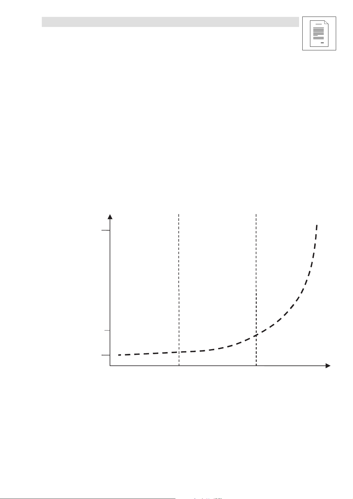
1.2 Cost situation for EMC measures
Design phase Commissioning
100
Cost factor
10
1
Fig. 1 Project of EMC measures - cost d evelopment
Any required EMC measure must be integrated as early as during the design phase.
phase
Operating
phase
Time of implementation
l
Considering the EMC measures during the design phase results in considerable cost saving. In the
commissioning and operating phase these costs rise considerably.
EDBEMV EN 1.3
3
Page 6

EMC - legal foundation
Show/Hide Bookmarks
2 EMC - legal foundation
The legal foundation is the EMC Directive and its implementation by the respective EU member
states’ existing national law. In Germany, this is the German EMC Act, in force since 1996, and the
rules and regulations of its application.
The gist of its central requirement is that the operation of electrical and electronic equipment,
systems, or devices must not produce any impermissible mutual interferences.
Within the meaning of the requirements arising from the EMC Directive, there may be varying
interpretations at the time of product rating. The EMC behaviour of an electrical or electronic device
is essentially determined by
z
its interference emissions
z
its immunity to interference.
As far as the EMC characteristic s of a product are concerned, the manufacturer and / or the party
introducing it to the market is always obliged to meet special requirements with respect to
information. In their documentation (Operating Instructions), Lenze specify conformity to standards
and provide detailed installation instructions.
2.1 EMC product standard for variable-speed electrical drives
EN 61800-3 defines limit values and test procedures for drives and
z
covers the electrical drive system from the mains connection to the motor shaft end,
z
takes into consideration
– various distribution channels,
– various environments (residential / industrial),
– external connections and internal interfaces.
It defines assessment criteria for the operational behaviour on interference at the external
connections and internal interfaces and includes requirements to be met by the immunity to
interference in accordance with the environment at the plac e of use.
2.2 Place of use
The place of use is divided into two so-called environments:
Environment 1
Residential, business, and industrial: Environment that contains residential areas and facilities that
are connected directly without adapter transformer to a low-voltage mains that supplies residential
buildings.
Environment 1
Industrial: Facilities that are not directly connected to a low-voltage mains supplying residential
areas.
4
EDBEMV EN 1.3
l
Page 7
EMC - legal foundation
Show/Hide Bookmarks
2.3 EN 61800-3 requirements on interference emission
EN 61800-3 defines limit values depending on the environments at the place of use.
For the low-frequency range (< 9 kHz), limit values are defined for
z
harmonic s (EN 61000-3-2/ -12)
z
voltage fluctuations / flickering (EN 61000-3-3/-11)
z
mains voltage commutation notches (EN 60146-1-1)
For the high-frequency range (> 9 kHz), limit values are defined for
z
interference voltages (EN 55011 or EN 55022)
z
interfering radiations (EN 55011 or EN 55022)
In addition to the functional task of a component, machine or system, EMC measures, too, must be
taken into consideration as early as during the planning phase. Only during that stage c an EMC
measures be integrated with maximum cost efficiency. During the test phase or as late as during
operation, the possible measures are drastically reduced, resulting in rising costs (see section 1.2).
The ultimately responsible for adherence to the standards (CE mark) is the party who ” introduces
a machine or system to the market” . It is therefore essential that the manufacturer or builder of a
machine or system takes steps to ensure as early as during component acquisition that EMC
measures are considered and information is available as to how to reach compliance with the EMC
Directive.
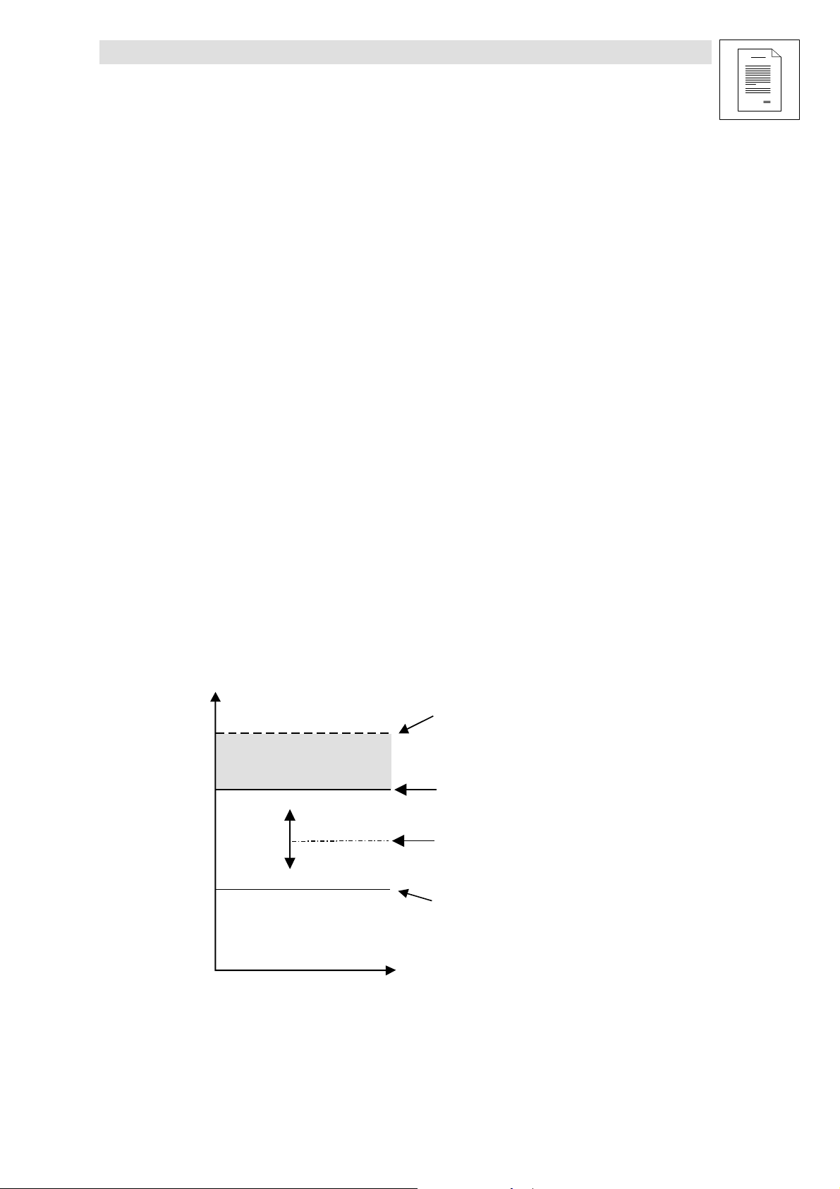
Interference level
Tolerance range of
immunity to interference
Interference level causing malfunctions:
Malfunctions of devices or systems
Interference level causing no malfunction
(threshold of immunity):
Standardised level of immunity to interference, up to
which a device or system operates without malfunction
Electromagnetically compatible interference level:
Maximum interference level to be expected in any
environment
Interfering radiation limit:
Maximum interfering radiation level which a
device is allowed to emit
Fig. 2 Requirements for interference emission
l
Frequency
EDBEMV EN 1.3
5
Page 8
Interference ranges for frequency inverters
Show/Hide Bookmarks
3 Interference range of frequency inverters
Overview - frequency inverter interference ranges
Mains current harmonics Interference emission
Conducted Conducted Non-conducted (interference)
Frequency range 0 ... 2.5 m 150 kHz ... 30 MHz 30 MHz ... 1 GHz
Cause Non-sinusoidal mains current High-speed switching of output
Effect
Countermeasures
Standards f or limit class
A (industrial)
Standards f or limit class
B (residential)
•
Increased eff. mains current
•
Additional temperature rise in
mains supply transformers
•
Mains choke
•
PFC (Power-Factor-Correction)
EN 61800-3 EN 55011 EN 55011
EN 61000-3-2: Electrical
equipment
•
Mains current < 16 A or
•
Input power < 1 kW
stages and switched-mode power
supplies. Their electrical
connection results in interference
injection to the mains input.
Interference injection on the
mains side into other
consumers on the same mains
(electrical connection)
RFI filter on the mains side
(internal / external)
EN 55022 EN 55022
The switching edges of output stages
with high rate of voltage rise include
high-frequency harmonics that, as
”transmitters”, emit interferences in
connection with the mot or cables
(aerials).
Interfering radiation of inverter and motor
cable to other nearby high-resistance
control signal cables
•
Shielding of inverter and motor cable
•
Continuous shield
•
Optimum shield connection
•
Short unshielded wire ends
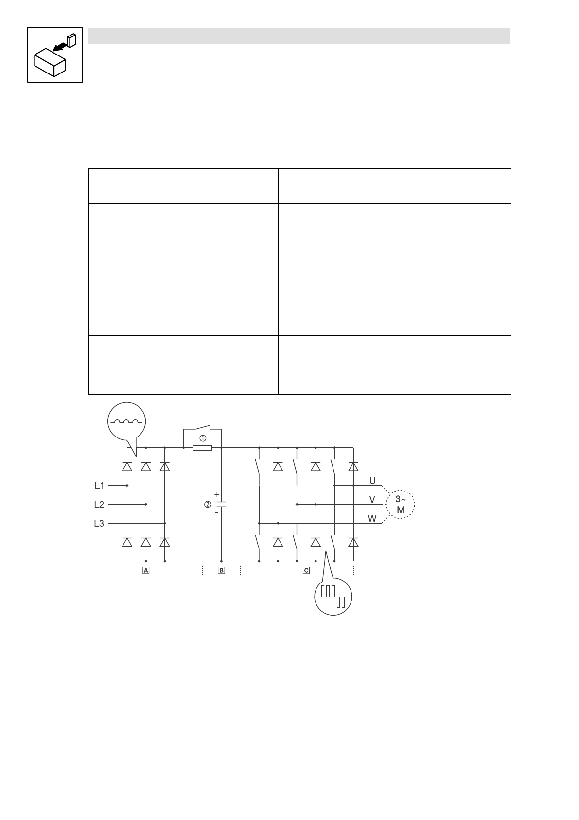
Fig. 3 Pow er unit of the DC bus inverter
Uncontrolled input rectifier
DC b us
Three-phase inverter
c Power-on protection
d DC bus capacitors
6
EDBEMV EN 1.3
l
Page 9

EMC interference injections
Show/Hide Bookmarks
4
EMC interference injections
The injection of EMC interference is characterised by different coupling mechanisms. The
respective coupling mechanism is the “transmission path“ between interference source and
potentially susceptible equipment.
Thereare4differentcoupling mechanisms:
E l e c t r o m a g n e t i c e n v i r o n m e n t
( i n t e r f e r e n c e s o u r c e )
C o n d u c t i v e
c o u p l i n g
C a p a c i t i v e
c o u p l i n g
I n d u c t i v e
c o u p l i n g
R a d i a n t
c o u p l i n g *
*
Combination of capacitive and inductive coupling
Fig. 4 EMC: Coup ling mechanisms
The degree of intensity of the interference injection may be reduced by various different measures:
At the transmitter
•
Shielding
•
Filters
At the coupling mechanism
•
Shielding
•
Topology
•
Optical waveguide (electrical isolation)
At the receiver
•
Shielding
•
Filters
•
Circuitry arrangement
R e c e i v e r ( p o t e n t i a l l y
s u s c e p t i b l e e q u i p m e n t )
I n t e r f e r e n c e s o u r c e
I n t e r f e r e n c e s o u r c e
I n t e r f e r e n c e s o u r c e
( e m i t t e r )
( e m i t t e r )
( e m i t t e r )
C o u p l i n g m e c h a n i s m
C o u p l i n g m e c h a n i s m
C o u p l i n g m e c h a n i s m
( p a t h )
( p a t h )
( p a t h )
P o t e n t i a l l y s u s c e p t i b l e
P o t e n t i a l l y s u s c e p t i b l e
P o t e n t i a l l y s u s c e p t i b l e
e q u i p m e n t ( r e c e i v e r )
e q u i p m e n t ( r e c e i v e r )
e q u i p m e n t ( r e c e i v e r )
l
EDBEMV EN 1.3
7
Page 10

EMC interference injections
g
Show/Hide Bookmarks
4.1 Conductive coupling
Conductive coupling is the result of several power circuits using the
same line sections.
U2
U1
Interference voltage
4.2 Capacitive coupling
Coupling current
U1
U2
PLC
Causes
•
Frame and earth connections
•
Coupling of various power circuits
•
Earth loops
Countermeasures
•
Short joint reference conductors
•
Electrical isolation of the systems (transformer, relays ... )
Capacitive coupling occurs due to the impact of electrical fields on
adjacent cables.
Causes
•
High- voltage / signal cables
•
Switching of inductances
•
Parallel cable arrangement
Countermeasures
•
Increase distance between cables
•
Reduce parallel cable length
•
Shield cables
•
Reduce rate of voltage rise
4.3 Inductive coupling
Circuit 1
Couplin
U
Circuit 2
8
inductance
EDBEMV EN 1.3
Inductive coupling occurs due to the impact of magnetic fields o n
I
adjacent cables.
Causes
•
High-voltage current switching
•
Switching of capacitances
•
Parallel cable arrangement
Countermeasures
•
Increase distance between cables
•
Reduce parallel cable length
•
Twist forward and return conductors
•
Reduce rate of current rise
l
Page 11

5 Shielding
Show/Hide Bookmarks
5.1 Shield connection
The quality of shielding is determined by:
z
a good shield connection
– a contact surface as large as possible
z
a low resistance:
– Only use shields with tin-plated or nickel-plated copper braids!
– Shields of steel braid are not suitable.
5.2 Shielding - what do you need to consider?
Shielding
z
Always connect the shield to the conductive and grounded mounting plate with a surface as
largeaspossibleviaaconductiveclamp.
z
Connect the shield directly to the corresponding device shield sheet.
z
Do not only c onnect the shield to the cable rail.
z
The unshielded cable ends must be as short as possible.
•
Short unshielded cable ends
•
Terminals must be separated, minimum distance: 100 mm
•
Minimum distance between the shield clamps for control cable and
motor cable: 50 mm
Fig. 5 Shielding for frequency inverters
l
EDBEMV EN 1.3
9
Page 12

Shielding
Show/Hide Bookmarks
5.3 Motor cables
z
If the motor cable must be interrupted by chokes or terminals, the unshielded cable must not
be longer than 40 - max. 100 m (depending on the cable cross-section).
z
If the motor cable must be interrupted by contactors, switches, or terminals, these must be
separated from the other components (with a min. distance of 100 mm).
z
In case of cable lengths up to 500 mm a second shield (shield connection) is not required.
Motor supply cable
max. 500mm
Braid
Large-surface
contact of
cable shield
5.4 Control cables
z
The cables of the analog and digital inputs and outputs must be shielded. If short (up to 200
mm) and unshielded c ables are used, they must be twisted.
z
In case of the analog cables the shield must only be connected to the controller.
z
In unfavorable conditions (very long cable, high interferences) it is possible in case of analog
cables to connect one shield end to PE via a capacitor (e.g. 10 nF/250 V) to have a better
shielding effect (see sketch).
z
In case of digital cables the shield must be connected on both sides.
Cable gland
Heat-shrinkable tube
Cable gland acc. to EMC with
high degree of protection
z
The shields of the control cables must have a minimum distanc e of 50 mm to the shield
connections of the motor cables and DC cables.
Fig. 6 Shielding of long, analog control cables
10
EDBEMV EN 1.3
l
Page 13

Arrangement according to EMC requirements
Show/Hide Bookmarks
6 Arrangement according to EMC requirements
6.1 Specification for shielded cables for arrangement according to EMC
6.1.1 Motor cable design
z
Only use shielded, four-core motor cable (core U, V, W, PE and overall shield).
z
Cables with a YCY copper braid have a good shielding effect, cables with SY steel-tape
armour are less suitable (high shield resistance).
z
The contact ratio of the braid:
– At least 70% to 80% with overlap angle of 90°.
z
Use low-capacitance cables to reduce the discharge currents.
– The values depend on the cable cross-section.
z
The rated voltage of the motor cable for inverter operation amounts to Uo/ U= 0.6/ 1 kV.
z
The cables used must comply with the required approvals of the application (e.g. UL).
The EMC safety of the connec tion for motor temperature monitoring depends on how the shielded
connecting cables are laid.
EMC safety Type of laying Note
Very good Motor cable and PTC/thermal
contact cable are laid separately
Medium Motor cable and PTC/thermal
contact cable are laid together
with separate shields
Unfavorable Motor cable and PTC/thermal
contact cable are laid together
with a commo n shield
Ideal laying system with very low interference
injections.
Treat PTC/thermal contact cable like a control cable
Laying system is permitted but shows higher
interference injections.
High-energy interference injections!
6.1.2 Cable design for DC connection and brake resistor
6.1.3 Control cable design
l
z
These DC cables must be designed like the motor cable.
– Shielding
– Rated voltage
– Approval
z
Being relatively short, low-capacitance versions are not necessary.
Control cables must be shielded to minimise interferences.
EDBEMV EN 1.3
11
Page 14

Arrangement according to EMC requirements
Show/Hide Bookmarks
6.2 In the control cabinet
6.2.1 Mounting plate characteristics
z
Use mounting plates with an electrically conductive surface (zinc-coated or V2A).
z
Varnished mounting plates are unsuitable, even if the varnish is removed from the contact
surfaces.
z
When using several mounting plates, make a conductive connection over a large surface (e.g.
using grounding strips).
6.2.2 Mounting of the components
z
Connect the controller and RFI filter to the grounded mounting plate with a surface as large as
possible.
z
No DIN rail mounting!
6.2.3 Correct cable installation
z
Control cables and mains cables must be separated from the motor cable.
z
Install terminals for the motor cables e.g. at the control cabinet entry with a minimum
distance from the other terminals of at least 100 mm.
z
The cables must always be installed close to the mounting plate (reference potential), as
loose cables act like aerials.
z
Thecablesmustberoutedinastraightlinetotheterminals(avoid“tangleofcables”)!
z
Use a separate cable duct for mains cables and control cables. Do not mix different cable
types in one cable duct.
z
Never lay motor cables in parallel with mains cables and control cables.
z
Cross the motor cable vertically with mains cables and control cables.
z
Twist unshielded cables of the same circuit (go-and-return line) and ensure that the area
between go-and-return-line is as small as possible.
z
Reduce coupling capacitances and inductances due to unnecessary cable lengths and
reserve loops.
z
Short-circuit cable ends of unused cables to the reference potential.
6.2.4 Earth connection
z
Connect all components (controller, RFI filter, filter, chokes) to a central earthing point (PE rail).
z
Set up a star-shape earthing system.
z
Comply with the corresponding minimum cable cross-sections.
12
EDBEMV EN 1.3
l
Page 15

Arrangement according to EMC requirements
Show/Hide Bookmarks
6.2.5 Installing the cables within the control cabinet
Separation of the “ hot” motor cable from control cables, signal cables and mains cables:
z
Never install motor and signal cables in parallel. Crossings must be laid at right angles.
z
Arrange the conductors of a 24 V power supply unit close together along the whole length so
that no loops may occ ur.
Mains fuses Mains contactors
Fuses
Filters on
mains side
Filters on
mains side
24V power supply unit
PLC
Cable duct for signal and mains cables
Fig. 7 Cable routing in the control c abinet
Relay
Connection terminals
8200
vector
Motor
contactors
8200
vector
Cable duct for motor cables
l
EDBEMV EN 1.3
13
Page 16

Arrangement according to EMC requirements
Show/Hide Bookmarks
6.3 Wiring according to EMC outside the control cabinet
6.3.1 General information
Notes for cable laying outside the control cabinet:
z
The longer the cables the greater the space between the cables.
z
In case of parallel cable routing of cables with different types of signals it is possible to
minimise the interferences by means of a metal barrier or separated cable ducts.
Cover
Communication cables
Cover
Separator
without
cutout
Cable duct
Measuring cables
Analog cables
Control cables
Signal cables
Fig. 8 Cable routing with sep arator Fig. 9 Cable routing with sep arate cable duc t
Power cables
6.3.2 Wiring on the mains side
z
It is possible to connect the controller, mains choke or RFI filter to the mains via single cores
or unshielded cables.
z
The cable cross-sec tion must be rated for the assigned fuse protection (EN 0160).
6.3.3 Wiring on the motor side
z
Use shielded, low-capacitance motor cables only.
Stop!
The motor cable is highly susceptible to interferences. Hence the following applies:
The motor cable must not contain any further cables (e.g. for brake control,
separate fans etc.).
One exception is the temperature monitoring cable of the motor.
Power cables
z
Shield the cable for temperature monitoring of the motor (PTC or thermal contact) and
separate it from the motor cable.
14
EDBEMV EN 1.3
l
Page 17

Limiting harmonic currents in the supply mains
Show/Hide Bookmarks
7 Limiting harmonic currents in the supply mains
Power consumption of a standard inverter
The input circuit of a frequency inverter with DC voltage bus generally consists of an uncontrolled
rectifier and the DC bus capacitance made up of electrolytic capacitors.
Single-phase bridge-connected rectifier without choke Single-phase bridge-connected rectifier with choke
ohne Drosse l
mit Drossel
U - I
t
U - I
t
Non-sinusoidal input currents of frequency inverters are referred to as harmonic currents (mains
harmonic s) and can ”pollute” the supply system and have an impact on other consumers.
European Standard EN 61000-3-2 ensures the quality of public mains systems, specifying limit
values to restrict mains loads (background: increasing number of non-linear consumers).
The standard only applies to public mains systems. Mains systems which have their own
transformer station as common in industry are not public. The standard does not apply to them.
This affects units (inverters) with an input current (mains current) of up to 16 A or with input powers
of up to 1 kW.
If a machine or system consists of several components, the limit values apply to the entire machine
or system.
l
EDBEMV EN 1.3
15
Page 18

Limiting harmonic currents in the supply mains
V
V
V
Show/Hide Bookmarks
The listed measures ensure that inverters with DC voltage bus adhere to the limit values according
to EN 61000-3-2. The machine / system manufacturer is responsible for the compliance with the
regulations of the machine:
Connection voltage Power Measure
[V] [kW]
1/N/PEAC 230
3/PEAC 230
3/PEAC 400
0.25
0.37
0.55
0.75
0.55
0.75
0.55
0.75
Use assigned mains choke
Use active filter/PFC
Use assigned mains choke
16
EDBEMV EN 1.3
l
Page 19

Compensation equipment
Show/Hide Bookmarks
8 Compensation equipment
Interactions with compensation equipment
Controllers only consume a very small fundamental reactive power from the AC mains. Therefore
compensation is not necessary.
Please consult the supplier of the compensation equipment in due time.
Stop!
Where higher-power machines in old industrial systems are updated with standard
inverters, steps must be taken to ensure that the old compensation systems are
equipped with chokes or replaced by new ones (with chokes).
The harmonic currents generated by the inverter (specifically 5 and 7) may cause
the capacitor currents to assume values that would very quickly destroy the
capacitor batteries, leading to a complete compensation breakdown.
l
EDBEMV EN 1.3
17
Page 20

Equipotential bonding
Show/Hide Bookmarks
9 Equipotential bonding
Potential differences occur in:
z
Spatially separate mounting plates within a control cabinet
z
Several control cabinets spatially distributed within the system
z
Use of decentralised controllers (motec/starttec)
z
Components fed from different supplies
Existing potential differences cause a flow of compensating currents which amount up to several
amperes for short periods.
The effects of potential differences are as follows:
z
Interference of control signals
z
Interference of communication systems (error frames)
z
Destruction of electronic components (e.g. interfaces)
The following measures are suitable to reduce potential differences:
z
Establish equipotential bonding between mounting plates/control cabinets with the help of
large-surface large-contact earthing strip.
Fig. 10 Earthing strip for eq uipotential bonding
z
Set up supplies with joint reference potential
z
Provide large-surface shield contact surfaces
z
Provide an electrical isolation (optical or isolating transformer) if above measures do not
suffice.
Fig. 11 Improving the shielding effec t inside the control c abinet
18
EDBEMV EN 1.3
L
Page 21

Operation with e.l.c.bs
Show/Hide Bookmarks
10 Operation with e.l.c.bs (earth-leakage circuit breakers)
Different protection measures are suitable to protect humans and animals (DIN VDE 0100).
Note the following when using earth-leakage circuit breakers:
z
Pulse-current sensitive e.l.c.bs in systems with controllers with single phase mains
connection (L1/N)
z
Universal-current sensitive e.l.c.bs in systems with controllers with three-phase mains
connection (L1/L2/ L3)
z
E.l.c.bs must only be installed between mains supply and controller.
E.l.c.bs can be activated although not wanted by
z
Capacitive leakage currents of the cable shields during operation (especially with long,
shielded motor cables),
z
Mains connection of several controllers at the same time,
z
Use of additional RFI filters.
The intensity of these capacitive earth currents depends on the following factors:
z
1AC- or 3AC frequency inverter, phase failure
Danger!
The controllers are internally equipped with a mains rectifier. In the event of a
short-circuit to frame, an earth leakage current can block the tripping of
AC-sensitive and / or pulse-current sensitive e.l.c.b. and thus cancel the protective
function for all equipment operated on this e.l.c.b..
z
Inverter-internal EMC elements
z
Length and type of motor cable
z
Mains voltage level
z
Switching frequency level
z
Winding structure in the motor
z
Installed filters on the mains / motor side
z
Mains switch make and break characteristics
Remedies
z
Low-capacitance and short motor cables
z
Increase switching frequency (e.g. 16 kHz)
z
Switch mains phases simultaneously (e.g. contactor)
z
Provide supply via isolating transformer
l
EDBEMV EN 1.3
19
Page 22

Operation with e.l.c.bs
Show/Hide Bookmarks
Symbol on the e.l.c.b. E.l.c.b. types
AC-sensitive earth-leakage circuit breaker (e.l.c.b., type AC):
Not suitable for controllers; no longer used.
Pulse-current-sensitive earth-leakage circuit breaker (e.l.c.b., type A)
Single-phase-supply controllers; commercially available
Universal-current-sensitive earth-leakage circuit breaker (e.l.c.b., type B)
Single-phase and three-phase-supply controllers
20
EDBEMV EN 1.3
l
Page 23

Leakage current for portable systems
Show/Hide Bookmarks
11 Leakage current for portable systems
Frequency inverters with internal or external radio interference suppression filters usually feature a
leakage current to the PE potential, higher than AC 3.5 mA or DC 10 mA.
This requires solid connection for protection (refer EN 50178/5.2.11.1) and must be specified in the
operating documentation.
Where a solid connection is not realistic in the case of a portable consumer although the leakage
current to the PE potential is above AC 3.5 mA or DC 10 mA, a suitable countermeasure would be
the installation of an additional two-winding transformer (isolating transformer) into the power
supply, with the PE conductor being connected to the drive’s PE’s (filter, inverter,motor, shields)and
also to one pole of the secondary winding of the isolating transformer.
For 3-phase-supplied units, select a suitable isolating transformer with secondary star connection,
with the star point being connected to the PE conductor.
L1
primary
N
PE
Fig. 12 Installation of a two-wind ing transformer (isolating transformer)
secondary
L1
N1
L2
Filter Inverter
N2
L
U
V
W
N
M
3~
l
EDBEMV EN 1.3
21
Page 24

Notes
Show/Hide Bookmarks
22
EDBEMV EN 1.3
l
Page 25

Notes
Show/Hide Bookmarks
l
EDBEMV EN 1.3
23
Page 26

Notes
Show/Hide Bookmarks
24
EDBEMV EN 1.3
l
 Loading...