

Page 1

USER’S MANUAL
MODELS:
SS504A SS508A
SS604A SS608A
SS604A-3P SS608A-3P
SS610A SS612A-3P
SSi1004A SSi1008A
SSi1010A SSi1012A-3P
Page 2

SimpleServo 500/600/i1000 User Manual Rev 3.4
Copyright ©2001 by AC Technology Corporation
All rights reserved. No part of this manual may be reproduced or transmitted in any form without written
permission from AC Technology Corporation. The information and technical data in this manual are
subject to change without notice. AC Technology Corporation and its Divisions make no warranty of any
kind with respect to this material, including, but not limited to, the implied warranties of its merchantability
and fitness for a given purpose. AC Technology Corporation and its Divisions assume no responsibility for
any errors that may appear in this manual and make no commitment to update or to keep current the
information in this manual.
MotionView, SimpleServo, and all related indicia are either registered trademarks or trademarks of AC
Technology Corporation in the United States and other countries.
This document printed in the United States of America.
2
Page 3

SimpleServo 500/600/i1000 User Manual Rev 3.4
TABLE OF CONTENTS
1 GENERAL INFORMATION ................................................................................................................7
2 SPECIFICATIONS ..............................................................................................................................8
2.1 Electrical Characteristics............................................................................................................................8
2.2 Environment.................................................................................................................................................8
2.3 Dimensions and Weight .............................................................................................................................9
2.4 Operating Modes SS500/600 drives ........................................................................................................9
2.5 Operating Modes SSi1000 drives.............................................................................................................9
2.6 SSi1000 drives features...........................................................................................................................10
2.7 Connections and I/O.................................................................................................................................11
3 DIMENSIONS.................................................................................................................................... 12
3.1 SS500 Series Dimensions.......................................................................................................................12
3.2 SS604/SS608/SSi1004/SSi1008 Series Dimensions..........................................................................13
3.3 SS610/SS612-3P/SSi1010/SSi1012-3P Dimensions with Heat Sink Fan Kit Installed..................14
3.4 Suggested Clearance for Cooling Air Circulation (All Models)...........................................................15
4 INSTALLATION ................................................................................................................................16
4.1 Start Up.......................................................................................................................................................17
4.2 Mounting.....................................................................................................................................................17
4.3 Wiring.......................................................................................................................................................... 17
4.4 Shielding and grounding ..........................................................................................................................18
4.4.1 General guidelines .................................................................................................................... 18
4.4.2 EMI Protection ...........................................................................................................................18
4.4.3 Enclosure.................................................................................................................................... 18
4.5 Line filtering................................................................................................................................................18
4.6 Heat sinking ...............................................................................................................................................19
4.7 Line fusing..................................................................................................................................................19
5 SIMPLESERVO CONNECTIONS..................................................................................................... 20
5.1 External Connectors .................................................................................................................................20
5.1.1 TB501 - Power, Motor, and Fuse Connections ....................................................................20
5.1.2 TB502 - Analog/Digital I/O Terminal Block............................................................................ 21
5.1.3 Encoder feedback .....................................................................................................................23
5.1.4 TB504 - Motor Feedback Input ...............................................................................................23
5.1.5 TB505 - Serial Communications Port..................................................................................... 25
5.1.6 TB506 - Controller Interface (SS500/600 drives) ................................................................. 26
5.1.7 TB506 - Encoder repeat and analog input connections (SSi1000 drives)........................27
5.1.8 Connectors and Wiring Notes .................................................................................................28
5.2 Digital I/O details (SS500/600 drives)....................................................................................................29
5.2.1 Step and Direction/ Master Encoder Inputs ..........................................................................29
5.2.2 Digital outputs ............................................................................................................................ 29
5.2.3 Digital inputs ..............................................................................................................................30
5.3 Digital I/O details (SSi1000 drives).........................................................................................................32
5.3.1 Digital inputs ..............................................................................................................................32
5.3.2 Digital outputs ............................................................................................................................ 32
5.4 Analog I/O details......................................................................................................................................35
5.4.1 Analog reference input .............................................................................................................35
5.4.2 Analog output............................................................................................................................. 35
5.5 Communication interfaces (SS500/600 drives) ....................................................................................35
5.6 Communication interfaces (SSi1000 drives).........................................................................................35
5.6.1 RS232 interface......................................................................................................................... 35
5.6.2 RS485 interface......................................................................................................................... 36
5.6.3 Ethernet interface...................................................................................................................... 37
3
Page 4

SimpleServo 500/600/i1000 User Manual Rev 3.4
5.7 Motor Selection .........................................................................................................................................38
5.7.1 Setting Up motor .......................................................................................................................38
5.8 Using custom motor..................................................................................................................................39
5.8.1 Setting custom motor parameters...........................................................................................39
5.8.2 Autophasing ...............................................................................................................................40
5.8.3 Custom Motor Data Entry ........................................................................................................40
6 SS500/600 PROGRAMMABLE FEATURES AND PARAMETERS ................................................45
6.1 Motor Group...............................................................................................................................................45
6.2 Parameters Group ...................................................................................................................................45
6.2.1 Drive operating modes .............................................................................................................45
6.2.2 Current Limit ..............................................................................................................................47
6.2.3 Peak current limit.......................................................................................................................47
6.2.4 Analog input scale( Current scale) .........................................................................................47
6.2.5 Analog input scale (Velocity scale)......................................................................................... 48
6.2.6 ACCEL/DECEL Limits (Velocity mode only) .........................................................................48
6.2.7 Reference (Velocity mode only)............................................................................................. 48
6.2.8 Reset Option .............................................................................................................................. 48
6.2.9 Steps per Revolution (Step and Direction mode only).........................................................48
6.2.10 Step input type (Step and Direction mode only) .................................................................. 48
6.3 I/O Group....................................................................................................................................................49
6.3.1 Programmable digital input...................................................................................................... 49
6.3.2 Programmable digital output....................................................................................................49
6.3.3 Analog output............................................................................................................................. 49
6.3.4 Analog output current scale (Volt/amps) ..............................................................................49
6.3.5 Analog output velocity scale (mV/RPM) ................................................................................ 50
6.3.6 Analog input offset parameter .................................................................................................50
6.3.7 Analog input dead band ...........................................................................................................50
6.3.8 Adjust analog voltage offset ....................................................................................................50
6.4 Velocity Limits Group................................................................................................................................50
6.5 Position limits.............................................................................................................................................50
6.6 Compensation group ................................................................................................................................51
6.6.1 Velocity Loop Filter ...................................................................................................................51
6.6.2 Position Loop Filter ...................................................................................................................51
6.7 Faults Group ..............................................................................................................................................52
6.8 Tools Group ...............................................................................................................................................52
6.8.1 Run Panel................................................................................................................................... 52
6.8.2 Drive monitor.............................................................................................................................. 52
6.8.3 Oscilloscope tool .......................................................................................................................52
7 SSI10XX PROGRAMMABLE FEATURES AND PARAMETERS ...................................................53
7.1 Motor folder................................................................................................................................................53
7.2 Parameters.................................................................................................................................................53
7.2.1 Drive mode................................................................................................................................. 53
7.2.2 Current Limit ..............................................................................................................................53
7.2.3 Peak Current Limit .................................................................................................................... 53
7.2.4 Autoboot .....................................................................................................................................53
7.2.5 Feedback loss detection ..........................................................................................................53
7.2.6 RS485 configuration .................................................................................................................53
7.2.7 Group ID .....................................................................................................................................54
7.2.8 IP properties (command button) ............................................................................................. 54
7.3 I/O................................................................................................................................................................54
7.3.1 Outputs 1,2,3,4 functions........................................................................................................54
7.3.2 Hard limit switches action. .......................................................................................................54
7.4 Limits...........................................................................................................................................................54
7.4.1 Position Limits............................................................................................................................ 54
4
Page 5

SimpleServo 500/600/i1000 User Manual Rev 3.4
7.5 Compensation ...........................................................................................................................................55
7.5.1 Velocity Loop filter.....................................................................................................................55
7.5.2 Position Loop filter.....................................................................................................................55
7.6 Indexer Program .......................................................................................................................................56
7.7 Security.......................................................................................................................................................56
7.8 Faults Group ..............................................................................................................................................56
7.9 Tools ...........................................................................................................................................................56
7.9.1 Drive monitor.............................................................................................................................. 56
7.9.2 Oscilloscope tool .......................................................................................................................56
8 DIAGNOSTICS .................................................................................................................................57
8.1 Diagnostic LED’s....................................................................................................................................... 57
8.1.1 Front panel LEDs ......................................................................................................................57
8.1.2 Bottom side LEDs .....................................................................................................................57
8.2 Faults ..........................................................................................................................................................58
8.2.1 Fault Event .................................................................................................................................58
8.2.2 Fault Reset................................................................................................................................. 58
9 OPERATION .....................................................................................................................................59
9.1 Minimum Connections..............................................................................................................................59
9.2 Configure the SS500/600 SimpleServo drives .....................................................................................59
9.3 Configure SSi1000 SimpleServo drives ................................................................................................60
9.4 Enabling the SS500/600 drives. .............................................................................................................62
9.5 Enabling SSi1000 drives..........................................................................................................................63
9.6 Tuning in velocity mode ...........................................................................................................................64
9.7 Tuning in position PVFF mode................................................................................................................65
9.8 Tuning in position P+V mode. .................................................................................................................66
10 SAMPLE MOTOR RESPONSES FOR VARIOUS GAIN SETTINGS .............................................. 67
10.1 Motor response to gain settings (Velocity mode).................................................................................67
10.1.1 Low P-gain.................................................................................................................................67
10.1.2 Right P-gain...............................................................................................................................68
10.1.3 I-gain too high ...........................................................................................................................69
10.1.4 Correct P-gain and I-gain........................................................................................................ 70
10.2 Motor response to gain settings (Position Mode).................................................................................71
10.2.1 PVFF mode P-gain / D-gain relationship. Non-optimal setting.......................................... 71
10.2.2 PVFF mode P-gain / D-gain relationship. Optimal setting. ................................................72
10.2.3 VFF gain effect .........................................................................................................................73
11 SYSTEM CONNECTION EXAMPLES .............................................................................................75
11.1 System with external motion controller..................................................................................................75
11.2 Simple Torque and Velocity System ......................................................................................................76
11.3 Position Follower.......................................................................................................................................78
11.4 Indexer connections options for position follower ................................................................................79
12 TROUBLESHOOTING...................................................................................................................... 80
13 WARRANTY AND OTHER INFO ..................................................................................................... 82
5
Page 6
SimpleServo 500/600/i1000 User Manual Rev 3.4
Safety Warnings
• The symbol shown at left indicates an important safety consideration. Please read this
manual carefully before performing any of the procedures contained herein. Failure to follow
these instructions may result in equipment damage, fire, severe injury, or fatality.
• Have a qualified electrical maintenance technician install, adjust and service this equipment.
Follow the National Electrical Code and all other applicable electrical and safety codes,
including the provisions of the Occupational Safety and Health Act (OSHA), when installing
equipment.
• The symbol shown at left indicates additional information, shortcuts, or tips that do not affect
the safe operation of the drive.
• Reduce the chance of an electrical fire, shock, or explosion by proper grounding, overcurrent protection, thermal protection, and enclosure. Follow sound maintenance procedures.
• It is possible for a drive to run at full speed as a result of a component failure. Please
ensure that a master switch has been placed in the AC line to stop the drive in an
emergency.
WARNING!
Hazard of electrical shock! Circuit potentials are at 115 VAC or 230 VAC above earth
ground. Avoid direct contact with the printed circuit board or with circuit elements to prevent
the risk of serious injury or fatality. Disconnect incoming power and wait 60 seconds before
servicing drive. Capacitors retain charge after power is removed.
6
Page 7

SimpleServo 500/600/i1000 User Manual Rev 3.4
1 General Information
• The AC Tech SimpleServo family of servo amplifiers is an economical solution to today’s complex
motion-control needs. The SimpleServo combines a Digital Signal Processor (DSP), controller, heat
sink and power supply in one standalone, DIN-rail mountable or panel-mounted unit. The
SimpleServo can be operated as a stand-alone unit or as a digital amplifier.
• The SimpleServo controls brushless motors with a high switching (carrier) frequency for virtually silent
operation. Most servo motors used today require high precision control and a smooth, sinusoidally
commutated signal. An on-board DSP provides commutation by generating the three-phase sine
wave, using feedback information from an optical encoder.
• The SimpleServo will accept feedback from an encoder that includes Hall sensor feedback
information. It accepts commands from a variety of sources, including analog voltage, PWM and
internal reference signals. The control will operate in current (torque) mode, velocity mode, or position
(step and direction) mode. Upon initial start up, the motor is commutated using the hall sensors—for
the first two or three mechanical degrees of motor rotation—to map the encoder; the Hall-effect
information is unnecessary thereafter.
• The SimpleServo’s built-in RS-232 serial communications port and SimpleServo control program,
MotionView™, make programming extremely simple. In fact, you could be up and running in less than
thirty minutes! Each SimpleServo unit is an amplifier, power supply, controller and heat sink
integrated into a single standalone package. The SimpleServo will only accept an encoder with Hall
or an encoder with hall-commutation tracks encoded on the feedback device.
7
Page 8
SimpleServo 500/600/i1000 User Manual Rev 3.4
2 Specifications
2.1 Electrical Characteristics
Drive
SSX04 6A 4 8 90 – 240
SSX08 12A 8 14 90 – 240
SSX10 15A 10 20 90 – 240
SSX12-3P 19A 12 20 90 – 240
Notes:
“-3P” = 3-phase input power models
* Phase RMS current. Peak current allowed for up to 2 Sec.
Applies to all models:
AC Output Voltage Range (Sinusoidal, Three-Phase) 0–240 VAC RMS
Minimum Output Voltage Range 0 – 340 VAC
Acceleration Time Range (Zero to Max Speed) 0.1 – 5000000 Rpm/sec
Deceleration Time Range (Max Speed to Zero) 0.1 – 5000000 Rpm/sec
Speed Regulation (typical) ± 1 RPM
Input Impedance (+REF to COM and +REF to -REF) 47 kohms
Power Device Switching Frequency (sinusoidal commutation) 16 kHz
Encoder power supply (max) +5 VDC @ 300 mA
Maximum encoder feedback frequency 2.1 MHz
2.2 Environment
Vibration
SS500 Series 0.1 G (all frequencies)
SS600 and SS1000 Series 0.5G max (20 – 50 Hz)
0.1G max (>50 Hz)
Ambient Operating Temperature Range 0 to 40ºC
Ambient Storage Temperature Range -10 to 70ºC
Humidity 5 – 90% non-condensing
Altitude 1500 m/5000 ft (derate by 1% per 300m
Maximum
Continuous
Current (AC in)
(1000 ft) above 1500m (5000 ft))
Continuous
Phase
Current
(AC Amps)
Peak*
Current
(AC Amps)
Input Voltage
(±10%, 50-60 Hz)
(VAC)
8
Page 9
SimpleServo 500/600/i1000 User Manual Rev 3.4
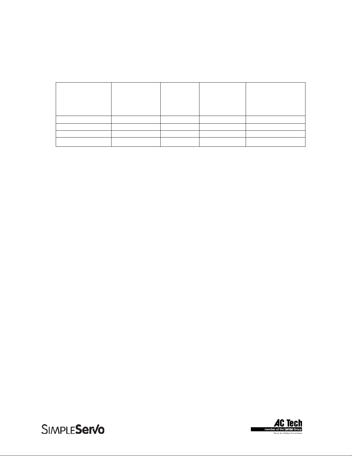
2.3 Dimensions and Weight
Model
Dimension
Height (inches) 6.50 7.80 6.50 7.80 7.80 7.80
Width (inches) 2.60 2.60 3.80 3.70 4.50 4.50
Depth (inches) 7.50 6.80 7.50 6.80 6.80 6.80
Weight (lbs) 2.5 4.0 3.5 5.0 5.6 5.6
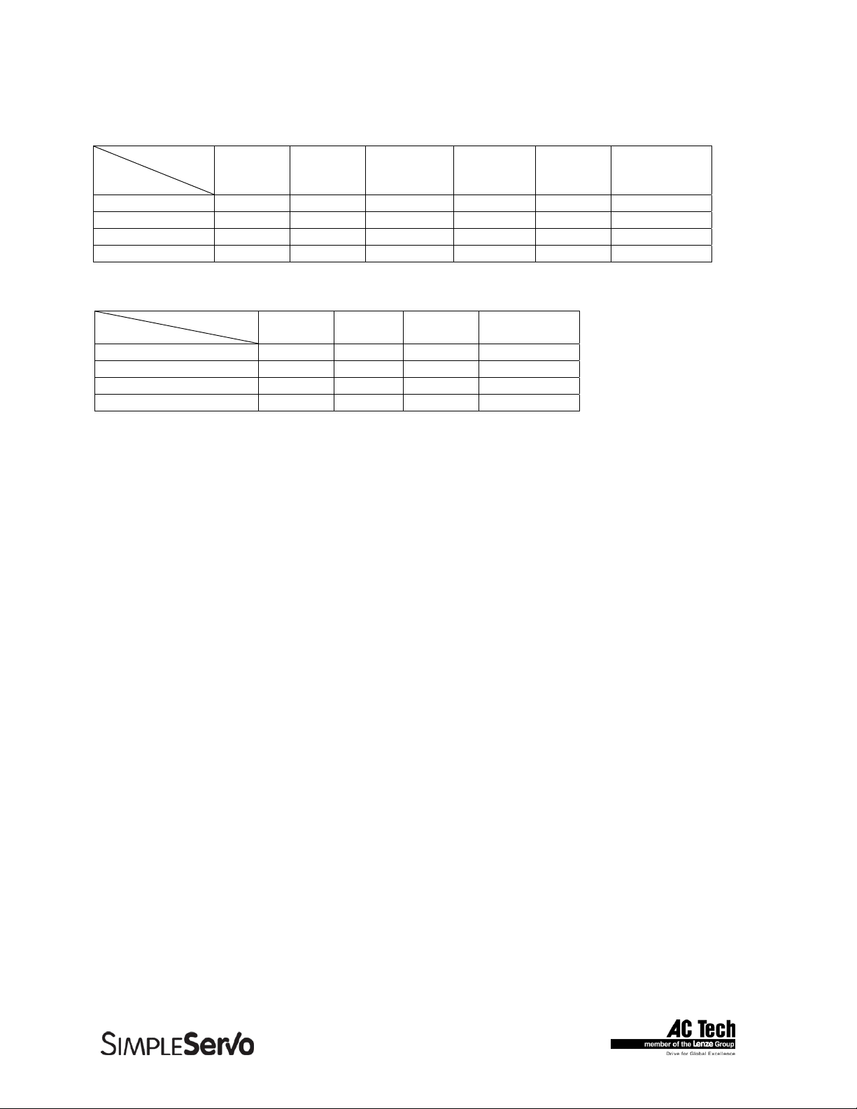
Model
Dimension
Height (inches) 7.80 7.80 7.80 7.80
Width (inches) 2.60 3.70 4.50 4.50
Depth (inches) 6.80 6.80 6.80 6.80
Weight (lbs) 4.0 5.0 5.6 5.6
SS504A SS604A SS508A SS608A SS610A SS612-3P
SSi1004 SSi1008 SSi1010 SSi1012-3P
2.4 Operating Modes SS500/600 drives
• Torque
Reference 0 ± 10 VDC or 0 to 10 VDC, scalable
Torque Range 100:1
Current-Loop Bandwidth up to 3 kHz
• Velocity
Reference 0 ± 10 VDC or 0 to 10 VDC
Accuracy ± 1 RPM
Velocity-Loop Bandwidth up to 400 Hz
Speed Range up to 5000:1 ppr encoder
• Position
Reference Step and direction signals or Master Encoder full quadrature signal (software
selectable).
Minimum Pulse Width 250 nanoseconds
Reference Max frequency 2 MHz
Position-Loop Bandwidth Up to 400 Hz
Accuracy ±1 encoder count
2.5 Operating Modes SSi1000 drives
• Position PIVFF, Position P+V (inner velocity loop)
• Gearing
• Velocity
9
Page 10

SimpleServo 500/600/i1000 User Manual Rev 3.4
2.6 SSi1000 drives features
Indexing
Index resolution 64 bit
Index (position) range from -2
Index generation control Language statements or Host Interface commands
Indexing Incremental, absolute, registered and segmented moves
Motion Queue 32 levels deep
Acceleration/deceleration Linear or S-curved
Move profiles Trapezoidal, Triangular, S-curved
Gearing mode Dedicated inputs for quadrature master encoder reference,
Programmable “on the fly” Gear Ratio and Master Encoder
Scanned events period 256 uS
Registration 2uS reaction time. Current position capture.
User Program
User programming language Statements based.
Program control All major construction: DO-WHILE, WHILE, IF-THEN-ELSE
GOTO, GOSUB. Subroutines supported.
Types supported Typeless. All operands are 64 bit. 32.32 format
Operands representation Floating point.
Translation Multipass compiler
Program Object Bytecode
Execution Java-like virtual bytecode machine
Host Interface support
31
to 231 User Units
PPR via interface or User Program.
Velocity mode Velocity reference, Accel, Decel programmable on the fly via
interface or User Program
Events
Scanned events event on any valid logic expression. Expression can include any
internal System and User variables , I/O states , Flags, arithmetic
and logical expression results.
Tools for program Full featured IDE integrated in MotionView software. Single
Development Step execution capability, Breakpoints, status and variable
WATCH on the fly debug window.
Host Interface transports RS232/485 addressable (32 devices on network), 10/100
Ethernet.
Host Interface commands Unified Set for all interface transports. Could be executed
concurrently with User Program statements.
10
Page 11

SimpleServo 500/600/i1000 User Manual Rev 3.4
Variables
Internal format 64 bit
Number of User Variables 64
Variables resolution 64 bit
System variables resolution 64 bit
Arithmetic and logic functions
Arithmetic functions Addition, Subtraction, Multiplication, Division
Logic and bitwise functions AND, OR, XOR, NOT
2.7 Connections and I/O
All models
RS232 serial interface Standard 9-pin D-shell (DCE)
Encoder Feedback Standard 15-pin D-shell
Encoder buffered repeat in 25-pin D-shell
Power 8-pin removable terminal block (9-pin for 3-P models)
SS500/600 drives
Digital Inputs 1 dedicated (ENABLE), 1 programmable.
Digital Outputs 1 dedicated (READY) , 1 programmable.
Analog Inputs 1 differential analog input. Full range +/- 10V single ended
and +/- 5V differential .Analog input is used for Torque or Velocity reference.
Analog Outputs 1 single ended analog output. +/- 10 V full scale range. Analog output can
be assigned to various drive’s signals.
I/O Controller 15-pin removable terminal block or 25-pin D-shell
Standard 25-pin D-shell
SSi10XX drives
Digital Inputs 5-24V rated 12 digital optically isolated inputs separated into 4 groups.
Each group has common terminal for the group. 2 of 12 inputs are suitable
for connection of master encoder with up to 2 MHz signals’ rate.
Digital Outputs 4 +1 dedicated optically isolated digital outputs. 20mA capability suitable for
24V system control voltages. Both collector and emitter available for each
output at the terminal.
Dedicated output assigned for “READY” function.
Analog Inputs 1 differential analog input. Full range +/- 10V single ended and +/- 5V
differential. Analog Input can be read via System Variable “AIN”.
Analog Outputs 1 single ended analog output. +/- 10 V full scale range. Analog output can
be set by User Program (System Variable AOUT) or via Host Interface.
I/O Connections 25-pin D-shell for digital I/O and 15-pin removable terminal block for analog
input/output connections.
Interfaces
RS-485 4-pin removable terminal block
Ethernet 10/100 RJ-45 modular jack (if equipped)
Windows® Software: MotionViewTM (Windows 95, 98, NT,2000)
11
Page 12
SimpleServo 500/600/i1000 User Manual Rev 3.4
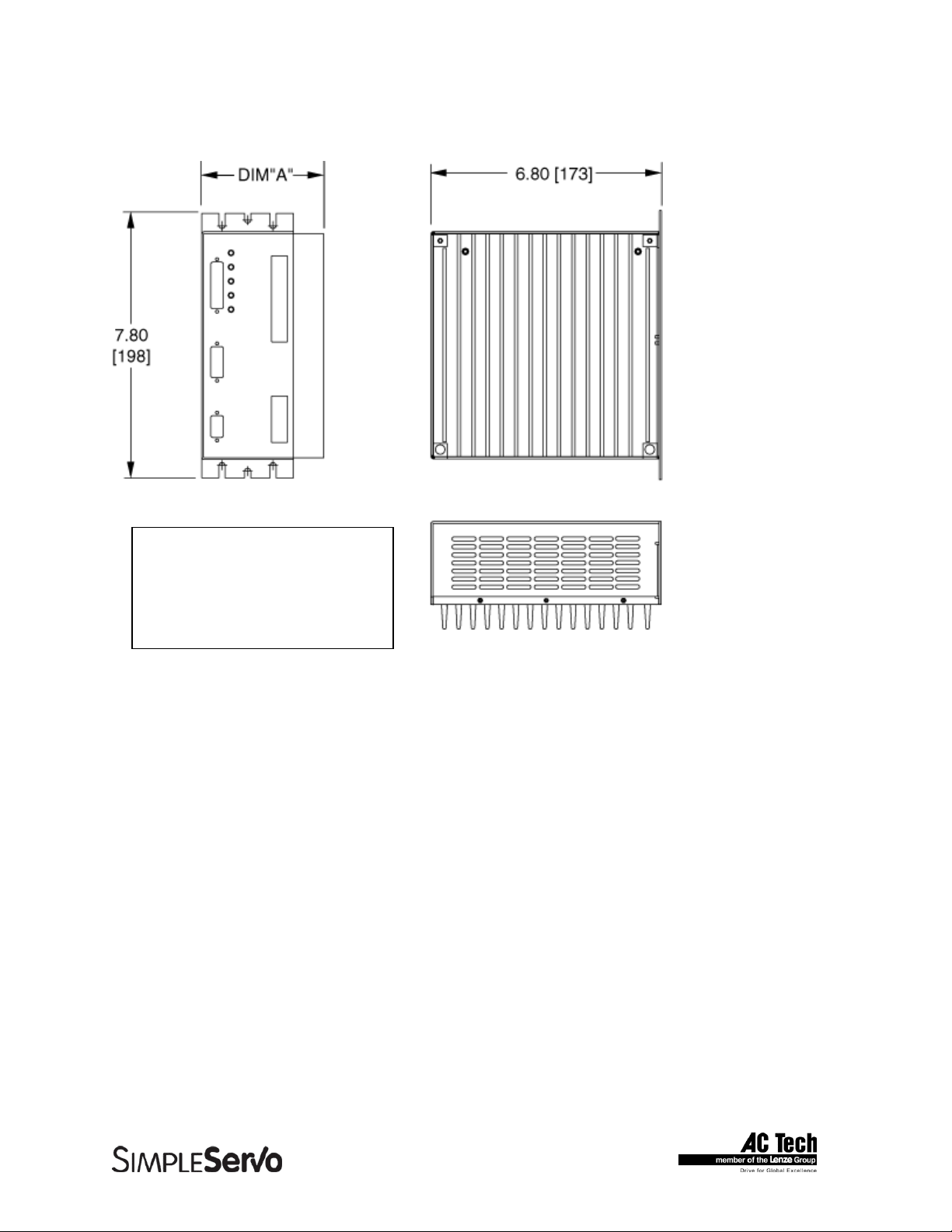
3 Dimensions
3.1 SS500 Series Dimensions
DIMENSION “A”
MODEL DIMENSION
SS504 2.60 [66] (NO HEATSINK NECESSARY)
SS508 3.80 [97]
ALL DIMENSIONS IN INCHES [MILLIMETERS]
12
Page 13
SimpleServo 500/600/i1000 User Manual Rev 3.4
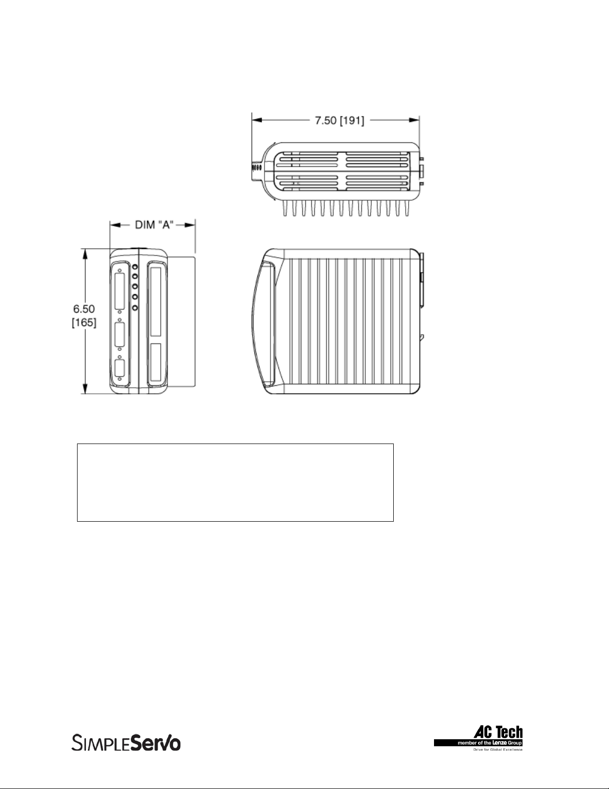
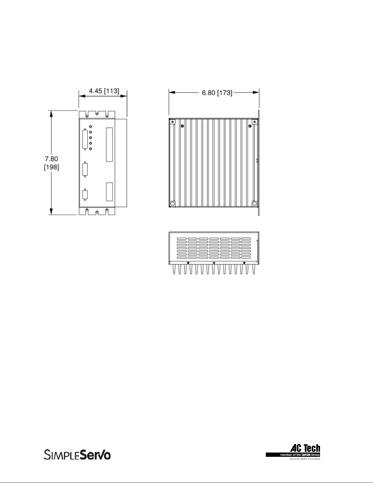
3.2 SS604/SS608/SSi1004/SSi1008 Series Dimensions
DIMENSION “A”
MODEL DIMENSION
SS604/ssi1004 2.60 [66]
SS608/ssi1008 3.54 [94]
ALL DIMENSIONS IN INCHES [MILLIMETERS]
13
Page 14
SimpleServo 500/600/i1000 User Manual Rev 3.4
3.3 SS610/SS612-3P/SSi1010/SSi1012-3P Dimensions with Heat Sink
Fan Kit Installed
ALL DIMENSIONS IN INCHES [MILLIMETERS]
14
Page 15
SimpleServo 500/600/i1000 User Manual Rev 3.4
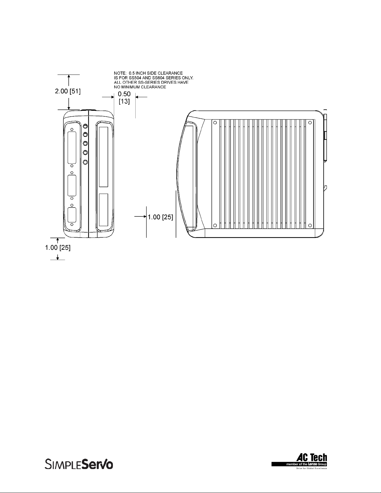
3.4 Suggested Clearance for Cooling Air Circulation (All Models)
15
Page 16

SimpleServo 500/600/i1000 User Manual Rev 3.4
4 Installation
WARNING!
• Hazard of electrical shock! Circuit potentials are at 115 VAC or 230 VAC above earth
ground. Avoid direct contact with the printed circuit board or with circuit elements to prevent
the risk of serious injury or fatality. Disconnect incoming power and wait 60 seconds before
servicing drive. Capacitors retain charge after power is removed.
• The SimpleServo must be mounted vertically for safe operation at the maximum current
rating.
• Printed circuit board components are sensitive to electrostatic fields. Avoid contact with the
printed circuit board directly. Hold the SimpleServo by the case only.
• Protect the control from dirt, filings, airborne particles, moisture, and accidental contact.
Provide sufficient room for access to the terminal block.
• Mount the control away from other heat sources. Operate within the specified ambient
operating temperature range. Additional cooling with an external fan may be recommended
in certain applications.
• Avoid excessive vibration to prevent intermittent connections
• DO NOT connect incoming power to the output motor terminals (U, V, W)! Severe damage
to the SimpleServo will result.
• Do not disconnect any of the motor leads from the SimpleServo unless power is removed or
the control is disabled. Opening any one motor lead may cause failure.
• The DIN-rail mounting tab is designed to bear only the weight of the SimpleServo and heat
sink. Make sure enough slack exists in the wire routing to ensure that the cables do not tug
or pull downward against the DIN-rail mounting tab.
16
Page 17
SimpleServo 500/600/i1000 User Manual Rev 3.4
4.1 Start Up
Step-By-Step StartUp instructions are covered in Section 9 “Operation”.
4.2 Mounting
Note: It may be necessary to add shock-absorbing “bumpers” to the back of the SS500.
1. Mount the SimpleServo vertically in the panel as shown in Figure 5.
2. Ensure that a 30 mm (1.2 inch) DIN rail is installed horizontally in the rear of the panel prior to
mounting the SS500.
3. Ensure that the upper mounting tab on the back of the SS500 is in the UP position.
4. Hook the SS500’S lower mounting tab under the DIN rail as shown in Figure 4a. The tab fit
should be snug.
5. Rotate the SS500 upward, flush against the DIN rail, ensuring that the lower mounting tab
remains engaged by the DIN rail.
6. Once the SS500 is flush against the DIN rail, push down on the mounting tab atop the drive
(Figure 4b). The mounting tab will latch onto the top of the DIN rail.
Install the bumpers as follows:
1. Peel off the adhesive cover from the clear bumper. Apply to the DIN rail tab of the SimpleServo
(the moveable tab on the rear of the control that clamps onto the top of the DIN rail).
2. Mount the drive as indicated above.
3. Peel off the adhesive cover from the black bumper. Lift the bottom of the control (while it is still
clamped to the DIN rail) to open a slightly larger air gap between the SimpleServo and the
enclosure.
4. Apply the black bumper to the back of the SimpleServo (the side facing the enclosure)
approximately one inch above the bottom. Release the drive. It should come to rest on the newly
applied black bumper.
4.3 Wiring
WARNING!
• Hazard of electrical shock! Circuit potentials are at 115 VAC or 230 VAC above earth
ground. Avoid direct contact with the printed circuit board or with circuit elements to prevent
the risk of serious injury or fatality. Disconnect incoming power and wait 60 seconds before
servicing drive. Capacitors retain charge after power is removed.
• Under no circumstances should power and control wiring be bundled together. Induced
voltage can cause unpredictable behavior in any electronic device, including motor controls.
Use 18-28 AWG wire for reference and analog signal wiring. Use 12-16 AWG wire for AC line (L1 and L2)
and motor (Phase U, V and W) wiring.
17
Page 18

SimpleServo 500/600/i1000 User Manual Rev 3.4
4.4 Shielding and grounding
4.4.1 General guidelines
AC Technology Corporation recommends the use of single-point grounding (SPG) for panel-mounted
controls. Serial grounding (a “daisy chain”) is not recommended. The SPG for all enclosures must be tied
to earth ground at the same point. The system ground and equipment grounds for all panel-mounted
enclosures must be individually connected to the SPG for that panel using 14 AWG (5.5 mm) or larger
wire. Refer to Figure 6 for wiring guidelines.
In order to minimize EMI, the chassis must be grounded to the mounting panel (Figure 6). Use 14 AWG
(1.6 mm) or larger wire to join the enclosure to earth ground. A lockwasher must be installed between the
enclosure and ground terminal. To ensure maximum contact between the terminal and enclosure, remove
paint in a minimum radius of 0.25 in (6 mm) around the screw hole of the enclosure.
AC Technology Corporation recommends the use of the special SimpleServo cables provided by AC
Technology Corporation. If you specify cables other than those provided by AC Technology Corporation,
please make sure all cables are shielded and properly grounded.
It may be necessary to earth ground the shielded cable (Figure 6). Ground the shield at the SimpleServo
end and at the motor end.
If the SimpleServo continues to pick up noise after grounding the shield, it may be necessary to add an
AC line filtering devices and/or an output filter (between drive and servo motor).
4.4.2 EMI Protection
Electromagnetic interference (EMI) is an important concern for users of digital servo control systems. EMI
will cause control systems to behave in unexpected and sometimes dangerous ways. Therefore, reducing
EMI is of primary concern not only for servo control manufacturers such as AC Technology Corporation,
but the user as well. Proper shielding, grounding and installation practices are critical to EMI reduction.
4.4.3 Enclosure
The panel in which the SimpleServo is mounted must be made of metal, and must be grounded using the
SPG method outlined above.
Proper wire routing inside the panel is critical; power and logic leads must be routed in different avenues
inside the panel .
If you use drives that output over 8 amps, you must ensure that the panel contains sufficient clearance
above and below for the cooling fan to circulate air. Refer to Figure 3 for minimum suggested cooling air
clearance.
4.5 Line filtering
In addition to EMI/RFI safeguards inherent in the SimpleServo design, external filtering may be required.
High frequency energy can be coupled between the circuits via radiation or conduction. The AC power
wiring is one of the most important paths for both types of coupling mechanisms. There are many AC line
filter manufacturers whose filters can be successively integrated. AC Tech recommends Schaffner filters
based on our test results.
18
Page 19
SimpleServo 500/600/i1000 User Manual Rev 3.4
In order to comply with EN50081-1 and EN50082-2, the following filters must be installed within 20cm of
the drive power inputs:
TABLE 1 LINE FILTER PART NUMBERS
SimpleServo P/N Schaffner AC filter P/N
SS504 FN350-8
SS508 FN350-12
SS608(-3P) FN350-12 (FN351-8
1
)
SS1008(-3P) FN350-12 (FN351-81)
SS610 FN350-20
SS1010 FN350-20
SS612-3P FN351-16
1
SS1012-3P FN351-161
1
For 3-phase (-3P) models
Line filters should be placed inside the shielded panel. Connect the filter to the incoming power lines
immediately after the safety mains and before any critical control components (Figure 6). Wire the AC line
filter as close as possible to the SimpleServo. If you add separate fuses, add them after the AC line filter.
Note
The ground connection from the filter must be wired to solid earth ground, not machine
ground.
If the end-user is using a CE-approved motor, the AC filter combined with the recommended SimpleServo
motor and encoder cables, is all that is necessary to meet the EMC directives listed herein. The end user
must use the comparable filter (see table above), to comply with CE specifications. The OEM may choose
to provide alternative filtering that encompasses the SimpleServo and other electronics within the same
panel. The OEM has this liberty because CE is a machinery directive.
4.6 Heat sinking
SimpleServos contain sufficient heat sinking in their basic configuration. There is no need for additional
heat sinking. However, drives that output more than 8 amps incorporate a heat sink cooling fan; you must
ensure that there is sufficient clearance for the cooling fan to circulate air (Figure 3). As a minimum, you
must allow an air gap of 1 inch above and below the drive.
4.7 Line fusing
External line fuses must be installed on all SimpleServos. Connect the external line fuse in series with the
AC line voltage input. Table 3 lists the recommended line fuse sizes. Use fast acting fuses rated for 250
VAC or higher, and approximately 200% of the maximum phase current.
TABLE 2 RECOMMENDED LINE FUSE SIZES
Model Number Line Fuse Size (AC Amps)
SSX04
SSX08
SSX12
15
25
30
19
Page 20
SimpleServo 500/600/i1000 User Manual Rev 3.4
5 SimpleServo Connections
The standard SimpleServo control contains five connectors: two quick-connect terminal blocks and three
subminiature type “D” connectors. These connectors provide power, communications and external
feedback to the motor, SimpleServo control, and host controller (Figure 8). Prefabricated cable
assemblies may be purchased from AC Technology Corporation to facilitate wiring the control, motor and
host computer. Contact your SimpleServo Sales Representative for assistance.
5.1 External Connectors
5.1.1 TB501 - Power, Motor, and Fuse Connections
TB501 is an 8-pin quick-connect terminal block used for motor, power and fuse connections. Refer to
Table 3 for connector pin assignments. Where referenced in the table below, refer to Connector Wiring
Notes for more information.
WARNING!
• Hazard of electrical shock! Circuit potentials are at 115 VAC or 230 VAC above earth
ground. Avoid direct contact with the printed circuit board or with circuit elements to prevent
the risk of serious injury or fatality. Disconnect incoming power and wait 60 seconds before
servicing drive. Capacitors retain charge after power is removed.
• DO NOT connect incoming power to the output motor terminals (U, V, W)! Severe damage
to the SimpleServo will result.
All conductors must be enclosed in one shield and jacket around them. The shield on the amplifier end
must be terminated at TB501 pin 6 (chassis ground); the other end should be properly terminated at the
motor shield. To satisfy CE requirements, AC Technology Corporation recommends that you purchase
SimpleServo cables for both the motor and AC line. Contact your SimpleServo representative for
assistance.
Wire size
If current draw is less than 8 amps: 16 AWG (1.0 mm) or 14 AWG (1.6 mm)
If current draw is greater than 8 amps but less than 12 amps: 14 AWG (1.6 mm) or 12 AWG (2.6 mm)
If current draw is greater than 12 amps: 12 AWG (2.6 mm)
TABLE 3 TB501 PIN ASSIGNMENTS (single phase models)
Terminal Block Pin # Name Function
1 W (T) Motor Power Out
2 V (S) Motor Power Out
3 U (R) Motor Power Out
4 DUMP+ Dump resistor out
5 DUMP- Dump resistor out
6 GND Chassis ground
7 L1 AC Power In
8 L2 AC Power In
20
Page 21

SimpleServo 500/600/i1000 User Manual Rev 3.4
TABLE 4 TB501 PIN ASSIGNMENTS (3 phase models)
Terminal Block Pin # Name Function
1 W (T) Motor Power Out
2 V (S) Motor Power Out
3 U (R) Motor Power Out
4 DUMP+ Dump resistor out
5 DUMP- Dump resistor out
6 GND Chassis ground
7 L1 AC Power In
8 L2 AC Power In
9 L3 AC Power In
5.1.2 TB502 - Analog/Digital I/O Terminal Block
TB502 is a 15-pin quick-connect terminal block used for analog and digital I/O functions in standalone
mode.
TABLE 5 TB502 PIN ASSIGNMENTS (all models except SSi10XX)
Terminal Block Pin# Name Function
1 -REF -10V (5mA)
2 IN- Positive (+) of analog signal input
3 IN+ Negative (-) of analog signal input
4 +REF +10V (5mA)
5 AGND Analog ground (attach shield from signal source here)
6 MA+/Step+ Step+ (or master encoder channel A+) input1
7 MA-/Step- Step- (or master encoder channel A-) input1
8 MB+/Dir+ DIR+ (or master encoder channel B+) input
9 MB-/Dir- DIR- (or master encoder channel B-) input
10 Analog Output Programmable analog output
11 AUX INPUT Programmable digital input
12 EN Enable Input2
13 OUT_RDY Ready output O.C.
14 OUT_AUX Programmable Output O.C.
15 GND Logic common
21
Page 22

SimpleServo 500/600/i1000 User Manual Rev 3.4
TABLE 6 TB502 PIN ASSIGNMENTS (SSi10XX only)
Terminal Block Pin # Name Function
1 -Vcc -Vcc (5mA)
2 REF- Negative reference input (differential)
3 REF+ Positive reference input (differential)
4 +Vcc -Vcc (5mA)
5 AGND Analog ground (attach shield from signal source here)
6 SPARE
7 SPARE
8 SPARE
9 SPARE
10 Analog output Programmable analog output
11 SPARE
12 SPARE
13 SPARE
14 SPARE
15 GND Logic common
22
Page 23
SimpleServo 500/600/i1000 User Manual Rev 3.4
5.1.3 Encoder feedback
An encoder needs to have power supplied to it. Both front-end controllers and the SimpleServo each
have a +5 VDC supply voltage that may be used to power the encoder. The SimpleServo contains patentpending automated switching circuitry, which will power the encoder from a front-end controller if it is
present (through the ENC+ pin). If no supply voltage is present at the ENC+ pin, the SimpleServo will
switch its internal power (+5 VDC supply) to the encoder.
WARNING!
Use only +5 VDC encoders. Do not connect any other type of encoder to the SimpleServo
reference voltage terminals. When using a front-end controller, it is critical that the +5 VDC
supply on the front-end controller NOT be connected to the +5 VDC supply on the
SimpleServo, as this will result in damage to the SimpleServo.
Note
• SimpleServo inputs are compatible with single-ended or open-collector type of hall sensors.
If you have these type of hall sensors just connect them to “HA+”, “HB+”, “HC+” and leave
“HA-,HB-,HC-“ inputs unconnected. You don’t need to supply pull-up resistors in case the
hall sensors are open-collector. Necessary pull-up circuits are already provided inside
SimpleServo amplifier.
• Encoder connections must be full differential. SimpleServo doesn’t support single-ended or
open-collector type outputs for encoder.
• An encoder resolution of 2000 PPR or higher is recommended for optimum performance.
5.1.4 TB504 - Motor Feedback Input
TB504 is a 15-pin DB connector that contains connections for Hall effect sensors and encoder feedback.
Refer to Table 5 for connector pin assignments. Encoder inputs on TB504 have 26LS32 or compatible
differential receivers for increased noise immunity. Inputs have all necessary filtering and line balancing
components so no external noise suppression networks are needed.
All conductors must be enclosed in one shield and jacket around them. AC Technology Corporation
recommends that each and every pair (for example, EA+ and EA-) be twisted. In order to satisfy CE
requirements, use of an OEM cable is recommended. Contact your SimpleServo representative for
assistance.
The SimpleServo buffers encoder feedback through TB504 to TB506. Encoder channel A on TB506, for
example, is buffered channel A pin of TB504 inside the SimpleServo. The Hall sensors from the motor
must be wired to the 15-pin connector.
23
Page 24

SimpleServo 500/600/i1000 User Manual Rev 3.4
TABLE 7 TB504 PIN ASSIGNMENTS
"D"-Sub Pin # Name Function3
1 EA+ Encoder Channel A
2 EA- Encoder Channel A Not4
3 EB+ Encoder Channel B
4 EB- Encoder Channel B Not
5 EZ+ Encoder Channel Z
6 EZ- Encoder Channel Z Not
7 GND Drive Common/Encoder Ground
8 SHLD Shield
9 PWR Encoder supply (+5VDC)
10 HA- Hall Sensor A-
11 HA+ Hall Sensor A+
12 HB+ Hall Sensor B+
13 HC+ Hall Sensor C+
14 HB- Hall Sensor B-
15 HC- Hall Sensor C-
24
Page 25
SimpleServo 500/600/i1000 User Manual Rev 3.4
5.1.5 TB505 - Serial Communications Port
TB505 is a 9-pin D-sub connector that is used to communicate with a host computer via standard RS232
interface. This port is present on all SimpleServo drives. All levels must be RS-232C compliant.
TB505 Pin Assignments (all models)
"D"-Sub Pin # Name Function
1 Reserved
2 TX RS232 TX
3 RX RS232 RX
4 Reserved
5 GND Common
6 Reserved
7 Reserved
8 Reserved
9 Reserved
WARNING!
Do not make any connection to Reserved pins!
Note
If you purchase serial cables from a third party, you must use a pass-through cable, not NullModem (not crossover).
25
Page 26

SimpleServo 500/600/i1000 User Manual Rev 3.4
5.1.6 TB506 - Controller Interface (SS500/600 drives)
TB506 is a 25-pin DB connector for interfacing to front-end controllers. It is strongly recommended that
you use OEM cables to aid in satisfying CE requirements. Contact your SimpleServo representative for
assistance.
TABLE 8 TB506 PIN ASSIGNMENTS
"D"-Sub Pin # Name Function3
1 EA+ Encoder Channel A
2 EA- Encoder Channel A Not4
3 EB+ Encoder Channel B
4 EB- Encoder Channel B Not
5 EZ+ Encoder Channel Z
6 EZ- Encoder Channel Z Not
7 GND Drive Common
8 SHLD Shield
9 ENC+ Positive Terminal of Encoder Power (+)5
10 N/C Spare
11 MA+/Step+ Master Encoder A+ / Step input+1
12 MA-/Step- Master Encoder A- / Step input-1
13 MB+/Dir+ Master Encoder B+ / Direction input +
14 MB-/Dir- Master Encoder B- / Direction input -
15 READY-C Output Ready OC. Collector
16 READY-E Output Ready OC. Emitter
17 ENABLE+ Enable Input +2
18 ENABLE- Enable Input -2
19 AUX-C Programmable output OC. Collector
20 AUX-E Programmable output OC Emitter
21 EXTPOWER +5 V (20mA max)
22 GND Drive Common
23 IN+ Positive (+) of Analog signal input
24 IN - Negative (-) of Analog signal input
25 Analog Ground Reference Signal Ground/Analog Shield
26
Page 27

SimpleServo 500/600/i1000 User Manual Rev 3.4
5.1.7 TB506 - Encoder repeat and analog input connections (SSi1000 drives)
TB506 is a 25-pin DB connector that includes buffered motor encoder repeat and analog input
connections.
TABLE 9 TB506 PIN ASSIGNMENTS
"D"-Sub Pin # Name Function3
1 EA+ Encoder Channel A
2 EA- Encoder Channel A Not4
3 EB+ Encoder Channel B
4 EB- Encoder Channel B Not
5 EZ+ Encoder Channel Z
6 EZ- Encoder Channel Z Not
7 GND Drive Common
8 SHLD Shield
9 SPARE
10 SPARE
11 SPARE
12 SPARE
13 SPARE
14 SPARE
15 SPARE
16 SPARE
17 SPARE
18 SPARE
19 SPARE
20 SPARE
21 SPARE
22 GND Logic Common
23 IN+ Positive (+) of Analog signal input
24 IN - Negative (-) of Analog signal input
25 Analog Ground Reference Signal Ground/Analog Shield
27
Page 28

SimpleServo 500/600/i1000 User Manual Rev 3.4
5.1.8 Connectors and Wiring Notes
Note 1
An external pulse train signal (for “step”) supplied by an external device, such as a PLC or stepper
indexer, can control the speed and position of the servomotor. The speed of the motor is controlled by the
frequency of the step signal, while the number of pulses that are supplied to the SimpleServo determines
the position of the servomotor. “DIR” input controls direction of the motion.
Note 2 (SS500/600 drives only)
The enable (EN) pin, TB502 pin 12 or TB506 pin 17/18, must be wired to one of the output terminals on
the front-end controller, i.e., if the controller is present, it must supervise the enable function on the
SimpleServo. The SimpleServo will accept open-collector outputs for use as a switch, TTL or CMOS
outputs (5V) programmed for active low operation.
Note 3
Each of the encoder output pins on TB506 is buffered pass-through. The encoder channel A pin on
TB504, for example, is buffered and routed to the encoder channel A pin on TB506 inside the
SimpleServo. If you require encoder information, wire your controller to TB506. The encoder and Hall
sensor feedback from the motor must be wired to the 15-pin Type D receptacle (connector) through the
feedback cable.
Note 4
The complement of A is sometimes written as not A. The B, C and Z encoder channels are annotated in a
similar fashion.
Note 5
WARNING!
Use only +5 VDC encoders. Do not connect any other type of encoder to the SimpleServo
reference voltage terminals. When using a front-end controller, it is critical that the +5 VDC
supply on the front-end controller NOT be connected to the +5 VDC supply on the
SimpleServo, as this will result in damage to the SimpleServo.
The encoder needs to have power supplied to it. A front-end controller, as well as the SimpleServo, has a
+5 VDC supply voltage that may be used to power the encoder. The SimpleServo contains patentpending automated switching circuitry which will power the encoder from a front-end controller if it is
present (through the ENC+ pin). If no supply voltage is present at the ENC+ pin, the SimpleServo will
switch its internal power (+5 VDC supply) to the encoder.
28
Page 29

SimpleServo 500/600/i1000 User Manual Rev 3.4
5.2 Digital I/O details (SS500/600 drives)
5.2.1 Step and Direction/ Master Encoder Inputs
TB506-11,12,13,14 and TB502-6,7,8,9
You can connect a master encoder with quadrature outputs or a step and direction pair of signals to
control position in step/direction operating mode. These inputs are optically isolated from the rest of
the drive circuits and from each other. Both inputs can operate from any voltage source in the range of
5 to 24 VDC and do not require additional series resistors for normal operation. See figure below.
Master encoder/step and direction input circuit.
You can connect a single ended or differential signal to the inputs. You can also connect sinking or
sourcing outputs to these inputs. See application note in Section 12 of this manual for the connection
guidelines. The function of these inputs “Master Encoder” or “Step and Direction” is software
selectable. Use MotionView set up program to choose desirable function.
5.2.2 Digital outputs
There are two digital outputs “READY” and “OUT AUX” available in different output configurations.
On TB506:
“READY”(TB506-15, 16) “AUX-C and AUX-E” (TB506-19, 20).
Outputs are fully isolated from the rest of the drive circuits (“dry contact”). See figure below for its
electrical diagram.
29
Page 30

SimpleServo 500/600/i1000 User Manual Rev 3.4
On TB502:
“AUX” output
• Zero speed
• In speed window
• Current limit
• Run Time Fault
“OUT_RDY” (TB502-13), “OUT_AUX” (TB502-14).
Functions the same as “READY” and “AUX” have open-collector sinking outputs (sinking only)
referenced to drive logic common. See figure below for the electrical diagram.
Both versions of these outputs (On TB506 and TB502) have the same logic.
“READY” output
Activated when the drive is ready and enabled. It is reset to an inactive state when the drive is
disabled, not operational or any fault is detected.
Programmable output. Activated when any of the selected conditions are true. These
conditions are software selectable. Use MotionView to select the condition assigned to this
programmable output. Only one condition at a time can be selected for output. Possible
choices are:
5.2.3 Digital inputs
“ENABLE+ & ENABLE-” (TB506-17, 18).
Optically isolated input. Compatible with 5 -24V voltage source or open-collector sinking
output. For connection guidelines, refer to the application note in Section 12. See figure
below for electrical diagram.
30
Page 31

SimpleServo 500/600/i1000 User Manual Rev 3.4
AUX INPUT (TB502-11), “EN” (TB502-12)
“EN” Functions same as “ENABLE+ / ENABLE-”
This is a single-ended input, compatible with 5V TTL, open-collector sinking output, and switch
or relay contacts. The input is referenced to drive logic common. These inputs are active low,
i.e., connecting it to drive logic common or supplying logic “0” referenced to drive logic
common activates this input. For connection guidelines see application note in Section 12.
See figure below for electrical diagram.
“EN”, “ENABLE+ ENABLE- ”
Drive enable input. Activating this input enables the drive.
“AUX INPUT”
Programmable input: Function of this input is software selectable. Use MotionView program to
select the function for this input. Possible choices are:
• External fault
• Stop
• Reverse
31
Page 32

SimpleServo 500/600/i1000 User Manual Rev 3.4
5.3 Digital I/O details (SSi1000 drives)
SSi10XX indexing drives have 25-pin D-sub digital I/O connector. Digital I/O supplement on these
drives consists of 12 inputs and 5 outputs. All I/O optically isolated from rest of the drive’s circuitry.
5.3.1 Digital inputs
SSi drives have 12 digital inputs which are separated on 4 groups. Each group has its own common
for inputs in the group. All inputs are optically isolated and suitable for 5–24 VDC input control voltage.
Some of the inputs can be configured to carry out special functions. Refer to Table 7 for digital inputs
function reference. All inputs have same electrical characteristics and the same input circuitry
arrangements.
5.3.1.1 Special functions
Inputs C1,C2. Master Encoder connections
Inputs C1 and C2 are suitable for Master Encoder connection for Gear Mode usage. Inputs C1 and C2
are capable of handling signals with of up to 2 MHz rate. Refer to Programmer’s Manual for details.
Inputs A1,A2. Limit switches connection.
These inputs can be used for Limit switches connections. These two inputs will perform different
actions upon activation if programmed to do so. When programmed for <Not assigned> they function
as normal inputs. Refer to Section 7.3.2 for details.
Input A3. Enable
A3 input can be programmed for ENABLE function. When this input is programmed for ENABLE
function it must be active before ENABLE statement is issued otherwise fault will be generated. If this
input gets deactivated while drive is enabled drive will stop and generate fault. When input is not
programmed for a special function, it functions as a normal input.
Input C3. Registartion sensor input.
This input can be used for registration sensor connection. Upon activation of the input, current actual
position is recorded and is available for User Program. This input also used in all registration move
commands. Refer to Programmer’s Manual for details.
5.3.2 Digital outputs
SSi drives have 5 digital outputs numbered 1 to 5. Outputs 1 - 4 can be configured as general-purpose
outputs, or can be configured for special functions (selection made via MotionView program in I/O
folder Section 7.3.1 of this manual). Output #5 is dedicated as “READY”, which is ON when SSi is
enabled and OFF when SSi is disabled or at fault. Output #5 is not accessible via User Program or
Host Interface.
All outputs are optically isolated from SSi circuitry and each other and are open collector type. They
have 30mA load capability. Both Collector and Emitter of each output are available for customer
connection.
32
Page 33

SimpleServo 500/600/i1000 User Manual Rev 3.4
TABLE 10 TB507 PIN ASSIGNMENTS
Pin
number
Function Aux function Pin
number
Function Aux function
1 Input A1 Left limit 14 Output 1 C
2 Input A2 Right limit 15 Output 1 E
3 Input A3 Enable 16 Output 2 C
4 Input A4 17 Output 2 E
5 Common for A
18 Output 3 C
section
6 Input B1 19 Output 3 E
7 Input B2 20 Output 4 C
8 Input B3 21 Output 4 E
9 Input B4 22 Output 5 C Ready C
10 Common for B
23 Output 5 E Ready E
section
11 Common for C
24 Input C4
section
12 Input C2 ME B 25 Input C3 Registration
13 Input C1 ME A
33
Page 34

SimpleServo 500/600/i1000 User Manual Rev 3.4
Inputs A1-A4 COM
A1
A2
A3
A4
Inputs B1-B4 COM
B1
B2
B3
B4
Inputs C1-C4 COM
1
2
3
4
5
6
7
8 9
1
2
3
4
5
6
7
8 9
16
15
14
13
12
11
10
SSi drive's
circuitry
16
15
14
13
12
11
10
1
2
3
4
5
6
7
8 9
1
2 3
16
15
14
13
12
11
10
4
OUT1+
OUT1-
OUT2+
OUT2-
OUT3+
OUT3-
OUT4+
OUT4-
READY+
READY-
C3
C3
C3
C4
1
2
3
4 5
1
2
3
4 5
8
7
6
8
7
6
U3
SSi drives I/O arrangements
34
Page 35

SimpleServo 500/600/i1000 User Manual Rev 3.4
5.4 Analog I/O details
5.4.1 Analog reference input
IN+, IN- (TB506-23, 24 or TB502-2,3)
Analog differential input. This input will accept +/-10V single-ended voltage on IN+ or IN- input or
+/-5V differential voltage between IN+ and IN-. Both connections must be referenced to Analog
Common (TB506-25 or TB502-5) of the drive. This input is used to control speed or torque of the
motor in velocity or torque mode (SS500/600 only).The total reference voltage as seen by the drive is
the voltage difference between IN+ and IN-. If used in single-ended mode one of the inputs must be
connected to voltage source while the other one must be connected to Analog Common. If used in
differential mode, the voltage source is connected across IN+ and IN- inputs and driving circuit
common (if any) needs to be connected to drive Analog Common terminal.
Reference as seen by drive:
Vref = (VIN+) - (VIN-)
Note
In SSi1000 drives, Vref is available by reading System Variable “AIN”.
5.4.2 Analog output
Analog out. (TB502-10)
Analog output is single ended –10/+10V span signal which can represent different quantities of the
drive (SS500/600 only). For SS500/600 drives MotionView SetUp program can be used to select
signal source for the analog output as well as its scaling. SSi1000 indexing drives can set analog
output directly from User program (Sysytem Variable “AOUT”) or via Host Interface command. Load
capability of that output is 10mA.
5.5 Communication interfaces (SS500/600 drives)
Drives are equipped with RS232 communication interface. Communication speed is fixed at 38,400
baud.
5.6 Communication interfaces (SSi1000 drives)
In addition to standard RS232 interface SSi indexing drives have RS485 and Ethernet communication
interfaces. Communication speed for RS232/485 can be 115200 or 38400 baud and DIP-SWITCH
DS501 #6 selectable.
5.6.1 RS232 interface
This interface is available on SSi drives for communication with Host computer. The SSi RS232 is
addressable, with the address set by DIP-SWITCH DS501. See “RS485 interface” paragraph below to
see how address should be set. The SSi RS232 has a unique re-transmitting feature. If you send
commands using RS232 interface to the drive with a different address, the drive will retransmit this
command to the RS485 network so the other drive might pick it up. This allows the possibility of
connecting a network of SSi drives to a Host computer via RS232 on one of the drives in the network.
There is no special adjustments or setups needed to start using this feature.
35
Page 36

SimpleServo 500/600/i1000 User Manual Rev 3.4
5.6.2 RS485 interface
RS485 interface is available at the 4 pins screw terminal connector TB508. Up to 32 drives can be
daisy chained by connecting their “+” and “-“ terminals using twisted pair wire. Connect termination
resistor between “+” and “-“ terminals of the last drive in network. See figure below for connection.
TABLE 11 TB508 RS485 CONNECTOR
PIN # Function
1 RS485 Data +
2 RS485 Data +
3 RS485 Data 4 RS485 Data -
RS485 Network connection. Use twisted pair wire with optional shield. Connect shield to the
earth ground (optional).
Network Master (Computer or PLC)
RS485 Data +
RS485 Data -
120
Last Drive in the network
terminated with resistor
Additional Drives (Up to 32 total)
36
Page 37

SimpleServo 500/600/i1000 User Manual Rev 3.4
DIP-SWITCH DS501 has its first 5 switches for address assignment and switch #6 for baud rate
selection. Two speeds are possible: 38,400 and 115,200 baud. As mentioned previously, up to 32
drives can be connected to a single network. Each drive on the network has to have its own unique
address set via DIP-SWITCH. Pulling switch UP sets it ON and pulling switch DOWN sets it OFF. The
drive address will be a sum of all ON switch values. For example, if switches 1,2, and 5 are ON and
the rest of the switches are OFF, the resulting address will be 1(#1)+2(#2)+16(#5) = 19.
TABLE 12 DIP-SWITCH DS501
Dip-switch # Value
1 1
2 2
3 4
4 8
5 16
6 OFF = 115200, ON = 38400 baud
To assign an address of 10, the sum of the switch values must be equivalent to 10. In this case,
switches 2 and 4 would need to be set to ON (2 + 8 =10).
Diagnostic LED. (green)
There are two LEDs near RS485 connector. Green LED lights up when data is sent to or from drive
over the RS485 interface. Refer to Section 9.1.2 for more information on the LEDs.
5.6.3 Ethernet interface.
SSi drives support standard 10/100 Ethernet connection via modular RJ-45 jack and CAT-5 standard
twisted pair network cable used in computer equipment. The RJ-45 socket has two integrated LEDs
showing network status. Green LED lights up when physical connection is present and yellow LED
lights up when SSi sends or receives data over the Ethernet.
SSi drives support both manual and automatic IP parameters assignment. Automatic (DHCP)
assignment of IP properties is possible if there is a DHCP server on the network. This is the default
setting. You can quickly connect drive(s) to floor/corporate network and configure it for further
operation. In manual mode you need to supply the IP address, Subnet mask, and Default gateway.
Default gateway address is needed only if drives are located on different subnets. If drives are on the
same network and there is no gateway supply to this field address of the host computer or address on
the same subnet but not used by any of the devices.
37
Page 38

SimpleServo 500/600/i1000 User Manual Rev 3.4
5.7 Motor Selection
SimpleServo drives are compatible with many servo motors, both AC Technology Corporation motors
and motors from the other manufacturers. We have tested many motors with the SimpleServo and put
their parameters in a database for customer convenience. If you opted for the motor which is in the
database you do not need to provide any motor data to set up motor for the use. However if your
motor is not in the database you can still use it but need to provide some electrical and mechanical
data to make a custom motor profile. The auto-phasing feature of SimpleServo allows you to correctly
determine relation between phase voltage and hall sensor signals, eliminating the need to use a multichannel oscilloscope.
5.7.1 Setting Up motor
MotionView Motor Group on the left tree shows currently selected motor. You can click “CLICK HERE
TO CHANGE” to view selected motor parameters or select new motor.
MotionView’s <Motor Group> folder and its contents
Note
If drive is ENABLED, a new motor cannot be set. You can only set a new motor when the
drive is DISABLED.
38
Page 39

SimpleServo 500/600/i1000 User Manual Rev 3.4
To View selected motor parameters or make a new motor selection:
• Click “CLICK HERE TO CHANGE”. Selection dialog opens. (See figure above). If you are
just viewing motor parameters click Cancel on Motor Parameters dialog when done. This
will dismiss dialog and return back to MotionView.
• Select motor Vendor from the right list box and desired motor from the left list box.
• If you want to use custom motor instead of available motors from supplied database then
go to Selecting custom motor topic below.
• Finally click OK button to dismiss dialog and return to Motion View main program.
5.8 Using custom motor
• You can load custom motor from file or you can create new custom motor.
• To create custom motor click Create custom and follow instruction in topic Setting custom
motor parameters below.
• To load custom motor click <Open custom> button then select motor file and click OK to
dismiss file dialog.
• Click OK to return to Motion View program or Cancel to abandon changes.
5.8.1 Setting custom motor parameters
WARNING!
Use extreme caution when entering custom parameters! Incorrect settings may cause
damage to the drive or motor! If you are unsure of the settings, refer to the materials that
were distributed with your motor, or contact the motor manufacturer for assistance.
1. Enter custom motor data in the motor parameters dialog fields. Complete all sections of
dialog: Electrical, Mechanical, Feedback. See Section 6.8.3 for explanation of motor
parameters and how to enter them.
Note
If you don’t know, or are unsure of, the motor halls order and encoder channels A and B
relationship, leave “B leads A for CW”, “Halls order” and “inverted” fields as they are. You
can execute autophasing (see below) to set them correctly.
2. Enter motor model text in Motor Model edit box. Do not enter Motor ID. For custom motors it is
0 and will be assigned automatically when you save motor data to file.
3. Click Save to File button and enter filename without extension. Default extension .cmt will be
given when you click OK on file dialog box.
Note
Saving the file is necessary even if you are going to use the autophasing feature and still
don’t know all of the final parameters. After autophasing is completed you will have a
chance to save the corrected motor file again before loading it to memory.
4. Click OK to dismiss Motor Parameters dialog.
5. MotionView will ask if you want autophase your custom motor. If you answer “No” motor data
will be loaded immediately to the drive’s memory. If you answer “Yes” motor dialog will be
dismissed and drive will start autophasing sequence. Refer to topic below for autophasing
information.
6. If you answered “Yes” when prompted for autophasing after autophasing is completed you will
be returned to the same motor selection dialog box. At this time fields “B leads A for CW” ,
“Halls order” and “inverted” fields will be assigned correct values. Click “Save File” to save
custom motor file and then “OK” to dismiss dialog and load data to drive memory.
39
Page 40

SimpleServo 500/600/i1000 User Manual Rev 3.4
5.8.2 Autophasing
Autophasing is the feature of the SimpleServo drives that helps determine some important motor
parameters when using a motor which is not in the MotionView database. Autophasing will determine
Hall order sequence, Hall sensor polarity and encoder channel relationship (B leads A or A leads B for
CW rotation).
To perform autophasing:
1. Complete steps in Section 5.8.1 “Setting custom motor parameters” above. If the motor file
you are trying to autophase already exists on your hard drive, simply load it per “Selecting
custom motor” section above.
2. Make sure that the motor’s shaft is not connected to any mechanical load and can freely
rotate.
3. Make sure that the drive is disabled.
4. Do not edit field “Hall order” and check boxes “inverted”, ”B leads A for CW” because their
values are ignored for autophasing.
5. Click OK to dismiss motor selection dialog. MotionView responds with the question “Do you
want to perform autophasing?”
6. Click OK. Safety reminder dialog appears. Click “Proceed” and wait until autophasing is
completed.
7. If there was a problem with motor connection and/or hall sensor connection, MotionView will
respond with an error message. Correct wiring problem(s) and repeat steps 1 – 6.
8. If autophasing is completed with no error then MotionView will return to motor dialog box and
parameter fields “Hall order” and check boxes “inverted”, ”B leads A for CW” will be filled with
correct values.
9. Click “Save File” to save motor file to disk (you can use the same filename as you use to save
initial data in step 1) and click OK to send motor data to the drive.
5.8.3 Custom Motor Data Entry
Motor Parameters dialog has three sections (frames) dividing motor parameters on groups:, Electrical
constants, Mechanical constants, and Feedback. When creating custom motor entry you must supply
all parameters listed in these sections. All entries are mandatory except inertia (Jm) parameter. You
may enter 0 if you are not sure of a value.
Electrical constants.
• Motor Torque Constant (Kt).
Be careful with the units! This must be set in Newton-Meters per Amp RMS (N-m/A). The torque
constant for many motors will be given in different English units such as pound-inches per Amp
(lb-in/A) or ounce-inches per Amp (oz-in/A). You will need to convert these English units to metric.
To convert lb-in/A to N-m/A, multiply by 0.1130.
To convert oz-in/A to N-m/A, multiply by 0.00706.
Example: Suppose we are given a Kt = 0.69 lb-in/A. Multiplying by the appropriate
conversion factor yields:
Kt = (0.69 lb-in/A)(0.1130) = 0.0780 N-m/A (therefore the entry for Kt would be 0.078)
Note
Round the calculated result to 3 significant places.
40
Page 41

SimpleServo 500/600/i1000 User Manual Rev 3.4
• Motor Voltage Constant (Ke).
This must be set in Volts per thousand RPM (V/kRPM). The motor voltage constant will typically
be between Ke = 1V/kRPM and Ke = 70 V/kRPM. This entry should be made to 3 significant
places. Include the decimal places if the number is given as a whole number (for example, if Ke is
given as 34 V/kRPM, then enter 34.0). The program expects to enter Ke voltage constant for
Phase-Phase voltage RMS value. If you have Ke for peak sine wave then multiply by 0.707 to get
correct Ke RMS value.
• Phase to phase winding Resistance (R) in Ohms ( Ω).
This is also listed as the terminal resistance (Rt). The phase-to-phase winding Resistance will
typically be between R = 0.5 Ohms and R = 200 Ohms.
• Phase to phase winding Inductance (L).
This must be set in milliHenries (mH). The phase-to-phase winding Inductance will typically be
between L = 0.5 mH and L = 150.0 mH.
Note
If the units for the phase-to-phase winding Inductance (L) are given in microHenries (µH),
then multiply by 1000 to get mH.
• Nominal phase current (RMS Amps) Maximum continuous phase current rating (Imax) in Amps
RMS. Do not use the peak current rating.
Note
Sometimes the phase current rating will not be given. The equation below may be used to
obtain the maximum continuous phase-to-phase winding current from other variables.
Imax= Continuous Stall Torque / Motor Torque Constant (Kt)
The same force x distance units must be used in the numerator and denominator in the equation
above. If T (torque) is expressed in units of pound-inches (lb-in) then, Kt must be expressed in pundinches per Amp (lb-in/A). Likewise, if T is expressed in units of Newton-meters (N-m), then units for Kt
must be expressed in Newton-meters per Amp (N-m/A).
Example: Suppose that the maximum continuous phase to phase winding current (Imax) is
not given. Instead, we look up and obtain the following:
Continuous stall torque T = 3.0 lb-in
Motor torque constant Kt = 0.69 lb-in/A
Dividing, we obtain:
Imax = 3.0 lb-in / 0.69 lb-in/A =4.35 (A)
Our entry for Imax would be 4.35. Note that the pound-inch (lb-in) units cancelled in the
equation above leaving only Amps (A). We would have to use another conversion factor if the
numerator and denominator had different force x distance units.
• Nominal Bus Voltage (V
BUS
).
If the motor nominal terminal voltage is 200 - 240VAC phase to phase, enter 325(V).
If the motor nominal voltage is below 200VAC enter 165 (V).
This value is initial (seed) voltage for drive and correct voltage will be calculated dynamically
depending on the drive’s incoming voltage value.
41
Page 42

SimpleServo 500/600/i1000 User Manual Rev 3.4
Note
The motors that are entered in this database should have Nominal Bus Voltage between
90 V and 340V. Do not enter motors with terminal voltages below 90 V.
Mechanical constants tab.
• Rotor Moment of Inertia (Jm).
Must be set for moment of inertia (not inertia!) in kilogram-meters squared (kg-m
moment of inertia for many motors will be given in English units such as pound-inches squared
2
) or ounce-inches squared (oz-in2). These must be converted to metric as follows:
(lb-in
To convert lb-in
2
to kg-m2 , multiply by 2.93x10⁻⁴
2
). The rotor
To convert oz-in2 to kg-m2 , multiply by 1.83x10⁻⁵
To convert lb-in-sec2 to kg-m2 , multiply by 0.113
To convert oz-in-sec2 to kg-m2 , multiply by 7.06x10⁻³
Note
Round the calculated result to 3 significant places.
Maximum Motor Speed in RPM.
This is also listed as Speed @ V
(motor speed at the terminal voltage rating). The maximum
t
motor speed will typically be a round even value between 1000 and 6000 RPM.
Feedback tab.
• Number of Poles.
This is a positive integer number represents number of motor’s poles which is normally 2, 4,6 or 8.
Encoder Line Count
The Encoders for servomotors normally have Line Counts of 1000, 1024, 2000, or 2048. The
Encoder Line Count must be a positive integer.
Z Position. Enter 0 (zero)
Zero marker pulse position. This field is reserved for backward compatibility. All SimpleServo
drives determine actual marker pulse position automatically.
• Halls Order.
Each hall signal is in phase with one of the three phase-phase voltages from motor winding. Hall
order number defines which hall sensor match to what phase-phase voltage. Motor phases are
usually called R-S-T or U-V-W or A-B-C. Phase-Phase voltages are called Vrs, Vst, Vtr. Halls are
usually called HALL-A, HALL-B, HALL-C or just Halls 1, 2, 3. A motor’s phase diagram is supplied
by motor vendor and usually can be found in motor datasheet or making a request to motor
vendor. A sample phase diagram is shown below.
42
Page 43

SimpleServo 500/600/i1000 User Manual Rev 3.4
The Halls Order is obtained as follows:
1. Look at the “R” Output Voltage. Determine which Hall Voltage is lined up with (or in phase
with) this voltage. We can determine which Hall Voltage is in phase with the R Output
Voltage by drawing vertical lines at those points where it crosses the horizontal line (zero).
The dashed lines at the zero crossings (above) indicate that Hall B output is lined up with (and
in phase with) the R Output Voltage.
2. Look at the “S” Output Voltage. Determine which Hall Voltage is in phase with this Voltage.
As can be seen, Hall C output is in phase with the S Output Voltage.
3. Look at the “T” Output Voltage. Determine which Hall Voltage is in phase with this Voltage. As
can be seen, Hall A output is in phase with the T Output Voltage.
Note
If hall sensors are in phase with corresponding phase voltage but inverted 180 degrees
(hall sensor waveform edge aligns with phase-phase voltage waveform but positive hall
sensor cycle matches negative phase-phase waveform or visa-versa), you must check
“Inverted” check box.
4. The phases that correspond to the Vrs Vst Vtr voltages are Hall B then Hall C then Hall A or
halls number 2 then 3 then 1. Looking at Table 13 we find that 2-3-1 sequence is Halls Order
number 3. We would enter 3 for the Halls Order field in motor dialog.
TABLE 13 HALL ORDER NUMBERS FOR DIFFERENT HALL’S SEQUENSES
Halls Order Hall Sequence
0 1-2-3
1 1-3-2
2 2-1-3
3 2-3-1
4 3-1-2
5 3-2-1
43
Page 44

SimpleServo 500/600/i1000 User Manual Rev 3.4
Note
Each Hall Voltage will be in phase with one and only one Output Voltage.
B leads A for CW.
This is encoder phase relationship for CW/CCW shaft rotation. When you obtain the diagram for
your motor phasing similar to shown above, it’s assumed by software that motor shaft rotating CW
when looking at the mounting face of the motor. . For that rotation Encoder phase A must lead
phase B. If it does leave check box unchecked. Otherwise (if B leads A ) check B leads A for CW
box.
Note
Some manufacturers’ timing diagrams are CW when viewed from the “rear” of the motor
(not from shaft!).
44
Page 45

SimpleServo 500/600/i1000 User Manual Rev 3.4
6 SS500/600 Programmable Features and
Parameters
All SimpleServo drives are SetUp through serial or Ethernet( SSi drives only) interface. Drives have
many programmable and configurable features and parameters. These features and parameters are
accessible via universal software called MotionView. Please Refer to MotionView User’s Manual for
details on how to make a connection to the drive and change parameter values.
This chapter covers programmable features and parameters specific to SimpleServo drives in the
order they appear in the left tree of the MotionView. Programmable parameters are divided into
groups. Each group holds one or more user’s adjustable parameters.
6.1 Motor Group
Motor group shows currently selected motor. You can click “CLICK HERE TO CHANGE” to view
selected motor parameters or select new motor. Please refer to Section 5.7 for details on how to select
motor.
6.2 Parameters Group
6.2.1 Drive operating modes
The SimpleServo has 3 operating modes: Torque, Velocity or Step & Direction.
Depending on what servo system you want to build you will choose on of these modes.
For Torque and Velocity modes drive will accept an analog input voltage on the IN+ and IN- pins of
TB502 or TB506. This voltage is used to provide torque or speed reference.
For Step and direction mode drive will accept step and direction logic signals or quadrature pulse
trains. Depending on the selected mode, some parameters are active while others are disabled. Refer
to Table 14 to determine active parameters for mode selected.
• Velocity mode
In velocity mode, the servo control regulates motor shaft speed (velocity) proportional to
analog input voltage.
Target speed ( set speed ) is calculated using formula:
Set Velocity (RPM) = Vinput (Volt) X Vscale (RPM/Volt) ,
where:
Vinput- voltage at analog input
Vscale - velocity scale factor (input sensitivity) set by Analog input(Velocity scale)
parameter.
• Torque mode
In torque mode, the SimpleServo control provides a current output proportional to the analog
input signal, up to the maximum current output rating of the drive. Set Current (current the
drive will try to provide) is calculated using formula:
Set Current(A) = Vinput(Volt) X Iscale (A/Volt) ,
where:
Vinput - voltage at analog input
Vscale - current scale factor (input sensitivity) set by Analog input (Current Scale)
parameter.
45
Page 46

SimpleServo 500/600/i1000 User Manual Rev 3.4
• Step and Direction mode
In this mode drive reference is step and direction digital inputs. Drive position and distance
moved can be calculated using formula:
DISTANCE MOVED (Revolutions) = NUMBER OF PULSES SUPPLIED TO INPUT / Steps
per revolution. Scaling is set in Steps per revolution parameter and input type is set by Step
input type parameter. (See below in this topic) .
• Gearing
Gearing is accomplished by connecting Master encoder to Step and Direction Inputs. If master
encoder has outputs in quadrature parameter “Step input Type” should be set to “Master
Encoder”. If Master encoder has single output (unidirectional encoder) then “Step input Type”
should be set to “Step and Direction” type. Direction inputs should be shorted together to
avoid noise penetration.
To obtain necessary gearing ratio you should set “Step Per Revolution” parameter. Here is
how to calculate:
SpR = MEppr *4 / G , where
SpR - step per revolutions parameter
Meppr - Master Encoder resolution (pre-quad)
G - desired gear ratio
Example 1:
500 ppr (pre-quad) master encoder.
Desired ratio G = ¼, i.e on every master encoder revolution slave motor will rotate ¼
of the revolution.
SpR = 500 *4 / ¼ = 500 *4 / 0.25 = 8000
Example 2:
1000 ppr (pre-quad) master encoder
Desired G = 1.24
SpR = 1000 *4 / 1.24 = 3225.8 , round up to nearest integer number 3226.
Calculated gear error: 3225.8 / 3226 = 0.99993 (or 99.993 %)
100%-99.993 = 0.007% - gearing error
1.24 * 0.99993 = 1.239923 – real gear ratio.
• Step & Direction P+V mode using inner velocity compensator and outer position loop
compensator. Both Velocity and Position loop filters are active. This mode is recommended for
general purpose mechanisms. Especially helpful when instantaneous velocity precision is
required.
• Step & Direction PIVFF mode using integral position regulator which embeds velocity loop. This
mode recommended for rigid servo mechanisms while trying to accomplish maximum
performance. Mode is recommended for mechanisms with low inertial ratio match 1:4 or less.
46
Page 47

SimpleServo 500/600/i1000 User Manual Rev 3.4
TABLE 14 PARAMETERS ACTIVE FOR SELECTED DRIVE OPERATION MODE
Mode
Parameter
Analog
Torque
mode
Velocity
mode
X
input
(current
scale)
Analog
X
input
(velocity
scale)
Enable
X
accel/dece
l limits
Accel limit X
Decel limit X
Steps per
X
revolution
Step input
X
type
Reference X X
Fault reset X X X
6.2.2 Current Limit
The CURRENT LIMIT setting determines the nominal current, in amps RMS per phase.
6.2.3 Peak current limit
Peak current sets Motor phase current in Amps RMS allowed for 2 Sec. After 2 Sec expires current
limit will be folded back to value set in Current Limit parameter. When current demand drops below
nominal current for 2 Sec drive will automatically enable peak current level again. This technique
allows you to get high peak torque for demanding fast moves and fast start/stop operations with high
regulation bandwidth.
6.2.4 Analog input scale( Current scale)
This parameter sets analog input sensitivity for current reference used when drive operates in Torque
mode. Units for this parameter are A/Volt. To calculate value use following formula:
Iscale = Imax / Vin max
Imax maximum desired output current in A, (motor phase current RMS)
Vin max max voltage fed to analog input at Imax
Example: Imax = 5A (phase RMS)
Vin max = 10V
Iscale = Imax / Vin max = 5A / 10V = 0.5 A / Volt -> value to enter.
Step
and
direc
tion
mod
e
47
Page 48

SimpleServo 500/600/i1000 User Manual Rev 3.4
6.2.5 Analog input scale (Velocity scale)
This parameter sets analog input sensitivity for velocity reference used when drive operates in Velocity
mode. Units for this parameter are RPM/Volt. To calculate value use following formula:
Vscale = VelocityMax / Vin max
Velocitymax maximum desired velocity in RPM
Vin max max voltage fed to analog input at Velocitymax
Example: Velocitymax = 2000 RPM
Vin max = 10V
Vscale = Velocitymax / Vin max = 2000 / 10V = 200 RPM / Volt -> value to
enter.
6.2.6 ACCEL/DECEL Limits (Velocity mode only)
The ACCEL setting determines the time the motor takes to ramp to a higher speed . The DECEL
setting determines the time the motor takes to ramp to a lower speed. If the ENABLE ACCEL\DECEL
LIMITS is set to disable, the drive will automatically accelerate and decelerate at maximum
acceleration limited only by current limit established by the CURRENT LIMIT setting.
6.2.7 Reference (Velocity mode only)
The REFERENCE setting selects the reference signal being used.
Select Internal only when you using drive’s built-in digital signal generator for tuning purposes .
Select External for normal operations.
6.2.8 Reset Option
RESET OPTION selects the type of action you must take to reset the drive after a FAULT signal has
been generated by the drive. ON DISABLE clears the fault when the drive is disabled. This is useful if
you have a single drive and motor connected in a simple servo system. The ON ENABLE option
clears the fault when the drive is re-enabled. Choose ON ENABLE if you have a complex servo
system with multiple drives connected to an external controller. This makes troubleshooting easier
since the fault will not be reset until the drive is re-enabled. Thus, a technician can more easily
determine which component of a complex servo system has caused the fault.
6.2.9 Steps per Revolution (Step and Direction mode only)
Steps per revolution defines how many pulses must be supplied to the step and direction input to
make one full revolution of the motor shaft. This number can be negative effectively reversing motor
rotation. Used also to set “gear” ratio if drive following a master motor.
6.2.10 Step input type (Step and Direction mode only)
Two types of inputs are possible: Step and Direction (select S/D) or master encoder. If master encoder
is selected drive expects full quadrature A & B signals. Refer to hardware manual for specifications on
Master encoder pulse train input.
48
Page 49

SimpleServo 500/600/i1000 User Manual Rev 3.4
6.3 I/O Group
6.3.1 Programmable digital input
• N/A
Input not assigned and has no effect on drive operation.
• External Fault
Input serves as external fault input. Servo will stop and indicate fault if this input is
activated.
• Stop
In velocity or current mode sets input reference to 0 regardless of voltage on analog input.
• Reverse
Sign of input reference voltage is reversed.
6.3.2 Programmable digital output
• Not assigned
No function has been assigned for digital output
• Zero Speed
Motor is at zero speed threshold set by ZERO SPEED parameters in Velocity Limits
Group
• In Speed Window
Motor shaft RPM is within specified speed window as specified in Velocity Limits Group.
• Current Limit
Drive current output has exceeded the limit established by the CURRENT LIMIT setting
in the Drive Parameters dialog box.
• Run Time Fault
A fault has occurred. Refer to Section 8.2 for details on faults.
• Current limit
Motor has reached maximum current as set by current limit parameter
6.3.3 Analog output
SimpleServo has one analog output with 10-bit resolution. Signal scaled to +- 10V. The analog output
can be assigned to following functions:
• Phase current RMS
• Phase current Peak
• Motor Velocity
• Phase R current
• Phase S current
• Phase T current
• Iq current (Torque)
• Id current (Direct component)
6.3.4 Analog output current scale (Volt/amps)
Applies scale for functions representing CURRENT values.
49
Page 50

SimpleServo 500/600/i1000 User Manual Rev 3.4
6.3.5 Analog output velocity scale (mV/RPM)
Applies scale for functions representing VELOCITY values.
6.3.6 Analog input offset parameter
Allows you to adjust system zero. It works as balance trim potentiometer found in analog drives.
6.3.7 Analog input dead band
Allows you to set voltage window (in mV) in such manner that any voltage value in that window will be
treated as zero. This is useful if your system zero voltage drifts making drive shaft drift when
commanded to zero.
6.3.8 Adjust analog voltage offset
This control button is useful to allow the drive to automatically adjust offset. To use it set system
output to zero and click this button. Any offset voltage at analog input will be adjusted and stored in
drive’s memory.
6.4 Velocity Limits Group
These parameters are active in Velocity Mode Only.
• Zero speed (velocity mode only)
• Speed window (velocity mode only)
• At speed (velocity mode only)
ZERO SPEED specifies the lower threshold for motor zero speed in RPM. When motor shaft speed
is below specified value zero speed condition is set to true in internal controller logic. Zero speed
condition can also trigger programmable digital output, if selected.
SPEED WINDOW speed window width
AT SPEED speed window center
These two parameters specify speed limits. If motor shaft speed is within these limits then condition
AT SPEED set to true in internal controller logic. AT SPEED condition can also trigger programmable
digital output, if selected.
For example if “AT SPEED” is set for 1000 Rpm, and the “SPEED WINDOW” is set for 100, then “AT
SPEED” will be true when motor velocity is between 950 –1050 Rpm.
6.5 Position limits
• Position error
• Max error time
POSITION ERROR specifies maximum allowable error (in motor quadrature encoder counts)
before Position Error Excess fault generated.
MAX ERROR TIME specifies maximum allowable time (in mS) during which position error can
exceed value set for POSITION ERROR parameter before Position Error
Excess fault generated.
50
Page 51

SimpleServo 500/600/i1000 User Manual Rev 3.4
6.6 Compensation group
This group includes two subgroups: Velocity Loop Filter and Position Loop Filter.
6.6.1 Velocity Loop Filter
Note
Velocity loop filter settings are only active if the drive operates in Velocity mode or in Step
& Direction/Position P+V mode. It has no effect in Step & Direction/Position PIVFF or
Current mode.
• P-gain (Proportional)
Proportional gain adjusts the system's overall response to velocity error. Velocity error is the
difference between the commanded velocity of a motor shaft and the actual shaft velocity. By
adjusting the proportional gain, the bandwidth of the drive is more closely matched to the bandwidth of
the control signal, ensuring more precise response of the servo loop to the input signal.
• I-gain (Integral)
The output of the I-term portion of the integral gain compensator is proportional to accumulative error
over cycle time, with I-term controlling how fast the error accumulates. Integral gain also increases
overall loop gain at the lower frequencies, minimizing total error. Thus, its greatest effect is on a
system running at low speed, or in a steady state without rapid or frequent changes in velocity.
6.6.2 Position Loop Filter
Note
Position loop filter settings only active if drive operates in Step & Direction PIVFF mode. It
has no effect in Velocity or Current mode.
• P-gain (Proportional)
Proportional gain adjusts the system's overall response to position error. Position error is the
difference between the commanded position of the motor shaft and the actual shaft position. By
adjusting the proportional gain, the bandwidth of the drive is more closely matched to the bandwidth of
the control signal, ensuring more precise response of the servo loop to the input signal.
• I-gain (Integral)
The output of the I-term portion of the integral gain compensator is proportional to accumulative error
over cycle time, with I-term controlling how fast the error accumulates. Integral gain also increases
overall loop gain at the lower frequencies, minimizing total error. Thus, its greatest effect is on a
system running at low speed, or in a steady state without rapid or frequent changes in position.
• D-gain (Differential)
The output of the D-term portion of the filter proportional to difference between current position error
and position error measured in previous servo cycle. D-term decreases bandwidth and increases
overall system stability. It responsible for removing oscillation caused by load inertia and acts similar to
shock-absorber in a car.
51
Page 52

SimpleServo 500/600/i1000 User Manual Rev 3.4
• Vff (Velocity feed forward)
The output of the Vff-term portion of the filter proportional to demanded motor speed when drive shaft
travels from position to position. Vff-term is an open loop term. It is responsible for removing velocity
error while positioning thus increasing system response and precision.
• IL – integral gain limit in % of torque
The output of the I-term portion of the integral gain compensator could be limited to some level set by
IL limiter. In other words, the influence of I-term on motor shaft torque could be controlled by IL limiter.
This helps to decrease overshoot caused by I –gain especially when position error is integrated over a
long time period.
6.7 Faults Group
Faults Group loads fault history from the drive. New faults replace oldest faults in a circular manner. In
any case fault # 0 is the most recent fault. To clear faults history from the drive’s memory click on
“Reset Fault history” button. Each fault has its code and explanation of the fault.
6.8 Tools Group
6.8.1 Run Panel
Run Panel is active in velocity mode only. It replicates an analog potentiometer as if it would be
connected to analog reference input. Velocity Scale parameter in Parameter Group set the scale of
this “potentiometer” just the same way it sets it for analog input. There is a check box “Enable
Reference sweep” which makes reference invert with period set by parameter (on run panel) “Sweep
Time”. This feature of the run panel allows you to create “Square wave” reference with adjustable
period (“Sweep Time”) and magnitude (Reference Slider) for easy tuning.
6.8.2 Drive monitor
Drive monitor shows you motor hall sensors’ states and actual motor encoder counts. This tool is
useful when troubleshooting motor encoder’s connections.
6.8.3 Oscilloscope tool
Oscilloscope tool gives real time representation of different signals inside the SimpleServo drive and is
helpful when debugging and tuning drives. Operation of oscilloscope tool described in MotionView
software’s User’s Manual. Below given the list of the signals you can observe with oscilloscope tool:
Phase Current (RMS): Motor phase current
Phase Current (Peak): Motor peak current
Iq Current: Measures the motor Iq (torque producing) current
Motor Velocity: Actual motor speed in RPM
Commanded Velocity: Desired motor speed in RPM (velocity mode only)
Velocity Error: Difference in RPM between actual and commanded motor
speed
Position Error: Difference between actual and commanded position (Step &
Direction mode only)
52
Page 53

SimpleServo 500/600/i1000 User Manual Rev 3.4
7 SSi10XX Programmable Features and Parameters
In this chapter, we will cover programmable features and parameters specific for SSi drives in order
they appear in left tree of the MotionView.
7.1 Motor folder
This folder contains action button to choose particular motor. The rest of the fields contain information
about selected motor. See Section 5.7 for detailed information how to set up motor.
7.2 Parameters
7.2.1 Drive mode
SSi drives always operate in primary positioning mode, however two different configurations are
available:
• PIVFF mode. P(roportional)I(intgral)V(elocity F(eed) F(orward) regulator
configuration. This mode using tunable position loop. Velocity feedback is used as
dumping term and adjusted automatically. Velocity feed forward gain is adjustable.
• P+V mode. P(osition) +V(elocity) regulator configuration. This mode is generally
slower than PIVFF and used with lower performance mechanics. Regulator consists of
outer position loop followed by independent velocity loop followed by current loop.
Position and Velocity loop gains both are active in this mode.
7.2.2 Current Limit
The Current Limit setting determines the nominal current, in Amps RMS per phase.
7.2.3 Peak Current Limit
Sets RMS per phase peak current limit. This current limit is allowed for 2 Seconds. After that it will be
folded back to the level that is set by Current limit parameter.
7.2.4 Autoboot
If this option is selected after Power Up SSi will start execution of the user program currently stored in
drive’s memory. Otherwise program must be started manually via MotionView software or via Host
Interface.
7.2.5 Feedback loss detection
When this option is enabled, the SSi will detect feedback loss, disable, and then generate fault.
7.2.6 RS485 configuration
Switches between different protocols can be used over RS485 interface. In normal mode, PPP
protocol (described in Host Interface manual) is used. “Modbus slave” is another alternative protocol
can be used to communicate with SSI drive. Modbus primarily supported for compatibility with industry
standard operator interfaces and terminals. For all another control tasks, PPP is recommended.
53
Page 54

SimpleServo 500/600/i1000 User Manual Rev 3.4
7.2.7 Group ID
This parameter is used to combine different SSIs in functional groups. SSIs with the same group ID
can be communicated simultaneously with statement SENDTO. See statements SEND and SENDTO
in Programmer’s manual for farther explanations.
7.2.8 IP properties (command button)
Clicking this button opens dialog with IP properties of the drive. You can choose to obtain values
automatically (from DHCP) or manually. See Section 5.6.3 for details on IP properties.
7.3 I/O
7.3.1 Outputs 1,2,3,4 functions.
Every digital output except output #4 can be assigned special function. Possible choices are:
• Not assigned Output controlled by User’s program
• Motion completed All motion commands completed. Motion Queue empty
• In position window Current position in specified window
• Fault Drive at fault
• In motion Invert of “Motion Completed flag”
• Ready Drive stops first then disabled and generate fault
Refer to the Programmer’s Manual for additional details.
7.3.2 Hard limit switches action.
Inputs A0 and A1 serve as Hard Limit switches inputs. If <Not assigned> option is selected then inputs
have no effect on SSi operation as can be used as general-purpose inputs. Available actions are:
• Not assigned
• Fault Drive disabled immediately and generate fault
• Stop and Fault Drive stops first then disabled and generate fault
Refer to Programmer’ Manual for additional information on each action item.
7.4 Limits
7.4.1 Position Limits
• Position error
This parameter sets maximum allowable position error before “Position Excess Error” fault will be
generated. This parameter works in conjunction with “Max Error Time”. Position Error is set in primary
motor encoder quadrature counts.
• Position error time
This parameter sets time how long position error allowed to be bigger then limit set by “Position error”
parameter until “Position Excess Error” fault will be generated.
54
Page 55

SimpleServo 500/600/i1000 User Manual Rev 3.4
7.5 Compensation
7.5.1 Velocity Loop filter
Note
These parameters have an effect on velocity regulator behavior when the SSi is in V+P
mode. It has no effect in PIVFF mode.
• P-gain (Proportional)
Proportional gain adjusts the system's overall response to velocity error. Velocity error is the
difference between the commanded velocity of a motor shaft and the actual shaft velocity. By
adjusting the proportional gain, the bandwidth of the drive is more closely matched to the bandwidth of
the control signal, ensuring more precise response of the servo loop to the input signal.
• I-gain (Integral).
The output of the I-term portion of the integral gain compensator is proportional to accumulative error
over cycle time, with I-term controlling how fast the error accumulates. Integral gain also increases
overall loop gain at the lower frequencies, minimizing total error. Thus, its greatest effect is on a
system running at low speed, or in a steady state without rapid or frequent changes in velocity.
7.5.2 Position Loop filter
• P-gain (Proportional)
Proportional gain adjusts the system's overall response to position error. Position error is the
difference between the commanded position of the motor shaft and the actual shaft position. By
adjusting the proportional gain, the bandwidth of the drive is more closely matched to the bandwidth of
the control signal, ensuring more precise response of the servo loop to the input signal.
• D-gain (Differential)
The output of the I-term portion of the integral gain compensator is proportional to accumulative error
over cycle time, with I-term controlling how fast the error accumulates. Integral gain also increases
overall loop gain at the lower frequencies, minimizing total error. Thus, its greatest effect is on a
system running at low speed, or in a steady state without rapid or frequent changes in position.
• I-gain (Integral)
The output of the D-term portion of the filter proportional to difference between current position error
and position error measured in previous servo cycle. D-term decreases bandwidth and increases
overall system stability. It responsible for removing oscillation caused by load inertia and acts similar to
shock-absorber in the car.
• Vff (Velocity Feed Forward)
The output of the Vff-term portion of the filter proportional to demanded motor speed when drive shaft
travels from position to position. Vff-term is an open loop term. It responsible for removing velocity
error while positioning, thus increasing system response and precision.
• IL – integral gain limit in % of torque
The output of the I-term portion of the integral gain compensator could be limited to some level set by
IL limiter. In other words, influence of I-term on motor shaft torque could be controlled by IL limiter.
This helps to decrease overshoot caused by I –gain especially when position error is integrated over a
long time period.
55
Page 56

SimpleServo 500/600/i1000 User Manual Rev 3.4
7.6 Indexer Program
This will select MotionView Studio section of the MotionView software. Right panel is used to enter,
edit and debug User Programs. Menu and toolbar will display additional features needed for program
preparation compiling debugging and loading to the SSi’s memory. Motion View Studio tools and
operations are described in details in Programmer’s Manual.
7.7 Security
This option will protect source code of the User Program with password. If password was set then SSi
will ask for password before displaying User Program text. Password can be any alphanumeric string.
7.8 Faults Group
Faults Group loads fault history from the drive. New faults replace oldest faults in circular manner. In
any case fault # 0 is the most recent fault. To clear fault history from the drive’s memory click on
“Reset Fault history” button. Each fault has its code and explanation of the fault.
7.9 Tools
7.9.1 Drive monitor
Drive monitor shows you motor hall sensors’ states and actual motor encoder counts.
This tool is useful when troubleshooting motor encoder’s connections.
7.9.2 Oscilloscope tool
Oscilloscope tool gives real time representation of different signals inside SSi drive and is helpful when
debugging and tuning drives. Operation of oscilloscope tool described in MotionView software’s User’s
Manual. Below given the list of the signals you can observe with oscilloscope tool:
Phase Current (RMS): Motor phase current
Phase Current (Peak): Motor peak current
Iq Current : Measures the motor Iq (torque producing) current
Motor Velocity: Actual motor speed in RPM
Commanded Velocity: Desired motor speed in RPM (velocity mode only)
Velocity Error: Difference in RPM between actual and commanded motor velocities.
Position Error: Difference between actual and commanded position
(Step & Direction mode only)
Commanded position: Target (theoretical) position. SSi drives only
Actual position: Actual shaft position. SSi drives only
Note
If the drive filter is configured for PIVFF mode, Commanded Velocity is not available
since commanded velocity is not calculated directly in this mode. If this signal is selected it
will show 0 RPM and Velocity Error will show Motor Velocity if selected as source.
56
Page 57

SimpleServo 500/600/i1000 User Manual Rev 3.4
8 Diagnostics
8.1 Diagnostic LED’s
The SimpleServo has five diagnostic LEDs mounted on the front panel and two LEDs located
on the bottom side near RS485 connector. These LEDs are designed to help you monitor
system status and activity as well as troubleshoot any faults.
8.1.1 Front panel LEDs
READY (Green)
Green LED lights when drive is enabled and there is no fault. If drive is disabled by the
ENABLE input, or because any fault occurs, this light will turn off.
Fault (Red)
Red LED lights when drive detects fault. The LED will flash once or multiple times according to
Table 15 below, than pause for about 1.5 Sec then start over again until fault is reset.
Note
SSi drives have more then 9 faults. If the fault LED turns on permanently then the fault
code is higher then 9. In this case you need to use MotionView to retrieve the fault code.
Refer to Programmer’s manual for details on fault codes for SSi drives.
OVER-CURRENT (O/C)
Red LED lights when drive’s current limiting is active.
OVER-VOLTAGE (O/V) (Red)
Red LED lights when the drive bus exceeds threshold limit caused by motor regeneration
energy flowing back into the drive. If this LED lights frequently, you will need to connect a
dumping resistor.
POWER (Green)
Green LED lights when power is applied to the drive.
8.1.2 Bottom side LEDs
Green LED
This LED lights up when drive receive data over any interface (RS232/485 or Ethernet).
Red LED
This LED shows state of the user program.
Steady ON no valid user program in the drive’s memory
Blinking user program is running
Off program in memory and valid but not running
57
Page 58

SimpleServo 500/600/i1000 User Manual Rev 3.4
8.2 Faults
8.2.1 Fault Event
When drive encountered any fault following events occur:
• Drive is disabled
• Internal status set to “Fault” and Run Status to “Stopped”
• Fault number is logged in drives internal memory and can be interrogated later by
MotionView or via Host Interface (SSi drives only)
• Digital outputs if configured for “Run Time Fault” turns ON
• Ready outputs turns OFF
• Fault LED start blink out error code as outlined in Table 15 except for codes 1 and 3
• Ready LED turns OFF
• Optionally OVER-CURRENT or OVER-VOLTAGE LED will turn ON
Note
SSi drives have more then 9 faults. If the fault LED turns on permanently then the fault
code is higher then 9. In this case you need to use MotionView to retrieve the fault code.
Refer to Programmer’s manual for details on fault codes for SSi drives.
8.2.2 Fault Reset
Fault reset is accomplished by disabling or re-enabling drive depending on settings performed during
drive set-up. For SSi drives fault recovery handled by user’s program. Refer to Programmer’s manual
for details.
TABLE 15 FAULT CODES
Fault Code Fault Description
1 Overvoltage Drive bus voltage reached maximum level
due to regen.
2 Bad Halls code One or more motor hall sensors
inoperable or not connected.
3 Overcurrent Drive reached absolute maximum in-rush
current limit and couldn’t control it.
4 Overtemperature Heatsink temperature reached maximum
(90-100 degree C)
5 External fault input activated Digital input was programmed as external
fault input and has been activated.
6 Overspeed Motor reached velocity above its specified
limit
7 Position error excess During following in step and direction
mode following error (in motor encoder
counts) was more and longer time then
specified
8 Bad motor data Motor profile data invalid or no motor was
selected for operation
9 Subprocessor failure Internal failure. Drive need to be sent for
repair.
58
Page 59

SimpleServo 500/600/i1000 User Manual Rev 3.4
9 Operation
9.1 Minimum Connections
In order to operate you must perform minimum connections. As a very least you need to connect you
PC serial port to SimpleServo drive. If you also wish to rotate a motor you must perform minimum
system connections. See Section 11 for various system connections examples. Below is given
minimum connection list:
WARNING!
• Hazard of electrical shock! Circuit potentials are at 115 VAC or 230 VAC above earth
ground. Avoid direct contact with the printed circuit board or with circuit elements to
prevent the risk of serious injury or fatality. Disconnect incoming power and wait 60
seconds before servicing drive. Capacitors retain charge after power is removed.
• Connect serial cable between SimpleServo’s TB505 and your PC serial port.
• Connect a Power Cable between an external 120/240 VAC, 50/60 Hz power source and L1
(TB501-7), L2 (TB501-8) and GND (TB501-6) terminals.
• Connect motor encoder cable to SmpleServo feedback connector TB504 (Section 5.1.3)
• Connect motor windings U,V,W (sometimes called R,S,T) according to Section 5.1.1.
• If wiring SS500/600 drives you need to provide Enable switch according to Section 9.4.
• Perform drive configuration (see below).
Note
You must configure the drive before it can operate. Proceed to Section 9.2 for SS500/600
or to Section 9.3 for SSi1000 drives.
9.2 Configure the SS500/600 SimpleServo drives
Regardless of the mode in which you wish to operate, you must first configure the SimpleServo for
your particular motor, mode of operation, and additional features if used.
Drive configuration consists of following steps:
• Motor Selection
• Mode of operation selection
• Drive parameters (i.e. current limit, acceleration/deceleration ) setup
• Operational limits (velocity or position limits) setup
• Input/Output (I/O) setup
• Velocity / position compensator setup
• Optionally store your settings in the file and exit the program
To configure drive:
1. Ensure that the control is properly installed and mounted. Refer to Section 4 for installation
instructions.
2. Perform wiring to the motor and external equipment suitable for desired operating mode and
your system requirements. Refer to system configurations diagram in Section 12 for various
system configuration examples.
3. Connect drive serial port TB505 to your PC serial port.
4. Make sure that the drive is disabled.
5. Launch MotionView software on your computer.
59
Page 60

SimpleServo 500/600/i1000 User Manual Rev 3.4
6. From the MotionView menu, select <Project> <Connection setup>.
7. Select <Properties> and select computer’s serial port drive connected to. Leave baud rate
selected at 38400 and rest of the parameters at default.
8. Click <OK> to dismiss dialog.
9. From <Node> menu choose <Connect Drive>. Drive connects and its icon appears in the left
node tree of the MotionView’s screen.
Note
You only have to set up properties the first time or whenever you change the port. Refer
to MotionView User’s Manual for details how to make a connection to the drive.
10. Double-click on the drive’s icon to expand parameter group’s folders.
11. Select motor you are using according to the Section 5.7.
12. Expand folder “Parameters” and choose operating mode for the drive. Refer for details to
Section 6.2.1 for details on operating modes.
13. Click on <Current limit> parameter and enter current limit (in Amp RMS per phase)
appropriate for your motor.
14. Click on <Peak current limit> parameter and enter peak current limit (in Amp RMS per phase)
appropriate for your motor.
15. Set up additional parameters suitable for operating mode selected in step 8. Refer to the
section to determine parameters suitable for current operating mode.
16. Optional. Select <Limits> group from node tree. Select <Velocity limits> or <Position limits>
17. Subgroup. Refer to Section 6.6 for details on compensation setup.
18. Optional. Select <I/O> group from node tree. Set up drive’s I/O according to your system
requirements. Refer to Section 6.3 for details on I/O.
19. After you configure the drive, proceed to tuning procedure if operating in Velocity or Step &
Direction mode. Torque Mode doesn’t require additional tuning or calibration. Refer to Section
9.6 for details on tuning.
9.3 Configure SSi1000 SimpleServo drives
Before you can write programs and/or control SimpleServo SSi drives via Host Interface you must first
configure the drive for your particular motor and additional features if used.
Drive configuration consists of following steps:
• Motor Selection
• Mode of operation selection
• Drive parameters (i.e. current limit, acceleration/deceleration ) setup
• Input/Output (I/O) setup
• Velocity / position filters compensator setup
• Optionally store your settings in the file and exit the program
1. Ensure that the control is properly installed and mounted. Refer to Section 4 in this manual for
installation instructions.
2. Perform wiring to the motor and external equipment suitable for desired operating mode and
your system requirements.
3. Connect drive serial port TB505 to your PC serial port. (You can use any supported interface.
See MotionView User’s Manual for details on how to make a connection
4. Make sure that the drive is disabled.
5. Launch MotionView software on your computer.
6. Connect RS232 serial cable or perform RS485 connection between SSi and PC (see User’s
Manual for details on how to make RS485 connection)
7. Apply power to SSi and Start MotionView program.
60
Page 61

SimpleServo 500/600/i1000 User Manual Rev 3.4
WARNING!
• Hazard of electrical shock! Circuit potentials are at 115 VAC or 230 VAC above earth
ground. Avoid direct contact with the printed circuit board or with circuit elements to
prevent the risk of serious injury or fatality. Disconnect incoming power and wait 60
seconds before servicing drive. Capacitors retain charge after power is removed.
8. Choose communication interface and setup communication parameters.
Note
See MotionView User’s Manual for details on connections through various interfaces.
9. From MotionView menu <Project> select <Connection Setup>
10. Choose <RS232/RS485> option and select <Properties> button.
11. Select serial port number cable connected to.
12. Look on SSi DIP switch DS501 #6 (located on the SSi’s bottom side near RS485 interface
connector) to verify Baud Rate selection.
13. Select proper Baud Rate from drop down list box that corresponds to your DIP Switch setting.
Click <OK> to dismiss dialog.
Note
You don’t have to do step 13 every time you start MotionView until you change DIP switch
DS501 #6 setting.
14. Set DIP switches DS501 1 – on (down) and switches 2,3,4and 5 – off (up).
15. This setting selects drive address 1. Note that if you use more than one drive with RS485
interface you have to set different addresses for each drive. Refer to User’s Manual for farther
details on how to set up for RS485 interface.
16. Click <OK> to confirm settings and dismiss dialog.
17. Establish communication between MotionView and SSi:
a. From <Node> menu choose <Connect Drive>
b. Click <Connect one>, type SSi address (must match address set by DIP switch) and
click <Connect>
18. Select motor you are using according to the Section 5.7
19. After SSi connected click on the left tree to expand its Parameters folders.
20. Click on <Drive Mode> and select appropriate mode.
21. Click on <Current limit> parameter and enter current limit (in Amp RMS per phase)
appropriate for your motor.
22. Click on <Peak current limit> parameter and enter peak current limit (in Amp RMS per phase)
appropriate for your motor.
23. Set up additional parameters. See section for list of available parameters.
24. Refer to Section 6.6 for details on compensation setup.
25. Optional. Select <I/O> group from node tree. Set up drive’s I/O according to your system
requirements. Refer to Section 6.3 for details on I/O.
26. After you configure the drive, proceed to tuning procedure covered in Section 9.7 or 9.8
Tuning in position P+V mode. depending on operating mode selected.
27. Set up motor SSi parameters and gains.
28. On the left tree click on the folder <Indexer program>. If SSi has a valid program in its memory
it will be loaded to the right window where it can be viewed, modified compiled or exported to
the file.
29. Type your program then choose <Compile and load > from <Indexer> menu.
30. From <Indexer> menu choose <Run> to start program execution.
61
Page 62

SimpleServo 500/600/i1000 User Manual Rev 3.4
9.4 Enabling the SS500/600 drives.
Regardless of selected operating mode, the SimpleServo must be enabled before it can operate.
Refer to drawings below for various enabling options.
Enabling options via TB502 connector.
TTL/CMOS output
TB505
13
25
12
24
11
23
10
22
9
21
8
20
7
19
6
18
5
17
4
16
3
15
2
14
1
Enabling options via TB506 connector.
+5-24VDC
Q?
NPN
TB505
13
25
12
24
11
23
10
22
9
21
8
20
7
19
6
18
5
17
4
16
3
15
2
14
1
62
Page 63

SimpleServo 500/600/i1000 User Manual Rev 3.4
TB505
13
25
12
24
11
23
10
22
9
21
8
20
7
19
6
18
5
17
4
Q?
NPN
16
3
15
2
14
1
Enabling options via TB506 connector. (Using drive’s internal power supply)
9.5 Enabling SSi1000 drives
SimpleServo SSi must be enabled before it can index. SSi drive’s can be enabled by executing
“ENABLE” statement. You can set hardware enable input A2 (see table 7) to active state.
Enable input configured as active:
System will get enabled only if this input active (ON). If you execute “ENABLE” statement but input A2
not active system will be placed in fault state. If during the operation input A2 will be deactivated
system will be placed in fault state as well.
Enable input configured to be active
63
Page 64

SimpleServo 500/600/i1000 User Manual Rev 3.4
9.6 Tuning in velocity mode
Note
In this mode the settings for Position compensation have no effect.
Note:
In this mode settings for Position compensation have no effect.
1. Make sure that drive is online (connected).
2. Make sure that the drive is disabled.
3. Select <Parameters> folder from the node tree. Click on <Reference> parameter and change
it to “INTERNAL”. This will tell drive to use internally generated reference controlled by Run
panel tool.
4. Select <Parameters> folder from node tree. Make sure that Enable Accel/Decel limits set to
“DISABLE”.
5. Select <Tools> then <Run Panel > from node tree to bring run panel control.
6. Select <Tools> then <Scope> tool from node tree to engage oscilloscope. Check checkbox
“Always on top”, so MotionView main window doesn’t cover oscilloscope tool.
7. On the Scope tool select:
• Phase current (RMS) as source for Channel 1.
• Motor Velocity as source for Channel 2.
• Timebase: 50mS.
• Trigger: Channel 2, Rising .
• Trigger level 0 Rpm
8. Enable the drive.
9. Set the Reference slider in the Run panel to a motor test speed of either 250 RPM or 500
RPM. If your motor's maximum speed is less than 5000 RPM, set the slider to approximately
250 RPM. If your motor's maximum speed is greater than 5000 RPM, set the slider to
approximately 500 RPM. The default reference setting is zero. After setting the slider to the
appropriate test speed, the motor should begin to run.
10. Make sure that Enable Reference Sweep check box is checked. The sweep range is 10 1000 milliseconds (msec). The default setting is 1000 msec (maximum). Set reference sweep
to 200 mS. By enabling reference sweep, you can generate a bi-polar square-wave DC signal,
which allows you to monitor your motor's behavior when changing direction. Reference
sweep is used in adjusting proportional gain and integral gain.
11. Select <Compensation> then <Velocity Loop filter> from node tree. set P-gain to 100 and I –
gain to 20.
12. Slowly increase P-gain until current waveform grows to maximum value when velocity
changes from negative to positive (or visa versa). See sample waveforms in Section 10.1.
13. Slowly increase I-gain and watch for overshoot on Motor Velocity waveform. Leave it at a level
where overshoot just starts to happening or is very narrow (less then 5mS or less then 3-5%).
If fast acceleration/deceleration in your servo system is not an objective but stiffness at low
velocity or stall torque is you can increase I-gain and allow overshoot caused by excess of Igain to approximately 15-20% .
14. Finally, you will need to check the motor Iq current. Set oscilloscope Channel 1 source to Iq
current. Observe current waveform and make sure that there is no significant oscillation.
15. On the Run panel, click the Set to Zero button and disable the drive. The motor will stop.
Disable drive.
16. Optionally select <Parameters> from node tree then set parameter <Reference> to
“INTERNAL” so next time you enable drive it will use analog input for reference.
64
Page 65

SimpleServo 500/600/i1000 User Manual Rev 3.4
9.7 Tuning in position PVFF mode.
Note
In this mode the settings for Velocity compensation have no effect.
1. Make sure that drive is online (connected).
2. Make sure that the drive is disabled.
3. Set up your indexer (run program for SSi drives) to perform following move:
4. Move forward N steps, where N = number of steps to perform full motor shaft revolution
5. Move backward N steps, where N = number of steps to perform full motor shaft revolution
6. Set acceleration / deceleration to maximum your system allows.
7. Select <Tools> then <Scope> tool from node tree to engage oscilloscope.
8. On the Scope tool select:
9. Motor Velocity as source for Channel 1
10. Position error as source for Channel 2.
11. Timebase: 50mS
12. Trigger: Channel 1, Rising
13. Enable the drive.
14. Select <Compensation> then <Position Loop filter> from node tree. set P-gain to 100 and D –
gain to 200, Vff gain to 1.0, I-gain to 0 and IL limit to 0.
15. Run indexer and observe position error waveform.
16. Slowly increase simultaneously P-gain and D-gain and watch for Position error waveform.
Continue to increase both gains until you see noticeable oscillation on flat portion of
waveform. Now stop increasing P-gain, and continue to increase D-gain until oscillation stops.
Now the ratio between P-gain and D-gain is set and if you need to increase or decrease Pgain in next steps you will need also increase/decrease D-gain accordingly to keep their ratio.
The task is to minimize position error increasing P-gain and at the same time avoid oscillation
and instability by increasing D-gain. There could be a case when increasing P-gain breaks
system to oscillation and you can even hear audible noise. Increase of D-gain doesn’t fix the
situation. At this point you will need to lower P-gain (and possibly lower D-gain too) to the level
when noise and instabilities disappear.
17. Set up your indexer hereafter, to perform a long move at some arbitrary velocity appropriate
for your system.
18. Observe Position error waveform while running at constant velocity. Look at average Position
error value and change Vff gain to obtain minimum possible velocity error .Generally Vff
value is in range 0.9 - 1.1
19. Set I-gain to 2 Hz and IL to 15%. This is initial setting.
20. Stop indexer and disable drive.
21. Click on <Store gains in EEPROM> to save gains values in drive’s non-volatile memory.
Note
Remember that these are only initial settings for your system. Your application will likely
require fine-tuning. To optimize settings you will need to experiment with combinations of
all gains P,D and I and IL limit settings.
65
Page 66

SimpleServo 500/600/i1000 User Manual Rev 3.4
9.8 Tuning in position P+V mode.
Note
In this mode both settings for Position and Velocity compensation have full effect.
1. Make sure that drive is online (connected).
2. Make sure that the drive is disabled.
3. Set up your indexer (run program for SSi drives) to perform following move:
4. Move forward N steps, where N = number of steps to perform full motor shaft revolution
5. Move backward N steps, where N = number of steps to perform full motor shaft revolution
6. Set acceleration / deceleration to maximum your system allows.
7. Select <Tools> then <Scope> tool from node tree to engage oscilloscope.
8. On the Scope tool select:
• Motor Velocity as source for Channel 1
• Motor Velocity error as source for Channel 2
• Timebase: 50mS
• Trigger: Channel 1, Rising
• Trigger level 0 Rpm
9. Select <Compensation> then <Velocity Loop filter> from node tree and set P gain to 100 and I
gain to 20.
10. Select <Compensation> then <Position Loop filter> from node tree. set P-gain to 10 and D –
gain to 5, Vff gain to 1.0, I-gain to 0 and IL limit to 0.
11. Enable the drive.
12. Run indexer and observe Motor Velocity
13. Using Velocity loop filter:
Slowly increase P-gain and watch for Velocity error waveform. Continue to increase P-gain
until you see that error waveform until you can make it look like as narrow pulse as possible.
Stop increasing gain if you see noticeable oscillation on a flat portion of either scope channels.
Slowly increase I-gain to minimize Velocity error on the flat portion of the Velocity error
waveform.
14. Change source for oscilloscope’s Channel 2 to Position Error
15. Using Position loop filter:
Slowly increase P-gain and watch for Position Error waveform. Continue to increase P-gain
until you get minimum acceptable position error at the flat portion of the Position Error
waveform without oscillation. Keep on checking for Channel 1 waveform. It should be no
presence of any oscillation. In some system you can try to increase D-gain a little bit to
suppress oscillation caused by excess of P-gain, but you should use it as a last resource.
16. Vff gain normally should be at its default value of 1.0, I-gain normally should stay at 0 (infinity)
and I-limit should stay 0 as well.
17. Stop indexer and disable drive.
Note
Remember that these are only initial settings for your system. Your application will likely
require fine-tuning. To optimize settings you will need to experiment with combinations of
all gains P,D and I and IL limit settings.
66
Page 67

SimpleServo 500/600/i1000 User Manual Rev 3.4
10 Sample Motor Responses for Various Gain
Settings
10.1 Motor response to gain settings (Velocity mode)
10.1.1 Low P-gain
P-gain =100.
I-gain=0
Current didn’t reach maximum possible value.
67
Page 68

SimpleServo 500/600/i1000 User Manual Rev 3.4
10.1.2 Right P-gain
P-gain =500.
I-gain=0
Current reaches maximum value.
68
Page 69

SimpleServo 500/600/i1000 User Manual Rev 3.4
10.1.3 I-gain too high
P-gain =500.
I-gain=300
Notice big velocity overshoot.
69
Page 70

SimpleServo 500/600/i1000 User Manual Rev 3.4
10.1.4 Correct P-gain and I-gain
P-gain =500.
I-gain=100
Notice very low velocity overshoot and very close match of the waveforms.
70
Page 71

SimpleServo 500/600/i1000 User Manual Rev 3.4
10.2 Motor response to gain settings (Position Mode)
10.2.1 PVFF mode P-gain / D-gain relationship. Non-optimal setting.
P-gain = 200
D-gain = 300
Vff = 1
Problem: Noticeable oscillation (Channel 2). Insufficient D- gain / excess of P-gain for this
D-gain setting.
Treatment: Decrease P-gain, increase D – gain.
Side effects: Decreasing P-gain increases position error, Increasing D-gain lowers bandwidth and
increases hi frequency noise.
71
Page 72

SimpleServo 500/600/i1000 User Manual Rev 3.4
10.2.2 PVFF mode P-gain / D-gain relationship. Optimal setting.
P-gain = 200
D-gain = 600
Vff = 1
Note
Fixed problem in Section 10.2. Position error is small and only 20 mS long. Position
regulation bandwidth of the system is 1/20mS = 50Hz.
72
Page 73

SimpleServo 500/600/i1000 User Manual Rev 3.4
10.2.3 VFF gain effect
Vff gain =0
Note
Notice position error at steady velocity.
73
Page 74

SimpleServo 500/600/i1000 User Manual Rev 3.4
Vff gain =1
Note
Notice position error is very small at steady velocity.
74
Page 75

SimpleServo 500/600/i1000 User Manual Rev 3.4
11 System Connection Examples
11.1 System with external motion controller
Hall sensors
and encoder
Servo
Motor
V
U
W
DUMP+
REF-
REF+
-10V
+10V
AGND
MA+/STEP+
MA-/STEP-
MB+/DIR+
1
2
3
4
5
6
7
Aux Input
9
Analog Output
10
11
ENABLE
12
Ready Output
13
Aux Output
14
GND
15
MB-/DIR-
8
W(T)
V(S)
1
DUMP-
U(R)
2
GND
3
4
5
6
AC 100-240V
DC 80-340V
L1L2L3
7
8
40 Ohm 100W
Dump Resistor
9
15 pin terminal
TB506
TB502
DB25
13
MB+/DIR+
25
MA-/STEP-
AGND
TB501
9 pin terminal
+5V
Line driver
26LS31
TB505
DB15
12
24
11
23
10
22
9
21
8
20
7
19
6
18
5
17
4
16
3
15
2
14
1
Encoder Z-
Encoder Z+
Encoder B-
Encoder B+
Encoder A-
Encoder A+
REF-
MA+/STEP+
N/C
GND
Encoder power
Aux Out-C
GND
ENABLE-
Aux Out-E
Shield
+5V 20ma
REF+
Ready Out-E
ENABLE+
Ready Out-C
MB-/DIR-
TB504
8
15
7
14
6
13
5
12
4
11
3
10
2
9
HALL C-
HALL C+
Encoder Z+
Encoder B-
HALL B+
Encoder B+
HALL A+
Encoder A-
HALL A-
Encoder power
Encoder Z-
HALL B-
Shield
GND
DB9
1
Encoder A+
5
9
4
8
3
7
2
6
1
RS-232 TX
RS-232 RX
GND
MOTION
CONTROLLER
PC
COMPUTER
75
Page 76

SimpleServo 500/600/i1000 User Manual Rev 3.4
11.2 Simple Torque and Velocity System
Hall sensors
and encoder
Servo
Motor
V
U
W
ENABLE
DUMP-
DUMP+
U(R)
REF+
REF-
-10V
1
AGND
+10V
2
3
4
MA+/STEP+
5
MB+/DIR+
MA-/STEP-
6
7
Aux Input
ENABLE
Analog Output
MB-/DIR-
8
9
10
11
GND
Aux Output
Ready Output
12
13
14
15
V(S)
W(T)
1
2
GND
3
4
5
6
AC 100-240V
DC 80-340V
L3
L2
L1
7
8
40 Ohm 100W
Dump Resistor
9
15 pin terminal
TB502
+5V
Line driver
26LS31
DB25
TB506
13
25
12
24
11
23
10
22
9
21
8
20
7
19
6
18
5
17
4
16
3
15
2
14
Shield
MB+/DIR+
AGND
MA-/STEP-
REF-
REF+
GND
N/C
MA+/STEP+
+5V 20ma
Encoder power
Aux Out-C
Encoder Z-
Aux Out-E
ENABLE-
GND
Encoder Z+
Encoder B-
ENABLE+
Ready Out-C
Encoder A-
Encoder B+
Ready Out-E
MB-/DIR-
DB15
TB504
8
15
7
14
6
13
5
GND
HALL B-
12
Encoder Z-
Encoder Z+
HALL C+
HALL B+
1
Encoder A+
HALL C-
Shield
4
11
Encoder B-
HALL A+
3
Encoder B+
9 pin terminal
10
2
Encoder A-
HALL A-
TB501
9
1
Encoder A+
Encoder power
TB505
DB9
5
9
4
8
3
7
2
6
1
RS-232 RX
GND
RS-232 TX
PC
COMPUTER
76
Page 77

SimpleServo 500/600/i1000 User Manual Rev 3.4
Analog reference connection options for simple torque and velocity system.
TB502
1
2
3
4
5
6
7
8
9
10
11
12
13
14
15
BI-DIRECTIONAL REFERENCE
CONNECTION
TB502
1
2
3
4
5
6
7
8
9
10
11
12
13
14
15
EXTERNAL VOLTAGE
REFERENCE
CONNECTION
R?
5-25K
0 to +/- 10V
TB502
1
2
3
4
5
6
7
8
9
10
11
12
13
14
15
SINGLE DIRECTION
REFERENCE
CONNECTION
R?
5-25K
77
Page 78

SimpleServo 500/600/i1000 User Manual Rev 3.4
11.3 Position Follower.
Hall sensors
and encoder
Servo
Motor
V
U
W
ENABLE
DUMP-
DUMP+
U(R)
REF+
REF-
-10V
1
AGND
+10V
2
3
4
MA+/STEP+
5
MB+/DIR+
MA-/STEP-
6
7
Aux Input
ENABLE
Analog Output
MB-/DIR-
8
9
10
11
Ready Output
12
13
GND
Aux Output
14
15
V(S)
W(T)
1
2
GND
3
4
5
6
AC 100-240V
DC 80-340V
L3
L2
L1
7
8
40 Ohm 100W
Dump Resistor
9
15 pin terminal
TB502
+5V
Line driver
26LS31
DB25
TB506
13
25
12
24
11
23
10
22
9
21
8
20
7
19
6
18
5
17
4
16
3
15
2
14
Shield
MB+/DIR+
AGND
MA-/STEP-
REF-
REF+
MA+/STEP+
N/C
GND
+5V 20ma
Encoder power
Aux Out-C
Encoder Z-
Aux Out-E
ENABLE-
GND
Encoder Z+
Encoder B-
ENABLE+
Ready Out-C
Encoder A-
Encoder B+
Ready Out-E
MB-/DIR-
DB15
TB504
8
15
7
14
6
13
5
GND
HALL B-
12
Encoder Z+
HALL C+
Encoder Z-
HALL B+
1
Encoder A+
HALL C-
Shield
4
11
Encoder B-
HALL A+
3
Encoder B+
9 pin terminal
10
2
Encoder A-
HALL A-
TB501
9
1
Encoder A+
Encoder power
TB505
DB9
5
9
4
8
3
7
2
6
1
RS-232 RX
GND
RS-232 TX
PC
COMPUTER
78
Page 79

SimpleServo 500/600/i1000 User Manual Rev 3.4
11.4 Indexer connections options for position follower
TB505
TB505
13
25
12
24
11
23
10
22
9
21
8
20
7
19
6
18
5
17
4
16
3
15
2
14
1
13
25
12
24
11
23
10
22
9
21
8
20
7
19
6
18
5
17
4
16
3
15
2
14
1
S+
S-
D+
D-
STEP
DIRECTION
+5-24VDC
5-24 Return
INDEXER WITH
DIFFERENTIAL
OUTPUTS
STEP
OPTO OR OPEN
COLLECTOR
OUTPUTS
DIRECTION
TB505
13
25
12
24
11
23
10
22
9
21
8
20
7
19
6
18
5
17
4
16
3
15
2
14
1
STEP
OPTO OR OPEN
COLLECTOR
OUTPUTS
DIRECTION
79
Page 80

SimpleServo 500/600/i1000 User Manual Rev 3.4
12 Troubleshooting
WARNING!
• Hazard of electrical shock! Circuit potentials are at 115 VAC or 230 VAC above earth
ground. Avoid direct contact with the printed circuit board or with circuit elements to
prevent the risk of serious injury or fatality. Disconnect incoming power and wait 60
seconds before servicing drive. Capacitors retain charge after power is removed.
Before troubleshooting
Perform the following steps before starting any procedure in this section:
• Disconnect AC or DC voltage input from the SimpleServo. Wait 30 seconds for power to
discharge.
• Check the SimpleServo closely for damaged components.
• Check that no foreign material has become lodged on, or fallen into, the SimpleServo.
• Verify that every connection is correct and in good condition.
• Verify that there are no short circuits or grounded connections.
• Check that the drive’s rated phase current and RMS voltage are consistent with the motor ratings.
For additional assistance, contact your local SimpleServo® authorized distributor.
Problem External line fuse blows
Possible Cause Line fuses are the wrong size.
Motor leads or incoming power leads are shorted to ground.
Nuisance tripping caused by EMI noise spikes caused by poor
grounding and/or shielding.
Suggested Solution Check that line fuses are properly sized for the motor being used.
Check motor cable and incoming power for shorts.
Check that you follow recommendation for shielding and grounding
listed in section “shielding and grounding” early in this manual.
80
Page 81

SimpleServo 500/600/i1000 User Manual Rev 3.4
Problem Ready LED is on but motor does not run.
Suggested Solution If in torque or velocity mode: (except SSi10XX drives)
Reference voltage input signal is not applied.
Reference signal is not connected to the SimpleServo input properly;
connections are open.
In MotionView program check <Parameters> <Reference> set to
<External>
For Velocity mode only: In MotionView check <Parameters>
<Compensation><Velocity loop filter> P-gain must be set to value
more then 0 in order to run. Without load motor will run with P-gain
set as low as 20 but under load might not. If P-gain is set to 0 motor
will not run at all.
In step and direction mode:
Step and Direction inputs are not wired correctly.
In MotionView program check <Parameters> <Step input type> is set
for <S/D> if you use a step-and-direction indexer output; and <Master
Encoder> if you use quadrature type output from a master motor
encoder or indexer.
Position loop P-gain set to 0. Set P-gain to 100 and D-gain to 200
If in PIVFF mode or if in P+V mode P-gain to 10 and D-gain for 5 and
Velocity P-gain 50 and I-gain 20 initially to get motion. Tune them
afterwards for best performance.
Problem In velocity mode, the motor runs away.
Possible cause Hall sensors or encoder mis-wired.
SimpleServo not programmed for motor connected.
Suggested solution Check Hall sensor and encoder connections.
Check that the proper motor is selected.
For more troubleshooting tips check our website: www.SimpleServo.com
81
Page 82

SimpleServo 500/600/i1000 User Manual Rev 3.4
13 Warranty and Other Info
A. Warranty
AC Technology Corporation warrants the SimpleServo control to be free of defects in material and
workmanship for a period of twelve months from the date of sale to the user, or eighteen months from
the date of shipment, which ever occurs first. If the amplifier, under normal use, becomes defective
within the stated warranty time period, contact AC Technology's Service Department for instructions
on obtaining a warranty replacement unit. AC Technology Corporation reserves the right to make the
final determination as to the validity of a warranty claim, and sole obligation is to repair or replace only
components that have been rendered defective due to faulty material or workmanship. No warranty
claim will be accepted for components which have been damaged due to mishandling, improper
installation, unauthorized repair and/or alteration of the product, operation in excess of design
specifications or other misuse, or improper maintenance. AC Technology Corporation makes no
warranty that its products are compatible with any third party equipment, or to any specific application,
to which they may be applied and shall not be held liable for any other consequential damage or injury
arising from the use of its products.
This warranty is in lieu of all other warranties, expressed or implied. No other person, firm or
corporation is authorized to assume, for AC Technology Corporation, any other liability in connection
with the demonstration or sale of its products.
B. Product Changes
AC Technology Corporation reserves the right to discontinue or make modifications to the design of its
products without prior notice, and holds no obligation to make modifications to products sold
previously. AC Technology Corporation also holds no liability for losses of any kind which may result
from this action. Instruction manuals with the most up-to-date information are available for download
from the SimpleServo website (www.simpleservo.com).
C. Receiving
Inspect all cartons for damage which may have occurred during shipping. Carefully unpack equipment
and inspect thoroughly for damage or shortage. Report any damage to carrier and/or shortages to
supplier. All major components and connections should be examined for damage and tightness, with
special attention given to PC boards, plugs, knobs and switches.
D. Customer Modification
AC Technology Corporation, its sales representatives and distributors, welcome the opportunity to
assist our customers in applying our products. Many customizing options are available to aid in this
function. AC Technology Corporation cannot assume responsibility for any modifications not
authorized by its engineering department.
82
Page 83

SimpleServo 500/600/i1000 User Manual Rev 3.4
AC Technology Corporation
member of the Lenze Group
630 Douglas Street
Uxbridge, MA 01569
Telephone: (508) 278-9100
Facsimile: (508) 278-7873
Visit us on the web: www.SimpleServo.com
$12.00 (USA) $15.00 (Outside USA)
83
 Loading...