

Page 1

L
Manual
Global Drive
PLC Developer Studio
Global Drive
Function library
LenzeFpiDrv.lib
Page 2

The function library LenzeFpiDrv.lib can be used for the following Lenze PLCs:
Type from hardware version from software version
9300 Servo PLC EVS93XX−xI 2K 2.0
9300 Servo PLC EVS93XX−xT 2K 2.0
Drive PLC EPL10200 VC 2.0
ECSxA ECSxAxxx 1C 7.0
Important note :
The software is supplied to the user as described in this document. Any risks resulting from its quality or use remain the responsibility of the
user. The user must provide all safety measures protecting against possible maloperation.
We do not take any liability for direct or indirect damage, e.g. profit loss, order loss or any loss regarding business.
2001 Lenze GmbH & Co KG
No part of this documentation may be copied or made available to third parties without the explicit written approval of Lenze GmbH & Co KG.
All information given in this online documentation has been carefully selected and tested for compliance with the hardware and software
described. Nevertheless, discrepancies cannot be ruled out. We do not accept any responsibility or liability for any damage that may occur.
Required corrections will be included in updates of this documentation.
Windows, Windows NT and MS−DOS are either registered trademarks or trademarks of Microsoft Corporation in the U.S.A and/or other countries.
IBM and VGA are registered trademarks of International Business Machines, Inc.
All other brand names are trademarks of the corresponding owners.
Version 1.1 03/2005 − TD02
Page 3

LenzeFpiDrv.lib function library
Contents
1 Preface and general information 1−1 . . . . . . . . . . . . . . . . . . . . . . . . . . . . . . . . . . . . . . . . . . .
1.1 About this Manual 1−1 . . . . . . . . . . . . . . . . . . . . . . . . . . . . . . . . . . . . . . . . . . . . . . . . . . . . . . . . . . . . . . . . .
1.1.1 Conventions used in this Manual 1−1 . . . . . . . . . . . . . . . . . . . . . . . . . . . . . . . . . . . . . . . . . . . . . . .
1.1.2 Structure of function descriptions 1−2 . . . . . . . . . . . . . . . . . . . . . . . . . . . . . . . . . . . . . . . . . . . . . . .
1.1.3 Pictograms used in this Manual 1−2 . . . . . . . . . . . . . . . . . . . . . . . . . . . . . . . . . . . . . . . . . . . . . . . .
1.1.4 Terminology used 1−2 . . . . . . . . . . . . . . . . . . . . . . . . . . . . . . . . . . . . . . . . . . . . . . . . . . . . . . . . . .
1.2 Version identifiers of the function library 1−3 . . . . . . . . . . . . . . . . . . . . . . . . . . . . . . . . . . . . . . . . . . . . . . . . .
2 General information about the RS−232C interface 2−1 . . . . . . . . . . . . . . . . . . . . . . . . . . . . .
2.1 Mechanical features 2−1 . . . . . . . . . . . . . . . . . . . . . . . . . . . . . . . . . . . . . . . . . . . . . . . . . . . . . . . . . . . . . . . .
2.1.1 Types of plug−in connectors 2−1 . . . . . . . . . . . . . . . . . . . . . . . . . . . . . . . . . . . . . . . . . . . . . . . . . . .
2.1.2 Terminal assignment with a FP interface 2−1 . . . . . . . . . . . . . . . . . . . . . . . . . . . . . . . . . . . . . . . . .
2.2 Electrical features 2−2 . . . . . . . . . . . . . . . . . . . . . . . . . . . . . . . . . . . . . . . . . . . . . . . . . . . . . . . . . . . . . . . . .
2.2.1 Voltage level 2−2 . . . . . . . . . . . . . . . . . . . . . . . . . . . . . . . . . . . . . . . . . . . . . . . . . . . . . . . . . . . . . .
2.2.2 Baud rate/data transmission rate 2−2 . . . . . . . . . . . . . . . . . . . . . . . . . . . . . . . . . . . . . . . . . . . . . . .
2.3 Synchronous/asynchronous transmission mode 2−3 . . . . . . . . . . . . . . . . . . . . . . . . . . . . . . . . . . . . . . . . . . . .
2.4 Data flow check (handshake) 2−3 . . . . . . . . . . . . . . . . . . . . . . . . . . . . . . . . . . . . . . . . . . . . . . . . . . . . . . . . .
2.5 Transmission parameters 2−3 . . . . . . . . . . . . . . . . . . . . . . . . . . . . . . . . . . . . . . . . . . . . . . . . . . . . . . . . . . . .
2.6 ASCII character set 2−5 . . . . . . . . . . . . . . . . . . . . . . . . . . . . . . . . . . . . . . . . . . . . . . . . . . . . . . . . . . . . . . . . .
2.6.1 Standard 2−5 . . . . . . . . . . . . . . . . . . . . . . . . . . . . . . . . . . . . . . . . . . . . . . . . . . . . . . . . . . . . . . . . .
2.6.2 Extended, Latin−1 2−6 . . . . . . . . . . . . . . . . . . . . . . . . . . . . . . . . . . . . . . . . . . . . . . . . . . . . . . . . . .
2.6.3 Meaning of control characters 2−7 . . . . . . . . . . . . . . . . . . . . . . . . . . . . . . . . . . . . . . . . . . . . . . . . .
3 Functions 3−1 . . . . . . . . . . . . . . . . . . . . . . . . . . . . . . . . . . . . . . . . . . . . . . . . . . . . . . . . . . . . .
3.1 Initialisation (L_Rs232Open) 3−1 . . . . . . . . . . . . . . . . . . . . . . . . . . . . . . . . . . . . . . . . . . . . . . . . . . . . . . . . . .
3.2 Deactivation (L_Rs232Close) 3−3 . . . . . . . . . . . . . . . . . . . . . . . . . . . . . . . . . . . . . . . . . . . . . . . . . . . . . . . . .
3.3 Send data (L_Rs232SendData) 3−4 . . . . . . . . . . . . . . . . . . . . . . . . . . . . . . . . . . . . . . . . . . . . . . . . . . . . . . . .
3.4 Send status (L_Rs232GetSendState) 3−6 . . . . . . . . . . . . . . . . . . . . . . . . . . . . . . . . . . . . . . . . . . . . . . . . . . . .
3.5 Receive data (L_Rs232ReceiveData) 3−7 . . . . . . . . . . . . . . . . . . . . . . . . . . . . . . . . . . . . . . . . . . . . . . . . . . . .
3.6 Receive status (L_Rs232GetReceiveState) 3−10 . . . . . . . . . . . . . . . . . . . . . . . . . . . . . . . . . . . . . . . . . . . . . . . .
l
LenzeFpiDrv.lib EN 1.1
i
Page 4

LenzeFpiDrv.lib function library
Preface and general information
1 Preface and general information
1.1 About this Manual
This manual contains information about the function library LenzeFpiDrv.lib for the Drive PLC
Developer Studio.
· The function library LenzeFpiDrv.lib contains functions for a freely programmable RS−232C
interface with the 2103 FP interface communication module.
· With the 2103 FP interface communication module the automation interface (AIF) of the
9300 Servo PLC / Drive PLC can be used as freely programmable RS−232C interface for
controlling printers, modems, measuring devices and other components equipped with a
serial RS−232C interface.
Tip!
For installation and technical data of the 2103 FP interface communication module please see the
Mounting Instructions.
1.1.1 Conventions used in this Manual
This Manual uses the following conventions to distinguish between different types of information:
Variable identifiers
are shown in the explanatory texts in italics:
· Use byEndChar1 ..."
Tip!
for information about the conventions which are used for variables of Lenze system organization
units, function blocks and functions can be obtained from the appendix of the DDS online
documentation Introduction into IEC1131−3 programming". The conventions ensure universal and
uniform labelling and support the readability of PLC programs.
Functions
can be recognized by the names. They always begin with L_":
· The function L_Rs232Open..."
Program listings
are written in Courier", keywords are printed in bold:
· IF (ReturnValue < 0) THEN..."
l
LenzeFpiDrv.lib EN 1.1
1−1
Page 5
LenzeFpiDrv.lib function library
Preface and general information
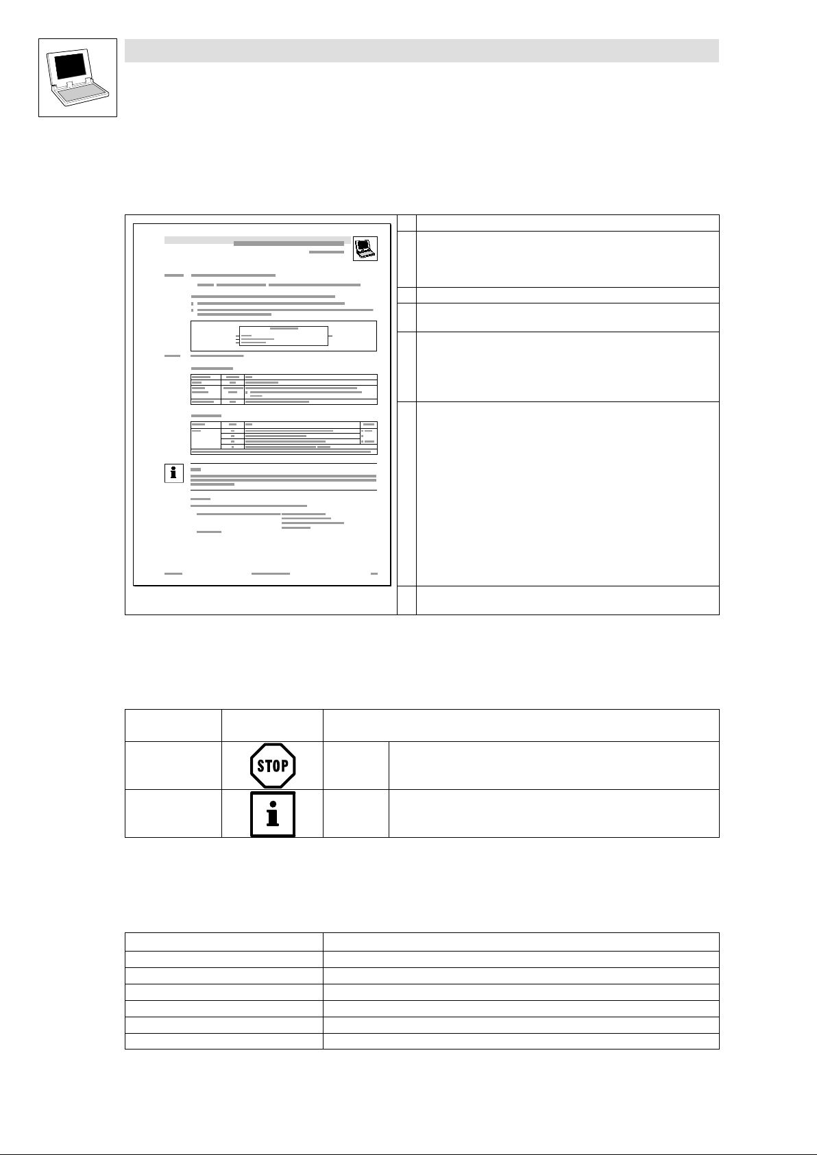
1.1.2 Structure of function descriptions
All function descriptions given in this Manual have the same structure:
Headline stating the function and the function identifier
Declaration of the function:
· Data type of the feedback value
· Function identifier
· List of transfer parameters
Short description of the function and its most important features
Function chart including all corresponding variables (transfer parameters
and feedback value)
Table giving information about the transfer parameters:
· Identifier
· Data type
· Possible settings
· Info
Table giving information about the feedback value:
· Data type of the feedback value
· Possible feedback values and their meaning:
Note
If a function cannot be executed properly, a negative feedback value
which is an error number, will be sent.
· Every error number stands for an error reason which is shown under
Meaning".
· If different error numbers (−1, −2, ...) are possible, every error
number is assigned to a certain priority (1, 2, ...) Functions
– The lower the number, the higher the priority,
i. e. 1" stands for highest priority.
– If several error reasons occur at the same time, the error number
with the highest priority will be sent first.
More information about the function
(Notes, tips, application examples, etc.)
1.1.3 Pictograms used in this Manual
Use of
pictograms
Warning of
material damage
Other notes Tip!
Signal words
Stop! Warns of potential damage to material .
Note!
1.1.4 Terminology used
Term In the following text used for
DDS Drive PLC Developer Studio
FB Function block
FP interface Lenze 2103 FP interface communication module
GDC Global Drive Control (parameter setting program from Lenze)
Parameter codes Codes for setting the functionality of a function block
SB System block
Consequences if disregarded:
Damage of the controller/drive system or its environment
Indicates a tip or note.
.
1−2
LenzeFpiDrv.lib EN 1.1
l
Page 6
LenzeFpiDrv.lib function library
Preface and general information
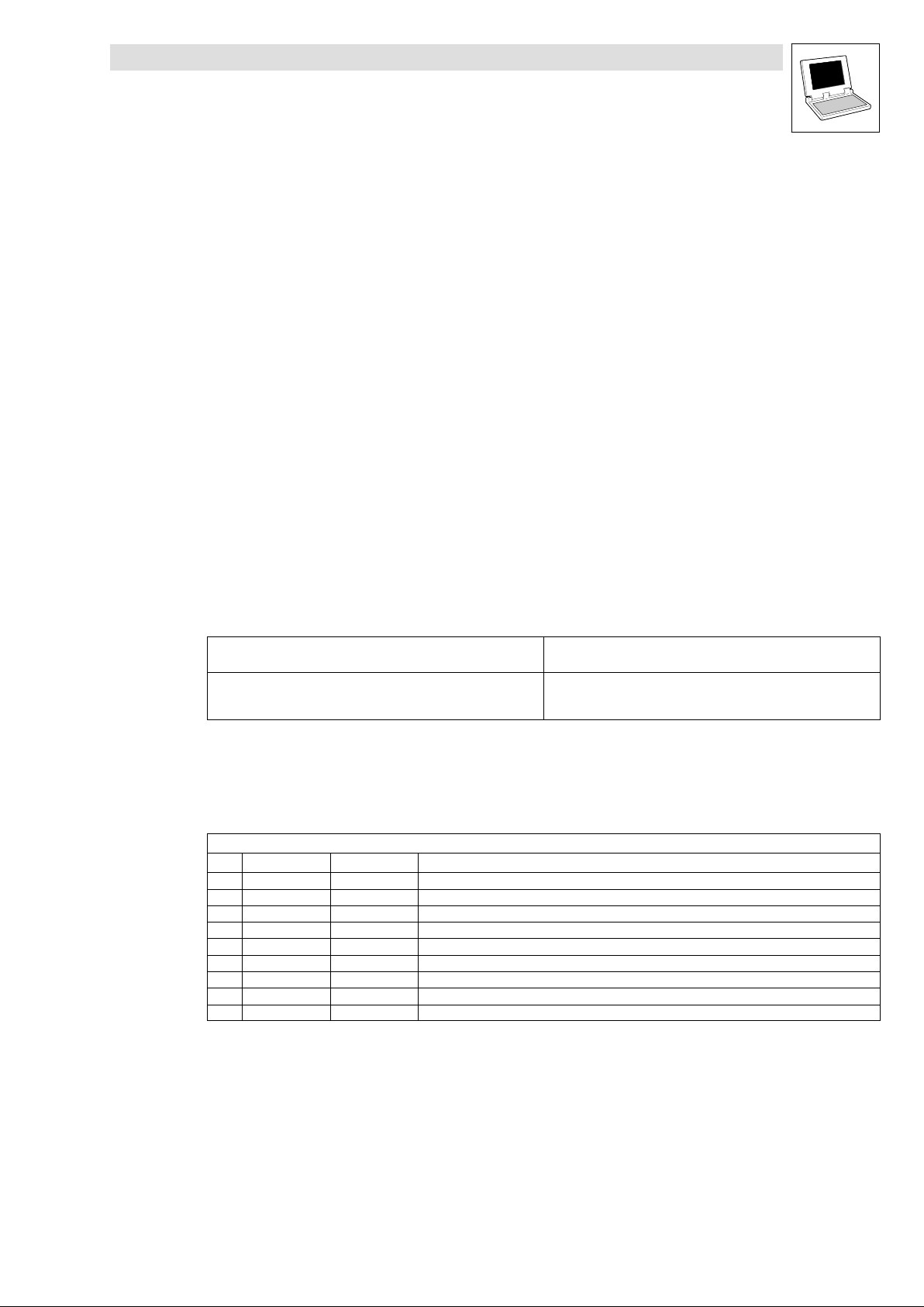
1.2 Version identifiers of the function library
The version of the function library can be found under the global constant
C_w[Function library name]Version .
Version identifiers as of PLC software version 7.x:
Constant Meaning
C_w[FunctionLibraryName]VersionER External Release 01
C_w[FunctionLibraryName]VersionEL External Level 05
C_w[FunctionLibraryName]VersionIR Internal Release 00
C_w[FunctionLibraryName]VersionBN Build No. 00
The value of this constant is a hexadecimal code.
· In the example, "01050000" stands for version "1.05".
Example
value
Version: 01 05 00 00
l
LenzeFpiDrv.lib EN 1.1
1−3
Page 7

LenzeFpiDrv.lib function library
Preface and general information
1−4
LenzeFpiDrv.lib EN 1.1
l
Page 8
LenzeFpiDrv.lib function library
General information about the RS−232C interface
2 General information about the RS−232C interface
RS−232C stands for Recommended Standard−232C, which is an American Standard of the EIA
(Electronic Industries Association). It describes the serial connection between a DTE (Data Terminal
Equipment) and a DCE (Data Communications Equipment) and all the electrical and mechanical
features.
· The RS−232C is often also described by the V.24/V.28, which is the international
recommendation of the CCITT (today knows as ITU − International Telecommunication Union).
The V.24 specifies the mechanical features and the V.28 the electrical features.
Although the standard RS−232C only describes the connection between a DTE and a DCE, the
RS−232C interface has been established as standard for serial data transmission over short
distances.
The following chapters inform about the mechanical and electrical features of the RS−232C interface
and the serial data transmission.
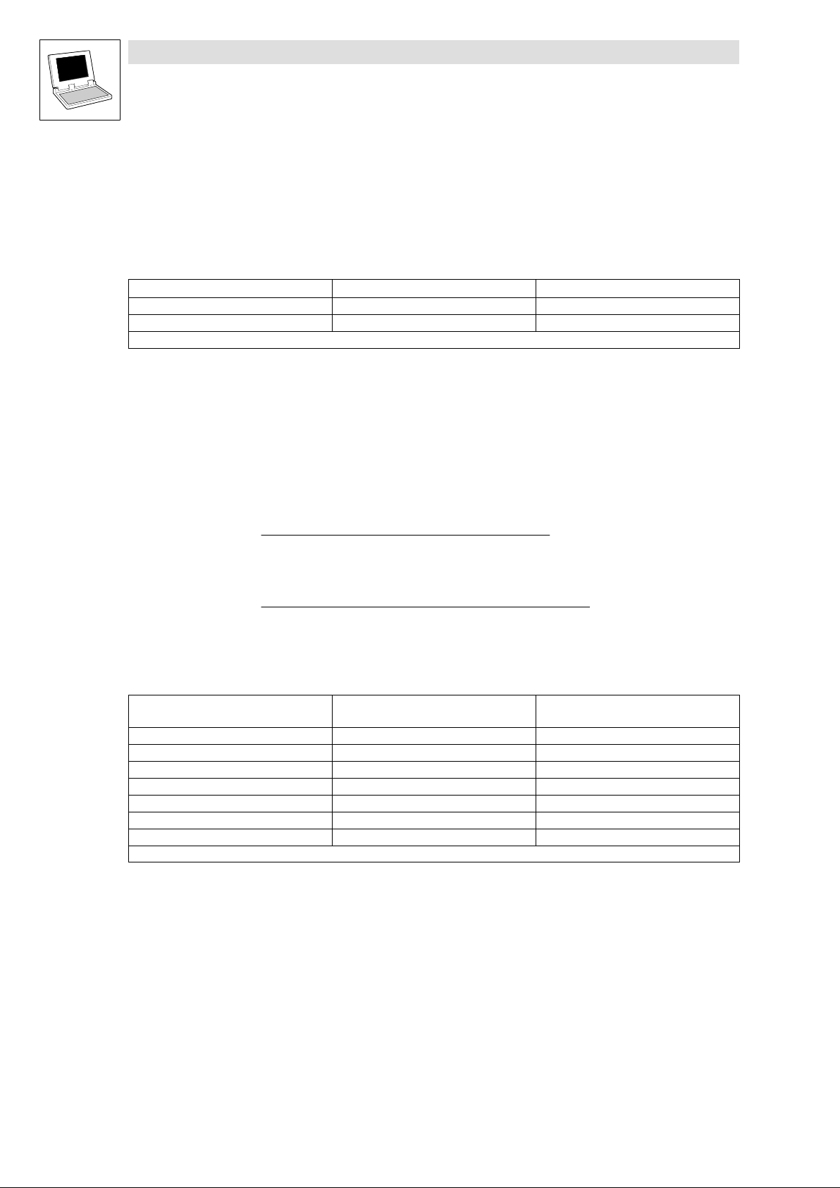
2.1 Mechanical features
2.1.1 Types of plug−in connectors
In general subminiature−D−plug−in connectors in 9 or 25−pole design are used as interface
connectors. They are distinguished as follows:
Master
(e. g. Lenze PLC with FP interface)
9−pole SubD connector (male)
or
25−pole SubD socket (female)
The FP interface requires a connection cable with a 9−pole SubD connector (male).
2.1.2 Terminal assignment with a FP interface
9−pole SubD socket for RS−232C interface
Pin Designation Input/output Explanation
1 − − not used
2 RxD Input Receive data
3 TxD Output Send data
4 DTR Output no function (logic 0")
5 GND − Reference potential
6 DSR Input no function
7 − − not used
8 − − not used
9 + 5V − max. output current 50 mA
Slave
9−pole SubD socket (female)
l
LenzeFpiDrv.lib EN 1.1
2−1
Page 9
LenzeFpiDrv.lib function library
General information about the RS−232C interface
2.2 Electrical features
2.2.1 Voltage level
The logical states of the individual bits are sent as voltage states via send or receive cables:
Logical state Voltage level Min. voltage level − sender*
1 −3 ... −15 V −5 V
0 +3 ... +15 V +5 V
The achievable distance between two RS−232C devices depends on the cable and baud rate used.
We recommend not to exceed a distance of 15 to 30 meters at a baud rate of 9600 baud.
2.2.2 Baud rate/data transmission rate
The baud rate indicates how many bits are transferred per second. This figure together with the other
transmission parameters (number of stop bits/data bits and parity bit) result in the data transmission
rate which is usually indicated in characters per second.
Transmissionrate +
Total number of bits transmitted per character
Baud rate
* at permissible ohmic load > 3 kW
Example
Transmissionrate +
1 (start bit) + 8 (data bits) + 1 (parity bit) + 1 (stop bit)
9600
+ 872 characters/s
The following table indicates the data transmission rates possible when using a FP interface for a
transmission with 8 data bits, 1 stop bit and even parity.
Baud rate*
(Bit/s)
600 18.33 54
1200 9.17 109
2400 4.58 218
4800 2.29 436
9600 1.15 872
19200 0.573 1745
38400 0.286 3490
* With the FP interface every 250 ms a character can be sent, therefore a baud rate higher than 38400 baud cannot be recommended.
Transmission time per character
(ms)
Data transmission rate
(characters/s)
2−2
LenzeFpiDrv.lib EN 1.1
l
Page 10

LenzeFpiDrv.lib function library
General information about the RS−232C interface
2.3 Synchronous/asynchronous transmission mode
Serial data transmission distinguishes between synchronous and asynchronous transmission.
· Synchronous transmission mode:
The data transmission between sender and receiver is synchronised by means of a clock
pulse. Thus the data cannot be send quicker than received and processed by the receiver.
· Asynchronous transmission mode:
The data transmission is not synchronised by means of a clock pulse. The so−called
hand−shake method avoids data loss during the transmission.
The FP interface supports the asynchronous transmission mode only!
2.4 Data flow check (handshake)
With asynchronous data transmission the receiver must be able to inform the sender that it is not
ready for processing new or more data. The data flow check is called handshake. There are two
different handshake methods:
· Hardware handshake:
The receiver controls the inputs CTS and/or DSR of the sender with its output DTR and/or RTS
via hardware cables.
– Advantage: transparent data transmission
– Disadvantage: additional cables required for the transmission of the handshake signals.
· Software handshake:
The recipient sends special characters to the sender to control the data flow, e. g. XON/XOFF.
(^ 2−5, ASCII character set)
– Advantage: Only data cables required for data transfer
– Disadvantage: The characters used for controlling the data flow must not be part of the user
data.
The FP interface supports the software handshake only!
2.5 Transmission parameters
With a serial, asynchronous data transmission the character to be transmitted is transmitted via the
data cable as bit sequence:
· A bit sequence for a character is always started by a start bit which is send as logic "0".
· The character is then transmitted as sequence of 7 or 8 bits starting with the least significant
bit (LSB).
· The bit sequence for the character can be followed by a parity bit which can be used for
detecting transmission errors.
· The bit sequence is ended by one or 2 stop bits, which are always send as logic "1".
l
LenzeFpiDrv.lib EN 1.1
2−3
Page 11

LenzeFpiDrv.lib function library
General information about the RS−232C interface
Example: Bit sequence/voltage level for a character to be transmitted
Character: A" (ASCII)
01000001 (bin)
65 (dez)
41 (hex)
Parity*: Even
Stop bits: 2
Data bits: 7
When using 7 data bits, a parity bit will always be created so that the setting No parity" (byParity = 0) is not admissible!
Character: A" (ASCII)
01000001 (bin)
65 (dez)
41 (hex)
Parity: Even
Stop bits: 2
Data bits: 8
+3...+15V
Start
−3...−15V
(Neutral level)
+3...+15V
Start
−3...−15V
(Neutral level)
LSB
Bit10Bit20Bit30Bit4
1
0
LSB
Bit10Bit20Bit30Bit4
1
0
0
0
Bit5
MSB1Parity0Stop1Stop
0
Bit50Bit6
MSB0Parity0Stop1Stop
1
2
2
For a successful communication between sender and receiver, the transmission parameters (baud
rate, data bits, parity bit, stop bits) must be set identically for both.
· The transmission parameters of the FP interface are configured using the function
L_Rs232Open.
Parity bit
(^ 3−1)
The parity bit serves as control bit for data transmission, similar to a check sum. We distinguish
between even and odd parities, a parity bit can be deactivated (parity None"):
· Even parity:
The sender transfers 0" as parity bit, if an even number of data bits with valency 1" has been
transferred.
· Odd parity:
The sender transfers 0" as parity bit, if an uneven number of data bits with valency 1" has
been transferred.
· None
No transfer of parity bits.
The parity bit can be used for a "Parity check":
During data transfer the sender determines the parity of the data bits. The parity bit "informs" the
receiver. The receiver calculates the parity of the data bits received and compares the parity with the
parity bit received. It is thus possible to detect transmission error in a bit (1−bit error). It is however
not possible to detect 2−bit errors (two wrong data bits have been transferred), since the parity does
not change.
2−4
LenzeFpiDrv.lib EN 1.1
l
Page 12

General information about the RS−232C interface
2.6 ASCII character set
2.6.1 Standard
The following table shows the assignment of the standard ASCII character set (characters 0 − 127):
HEX DEC CHAR CTRL HEX DEC CHAR HEX DEC CHAR HEX DEC CHAR
00 0 NUL ^@
01 1 SOH ^A 21 33 ! 41 65 A 61 97 a
02 2 STX ^B 22 34 " 42 66 B 62 98 b
03 3 ETX ^C 23 35 # 43 67 C 63 99 c
04 4 EOT ^D 24 36 $ 44 68 D 64 100 d
05 5 ENQ ^E 25 37 % 45 69 U 65 101 e
06 6 ACK ^F 26 38 & 46 70 F 66 102 f
07 7 BEL ^G 27 39 ’ 47 71 G 67 103 g
08 8 BS ^H 28 40 ( 48 72 H 68 104 h
09 9 HT ^I 29 41 ) 49 73 I 69 105 i
0A 10 LF ^J 2A 42 * 4A 74 J 6A 106 j
0B 11 VT ^K 2B 43 + 4B 75 K 6B 107 k
0C 12 FF ^L 2C 44 , 4C 76 L 6C 108 l
0D 1313 CR ^M 2D 45 − 4D 77 M 6D 109 m
0E 14 SO ^N 2E 46 . 4E 78 N 6E 100 n
0F 15 SI ^O 2F 47 / 4F 79 O 6F 111 o
10 16 DLE ^P 30 48 0 50 80 P 70 112 p
11 17 DC1 ^Q 31 49 1 51 81 Q 71 113 q
12 18 DC2 ^R 32 50 2 52 82 R 72 114
1313 19 DC3 ^S 33 51 3 53 83 S 73 115 s
14 20 DC4 ^T 34 52 4 54 84 T 74 116 t
15 21 NAK ^U 35 53 5 55 85 a 75 117 amb
16 22 SYN ^V 36 54 6 56 86 V 76 118 v
17 23 ETB ^W 37 55 7 57 87 W 77 119 w
18 24 CAN ^X 38 56 8 58 88 X 78 120 x
19 25 EM ^Y 39 57 9 59 89 Y 79 121 y
1A 26 SUB ^Z 3A 58 : 5A 90 Z 7A 122 z
1B 27 ESC ^[ 3B 59 ; 5B 91 [ 7B 123 {
1C 28 FS ^\ 3C 60 < 5C 92 \ 7C 124 |
1D 29 GS ^] 3D 61 = 5D 93 ] 7D 125 }
1E 30 RS ^^ 3E 62 > 5E 94 ^ 7E 126 ~
1F 31 US ^_ 3F 63 ? 5F 95 _ 7F 127 DEL
20 32 SP 40 64 @ 60 96
LenzeFpiDrv.lib function library
l
LenzeFpiDrv.lib EN 1.1
2−5
Page 13

LenzeFpiDrv.lib function library
General information about the RS−232C interface
2.6.2 Extended, Latin−1
The following table describes the assignment of the extended ASCII character set
(Latin−1, characters 128 − 255):
HEX DEC CHAR HEX DEC CHAR HEX DEC CHAR HEX DEC CHAR
80 128 PAD
81 129 HOP A1 161 ¡ C1 193 Á E1 225 á
82 130 BPH A2 162 BY C2 194 Â E2 226 â
83 131 NBH A3 163 £ C3 195 Ã E3 227 ã
84 132 IND A4 164 ¤ C4 196 Ä E4 228 ä
85 133 NEL A5 165 ¥ C5 197 Å E5 229 å
86 134 SSA A6 166 | C6 198 Æ E6 230 æ
87 135 ESA A7 167 õ C7 199 Ç E7 231 ç
88 136 HTS A8 168 C8 200 È E8 232 è
89 137 HTJ A9 169 © C9 201 É E9 233 é
8A 138 VTS AA 170 ª CA 202 Ê EA 234 ê
8B 139 PLD AB 171 « CB 203 Ë EB 235 ë
8C 140 PLU AC 172 ¬ CC 204 Ì EC 236 ì
8D 141 RI AD 173 − CD 205 Í ED 237 í
8E 142 SS2 AE 174 ® CE 206 Î EE 238 î
8F 143 SS3 AF 175 CF 207 Ï EF 239 ï
90 144 DCS B0 176 ° D0 208 Ð F0 240 ð
91 145 PU1 B1 177 ± D1 209 Ñ F1 241 ñ
92 146 PU2 B2 178 D2 210 Ò F2 242 ò
93 147 STS B3 179 D3 211 Ó F3 243 ó
94 148 CCH B4 180 ’ D4 212 Ô F4 244 ô
95 149 MW B5 181 μ D5 213 { F5 245 õ
96 150 SPA B6 182 ô D6 214 Ö F6 246 ö
97 151 EPA B7 183 ⋅ D7 215 × F7 247 ÷
98 152 SOS B8 184 D8 216 ∅ F8 248 ø
99 153 SGCI B9 185 D9 217 Ù F9 249 ù
9A 154 SCI BA 186 º DA 218 Ú FA 250 ú
9B 155 CSI BB 187 » DB 219 Û FB 251 û
9C 156 ST BC 188 1/4 DC 220 Ü FC 252 ü
9D 157 OSC BD 189 1/2 DD 221 Ý FD 253 ý
9E 158 PM BE 190 ¾ DE 222 Þ FE 254 þ
9F 159 APC BF 191 ¿ DF 223 ß FF 255 ÿ
A0 160 NBS C0 192 À E0 224 à
2−6
LenzeFpiDrv.lib EN 1.1
l
Page 14

LenzeFpiDrv.lib function library
General information about the RS−232C interface
2.6.3 Meaning of control characters
HEX Name Meaning HEX Name Meaning
00 <nul> zero 11 <dc1> Device control 1 / XON
01 <soh> Start of header 12 <dc2> Device control 2
02 <stx> Start of text 1313 <dc3> Device control 3 / XOFF
03 <etx> End of text 14 <dc4> Device control 4
04 <eot> End of transmission 15 <nak> Negative acknowledgment
05 <enq> Enquiry 16 <syn> Synchronous idle
06 <ack> Acknowledgment 17 <etb> End of transmission block
07 <bel> Bell 18 <can> Cancel
08 <bs> Backspace 19 <em> End of medium
09 <ht> Horizontal tab 1A <sub> Substitute character
0A <lf> Line feed 1B <esc> Escape
0B <vt> Vertical tab 1C <fs> File separator
0C <ff> Form feed 1D <gs> Group separator
0D <cr> Carriage return 1E <rs> Record separator
0E <so> Shift out 1F <us> Unit separator
0F <si> Shift in
10 <dle> Data link escape 7F <del> Delete
l
LenzeFpiDrv.lib EN 1.1
2−7
Page 15

LenzeFpiDrv.lib function library
General information about the RS−232C interface
2−8
LenzeFpiDrv.lib EN 1.1
l
Page 16

LenzeFpiDrv.lib function library
Functions
3.1 Initialisation (L_Rs232Open)
3 Functions
3.1 Initialisation (L_Rs232Open)
DWORD L_Rs232Open (wDrvNr, dwBaudrate, byNumberOfDataBits,
byNumberOfStopBits, byParity)
The interface must be initialised with the required transfer parameters using this function before it is
possible to work with the FP interface.
Note!
· After the initialisation has been completed successfully, the automation interface (AIF) only
works with the FP interface.
· Other AIF modules (keypad, INTERBUS−S, PROFIBUS−DP, etc.) will only be accepted after
execution of the function L_Rs232Close.
· If this function is called up again, the interface can be changed over to other transfer
parameters. This however results in a cancellation of all existing send and receipt orders!
Fig. 3−1 Initialisation (L_Rs232Open)
Transfer parameter
Identifier Data type Possible settings Info
wDrvNr Word 30 AIF interface
dwBaudrate Double Word 600, 1200, 2400, 4800
byNumberOfDataBits Byte 7 or 8 Number of data bits*
byNumberOfStopBits Byte 1 or 2 Number of stop bits
byParity Byte 0: None
L_Rs232Open
wDrvNr
dwBaudrate
byNumberOfDataBits
byNumberOfStopBits
byParity
Baud rate
9600, 19200, 38400
Parity*
1: Even
2: Odd
* When using 7 data bits, a parity bit will always be created so that the setting No parity"
(byParity = 0) is not admissible!
L
LenzeFpiDrv.lib EN 1.1
3−1
Page 17

LenzeFpiDrv.lib function library
Functions
3.1 Initialisation (L_Rs232Open)
Feedback value
Data type Bit Value Meaning Priority
Double Word 0
6−15 Reserved for future extensions (bits set to 0).
16−31 Version of the FPI driver
0 Driver is initialised. −
1 Error during initialisation.
1
0 Driver setting Ok.
1 Selected driver ( wDrvNr ) is not available on target system.
2
0 Baud rate setting Ok.
1 Selected baud rate ( dwBaudrate ) is not available.
3
0 Data bits setting Ok.
1 Wrong number of data bits ( byNumberOfDataBits ).
4
0 Stop bits setting Ok.
1 Wrong number of stop bits ( byNumberOfStopBits ).
5
0 Parity setting Ok.
1 Wrong parity setting ( byParity ).
Format: main version/subversion (e. g. 0103hex = version 1.03)
Example
Calling up the function in ST with decading of the feedback value:
(* open FPI − returns g_dwOpenStatus *)
g_dwOpenStatus := L_Rs232Open (30, 4800, 8, 1, 1);
g_bInitOK := NOT DWORD_TO_BOOL (g_dwOpenStatus AND 16#0000_00001);
g_bDriverFail := DWORD_TO_BOOL ( SHR (g_dwOpenStatus,1) AND 16#0000_0001);
g_bBaudrateFail:= DWORD_TO_BOOL ( SHR (g_dwOpenStatus,2) AND 16#0000_0001);
g_bDatabitsFail:= DWORD_TO_BOOL ( SHR (g_dwOpenStatus,3) AND 16#0000_0001);
g_bStopbitsFail:= DWORD_TO_BOOL ( SHR (g_dwOpenStatus,4) AND 16#0000_0001);
g_bParityFail := DWORD_TO_BOOL ( SHR (g_dwOpenStatus,5) AND 16#0000_0001);
g_wVersion := DWORD_TO_WORD ( SHR (g_dwOpenStatus,16) AND 16#FFFF);
3−2
LenzeFpiDrv.lib EN 1.1
L
Page 18

LenzeFpiDrv.lib function library
Functions
3.2 Deactivation (L_Rs232Close)
3.2 Deactivation (L_Rs232Close)
BOOL L_Rs232Close (wDrvNr)
This function deactivates the FP interface so that the AIF interface can be used for other AIF modules
(keypad, INTERBUS−S, PROFIBUS−DP, etc.) again.
· All send and receipt orders not carried out yet are cancelled when this function is activated.
L_Rs232Close
wDrvNr
Fig. 3−2 Deactivation (L_Rs232Close)
Transmission parameters
Identifier Data type Possible settings Info
wDrvNr Word 30 AIF interface
Feedback value
Data type Value Meaning Priority
bool (boolean)
sends FALSE Error during deactivation of the driver
Wrong driver number ( wDrvNr ) or driver not initialised.
TRUE Driver has been deactivated.
Example
Calling up the function in ST:
(* close FPI − returns g_bFPICloseState *)
g_bFPICloseState := L_Rs232Close (30)
−
L
LenzeFpiDrv.lib EN 1.1
3−3
Page 19

LenzeFpiDrv.lib function library
Functions
3.3 Send data (L_Rs232SendData)
3.3 Send data (L_Rs232SendData)
INT. L_Rs232SendData (wDrvNr, pabySendDataMemory, wNumberOfBytes)
With this function data can be send via the FP interface.
· The operating system of the controller sends data and executes the PLC program at the same
time, i.e. a byte can be sent every max. 250 ms.
· A max. of 32767 characters can be send per function call.
· A new call is only possible after the previous call has been processed, i.e. after all data has
been send.
· An active sending process can be cancelled by repeating the function L_Rs232Open. It is
then possible to receive data which have been changed.
L_Rs232SendData
wDrvNr
pabySendDataMemory
wNumberOfBytes
Fig. 3−3 Send data (L_Rs232SendData)
Transfer parameter
Identifier Data type Possible settings Info
wDrvNr Word 30 AIF interface
pabySend
DataMemory
wNumberOfBytes Word 1 ... 32767 Number of data bytes to be sent
Pointer to Array
of Byte
Feedback value
Data type Value Meaning Priority
Integer
−4 Pointer of send memory does not point to PLC−RAM. 4
−3 Number of bytes to be sent exceeding its limits (1 ... 32767). 3
−2 Send order not passed on to the operating system since the previous send order is not
−1 Wrong driver number (wDrvNr) or driver not initialised. 1
0 Send order successfully transferred to operating system.
Pointer set onto the address in
the memory where the data
bytes to be sent are stored.
completed yet.
Note: If errors are caused by several problems, the error cause with the highest priority sends back the
corresponding feedback value.
The address of a variable (e. g. data array) can be detected using
the address function ADR.
2
3−4
Tip!
Sending is executed at the same time as the PLC program.
Please ensure that all send orders are completed before calling up this function, otherwise an error
will occur (feedback value = −2).
LenzeFpiDrv.lib EN 1.1
L
Page 20

LenzeFpiDrv.lib function library
Functions
3.3 Send data (L_Rs232SendData)
Example 1
Calling up the function in ST for a single send order:
g_nSendStatus: = L_Rs232SendData(30,
ADR(g_abySendData),
g_wNumberOfBytesToSend);
Example 2
Calling up the function in ST with monitoring of the last send order:
(* read state of sendprocess and send new data *)
(* if last sendprocess is finished *)
IF L_Rs232GetSendState (30) = 0 THEN
g_nSendStatus: = L_Rs232SendData(30,
ADR(g_abySendData),
g_wLength);
END_IF
Note!
Addresses within the memory range of the operating system are not permitted with the functions
L_Rs232SendData and L_Rs232ReceiveData !
Problem:
Also the system variable addresses (inputs/outputs) are in the memory
range of the operating system, in the following figure it is the system
variable AIN1_nIn_a:
L_Rs232SendData
wDrvNr
30
AIN1_nIn_a
ADR
pabySendDataMemory
wNumberOfBytes
2
Remedy:
Instead of using a system variable address, use an intermediate
variable address to copy the corresponding system variable value to.
AIN1_nIn_a
nAnalogInput
nAnalogInput
ADR
L_Rs232SendData
wDrvNr
30
pabySendDataMemory
wNumberOfBytes
2
L
LenzeFpiDrv.lib EN 1.1
3−5
Page 21

LenzeFpiDrv.lib function library
Functions
3.4 Send status (L_Rs232GetSendState)
3.4 Send status (L_Rs232GetSendState)
INT L_Rs232GetSendState (wDrvNr)
Use this function to find out about the current status of a send order.
L_Rs232GetSendState
wDrvNr
Fig. 3−4 Send status (L_Rs232GetSendState)
Transmission parameters
Identifier Data type Possible settings Info
wDrvNr Word 30 AIF interface
Feedback value
Data type Value Meaning Priority
Integer
−1 Wrong driver number ( wDrvNr ) or driver not initialised. −
0 All data bytes have been sent, the memory is ready for further orders.
1 ... 32767 Number of data bytes to be sent when a send order is active.
Example
Calling up the function in ST:
g_dnStatusOfSend := L_Rs232GetSendState(30);
3−6
LenzeFpiDrv.lib EN 1.1
L
Page 22

LenzeFpiDrv.lib function library
Functions
3.5 Receive data (L_Rs232ReceiveData)
3.5 Receive data (L_Rs232ReceiveData)
INT. L_Rs232ReceiveData (wDrvNr, pabyReceiveDataMemory, wBuffersize,
wTimeOut ,wNumberOfBytes,
byEndChar1, byEndChar2, wControl)
With this function data can be received via the FP interface.
· The operating system of the controller receives data and executes the PLC program at the
same time.
· A max. of 32767 characters can be received per function call.
· A new call is only possible after the previous call has been processed, i.e. after all data has
been received or the end of reception has been detected.
· An active receiving process can be cancelled by repeating the function L_Rs232Open . It is
then possible to receive data which has been changed, if necessary.
L_Rs232ReceiveData
wDrvNr
pabyReceiveDataMemory
wNumberOfReceiveBytes
wBufferSize
wTimeOut
byEndChar1
byEndChar2
wControl
Fig. 3−5 Receive data (L_Rs232ReceiveData)
Transfer parameters
Identifier Data type Possible settings Info
wDrvNr Word 30 AIF interface
pabyReceive
DataMemory
wBuffersize Word 2 ... 32767 Size of the receive memory in bytes
wNumberOf
ReceiveBytes
wTimeOut Word 2 ... 60000 Time out time (in ms) for receiving data
byEndChar1 Byte 0 ... 255 Character which defines the end of the data byte to be received.
byEndChar2 Byte 0 ... 255 Character which defines the end of the data byte to be received.
Pointer to Array
of Byte
Word 1 ... 32767 Number of data bytes to be received
Pointer set onto the address in
the memory where the storage
of the received data bytes is to
start.
The address of a variable (e. g. data array) can be detected using
the address function ADR .
· The memory has a minimum size of two bytes.
· This parameter can be used for checking the end of data
reception (see wControl).
· This parameter can be used for checking the end of data
reception (see wControl).
· This parameter can be used for checking the end of data
reception (see wControl).
· This parameter can be used for checking the end of data
reception (see wControl).
L
LenzeFpiDrv.lib EN 1.1
3−7
Page 23

LenzeFpiDrv.lib function library
Functions
3.5 Receive data (L_Rs232ReceiveData)
Identifier InfoPossible settingsData type
wControl Word End of receiving data after: Checking the end of data reception
Bit 0: wTimeOut
Bit 1: wNumberOfBytes
Bit 2: byEndChar1
Bit 3: byEndChar2
Return value
Data type Value Meaning Priority
Integer
−6 wControl is invalid since reserved bits have been overwritten. 6
−5 Time out time exceeds its limits (2 ... 60000 ms). 5
−4 Number of bytes to be received > receive memory (1 ... 32767) or
Number of bytes to be received = 0.
−3 Receive memory size exceeds its limits (2 ... 32767). 3
−2 Pointer of receive memory does not point to PLC−RAM. 2
−1 Wrong driver number (wDrvNr) or driver not initialised. 1
Note: If errors are caused by several problems, the error cause with the highest priority sends back the
corresponding feedback value.
0 Receive order successfully transferred to operating system.
0: not active
1: active
0: not active
1: active
0: not active
1: active
0: not active
1: active
Bits 4−15 are reserved for future extensions
4
Receive/send check
The way of how to detect the end of receiving data and whether the unit is read for receiving data can
be configured with beendet wird, kann mit Hilfe von wControl :
Data reception is stopped when wControl Priority
the memory is full. (This check test is always active.) 1
a certain waiting time is over wTimeOut no bytes have been received 0000 0000 0000 0001 2
the number of wNumberOfReceiveBytes bytes have been received 0000 0000 0000 001x 3
the character byEndChar1 has been received 0000 0000 0000 010x 4
the character byEndChar2 has been received 0000 0000 0000 100x 5
the character byEndChar1 and byEndChar2 have been received subsequently 0000 0000 0000 110x 6
(x: any status)
Example:
wControl = 0x0009
= 0000 0000 0000 100 1
hex
bin
End of receiving data wTimeOut is active
End of receiving data byEndChar2 is active
Caution!
Please ensure that the size of the created memory (e. g. an array) does not fall below value indicated
in wBuffersize since otherwise the check test of the memory limits will not work.
This can result in an impermissible overwriting of the memory and result in errors!
3−8
Receive memory is full
If the receive memory is full and data is sent to be received, the receiving process will be stopped
immediately. By this it is avoided that the memory is overwritten with received data.
LenzeFpiDrv.lib EN 1.1
L
Page 24

LenzeFpiDrv.lib function library
Functions
3.5 Receive data (L_Rs232ReceiveData)
TimeOut
The activation of this function starts a time out timer. The timer will be reset with every byte received.
If the time wTimeOut has expired without receiving data, a TimeOut error will be set and the unit is
no longer ready for receiving data.
NumberOfReceiveBytes
If wNumberOfReceiveBytes bytes have been received, the receiving process will be stopped.
Ending character (byEndChar1/byEndChar2)
With asynchronous data transmission, the data flow is checked by defining a start and an end
character between the sender and receiver. The end character indicates the end of a data package
sent and must be recognised accordingly by the receiver. Sometimes the end character consists of
a character pair.
Use byEndChar1 and byEndChar2 to define these end characters. The receiving process is over
when the defined end character is recognised by the receiver. The end characters are stored in the
receive memory.
Example
Calling the function in ST:
g_nReceiveStatus:= L_Rs232ReceiveData(30,
ADR(g_abyReceiveData),
g_wLength,
g_wReceiveBufferSize,
g_wTimeOut,
g_byEndChar1,
g_byEndChar2,
g_wControl);
Note!
Addresses within the memory range of the operating system are not permitted with the functions
L_Rs232SendData and L_Rs232ReceiveData !
· See also the note for L_Rs232SendData. (^ 3−4)
L
LenzeFpiDrv.lib EN 1.1
3−9
Page 25

LenzeFpiDrv.lib function library
Functions
3.6 Receive status (L_Rs232GetReceiveState)
3.6 Receive status (L_Rs232GetReceiveState)
INT L_Rs232GetReceiveState (wDrvNr, bStateControl)
Use this function to find out about the current status of a receive order and to output the information
according to bStateControl :
If bStateControl is
· FALSE an error code will be sent at reception if an error has occurred. Other the number of
bytes received will be sent.
· TRUE the number of bytes already received will be sent, independently of the number of error
that have occurred.
L_Rs232GetReceiveState
wDrvNr
bStateControl
Fig. 3−6 Receive status (L_Rs232GetReceiveState)
Transfer parameter
Identifier Data type Possible settings Info
wDrvNr Word 30 AIF interface
bStateControl bool (boolean) FALSE Feedback value is receive status
TRUE Feedback value is number of bytes received
Feedback value
bStateControl = FALSE
Data type Value Meaning Priority
Integer
−7 Frame error of the serial interface (incorrect setting of number of stop bits). 2
−6 Overrun error of the serial interface (incorrect setting of baud rate). 3
−5 Parity error of the serial interface (wrong parity setting). 4
−4 Reception aborted since memory is full. 5
−3 TimeOut time has been exceeded or
no reception during the time−out time.
−2 Last reception order not completed yet. 7
−1 Wrong driver number (wDrvNr) or driver not initialised. 1
Note: If errors are caused by several problems, the error cause with the highest priority sends back the
corresponding feedback value. The data already received will also be stored in the receive memory if
the feedback value is negative.
0 ... 32767 Number of data bytes received after end has been recognised.
6
3−10
bStateControl = TRUE
Data type Value Meaning Priority
Double−integer
−1 Wrong driver number (wDrvNr) or driver not initialised. −
0 ... 32767 Number of data bytes received (independent of end or errors).
LenzeFpiDrv.lib EN 1.1
L
Page 26

LenzeFpiDrv.lib function library
Functions
3.6 Receive status (L_Rs232GetReceiveState)
Example
Calling up the function in ST:
(* read receive state *)
ReturnValue := L_Rs232GetReceiveState (30, FALSE);
(* Receive Error? *)
IF (ReturnValue < 0) THEN
(* Receive Error *)
(* get error code and number *)
(* of received bytes in case of error *)
g_nReceiveErrorCode := ReturnValue;
g_wNumberOfReceivedBytes_Error := L_Rs232GetReceiveState (30, TRUE);
ELSE
(* No Receive Error *)
(* get number of received bytes *)
g_wNumberOfReceivedBytes_NoError := ReturnValue;
END_IF
L
LenzeFpiDrv.lib EN 1.1
3−11
Page 27

LenzeFpiDrv.lib function library
Functions
3.6 Receive status (L_Rs232GetReceiveState)
3−12
LenzeFpiDrv.lib EN 1.1
L
 Loading...