

BA 12.0032-EN
.&j#
Ä.&j#ä
Operating Instructions
G-motion
GKK
Bevel gearbox with clutch

Product key
Gearbox
type
GKK
Gearbox
size
Bevel gearbox
with clutch
Stage
number
Three-phase
motor
GKK mounting positions
A B
Input design
Solid shaft
M
Foot-mounting with
centring
Without foot mounting
with centering
Output design Drive size
V
A
C
without flange
R
with circularflange
l
(threaded holes)
with square flange
N
(through holes)
Example motor
071 C 32
bearing flange / free input shaft
Example
1C
C D
Additions / changes to the Operating Instructions
Material number Edition Important Contents
13017201 1.0 08/2004 TD09 1st edition First printing
13057302 2.0 06/2005 TD09 2nd edition
replaces 13017201
Revision of sections Mounting positions, Transport weights,
Breather position and Lubricant tables
2
BA 12.0032-EN 2.0
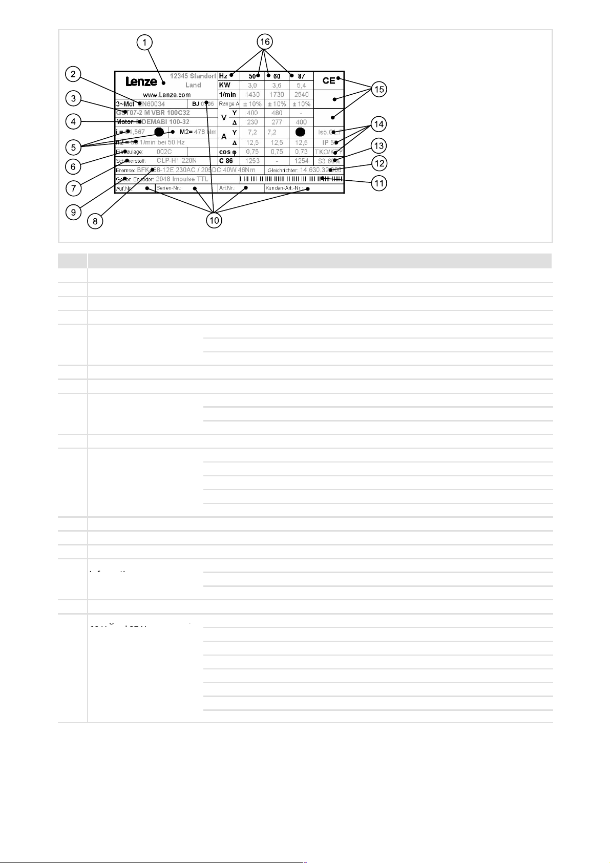
Pos. Contents
g
,
1 Production site
2 Motor identification
3 Gearbox type
4 Motor type
5 Technical data
6 Mounting position
7 Lubricant
8 Brake data
9 Encoder specifications if any
10 Production data
11 Bar code
12 Rectifier name
13 Informationontheoperatingmode
14 Additional motor
information
15 Valid conformities and approvals
16 Ratings for 50 Hz,
60 Hz and 87 Hz
Ratio
Rated torque
Ratedspeedandratedfrequency
Type
AC/DC and brake voltage
Brake torque
Order number
Serial number
Week of production / Year of production
Material number
Customer order number / Additional customer data
Temperature class
Enclosure
Motor protection
Hz = output frequency
kW = Motor power
1/min. = Motor speed
Range A = Voltage tolerances
V = Motor voltage
A = Motor current
cos ϕ = Motor power factor
C 86 = Code 0086, selection code for operation at servo inverter
GXX - 001. iso - TD
BA 12.0032-EN 2.0
3

© 2005 Lenze Drive Systems GmbH, Hans-Lenze-Straße 1, D-31855 Aerzen
No part of this documentation may be reproduced or made accessible to third parties without written consent by Lenze Drive
Systems GmbH.
All information given in this d ocumentation has been selected carefully and complies with the hardware and software described.
Nevertheless, deviations cannot be ruled out. We do not take any responsibility or liability for damages which might possibly occur.
Necessary corrections will be included in subsequent editions.
4
BA 12.0032-EN 2.0

Contents i
1 Preface and general information 7............................................
1.1 About these Operating Instructions 7.....................................
1.2 Terminology used 7....................................................
1.3 Scope of supply 7......................................................
1.4 Lenze drive systems 8...................................................
1.4.1 Labelling 8....................................................
1.4.2 Application as directed 8........................................
1.5 Legal regulations 8.....................................................
2 Safety instructions 9.........................................................
2.1 Personnel responsible for safety 9........................................
2.2 General safety information 9............................................
2.3 Definition of notes used 10...............................................
3 Technical data 11............................................................
3.1 Characteristics for light load application 11.................................
3.2 Characteristics for heavy load application 12................................
3.3 Product features 12.....................................................
3.4 Transport weights 13....................................................
3.5 General data/operating conditions 13......................................
3.5.1 Temperatures 13................................................
3.5.2 Ambient conditions 13...........................................
4 Mechanical installation 14.....................................................
4.1 Storage 14.............................................................
4.2 Mounting 14...........................................................
4.3 Preparation 14..........................................................
4.3.1 General information about the assembly of drive systems 15...........
4.3.2 Assembly of transmission elements on solid shafts 15................
4.3.3 Gearboxes with breathers 16.....................................
4.3.4 Breather position, oil filling screw and drain plug 16..................
5 Electrical installation 17.......................................................
5.1 Motor connection 17....................................................
5.2 Frequency inverter connection 17.........................................
6 Commissioning and operation 18...............................................
6.1 Before switching on 18..................................................
6.2 During operation 18.....................................................
6.3 Clutches at the GKK gearbox 18...........................................
BA 12.0032-EN 2.0
5

Contentsi
6.4 Operation of clutch at GKK gearbox 19.....................................
6.4.1 Switching via clutch lever 19......................................
6.4.2 Manual switching 19............................................
7 Maintenance 20.............................................................
7.1 Maintenance intervals 20................................................
7.2 Maintenance operations 21...............................................
7.2.1 Roller bearing grease 21..........................................
7.2.2 Table of lubricants 22............................................
7.2.3 Replacing the lubricant 24........................................
8 Troubleshooting and fault elimination 26.......................................
9Disposal 27..................................................................
10 Notes 28....................................................................
6
BA 12.0032-EN 2.0

Preface and general information
About these Operating Instructions
1 Preface and general information
1.1 About these Operating Instructions
ƒ
These Operating Instructions are intended for safety-relevant operations on and
with the gearboxes G. They contain safety instructions which must be observed.
ƒ
All personnel working on and with the gearboxes G must have the Operating
Instructions available and observe the information and notes relevant for them.
ƒ
The Operating Instructions must always be complete and perfectly readable.
1.2 Terminology used
Term In the following text used for
Gearboxes Gearbox of product family G
1
Drive system Drive system with gearboxes G and other Lenze drive components
1.3 Scope of supply
ƒ
The drive systems are combined individually according to a modular design. The
scope of supply can be obtained from the pertinent papers.
ƒ
After receipt of the supply, check immediately whether it corresponds with the
accompanying papers. Lenze does not grant any warranty for subsequent claims.
Claim for
– visible transport damages immediately to the forwarder.
– visible deficiencies / incompleteness immediately to the responsible Lenze
subsidiary / agency.
BA 12.0032-EN 2.0
7

1
Preface and general information
Lenze drive systems
Labelling
1.4 Lenze drive systems
1.4.1 Labelling
Lenze drive systems are uniquely designated by the content of their nameplates.
Manufacturer
Lenze Drive Systems GmbH
Hans-Lenze-Straße 1
D-31855 Aerzen
1.4.2 Application as directed
ƒ
Lenze drive systems
– are intended for use in machinery and plant,
– must only be used for the purposes ordered and confirmed,
– must only be operated under the ambient conditions prescribed in these
Operating Instructions,
– must not be operated beyond their corresponding power limits.
Any other use shall be deemed inappropriate!
1.5 Legal regulations
Liability
ƒ
The information, data, and notes in the Operating Instructions were state of the art
at the time of printing. Claims referring to drive systems which have already been
supplied cannot be derived from the information, illustrations, and descriptions.
ƒ
We do not accept any liability for damage and operating interference caused by:
– inappropriate use,
– unauthorised modifications to the drive system,
– improper working on and with the drive system,
– operating faults,
– disregarding the Operating Instructions.
Warranty
ƒ
Conditions of warranty: see terms of sale and delivery of Lenze Drive Systems
GmbH.
ƒ
Warranty claims must be made to Lenze immediately after detecting the deficiency
or fault.
ƒ
The warranty is void where liability claims cannot be made.
8
BA 12.0032-EN 2.0

2 Safety instructions
2.1 Personnel responsible for safety
Operator
ƒ
An operator is any natural or legal person who uses the drive system or on behalf of
whom the drive system is used.
ƒ
The operator or his safety officer must ensure
– that all relevant regulations, instructions and legislation are observed.
– that only qualified personnel work with and on the drive system.
– that the personnel have the Operating Instructions available for all corresponding
operations.
– that non-qualified personnel are prohibited from working with and on the drive
system.
Safety instructions
Personnel responsible for safety
2
Skilled personnel
Skilled personnel are persons who - because of their education, experience, instructions,
and knowledge about corresponding standards and regulations, rules for the prevention
of accidents, and operating conditions - are authorised by the person responsible for the
safety ofthe plantto perform there quired actions and whoare able to recognise potential
hazards.
(See IEC 364, definition of skilled personnel)
2.2 General safety information
ƒ
This safety information does not claimed to be complete. In case of questions and
problems, please contact your Lenze representative.
ƒ
At the time of delivery the drive system meets the state of the art and ensures safe
basic operation.
ƒ
The drive system is a source of danger for persons, for the drive system itself, and for
other material assets of the operator, if
– unqualified personnel works with and on the drive system,
– the drive system is used inappropriately.
ƒ
The drive systems must be designed such that they perform their functions after
proper installation and with application as directed in fault-free operation and that
they do not cause hazar ds for persons. This also applies for their interaction with the
complete plant.
BA 12.0032-EN 2.0
ƒ
Be sure to take appropriate measures in the case of drive system failure so that no
material damage occurs.
ƒ
Operate the drive system only when it is in a proper state.
ƒ
Retrofittings, modifications, or redesigns of the drive system are basically
prohibited. Lenze must be contacted in all cases.
9

2
2.3 Definition of notes used
Safety instructions
Definition of notes used
The following signal words and symbols are used in this documentation to indicate
dangers and important information:
Safety instructions
Structure of safety instructions:
Pictograph and signal word Meaning
Application notes
Pictograph and signal word Meaning
Danger!
(characterises the type and severity of danger)
Note
(describes the danger and gives information about how to prevent dangerous
situations)
Danger of personal injury through dangerous electrical
voltage.
Danger!
Danger!
Stop!
Note!
Reference to an imminent danger that may result in death or
serious personal injury if the corresponding measures are not
taken.
Danger of personal injury through a general source of danger.
Reference to an imminent danger that may result in death or
serious personal injury if the corresponding measures are not
taken.
Danger of property damage.
Reference to a possible danger that may result in property
damage if the corresponding measures are not taken.
Important note to ensure trouble-free operation
10
X
H
Tip!
Useful tip for simple handling
Reference to another documentation
BA 12.0032-EN 2.0
 Loading...