

Page 1
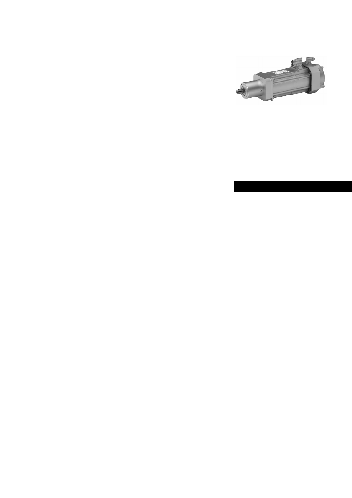
g700
g700−P20 ... g700−P800 | 5 Nm ...
800 Nm
Planetary gearboxes with servo
Mounting Instructions
EN
.O10
Ä.O10ä
Page 2

First read this documentation and the documentation of the motor before you start
working.
Observe the safety instructions contained therein.
0Abb. 0Tab. 0
Page 3
Contents i
1 About this documentation 4. . . . . . . . . . . . . . . . . . . . . . . . . . . . . . . . . . . . . . . . . . . . . . . . . . . . . .
1.1 Document history 4. . . . . . . . . . . . . . . . . . . . . . . . . . . . . . . . . . . . . . . . . . . . . . . . . . . . .
1.2 Conventions used 4. . . . . . . . . . . . . . . . . . . . . . . . . . . . . . . . . . . . . . . . . . . . . . . . . . . . . .
1.3 Terminology used 5. . . . . . . . . . . . . . . . . . . . . . . . . . . . . . . . . . . . . . . . . . . . . . . . . . . . .
1.4 Notes used 5. . . . . . . . . . . . . . . . . . . . . . . . . . . . . . . . . . . . . . . . . . . . . . . . . . . . . . . . . . .
2 Safety instructions 6. . . . . . . . . . . . . . . . . . . . . . . . . . . . . . . . . . . . . . . . . . . . . . . . . . . . . . . . . . . . .
2.1 General safety instructions for drive components 6. . . . . . . . . . . . . . . . . . . . . . . . . . .
3 Product description 7. . . . . . . . . . . . . . . . . . . . . . . . . . . . . . . . . . . . . . . . . . . . . . . . . . . . . . . . . . . . .
3.1 Important notes 7. . . . . . . . . . . . . . . . . . . . . . . . . . . . . . . . . . . . . . . . . . . . . . . . . . . . . . .
3.2 Identification 7. . . . . . . . . . . . . . . . . . . . . . . . . . . . . . . . . . . . . . . . . . . . . . . . . . . . . . . . .
3.2.1 Nameplate 7. . . . . . . . . . . . . . . . . . . . . . . . . . . . . . . . . . . . . . . . . . . . . . . . . . .
3.3 Transport weights 8. . . . . . . . . . . . . . . . . . . . . . . . . . . . . . . . . . . . . . . . . . . . . . . . . . . . .
4 Mechanical installation 9. . . . . . . . . . . . . . . . . . . . . . . . . . . . . . . . . . . . . . . . . . . . . . . . . . . . . . . . .
4.1 Important notes 9. . . . . . . . . . . . . . . . . . . . . . . . . . . . . . . . . . . . . . . . . . . . . . . . . . . . . . .
4.2 Means of transport for gearboxes 9. . . . . . . . . . . . . . . . . . . . . . . . . . . . . . . . . . . . . . . .
4.3 Preparation 10. . . . . . . . . . . . . . . . . . . . . . . . . . . . . . . . . . . . . . . . . . . . . . . . . . . . . . . . . . .
4.4 Mounting 10. . . . . . . . . . . . . . . . . . . . . . . . . . . . . . . . . . . . . . . . . . . . . . . . . . . . . . . . . . . .
4.4.1 Important notes 10. . . . . . . . . . . . . . . . . . . . . . . . . . . . . . . . . . . . . . . . . . . . . .
4.5 Electrical connection 10. . . . . . . . . . . . . . . . . . . . . . . . . . . . . . . . . . . . . . . . . . . . . . . . . . .
5 Commissioning and operation 11. . . . . . . . . . . . . . . . . . . . . . . . . . . . . . . . . . . . . . . . . . . . . . . . . . .
5.1 Important notes 11. . . . . . . . . . . . . . . . . . . . . . . . . . . . . . . . . . . . . . . . . . . . . . . . . . . . . . .
5.2 Before switching on 11. . . . . . . . . . . . . . . . . . . . . . . . . . . . . . . . . . . . . . . . . . . . . . . . . . .
5.3 During operation 11. . . . . . . . . . . . . . . . . . . . . . . . . . . . . . . . . . . . . . . . . . . . . . . . . . . . . .
6 Maintenance 12. . . . . . . . . . . . . . . . . . . . . . . . . . . . . . . . . . . . . . . . . . . . . . . . . . . . . . . . . . . . . . . . . .
6.1 Important notes 12. . . . . . . . . . . . . . . . . . . . . . . . . . . . . . . . . . . . . . . . . . . . . . . . . . . . . . .
6.2 Repair 12. . . . . . . . . . . . . . . . . . . . . . . . . . . . . . . . . . . . . . . . . . . . . . . . . . . . . . . . . . . . . . .
6.3 Disposal 12. . . . . . . . . . . . . . . . . . . . . . . . . . . . . . . . . . . . . . . . . . . . . . . . . . . . . . . . . . . . . .
7 Troubleshooting and fault elimination 13. . . . . . . . . . . . . . . . . . . . . . . . . . . . . . . . . . . . . . . . . . . .
EN
Lenze ¯ MA 12.0015 ¯ 1.0
3
Page 4
1
About this documentation
Document history
1 About this documentation
Contents
¯ This documentation serves for safety−relevant operations on and with the
gearboxes. It contains safety instructions which must be observed.
¯ All personnel working on and with the gearboxes must have the documentation
available during the work and observe the information and notes relevant for
them.
¯ The documentation must always be complete and in a perfectly readable state.
Target group
This documentation is directed at qualified skilled personnel according to IEC 60364.
Qualified skilled personnel are persons who have the required qualifications to carry out
all activities involved in installing, mounting, commissioning, and operating the
product.
EN
Tip!
Information and auxiliary devices related to the Lenze products can be
found in the download area at
http://www.Lenze.com
1.1 Document history
Material number Version Description
.O10 1.0 03/2014 TD09 First edition for the pilot series
1.2 Conventions used
This documentation uses the following conventions to distinguish different types of
information:
Type of information Identification Examples/notes
Spelling of numbers
Decimal separator Point In general, the decimal point is used.
Icons
Page reference
Documentation reference
Wildcard
For instance: 1234.56
Reference to another page with
additional information
For instance:
Reference to another documentation
with additional information
For example:
documentation EDKxxx
Wildcard for options, selection data
16 = see page 16
EDKxxx = see
4
Lenze ¯ MA 12.0015 ¯ 1.0
Page 5
1.3 Terminology used
Term In the following text used for
Gearboxes Gearbox of the product family g700
About this documentation
Terminology used
1
Drive system Drive systems with g700 gearboxes and other Lenze drive
1.4 Notes used
The following pictographs and signal words are used in this documentation to indicate
dangers and important information:
Safety instructions
Structure of safety instructions:
components
Danger!
(characterises the type and severity of danger)
Note
(describes the danger and gives information about how to prevent
dangerous situations)
Pictograph and signal word Meaning
Danger of personal injury through dangerous electrical
voltage.
Danger!
Danger!
Stop!
Reference to an imminent danger that may result in death
or serious personal injury if the corresponding measures are
not taken.
Danger of personal injury through a general source of
danger.
Reference to an imminent danger that may result in death
or serious personal injury if the corresponding measures are
not taken.
Danger of property damage.
Reference to a possible danger that may result in property
damage if the corresponding measures are not taken.
EN
Application notes
Pictograph and signal word Meaning
Note!
Tip!
Lenze ¯ MA 12.0015 ¯ 1.0
Important note to ensure troublefree operation
Useful tip for simple handling
Reference to another documentation
5
Page 6

EN
2
2 Safety instructions
2.1 General safety instructions for drive components
Safety instructions
General safety instructions for drive components
Danger!
Disregarding the following basic safety measures may lead to severe
personal injury and damage to material assets!
¯ Store in dry, low−vibration environment without aggressive atmosphere; if
possible in the manufacturer’s packaging.
– Protect against dust and impacts.
– Observe the climatic conditions according to the technical data, catalogue.
¯ Lenze drive and automation components ...
... must only be used as intended.
... must never be commissioned despite noticeable damage.
... must never be technically changed.
... must never be commissioned in an incompletely mounted state.
... must never be operated without the required covers.
... may have live, moving or rotary parts during and after operation − corresponding
to their type of protection. Surfaces may be hot.
... must not be operated with great vibrations ....
... must not be operated in the resonance range of a system
¯ All specifications of the corresponding enclosed documentation must be
observed.
This is vital for a safe and trouble−free operation and for achieving the specified
product features.
¯ Only qualified skilled personnel are permitted to work with or on Lenze drive and
automation components.
According to IEC 60364 or CENELEC HD 384, these are persons ...
... who are familiar with the installation, assembly, commissioning and operation of
the product,
... possess the appropriate qualifications for their work,
... and are acquainted with and can apply all the accident prevent regulations,
directives and laws applicable at the place of use.
6
Lenze ¯ MA 12.0015 ¯ 1.0
Page 7

3 Product description
3.1 Important notes
¯ The most important technical data is given on the nameplate.
¯ The product catalogues contain further technical data.
3.2 Identification
3.2.1 Nameplate
Geared motor
Note!
In the geared motor version the nameplate is attached to the motor.
Standard version
Product description
Important notes
3
5.1+5.6
5.2+5.6
5.3+5.7
5.4
5.5
1
Hans-Lenze-Straße 1
2
8
9
L
D-31855 Aerzen
GERMANY
3
6
12
14
7
Made in
Germany
4
19
E210321
13
15
En60034
11
Pos. Contents
1 Manufacturer / production location
2 Motor type / standard
3 Gearbox type
4 Motor type
5 Technical data
gearboxes
6 Rated output torque − geared motor
7 Lubricant
8 Brake data (if fitted)
9 Feedback / pulse encoder or resolver data (if fitted), motor documentation product key
10 Manufacture data
11 Bar code
12 Rated output torque − gearbox
13 Permissible ambient temperature
14 Additional motor specifications
15 Valid conformities, approvals and
certificates
16 Technical data
motor
17 Weight
18 Year / week of manufacture
19 UL file number
5.1 Rated voltage 5.5 Ratio
5.2 Rated frequency 5.6 Drive power
5.3 Rated current 5.7 Induced voltage
5.4 Maximum current
Type
AC/DC brake voltage
Braking torque, electrical power input
Material number
Serial number
Temperature class
Enclosure
CE identification
16.1 Motor speed [rpm]
16.2 Perm. output speed for S1 operation [Hz]
16.3 Motor code for controller parameterisation (code 0086)
16.4 Temperature monitoring
16.1
16.2
16.3
16.4
10
EN
g700−xxx.des
Lenze ¯ MA 12.0015 ¯ 1.0
7
Page 8

3
Product description
Transport weights
Example
Example: g700 with motor
Hans-Lenze-Straße 1
L
3~MOT
225 V~
270 Hz
1.3 A
max. 5.4 A
i = 5.0
Bremse
Brake
Geber
Feedback
D-31855 Aerzen
GERMANY
G70AP020MVCL1N
0.25 kW
0.34 HP
U 170 V
in
IP 54
BEM34-132
V A Nm
RS
M 3 Nm
2
M 15 Nm
2,GN
I.CL.F
Made in
Germany
MCS06C41-RS0B0-A11N-ST5S00N-R0SU
Ta 30°C
Id.-Nr. 15696914
SN 156969141000017071234
E210321
n 810 r/min
1eto
n 4050 r/min
2,th
C86: 1310
KTY
En60034
Ä123454678ä936
EN
3.3 Transport weights
g700 with MCA/MCS
Motor frame size
06 09 10 12 13 14 17 19
Gearbox size
g700−P20 < 3.0
g700−P44 < 4.5 < 7.0
g700−P130 < 6.0 < 11.0 < 10.0 < 13.0
g700−P260 < 13.0 < 18.0 < 17.0 < 25.0 < 22.0 < 31.0 < 36.0
g700−P800 < 37.0 < 13.0 < 51.0 < 48.0 < 70.0
Tab. 1 Weights in kg
8
Lenze ¯ MA 12.0015 ¯ 1.0
Page 9

Mechanical installation
4 Mechanical installation
4.1 Important notes
¯ Use load carrying equipment for transport!
¯ Before the transport
– check that all components are safely mounted,
– fasten all transport aids (eye bolts or support plates).
¯ Transport the drive only with means of transport or hoists with a sufficient load
capacity.
¯ Ensure secure fastening.
¯ Prevent shocks!
Danger!
Danger due to toppling or falling loads!
¯ The payload of the hoists and load handling devices must at least
correspond to the weight of the load.
¯ The load must be secured in such a way that it cannot topple or fall
down.
¯ Do not stay under a pending load!
4
Important notes
EN
4.2 Means of transport for gearboxes
Danger!
The motors attached to the gearbox are partially equipped with eyebolts.
These are exclusively determined for mounting/dismounting the motor
to the gearbox and must not be used for the complete geared motor!
Stop!
Observe load carrying capacity!
Staying under floating load is prohibited!
Lenze ¯ MA 12.0015 ¯ 1.0
9
Page 10

4
4.3 Preparation
Mechanical installation
Preparation
Important notes
Note!
Thoroughly remove anticorrosion agents from output shafts and flange
faces.
4.4 Mounting
4.4.1 Important notes
Stop!
Shocks and impacts on the shaft damage the roller bearings.
EN
4.5 Electrical connection
Danger!
Electrical connections must only be carried out by skilled personnel!
Note!
The notes for the electrical connection can be found in...
¯ in the terminal box (in case of motors with terminal box).
¯ in the connection plan (in case of motors with plugs).
10
Lenze ¯ MA 12.0015 ¯ 1.0
Page 11

Commissioning and operation
5 Commissioning and operation
5.1 Important notes
Stop!
The drive may only be commissioned by skilled personnel!
¯ Take safety measures prior to any operation:
– Disconnect the machine from the mains, ensure standstill of the drive system
and avoid any machine movement.
5.2 Before switching on
Please check:
¯ Drive function - machine function assignment
5
Important notes
¯ The direction of rotation of the drive shaft
g700 with servo motor
¯ Does the drive appear undamaged?
¯ Is the mechanical fixing o.k.?
¯ Is the electrical connection correct?
¯ Are all rotating parts and surfaces that may become hot protected against
contact?
5.3 During operation
EN
During operation, check the drive periodically and take special care of:
¯ changes compared to normal operation, like
– unusual noise, stronger vibrations or increased temperatures,
– leakages,
– loose fixing elements,
– the condition of the electrical cables.
¯ In case of faults:
– shut down the drive,
– check the troubleshooting table.
If the fault cannot be remedied, please contact the Lenze customer service.
Lenze ¯ MA 12.0015 ¯ 1.0
11
Page 12

6
Maintenance
Important notes
6 Maintenance
6.1 Important notes
Note!
¯ The gearboxes are lubricated for life.
¯ The mechanical power transmission system is maintenance−free.
6.2 Repair
¯ We recommend that all repairs are carried out by the Lenze customer service.
6.3 Disposal
Protect the environment! Packing material can be recycled. Dispose of your separated
resources according to the waste disposal regulations or via a waste management
company.
EN
The following table provides recommendations for an environmentally friendly
disposal of the machine and its components.
What? Where?
Transport
material
Lubricants Oil, grease
Components Housing:
Pallets Return to the manufacturer or
Packaging material Cardboard box to waste paper
Detergents and solvents
Paint residues
Cast iron, aluminium,
Bearings, gear wheel shafts:
Seals, electronic scrap
copper
Steel
Hazardous waste
forwarder
Plastics to plastics recycling or
residual waste
Reuse or dispose of wood wool
Dispose according to current
regulations
Separate valuable substances
and dispose
12
Lenze ¯ MA 12.0015 ¯ 1.0
Page 13

Troubleshooting and fault elimination 7
7 Troubleshooting and fault elimination
If any malfunctions should occur during operation of the drive system, please check the
possible causes using the following table. If the fault cannot be eliminated by one of the
listed measures, please contact the Lenze Service.
Fault Possible cause Remedy
Drive does not turn
Motor runs, gearbox does
not
Unusual running noises
Excessive temperature
Loose fixing elements Vibrations Avoid vibrations
Motor too hot
Can only be evaluated by
measuring the surface
temperature:
¯ Non−ventilated motors
> 140 °C
¯ Externally ventilated or
self−ventilated motors
> 110 °C
Motor suddenly stops and
does not restart
Incorrect direction of
rotation of the motor,
correct display on the
controller
Motor rotates normally but
does not reach the expected
torque
Motor turns in one direction
at maximum speed in an
uncontrolled manner
Motor rotates slowly in one
direction and cannot be
influenced by the controller
Voltage supply interrupted Check connection
Incorrect electrical
connection
Excessive load Reduce load
Gearbox is defective Inform Lenze Service
Overload Reduce load
Damage in the gearbox or
motor
Overload Reduce load
Inadequate heat dissipation Improve cooling air flow
Preheated cooling air Ensure a sufficient supply of fresh cooling
Overload, with normal
mains voltage the current is
too high and the speed too
low
Rated operating mode
exceeded (S1 to S8 IEC/EN
60034−1)
Loose contact in supply cable
(temporary single−phase
operation!)
Fuse has blown
(single−phasing!)
Overload of the drive ¯ Check load and, if necessary, reduce by
Heat dissipation impeded by
deposits
Overload monitoring of the
inverter is activated
Motor cable polarity is
reversed
Polarity of encoder cable
reversed
Motor cable interchanged
cyclically
Motor cable interchanged
cyclically
Polarity of encoder cable
reversed
Polarity of motor cable and
encoder cable reversed
Check if nameplate matches voltage supply
Check drive−machine assignment
Check drive−machine assignment
Contact Lenze Service
Check drive−machine assignment
Clean gearbox / motor
air
Use larger drive (determined by power
measurement)
Adjust rated operating mode to the
specified operating conditions.
Determination of correct drive by expert or
Lenze customer service
Tighten loose contact
Replace fuse
means of longer ramp−up times
¯ Check winding temperature
Clean surface and cooling fins of the drives
¯ Check controller settings
¯ Reduce load caused by longer
acceleration times
Check the polarity and correct
Connect the phases at the motor cable
connection correctly
Check motor connector and, if necessary,
correct
Check encoder connection and, if necessary,
correct
Check the polarity and correct
EN
Lenze ¯ MA 12.0015 ¯ 1.0
13
Page 14

Troubleshooting and fault elimination7
Irregular running
Vibrations
Running noises
RemedyPossible causeFault
Insufficient shielding of
motor or resolver cable
Drive controller gain too
large
Insufficiently balanced
coupling elements or
machine
Inadequate alignment of
drive train
Loose fixing screws Check and tighten screw connections
Foreign particles inside the
motor
Bearing damage
Checking shielding and earth connection
Adjust the gains of the controllers (see Drive
controller operating instructions)
Rebalance
Realign machine unit, check foundation if
necessary
Repair by manufacturer if necessary
EN
14
Lenze ¯ MA 12.0015 ¯ 1.0
Page 15

Notes !
EN
Lenze ¯ MA 12.0015 ¯ 1.0
15
Page 16

© 03/2014 | MA 12.0015 | .O10 | 1.0 | TD09
Lenze Drives GmbH
Postfach 10 13 52
D−31763 Hameln
Germany
+49515482−0
+49515482−2800
Lenze@Lenze.com
www.Lenze.com
Lenze Service GmbH
Breslauer Straße 3
D−32699 Extertal
Germany
0080002446877 (24 h helpline)
+49515482−1396
Service@Lenze.com
10987654321
 Loading...