

Page 1
g500 S130 ... S660 | 130 Nm ... 660 Nm
Shaft−mounted helical gearboxes / Shaft−mounted
helical gearboxes with three−phase AC motors
Mounting Instructions
EN
.NjO
Ä.NjOä
Page 2

Please read these instructions before you start working!
Follow the enclosed safety instructions.
0Abb. 0Tab. 0
Page 3

Contents i
1 About this documentation 5. . . . . . . . . . . . . . . . . . . . . . . . . . . . . . . . . . . . . . . . . . . . . . . . . . . . . .
1.1 Document history 6. . . . . . . . . . . . . . . . . . . . . . . . . . . . . . . . . . . . . . . . . . . . . . . . . . . . .
1.2 Conventions used 6. . . . . . . . . . . . . . . . . . . . . . . . . . . . . . . . . . . . . . . . . . . . . . . . . . . . . .
1.3 Terminology used 6. . . . . . . . . . . . . . . . . . . . . . . . . . . . . . . . . . . . . . . . . . . . . . . . . . . . .
1.4 Notes used 6. . . . . . . . . . . . . . . . . . . . . . . . . . . . . . . . . . . . . . . . . . . . . . . . . . . . . . . . . . .
2 Safety instructions 8. . . . . . . . . . . . . . . . . . . . . . . . . . . . . . . . . . . . . . . . . . . . . . . . . . . . . . . . . . . . .
2.1 General safety instructions for drive components 8. . . . . . . . . . . . . . . . . . . . . . . . . . .
3 Product description 9. . . . . . . . . . . . . . . . . . . . . . . . . . . . . . . . . . . . . . . . . . . . . . . . . . . . . . . . . . . . .
3.1 Important notes 9. . . . . . . . . . . . . . . . . . . . . . . . . . . . . . . . . . . . . . . . . . . . . . . . . . . . . . .
3.2 Identification 9. . . . . . . . . . . . . . . . . . . . . . . . . . . . . . . . . . . . . . . . . . . . . . . . . . . . . . . . .
3.2.1 Nameplate 10. . . . . . . . . . . . . . . . . . . . . . . . . . . . . . . . . . . . . . . . . . . . . . . . . . .
3.3 Transport weights 13. . . . . . . . . . . . . . . . . . . . . . . . . . . . . . . . . . . . . . . . . . . . . . . . . . . . .
4 Mechanical installation 14. . . . . . . . . . . . . . . . . . . . . . . . . . . . . . . . . . . . . . . . . . . . . . . . . . . . . . . . .
4.1 Important notes 14. . . . . . . . . . . . . . . . . . . . . . . . . . . . . . . . . . . . . . . . . . . . . . . . . . . . . . .
4.2 Transport equipment for gearbox 14. . . . . . . . . . . . . . . . . . . . . . . . . . . . . . . . . . . . . . . .
4.3 Preparation 15. . . . . . . . . . . . . . . . . . . . . . . . . . . . . . . . . . . . . . . . . . . . . . . . . . . . . . . . . . .
4.3.1 General information about the assembly of drive systems 15. . . . . . . . . . .
4.3.2 Gearboxes with breathers 15. . . . . . . . . . . . . . . . . . . . . . . . . . . . . . . . . . . . . .
4.3.3 Condensation drain hole of the motor 16. . . . . . . . . . . . . . . . . . . . . . . . . . .
4.4 Mounting 17. . . . . . . . . . . . . . . . . . . . . . . . . . . . . . . . . . . . . . . . . . . . . . . . . . . . . . . . . . . .
4.4.1 Mounting gearboxes with solid shafts 17. . . . . . . . . . . . . . . . . . . . . . . . . . .
4.4.2 Attachment of motors to gearboxes with bearing housing
(input design N) 17. . . . . . . . . . . . . . . . . . . . . . . . . . . . . . . . . . . . . . . . . . . . . .
4.4.3 Coupling hubs 18. . . . . . . . . . . . . . . . . . . . . . . . . . . . . . . . . . . . . . . . . . . . . . . .
4.4.4 Attachment of gearboxes with hollow shafts and keyway 20. . . . . . . . . . .
4.4.5 Mounting the shrink disc with a rotating cover 21. . . . . . . . . . . . . . . . . . . .
4.4.6 Mounting the fixed cover 25. . . . . . . . . . . . . . . . . . . . . . . . . . . . . . . . . . . . . . .
4.4.7 Foot mounting 25. . . . . . . . . . . . . . . . . . . . . . . . . . . . . . . . . . . . . . . . . . . . . . .
5 Electrical installation 26. . . . . . . . . . . . . . . . . . . . . . . . . . . . . . . . . . . . . . . . . . . . . . . . . . . . . . . . . . .
6 Commissioning and operation 27. . . . . . . . . . . . . . . . . . . . . . . . . . . . . . . . . . . . . . . . . . . . . . . . . . .
6.1 Important notes 27. . . . . . . . . . . . . . . . . . . . . . . . . . . . . . . . . . . . . . . . . . . . . . . . . . . . . . .
EN
6.2 Before switching on 27. . . . . . . . . . . . . . . . . . . . . . . . . . . . . . . . . . . . . . . . . . . . . . . . . . .
6.3 During operation 28. . . . . . . . . . . . . . . . . . . . . . . . . . . . . . . . . . . . . . . . . . . . . . . . . . . . . .
Lenze ¯ MA 12.0013 ¯ 1.0
3
Page 4

Contentsi
7 Maintenance 29. . . . . . . . . . . . . . . . . . . . . . . . . . . . . . . . . . . . . . . . . . . . . . . . . . . . . . . . . . . . . . . . . .
7.1 Important notes 29. . . . . . . . . . . . . . . . . . . . . . . . . . . . . . . . . . . . . . . . . . . . . . . . . . . . . . .
7.2 Maintenance intervals 29. . . . . . . . . . . . . . . . . . . . . . . . . . . . . . . . . . . . . . . . . . . . . . . . . .
7.3 Maintenance operations 29. . . . . . . . . . . . . . . . . . . . . . . . . . . . . . . . . . . . . . . . . . . . . . . .
7.3.1 Motors 36. . . . . . . . . . . . . . . . . . . . . . . . . . . . . . . . . . . . . . . . . . . . . . . . . . . . . .
7.4 Repair 36. . . . . . . . . . . . . . . . . . . . . . . . . . . . . . . . . . . . . . . . . . . . . . . . . . . . . . . . . . . . . . .
7.5 Disposal 37. . . . . . . . . . . . . . . . . . . . . . . . . . . . . . . . . . . . . . . . . . . . . . . . . . . . . . . . . . . . . .
8 Troubleshooting and fault elimination 38. . . . . . . . . . . . . . . . . . . . . . . . . . . . . . . . . . . . . . . . . . . .
EN
4
Lenze ¯ MA 12.0013 ¯ 1.0
Page 5

About this documentation 1
1 About this documentation
Contents
¯ This documentation serves for safety−relevant operations on and with the
gearboxes. It contains safety instructions which must be observed.
¯ All personnel working on and with the gearboxes must have the documentation
available during the work and observe the information and notes relevant for
them.
¯ The documentation must always be complete and in a perfectly readable state.
Target group
This documentation is directed at qualified skilled personnel according to IEC 60364.
Qualified skilled personnel are persons who have the required qualifications to carry out
all activities involved in installing, mounting, commissioning, and operating the
product.
Tip!
Information and auxiliary devices related to the Lenze products can be
found in the download area at
http://www.Lenze.com
EN
Lenze ¯ MA 12.0013 ¯ 1.0
5
Page 6

EN
1
About this documentation
Document history
1.1 Document history
Material number Version Description
.NjO 1.0 12/2013 TD09 First edition for the pilot series
1.2 Conventions used
This documentation uses the following conventions to distinguish different types of
information:
Type of information Identification Examples/notes
Spelling of numbers
Decimal separator Point In general, the decimal point is used.
Icons
Page reference
Documentation reference
Wildcard
For instance: 1234.56
Reference to another page with
additional information
For instance: 16 = see page 16
Reference to another documentation
with additional information
For example: EDKxxx = see
documentation EDKxxx
Wildcard for options, selection data
1.3 Terminology used
Term In the following text used for
Gearboxes Gearboxes of the g500 product family
Drive system Drive systems with g500 gearboxes and other Lenze drive
1.4 Notes used
The following pictographs and signal words are used in this documentation to indicate
dangers and important information:
components
6
Lenze ¯ MA 12.0013 ¯ 1.0
Page 7

Safety instructions
Structure of safety instructions:
Danger!
(characterises the type and severity of danger)
Note
(describes the danger and gives information about how to prevent
dangerous situations)
Pictograph and signal word Meaning
Danger of personal injury through dangerous electrical
voltage.
Danger!
Danger!
Stop!
Application notes
Reference to an imminent danger that may result in death
or serious personal injury if the corresponding measures are
not taken.
Danger of personal injury through a general source of
danger.
Reference to an imminent danger that may result in death
or serious personal injury if the corresponding measures are
not taken.
Danger of property damage.
Reference to a possible danger that may result in property
damage if the corresponding measures are not taken.
About this documentation
Notes used
1
EN
Pictograph and signal word Meaning
Note!
Tip!
Important note to ensure troublefree operation
Useful tip for simple handling
Reference to another documentation
Lenze ¯ MA 12.0013 ¯ 1.0
7
Page 8

EN
2
2 Safety instructions
2.1 General safety instructions for drive components
Safety instructions
General safety instructions for drive components
Danger!
Disregarding the following basic safety measures may lead to severe
personal injury and damage to material assets!
¯ Store in dry, low−vibration environment without aggressive atmosphere; if
possible in the manufacturer’s packaging.
– Protect against dust and impacts.
– Observe the climatic conditions according to the technical data, catalogue.
¯ Lenze drive and automation components ...
... must only be used as intended.
... must never be commissioned despite noticeable damage.
... must never be technically changed.
... must never be commissioned in an incompletely mounted state.
... must never be operated without the required covers.
... may have live, moving or rotary parts during and after operation − corresponding
to their type of protection. Surfaces may be hot.
... must not be operated with great vibrations ....
... must not be operated in the resonance range of a system
¯ All specifications of the corresponding enclosed documentation must be
observed.
This is vital for a safe and trouble−free operation and for achieving the specified
product features.
¯ Only qualified skilled personnel are permitted to work with or on Lenze drive and
automation components.
According to IEC 60364 or CENELEC HD 384, these are persons ...
... who are familiar with the installation, assembly, commissioning and operation of
the product,
... possess the appropriate qualifications for their work,
... and are acquainted with and can apply all the accident prevent regulations,
directives and laws applicable at the place of use.
8
Lenze ¯ MA 12.0013 ¯ 1.0
Page 9
Product description
3 Product description
3.1 Important notes
¯ The most important technical data are indicated on the nameplate (structure and
contents 10 to 12).
¯ The product catalogues contain further technical data.
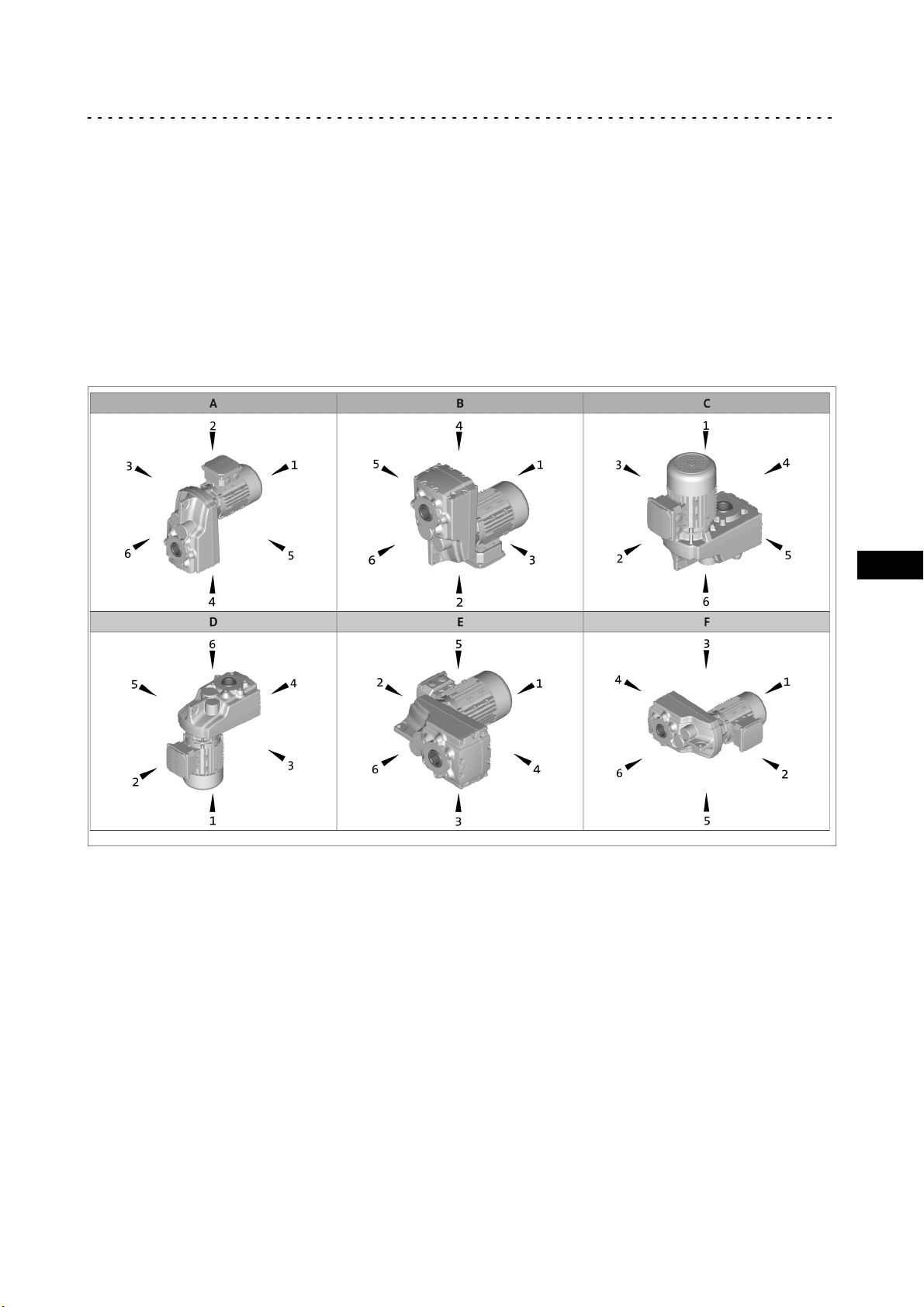
3.2 Identification
Mounting position (A−F) and position of system modules (1−6)
3
Important notes
Hollow shaft: 0 without flange: 0
Solid shaft: 3, 5, 8 (3+5) Flange: 3, 5, 8 (3+5)
Hollow shaft with shrink disc: 3, 5 Terminal box/
Motec:
2, 3, 4, 5
EN
Lenze ¯ MA 12.0013 ¯ 1.0
9
Page 10
3
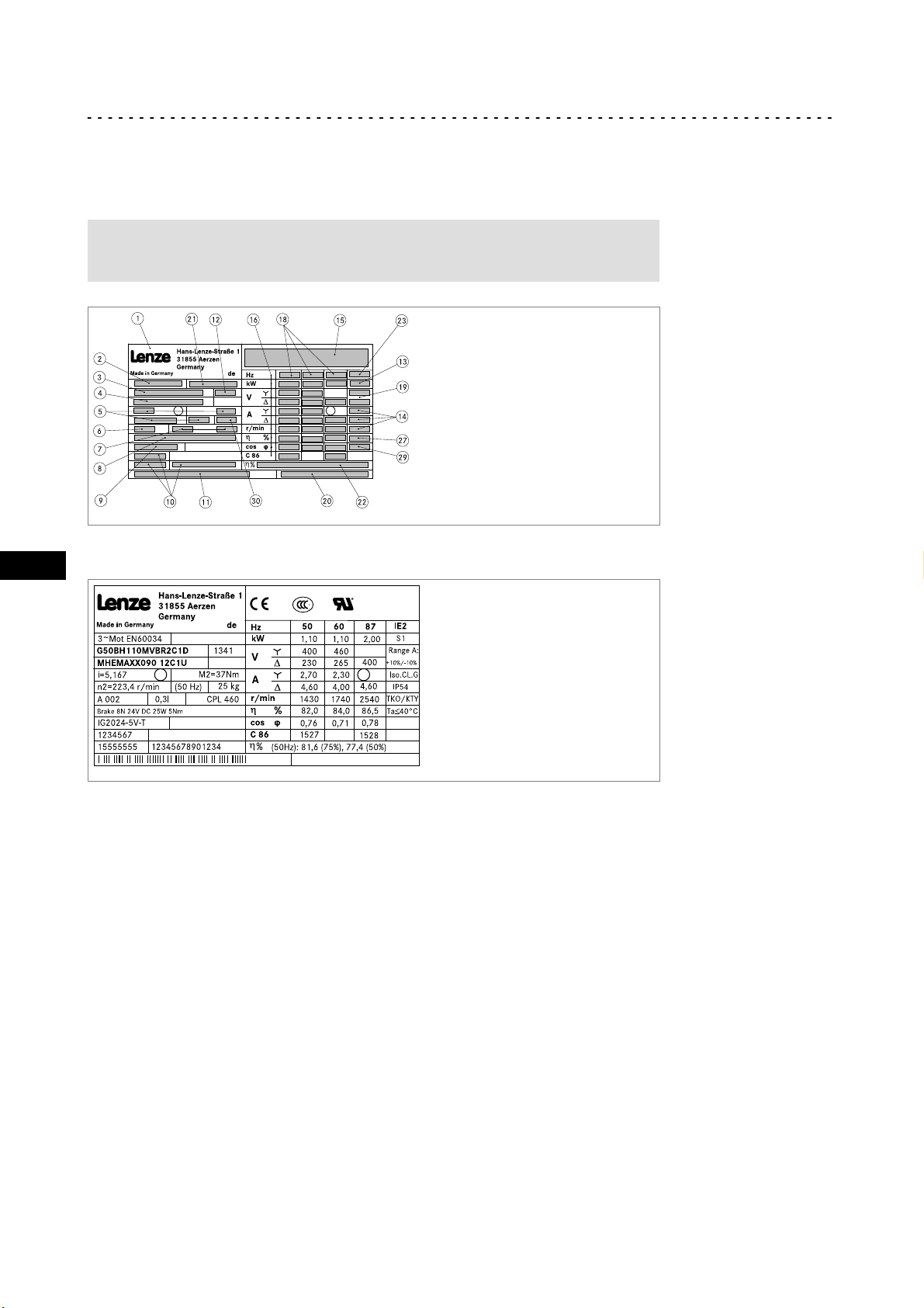
3.2.1 Nameplate
Geared motor
Product description
Identification
Nameplate
Note!
In the geared motor version the nameplate is attached to the motor.
EN
g500−X−001.iso
Example
g500−X−001.iso
10
Lenze ¯ MA 12.0013 ¯ 1.0
Page 11

Pos. Contents
1 Manufacturer / production location
2 Motor type / standard
3 Gearbox type
4 Motor type
5 Technical data
6 Mounting position / position of the system blocks
7 Lubricant amount and type of lubricant
8 Brake data (if fitted)
9 Feedback /pulse encoder or resolver data (if fitted)
10 Manufacture data
11 Bar code
12 Year / week of manufacture
13 Operating mode
14
Temperature class
Enclosure
Motor protection
15 Valid conformities,
approvals and certificates
16 Rated data for
various frequencies
18 Frequencies and corresponding motor data
19
Standard version: Voltage tolerance range "Range A"
UL version: UL file number
20 Additional customer data
21 UL category (e.g. inverter duty motor)
22 Efficiency and part load efficiency
23 Energy efficiency (logo)
27 Permissible ambient temperature range
29 Standstill current (ampere locked rotor ALR)
30 Weight (optional)
Ratio
Rated torque
Rated speed
Rated frequency
Brake
Braking torque
AC/DC brake voltage
Electrical power input
Order number
Material number
Serial number
CE identification
CCC identification
UL mark
UL energy efficiency mark
Hz = frequency
kW = motor power
V = motor voltage
A = motor current
r/min. = motor speed
h = Motor efficiency: at a rated power of
100%
cos j = motor power factor
C 86 = Motor code for controller
parameterisation (code 0086)
Product description
Identification
3
EN
Lenze ¯ MA 12.0013 ¯ 1.0
11
Page 12
EN
3
Product description
Identification
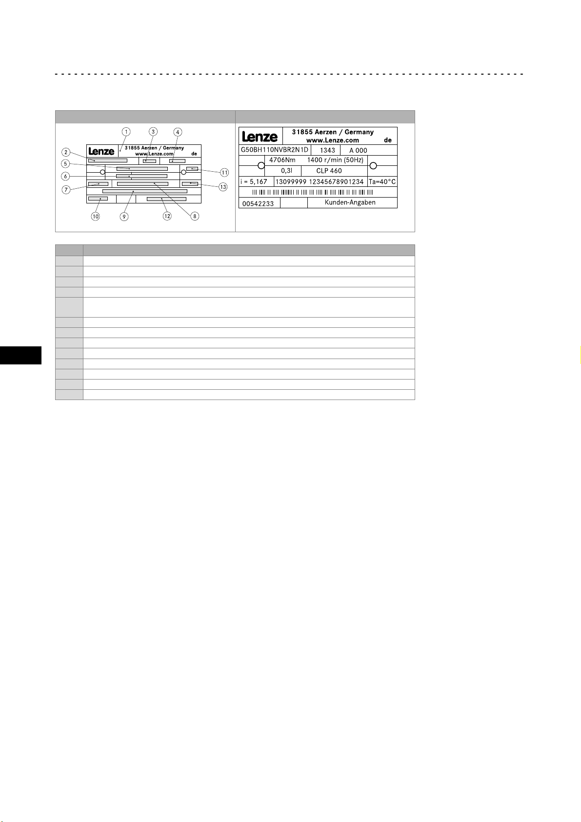
Gearbox
N version Example
Pos. Contents
1 Manufacturer / production location
2 Gearbox and motor type
3 Year / week of manufacture
4 Mounting position / position of the system blocks
5 Rated torque
Rated speed/rated frequency
6 Lubricant amount / type of lubricant
7 Ratio
8 Material number / serial number
9 Bar code
10 Order number
11 Operating factor (indicated when <1.0)
12 Additional customer data
13 Permissible ambient temperature range
G500−X−002.iso
12
Lenze ¯ MA 12.0013 ¯ 1.0
Page 13

Product description
3.3 Transport weights
Motor frame size
063 071 080 090 100 112 132
Gearbox type/size
g500−S130 < 15 < 20 < 25 < 30
g500−S220 < 20 < 20 < 25 < 35 < 35
g500−S400 < 20 < 25 < 30 < 40 < 40
g500−S660 < 25 < 30 < 35 < 45 < 45 < 65 < 95
Tab. 1 Weights in kg
3
Transport weights
EN
Lenze ¯ MA 12.0013 ¯ 1.0
13
Page 14

4
4 Mechanical installation
4.1 Important notes
¯ Use load carrying equipment for transport!
¯ Before the transport
Mechanical installation
Important notes
– check that all components are safely mounted,
– fasten all transport aids (eye bolts or support plates).
Danger!
Danger due to toppling or falling loads!
¯ The payload of the hoists and load handling devices must at least
correspond to the weight of the load.
¯ The load must be secured in such a way that it cannot topple or fall
down.
¯ Do not stay under a pending load!
EN
4.2 Transport equipment for gearbox
Danger!
The motors attached to the gearbox are partially equipped with eyebolts.
These are exclusively determined for mounting/dismounting the motor
to the gearbox and must not be used for the complete geared motor!
g500−S130 ... S660
Fig. 1 Ear of the complete drive system
Stop!
Observe load carrying capacity!
Staying under floating load is prohibited!
14
Lenze ¯ MA 12.0013 ¯ 1.0
Page 15

Mechanical installation
General information about the assembly of drive systems
4.3 Preparation
Note!
Thoroughly remove anticorrosion agents from output shafts and flange
faces.
4.3.1 General information about the assembly of drive systems
Stop!
The lubricant fill quantity of the gearboxes is matched to the mounting
position. The mounting position indicated on the nameplate must be
observed to avoid damage to the gearbox.
4.3.2 Gearboxes with breathers
4
Preparation
Stop!
Do not place gearbox onto breather valve!
No ventilation measures are required for the gearboxes g500−S130 and g500−S220.
Gearboxes which are delivered with a ventilation unit are equipped with a label on the
gearbox.
Remove the transport locking device on the vent valve before the first commissioning.
GT−GNG−13285760.iso/dms
Note!
Loosely enclosed vent valves must be mounted in accordance with the
mounting position, ( LEERER MERKER).
EN
Lenze ¯ MA 12.0013 ¯ 1.0
15
Page 16

4
4.3.3 Condensation drain hole of the motor
Mechanical installation
Preparation
Condensation drain hole of the motor
Note!
Lenze delivers motors with condensation drain holes with sealed
condensation drain holes. The holes are sealed with a plastic plug or a
locking screw. This does not affect the type of protection and the motor is
protected against the ingress of foreign substances during transport and
operation. Further information, ( 36).
EN
16
Lenze ¯ MA 12.0013 ¯ 1.0
Page 17

Mechanical installation
Mounting gearboxes with solid shafts
4.4 Mounting
4.4.1 Mounting gearboxes with solid shafts
¯ Draw the transmission elements onto the output shaft only by using the
centering thread.
Stop!
Shocks and blows to the shafts damage the roller bearings.
4.4.2 Attachment of motors to gearboxes with bearing housing (input design N)
4
Mounting
g500−H_000.iso
Fig. 2 Input side design N
Spider / gear rim 1 Locking screw
Coupling hub 2 Keyway
Drive size
1A 11 23 23 M4 1.5 M3 1.34 * M3 1.34
1B 14 40 25 M5 2.0 M6 10.5 B5 x 5 x 16 M4 2.9
2B 11 23 23 M4 1.5 M3 1.34 * M3 1.34
1C 19 40 25
2C 14 40 25
4C 14 40 25
6C 11 40 25 −−− −−− * −−− −−−
7C 19 40 25
1D 24 60 30
2D 19 60 30 B6 x 6 x 18
1E 28 60 30
2E 24 60 30
3E 19 60 30 B6 x 6 x 18
4E 24 50 50 *
Tab. 2 Attachment of motors to gearboxes with mounting flange
Motor shaft Assembly
D
max. l
[ mm ]
* Use original key for the motor
1)
Key for standard hub and clamping hub
[ mm ]
dimension
M
[ mm ]
Standard hub
Locking screw
Thread
[ mm ]
M5 2.0
M5 2.0
Tightenin
g torque
[ Nm ]
Clamping hub Key
Thread
[ mm ]
Tightenin
g torque
[ Nm ]
M6 10.5
M6 10.5
1)
Clamping ring hub
DIN
6885/1
[ mm ]
B6 x 6 x 16
B5 x 5 x 163C 14 40 25
B6 x 6 x 16 M4 2.9
B8 x 7 x 18
B8 x 7 x 18
Thread
[ mm ]
M4 2.9
M5 6
Tightenin
g torque
[ Nm ]
EN
Lenze ¯ MA 12.0013 ¯ 1.0
17
Page 18

4
4.4.3 Coupling hubs
General
Mechanical installation
Mounting
Coupling hubs
Note!
Standard hubs, clamping hubs and clamping ring hubs are
maintenance−free.We recommend checking the star−shaped spider and
system components when inspecting the drive.
Mounting the standard hub / clamping hub
1. Fit motor key (2).
– Fit enclosed key for drive sizes C, E, F.
2. Push the coupling hub over the motor shaft, mounting dimension m (see Fig. 2
and Tab. 2) must be observed.
EN
3. Secure coupling hub against axial movement using the fixing screw or clamping
screw (1).
4. Lay spider in the coupling claw on the gearbox side.
5. Align claws of the motor−side coupling hub with its counterpart.
6. Slowly push on motor, and bolt on to the gearbox flange.
18
Lenze ¯ MA 12.0013 ¯ 1.0
Page 19

Mounting the clamping ring hub
2
Fig. 3 Coupling
1 Clamping ring hub
2 Clamping ring
3 Clamping screws (DIN912)
Note!
The motor shaft must be designed with fit k6.
Mechanical installation
Mounting
Coupling hubs
1
3
4
1. Grease the contact surfaces of the motor shaft using a thin−bodied oil, e. g.
Castrol 4 in 1" or Klüber Quitsch Ex"!
Stop!
Do not use oil or grease with molybdenum−disulphide or high−pressure
additives, or grease pastes!
2. Push the coupling hub over the motor shaft, mounting dimension m" (see Fig. 2
and Tab. 2) must be observed.
3. Align the hub and tighten the clamping screws until they have contact.
4. Tighten the clamping screws evenly and crosswise with gradually rising torque
until the indicated tightening torque (see Tab. 2) is reached at all clamping screws.
In the intermediate steps, this procedure should also be repeated until the
indicated tightening torque is reached at all clamping screws.
5. Lay spider in the coupling claw on the gearbox side.
6. Align claws of the motor−side coupling hub with its counterpart.
7. Slowly push on motor, and bolt on to the gearbox flange.
EN
Lenze ¯ MA 12.0013 ¯ 1.0
19
Page 20

4
Dismounting the clamping ring hub
1. Loosen the clamping screws evenly one after the other.
Mechanical installation
Mounting
Attachment of gearboxes with hollow shafts and keyway
Stop!
Each screw must only be loosened by half a revolution per pass! Unscrew
all clamping screws by 3 − 4 threads.
2. Remove the screws next to the forcing threads and screw them into the other
threads until they have contact.
3. Tighten the screws in the forcing threads crosswise and step−by−step so that the
clamping ring is loosened.
4. Clean and grease all contact surfaces including threads and head of the clamping
screws before reassembly.
4.4.4 Attachment of gearboxes with hollow shafts and keyway
EN
1. Draw the gearbox with hollow shaft onto the machine shaft to be driven:
– Apply the supplied assembly paste (Fig. 4) on the shaft and in the hollow shaft
bore.
GT−GNG−GKR−011.iso GT−GNG−GKR−011_a.iso
Fig. 4 Application of assembly paste against fretting corrosion (included in the scope of supply)
Stop!
Take up forces only via the hollow shaft, and not via gearbox housing.
2. Secure the gearbox axially:
– The hollow shaft has snap ring grooves for axial securing. Parts used to fix the
shaft are not included in the scope of supply.
20
Lenze ¯ MA 12.0013 ¯ 1.0
Page 21

Mechanical installation
Mounting the shrink disc with a rotating cover
Auxiliary tool (recommended dimensions)
H7
Æ d
25
30
35 M12 7
40
45
Tab. 3 Dimensions in [mm]
Dismounting
1. Undo axial gearbox locking in the hollow shaft.
d
M10
M16
2
4
Mounting
K12.0611
c
7
5
6
8
9
2. Remove/extract the gearbox from the motor shaft using an appropriate auxiliary
tool (Fig. 5).
K12.0611
Fig. 5 Disassembly of gearboxes with hollow shaft, with auxiliary tool
Auxiliary tool (recommended dimensions)
H7
Æ d
25
30
35 12 3
40
45
Tab. 4 Dimensions in [mm]
c
8
10 3
16 4
c
9
4.4.5 Mounting the shrink disc with a rotating cover
EN
Stop!
Do not dismantle new shrink disc.
Never tighten clamping screws before the machine shaft is pushed in.
Otherwise the hollow shaft may be deformed plastically. Protect the
shrink disc against contact while in operation by appropriate measures
(e.g. cover).
Degrease hollow shaft bore and machine shaft!
Lenze ¯ MA 12.0013 ¯ 1.0
21
Page 22

4
4.4.5.1 Mounting the shrink disc
Depending on the design, the shrink discs may be equipped with a rotating cover
(protective cap, pos. 1).
Mechanical installation
Mounting
Mounting the shrink disc
Note!
This cover is fitted to the shrink disc on delivery.
2
1
5.
1.
EN
1
Fig. 6
1 Protection cover
2 Clamping screws
1. Remove protective cap (1), if available.
2
2. Check machine shaft
– Diameter in fit tolerance h6
– Surface roughness R
3. Thoroughly clean and degrease hollow shaft bore and machine shaft.
Note!
Thoroughly degrease the bore over the entire hollow shaft length to
make sure that remainders of the anticorrosion agent will not be carried
off into the area of the shrink disc when pushing on the machine shaft.
4. Slightly loosen clamping screws (2) one after the other, do not unscrew!
5. Push drive onto machine shaft.
6. Slightly tighten clamping screws manually.
7. Tighten clamping screws (2) one after the other (see Fig. 7) in several passes, with
rising torque, evenly until the indicated screw−tightening torque (see Tab. 5 ) is
reached at all screws.
£ 15 mm
z
KL_GFL06_001−dms
22
GT−GNG−003.iso/dms
Lenze ¯ MA 12.0013 ¯ 1.0
Page 23

Mechanical installation
Mounting the shrink disc
Fig. 7 Explanation: "one after the other"
Tip!
Several (in general more than 5 ) passes are necessary until the full
tightening torque is reached at all screws!
The shrink disc is mounted correctly and fixed when the faces of the outer ring and the
inner ring are aligned (Fig. 8). Minimum misalignments are permissible.
4
Mounting
GT−GNG−001.iso
Fig. 8 Hollow shaft with shrink disk
3 Outer ring
4 Inner ring
Hollow shaft bore [mm] 20 25 30 35 40 50 60 65 80 100
Torque [ Nm ] 12 30 30 30 30 30 59 70 59 100
Tab. 5 Tightening torque for the clamping screws
free of grease
Note!
If a different tightening torque is indicated on the shrink disc, this
tightening torque has priority over the value indicated in the table.
8. Push protective cap (1, LEERER MERKER) onto the shrink disc.
Tip!
For finding out the cause of non−reached torques of the shrink disc
connection, please go through the troubleshooting list in chapter 8.
EN
Lenze ¯ MA 12.0013 ¯ 1.0
23
Page 24

4
Dismounting
Mechanical installation
Mounting
Mounting the shrink disc
Danger!
Loose drive components or drive components falling down may cause
injury to persons or damage to the machine. Secure the drive
components before disassembly.
1. Remove protective cap (1).
2. Loosen clamping screws (2) evenly one after the other each by ¼ revolution in
several passes. Do not unscrew clamping screws completely to prevent accidents!
3. Press off outer ring (see Fig. 8), if necessary. For this, loosen the outer ring using
the forcing threads and some clamping screws (number corresponding to the
forcing threads in the inner ring). For loosening the outer ring, screw in the screws
evenly to prevent canting. Press off the outer ring until loosened completely.
4. Remove the drive from the machine shaft.
EN
Stop!
Dismantle the shrink disc only for cleaning purposes. Afterwards, grease
bevel surfaces and screws using a solid lubricant with a friction factor of
m = 0.04.
¯ Suitable lubricants on molybdenum−disulphide lubricant (MoS2) basis are, e.g.:
– Molykote G Rapid (company Dow Corning)
– Molykote BR2 Plus (company Dow Corning)
– Molykombin UMFT1 (company Klüber Lubrication)
Usually, disassembly problems only occur if:
¯ the connection is spinning due to overload or a too low friction factor and fretting
corrosion has occurred,
¯ the shrink disc has been tightened too much leading to a plastic deformation of
components,
¯ the components are corroded.
24
Lenze ¯ MA 12.0013 ¯ 1.0
Page 25

4.4.6 Mounting the fixed cover
Note!
This cover is supplied loose on delivery!
Mechanical installation
Mounting
Mounting the fixed cover
X
X
4
Clip the protection cover into the bores, 6 x flange side, 4 x motor side.
4.4.7 Foot mounting
The foot on the g500−S130 S660 gearboxes can be mounted in three positions (3, 4,
5) using the supplied screws. It is mounted on side 6 using 4 screws and additionally on
side 1 using 2 screws. The screws must be mounted according to the hole pattern on the
foot (see figure) depending on the foot position.
Mounting order: depending on the mounting situation and installation space, the foot
can first be screwed to the machine housing and then to the gearbox or vice versa. The
foot can be mounted to the machine using studs or screws (not included in the scope of
supply).
EN
Aligning the gearbox with the foot: independent of the mounting order, the gearbox
must be aligned with the machine shaft.
Gearbox type / size Tightening torque
[ Nm ]
g500−S130 + g500−S220 10.1
g500−S400 + g500−S660 48
Lenze ¯ MA 12.0013 ¯ 1.0
25
Page 26

Electrical installation5
5 Electrical installation
Danger!
Electrical connections must only be carried out by skilled personnel!
EN
26
Lenze ¯ MA 12.0013 ¯ 1.0
Page 27

Commissioning and operation
6 Commissioning and operation
6.1 Important notes
Stop!
The drive may only be commissioned by skilled personnel!
¯ Take safety measures prior to any operation:
– Disconnect the machine from the mains, ensure standstill of the drive system
and avoid any machine movement.
6.2 Before switching on
Please check:
¯ Drive function - machine function assignment
¯ The direction of rotation of the drive shaft
6
Important notes
g500−S 2−stage g500−S 3−stage
¯ Does the drive appear undamaged?
¯ Is the mechanical fixing o.k.?
¯ Is the electrical connection correct?
¯ Are all rotating parts and surfaces that may become hot protected against
contact?
¯ For gearboxes with breathing:
– Has the transport locking device been removed?
EN
Lenze ¯ MA 12.0013 ¯ 1.0
27
Page 28

6
6.3 During operation
During operation, check the drive periodically and take special care of:
¯ changes compared to normal operation, like
¯ In case of faults:
If the fault cannot be remedied, please contact the Lenze customer service.
Commissioning and operation
During operation
– unusual noise, stronger vibrations or increased temperatures,
– leakages,
– loose fixing elements,
– the condition of the electrical cables.
– shut down the drive,
– check the troubleshooting table.
EN
28
Lenze ¯ MA 12.0013 ¯ 1.0
Page 29

7 Maintenance
7.1 Important notes
Note!
¯ Gearboxes below 200 Nm are lubricated for life.
¯ The mechanical power transmission system is maintenance−free.
7.2 Maintenance intervals
¯ In case of gearboxes > 200 Nm, the lubricant must regularly be replaced.
– The type of lubricant is indicated on the nameplate. Replace the lubricant only
with the same type of lubricant.
– The lubricant maintenance interval depends on the lubricant temperature, see
Fig. 9.
Maintenance
Important notes
7
Stop!
With drive systems: observe the maintenance intervals for the other drive
components!
100
90
80
0
70
1000
1
Fig. 9 Lubricant diagram
Oil sump temperature [°C]
Oil life/changing intervals [operating
hours h]
7.3 Maintenance operations
3
16000 h
10000
2
25000 h
Synthetic oil CLP HC/CLP PG
Mineral oil CLP
EN
100000
GT−GNG−002.iso/dms
Gearboxes and geared motors are ready to use on delivery and filled by Lenze with the
lubricant type and lubricant quantity indicated on the nameplate. The first filling
corresponds to the mounting position and design indicated on the nameplate.
Lenze ¯ MA 12.0013 ¯ 1.0
29
Page 30

7
Breather position, oil filling screw and drain plug
A B
Maintenance
Maintenance operations
S400
+
+
S220
+
+
S130
EN
S130
C D
+
+
S400+S660
S400+S660
S130
+
S220
E F
+
S220
+
+
S130
30
+
S130
+
S130
Filler Drain
Breather element Check
Lenze ¯ MA 12.0013 ¯ 1.0
Page 31

Maintenance
Maintenance operations
Oil−level inspection
Check the oil level by means of the displayed dipsticks. Manufacture them according to
the mounting position.
Model: Dipsticks for g500−S130
7
A, C, F
D
B
EN
E
Lenze ¯ MA 12.0013 ¯ 1.0
31
Page 32

7
Model: Dipsticks for g500−S220
Maintenance
Maintenance operations
EN
A
B
C
32
D
E
F
Lenze ¯ MA 12.0013 ¯ 1.0
Page 33

Model: Dipsticks for g500−S400
A
B
Maintenance
Maintenance operations
C
7
D
EN
F
E
Lenze ¯ MA 12.0013 ¯ 1.0
33
Page 34

7
Model: Dipsticks for g500−S660
Maintenance
Maintenance operations
EN
A, E
C
B
F
D
34
Lenze ¯ MA 12.0013 ¯ 1.0
Page 35

Maintenance
Maintenance operations
Changing lubricant
Stop!
¯ Gearbox should be warm.
¯ Secure drive system and machine from inadvertent movement and
mains connection.
The type of lubricant indicated on the nameplate by the following manufacturers is
approved.
Shell Klüber Fuchs
1. Place receptacle under oil drain plug.
7
2. Remove breathing / oil filler plug.
3. Completely drain lubricant by removing the oil drain plug.
4. Reinsert drain plug (if necessary, replace seal).
5. Fill in lubricant through filler hole (quantities see nameplate).
6. Screw in breathing / oil filler plug.
7. Dispose of waste oil according to the applicable regulations.
EN
Lenze ¯ MA 12.0013 ¯ 1.0
35
Page 36

7
7.3.1 Motors
Drain condensation
Depending on the mounting position, the condensation drain holes are always at the
bottom of the motor!
¯ For condensate drainage
Maintenance
Repair
Motors
– the motor must be deenergised;
– the plugs (screws) must be removed.
Stop!
To restore the enclosure, re−insert the plugs (screws) after condensate
drainage. If the condensation drain holes are not sealed again, the IP
enclosure of the motor will be reduced. For horinzontal motor shafts to
IP23 and for vertical motor shafts to IP20.
EN
Fig. 10 Motor with condensation drain holes
Condensation drain holes
7.4 Repair
¯ We recommend that all repairs are carried out by the Lenze customer service.
36
Lenze ¯ MA 12.0013 ¯ 1.0
Page 37

Maintenance
7.5 Disposal
Protect the environment! Packing material can be recycled. Dispose of your separated
resources according to the waste disposal regulations or via a waste management
company.
The following table provides recommendations for an environmentally friendly
disposal of the machine and its components.
What? Where?
Transport
material
Lubricants Oil, grease
Components Housing:
Pallets Return to the manufacturer or
Packaging material Cardboard box to waste paper
Detergents and solvents
Paint residues
Cast iron, aluminium,
Bearings, gear wheel shafts:
Seals, electronic scrap
copper
Steel
Hazardous waste
forwarder
Plastics to plastics recycling or
residual waste
Reuse or dispose of wood wool
Dispose according to current
regulations
Separate valuable substances
and dispose
7
Disposal
EN
Lenze ¯ MA 12.0013 ¯ 1.0
37
Page 38

EN
Troubleshooting and fault elimination8
8 Troubleshooting and fault elimination
If any malfunctions should occur during operation of the drive system, please check the
possible causes using the following table. If the fault cannot be eliminated by one of the
listed measures, please contact the Lenze Service.
Fault Possible cause Remedy
Drive does not turn
Motor runs, gearbox does
not
Unusual running noises
Excessive temperature
Loose fixing elements Vibrations Avoid vibrations
Shrink disc connection is
spinning
Voltage supply interrupted Check connection
Faulty electrical connection Check that supply voltage
Excessive load Reduce load
Coupling components are missing or
defective
Gearbox is defective Inform Lenze Service
Clutch disengaged Engage the clutch
Overload Reduce load
Damage to the gearbox or motor Inform Lenze Service
Overload Reduce load
Inadequate heat dissipation Improve cooling air flow
Lack of lubricant Top up lubricant according to
¯ Correct screw tightening torque has not
been reached
– Insufficient number of passes, not all
screws are tightened correctly.
¯ Machine shaft and hollow shaft bore
not sufficiently degreased
¯ Wrong component part dimensions
– Fits, roughnesses
¯ Yield point of machine shaft material is
too low
– Re > 300 N/mm2 required
¯ Friction factors are too low
– Coefficients of friction m ³ 0.15
required
¯ The shrink disc itself has been
degreased so that the screws and the
bevels are dry. Due to incorrect friction
factors, the shrink disc cannot be
tightened correctly.
matches nameplate data
Check drive−machine
assignment
Check mounting
Check drive−machine
assignment
Check drive−machine
assignment
Clean gearbox / motor
regulations
Specifications for assembly,
dimensions and material not
observed
38
Lenze ¯ MA 12.0013 ¯ 1.0
Page 39

Notes !
EN
Lenze ¯ MA 12.0013 ¯ 1.0
39
Page 40

© 12/2013 | MA 12.0013 | .NjO | 1.0 | TD09
Lenze Drives GmbH
Postfach 10 13 52
D−31763 Hameln
Germany
+49515482−0
+49515482−2800
Lenze@Lenze.com
www.Lenze.com
Lenze Service GmbH
Breslauer Straße 3
D−32699 Extertal
Germany
0080002446877 (24 h helpline)
+49515482−1396
Service@Lenze.com
10987654321
 Loading...