

Page 1

g500
G50AB045 ... G50BB320 |
45 Nm ... 20000 Nm
Bevel gearbox / Bevel gearbox
with three−phase AC motor
Mounting Instructions
EN
.Xqô
Ä.Xqôä
l
Page 2

, Please read these instructions before you start working!
Follow the enclosed safety instructions.
0Abb. 0Tab. 0
Page 3

Contents i
1 About this documentation 5. . . . . . . . . . . . . . . . . . . . . . . . . . . . . . . . . . . . . . . . . . . . . . . . . . . . . .
1.1 Document history 6. . . . . . . . . . . . . . . . . . . . . . . . . . . . . . . . . . . . . . . . . . . . . . . . . . . . .
1.2 Conventions used 6. . . . . . . . . . . . . . . . . . . . . . . . . . . . . . . . . . . . . . . . . . . . . . . . . . . . . .
1.3 Terminology used 6. . . . . . . . . . . . . . . . . . . . . . . . . . . . . . . . . . . . . . . . . . . . . . . . . . . . .
1.4 Notes used 7. . . . . . . . . . . . . . . . . . . . . . . . . . . . . . . . . . . . . . . . . . . . . . . . . . . . . . . . . . .
2 Safety instructions 8. . . . . . . . . . . . . . . . . . . . . . . . . . . . . . . . . . . . . . . . . . . . . . . . . . . . . . . . . . . . .
2.1 General safety instructions for drive components 8. . . . . . . . . . . . . . . . . . . . . . . . . . .
2.2 Application as directed 12. . . . . . . . . . . . . . . . . . . . . . . . . . . . . . . . . . . . . . . . . . . . . . . .
2.3 Foreseeable misuse 13. . . . . . . . . . . . . . . . . . . . . . . . . . . . . . . . . . . . . . . . . . . . . . . . . . . .
2.4 Residual hazards 14. . . . . . . . . . . . . . . . . . . . . . . . . . . . . . . . . . . . . . . . . . . . . . . . . . . . . .
3 Product description 15. . . . . . . . . . . . . . . . . . . . . . . . . . . . . . . . . . . . . . . . . . . . . . . . . . . . . . . . . . . . .
3.1 Important notes 15. . . . . . . . . . . . . . . . . . . . . . . . . . . . . . . . . . . . . . . . . . . . . . . . . . . . . . .
3.2 Identification 16. . . . . . . . . . . . . . . . . . . . . . . . . . . . . . . . . . . . . . . . . . . . . . . . . . . . . . . . .
3.2.1 Nameplate 16. . . . . . . . . . . . . . . . . . . . . . . . . . . . . . . . . . . . . . . . . . . . . . . . . . .
3.2.2 Gearbox code 18. . . . . . . . . . . . . . . . . . . . . . . . . . . . . . . . . . . . . . . . . . . . . . . . .
4 Mechanical installation 19. . . . . . . . . . . . . . . . . . . . . . . . . . . . . . . . . . . . . . . . . . . . . . . . . . . . . . . . .
4.1 Important notes 19. . . . . . . . . . . . . . . . . . . . . . . . . . . . . . . . . . . . . . . . . . . . . . . . . . . . . . .
4.2 Transport 19. . . . . . . . . . . . . . . . . . . . . . . . . . . . . . . . . . . . . . . . . . . . . . . . . . . . . . . . . . . .
4.3 Preparation 21. . . . . . . . . . . . . . . . . . . . . . . . . . . . . . . . . . . . . . . . . . . . . . . . . . . . . . . . . . .
4.3.1 General information about the assembly of drive systems 22. . . . . . . . . . .
4.3.2 Gearboxes with breathers 23. . . . . . . . . . . . . . . . . . . . . . . . . . . . . . . . . . . . . .
4.3.3 Gearbox with compensation container
(preferably for mounting pos. "C") 24. . . . . . . . . . . . . . . . . . . . . . . . . . . . . . .
4.3.4 Mounting the gearboxes 25. . . . . . . . . . . . . . . . . . . . . . . . . . . . . . . . . . . . . . .
4.3.5 Maximum permissible load at the motor adapter 26. . . . . . . . . . . . . . . . . .
4.3.6 Mounting of motors to gearboxes with an adapter and a
flexible coupling 28. . . . . . . . . . . . . . . . . . . . . . . . . . . . . . . . . . . . . . . . . . . . . .
4.3.7 Coupling hubs 30. . . . . . . . . . . . . . . . . . . . . . . . . . . . . . . . . . . . . . . . . . . . . . . .
4.3.8 Mounting of motors to gearboxes with a short adapter with a
plug−in hollow shaft with a keyway (drive−end version B or H) 33. . . . . . . .
4.3.9 Attachment of gearboxes with hollow shafts and keyway 34. . . . . . . . . . .
4.3.10 Mounting the shrink disc with a rotating cover 38. . . . . . . . . . . . . . . . . . . .
4.3.11 Mounting the fixed cover 41. . . . . . . . . . . . . . . . . . . . . . . . . . . . . . . . . . . . . . .
4.3.12 Mounting the hoseproof hollow shaft cover 42. . . . . . . . . . . . . . . . . . . . . .
4.3.13 Torque plate assembly 43. . . . . . . . . . . . . . . . . . . . . . . . . . . . . . . . . . . . . . . . .
5 Electrical installation 44. . . . . . . . . . . . . . . . . . . . . . . . . . . . . . . . . . . . . . . . . . . . . . . . . . . . . . . . . . .
5.1 Motor connection 44. . . . . . . . . . . . . . . . . . . . . . . . . . . . . . . . . . . . . . . . . . . . . . . . . . . . .
5.2 Motor options 44. . . . . . . . . . . . . . . . . . . . . . . . . . . . . . . . . . . . . . . . . . . . . . . . . . . . . . . .
Lenze ¯ MA 12.0014 ¯ 5.1
3
Page 4

Contentsi
6 Commissioning and operation 45. . . . . . . . . . . . . . . . . . . . . . . . . . . . . . . . . . . . . . . . . . . . . . . . . . .
6.1 Important notes 45. . . . . . . . . . . . . . . . . . . . . . . . . . . . . . . . . . . . . . . . . . . . . . . . . . . . . . .
6.2 Before switching on 45. . . . . . . . . . . . . . . . . . . . . . . . . . . . . . . . . . . . . . . . . . . . . . . . . . .
6.3 Initial commissioning 45. . . . . . . . . . . . . . . . . . . . . . . . . . . . . . . . . . . . . . . . . . . . . . . . . .
6.4 During operation 46. . . . . . . . . . . . . . . . . . . . . . . . . . . . . . . . . . . . . . . . . . . . . . . . . . . . . .
7 Maintenance 47. . . . . . . . . . . . . . . . . . . . . . . . . . . . . . . . . . . . . . . . . . . . . . . . . . . . . . . . . . . . . . . . . .
7.1 Important notes 47. . . . . . . . . . . . . . . . . . . . . . . . . . . . . . . . . . . . . . . . . . . . . . . . . . . . . . .
7.2 Maintenance intervals 47. . . . . . . . . . . . . . . . . . . . . . . . . . . . . . . . . . . . . . . . . . . . . . . . . .
7.3 Maintenance operations 49. . . . . . . . . . . . . . . . . . . . . . . . . . . . . . . . . . . . . . . . . . . . . . . .
7.3.1 Position of the lubricant monitoring elements 50. . . . . . . . . . . . . . . . . . . .
7.3.2 Table of lubricants 58. . . . . . . . . . . . . . . . . . . . . . . . . . . . . . . . . . . . . . . . . . . .
7.3.3 Checking the oil level 59. . . . . . . . . . . . . . . . . . . . . . . . . . . . . . . . . . . . . . . . . .
7.3.4 Changing the oil 62. . . . . . . . . . . . . . . . . . . . . . . . . . . . . . . . . . . . . . . . . . . . . .
7.3.5 Lubricate roller bearings 63. . . . . . . . . . . . . . . . . . . . . . . . . . . . . . . . . . . . . . .
7.3.6 Drain condensation 64. . . . . . . . . . . . . . . . . . . . . . . . . . . . . . . . . . . . . . . . . . .
7.4 Repair 65. . . . . . . . . . . . . . . . . . . . . . . . . . . . . . . . . . . . . . . . . . . . . . . . . . . . . . . . . . . . . . .
8 Troubleshooting and fault elimination 66. . . . . . . . . . . . . . . . . . . . . . . . . . . . . . . . . . . . . . . . . . . .
4
Lenze ¯ MA 12.0014 ¯ 5.1
Page 5

About this documentation 1
1 About this documentation
Contents
¯ This documentation serves for safety−relevant operations on and with the
gearboxes. It contains safety instructions which must be observed.
¯ All personnel working on and with the gearboxes must have the documentation
available during the work and observe the information and notes relevant for
them.
¯ The documentation must always be complete and in a perfectly readable state.
¯ The information in this documentation can be supplemented by further
documents, if necessary, e.g. information regarding the motors mounted,
additional components on the gearbox or motor, or with regard to gearboxes and
motors in ATEX design.
Target group
This documentation is directed at qualified skilled personnel according to IEC 60364.
Qualified skilled personnel are persons who have the required qualifications to carry out
all activities involved in installing, mounting, commissioning, and operating the
product.
I Tip!
Information and tools concerning the Lenze products can be found in the
download area at
www.lenze.com
Lenze ¯ MA 12.0014 ¯ 5.1
5
Page 6

1
About this documentation
Document history
1.1 Document history
Material number Version Description
13457390 1.0 02/2014 TD29 First edition for the pilot series
.Xqô 5.1 09/2018 TD29 "Maintenance" chapter: g500−B240 − lubricated for
.Xqô 5.1 09/2018 TD29 Complete revision including the cast iron gearboxes
13535365 4.0 05/2017 TD09 Drawing exchanged in the chapter "Disassembly of
13553160
.Xqô 5.1 09/2018 TD29 Error corrections
5.0 06/2018 TD15 Array of products extended
life
Table new: load carrying capacity of the eye bolt
gearbox with hollow shaft"
Auxiliary tool table supplemented
Important note corrected in the Maintenance
chapter
Ambient temperatures changed in the lubricant
table
1.2 Conventions used
This documentation uses the following conventions to distinguish different types of
information:
Type of information Writing Example/notes
Numeric notation
Decimal Standard notation Example: 1234
Decimal separator Point The decimal point is always used.
Icons
Page reference
Documentation reference
Wildcard
^
,
L
For example: 1234.56
Reference to another page with additional
information
For instance:
Reference to another documentation with
additional information
Example:
Wildcard for options, selection data
^ 16 = see page 16
, EDKxxx = see EDKxxx documentation
1.3 Terminology used
Term In the following text used for
Gearboxes Gearboxes of the g500 product family
Drive system Drive systems with g500 gearboxes and other Lenze drive
components
6
Lenze ¯ MA 12.0014 ¯ 5.1
Page 7

About this documentation
1.4 Notes used
The following pictographs and signal words are used in this documentation to indicate
dangers and important information:
Safety instructions
Layout of the safety instructions:
} Danger!
(characterises the type and severity of danger)
Note
(describes the danger and gives information about how to prevent
dangerous situations)
Pictograph and signal word Meaning
Danger of personal injury through dangerous electrical
voltage
{ Danger!
} Danger!
( Stop!
Reference to an imminent danger that may result in death
or serious personal injury if the corresponding measures are
not taken.
Danger of personal injury through a general source of
danger
Reference to an imminent danger that may result in death
or serious personal injury if the corresponding measures are
not taken.
Danger of property damage
Reference to a possible danger that may result in property
damage if the corresponding measures are not taken.
1
Notes used
Application notes
Pictograph and signal word Meaning
) Note!
I Tip!
,
Important note to ensure trouble−free operation
Useful tip for easy handling
Reference to another document
Lenze ¯ MA 12.0014 ¯ 5.1
7
Page 8

2
2 Safety instructions
2.1 General safety instructions for drive components
(in compliance with Low−Voltage Directive 2014/35/EU)
At the time of dispatch, the drive components are in line with the latest state of the art
and can be regarded as operationally safe.
Scope
The following general safety instructions apply to all Lenze drive and automation
components.
The product−specific safety and application notes given in this documentation must be
observed!
General hazards
Safety instructions
General safety instructions for drive components
} Danger!
Disregarding the following basic safety measures may lead to severe
personal injury and damage to material assets!
¯ Lenze drive and automation components ...
... must only be used for the intended purpose.
... must never be operated if damaged.
... must never be subjected to technical modifications.
... must never be operated unless completely assembled.
... must never be operated without the covers/guards.
... can − depending on their degree of protection − have live, movable or rotating parts
during or after operation. Surfaces can be hot.
... must not be actuated if the drive system shows vibration accelerations > 2g
(20m/s
... must not be actuated in the resonance range of a system or the Lenze drive system.
¯ All specifications of the corresponding enclosed documentation must be
observed.
This is vital for safe and trouble−free operation and for achieving the specified
product features.
¯ Only qualified skilled personnel are permitted to work with or on Lenze drive and
automation components.
According to IEC 60364 or CENELEC HD 384, these are persons ...
... who are familiar with the installation, assembly, commissioning and operation of
the product,
... possess the appropriate qualifications for their work,
... and are acquainted with and can apply all the accident prevent regulations,
directives and laws applicable at the place of use.
2
).
8
Lenze ¯ MA 12.0014 ¯ 5.1
Page 9

Safety instructions
General safety instructions for drive components
Temperatures
The permissible temperature range is determined by the following:
¯ The lubricant specifications in connection with the expected oil temperatures in
operation (see chapter 7.2 and nameplate).
¯ The thermal class of the motor considering the motor temperature expected
during operation (see nameplate and/or operating instructions of the motor).
¯ Protect geared motors against direct solar radiation. Avoid heat concentration
beneath covers.
The operating temperature is determined by the power loss, the ambient temperature
and the cooling system!
( Stop!
With mineral oil, the upper temperature limit for continuous operation is
80°C, with synthetic oil and shaft sealing rings made of FP (Viton) it is
100°C. If these temperatures are exceeded, measures are necessary to
reduce the temperature, (¶ 66).
2
} Danger!
Depending on the operating conditions, surfaces may be hot, provide
protection against accidental contact.
Ambient media
¯ Gearboxes are protected against dust and spray water.
¯ Motors according to their enclosure (see nameplate and/or operating instructions
for the motor).
¯ Ambient media − especially chemically aggressive − can destroy shaft seals and
coatings (plastic). Abrasive media endanger shaft seals.
¯ The installation site of the drive must be free of shocks and vibration.
¯ Protect geared motors against direct solar radiation. Avoid heat concentration
beneath covers.
¯ Dirt of dust deposits impede the heat dissipation (cooling).
Transport
Before transport
¯ check that all component parts are safely mounted;
¯ check that all component parts with a loose fastening are secured or removed;
¯ tighten all transport aids (eye bolts or support plates).
Use an appropriate means of transport and lifting equipment! (¶ 19)
Lenze ¯ MA 12.0014 ¯ 5.1
9
Page 10

2
Storage
If you do not install the gearbox immediately, provide for proper storage conditions.
¯ Generally
¯ Up to one year:
Safety instructions
General safety instructions for drive components
– Store gearboxes indoors in a dry, clean (low−dust) and sunlight−protected
environment.
– The storage location must be free from vibrations and shocks (V
in order to prevent roller bearing standstill damage.
– Temperature changes with condensate formation are to be avoided.
– Do not activate ventilation unit, in order to prevent air exchange with the
ambient air.
– Store gearboxes with a ventilation unit with the vent plug on top.
– Shafts and uncoated surfaces are delivered in a protected against rust status.
Aftertreatment is required where the corrosion protection has been damaged.
– Remove the plug for motors with condensation drain holes (option)(¶ 21).
< 0.2 mm/s)
eff
¯ More than one year, up to two years:
– Apply a long−term corrosion preventive (e.g. Anticorit BW 366 from the Fuchs
company) to the shafts and uncoated surfaces before storing the motor away.
– Install gearbox in mounting position A.
– Fill gearbox up to the top vent hole / oil hole with the oil grade specified (see
nameplate). Then mount the locking screw and ventilation unit (do not activate)
again.
Corrosion protection
Lenze offers paints with different resistance characteristics for drive systems. Since the
resistance may be reduced when the paint coat is damaged, defects in paint work (e.g.
through transport or assembly) must be removed professionally to reach the required
corrosion resistance.
) Note!
Increased surface and corrosion protection can be achieved by using
adapted coating systems.
Mechanical installation
¯ Provide for careful handling and avoid mechanical overload. During handling
neither bend components, nor change the insulation distances.
10
Lenze ¯ MA 12.0014 ¯ 5.1
Page 11

Safety instructions
General safety instructions for drive components
Electrical installation
¯ Carry out the electrical installation according to the relevant regulations (e. g.
cable cross−sections, fusing, connection to the PE conductor). Additional notes are
included in the documentation.
¯ The Instructions contain notes concerning wiring according to EMC regulations
(shielding, earthing, filters and cable routing). The compliance with limit values
required by the EMC legislation is the responsibility of the manufacturer of the
machine or system.
Warning: The inverters are automation components which can be used in industrial
environment according to EN 61000−6−4. These products may cause radio
interference in residential areas. If this happens, the operator may need to take
appropriate action.
¯ Only plug in or remove pluggable terminals in the deenergised state!
Commissioning
¯ If required, you have to equip the system with additional monitoring and
protective devices in accordance with the respective valid safety regulations (e. g.
law on technical equipment, regulations for the prevention of accidents).
2
¯ Before commissioning remove transport locking devices and keep them for later
transports.
Geared motors for deep−freeze applications
¯ Geared motors for deep−freeze applications are specially optimised to operation
at very low temperatures. Observe that for operation outside the temperature
range specified (e.g. during commissioning) increased wear or even failures may
occur.
¯ We recommend loading the gearbox with a maximum of 50 % of the rated output
torque if it is outside the specified temperature range during commissioning.
Disposal
Sort individual parts according to their properties. Dispose of them as specified by the
current national regulations.
Lenze ¯ MA 12.0014 ¯ 5.1
11
Page 12

2
2.2 Application as directed
All products which this documentation applies to are no household appliances but are
exclusively intended as components for re−utilisation for commercial use or
professional use in terms of IEC/EN 61000−3−2. They meet the requirements of the
Low−Voltage Directive 2014/35/EU and the requirements of the harmonised standards
of the IEC/EN 60034 series.
Only use the products under the operating conditions and power limits specified in this
documentation.
Do not use the brakes installed as fail−safe brakes. It cannot be ruled out that the braking
torque is reduced by disruptive factors which cannot be influenced.
¯ Drives
Any other use shall be deemed inappropriate!
Safety instructions
Application as directed
– ... must only be operated under the operating conditions and power limits
specified in this documentation.
– ... comply with the protection requirements of the EU Low−Voltage Directive.
12
Lenze ¯ MA 12.0014 ¯ 5.1
Page 13

2.3 Foreseeable misuse
Impermissible applications:
¯ In a potentially explosive atmosphere
– Exception: special ATEX design
¯ In aggressive environments (acids, gases, vapours, dusts, or oils).
¯ Under water or in liquids
¯ Under radiation
Safety instructions
Foreseeable misuse
2
Lenze ¯ MA 12.0014 ¯ 5.1
13
Page 14

2
2.4 Residual hazards
Protection of persons
¯ Risk of burns!
Safety instructions
Residual hazards
– Hot surfaces up to 140 °C during operation! Provide protection against contact.
¯ Highfrequency voltages can be capacitively transferred to the motor housing
through the inverter supply.
– Earth motor housing carefully.
¯ Risk of injury due to rotating shaft!
– Before working on the drive system, ensure that the motor is at a standstill.
¯ Danger of unintentional starting or electrical shocks!
– Connections must only be made when the equipment is deenergised and the
motor is at standstill.
– Installed brakes are no fail−safe brakes.
¯ Dangerous voltages at the power terminals, even if the plug is removed: residual
voltage >60 V!
Motor protection
¯ Installed thermal detectors are no full protection for the machine.
– If required, limit the maximum current, parameterise the controller such that it
will be switched off after some seconds of operation with I > I
there is the danger of blocking.
, especially if
N
– Installed overload protection does not prevent an overload under any
conditions.
¯ Installed brakes are no fail−safe brakes.
– The torque can be reduced due to disruptive factors that cannot be influenced,
e.g. by ingressing oil due to a defect shaft sealing ring on the A side.
¯ Fuses are no motor protection.
– Use current−dependent motor protection switches at average operating
frequency.
– Use installed thermal detectors at high operating frequency.
¯ In the case of permanent−magnet motors, too high torques cause
demagnetisation.
– The maximum torques according to catalogue must not be exceeded.
¯ If deviations from normal operation occur, e.g. increased temperature, noise,
vibration, determine the cause and, if necessary, contact the manufacturer. If in
doubt, switch off the motor.
¯ Design with plug:
– Never disconnect plug when energised! Otherwise, the plug can be destroyed.
– Switch off power supply and inhibit controller prior to disconnecting the plug.
Fire protection
¯ Fire hazard
– Prevent contact with flammable substances.
14
Lenze ¯ MA 12.0014 ¯ 5.1
Page 15

3 Product description
3.1 Important notes
¯ The most important technical data is given on the nameplate.
¯ The product catalogues contain further technical data.
Product description
Important notes
3
Lenze ¯ MA 12.0014 ¯ 5.1
15
Page 16
3
Product description
Identification
Nameplate
3.2 Identification
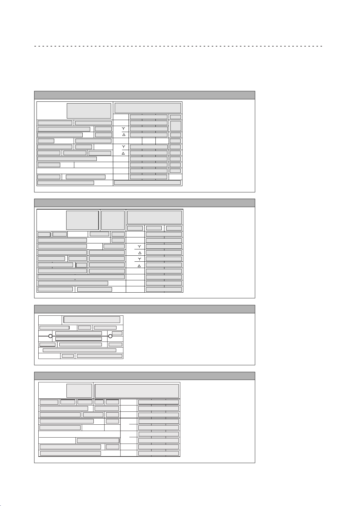
3.2.1 Nameplate
Geared motor with a directly mounted motor (layout A)
L
2
3
4
5.1
5.3
6
8.1
9
10.2
11
8.2
7.1
1
21
18
17
5.2
5.4
7.2
8.3
10.3
15
Hz
kW
V
A
r/min
h %
cos j
C86
20.1
16.1
16.2
16.4
16.4
16.5
16.5
16.3
16.7
16.6
22
Geared motor with a directly mounted motor (layout B, with QR code)
L
2
14.1
3
4
5.1
5.3
6
8.1
8.2
20.1
11
10.2
9
1
5.4
7.1
8.3
10.3
21
5.2
30
7.2
33.1
43
14.3
18
17
33.2
15
r/min
h %
cos j
C86
13
Hz
16.1
16.2
kW
16.4
16.4
16.5
16.5
16.3
16.7
16.6
22
23
V
A
26
15
19
23
13
14.1
14.2
14.3
27
14.2
Gearbox with motor adapter
L
3
5.1
11
1
6
10.2
18
5.4
5.3
7.2
10.3
30
20.1
17
27
4
5.2
7.1
Three−phase AC motor for motor adapter
L
2
4
21
8.1
9
10.2
11
8.2
14.2
10.3
1
14.1
23
15
26
22
13
8.3
14.3
27
20.1
18
Hz
kW
r/min
V
A
cos j
h %
16.1
16.2
16.3
*
-
*
-
16.4
16.4
16.5
16.5
16.6
16.7
16
Lenze ¯ MA 12.0014 ¯ 5.1
Page 17

Pos. Contents
1 Manufacturer / production location
2 Type of motor / standard
3 Gearbox type
4 Motor type
5 Technical data
5 5.1 Ratio
5 5.2 Rated torque
5 5.3 Rated speed
5 5.4 Rated frequency
5 5.5 Rated voltage
5 5.6 Rated current
5 5.7 Maximum current
5 5.8 Rated power [kW]
5 5.9 Rated power [HP]
5 5.10 Continuous standstill torque
6 Position of system modules / mounting position
7 Lubricant details
7 7.1 Lubricant amount
7 7.2 Lubricant type
8 Brake data
8 8.1 Type
8 8.2 AC/DC brake voltage
8 8.3 Braking torque, electrical power input
9 Feedback / pulse encoder or resolver data
10 Production data
10 10.2 Material number
10 10.3 Serial number
11 Bar code
13 Information with regard to the operating mode
14 Additional motor specifications
14 14.1 Temperature class
14 14.2 Enclosure
14 14.3 Motor protection
15 Applicable conformities, approvals and certificates
16 Rated data for various frequencies
16 16.1 Hz = frequency
16 16.2 kW = motor power
16 16.3 rpm = motor speed
16 16.4 V = motor voltage
16 16.5 A = motor current
16 16.6 cos j = motor power factor
16 16.7 h = motor efficiency: at a rated power of 100%
17 Application factor / load capacity
18 Year of manufacture / week of manufacture
19 UL file number
20 Customer data
20 20.1 Additional customer data
21 UL category (e.g. inverter duty motor)
22 C86 = motor code for inverter parameterisation (code 0086)
23 Efficiency class
26 CC number Department of Energy (optional)
27 Permissible ambient temperature (e.g. Ta £ 40°C)
30 Weight
33 Encoder data
33.1 Encoder type
33.2 Encoder voltage
43 Internal key: QR code
Product description
Identification
Nameplate
3
Lenze ¯ MA 12.0014 ¯ 5.1
17
Page 18
3
Product description
Gearbox code
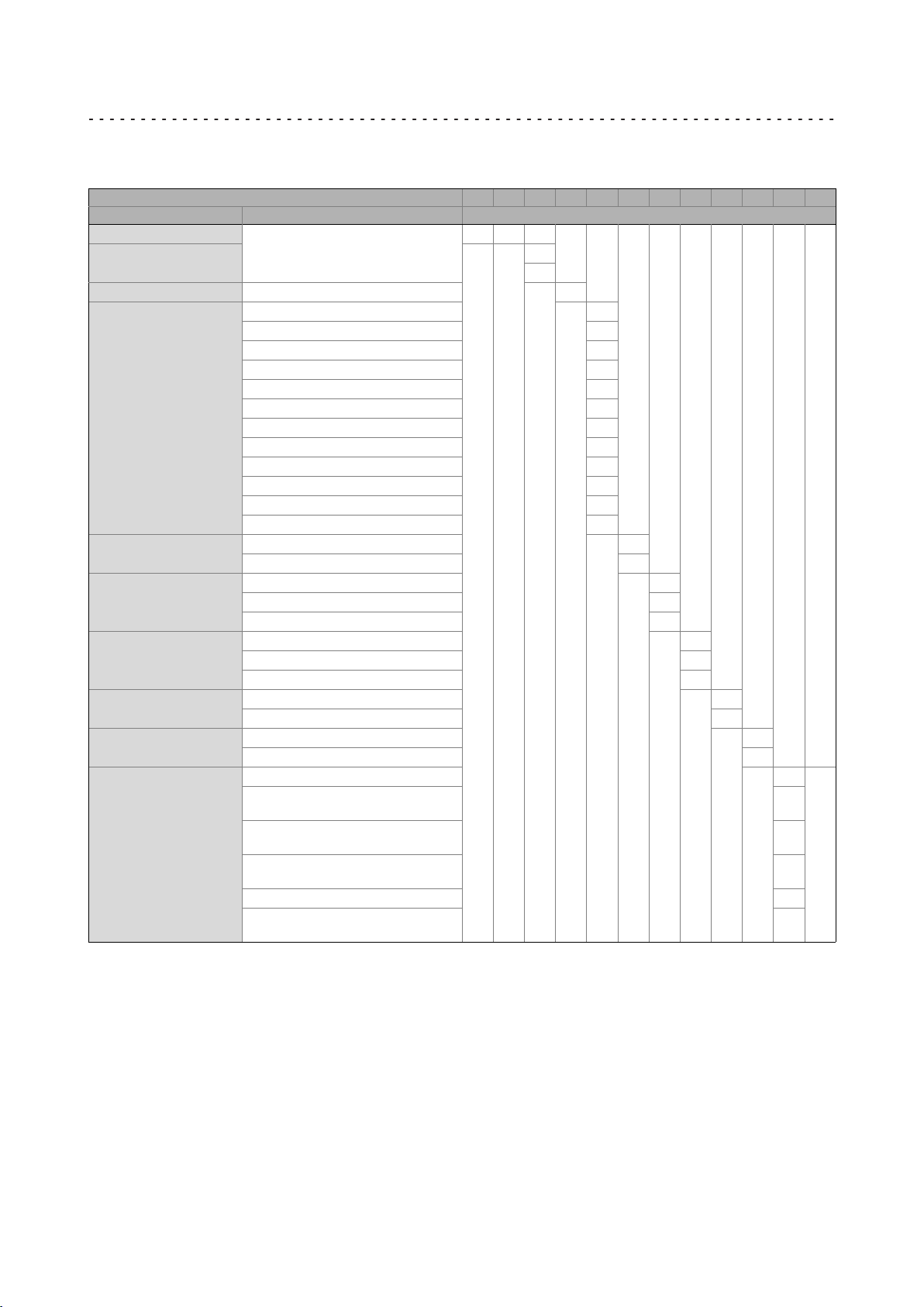
3.2.2 Gearbox code
Example G 50 A B 045 M H B R 2 N 2E
Meaning Variant Gearbox code
Product family G 50
Generation A
B
Gearbox type Bevel gearbox B
Output torque 45 Nm 045
110 Nm 111
240 Nm 124
450 Nm 145
600 Nm 160
820 Nm 182
1500 Nm 215
2700 Nm 227
4300 Nm 243
8000 Nm 280
13000 Nm 313
20000 Nm 320
Type of construction Geared motor M
Gearbox N
Shaft type Solid shaft with featherkey V
Hollow shaft with keyway H
Hollow shaft with shrink disk S
Housing type Foot mounting + centering A
Flange mounting Without flange R
Number of stages 2−stage 2
Drive size Without adapter (integrated motor) C
Foot mounting B
Centering C
Flange with through holes K
3−stage 3
NEMA adapter with a jaw coupling
with a keyway
NEMA adapter with a plug−in hollow
shaft with a keyway
IEC adapter with a plug−in hollow shaft
with a keyway
IEC adapter with a jaw coupling N
IEC adapter with a jaw coupling with a
keyway
A
00
...
B
82
H
1A
...
2K
T
18
Lenze ¯ MA 12.0014 ¯ 5.1
Page 19
4 Mechanical installation
1.
2.
4.1 Important notes
¯ Use load carrying equipment for transport!
¯ Before the transport
– check that all components are safely mounted,
– fasten all transport aids (eye bolts or support plates).
} Danger!
Danger due to toppling or falling loads!
¯ The payload of the hoists and load handling devices must at least
correspond to the weight of the load.
¯ Secure the load handling device so that it won’t slip from its position.
¯ The load must be secured in such a way that it cannot topple or fall
down.
¯ Do not stay under a pending load!
Mechanical installation
Important notes
4
4.2 Transport
} Danger!
The motors attached to the gearbox are partially equipped with eyebolts.
They are exclusively determined for mounting/dismounting the motor to
the gearbox and must not be used for the complete geared motor!
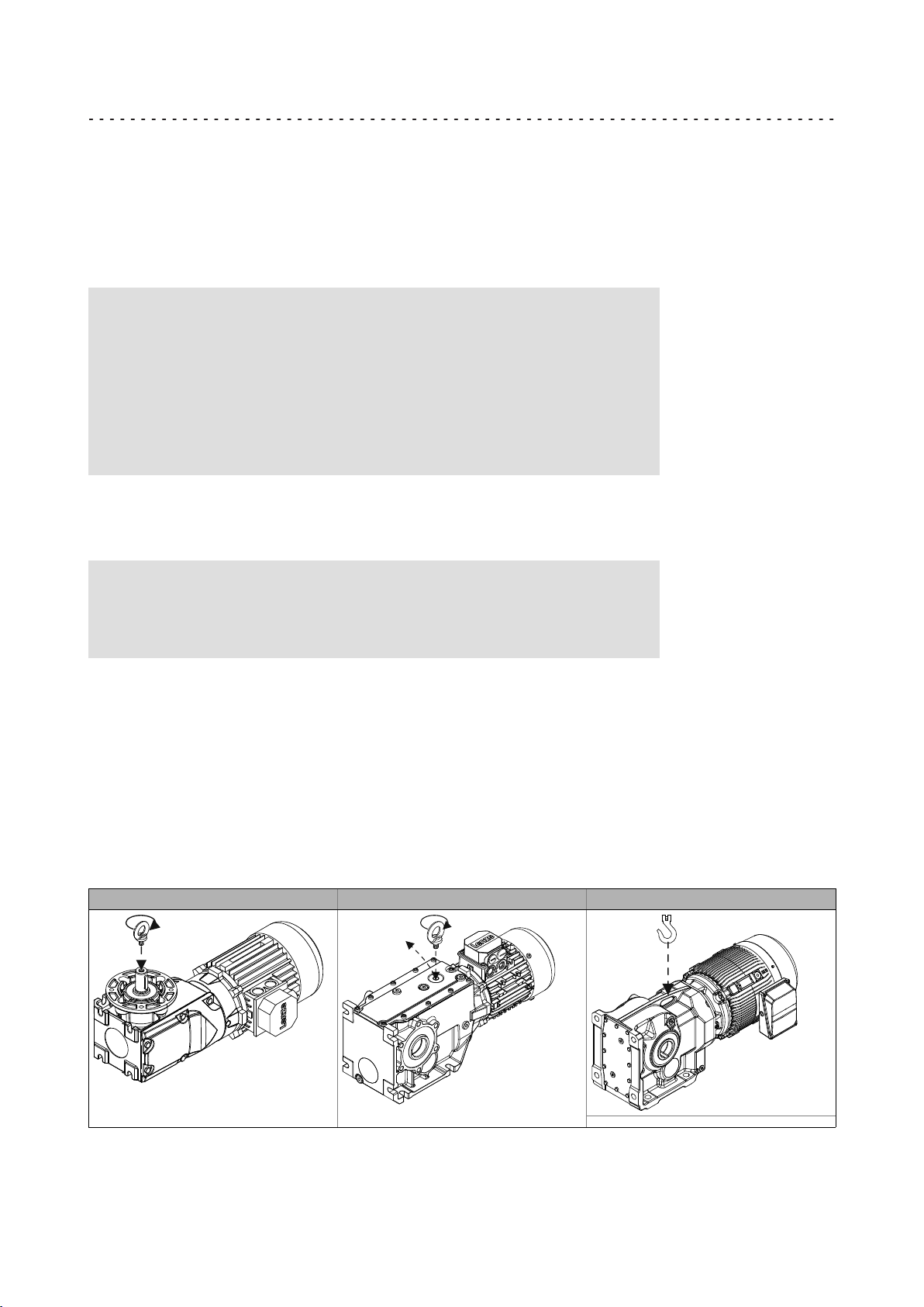
The position of the transport holes can be gathered from the illustrations shown in the
following. As a standard, the G50BB145 ... G50BB243 size gearbox is provided with
transport holes for eye bolts complying with DIN 580 in the gearbox cover. The eye bolt
is not included in the scope of supply!
For the smaller drives with solid shafts, the output shaft thread can be used or the drive
is transported using a securing rope. The rope should be wrapped around the round area
between the motor−gearbox interface.
The gearboxes of sizes G50BB280 ... G50BB320 can be lifted at the ear that is cast on to
the housing.
G50A0B45 ... G50BB124 G50BB145 ... G50BB243 G50BB280 ... G50BB320
Fig. 1 Positioning of the eye bolt for transporting the complete drive system
Lenze ¯ MA 12.0014 ¯ 5.1
19
Page 20
4
Mechanical installation
Transport
) Note!
As standard, threads are delivered with plug screws. The plug can be
easily removed, e.g. by using a screwdriver blade. For the thread size and
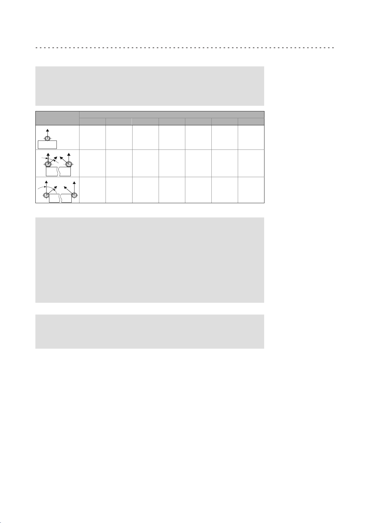
load carrying capacity of the eye bolt, please see Tab. 1.
Eye bolt position
£45°
£45°
Tab. 1 Load carrying capacity of each eye bolt in kg
M6 M8 M10 M12 M16 M20 M24
80 140 230 340 700 1200 1800
−−−−− 100 170 240 500 860 1290
−−−−− 70 115 170 350 600 900
} Danger!
Completely screw in transport aids (such as eye bolts or bearing plates),
they must be flat and applied over their entire surface!
If possible, the transport aids (such as eye bolts or bearing plates) must
be stressed vertically in the direction of the screw axis! Angular tension or
tension to the sides reduces the payload! Observe the information
provided in DIN 580!
Use additional appropriate lifting aids, if required, to achieve a direction
of loading which is as vertical as possible (highest payload). Secure lifting
aids against shifting!
Thread
( Stop!
Observe load carrying capacity!
Standing beneath floating loads is prohibited!
20
Lenze ¯ MA 12.0014 ¯ 5.1
Page 21

Mechanical installation
4.3 Preparation
¯ Protect shaft sealing rings against contact with solvents!
¯ Thoroughly remove anticorrosion agents from the output shaft and from flange
faces.
¯ Repair paintwork damage.
¯ In some cases, due to lack of space, stud bolts with nuts must be used instead of
head screws. In these cases, contact Lenze, if necessary.
Tighten all screw connections with the torques given and lock them with standard
screw locking adhesive!
Thread
M3 M4 M5 M6 M8 M10 M12 M16 M20 M24 M27 M30 M36
Strength Tightening torque [Nm]
4.8 0.7 1.4 2.8 4.8 12 23 − − − − − − −
8.8 1.3 3.0 5.9 10.1 24.6 48 84 206 415 714 1050 1428 2482
10.9 1.9 4.6 8.6 14.9 36.1 71 123 302 592 1017 1496 2033 3535
Tab. 2 Tightening torques for friction factor m = 0.12; tolerance of the tightening torque ±10 %
Please note: increase the tightening torque by 10% for screwed connections with flat
gaskets.
4
Preparation
Correcting the lubricant amount
If the oil quantity in the gearbox has been increased for longtime storage ((¶ 10)), the
oil must be drained completely and then must be refilled for the mounting position
provided. The following steps must be complied with:
1. Place receptacle under oil drain plug.
2. Remove breathing / oil filler plug.
3. Completely drain lubricant.
4. Screw in oil drain plug.
5. Fill in amount of oil for the mounting position provided (according to nameplate).
6. Screw in ventilation / oil filler plug.
Condensation drain hole
) Note!
Lenze delivers motors with condensation drain holes with sealed
condensation drain holes. The holes are sealed with a plastic plug or a
locking screw. This does not affect the type of protection and the motor is
protected against the ingress of foreign substances during transport and
operation. Further information, (¶ 64).
Lenze ¯ MA 12.0014 ¯ 5.1
21
Page 22

4
4.3.1 General information about the assembly of drive systems
Mechanical installation
Preparation
General information about the assembly of drive systems
( Stop!
The lubricant fill quantity of the gearboxes is matched to the mounting
position. The mounting position indicated on the nameplate must be
observed to avoid damage to the gearbox.
¯ Take safety measures prior to any operation:
– Disconnect the machine from the mains, ensure standstill of the drive system
and avoid any machine movement.
– Check faultless state of the drive system. Never install and commission
damaged drive systems.
– Check drive function - machine function assignment. Check direction of rotation
(¶ 46).
¯ The mounting areas / the foundation:
– must be plane, torsionally rigid, and free from vibrations,
– must be suited to absorb the forces and torques generated during operation,
– should have vibration−absorbing properties.
¯ Align drive system on mounting surfaces exactly with the machine shaft to be
driven.
– Be sure to carry out mounting in a manner free from distortion, in order to avoid
additional loads.
– Even out slight inaccuracies by the use of suitable flexible couplings.
¯ Support reaction torque by suitable measures.
¯ Be absolutely sure to secure fastening fixtures of accessories and built−on
accessories against unintended loosening. We recommend:
– the use of screws with a minimum property class of 8.8.
– with steel or cast iron output flanges, in particular for applications with an
alternating load, the use of screws with a strength of 10.9 with correspondingly
high tightening torques.
– Secure screwed connections with medium strength using screw locking
adhesive.
22
Lenze ¯ MA 12.0014 ¯ 5.1
Page 23

Mechanical installation
Gearboxes with breathers
4.3.2 Gearboxes with breathers
( Stop!
Do not place gearbox onto breather valve!
The G50BB045 ... G50BB124 gearboxes do not require any ventilation measures.
Gearboxes that are delivered with a ventilation unit are provided with a label.
Remove the transport locking device on the vent valve before initial commissioning.
4
Preparation
) Note!
Loosely enclosed vent valves must be mounted in accordance with the
mounting position, (¶ 50).
GT−GNG−13285760.iso/dms
Lenze ¯ MA 12.0014 ¯ 5.1
23
Page 24

4
4.3.3 Gearbox with compensation container (preferably for mounting pos. "C")
Temperature fluctuations generate changes in the lubricant volume. A compensation
reservoir serves to compensate for the change in volume in each case.
The compensation reservoir is supplied as a mounting set. Before commissioning, the
oil vent plug must be replaced with the reservoir.
Mounting and dismounting: , mounting instructions for the compensation reservoir
Mechanical installation
Preparation
Gearbox with compensation container
( Stop!
For transporting the geared motor, the compensation reservoir must be
removed and the gearbox must be locked by means of a locking screw.
( Stop!
Leaky pipe to the oil compensation reservoir
The pipe of the oil compensation reservoir is subjected to a natural
ageing process.
Possible consequences:
¯ Environmental impact
Protective measures:
¯ Make sure that the pipe does not show any signs of cracks or leakage.
¯ Do not commission a leaky pipe.
¯ If the pipe shows any signs of damage, replace it.
) Note!
With unfavourable combinations of a small ratio and a high input speed,
the use of a compensation reservoir may also be advisable in other
mounting positions.
24
Lenze ¯ MA 12.0014 ¯ 5.1
Page 25

Mechanical installation
Mounting the gearboxes
4.3.4 Mounting the gearboxes
( Stop!
Shocks and impacts on the shaft damage the roller bearings.
¯ Draw the transmission elements onto the output shaft only by using the
centering thread.
¯ Align the gearbox shaft and transmission elements in an accurate fashion in order
to prevent tensioning.
¯ Mount belt pulleys, sprockets, or gear wheels as closely as possible to the gearbox
in order to keep the bending load of the shaft and the bearing forces at a
minimum level.
Gearbox with output flange
¯ Especially with regard to applications with an alternating load, Lenze
recommends...:
– the use of anaerobic adhesive between the gearbox flange and mounting area
in order to increase the friction fit;
– with steel or cast iron output flanges, the use of screws with a strength of 10.9
with correspondingly high tightening torques.
4
Preparation
Lenze ¯ MA 12.0014 ¯ 5.1
25
Page 26

4
Mechanical installation
Preparation
Maximum permissible load at the motor adapter
4.3.5 Maximum permissible load at the motor adapter
( Stop!
¯ The loads generated by the motor mounted must be checked!
¯ The forces F
not be exceeded!
mentioned (see following tables) at the adapter must
M
For the effective force F
, static forces (e.g. weight) and dynamic forces (e.g.
M
acceleration forces, for example caused by vibrations or start−up processes) have to be
taken into consideration.
Furthermore the loading case of the force FM has to be taken into consideration:
Loading case k
Static 1
Dynamic−pulsating 0.8
Dynamic−alternating 0.6
loading case
The position of the motor‘s centre of gravity, including all motor options, must be
calculated. If the distance of the centre of gravity L
is greater, the permissible force
Tab
must be reduced as follows.
L
F
Mperm
+ k
loading_case
@ F
MTab
@
Tab
L
v k
loading_case
@ F
MTab
If forces act from several directions, e.g. in the case of a moving horizontal travelling
drive, the acting forces have to be added vectorially (e.g. vertical force due to weight plus
horizontal acceleration force).
F
corresponds to the maximum value of the forces added vectorially!
Mperm
L
F
M
If the permissible force F
is exceeded, the motor has to be supported in a suitable,
Mperm
distortion−free fashion!
Drive size
IEC NEMA
xA/2B
1B − 80 450 600 800 800
xC 5C 115 450 600 800 800
xD 5D 115 450 660 1000 1500
N
xE 5E 145 −−−−− 660 1000 1500
xF − 145 −−−−− −−−−− −−−−− 1500
xG 5G 190 −−−−− −−−−− −−−−− −−−−−
xH xH 250 −−−−− −−−−− −−−−− −−−−−
A
Distance L
of the motor
A 80 350 350 350 350
Tab
B110
G50BB111
[mm] Maximum permissible force F
Gearbox type
B240
G50BB124
B450
G50BB145
26
M Tab
B600
G50BB160
[N]
Lenze ¯ MA 12.0014 ¯ 5.1
Page 27

Mechanical installation
Preparation
Maximum permissible load at the motor adapter
4
Drive size
IEC NEMA
xA/2B
1B − 80 800 800 −−−−− −−−−−
xC 5C 115 800 800 −−−−− −−−−−
xD 5D 115 1500 1500 1500 1500
N
xE 5E 145 1500 1500 1500 1500
xF − 145 1500 1500 1500 1500
xG 5G 190 1700 1700 1700 1700
xH xH 250 −−−−− 2600 3500 3500
Drive size
IEC NEMA
51
55 18 145 2220 2210 −
55 − 145 2500 2490 2450
61 21 190 4490 4480 4420
65 25 250 5230 5230 5230
H
T
66 28 250 4500 4500 4500
70 − 300 3720 3720 3720
76 32 300 6980 7100 7100
81 36 400 6200 6880 6880
82 − 400 − 11400 11400
A
A
B
Distance L
of the motor
− 80 350 −−−−− −−−−− −−−−−
Distance L
of the motor
14 115 1540 − −
Tab
B820
G50BB182
[mm] Maximum permissible force F
Tab
B8000
G50BB280
[mm] Maximum permissible force F
Gearbox type
B1500
G50BB215
Gearbox type
B13000
G50BB313
B2700
G50BB227
B20000
G50BB320
[N]
M Tab
M Tab
B4300
G50BB243
[N]
Lenze ¯ MA 12.0014 ¯ 5.1
27
Page 28

4
Mechanical installation
Preparation
Mounting of motors to gearboxes with an adapter
4.3.6 Mounting of motors to gearboxes with an adapter and a flexible coupling
When mounting a motor to an adapter, be sure to observe a fully circumferential
contact of the flange faces, thus ensuring that there is no aperture to the interior of the
adapter.
With higher degrees of protection or when there is a risk of dirt or humidity entering,
additionally seal the contact surfaces with a suitable sealant.
m
1
2
d
ø
l
m
Spider / gear rim 1 Locking screw
0
Coupling hub 2 Keyway
1
B14/ FT
B5/FF
g500−H_X−002.iso
28
Lenze ¯ MA 12.0014 ¯ 5.1
Page 29

Adapter for IEC motors
Mechanical installation
Preparation
Mounting of motors to gearboxes with an adapter
4
Drive size
IEC
N1A 11 23 23 M4 1.5 M3 1.34
N1B 14 40 25 M5 2.0 M6 10.5 B5 x 5 x 16 M4 3.0
N2B 11 23 23 M4 1.5 M3 1.34
N1C 19 40 25
N2C 14 40 25
N3C 14 40 25
N4C 14 40 25
N6C 11 40 25 −−− −−−
N7C 19 40 25
N1D 24 60 30
N2D 19 60 30 B6 x 6 x 18
N1E 28 60 30
N2E 24 60 30
N3E 19 60 30 B6 x 6 x 18
N4E 24 50 50
N1F 28 60 30
N2F 24 60 30
N3F 24 50 50
N1G 38 80 80
N3G 38 80 80
N1H 42 110 110
N2H 48 110 110
N3H 38 80 80
T51 24 50 50
T55 28 60 60
T55 28 60 60
T61 38 80 60
T65 42 110 111
T66 48 110 109
T70 55 110 110
T76 60 140 140
2)
T81
T82 75 140 136
Motor shaft Assembly
dimension
d
max. l
[mm]
1)
2)
[mm]
65 140 140
Featherkey with a standard hub and clamping hub
T81 only valid for motor frame size 250, 4−pole
m
[mm]
Standard hub
Locking screw
Thread Tightening
torque
[Nm]
M5 2.0
M5 2.0
M8 10
M5 2.0
M8 10
M10 17
Clamping hub Featherk
Thread Tightening
torque
6885/1
[Nm]
B6 x 6 x 16
M6 10.5
M6 10.5
M8 25N2G 28 60 60
B5 x 5 x 16
B6 x 6 x 16 M4 3.0
B8 x 7 x 18
B8 x 7 x 18
B8 x 7 x 18
ey
DIN
[mm]
Clamping ring hub
1)
Thread Tightening
*
*
*
*
M3 1.34
M3 1.34
M4 3.0
−−− −−−
M5 6
*
M10 69 M8 35
−−− −−−
*
−−− −−−
torque
[Nm]
Adapter for NEMA motors
Drive size
NEMA
A5B
A5C
A5D 22.225 54 54.0
A5E 28.575 67 66.7
A5G 34.925
A5H 41.275 102.0
A6H 47.625 112 111.1
A14 22.225 57.15 53
A18 28.575 69.85 66.5
A21 34.925 85.725 79
A25 41.275 101.6 95
A28 47.625 117.475 111
A32 53.975 133.35 127
A36 60.325 149.225 143
Motor shaft Assembly
dimension
d
max. l
[mm]
15.875 54 40.0
[mm]
102
m
[mm]
101.5
2)
2)
2)
2)
2)
2)
2)
2)
2)
2)
2)
Tab. 3 Attachment of motors to gearboxes with adapter
* Use original featherkey of the motor
1) Featherkey for standard hub and clamping hub
2) Measured from the seating face of the motor flange
Lenze ¯ MA 12.0014 ¯ 5.1
Standard hub
Locking screw
Thread Tightening
M5 2.0 M6 10.5
M8 10
M5 2.0
M8 10
M10 17
torque
[Nm]
Clamping hub Featherk
ey
Thread Tightening
torque
[Nm]
M8 25
M10 69 M8 35
−−− −−−
DIN
6885/1
[mm]
B4.76 x 4.76
x 20
Clamping ring hub
1)
Thread Tightening
M4 3
M5 6
*
*
−−− −−−
torque
[Nm]
29
Page 30

4
4.3.7 Coupling hubs
General
Mechanical installation
Preparation
Coupling hubs
) Note!
Standard hubs, clamping hubs and clamping ring hubs are
maintenance−free.
We recommend carrying out a visual inspection of the star−shaped
spider/ring gear and the system parts within the inspection intervals.
) Note!
Tighten all screws to the coupling hubs and the motor fastening of
gearboxes in ATEX design with an intermediate strength screw retention.
Mounting the standard hub / clamping hub
1. Fit motor keyway (2).
– With some sizes a shorter featherkey is supplied, which is to be mounted. The
sizes concerned by this are shown on (¶ 29)
2. With a clamping hub:
– slightly loosen the clamping screw
– Fit coupling hub on the motor shaft using a center hole thread (do not mount by
hammer strokes, in order to avoid damage to the roller bearings in the motor).
– Observe mounting dimension m of the coupling hub (¶ 28).
3. Secure coupling hub against axial movement using the fixing screw or clamping
screw (1).
4. Lay spider in the coupling claw on the gearbox side.
– The mounting process can be facilitated by lightly greasing or oiling the ring
gear sides or the hub sides. For this purpose, only use mineral oil−based
lubricants without additives, silicone−based lubricants, or vaseline.
5. Align claws of the motor−side coupling hub with its counterpart.
6. Slowly push on motor, and bolt on to the gearbox flange.
30
Lenze ¯ MA 12.0014 ¯ 5.1
Page 31

Mounting the clamping ring hub
2
Fig. 2 Coupling
1 Clamping ring hub
2 Clamping ring
3 Clamping screws (DIN912)
Mechanical installation
Preparation
Coupling hubs
1
3
4
) Note!
The motor shaft must be designed with fit k6.
1. Slightly oil contact surfaces of the motor shaft using low−viscosity lubricating oil
such as Castrol 4 in 1" or Klüber Quietsch Ex".
( Stop!
Do not use oils and greases with molybdenum disulphide or extreme
pressure additives such as lubricating grease pastes!
2. Slightly loosen clamping screws in the coupling hub.
– Fit coupling hub on the motor shaft using a center hole thread (do not mount by
hammer strokes, in order to avoid damage to the roller bearings in the motor).
– Observe mounting dimension m of the coupling hub (see Tab. 3).
3. Align hub and slightly tighten clamping screws until they are fitting closely.
4. Tighten the clamping screws evenly crosswise in several steps until the indicated
tightening torque is reached (see Tab. 3).
5. Lay spider in the coupling claw on the gearbox side.
– The mounting process can be facilitated by lightly greasing or oiling the ring
gear sides or the hub sides. For this purpose, only use mineral oil−based
lubricants without additives, silicone−based lubricants, or vaseline.
6. Align claws of the motor−side coupling hub with its counterpart.
7. Slowly push on motor, and bolt on to the gearbox flange.
Lenze ¯ MA 12.0014 ¯ 5.1
31
Page 32

4
Dismounting the clamping ring hub
1. Loosen the clamping screws evenly one after the other.
Mechanical installation
Preparation
Coupling hubs
( Stop!
Each screw must only be loosened by half a revolution per pass! Unscrew
all clamping screws by 3 − 4 threads.
2. Remove the screws next to the forcing threads and screw them into the other
threads until they have contact.
3. Tighten the screws in the forcing threads crosswise and step−by−step so that the
clamping ring is loosened.
4. Clean and grease all contact surfaces including threads and head of the clamping
screws before reassembly.
32
Lenze ¯ MA 12.0014 ¯ 5.1
Page 33

Mechanical installation
Preparation
Mounting of motors to gearboxes with a short adapter with a plug−in hollow shaft with a keyway
4.3.8 Mounting of motors to gearboxes with a short adapter with a plug−in
hollow shaft with a keyway (drive−end version B or H)
Ød
l
0
4
1
ü
û
g500−X−010
Fig. 3 Motors on gearboxes with a short adapter with a plug−in hollow shaft with a keyway
1 Plastic ring
2 Hollow shaft
A Correct
B Incorrect
) Note!
Ensure that the plastic ring is not twisted and that it is in the correct
position.
The plastic ring prevents fretting corrosion. It does not have to be
greased.
1. Check whether the dimensions of the motor shaft and the featherkey match the
hollow shaft bore and keyway.
2. Check whether the drill depth in the hollow drive shaft for the motor shaft is
sufficient. For this purpose, compare the drill depth from the flange face with the
distance of motor shaft front side to the motor flange.
3. Check whether the opening of the plastic ring to the keyway in the hollow shaft is
aligned correctly and correct it, if necessary.
4. Align the featherkey in the motor shaft to the keyway in the hollow shaft.
5. Position the motor shaft centrically to the hollow drive shaft and then insert it
into the hollow drive shaft carefully, only exerting little force, in order to avoid
damaging the ball bearings in the bell housing and the motor. By no means join
the parts by hammer strokes!
6. Screw the motor and gearbox flange together, securing the fixing screws using
medium−strength screw locking adhesive.
Lenze ¯ MA 12.0014 ¯ 5.1
33
Page 34

4
4.3.9 Attachment of gearboxes with hollow shafts and keyway
1. If necessary, remove anti−corrosion coating in the hollow shaft and on the
2. Check the seat and edges of the hollow shaft and the machine shaft for damage.
3. Apply a fitting grease (Fig. 4) to the shaft and into the hollow shaft bore.
4. Mount gearbox with hollow shaft on the machine shaft to be driven, ensuring
Mechanical installation
Preparation
Attachment of gearboxes with hollow shafts and keyway
machine shaft.
Rework, if necessary. Ensure good concentricity of the machine shaft in order to
avoid unnecessary additional forces caused by tensioning.
exact alignment. In the mounting process, lead forces only across the hollow shaft
and not across the housing.
Paste gegen
Passungsrost
2.
3.
1.
4.
Fig. 4 Application of fitting grease against fretting corrosion
( Stop!
Take up forces only via the hollow shaft, and not via gearbox housing.
5. Secure the gearbox axially:
– The hollow shaft has snap ring grooves for axial securing. Parts used to fix the
shaft are not included in the scope of supply.
g500−B−MoPa−001
K12.0611
34
Lenze ¯ MA 12.0014 ¯ 5.1
Page 35

Mechanical installation
Attachment of gearboxes with hollow shafts and keyway
Auxiliary tool (recommended dimensions)
H7
Æ d
18
20
25
30
35 M12 7
40
45
50
55
60
65
70
80
90
100
120
Tab. 4 Dimensions in [mm]
6. Cover rotating screw heads, interfering edges, slots or similar items safe against
contact.
d
2
M6 4
M10
M16
M20
M24
c
10
11
13
13
14
16
20
24
24
7
5
6
8
9
4
Preparation
Lenze ¯ MA 12.0014 ¯ 5.1
35
Page 36

4
Mechanical installation
Preparation
Attachment of gearboxes with hollow shafts and keyway
Dismounting
( Stop!
¯ Before dismantling the machine shaft, mount an adequately
dimensioned load handling device at the gearbox.
¯ Ensure pretensioning of the drive mechanism, preventing the gearbox
from falling into the drive mechanism when it is loosened from the
plug−in shaft.
¯ When removing the hollow shaft via the housing, impermissibly great
forces may be generated.
¯ Tensioning of the hollow shaft causes a bearing failure and damage of
the gearbox housing.
1. Undo axial gearbox locking in the hollow shaft.
2. Remove/extract the gearbox from the motor shaft using an appropriate auxiliary
tool (Fig. 5).
Fig. 5 Disassembly of gearboxes with hollow shaft, with auxiliary tool
Auxiliary tool (recommended dimensions)
H7
Æ d
30 7.8 8 3 2 29.8 M10 18 33 5.5
35 *
35
40 11.8 12 4 −−− 39.8 M16 −−− 43 6
45 13.8 12 4 −−− 44.8 M16 −−− 48.5 7
50 13.8 12 5 −−− 49.8 M16 −−− 53.5 7
55 15.8 16 5 −−− 54.8 M20 −−− 59 7.5
60 17.8 16 5 −−− 59.8 M20 −−− 64.1 8
70 19.8 16 5 −−− 69.8 M20 −−− 74.1 8
80 21.8 20 5 −−− 79.8 M20 −−− 85.1 9
90 24.8 10 10 −−− 89.8 M20 72 95 11
100 27.8 15 10 −−− 99.8 M24 80 106 12
120 31.8 15 10 −−− 119.8 M24 80 127 15
Tab. 5 Dimensions in mm
b ±0.1 c
9.8 7 3 5 34.8 M12 20 38 6
9.8 12 3 −−− 34.8 M12 −−− 38 6
* Auxiliary tool for gearbox size G50BB124
8
c
9
c
10
d1 ±0.1 d
2
d
3
t −0.1 t
1
36
Lenze ¯ MA 12.0014 ¯ 5.1
Page 37

) Note!
l
l
2
l
1
l
2
In the case of the bevel gearbox the hollow shafts are released to rotate
freely in the central part, i.e. the hole diameter is greater by 0.1 mm in
this area! Provide for a sufficient length of the machine shaft so that the
machine shaft is guided on both sides.
Mechanical installation
Preparation
Attachment of gearboxes with hollow shafts and keyway
4
Gearbox
Code Type
G50AB045 g500−B45 85 22 100
G50BB111 g500−B110 105 25 120
G50BB124 g500−B240 127 25 143
G50BB145 g500−B450 117 50 150
G50BB160 g500−B600 133 57 170
G50BB182 g500−B820 143 60 180
G50BB215 g500−B1500 163 70 210
G50BB227 g500−B2700 188 80 240
G50BB243 g500−B4300 234 100 300
G50BB280 g500−B8000 260 135 350
G50BB313 g500−B13000 310 150 410
G50BB320 g500−B20000 380 180 500
Tab. 6 Dimensions in mm
l1 min l
2
l max.
Lenze ¯ MA 12.0014 ¯ 5.1
37
Page 38

4
4.3.10 Mounting the shrink disc with a rotating cover
Mechanical installation
Preparation
Mounting the shrink disc with a rotating cover
( Stop!
¯ Do not disassemble new shrink disc.
¯ Never tighten clamping screws before the machine shaft has been
inserted, since otherwise the hollow shaft may undergo plastic
deformation.
¯ During operation, the shrink disc has to be covered so that it is safe
against contact by implementing suitable measures (e.g. cover).
¯ Degrease hollow shaft bore and machine shaft!
Depending on the design, the shrink discs may be equipped with a rotating cover
(pos. 1).
) Note!
This cover is fitted to the shrink disc on delivery.
1
1.
Fig. 6 Cover of the clamping screws
1 Protection cover
2 Clamping screws
1. Remove protective cap (1), if available.
2. Check machine shaft:
– Diameter in fit tolerance h6
– Material yield point Re > = 360 MPa
– E−module approx. 210000 MPa
– Surface roughness R
– Concentricity in order to prevent unnecessary additional forces caused by
tensioning.
£ 15 mm
z
2
1
8.
g500−B−001 des/dms
3. Thoroughly clean and degrease hollow shaft bore and machine shaft.
) Note!
Thoroughly degrease the bore over the entire hollow shaft length to
make sure that remainders of the anticorrosion agent will not be carried
off into the area of the shrink disc when pushing on the machine shaft.
4. Slightly loosen clamping screws (2) one after the other, do not unscrew!
5. Push drive onto machine shaft.
38
Lenze ¯ MA 12.0014 ¯ 5.1
Page 39

Mechanical installation
Mounting the shrink disc with a rotating cover
6. Slightly tighten clamping screws manually.
7. Tighten clamping screws (2) one after the other (see Fig. 7) in several passes, with
rising torque, evenly until the indicated screw−tightening torque (see Tab. 7 ) is
reached at all screws.
GT−GNG−003.iso/dms
Fig. 7 Explanation: "one after the other"
I Tip!
Several (in general more than 5 ) passes are necessary until the full
tightening torque is reached at all screws!
4
Preparation
The shrink disc is mounted correctly and fixed when the faces of the outer ring and the
inner ring are aligned (Fig. 8). Minimum misalignments are permissible.
GT−GNG−001.iso
Fig. 8 Hollow shaft with shrink disk
3 Outer ring
4 Inner ring
Hollow shaft bore [mm] 20 25 30 35 40
Clamping screw thread M6 M5 M6 M6 M8 M6 M8 M6 M8
Width across flats
1)
[mm]
SW
Torque [ Nm ] 12 6 14 14 30 14 30 14 34
Hollow shaft bore [mm] 50 65 75 80 95 105 125
Clamping screw thread M8 M10 M10 M10 M12 M14 M14
Width across flats
1)
[mm]
SW
Torque [ Nm ] 34 70 70 70 121 193 193
Tab. 7 Tightening torque for the clamping screws
1)
Width across flats of the shrink disc clamping screws
10 8 10 10 13 10 13 10 13
13 17 17 17 19 22 22
0
free of grease
Lenze ¯ MA 12.0014 ¯ 5.1
39
Page 40

4
Mechanical installation
Preparation
Mounting the shrink disc with a rotating cover
) Note!
If a different tightening torque is indicated on the shrink disc, this
tightening torque has priority over the value indicated in the table.
8. Push protective cap (1, Fig. 6) onto the shrink disc.
I Tip!
For finding out the cause of non−reached torques of the shrink disc
connection, please go through the troubleshooting list in chapter 8.
Dismounting
} Danger!
Loose drive components or drive components falling down may cause
injury to persons or damage to the machine. Secure the drive
components before disassembly.
1. Remove protective cap (1).
2. Loosen clamping screws (2) evenly one after the other each by ¼ revolution in
several passes. Do not unscrew clamping screws completely to prevent accidents!
3. Press off outer ring (see Fig. 8), if necessary. For this, loosen the outer ring using
the forcing threads and some clamping screws (number corresponding to the
forcing threads in the inner ring). For loosening the outer ring, screw in the screws
evenly to prevent canting. Press off the outer ring until loosened completely.
4. Remove the drive from the machine shaft.
( Stop!
Dismantle the shrink disc only for cleaning purposes. Afterwards, grease
bevel surfaces and screws using a solid lubricant with a friction factor of
m = 0.04.
¯ Suitable lubricants on molybdenum−disulphide lubricant (MoS2) basis are, e.g.:
– Molykote G Rapid (company Dow Corning)
– Molykote BR2 Plus (company Dow Corning)
– Molykombin UMFT1 (company Klüber Lubrication)
Usually, disassembly problems only occur if:
¯ the connection is spinning due to overload or a too low friction factor and fretting
corrosion has occurred,
¯ the shrink disc has been tightened too much leading to a plastic deformation of
components,
¯ the components are corroded.
40
Lenze ¯ MA 12.0014 ¯ 5.1
Page 41

X
X
4.3.11 Mounting the fixed cover
) Note!
This cover can be ordered optionally and will then be loosely enclosed
with the shipment, or it is already mounted to the gearbox.
Gearbox size: B45/G50BA045 ... B820/G50BB182
With these sizes, the protective cap is clipped on.
Mechanical installation
Preparation
Mounting the fixed cover
4
Gearbox size: B1500/G50BB215 ... B20000/G50BB320
With these sizes, the cover is screwed together with the housing.
Gearbox size: B1500/G50BB215 ... B4300/G50BB243
With these sizes, additional reducing bushs are screwed into the gearbox housing
thread.
x
x
1
3
2
1 Protection cover 3 Reducing bush
2 Cheese head screw
1. Screw reducing bushes (3) into the flange so that they are flush using a
screwdriver.
2. Fasten the protective cap (1) over the reducing bushes (3) on the flange using
cheese head screws (2).
Lenze ¯ MA 12.0014 ¯ 5.1
41
Page 42

4
4.3.12 Mounting the hoseproof hollow shaft cover
With the g500−B gearbox, the hoseproof hollow shaft cover is bolted down directly in
the housing.
Mechanical installation
Preparation
Mounting the hoseproof hollow shaft cover
A
A
1 Protection cover 4 Seal
2 Cheese head screw
1. Place seal (4) between the flange and the protection cover (1).
2. Fasten the protection cover (1) on the housing flange using cheese head screws
(2).
A-A
X
X
4
2
1
42
Lenze ¯ MA 12.0014 ¯ 5.1
Page 43

4.3.13 Torque plate assembly
( Stop!
Impermissible load caused by incorrect mounting:
¯ The socket of the torque plate must be mounted on both sides.
¯ When mounted, the socket must have axial clearance.
Mechanical installation
Preparation
Torque plate assembly
4
Fig. 9 Mounting of the torque plate at the base
The torque plate on the pitch circle can be mounted in various positions depending on
the pitch of the bore belt.
Fig. 10 Mounting of the pitch circle torque plate
) Note!
In the case of a knee lever design, transfer the force at right angles to the
torque plate, if possible (90°±20°).
Mounting
1. Clean the contact surfaces between the housing and torque plate.
2. Tighten the screws according to the torque specified, (¶ 21)
Lenze ¯ MA 12.0014 ¯ 5.1
43
Page 44

5
5 Electrical installation
Electrical installation
Motor connection
{ Danger!
Hazardous electrical voltage
The electrical installation has to be carried out by skilled personnel in
compliance with electrotechnical regulations and standards.
5.1 Motor connection
To correctly connect the motor, please observe:
¯ the notes in the terminal box of the motor
¯ the notes in the Operating Instructions of the motor
¯ the technical data on the motor nameplate.
5.2 Motor options
To correctly connect the motor options, e. g. brakes or feedback systems, please observe:
¯ the notes in the corresponding terminal box
¯ the notes in the corresponding operating instructions
¯ the technical data on the corresponding motor nameplate.
44
Lenze ¯ MA 12.0014 ¯ 5.1
Page 45

Commissioning and operation
6 Commissioning and operation
6.1 Important notes
( Stop!
The drive may only be commissioned by skilled personnel!
¯ Before commissioning remove transport locking devices and keep them for later
transports.
¯ Take safety measures prior to any operation:
– Disconnect the machine from the mains, ensure standstill of the drive system
and avoid any machine movement.
6.2 Before switching on
Check:
6
Important notes
¯ The oil level of the gearbox after previous long−term storage!
¯ That the drive does not show any visible signs of damage.
¯ Is the mechanical fixing o.k.?
¯ Has the electrical connection been implemented correctly?
¯ Are all rotating parts and surfaces that may become hot protected against
contact?
¯ For gearboxes with ventilation:
– Has the transport locking device been removed?
( Stop!
At drive speeds below 200 rpm the amount of lubricant may need to be
increased. Consultation with Lenze is required.
6.3 Initial commissioning
In order to ensure trouble−free operation, carry out checks during initial commissioning.
When Check
At initial start−up Rotating direction of the drive shaft ()
Continuously Monitor geared motor with regard to noticeable noise, vibrations,
and changes
After 3 hours under rated load Measure housing temperature (Tab. 9) at the hottest point. The value
measured at the same time serves as a reference value for later
measurements. If necessary, implement required measures if
temperatures are rising too high, ^ 46
Fastening elements, locking screws, and covers
Leakages: small quantities of escaping lubricant
After the first day Check oil level, ^ 59
Tab. 8 Measures at initial commissioning
Lenze ¯ MA 12.0014 ¯ 5.1
45
Page 46

6
Please check the following:
¯ Drive function - machine function assignment
¯ The direction of rotation of the drive shaft
All sizes except for G50BB124, 3−stage Only G50BB124, 3−stage
Fig. 11 Rotating direction of drive shaft
Commissioning and operation
During operation
6.4 During operation
¯ Warming
If operating conditions are unfavourable (e.g. high input speed, small ratio, vertical
mounting position, high ambient temperature, ...), the gearboxes may heat up more.
Temperature Measures
> 70 °C Apply covers and warning labels
> 80 °C Gearboxes with mineral oil (CLP) or for standard shaft sealing ring,
> 100 °C Gearboxes with synthetic oil (CLP HC) and FKM shaft sealing ring
Tab. 9 Housing temperature
During operation, check the drive periodically and take special care of:
¯ changes compared to normal operation, like
¯ Use synthetic oil,
¯ Provide for better cooling,
¯ It may be necessary to contact Lenze
¯ Provide for better cooling,
¯ It may be necessary to contact Lenze
– unusual noise, stronger vibrations or increased temperatures,
– leakages,
– loose fixing elements,
– the condition of the electrical cables.
¯ In the event of faults:
– shut down the drive,
– check the troubleshooting table.
If the fault cannot be remedied, please contact the Lenze customer service.
46
Lenze ¯ MA 12.0014 ¯ 5.1
Page 47

Maintenance
7 Maintenance
7.1 Important notes
) Note!
¯ Gearboxes below 250 Nm are lubricated for life.
¯ The mechanical power transmission system is maintenance−free.
¯ Before commissioning remove transport locking devices and keep them for later
transports.
¯ Take safety measures prior to any operation:
– Disconnect the machine from the mains, ensure standstill of the drive system
and avoid any machine movement.
7.2 Maintenance intervals
7
Important notes
( Stop!
For drive systems: Also observe the maintenance intervals for the other
drive components!
Dust deposits prevent heat to be emitted and cause a high housing temperature. The
gearboxes/geared motors must be purified of dirt and dust at regular intervals.
¯ In the case of gearboxes that are not lubricated for life, the lubricant must be
replaced at regular intervals.
– The type of lubricant is indicated on the nameplate. Replace the lubricant only
with the same type of lubricant.
– The lubricant change depends on the lubricant temperature, see Fig. 12.
1. Measure the lubricant temperature at the drain plug,
2. Add 10 °C,
3. Read the changing interval from the diagram.
Lenze ¯ MA 12.0014 ¯ 5.1
47
Page 48

7
Maintenance
Maintenance intervals
110
100
90
80
70
A
60
1000
B
Fig. 12 Lubricant diagram
Oil sump temperature [°C]
0
Oil life/changing intervals [operating
1
hours h]
10000
C
D
50000
Synthetic oil CLP HC/CLP PG
2
Mineral oil CLP
3
¯ Shaft seals and roller bearings:
– The service life depends on the operating conditions.
– Replace seals in case of leakage to avoid consequential damage.
Time interval Measures Description of the operations
On the first day, then every
month
Every 6 months
Annually Check vent valve Check whether air can pass through the
After 3h, then every 2 years Check fastening elements Check mounting of the gearbox (foot, flange
According to diagram; at
the latest as specified in
the lubricant table
Visual inspection Inspection regarding unusual operating noises,
Leakage test If leakages are found, eliminate their cause, see
Clean gearbox Remove dirt and dust deposits. To be inspected
Check rubber buffer Check rubber buffer of the torque plate and
Relubricate bell housings
of the roller bearing
Check pipe of the oil
expansion tank
Oil change Carry out oil change ^ 62 for type and amount
Replace roller bearing
grease filling
vibrations and impermissibly high
temperatures
"Troubleshooting" section
more frequently in the case of heavy dirt
accumulation
replace it in the event of visible wear or
damage
For bell housings with lubricating nipples:
relubricate roller bearing in bell housing using a
grease gun. Grease: Klüber Microlube GLY 92,
quantity approx. 5 grams
Replace pipe when it shows signs of leakage or
after 4 years
breather element. If it shows blockages, replace
it
and shrink disk mounting).
of lubricant see nameplate
When an oil change is carried out, the roller
bearing grease filling should also be replaced
^ 63
48
Lenze ¯ MA 12.0014 ¯ 5.1
Page 49

Maintenance
Maintenance operations
7.3 Maintenance operations
Gearboxes and geared motors are ready to use on delivery and filled by Lenze with the
lubricant type and lubricant quantity indicated on the nameplate. The first filling
corresponds to the mounting position and design indicated on the nameplate.
) Note!
Gearboxes of sizes G50AB045 ... G50BB124 are lubricated for life. Due to
the lower thermal load, no lubricant change and therefore no
arrangements for ventilation are required.
The G50BB124 gearbox can be optionally equipped with breather
elements.
7
Lenze ¯ MA 12.0014 ¯ 5.1
49
Page 50

7
7.3.1 Position of the lubricant monitoring elements
G50BB124
Mounting position A Mounting position B Mounting position C
Maintenance
Maintenance operations
Position of the lubricant monitoring elements
+
+
+
50
Filling Drain
Breathing Control
Lenze ¯ MA 12.0014 ¯ 5.1
Page 51

Maintenance
Maintenance operations
Position of the lubricant monitoring elements
Mounting position D Mounting position E Mounting position F
+
7
Filling Drain
Breathing Control
The shown oil bores are optional for gearbox size g500−B240!
Lenze ¯ MA 12.0014 ¯ 5.1
51
Page 52

7
G50BB145
Mounting position A Mounting position B Mounting position C
Maintenance
Maintenance operations
Position of the lubricant monitoring elements
+
+
+
52
Filling Drain
Breathing Control
Lenze ¯ MA 12.0014 ¯ 5.1
Page 53

Maintenance
Maintenance operations
Position of the lubricant monitoring elements
Mounting position D Mounting position E Mounting position F
7
+
+
+
Filling Drain
Breathing Control
Lenze ¯ MA 12.0014 ¯ 5.1
53
Page 54

7
Maintenance
Maintenance operations
Position of the lubricant monitoring elements
G50BB160 ... G50BB243
Mounting position A Mounting position B Mounting position C
+
+
+
+
G50BB160
G50BB182
G50BB215
+
G50BB227
G50BB243
54
Filler Drain
Breather element Check
Lenze ¯ MA 12.0014 ¯ 5.1
Page 55

Maintenance
Maintenance operations
Position of the lubricant monitoring elements
Mounting position D Mounting position E Mounting position F
+
+
+
G50BB227
G50BB243
7
+
G50BB215
G50BB160
G50BB182
G50BB227
G50BB243
G50BB215
Filler Drain
Breather element Check
G50BB215
+
G50BB160
G50BB185
G50BB215
Lenze ¯ MA 12.0014 ¯ 5.1
55
Page 56

7
G50BB280 ... G50BB320
Mounting position A Mounting position B Mounting position C
Maintenance
Maintenance operations
Position of the lubricant monitoring elements
+
*
+
+
*
*
56
*
*
Filling Drain
Breathing Control
Borehole on both sides
*
Lenze ¯ MA 12.0014 ¯ 5.1
Page 57

Maintenance
Maintenance operations
Position of the lubricant monitoring elements
Mounting position D Mounting position E Mounting position F
7
+
+
+
*
Filling Drain
Breathing Control
*
Lenze ¯ MA 12.0014 ¯ 5.1
Borehole on both sides
57
Page 58

7
Maintenance
Maintenance operations
Table of lubricants
7.3.2 Table of lubricants
Lenze recommends the use of the following lubricants.
If you carry out an oil change, use the same type of oil as specified on the nameplate. The
oil changing intervals are reference values for normal ambient conditions and a
maximum oil temperature of 70 °C. Difficult operating conditions (e.g. high
temperatures, aggressive ambient media) require shorter intervals.
Lubricant Ambient
CLP 220 0 °C ... + 40 °C Mineral oil with
CLP 460 0 °C ... + 40 °C Mineral oil with
CLP HC 220 −30 °C ... + 40 °C Synthetic oil
CLP HC 320 −20 °C ... + 50 °C Synthetic oil
CLP HC 220
USDA H1
CLP PG 460
USDA H1
temperature
−20 °C ... + 40 °C Synthetic oil
−20 °C ... + 40 °C Synthetic oil
Tab. 10 Overview of lubricant types
Lubricants with a USDA H1 approval are approved for the use in the food industry.
Specification
EP additives
EP additives
poly−alpha−olefin
poly−alpha−olefin
poly−alpha−olefin
H1 approval
with a polyglycol
H1 approval
with a
basis
with a
basis
with a
basis
basis
Changing intervals at 70°C Lubricant manufacturer
For the first
time after
16000 h 3 years Renolin
16000 h 3 years Renolin
25000 h 4 years Renolin Unisyn
25000 h 4 years Renolin Unisyn
16000 h 3 years Cassida Fluid
16000 h 3 years Cassida Fluid
Not later than
after
Fuchs Klüber Shell
CLP220 / CLP
Plus 220
CLP460 / CLP
Plus 460
CLP220 / XT 220
CLP320 / XT 320
GL 220
WG 460
Klüber oil
GEM 1−220 N
Klüberoil
GEM 1−460 N
Klübersynth
GEM 4−220 N
Klübersynth
GEM 4−320 N
Klüberoil
4 UH1−220 N
Klüberoil
UH1 6−460
Omala S2 G220
Omala S2 GXV
220
Omala S2 G460
Omala S2 GXV
460
Omala S4 GXV
220
Omala S4 GXV
320
−−−−−
−−−−−
) Note!
In case of ambient temperatures < −20°C or > +40°C, please contact
Lenze!
Observe increased starting torques at low temperatures!
58
Lenze ¯ MA 12.0014 ¯ 5.1
Page 59

Maintenance
Maintenance operations
Checking the oil level
7.3.3 Checking the oil level
) Note!
Check the oil level in cold condition!
Check the oil level by means of the displayed dipsticks. Manufacture them according to
the mounting position.
Form template: dipsticks for G50BB124
A, 3-stage
7
A, 2-stage
D
B
C
E
Lenze ¯ MA 12.0014 ¯ 5.1
F
59
Page 60

7
Form template: dipsticks for G50BB145
Maintenance
Maintenance operations
Checking the oil level
A
B
C
D
F
E
60
Lenze ¯ MA 12.0014 ¯ 5.1
Page 61

Geared motors G50BB160 ... G50BB320
1. Switch the drive to a deenergised state.
2. Remove oil control plug. (¶ 7.3.1)
3. Check oil level using a tool. If necessary, refill oil.
At the maximum, the oil level must be below the threaded hole by the dimension
x.
4. Check gasket and replace it, if necessary.
5. Tighten oil control plug.
Maintenance
Maintenance operations
Checking the oil level
7
G
X
ÖL
Fig. 13 Oil level in the gearbox housing
0
1 Auxiliary tool, e. g. angled wire (not included in the scope of supply)
2 Bleeder screw/oil filler plug
Oil−level bore d2 [mm] Filling height x [mm] Tightening torque [Nm]
M10 x 1 14 2 10
M12 x 1.5 17 3 20
M16 x 1.5 21 4 34
M20 x 1.5 25 5 50
G 1/8" 14 2.5 10
G 1/4" 18 3 10
G 3/8" 22 4 25
G 3/4" 32 7 50
90°
Oil check bore hole
d2
Lenze ¯ MA 12.0014 ¯ 5.1
61
Page 62

7
7.3.4 Changing the oil
Maintenance
Maintenance operations
Changing the oil
( Stop!
¯ The gearbox should be lukewarm in order that the oil flows well but
there is no risk of scalding.
¯ Secure the drive system and machinery against unintended movement
or mains power−up.
1. Place receptacle under oil drain plug.
2. Remove breathing / oil filler plug.
3. Completely drain lubricant by removing the oil drain plug.
4. Reinsert drain plug (if necessary, replace seal).
5. Fill in lubricant through filler hole (quantities see nameplate).
6. Screw in breathing / oil filler plug.
7. Dispose of waste oil according to the applicable regulations.
) Note!
Change from the CLP or CLP HC standard gearbox oil to the
food−compatible CLP xx xxx USDA H1 gearbox oil.
The oil drainage holes do not allow for complete draining of the gearbox
in all cases. Then a residual amount of oil remains in the gearbox. If a
change−over to a food−compatible gearbox oil is to be effected, the
gearbox must be rinsed thoroughly with the food−compatible gearbox oil.
62
Lenze ¯ MA 12.0014 ¯ 5.1
Page 63

Maintenance
Maintenance operations
Lubricate roller bearings
7.3.5 Lubricate roller bearings
The roller bearings on motors and gearboxes from Lenze are filled with the greases
listed below:
Ambient temperature Manufacturer Type
Gearbox roller bearing
Motor roller bearing
Special grease for gearbox roller bearings
Low−temperature oils,
observe critical starting
performance at low
temperatures
Biopetroleum (lubricant
for forestry, agriculture
and water supply and
distribution)
−30 °C ... +50 °C
−30 °C ... +80 °C
−40 °C ... +60 °C
−30 °C ... +70 °C
−40 °C ... +80 °C
−40 °C ... +80 °C Klüber Asonic GHY 72
−40 °C ... +50 °C Fuchs Plantogel 0120S
Fuchs
Klüber
Klüber
Lubcon
Klüber
Renolit H 443
Petamo 133 N
Microlube GLY 92
Thermoplex 2TML
Asonic GHY 72
7
) Note!
Clean roller bearings before applying new grease!
The following lubricant quantities are required:
¯ For fast−running bearings (drive−end gearbox): fill approx. one−third of the hollow
space between rolling bodies with grease.
¯ For slow−running bearings (within gearbox and driven side of gearbox): fill
approx. two−thirds of the hollow space between roller bearings with grease.
Lenze ¯ MA 12.0014 ¯ 5.1
63
Page 64

7
7.3.6 Drain condensation
Depending on the mounting position, the condensation drain holes are always at the
bottom of the motor!
¯ For condensate drainage
Maintenance
Maintenance operations
Drain condensation
– the motor must be deenergised;
– the plugs (screws) must be removed.
( Stop!
To restore the enclosure, re−insert the plugs (screws) after condensate
drainage. If the condensation drain holes are not sealed again, the IP
enclosure of the motor will be reduced. For horinzontal motor shafts to
IP23 and for vertical motor shafts to IP20.
Fig. 14 Motor with condensation drain holes
Condensation drain holes
0
64
Lenze ¯ MA 12.0014 ¯ 5.1
Page 65

7.4 Repair
¯ We recommend having all repairs carried out by the Lenze Service department.
Maintenance
Repair
Drain condensation
7
Lenze ¯ MA 12.0014 ¯ 5.1
65
Page 66

Troubleshooting and fault elimination8
8 Troubleshooting and fault elimination
If any malfunctions should occur during operation of the drive system, please check the
possible causes using the following table. If the fault cannot be eliminated by one of the
listed measures, please contact the Lenze Service.
Fault Possible cause Remedy
Drive is not running
Motor is running, but
gearbox is not running
Unusual running noises
Excessive temperature
Vibrations, noise Loose fixing elements Tighten fixing elements
Shrink disc connection is
spinning
Oil is leaking
Oil discharge at the gearbox
ventilation unit
Voltage supply interrupted Check connection
Faulty electrical connection Check that supply voltage
Excessive load Reduce load
Coupling components are missing or
defective
Gearbox is defective Inform Lenze Service
Clutch disengaged Engage the clutch
Overload Reduce load
Damage to the gearbox or motor Inform Lenze Service
Overload Reduce load
Inadequate heat dissipation Improve cooling air flow
Lack of lubricant Top up lubricant according to
¯ Correct screw tightening torque has not
been reached
– Insufficient number of passes, not all
screws are tightened correctly.
¯ Machine shaft and hollow shaft bore
not sufficiently degreased
¯ Wrong component part dimensions
– Fits, roughnesses
¯ Yield point of machine shaft material is
too low
– Re > 300 N/mm
¯ Friction factors are too low
– Coefficients of friction m ³ 0.15
required
¯ The shrink disc itself has been
degreased so that the screws and the
bevels are dry. Due to incorrect friction
factors, the shrink disc cannot be
tightened correctly.
Wrong oil level for the applied mounting
position
Initial insignificant leakage at the shaft
sealing ring
Overpressure due to lacking ventilation Install ventilation according
Overpressure due to polluted ventilation Clean ventilation
Worn−out shaft sealing rings Change shaft sealing rings
Cover / flange screws are loose Check that the fixing screws
Incorrect oil level for the mounting position
applied and/or incorrect position of
ventilation unit
2
required
matches nameplate data
Check drive−machine
assignment
Check mounting
Check drive−machine
assignment
Check drive−machine
assignment
Clean gearbox / motor
regulations
Specifications for assembly,
dimensions and material not
observed
Check mounting position
(see nameplate) and oil level
Optimum sealing conditions
only develop after the run−in
period
to the mounting position
are tightly fastened.
Continue to monitor the
gearbox
Mounting position (see
nameplate)
Check oil level^ 59
Check position of ventilation
unit ^ 50
Use oil compensation
reservoir
66
Lenze ¯ MA 12.0014 ¯ 5.1
Page 67

Notes !
Lenze ¯ MA 12.0014 ¯ 5.1
67
Page 68

© 09/2018 | MA 12.0014 | .Xqô | 5.1 | TD29
Lenze Drives GmbH
Postfach 10 13 52, 31763 Hameln
Breslauer Straße 3, 32699 Extertal
GERMANY
HR Lemgo B 6478
Ü
+49515482−0
Ø
+49515482−2800
Ù
lenze@lenze.com
Ú
www.lenze.com
Û
Lenze Service GmbH
Breslauer Straße 3, D−32699 Extertal
Germany
Ü
0080002446877 (24 h helpline)
Ø
+49515482−1112
Ù
service@lenze.com
10987654321
l
 Loading...