

Page 1

EDSPLCLIB03
13384448
Ä.GMQä
L-force Controls
Software Manual
Function library"CANopenSdoDrv"
for Lenze software »Drive PLC Developer Studio«
L
Page 2

Function library "CANopenSdoDrv"
Contents
Contents
1 About this documentation . . . . . . . . . . . . . . . . . . . . . . . . . . . . . . . . . . . . . . . . . . . . . . . . . . . . . . . . . 3
1.1 Conventions used
1.2 Definition of notes used
2 System requirements
3 Basics - Service Data Objects (SDOs)
3.1 Addressing through index and subindex
3.2 SDO services
4 Function blocks
4.1 IndexRead - read CAN index
4.2 IndexWrite - write CAN index
4.3 BlockRead - read CAN index per segmented data transfer
4.4 BlockWrite - write CAN index per segmented data transfer
5 Error numbers
6 Index
. . . . . . . . . . . . . . . . . . . . . . . . . . . . . . . . . . . . . . . . . . . . . . . . . . . . . . . . . . . . . . . . . . . . . . . . . . . . 23
Your opinion is important to us
. . . . . . . . . . . . . . . . . . . . . . . . . . . . . . . . . . . . . . . . . . . . . . . . . . . . . . . . . . . . . . . . . . . 9
. . . . . . . . . . . . . . . . . . . . . . . . . . . . . . . . . . . . . . . . . . . . . . . . . . . . . . . . . . . . . . . . . . . . 22
. . . . . . . . . . . . . . . . . . . . . . . . . . . . . . . . . . . . . . . . . . . . . . . . . . . . . . . . . . . . . . . 4
. . . . . . . . . . . . . . . . . . . . . . . . . . . . . . . . . . . . . . . . . . . . . . . . . . . . . . . . . . . . . . 6
. . . . . . . . . . . . . . . . . . . . . . . . . . . . . . . . . . . . . . . . . . . . . . . . . . . . . . . . . . . . . . . . . . . . 8
. . . . . . . . . . . . . . . . . . . . . . . . . . . . . . . . . . . . . . . . . . . . . . . . . . . . . . . . . 5
. . . . . . . . . . . . . . . . . . . . . . . . . . . . . . . . . . . . . . . . . . . . . . . . . 7
. . . . . . . . . . . . . . . . . . . . . . . . . . . . . . . . . . . . . . . . . . 7
. . . . . . . . . . . . . . . . . . . . . . . . . . . . . . . . . . . . . . . . . . . . . . . . . . . . . 10
. . . . . . . . . . . . . . . . . . . . . . . . . . . . . . . . . . . . . . . . . . . . . . . . . . . . 13
. . . . . . . . . . . . . . . . . . . . . . . . . 16
. . . . . . . . . . . . . . . . . . . . . . . . 19
. . . . . . . . . . . . . . . . . . . . . . . . . . . . . . . . . . . . . . . . . . . . . . . . . . . . . . . . 24
2 L DMS 1.0 EN - 07/2011 - TD05
Page 3

1 About this documentation
This documentation describes the function blocks contained in the "CANopenSdoDrv"
function library for the »Drive PLC Developer Studio«.
Functional survey
Reading and writing of CAN indices with a data size of up to 255 characters by
segmented SDO transfer (block data transfer).
Reading and writing of CAN indices with a data size of 1, 2 or 4 bytes by a reduced
transfer mode.
Validity information
The information given in this documentation is valid for the following function library:
Function library From version
CANopenSdoDrvVxx.lib V1.0
Function library "CANopenSdoDrv"
About this documentation
Document history
Version Description
1.0 07/2011 TD05 First edition for CANopenSdoDrvV10.lib
Tip!
The "CANopenSdoDrvVxx.lib" library version can be queried via the following
global constants:
• C_wCANopenSdoDrvVersionER: Enabled major version
• C_wCANopenSdoDrvVersionEL: Enable minor version
• C_wCANopenSdoDrvVersionIR: Internal minor version
• C_wCANopenSdoDrvVersionBN: Internal build number
DMS 1.0 EN - 07/2011 - TD05 L 3
Page 4
Function library "CANopenSdoDrv"
About this documentation
Conventions used
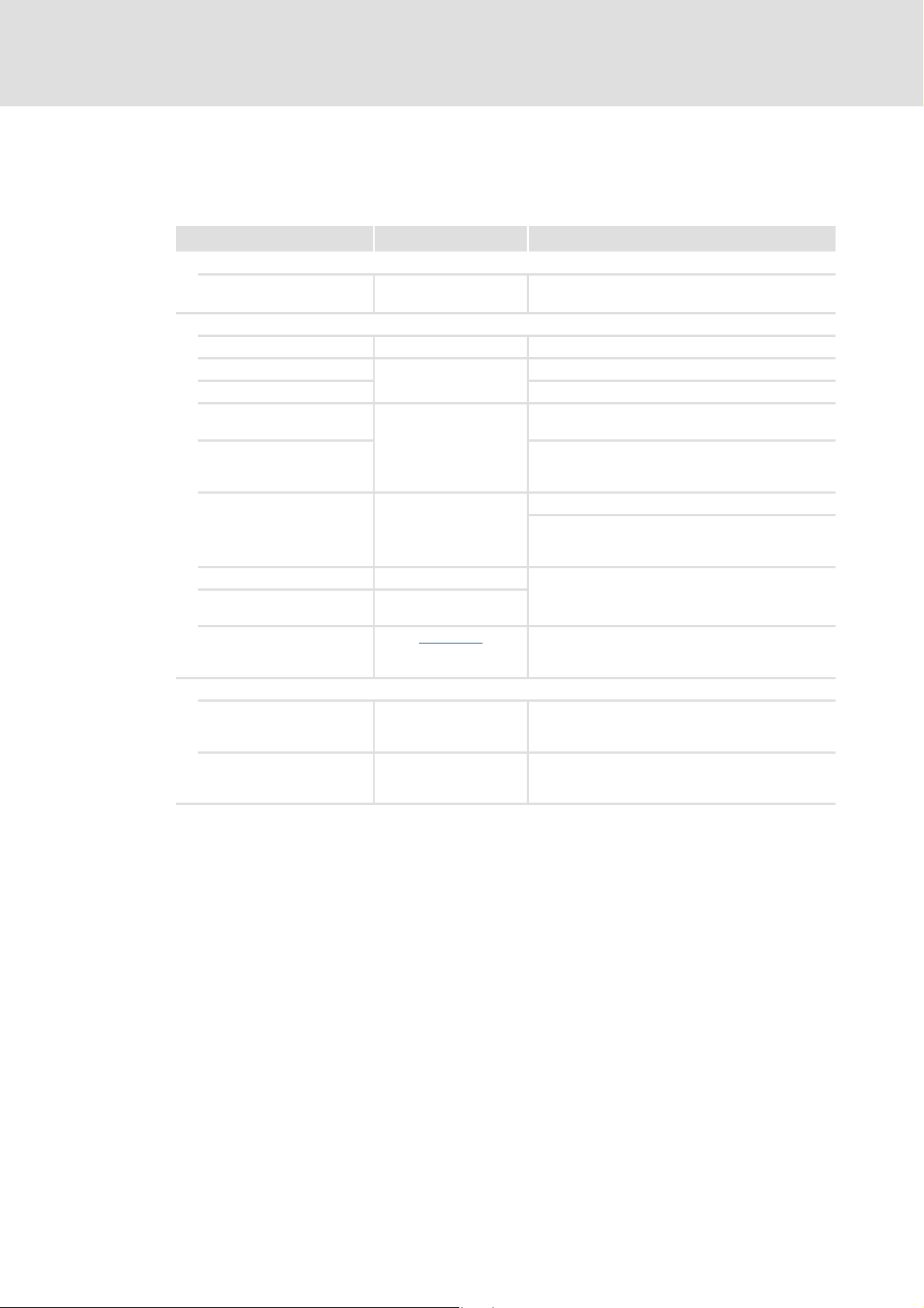
1.1 Conventions used
This documentation uses the following conventions to distinguish between different types
of information:
Type of information Writing Examples/notes
Numbers
Decimal separator Point The decimal point is always used.
Text
Program name » « The Lenze PC software »PLC Designer«...
Window Italics The Message window ... / The Options dialog box...
Variable identifier By setting bEnable to TRUE...
Control element Bold The OK button... / The copy command... / The
Sequence of menu
commands
Shortcut <Bold> Press <F1> to open the online help.
Program code Courier
Keyword Courier bold
Example: 1234.56
Properties tab... / The Name input field...
If several commands must be used in sequence to
carry out a function, then the individual commands
are separated by an arrow: Select File
If a key combination is required for a command, a "+"
is inserted between the key identifiers: Use
<Shift>+<ESC>...
IF var1 < var2 THEN
a = a + 1
END IF
Open to...
Hyperlink Underlined
Symbols
Page reference ( 4) Optically highlighted reference to another page. It is
Step-by-step instructions
Optically highlighted reference to another topic. It is
activated with a mouse click in this online
documentation.
activated with a mouse click in this online
documentation.
Step-by-step instructions are indicated by a
pictograph.
4 L DMS 1.0 EN - 07/2011 - TD05
Page 5

1.2 Definition of notes used
The following signal words and symbols are used in this documentation to indicate
dangers and important information:
Safety instructions
Layout of the safety instructions:
Danger!
(characterises the type and severity of danger)
Note
(describes the danger and gives information about how to prevent dangerous
situations)
Function library "CANopenSdoDrv"
About this documentation
Definition of notes used
Pictograph Signal word Meaning
Danger! Danger of personal injury through dangerous electrical voltage
Danger! Danger of personal injury through a general source of danger
Stop! Danger of property damage
Application notes
Pictograph Signal word Meaning
Note! Important note to ensure trouble-free operation
Reference to an imminent danger that may result in death or serious personal
injury if the corresponding measures are not taken.
Reference to an imminent danger that may result in death or serious personal
injury if the corresponding measures are not taken.
Reference to a possible danger that may result in property damage if the
corresponding measures are not taken.
Tip! Useful tip for simple handling
Reference to another document
DMS 1.0 EN - 07/2011 - TD05 L 5
Page 6

Function library "CANopenSdoDrv"
System requirements
2 System requirements
Software
The function library can be used with the following Lenze software:
Product Type designation Version
Drive PLC Developer Studio ESP-DDS2-x 2.x
Supported target systems
Product range Type designation Hardware version From software version
Drive PLC EPL-10200 1A or higher 2.x
9300 Servo PLC EVS93xx-EI
EVS93xx-ET
ECS ECSxA 1A or higher 6.x
1A or higher 2.x
Required libraries
Unless already available, insert the following libraries into the library management (menu
WindowLibrary management):
Standard.lib
CANopenSdoDrvV10.lib
LenzeCanDrvVxxxx.lib
Initialisation of the CAN driver
For using the free PDOs, an initialisation of the CAN driver with the L_CanInit function call
is required. This function must only be called once. Thus, best use the system POU
"PLC_ColdStart" for calling this function.
The CAN interface of the PLC target system (e.g. 9300 Servo PLC) must be in the
"Operational" status.
6 L DMS 1.0 EN - 07/2011 - TD05
Page 7

3 Basics - Service Data Objects (SDOs)
"Service Data Objects" (abbreviated with SDOs) serve to exchange data of any length and
data type between two CAN nodes. The exchange takes place according to the client server
model:
As an "SDO client", a CAN node accesses data of a the other CAN node ("SDO server) by
writing (download) or reading (upload). This data is located in the object directory of the
SDO server and is addressed by the SDO client via the given index and subindex. Each
access of the SDO client will be acknowledged by the SDO server.
The connection between the SDO client and the SDO server is also called parameter
channel. Each CANopen node must at least support one parameter channel ("default SDO")
to be accessible for other nodes. For Lenze devices, it is the parameter channel 1.
As a CAN telegram can only transmit 8 bytes, SDOs are typically transmitted in a sequence
of segments. For initialising the data transfer, the SDO client first sends a telegram to the
SDO server in which the SDO server is instructed in which way (reading/writing) it is to
access which index/subindex of the SDO server. The acknowledgement of the telegram by
the SDO server completes the initialisation phase and the segmented transmission of the
data starts.
Function library "CANopenSdoDrv"
Basics - Service Data Objects (SDOs)
Addressing through index and subindex
If only up to 4 bytes of data are to be transferred, the reduced transfer ("expedited
transfer") can be used as well. In this transfer mode, the data is already transferred during
the initialisation phase with the first telegram.
The reduced transfer ("expedited transfer") must be supported by the SDO client and the
SDO server according to the CANopen specification. It is switched to the segmented
transfer if more than 4 bytes of data must be transferred.
The least-significant byte (LSB) of the CAN telegram is reserved for the command. Among
other things, the command contains information on the access type (writing/reading) and
the transfer type (segmented/expedited).
3.1 Addressing through index and subindex
The parameters or Lenze codes are addressed according to the following formula:
Index = 24575 – (Lenze code number + 2000 (parameter set – 1))
Example:
The acceleration time (code C1312) in the parameter set 2 is to be addressed. This code has
the subindex 0 (no subindex).
Calculation:
Index = 24575 – 12 – 2000 = 22563 = 5823hex
Subindex = 0
Tip!
For converting a code number into the required CAN index, you can use the
L_FUNCodeIndexConv function from the »LenzeDrive.lib« library.
DMS 1.0 EN - 07/2011 - TD05 L 7
Page 8

Function library "CANopenSdoDrv"
Basics - Service Data Objects (SDOs)
SDO services
3.2 SDO services
The following services can be used for SDOs:
SDO download
With this service, the SDO client transfers data to the SDO server. The SDO client reports to
the SDO server which and how much data is to be transmitted to which address (index,
subindex). This service is acknowledged by the SDO server.
The SDO download consists at least of the following services:
Initialisation:
SDO client prepares SDO server for download.
Segmented download:
SDO client transmits the data segments to the SDO server.
(Optional, only if the data size is > 4 bytes.)
SDO upload
With this service, the SDO server transfers data to the SDO client. The SDO client reports to
the SDO server which address (index, subindex) is to be used to upload the data.
The SDO upload consists at least of the following services:
Initialisation:
SDO client prepares SDO server for upload.
Segmented upload:
SDO server transmits the required data segments to the SDO client.
(Optional, only if the data size is > 4 Byte.)
SDO abort
Abort of the SDO transfer. The reason for the abort is given optionally.
8 L DMS 1.0 EN - 07/2011 - TD05
Page 9

4 Function blocks
Function block Function
IndexRead
IndexWrite
BlockRead
BlockWrite
Function library "CANopenSdoDrv"
Function blocks
Read CAN index
• The block uses the reduced SDO upload ("expedited transfer").
Write CAN index
• The block uses the reduced SDO download ("expedited transfer").
Read CAN index
• The block uses the segmented SDO upload.
Write CAN index
• The block uses the segmented SDO download.
DMS 1.0 EN - 07/2011 - TD05 L 9
Page 10

Function library "CANopenSdoDrv"
Function blocks
IndexRead - read CAN index
4.1 IndexRead - read CAN index
Call possible in: ; Cyclic task
Interrupt task
; Time-controlled task (INTERVAL)
Event-controlled task (EVENT)
This FB serves to read parameters (CAN indexes) of other devices via system bus (CAN). The
block uses the reduced SDO upload ("expedited transfer").
nAddress serves to select the corresponding node where the SDO access is to take place.
At the same time, the parameter channel to be used (SDO1 or SDO2) is selected at the
node via nAddress.
Note!
• The FB must be called cyclically in order that the response to the write request
("read response") is detected. Typically, the response arrives only some
program cycles later.
• Make sure that several nodes do not execute an SDO access a node at the
same time via the same parameter channel, since this "collision" would cause
the system bus (CAN) to change to the "bus off" status.
• Do not start several SDO accesses to the same node at the same time. This
causes an incorrect evaluation of the node response.
• Do not use the FBs from the "CANopenSdoDrv.lib" library and the FBs
L_ParWrite and L_ParRead from the "LenzeDrive.lib" library at the same time.
IndexRead
⎯ bExecute bDone ⎯
⎯ nAddress bBusy ⎯
⎯ nIndex nIndexSize ⎯
⎯ nSubIndex dnValue ⎯
⎯ tRxTimeout bError ⎯
dnErrorNo ⎯
10 L DMS 1.0 EN - 07/2011 - TD05
Page 11

Inputs
Identifier/data type Information/possible settings
bExecute
nAddress
nIndex
nSubIndex
tRxTimeout
FALSEÊTRUE Activates a read request
BOOL
CAN node address
INT
INT
INT
TIME
1 ... 63 Parameter channel 1
65 ... 127 Parameter channel 2
CAN index
• For converting a code number into the required CAN index, you can use the
L_FUNCodeIndexConv function from the »LenzeDrive.lib« library.
CAN subindex
TimeOut time
• After the read request has been sent, the FB must receive a response from the
target device within this time. Otherwise, a timeout error will be output.
• If the input is not connected, the timeout time is one second.
Function library "CANopenSdoDrv"
Function blocks
IndexRead - read CAN index
Outputs
Identifier/data type Value/meaning
bDone
bBusy
nIndexSize
dnValue
bError
BOOL
BOOL
Size of the data type of the read CAN index
INT
Value of the read CAN index
DINT
BOOL
TRUE Request executed successfully
TRUE Request in process
TRUE An error has occurred during job execution
• bDone is set to TRUE for at least one processing cycle.
• bDone will only be reset to FALSE if the bExecute input is set to
FALSE as well.
• For details see dnErrorNo.
• bError is set to TRUE for at least one processing cycle.
• bError will only be reset to FALSE if the bExecute input is set to
FALSE as well.
DMS 1.0 EN - 07/2011 - TD05 L 11
Page 12

Function library "CANopenSdoDrv"
Function blocks
IndexRead - read CAN index
Identifier/data type Value/meaning
dnErrorNo
Error number
DINT
> 0 For meaning, see chapter "Error numbers
-1 TimeOut – no response received
Remedy:
-2 Response of station does not correspond to read request
-1011 Internal data pointer does not stand on the PLC RAM
-1012 The set CAN identifier (COB-ID) is outside the permissible range
(0…2047)
Remedy:
nAddress input.
-1118 No free CAN channel is available.
Remedy:o
• Do not use one of the CAN objects CAN1_IN … CAN3_IN or
• Set C2118 to "1" (write parameter via SDO2).
• Switch off the generation of the sync object (C0369=0).
-1119 The transmit request memory is full. The transmit request could not
be entered anymore.
Remedy:
• Reduce the number of transmit objects.
• Increase the cycle time of the transmission objects.
• Increase baud rate.
Generally, an object is sent every 250 μs.
-1120 CAN driver is not initialised
Remedy:
the »LenzeCanDrv.lib« library.
-1121 Wrong driver number
-1150 CAN bus is not in the "Operational" status
Remedy:
PLC target system as master (C0352=1).
-2011 Internal data pointer does not stand on the PLC RAM
-2012 The set CAN identifier (COB-ID) is outside the permissible range
(0…2047)
Remedy:
nAddress input.
-2120 CAN driver is not initialised
Remedy:
the »LenzeCanDrv.lib« library.
-2121 Wrong driver number
-2150 CAN bus is not in the "Operational" status
Remedy:
PLC target system as master (C0352=1).
Increase the set timeout time at the tRxTimeout input.
Assign a CAN node address between 1 and 127 to the
CAN1_OUT … CAN3_OUT.
Note: If C2118 = "1", the SDO2 channel is not available anymore!
Initialise the CAN driver with the L_CanInit function from
Configure the system bus interface "CAN on board" of the
Assign a CAN node address between 1 and 127 to the
Initialise the CAN driver with the L_CanInit function from
Configure the system bus interface "CAN on board" of the
". ( 22)
12 L DMS 1.0 EN - 07/2011 - TD05
Page 13

4.2 IndexWrite - write CAN index
Function library "CANopenSdoDrv"
Function blocks
IndexWrite - write CAN index
Call possible in: ; Cyclic task
Interrupt task
; Time-controlled task (INTERVAL)
Event-controlled task (EVENT)
This FB serves to write parameters (CAN indexes) of other devices via system bus (CAN).
The block uses the reduced SDO download ("expedited transfer").
nAddress serves to select the corresponding node where the SDO access is to take place.
A the same time, the parameter channel to be used (SDO1 or SDO2) is selected at the
node via nAddress.
Note!
• The FB must be called cyclically in order that the response to the write request
("write response") is detected. Typically, the response arrives only some
program cycles later.
• Make sure that several nodes do not execute an SDO access a node at the
same time via the same parameter channel, since this "collision" would cause
the system bus (CAN) to change to the "bus off" status.
• Do not start several SDO accesses to the same node at the same time. This
causes an incorrect evaluation of the node response.
• Do not use the FBs from the "CANopenSdoDrv.lib" library and the FBs
L_ParWrite and L_ParRead from the "LenzeDrive.lib" library at the same time.
IndexWrite
⎯ bExecute bDone ⎯
⎯ nAddress bBusy ⎯
⎯ nIndex bError ⎯
⎯ nSubIndex dnErrorNo ⎯
⎯ nIndexSize
⎯ tRxTimeout
⎯ dnValue
DMS 1.0 EN - 07/2011 - TD05 L 13
Page 14

Function library "CANopenSdoDrv"
Function blocks
IndexWrite - write CAN index
Inputs
Identifier/data type Information/possible settings
bExecute
nAddress
nIndex
nSubIndex
nIndexSize
tRxTimeout
dnValue
FALSEÊTRUE Activate a write request
BOOL
CAN node address
INT
INT
INT
INT
TIME
DINT
1 ... 63 Parameter channel 1
65 ... 127 Parameter channel 2
CAN index
• For converting a code number into the required CAN index, you can use the
L_FUNCodeIndexConv function from the »LenzeDrive.lib« library.
CAN subindex
Size of the data type of the CAN index to be written
• Permissible values: 1, 2 or 4 [Byte]
TimeOut time
• After the write request has been sent, the FB must receive a response from the
target device within this time. Otherwise, a timeout error will be output.
• If the input is not connected, the timeout time is one second.
Value to be written
Outputs
Identifier/data type Value/meaning
bDone
BOOL
bBusy
BOOL
bError
BOOL
TRUE Request executed successfully
• bDone is set to TRUE for at least one processing cycle.
• bDone will only be reset to FALSE if the bExecute input is set to
FALSE as well.
TRUE Request in process
TRUE An error has occurred during job execution
• For details see dnErrorNo.
• bError is set to TRUE for at least one processing cycle.
• bError will only be reset to FALSE if the bExecute input is set to
FALSE as well.
14 L DMS 1.0 EN - 07/2011 - TD05
Page 15

Identifier/data type Value/meaning
dnErrorNo
DINT
Error number
> 0 For meaning, see chapter "Error numbers
-1 TimeOut – no response received
-2 Response of station does not correspond to write request
-3 Value at the nIndexSize input is not correct
-1011 Internal data pointer does not stand on the PLC RAM
-1012 The set CAN identifier (COB-ID) is outside the permissible range
-1118 No free CAN channel is available.
-1119 The transmit request memory is full. The transmit request could not
-1120 CAN driver is not initialised
-1121 Wrong driver number
-1150 CAN bus is not in the "Operational" status
-2011 Internal data pointer does not stand on the PLC RAM
-2012 The set CAN identifier (COB-ID) is outside the permissible range
-2120 CAN driver is not initialised
-2121 Wrong driver number
-2150 CAN bus is not in the "Operational" status
Function library "CANopenSdoDrv"
Function blocks
IndexWrite - write CAN index
". ( 22)
Remedy:
Remedy:
(0…2047)
Remedy:
nAddress input.
Remedy:
• Do not use one of the CAN objects CAN1_IN … CAN3_IN or
• Set C2118 to "1" (write parameter via SDO2).
• Switch off the generation of the sync object (C0369=0).
be entered anymore.
Remedy:
• Reduce the number of transmit objects.
• Increase the cycle time of the transmission objects.
• Increase baud rate.
Generally, an object is sent every 250 μs.
Remedy:
the »LenzeCanDrv.lib« library.
Remedy:
PLC target system as master (C0352=1).
(0…2047)
Remedy:
nAddress input.
Remedy:
the »LenzeCanDrv.lib« library.
Remedy:
PLC target system as master (C0352=1).
Increase the set timeout time at the tRxTimeout input.
Select the value 1, 2 or 4 [Byte] as data type size.
Assign a CAN node address between 1 and 127 to the
CAN1_OUT … CAN3_OUT.
Note: If C2118 = "1", the SDO2 channel is not available anymore!
Initialise the CAN driver with the L_CanInit function from
Configure the system bus interface "CAN on board" of the
Assign a CAN node address between 1 and 127 to the
Initialise the CAN driver with the L_CanInit function from
Configure the system bus interface "CAN on board" of the
DMS 1.0 EN - 07/2011 - TD05 L 15
Page 16

Function library "CANopenSdoDrv"
Function blocks
BlockRead - read CAN index per segmented data transfer
4.3 BlockRead - read CAN index per segmented data transfer
Call possible in: ; Cyclic task
Interrupt task
; Time-controlled task (INTERVAL)
Event-controlled task (EVENT)
This FB serves to read parameters (CAN indexes) of other devices via system bus (CAN). The
block uses the segmented SDO upload.
nAddress serves to select the corresponding node where the SDO access is to take place.
A the same time, the parameter channel to be used (SDO1 or SDO2) is selected at the
node via nAddress.
Note!
• The FB must be called cyclically in order that the response to the write request
("read response") is detected. Typically, the response arrives only some
program cycles later.
• Make sure that several nodes do not execute an SDO access a node at the
same time via the same parameter channel, since this "collision" would cause
the system bus (CAN) to change to the "bus off" status.
• Do not start several SDO accesses to the same node at the same time. This
causes an incorrect evaluation of the node response.
• Do not use the FBs from the "CANopenSdoDrv.lib" library and the FBs
L_ParWrite and L_ParRead from the "LenzeDrive.lib" library at the same time.
BlockRead
⎯ bExecute bDone ⎯
⎯ nAddress bBusy ⎯
⎯ nIndex nIndexSize ⎯
⎯ nSubIndex bError ⎯
⎯ tRxTimeout dnErrorNo ⎯
⎯ nBufferSize
⎯ pData
16 L DMS 1.0 EN - 07/2011 - TD05
Page 17

BlockRead - read CAN index per segmented data transfer
Inputs
Identifier/data type Information/possible settings
bExecute
nAddress
nIndex
nSubIndex
tRxTimeout
nBufferSize
pData
POINTER
FALSEÊTRUE Activates a read request
BOOL
CAN node address
INT
INT
INT
TIME
INT
1 ... 63 Parameter channel 1
65 ... 127 Parameter channel 2
CAN index
• For converting a code number into the required CAN index, you can use the
L_FUNCodeIndexConv function from the »LenzeDrive.lib« library.
CAN subindex
TimeOut time
• After the read request has been sent, the FB must receive a response from the
target device within this time. Otherwise, a timeout error will be output.
• If the input is not connected, the timeout time is one second.
Maximum number of the data bytes that are allowed to be received as a function of
the size of the variables created at the pData.
Pointer to the address of the memory area for storing the received data bytes.
• The address of a variable can be determined with the address function ADR.
Function library "CANopenSdoDrv"
Function blocks
Outputs
Identifier/data type Value/meaning
bDone
bBusy
nIndexSize
bError
BOOL
BOOL
Size of the data type of the read CAN index or number of the received data bytes.
INT
BOOL
TRUE Request executed successfully
TRUE Request in process
TRUE An error has occurred during job execution
• bDone is set to TRUE for at least one processing cycle.
• bDone will only be reset to FALSE if the bExecute input is set to
FALSE as well.
• For details see dnErrorNo.
• bError is set to TRUE for at least one processing cycle.
• bError will only be reset to FALSE if the bExecute input is set to
FALSE as well.
DMS 1.0 EN - 07/2011 - TD05 L 17
Page 18

Function library "CANopenSdoDrv"
Function blocks
BlockRead - read CAN index per segmented data transfer
Identifier/data type Value/meaning
dnErrorNo
DINT
Error number
> 0 For meaning, see chapter "Error numbers
-1 TimeOut – no response received
Remedy:
-2 Response of station does not correspond to read request
-4 Number of the received data bytes does not correspond to the
number of the expected data bytes.
-5 Number of the expected data bytes is higher than the value given at
the nBufferSize input.
Remedy:
• Increase the value at the nBufferSize input.
• Make sure that the variable at the pData input has at least the
-6 Toggle bit in the SDO response has not changed its value.
-1011 Internal data pointer does not stand on the PLC RAM
-1012 The set CAN identifier (COB-ID) is outside the permissible range
(0…2047)
Remedy:
nAddress input.
-1118 No free CAN channel is available.
Remedy:
• Do not use one of the CAN objects CAN1_IN … CAN3_IN or
• Set C2118 to "1" (write parameter via SDO2).
• Switch off the generation of the sync object (C0369=0).
-1119 The transmit request memory is full. The transmit request could not
be entered anymore.
Remedy:
• Reduce the number of transmit objects.
• Increase the cycle time of the transmission objects.
• Increase baud rate.
Generally, an object is sent every 250 μs.
-1120 CAN driver is not initialised
Remedy:
the »LenzeCanDrv.lib« library.
-1121 Wrong driver number
-1150 CAN bus is not in the "Operational" status
Remedy:
PLC target system as master (C0352=1).
-2011 Internal data pointer does not stand on the PLC RAM
-2012 The set CAN identifier (COB-ID) is outside the permissible range
(0…2047)
Remedy:
nAddress input.
-2120 CAN driver is not initialised
Remedy:
the »LenzeCanDrv.lib« library.
-2121 Wrong driver number
-2150 CAN bus is not in the "Operational" status
Remedy:
PLC target system as master (C0352=1).
". ( 22)
Increase the set timeout time at the tRxTimeout input.
same value as the value at the nBufferSize input.
Assign a CAN node address between 1 and 127 to the
CAN1_OUT … CAN3_OUT.
Note: If C2118 = "1", the SDO2 channel is not available anymore!
Initialise the CAN driver with the L_CanInit function from
Configure the system bus interface "CAN on board" of the
Assign a CAN node address between 1 and 127 to the
Initialise the CAN driver with the L_CanInit function from
Configure the system bus interface "CAN on board" of the
18 L DMS 1.0 EN - 07/2011 - TD05
Page 19

Function library "CANopenSdoDrv"
BlockWrite - write CAN index per segmented data transfer
4.4 BlockWrite - write CAN index per segmented data transfer
Function blocks
Call possible in: ; Cyclic task
Interrupt task
; Time-controlled task (INTERVAL)
Event-controlled task (EVENT)
This FB serves to write parameters (CAN indexes) of other devices via system bus (CAN).
The block uses the segmented SDO download.
nAddress serves to select the corresponding node where the SDO access is to take place.
A the same time, the parameter channel to be used (SDO1 or SDO2) is selected at the
node via nAddress.
Note!
• The FB must be called cyclically in order that the response to the write request
("write response") is detected. Typically, the response arrives only some
program cycles later.
• Make sure that several nodes do not execute an SDO access a node at the
same time via the same parameter channel, since this "collision" would cause
the system bus (CAN) to change to the "bus off" status.
• Do not start several SDO accesses to the same node at the same time. This
causes an incorrect evaluation of the node response.
• Do not use the FBs from the "CANopenSdoDrv.lib" library and the FBs
L_ParWrite and L_ParRead from the "LenzeDrive.lib" library at the same time.
IndexWrite
⎯ bExecute bDone ⎯
⎯ nAddress bBusy ⎯
⎯ nIndex bError ⎯
⎯ nSubIndex dnErrorNo ⎯
⎯ tRxTimeout
⎯ nIndexSize
⎯ pData
DMS 1.0 EN - 07/2011 - TD05 L 19
Page 20

Function library "CANopenSdoDrv"
Function blocks
BlockWrite - write CAN index per segmented data transfer
Inputs
Identifier/data type Information/possible settings
bExecute
nAddress
nIndex
nSubIndex
tRxTimeout
nIndexSize
pData
POINTER
FALSEÊTRUE Activate a write request
BOOL
CAN node address
INT
INT
INT
TIME
INT
1 ... 63 Parameter channel 1
65 ... 127 Parameter channel 2
CAN index
• For converting a code number into the required CAN index, you can use the
L_FUNCodeIndexConv function from the »LenzeDrive.lib« library.
CAN subindex
TimeOut time
• After the write request has been sent, the FB must receive a response from the
target device within this time. Otherwise, a timeout error will be output.
• If the input is not connected, the timeout time is one second.
Number of data bytes to be sent
Pointer to the address of the memory area for storing the data bytes to be sent.
• The address of a variable can be determined with the address function ADR.
Outputs
Identifier/data type Value/meaning
bDone
BOOL
bBusy
BOOL
bError
BOOL
TRUE Request executed successfully
• bDone is set to TRUE for at least one processing cycle.
• bDone will only be reset to FALSE if the bExecute input is set to
FALSE as well.
TRUE Request in process
TRUE An error has occurred during job execution
• For details see dnErrorNo.
• bError is set to TRUE for at least one processing cycle.
• bError will only be reset to FALSE if the bExecute input is set to
FALSE as well.
20 L DMS 1.0 EN - 07/2011 - TD05
Page 21

BlockWrite - write CAN index per segmented data transfer
Identifier/data type Value/meaning
dnErrorNo
DINT
Error number
> 0 For meaning, see chapter "Error numbers
-1 TimeOut – no response received
-2 Response of station does not correspond to write request
-3 Value at the nIndexSize input is higher than 255
-6 Toggle bit in the SDO response has not changed its value.
-1011 Internal data pointer does not stand on the PLC RAM
-1012 The set CAN identifier (COB-ID) is outside the permissible range
-1118 No free CAN channel is available.
-1119 The transmit request memory is full. The transmit request could not
-1120 CAN driver is not initialised
-1121 Wrong driver number
-1150 CAN bus is not in the "Operational" status
-2011 Internal data pointer does not stand on the PLC RAM
-2012 The set CAN identifier (COB-ID) is outside the permissible range
-2120 CAN driver is not initialised
-2121 Wrong driver number
-2150 CAN bus is not in the "Operational" status
Function library "CANopenSdoDrv"
Function blocks
". ( 22)
Remedy:
(0…2047)
Remedy:
nAddress input.
Remedy:
• Do not use one of the CAN objects CAN1_IN … CAN3_IN or
• Set C2118 to "1" (write parameter via SDO2).
• Switch off the generation of the sync object (C0369=0).
be entered anymore.
Remedy:
• Reduce the number of transmit objects.
• Increase the cycle time of the transmission objects.
• Increase baud rate.
Generally, an object is sent every 250 μs.
Remedy:
the »LenzeCanDrv.lib« library.
Remedy:
PLC target system as master (C0352=1).
(0…2047)
Remedy:
nAddress input.
Remedy:
the »LenzeCanDrv.lib« library.
Remedy:
PLC target system as master (C0352=1).
Increase the set timeout time at the tRxTimeout input.
Assign a CAN node address between 1 and 127 to the
CAN1_OUT … CAN3_OUT.
Note: If C2118 = "1", the SDO2 channel is not available anymore!
Initialise the CAN driver with the L_CanInit function from
Configure the system bus interface "CAN on board" of the
Assign a CAN node address between 1 and 127 to the
Initialise the CAN driver with the L_CanInit function from
Configure the system bus interface "CAN on board" of the
DMS 1.0 EN - 07/2011 - TD05 L 21
Page 22

Function library "CANopenSdoDrv"
Error numbers
5 Error numbers
The following error numbers are specified according to CANopen:
Error number (hex) Explanation
0503 0000 Toggle bit not changed
0504 0000 SDO protocol expired
0504 0001 Invalid or unknown client/server command specifier
0504 0002 Invalid block size (block mode only)
0504 0003 Invalid processing number (block mode only)
0504 0004 CRC error (block mode only)
0504 0005 Memory does not suffice
0601 0001 Attempted read access to a writable only object
0601 0002 Attempted write access to a readable only object.
0602 0000 Object not listed in object directory
0604 0041 Object not mapped to PDO
0604 0042 Number and length of objects to be transferred longer than PDO
0604 0043 General parameter incompatibility
0604 0047 General internal device incompatibility
0606 0000 Access denied because of hardware error
0607 0010 Unsuitable data type (unsuitable service parameter length)
0607 0012 Unsuitable data type (service parameter length exceeded)
0607 0013 Unsuitable data type (service parameter length too short)
0609 0011 Subindex does not exist
0609 0030 Parameter value range exceeded
0609 0031 Parameter values too high
0609 0032 Parameter values too low
0609 0036 Maximum value falls below minimum value
0800 0000 General fault
0800 0020 Data cannot be transferred or saved to application
0800 0021 Data cannot be transferred or saved to application due to local control
0800 0022 Data cannot be transferred or saved to application due to the current device status
0800 0023 Dynamic generation of object directory failed or no object directory available (e.g.
object directory generated from file, generation not possible because of a file error)
In addition, the following error numbers are specified for the Lenze system bus:
Error number (hex) Explanation
0606 0010 Index does not exist
0605 0010 Subindex does not exist
0603 0010 Access denied
22 L DMS 1.0 EN - 07/2011 - TD05
Page 23

6Index
A
Application notes 5
B
BlockRead 16
BlockWrite 19
C
CAN driver 6
D
Document history 3
E
E-mail to Lenze 24
F
Feedback to Lenze 24
Function library "CANopenSdoDrv"
Index
I
IndexRead 10
IndexWrite 13
L
Layout of the safety information 5
Layout of the safety instructions 5
S
Safety instructions 5
V
Validity information 3
Version identifier of the function library 3
DMS 1.0 EN - 07/2011 - TD05 L 23
Page 24

Your opinion is important to us
)(('%$&.
These instructions were created to the best of our knowledge
and belief to give you the best possible support for handling
our product.
Perhaps we have not always succeeded in achieving this goal.
If you notice this, please send us your suggestions and
criticism in a short e-mail to:
feedback-docu@Lenze.de
Thank you for your support.
Your Lenze documentation team
24 L
Page 25

L 25
Page 26

)
¬
|
Þ
© 07/2011
Lenze Automation GmbH
Hans-Lenze-Str. 1
D-31855 Aerzen
Germany
+49 (0)51 54 / 82-0
+49 (0)51 54 / 82-28 00
Lenze@Lenze.de
www.Lenze.com
Service Lenze Service GmbH
Breslauer Straße 3
D-32699 Extertal
Germany
¬
|
00 80 00 / 24 4 68 77 (24 h helpline)
+49 (0)51 54 / 82-11 12
Service@Lenze.de
EDSPLCLIB03 13384448 EN 1.0 TD05
10 9 8 7 6 5 4 3 2 1
 Loading...