

Page 1
EDKZN3B024
.Oe$
Ä.Oe$ä
Montageanleitung
Mounting Instructions
Instructions de montage
Global Drive 1.5 ... 24 A
EZN3B2400H002, EZN3B1500H003,
EZN3B0900H004, EZN3B0750H005,
EZN3B0500H007, EZN3B0400H009,
EZN3B0300H013, EZN3B0250H015,
EZN3B0150H024
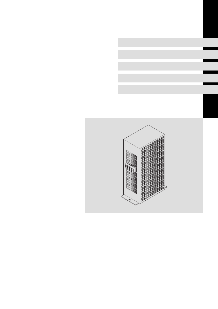
Netzfilter
Mains filter
Filtre réseau
l
Page 2

, Lesen Sie zuerst diese Anleitung und die Dokumentation zum
Grundgerät, bevor Sie mit den Arbeiten beginnen!
Beachten Sie die enthaltenen Sicherheitshinweise.
, Please read these instructions and the documentation of the standard
device before you start working!
Observe the safety instructions given therein!
, Lire le présent fascicule et la documentation relative à l’appareil de base
avant toute manipulation de l’équipement !
Respecter les consignes de sécurité fournies.
Page 3

Inhalt i
1 Über diese Dokumentation 4. . . . . . . . . . . . . . . . . . . . . . . . . . . . . . . . . . . . . . . . .
1.1 Informationen zur Gültigkeit 4. . . . . . . . . . . . . . . . . . . . . . . . . . . . . . . . .
1.2 Zielgruppe 4. . . . . . . . . . . . . . . . . . . . . . . . . . . . . . . . . . . . . . . . . . . . . . . .
1.3 Dokumenthistorie 5. . . . . . . . . . . . . . . . . . . . . . . . . . . . . . . . . . . . . . . . . .
1.4 Verwendete Konventionen 5. . . . . . . . . . . . . . . . . . . . . . . . . . . . . . . . . . .
1.5 Verwendete Hinweise 6. . . . . . . . . . . . . . . . . . . . . . . . . . . . . . . . . . . . . . .
2 Sicherheitshinweise 7. . . . . . . . . . . . . . . . . . . . . . . . . . . . . . . . . . . . . . . . . . . . . . .
2.1 Allgemeine Sicherheitshinweise 7. . . . . . . . . . . . . . . . . . . . . . . . . . . . . .
2.2 Restgefahren 8. . . . . . . . . . . . . . . . . . . . . . . . . . . . . . . . . . . . . . . . . . . . . .
3 Produktbeschreibung 10. . . . . . . . . . . . . . . . . . . . . . . . . . . . . . . . . . . . . . . . . . . . .
3.1 Bestimmungsgemäße Verwendung 10. . . . . . . . . . . . . . . . . . . . . . . . . . .
3.2 Zuordnung Filter − Grundgerät 10. . . . . . . . . . . . . . . . . . . . . . . . . . . . . . . .
3.3 Lieferumfang 11. . . . . . . . . . . . . . . . . . . . . . . . . . . . . . . . . . . . . . . . . . . . . .
3.4 Übersicht 11. . . . . . . . . . . . . . . . . . . . . . . . . . . . . . . . . . . . . . . . . . . . . . . . .
3.5 Identifikation 12. . . . . . . . . . . . . . . . . . . . . . . . . . . . . . . . . . . . . . . . . . . . . .
4 Technische Daten 13. . . . . . . . . . . . . . . . . . . . . . . . . . . . . . . . . . . . . . . . . . . . . . . . .
4.1 Allgemeine Daten und Einsatzbedingungen 13. . . . . . . . . . . . . . . . . . . .
4.2 Bemessungsdaten 15. . . . . . . . . . . . . . . . . . . . . . . . . . . . . . . . . . . . . . . . . .
4.3 Mechanische Daten 16. . . . . . . . . . . . . . . . . . . . . . . . . . . . . . . . . . . . . . . .
5 Mechanische Installation 18. . . . . . . . . . . . . . . . . . . . . . . . . . . . . . . . . . . . . . . . . . .
5.1 Wichtige Hinweise 18. . . . . . . . . . . . . . . . . . . . . . . . . . . . . . . . . . . . . . . . . .
5.2 Bohrplan 19. . . . . . . . . . . . . . . . . . . . . . . . . . . . . . . . . . . . . . . . . . . . . . . . . .
5.3 Montageschritte 20. . . . . . . . . . . . . . . . . . . . . . . . . . . . . . . . . . . . . . . . . . .
6 Elektrische Installation 21. . . . . . . . . . . . . . . . . . . . . . . . . . . . . . . . . . . . . . . . . . . . .
6.1 Wichtige Hinweise 21. . . . . . . . . . . . . . . . . . . . . . . . . . . . . . . . . . . . . . . . . .
6.2 Anschlussplan 22. . . . . . . . . . . . . . . . . . . . . . . . . . . . . . . . . . . . . . . . . . . . .
6.3 Anschlussdaten 23. . . . . . . . . . . . . . . . . . . . . . . . . . . . . . . . . . . . . . . . . . . .
6.4 Montageschritte 23. . . . . . . . . . . . . . . . . . . . . . . . . . . . . . . . . . . . . . . . . . .
EDKZN3B024 DE/EN/FR 3.0
l
3
Page 4

1
Über diese Dokumentation
Informationen zur Gültigkeit
1 Über diese Dokumentation
0Abb. 0Tab. 0
1.1 Informationen zur Gültigkeit
Diese Anleitung ist gültig für
ƒ Netzfilter EZN3B2400H002
ƒ Netzfilter EZN3B1500H003
ƒ Netzfilter EZN3B0900H004
ƒ Netzfilter EZN3B0750H005
ƒ Netzfilter EZN3B0500H007
ƒ Netzfilter EZN3B0400H009
ƒ Netzfilter EZN3B0300H013
ƒ Netzfilter EZN3B0250H015
ƒ Netzfilter EZN3B0150H024
1.2 Zielgruppe
Diese Dokumentation richtet sich an qualifiziertes Fachpersonal nach
IEC 60364.
Qualifiziertes Fachpersonal sind Personen, die für die auszuführenden Tätigkeiten bei der Aufstellung, Montage, Inbetriebsetzung und dem Betrieb des Produkts über entsprechende Qualifikationen verfügen.
I Tip!
Informationen und Hilfsmittel rund um die Lenze−Produkte finden
Sie im Download−Bereich unter
www.lenze.com
4
l
EDKZN3B024 DE/EN/FR 3.0
Page 5

1.3 Dokumenthistorie
Materialnummer Version Beschreibung
.Oe$ 3.0 09/2014 TD29 EAC−Konformität
13336826 2.1 11/2011 TD00 Überarbeitung
13336826 2.0 04/2010 TD29 Neuauflage wegen Neuorganisation des Un-
13216453 1.0 10/2007 TD29 Erstausgabe
1.4 Verwendete Konventionen
Informationsart Auszeichnung Beispiele/Hinweise
Zahlenschreibweise
Dezimaltrennzeichen
Warnhinweise
UL−Warnhinweise
UR−Warnhinweise
Textauszeichnung
Programmname » « PC−Software
Symbole
Seitenverweis ^ Verweis auf eine andere Seite mit
Über diese Dokumentation
Dokumenthistorie
allgemeine Korrekturen
ternehmens, Layout−Anpassung und Überarbeitung
Punkt Es wird generell der Dezimalpunkt
J
O
verwendet.
Zum Beispiel: 1234.56
Werden in englischer und französischer Sprache verwendet.
Zum Beispiel: »Engineer«, »Global
Drive Control« (GDC)
zusätzlichen Informationen
Zum Beispiel: ^ 16 = siehe Seite 16
1
EDKZN3B024 DE/EN/FR 3.0
l
5
Page 6

1
Über diese Dokumentation
Verwendete Hinweise
1.5 Verwendete Hinweise
Um auf Gefahren und wichtige Informationen hinzuweisen, werden in dieser
Dokumentation folgende Piktogramme und Signalwörter verwendet:
Sicherheitshinweise
Aufbau der Sicherheitshinweise:
} Danger!
(kennzeichnet die Art und die Schwere der Gefahr)
Hinweistext
(beschreibt die Gefahr und gibt Hinweise, wie sie vermieden werden
kann)
Piktogramm und Signalwort Bedeutung
{ Danger!
} Danger!
( Stop!
Anwendungshinweise
Gefahr von Personenschäden durch gefährliche elektrische Spannung
Hinweis auf eine unmittelbar drohende Gefahr, die den
Tod oder schwere Verletzungen zur Folge haben kann,
wenn nicht die entsprechenden Maßnahmen getroffen
werden.
Gefahr von Personenschäden durch eine allgemeine
Gefahrenquelle
Hinweis auf eine unmittelbar drohende Gefahr, die den
Tod oder schwere Verletzungen zur Folge haben kann,
wenn nicht die entsprechenden Maßnahmen getroffen
werden.
Gefahr von Sachschäden
Hinweis auf eine mögliche Gefahr, die Sachschäden zur
Folge haben kann, wenn nicht die entsprechenden Maßnahmen getroffen werden.
Piktogramm und Signalwort Bedeutung
) Note!
I Tip!
,
6
Wichtiger Hinweis für die störungsfreie Funktion
Nützlicher Tipp für die einfache Handhabung
Verweis auf andere Dokumentation
l
EDKZN3B024 DE/EN/FR 3.0
Page 7

2 Sicherheitshinweise
2.1 Allgemeine Sicherheitshinweise
} Danger!
Wenn Sie die folgenden grundlegenden Sicherheitsmaßnahmen
missachten, kann dies zu schweren Personenschäden und
Sachschäden führen:
ƒ Lenze−Antriebs− und Automatisierungskomponenten ...
... ausschließlich bestimmungsgemäß verwenden.
... niemals trotz erkennbarer Schäden in Betrieb nehmen.
... niemals technisch verändern.
... niemals unvollständig montiert in Betrieb nehmen.
... niemals ohne erforderliche Abdeckungen betreiben.
... können während und nach dem Betrieb − ihrer Schutzart entsprechend −
spannungsführende, auch bewegliche oder rotierende Teile haben. Oberflächen können heiß sein.
ƒ Alle Vorgaben der beiliegenden und zugehörigen Dokumentation
beachten.
Dies ist Voraussetzung für einen sicheren und störungsfreien Betrieb sowie
für das Erreichen der angegebenen Produkteigenschaften.
Die in diesem Dokument dargestellten verfahrenstechnischen Hinweise
und Schaltungsausschnitte sind Vorschläge, deren Übertragbarkeit auf die
jeweilige Anwendung überprüft werden muss. Für die Eignung der angegebenen Verfahren und Schaltungsvorschläge übernimmt der Hersteller keine
Gewähr.
ƒ Alle Arbeiten mit und an Lenze−Antriebs− und
Automatisierungskomponenten darf nur qualifiziertes Fachpersonal
ausführen.
Nach IEC 60364 bzw. CENELEC HD 384 sind dies Personen, ...
... die mit Aufstellung, Montage, Inbetriebsetzung und Betrieb des Produkts
vertraut sind.
... die über die entsprechenden Qualifikationen für ihre Tätigkeit verfügen.
... die alle am Einsatzort geltenden Unfallverhütungsvorschriften, Richtli-
nien und Gesetze kennen und anwenden können.
Sicherheitshinweise
Allgemeine Sicherheitshinweise
2
EDKZN3B024 DE/EN/FR 3.0
l
7
Page 8

2
Sicherheitshinweise
Restgefahren
2.2 Restgefahren
{ Danger!
Gefährliche elektrische Spannung
Alle Leistungsanschlüsse führen bis zu 3 Minuten nach
Netz−Ausschalten gefährliche elektrische Spannung.
Mögliche Folgen:
ƒ Tod oder schwere Verletzungen beim Berühren der
Schutzmaßnahmen:
ƒ Vor Arbeiten an den Leistungsanschlüssen Netz abschalten und
ƒ Prüfen, ob alle Leistungsanschlüsse spannungsfrei sind.
{ Danger!
Gefährliche elektrische Spannung
Der Ableitstrom gegen Erde (PE) ist > 3.5 mA AC bzw. > 10 mA DC.
Mögliche Folgen:
ƒ Tod oder schwere Verletzungen beim Berühren des Gerätes im
Schutzmaßnahmen:
Die in der EN 61800−5−1 geforderten Maßnahmen umsetzen.
Insbesondere:
ƒ Festinstallation
ƒ Anschluss mit einem Steckverbinder für industrielle
Leistungsanschlüsse.
mindestens 3 Minuten warten.
Fehlerfall.
– PE−Anschluss normgerecht ausführen.
– PE−Leiter doppelt auflegen oder PE−Leiterquerschnitt ³ 10 mm
Anwendungen nach IEC 60309 (CEE):
– PE−Leiterquerschnitt ³ 2.5 mm
Versorgungskabels.
– Angemessene Zugentlastung vorsehen.
2
als Teil eines mehradrigen
2
.
8
l
EDKZN3B024 DE/EN/FR 3.0
Page 9

Sicherheitshinweise
( Stop!
Kein Geräteschutz gegen zu hohe Netzspannung
Der Netzeingang ist intern nicht abgesichert.
Mögliche Folgen:
ƒ Zerstörung des Gerätes bei zu hoher Netzspannung.
Schutzmaßnahmen:
ƒ Beachten Sie die maximal zulässige Netzspannung.
ƒ Sichern Sie das Gerät netzseitig fachgerecht gegen
Netzschwankungen und Spannungsspitzen ab.
2
Restgefahren
EDKZN3B024 DE/EN/FR 3.0
l
9
Page 10

3
Produktbeschreibung
Bestimmungsgemäße Verwendung
3 Produktbeschreibung
3.1 Bestimmungsgemäße Verwendung
Netzfilter und Funk−Entstörfilter
ƒ sind Zusatzeinheiten für Lenze−Antriebsregler.
ƒ nur an Lenze−Antriebsregler anschließen, wenn dazu die Vorgaben in der
Dokumentation zum Antriebsregler erfüllt werden.
ƒ nur unter den in dieser Betriebsanleitung vorgeschriebenen
Einsatzbedingungen betreiben.
ƒ sind Komponenten
– zum Einbau in eine Maschine.
– zum Zusammenbau mit anderen Komponenten zu einer Maschine.
ƒ sind elektrische Betriebsmittel zum Einbau in Schaltschränke oder
ähnliche abgeschlossene Betriebsräume.
ƒ erfüllen die Schutzanforderungen der EG−Richtlinie "Niederspannung".
ƒ sind keine Maschinen im Sinne der EG−Richtlinie Maschinen.
ƒ sind keine Haushaltsgeräte, sondern als Komponenten ausschließlich für
die Weiterverwendung zur gewerblichen Nutzung bestimmt.
Antriebssysteme mit Filtern
ƒ Die Verantwortung für die Einhaltung der EG−Richtlinien in der
Maschinenanwendung liegt beim Weiterverwender.
Jede andere Verwendung gilt als sachwidrig!
3.2 Zuordnung Filter − Grundgerät
) Note!
Die Zuordnung Filter « Antriebsregler entnehmen Sie bitte den
Projektierungshinweisen im Handbuch zum Grundgerät.
10
l
EDKZN3B024 DE/EN/FR 3.0
Page 11
Produktbeschreibung
Lieferumfang
3
3.3 Lieferumfang
Anzahl Beschreibung
1 Filter
1 Montageanleitung
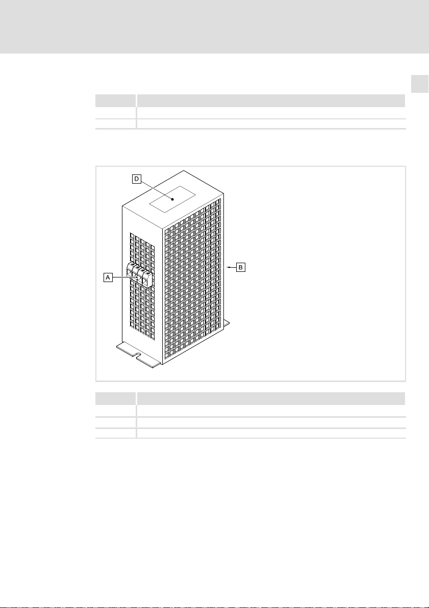
3.4 Übersicht
Position Beschreibung
0 Netzanschluss
1 Anschluss Grundgerät
3 Typenschild
EDKZN3B024 DE/EN/FR 3.0
l
EZN−051
11
Page 12
3
Produktbeschreibung
Identifikation
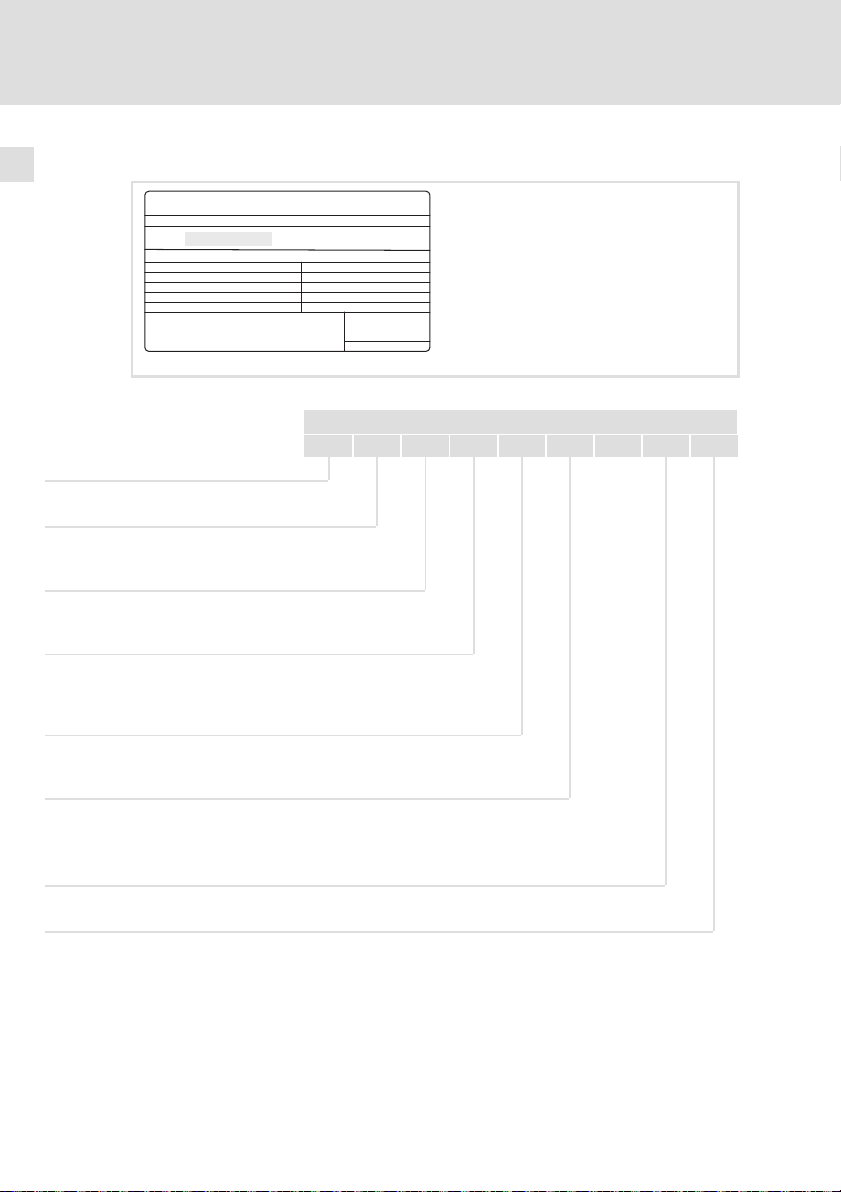
3.5 Identifikation
L
Type :
Abb. 3−1 Typenschild
Typenschlüssel
Produktreihe
Zubehör
Filtertyp
N = Netzfilter
Anzahl Phasen
3 = 3 Phasen
Grenzwertklasse nach EN 61800−3
A = Grenzwertklasse C2
B = Grenzwertklasse C1
Induktivität
z. B. 0055 = 0,55 mH
Hans-Lenze-Straße 1
D-31855 Aerzen
Made in Germany
8200vec080
E Z N 3 x xxxx H xxx xxxx
Bemessungsstrom
z. B. 060 = 60 A
Filter−Variante (opt.)
12
l
EDKZN3B024 DE/EN/FR 3.0
Page 13

Allgemeine Daten und Einsatzbedingungen
4 Technische Daten
4.1 Allgemeine Daten und Einsatzbedingungen
Konformität und Approbation
EAC
Angaben zu Netzen
Netzformen
Mit geerdetem Y−Punkt (TT−/TN−Netze) Betrieb uneingeschränkt erlaubt
Andere Netzformen Anweisungen über besondere Maßnahmen in der
TP TC 020/2011
(TR ZU 020/2011)
TP TC 004/2011
(TR ZU 004/2011)
Elektromagnetische
Verträglichkeit von
technischen Erzeugnissen
Über die Sicherheit
von Niederspannungsausrüstung
Dokumentation zum Grundgerät beachten!
Technische Daten
Eurasische Konformität
TR ZU: Technische Regulierung der Zollunion
Eurasische Konformität
TR ZU: Technische Regulierung der Zollunion
4
Schutz
Schutzart EN 60529
Isolationsfestigkeit EN 61800−5−1 Überspannungskategorie III
Ableitstrom EN 61800−5−1 > 3.5 mA Bestimmungen und
Umweltbedingungen
Temperatur
Lagerung
Transport −25 ... +70 °C
Betrieb −10 ... +55 °C (Temperatur im Schaltschrank)
Aufstellhöhe 0 ... 4000 m üNN
Verschmutzung EN 61800−5−1 Verschmutzungsgrad 2
Rüttelfestigkeit EN50178;
IEC61800−5−1;
Germanischer
Loyd, allgemeine
Bedingungen
IP 20 nicht im Anschlussbe-
Reduzierung ab 2000 m: Überspannungskategorie II
−25 ... +60 °C
Stromreduzierung von +40 ... +55 °C: 2.5 %/°C
1000 ... 4000 m üNN: Stromreduzierung 5 %/1000 m
Beschleunigungsfest bis 0.7 g
reich der Klemmen
Sicherheitshinweise
beachten!
EDKZN3B024 DE/EN/FR 3.0
l
13
Page 14

4
Technische Daten
Allgemeine Daten und Einsatzbedingungen
Montagebedingungen
Montageort im Schaltschrank
Montageposition oberhalb des Grundgerätes
Einbaulage senkrecht, Netzanschluss oben
Einbaufreiräume
oben und unten > 85 mm
seitlich > 20 mm
14
l
EDKZN3B024 DE/EN/FR 3.0
Page 15
Technische Daten
Bemessungsdaten
4
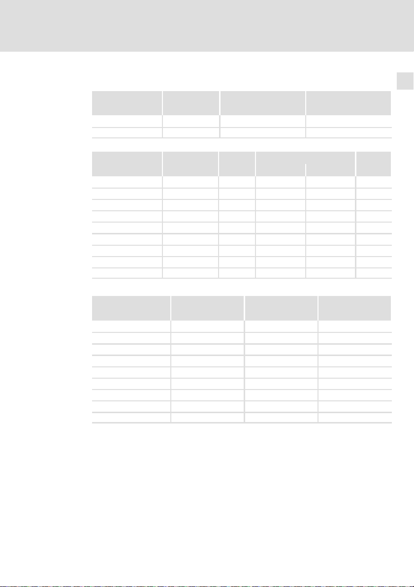
4.2 Bemessungsdaten
Netz Spannung Spannungsbereich Frequenzbereich
3/PE AC 400 320 − 0 % ... 440 + 0 % 45 − 0 % ... 65 + 0 %
3/PE AC 480 432 − 0 % ... 528 + 0 % 45 − 0 % ... 65 + 0 %
Typ
EZN3x2400H002 400/480 50/60 1.5 0.9 3
EZN3x1500H003 400/480 50/60 2.5 1.6 3
EZN3x0900H004 400/480 50/60 4.0 2.5 3
EZN3x0750H005 400/480 50/60 5.0 3.1 3
EZN3x0500H007 400/480 50/60 7.0 4.4 3
EZN3x0400H009 400/480 50/60 9.0 5.6 3
EZN3x0300H013 400/480 50/60 13.0 8.1 3
EZN3x0250H015 400/480 50/60 15.0 9.4 3
EZN3x0150H024 400/480 50/60 24.0 15.0 3
Temperatur im Schaltschrank
EZN3x2400H002 17 24 20
EZN3x1500H003 18 15 20
EZN3x0900H004 28 9.0 20
EZN3x0750H005 32 7.5 20
EZN3x0500H007 39 5.0 20
EZN3x0400H009 49 4.0 20
EZN3x0300H013 53 3.0 20
EZN3x0250H015 75 2.5 20
EZN3x0150H024 90 1.5 20
U
[V] U
LN
Spannung Frequenz Strom [A]
[V] [Hz] bis +40 °C bis +55 °C
Verlustleistung Induktivität Spannungsabfall
PV [W] L [mH] DU [V]
[V] f [Hz]
LN
Phasen-
zahl
EDKZN3B024 DE/EN/FR 3.0
l
15
Page 16

4
Technische Daten
Mechanische Daten
4.3 Mechanische Daten
16
Alle Maße in Millimeter.
l
EZN−052
EDKZN3B024 DE/EN/FR 3.0
Page 17

Technische Daten
Mechanische Daten
4
Typ
EZN3x2400H002
EZN3x1500H003
EZN3x0900H004
EZN3x0750H005
EZN3x0500H007
EZN3x0400H009
EZN3x0300H013
EZN3x0250H015
EZN3x0150H024
Maße
a a1 b b1 e m n
[mm] [kg]
120
150
180 150 97 165 −
260 230 135 245 92
230 125
78 135 −
Masse
2.5
3.1
3.2
5.2
5.6
5.9
11.5
12.4
12.5
EDKZN3B024 DE/EN/FR 3.0
l
17
Page 18

5
Mechanische Installation
Wichtige Hinweise
5 Mechanische Installation
5.1 Wichtige Hinweise
ƒ Der Montageort muss den in den Technischen Daten genannten
Einsatzbedingungen immer entsprechen (¶ 13). Ggf. zusätzliche
Maßnahmen ergreifen.
ƒ Die Montageplatte des Schaltschranks muss folgende Eigenschaften
aufweisen:
– elektrisch leitfähig
– lackfrei
ƒ Die mechanischen Verbindungen müssen immer gewährleistet sein.
ƒ Eine ungehinderte Luftzirkulation zum Abführen der Wärme muss
gewährleistet sein.
18
l
EDKZN3B024 DE/EN/FR 3.0
Page 19
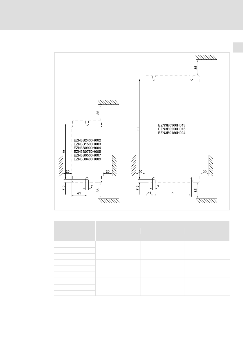
5.2 Bohrplan
Mechanische Installation
Bohrplan
5
Alle Maße in Millimeter.
Typ
EZN3x2400H002
EZN3x1500H003
EZN3x0900H004
EZN3x0750H005
EZN3x0500H007
EZN3x0400H009
EZN3x0300H013
EZN3x0250H015
EZN3x0150H024
EDKZN3B024 DE/EN/FR 3.0
Maße
e1 m n
[mm]
39 135 −
48.5 165 −
21.5 245 92
l
EZN−053
19
Page 20
5
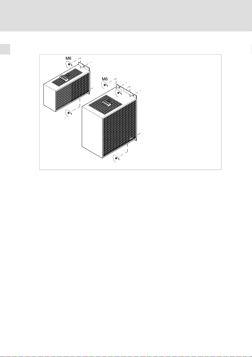
5.3 Montageschritte
Mechanische Installation
Montageschritte
So montieren Sie das Filter:
1. Montageplatte gemäß Bohrplan vorbereiten.
2. Filter je nach Ausführung mit 2 bzw. 4 Schrauben M6 und
Unterlegscheiben auf Montageplatte montieren.
EZN−054
20
l
EDKZN3B024 DE/EN/FR 3.0
Page 21

6 Elektrische Installation
6.1 Wichtige Hinweise
ƒ Die Installation muss
– den in den Technischen Daten genannten Einsatzbedingungen immer
entsprechen (¶ 13).
– nach EN 60204−1 ausgeführt werden.
ƒ Bei der Auswahl des Leitungstyps beachten:
– Die verwendeten Leitungen müssen den geforderten Approbationen
am Einsatzort entsprechen (z. B. VDE, UL usw.).
– Absicherung und Leitungsquerschnitte gemäß den Vorgaben in der
Dokumentation zum Grundgerät bemessen.
ƒ Beim Verlegen der PE−Leitung beachten:
– Der PE−Anschluss muss nach EN 61800−5−1 ausgeführt werden.
Elektrische Installation
Wichtige Hinweise
6
EDKZN3B024 DE/EN/FR 3.0
l
21
Page 22

6
Elektrische Installation
Anschlussplan
6.2 Anschlussplan
K1
L1
L2
L3
N
PE
F
0 Antriebsregler
EZN...
0
PE
L1
Load
L1'
PE
GN/YE
PE
Line
BK
L1
L2
L2'
L2
BK
L3
L3'
BK
L3
EZN003
22
l
EDKZN3B024 DE/EN/FR 3.0
Page 23

6.3 Anschlussdaten
Elektrische Installation
Anschlussdaten
6
EZN3x2400H002
EZN3x1500H003
EZN3x0900H004
EZN3x0750H005
EZN3x0500H007
EZN3x0400H009
EZN3x0300H013
EZN3x0250H015
EZN3x0150H024
6.4 Montageschritte
[mm2] [AWG] [mm]
0.2 ... 4
0.2 ... 6 0.25 ... 6 0.5 ... 4 24 ... 8 9
0.25 ... 4 0.5 ... 1.5 24 ... 10 8
[Nm]
[lb−in]
0.6 ... 0.8
5.3 ... 7.1
1.5 ... 1.8
13.2 ... 15.9
So verdrahten Sie das Filter:
1. Schaltschrank spannungsfrei schalten und gegen Wiedereinschalten
sichern.
2. Anschlussleitungen zum Grundgerät an Klemme "Load" anschließen 2.
– Montageanleitung des Grundgerätes beachten!
3. Netzleitungen an Klemme "Line" 0 anschließen.
– Anzugsmoment beachten!
EDKZN3B024 DE/EN/FR 3.0
l
EZN−055
23
Page 24

6
Elektrische Installation
Montageschritte
24
l
EDKZN3B024 DE/EN/FR 3.0
Page 25

Contents i
1 About this documentation 26. . . . . . . . . . . . . . . . . . . . . . . . . . . . . . . . . . . . . . . . . .
1.1 Validity information 26. . . . . . . . . . . . . . . . . . . . . . . . . . . . . . . . . . . . . . . .
1.2 Target group 26. . . . . . . . . . . . . . . . . . . . . . . . . . . . . . . . . . . . . . . . . . . . . .
1.3 Document history 26. . . . . . . . . . . . . . . . . . . . . . . . . . . . . . . . . . . . . . . . . .
1.4 Conventions used 27. . . . . . . . . . . . . . . . . . . . . . . . . . . . . . . . . . . . . . . . . . .
1.5 Notes used 28. . . . . . . . . . . . . . . . . . . . . . . . . . . . . . . . . . . . . . . . . . . . . . . .
2 Safety instructions 29. . . . . . . . . . . . . . . . . . . . . . . . . . . . . . . . . . . . . . . . . . . . . . . .
2.1 General safety information 29. . . . . . . . . . . . . . . . . . . . . . . . . . . . . . . . . . .
2.2 Residual hazards 30. . . . . . . . . . . . . . . . . . . . . . . . . . . . . . . . . . . . . . . . . . .
3 Product description 32. . . . . . . . . . . . . . . . . . . . . . . . . . . . . . . . . . . . . . . . . . . . . . .
3.1 Application as directed 32. . . . . . . . . . . . . . . . . . . . . . . . . . . . . . . . . . . . .
3.2 Filter − controller assignment 32. . . . . . . . . . . . . . . . . . . . . . . . . . . . . . . . .
3.3 Scope of supply 33. . . . . . . . . . . . . . . . . . . . . . . . . . . . . . . . . . . . . . . . . . . .
3.4 Overview 33. . . . . . . . . . . . . . . . . . . . . . . . . . . . . . . . . . . . . . . . . . . . . . . . . .
3.5 Identification 34. . . . . . . . . . . . . . . . . . . . . . . . . . . . . . . . . . . . . . . . . . . . . .
4 Technical data 35. . . . . . . . . . . . . . . . . . . . . . . . . . . . . . . . . . . . . . . . . . . . . . . . . . . .
4.1 General data and operating conditions 35. . . . . . . . . . . . . . . . . . . . . . . .
4.2 Rated data 37. . . . . . . . . . . . . . . . . . . . . . . . . . . . . . . . . . . . . . . . . . . . . . . .
4.3 Mechanical data 38. . . . . . . . . . . . . . . . . . . . . . . . . . . . . . . . . . . . . . . . . .
5 Mechanical installation 40. . . . . . . . . . . . . . . . . . . . . . . . . . . . . . . . . . . . . . . . . . . .
5.1 Important notes 40. . . . . . . . . . . . . . . . . . . . . . . . . . . . . . . . . . . . . . . . . . . .
5.2 Drilling pattern 41. . . . . . . . . . . . . . . . . . . . . . . . . . . . . . . . . . . . . . . . . . . .
5.3 Mounting steps 42. . . . . . . . . . . . . . . . . . . . . . . . . . . . . . . . . . . . . . . . . . . .
6 Electrical installation 43. . . . . . . . . . . . . . . . . . . . . . . . . . . . . . . . . . . . . . . . . . . . . .
6.1 Important notes 43. . . . . . . . . . . . . . . . . . . . . . . . . . . . . . . . . . . . . . . . . . . .
6.2 Connection plan 44. . . . . . . . . . . . . . . . . . . . . . . . . . . . . . . . . . . . . . . . . . . .
6.3 Connection data 45. . . . . . . . . . . . . . . . . . . . . . . . . . . . . . . . . . . . . . . . . . . .
6.4 Mounting steps 45. . . . . . . . . . . . . . . . . . . . . . . . . . . . . . . . . . . . . . . . . . . .
EDKZN3B024 DE/EN/FR 3.0
l
25
Page 26

1
About this documentation
Validity information
1 About this documentation
0Fig. 0Tab. 0
1.1 Validity information
These instructions are valid for
ƒ Mains filter EZN3B2400H002
ƒ Mains filter EZN3B1500H003
ƒ Mains filter EZN3B0900H004
ƒ Mains filter EZN3B0750H005
ƒ Mains filter EZN3B0500H007
ƒ Mains filter EZN3B0400H009
ƒ Mains filter EZN3B0300H013
ƒ Mains filter EZN3B0250H015
ƒ Mains filter EZN3B0150H024
1.2 Target group
This documentation is directed at qualified skilled personnel according to
IEC 60364.
Qualified skilled personnel are persons who have the required qualifications to
carry out all activities involved in installing, mounting, commissioning, and
operating the product.
I Tip!
Information and tools concerning the Lenze products can be found
in the download area under
www.lenze.com
1.3 Document history
Material number Version Description
.Oe$ 3.0 09/2014 TD29 EAC Conformity
13336826 2.1 11/2011 TD00 Revision
13336826 2.0 04/2010 TD29 New edition due to reorganisation of the
13216453 1.0 10/2007 TD29 First edition
26
l
General corrections
company, layout adaption and revision
EDKZN3B024 DE/EN/FR 3.0
Page 27

1.4 Conventions used
Type of information Identification Examples/notes
Spelling of numbers
Decimal separator Point In general, the decimal point is used.
Warnings
UL warnings
UR warnings
Text
Program name » « PC software
Icons
Page reference ^ Reference to another page with
About this documentation
Conventions used
For instance: 1234.56
J
O
Given in English and French
For example: »Engineer«, »Global
Drive Control« (GDC)
additional information
For instance: ^ 16 = see page 16
1
EDKZN3B024 DE/EN/FR 3.0
l
27
Page 28

1
About this documentation
Notes used
1.5 Notes used
The following pictographs and signal words are used in this documentation to
indicate dangers and important information:
Safety instructions
Structure of safety instructions:
} Danger!
Pictograph and signal word Meaning
{ Danger!
} Danger!
( Stop!
Application notes
(characterises the type and severity of danger)
Note
(describes the danger and gives information about how to prevent
dangerous situations)
Danger of personal injury through dangerous electrical
voltage.
Reference to an imminent danger that may result in
death or serious personal injury if the corresponding
measures are not taken.
Danger of personal injury through a general source of
danger.
Reference to an imminent danger that may result in
death or serious personal injury if the corresponding
measures are not taken.
Danger of property damage.
Reference to a possible danger that may result in
property damage if the corresponding measures are not
taken.
28
Pictograph and signal word Meaning
) Note!
I Tip!
,
Important note to ensure troublefree operation
Useful tip for simple handling
Reference to another documentation
l
EDKZN3B024 DE/EN/FR 3.0
Page 29

2 Safety instructions
2.1 General safety information
} Danger!
Disregarding the following basic safety measures may lead to
severe personal injury and damage to material assets!
ƒ Lenze drive and automation components ...
... must only be used for the intended purpose.
... must never be operated if damaged.
... must never be subjected to technical modifications.
... must never be operated unless completely assembled.
... must never be operated without the covers/guards.
... can − depending on their degree of protection − have live, movable or
rotating parts during or after operation. Surfaces can be hot.
ƒ All specifications of the corresponding enclosed documentation must be
observed.
This is vital for a safe and trouble−free operation and for achieving the
specified product features.
The procedural notes and circuit details provided in this document are
proposals which the user must check for suitability for his application. The
manufacturer does not accept any liability for the suitability of the specified
procedures and circuit proposals.
ƒ Only qualified skilled personnel are permitted to work with or on Lenze
drive and automation components.
According to IEC 60364 or CENELEC HD 384, these are persons ...
... who are familiar with the installation, assembly, commissioning and
operation of the product,
... possess the appropriate qualifications for their work,
... and are acquainted with and can apply all the accident prevent
regulations, directives and laws applicable at the place of use.
Safety instructions
General safety information
2
EDKZN3B024 DE/EN/FR 3.0
l
29
Page 30

2
Safety instructions
Residual hazards
2.2 Residual hazards
{ Danger!
Dangerous electrical voltage
All power terminals remain live for up to three minutes after mains
disconnection.
Possible consequences:
ƒ Death or severe injuries when touching the power terminals.
Protective measures:
ƒ Switch off the power supply and wait for at least three minutes
before working on the power terminals.
ƒ Make sure that all power terminals are deenergised.
{ Danger!
Hazardous electrical voltage
The leakage current to earth (PE) is > 3.5 mA AC or > 10 mA DC.
Possible consequences:
ƒ Death or severe injuries when touching the device in the event of
an error.
Protective measures:
Implement the measures required in EN 61800−5−1. Especially:
ƒ Fixed installation
– Implement PE connection in compliance with standards.
– Connect PE conductor twice or PE conductor cross−section
ƒ Connection with a connector for industrial applications according
to IEC 60309 (CEE):
– PE conductor cross−section ³ 2.5 mm2 as part of a multi−core
– Provide for suitable strain relief.
³ 10 mm
supply cable.
2
.
30
l
EDKZN3B024 DE/EN/FR 3.0
Page 31

Safety instructions
Residual hazards
( Stop!
No device protection if the mains voltage is too high
The mains input is not internally fused.
Possible consequences:
ƒ Destruction of the device if the mains voltage is too high.
Protective measures:
ƒ Observe the maximally permissible mains voltage.
ƒ Fuse the device correctly on the supply side against mains
fluctuations and voltage peaks.
2
EDKZN3B024 DE/EN/FR 3.0
l
31
Page 32

3
Product description
Application as directed
3 Product description
3.1 Application as directed
Mains filters and RFI filters
ƒ are units which can be used with Lenze controllers.
ƒ may only be connected to Lenze controllers if the requirements of the
documentation for the controller are met.
ƒ may only be operated under the operating conditions specified in these
operating instructions.
ƒ are components
– for installation in a machine.
– used for assembly with other components to form a machine.
ƒ are electrical equipment for the installation into control cabinets or
similar closed electrical operating areas..
ƒ comply with the requirements of the LowVoltage Directive.
ƒ are not machines for the purpose of the EC Machinery Directive.
ƒ are no household appliances but are intended exclusively as components
for further commercial use.
Drive systems with filters
ƒ The user is responsible for the compliance of his machine application with
the EC Directives.
Any other use shall be deemed inappropriate!
3.2 Filter − controller assignment
) Note!
The filter «controller assignment can be obtained from the project
planning instructions in the manual for the standard device.
32
l
EDKZN3B024 DE/EN/FR 3.0
Page 33

Product description
Scope of supply
3
3.3 Scope of supply
Quantity Description
1 Filter
1 Mounting Instructions
3.4 Overview
Position Description
0 Mains connection
1 Connection of the standard device
3 Nameplate
EDKZN3B024 DE/EN/FR 3.0
l
EZN−051
33
Page 34

3
Product description
Identification
3.5 Identification
L
Type :
Fig. 3−1 Nameplate
Type code
Product series
Accessories
Type of filter
N = mains filter
Number of phases
3 = 3 phases
Limit class according to EN 61800−3
A = limit class C2
B = limit class C1
Inductance
e.g. 0055 = 0.55 mH
Hans-Lenze-Straße 1
D-31855 Aerzen
Made in Germany
8200vec080
E Z N 3 x xxxx H xxx xxxx
Rated current
e.g. 060 = 60 A
Filter variant (opt.)
34
l
EDKZN3B024 DE/EN/FR 3.0
Page 35

General data and operating conditions
4 Technical data
4.1 General data and operating conditions
Conformity and approval
EAC
Mains data
Mains types
With grounded neutral (TT/TN systems)
Other mains types Observe instructions for special measures in the
TP TC 020/2011
(TR CU 020/2011)
TP TC 004/2011
(TR CU 004/2011)
Electromagnetic
compatibility of
technical means
On safety of low
voltage equipment
Operation permitted without restrictions
documentation for the basic device!
Technical data
Eurasian Conformity
TR CU: Technical Regulation
of Customs Union
Eurasian Conformity
TR CU: Technical Regulation
of Customs Union
4
Protection
Degree of protection EN 60529 IP 20 Not in the wire range
Insulation resistance EN 61800−5−1 Overvoltage category III
Leakage current EN 61800−5−1 > 3.5 mA Observe regulations
Ambient conditions
Temperature
Storage
Transport −25 ... +70 °C
Operation −10 ... +55 °C (Temperature in the control cabinet)
Site altitude 0 ... 4000 m amsl
Pollution EN 61800−5−1 Pollution degree 2
Vibration resistance EN 50178; IEC
61800−5−1;
Germanischer
Lloyd, general
conditions
> 2000 m: Overvoltage category II
−25 ... +60 °C
Current derating from +40 ... +55 °C: 2.5 %/°C
1000 ... 4000 m amsl: Current derating by
5 %/1000 m
Acceleration−resistant up to 0.7 g
of the terminals
and safety
instructions!
EDKZN3B024 DE/EN/FR 3.0
l
35
Page 36

4
Technical data
General data and operating conditions
Mounting conditions
Mounting location In the control cabinet
Mounting position Above the standard device
Mounting position Vertical, mains connection on top
Free spaces
at the top and at the
bottom
to the sides > 20 mm
> 85 mm
36
l
EDKZN3B024 DE/EN/FR 3.0
Page 37

Technical data
Rated data
4
4.2 Rated data
Mains Voltage Voltage range Frequency range
3/PE AC 400 320 − 0 % ... 440 + 0 % 45 − 0 % ... 65 + 0 %
3/PE AC 480 432 − 0 % ... 528 + 0 % 45 − 0 % ... 65 + 0 %
Type
EZN3x2400H002 400/480 50/60 1.5 0.9 3
EZN3x1500H003 400/480 50/60 2.5 1.6 3
EZN3x0900H004 400/480 50/60 4.0 2.5 3
EZN3x0750H005 400/480 50/60 5.0 3.1 3
EZN3x0500H007 400/480 50/60 7.0 4.4 3
EZN3x0400H009 400/480 50/60 9.0 5.6 3
EZN3x0300H013 400/480 50/60 13.0 8.1 3
EZN3x0250H015 400/480 50/60 15.0 9.4 3
EZN3x0150H024 400/480 50/60 24.0 15.0 3
Temperature in the control cabinet
EZN3x2400H002 17 24 20
EZN3x1500H003 18 15 20
EZN3x0900H004 28 9.0 20
EZN3x0750H005 32 7.5 20
EZN3x0500H007 39 5.0 20
EZN3x0400H009 49 4.0 20
EZN3x0300H013 53 3.0 20
EZN3x0250H015 75 2.5 20
EZN3x0150H024 90 1.5 20
U
[V] U
Lrated
Voltage Frequency Current [A]
[V] [Hz] up to +40 °C up to +55 °C
Power loss Inductance Voltage drop
P
[W] L [mH] DU [V]
loss
[V] f [Hz]
Lrated
Number
of phases
EDKZN3B024 DE/EN/FR 3.0
l
37
Page 38

4
Technical data
Mechanical data
4.3 Mechanical data
38
All dimensions in millimetres.
l
EZN−052
EDKZN3B024 DE/EN/FR 3.0
Page 39

Technical data
Mechanical data
4
Type
EZN3x2400H002
EZN3x1500H003
EZN3x0900H004
EZN3x0750H005
EZN3x0500H007
EZN3x0400H009
EZN3x0300H013
EZN3x0250H015
EZN3x0150H024
Dimensions
a a1 b b1 e m n
[mm] [kg]
120
150
180 150 97 165 −
260 230 135 245 92
230 125
78 135 −
Mass
2.5
3.1
3.2
5.2
5.6
5.9
11.5
12.4
12.5
EDKZN3B024 DE/EN/FR 3.0
l
39
Page 40

5
Mechanical installation
Important notes
5 Mechanical installation
5.1 Important notes
ƒ The mounting location must always comply with the operating conditions
specified in the technical data (¶ 35). Take additional measures if
necessary.
ƒ The mounting plate of the control cabinet must have the following
properties:
– electrically conductive
– free of lacquer
ƒ The mechanical connections must always be ensured.
ƒ A free air circulation must be ensured for dissipating the heat.
40
l
EDKZN3B024 DE/EN/FR 3.0
Page 41

5.2 Drilling pattern
Mechanical installation
Drilling pattern
5
All dimensions in millimetres.
Type
EZN3x2400H002
EZN3x1500H003
EZN3x0900H004
EZN3x0750H005
EZN3x0500H007
EZN3x0400H009
EZN3x0300H013
EZN3x0250H015
EZN3x0150H024
EDKZN3B024 DE/EN/FR 3.0
Dimensions
e1 m n
[mm]
39 135 −
48.5 165 −
21.5 245 92
l
EZN−053
41
Page 42

5
5.3 Mounting steps
Mechanical installation
Mounting steps
How to mount the filter:
1. Prepare the mounting plate as shown in the drilling pattern.
2. Mount the filter to the mounting plate using 2 or 4 M6 screws and
washers, respectively (design−dependent).
EZN−054
42
l
EDKZN3B024 DE/EN/FR 3.0
Page 43

6 Electrical installation
6.1 Important notes
ƒ Installation must
– always be in accordance with the operating conditions specified in the
Technical data (¶ 35).
– be carried out to EN 60204−1.
ƒ Please observe the following when selecting the cable type:
– The cables used must comply with the approvals required for the
application (e. g. VDE, UL etc.).
– Fuses and cable cross−sections must be dimensioned in accordance with
the specifications in the documentation for the basic device.
ƒ Please observe the following when laying the PE cable:
– The PE connection must comply with EN 61800−5−1.
Electrical installation
Important notes
6
EDKZN3B024 DE/EN/FR 3.0
l
43
Page 44

6
Electrical installation
Connection plan
6.2 Connection plan
K1
L1
L2
L3
N
PE
F
0 Controller
EZN...
0
PE
L1
Load
L1'
PE
GN/YE
PE
Line
BK
L1
L2
L2'
L2
BK
L3
L3'
BK
L3
EZN003
44
l
EDKZN3B024 DE/EN/FR 3.0
Page 45

6.3 Connection data
Electrical installation
Connection data
6
EZN3x2400H002
EZN3x1500H003
EZN3x0900H004
EZN3x0750H005
EZN3x0500H007
EZN3x0400H009
EZN3x0300H013
EZN3x0250H015
EZN3x0150H024
6.4 Mounting steps
[mm2] [AWG] [mm]
0.2 ... 4
0.2 ... 6 0.25 ... 6 0.5 ... 4 24 ... 8 9
0.25 ... 4 0.5 ... 1.5 24 ... 10 8
[Nm]
[lb−in]
0.6 ... 0.8
5.3 ... 7.1
1.5 ... 1.8
13.2 ... 15.9
How to wire the filter:
1. Deenergise the control cabinet and fuse it against re−energisation.
2. Connect the connection cables of the standard device to terminal "Load"
2.
– Observe the documentation of the standard device!
3. Connect the mains cables to terminal "Line" 0.
– Observe tightening torque!
EDKZN3B024 DE/EN/FR 3.0
l
EZN−055
45
Page 46

6
Electrical installation
Mounting steps
46
l
EDKZN3B024 DE/EN/FR 3.0
Page 47

Sommaire i
1 Présentation du document 48. . . . . . . . . . . . . . . . . . . . . . . . . . . . . . . . . . . . . . . . .
1.1 Validité 48. . . . . . . . . . . . . . . . . . . . . . . . . . . . . . . . . . . . . . . . . . . . . . . . . . .
1.2 Public visé 48. . . . . . . . . . . . . . . . . . . . . . . . . . . . . . . . . . . . . . . . . . . . . . . . .
1.3 Historique du document 48. . . . . . . . . . . . . . . . . . . . . . . . . . . . . . . . . . . . .
1.4 Conventions utilisées 49. . . . . . . . . . . . . . . . . . . . . . . . . . . . . . . . . . . . . . .
1.5 Consignes utilisées 50. . . . . . . . . . . . . . . . . . . . . . . . . . . . . . . . . . . . . . . . .
2 Consignes de sécurité 51. . . . . . . . . . . . . . . . . . . . . . . . . . . . . . . . . . . . . . . . . . . . . .
2.1 Consignes générales de sécurité 51. . . . . . . . . . . . . . . . . . . . . . . . . . . . . . .
2.2 Dangers résiduels 52. . . . . . . . . . . . . . . . . . . . . . . . . . . . . . . . . . . . . . . . . .
3 Description du produit 54. . . . . . . . . . . . . . . . . . . . . . . . . . . . . . . . . . . . . . . . . . . . .
3.1 Utilisation conforme à la fonction 54. . . . . . . . . . . . . . . . . . . . . . . . . . . .
3.2 Combinaisons filtre ˘ appareil de base 54. . . . . . . . . . . . . . . . . . . . . . . . .
3.3 Équipement livré> 55. . . . . . . . . . . . . . . . . . . . . . . . . . . . . . . . . . . . . . . . . .
3.4 Présentation générale 55. . . . . . . . . . . . . . . . . . . . . . . . . . . . . . . . . . . . . . .
3.5 Identification 56. . . . . . . . . . . . . . . . . . . . . . . . . . . . . . . . . . . . . . . . . . . . . .
4 Spécifications techniques 57. . . . . . . . . . . . . . . . . . . . . . . . . . . . . . . . . . . . . . . . . .
4.1 Caractéristiques générales et conditions d’utilisation 57. . . . . . . . . . . .
4.2 Caractéristiques assignées 59. . . . . . . . . . . . . . . . . . . . . . . . . . . . . . . . . . .
4.3 Caractéristiques mécaniques 60. . . . . . . . . . . . . . . . . . . . . . . . . . . . . . . .
5 Installation mécanique 62. . . . . . . . . . . . . . . . . . . . . . . . . . . . . . . . . . . . . . . . . . . .
5.1 Remarques importantes 62. . . . . . . . . . . . . . . . . . . . . . . . . . . . . . . . . . . . .
5.2 Modèle de perçage 63. . . . . . . . . . . . . . . . . . . . . . . . . . . . . . . . . . . . . . . . . .
5.3 Opérations de montage 64. . . . . . . . . . . . . . . . . . . . . . . . . . . . . . . . . . . . . .
6 Installation électrique 65. . . . . . . . . . . . . . . . . . . . . . . . . . . . . . . . . . . . . . . . . . . . .
6.1 Remarques importantes 65. . . . . . . . . . . . . . . . . . . . . . . . . . . . . . . . . . . . .
6.2 Schéma de câblage 66. . . . . . . . . . . . . . . . . . . . . . . . . . . . . . . . . . . . . . . . .
6.3 Données de raccordement 67. . . . . . . . . . . . . . . . . . . . . . . . . . . . . . . . . . .
6.4 Opérations de montage 68. . . . . . . . . . . . . . . . . . . . . . . . . . . . . . . . . . . . . .
EDKZN3B024 DE/EN/FR 3.0
l
47
Page 48

1
Présentation du document
Validité
1 Présentation du document
0Fig. 0Tab. 0
1.1 Validité
Le présent document s’applique au produits suivants :
ƒ Filtre réseau EZN3B2400H002
ƒ Filtre réseau EZN3B1500H003
ƒ Filtre réseau EZN3B0900H004
ƒ Filtre réseau EZN3B0750H005
ƒ Filtre réseau EZN3B0500H007
ƒ Filtre réseau EZN3B0400H009
ƒ Filtre réseau EZN3B0300H013
ƒ Filtre réseau EZN3B0250H015
ƒ Filtre réseau EZN3B0150H024
1.2 Public visé
Cette documentation s’adresse à un personnel qualifié et habilité
conformément à la norme CEI 60364.
On entend par "personnel qualifié et habilité" des personnes compétentes en
matière d’installation, de montage, de mise en service et de fonctionnement du
produit et possédant les qualifications correspondant à leurs activités.
I Conseil !
Toutes les informations relatives aux produits Lenze peuvent être
téléchargées sur notre site à l’adresse suivante :
www.Lenze.com
1.3 Historique du document
Numéro de matériel Version Description
.Oe$ 3.0 09/2014 TD29 Conformité EAC
13336826 2.1 11/2011 TD00 Révision
13336826 2.0 04/2010 TD29 Nouvelle édition en raison de la nouvelle
13216453 1.0 10/2007 TD29 Première édition
48
l
Corrections générales
organisation de l´entreprise, adaption de la
mise en page e révision
EDKZN3B024 DE/EN/FR 3.0
Page 49

1.4 Conventions utilisées
Type d’information Aperçu Exemples/remarques
Représentation des chiffres
Séparateur décimal Point Le point décimal est généralement
Consignes préventives
Consignes préventives UL
Consignes préventives UR
Mise en évidence de textes spéciaux
Nom de programme » « Logiciel pour PC
Pictogrammes
Renvoi à la page ^ Renvoi à une autre page contenant
Présentation du document
Conventions utilisées
utilisé.
Exemple : 1234.56
J
O
En anglais et en français
Exemple : »Engineer«, »Global Drive
Control« (GDC)
des informations complémentaires
Exemple : ^ 16 = voir page 16
1
EDKZN3B024 DE/EN/FR 3.0
l
49
Page 50

1
Présentation du document
Consignes utilisées
1.5 Consignes utilisées
Pour indiquer des risques et des informations importantes, la présente
documentation utilise les mots et pictogrammes suivants :
Consignes de sécurité
Présentation des consignes de sécurité
} Danger !
(Le pictogramme indique le type de risque.)
Explication
(L’explication décrit le risque et les moyens de l’éviter.)
Pictogramme et mot associé Explication
{ Danger !
} Danger !
( Stop !
Consignes d’utilisation
Situation dangereuse pour les personnes en raison
d’une tension électrique élevée
Indication d’un danger imminent qui peut avoir pour
conséquences des blessures mortelles ou très graves en
cas de non−respect des consignes de sécurité
correspondantes
Situation dangereuse pour les personnes en raison d’un
danger d’ordre général
Indication d’un danger imminent qui peut avoir pour
conséquences des blessures mortelles ou très graves en
cas de non−respect des consignes de sécurité
correspondantes
Risques de dégâts matériels
Indication d’un risque potentiel qui peut avoir pour
conséquences des dégâts matériels en cas de
non−respect des consignes de sécurité correspondantes
50
Pictogramme et mot associé Explication
) Remarque
importante !
I Conseil !
,
Remarque importante pour assurer un fonctionnement
correct
Conseil utile pour faciliter la mise en uvre
Renvoi à une autre documentation
l
EDKZN3B024 DE/EN/FR 3.0
Page 51

2 Consignes de sécurité
2.1 Consignes générales de sécurité
} Danger !
Le non−respect des consignes fondamentales de sécurité suivantes
peut entraîner des blessures et des dommages matériels graves.
ƒ Les composants d’entraînement et d’automatisation Lenze ...
... doivent exclusivement être utilisés conformément à leur fonction.
... ne doivent jamais être mis en service si des dommages sont décelés.
... ne doivent jamais être modifiés d’un point de vue technique.
... ne doivent jamais être mis en service s’ils ne sont pas montés
intégralement.
... ne doivent jamais être mis en service sans le capot obligatoire.
... peuvent − selon l’indice de protection − contenir des pièces sous tension, en
mouvement ou en rotation. Les surfaces peuvent être brûlantes.
ƒ Respecter les consignes et les indications contenues dans la
documentation concernée.
Il s’agit de la condition préalable pour garantir un fonctionnement sûr et
fiable et pour obtenir les caractéristiques du produit indiquées.
Les procédures à suivre et les plans de raccordement fournis constituent des
recommandations dont l’adéquation avec l’application concernée doit être
vérifiée. Lenze n’assumera aucune responsabilité pour les dommages liés à
un problème d’adéquation des procédures et plans de raccordements
indiqués.
ƒ Les travaux réalisés avec et au niveau des composants d’entraînement et
d’automatisation Lenze ne doivent être exécutés que par un personnel
qualifié et habilité.
Selon les normes CEI 60364 ou CENELEC HD 384, ces personnes doivent ...
... connaître parfaitement l’installation, le montage, la mise en service et le
fonctionnement du produit.
... posséder les qualifications appropriées pour l’exercice de leur activité.
... connaître toutes les prescriptions pour la prévention d’accidents,
directives et lois applicables sur le lieu d’utilisation et être en mesure de les
appliquer.
Consignes de sécurité
Consignes générales de sécurité
2
EDKZN3B024 DE/EN/FR 3.0
l
51
Page 52

2
Consignes de sécurité
Dangers résiduels
2.2 Dangers résiduels
{ Danger !
Tension électrique dangereuse
Les raccordements de puissance sont encore sous tension jusqu’à 3
minutes après la coupure réseau.
Risques encourus :
ƒ Mort ou blessures graves en cas de contact accidentel avec les
raccordements de puissance.
Mesures de protection :
ƒ Avant toute intervention au niveau des raccordements de
puissance, couper l’alimentation et attendre au moins 3 minutes.
ƒ S’assurer que tous les raccordements de puissance sont hors
tension.
{ Danger !
Tension électrique dangereuse
Le courant de fuite vers la terre (PE) est > 3.5 mA CA ou > 10 mA CC.
Risques encourus :
ƒ Mort ou blessures graves en cas de contact accidentel avec
l’appareil en défaut
Mesures de protection :
Mettre en œuvre les mesures prescrites par la norme EN 61800−5−1,
notamment :
ƒ Installation fixe
– Prévoir un raccordement PE conformément à la norme.
– Prévoir un double raccordement du câble PE ou une section de
câble PE ³ 10 mm
ƒ Raccordement à l’aide d’un connecteur adapté aux applications
industrielles selon la norme CEI 60309 (CEE)
– La section de câble PE ³ 2.5 mm2 représente une partie du
câble d’alimentation multiconducteur.
– Utiliser un dispositif de décharge de traction adapté.
2
.
52
l
EDKZN3B024 DE/EN/FR 3.0
Page 53

Consignes de sécurité
Dangers résiduels
( Stop !
Appareil non protégé contre une tension réseau trop élevée
Il n’y a pas de protection intégrée de l’entrée réseau.
Risques encourus :
ƒ Dommages irréversibles de l’appareil en cas de tension réseau
trop élevée
Mesures de protection :
ƒ Respecter la tension réseau maximale admissible.
ƒ Protéger l’appareil de manière adaptée côté réseau contre les
fluctuations du réseau et les pointes de tension.
2
EDKZN3B024 DE/EN/FR 3.0
l
53
Page 54

3
Description du produit
Utilisation conforme à la fonction
3 Description du produit
3.1 Utilisation conforme à la fonction
Les filtres réseau et les filtres antiparasites
ƒ sont des unités complémentaires pour les variateurs de vitesse Lenze.
ƒ ne doivent être raccordés aux variateurs de vitesse Lenze que si les
prescriptions de la documentation sur le variateur de vitesse sont
remplies.
ƒ ne doivent fonctionner que dans les conditions d’utilisation prescites dans
le présent document.
ƒ sont des appareils
– destinés à être intégrés dans une machine.
– destinés à être assemblés avec d’autres composants pour former une
machine.
ƒ sont des équipements électriques destinés à être montés dans les
armoires électriques ou d’autres locaux de service clos.
ƒ remplissent les exigences de sécurité de la directive CE "Basse tension".
ƒ ne sont pas des machines au sens de la directive CE relative aux machines.
ƒ ne sont pas des appareils ménagers, mais des composants destinés
exclusivement à une utilisation professionnelle.
Systèmes d’entraînement avec filtres
ƒ La responsabilité de la conformité aux directives CE incombe à
l’exploitant de la machine.
Toute autre utilisation est contre−indiquée !
3.2 Combinaisons filtre ˘ appareil de base
) Remarque importante !
Pour la combinaison filtre «variateur, se reporter aux consignes
d’élaboration du projet dans le manuel de l’appareil de base.
54
l
EDKZN3B024 DE/EN/FR 3.0
Page 55

Description du produit
Équipement livré
3
3.3 Équipement livré>
Nombre Description
1 Filtre
1 Instructions de montage
3.4 Présentation générale
Position Description
0 Alimentation réseau
1 Raccordement de l’appareil de base
3 Plaque signalétique
EDKZN3B024 DE/EN/FR 3.0
l
EZN−051
55
Page 56

3
Description du produit
Identification
3.5 Identification
L
Type :
Fig.3−1 Plaque signalétique
Codification des types
Série d’appareils
Accessoires
Type de filtre
N = filtre réseau
Hans-Lenze-Straße 1
D-31855 Aerzen
Nombre de phases
3 = 3 phases
Classe d’antiparasitage suivant EN 61800−3
A = classe C2
B = classe C1
Inductance
Ex. : 0055 = 0,55 mH
Made in Germany
8200vec080
E Z N 3 x xxxx H xxx xxxx
Courant nominal
Ex. : 060 = 60 A
Variante de filtre (opt.)
56
l
EDKZN3B024 DE/EN/FR 3.0
Page 57

Spécifications techniques
Caractéristiques générales et conditions d’utilisation
4 Spécifications techniques
4.1 Caractéristiques générales et conditions d’utilisation
Conformité et homologation
EAC
Informations sur les réseaux
Configurations réseau
Avec point Y à la terre (réseaux TT/TN)
Autres configurations réseau Respecter les indications concernant les mesures
Protection
Indice de protection EN 60529 IP 20 Pas dans la zone de
Résistance d’isolement EN 61800−5−1 Catégorie de surtension III
Courant de fuite EN 61800−5−1 > 3.5 mA Tenir compte des
TP TC 020/2011
(RT UD 020/2011)
TP TC 004/2011
(RT UD 004/2011)
Compatibilité
électromagnétique des
équipements
Sécurité des
équipements à basse
tension
Utilisation sans restriction
particulières dans la documentation de l’appareil de
base !
Réduction à partir de 2000 m : catégorie de
surtension II
Conformité eurasienne
RT UD : Règlement
technique de l’Union
Douanière
Conformité eurasienne
RT UD : Règlement
technique de l’Union
Douanière
raccordement des
bornes
prescriptions et des
consignes de sécurité !
4
EDKZN3B024 DE/EN/FR 3.0
l
57
Page 58

4
Spécifications techniques
Caractéristiques générales et conditions d’utilisation
Conditions climatiques
Température
Stockage
Transport −25 ... +70 °C
Fonctionnement −10 ... +55 °C (température dans l’armoire électrique)
Altitude
d’implantation
Pollution ambiante
admissible
Résistance aux chocs EN50178 ;
Conditions de montage
Lieu de montage Armoire électrique
Position de montage Au−dessus de l’appareil de base
Position de montage Verticale, raccordement réseau vers le haut
Espaces de montage
En haut et en bas > 85 mm
Sur le côté > 20 mm
EN 61800−5−1 Degré de pollution 2
IEC61800−5−1 ;
Germanischer
Loyd, Conditions
générales
−25 ... +60 °C
Réduction de courant dans la plage +40 ... +55 °C :
2,5 %/°C
0 ... 4000 m au−dessus du niveau de la mer
1000 ... 4000 m au−dessus du niveau de la mer :
réduction de courant de 5 %/1000 m
Résistance à l’accélération jusqu’à 0,7 g
58
l
EDKZN3B024 DE/EN/FR 3.0
Page 59

Spécifications techniques
Caractéristiques assignées
4
4.2 Caractéristiques assignées
Réseau Tension Plage de tension Plage de fréquence
U
LN
3/PE CA 400 320 − 0 % ... 440 + 0 % 45 − 0 % ... 65 + 0 %
3/PE CA 480 432 − 0 % ... 528 + 0 % 45 − 0 % ... 65 + 0 %
Type
EZN3x2400H002 400/480 50/60 1.5 0.9 3
EZN3x1500H003 400/480 50/60 2.5 1.6 3
EZN3x0900H004 400/480 50/60 4.0 2.5 3
EZN3x0750H005 400/480 50/60 5.0 3.1 3
EZN3x0500H007 400/480 50/60 7.0 4.4 3
EZN3x0400H009 400/480 50/60 9.0 5.6 3
EZN3x0300H013 400/480 50/60 13.0 8.1 3
EZN3x0250H015 400/480 50/60 15.0 9.4 3
EZN3x0150H024 400/480 50/60 24.0 15.0 3
Température dans l’armoire électrique
EZN3x2400H002 17 24 20
EZN3x1500H003 18 15 20
EZN3x0900H004 28 9.0 20
EZN3x0750H005 32 7.5 20
EZN3x0500H007 39 5.0 20
EZN3x0400H009 49 4.0 20
EZN3x0300H013 53 3.0 20
EZN3x0250H015 75 2.5 20
EZN3x0150H024 90 1.5 20
Tension Fréquence Courant [A]
[V] [Hz] Jusqu’à +40 °CJusqu’à +55 °C
Puissance dissipée Inductance Chute de tension
[V] U
PV [W] L [mH] DU [V]
[V] f [Hz]
LN
Nombre
de phases
EDKZN3B024 DE/EN/FR 3.0
l
59
Page 60

4
Spécifications techniques
Caractéristiques mécaniques
4.3 Caractéristiques mécaniques
60
Cotes en [mm]
l
EZN−052
EDKZN3B024 DE/EN/FR 3.0
Page 61

Spécifications techniques
Caractéristiques mécaniques
4
Type
EZN3x2400H002
EZN3x1500H003
EZN3x0900H004
EZN3x0750H005
EZN3x0500H007
EZN3x0400H009
EZN3x0300H013
EZN3x0250H015
EZN3x0150H024
Cotes
a a1 b b1 e m n
[mm] [kg]
120
150
180 150 97 165 −
260 230 135 245 92
230 125
78 135 −
Poids
2.5
3.1
3.2
5.2
5.6
5.9
11.5
12.4
12.5
EDKZN3B024 DE/EN/FR 3.0
l
61
Page 62

5
Installation mécanique
Remarques importantes
5 Installation mécanique
5.1 Remarques importantes
ƒ L’emplacement de montage doit impérativement remplir les conditions
d’utilisation décrites dans les spécifications techniques.(¶ 57). Si
nécessaire, prendre des mesures complémentaires.
ƒ La plaque de montage de l’armoire électrique doit présenter les
caractéristiques suivantes :
– Conductivité électrique
– Pas de vernis
ƒ Les liaisons mécaniques doivent toujours être assurées.
ƒ Veiller à assurer une bonne circulation de l’air en vue de la dissipation de
la chaleur.
62
l
EDKZN3B024 DE/EN/FR 3.0
Page 63

5.2 Modèle de perçage
Installation mécanique
Modèle de perçage
5
Cotes en [mm]
Type
EZN3x2400H002
EZN3x1500H003
EZN3x0900H004
EZN3x0750H005
EZN3x0500H007
EZN3x0400H009
EZN3x0300H013
EZN3x0250H015
EZN3x0150H024
EDKZN3B024 DE/EN/FR 3.0
Cotes
e1 m n
[mm]
39 135 −
48.5 165 −
21.5 245 92
l
EZN−053
63
Page 64

5
5.3 Opérations de montage
Installation mécanique
Opérations de montage
Pour monter le filtre :
1. Préparer la plaque de montage conformément au plan d’alésage.
2. Monter le filtre sur la plaque de montage à l’aide de 2 ou 4 vis M6 selon
les versions et de rondelles plates.
EZN−054
64
l
EDKZN3B024 DE/EN/FR 3.0
Page 65

6 Installation électrique
6.1 Remarques importantes
ƒ L’installation doit
– toujours respecter les conditions d’utilisation indiquées dans les
spécifications techniques (¶ 57) ;
– répondre aux exigences de la norme EN 60204−1.
ƒ Lors du choix du type de câble, tenir compte des points suivants :
– Les câbles utilisés doivent être conformes aux homologations requises
sur le lieu d’utilisation (exemples : VDE, UL, etc.).
– Les fusibles et les sections de câble doivent être dimensionnés
conformément aux prescriptions figurant dans la documentation de
l’appareil de base.
ƒ Lors de la pose du câble PE, tenir compte du point suivant :
– Le raccordement PE doit être effectué conformément à la norme
EN 61800−5−1.
Installation électrique
Remarques importantes
6
EDKZN3B024 DE/EN/FR 3.0
l
65
Page 66

6
Installation électrique
Schéma de câblage
6.2 Schéma de câblage
K1
L1
L2
L3
N
PE
F
0 Variateur de vitesse
EZN...
0
PE
L1
Load
L1'
PE
GN/YE
PE
Line
BK
L1
L2
L2'
L2
BK
L3
L3'
BK
L3
EZN003
66
l
EDKZN3B024 DE/EN/FR 3.0
Page 67

6.3 Données de raccordement
Installation électrique
Données de raccordement
6
EZN3x2400H002
EZN3x1500H003
EZN3x0900H004
EZN3x0750H005
EZN3x0500H007
EZN3x0400H009
EZN3x0300H013
EZN3x0250H015
EZN3x0150H024
[mm2] [AWG] [mm]
0.2 ... 4
0.2 ... 6 0.25 ... 6 0.5 ... 4 24 ... 8 9
0.25 ... 4 0.5 ... 1.5 24 ... 10 8
[Nm]
[lb−in]
0.6 ... 0.8
5.3 ... 7.1
1.5 ... 1.8
13.2 ... 15.9
EDKZN3B024 DE/EN/FR 3.0
l
67
Page 68

6
6.4 Opérations de montage
Installation électrique
Opérations de montage
Pour raccorder le filtre :
1. Couper la tension dans l’armoire électrique et s’assurer que toute mise
sous tension est exclue.
2. Relier les câbles de raccordement de l’appareil de base au bornier "Load"
2.
– Respecter les instructions de montage de l’appareil de base !
3. Relier les câbles réseau au bornier "Line" 0.
– Respecter le couple de serrage !
EZN−055
68
l
EDKZN3B024 DE/EN/FR 3.0
Page 69

Installation électrique
Opérations de montage
6
EDKZN3B024 DE/EN/FR 3.0
l
69
Page 70

F
(
Ê
ü
© 09/2014
Lenze Automation GmbH
Postfach 10 13 52, D−31763 Hameln
Hans−Lenze−Str. 1, D−31855 Aerzen
Germany
+495154 82−0
+495154 82−2800
lenze@lenze.com
www.lenze.com
Service Lenze Service GmbH
(
Ê
Breslauer Straße 3, D−32699 Extertal
Germany
0080002446877 (24 h helpline)
+49515482−1112
service@lenze.com
EDKZN3B024 § .Oe$ § DE/EN/FR § 3.0 § TD29
10987654321
ã
 Loading...