

Page 1
EDKZN3B045
.P@}
Ä.P@}ä
Global Drive
Montageanleitung
Mounting Instructions
Instructions de montage
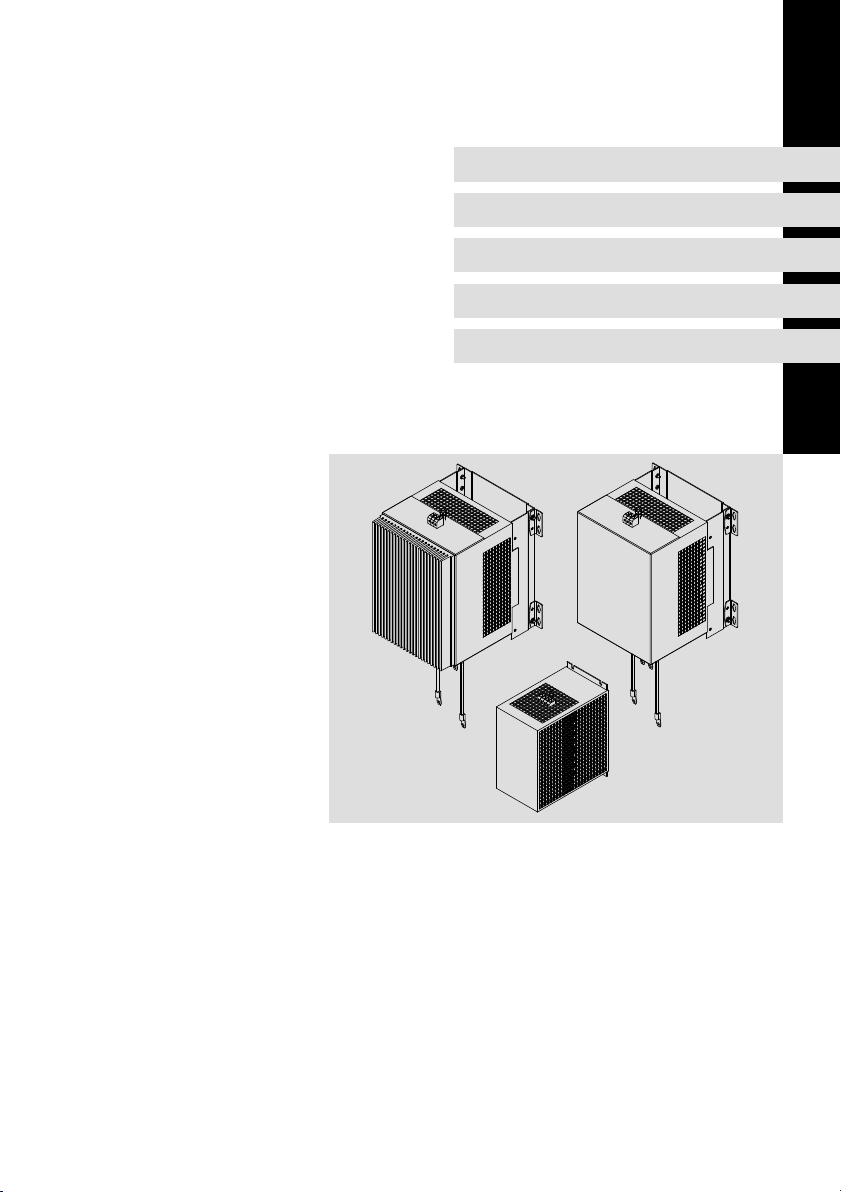
EZN 12 ... 45 A
EZN3A0120H012, EZN3A0088H024,
EZN3A0055H045, EZN3A0055H045U
Netzfilter
Mains filter
Filtre réseau
Page 2

Lesen Sie zuerst diese Anleitung und die Dokumentation zum
Grundgerät, bevor Sie mit den Arbeiten beginnen!
Beachten Sie die enthaltenen Sicherheitshinweise.
Please read these instructions and the documentation of the standard
device before you start working!
Observe the safety instructions given therein!
Lire le présent fascicule et la documentation relative à l’appareil de base
avant toute manipulation de l’équipement !
Respecter les consignes de sécurité fournies.
Page 3
EZN−071
Page 4
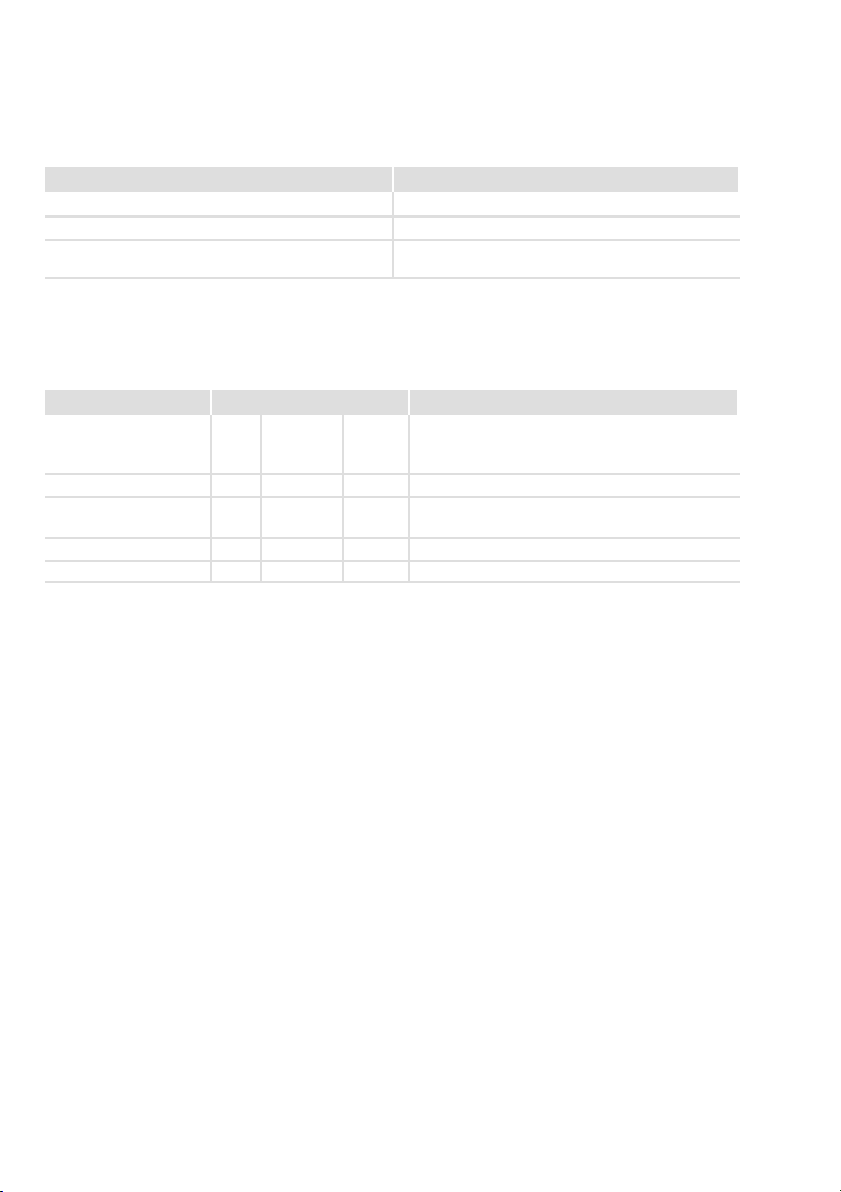
Lieferumfang
Anzahl Beschreibung
1 Filter
1 Montageanleitung
1 Nur EZN3A0055H045 und EZN3A0055H045U: Beipack mit ...
l 4 x Befestigungswinkel
4 x Schrauben M5 x 10 mm
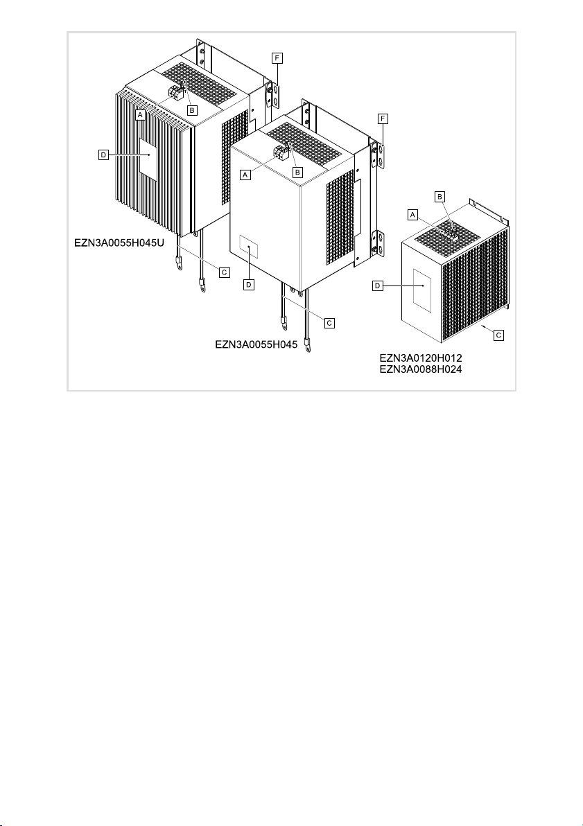
Elemente am Filter
Position Beschreibung
Netzanschluss
PE−Gewindebolzen
Anschluss Grundgerät
Typenschild
Befestigungswinkel
4
EDKZN3B045 DE/EN/FR 3.0
Page 5
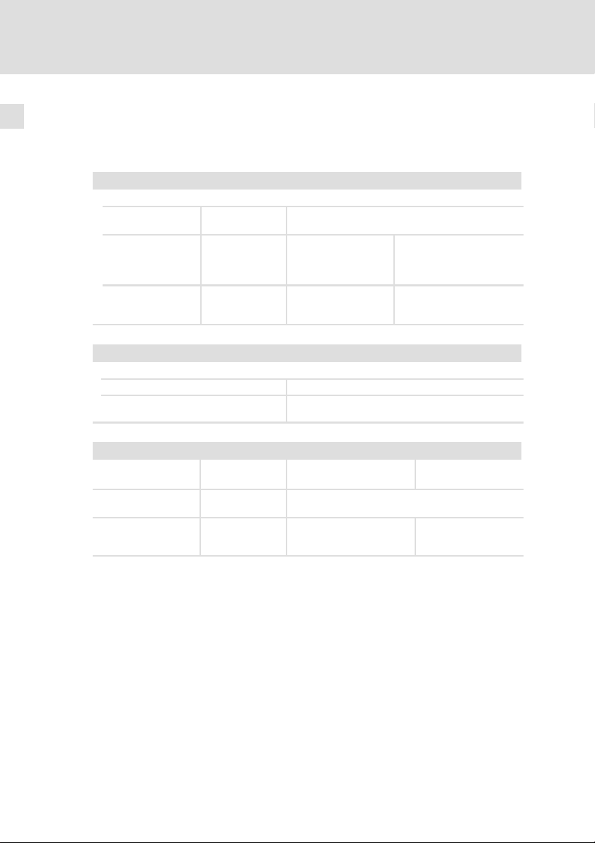
Informationen zur Gültigkeit
Diese Anleitung ist gültig für
ƒ Netzfilter EZN3A0120H012
ƒ Netzfilter EZN3A0088H024
ƒ Netzfilter EZN3A0550H045
ƒ Netzfilter EZN3A0550H045U
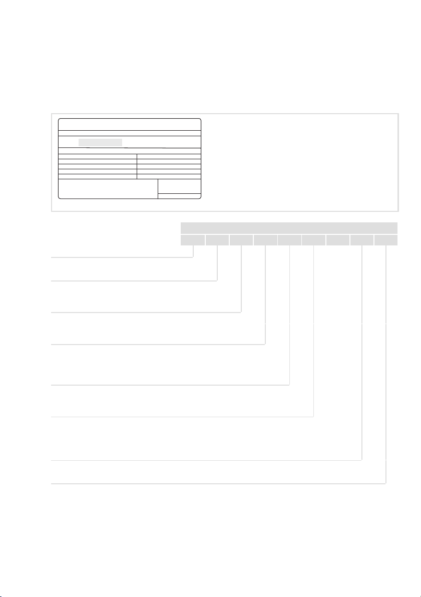
Identifikation
L
Type:
Typenschlüssel
Produktreihe
Zubehör
Filtertyp
N = Netzfilter
Anzahl Phasen
3 = 3 Phasen
Grenzwertklasse nach EN 61800−3
A = Grenzwertklasse C2
B = Grenzwertklasse C1
Induktivität
z. B. 0055 = 0,55 mH
Hans-Lenze-Straße 1
D-31855 Aerzen
Made in Germany
E Z N 3 x xxxx H xxx xxxx
8200vec080
Bemessungsstrom
z. B. 060 = 60 A
Filter−Variante (opt.)
EDKZN3B045 DE/EN/FR 3.0
5
Page 6
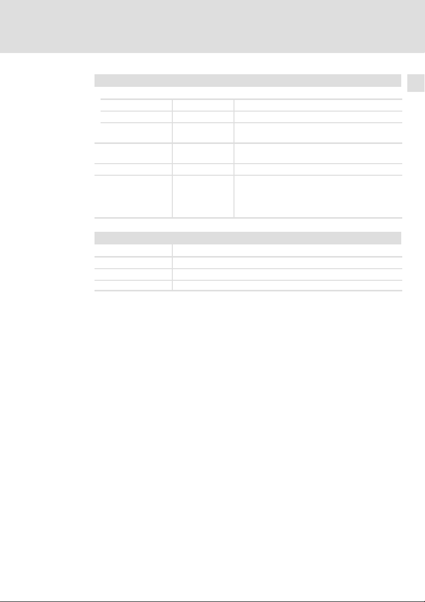
Einsatzbereich
Die Verwendung dieser Filter ist zulässig mit Grundgeräten gemäß nachfolgender Zuordnung.
Zuordnung Filter ˘ Grundgerät
Filter−Typ Rückspeiseeinheit−Typ
EZN3A0120H012 EMB9341
3)
Keine UR−Approbation
EZN3A0088H042 EMB9342
EZN3A0055H045
EZN3A0055H045U
3)
EMB9343
Dokumenthistorie
Materialnummer Version Beschreibung
.P@} 3.0 09/2014 TD29 UL−Hinweise in französischer Sprache für Canada
13287913 2.1 11/2011 TD29 Überarbeitung
13287913 2.0 02/2009 TD29 Neuauflage wegen Neuorganisation des Unterneh-
13216431 1.1 03/2008 TD29 DIN A4 à DIN A5
13216431 1.0 10/2007 TD29 Erstausgabe
EAC−Konformität
allgemeine Korrekturen
mens
Tipp!
Informationen und Hilfsmittel rund um die Lenze−Produkte finden Sie im
Download−Bereich unter
www.lenze.com
6
0Abb. 0Tab. 0
EDKZN3B045 DE/EN/FR 3.0
Page 7

Inhalt i
1 Sicherheitshinweise 8. . . . . . . . . . . . . . . . . . . . . . . . . . . . . . . . . . . . . . . . . . . . . . .
1.1 Verwendete Hinweise 8. . . . . . . . . . . . . . . . . . . . . . . . . . . . . . . . . . . . . . .
1.2 Restgefahren 9. . . . . . . . . . . . . . . . . . . . . . . . . . . . . . . . . . . . . . . . . . . . . .
2 Technische Daten 12. . . . . . . . . . . . . . . . . . . . . . . . . . . . . . . . . . . . . . . . . . . . . . . . .
2.1 Allgemeine Daten und Einsatzbedingungen 12. . . . . . . . . . . . . . . . . . . .
2.2 Bemessungsdaten 14. . . . . . . . . . . . . . . . . . . . . . . . . . . . . . . . . . . . . . . . . .
2.3 Mechanische Daten 15. . . . . . . . . . . . . . . . . . . . . . . . . . . . . . . . . . . . . . . .
3 Mechanische Installation 18. . . . . . . . . . . . . . . . . . . . . . . . . . . . . . . . . . . . . . . . . . .
3.1 Wichtige Hinweise 18. . . . . . . . . . . . . . . . . . . . . . . . . . . . . . . . . . . . . . . . . .
3.2 Bohrplan 19. . . . . . . . . . . . . . . . . . . . . . . . . . . . . . . . . . . . . . . . . . . . . . . . . .
3.3 Montageschritte 20. . . . . . . . . . . . . . . . . . . . . . . . . . . . . . . . . . . . . . . . . . .
4 Elektrische Installation 22. . . . . . . . . . . . . . . . . . . . . . . . . . . . . . . . . . . . . . . . . . . . .
4.1 Wichtige Hinweise 22. . . . . . . . . . . . . . . . . . . . . . . . . . . . . . . . . . . . . . . . . .
4.2 Anschlussplan 23. . . . . . . . . . . . . . . . . . . . . . . . . . . . . . . . . . . . . . . . . . . . .
4.3 Anschlussdaten 24. . . . . . . . . . . . . . . . . . . . . . . . . . . . . . . . . . . . . . . . . . . .
4.4 Montageschritte 24. . . . . . . . . . . . . . . . . . . . . . . . . . . . . . . . . . . . . . . . . . .
EDKZN3B045 DE/EN/FR 3.0
7
Page 8

1
Sicherheitshinweise
Verwendete Hinweise
1 Sicherheitshinweise
1.1 Verwendete Hinweise
Um auf Gefahren und wichtige Informationen hinzuweisen, werden in dieser
Dokumentation folgende Piktogramme und Signalwörter verwendet:
Sicherheitshinweise
Aufbau der Sicherheitshinweise:
Gefahr!
(kennzeichnet die Art und die Schwere der Gefahr)
Hinweistext
(beschreibt die Gefahr und gibt Hinweise, wie sie vermieden werden
kann)
Piktogramm und Signalwort Bedeutung
Gefahr!
Gefahr!
Stop!
Anwendungshinweise
Gefahr von Personenschäden durch gefährliche elektrische Spannung
Hinweis auf eine unmittelbar drohende Gefahr, die den
Tod oder schwere Verletzungen zur Folge haben kann,
wenn nicht die entsprechenden Maßnahmen getroffen
werden.
Gefahr von Personenschäden durch eine allgemeine
Gefahrenquelle
Hinweis auf eine unmittelbar drohende Gefahr, die den
Tod oder schwere Verletzungen zur Folge haben kann,
wenn nicht die entsprechenden Maßnahmen getroffen
werden.
Gefahr von Sachschäden
Hinweis auf eine mögliche Gefahr, die Sachschäden zur
Folge haben kann, wenn nicht die entsprechenden Maßnahmen getroffen werden.
Piktogramm und Signalwort Bedeutung
Hinweis!
Tipp!
8
Wichtiger Hinweis für die störungsfreie Funktion
Nützlicher Tipp für die einfache Handhabung
Verweis auf andere Dokumentation
EDKZN3B045 DE/EN/FR 3.0
Page 9

Sicherheitshinweise
Restgefahren
Spezielle Sicherheitshinweise und Anwendungshinweise
Piktogramm und Signalwort Bedeutung
1
Warnings!
Warnings!
1.2 Restgefahren
Gefahr!
Gefährliche elektrische Spannung
Alle Leistungsanschlüsse führen bis zu 3 Minuten nach
Netz−Ausschalten gefährliche elektrische Spannung.
Mögliche Folgen:
ƒ Tod oder schwere Verletzungen beim Berühren der
Leistungsanschlüsse.
Schutzmaßnahmen:
ƒ Vor Arbeiten an den Leistungsanschlüssen Netz abschalten und
mindestens 3 Minuten warten.
ƒ Prüfen, ob alle Leistungsanschlüsse spannungsfrei sind.
Sicherheitshinweis oder Anwendungshinweis für den
Betrieb nach UL− oder CSA−Anforderungen.
Die Maßnahmen sind erforderlich, um die Anforderungen nach UL oder CSA zu erfüllen.
EDKZN3B045 DE/EN/FR 3.0
9
Page 10

1
Sicherheitshinweise
Restgefahren
Gefahr!
Gefährliche elektrische Spannung
Der Ableitstrom gegen Erde (PE) ist > 3.5 mA AC bzw. > 10 mA DC.
Mögliche Folgen:
ƒ Tod oder schwere Verletzungen beim Berühren des Gerätes im
Fehlerfall.
Schutzmaßnahmen:
Die in der EN 61800−5−1 geforderten Maßnahmen umsetzen.
Insbesondere:
ƒ Festinstallation
– PE−Anschluss normgerecht ausführen.
– PE−Leiter doppelt auflegen oder PE−Leiterquerschnitt ³ 10 mm
ƒ Anschluss mit einem Steckverbinder für industrielle
Anwendungen nach IEC 60309 (CEE):
– PE−Leiterquerschnitt ³ 2.5 mm2 als Teil eines mehradrigen
Versorgungskabels.
– Angemessene Zugentlastung vorsehen.
Stop!
Kein Geräteschutz gegen zu hohe Netzspannung
Der Netzeingang ist intern nicht abgesichert.
Mögliche Folgen:
ƒ Zerstörung des Gerätes bei zu hoher Netzspannung.
Schutzmaßnahmen:
ƒ Beachten Sie die maximal zulässige Netzspannung.
ƒ Sichern Sie das Gerät netzseitig fachgerecht gegen
Netzschwankungen und Spannungsspitzen ab.
2
.
10
EDKZN3B045 DE/EN/FR 3.0
Page 11

Sicherheitshinweise
Restgefahren
Stop!
Hohes Gerätegewicht
Das Gerät ist sehr schwer und muss für die Montage angehoben
werden.
Mögliche Folgen:
ƒ Personenschäden, insbesondere Rückenschäden beim Anheben
bzw. Halten des Gerätes
ƒ Sach− und Personenschäden durch Herunterfallen des Gerätes
Schutzmaßnahmen:
ƒ Gerät nur mit einer für das Gerätegewicht zugelassenen
Lastaufnahmeeinrichtung (z. B. Hallenkran) transportieren.
ƒ Hebezeug, Lastaufnahmeeinrichtung und Anschlagmittel vor
dem Transport auf ausreichende Tragfähigkeit und
einwandfreien Zustand prüfen.
ƒ Hebezeug und Anschlagmittel erst entfernen, wenn das Gerät
sicher auf einem tragfähigen Untergrund aufliegt oder endgültig
montiert ist.
1
Warnings!
EDKZN3B045 DE/EN/FR 3.0
Conditions of Acceptability:
ƒ The filter EZN3A0120H012, EZN3A0088H024 and
EZN3A0055H045U shall be mounted into an enclosure providing
adequate spacings.
ƒ The terminals have not been evaluated for field wiring
connection.
ƒ These devices are only intended to be used with this
manufacturer’s inverters type EMB... having a controlled
overvoltage means as shown below:
– EZN3A0120H012 ® EMB9341−E
– EZN3A0088H024 ® EMB9342−E
– EZN3A0055H045U ® EMB9343−E
11
Page 12
2
Technische Daten
Allgemeine Daten und Einsatzbedingungen
2 Technische Daten
2.1 Allgemeine Daten und Einsatzbedingungen
Konformität und Approbation
Approbation
UL
EAC TP TC 020/2011
EAC TP TC 004/2011
Angaben zu Netzen
Netzformen
Mit geerdetem Y−Punkt (TT−/TN−Netze)
Andere Netzformen Anweisungen über besondere Maßnahmen in der
UL508 Industrial Control Equipment, Underwriter Laborato-
(TR ZU 020/2011)
(TR ZU 004/2011)
ries (File−No. E219022) for USA and Canada
Elektromagnetische
Verträglichkeit von
technischen Erzeugnissen
Über die Sicherheit
von Niederspannungsausrüstung
Betrieb uneingeschränkt erlaubt
Dokumentation zum Grundgerät beachten!
Eurasische Konformität
TR ZU: Technische Regulierung der Zollunion
Eurasische Konformität
TR ZU: Technische Regulierung der Zollunion
12
Schutz
Schutzart EN 60529 IP 20 nicht im Anschlussbe-
Isolationsfestigkeit EN 61800−5−1 Überspannungskategorie III
Reduzierung ab 2000 m: Überspannungskategorie II
Ableitstrom EN 61800−5−1 > 3.5 mA Bestimmungen und
reich der Klemmen
Sicherheitshinweise
beachten!
EDKZN3B045 DE/EN/FR 3.0
Page 13
Technische Daten
Allgemeine Daten und Einsatzbedingungen
Umweltbedingungen
Temperatur
Lagerung
Transport −25 ... +70 °C
Betrieb −10 ... +55 °C (Temperatur im Schaltschrank)
Aufstellhöhe 0 ... 4000 m üNN
Verschmutzung EN 61800−5−1 Verschmutzungsgrad 2
Rüttelfestigkeit EN50178;
Montagebedingungen
Montageort im Schaltschrank
Montageposition direkt über dem Grundgerät
Einbaulage senkrecht, Netzanschluss oben
Einbaufreiräume siehe "Mechanische Daten"
IEC61800−5−1;
Germanischer
Loyd, allgemeine
Bedingungen
−25 ... +60 °C
Stromreduzierung von +40 ... +55 °C: 2.5 %/°C
1000 ... 4000 m üNN: Stromreduzierung 5 %/1000 m
Beschleunigungsfest bis 0.7 g
2
EDKZN3B045 DE/EN/FR 3.0
13
Page 14
2
Technische Daten
Bemessungsdaten
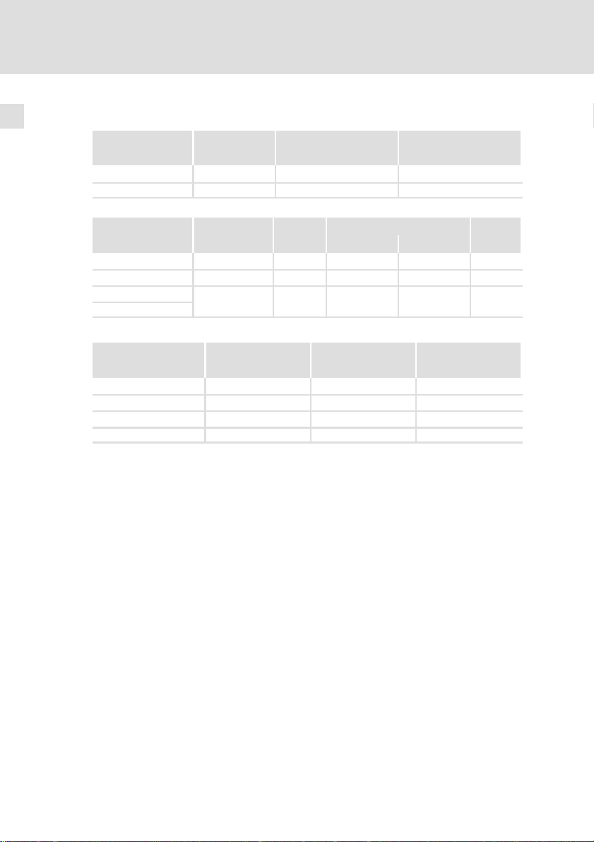
2.2 Bemessungsdaten
Netz Spannung Spannungsbereich Frequenzbereich
3/PE AC 400 320 − 0 % ... 440 + 0 % 45 − 0 % ... 65 + 0 %
3/PE AC 480 432 − 0 % ... 528 + 0 % 45 − 0 % ... 65 + 0 %
Typ
EZ...0120H012 400/480 50/60 12 7.5 3
EZ...0088H024 400/480 50/60 24 15 3
EZ...0055H045
EZ...0055H045U
Temperatur im Schaltschrank
EZ...0120H012 50 1.20 4.5
EZ...0088H024 95 0.88 6.6
EZ...0055H045 190 0.55 13.5
EZ...0055H045U 185 0.55 13.5
U
[V] U
LN
Spannung Frequenz Strom [A]
[V] [Hz] bis +40 °C bis +55 °C
400/480 50/60 45 28.1 3
Verlustleistung Induktivität Spannungsabfall
PV [W] L [mH] DU [V]
[V] f [Hz]
LN
Phasen-
zahl
14
EDKZN3B045 DE/EN/FR 3.0
Page 15
Technische Daten
Mechanische Daten
2
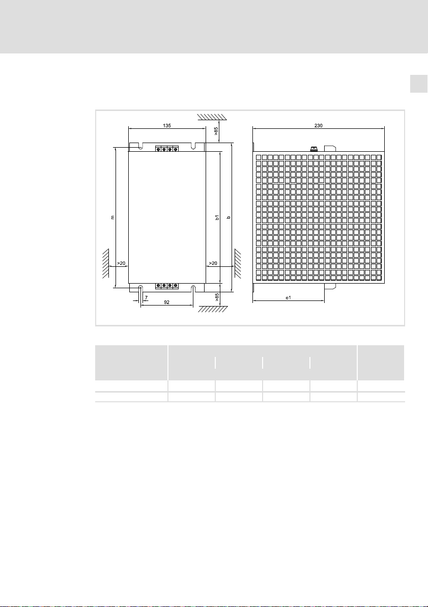
2.3 Mechanische Daten
Bauform 1
Alle Maße in Millimeter.
Typ
EZ...0120H012 230 260 125 245 10.1
EZ...0880H024 350 380 181 365 23.5
Maße
b b1 e1 m
[mm] [kg]
EZN−072a
Masse
EDKZN3B045 DE/EN/FR 3.0
15
Page 16
2
Technische Daten
Mechanische Daten
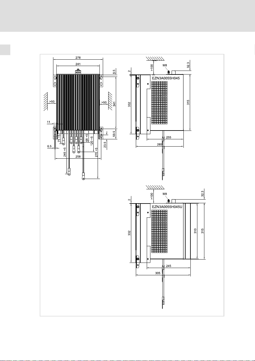
Bauform 2
16
Alle Maße in Millimeter.
EZN−072b
EDKZN3B045 DE/EN/FR 3.0
Page 17

Technische Daten
Mechanische Daten
Typ Masse [kg]
EZ...0055H045
EZ...0055H045U
41.0
2
EDKZN3B045 DE/EN/FR 3.0
17
Page 18

3
Mechanische Installation
Wichtige Hinweise
3 Mechanische Installation
3.1 Wichtige Hinweise
ƒ Der Montageort muss den in den Technischen Daten genannten
Einsatzbedingungen immer entsprechen ( 12). Ggf. zusätzliche
Maßnahmen ergreifen.
ƒ Die Montageplatte des Schaltschranks muss folgende Eigenschaften
aufweisen:
– elektrisch leitfähig
– lackfrei
ƒ Die mechanischen Verbindungen müssen immer gewährleistet sein.
ƒ Eine ungehinderte Luftzirkulation zum Abführen der Wärme muss
gewährleistet sein.
Stop!
Hohes Gerätegewicht
Das Gerät ist sehr schwer und muss für die Montage angehoben
werden.
Mögliche Folgen:
ƒ Personenschäden, insbesondere Rückenschäden beim Anheben
bzw. Halten des Gerätes
ƒ Sach− und Personenschäden durch Herunterfallen des Gerätes
Schutzmaßnahmen:
ƒ Gerät nur mit einer für das Gerätegewicht zugelassenen
Lastaufnahmeeinrichtung (z. B. Hallenkran) transportieren.
ƒ Hebezeug, Lastaufnahmeeinrichtung und Anschlagmittel vor
dem Transport auf ausreichende Tragfähigkeit und
einwandfreien Zustand prüfen.
ƒ Hebezeug und Anschlagmittel erst entfernen, wenn das Gerät
sicher auf einem tragfähigen Untergrund aufliegt oder endgültig
montiert ist.
18
EDKZN3B045 DE/EN/FR 3.0
Page 19
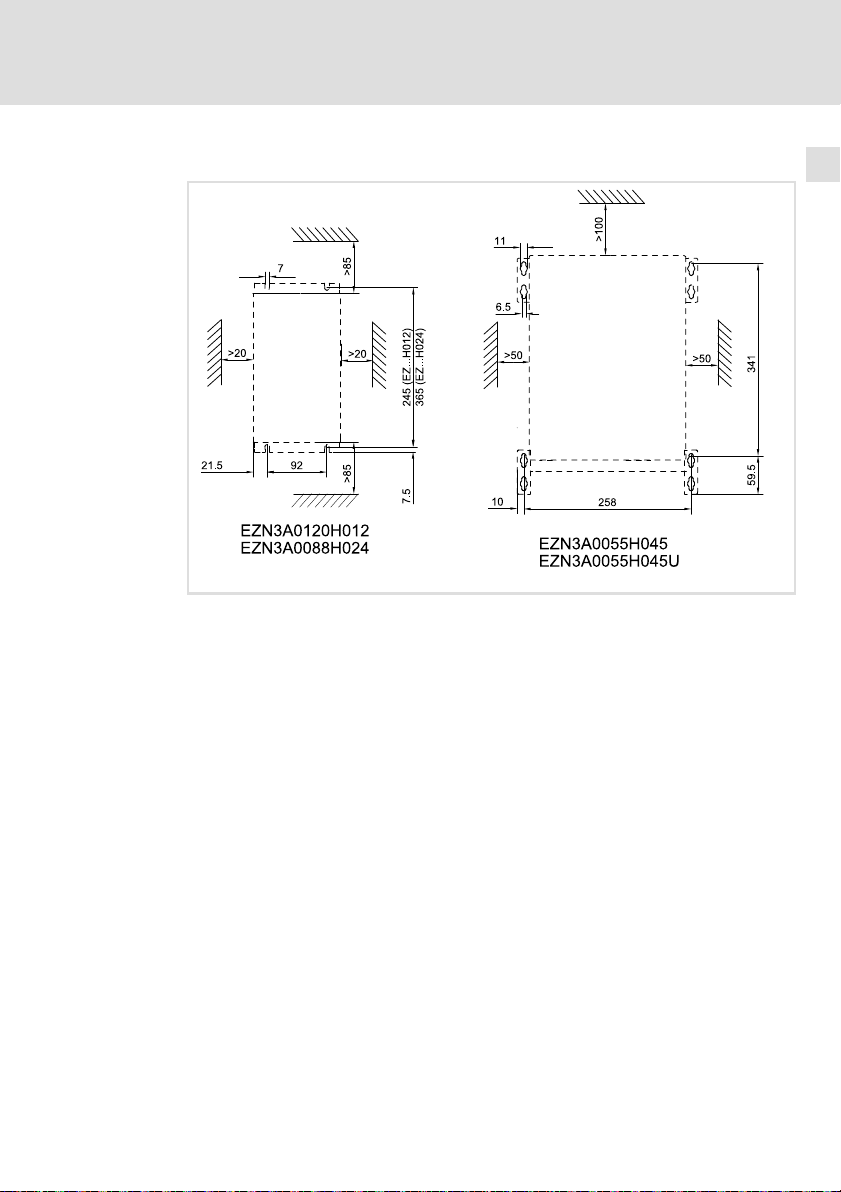
3.2 Bohrplan
Mechanische Installation
Bohrplan
3
EZN−073
EDKZN3B045 DE/EN/FR 3.0
19
Page 20
3
3.3 Montageschritte
Mechanische Installation
Montageschritte
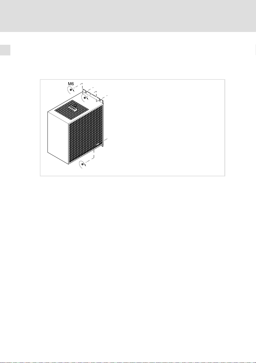
Bauform 1
ƒ EZN3A0120H012
ƒ EZN3A0088H024
So montieren Sie das Filter:
1. Montageplatte gemäß Bohrplan vorbereiten.
2. Filter mit 4 Schrauben M6 und Unterlegscheiben auf Montageplatte
montieren.
EZN−074
20
EDKZN3B045 DE/EN/FR 3.0
Page 21
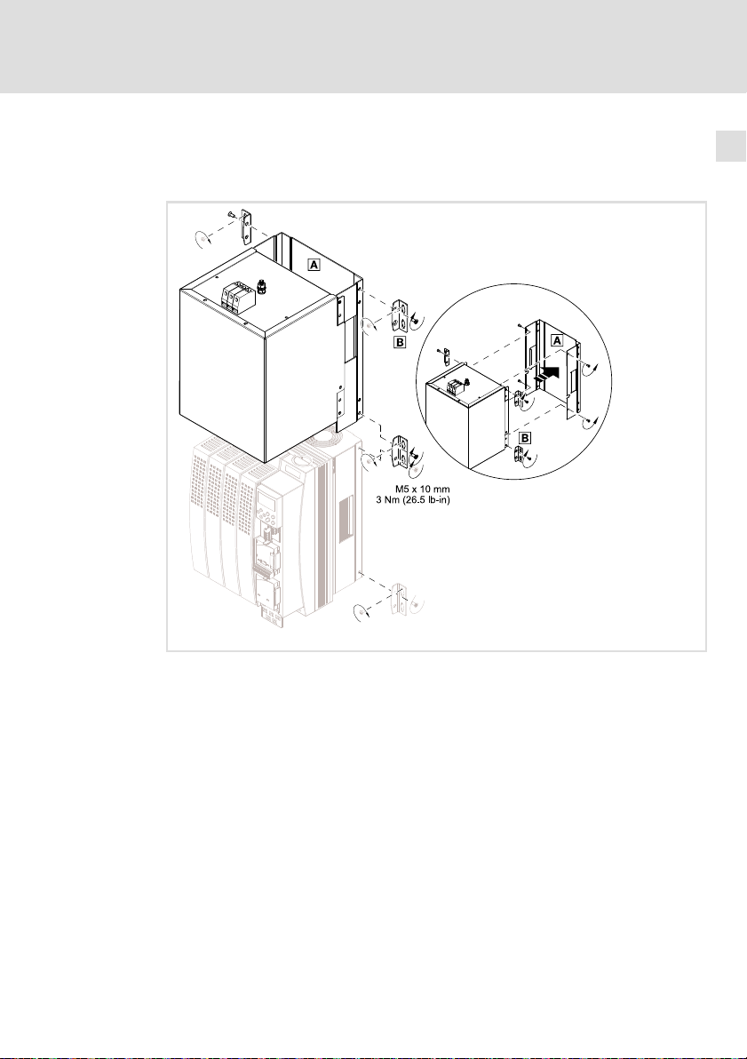
Bauform 2
ƒ EZN3A0055H045
ƒ EZN3A0055H045U
Mechanische Installation
Montageschritte
3
So montieren Sie das Filter:
1. Lesen Sie in der Dokumentation des Grundgerätes das Kapitel
"Mechanische Installation". Informieren Sie sich insbesondere über ...
– Vorsichtsmaßnahmen während der Montage
– das benötigte Montagematerial
– die vorgeschriebenen Anzugsmomente
– die Bohrabstände und Einbaufreiräume
2. Falls das Filter an Antriebsregler in Durchstoß− oder Cold−Plate−Technik
angeschlossen wird, Unterteil durch Lösen von 6 Schrauben
demontieren.
3. Vier Befestigungswinkel am Netzfilter montieren.
4. Netzfilter im Schaltschrank montieren.
EDKZN3B045 DE/EN/FR 3.0
EZN−034b
21
Page 22

4
Elektrische Installation
Wichtige Hinweise
4 Elektrische Installation
4.1 Wichtige Hinweise
ƒ Die Installation muss
– den in den Technischen Daten genannten Einsatzbedingungen immer
entsprechen ( 12).
– nach EN 60204−1 ausgeführt werden.
ƒ Bei der Auswahl des Leitungstyps beachten:
– Die verwendeten Leitungen müssen den geforderten Approbationen
am Einsatzort entsprechen (z. B. VDE, UL usw.).
– Absicherung und Leitungsquerschnitte gemäß den Vorgaben in der
Dokumentation zum Grundgerät bemessen.
ƒ Beim Verlegen der PE−Leitung beachten:
– Der PE−Anschluss muss nach EN 61800−5−1 ausgeführt werden.
22
EDKZN3B045 DE/EN/FR 3.0
Page 23

4.2 Anschlussplan
K1
L1
L2
L3
N
PE
Elektrische Installation
Anschlussplan
F
4
Antriebsregler
EZN...
0
PE
L1
Line
Load
L1'
PE
GN/YE
PE
L1
BK
L2
L2'
L2
BK
L3
L3'
BK
L3
EZN003
EDKZN3B045 DE/EN/FR 3.0
23
Page 24

4
Elektrische Installation
Anschlussdaten
4.3 Anschlussdaten
EZ...0120H012 0.2 ... 4 0.25 ... 4 0.5 ... 1.5 24 ... 10 8
EZ...0088H024 0.2 ... 6 0.25 ... 6 0.5 ... 4 24 ... 8 9
EZ...0055H045
EZ...0055H045U
4.4 Montageschritte
Bauform 1
ƒ EZN3A0120H012
ƒ EZN3A0088H024
[mm2] [AWG] [mm]
0.5 ... 16 0.5 ... 6 20 ... 4 16
[Nm]
[
lb−in]
0.6 ... 0.8
5.3 ... 7.1
1.5 ... 1.8
13.2 ... 15.9
2 ... 2.3
17.7 ...
20.35
24
EZN−075a
So verdrahten Sie das Filter:
1. Schaltschrank spannungsfrei schalten und gegen Wiedereinschalten
sichern.
2. Anschlussleitungen zum Grundgerät an Klemme "Load" anschließen .
– Montageanleitung des Grundgerätes beachten!
3. Netzleitungen an Klemme "Line" anschließen.
– Anzugsmoment beachten!
EDKZN3B045 DE/EN/FR 3.0
Page 25

Bauform 2
ƒ EZN3A0055H045
ƒ EZN3A0055H045U
Elektrische Installation
Montageschritte
4
So verdrahten Sie das Filter:
1. Schaltschrank spannungsfrei schalten und gegen wiedereinschalten
sichern.
2. Anschlussleitungen "Load" am Grundgerät anschließen.
– Montageanleitung des Grundgerätes beachten!
3. PE−Leiter mit Ringkabelschuh an PE−Gewindebolzen montieren.
– Anzugsmoment beachten!
4. Netzleitungen an Schraubklemme "Line" anschließen.
– Anzugsmoment beachten!
EDKZN3B045 DE/EN/FR 3.0
EZN−075b
25
Page 26

Scope of supply
Quantity Description
1 Filter
1 Mounting Instructions
1 EZN3A0055H045 and EZN3A0055H045U only: Accessory kit including ...
l 4 fixing brackets
4 screws M5 x 10 mm
Elements on the filter
Position Description
Mains connection
PE stud
Basic device connection
Nameplate
Fixing bracket
26
EDKZN3B045 DE/EN/FR 3.0
Page 27

Validity information
These instructions are valid for
ƒ Mains filter EZN3A0120H012
ƒ Mains filter EZN3A0088H024
ƒ Mains filter EZN3A0550H045
ƒ Mains filter EZN3A0550H045U
Identification
L
Type:
Type code
Product series
Accessories
Type of filter
N = mains filter
Number of phases
3 = 3 phases
Limit class according to EN 61800−3
A = limit class C2
B = limit class C1
Inductance
e.g. 0055 = 0.55 mH
Hans-Lenze-Straße 1
D-31855 Aerzen
Made in Germany
E Z N 3 x xxxx H xxx xxxx
8200vec080
Rated current
e.g. 060 = 60 A
Filter variant (opt.)
EDKZN3B045 DE/EN/FR 3.0
27
Page 28

Range of application
The application of these filters is permissible in standard devices according to the following
assignment.
Assignment of filters to standard devices
Filter type Regenerative module type
EZN3A0120H012 EMB9341
3)
No UR approval
EZN3A0088H042 EMB9342
EZN3A0055H045
EZN3A0055H045U
3)
EMB9343
Document history
Material number Version Description
.P@} 3.0 09/2014 TD29 UL notes in French for Canada
13287913 2.1 11/2011 TD29 Revision
13287913 2.0 02/2009 TD29 New edition due to reorganisation of the company
13216431 1.1 03/2008 TD29 DIN A4 à DIN A5
13216431 1.0 10/2007 TD29 First edition
EAC Conformity
General corrections
Tip!
Information and tools concerning the Lenze products can be found in the
download area under
www.lenze.com
0Fig. 0Tab. 0
28
EDKZN3B045 DE/EN/FR 3.0
Page 29

Contents i
1 Safety instructions 30. . . . . . . . . . . . . . . . . . . . . . . . . . . . . . . . . . . . . . . . . . . . . . . .
1.1 Notes used 30. . . . . . . . . . . . . . . . . . . . . . . . . . . . . . . . . . . . . . . . . . . . . . . .
1.2 Residual hazards 31. . . . . . . . . . . . . . . . . . . . . . . . . . . . . . . . . . . . . . . . . . .
2 Technical data 34. . . . . . . . . . . . . . . . . . . . . . . . . . . . . . . . . . . . . . . . . . . . . . . . . . . .
2.1 General data and operating conditions 34. . . . . . . . . . . . . . . . . . . . . . . .
2.2 Rated data 36. . . . . . . . . . . . . . . . . . . . . . . . . . . . . . . . . . . . . . . . . . . . . . . .
2.3 Mechanical data 37. . . . . . . . . . . . . . . . . . . . . . . . . . . . . . . . . . . . . . . . . .
3 Mechanical installation 40. . . . . . . . . . . . . . . . . . . . . . . . . . . . . . . . . . . . . . . . . . . .
3.1 Important notes 40. . . . . . . . . . . . . . . . . . . . . . . . . . . . . . . . . . . . . . . . . . . .
3.2 Drilling pattern 41. . . . . . . . . . . . . . . . . . . . . . . . . . . . . . . . . . . . . . . . . . . .
3.3 Mounting steps 42. . . . . . . . . . . . . . . . . . . . . . . . . . . . . . . . . . . . . . . . . . . .
4 Electrical installation 44. . . . . . . . . . . . . . . . . . . . . . . . . . . . . . . . . . . . . . . . . . . . . .
4.1 Important notes 44. . . . . . . . . . . . . . . . . . . . . . . . . . . . . . . . . . . . . . . . . . . .
4.2 Connection plan 45. . . . . . . . . . . . . . . . . . . . . . . . . . . . . . . . . . . . . . . . . . . .
4.3 Connection data 46. . . . . . . . . . . . . . . . . . . . . . . . . . . . . . . . . . . . . . . . . . . .
4.4 Mounting steps 46. . . . . . . . . . . . . . . . . . . . . . . . . . . . . . . . . . . . . . . . . . . .
EDKZN3B045 DE/EN/FR 3.0
29
Page 30

1
Safety instructions
Notes used
1 Safety instructions
1.1 Notes used
The following pictographs and signal words are used in this documentation to
indicate dangers and important information:
Safety instructions
Structure of safety instructions:
Danger!
(characterises the type and severity of danger)
Note
(describes the danger and gives information about how to prevent
dangerous situations)
Pictograph and signal word Meaning
Danger!
Danger!
Stop!
Application notes
Danger of personal injury through dangerous electrical
voltage.
Reference to an imminent danger that may result in
death or serious personal injury if the corresponding
measures are not taken.
Danger of personal injury through a general source of
danger.
Reference to an imminent danger that may result in
death or serious personal injury if the corresponding
measures are not taken.
Danger of property damage.
Reference to a possible danger that may result in
property damage if the corresponding measures are not
taken.
30
Pictograph and signal word Meaning
Note!
Tip!
Important note to ensure troublefree operation
Useful tip for simple handling
Reference to another documentation
EDKZN3B045 DE/EN/FR 3.0
Page 31

Safety instructions
Special safety instructions and application notes
Pictograph and signal word Meaning
1
Residual hazards
Warnings!
Warnings!
1.2 Residual hazards
Danger!
Dangerous electrical voltage
All power terminals remain live for up to three minutes after mains
disconnection.
Possible consequences:
ƒ Death or severe injuries when touching the power terminals.
Protective measures:
ƒ Switch off the power supply and wait for at least three minutes
before working on the power terminals.
ƒ Make sure that all power terminals are deenergised.
Safety note or application note for the operation
according to UL or CSA requirements.
The measures are required to meet the requirements
according to UL or CSA.
EDKZN3B045 DE/EN/FR 3.0
31
Page 32

1
Safety instructions
Residual hazards
Danger!
Hazardous electrical voltage
The leakage current to earth (PE) is > 3.5 mA AC or > 10 mA DC.
Possible consequences:
ƒ Death or severe injuries when touching the device in the event of
an error.
Protective measures:
Implement the measures required in EN 61800−5−1. Especially:
ƒ Fixed installation
– Implement PE connection in compliance with standards.
– Connect PE conductor twice or PE conductor cross−section
³ 10 mm
ƒ Connection with a connector for industrial applications according
to IEC 60309 (CEE):
– PE conductor cross−section ³ 2.5 mm2 as part of a multi−core
supply cable.
– Provide for suitable strain relief.
Stop!
No device protection if the mains voltage is too high
The mains input is not internally fused.
Possible consequences:
ƒ Destruction of the device if the mains voltage is too high.
Protective measures:
ƒ Observe the maximally permissible mains voltage.
ƒ Fuse the device correctly on the supply side against mains
fluctuations and voltage peaks.
2
.
32
EDKZN3B045 DE/EN/FR 3.0
Page 33

Safety instructions
Residual hazards
Stop!
Heavy device weight
The device is very heavy and must be lifted for the mounting.
Possible consequences:
ƒ Injury to persons, particularly backache when lifting and holding
the device, respectively
ƒ Injury to persons and damage to material assets due to the
device falling down
Protective measures:
ƒ The device must only be carried with a load bearing system such
as an indoor crane permitted for the device weight
ƒ Before the transport, the hoist, the load bearing system and
lifting accessories must be checked for sufficient payload and
faultless status
ƒ Do not remove the hoist and the lifting accessories until the
device lies safe on a stable surface or is finally mounted.
Warnings!
Conditions of Acceptability:
ƒ The filter EZN3A0120H012, EZN3A0088H024 and
EZN3A0055H045U shall be mounted into an enclosure providing
adequate spacings.
ƒ The terminals have not been evaluated for field wiring
connection.
ƒ These devices are only intended to be used with this
manufacturer’s inverters type EMB... having a controlled
overvoltage means as shown below:
– EZN3A0120H012 ® EMB9341−E
– EZN3A0088H024 ® EMB9342−E
– EZN3A0055H045U ® EMB9343−E
1
EDKZN3B045 DE/EN/FR 3.0
33
Page 34

2
Technical data
General data and operating conditions
2 Technical data
2.1 General data and operating conditions
Conformity and approval
Approval
UL
EAC TP TC 020/2011
EAC TP TC 004/2011
Mains data
Mains types
With grounded neutral (TT/TN systems)
Other mains types Observe instructions for special measures in the
UL508 Industrial Control Equipment, Underwriter
(TR CU 020/2011)
(TR CU 004/2011)
Laboratories (File−No. E219022) for USA and Canada
Electromagnetic
compatibility of
technical means
On safety of low
voltage equipment
Operation permitted without restrictions
documentation for the basic device!
Protection
Degree of protection EN 60529
Insulation resistance EN 61800−5−1 Overvoltage category III
Leakage current EN 61800−5−1 > 3.5 mA Observe regulations
IP 20 Not in the wire range
> 2000 m: Overvoltage category II
Eurasian Conformity
TR CU: Technical Regulation
of Customs Union
Eurasian Conformity
TR CU: Technical Regulation
of Customs Union
of the terminals
and safety
instructions!
34
EDKZN3B045 DE/EN/FR 3.0
Page 35

Technical data
General data and operating conditions
Ambient conditions
Temperature
Storage
Transport −25 ... +70 °C
Operation −10 ... +55 °C (Temperature in the control cabinet)
Site altitude 0 ... 4000 m amsl
Pollution EN 61800−5−1 Pollution degree 2
Vibration resistance EN 50178; IEC
Mounting conditions
Mounting location In the control cabinet
Mounting position Directly above the standard device
Mounting position Vertical, mains connection on top
Free spaces See "Mechanical data"
61800−5−1;
Germanischer
Lloyd, general
conditions
−25 ... +60 °C
Current derating from +40 ... +55 °C: 2.5 %/°C
1000 ... 4000 m amsl: Current derating by
5 %/1000 m
Acceleration−resistant up to 0.7 g
2
EDKZN3B045 DE/EN/FR 3.0
35
Page 36

2
Technical data
Rated data
2.2 Rated data
Mains Voltage Voltage range Frequency range
3/PE AC 400 320 − 0 % ... 440 + 0 % 45 − 0 % ... 65 + 0 %
3/PE AC 480 432 − 0 % ... 528 + 0 % 45 − 0 % ... 65 + 0 %
Type
EZ...0120H012 400/480 50/60 12 7.5 3
EZ...0088H024 400/480 50/60 24 15 3
EZ...0055H045
EZ...0055H045U
Temperature in the control cabinet
EZ...0120H012 50 1.20 4.5
EZ...0088H024 95 0.88 6.6
EZ...0055H045 190 0.55 13.5
EZ...0055H045U 185 0.55 13.5
U
[V] U
Lrated
Voltage Frequency Current [A]
[V] [Hz] up to +40 °C up to +55 °C
400/480 50/60 45 28.1 3
Power loss Inductance Voltage drop
P
[W] L [mH] DU [V]
loss
[V] f [Hz]
Lrated
Number
of phases
36
EDKZN3B045 DE/EN/FR 3.0
Page 37

Technical data
Mechanical data
2
2.3 Mechanical data
Design 1
All dimensions in millimetres.
Type
EZ...0120H012 230 260 125 245 10.1
EZ...0880H024 350 380 181 365 23.5
Dimensions
b b1 e1 m
[mm] [kg]
EZN−072a
Weight
EDKZN3B045 DE/EN/FR 3.0
37
Page 38

2
Technical data
Mechanical data
Design 2
38
All dimensions in millimetres.
EZN−072b
EDKZN3B045 DE/EN/FR 3.0
Page 39

Technical data
Type Mass [kg]
EZ...0055H045
EZ...0055H045U
41.0
2
Mechanical data
EDKZN3B045 DE/EN/FR 3.0
39
Page 40

3
Mechanical installation
Important notes
3 Mechanical installation
3.1 Important notes
ƒ The mounting location must always comply with the operating conditions
specified in the technical data ( 34). Take additional measures if
necessary.
ƒ The mounting plate of the control cabinet must have the following
properties:
– electrically conductive
– free of lacquer
ƒ The mechanical connections must always be ensured.
ƒ A free air circulation must be ensured for dissipating the heat.
Stop!
Heavy device weight
The device is very heavy and must be lifted for the mounting.
Possible consequences:
ƒ Injury to persons, particularly backache when lifting and holding
the device, respectively
ƒ Injury to persons and damage to material assets due to the
device falling down
Protective measures:
ƒ The device must only be carried with a load bearing system such
as an indoor crane permitted for the device weight
ƒ Before the transport, the hoist, the load bearing system and
lifting accessories must be checked for sufficient payload and
faultless status
ƒ Do not remove the hoist and the lifting accessories until the
device lies safe on a stable surface or is finally mounted.
40
EDKZN3B045 DE/EN/FR 3.0
Page 41

3.2 Drilling pattern
Mechanical installation
Drilling pattern
3
EZN−073
EDKZN3B045 DE/EN/FR 3.0
41
Page 42

3
3.3 Mounting steps
Mechanical installation
Mounting steps
Design 1
ƒ EZN3A0120H012
ƒ EZN3A0088H024
How to mount the filter:
1. Prepare the mounting plate as shown in the drilling pattern.
2. Mount the filter to the mounting plate using 4 M6 screws and washers.
EZN−074
42
EDKZN3B045 DE/EN/FR 3.0
Page 43

Design 2
ƒ EZN3A0055H045
ƒ EZN3A0055H045U
Mechanical installation
Mounting steps
3
How to mount the filter:
1. Read the chapter "Mechanical installation" in the documentation of the
basic device. Read up particularly on ...
– Precautionary measures while mounting
– Installation material required
– Compulsory starting torques
– Bore spacings and free spaces
2. If the filter is connected to the controller in push−through technique or
cold−plate technique, remove the bottom part by releasing 6 screws.
3. Mount four fixing brackets to the mains filter.
4. Mount the mains filter in the control cabinet.
EDKZN3B045 DE/EN/FR 3.0
EZN−034b
43
Page 44

4
Electrical installation
Important notes
4 Electrical installation
4.1 Important notes
ƒ Installation must
– always be in accordance with the operating conditions specified in the
Technical data ( 34).
– be carried out to EN 60204−1.
ƒ Please observe the following when selecting the cable type:
– The cables used must comply with the approvals required for the
application (e. g. VDE, UL etc.).
– Fuses and cable cross−sections must be dimensioned in accordance with
the specifications in the documentation for the basic device.
ƒ Please observe the following when laying the PE cable:
– The PE connection must comply with EN 61800−5−1.
44
EDKZN3B045 DE/EN/FR 3.0
Page 45

4.2 Connection plan
K1
L1
L2
L3
N
PE
Electrical installation
Connection plan
F
4
Controller
EZN...
0
PE
L1
Line
Load
L1'
PE
GN/YE
PE
L1
BK
L2
L2'
L2
BK
L3
L3'
BK
L3
EZN003
EDKZN3B045 DE/EN/FR 3.0
45
Page 46

4
Electrical installation
Connection data
4.3 Connection data
EZ...0120H012 0.2 ... 4 0.25 ... 4 0.5 ... 1.5 24 ... 10 8
EZ...0088H024 0.2 ... 6 0.25 ... 6 0.5 ... 4 24 ... 8 9
EZ...0055H045
EZ...0055H045U
4.4 Mounting steps
Design 1
ƒ EZN3A0120H012
ƒ EZN3A0088H024
[mm2] [AWG] [mm]
0.5 ... 16 0.5 ... 6 20 ... 4 16
[Nm]
[
lb−in]
0.6 ... 0.8
5.3 ... 7.1
1.5 ... 1.8
13.2 ... 15.9
2 ... 2.3
17.7 ...
20.35
46
EZN−075a
How to wire the filter:
1. Deenergise the control cabinet and fuse it against re−energisation.
2. Connect the connection cables of the standard device to terminal "Load"
.
– Observe the documentation of the standard device!
3. Connect the mains cables to terminal "Line" .
– Observe tightening torque!
EDKZN3B045 DE/EN/FR 3.0
Page 47

Design 2
ƒ EZN3A0055H045
ƒ EZN3A0055H045U
Electrical installation
Mounting steps
4
How to wire the filter:
1. Deenergise the control cabinet and fuse it against re−energisation.
2. Connect the connection cables "load" to the basic device.
– Observe the mounting instructions for the basic device!
3. Attach the PE conductor to the PE stud with the ring cable lug.
– Observe tightening torque!
4. Connect the mains cables to the screw terminal "line" .
– Observe tightening torque!
EDKZN3B045 DE/EN/FR 3.0
EZN−075b
47
Page 48

Équipement livré
Nombre Description
1 Filtre
1 Instructions de montage
1 Uniquement filtres EZN3A0055H045 et EZN3A0055H045U : kit de montage comprenant...
l 4 x équerres de fixation
4 x vis M5 x 10 mm
Eléments du filtre
Position Description
Raccordement réseau
Boulons filtetés PE
Raccordement de l’appareil de base
Plaque signalétique
Equerres de fixation
48
EDKZN3B045 DE/EN/FR 3.0
Page 49

Validité
Le présent document s’applique au produits suivants :
ƒ Filtre réseau EZN3A0120H012
ƒ Filtre réseau EZN3A0088H024
ƒ Filtre réseau EZN3A0550H045
ƒ Filtre réseau EZN3A0550H045U
Identification
L
Type:
Codification des types
Série d’appareils
Accessoires
Type de filtre
N = filtre réseau
Nombre de phases
3 = 3 phases
Classe d’antiparasitage suivant EN 61800−3
A = classe C2
B = classe C1
Inductance
Ex. : 0055 = 0,55 mH
Hans-Lenze-Straße 1
D-31855 Aerzen
Made in Germany
E Z N 3 x xxxx H xxx xxxx
8200vec080
Courant nominal
Ex. : 060 = 60 A
Variante de filtre (opt.)
EDKZN3B045 DE/EN/FR 3.0
49
Page 50

Domaine d’utilisation
Les combinaisons filtre−appareil de base suivantes peuvent être réalisées.
Combinaisons entre les filtres et les appareils de base
Type de filtre Type d’unité de renvoi sur le réseau
EZN3A0120H012 EMB9341
3)
Sans homologation UR
EZN3A0088H042 EMB9342
EZN3A0055H045
EZN3A0055H045U
3)
EMB9343
Historique du document
Numéro de matériel Version Description
.P@} 3.0 09/2014 TD29 Consignes UL en français pour le Canada
13287913 2.1 11/2011 TD29 Edition revue
13287913 2.0 02/2009 TD29 Nouvelle édition en raison de la nouvelle
13216431 1.1 03/2008 TD29 DIN A4 à DIN A5
13216431 1.0 10/2007 TD29 Première édition
Conformité EAC
Corrections générales
organisation de l’entreprise
Conseil !
Toutes les informations relatives aux produits Lenze peuvent être téléchargées
sur notre site à l’adresse suivante :
www.Lenze.com
0Fig. 0Tab. 0
50
EDKZN3B045 DE/EN/FR 3.0
Page 51

Sommaire i
1 Consignes de sécurité 52. . . . . . . . . . . . . . . . . . . . . . . . . . . . . . . . . . . . . . . . . . . . . .
1.1 Consignes utilisées 52. . . . . . . . . . . . . . . . . . . . . . . . . . . . . . . . . . . . . . . . .
1.2 Dangers résiduels 53. . . . . . . . . . . . . . . . . . . . . . . . . . . . . . . . . . . . . . . . . .
2 Spécifications techniques 56. . . . . . . . . . . . . . . . . . . . . . . . . . . . . . . . . . . . . . . . . .
2.1 Caractéristiques générales et conditions d’utilisation 56. . . . . . . . . . . .
2.2 Caractéristiques assignées 58. . . . . . . . . . . . . . . . . . . . . . . . . . . . . . . . . . .
2.3 Caractéristiques mécaniques 59. . . . . . . . . . . . . . . . . . . . . . . . . . . . . . . .
3 Installation mécanique 62. . . . . . . . . . . . . . . . . . . . . . . . . . . . . . . . . . . . . . . . . . . .
3.1 Remarques importantes 62. . . . . . . . . . . . . . . . . . . . . . . . . . . . . . . . . . . . .
3.2 Modèle de perçage 63. . . . . . . . . . . . . . . . . . . . . . . . . . . . . . . . . . . . . . . . . .
3.3 Opérations de montage 64. . . . . . . . . . . . . . . . . . . . . . . . . . . . . . . . . . . . . .
4 Installation électrique 66. . . . . . . . . . . . . . . . . . . . . . . . . . . . . . . . . . . . . . . . . . . . .
4.1 Remarques importantes 66. . . . . . . . . . . . . . . . . . . . . . . . . . . . . . . . . . . . .
4.2 Schéma de câblage 67. . . . . . . . . . . . . . . . . . . . . . . . . . . . . . . . . . . . . . . . .
4.3 Données de raccordement 68. . . . . . . . . . . . . . . . . . . . . . . . . . . . . . . . . . .
4.4 Opérations de montage 68. . . . . . . . . . . . . . . . . . . . . . . . . . . . . . . . . . . . . .
EDKZN3B045 DE/EN/FR 3.0
51
Page 52

1
Consignes de sécurité
Consignes utilisées
1 Consignes de sécurité
1.1 Consignes utilisées
Pour indiquer des risques et des informations importantes, la présente
documentation utilise les mots et pictogrammes suivants :
Consignes de sécurité
Présentation des consignes de sécurité
Danger !
(Le pictogramme indique le type de risque.)
Explication
(L’explication décrit le risque et les moyens de l’éviter.)
Pictogramme et mot associé Explication
Danger !
Danger !
Stop !
Consignes d’utilisation
Situation dangereuse pour les personnes en raison
d’une tension électrique élevée
Indication d’un danger imminent qui peut avoir pour
conséquences des blessures mortelles ou très graves en
cas de non−respect des consignes de sécurité
correspondantes
Situation dangereuse pour les personnes en raison d’un
danger d’ordre général
Indication d’un danger imminent qui peut avoir pour
conséquences des blessures mortelles ou très graves en
cas de non−respect des consignes de sécurité
correspondantes
Risques de dégâts matériels
Indication d’un risque potentiel qui peut avoir pour
conséquences des dégâts matériels en cas de
non−respect des consignes de sécurité correspondantes
52
Pictogramme et mot associé Explication
Remarque
importante !
Conseil !
Remarque importante pour assurer un fonctionnement
correct
Conseil utile pour faciliter la mise en uvre
Renvoi à une autre documentation
EDKZN3B045 DE/EN/FR 3.0
Page 53

Consignes de sécurité
Consignes de sécurité et d’utilisation spéciales
Pictogramme et mot associé Description
1
Dangers résiduels
Avertissements !
Avertissements !
1.2 Dangers résiduels
Danger !
Tension électrique dangereuse
Les raccordements de puissance sont encore sous tension jusqu’à 3
minutes après la coupure réseau.
Risques encourus :
ƒ Mort ou blessures graves en cas de contact accidentel avec les
raccordements de puissance.
Mesures de protection :
ƒ Avant toute intervention au niveau des raccordements de
puissance, couper l’alimentation et attendre au moins 3 minutes.
ƒ S’assurer que tous les raccordements de puissance sont hors
tension.
Consigne de sécurité ou d’utilisation pour le
fonctionnement selon les normes UL ou CSA.
Les mesures sont requises pour répondre aux exigences
des normes UL ou CSA.
EDKZN3B045 DE/EN/FR 3.0
53
Page 54

1
Consignes de sécurité
Dangers résiduels
Danger !
Tension électrique dangereuse
Le courant de fuite vers la terre (PE) est > 3.5 mA CA ou > 10 mA CC.
Risques encourus :
ƒ Mort ou blessures graves en cas de contact accidentel avec
l’appareil en défaut
Mesures de protection :
Mettre en œuvre les mesures prescrites par la norme EN 61800−5−1,
notamment :
ƒ Installation fixe
– Prévoir un raccordement PE conformément à la norme.
– Prévoir un double raccordement du câble PE ou une section de
câble PE ³ 10 mm
ƒ Raccordement à l’aide d’un connecteur adapté aux applications
industrielles selon la norme CEI 60309 (CEE)
– La section de câble PE ³ 2.5 mm
câble d’alimentation multiconducteur.
– Utiliser un dispositif de décharge de traction adapté.
2
.
2
représente une partie du
54
Stop !
Appareil non protégé contre une tension réseau trop élevée
Il n’y a pas de protection intégrée de l’entrée réseau.
Risques encourus :
ƒ Dommages irréversibles de l’appareil en cas de tension réseau
trop élevée
Mesures de protection :
ƒ Respecter la tension réseau maximale admissible.
ƒ Protéger l’appareil de manière adaptée côté réseau contre les
fluctuations du réseau et les pointes de tension.
EDKZN3B045 DE/EN/FR 3.0
Page 55

Consignes de sécurité
Dangers résiduels
Stop !
Appareil lourd
Cet appareil est très lourd et doit être soulevé pour le montage.
Risques encourus :
ƒ Blessures, notamment lombalgies causées par le fait de soulever
ou de maintenir l’appareil
ƒ Blessures et dommages matériels causés par une chute de
l’appareil
Mesures de protection :
ƒ Transporter l’appareil uniquement avec une installation de
suspension homologuée pour le poids de l’appareil (grue
d’entrepot par exemple).
ƒ Contrôler avant le transport la force de levage et l’état de
fonctionnement de l’appareil de levage, de l’installation de
suspension de charge et du dispositif de butée.
ƒ L’appareil de levage et le dispositif de butée ne doivent être
retirés que si l’appareil repose sur un support solide ou est
monté.
1
Avertissements !
EDKZN3B045 DE/EN/FR 3.0
Conditions d’acceptabilité :
ƒ Les filtres EZN3A0120H012, EZN3A0088H024 et
EZN3A0055H045U doivent être montés dans un coffret de
protection en respectant les espacements minimums prescrits.
ƒ Les bornes n’ont pas été évaluées pour le raccordement d’un
câblage à pied d’oeuvre.
ƒ Ces appareils sont destinés exclusivement à être utilisés avec des
variateurs de ce fabricant de type EMB... avec une surtension
contrôlée (voir ci−après) :
– EZN3A0120H012 ®EMB9341−E
– EZN3A0088H024 ®EMB9342−E
– EZN3A0055H045U ®EMB9343−E
55
Page 56

2
Spécifications techniques
Caractéristiques générales et conditions d’utilisation
2 Spécifications techniques
2.1 Caractéristiques générales et conditions d’utilisation
Conformité et homologation
Homologation
UL508 Industrial Control Equipment, Underwriter
(RT UD 020/2011)
(RT UD 004/2011)
Laboratories (File−No. E219022) for USA and Canada
Compatibilité
électromagnétique des
équipements
Sécurité des
équipements à basse
tension
Utilisation sans restriction
particulières dans la documentation de l’appareil de
base !
UL
EAC TP TC 020/2011
EAC TP TC 004/2011
Informations sur les réseaux
Configurations réseau
Avec point Y à la terre (réseaux TT/TN)
Autres configurations réseau Respecter les indications concernant les mesures
Conformité eurasienne
RT UD : Règlement
technique de l’Union
Douanière
Conformité eurasienne
RT UD : Règlement
technique de l’Union
Douanière
56
Protection
Indice de protection EN 60529
Résistance d’isolement EN 61800−5−1 Catégorie de surtension III
Courant de fuite EN 61800−5−1 > 3.5 mA Tenir compte des
IP 20 Pas dans la zone de
Réduction à partir de 2000 m : catégorie de
surtension II
raccordement des
bornes
prescriptions et des
consignes de sécurité !
EDKZN3B045 DE/EN/FR 3.0
Page 57

Spécifications techniques
Caractéristiques générales et conditions d’utilisation
Conditions climatiques
Température
Stockage
Transport −25 ... +70 °C
Fonctionnement −10 ... +55 °C (température dans l’armoire électrique)
Altitude
d’implantation
Pollution ambiante
admissible
Résistance aux chocs EN50178 ;
Conditions de montage
Lieu de montage Armoire électrique
Position de montage Sur l’appareil de base
Position de montage Verticale, raccordement réseau vers le haut
Espaces de montage Voir "Caractéristiques mécaniques"
EN 61800−5−1 Degré de pollution 2
IEC61800−5−1 ;
Germanischer
Loyd, Conditions
générales
−25 ... +60 °C
Réduction de courant dans la plage +40 ... +55 °C :
2,5 %/°C
0 ... 4000 m au−dessus du niveau de la mer
1000 ... 4000 m au−dessus du niveau de la mer :
réduction de courant de 5 %/1000 m
Résistance à l’accélération jusqu’à 0,7 g
2
EDKZN3B045 DE/EN/FR 3.0
57
Page 58

2
Spécifications techniques
Caractéristiques assignées
2.2 Caractéristiques assignées
Réseau Tension Plage de tension Plage de fréquence
3/PE CA 400 320 − 0 % ... 440 + 0 % 45 − 0 % ... 65 + 0 %
3/PE CA 480 432 − 0 % ... 528 + 0 % 45 − 0 % ... 65 + 0 %
Type
EZ...0120H012 400/480 50/60 12 7.5 3
EZ...0088H024 400/480 50/60 24 15 3
EZ...0055H045
EZ...0055H045U
Température dans l’armoire électrique
EZ...0120H012 50 1.20 4.5
EZ...0088H024 95 0.88 6.6
EZ...0055H045 190 0.55 13.5
EZ...0055H045U 185 0.55 13.5
U
[V] U
LN
Tension Fréquence Courant [A]
[V] [Hz] Jusqu’à +40 °CJusqu’à +55 °C
400/480 50/60 45 28.1 3
Puissance dissipée Inductance Chute de tension
PV [W] L [mH] DU [V]
[V] f [Hz]
LN
Nombre
de phases
58
EDKZN3B045 DE/EN/FR 3.0
Page 59

Spécifications techniques
Caractéristiques mécaniques
2
2.3 Caractéristiques mécaniques
Forme de construction 1
Cotes en [mm]
Type
b b1 e1 m
EZ...0120H012 230 260 125 245 10,1
EZ...0880H024 350 380 181 365 23,5
Cotes
[mm] [kg]
Poids
EZN−072a
EDKZN3B045 DE/EN/FR 3.0
59
Page 60

2
Spécifications techniques
Caractéristiques mécaniques
Forme de construction 2
60
Cotes en [mm]
EZN−072b
EDKZN3B045 DE/EN/FR 3.0
Page 61

Spécifications techniques
Caractéristiques mécaniques
Type Poids [kg]
EZ...0055H045
EZ...0055H045U
41.0
2
EDKZN3B045 DE/EN/FR 3.0
61
Page 62

3
Installation mécanique
Remarques importantes
3 Installation mécanique
3.1 Remarques importantes
ƒ L’emplacement de montage doit impérativement remplir les conditions
d’utilisation décrites dans les spécifications techniques.( 56). Si
nécessaire, prendre des mesures complémentaires.
ƒ La plaque de montage de l’armoire électrique doit présenter les
caractéristiques suivantes :
– Conductivité électrique
– Pas de vernis
ƒ Les liaisons mécaniques doivent toujours être assurées.
ƒ Veiller à assurer une bonne circulation de l’air en vue de la dissipation de
la chaleur.
Stop !
Appareil lourd
Cet appareil est très lourd et doit être soulevé pour le montage.
Risques encourus :
ƒ Blessures, notamment lombalgies causées par le fait de soulever
ou de maintenir l’appareil
ƒ Blessures et dommages matériels causés par une chute de
l’appareil
Mesures de protection :
ƒ Transporter l’appareil uniquement avec une installation de
suspension homologuée pour le poids de l’appareil (grue
d’entrepot par exemple).
ƒ Contrôler avant le transport la force de levage et l’état de
fonctionnement de l’appareil de levage, de l’installation de
suspension de charge et du dispositif de butée.
ƒ L’appareil de levage et le dispositif de butée ne doivent être
retirés que si l’appareil repose sur un support solide ou est
monté.
62
EDKZN3B045 DE/EN/FR 3.0
Page 63

3.2 Modèle de perçage
Installation mécanique
Modèle de perçage
3
EZN−073
EDKZN3B045 DE/EN/FR 3.0
63
Page 64

3
3.3 Opérations de montage
Installation mécanique
Opérations de montage
Forme de construction 1
ƒ EZN3A0120H012
ƒ EZN3A0088H024
Pour monter le filtre :
1. Préparer la plaque de montage conformément au plan d’alésage.
2. Monter le filtre avec 4 vis M6 et rondelles plates sur la plaque de
montage.
EZN−074
64
EDKZN3B045 DE/EN/FR 3.0
Page 65

Forme de construction 2
ƒ EZN3A0055H045
ƒ EZN3A0055H045U
Installation mécanique
Opérations de montage
3
Pour monter le filtre :
1. Dans la documentation de l’appareil de base, lire le chapitre "Installation
mécanique". Accorder une attention particulière aux points suivants :
– Mesures de précaution à prendre pour le montage
– Matériel de montage requis
– Couples de serrage prescrits
– Pas d’alésage et espaces de montage
2. Si le filtre est raccordé au variateur via un montage traversant ou sur
semelle de refroidissement, démonter la partie inférieure en desserrant
les 6 vis.
3. Monter les quatre équerres de fixation sur le filtre réseau.
4. Monter le filtre réseau dans l’armoire électrique.
EDKZN3B045 DE/EN/FR 3.0
EZN−034b
65
Page 66

4
Installation électrique
Remarques importantes
4 Installation électrique
4.1 Remarques importantes
ƒ L’installation doit
– toujours respecter les conditions d’utilisation indiquées dans les
spécifications techniques ( 56) ;
– répondre aux exigences de la norme EN 60204−1.
ƒ Lors du choix du type de câble, tenir compte des points suivants :
– Les câbles utilisés doivent être conformes aux homologations requises
sur le lieu d’utilisation (exemples : VDE, UL, etc.).
– Les fusibles et les sections de câble doivent être dimensionnés
conformément aux prescriptions figurant dans la documentation de
l’appareil de base.
ƒ Lors de la pose du câble PE, tenir compte du point suivant :
– Le raccordement PE doit être effectué conformément à la norme
EN 61800−5−1.
66
EDKZN3B045 DE/EN/FR 3.0
Page 67

4.2 Schéma de câblage
K1
L1
L2
L3
N
PE
Installation électrique
Schéma de câblage
F
4
Variateur de vitesse
EZN...
0
PE
L1
Line
Load
L1'
PE
GN/YE
PE
L1
BK
L2
L2'
L2
BK
L3
L3'
BK
L3
EZN003
EDKZN3B045 DE/EN/FR 3.0
67
Page 68

4
Installation électrique
Données de raccordement
4.3 Données de raccordement
EZ...0120H012 0.2 ... 4 0.25 ... 4 0.5 ... 1.5 24 ... 10 8
EZ...0088H024 0.2 ... 6 0.25 ... 6 0.5 ... 4 24 ... 8 9
EZ...0055H045
EZ...0055H045U
4.4 Opérations de montage
Forme de construction 1
ƒ EZN3A0120H012
ƒ EZN3A0088H024
[mm2] [AWG] [mm]
0.5 ... 16 0.5 ... 6 20 ... 4 16
[Nm]
[
lb−in]
0.6 ... 0.8
5.3 ... 7.1
1.5 ... 1.8
13.2 ... 15.9
2 ... 2.3
17.7 ...
20.35
68
EZN−075a
Pour raccorder le filtre :
1. Couper la tension dans l’armoire électrique et s’assurer que toute mise
sous tension est exclue.
2. Relier les câbles de raccordement de l’appareil de base au bornier "Load"
.
– Respecter les instructions de montage de l’appareil de base !
3. Relier les câbles réseau au bornier "Line" .
– Respecter le couple de serrage !
EDKZN3B045 DE/EN/FR 3.0
Page 69

Forme de construction 2
ƒ EZN3A0055H045
ƒ EZN3A0055H045U
Installation électrique
Opérations de montage
4
Pour raccorder le filtre :
1. Couper la tension dans l’armoire électrique et s’assurer que toute mise
sous tension est exclue.
2. Raccorder les câbles "Load" à l’appareil de base.
– Tenir compte des instructions de montage de l’appareil de base !
3. Raccorder le conducteur PE avec cosse à oeillet au boulon PE montieren.
– Respecter le couple de serrage !
4. Raccorder les câbles réseau au bornier à vis "Line" .
– Respecter le couple de serrage !
EDKZN3B045 DE/EN/FR 3.0
EZN−075b
69
Page 70

F
(
Ê
ü
© 09/2014
Lenze Automation GmbH
Postfach 10 13 52, D−31763 Hameln
Hans−Lenze−Str. 1, D−31855 Aerzen
Germany
+495154 82−0
+495154 82−2800
lenze@lenze.com
www.lenze.com
Service Lenze Service GmbH
(
Ê
Breslauer Straße 3, D−32699 Extertal
Germany
0080002446877 (24 h helpline)
+49515482−1112
service@lenze.com
EDKZN3B045 § .P@} § DE/EN/FR § 3.0 § TD29
10987654321
 Loading...