

Page 1
EDSVS9332P−EXT
.FZ=
Ä.FZ=ä
Global Drive
System Manual
(Extension)
9300 0.37 ... 75 kW
EVS9321xP ... EVS9332xP
Servo position controllers
Page 2

Page 3

Contents
1 Preface 1−1 . . . . . . . . . . . . . . . . . . . . . . . . . . . . . . . . . . . . . . . . . . . . . . . . . . . . . . . . . . . . .
1.1 How to use this System Manual 1−3 . . . . . . . . . . . . . . . . . . . . . . . . . . . . . . . . . . . . . . . . . . . . . . . . . . . .
1.1.1 Information provided by the System Manual 1−3 . . . . . . . . . . . . . . . . . . . . . . . . . . . . . . . . . . .
1.1.2 Document history 1−4 . . . . . . . . . . . . . . . . . . . . . . . . . . . . . . . . . . . . . . . . . . . . . . . . . . . . . .
1.1.3 Products to which the System Manual applies 1−5 . . . . . . . . . . . . . . . . . . . . . . . . . . . . . . . . .
1.2 Definition of notes used 1−6 . . . . . . . . . . . . . . . . . . . . . . . . . . . . . . . . . . . . . . . . . . . . . . . . . . . . . . . . . .
2 Configuration 2−1 . . . . . . . . . . . . . . . . . . . . . . . . . . . . . . . . . . . . . . . . . . . . . . . . . . . . . . . .
2.1 Configuration with Global Drive Control 2−3 . . . . . . . . . . . . . . . . . . . . . . . . . . . . . . . . . . . . . . . . . . . . . . .
2.2 Basic configurations 2−4 . . . . . . . . . . . . . . . . . . . . . . . . . . . . . . . . . . . . . . . . . . . . . . . . . . . . . . . . . . . . .
2.2.1 Changing the basic configuration 2−5 . . . . . . . . . . . . . . . . . . . . . . . . . . . . . . . . . . . . . . . . . . .
2.2.2 Speed control C0005 = 1XXX (1000) 2−6 . . . . . . . . . . . . . . . . . . . . . . . . . . . . . . . . . . . . . . . .
2.3 Operating modes 2−11 . . . . . . . . . . . . . . . . . . . . . . . . . . . . . . . . . . . . . . . . . . . . . . . . . . . . . . . . . . . . . . .
2.3.1 Parameter setting 2−11 . . . . . . . . . . . . . . . . . . . . . . . . . . . . . . . . . . . . . . . . . . . . . . . . . . . . . .
2.3.2 Control 2−11 . . . . . . . . . . . . . . . . . . . . . . . . . . . . . . . . . . . . . . . . . . . . . . . . . . . . . . . . . . . . . .
2.4 Change of the terminal assignment 2−12 . . . . . . . . . . . . . . . . . . . . . . . . . . . . . . . . . . . . . . . . . . . . . . . . . .
2.4.1 Freely assignable digital inputs 2−12 . . . . . . . . . . . . . . . . . . . . . . . . . . . . . . . . . . . . . . . . . . . .
2.4.2 Freely assignable digital outputs 2−14 . . . . . . . . . . . . . . . . . . . . . . . . . . . . . . . . . . . . . . . . . . .
2.4.3 Freely assignable analog inputs 2−14 . . . . . . . . . . . . . . . . . . . . . . . . . . . . . . . . . . . . . . . . . . . .
2.4.4 Freely assignable monitor outputs 2−15 . . . . . . . . . . . . . . . . . . . . . . . . . . . . . . . . . . . . . . . . . .
3 Function library 3−1 . . . . . . . . . . . . . . . . . . . . . . . . . . . . . . . . . . . . . . . . . . . . . . . . . . . . . . .
3.1 Working with function blocks 3−5 . . . . . . . . . . . . . . . . . . . . . . . . . . . . . . . . . . . . . . . . . . . . . . . . . . . . . .
3.1.1 Signal types 3−5 . . . . . . . . . . . . . . . . . . . . . . . . . . . . . . . . . . . . . . . . . . . . . . . . . . . . . . . . . .
3.1.2 Elements of a function block 3−6 . . . . . . . . . . . . . . . . . . . . . . . . . . . . . . . . . . . . . . . . . . . . . .
3.1.3 Connecting function blocks 3−8 . . . . . . . . . . . . . . . . . . . . . . . . . . . . . . . . . . . . . . . . . . . . . . .
3.1.4 Entries into the processing table 3−12 . . . . . . . . . . . . . . . . . . . . . . . . . . . . . . . . . . . . . . . . . . .
3.2 Table of function blocks 3−14 . . . . . . . . . . . . . . . . . . . . . . . . . . . . . . . . . . . . . . . . . . . . . . . . . . . . . . . . . .
3.3 Table of free control codes 3−17 . . . . . . . . . . . . . . . . . . . . . . . . . . . . . . . . . . . . . . . . . . . . . . . . . . . . . . . .
3.4 Positioning control (POS) 3−19 . . . . . . . . . . . . . . . . . . . . . . . . . . . . . . . . . . . . . . . . . . . . . . . . . . . . . . . . .
3.4.1 Dimensions 3−25 . . . . . . . . . . . . . . . . . . . . . . . . . . . . . . . . . . . . . . . . . . . . . . . . . . . . . . . . . .
3.4.2 Machine parameters 3−26 . . . . . . . . . . . . . . . . . . . . . . . . . . . . . . . . . . . . . . . . . . . . . . . . . . . .
3.4.3 Positioning modes (C1210) 3−30 . . . . . . . . . . . . . . . . . . . . . . . . . . . . . . . . . . . . . . . . . . . . . . .
3.4.4 Measuring systems 3−34 . . . . . . . . . . . . . . . . . . . . . . . . . . . . . . . . . . . . . . . . . . . . . . . . . . . . .
3.4.5 Absolute value encoder 3−38 . . . . . . . . . . . . . . . . . . . . . . . . . . . . . . . . . . . . . . . . . . . . . . . . . .
3.4.6 Control structure 3−42 . . . . . . . . . . . . . . . . . . . . . . . . . . . . . . . . . . . . . . . . . . . . . . . . . . . . . . .
3.4.7 Travel range limits 3−44 . . . . . . . . . . . . . . . . . . . . . . . . . . . . . . . . . . . . . . . . . . . . . . . . . . . . .
3.4.8 Homing 3−46 . . . . . . . . . . . . . . . . . . . . . . . . . . . . . . . . . . . . . . . . . . . . . . . . . . . . . . . . . . . . .
3.4.9 Travel profile generator and setpoints 3−58 . . . . . . . . . . . . . . . . . . . . . . . . . . . . . . . . . . . . . . . .
3.4.10 Manual operation 3−67 . . . . . . . . . . . . . . . . . . . . . . . . . . . . . . . . . . . . . . . . . . . . . . . . . . . . . .
3.4.11 Program operation 3−70 . . . . . . . . . . . . . . . . . . . . . . . . . . . . . . . . . . . . . . . . . . . . . . . . . . . . .
3.4.12 Variable tables (VT) 3−75 . . . . . . . . . . . . . . . . . . . . . . . . . . . . . . . . . . . . . . . . . . . . . . . . . . . . .
l
EDSVS9332P−EXT DE 2.0
i
Page 4

Contents
3.4.13 Program sets (PS) 3−76 . . . . . . . . . . . . . . . . . . . . . . . . . . . . . . . . . . . . . . . . . . . . . . . . . . . . . .
3.4.14 POS−TP (Touch−probe saving of the actual position value) 3−91 . . . . . . . . . . . . . . . . . . . . . . . . .
3.4.15 POS−PFI (Program Function Inputs) 3−93 . . . . . . . . . . . . . . . . . . . . . . . . . . . . . . . . . . . . . . . . .
3.4.16 POS−PFO (Program Function Outputs) 3−94 . . . . . . . . . . . . . . . . . . . . . . . . . . . . . . . . . . . . . . . .
3.5 Function blocks 3−95 . . . . . . . . . . . . . . . . . . . . . . . . . . . . . . . . . . . . . . . . . . . . . . . . . . . . . . . . . . . . . . . .
3.5.1 Absolute value generation (ABS) 3−95 . . . . . . . . . . . . . . . . . . . . . . . . . . . . . . . . . . . . . . . . . . .
3.5.2 Addition block (ADD) 3−96 . . . . . . . . . . . . . . . . . . . . . . . . . . . . . . . . . . . . . . . . . . . . . . . . . . . .
3.5.3 Automation interface (AIF−IN) 3−97 . . . . . . . . . . . . . . . . . . . . . . . . . . . . . . . . . . . . . . . . . . . . . .
3.5.4 Automation interface (AIF−OUT) 3−100 . . . . . . . . . . . . . . . . . . . . . . . . . . . . . . . . . . . . . . . . . . . .
3.5.5 Analog inputs via terminal X6/1, X6/2 and X6/3, X6/4 (AIN) 3−102 . . . . . . . . . . . . . . . . . . . . . . . .
3.5.7 AND operation (AND) 3−104 . . . . . . . . . . . . . . . . . . . . . . . . . . . . . . . . . . . . . . . . . . . . . . . . . . . .
3.5.7 Inverter (ANEG) 3−107 . . . . . . . . . . . . . . . . . . . . . . . . . . . . . . . . . . . . . . . . . . . . . . . . . . . . . . . .
3.5.8 Analog output via terminal 62/63 (AOUT) 3−108 . . . . . . . . . . . . . . . . . . . . . . . . . . . . . . . . . . . . .
3.5.9 Arithmetic block (ARIT) 3−110 . . . . . . . . . . . . . . . . . . . . . . . . . . . . . . . . . . . . . . . . . . . . . . . . . .
3.5.11 Arithmetic block (ARITPH) 3−111 . . . . . . . . . . . . . . . . . . . . . . . . . . . . . . . . . . . . . . . . . . . . . . . .
3.5.12 Analog signal changeover switch (ASW) 3−114 . . . . . . . . . . . . . . . . . . . . . . . . . . . . . . . . . . . . . .
3.5.12 BCD decade switch (BCD) 3−116 . . . . . . . . . . . . . . . . . . . . . . . . . . . . . . . . . . . . . . . . . . . . . . . .
3.5.13 Holding brake (BRK) 3−127 . . . . . . . . . . . . . . . . . . . . . . . . . . . . . . . . . . . . . . . . . . . . . . . . . . . .
3.5.15 System bus (CAN−IN) 3−132 . . . . . . . . . . . . . . . . . . . . . . . . . . . . . . . . . . . . . . . . . . . . . . . . . . . .
3.5.16 System bus (CAN−OUT) 3−133 . . . . . . . . . . . . . . . . . . . . . . . . . . . . . . . . . . . . . . . . . . . . . . . . . .
3.5.16 Comparator (CMP) 3−134 . . . . . . . . . . . . . . . . . . . . . . . . . . . . . . . . . . . . . . . . . . . . . . . . . . . . . .
3.5.17 Long comparator (CMPPH) 3−139 . . . . . . . . . . . . . . . . . . . . . . . . . . . . . . . . . . . . . . . . . . . . . . . .
3.5.19 Signal conversion (CONV) 3−144 . . . . . . . . . . . . . . . . . . . . . . . . . . . . . . . . . . . . . . . . . . . . . . . .
3.5.20 Analog−digital converter (CONVAD) 3−146 . . . . . . . . . . . . . . . . . . . . . . . . . . . . . . . . . . . . . . . . . .
3.5.21 Analog−phase converter (CONVAPH) 3−148 . . . . . . . . . . . . . . . . . . . . . . . . . . . . . . . . . . . . . . . . .
3.5.21 Digital−analog converter (CONVDA) 3−150 . . . . . . . . . . . . . . . . . . . . . . . . . . . . . . . . . . . . . . . . . .
3.5.22 Phase−analog converter (CONVPHA) 3−153 . . . . . . . . . . . . . . . . . . . . . . . . . . . . . . . . . . . . . . . . .
3.5.23 Phase conversion (CONVPHPH2) 3−155 . . . . . . . . . . . . . . . . . . . . . . . . . . . . . . . . . . . . . . . . . . .
3.5.24 Characteristic function (CURVE) 3−156 . . . . . . . . . . . . . . . . . . . . . . . . . . . . . . . . . . . . . . . . . . . .
3.5.25 Dead band (DB) 3−159 . . . . . . . . . . . . . . . . . . . . . . . . . . . . . . . . . . . . . . . . . . . . . . . . . . . . . . . .
3.5.26 Drive control (DCTRL) 3−160 . . . . . . . . . . . . . . . . . . . . . . . . . . . . . . . . . . . . . . . . . . . . . . . . . . .
3.5.27 Master frequency input (DFIN) 3−164 . . . . . . . . . . . . . . . . . . . . . . . . . . . . . . . . . . . . . . . . . . . . .
3.5.28 Digital frequency output (DFOUT) 3−167 . . . . . . . . . . . . . . . . . . . . . . . . . . . . . . . . . . . . . . . . . . .
3.5.29 Digital frequency ramp function generator (DFRFG) 3−171 . . . . . . . . . . . . . . . . . . . . . . . . . . . . . .
3.5.30 Digital frequency processing (DFSET) 3−177 . . . . . . . . . . . . . . . . . . . . . . . . . . . . . . . . . . . . . . . .
3.5.31 Delay elements (DIGDEL) 3−182 . . . . . . . . . . . . . . . . . . . . . . . . . . . . . . . . . . . . . . . . . . . . . . . . .
3.5.32 Freely assignable digital inputs (DIGIN) 3−185 . . . . . . . . . . . . . . . . . . . . . . . . . . . . . . . . . . . . . . .
3.5.33 Freely assignable digital outputs (DIGOUT) 3−186 . . . . . . . . . . . . . . . . . . . . . . . . . . . . . . . . . . . .
3.5.34 Free analog display code (DISA) 3−187 . . . . . . . . . . . . . . . . . . . . . . . . . . . . . . . . . . . . . . . . . . . .
3.5.35 Free phase display code (DISPH) 3−189 . . . . . . . . . . . . . . . . . . . . . . . . . . . . . . . . . . . . . . . . . . .
3.5.36 First order derivative−action element (DT1) 3−190 . . . . . . . . . . . . . . . . . . . . . . . . . . . . . . . . . . . .
3.5.38 Free piece counter (FCNT) 3−191 . . . . . . . . . . . . . . . . . . . . . . . . . . . . . . . . . . . . . . . . . . . . . . . .
3.5.38 Free digital outputs (FDO) 3−193 . . . . . . . . . . . . . . . . . . . . . . . . . . . . . . . . . . . . . . . . . . . . . . . .
ii
EDSVS9332P−EXT DE 2.0
l
Page 5

Contents
3.5.40 Freely assignable input variables (FEVAN) 3−195 . . . . . . . . . . . . . . . . . . . . . . . . . . . . . . . . . . . . .
3.5.40 Fixed setpoints (FIXSET) 3−202 . . . . . . . . . . . . . . . . . . . . . . . . . . . . . . . . . . . . . . . . . . . . . . . . .
3.5.41 Flipflop element (FLIP) 3−204 . . . . . . . . . . . . . . . . . . . . . . . . . . . . . . . . . . . . . . . . . . . . . . . . . . .
3.5.42 Limiting element (LIM) 3−207 . . . . . . . . . . . . . . . . . . . . . . . . . . . . . . . . . . . . . . . . . . . . . . . . . . .
3.5.43 Internal motor control (MCTRL) 3−208 . . . . . . . . . . . . . . . . . . . . . . . . . . . . . . . . . . . . . . . . . . . .
3.5.44 Motor phase failure detection (MLP) 3−217 . . . . . . . . . . . . . . . . . . . . . . . . . . . . . . . . . . . . . . . . .
3.5.45 Monitor outputs of monitoring system (MONIT) 3−218 . . . . . . . . . . . . . . . . . . . . . . . . . . . . . . . . .
3.5.46 Motor potentiometer (MPOT) 3−220 . . . . . . . . . . . . . . . . . . . . . . . . . . . . . . . . . . . . . . . . . . . . . .
3.5.47 Logic NOT 3−223 . . . . . . . . . . . . . . . . . . . . . . . . . . . . . . . . . . . . . . . . . . . . . . . . . . . . . . . . . . .
3.5.48 Speed setpoint conditioning (NSET) 3−225 . . . . . . . . . . . . . . . . . . . . . . . . . . . . . . . . . . . . . . . . .
3.5.49 OR operation (OR) 3−230 . . . . . . . . . . . . . . . . . . . . . . . . . . . . . . . . . . . . . . . . . . . . . . . . . . . . . .
3.5.50 Oscilloscope function (OSZ) 3−233 . . . . . . . . . . . . . . . . . . . . . . . . . . . . . . . . . . . . . . . . . . . . . . .
3.5.51 Process controller (PCTRL1) 3−237 . . . . . . . . . . . . . . . . . . . . . . . . . . . . . . . . . . . . . . . . . . . . . . .
3.5.52 Signal adaptation for angle signals (PHDIV) 3−240 . . . . . . . . . . . . . . . . . . . . . . . . . . . . . . . . . . . .
3.5.53 Phase integrator (PHINT) 3−241 . . . . . . . . . . . . . . . . . . . . . . . . . . . . . . . . . . . . . . . . . . . . . . . . .
3.5.54 Delay element (PT1−1) 3−244 . . . . . . . . . . . . . . . . . . . . . . . . . . . . . . . . . . . . . . . . . . . . . . . . . . .
3.5.55 CW/CCW/QSP linking (R/L/Q) 3−245 . . . . . . . . . . . . . . . . . . . . . . . . . . . . . . . . . . . . . . . . . . . . . .
3.5.56 Ramp function generator (RFG) 3−246 . . . . . . . . . . . . . . . . . . . . . . . . . . . . . . . . . . . . . . . . . . . .
3.5.57 Sample and hold function (S&H) 3−248 . . . . . . . . . . . . . . . . . . . . . . . . . . . . . . . . . . . . . . . . . . . .
3.5.58 Angle value selection (SELPH) 3−249 . . . . . . . . . . . . . . . . . . . . . . . . . . . . . . . . . . . . . . . . . . . . .
3.5.59 Switching points (SP) 3−251 . . . . . . . . . . . . . . . . . . . . . . . . . . . . . . . . . . . . . . . . . . . . . . . . . . .
3.5.60 Output of digital status signals (STAT) 3−258 . . . . . . . . . . . . . . . . . . . . . . . . . . . . . . . . . . . . . . .
3.5.61 Control of a drive network (STATE−BUS) 3−259 . . . . . . . . . . . . . . . . . . . . . . . . . . . . . . . . . . . . . .
3.5.63 Multi−axis synchronisation (SYNC1) 3−260 . . . . . . . . . . . . . . . . . . . . . . . . . . . . . . . . . . . . . . . . .
3.5.63 Teach−in in programming (TEACH) 3−268 . . . . . . . . . . . . . . . . . . . . . . . . . . . . . . . . . . . . . . . . . .
3.5.65 Edge evaluation (TRANS) 3−270 . . . . . . . . . . . . . . . . . . . . . . . . . . . . . . . . . . . . . . . . . . . . . . . . .
3.5.65 Variable table − acceleration (VTACC) 3−273 . . . . . . . . . . . . . . . . . . . . . . . . . . . . . . . . . . . . . . . .
3.5.66 Variable table Piece number (VTPCS) 3−275 . . . . . . . . . . . . . . . . . . . . . . . . . . . . . . . . . . . . . . . .
3.5.67 Variable table − target position/position values (VTPOS) 3−277 . . . . . . . . . . . . . . . . . . . . . . . . . . .
3.5.68 Variable table Waiting time (VTTIME) 3−279 . . . . . . . . . . . . . . . . . . . . . . . . . . . . . . . . . . . . . . . .
3.5.69 Variable table − speed (VTVEL) 3−281 . . . . . . . . . . . . . . . . . . . . . . . . . . . . . . . . . . . . . . . . . . . . .
4 Application examples 4−1 . . . . . . . . . . . . . . . . . . . . . . . . . . . . . . . . . . . . . . . . . . . . . . . . . .
4.1 Example 1: Dosing system 4−3 . . . . . . . . . . . . . . . . . . . . . . . . . . . . . . . . . . . . . . . . . . . . . . . . . . . . . . . .
4.2 Example 2: Spray nozzle control 4−7 . . . . . . . . . . . . . . . . . . . . . . . . . . . . . . . . . . . . . . . . . . . . . . . . . . . .
4.3 Example 3: Path control 4−10 . . . . . . . . . . . . . . . . . . . . . . . . . . . . . . . . . . . . . . . . . . . . . . . . . . . . . . . . . .
4.3.1 Commissioning of the path control 4−13 . . . . . . . . . . . . . . . . . . . . . . . . . . . . . . . . . . . . . . . . . .
5 Appendix 5−1 . . . . . . . . . . . . . . . . . . . . . . . . . . . . . . . . . . . . . . . . . . . . . . . . . . . . . . . . . . . .
5.1 Glossary 5−3 . . . . . . . . . . . . . . . . . . . . . . . . . . . . . . . . . . . . . . . . . . . . . . . . . . . . . . . . . . . . . . . . . . . . .
5.1.1 Terminology and abbreviations used 5−3 . . . . . . . . . . . . . . . . . . . . . . . . . . . . . . . . . . . . . . . .
5.2 Index 5−5 . . . . . . . . . . . . . . . . . . . . . . . . . . . . . . . . . . . . . . . . . . . . . . . . . . . . . . . . . . . . . . . . . . . . . . . .
l
EDSVS9332P−EXT DE 2.0
iii
Page 6

Contents
iv
EDSVS9332P−EXT DE 2.0
l
Page 7

Preface and general information
1 Preface
Contents
1.1 How to use this System Manual 1−3 . . . . . . . . . . . . . . . . . . . . . . . . . . . . . . . . . . . . . . . . . . . . . . . . . . . .
1.1.1 Information provided by the System Manual 1−3 . . . . . . . . . . . . . . . . . . . . . . . . . . . . . . . . . . .
1.1.2 Document history 1−4 . . . . . . . . . . . . . . . . . . . . . . . . . . . . . . . . . . . . . . . . . . . . . . . . . . . . . .
1.1.3 Products to which the System Manual applies 1−5 . . . . . . . . . . . . . . . . . . . . . . . . . . . . . . . . .
1.2 Definition of notes used 1−6 . . . . . . . . . . . . . . . . . . . . . . . . . . . . . . . . . . . . . . . . . . . . . . . . . . . . . . . . . .
l
EDSVS9332P−EXT DE 2.0
1−1
Page 8

Preface and general information
1−2
EDSVS9332P−EXT DE 2.0
l
Page 9

Preface and general information
How to use this System Manual
1.1.1 Information provided by the System Manual
1.1 How to use this System Manual
1.1.1 Information provided by the System Manual
Target group
This System Manual addresses to all persons who dimension, install, commission, and set 9300
servo position controllers.
Together with the System Manual, document no. EDSVS9332P, and the catalog, it forms the basis
for project planning for the manufacturer of plants and machinery.
Contents
The System Manual (supplement) completes the System Manual, document no. EDSVS9332P:
l The features and functions are described in detail.
l It describes additional possible applications in detail.
l The parameterisation for typical applications is pointed up by the use of examples.
l In case of doubt the Mounting Instructions supplied with the 9300 servo position controller are
always valid.
Contents of System Manual Contents of System Manual (supplement)
1 Preface 1 Preface
2 Safety −
3 Technical data −
4 Mounting the standard device −
5 Wiring the standard device −
6 Commissioning −
7 Parameter setting −
8
Configuration
8.1 Monitoring 2.1 Configuration with Global Drive Control
8.2 Monitoring functions 2.2 Basic configurations
8.3 Code table 2.3 Modes of operation
8.4 Selection lists 2.4 Change of the terminal assignment
8.5 Table of attributes
− 3 Function library
− 4 Application examples
9 Troubleshooting and fault elimination −
10 DC−bus operation −
11 Safe standstill −
12 Accessories −
13 Appendix 5 Appendix
2
Configuration
l
EDSVS9332P−EXT DE 2.0
1−3
Page 10

Preface and general information
How to use this System Manual
1.1.2 Document history
How to find information
Use the System Manual as the basis. It contains references to the corresponding chapters in the
System Manual Supplement:
l Each chapter is a complete unit and comprehensively informs about a subject.
l The Table of Contents and Index help you to find all information about a certain topic.
l Descriptions and data of other Lenze products (Drive PLC, Lenze geared motors, Lenze
motors, ...) can be found in the corresponding catalogs, Operating Instructions and manuals.
The required documentation can be ordered at your Lenze sales partner or downloaded as
PDF file from the Internet.
) Note!
Documents and software updates for other Lenze products are available on the
Internet in the "Services & Downloads" area under
http://www.Lenze.com
1.1.2 Document history
What is new / what has changed?
Material number Version Description
.FZ= 2.0 03/2012 TD23 Error corrections
13337389 1.0 03/2010 TD23 Extended by functions for software version 8.0
Error correction
Division of the System Manual into 2 parts (EDSVS9332P and
EDSVS9332P−EXT)
1−4
EDSVS9332P−EXT DE 2.0
l
Page 11

Preface and general information
How to use this System Manual
1.1.3 Products to which the System Manual applies
1.1.3 Products to which the System Manual applies
This documentation is valid for 9300 servo position controllers from nameplate data:
Nameplate
EVS 93xx − x P Vxx 1x 8x
Product series
EVS = servo controller
Type no. / rated power
400V 480 V
9321 = 0.37 kW 0.37 kW
9322 = 0.75 kW 0.75 kW
9323 = 1.5 kW 1.5 kW
9324 = 3.0 kW 3.0 kW
9325 = 5.5 kW 5.5 kW
9326 = 11 kW 11 kW
9327 = 15 kW 18.5 kW
3928 = 22 kW 30 kW
9329 = 30 kW 37 kW
9330 = 45 kW 45 kW
9331 = 55 kW 55 kW
9332 = 75 kW 90 kW
9300vec112
Type
E = panel−mounted unit
C = panel−mounted unit in "cold plate" technology
Version
P = servo position controller
Variant
− standard
V003 = in "cold plate" technology
V004 = with "safe standstill" function
V100 = for IT systems
V104 = with "safe standstill" function and for IT systems
Hardware version
Software version
l
EDSVS9332P−EXT DE 2.0
1−5
Page 12

Preface and general information
Definition of the notes used
1.2 Definition of notes used
All safety information given in these instructions has the same layout:
Pictograph (indicates the type of danger)
} Signal word! (indicates the severity of danger)
Note (describes the danger and explains how to avoid it)
Pictograph
Dangerous electrical voltage
General danger
Signal word
Signal word Meaning
Danger! Impending danger for persons Death or severe injuries
Warning! Possible, very dangerous situation for
persons
Caution! Possible, dangerous situation for
persons
Stop! Possible damage to material Damage of the drive system or its
Note! Useful tip
If you observe it, handling of the drive
system will be easier.
Consequences if disregarded
Death or severe injuries
Injuries
environment
1−6
EDSVS9332P−EXT DE 2.0
l
Page 13

Configuration
2 Configuration
Contents
2.1 Configuration with Global Drive Control 2−3 . . . . . . . . . . . . . . . . . . . . . . . . . . . . . . . . . . . . . . . . . . . . . . .
2.2 Basic configurations 2−4 . . . . . . . . . . . . . . . . . . . . . . . . . . . . . . . . . . . . . . . . . . . . . . . . . . . . . . . . . . . . .
2.2.1 Changing the basic configuration 2−5 . . . . . . . . . . . . . . . . . . . . . . . . . . . . . . . . . . . . . . . . . . .
2.2.2 Speed control C0005 = 1XXX (1000) 2−6 . . . . . . . . . . . . . . . . . . . . . . . . . . . . . . . . . . . . . . . .
2.3 Operating modes 2−11 . . . . . . . . . . . . . . . . . . . . . . . . . . . . . . . . . . . . . . . . . . . . . . . . . . . . . . . . . . . . . . .
2.3.1 Parameter setting 2−11 . . . . . . . . . . . . . . . . . . . . . . . . . . . . . . . . . . . . . . . . . . . . . . . . . . . . . .
2.3.2 Control 2−11 . . . . . . . . . . . . . . . . . . . . . . . . . . . . . . . . . . . . . . . . . . . . . . . . . . . . . . . . . . . . . .
2.4 Change of the terminal assignment 2−12 . . . . . . . . . . . . . . . . . . . . . . . . . . . . . . . . . . . . . . . . . . . . . . . . . .
2.4.1 Freely assignable digital inputs 2−12 . . . . . . . . . . . . . . . . . . . . . . . . . . . . . . . . . . . . . . . . . . . .
2.4.2 Freely assignable digital outputs 2−14 . . . . . . . . . . . . . . . . . . . . . . . . . . . . . . . . . . . . . . . . . . .
2.4.3 Freely assignable analog inputs 2−14 . . . . . . . . . . . . . . . . . . . . . . . . . . . . . . . . . . . . . . . . . . . .
2.4.4 Freely assignable monitor outputs 2−15 . . . . . . . . . . . . . . . . . . . . . . . . . . . . . . . . . . . . . . . . . .
l
EDSVS9332P−EXT DE 2.0
2−1
Page 14

Configuration
2−2
EDSVS9332P−EXT DE 2.0
l
Page 15

Configuration with Global Drive Control
2.1 Configuration with Global Drive Control
With Global Drive Control (GDC), a program for the PC, Lenze offers an easy−to−understand,
clearly−laid−out and convenient tool for configuring your application−specific drive task.
Function block library
GDC provides a clear overview of the function blocks (FB) available in a library. GDC also lists the
complete assignment of a function block.
Signal configuration
Signals can be configured in a single dialog box. This is a convenient way
l to display every FB as a block diagram.
l to see the assignment of all signal inputs at a glance.
l to enter the FB in the processing table.
l to print your signal configuration.
Configuration
Terminal assignment
Freely assignable terminals can be configured using two dialog boxes:
l Dialog box − to link digital inputs and outputs.
l Dialog box − to link analog inputs and outputs.
l
EDSVS9332P−EXT DE 2.0
2−3
Page 16
Configuration
Basic configurations
2.2 Basic configurations
( Stop!
It is possible to load predefined basic configurations via code C0005. If you load a
configuration via C0005, the assignment of all inputs and outputs will be overwritten
with the corresponding basic configuration.
Adapt the function assignment to the wiring.
The internal signal processing is adapted to the drive task by selection of a predefined basic
configuration in C0005. Lenze setting: C0005 = 20000 (standard absolute positioning).
l Application examples of basic configurations can be found in the chapter "Application
examples".
l Before you can load a basic configuration via C0005, the controller must be inhibited.
The selection numbers in C0005 have the following meaning:
C0005 = 1 0 0 0 = Speed control
C0005 = 2 X X X X
Device control
0 = Control via control terminals
1 − Control via LECOM A/B/LI
3 − Control via AIF (INTERBUS,PROFIBUS)
5 − Control via system bus (CAN)
Voltage source for the control terminals
0 = External supply voltage
1 = Internal supply voltage
0 = Absolute positioning
2 = Relative positioning
0 = Positioning via home position
2 = Positioning via position switch points and with teach function
6 = External path control
2 = Positioning control
2−4
EDSVS9332P−EXT DE 2.0
l
Page 17

Configuration
Basic configurations
2.2.1 Changing the basic configuration
2.2.1 Changing the basic configuration
If the basic configuration must be changed for a special application, proceed as follows:
1. Select a basic configuration via C0005 which largely meets the requirements.
2. Add functions by:
– Reconfiguring inputs and/or outputs.
– Setting parameters for function blocks. (
– Inserting or removing function blocks. (
3−6)
3−12)
) Note!
If you change the signal flow of the basic configuration, e. g. by adding function
blocks, C0005 is set to 0. The display indicates "COMMON".
l
EDSVS9332P−EXT DE 2.0
2−5
Page 18

Configuration
Basic configurations
2.2.2 Speed control C0005 = 1XXX (1000)
2.2.2 Speed control C0005 = 1XXX (1000)
For standard applications, with the default settings you can commission the drive immediately. In
order to adapt it to specific requirements, observe the notes in the following sections.
2.2.2.1 Setpoint selection
Main setpoint
Via the setpoint n
can be set. The setpoint is specified in a bipolar analog manner via input X6/1,2. By the settings
carried out, the drive runs with the speed set in C0011 if a master voltage of 10 V is selected. If you
want to actuate the drive at master voltages with low voltages you can adapt the system via codes
C0026/1 (offset) and C0027/1 (gain).
Alternatively you can also specify the setpoints via
l Keyboard,
l Integrated system bus (CAN),
l Automation interface (LECOM, InterBus, Profibus DP, RS 232,
RS 485, optical fibre).
(display in C0046) the speed is defined, relating to the value n
set
(C0011) which
max
Which input is active as setpoint source depends on the configuration selected in C0005, or the
setpoint source can be set via configuration code C0780 in the NSET function block.
Current master value
If the analog main setpoint is to be specified as current master value via X6/1,2, you can select the
current setting range with code C0034:
l For −20 mA … +20 mA: C0034 = 2
l For 4 … 20 mA: C0034 = 1 (can only be used in unipolar mode)
If the range 4…20 mA has been selected, the error message Sd5 appears when the value is lower
than 2 mA.
The signal conditioning for this is effected in function block AIN1.
The change−over from the voltage master value to the current master value (current load 242R) has
to be effected via the jumper position at X3:
l Voltage master value/potentiometer:
– Jumper X3 in the lower position (default setting)
l Current master value:
– Jumper X3 in the upper position
JOG setpoints
If you require specific fixed settings as main setpoint, you can call parameterisable setpoints from
the memory via the JOG inputs. JOG setpoints replace the main setpoint. The JOG setpoints are
entered in a relative manner in % of n
. If you set input E3 to HIGH signal, the main setpoint is
max
switched off and at the same time the first JOG setpoint is activated. A total of 15 JOG setpoints can
be selected.
2−6
EDSVS9332P−EXT DE 2.0
l
Page 19
Configuration
Basic configurations
2.2.2 Speed control C0005 = 1XXX (1000)
Inverting the main setpoint
Via terminals E1 and E2 the main setpoint can be inverted (i.e. the sign of the input value is changed).
The following applies:
E1 E2 Main setpoint
0 0 Drive executes QSP (quick stop)
1 0 Main setpoint not inverted
0 1 Main setpoint inverted
1 1 Drive maintains its previous state
Acceleration and deceleration times for the main setpoint path
The main setpoint is controlled via a ramp function generator. Like this, input steps can be converted
to a ramp.
The acceleration time and deceleration time refer to a change in speed from 0 to n
The calculation of the times T
(C0012) and T
ir
(C0013) to be set is described in the NSET function
if
(0% to 100%).
max
block description.
Additional acceleration and deceleration times
For the ramp function generator of the main setpoint (NSET−N/JOG setpoint) you can call additional
acceleration and deceleration times from the memory via the NSET−TI*x inputs, e.g. to change over
the acceleration speed of the drive from a specific speed. For this, these inputs have to be assigned
to a signal source. A maximum of 15 additional acceleration and deceleration times can be
programmed.
S−shaped ramp function generator characteristic
For the ramp function generator of the main setpoint you can select two different characteristics via
C0134:
l Linear characteristic for all acceleration processes requiring a constant acceleration
l S−shaped characteristic for all acceleration processes requiring a jerk−free acceleration
Code Parameter Meaning
C0134 0
1
C0182 0.01 … 50.0 s Ti−time for the S−shaped ramp function generator
C0012 0.00 … 999.9 s T
C0013 0.00 … 999.9 s T
Linear characteristic
S−shaped characteristic
−time for the acceleration
ir
−time for the deceleration
if
l
Additional setpoint
Via input X6/3,4 (or also another signal source) an analog additional setpoint (bipolar) can be
connected. The additional setpoint (display in C0049) internally first goes to the NSET function block
via an analog switch. Here the additional setpoint first is lead across a facility for inversion. This facility
for inversion is deactivated. Furthermore there is a ramp function generator (acceleration and
deceleration times via C0220/C0221) before the additional setpoint is linked with the main setpoint
in the arithmetic block. The additional setpoint for instance can be used as a correcting signal for
grinding machines (for controlling a constant circumferential speed when the grinding wheel
diameter is decreased).
If you want to use the additional setpoint, set code C0190 to the desired arithmetic link. According
to the default setting, code C0190 is parameterised to 0. Thus the additional setpoint is switched off.
EDSVS9332P−EXT DE 2.0
2−7
Page 20

Configuration
Basic configurations
2.2.2 Speed control C0005 = 1XXX (1000)
Selection of direction of rotation
The selection of direction of rotation results from the sign of the speed setpoint at the input
MCTRL−N−SET of the MCTRL function block.
In turn, the sign of this speed setpoint results from
l the sign of the main and additional setpoint,
l the level position at terminals E1 and E2,
l the selected link of the main and additional setpoint via the arithmetic block in the NSET
function block
2−8
EDSVS9332P−EXT DE 2.0
l
Page 21

Configuration
Basic configurations
2.2.2 Speed control C0005 = 1XXX (1000)
Limitation of the speed setpoint
The speed setpoint is always limited to 100% n
that the maximum speed is always specified to the greatest speed possible in C0011.
Example:
With this configuration a speed of 4500 rpm is to be travelled. The speed is to be corrected in the
range from 0 to +10% using the additional setpoint. At inputs X6/1,2 and X6/3,4 a master voltage of
0 to +10 V is provided.
The following parameter setting results from this:
l C0011 = 5000 rpm, C0190 = 1 (addition)
l C0027/1 = 90%
l C0027/2 = 10%
Code C0909 presents another possibility of influencing the speed limit. Here the direction of rotation
can be specified:
l C0909 = 0 ³ clockwise and counter−clockwise rotating direction permitted
l C0909 = 1 ³ only clockwise rotating direction permitted
(C0011) in the MCTRL function block. This means
max
l C0909 = 2 ³ only counter−clockwise rotating direction permitted
For systems that only permit one rotating direction this serves to prevent the drive from rotating
backwards which would be caused by the setpoint.
Additional torque setpoint
For some applications it may be required to apply an additional torque setpoint.
Example: An acceleration connection for winding and positioning applications:
For this purpose, the input MCTRL−M−ADD is provided. This input is not active by default (is on
FIXED0%). To use this input, an analog signal source has to be assigned to it.
Torque limitation
The torque can be limited in the range from 0 to +100% via code C0472/3.
Every other signal source can be assigned as well.
Actual speed value feedback
In this configuration all specified actual value encoders can be used. The corresponding actual value
encoder can be selected via code C0025. An adjustment is not required.
l
EDSVS9332P−EXT DE 2.0
2−9
Page 22

Configuration
Basic configurations
2.2.2 Speed control C0005 = 1XXX (1000)
Quick stop (QSP)
When the quick stop function is activated, the drive runs to speed 0 via the ramp set in C0105 and
executes a holding torque with a drift−free standstill. The torque limitation and the additional torque
setpoint have no effect. This means that the drive outputs the maximum possible torque (observe
settings of motor data). When the QSP request is cancelled, the drive synchronises to the current
speed.
Controller inhibit (CINH)
By setting controller inhibit the drive becomes torqueless, the machine coasts. When the controller
inhibit request is cancelled, the drive synchronises to the current speed.
Shutting down the controller via TRIP (TRIP−SET)
With LOW signal at terminal X5/E4, the controller can be shut down via the monitoring function. This
input mainly serves to evaluate external binary encoders.
The response to this input signal can be programmed.
Resetting a fault (TRIP−RESET)
With a LOW−HIGH edge at terminal X5/E5 a pending TRIP can be reset if the cause of the fault has
been eliminated.
2−10
EDSVS9332P−EXT DE 2.0
l
Page 23

Configuration
Operating modes
2.3.1 Parameter setting
2.3 Operating modes
By selecting the operating mode you can also select the interface you want to use for parameter
setting or control of the controller.
C0005 contains predefined configurations which allow a very easy change of the operating mode.
2.3.1 Parameter setting
Parameters can be set with one of the following modules:
l Communication module
– 2102 (LECOM A/B/LI)
– 2111, 2113 (INTERBUS)
– 2131, 2133 (PROFIBUS)
– 2175 (CANopen/DeviceNet)
l PC system bus module (CAN)
– 2173
2.3.2 Control
The drive controller can be controlled via terminals (X5 and X6), via the fieldbus module at X1 or via
the system bus (X4). Mixed forms are also possible.
Example: C0005 = 1005
This configuration corresponds to a speed control with control via system bus (CAN).
If more inputs of the function blocks are to be controlled via an interface, proceed as follows:
l Assign the function block inputs to be controlled to "control objects" depending on the
interface used (see System Manual):
– Free control codes
in case of control via LECOM A/B/LI (RS232, RS485 or optical fibre interface) or operating
module.
– AIF objects
in case of control using InterBus S or Profibus DP.
– CAN objects
in case of control using system bus.
l Then the inputs can be controlled using these codes or input objects by accessing them via
the interface.
Example for a distribution of the control on terminals and RS232:
The main speed setpoint in the configuration C0005=1000 is to be controlled via LECOM A/B/LI. All
other inputs remain on terminal control.
l
1. Select C0780 via LECOM:
– C0780 is the configuration code for the main setpoint NSET−N in the function block "Speed
setpoint conditioning" (NSET).
2. Assign a free control code via a selection number.
– e.g. 19515 (control code C0141)
The main speed setpoint is now controlled by C0141.
EDSVS9332P−EXT DE 2.0
2−11
Page 24

Configuration
Change of the terminal assignment
2.4.1 Freely assignable digital inputs
2.4 Change of the terminal assignment
(see also chapter 3.1 "Working with function blocks")
If the configuration is changed via C0005, the assignment of all inputs and outputs is overwritten with
the corresponding basic assignment. If necessary, the function assignment must be adapted to the
wiring.
Tip!
Use the menu "Terminal I/O" for the keypad 9371BB or the menu "Terminal I/O" for Global Drive
Control or LEMOC2.
Stop!
If you reassign an input, the signal source that has been assigned up to know will not be overwritten!
Those active connections that are not required must be removed (see chapter 3.1.3).
2.4.1 Freely assignable digital inputs
Five freely assignable digital inputs are available (X5/E1 … X5/E5). You can define a polarity for each
input which serves to determine the input to be HIGH active or LOW active.
Change assignment:
Tip!
Use the submenu "DIGIN" for the keypad 9371BB or the submenu "Digital inputs" for Global Drive
Control or LEMOC2.
2−12
EDSVS9332P−EXT DE 2.0
l
Page 25
Configuration
Change of the terminal assignment
2.4.1 Freely assignable digital inputs
Example:
Menu "Terminal I/O; DIGIN" (terminal I/O; digital inputs)
Here are the most important aims for digital inputs
Valid for the basic configuration C0005 = 1000.
Code controlled by Note
CFG Subcode Signal name Signal (interface) Selection list 2
C0885 000 R/L/Q−R DIGIN1 (Term. X5/E1) 0051 HIGH = do not invert main setpoint (CW rotation)
C0886 000 R/L/Q−L DIGIN2 (Term. X5/E2) 0052 HIGH = Invert main setpoint (CCW rotation)
C0787
C0788
C0880
C0881 000 DCTRL−PAR−LOAD FIXED0 − 1000 Signal LOW−HIGH loads selected parameter set with
C0871 000 DCTRL−TRIP−SET DIGIN4 (Term. X5/E4) 0054 LOW = Controller sets TRIP (EEr)
C0876 − DCTRL−TRIP−RES DIGIN5 (Term. X5/E5) 0055 Signal LOW−HIGH = Resets active trip
C0920 000 REF−ON FIXED0 − 1000 HIGH = Start homing
C0921 000 REF−MARK FIXED0 − 1000 LOW−HIGH edge = Stop homing
001 NSET−JOG*1 DIGIN3 (Term. X5/E3) 0053
002 NSET−JOG*2 FIXED0 − 1000
003 NSET−JOG*4 FIXED0 − 1000
004 NSET−JOG*8 FIXED0 − 1000
001 NSET−TI*1 FIXED0 − 1000
002 NSET−TI*2 FIXED0 − 1000
003 NSET−TI*4 FIXED0 − 1000
004 NSET−TI*8 FIXED0 − 1000
001 DCTRL−PAR*1 FIXED0 − 1000
002 DCTRL−PAR*2 FIXED0 − 1000
1. Select the input of the function blocks which is to be assigned to a new source under the
configuration code CFG in the code level.
– Example:
C0787/2 (CFG/subcode) determines the source for the input "NSET−JOG*2" (signal name) in
the function block "Speed setpoint conditioning" (NSET).
HIGH = Main setpoint is substituted by the fixed speed from
C0039/x
The signals are binary coded.
Additional acceleration and deceleration times from C0101/x
and C0103/x
The signals are binary coded.
Parameter set selection:
The signals are binary coded.
DCTRL−PAR*x
2. Change to the parameter level with PRG. Select the source (signal) from the indicated list. Ask
yourself: Where does the signal for controlling this input is to come from?
– Example:
"NSET−JOG*2" is to be controlled by terminal X5/E5 (interface).
– For this, select DIGIN5 (signal) and confirm with SHIFT + PRG.
3. Change to the code level with 2 * .
4. Determine the polarity of the input terminals X5/E1 to X5/E5 (HIGH active or LOW active)
under code C0114 and subcode.
– In the code level the terminal is selected via subcode.
– Change to the parameter level using PRG and select the polarity.
– Change to the code level by 2 * PRG.
5. Repeat steps 1. to 4. until all inputs required are assigned.
6. Remove undesired connections (see chapter 3.1.3). The connection so far of the terminal
X5/E5 is not cancelled automatically. If the connection is to be cancelled:
– Select C0876 in the code level (previous target of terminal X5/E5)
– Change to the parameter level using PRG.
– Select FIXED0 (signal) and acknowledge with SHIFT+PRG.
l
EDSVS9332P−EXT DE 2.0
2−13
Page 26

Configuration
Change of the terminal assignment
2.4.2 Freely assignable digital outputs
2.4.2 Freely assignable digital outputs
Four freely assignable digital outputs are available (X5/A1 … X5/A4). You can define a polarity for
each input which serves to determine the input to be HIGH active or LOW active.
The most important codes can be found in the submenu: DIGOUT (digital outputs).
Change assignment:
1. Select the output which is to be assigned to another function via the subcode under C0117.
2. Change to the parameter level with PRG. Select the signal from the indicated list, which is to
be output via the selected output terminal. Change to the code level with PRG.
3. Determine the polarity (HIGH active or LOW active) via the subcode of the output under
C0118.
4. Repeat step 1. to 3., until all outputs desired are assigned.
2.4.3 Freely assignable analog inputs
The most important codes can be found in the submenu: AIN1 X6.1/2 or AIN2 X6.3/4 (analog input 1
(X6.1/2) or analog input 2 (X6.3/4))
Change assignment:
1. Select the input of the function block to be assigned to a new source in the code level.
– Example
Determine the source for the input "Main setpoint" (NSET−N) in the function block "Speed
setpoint conditioning" (NSET) under C0780.
2. Change to the parameter level with PRG. Select the signal from the indicated list, which is to
be used for the selected input.
3. Repeat steps 1. and 2. until all inputs required are assigned.
4. Remove unwanted links (see Chapter 3.1.3).
2−14
EDSVS9332P−EXT DE 2.0
l
Page 27

Configuration
Change of the terminal assignment
2.4.4 Freely assignable monitor outputs
2.4.4 Freely assignable monitor outputs
Use the monitor outputs X6/62 and X6/63 to output internal signals as voltage signals.
Under C0108 and C0109 the outputs can be adapted to e.g. a measuring device or a slave drive.
The most important codes can be found in the submenu: AOUT1 X6.62 or AIN2 X6.63 (analog output
1 (X6.62) or analog output 1 (X6.63))
Change assignment:
1. Select the output to be assigned to another signal (source) (e.g. C0431 for output X6/62) in the
code level.
2. Change to the parameter level with PRG. Select the signal from the indicated list which is to
be output via the monitor output.
3. If necessary, adjust an offset in the hardware under C0109
4. If necessary, the signal gain can be adapted to the hardware under C0108.
5. Repeat steps 1. to 4. to assign the second output.
l
EDSVS9332P−EXT DE 2.0
2−15
Page 28

Configuration
Change of the terminal assignment
2.4.4 Freely assignable monitor outputs
2−16
EDSVS9332P−EXT DE 2.0
l
Page 29

Function library
3 Function library
Contents
3.1 Working with function blocks 3−5 . . . . . . . . . . . . . . . . . . . . . . . . . . . . . . . . . . . . . . . . . . . . . . . . . . . . . .
3.1.1 Signal types 3−5 . . . . . . . . . . . . . . . . . . . . . . . . . . . . . . . . . . . . . . . . . . . . . . . . . . . . . . . . . .
3.1.2 Elements of a function block 3−6 . . . . . . . . . . . . . . . . . . . . . . . . . . . . . . . . . . . . . . . . . . . . . .
3.1.3 Connecting function blocks 3−8 . . . . . . . . . . . . . . . . . . . . . . . . . . . . . . . . . . . . . . . . . . . . . . .
3.1.4 Entries into the processing table 3−12 . . . . . . . . . . . . . . . . . . . . . . . . . . . . . . . . . . . . . . . . . . .
3.2 Table of function blocks 3−14 . . . . . . . . . . . . . . . . . . . . . . . . . . . . . . . . . . . . . . . . . . . . . . . . . . . . . . . . . .
3.3 Table of free control codes 3−17 . . . . . . . . . . . . . . . . . . . . . . . . . . . . . . . . . . . . . . . . . . . . . . . . . . . . . . . .
3.4 Positioning control (POS) 3−19 . . . . . . . . . . . . . . . . . . . . . . . . . . . . . . . . . . . . . . . . . . . . . . . . . . . . . . . . .
3.4.1 Dimensions 3−25 . . . . . . . . . . . . . . . . . . . . . . . . . . . . . . . . . . . . . . . . . . . . . . . . . . . . . . . . . .
3.4.2 Machine parameters 3−26 . . . . . . . . . . . . . . . . . . . . . . . . . . . . . . . . . . . . . . . . . . . . . . . . . . . .
3.4.3 Positioning modes (C1210) 3−30 . . . . . . . . . . . . . . . . . . . . . . . . . . . . . . . . . . . . . . . . . . . . . . .
3.4.4 Measuring systems 3−34 . . . . . . . . . . . . . . . . . . . . . . . . . . . . . . . . . . . . . . . . . . . . . . . . . . . . .
3.4.5 Absolute value encoder 3−38 . . . . . . . . . . . . . . . . . . . . . . . . . . . . . . . . . . . . . . . . . . . . . . . . . .
3.4.6 Control structure 3−42 . . . . . . . . . . . . . . . . . . . . . . . . . . . . . . . . . . . . . . . . . . . . . . . . . . . . . . .
3.4.7 Travel range limits 3−44 . . . . . . . . . . . . . . . . . . . . . . . . . . . . . . . . . . . . . . . . . . . . . . . . . . . . .
3.4.8 Homing 3−46 . . . . . . . . . . . . . . . . . . . . . . . . . . . . . . . . . . . . . . . . . . . . . . . . . . . . . . . . . . . . .
3.4.9 Travel profile generator and setpoints 3−58 . . . . . . . . . . . . . . . . . . . . . . . . . . . . . . . . . . . . . . . .
3.4.10 Manual operation 3−67 . . . . . . . . . . . . . . . . . . . . . . . . . . . . . . . . . . . . . . . . . . . . . . . . . . . . . .
3.4.11 Program operation 3−70 . . . . . . . . . . . . . . . . . . . . . . . . . . . . . . . . . . . . . . . . . . . . . . . . . . . . .
3.4.12 Variable tables (VT) 3−75 . . . . . . . . . . . . . . . . . . . . . . . . . . . . . . . . . . . . . . . . . . . . . . . . . . . . .
3.4.13 Program sets (PS) 3−76 . . . . . . . . . . . . . . . . . . . . . . . . . . . . . . . . . . . . . . . . . . . . . . . . . . . . . .
3.4.14 POS−TP (Touch−probe saving of the actual position value) 3−91 . . . . . . . . . . . . . . . . . . . . . . . . .
3.4.15 POS−PFI (Program Function Inputs) 3−93 . . . . . . . . . . . . . . . . . . . . . . . . . . . . . . . . . . . . . . . . .
3.4.16 POS−PFO (Program Function Outputs) 3−94 . . . . . . . . . . . . . . . . . . . . . . . . . . . . . . . . . . . . . . . .
3.5 Function blocks 3−95 . . . . . . . . . . . . . . . . . . . . . . . . . . . . . . . . . . . . . . . . . . . . . . . . . . . . . . . . . . . . . . . .
3.5.1 Absolute value generation (ABS) 3−95 . . . . . . . . . . . . . . . . . . . . . . . . . . . . . . . . . . . . . . . . . . .
3.5.2 Addition block (ADD) 3−96 . . . . . . . . . . . . . . . . . . . . . . . . . . . . . . . . . . . . . . . . . . . . . . . . . . . .
3.5.3 Automation interface (AIF−IN) 3−97 . . . . . . . . . . . . . . . . . . . . . . . . . . . . . . . . . . . . . . . . . . . . . .
3.5.4 Automation interface (AIF−OUT) 3−100 . . . . . . . . . . . . . . . . . . . . . . . . . . . . . . . . . . . . . . . . . . . .
3.5.5 Analog inputs via terminal X6/1, X6/2 and X6/3, X6/4 (AIN) 3−102 . . . . . . . . . . . . . . . . . . . . . . . .
3.5.7 AND operation (AND) 3−104 . . . . . . . . . . . . . . . . . . . . . . . . . . . . . . . . . . . . . . . . . . . . . . . . . . . .
3.5.7 Inverter (ANEG) 3−107 . . . . . . . . . . . . . . . . . . . . . . . . . . . . . . . . . . . . . . . . . . . . . . . . . . . . . . . .
3.5.8 Analog output via terminal 62/63 (AOUT) 3−108 . . . . . . . . . . . . . . . . . . . . . . . . . . . . . . . . . . . . .
3.5.9 Arithmetic block (ARIT) 3−110 . . . . . . . . . . . . . . . . . . . . . . . . . . . . . . . . . . . . . . . . . . . . . . . . . .
3.5.11 Arithmetic block (ARITPH) 3−111 . . . . . . . . . . . . . . . . . . . . . . . . . . . . . . . . . . . . . . . . . . . . . . . .
3.5.12 Analog signal changeover switch (ASW) 3−114 . . . . . . . . . . . . . . . . . . . . . . . . . . . . . . . . . . . . . .
3.5.12 BCD decade switch (BCD) 3−116 . . . . . . . . . . . . . . . . . . . . . . . . . . . . . . . . . . . . . . . . . . . . . . . .
3.5.13 Holding brake (BRK) 3−127 . . . . . . . . . . . . . . . . . . . . . . . . . . . . . . . . . . . . . . . . . . . . . . . . . . . .
3.5.15 System bus (CAN−IN) 3−132 . . . . . . . . . . . . . . . . . . . . . . . . . . . . . . . . . . . . . . . . . . . . . . . . . . . .
3.5.16 System bus (CAN−OUT) 3−133 . . . . . . . . . . . . . . . . . . . . . . . . . . . . . . . . . . . . . . . . . . . . . . . . . .
l
EDSVS9332P−EXT DE 2.0
3−1
Page 30

Function library
3.5.16 Comparator (CMP) 3−134 . . . . . . . . . . . . . . . . . . . . . . . . . . . . . . . . . . . . . . . . . . . . . . . . . . . . . .
3.5.17 Long comparator (CMPPH) 3−139 . . . . . . . . . . . . . . . . . . . . . . . . . . . . . . . . . . . . . . . . . . . . . . . .
3.5.19 Signal conversion (CONV) 3−144 . . . . . . . . . . . . . . . . . . . . . . . . . . . . . . . . . . . . . . . . . . . . . . . .
3.5.20 Analog−digital converter (CONVAD) 3−146 . . . . . . . . . . . . . . . . . . . . . . . . . . . . . . . . . . . . . . . . . .
3.5.21 Analog−phase converter (CONVAPH) 3−148 . . . . . . . . . . . . . . . . . . . . . . . . . . . . . . . . . . . . . . . . .
3.5.21 Digital−analog converter (CONVDA) 3−150 . . . . . . . . . . . . . . . . . . . . . . . . . . . . . . . . . . . . . . . . . .
3.5.22 Phase−analog converter (CONVPHA) 3−153 . . . . . . . . . . . . . . . . . . . . . . . . . . . . . . . . . . . . . . . . .
3.5.23 Phase conversion (CONVPHPH2) 3−155 . . . . . . . . . . . . . . . . . . . . . . . . . . . . . . . . . . . . . . . . . . .
3.5.24 Characteristic function (CURVE) 3−156 . . . . . . . . . . . . . . . . . . . . . . . . . . . . . . . . . . . . . . . . . . . .
3.5.25 Dead band (DB) 3−159 . . . . . . . . . . . . . . . . . . . . . . . . . . . . . . . . . . . . . . . . . . . . . . . . . . . . . . . .
3.5.26 Drive control (DCTRL) 3−160 . . . . . . . . . . . . . . . . . . . . . . . . . . . . . . . . . . . . . . . . . . . . . . . . . . .
3.5.27 Master frequency input (DFIN) 3−164 . . . . . . . . . . . . . . . . . . . . . . . . . . . . . . . . . . . . . . . . . . . . .
3.5.28 Digital frequency output (DFOUT) 3−167 . . . . . . . . . . . . . . . . . . . . . . . . . . . . . . . . . . . . . . . . . . .
3.5.29 Digital frequency ramp function generator (DFRFG) 3−171 . . . . . . . . . . . . . . . . . . . . . . . . . . . . . .
3.5.30 Digital frequency processing (DFSET) 3−177 . . . . . . . . . . . . . . . . . . . . . . . . . . . . . . . . . . . . . . . .
3.5.31 Delay elements (DIGDEL) 3−182 . . . . . . . . . . . . . . . . . . . . . . . . . . . . . . . . . . . . . . . . . . . . . . . . .
3.5.32 Freely assignable digital inputs (DIGIN) 3−185 . . . . . . . . . . . . . . . . . . . . . . . . . . . . . . . . . . . . . . .
3.5.33 Freely assignable digital outputs (DIGOUT) 3−186 . . . . . . . . . . . . . . . . . . . . . . . . . . . . . . . . . . . .
3.5.34 Free analog display code (DISA) 3−187 . . . . . . . . . . . . . . . . . . . . . . . . . . . . . . . . . . . . . . . . . . . .
3.5.35 Free phase display code (DISPH) 3−189 . . . . . . . . . . . . . . . . . . . . . . . . . . . . . . . . . . . . . . . . . . .
3.5.36 First order derivative−action element (DT1) 3−190 . . . . . . . . . . . . . . . . . . . . . . . . . . . . . . . . . . . .
3.5.38 Free piece counter (FCNT) 3−191 . . . . . . . . . . . . . . . . . . . . . . . . . . . . . . . . . . . . . . . . . . . . . . . .
3.5.38 Free digital outputs (FDO) 3−193 . . . . . . . . . . . . . . . . . . . . . . . . . . . . . . . . . . . . . . . . . . . . . . . .
3.5.40 Freely assignable input variables (FEVAN) 3−195 . . . . . . . . . . . . . . . . . . . . . . . . . . . . . . . . . . . . .
3.5.40 Fixed setpoints (FIXSET) 3−202 . . . . . . . . . . . . . . . . . . . . . . . . . . . . . . . . . . . . . . . . . . . . . . . . .
3.5.41 Flipflop element (FLIP) 3−204 . . . . . . . . . . . . . . . . . . . . . . . . . . . . . . . . . . . . . . . . . . . . . . . . . . .
3.5.42 Limiting element (LIM) 3−207 . . . . . . . . . . . . . . . . . . . . . . . . . . . . . . . . . . . . . . . . . . . . . . . . . . .
3.5.43 Internal motor control (MCTRL) 3−208 . . . . . . . . . . . . . . . . . . . . . . . . . . . . . . . . . . . . . . . . . . . .
3.5.44 Motor phase failure detection (MLP) 3−217 . . . . . . . . . . . . . . . . . . . . . . . . . . . . . . . . . . . . . . . . .
3.5.45 Monitor outputs of monitoring system (MONIT) 3−218 . . . . . . . . . . . . . . . . . . . . . . . . . . . . . . . . .
3.5.46 Motor potentiometer (MPOT) 3−220 . . . . . . . . . . . . . . . . . . . . . . . . . . . . . . . . . . . . . . . . . . . . . .
3.5.47 Logic NOT 3−223 . . . . . . . . . . . . . . . . . . . . . . . . . . . . . . . . . . . . . . . . . . . . . . . . . . . . . . . . . . .
3.5.48 Speed setpoint conditioning (NSET) 3−225 . . . . . . . . . . . . . . . . . . . . . . . . . . . . . . . . . . . . . . . . .
3.5.49 OR operation (OR) 3−230 . . . . . . . . . . . . . . . . . . . . . . . . . . . . . . . . . . . . . . . . . . . . . . . . . . . . . .
3.5.50 Oscilloscope function (OSZ) 3−233 . . . . . . . . . . . . . . . . . . . . . . . . . . . . . . . . . . . . . . . . . . . . . . .
3.5.51 Process controller (PCTRL1) 3−237 . . . . . . . . . . . . . . . . . . . . . . . . . . . . . . . . . . . . . . . . . . . . . . .
3.5.52 Signal adaptation for angle signals (PHDIV) 3−240 . . . . . . . . . . . . . . . . . . . . . . . . . . . . . . . . . . . .
3.5.53 Phase integrator (PHINT) 3−241 . . . . . . . . . . . . . . . . . . . . . . . . . . . . . . . . . . . . . . . . . . . . . . . . .
3.5.54 Delay element (PT1−1) 3−244 . . . . . . . . . . . . . . . . . . . . . . . . . . . . . . . . . . . . . . . . . . . . . . . . . . .
3.5.55 CW/CCW/QSP linking (R/L/Q) 3−245 . . . . . . . . . . . . . . . . . . . . . . . . . . . . . . . . . . . . . . . . . . . . . .
3.5.56 Ramp function generator (RFG) 3−246 . . . . . . . . . . . . . . . . . . . . . . . . . . . . . . . . . . . . . . . . . . . .
3.5.57 Sample and hold function (S&H) 3−248 . . . . . . . . . . . . . . . . . . . . . . . . . . . . . . . . . . . . . . . . . . . .
3.5.58 Angle value selection (SELPH) 3−249 . . . . . . . . . . . . . . . . . . . . . . . . . . . . . . . . . . . . . . . . . . . . .
3.5.59 Switching points (SP) 3−251 . . . . . . . . . . . . . . . . . . . . . . . . . . . . . . . . . . . . . . . . . . . . . . . . . . .
3.5.60 Output of digital status signals (STAT) 3−258 . . . . . . . . . . . . . . . . . . . . . . . . . . . . . . . . . . . . . . .
3−2
EDSVS9332P−EXT DE 2.0
l
Page 31

Function library
3.5.61 Control of a drive network (STATE−BUS) 3−259 . . . . . . . . . . . . . . . . . . . . . . . . . . . . . . . . . . . . . .
3.5.63 Multi−axis synchronisation (SYNC1) 3−260 . . . . . . . . . . . . . . . . . . . . . . . . . . . . . . . . . . . . . . . . .
3.5.63 Teach−in in programming (TEACH) 3−268 . . . . . . . . . . . . . . . . . . . . . . . . . . . . . . . . . . . . . . . . . .
3.5.65 Edge evaluation (TRANS) 3−270 . . . . . . . . . . . . . . . . . . . . . . . . . . . . . . . . . . . . . . . . . . . . . . . . .
3.5.65 Variable table − acceleration (VTACC) 3−273 . . . . . . . . . . . . . . . . . . . . . . . . . . . . . . . . . . . . . . . .
3.5.66 Variable table Piece number (VTPCS) 3−275 . . . . . . . . . . . . . . . . . . . . . . . . . . . . . . . . . . . . . . . .
3.5.67 Variable table − target position/position values (VTPOS) 3−277 . . . . . . . . . . . . . . . . . . . . . . . . . . .
3.5.68 Variable table Waiting time (VTTIME) 3−279 . . . . . . . . . . . . . . . . . . . . . . . . . . . . . . . . . . . . . . . .
3.5.69 Variable table − speed (VTVEL) 3−281 . . . . . . . . . . . . . . . . . . . . . . . . . . . . . . . . . . . . . . . . . . . . .
l
EDSVS9332P−EXT DE 2.0
3−3
Page 32

Function library
3−4
EDSVS9332P−EXT DE 2.0
l
Page 33

Function library
Working with function blocks
3.1.1 Signal types
3.1 Working with function blocks
The signal flow of the controller can be configured by connecting function blocks. The controller can
thus be easily adapted to diverse applications.
3.1.1 Signal types
Each function block has a certain number of inputs and outputs, which can be interlinked.
Corresponding to their respective functions, only particular signal types occur at the inputs and
outputs:
l Quasi analog signals
– Symbol:
– Unit: %
– Designation: a
– Value range: ±16384 = ±100 %
– Resolution: 16 bits, scaling: ±16384 ¢ ±100 %
l Digital signals
– Symbol:
– Unit: binary, with HIGH or LOW level
– Designation: d
– Resolution: 1 bit
l Speed signals
– Symbol:
– Unit: rpm (for display, internal representation in [inc/ms])
– Designation: phd
– Value range: ±2
– Resolution: 16 bit
l Angle signals
– Symbol:
– Unit: inc
– Designation: ph
– Value range: ±2
– Resolution: 32 bits, scaling: 1 revolution ¢ 65536 inc
Only the same signal types can be connected with each other. Thus, an analog output signal of one
function block can only be connected to the analog output of the other function block. If two different
signal types are connected, the connection will be rejected.
15
31
− 1
− 1
l
EDSVS9332P−EXT DE 2.0
3−5
Page 34
Function library
Working with function blocks
3.1.2 Elements of a function block
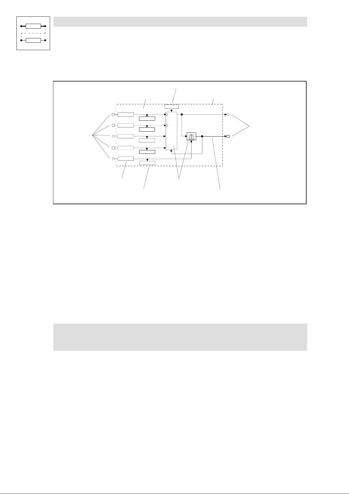
3.1.2 Elements of a function block
Input name
Parameterisation code
FB name
FCNT1−CLKUP
C1102/1
C1102/2
Input symbol
Configuration code
Fig. 3−1 Structure of a function block (FB) using the example of FCNT1
C1101/1
C1102/3
C1101/2
C1104/1
FCNT1−CLKDWN
C1104/2
FCNT1−LD−VAL
C1103/1
FCNT1−LOAD
C1104/3
FCNT1−CMP−VAL
C1103/2
Display code
C1100
CTRL
Function
FB name
Clearly identifies the FB. The FB name is followed by a number distinguishing the function of the FB.
Each FB is defined via its selection number. For calculating the FB the input of the selection number
into the processing table is always required. ( 3−12)
The selection numbers are listed in selection list 5.
Example:
FCNT1
FCNT1−OUT
Output symbol
FCNT1−EQUAL
Output name
(FCNT1, see Fig. 3−1)
l FCNT1 ¢ selection number 6400 (selection list 5).
Input symbol
Indicates the signal type which can be used as a signal source for this input. ( 3−5)
) Note!
Only inputs led through the FB can be configured.
Input name
Consists of the FB name and a designation. Inputs with the same function are distinguished by the
number that is added to the designation.
3−6
EDSVS9332P−EXT DE 2.0
l
Page 35

Function library
Working with function blocks
3.1.2 Elements of a function block
Configuration code
Configures the input with a signal source (e. g. terminal signal, control code, output of an FB, ...).
Inputs with identical codes are distinguished by the attached subcode (Cxxxx/1). These codes are
configured via the subcode.
It is not possible to connect an input with several signal sources.
Display code
Displays the current input value. Inputs with identical codes are distinguished by the attached
subcode (Cxxxx/1). These codes are displayed via the subcode.
Display codes cannot be processed.
Function
Represents the mathematical function as a block diagram (see Fig. 3−1).
Parameterisation code
Adaptation of the function or behaviour to the drive task. Possible settings are described in the text
editor and / or the line diagrams. ( 3−95)
Output symbol
Designates the signal type. Connections with inputs of the same signal type are possible. ( 3−5)
Each output is defined by a selection number. The selection numbers are divided into selection lists
(1 ... 4) according to the different signal types.
An output is linked to an input by the selection numbers.
Example:
(FCNT1, see Fig. 3−1)
l FCNT1−OUT ¢ selection number 6400 (analog signal, selection list 1).
l FCNT1−EQUAL ¢ selection number 6400 (digital signal, selection list 2).
) Note!
Only outputs brought out of the FB can be configured.
Output name
Consists of the FB name and a designation. Outputs with the same function are distinguished by the
number that is added to the designation.
l
EDSVS9332P−EXT DE 2.0
3−7
Page 36
Function library
Working with function blocks
3.1.3 Connecting function blocks
3.1.3 Connecting function blocks
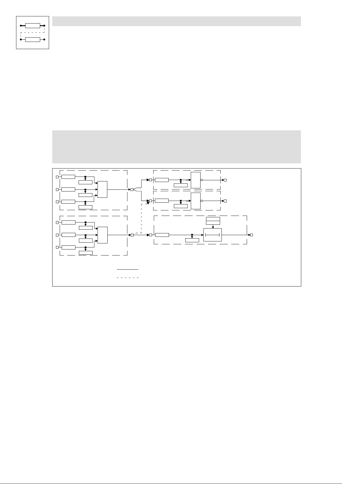
General rules
l Assign a signal source to an input.
l One input can have only one signal source.
l Inputs of different function blocks can have the same signal source.
l Only signals of the same type can be connected.
( Stop!
Existing connections which are not required must be removed by reconfiguration.
Otherwise the drive cannot perform the desired function.
&
|1
AND1
AND1−OUT
OR1
OR1−OUT
C0820/1
C0820/2
C0820/3
C0830/1
C0830/2
C0830/3
AND1−IN1
C0821/1
AND1−IN2
C0821/2
AND1−IN3
C0821/3
OR1−IN1
C0831/1
OR1−IN2
C0831/2
OR1−IN3
C0831/3
Fig. 3−2 Correct connection of function blocks
NOT1−IN
C0840
C0842
C0841
NOT2−IN
C0843
X
C0723
Connection is possible
Connection not possible
DIGDEL1−IN
C0724
1
1
NOT1
NOT1−OUT
NOT2
NOT2−OUT
C0720
C0721
0
DIGDEL1
DIGDEL1−OUT
t
3−8
EDSVS9332P−EXT DE 2.0
l
Page 37
Function library
Working with function blocks
3.1.3 Connecting function blocks
Basic procedure
1. Select the configuration code of the function block input which is to be changed.
2. Determine the source of the input signal for the selected input
(e.g. from the output of another function block).
3. The function block input is assigned via a menu which contains only those signal sources
which are of the same type as the function block input to be assigned.
4. Select and confirm the signal source.
5. Remove undesired connections, if any.
– For this, select the corresponding signal assignment of the input via the configuration code
(e.g. FIXED0, FIXED1, FIXED0%, ...).
6. Repeat 1. to 5. until the desired configuration is set.
7. Save modified configuration in the desired parameter set.
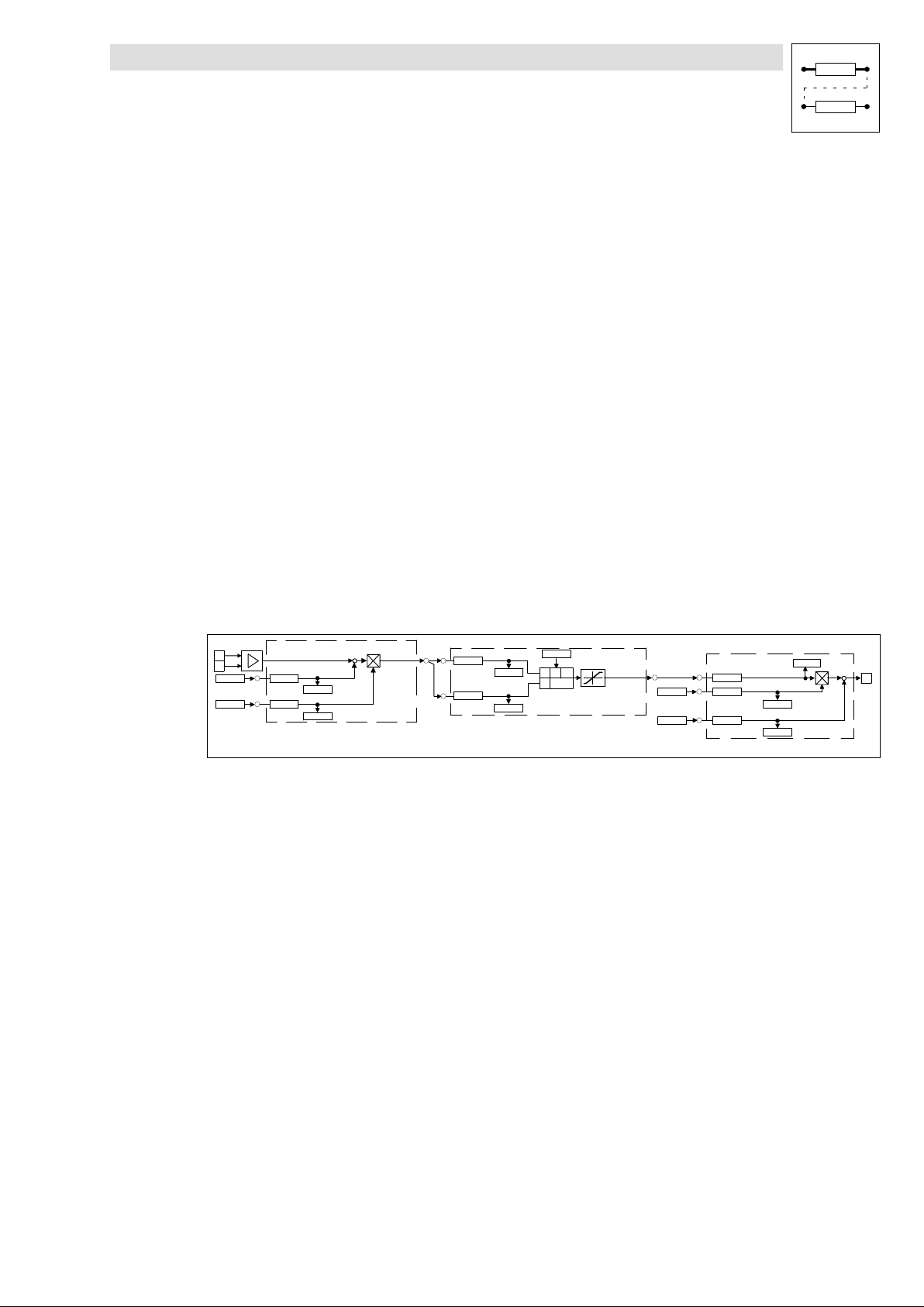
Example
l Condition:
– Default setting
l Task:
– Square the analog signal of X6/3, X6/4 and output to X6/62.
l Solution:
– You need the function blocks AIN2, ARIT2 and AOUT2.
3
4
C0026/2
C0027/2
C0407
C0408
AIN2−OFFSET
AIN2−GAIN
C0409/1
C0409/2
+
+
Fig. 3−3 Example of a simple configuration
AIN2
AIN2−OUT
C0601/1
C0601/2
ARIT2−IN1
C0602/1
ARIT2−IN2
C0602/2
C0600
x
−
+
*
y
x/(1−y)
/
"200%
ARIT2
ARIT2−OUT
C0108/1
C0109/1
C0431
C0433
C0432
C434/1
AOUT1−IN
AOUT1−GAIN
C0434/3
AOUT1−OFFSET
C0434/2
AOUT1
+
62
+
l
EDSVS9332P−EXT DE 2.0
3−9
Page 38

Function library
Working with function blocks
3.1.3 Connecting function blocks
Create connections
1. Determine the signal source for ARIT2−IN1:
– Change to the code level using the arrow keys
– Select C0601/1 using or .
– Change to the parameter level using PRG.
– Select output AIN2−OUT (selection number 55) using or .
– Confirm using SH + PRG
– Change to the code level again using PRG.
2. Determine signal source for ARIT2−IN2:
– Select C0601/2 using .
– Change to the parameter level using PRG.
– Select output AIN2−OUT (selection number 55) using or .
– Confirm using SH + PRG
– Change to the code level again using PRG.
3. Parameterise ARIT2:
– Select C0600 using .
– Change to the parameter level using PRG.
– Select multiplication (selection number 3).
– Confirm using SH + PRG
– Change to the code level again using PRG.
4. Determine signal source for AOUT1:
– Select C0431 using .
– Change to the parameter level using PRG.
– Select output ARIT2−OUT (selection number 5505).
– Confirm using SH + PRG
– Change to the code level again using PRG.
5. Enter function block ARIT2 in the processing table:
– Select C0465 and subcode 8 using .
– Change to the parameter level using PRG.
– Enter function block ARIT2 (selection number 5505).
– Confirm using SH + PRG
– Change to the code level again using PRG.
– The sequence of the FB processing is thus determined.
3−10
EDSVS9332P−EXT DE 2.0
l
Page 39
Function library
Working with function blocks
3.1.3 Connecting function blocks
Remove connections
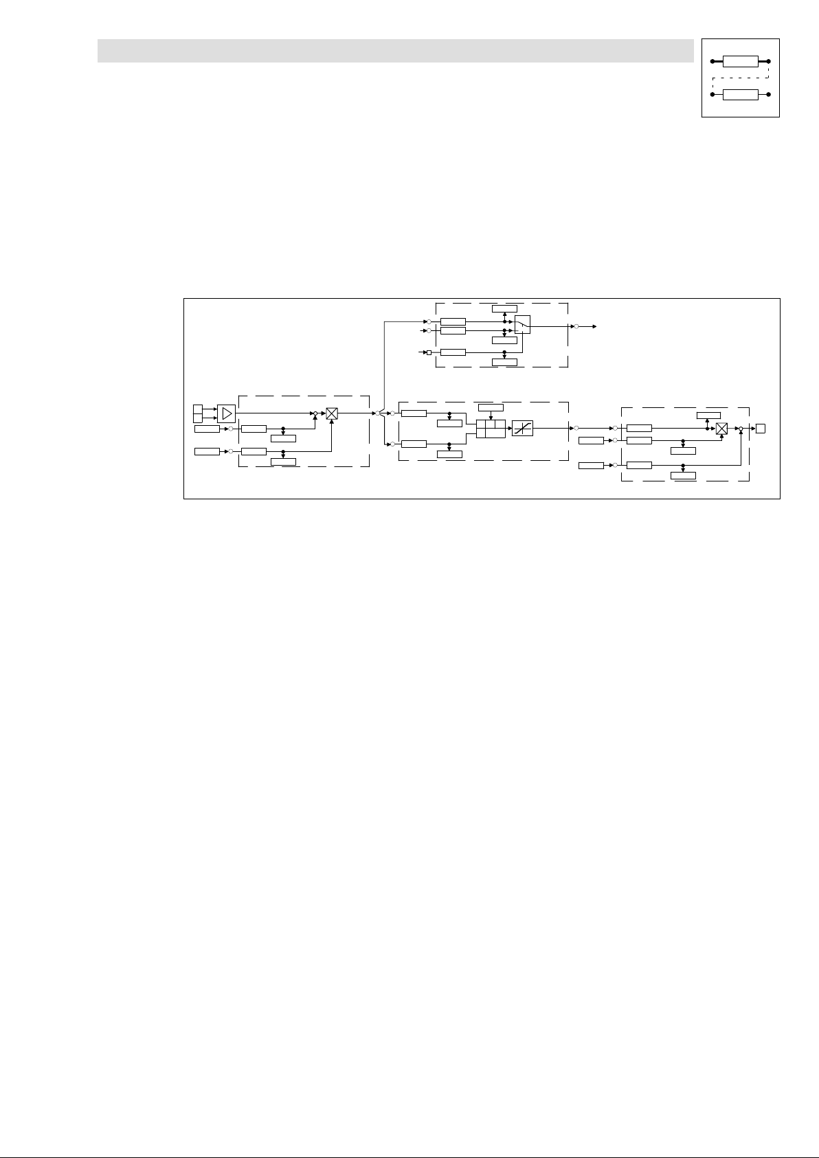
l Since a source can have several targets, there may be additional, unwanted signal
connections.
l Example:
– In the basic configuration C0005 = 1000, ASW1−IN1 and AIN2−OUT are connected.
– This connection is not automatically removed by the settings described above! If you do not
want this connection, remove it.
3
4
C0026/2
C0027/2
C0407
C0408
AIN2−OFFSET
C0409/1
AIN2−GAIN
C0409/2
+
AIN2
AIN2−OUT
+
Fig. 3−4 Removing connections in a configuration
1. Remove connection between ASW1−IN1 and AIN2−OUT:
– Select C0810/1 using or .
– Change to the parameter level using PRG.
– Select the constant FIXED0% (selection number 1000) using or .
– Confirm using SH + PRG
– Change to the code level again using PRG.
Now, the connection is removed.
2. Save new configuration, if desired:
– If you do not want to lose the modifications after mains disconnection, save the new signal
configuration under C0003 in one of the parameter sets.
FIXED0%
FIXED0
C0601/1
C0601/2
C0810/1
C0810/2
C0811
ARIT2−IN1
C0602/1
ARIT2−IN2
C0602/2
ASW1−IN1
ASW1−IN2
ASW1−SET
C0600
x
+
y
/
−
x/(1−y)
C0812/1
C0812/2
C0813
*
0
1
"200%
ASW1
ASW1−OUT
ARIT2
ARIT2−OUT
C0108/1
C0109/1
NSET−NADD
C0431
C0433
C0432
C434/1
AOUT1−IN
AOUT1−GAIN
C0434/3
AOUT1−OFFSET
C0434/2
AOUT1
+
62
+
l
EDSVS9332P−EXT DE 2.0
3−11
Page 40
Function library
Working with function blocks
3.1.4 Entries into the processing table
3.1.4 Entries into the processing table
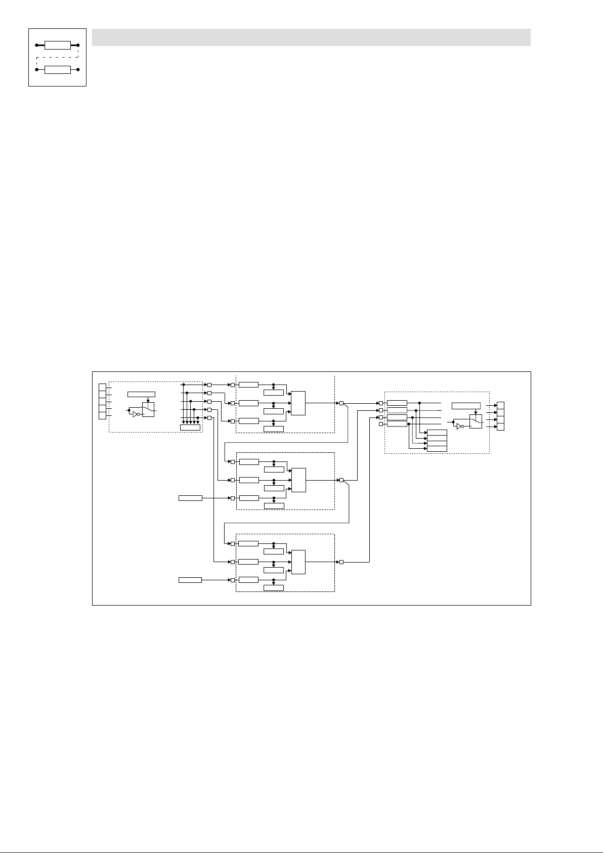
The 93XX drive controller provides a certain computing time for processing function blocks. Since
the type and number of the function blocks used can vary considerably, not all function blocks
available are permanently calculated. Therefore the code C0465 provides a processing table, in
which only the FBs used are entered. This means that the drive system is perfectly adapted to the
task to be solved. If further FBs are used in an extant configuration, they must be entered into the
processing table.
The following aspects must be observed:
The number of FBs to be processed is limited
A maximum of 50 FBs can be integrated into a configuration. Each FB needs a certain processing
time (operating time). The code C0466 shows the time still remaining for processing the FBs. If this
time has elapsed, no further FBs can be integrated.
Sequence for entering FBs
Normally, the sequence of the entries into C0465 is discretionary, but it may be important for
applications with a highly dynamic response. In general the most favourable sequence is adapted
to the signal flow.
Example:
DIGIN1
E1
E2
E3
E4
E5
DIGIN
C0114/1...5
0
1
DIGIN2
DIGIN3
DIGIN4
DIGIN5
Fig. 3−5 Example of a configuration
C0443
FIXED0
FIXED1
C0820/1
C0820/2
C0820/3
C0830/1
C0830/2
C0830/3
C0822/1
C0822/2
C0822/3
AND1-IN1
C0821/1
AND1-IN2
C0821/2
AND1-IN3
C0821/3
OR1-IN1
C0831/1
OR1-IN2
C0831/2
OR1-IN3
C0831/3
AND2-IN1
C0823/1
AND2-IN2
C0823/2
AND2-IN3
C0823/3
&
≥1
&
AND1
AND1-OUT
OR1
OR1-OUT
AND2
AND2-OUT
C0117/1
C0117/2
C0117/3
C0117/4
DIGOUT1
DIGOUT2
DIGOUT3
DIGOUT4
C0444/1
C0444/2
C0444/3
C0444/4
DIGOUT
C0118/1...4
0
1
A1
A2
A3
A4
3−12
EDSVS9332P−EXT DE 2.0
l
Page 41

Function library
Working with function blocks
3.1.4 Entries into the processing table
Structure of the processing table for the configuration example Fig. 3−5:
1. DIGIN does not have to be entered into the processing table.
2. The first FB is AND1, since it receives its input signals from DIGIN and only has successors.
3. The second FB is OR1, since its signal source is the output of AND1 (predecessor). Hence, the
output signal in AND1 must be generated first, before being processed in OR1. At the same
time, OR1 has a successor. Hence, OR1 must be entered into the processing table before the
successor.
4. The third FB is AND2, since it has a predecessor (see 3.)
5. The entries under C0465 are as follows:
– Position 10: AND1 10500
– Position 11: OR1 10550
– Position 12: AND2 10505
This example was started with position 10, since these positions are not assigned in the default
setting.
FBs do not have to be entered into the processing table directly one after the other. Empty positions
in the processing table are permissible.
) Note!
It is also possible that other FBs are entered between the FBs listed in the example.
FBs, which do not have to be entered into the processing table
The following signal sources are always executed and therefore do not need to be entered into the
processing table:
l AIF−IN
l CANx−IN
l DIGIN
l DIGOUT
l FCODE (all free codes)
l MCTRL
l fixed signal sources (FIXED0, FIXED0%, etc.)
Frequent errors
Malfunction Cause Remedy
FB does not supply an output signal FB was not entered into the processing table
FB only supplies constant signals FB was deleted from or overwritten in the
The output signal does not arrive at the
following FB
FB cannot be entered into the table C0465 Residual processing time is too short
The drive controller transmits internally
calculated signals with a delay to the outputs.
C0465
processing table C0465
The connection between the FBs has not been
established
(see C0466)
The FBs are processed in an incorrect
sequence
Enter FB
Enter FB again, possibly under a different
subcode (list position)
Establish the connection (from the view of the
following FB) via the configuration code (CFG)
Delete unused FBs (e. g. inputs and outputs
not used)
In networked drives, functions may be
assigned to other controllers
Adapt the processing table under C0465 to the
signal flow
l
EDSVS9332P−EXT DE 2.0
3−13
Page 42
Function library
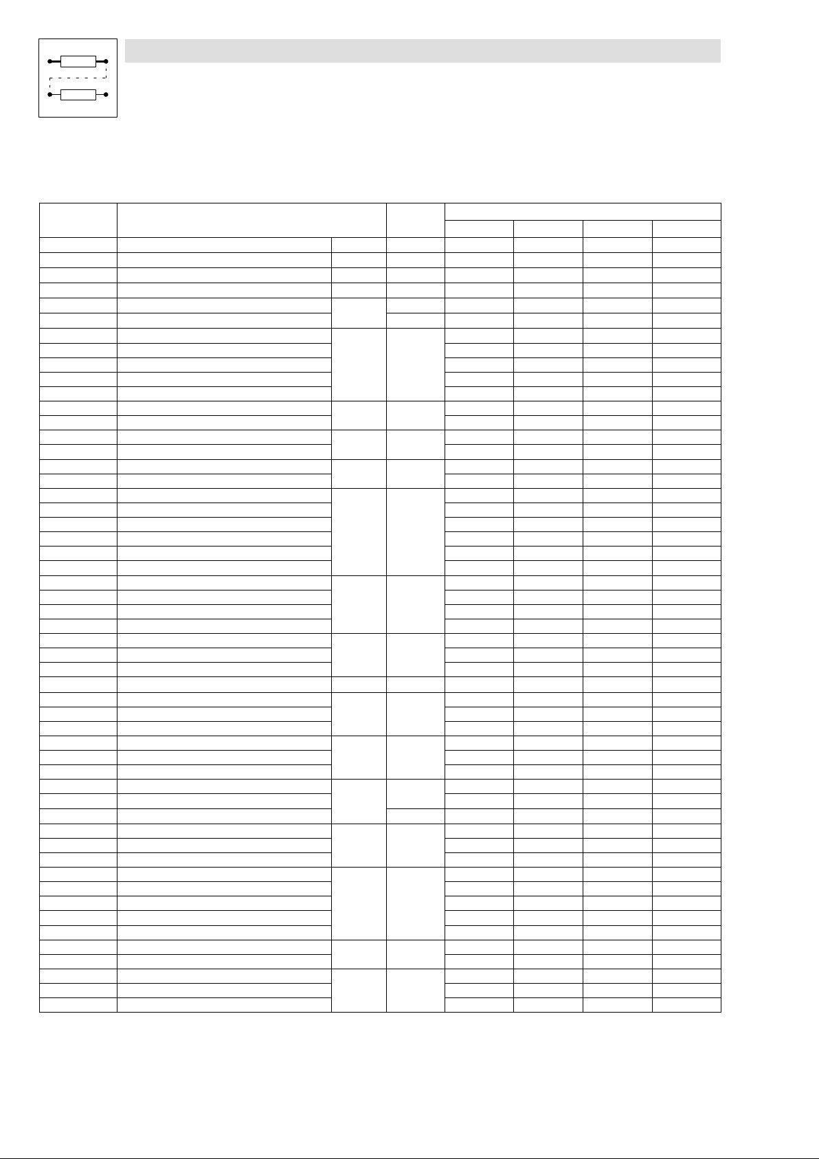
Table of function blocks
3.2 Table of function blocks
Function block Description CPU time
[ms]
ABS1 Absolute value generator 3−95 4
ADD1 Addition block 3−96 8
AIF−IN Fieldbus 3−97 60
AIF−OUT Fieldbus 3−100 56 ·
AIN1 Analog input X6/1, X6/2 3−102 10 ·
AIN2 Analog input X6/3, X6/4 28 ·
AND1 Logic AND, block1 3−104
AND2 Logic AND, block2
AND3 Logic AND, block3
AND4 Logic AND, block4
AND5 Logic AND, block5
ANEG1 Analog inverter 1 3−107
ANEG2 Analog inverter 2
AOUT1 Analog output X6/62 3−108
AOUT2 Analog output X6/63 · · · ·
ARIT1 Arithmetic block 1 3−110
ARIT2 Arithmetic block 2
ARITPH1 32−bit arithmetic block 3−111
ARITPH2 32−bit arithmetic block 2
ARITPH3 32−bit arithmetic block3
ARITPH4 32−bit arithmetic block 4
ARITPH5 32−bit arithmetic block 5
ARITPH6 32−bit arithmetic block 6
ASW1 Analog change−over switch 1 3−114
ASW2 Analog change−over switch 2
ASW3 Analog change−over switch 3
ASW4 Analog change−over switch 4
BCD1 BCD decade switch 1 3−116
BCD2 BCD decade switch 2
BCD3 BCD decade switch 3
BRK Holding brake control 3−127 15
CAN−IN1 System bus 3−132
CAN−IN2 System bus
CAN−IN3 System bus
CAN−OUT1 System bus 3−133
CAN−OUT2 System bus · · ·
CAN−OUT3 System bus · · ·
CMP1 Comparator 1 3−134
CMP2 Comparator 2
CMP3 Comparator 3 15
CMPPH1 Comparator 1 3−139
CMPPH2 Comparator 2
CMPPH3 Comparator 3
CONV1 Conversion of analog signals 3−144
CONV2 Conversion of analog signals
CONV3 Conversion of speed signals to analog signals
CONV4 Conversion of speed signals to analog signals
CONV5 Conversion of analog signals to speed signals
CONVAD1 Analog−digital converter 1 3−146
CONVAD2 Analog−digital converter 2
CONVAPH1 Analog phase converter 1 3−148
CONVAPH2 Analog phase converter 2
CONVAPH3 Analog phase converter 3
Used in basic configuration
1000 20000 22000 26000
6
3
12
11
15
4
30
−
56
15
20
8
4
31
· · · ·
· · · ·
·
· · ·
·
3−14
EDSVS9332P−EXT DE 2.0
l
Page 43
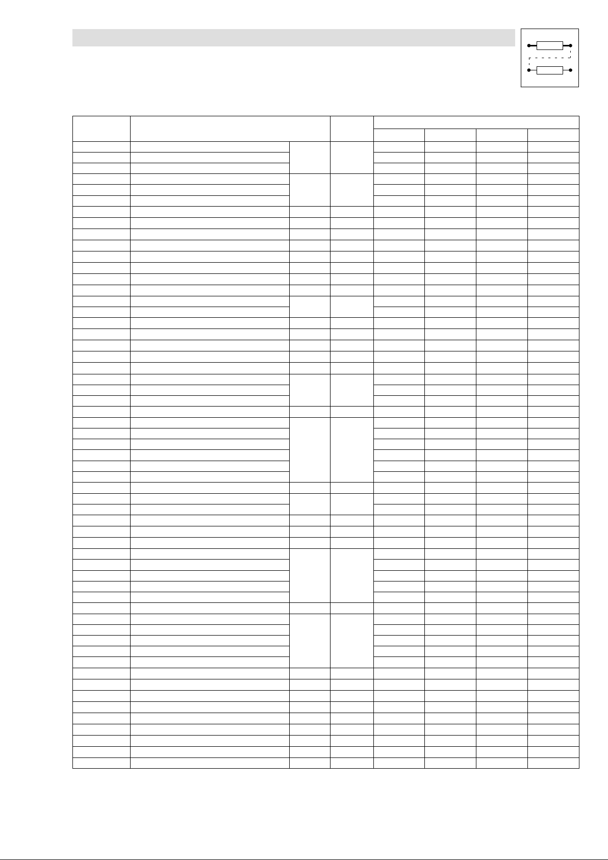
Function library
Table of function blocks
Function block Used in basic configurationCPU time
CONVDA1 Digital−analog converter 1 3−150
CONVDA2 Digital−analog converter 2
CONVDA3 Digital−analog converter 3
CONVPHA1 Phase analog converter 1 3−153
CONVPHA2 Phase analog converter 2
CONVPHA3 Phase analog converter 3
CONVPHPH2 Phase converter 2 3−155 80 ·
CURVE1 Characteristic function 3−156 15 ·
DB1 Dead band 3−159 7
DCTRL Device control 3−160 −
DFIN Digital frequency input 3−164 5 ·
DFOUT Digital frequency output 3−167 35 · · · ·
DFRFG1 Digital frequency ramp function generator 3−171 40
DFSET Digital frequency processing 3−177 85
DIGDEL1 Binary delay element 1 3−182
DIGDEL2 Binary delay element 2
DIGIN Input terminals X5/E1…X5/E5 3−185 −
DIGOUT Output terminals X5/A1…X5/A4 3−186 −
DISA Free analog display code 3−187 1
DISPH Free phase display code 3−189 1
DT1 Differential element 3−190 12
FCNT1 Free piece counter, block 1 3−191
FCNT2 Free piece counter, block 2
FCNT3 Free piece counter, block 3
FDO Free digital outputs 3−193 −
FEVAN1 Free analog input variable 3−195
FEVAN2 Free analog input variable
FEVAN3 Free analog input variable
FEVAN4 Free analog input variable
FEVAN5 Free analog input variable
FEVAN6 Free analog input variable
FIXSET1 Fixed setpoints 3−202 9
FLIP1 D−flipflop 1 3−204
FLIP2 D−flipflop 2
LIM1 Limiter 3−207 5
MCTRL Servo control 3−208 −
MPOT1 Motor potentiometer 3−220 20
NOT1 Logic NOT, block1 3−223
NOT2 Logic NOT, block2 ·
NOT3 Logic NOT, block3 ·
NOT4 Logic NOT, block4
NOT5 Logic NOT, block5
NSET Speed setpoint conditioning 3−225 70 ·
OR1 Logic OR, block1 3−230
OR2 Logic OR, block2 ·
OR3 Logic OR, block3
OR4 Logic OR, block4
OR5 Logic OR, block5
OSC Oscilloscope function 3−233 70
PCTRL1 Process controller 3−237 58
PHDIV1 Conversion 3−240 8
PHINT1 Phase integrator 3−241 7
POS Positioning control 3−19 330 · · ·
PT1−1 1st order delay element 3−244 8
R/L/Q QSP / setpoint inversion 3−245 8 ·
RFG1 Ramp function generator 3−246 16
S&H1 Sample and Hold 3−248 4
DescriptionFunction block
Description
CPU time
[ms]
[ms]
38
6
9
11
4
6
4
6
2600022000200001000
· · ·
·
l
EDSVS9332P−EXT DE 2.0
3−15
Page 44
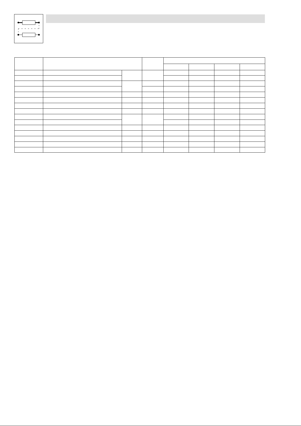
Function library
Table of function blocks
Function block Used in basic configurationCPU time
SELPH1 Phase value selection, block 1 3−249
SELPH2 Phase value selection, block 2
SP1 Position switch points, block 1 3−251 80 ·
SP2 Position switch points, block 2 130
STAT Output of digital status signals 3−258 −
STATE−BUS Control of a drive network 3−259 −
SYNC1 Multi−axis positioning 3−260 37 ·
TEACH1 Teach in programming 3−268 10 ·
TRANS1 Binary edge evaluation 3−270
TRANS2 Binary edge evaluation
VTACC "Acceleration" variable table 3−273 20
VTPCS "Piece number" variable table 3−275 12
VTPOS "Target position" variable table 3−277 45
VTTIME "Waiting time" variable table 3−279 12
VTVEL "Speed" variable table 3−281 18
DescriptionFunction block
Description
CPU time
[ms]
[ms]
6
7
2600022000200001000
·
3−16
EDSVS9332P−EXT DE 2.0
l
Page 45

3.3 Table of free control codes
Free control codes can be used for the selection of setpoints or as variables. The codes can be
connected with inputs of function blocks.
Function library
Table of control codes
Designation Signal type Code Connection to the function block in
the Lenze setting
FCODE−17 a C0017 −
FCODE−26/1 a C0026/1 AIN1−OFFSET
FCODE−26/2 a C0026/2 AIN2−OFFSET
FCODE−27/1 a C0027/1 AIN1−GAIN
FCODE−27/2 a C0027/2 AIN2−GAIN
FCODE−32 a C0032 −
FCODE−37 a C0037 −
FCODE−108/1 a C0108/1 AOUT1−GAIN
FCODE−108/2 a C0108/2 AOUT2−GAIN
FCODE−109/1 a C0109/1 AOUT1−OFFSET
FCODE−109/2 a C0109/2 AOUT2−OFFSET
FCODE−141 a C0141 −
FCODE−1211 a C1211 POS−START−PS
FCODE−472/1 a C0472/1 −
FCODE−472/2 a C0472/2 −
FCODE−472/3 a C0472/3 ANEG1−IN
MCTRL−HI−M−LIM
FCODE−472/4 a C0472/4 −
FCODE−472/5 a C0472/5 −
FCODE−472/6 a C0472/6 MCTRL−PHI−LIM
FCODE−472/7 a C0472/7 −
FCODE−472/8 a C0472/8 −
FCODE−472/9 a C0472/9 −
FCODE−472/10 a C0472/10 −
FCODE−472/11 a C0472/11 −
FCODE−472/12 a C0472/12 −
FCODE−472/13 a C0472/13 −
FCODE−472/14 a C0472/14 −
FCODE−472/15 a C0472/15 −
FCODE−472/16 a C0472/16 −
FCODE−472/17 a C0472/17 −
FCODE−472/18 a C0472/18 −
FCODE−472/19 a C0472/19 −
FCODE−472/20 a C0472/20 −
FCODE−473/1 a C0473/1 −
FCODE−473/2 a C0473/2 −
FCODE−473/3 a C0473/3 −
FCODE−473/4 a C0473/4 −
FCODE−473/5 a C0473/5 −
FCODE−473/6 a C0473/6 −
FCODE−473/7 a C0473/7 −
FCODE−473/8 a C0473/8 −
FCODE−473/9 a C0473/9 −
FCODE−473/10 a C0473/10 −
FCODE−250 d C0250 −
FCODE−471.B0 d C0471 −
FCODE−471.B1 d C0471 POS−S−RAMPS
FCODE−471.B2 d C0471 −
FCODE−471.B3 d C0471 −
Note
l
EDSVS9332P−EXT DE 2.0
3−17
Page 46

Function library
Table of control codes
Designation NoteConnection to the function block in
FCODE−471.B4 d C0471 −
FCODE−471.B5 d C0471 −
FCODE−471.B6 d C0471 −
FCODE−471.B7 d C0471 −
FCODE−471.B8 d C0471 −
FCODE−471.B9 d C0471 −
FCODE−471.B10 d C0471 −
FCODE−471.B11 d C0471 −
FCODE−471.B12 d C0471 −
FCODE−471.B13 d C0471 −
FCODE−471.B14 d C0471 −
FCODE−471.B15 d C0471 −
FCODE−471.B16 d C0471 −
FCODE−471.B17 d C0471 −
FCODE−471.B18 d C0471 −
FCODE−471.B19 d C0471 −
FCODE−471.B20 d C0471 −
FCODE−471.B21 d C0471 −
FCODE−471.B22 d C0471 −
FCODE−471.B23 d C0471 −
FCODE−471.B24 d C0471 −
FCODE−471.B25 d C0471 −
FCODE−471.B26 d C0471 −
FCODE−471.B27 d C0471 −
FCODE−471.B28 d C0471 −
FCODE−471.B29 d C0471 −
FCODE−471.B30 d C0471 −
FCODE−471.B31 d C0471 −
FCODE−135.B0 d C0135 − LECOM control word
FCODE−135.B1 d C0135 − LECOM control word
FCODE−135.B2 d C0135 − LECOM control word
FCODE−135.B3 d C0135 − LECOM control word, signal: QSP (see DCTRL)
FCODE−135.B4 d C0135 − LECOM control word
FCODE−135.B5 d C0135 − LECOM control word
FCODE−135.B6 d C0135 − LECOM control word
FCODE−135.B7 d C0135 − LECOM control word
FCODE−135.B12 d C0135 − LECOM control word
FCODE−135.B13 d C0135 − LECOM control word
FCODE−135.B14 d C0135 − LECOM control word
FCODE−135.B15 d C0135 − LECOM control word
FCODE−474/1 ph C0474/1 −
FCODE−474/2 ph C0474/2 −
FCODE−474/3 ph C0474/3 −
FCODE−474/4 ph C0474/4 −
FCODE−474/5 ph C0474/5 −
FCODE−474/6 ph C0474/6 −
FCODE−474/7 ph C0474/7 −
FCODE−474/8 ph C0474/8 −
FCODE−474/9 ph C0474/9 −
FCODE−474/10 ph C0474/10 −
FCODE−475/1 phd C0475/1 −
FCODE−475/2 phd C0475/2 −
CodeSignal type
the Lenze setting
3−18
EDSVS9332P−EXT DE 2.0
l
Page 47
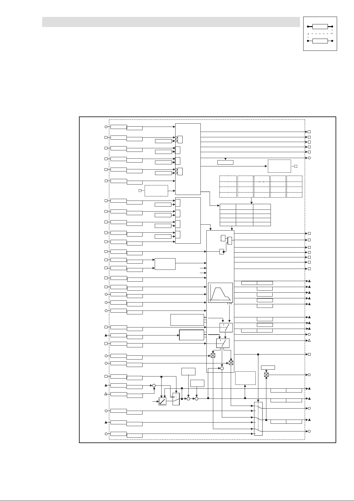
3.4 Positioning control (POS)
Purpose
The function block "positioning control (POS)" is the core of the 9300 servo position controller. It
controls positioning in the controller.
Function library
Positioning control
P O S - S T A R T - P S
C 1 3 6 2 / 1
C 1 3 6 3 / 1
P O S - P R G - S T A R T
C 1 3 6 0 / 1
C 1 3 6 1 / 1
P O S - P R G - S T O P
C 1 3 6 0 / 2
C 1 3 6 1 / 2
P O S - P R G - R E S E T
C 1 3 6 0 / 3
C 1 3 6 1 / 3
P O S - P S - C A N C E L
C 1 3 6 0 / 1 5
C 1 3 6 1 / 1 5
P O S - S T D B Y - S T P
C 1 3 6 0 / 1 6
C 1 3 6 1 / 1 6
P O S - M A N U A L
C 1 3 6 0 / 6
C 1 3 6 1 / 6
P O S - M A N U - N E G
C 1 3 6 0 / 7
C 1 3 6 1 / 7
P O S - M A N U - P O S
C 1 3 6 0 / 8
C 1 3 6 1 / 8
P O S - M A N U - R E F
C 1 3 6 0 / 9
C 1 3 6 1 / 9
P O S - R E F - M A R K
C 1 3 6 0 / 1 0
C 1 3 6 1 / 1 0
P O S - W A I T S T A T E
C 1 3 6 0 / 2 2
C 1 3 6 1 / 2 2
P O S - L I M - N E G
C 1 3 6 0 / 4
C 1 3 6 1 / 4
P O S - L I M - P O S
C 1 3 6 0 / 5
C 1 3 6 1 / 5
P O S - P A R A M - R D
C 1 3 6 0 / 1 8
C 1 3 6 1 / 1 8
P O S - S - R A M P S
C 1 3 6 0 / 1 7
C 1 3 6 1 / 1 7
P O S - J E R K - R E D
C 1 3 6 2 / 8
C 1 3 6 3 / 8
P O S -V- O V E R R I D
C 1 3 6 2 / 2
C 1 3 6 3 / 2
P O S -A- O V E R R I D
C 1 3 6 2 / 3
C 1 3 6 3 / 3
P O S - L O O P - I N H
C 1 3 6 0 / 1 9
C 1 3 6 1 / 1 9
P O S - P S E T - E X T
C 1 3 6 4 / 1
C 1 3 6 5 / 1
P O S - P S E T - S W T
C 1 3 6 0 / 2 0
C 1 3 6 1 / 2 0
P O S - M O U T - G A I N
C 1 3 6 2 / 7
C 1 3 6 3 / 7
P O S - N O U T - G A I N
C 1 3 6 2 / 5
C 1 3 6 3 / 5
P O S - A B S - S E T
C 1 3 6 0 / 2 1
C 1 3 6 1 / 2 1
P O S - A B S - I N
C 1 3 6 4 / 2
C 1 3 6 5 / 2
P O S - P H I - A D D
C 1 3 6 6 / 1
C 1 3 6 7 / 1
M C T R L - P H I - A C T
( f e e d b a c k s e l e c t e d u n d e r C 4 9 0 )
P O S - N - I N
C 1 3 6 2 / 4
C 1 3 6 3 / 4
P O S - P - I N
C 1 3 6 4 / 3
C 1 3 6 5 / 3
P O S - M - I N
C 1 3 6 2 / 6
C 1 3 6 3 / 6
P R G - C T R L
1
C 1 2 8 0 . B 0
C 1 2 8 0 . B 1
C 1 2 8 0 . B 2
C 1 2 8 0 . B 3
³
1
³
1
³
1
³
P O S - P F I
1
C 1 2 8 0 . B 4
C 1 2 8 0 . B 5
C 1 2 8 0 . B 6
C 1 2 8 0 . B 7
L I M - C T R L
( f r o m p a t h c o n t r o l u n i t )
+
+
S e t
( E x t e r n a l s e t v a l u e s f o r s t a n d - b y o p
³
1
³
M A N U A L
H O M I N G
1
³
1
³
D C T R L -
M C T R L -
Q S P
S E T P O S = A C T P O S
S E T P O S - E X T
( I n f l u e n c e o f f e e d f o r w a r d v a l u e s )
h o m e p o s i t i o n
C 1 2 2 7
C 1 2 2 1 / 8
1
0
( G e n e r a t i o n o f a c t u a l p o s i t i o n )
+
C T R L
C I N H
- O U T
V S E T = 0
A S E T = 0
V S E T - E X T
A S E T - E X T
h o m e o f f s e t
C 1 2 2 5
C 1 2 2 1 / 7
+++
-
e r a t i o n )
C 1 2 1 2
V a r i a b l e t a b l e s ( V T )
V T P O S
C 1 3 0 1 / 1
C 1 3 0 1 / 1 0 4
P r o g r a m s e t s ( P S )
C 1 3 1 1 / 1
C 1 3 1 2 / 1
C 1 3 4 9 / 1
S E T P O S
=
T A R G E T
S p e e d p r o f i l e r
1 0
1 0
-
( F o l l o w i n g e r r o r )
( T o r q u e )
V T V E L
C 1 3 0 2 / 1
. . .
C 1 3 0 2 / 3 4
. . .
P S 1
. . .
. . .
. . . . . .
. . .
&
( L a t c h e d p r o f i l e v a l u e s )
( V a l u e s f o l l o w i n g t h e p r o f i l e )
( V i r t u a l m a s t e r f u n c t i o n )
+
P O S - T P
( T o u c h P r o b e )
( S p e e d )
. . .
C 1 2 2 0 / 1
C 1 2 2 0 / 2
V T A C C
C 1 3 0 3 / 1
. . .
C 1 3 0 3 / 3 4
P S 3 2
C 1 3 1 1 / 3 2
C 1 3 1 2 / 3 2
. . .
C 1 3 4 9 / 3 2
C 1 2 2 1 / 1
C 1 2 4 5 / 2
C 1 2 4 5 / 3
C 1 2 5 5 / 2
C 1 2 5 5 / 3
C 1 2 5 5 / 1
C 1 2 4 5 / 1
C 1 2 2 1 / 2
( P 1 4 t o l e r a n c e )
C 1 2 1 8 / 1
0
1
0
1
0
1
P O S - R U N N I N G
P O S
P O S - S T A R T E D
P O S - S T O P P E D
P O S - E N D E D
P O S - R E S E T E D
P O S - A C T - P S - N O
P O S - P F O
V T T I M E
V T P C S
C 1 3 0 5 / 1
C 1 3 0 4 / 1
. . .
C 1 3 0 5 / 3 4
C 1 3 0 4 / 3 4
P O S - R E F - O K
P O S - I N - T A R G E T
P O S - V T R A V - R E A
P O S - V F I N - R E A C
P O S - A C C - R A M P
P O S - D C C - R A M P
P O S - M A N U - A C T
P O S - T A R G E T
P O S - V T R A V
P O S - V F I N A L
P O S - A C C
P O S - D C C
P O S - A S E T
P O S - V S E T
P O S - S E T P O S
P O S - N S E T
P O S - P H I - S E T
P O S - S T D B Y - A C T
P O S - P O U T - N O R M
P O S - A B S - V A L
C 1 2 2 1 / 1 6C 1 2 2 0 / 1 6
P O S - A C T P O S
C 1 2 2 1 / 3
C 1 2 2 0 / 3
P O S - N O U T
P O S - P O U T
C 1 2 2 1 / 4C 1 2 2 0 / 4
P O S - M O U T
. . .
9300POS001
Fig. 3−6 Function block POS
l
EDSVS9332P−EXT DE 2.0
3−19
Page 48

Function library
Positioning control
Signal Source Note
Designation Type DIS DIS format CFG List
POS−A−OVERRID a C1363/3 dec [%] C1362/3 1 Reduces the acceleration and deceleration as well as the manual traversing
POS−ABS−IN ph C1365/2 dec [inc] C1364/2 3 Input for external actual position value, e. g. when using an absolute value
POS−ABS−SET d C1361/21 bin C1360/21 2 HIGH = Phase value at POS−ABS−IN is read for generating the actual position value
POS−ABS−VAL ph C1220/16
C1221/16
POS−ACC ph C1255/2 dec [inc] − − Deceleration, absolute value for current PS; for scaling see formula 3.
POS−ACC−RAMP d − − − − HIGH = Drive accelerates
POS−ACT−PS−NO a C1212 dec [inc] − − Current program block
POS−ACTPOS ph C1220/3
C1221/3
POS−ASET ph C1255/1 dec [inc] − − Current acceleration/deceleration setpoint, for scaling see formula 3.
POS−DCC ph C1255/3 dec [inc] − − Deceleration in current program block (positive display); for scaling see formula 3
POS−DCC−RAMP d − − − − HIGH = drive brakes
POS−ENDED d − − − − Position status display
POS−IN−TARGET d − bin − − HIGH = Position setpoint has reached target position, positioning is completed, the
POS−JERK−RED a 1363/8 dec [%] C1362/8 1 Reduces the jerk of an S profile, or prolongs the jerk time (Tr)
POS−LIM−NEG d C1361/4 bin C1360/4 2 HIGH = negative end of travel range limit switch approached.
POS−LIM−POS d C1361/5 bin C1360/5 2 HIGH = positive travel range limit switch approached.
POS−LOOP−INH d C1361/19 bin C1360/19 2 HIGH = position control loop is switched off. (POS−SETPOS = POS−ACTPOS,
POS−M−IN a C1363/6 dec [%] C1362/6 1 External torque precontrol, effective in stand−by operation ( 3−81)
POS−MANU−ACT d − − − − HIGH = manual operation active, no program operation
POS−MANU−NEG d C1361/7 bin C1360/7 2 HIGH = drive travels with v_manual (C1243) in negative direction. Acceleration
POS−MANU−POS d C1361/8 bin C1360/8 2 like POS−MANU−NEG, but in positive direction. (see "Manual operation" 3−67)
POS−MANU−REF d C1361/9 bin C1360/9 2 LOW−HIGH signal = Start manual homing
POS−MANUAL d C1361/6 bin C1360/6 2 Changeover Manual/program operation
POS−MOUT a − − − − Current torque precontrol value after influence of POS−MOUT−GAIN. Scaling: 100%
dec [units]
dec [inc]
dec [units]
dec [inc]
− − Actual position; for scaling see formula 1
acceleration and homing acceleration.
Note: Only positive override values are effective, negative values will be evaluated
as zero. (See "Override" 3−62)
encoder with a CAN interface.
(see Absolute encoder via system bus" 3−40)
(POS−ACTPOS). The following values are considered for the POS−ACTPOS: position
setpoint polarity (C1206), actual position polarity (C1208), actual home position
(display C1220/8), actual dimension offset (display C1220/7).
Display as actual position POS−ACTPOS, but without considering setpoint position
polarity (C1206), actual position (C1206), actual home position (display C1220/8)
and actual reference dimension offset (display C1220/7).
HIGH = program end reached. Current program block no.=0 (POS−ACT−PS−NO).
(see program control" 3−70)
following function of the PS will be processed.
LOW = Positioning is running or was cancelled by POS−PS−CANCEL.
POS−IN−TARGET remains LOW, as long as POS−WAITESTATE = HIGH. 3−64
(see "S ramps" 3−60).
Note: will be evaluated as value.
(see Travel limits" 3−44)
(see Travel range limits" 3−44)
POS−VSET = 0, POS−ASET = 0).
Note: Signal will not be updated when the controller is inhibited (DCTRL−CINH =
HIGH) or quick stop (MCTRL−QSP−OUT = HIGH) is set
with a−manual (C1252). The override inputs POS−V−OVERRID and POS−A−OVERRID
have influence.
LOW = drive is stopped with a−manual (C1252). The override inputs
POS−V−OVERRID and POS−A−OVERRID have influence.
Note: POS−MANU−REF has priority. When −NEG and −POS are controlled
simultaneously the drive stops. (see "Manual operation" 3−67)
HIGH level required for the time of homing
(see manual homing" 3−69)
HIGH = manual operation; if necessary, running program is interrupted. If
necessary, drive is decelerated to standstill with a−manual (C1252) and the
influence of POS−A−OVERRID.
LOW = Program mode (see manual mode" 3−67)
acc. to a−max (C1250).
3−20
EDSVS9332P−EXT DE 2.0
l
Page 49

Function library
Positioning control
Signal NoteSource
Designation ListCFGDIS formatDISType
POS−MOUT−GAIN a C1363/7 dec [%] C1362/7 1 Reduces torque precontrol. The polarity of the input signal is considered.
POS−N−IN a C1363/4 dec [%] C1362/4 1 External speed setpoint, effective in stand−by operation ( 3−81)
POS−NOUT a − − − − Current speed setpoint for n controller after influence of POS−NOUT−GAIN. Scaling:
POS−NOUT−GAIN a C1363/5 dec [%] C1362/5 1 Reduces speed precontrol. The polarity of the input signal is considered.
POS−NSET a − − − − Current speed setpoint (profile generator output), scaling: 100% acc. to nmax
POS−P−IN ph C1365/3 dec [inc] C1364/3 3 Externally calculated following error, effective in stand−by operation ( 3−81)
POS−PARAM−RD d C1361/18 bin C1360/18 2 LOW−HIGH signal = new profile parameters will be accepted immediately, even
POS−PHI−ADD phd C1367/1 C1366/1 Phase difference signal is added to POS−ABS−IN.
POS−PHI−SET phd − − − − Virtual Master" application: 3−65)
POS−POUT ph − − − − Following error for phase controller
POS−POUT−NORM d − dec [%] Scaled analog following error output. The current following error POS−POUT is
POS−PRG−RESET d C1361/3 bin C1360/3 2 HIGH= interrupts the program processing and sets "program end". Parts counters
POS−PRG−START d C1361/1 bin C1360/1 2 Start of the program.
POS−PRG−STOP d C1361/2 bin C1360/2 2 HIGH = program processing and the running positioning are interrupted. The drive
POS−PS−CANCEL d C1361/15 bin C1360/15 2 Cancel PS and continue program from another point.
POS−PSET−EXT ph C1365/1 dec [inc] C1364/1 3 External position setpoint.
POS−PSET−SWT d C1361/20 bin C1360/20 2 HIGH = Phase value at POS−PSET−EXT will be accepted as position setpoint
POS−REF−MARK d C1361/10 bin C1360/10 2 Home position switch
POS−REF−OK d C1284/1 − − − HIGH = Homing completed/reference known
POS−RESETED d − − − − Position status display
100% acc. to. nmax (C0011).
(C0011).
during positioning
HIGH level accepts new parameters every 10 ms
Profile parameters: target position, traversing speed, acceleration, deceleration,
final speed, V−OVERRID, A−OVERRID, POS−S−RAMPS.
Note: Not effective in stand−by operation ("Stand−By operation" see 3−81)
Function: With POS−ABS−SET= HIGH the actual position is set to the value
POS−ABS−IN. Encoder increments that have arrived in the setting cycle are not
considered in the default. If required, the encoder change can be connected in the
setting cycle; the signal MCTRL−PHI−ACT must be linked with the input
POS−PHI−ADD.
additionally output as follows:
100% equals first following error tolerance (C1218/1).
Tip: for monitoring the dynamic drive response.
and PFOs are reset. The Touch Probe inputs used by the program are disabled
and, if required, the stand−by operation is interrupted. The drive is stopped with
a−max (C1250) (no influence of POS−A−OVERRID).
(see program control" 3−70)
LOW−HIGH edge = Start, from the beginning (POS−START−PS) or continued at the
same position after program interruption. The program is executed to the
"program end", even if POS−PRG−START is reset again.
If POS−PRG−START = HIGH at the program end, the program will be processed
again from its beginning.
(see program control" 3−70)
is stopped with the current delay of the program block (no influence of
POS−A−OVERRID).
LOW = Program processing is continued. Positioning is continued with the current
profile parameters of the program block, if required.
(see program control" 3−70)
LOW−HIGH edge = aborts current program block. Drive is braked to standstill with
the separately adjustable delay a−cancel" (C1253). Afterwards the program is
continued in the selected program block (C1333; JMP−TP−PS).
(see program control" 3−70)
(POS−SETPOS)
LOW = Position setpoint will be generated by the profile generator.
HIGH = Position program in status Prg−Reset"
(see program control" 3−70)
l
EDSVS9332P−EXT DE 2.0
3−21
Page 50

Function library
Positioning control
Signal NoteSource
Designation ListCFGDIS formatDISType
POS−RUNNING d − − − − Position status display
POS−S−RAMPS d C1361/17 bin C1361/17 2 HIGH level = S profile is active (see S−shaped ramps" 3−60)
POS−SETPOS ph C1220/2
C1221/2
POS−START−PS a C1363/1 dec [inc] C1362/1 1 Start program set
POS−STARTED d − − − − Position status display
POS−STDBY−ACT d − − − − HIGH = stand−by operation is active (see Stand−by operation" 3−81)
POS−STDBY−STP d C1361/16 bin C1360/16 2 HIGH = terminates the stand−by operation, if "STDBY" is selected in the POS mode
POS−STOPPED d − − − − Position status display
POS−TARGET ph C1220/1
C1221/1
POS−V−OVERRID a C1363/2 dec [%] C1362/2 1 Reduces the traversing and final speed as well as the manual traversing speed
POS−VFIN−REAC d − − − − HIGH = current final speed reached
POS−VFINAL ph C1245/3 dec [inc] − − Acceleration, absolute value for current PS, for scaling see formula 3.
POS−VSET ph C1245/1 dec [inc] − − Current speed setpoint; for scaling see formula 2
POS−VTRAV ph C1245/2 dec [inc] − − Final speed, absolute value for current PS, for scaling see formula 2.
POS−VTRAV−REA d − − − HIGH = current traversing speed reached
POS−WAITSTATE d C1360/22 bin C1361/22 2002 Completion of positioning in the actual program block is delayed to wait until the
dec [units]
dec [inc]
dec [units]
dec [inc]
− − Current position setpoint; for scaling see formula 1
− − current target position in real measuring system; for scaling see formula 1
POS−RUNNING = HIGH: Program run is started and is not interrupted by controller
inhibit, faults or manual control.
POS−RUNNING = LOW and POS−STARTED = HIGH: Program run interrupted; for
continuing the program run a new edge to POS−PRG−START is required.
Number of the program set with which the program run is to be started. In the
standard configurations (see C0005) it is connected with C1211,
HIGH = Program started
If the program has been interrupted by controller inhibit, fault or manual homing,
POS−STARTED remains HIGH. The program can only continue if a new signal is
applied to POS−PRG−START.
(see program control" 3−70)
(C1311 = 30). No other function. (see Stand−by operation" 3−81)
HIGH = Program and drive have been stopped or drive is being stopped
(see program control" 3−70)
and the homing speed.
Note: Only positive override values are effective, negative values will be evaluated
as zero. (See "Override" 3−62)
possibly occurring following error has been eliminated when reaching the target.
HIGH = POS−IN−TARGET is not set, the actual positioning is not completed.
(see chapter Target window" 3−64)
3−22
EDSVS9332P−EXT DE 2.0
l
Page 51
Function library
Positioning control
Formulae for scaling the signals (see preceding table, column "Note"):
Formula 1: Position
Position[inc] + Position[units] @
65536[incńrev.] @ gearnominator
Feedconst.[unitsńrev.] @ geardenominator
Formula 2: Speed (VEL)
VEL[incvńms] + VEL[unitsńs] @
65536[incńrev.] @ gearnominator @ 16384[inc
Feedconst.[unitsńrev.] @ geardenominator @ 1000[1ńs]
Formula 3: Acceleration/deceleration (ACC/DCC)
ACC[incvńms2] + ACC[unitsńs2] @
65536[incńrev.] @ gearnominator @ 16384[incvńinc]
Feedconst.[unitsńrev.] @ geardenominator @ 1000000[1ńs
+ Position @
ńinc]
v
65536 @ C1202
C1204 @ C1203
+ VEL @
+ ACC @
2
]
65536 @ C1202 @ 16384
C1204 @ C1203 @ 1000
65536 @ C1202 @ 16384
C1204 @ C1203 @ 1000000
1incv+
1inc
14
2
l
EDSVS9332P−EXT DE 2.0
3−23
Page 52

Function library
Positioning control
Function
l Dimensions ( 3−25)
l Machine parameters ( 3−26)
l Positioning mode Relative Positioning" ( 3−30)
l Positioning mode Absolute Positioning" ( 3−32)
l Measuring systems ( 3−34)
l Absolute positioning with saving ( 3−33)
l Absolute positioning through encoder connection X8 ( 3−38)
l Absolute positioning through system bus (CAN) ( 3−40)
l Travel range limits ( 3−44)
l Traversing profile generator and setpoints ( 3−58)
l Manual operation ( 3−67)
l Program operation ( 3−70)
l Variable tables ( 3−75)
l Program sets (PS) ( 3−76)
l POS−TP (touch probe saving of the actual position value) ( 3−91)
l POS−PFI (Program Function Inputs) ( 3−93)
l POS−PFO (Program Function Outputs) ( 3−94)
3−24
EDSVS9332P−EXT DE 2.0
l
Page 53
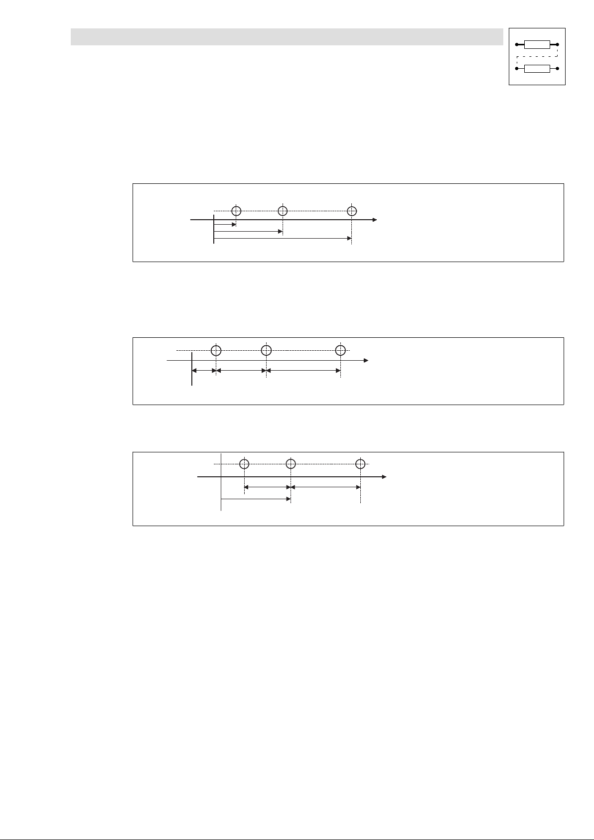
Function library
Positioning control
3.4.1 Dimensions
3.4.1 Dimensions
Absolute dimensions
An absolute target position is a defined position on the traversing path with reference to a zero point.
The target position is approached irrespective of the current position.
Fig. 3−7 Absolute dimensions
Relative dimensions
Relative dimensioning corresponds to incremental dimensioning. Each new target refers to the
preceding target.
0
Fig. 3−8 Relative dimensions
Mixed dimensions
P 1 ( X 1 )
0
X 1 X 2 X 3
X 1 X 2 X 3
P 2 ( X 2 )
P 3 ( X 3 )
x
A b s o l u t e d i m e n s i o n s
R e l a t i v e d i m e n s i o n s
( i n c r e m e n t a l d i m e n s i o n s )
x
M i x e d d i m e n s i o n s
x
9300POS020
9300POS021
Fig. 3−9 Mixed dimensions
0
X 1 X 2 X 3
9300POS022
l
EDSVS9332P−EXT DE 2.0
3−25
Page 54
Function library
Positioning control
3.4.2 Machine parameters
3.4.2 Machine parameters
Example
Purpose
l The physical unit (e.g.: mm, m, degrees) for a unit" is defined via the entry of the machine
parameters.
Function
l Entry of the gearbox ratio under C1202 and C1203, according to the nameplate data of the
gearbox.
C1202
C1203
l Entry of the feed constant under C1204. Enter the number of units (e.g.: mm) to be fed during
5
Motor_speed
Getriebeabtriebsdrehzahl
one revolution at the gearbox output side.
l Entry of the maximum motor speed (n
) under C0011. The limitation mainly applies to the
max
motor.
l Entry of the maximum speed (v
) under C1240. Limitation mainly applies to the entire
max
machine. It should be set lower than the speed that can be attained at maximum motor speed.
The maximum speed v
is considered as the reference for all speed data in the VTVEL
max
variable table.
v
v
max
C1240 v C0011 @
l Entry of the maximum acceleration (a
v n
max
) under C1250.
max
k
@
60 @ i
C1204 @ C1203
60 @ C1202
The maximum acceleration is considered as the reference for all acceleration data given in per
cent in the VTACC variable table.
3−26
EDSVS9332P−EXT DE 2.0
l
Page 55
Function library
Positioning control
3.4.2 Machine parameters
Application example
For positioning a spindle feeding unit is driven via a gearbox. Instead of the standard resolver an
incremental encoder is used as feedback system. The incremental encoder is mounted to the motor
and has a number of increments of 4096 pulses / rev.. The gearbox has a ratio of i = 32 (n
The spindle has a lead of h=10mm. The entries are to be made in mm (1 mm = 1 unit).
motor/nspindle
).
*1
mm
Umdrehung
EXTERTAL/Germany
004 B
CLP460 1196
00500038
(
i +
(
C1202 + z2 @ z4 + 6336
C1203 + z1 @ z3 + 108
z2 @ z4
z1 @ z3
)
+ 58, 667
)
z1 = 12
z2 = 88
z3 = 9
z4 = 72
C0011 + 4000 min
C0025ń113 + EncTTL, 4096inc,5V
C1204 + 5.023
GFL05−2 M HCR 080−32
295 Nm
24 /min (50 Hz)
i=58.667
GT/40000027
Settings:
Code Designation Entry Notes
C0025 Encoder system selection −113− Incremental encoder, IT−4096−5V
C0420 Encoder constant X8 4096 incr (automatically through C0025)
C0490 Position feedback system −1− (TTL encoder) (automatically through C0025)
C0495 Speed feedback system −1− (TTL encoder) (automatically through C0025)
C1202 Gearbox numerator 6336 Numerator corresponds to motor speed
C1203 Gearbox denominator 108 Denominator corresponds to gearbox output speed
C1204 Feed constant 5.023 units/rev mm per rev. at gearbox output
C1207/1 Position encoder gearbox factor, numerator 1 (1/1 = no gearbox between encoder and motor)
C1207/2 Position encoder gearbox factor,
denominator
1 (1/1 = no gearbox between encoder and motor)
Numerator corresponds to motor speed
Denominator corresponds to encoder speed
l
EDSVS9332P−EXT DE 2.0
3−27
Page 56
Function library
Positioning control
3.4.2 Machine parameters
3.4.2.1 Position encoder at material path
Purpose
The gearbox backlash and, if applicable, the slip between the drive, machine, and material path
should be eliminated to increase the accuracy of the calculation of an act. position value.
Function
l The position feedback is ensured by a separate position encoder (C0490) at the material path.
l The speed is fed back through an encoder mounted to the motor shaft (C0495).
Tip!
For defining the dimension of a unit (e.g. mm, cm), machine parameters are entered as if the position
encoder was mounted to the motor shaft.
l There is a ratio between the position encoder and the motor. This ratio is adjusted via the
"encoder/gearbox factor" (C1207/1, C1207/2). Nominator and denominator are entered
according to the speed ratio between the motor and position encoder.
C1207ń1
C1207ń2
l The counting direction of the actual position value (GDC monitor, C1220/3) must increase with
+
n
n
encoder
motor
clockwise rotation of the motor.
Condition: C1206=0 (position setpoint not inverted).
If this is not the case, the counting direction of the position encoder can be inverted as follows:
1. Exchanging the encoder tracks
2. Exchanging the polarity of the actual position (C1208)
Stop!
An opposing setting of the counting directions of the position setpoint and the actual position leads
to a positive feedback in the control loop with the consequence that the drive may overspeed.
l For software version £ V2.1:
– Inverting the counting direction via the actual value polarity (C1208) is not considered while
executing the QSP function.This could lead to a positive feedback in the position control
loop when the QSP or FAIL−QSP function is activated. The drive could accelerate to its
speed limit n
– Therefore the position controller must be switched off during the update of the QSP function
(MCTRL−QSP−OUT=HIGH). In the case of QSP it is not enough to only switch the input
MCTRL−PHI−ON=LOW. The analog input MCTRL−P−ADAPT=0% must be switched e.g. by
means of the function block ASW via MCTRL−QSP−OUT.
in an uncontrolled way (overspeed)!
max
3−28
l For software version > V2.1:
With QSP only the motor encoder is evaluated automatically to stop the motor.
EDSVS9332P−EXT DE 2.0
l
Page 57
Function library
Positioning control
3.4.2 Machine parameters
Stop!
Increasing the ratio between the position encoder and the motor shaft reduces the position
resolution information. This can have a negative effect on the stability of the control loop!
Example (refers to the previous safety information):
In the case of a quadruple evaluation of a position encoder with 1024 increments 4096 increments
are available. Angle of rotation of the motor shaft per encoder increment:
360°
4096incr
+ 0.0879° +0°5.3Ȁ(5.3phaseminutes)
Ratio of the position encoder e.g. i = 128:
0.0879° 128 + 11.25° + 11°15Ȁ(11° and15phaseminutes)
The motor should rotate by 11° to compensate an offset of one increment. A further increase of the
ratio would raise the "compensating path" of the motor.
Permanent slipping of a friction wheel running on the material web (= drive of the position encoder)
results in a faulty actual position value. A web break could accelerate the drive to high speeds due
to the missing actual position value.
Example:
The spindle drive mentioned in the previous example is driven with a separate position encoder
connected to the spindle (gearbox output side).
Settings as described under machine parameters but:
C1206 Polarity of position setpoint −0−: Not inverse
C1207/1 Position encoder gearbox factor, numerator 32 Numerator corresponds to motor speed
C1207/2 Position encoder gearbox factor,
denominator
C1208 Polarity − actual position −0−: Not inverse
−1−: Inverse
1 Denominator corresponds to encoder speed
−1−: Inverse
Reversal of traversing direction
If inverse" is selected, observe the QSP function notes.
l
EDSVS9332P−EXT DE 2.0
3−29
Page 58
Function library
Positioning control
3.4.3 Positioning modes (C1210)
3.4.3 Positioning modes (C1210)
You can select the following positioning modes under C1210:
l Relative positioning ( 3−30)
l Absolute positioning ( 3−32)
l Absolute positioning with saving ( 3−33)
3.4.3.1 Relative positioning
Purpose
l Use with infinite applications, e.g. a cutter.
Function
l Set positioning mode (C1210) = 1.
l Absolute target positions cannot be approached. A fault is indicated (P07).
l The setpoint positions and actual positions are reset prior to a new positioning.
– The current following error is maintained (POS−SETPOS = 0, POS−ACTPOS = current
following error).
l The position limit values (C1223, C1224) determine the maximum feed length in the
corresponding direction.
Tip!
If you do not need the travel range limit switch remove the connection to the digital input terminals
(DIGIN) or switch to +24 V.
l Homing is not necessary, but can be used to set the machine to a defined position.
Rounding error
Without special measures for the mechanical design the path covered of a defined target position
may amount to a fractional number of increments (e. g. 1554.4 inc.). The internal calculation merely
considers the integer part of this value (= 1554 inc.).
For a relative positioning, the momentary target position of which always refers to the previous target
position, rounding errors are propagated with each distance traversed.
This effect can lead to a drifting of the holding position of a conveyor. Therefore it must be observed
that all required target positions can be displayed without decimal position of an increment (see
position resolution).
3−30
EDSVS9332P−EXT DE 2.0
l
Page 59
Function library
Positioning control
3.4.3 Positioning modes (C1210)
Position resolution
l Display via code C1205.
Display of the number of increments with which the units defined by the user are resolved
(incr/unit).
l The position resolution can be used to check for rounding errors.
Calculation example:
C1301/1 = 100.2550 units (position value in VTPOS)
C1205 = 80.0000 inc/unit (position resolution)
Formula:
Feed + C1301[units] @ C1205[incńunit]
8020, 4inc + 100, 2550units * 80, 0000incńunit
A difference of 0.4 inc results from every feed.
Tip!
If it is not possible to have increments without decimal positions, drifting of the holding position can
be avoided by touch−probe positioning.
l
EDSVS9332P−EXT DE 2.0
3−31
Page 60
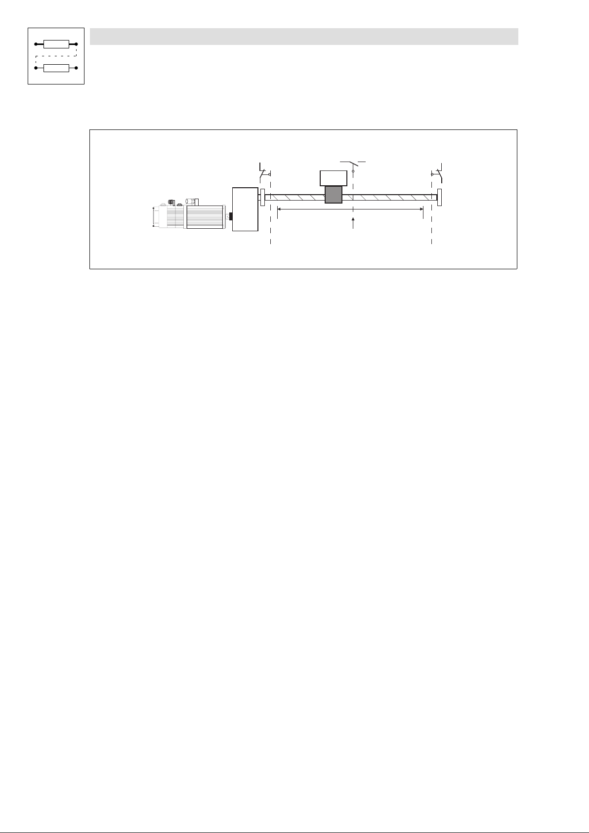
Function library
Positioning control
3.4.3 Positioning modes (C1210)
3.4.3.2 Absolute positioning
POS-LIM-NEG
End of travel switch
negative direction
Fig. 3−10 Example of a machine with finite traversing range
Purpose
l Use in applications with finite traversing range, e. g. in warehousing or handling machines.
Function
l Set positioning mode (C1210) = 0 (default setting)
l Before starting a positioning drive homing must be carried out (output POS−REF−OK=1,
homing status C1284 = REF−OK"). By homing the reference point of the measuring system to
the machine is determined ( 3−46)
l In the absolute positioning mode absolute and relative target positions can be approached.
There are two measuring systems ( 3−34):
– the machine measuring system and
– the real measuring system
POS-REF-MARK
C1224 C1223
Limit position
negative
Home position
Limit position
positive
End of travel switch
positive direction
POS-LIM-POS
S1S2 S3
9300POS025
l The travel range limit switches are located in front of the mechanical stops. They prevent the
drive from touching the stops.
l Adjustable position limiting values (C1223, C1224) prevent the travel range limit switches from
being approached under normal operating conditions. A target position located outside the
position limiting value is not approached. In this case a fault is indicated (P04, P05).
3−32
EDSVS9332P−EXT DE 2.0
l
Page 61

Function library
Positioning control
3.4.3 Positioning modes (C1210)
3.4.3.3 Absolute positioning with saving
Purpose
Homing is not necessary after mains switching.
Function
l Resolver or absolute value encoder (single−turn) to X8 is required as position feedback
system.
l Set positioning mode (C1210) = 2 (absolute positioning with saving).
l The actual position value (POS−ACTPOS) is automatically stored when the mains is switched
off and reinitialised when the mains is switched on. In the OFF state the motor may rotate with
a deviation of max. ±0,5 revolutions so that the actual position value is correctly initialised after
switching on the mains.
All other function are identical with absolute positioning in chapter 3.4.3.2.
Homing status "Homing known"
For absolute positioning the correct machine reference is required ("Homing known")! Output
POS−REF−OK=1 and homing status C1284=REF−OK" .
During commissioning or after homing loss (( 3−46) the drive must be referenced once. According
to the requirements of the application homing can be carried out by homing function", home
setting" or the function POS−ABS−SET".
l With firmware version ³V2.5:
– The current homing status is stored at mains switch−off and is initialised correspondingly
when the mains is switched on again.
At the first commissioning the homing status is not set.
l With firmware version < V2.5:
– Homing status Homing known" is automatically set when the mains is switched on.
Tip!
Although POS−REF−OK = 1 is displayed the drive must be set once during commissioning or after
a homing loss. This serves to re−establish the correct reference to the machine.
l
EDSVS9332P−EXT DE 2.0
3−33
Page 62
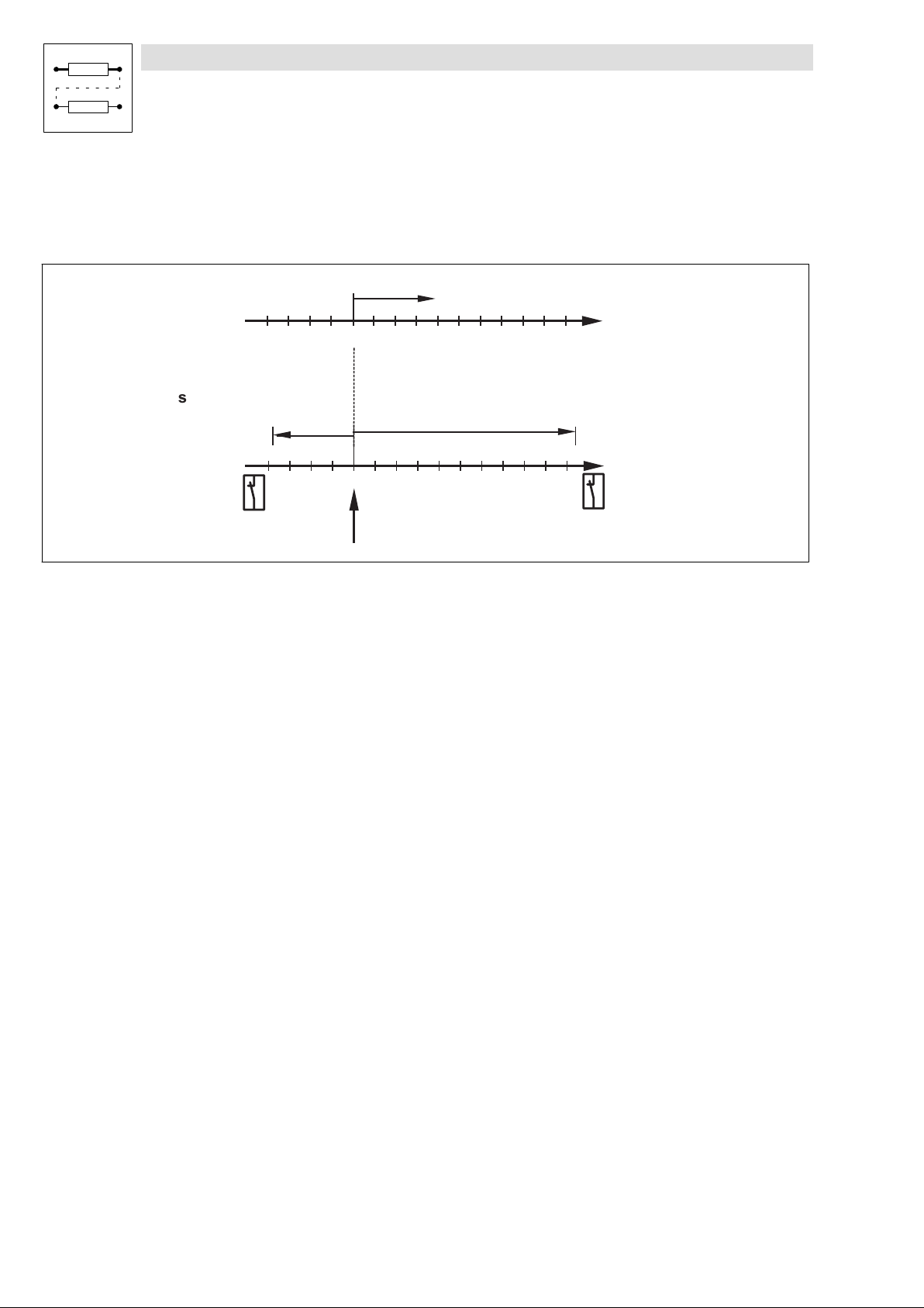
Function library
p
s
Positioning control
3.4.4 Measuring systems
3.4.4 Measuring systems
Purpose
l Limitation of the traversing and determination of reference points for positioning.
R e a l
m e a s u r i n g
C 1 2 2 0 / 1
a c t . t a r g e t p o s i t i o n
s y s t e m
0
M a c h i n e
m e a s u r i n g
y s t e m
L i m i t p o s i t i o n
n e g a t i v e
E n d o f t r a v e l s w i t c h
" P O S - L I M - N E G "
Fig. 3−11 Measuring systems for absolute positioning in default setting (C1225=0, C1227=0)
C 1 2 2 4
H o m e
0
o s i t i o n
C 1 2 2 3
T r a v e r s i n g r a n g e
E n d o f t r a v e l s w i t c h
" P O S - L I M - P O S "
In default setting the reference point = machine zero = real zero ( 3−34).
Reference point
l The reference point is the reference for the connection" of the measuring systems with the
machine.
l Is detected through referencing".
Machine measuring system
L i m i t p o s i t i o n
p o s i t i v e
9300POS006
l The permissible travelling range for the machine measuring system is determined through the
position limit values (C1223 and C1224).
l The machine measuring system has a fixed reference to the machine because of the reference
point.
l The reference point is detected by a reference run" or setting reference" and, usually, not
shifted later. ( 3−46).
Real measuring system
l All indications (e.g.: target positions, position setpoint, and actual position) refer to the real
zero of the real measuring system.
l The real measuring system can be shifted by entering a reference measuring offset.
3−34
EDSVS9332P−EXT DE 2.0
l
Page 63
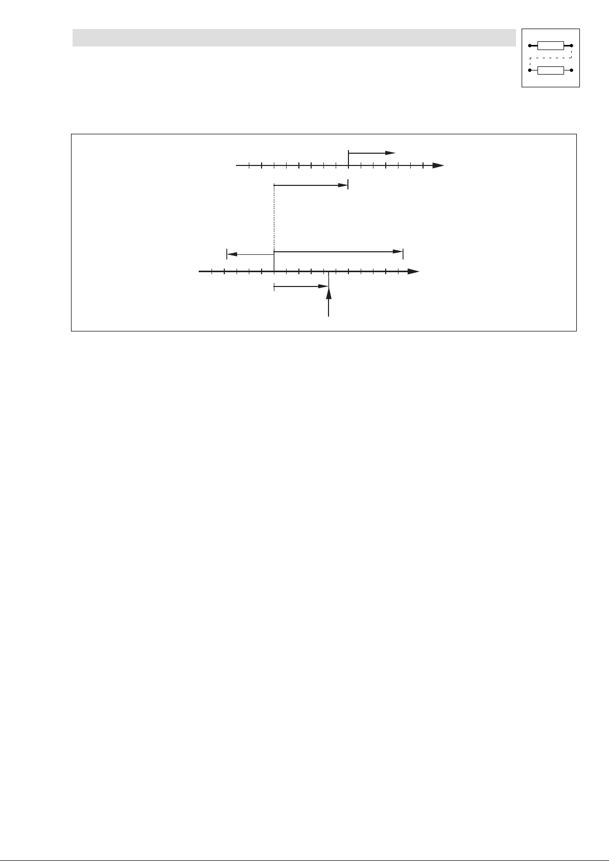
Function library
Positioning control
3.4.4 Measuring systems
3.4.4.1 Measuring systems and zero shifts
R e a l m e a s u r i n g s y s t e m
C 1 2 2 5 ( C 1 2 2 0 / 7 )
C 1 2 2 0 / 1
0
a c t . h o m e o f f s e t
M a c h i n e
m e a s u r i n g
s y s t e m
L i m i t p o s i t i o n
n e g a t i v e
Fig. 3−12 Measuring systems for absolute positioning and zero point shifting
C 1 2 2 4
0
C 1 2 2 7 ( C 1 2 2 0 / 8 )
C 1 2 2 3
a c t . h o m e p o s i t i o n
H o m e po s i t i o n
Shifting of machine zero
Purpose
l The reference run is to be carried out on one side of the traversing range when it is too time
consuming to approach the machine zero.
Function
a c t . t a r g e t p o s i t i o n
L i m i t p o s i t i o n
p o s i t i v e
9300POS007
l Via the home position (C1227) the machine zero point is shifted with regard to the reference
point. The home position is set at the reference point so that with a positive home position the
machine zero point is situated in negative direction.
l The home position (C1227) will only be accepted as actual home position" when being in
reference run" or set reference point" mode.
l The effective actual home position" is indicated under C1220/8 and C1221/8.
l
EDSVS9332P−EXT DE 2.0
3−35
Page 64
Function library
Positioning control
3.4.4 Measuring systems
Shifting of real zero
Purpose
l The target positions must always refer e.g. to the front edge of the workpiece. This means the
real measuring system must be shifted accordingly.
Function
l By means of the reference offset (C1225) the real zero point can be shifted with regard to the
machine zero point. The input of a positive value results in a shift of the real zero point in
positive direction.
l The reference measure offset takes directly effect with the input. The position setpoint
(POS−SETPOS) and the actual position value (POS−ACTPOS) change in accordance with the
change of the reference offset because of the change of its reference point (real zero point).
l The effective actual reference offset" is indicated under C1220/7 and C1221/7.
Tip!
The input value C1225 and the actual reference offset can only be different when using the program
function "set position value".
3−36
EDSVS9332P−EXT DE 2.0
l
Page 65
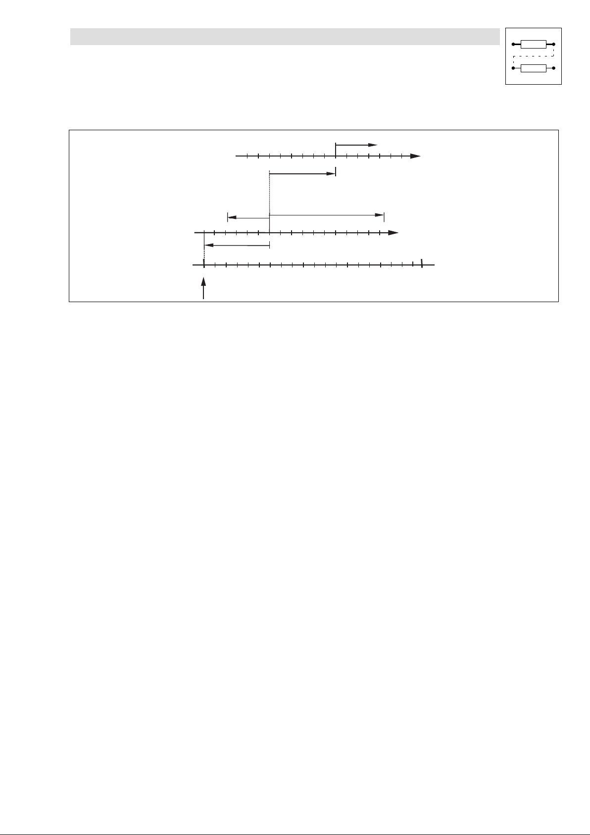
Function library
Positioning control
3.4.4 Measuring systems
3.4.4.2 Measuring systems for absolute value encoders
R e a l m e a s u r i n g s y s t e m
C 1 2 2 5 ( C 1 2 2 0 / 7 )
M a c h i n e
m e a s u r i n g
s y s t e m
L i m i t p o s i t i o n
n e g a t i v e
0
H o m e po s i t i o n
Fig. 3−13 Measuring systems with absolute value encoders
C 1 2 2 4
0
C 1 2 2 7 ( C 1 2 2 0 / 8 )
D i s p l a y r a n g e a b s o l u t e v a l u e e n c o d e r ( C 1 2 2 0 / 5 )
a c t . h o m e p o s i t i o n
For absolute value encoders the same conditions than for positioning apply (see above) concerning
the measuring systems and their references.The only difference is the definition of the reference
point.
Encoder zero is defined as reference point.
l Actual home position
– Use actual home position" to move the machine zero further into the traversing range
(negative value moves the machine zero in positive direction).
– The actual home position" is indicated under C1220/8 in units" and C1221/8 in incr".
C 1 2 2 0 / 1
0
a c t . h o m e o f f s e t
C 1 2 2 3
( I n p u t : n e g . v a l u e )
a c t . t a r g e t p o s i t i o n
L i m i t p o s i t i o n
p o s i t i v e
+ m a x
( O v e r f l o w )
9300POS008
l Initialisation
– After switch−on the "actual home position" is initialised with the "home position".
– Actual home offset" (C1220/7, C1221/7) is set equal to the input value home offset"
(C1225).
l During operation
– After changing, C1227 is not directly transferred to the "actual home position". During
program operation, the transfer can be initialised via the function "Acceptance home
position (C1227)" (setting under PS mode (C1311) = 16).
l Set homing value
– The program function "set reference" enables the machine zero point to be set at the current
position. Therefore the "actual home position" is set to the negative value of the actual
position value (POS−ACTPOS).
– Transfer the value manually under C1220/8 to C1227 and save it under C0003 to ensure that
the setting is available after mains switching.
– The actual reference offset" (C1220/7) is set equal to the input value reference offset"
(C1225) when setting the home position.
l
EDSVS9332P−EXT DE 2.0
3−37
Page 66
Function library
Positioning control
3.4.5 Absolute value encoder
3.4.5 Absolute value encoder
Purpose
The absolute actual position value should be known immediately after mains switching so that
homing is not necessary (for instance if homing is not possible because of machining or processing
circumstances).
l The following functions cannot be executed for positioning with absolute value encoder:
– Homing in program operation,
– manual homing
– Program function set position value" (PS mode C1311 = 5).
Tip!
Homing (to determine the machine zero) can be simulated when using touch probe positioning and
the home position setting function.
3.4.5.1 Absolute value encoder via encoder connection X8
Function
l Connection of sine/cosine absolute value encoders with hyperface communication interfaces
to encoder input X8. Absolute value encoders with a number of increments of 512 periods/rev
and the corresponding data format of the initialisation value of 2
Stegmann SCS70, SCS60).
l The following absolute value encoders can be used as of the device version 33.93xx.EP.2x.62:
Number of
increments
[Periods/rev]
2048 2
1024 2
512 2
256 2
128 2
64 2
Data format
[inc/rev]
16
15
14
13
12
11
Tenderer Type designation
— —
Stegmann SRM50, SRS50
Stegmann SCM70, SCM60
— —
Stegmann SKS36
— —
14
inc/rev can be used (e. g.
3−38
EDSVS9332P−EXT DE 2.0
l
Page 67
Function library
Positioning control
3.4.5 Absolute value encoder
Installation
The absolute value encoder must be mechanically mounted so that the encoder zero point is outside
the travel range. Otherwise a value overflow would occur in the encoder within the travel range. This
would result in a wrong actual position value after mains switching.
Commissioning
Observe the commissioning sequence to avoid a reset of C0420 to default setting.
1. Select the connected absolute value encoder under C0025 or C0495.
– After the selection the fault SD7 is indicated since the encoder has not yet been initialised.
The initialisation only takes place by mains switching. (see step 5.).
2. Enter the number of increments of the absolute value encoder under C0420.
– By entering the number of increments the data format is automatically considered during
initialisation. The data format determines the resolution to be reached of the initialised
absolute value.
3. Carry out a fine adjustment under C1227 (home position).
– By entering a negative value (see Fig. 3−13) the machine zero point is shifted into the
traversing range by means of the home position to enable the input of reasonable position
limit values and monitoring of the traversing range. ( 3−37)
4. Save the settings under C0003.
5. Switch of the mains voltage off and on again.
– The absolute value encoder is initialised. The fault indication SD7 is reset.
Tip!
l Absolute value encoders have a finite area, e. g. 4096 revolutions. Within this area they can
also be moved in a switch−off state; nevertheless they are able to deliver the correct absolute
actual position value after switching on the mains.
l The overflow point of the encoder amounts to 65536 inc/rev × 4096 rev = 268.435.456 inc.
(display: C1221/5)
– When the area to be described is exceeded the fault P12 is indicated.
l
EDSVS9332P−EXT DE 2.0
3−39
Page 68
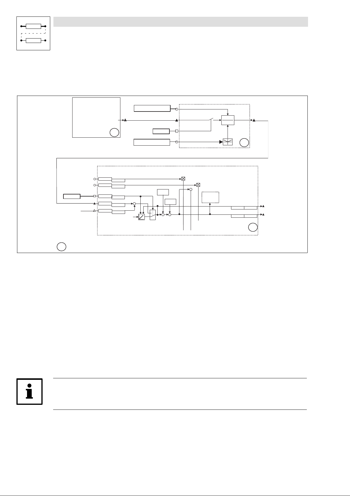
Function library
Positioning control
3.4.5 Absolute value encoder
3.4.5.2 Absolute value encoder via system bus (CAN)
Purpose
l Using absolute value encoders with CAN interface (e. g. laser measuring system).
C A N - I N 3
t r a n s m i t t e d a b s o l u t e
e n c o d e r v a l u e
C A N - I N 3 . D 1
F C O D E - C 4 7 3 / 4
( a d j u s t e d v a l u e )
* *
F C O D E - C 4 7 3 / 5
( a d j u s t e d v a l u e )
C 1 3 6 2 / 7
C 1 3 6 3 / 7
P O S - N O U T - G A I N
C 1 3 6 2 / 5
C 1 3 6 3 / 5
P O S - A B S - S E T
F I X E D - 1
F I X E D 0 %
A b a r b e i t u n g s t a b e l l e
x x
⋅
p r o c e s s i n g l i s t
C 1 3 6 0 / 2 1
C 1 3 6 1 / 2 1
P O S - A B S - I N
C 1 3 6 4 / 2
C 1 3 6 5 / 2
P O S - P H I - A D D
C 1 3 6 6 / 1
C 1 3 6 7 / 1
M C T R L - P H I - A C T
( f e e d b a c k s e l e c t e d u n d e r C 4 9 0 )
( I n f l u e n c e o f f e e d f o r w a r d v a l u e s )
+
+
S e t
( G e n e r a t i o n o f a c t u a l p o s i t i o n )
Fig. 3−14 Absolute value encoder via system bus (CAN)
Function
F I X E D - 1
1
0
h o m e p o s i t i o n
C 1 2 2 7
C 1 2 2 1 / 8
+++
h o m e o f f s e t
C 1 2 2 5
C 1 2 2 1 / 7
-
C O N V P H P H 2 - N U M
C O N V P H P H 2 - I N
C O N V P H P H 2 - A C T
C O N V P H P H 2 - D E N
+
-
P O S - T P
( T o u c h P r o b e )
C O N V P H P H 2
C O N V P H P H 2
x
y
1
1 8
P O S - A B S - V A L
P O S - A C T P O S
- O U T
P O S
C 1 2 2 1 / 1 6C 1 2 2 0 / 1 6
C 1 2 2 1 / 3C 1 2 2 0 / 3
2 0
9300POS009
l All absolute value encoders with a CAN interface to specification CAL DS−301" (CAN open)
can be used.
l The CAN parameters, especially CAN baud rate, CAN identifier, and cycle time are to be set
accordingly. The set CAN parameters must be storable in the encoder!
l The absolute value read via, for instance, CAN−IN3.D1 is sent to the input POS−ABS−IN".
l Input POS−ABS−SET" is assigned to 1 signal (e.g.: FIXED1) and thus the acceptance of the
absolute value at input POS−ABS−IN is activated.
l POS−ABS−SET = HIGH sets the homing status REF−OK" automatically, homing is therefore
not necessary.
l The encoder resolution is adapted to the internal position resolution of 65536 inc/rev via the
function block CONVPHPH2. The adaptation factor is entered via the free codes C473/4 and
C473/5.
Tip!
The input POS−PHI−ADD and the output POS−ABS−VAL are available as of firmware version ³ 2.5
3−40
EDSVS9332P−EXT DE 2.0
l
Page 69
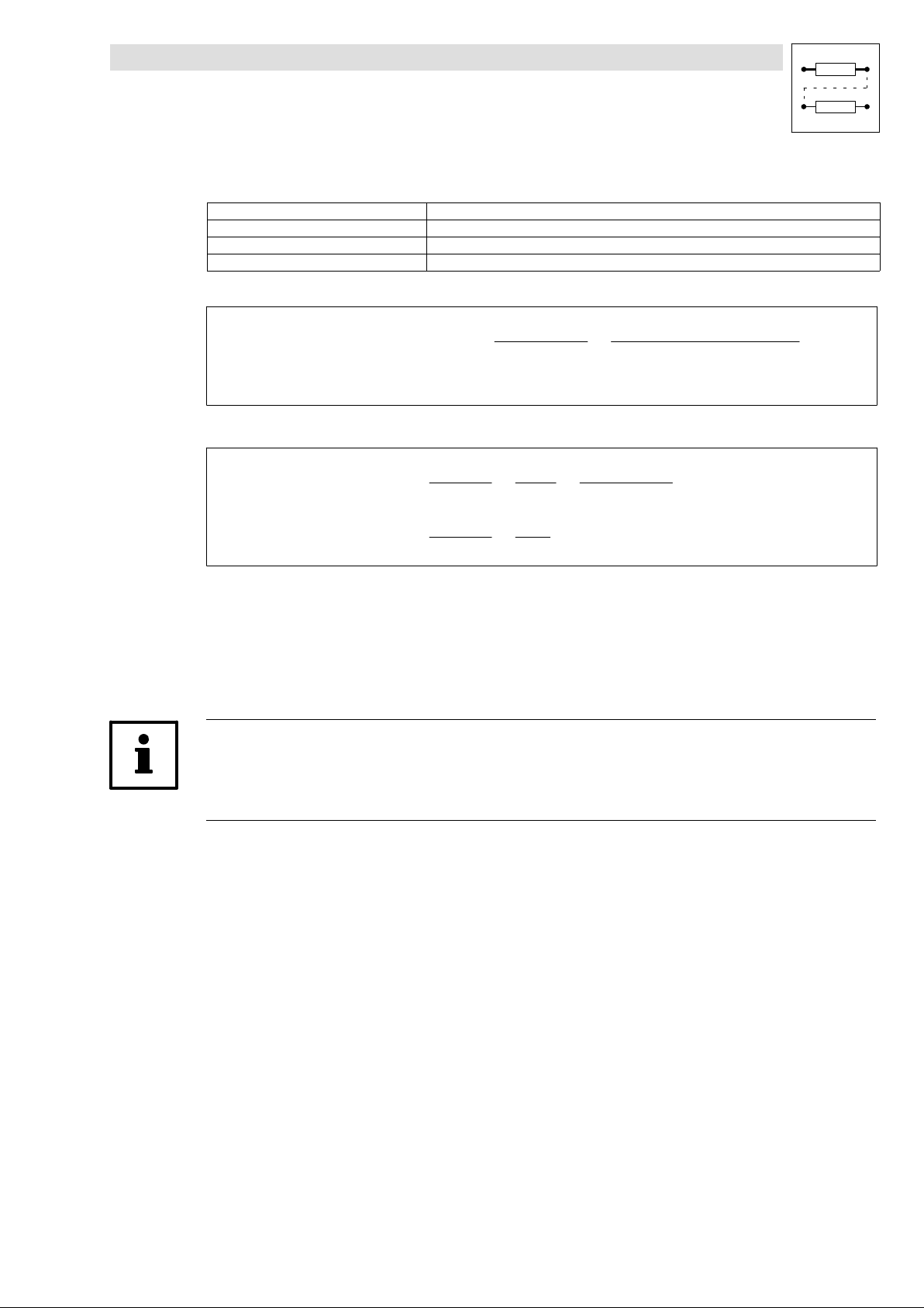
Function library
Positioning control
3.4.5 Absolute value encoder
Example for the adaptation of the encoder resolution:
Gearbox between encoder and drive i = 30
Effective wheel diameter d = 50 mm
Position resolution of the measuring system A
Internal position resolution (fix) A
Position resolution of the measuring system (with regard to motor side):
= 8 inc/mm
meas
= 65536 inc/rev
internal
+
Ax
mess
Ax
+ 41, 87incńrev
mess
ǒ
p
8incńmm @ 50mm @ 3, 14
(
@ d @
A
mess
)
i
+
30
Ǔ
Adaptation factor for CONVPHPH2:
C0473ń4
C0473ń5
C0473ń4
C0473ń5
l Read the absolute value at POS−ABS−IN under consideration of the setpoint polarity (C1206)
+
+
A
intern
Ax
mess
1565
1
65536incńrev
+
41, 87incńrev
and the actual value polarity (C1208).
l The actual home position" (C1220/8) is then added and the actual home offset" (C1220/7) is
subtracted.
l The actual home position" is set equal to C1227 if POS−ABS−SET = HIGH during initialisation
(switch on).
Tip!
The display values under C1220/5 and C1221/5 only correspond to the absolute value of the encoder
read when using the absolute value encoder through X8!
l
EDSVS9332P−EXT DE 2.0
3−41
Page 70
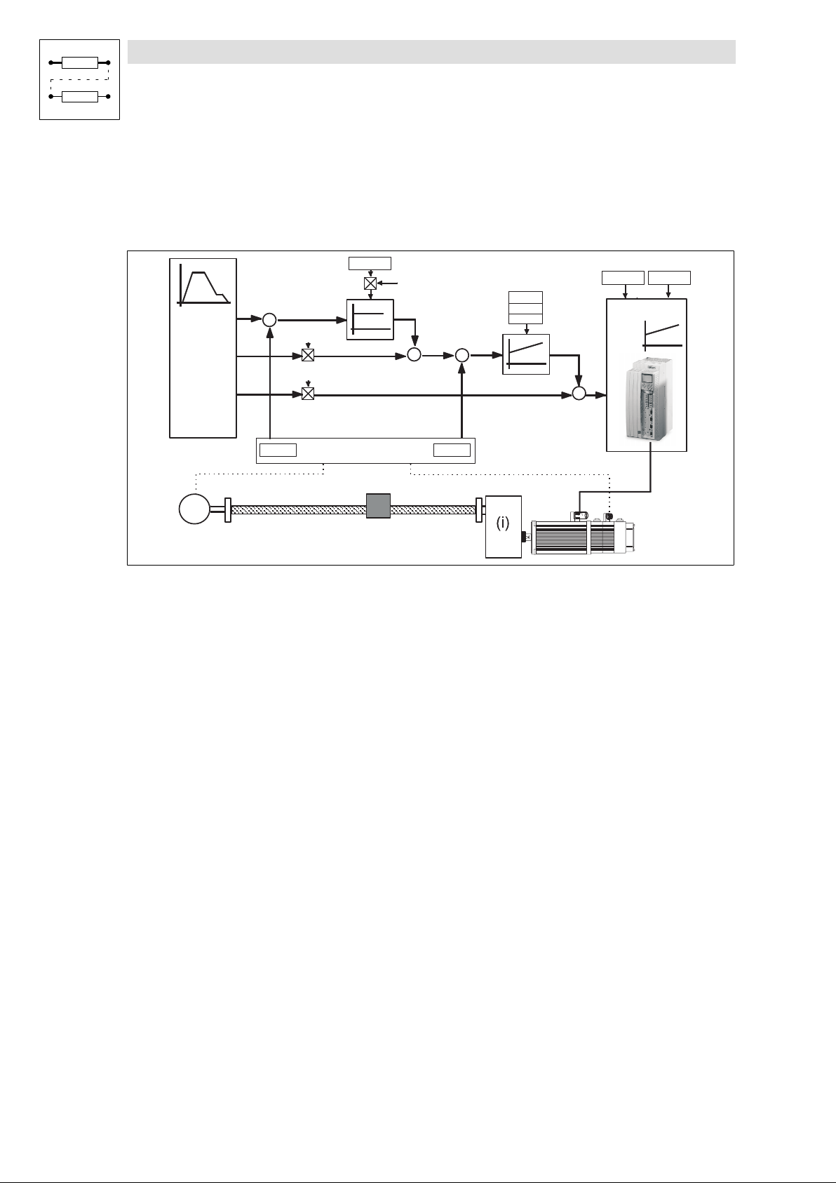
Function library
Positioning control
3.4.6 Control structure
3.4.6 Control structure
The following graphic representation provides an overview of the control structure realised in the
9300 servo position controller. It shows the parameters and codes that are decisive for the
adjustment of the control loops.
Vp
POS
SETPOS
NOUT
(MOUT)
+
(-)
actual
position
C0490
NOUT-GAIN
MOUT-GAIN
Feedback systems
C0254
MCTRL-P-ADAPT
+
+
+
actual
speed
C0495
C0070
C0071
C0072
(-)
Enc
optional
Adjustment points of the control loops
l Speed controller (PID controller)
– C0070: Gain Vp
– C0071: Integral−action time Tn
n
n
– C0072: Rate time Tdn (default setting Tdn = 0 is usually not changed)
– POS−NOUT−GAIN: Speed feedforward control (default setting: 100%)
Vp
Tn
Td
Vp
C0075 C0076
Curent control
PWM
+
+
Tn
9300POS039
l Position controller (P controller)
– C0254: Gain Vp position controller
– MCTRL−P−ADAPT for adapting the gain depending on e.g. the speed
l Current controller (PI controller)
– C0075: Vp (default setting is usually not changed)
– C0076: Tn (default setting is usually not changed)
3−42
EDSVS9332P−EXT DE 2.0
l
Page 71

Function library
Positioning control
3.4.6 Control structure
Important signals for adjusting the control loops
The following signals are especially suitable for evaluating the positioning behaviour and control
features:
l POS−NOUT: Speed setpoint, 100 % º n
l MCTRL−NACT: Actual speed value, 100 % º n
l MCTRL−MSET2: Actual torque, 100 % º M
l POS−POUT−NORM: Actual following error, 100 % º Following error tolerance (C1218/1)
max
(C0011)
max
(C0057)
max
(C0011)
Tip!
The code table can be found in the system manual, document number EDSVS9332P.
l
EDSVS9332P−EXT DE 2.0
3−43
Page 72
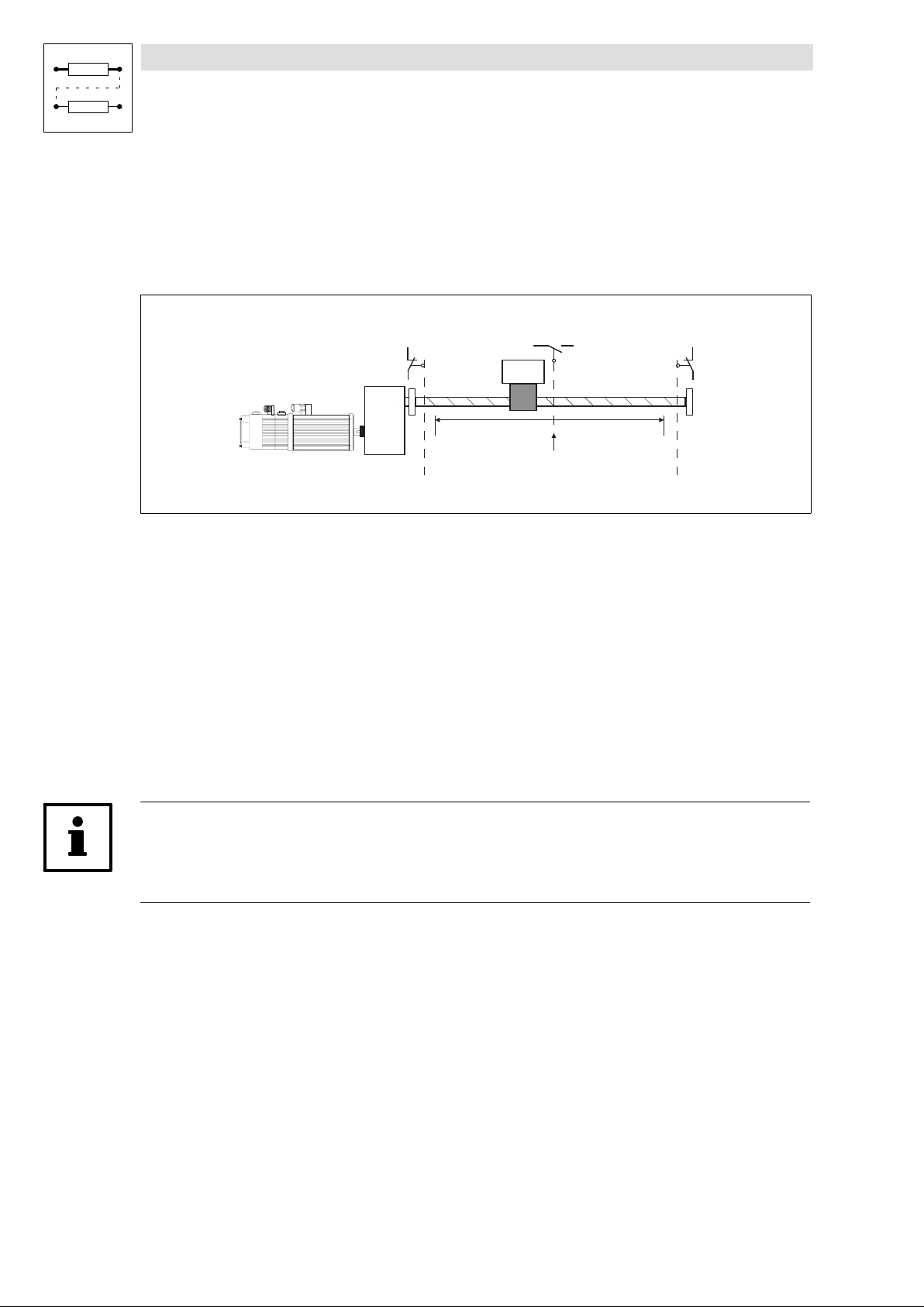
Function library
Positioning control
3.4.7 Travel range limits
3.4.7 Travel range limits
You can prevent the mechanical stops of the limited travel range from being touched by
l the travel range limit switches (hardware),
l the position limiting values (software).
Fig. 3−15 Example of travel range limits
3.4.7.1 End of travel range limit switch
l The travel range limit switches are connected via the digital input terminals X5/E1 and X5/E2.
l In the default setting, X5/E1 and X5/E2 are configured for the function block inputs
POS−LIM−POS and POS−LIM−NEG and are LOW active (protected against open circuit).
l A travel range limit switch indicates the fault P01 or P02 under the following circumstances:
– In program operation if the speed setpoint (POS−NOUT) is unequal 0.
– In manual operation if the drive moves outside the traversing range.
– During homing, if the drive does not reverse when reaching the limit switch.
POS-LIM-NEG
Limit position
negative
End of travel switch
negative direction
POS-REF-MARK
C1224 C1223
Limit position
Home position
positive
POS-LIM-POS
S1S2 S3
End of travel switch
positive direction
9300POS025
l In the event of a failure the drive brakes to standstill using the function FAIL−QSP" (default
setting); the ramp time QSP−Tif" can be adjusted under C0105.
Tip!
The travel range limit switches should be mounted in positions that provide enough braking distance
for the drive in the event of a failure.
3−44
EDSVS9332P−EXT DE 2.0
l
Page 73
Function library
Positioning control
3.4.7 Travel range limits
3.4.7.2 Position limit values (C1223, C1224)
l Position limit values (C1223, C1224) define the permissible traversing range of the drive.
l The reference point for the position limiting values always is the machine zero point. Shifting
the real zero point does not result in a shift of the position limiting value with the regard to the
mechanical travel range limits. ( 3−34).
l Exceeding the limit positions causes a fault (P04, P05).
l In the event of a failure the drive brakes to standstill using the function FAIL−QSP" (default
setting); the ramp time QSP−Tif" can be adjusted under C0105.
Code Name Limits Note
C1223 Pos.limit+ 0.0000 ... 214000.0000 [units] Positive position limiting value
C1224 Pos.limit− −214000.0000 ... 0.0000 [units] Negative positive limiting value
Tip!
l The settings should not allow that the end of travel limit switches are reached during
operation.
l The max. traversing range amounts to ±16000 revolutions of position encoder.
l If the position limiting values exceed the internal area, the warning P18 (internal limitation) is
triggered. The limiting values are internally automatically limited to the possible area.
Positioning can only take place within these limits.
l The input values under C1223 and C1224 remain the same and need to be modified by the
user (if necessary).
l Display of internally limited position limiting values under C1220/10 and C1220/11 [units] and
under C1221/10 and C1221/11 [incr.].
l
EDSVS9332P−EXT DE 2.0
3−45
Page 74

Function library
Positioning control
3.4.8 Homing
3.4.8 Homing
Determination of the mechanical reference point for measuring systems.
After homing, the drive is in a defined position.
Functions
l Homing ( 3−46)
l Homing end ( 3−47)
l Homing status ( 3−48)
l Homing modes ( 3−49)ff.
l Second homing speed ( 3−56)
l Set homing value( 3−57)
3.4.8.1 Homing
Purpose
Definition of the reference point in the absolute or relative positioning mode.
Function
l Selection of a sequence suitable for homing ( 3−49).
l Setting of the homing speed under C1242
– Setting of a second homing speed under C1241 (if necessary) ( 3−56)
l Setting of the homing acceleration under C1251
l Definition of the final homing point under C1209.
l Execution of homing in
– Manual operation via "manual referencing" ( 3−67).
– Program operation (GDC dialog "Programming" under PS mode" or selection under
C1311/x=3, program set mode)
Homing procedure
l The homing status POS−REF−OK is reset (see ( 3−48)) and the current reference offset
initialised using the value entered under C1225.
l Homing is started and carried out according to the mode selected under C1213.
l If the reference point is found, the home position (C1227) is set and the reference offset
(C1225) is added. The position data now refer to the real zero point (see Fig. 3−12).
l The homing status POS−REF−OK is set.
3−46
EDSVS9332P−EXT DE 2.0
l
Page 75

Function library
Positioning control
3.4.8 Homing
3.4.8.2 Final homing point
Purpose
l Determination of the final point where the drive stops after homing.
l Avoid reversing while homing
Selection of the final homing point (C1209)
l C1209 = 0 (default setting):
Drive stops at reference point (index pulse / zero position / touch probe) or returns to that
point.
l C1209 = 1:
Drive does not stop until it has reached the real zero point. The distance covered additionally
is determined by the reference offset and the home position.
l C1209 = 61:
Drive does not stop until it has reached the target position VTPOS−NO−60 (parameter
C1301/60). The distance covered additionally is determined by the reference offset, the home
position, and the target position.
l C1209 = 71:
Drive stops at target position VTPOS−NO−70 (function block input). The distance covered
additionally is determined by the reference offset, the home position and the target position.
l C1209 = 101:
Drive stops at target position VTPOS−NO−100 (teach−in value). The distance covered
additionally is determined by the reference offset, the home position, and the target position.
Tip!
When the drive must not reverse during homing:
l Select real zero as final homing point (C1209) and
l Enter reference offset.
Like this, the braking distance after homing is always long enough.
l
EDSVS9332P−EXT DE 2.0
3−47
Page 76

Function library
Positioning control
3.4.8 Homing
3.4.8.3 Homing status (POS−REF−OK)
The homing status is indicated via the function block output POS−REF−OK" and displayed under
C1284.
The homing status is displayed as "Reference known" when the measuring systems have a defined
reference to the machine. Absolute positioning ( 3−32) or ( 3−33) is only possible after a defined
reference has been created.
The output POS−REF−OK is set if
l homing is completed,
l the program function Set reference" is set,
l the absolute value encoder is selected as position feedback (C0490 = 4).
l Set Fb input POS−ABS−SET = 1.
l C1210 = 2 (absolute positioning with saving)
The output POS−REF−OK is reset by
l Start of homing
l Writing to the following codes:
– C0011 (Nmax)
– C0490 (feedback system for the position controller)
Note:
Please take into consideration that codes C0490 and C0025 have an impact on each other.
A subsequent change of one of the codes overwrites the other.
– C1202 (Gearbox factor, numerator)
– C1203 (Gearbox factor, denominator)
– C1204 (Feed constant)
– C1207/1(Position encoder gearbox factor, numerator)
– C1207/2 (Position encoder gearbox factor, denominator)
– C1210 (Positioning mode)
l The following errors occur:
– NMAX (limit speed from C0596)
– P12 (encoder limit exceeded)
– SD2 (resolver error) if resolver has been selected as position feedback system (C0490=0),
SD7 (absolute value encoder).
l In relative positioning mode (C1210=1) if Prg−reset is carried out during a running positioning
process.
3−48
EDSVS9332P−EXT DE 2.0
l
Page 77
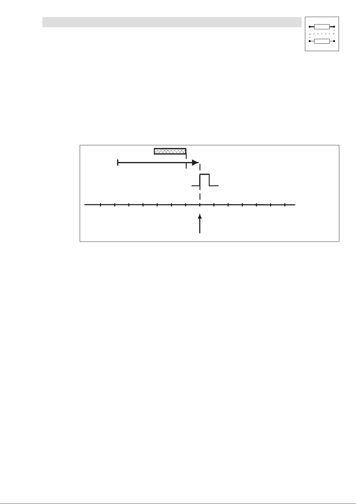
Function library
Positioning control
3.4.8 Homing
3.4.8.4 Homing modes 0 and 1
Purpose
l Simple homing in all positioning modes (C1210 = 0, 1, 2).
l The homing switch (POS−REF−MARK) must be in direction of the movement.
Move to reference point via homing switch
Mode 0: Traversing direction to positive end of travel range limit switch
Set C1213 = 0.
Homing switch (POS-REF-MARK)
Direction
Zero pulse/zero position
Fig. 3−16 Move to reference point via homing switch
Function sequence
l Move to the reference point with homing speed (C1242) towards positive end of travel range
limit switch overtravelling the homing switch.
l The reference point is at the first zero pulse / zero position of the position encoder after leaving
the homing switch.
The drive can be on the homing switch before homing.
Mode 1: Traversing direction to negative end of travel range limit switch
Set C1213 = 1.
Function sequence
l Like mode 0, but the drive traverses in negative direction to travel range limit switch.
Home position
9300pos052
l
EDSVS9332P−EXT DE 2.0
3−49
Page 78
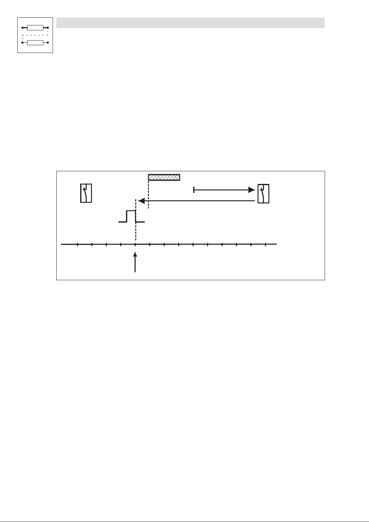
Function library
Positioning control
3.4.8 Homing
3.4.8.5 Homing modes 2 and 3
Purpose
l Homing in absolute positioning mode (C1210 = 0, 2), with finite traversing range and existing
travel range limit switches (POS−LIM−xxx).
l The homing switch (POS−REF−MARK) is always found. In the worst case the entire traversing
range will be searched.
Approach end of travel range limit switch, reverse and move to reference point via homing
switch
Mode 2: Traversing direction to positive end of travel range limit switch
Set C1213 = 2.
Homing switch (POS-REF-MARK)
End of
travel switch
(POS-LIM-NEG)
Fig. 3−17 Move to POS−LIM−POS, reverse, move to reference point via POS−REF−MARK
Zero pulse / Zero position
Home position
Function sequence
l Move to positive travel range limit switch with homing speed C1242.
l Reverse there and move beyond the reference switch to the reference point with homing
speed C1242. In this case no fault (PO2) is indicated!
l The reference point is at the first zero pulse / zero position of the position encoder after leaving
the homing switch.
l If the drive is already on the positive end of travel range limit switch before homing, it is
reversed immediately.
l If the drive is positioned at the reference switch when homing is started, the switch will be
overtravelled. The drive then goes on to the limit switch and reverses there.
End of
travel switch
(POS-LIM-POS)
9300pos053
3−50
EDSVS9332P−EXT DE 2.0
l
Page 79
Function library
Positioning control
3.4.8 Homing
Mode 3: Traversing direction to negative end of travel range limit switch
Set C1213 = 3.
Function sequence
l As "Traversing direction to positive end of travel range limit switch", but the drive moves
towards the negative end of travel range limit switch.
l No fault indication (PO2)
Tip!
The limit switch (POS−LIM−xxx) can be used as homing switch (POS−REF−MARK) at the same time
to save initiators.
3.4.8.6 Homing modes 4 and 5
Purpose
l Simple homing in all positioning modes (C1210 = 0, 1, 2).
l The homing switch (POS−REF−MARK) will not be overtravelled. Positions to the right of the
homing switch cannot occur due to the mechanical design.
l The homing switch must be in direction of the movement.
l
EDSVS9332P−EXT DE 2.0
3−51
Page 80
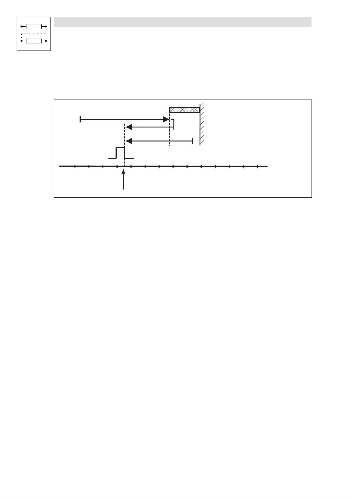
Function library
Positioning control
3.4.8 Homing
Move to homing switch, reverse and move to reference point
Mode 4: Traversing direction to the positive end of the travel range limit switch
Set C1213 = 4.
?
Zero pulse / Zero position
Home position
Fig. 3−18 Move to POS−REF−MARK, reverse and move to reference point
Function sequence
Reference switch
(POS-REF-MARK)
1
9300pos034
l Move towards travel range limit switch with homing speed C1242 up to homing switch
(case ).
l Reverse there and move to the reference point. The homing switch must be assigned during
the entire homing process!
l The reference point is at the first zero pulse / zero position of the position encoder after leaving
the homing switch.
l If the drive is already positioned on the homing switch before homing it is reversed
immediately (case ).
Mode 5: Traversing direction to negative end of travel range limit switch
Set C1213 = 5.
Function sequence
l Like mode 4, but the drive traverses in negative direction of travel range limit switch.
3−52
EDSVS9332P−EXT DE 2.0
l
Page 81
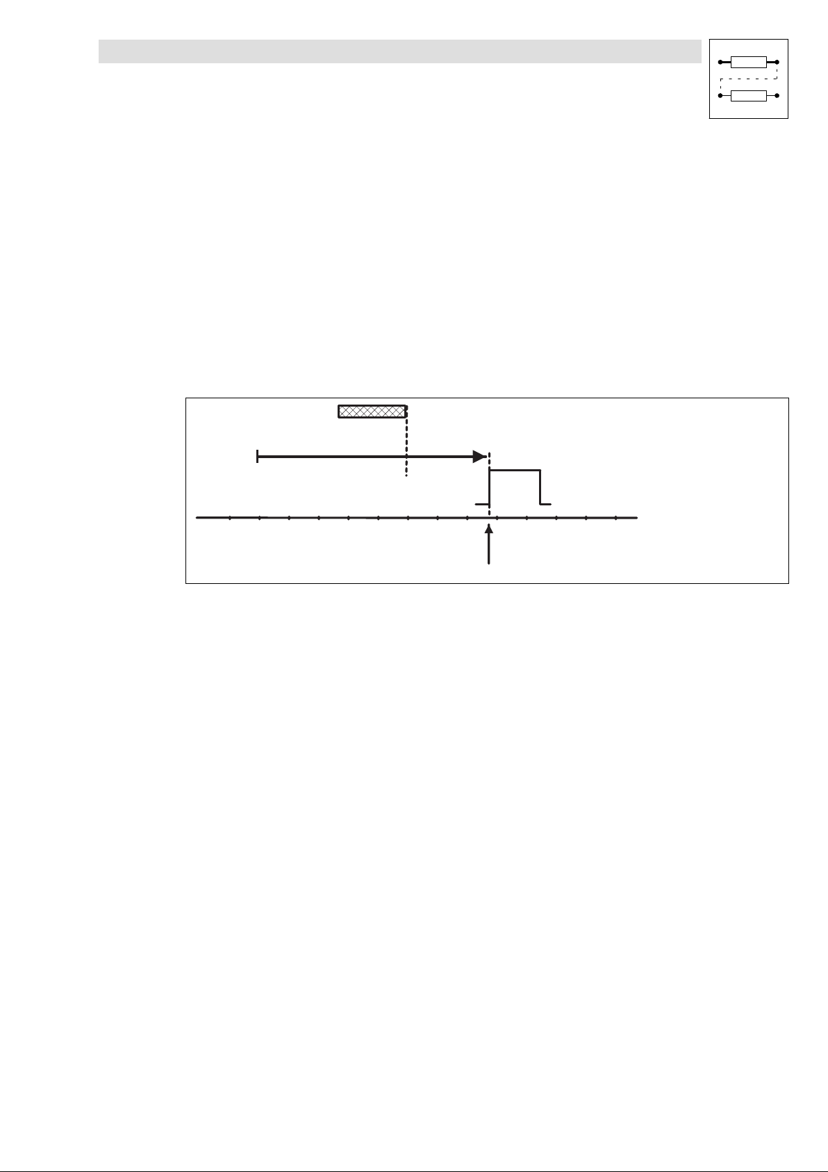
Function library
Positioning control
3.4.8 Homing
3.4.8.7 Homing modes 6 and 7
Purpose
l Homing in all positioning modes (C1210 = 0, 1, 2).
l Use of touch probe if the index pulse does not appear at the same place in a reproducible
form due to the mechanical constellation. The index signal can also be mechanically shifted
after a motor exchange.
l The homing switch (POS−REF−MARK) must be in direction of the movement.
Travelling to TP signal via homing switch
Mode 6: Traversing direction to the positive end of the travel range limit switch
Set C1213 = 6.
Homing switch (POS-REF-MARK)
Fig. 3−19 Move to TP signal via POS−REF−MARK
The following settings are necessary:
l Select terminal for TP initiator via C1214.
– C1214 = 1 ¢ terminal X5/E1.
– C1214 = 2 ¢ terminal X5/E2.
– C1214 = 3 ¢ terminal X5/E3.
– C1214 = 4 ¢ terminal X5/E4 (This setting is recommended by LENZE).
l Select edge of the TP input via C1215.
– C1215 = 0 ¢ LOW−HIGH edge.
– C1215 = 1 ¢ HIGH−LOW edge.
Function sequence
l Move to the home position with homing speed (C1242) towards positive end of travel range
limit switch overtravelling the homing switch.
l After leaving the homing switch the reference point is determined by the TP signal. TP signals
that occurred before are ignored.
TP signal
Home position
9300pos054
l
l The drive can be on the homing switch before homing.
Mode 7: Traversing direction to negative end of travel range limit switch
Set C1213 = 7.
Function sequence
l As "Traversing direction to positive end of travel range limit switch", but the drive moves
towards the negative end of travel range limit switch.
EDSVS9332P−EXT DE 2.0
3−53
Page 82
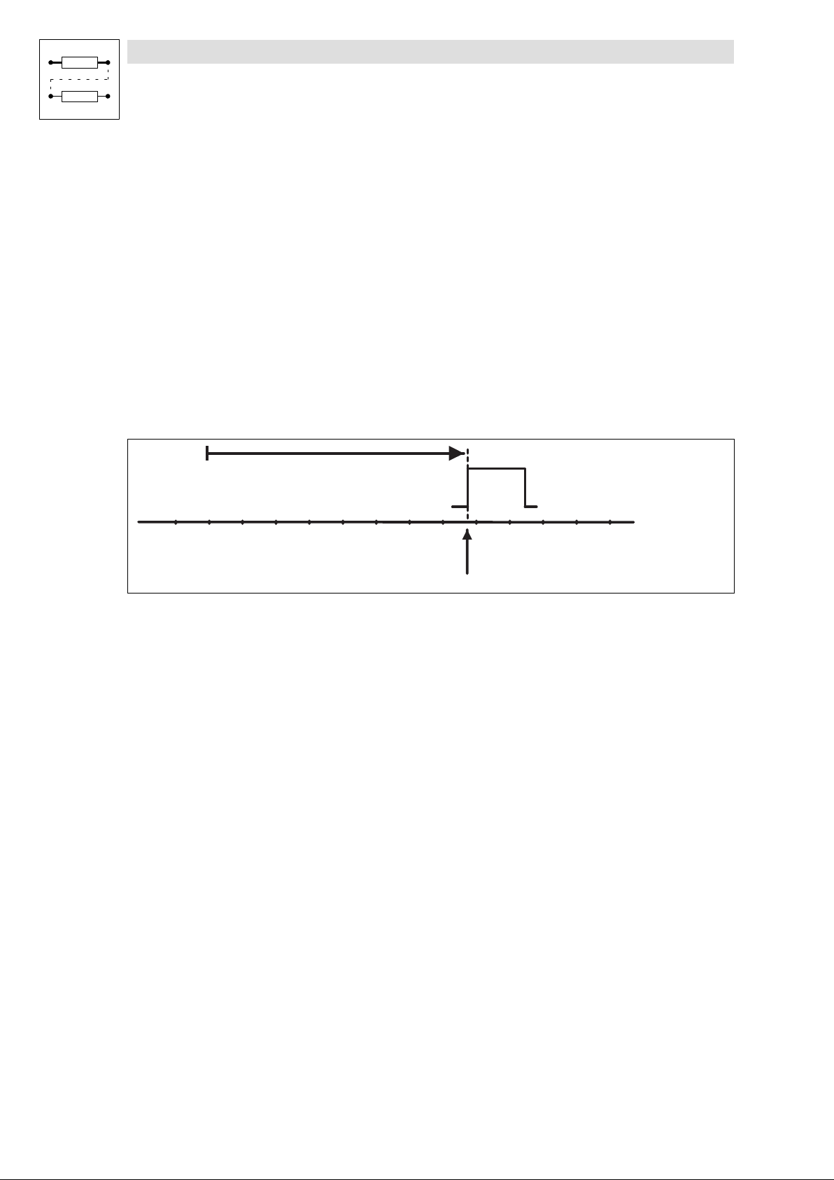
Function library
Positioning control
3.4.8 Homing
3.4.8.8 Homing modes 8 and 9
Purpose
l Homing in all positioning modes (C1210 = 0, 1, 2).
l Use of touch probe if the index pulse does not appear at the same place in a reproducible
form due to the mechanical constellation. The index signal can also be mechanically shifted
after a motor replacement.
l The touch probe must be situated in direction of movement. The TP must not be assigned
before starting homing.
Directly travel to TP signal
Mode 8: Traversing direction to the positive end of the travel range limit switch
Set C1213 = 8.
Fig. 3−20 Move to TP signal
The following settings are necessary:
l Select terminal for TP initiator via C1214.
– C1214 = 1 ¢ terminal X5/E1.
– C1214 = 2 ¢ terminal X5/E2.
– C1214 = 3 ¢ terminal X5/E3.
– C1214 = 4 ¢ terminal X5/E4 (This setting is recommended by LENZE).
l Select signal of the TP input via C1215/x.
– C1215/x = 0 ¢ LOW−HIGH edge.
– C1215/x = 1 ¢ HIGH−LOW edge.
Function sequence
l Move to the TP signal with homing speed (C1242) towards positive end of travel range limit
switch.
TP signal
Home position
9300pos055
3−54
l The first TP signal determines the reference point.
Mode 9: Traversing direction to negative end of travel range limit switch
Set C1213 = 9.
Function sequence
l As "Traversing direction to positive end of travel range limit switch", but the drive moves
towards the negative end of travel range limit switch.
EDSVS9332P−EXT DE 2.0
l
Page 83
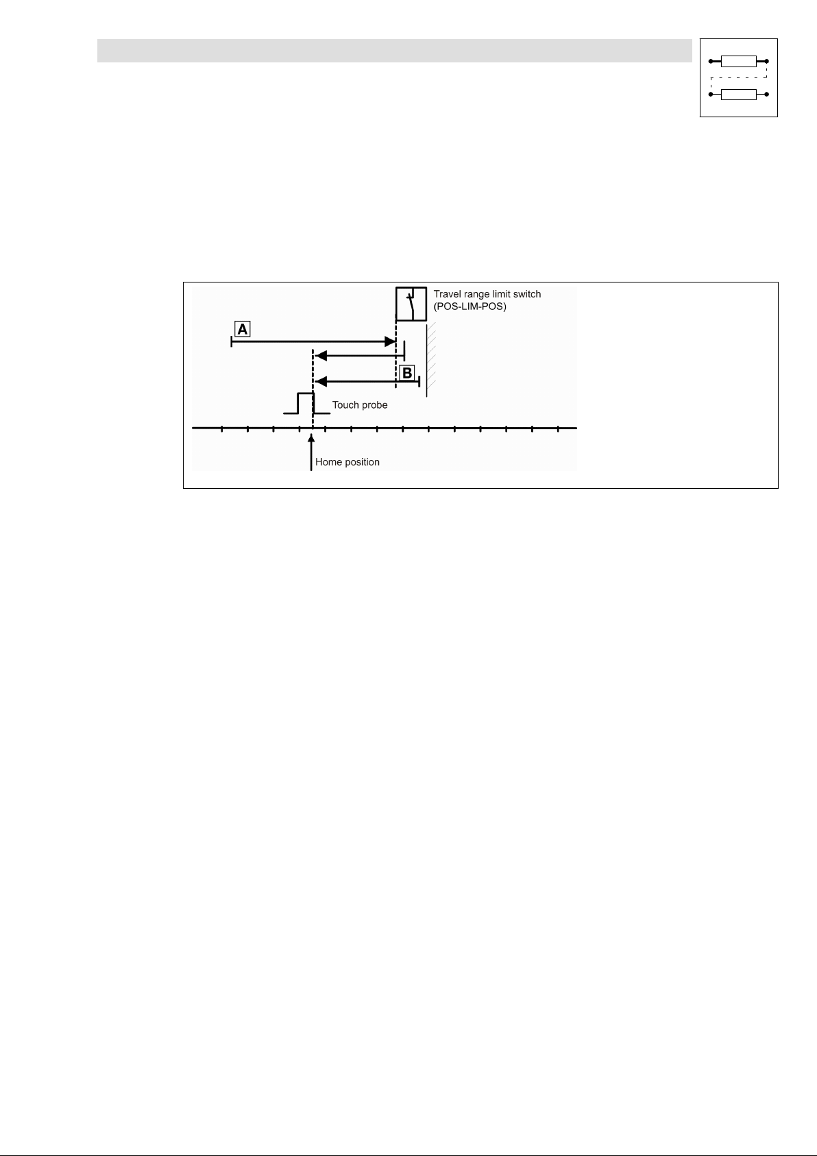
Function library
Positioning control
3.4.8 Homing
3.4.8.9 Homing modes 10 and 11
Purpose
l Homing in absolute positioning mode (C1210 = 0, 2).
l Use of touch probe if the index pulse does not appear at the same place in a reproducible
form due to the mechanical constellation. The index signal can also be mechanically shifted
after a motor replacement.
9300pos030
Mode 10: Traversing direction to positive POS−LIM−POS
Traverse in positive direction up to POS−LIM−POS, reverse there and reference to TP (case). During
reversing the limit switch must always be assigned!
l Move to positive end of travel range limit switch in positive direction with homing speed
C1242.
l Reverse and move in negative direction to the reference point via touch probe with homing
speed C1242 or C1241 (depending on the setting in C1216, see second homing speed).
l If the drive is positioned on the positive end of the travel range limit switch before homing, it
directly travels in negative direction (case).
l The reference point is at touch probe + home position C1227.
Monitoring P02 does not respond!
l
EDSVS9332P−EXT DE 2.0
3−55
Page 84

Function library
Positioning control
3.4.8 Homing
Mode 11: Traversing direction to negative POS−LIM−NEG
Travel in negative direction up to POS−LIM−NEG, reverse there and reference to TP. TP can also be
the negative edge of POS−LIM−NEG.
Otherwise identical with mode 10
Tip!
In order to save initiators the limit switch (POS−LIM−xxx) can be simultaneously used as touch probe.
The TP input is selected under C1214.
Since the limit switches are factory−set to LOW active, select the rising edge for TP (C1215/x = 0).
After homing, the drive must not directly stop on the reference point, since this may result in a
response of the travel range limit switches. The reference limit point must be set accordingly.
3.4.8.10 Second homing speed
Second homing speed
A second homing speed (C1241) can be activated by C1216.
Homing procedure with activated second homing speed:
Modes 0, 1:
To POS−REF−MARK at first speed, then at second speed.
Modes 2, 3:
At first speed to limit switch POS−LIM−POS (mode 2) or POS−LIM−NEG (mode 3), second speed after
reversing.
Modes 4, 5:
To limit switch POS−REF−MARK at first speed, second speed after reversing.
Modes 6, 7:
To POS−REF−MARK at first speed, then at second speed.
Modes 8, 9:
Only at first speed to reference point via TP.
Modes 10, 11:
To limit switch POS−LIM−POS or POS−LIM−NEG at first speed, second speed after reversing.
3−56
EDSVS9332P−EXT DE 2.0
l
Page 85
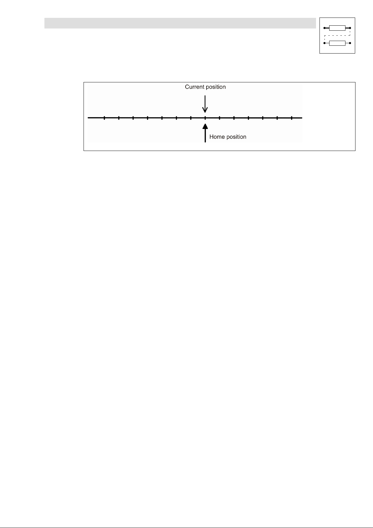
Function library
Positioning control
3.4.8 Homing
3.4.8.11 Set homing value
Purpose
If the home position is known (e.g. by a higher−level master system), homing is not necessary.
Function
l Select "Set homing value" under "PS mode" in the PS (C1311 = 4).
l In this case, the current position is the reference point.
l The zero points of the measuring systems are set accordingly ( 3−34).
9300pos042
l
EDSVS9332P−EXT DE 2.0
3−57
Page 86
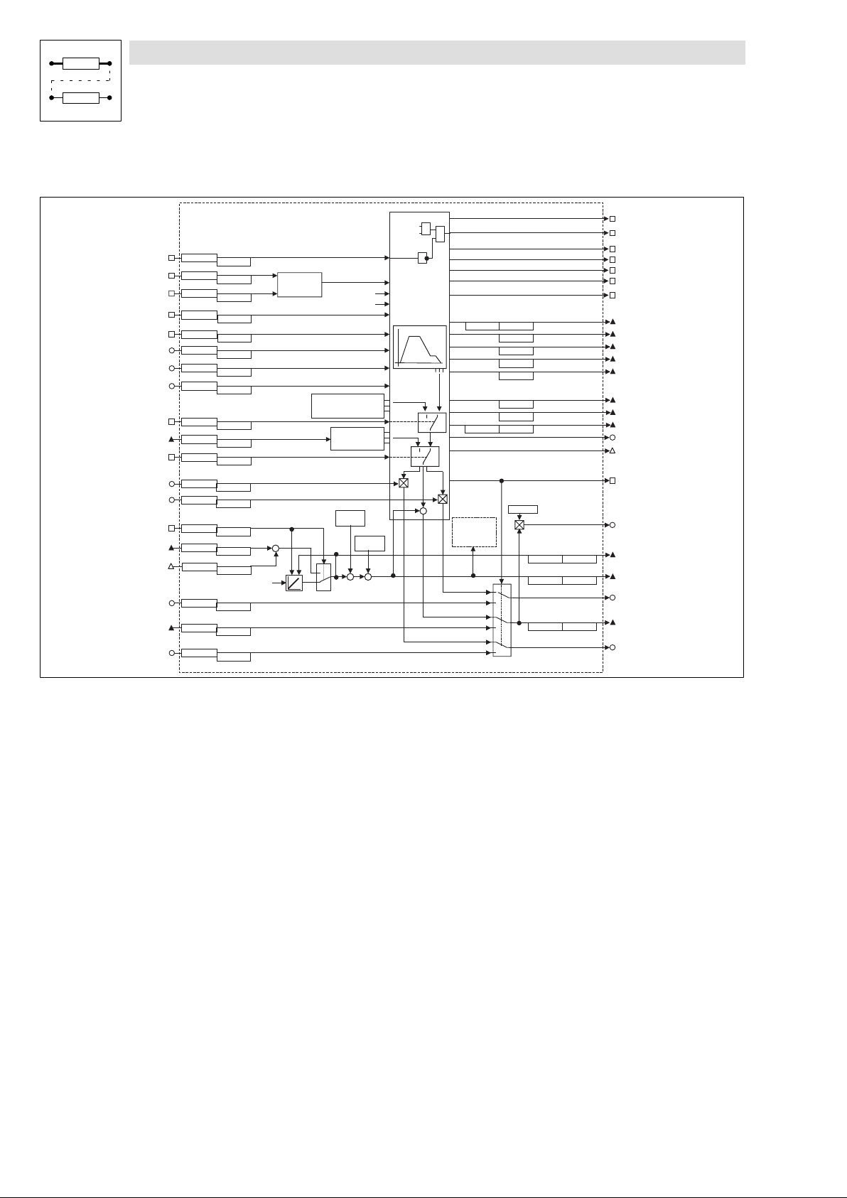
Function library
Positioning control
3.4.9 Travel profile generator and setpoints
3.4.9 Travel profile generator and setpoints
P O S - W A I T S T A T E
C 1 3 6 0 / 2 2
C 1 3 6 1 / 2 2
P O S - L I M - N E G
C 1 3 6 0 / 4
C 1 3 6 1 / 4
P O S - L I M - P O S
C 1 3 6 0 / 5
C 1 3 6 1 / 5
P O S - P A R A M - R D
C 1 3 6 0 / 1 8
C 1 3 6 1 / 1 8
P O S - S - R A M P S
C 1 3 6 0 / 1 7
C 1 3 6 1 / 1 7
P O S - J E R K - R E D
C 1 3 6 2 / 8
C 1 3 6 3 / 8
P O S -V- O V E R R I D
C 1 3 6 2 / 2
C 1 3 6 3 / 2
P O S -A- O V E R R I D
C 1 3 6 2 / 3
C 1 3 6 3 / 3
P O S - L O O P - I N H
C 1 3 6 0 / 1 9
C 1 3 6 1 / 1 9
P O S - P S E T - E X T
C 1 3 6 4 / 1
C 1 3 6 5 / 1
P O S - P S E T - S W T
C 1 3 6 0 / 2 0
C 1 3 6 1 / 2 0
P O S - M O U T - G A I N
C 1 3 6 2 / 7
C 1 3 6 3 / 7
P O S - N O U T - G A I N
C 1 3 6 2 / 5
C 1 3 6 3 / 5
P O S - A B S - S E T
C 1 3 6 0 / 2 1
C 1 3 6 1 / 2 1
P O S - A B S - I N
C 1 3 6 4 / 2
C 1 3 6 5 / 2
P O S - P H I - A D D
C 1 3 6 6 / 1
C 1 3 6 7 / 1
M C T R L - P H I - A C T
( f e e d b a c k s e l e c t e d u n d e r C 4 9 0 )
P O S - N - I N
C 1 3 6 2 / 4
C 1 3 6 3 / 4
P O S - P - I N
C 1 3 6 4 / 3
C 1 3 6 5 / 3
P O S - M - I N
C 1 3 6 2 / 6
C 1 3 6 3 / 6
L I M - C T R L
( f r o m p a t h c o n t r o l u n i t )
+
+
S e t
( E x t e r n a l s e t v a l u e s f o r s t a n d - b y o p
D C T R L -
M C T R L -
Q S P
S E T P O S = A C T P O S
S E T P O S - E X T
( I n f l u e n c e o f f e e d f o r w a r d v a l u e s )
h o m e p o s i t i o n
C 1 2 2 7
C 1 2 2 1 / 8
1
0
( G e n e r a t i o n o f a c t u a l p o s i t i o n )
C I N H
- O U T
V S E T = 0
A S E T = 0
V S E T - E X T
A S E T - E X T
h o m e o f f s e t
C 1 2 2 5
C 1 2 2 1 / 7
+++
e r a t i o n )
-
S E T P O S
=
T A R G E T
S p e e d p r o f i l e r
1 0
1 0
-
( F o l l o w i n g e r r o r )
( T o r q u e )
&
( L a t c h e d p r o f i l e v a l u e s )
( V a lu e s f o l l o w i n g t h e p r o f i l e )
( V i r t u a l m a s t e r f u n c t i o n )
+
P O S - T P
( T o u c h P r o b e )
( S p e e d )
C 1 2 2 0 / 1
C 1 2 2 0 / 2
C 1 2 2 1 / 1
C 1 2 4 5 / 2
C 1 2 4 5 / 3
C 1 2 5 5 / 2
C 1 2 5 5 / 3
C 1 2 5 5 / 1
C 1 2 4 5 / 1
C 1 2 2 1 / 2
( P 1 4 t o l e r a n c e )
C 1 2 1 8 / 1
0
1
0
1
0
1
P O S - R E F - O K
P O S - I N - T A R G E T
P O S - V T R A V - R E A
P O S - V F I N - R E A C
P O S - A C C - R A M P
P O S - D C C - R A M P
P O S - M A N U - A C T
P O S - T A R G E T
P O S - V T R A V
P O S - V F I N A L
P O S - A C C
P O S - D C C
P O S - A S E T
P O S - V S E T
P O S - S E T P O S
P O S - N S E T
P O S - P H I - S E T
P O S - S T D B Y - A C T
P O S - P O U T - N O R M
P O S - A B S - V A L
C 1 2 2 1 / 1 6C 1 2 2 0 / 1 6
P O S - A C T P O S
C 1 2 2 1 / 3
C 1 2 2 0 / 3
P O S - N O U T
P O S - P O U T
C 1 2 2 1 / 4C 1 2 2 0 / 4
P O S - M O U T
9300POS024
Fig. 3−21 Part of the POS function block
Purpose
l The travel profile generator of the POS function block generates a speed travel profile with the
corresponding setpoints for:
− position setpoint (POS−SETPOS),
− speed feedforward control value and (POS−NOUT) and
− torque precontrol value (POS−MOUT).
l The travel profile is generated with regard to the defined travel profile parameters:
− target position (VTPOS),
− traversing speed (VTVEL)
− acceleration (VTACC)
− deceleration (VTACC)
− final speed (VTVEL).
l The travel profile parameters are always read by the profile generator at the beginning of a
positioning process and remain unchanged for the entire positioning time. The override inputs
(POS−V−OVERRID, POS−A−OVERRID) are taken into consideration during this process.
The values given in the variable tables VTxxx can already be changed for the next positioning
while the current positioning is still running.
3−58
EDSVS9332P−EXT DE 2.0
l
Page 87
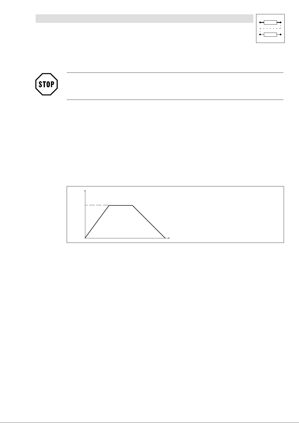
Function library
Positioning control
3.4.9 Travel profile generator and setpoints
l Traversing profile parameters can be changed via input POS−PARAM−RD even during a
positioning process.
Stop!
For the "Manual jog function with intermediate stop", POS−PARAM−RD has to be set = LOW.
Function
l Linear ramps (L profile) ( 3−59)
l S ramps (S profile) ( 3−60)
l Override (POS−V−OVERRID, POS−A−OVERRID) ( 3−62)
l New traversing profile parameters during positioning (POS−PARAM−RD) ( 3−58)
l Influence of precontrol values (POS−NOUT−GAIN, POS−MOUT−GAIN) ( 3−62)
l Target window (POS−WAITSTATE) ( 3−64)
l Virtual master (POS−PHI−SET) ( 3−65)
3.4.9.1 Linear ramps (L profile)
v
V T V E L
+ V T A C C
Fig. 3−22 Linear ramps (L profile)
l
The profile generator works on an optimum time base using the L profile, i.e. the target
position can be reached as quickly as possible with the acceleration and speed selected.
l The acceleration selected is effective immediately when the velocity is changed.
l Default setting: L profile.
- V T A C C
VTVEL =
+ VTACC =
− VTACC =
t
Traversing speed
Acceleration
Deceleration
9300POS026
l
EDSVS9332P−EXT DE 2.0
3−59
Page 88
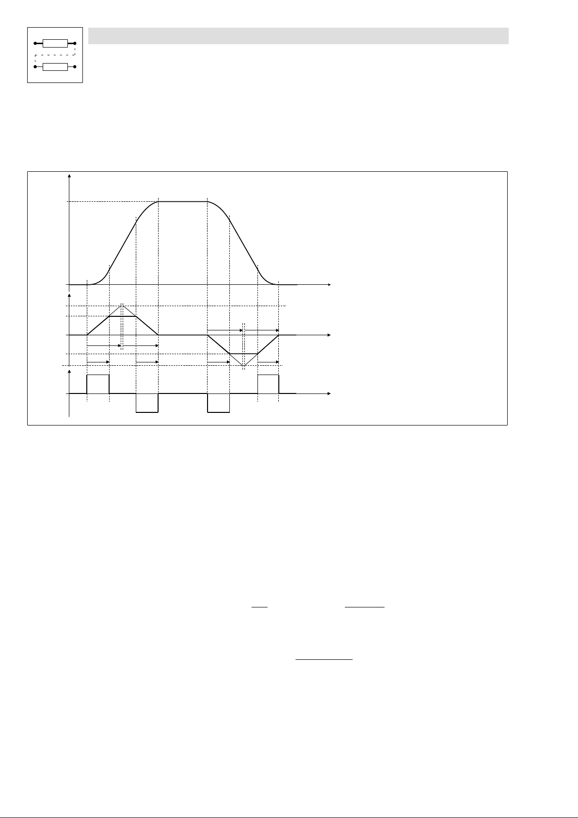
Function library
Positioning control
3.4.9 Travel profile generator and setpoints
3.4.9.2 S−shaped ramps (S profile)
Purpose
Protection from damage of the drive components by reducing the jerk during acceleration and
deceleration.
V
VTVEL
a
a
max
VTACC
C1256 C1256
VTACC
a
max
tr tr
Ruck
1234 5 6 7 89
Fig. 3−23 S−shaped ramps (S profile)
1. Standstill 6. Deceleration with set jerk
2. Deceleration with set jerk 7. Deceleration with VTACC
3. Acceleration with VTACC 8. Reduce deceleration with set jerk
4. Reduce acceleration with set jerk 9. Drive in targetposition
5. Traversing with VTVEL
With the S profile acceleration and deceleration processes are started smoothly. The defined
l
acceleration is only reached at the end of the jerk time.
– A slower acceleration always leads to a longer positioning time − compared to the
time−optimised L profile.
– Set jerk time (T
Tr corresponds to the time when the max. acceleration a−max (C1250) is reached. The actual
jerk time tr decreases according to the actual accelerationa:
– Reducing the jerk or increasing the jerk time (t
POS−JERK−RED" (default setting 100%).
) via C1256.
r
tr + Tr
C1256 C1256
tr
a
a
max
t
+ tr
r(RED)
t
t
tr
t
³ tr + C1256
) can be set via the input
r(RED)
100%
POS−JERK−RED
VTVEL =
+ VTACC =
− VTACC =
VTACC[%]
100%
Traversing speed
Acceleration
Deceleration
9300pos002
3−60
EDSVS9332P−EXT DE 2.0
l
Page 89

Function library
Positioning control
3.4.9 Travel profile generator and setpoints
l The S profile must be activated before starting the positioning process.
l S profile is activated as follows:
Connect input POS−S−RAMPS" with 1−signal, e. g. assign FIXED1 directly or set
FCODE−471.B1 = 1 (default setting).
l With POS−PARAM−RD" you can switch between both profiles even during the positioning
process.
When changing from the L profile to the S profile during acceleration/deceleration, the S
profile starts with acceleration 0 all the same. The process is prolonged accordingly.
Tip!
l The jerk remains unchanged when the acceleration is changed.
– If a target position cannot be reached with these parameters (e. g. with TP positioning or
velocity changeover) the target position is overtravelled. Afterwards the drives changes its
direction of rotation and travels to the target position.
– If a positioning process with or without final speed (changeover of velocity) is followed by a
positioning process in opposite direction, the acceleration will be reduced to 0 before it is
built up in opposite direction.
l For the S−profile, the deceleration is automatically equated with the acceleration in the PS.
Inputs for the deceleration are not considered.
l Special feature when stopping in manual operation, homing, PS−CANCEL, program stop:
Stops are always realised with linear ramps!
Firmware version ³ 2.5:
Under C1259/1.../3 it is possible to change to S ramps for stopping.
Stopping with S ramp
The corresponding setting parameters for the S ramp can be found in the GDC under the following
menu: POS functions / S−ramps". This function can be set with code C1258.
When the S−ramp function is activated, the default settings of the controller cause the drive to be
stopped in the case of the following functions with linear ramp:
– Manual jog,
– Prg−stop,
– PS−CANCEL and
– Homing
With firmware version ³V2.5 the controller can be switched to stopping with S−ramp for the following
functions when the S−ramp function is activated:
– Manual jog (C1258/1),
– Prg−Stop (C1258/2),
– PS−CANCEL (C1258/3)
l
EDSVS9332P−EXT DE 2.0
3−61
Page 90
Function library
Positioning control
3.4.9 Travel profile generator and setpoints
3.4.9.3 Override
Purpose
l Dynamic change of the profile parameters (speed and acceleration).
Example: Setting the traversing speed depending on the master speed.
Function
l Dynamic adaptation of traversing and final speed (POS−V−OVERRID).
l Dynamic adaptation of acceleration and deceleration (POS−A−OVERRID).
l The override inputs are considered before each positioning process. With the input
POS−PARAM−RD this is also possible during the process (see chapter 3.4.9.4)
– The parameter values are reduced according to the % values at the override inputs.
l In manual operation the override inputs are always effective.
– Note: Only positive override values are effective, negative values will be evaluated as zero.
3.4.9.4 New traversing profile parameters during positioning (POS−PARAM−RD)
Purpose
l Change of the target position, speed or acceleration during positioning.
Function
l LOW−HIGH edge at POS−PARAM−RD immediately accepts − also while positioning is running −
new profile parameters from the VT variable tables.
Profile : Target position, traversing speed, acceleration, deceleration, final speed, V override, A
override, POS−S−RAMPS (limited).
– With a constant HIGH level: new profile parameters are accepted every 10 ms.
Tip!
Firmware version < 2.5: Not effective in stand−by operation.
Firmware version ³ 2.5: Also effective in stand−by operation.
3.4.9.5 Influence of precontrol values (POS−NOUT−GAIN, POS−MOUT−GAIN)
Purpose
l Reduction of the influence of precontrol on speed and torque controller.
Function
l Adaptation of the speed precontrol (POS−NOUT) to the speed controller (MCTRL−N−SET)
(POS−NOUT−GAIN, default setting: 100%)
3−62
l Adaptation of the torque precontrol (POS−MOUT) to the torque controller
(POS−MOUT−GAIN, default setting: switched off)
l The precontrol values are reduced according to the % values at the inputs.
Tip!
With dynamic positioning processes, a reduction of the speed precontrol (e.g. to 95%) can be
advantageous for the travelling performance towards the target position.
EDSVS9332P−EXT DE 2.0
l
Page 91
Function library
Positioning control
3.4.9 Travel profile generator and setpoints
3.4.9.6 "Target−reached" message (POS−IN−TARGET)
Purpose
Messaging the termination of positioning.
Function
l A positioning process is terminated when the position setpoint POS−SETPOS of the profile
generator has reached the target position POS−TARGET ("setpoint−based").
l POS−IN−TARGET=HIGH messages that the position setpoint POS−SETPOS has reached the
target position POS−TARGET.
l The other program functions are only processed further when POS−IN−TARGET = HIGH.
Tip!
Because of mains failure, the drive may not be in the indicated position, although the message
POS−IN−TARGET was indicated.
l
EDSVS9332P−EXT DE 2.0
3−63
Page 92
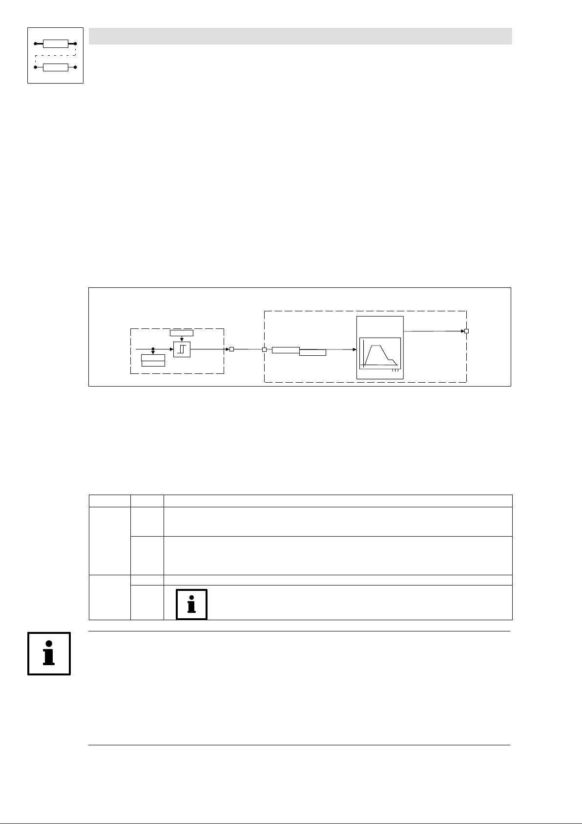
Function library
Positioning control
3.4.9 Travel profile generator and setpoints
3.4.9.7 Target window (POS−WAITSTATE)
Purpose
Particularly high demands on the accuracy for reaching the target position (message: Target
reached).
Function
Via the input POS−WAITSTATE the "Target reached" message can be ( 3−63) delayed until the
pending following error has been compensated and the drive has reached the target with sufficient
accuracy (target window).
The program will not be processed until
l the position setpoint POS−SETPOS has reached the target and
l the input POS−WAITSTATE=LOW.
POS
MONIT
C1218/2
POS−POUT
C1220/4
C1221/4
Fig. 3−24 Connect output MONIT−P15 with input POS−WAITSTATE
MONIT−P15
C1360/22
By the interconnection of the function blocks shown in Fig. 3−24 the continuation of the program is
delayed within a narrow target window (POS−WAITSTATE = HIGH) until the actual position value is
actually in the target window. For this the target window is preselected in a very narrow manner in
C1218/2 (second following error tolerance). In order to be able to continue the program processing
later on, the system deviation between the setpoint and the actual value, which is referred to as the
following error, must be smaller than the target window defined before. The output MONIT−P15 also
switches if monitoring P15 is switched off.
Output Level Description
POS−WAITST
ATE
MONIT−P15
HIGH POS−IN−TARGET is not yet set since the current positioning is still running. The functions of the next PS are not carried
out yet.
During homing, the function is not effective.
LOW Continuation of the program:
The program is only continued if the difference between actual value and setpoint is compensated such that the
difference is within the permissible following error tolerance.
Under code C1218/2 you can enter a following error with less tolerance.
HIGH Display when the current following error is greater than the target window.
The output MONIT−P15 will be switched even if the second following error monitoring is switched
off.
POS−WAITSTATE
C1361/22
CTRL
POS−IN−TARGET
3−64
Tip!
l In practice, the "Target window" function only has to be used for particularly high demands
with regard to the accuracy of the target achievement. According to experience, in most
applications the standard "Target reached" message, which is derived from the setpoint of the
profile generator, is sufficient.
l During homing the POS−WAITSTATE function is not effective. The end of a reference run is
always indicated by the homing status (POS−REF−OK).
EDSVS9332P−EXT DE 2.0
l
Page 93
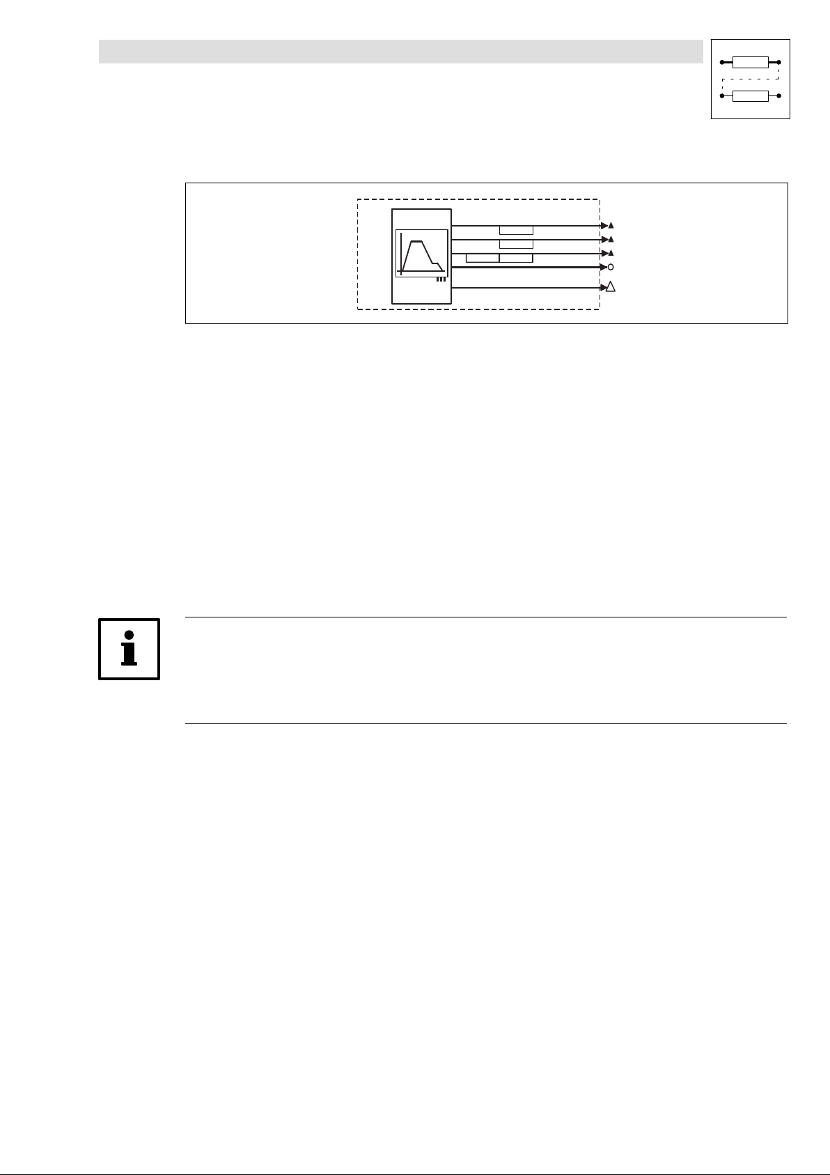
Function library
Positioning control
3.4.9 Travel profile generator and setpoints
3.4.9.8 Virtual master (output POS−PHI−SET)
POS
Speed profiler
(Values following the profile)
C1220/2
C1255/1
C1245/1
C1221/2
POS-ASET
POS-VSET
POS-SETPOS
POS-NSET
(Virtual master function)
POS-PHI-SET
9300POS038
Purpose
l Phase− and speed−synchronous traversing of two or several drives.
Function
l Definition of virtual master":
Via the required phase difference output (POS−PHI−SET) of the master drive the master drive
itself and the "slave" drives are positioned in parallel.
This does not lead to any reactions between the drives and no offset in positioning occurs in
contrast to connecting the slave drives via the actual phase difference output
(MCTRL−PHI−ACT).
l POS−PHI−SET is transmitted to the slave drives through digital frequency connection (DFOUT,
DFIN, DFSET).
l A connection via system bus (CAN) is possible.
– Advantage of clocked drives:
For improving the dynamic features a speed precontrol can be transmitted in addition.
Tip!
With system bus coupling (CAN) the controllers must be synchronised, otherwise position
information may get lost. The synchronisation is realised in the slave drives via the SYNC function
block. In the master drive the "CAN sync telegram" must be generated.
l
EDSVS9332P−EXT DE 2.0
3−65
Page 94
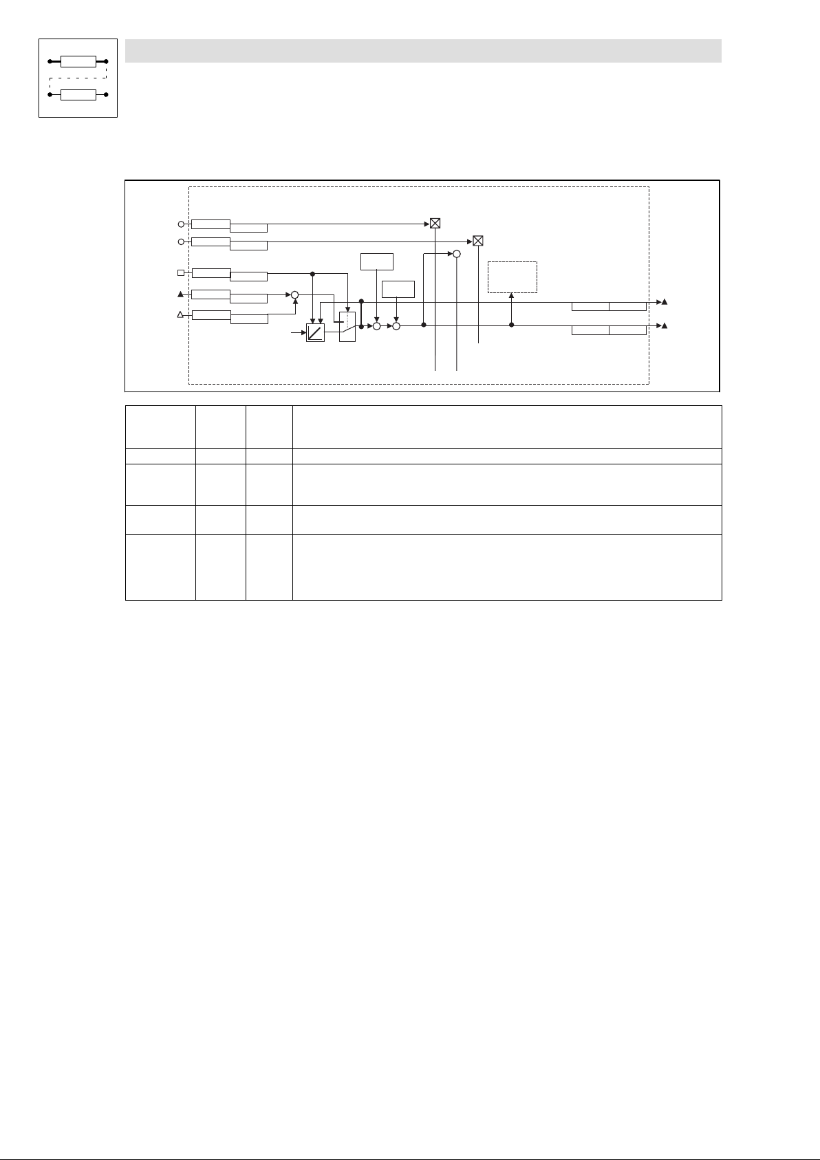
Function library
Positioning control
3.4.9 Travel profile generator and setpoints
3.4.9.9 Setting the actual position value (POS−ABS−SET)
C 1 3 6 2 / 7
C 1 3 6 3 / 7
P O S - N O U T - G A I N
C 1 3 6 2 / 5
C 1 3 6 3 / 5
C 1 3 6 0 / 2 1
P O S - A B S - S E T
C 1 3 6 1 / 2 1
P O S - A B S - I N
C 1 3 6 4 / 2
C 1 3 6 5 / 2
P O S - P H I - A D D
C 1 3 6 6 / 1
C 1 3 6 7 / 1
M C T R L - P H I - A C T
( f e e d b a c k s e l e c t e d u n d e r C 4 9 0 )
( I n f l u e n c e o f f e e d f o r w a r d v a l u e s )
+
+
S e t
1
0
( G e n e r a t i o n o f a c t u a l p o s i t i o n )
h o m e p o s i t i o n
C 1 2 2 7
C 1 2 2 1 / 8
h o m e o f f s e t
C 1 2 2 1 / 7
+++
C 1 2 2 5
-
P O S
+
-
P O S - T P
( T o u c h P r o b e )
P O S - A B S - V A L
C 1 2 2 1 / 1 6C 1 2 2 0 / 1 6
P O S - A C T P O S
C 1 2 2 1 / 3C 1 2 2 0 / 3
9300POS035
POS−ABS−IN C1365/2 C1364/2 Input for external actual position value, e. g. when using an absolute value encoder with a CAN
interface.
(see Absolute encoders via system bus" 3−40)
POS−ABS−SET Changeover (position encoder C490) / (ABS−IN)
POS−ABS−VAL C1220/16
C1221/16
Display as actual position POS−ACTPOS, but without considering setpoint position polarity (C1206),
actual position (C1206), actual home position (display C1220/8) and actual reference dimension offset
(display C1220/7).
POS−ACTPOS C1220/3
C1221/3
− Actual position; position relating to real zero
For rating see formula 1
POS−PHI−ADD C1367/1 C1366/1 Phase difference signal is added to POS−ABS−IN.
Function: With POS−ABS−SET= HIGH the actual position is set to the value POS−ABS−IN. Encoder
increments that have arrived in the setting cycle are not considered in the default. If required, the
encoder change can be connected in the setting cycle; the signal MCTRL−PHI−ACT must be linked with
the input POS−PHI−ADD.
Home position
HIGH = Phase value at POS−ABS−IN is read in for actual position value generation (POS−ACTPOS).
The following values are considered when POS−ACTPOS is generated:
– Position setpoint polarity (C1206)
– Actual position value polarity (C1208)
– Actual home position (display C1220/8)
– Actual reference dimension offset (display C1220/7).
3−66
EDSVS9332P−EXT DE 2.0
l
Page 95
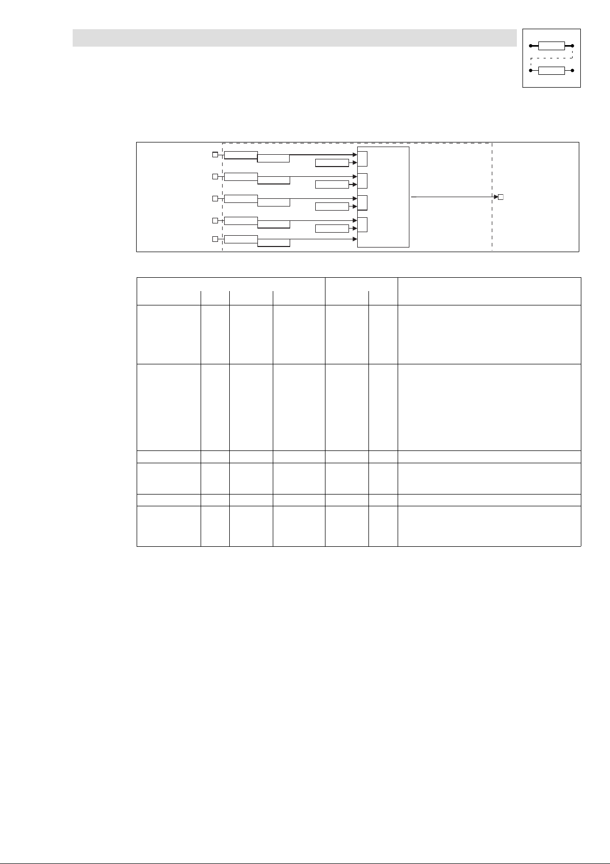
Function library
Positioning control
3.4.10 Manual operation
3.4.10 Manual operation
C 1 3 6 0 / 6
C 1 3 6 0 / 7
C 1 3 6 0 / 8
C 1 3 6 0 / 9
C 1 3 6 0 / 1 0
Fig. 3−25 Manual jog (part of the POS function block)
Signal
Designation Type DIS DIS format CFG List
POS−MANUAL d C1361/6 bin C1360/6 2 Changeover Manual jog / program operation
POS−MANU−NEG d C1361/7 bin C1360/7 2 HIGH = drive travels with v_manual (C1243) in negative
POS−MANU−POS d C1361/8 bin C1360/8 2 Like POS−MANU−NEG, but in positive direction
POS−MANU−REF d C1361/9 bin C1360/9 2 LOW−HIGH signal = Start manual homing
POS−REF−MARK d C1361/10 bin C1360/10 2 Homing switch
POS−MANU−ACT d − − − − HIGH = manual operation active, no program operation
P O S - M A N U A L
C 1 3 6 1 / 6
P O S - M A N U - N E G
C 1 3 6 1 / 7
P O S - M A N U - P O S
C 1 3 6 1 / 8
P O S - M A N U - R E F
C 1 3 6 1 / 9
P O S - R E F - M A R K
C 1 3 6 1 / 1 0
C 1 2 8 0 . B 4
C 1 2 8 0 . B 6
C 1 2 8 0 . B 5
C 1 2 8 0 . B 7
1
³
1
³
M A N U A L
1
³
+
H O M I N G
P O S - M A N U - A C T
C T R L
1
³
Source Note
HIGH = manual operation; if necessary, running program
is interrupted. If necessary, drive is decelerated to
standstill with a−manual (C1252) and the influence of
POS−A−OVERRID.
LOW = Program operation
direction. Acceleration with a−manual (C1252). The
override inputs POS−V−OVERRID and POS−A−OVERRID have
influence.
LOW = drive is stopped with a−manual (C1252). The
override inputs POS−V−OVERRID and POS−A−OVERRID have
influence.
Note: POS−MANU−REF has priority. When −NEG and −POS
are triggered simultaneously the drive stops.
HIGH level required for the time of homing
(see 3.4.10.3 "Manual referencing")
Note: Signal will not be updated when the controller is
inhibited (DCTRL−CINH = HIGH) or quick stop
(MCTRL−QSP−OUT = HIGH) is set
9300POS029
l
EDSVS9332P−EXT DE 2.0
3−67
Page 96
Function library
Positioning control
3.4.10 Manual operation
Function
l Manual jog without intermediate stop ( 3−68)
l Manual jog with intermediate stop ( 3−69)
l Manual homing ( 3−69)
3.4.10.1 Manual positioning
l Set manual jog mode to Manual jog without intermediate stop" (C1260 = 0)
l Activating manual operation: Activating manual operation:
POS−MANUAL = HIGH and/or
C1280/B4 = 1 (manual jog" in the "Control" GDC dialog)
l Manual control in positive direction:
POS−MANU−POS = HIGH and/or
C1280/B5 = 1 (manual positive" in the Control" GDC dialog).
l Manual control in negative direction:
POS−MANU−NEG = HIGH and/or
C1280/B6 = 1 (manual negative" in the "Control" GDC dialog).
l The drive brakes to standstill if none of the manual functions is activated or both of them.
l Manual positioning speed adjustable under C1243.
l Manual acceleration/deceleration adjustable under C1252.
l The override inputs POS−V−OVERRIDE and POS−A−OVERRIDE are always effective
l The drive stops when a travel range limit switch is reached. Fault messages P01 or P02 are
activated.
Tip!
l Assigned travel range limit switches can be left again in manual operation in direction of the
travel range. The fault must be reset before.
l In manual operation the drive stops with linear ramps (L−profile). From software version 2.5 the
ramps can be set with C1256. ( 3−60)
The following conditions must be met to ensure that the drive can be traversed manually:
1. The drive must be enabled (DCTRL−CINH =0),
2. The QSP function must not be activated (MCTRL−QSP−OUT=0),
3. Manual homing must be inactive:
POS−MANU−REF = LOW and
C1280/B7 = 0 (Manual homing" in the Control" GDC dialog),
3−68
4. Only one direction is to be selected.
If the positive and negative direction are activated at the same time, the drive is braked to
standstill.
EDSVS9332P−EXT DE 2.0
l
Page 97

Function library
Positioning control
3.4.10 Manual operation
3.4.10.2 Manual jog with intermediate stop
Purpose
l During manual positioning, the drive is to stop at defined target positions (intermediate stops).
Activating this function
l Set manual jog mode to Manual jog with intermediate stop" (C1260 = 1).
l Set input POS−PARAM−RD = LOW.
l Carry out the next steps like in chapter "Manual jog". ( 3−68)
l The intermediate stop positions are defined by selecting the target positions from the VTPOS
variable table. Up to 16 target positions can be selected via C2161/1 to C1261/16.
(GDC menu: Positioning functions/manual jog")
l The drive travels to the next target position and stops there. In order to continue, the control
signal for "manual positive" or "manual negative" must be reset and then set again.
The drive immediately brakes to standstill if the control signal is reset before
target position.
reaching the next
3.4.10.3 Manual homing
Purpose
Example: Homing during commissioning.
Activating the function
The homing parameters set apply to manual homing ( 3−46)
Procedure:
1. Activate manual operation
– Set POS−MANUAL = HIGH and/or
C1280/B4 = 1 (Activate the Manual jog" option field in the "Control" GDC dialog).
2. Start manual homing
– Rising edge at POS−MANU−REF or
rising edge at C1280/B7 (Activate the Manual homing" option field in the "Control" GDC
dialog).
The signal for manual referencing has to be pending until the end of the homing process,
otherwise the process is interrupted.
– A restart is effected with a rising edge again.
– For "Manual jog with intermediate stop", set the input POS−PARAM−RD = LOW.
Tip!
l Manual homing has priority over manual jog, that means the signals for manual jog have no
effect when manual homing is activated by a control signal.
l
l For manual homing the following conditions have to be met:
– The drive must be enabled (DCTRL−CINH = 0).
– The QSP function must not be activated (MCTRL−QSP−OUT = 0).
– The interval between "Activate manual operation" and a rising edge for "Start manual
homing" at least has to be 1 ms (1 x cycle time).
EDSVS9332P−EXT DE 2.0
3−69
Page 98
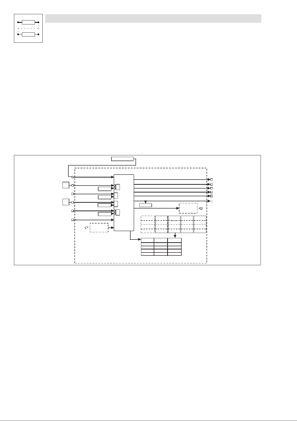
Function library
Positioning control
3.4.11 Program operation
3.4.11 Program operation
Purpose
Positioning programs for automatic operation of the application can run during program operation.
Function
l Program control ( 3−70)
l Variable tables (VT) ( 3−75)
l Program blocks (PS) ( 3−76)
3.4.11.1 Program control
Purpose
The program control offers the possibility to influence program processing by a higher−level control
(e.g. PLC) or directly from the operator’s panel.
FCODE-C1211
(1)
E3
E5
POS-START-PS
POS-PRG-START
POS-PRG-STOP
POS-PRG-RESET
POS-PS-CANCEL
POS-STDBY-STP
POS-PFI
C1280.B0
C1280.B1
C1280.B2
C1280.B3
Program
control
³
1
1
³
1
³
1
³
C1212
Variable tables (VT)
VTPOS
VTVEL
C1301/1
C1302/1
...
...
C1301/104
C1302/34
Program sets (PS)
C1311/1
C1312/1
C1349/1
PS1
... ...
...
...
...
...
VTACC
C1303/1
...
C1303/34
PS32
C1311/32
C1312/32
...
C1349/32
Fig. 3−26 Functionality of PS, VT, PFI and PFO (excerpt from the POS function block)
Starting the program (PRG−START)
l The beginning of the program to be started is determined by the FB input POS−START−PS".
In the standard configurations this input is connected with FCODE C1211. In the default
setting the program starts with PS01.
l Starting the positioning program with
− LOW−HIGH edge at POS−PRG−START or
− C1280.B0 = 0 / 1 edge (Program start" in the GDC dialog "Control").
POS
POS-RUNNING
POS-STARTED
POS-STOPPED
POS-ENDED
POS-RESETED
POS-ACT-PS-NO
POS-PFO
VTTIME
VTPCS
C1305/1
C1304/1
...
C1305/34
C1304/34
...
9300POS031
3−70
EDSVS9332P−EXT DE 2.0
l
Page 99

Function library
Positioning control
3.4.11 Program operation
Tip!
l The program processing is continued to the "Program end" even if the start signal is reset
immediately.
l If the start signal is still applied at "program end" the program will be restarted automatically
every time.
l A new edge at POS−PRG−START is required after interrupting the program processing (e.g. by
controller inhibit) or by a fault message.
Afterwards the program is continued from the same position (status display: C1283=15).
The start signal will only be accepted in program operation and when the controller is enabled.
The controller is enabled if
1. the power stage is supplied (DCTRL−RDY=1),
2. no fault applies (DCTRL−TRIP=0, DCTRL−FAIL−QSP=0),
3. the control enable signal is applied (DCTRL−CINH=0)
4. quick stop (QSP) is not activated (MCTRL−QSP−OUT=0)
5. manual operation is not activated (POS−MANUAL=0, C1280.B4=0)
6. program reset is not activated (POS−PRG−RESET=0, C1280.B2=0)
Stopping the program (PRG_STOP)
l POS−PRG−STOP = HIGH or C1280.B1 = 1 (Program stop" in the GDC dialog "Control").
– The signal "program stop" interrupts the program processing and the running positioning
process. The drive is stopped with the current delay of the program set (no influence of
POS−A−OVERRID).
l POS−PRG−STOP = LOW and C1280.B1 = 0 (Program stop" in the GDC dialog "Control").
– The program is continued from the same position when Program stop"=LOW. The
positioning process is finished with the current profile parameters of the PS.
l
EDSVS9332P−EXT DE 2.0
3−71
Page 100
Function library
Positioning control
3.4.11 Program operation
Resetting the program (PRG−RESET)
l POS−PRG−RESET = HIGH or C1280.B2 = 0 (Program reset" in the GDC dialog "Control").
l When a program is reset,
– the drive will be stopped with a−max (C1250) (no influence of POS−A−OVERRID)
– the program will be interrupted
– Program end" will be set
– the piece counter will be set to zero
– the program function outputs (PFO) will be reset
– the touch probe inputs used by the program will be disabled"
– and if necessary, stand−by operation will be cancelled.
Tip!
The signal for resetting the program is also accepted and saved in the inhibited state. The program
reset will only be executed in the released state (see notes under "starting the program").
Cancelling the current PS (PS−CANCEL)
l LOW−HIGH signal at POS−PS−CANCEL or C1280.B3 = 0 / 1 signal.
– The drive will be decelerated to standstill with the separately adjustable delay a−cancel"
(C1253).
– The program will be continued in the PS selected (C1333; JMP−TP−PS).
3−72
EDSVS9332P−EXT DE 2.0
l
 Loading...