

Page 1
EDB2131UB
Show/Hide Bookmarks
00408822
Operating Instructions
PROFIBUS-DP
24VDC
+-
2131
Fieldbus module type 2131
PROFIBUS
Page 2

These Operating Instructions are valid for fieldbus modules with the following nameplate data:
Show/Hide Bookmarks
2131 IB. 0x. 0x. PROFIBU S
Together with the unit series as from thenameplate data:
820X E. 2x. 1x. (8201- 8204)
820X E./C. 2x. 1x. Vxxx (8201- 8204)
821X E. 2x. 2x. (8211- 8218)
821X E./C. 2x. 2x. Vxxx (8211- 8218)
822X E. 1x. 1x. (8221- 8225)
822X E. 1x. 1x. Vxxx (8221- 8227)
824X E. 1x. 1x. (8241- 8246)
824X E./C. 1x. 1x. Vxxx (8241- 8246)
82EV V A 0x 8200 v ector
82EV 1x 0x 8200 vector
93XX E. 2x. 1x. (9321 - 9333)
93XX E./C. 2x. 1x. Vxxx (9321- 9333)
Type
Design:
E = Enclosure I P20
IB = Module
Hardware level and index
Softw are levelandind ex
Variant
Explanation
Important:
TheseOperatingInstructionsareonlyvalidincombinationwiththeOperatingInstructions of the
controller 82XX, 8200 vector or 93XX.
.
1996 Lenze GmbH&Co KG
Without written approval of Lenze Lenze GmbH&Co KG no part of these Instructions must be copiedor given to third parties.
Allindicationsgivenin these Operating instructions havebeen selected carefully andcomply withthe hardware and software described. Nevertheless,
deviation scannot beruled ou t .We donottake anyresponsibility orliabilityfordamageswhichmightpossiblyoccur. Requ ired correctionswill be madein
the follo w ing editions.
Version 1.0 06/99
Page 3

Contents
Show/Hide Bookmarks
1 Preface and general information 1-1...........................................
1.1 How to use these Operating Instructions 1-1................................................
1.1.1 T erminology used 1-1.........................................................
1.1.2 What is new? 1-1............................................................
1.2 Scope of supply 1-1..................................................................
1.2.1 Legalregulations 1-2..........................................................
2 Safety information 2-1......................................................
2.1 Persons responsible for safety 2-1.......................................................
2.2 Generalsafety information 2-1..........................................................
2.3 Layout of the safety information 2-2......................................................
3 Technical data 3-1.........................................................
3.1 Featur es of the 2131 fieldbus module 3-1..................................................
3.2 General data / application conditions 3-1..................................................
3.3 Rated data 3-2......................................................................
3.4 Dimensions 3-2.....................................................................
3.5 P r o toco l data 3-2....................................................................
3.6 Communication times 3-3.............................................................
3.6.1 Data-transfer time 3-3.........................................................
3.6.2 Processing time in the controller 3-3..............................................
3.6.3 Number of participants 3-4.....................................................
4 Installation 4-1............................................................
4.1 Connections of the fieldbus module 2131 4-1...............................................
4.1.1 Ov erview 4-1................................................................
4.1.2 9 pole SubD pin connector 4-2...................................................
4.1.3 Plug-in terminal for 2 pole male plug (external supply voltage) 4-2........................
4.2 Mechanical installation 4-3.............................................................
4.3 Electrical installation 4-3..............................................................
4.3.1 V oltage supply 4-3............................................................
4.3.2 Wiring to a host 4-4...........................................................
5 Commissioning 5-1........................................................
5.1 Configuration of the host system for communication with the 2131 fieldbus module. 5-1...............
5.1.1 Settings with COM -ET200 DOS 5-1................................................
5.1.2 Settings with COM -ET200 W IN 5-1................................................
5.1.3 Programexample 5-2.........................................................
5.2 Com missioningof the 2131 fieldbus module 5-2.............................................
5.2.1 Dr ive control via PROFIBUS 5-2..................................................
5.2.2 Enable controller 5-3..........................................................
5.3 Diagnostics 5-4.....................................................................
5.4 Sp ecial features with 82XX ,8200 vector and93XX 5-4........................................
BA2131EN
i
Page 4

Contents
Show/Hide Bookmarks
6 Parame ter setting 6-1......................................................
6.1 Parameters 6-1.....................................................................
6.1.1 Lenze parameters 6-1.........................................................
6.1.2 DRIVECOM parameters 6-2.....................................................
6.1.3 Op erating mode C0001 6-3.....................................................
6.1.4 Bus address/station address 6-3.................................................
6.1.5 Baud rate 6-4...............................................................
6.1.6 Master settings 6-4...........................................................
6.2 PROFIBUS-DP configuration 6-4.........................................................
6.3 PROFIBUS-DP parameter-setting channel 6-5...............................................
6.3.1 Structure ofthe DPparameter-settingchannel 6-5....................................
6.3.2 Parameter communicationwiththe controller 6-7.....................................
6.3.3 Example1: Write parameter 6-8..................................................
6.3.4 Example2: Write parameter 6-9..................................................
6.4 P r o cess data 6-9....................................................................
6.4.1 P r o cess-data assign ments for 82XX 6-10............................................
6.4.2 P r o cess-data assign ment for 8200 vector 6-10........................................
6.4.3 Process-data assignment for 93X X 6-11.............................................
6.5 Co ntroller status 6-13.................................................................
6.5.1 Standard unit control 6-13.......................................................
6.5.2 DRI V ECOM unit control 6-14......................................................
6.5.3 Control word 6-17.............................................................
6.5.4 Status word 6-20..............................................................
6.6 Lenze-specificparameters 6-22..........................................................
6.6.1 On ly82XX: Lenze param eter Operating Mod e (L-C0001) 6-22.............................
6.6.2 Param eter L-C0142 6-22........................................................
7 Troubleshooting and fault elimination 7-1.......................................
7.1 Controller is inhibited 7-2..............................................................
7.2 Check PROFIBUS 7-4.................................................................
7.3 Activate the fieldbus module 7-5.........................................................
7.4 Fault reset (TRIP ) 7-6.................................................................
8 Appendix 8-1.............................................................
8.1 A ccessories 8-1.....................................................................
8.2 List of abbreviations 8-2...............................................................
8.3 Glossary 8-3.......................................................................
8.4 Tableofkeywords 8-4................................................................
ii
BA2131EN
Page 5

Preface and general inf ormation
o
rforv
o
y
)Contr
o
(LA
R00A
A
)
liabilityfordeficienciesclaimed
subse
quently
a)ControllermasterfiletoDINE19245part3(
L_AR00A
A.GSD
)
pgy
S
imat
ic-S5COM-ET200V5.X(LE00AAA
X.200
)
Show/Hide Bookmarks
1 Preface and general information
1.1 How to use these Operating Instructions
l
These Operating Instructions are intended for safety-relevant operations on and with the 2131
fieldbus module. They contain safety information which must be observed.
l
All personnel working on and with the 2131 fieldbus module must have these Operating
Instructions available and observe the information and notes relevant for them.
l
The Operating Instructions must always be complete and perfectly readable.
TheseOperating Instructionsinform about the mostimportant technicaldata and the installationof
the 2131 fieldbus module. Theyare only valid in combination with theOperating Instructions of the
corresponding controller.
1.1.1 Terminology used
Controller In the following, the term ”controller” is used for ”93XX servo inverters” or ”82XX frequeny inverters”.
Drive system In the following, the term ”drive system” is used for drive systems with fieldbus modules or other Lenze drive
Fieldbus module In the following text, the term ”fieldbus module” is used for the fieldbus module type 2131 PROFIBU S .
Cxxx/y Sub code y of code Cxxx(z.B. C0410/3 = subcod e 3 of code C0410)
L-Cxxx/y Lenze code
Xk/y Terminal stripXk/termin aly (z.B. X 3 /2 8= termin al28 on terminal stripX3)
(xx-yyy) Crossreference (chapter - page)
1.1.2 What is new?
Ident. no. Edition of Important Contents
394 179 27/01/1997 Format change to DINA4
408822 01/06/1999 r ep laces 394 179
1.2 Scope of supply
Scope of supply Important
l
1 2131 fieldbus module with housing (enclosure IP20)
l
1M3fixingscrew
l
1two-pole male connect
l
1 diskette with:
–
–a
– b)Con troller type files for
llermasterfile toDIN E 19245part3
Simatic-S5 COM-ET 200V4.X(LE00A ATD.200)
components.
ltage suppl
l
Adaptation to 8200 vector (all chapters)
Afterthe delivered received,check immediately whetherthe items
supplied match the accompanying papers. Lenze does not accept any
Claim
l
.GS D
visible transport damage immediately to the forwarder
l
visible deficiencies/incompleteness immediately to your Lenze
representative.
.
BA2131EN
– c)Example program for Simatic-S5 (2130IB ST.S 5D)
l
1 Short Instructions
1-1
Page 6
Preface and general inf ormation
g
p
Show/Hide Bookmarks
1.2.1 Legal regulations
Labelling
Application as
directed
Liability
Warranty
Disposal
Nameplate CE mark Manufacturer
Lenze 2131 fieldbus modules are
unambiguously identified by their nameplates.
2131 fie l dbus module
l
Operate the fieldbus module only under the conditions prescribed in these Operating Instructions.
l
The fieldbus module is an additional module and can be optionally attached to the Lenze controller series 820X, 821X, 822X, 8200 vector
and 93XX. The 2131 fieldbus module links these Lenze controllers with the standardized serial communication system PROFIBUS-DP .
l
The fieldbus module must be attached and electrically connected so that it complies with its function and does not cause any hazards when
attached andoperated as instruc ted.
l
Observe all notes given in chapter „Safety information“
l
Please observe all information given in these Operating Instructions.This means:
– Read these Operating Instructions carefully before you start to work with the system.
– These Operating Instructions must always be available during operation of the fieldbus module.
Any other use shall be deemed inappropriate!
l
The information, data, and notes in these instructions met the state of the art at the time of printing. Claims referring to drive systems
which have already been supplied cannot be derived from the information, illustrations, anddescriptionsgiven in these Operating
Instructions.
l
The specifications, processes, and circuitry described in these Operating Instructions are for guidance only and must be adapted to your
own specific application. Lenze does not take responsibility for the suitabilityof the processand circuit proposals.
l
The indications given in these Operating Instructions describe the features of the product without warranting them.
l
Lenze doesnot accept any liabilityfor damag eandoperatinginterference causedby:
– disregarding these Instructions
– unauthorized modifications to the controller
– operatingerrors
– improper working on and with the controller
l
W arranty conditions: see Sales and Delivery Conditions of Lenze GmbH &Co KG.
l
Warranty claimsmust be made to Lenze immediatelyafter detectingthe deficiency orfault.
l
The warranty is vo idin all cases where liability claim scannot be made.
Material recycle dispose
Metal
Plastic
Assembled PCBs Short Instructions/Operating Instructions
Conforms to the EC Low Voltage Directive Lenze GmbH &Co KG
.
2-1)
(
-
-
-
P o stfach101352
D-31763 Hameln
-
-
-
1-2
BA2131EN
Page 7

Safety information
Show/Hide Bookmarks
2 Safety information
2.1 Persons respon sible for safety
Operator
l
An operator is any natural or legal person who uses the drive system or on behalf of whom the drive system is used.
l
The operator or his safety personnel is obliged
– to ensure the compliance with all relevant regulations, instructions and legislation.
– to ensure that onlyskilled personnel works on and with the2102I Bfieldbus module.
– to ensure that the personnel has the Operating Instructions available for all corresponding works.
– to ensure that all unqualified personnel are prohibited from working on and with the drive system.
Qualified personnel
Qualified personnel are persons who - because of their education, experience, instructions, and knowledge about corresponding standards and regulations, rules for
the prevention of accidents, and operating conditions - are authorized by the person responsible for the safety of the plant to perform the required actions and who are
able to recognize potential hazards.
(Definition for qualified personnel to VDE105 or IEC 364)
2.2 General safety information
l
These safety notes do claim to be complete. In case of questions and problems please contact your Lenze representative.
l
At the time of delivery the fieldbus module meets the state of the art and ensures basically safe operation.
l
The indications given in these Operating Instructions refer to the stated hardware and software versions of the fieldbus modules.
l
The fieldbus module is hazardous if:
– unqualified personnel works on and with the fieldbus module.
– the fieldbus module is used inappropriately.
l
The processing notes and circuit sections shown in these Operating Instructions are proposals which cannot be transferred to other applications without being
tested andchecked.
l
Ensure by appropriate measures that neither personal injury nor damage to property may occur in the event of failure of the fieldbus module.
l
The drive system must only be operated when no faults occur.
l
Retrofittings, modifications, or redesigns are basically prohibited.Lenze must be contacted in all cases.
l
The fieldbus module is electrical equipment intended for use in industrial high-power plants. The fieldbus module must be tightly screwed to the corresponding
controller duringoperation. Inaddition, all measuresdescribedin the OperatingInstructionsof theusedcontroller must be taken. Example: Fasten covers to ensure
protection against contact.
BA2131EN
2-1
Page 8
Safety information
Show/Hide Bookmarks
2.3 Layout of the safety information
l
All safety information has a uniform layout:
– The icon characterizes the type of danger.
– The signal word characterizes the severity of danger.
– The note text describes the danger and gives information how to prevent dangerous
situations.
Signal word
Note
Icons used Signalwords
Warning of
damage to
persons
Warning of
hazardous electrical
voltage
Danger! Warns of impending dangeU.
Consequences if disregarded:
Death orsevere injuries.
W arning of a general
danger
Warning of
damage to
material
Other notes Tip! This note designates general, useful notes.
Warning! Warns of potential,very hazardous situations.
Possible consequences if disregarded:
Death orsevere injuries.
Caution! Wa rns of potential,hazardous situations.
Possible consequences if disregarded:
Light or minor injuries.
Stop! Warns of potential damage to material.
Possible consequences if disregarded:
Damage of the controller/drive system or its environment
If you observe it, handling of the controller/drive system is made
easier.
.
2-2
BA2131EN
Page 9
3 Technical data
Show/Hide Bookmarks
3.1 Features of the 2131 fieldbus module
The 2131 fieldbus module has the following features:
l
Attachable additional module for Lenze controller series 820X, 821X, 8200 vector, 822X and
93XX
l
Slave interface module for the communication system PROFIBUS with the communication
profile PROFIBUS-DP (DIN19245 part 1 and part 3)
l
Automatic baud ratedetection
l
Baud rate between 9.6 kbaud and 12 Mbaud
l
Optionally 4or 6 byteproces data
l
Optional parameter-setting channel
l
Access to all Lenze parameters
l
Application profile: DRIVECOM Profil 20
Tec hnical data
3.2 General data / application conditions
Field Values
Order designation 33.2131IB
Communcation medium RS485
Network topology Line
Max. cable length 1200 m (depending on the desired baudrate and the cable type used)
PROFI BUSparticipants Slave
Communication profile PROFIBUS-D P(DIN19245 part 1 and part 3)
Drive profile DRI V ECOMprofile 20
Baud rate 9.6 kbit/s to 12000 kbit/s
Ambient temperature during operation: 0 to 50C
Permissible humidity Class 3K3 to EN50178 (w ithout condensation, average relative humidity 85%)
24-V-DC-
V oltage supply
Transport: -25 to 70
Storage: -25 to 55
l
820X / 8200 vector (ob serve chapter4.3.1): onlyextern al supply
l
821X / 822X / 8200 vector (ob serve chapter 4.3.1) / 93XX : internal or external supply
C
C
BA2131EN
3-1
Page 10

Tec hnical data
Show/Hide Bookmarks
3.3 Rated data
Field Values
Communication medium RS485
V oltage supply 24 VDC10 %; max 60 mA
Insulation voltage - bus systems:
to PE 50 VAC
for external supply (terminal 39/59) 0 V AC (no electrical isolation)
topower stage 820X: 270 VAC (s in gle basic insulation )
to the control terminals 820X: 0 V AC (no electrical isolation)
for the external bus systems 0 V AC (n oelectrical isolation)
Degree of pollution V DE 0110 part 2 pollu tio ndegree 2
821X: 270 VAC (s in gle basic insulation )
8200 vector: 270 V AC (double basic insulation)
822X: 270 VAC (double basic insulation)
93XX: 270 V AC (double basic insulation)
8200 vector (withinternal supply) :
0 V AC (n oelectrical isolation)
821X: 50 VAC
(E lectrical isolation)
8200 vector (withexternal supply):
100 VAC ( single basicinsulation)
822X: 270 VAC (s in gle basic insulation )
93XX: 270 V AC (single basic insulation )
3.4 Dimensions
62
75
2131
Fig. 3-1 Dimensions of the 2131 fieldbus module (all dimensions in mm)
3.5 Protocol data
Field Values
Maximum number of controllers without repeater: 31
Process-data words (PCD ) :
DP user-data length:
withrepeater: 125
l
2 words (32 bit)
l
3 words (48 bit)
l
2 words (32 bit)
l
3 words (48 bit)
l
Parameter-setting channel + 2 words (64 + 32 bit)
l
Parameter-setting channel + 3 words (64 + 48 bit)
18
28
3-2
BA2131EN
Page 11

3.6 Communication times
Show/Hide Bookmarks
The communication times depend on:
l
the data transfer time
l
theprocessing time in thecontroller
3.6.1 Data - transfer time
The data-transfer time depends on:
l
thebaud rate
l
theuser-datalength
You will find more information about the data-transfer time in the documentation for your host
system.
3.6.2 Processing time in the controller
Tec hnical data
Processing time 820X
For the 820X series several processing steps are required, which are processed cyclically.
A processing cycle consists of:
l
Writing of control word or setpoint, if the value has changed
l
Alternating reading of status word and actual value
l
Processing of parameter access if thereis a service
Ifthe timetolerances caused bythe cyclic readingof thestatus word/actual value aretoo large, the
alternating reading of thestatusword and the actual value can besuppressed. Thisiscontrolled by
the bit 15 (PE inhibit)of the DRIVECO M control word:
l
PEinhibit = 0:
Status and actual-value update active
l
PEinhibit = 1:
Status and actual value update not active
A suppression of the processing of parameter access is not necessary, since this is controlled by
theuser.
BA2131EN
3-3
Page 12
Tec hnical data
Show/Hide Bookmarks
In the following table you will find a list of the processing times:
Processing step Max. processing t ime in ms
PE-inhibit = 0 Tolerance PE-inhibit = 1 Tolerance
Read parameter 55 +48 55 +8
Control word or
setpoint
Control word and
setpoint
Write parameter 108 +32 - Status word and
actual value
Note:
A change of the setpoint signal results in writing the control word.
Processing time 821X / 8200 vector / 822X
The parameter data and process data are independent of each other.
l
Parameter data: 30 ms + 20 ms tolerance
l
Proces data: approx. 3ms + 2 ms tolerance
27 +48 27 +8
54 +56 54 +16
200 +40 200 -
Processing time 93XX
The parameter data and process data are independent of each other.
l
Parameter data: approx. 30 ms + 20 ms tolerance (typical)
– The processing time can be longer for some codes (see the 9300 Manual).
l
Process data: approx. 3 ms + 2 ms tolerance
3.6.3 Number of participants
l
Standard: 32 particpants (including host system)
l
With repeaters: 127 participants (including host systems)
You canbuild up line and tree topologies bymeans of repeaters. The maximum total expansion of
the bus system depends on:
l
the baud rate used
l
the number of repeaters
More detailed information can be obtained from thedocumentation for thecontrol system.
3-4
BA2131EN
Page 13

4 Installation
Show/Hide Bookmarks
4.1 Connections of the fieldbus modul e 2131
4.1.1 Overview
Installation
2131
8200 vector
82XX
Fig. 4-1 Controllers with fieldbus module 2131
2131
2131
93XX
BA2131EN
4-1
Page 14
Installation
5
8
7
6
Show/Hide Bookmarks
132
132
5
5
4
4
24 V D C
24 V D C
+ -
+ -
6
6
8
8
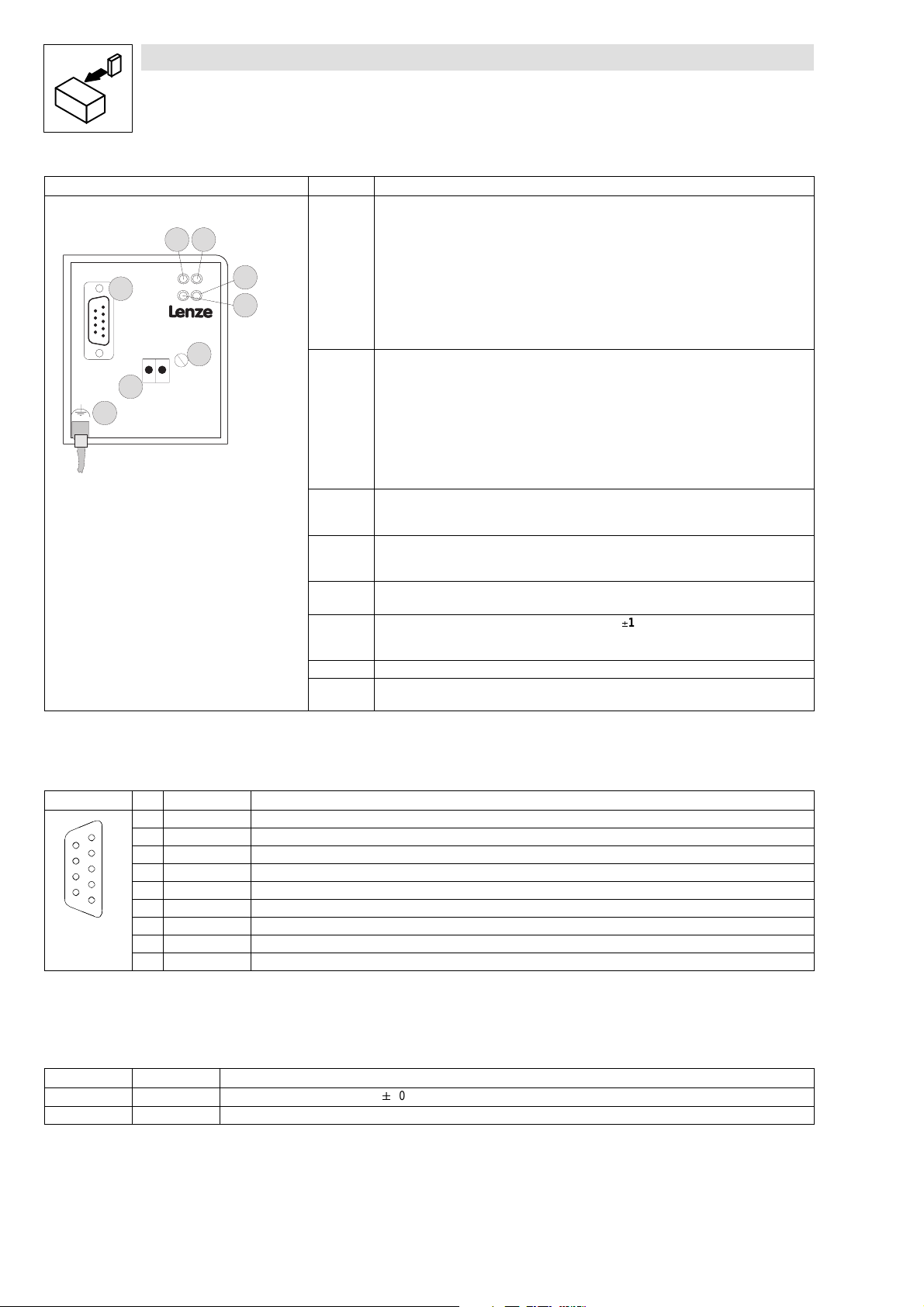
Fig. 4-2 2131 fieldbus module
7
7
2131
2131
2131pfb001
Pos. Name/Meaning
1 Green bus LED the voltage supply of the fieldbus module 2131
ON:
ON: 2131 fieldbus module is supplied with voltage and is connected to the controller .
OFF:
2131 fieldbus module is not supplied with voltage; controller or external voltage supply is
switched off.
BLINKIN G:
2131 fieldbus module is supplied with voltage but is not connected to the controller
(c ontroller is switchedoff, in initialization or not available) .
2 Yellow bus LED for the communication of the fieldbus module 2131
ON:
2131 fieldbus module is initialized but does not communicate with the PROFIBUS-DP from
the master.
OFF:
2131 fieldbus module is not initialized yet.
BLINKIN G:
PRO FIBUS-DP communication is active
3 Green drive LED (DRIVE)
Operating status of the 82XXor 93XX controllers. (See Operating Instructions of the
controller.)
4 Red drive LED (DRIVE)
Operating status of the 82XXor 93XX controllers. (See Operating Instructions of the
controller.)
5 PROFIBUS-DP connection
9 pole SubD pin connector (see chapter 4.1.2)
6 Connection for external voltage supply (24 V DC10%)
External voltage supply for the 2131 fieldbus module (see chapter4.1.3).
Always required for 820X ! For others as option.
7 Fix in gscrew for the 2131 fieldbus module
8 Only required for820X, 821X: additional PEscreen cable, whichavoids EMC related
communication interferences in especially noisy environments.
4.1.2 9 pole SubD pin connector
View Pin Name Explanation
1 PE Earth
2 free -
9
6
5
4
3 RxD/TxD-P Data transfer B
3
4 RTS R equest To Send
2
5 M5V2 Data reference potential
1
6 P5V2 5VDC
7 free 8 RxD/TxD-P Data transfer A
9 free -
1) Total current approx.60 mA
1)
4.1.3 Plug-in termina l for 2 pole male plug (external supply voltage)
Name Input/output Explanation
+ I nput External voltage supply +24 VDC/á10 %, 60 mA
- Input GND; reference for external supply
4-2
BA2131EN
Page 15

4.2 Mechanical installation
Show/Hide Bookmarks
l
Ifa keypad is attached to the front of the controller, removeit.
l
Plug the 2131 fieldbus module in the corresponding interface of the controller and fasten it
withthefixingscrew (
(4-2) ,Fig.4-2,pos.7).
4.3 Electrical installation
Note!
Thecommunciation of controllers820Xand 821X maybe interfered by electromagnetic radiation.
Installation
If necessary, use an additional PE screen cable (
4.3.1 Voltage supply
If required, supply the 2131 fieldbus module via the plug-in contacts 1/2 ( (
withaseparatevoltagesupply24VDC/10 %.
The821X,8200vector ,822x and 93XXshould always bedrivenwithout aseparate voltage supply.
The controllers 820X (8201¤8204)always require a separte voltage supply!
Use a separate supply unit for the external voltage supply (24 V)of the 2131 fieldbus module.
Use separate supply units for longer distances between the control cabinets.
The following chapter describes how to connect the 2131 fieldbus module to the bus system, see
chapter 4.3.2.
Note!
Internal voltage supply of the fieldbus module connected to a 8200 vector
Controllerswithan extended AIFinterface (front of the 8200 vector)can be internally supplied.The
part of the drawing highlighted with grey shows the jumper position.
In Lenze setting, the fieldbus module is not
For internal voltage supply, put the jumper in the position indicated below.
(4-2) ,Fig.4-2,pos.9).
internally supplied.
4-2) ,Fig.4-2,pos.6)
BA2131EN
Lenze setting
(only external voltage supply)
Internal voltage supply
4-3
Page 16

Installation
Show/Hide Bookmarks
4.3.2 Wiring t o a host
Warning!
An additional potential isolation must be installed if
l
a 820X, 821X or 8200 vector controller will be connected to a host
and
l
a safe electrical isolation (double basic insulation) to VDE0160 is required.
For this,you canuse an interfacemodulefor the host with an additional electricalisolation (seethe
corresponding manufacturer’s information).
For wiring, t he electrical isolation of t he supply voltage must be taken into ac count. The supply
voltage is assigned to the same potential as the data bus.
4-4
BA2131EN
Page 17

Wiring features:
Show/Hide Bookmarks
Features:
Communication medium RS485
Network topology without repeater: line
withrepeater: line ortree
Possible number of controllers without repeater: 32
withrepeater: 127
Max imum cable length 1200 m (d epen ding on the baud rate and the cable ty pe used)
Maximum baud rate 9.6-12000 kbit/s
The connection of the bus system PROF IBUS-DP is shown in the survey drawing. The required
accessories (e.g. connection cables) are listed in chapter 8.1.
Installation
82XX
Fig. 4-3 PROFIBUS with RS485 wiring (without repeater)
1Host
2 Bus-connector (
3Buscable(
4-6)
4-6)
93XX
8200 vector
2
3
1
BA2131EN
Wiring
Warning!
l
If the 2131 fieldbus module is no longer supplied with voltage, the bus system will continue
operation. However , the connected controller can no longer be accessed from the host.
l
If single bus participants are to be disconnected, it must be ensured that the bus terminators
at the physical cable ends remain active.
l
Only use cables which correspond to the listed specifications (see chapter 8.1).
l
Observe the bus connector drawing. (
l
Connect the controller using the bus connector.
Note: The bus system will not be interrupted if the bus connector is pulled off the controller.
l
Connect a bus terminator to the physical bus ends. The bus terminator is integrated into the
bus connector and can be activated via a switch.
l
Observe the wiring notes and thedocumentation for the control system.
4-6)
4-5
Page 18
Installation
Show/Hide Bookmarks
Bus cable
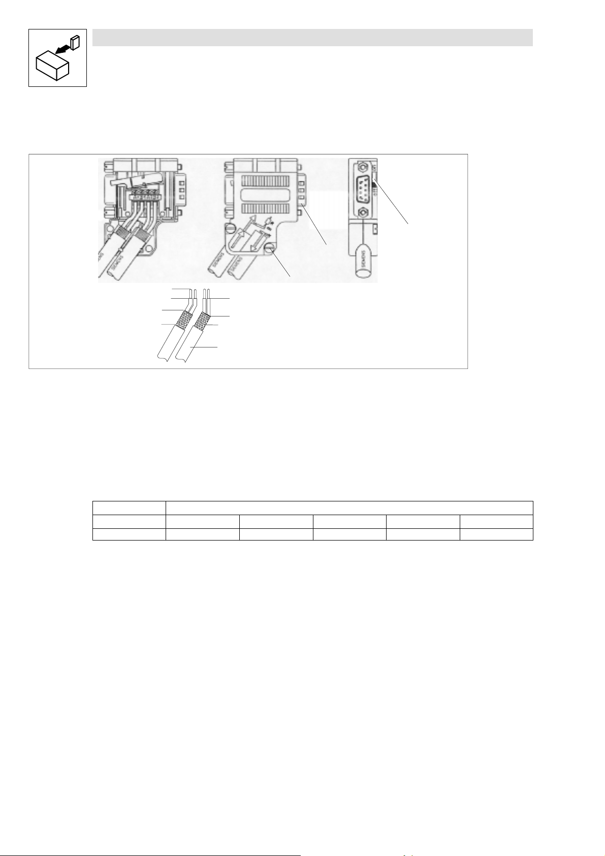
Connection of the bus cable in the bus connector (Siemens)
1
3
Enter approx. 5 mm
Enter approx. 11 mm
Fig. 4-4 Connection of the bus cable in the bus connector
19-poleSubDplug
2 Housing screw
3 Terminator
4 Cable screen (bare fit
5Buscable
(here
not connected)
inmetalguide required)
Enter approx. 16 mm
4
5
Length of the bus cable
The length of the bus cable depends on the baud rate:
9.6 - 93.75 187.5 500 1500 12000
Length [m] 1200 1000 400 200 100
2
Baud rate [k bit/s]
4-6
BA2131EN
Page 19

Installation
Show/Hide Bookmarks
BA2131EN
4-7
Page 20

Commissioning
Show/Hide Bookmarks
5 Commissioning
Stop!
l
Beforeswitching on the mains voltage check the wiring for completeness, short circuit and
earth fault.
l
Keep t o t he switch-on sequence!
(Chapter 5.1 to chapter 5.2.2)
5.1 Configuration of the host system for communication with the
2131 fieldbus module.
TheLenzecontrollers arePROFIBUS-DPparticipantsin conformitywithstandards.Communication
with the Simatic-S5 is possible, provided that the following Siemens hardware and software
components are available:
l
S5-interface module IM308-B or IM308-C
l
Programming software COM-ET 200
The COM-ET200 software is available in a DOS version (COM-E T200 DOS) and in a Windows
version (COM-ET200 WIN). The following two sections explain the specific controller settings for
both versions. The third section gives a program example which is to support the commissioning.
5.1.1 Settings with COM-ET200 DOS
Inthe following, wedescribe howto configurea Lenzecontroller forthe program packageCOM-ET
200 DOS:
1. Copy the file LE00AATD.200 from the diskette to the COM-ET200 directory .
2. Fill in the boxes of the menus indicated then:
Menu: ET200 system parameter
Bus profile: DP standard
Menu: Configure
Station type: Lenze 2131 Vxx
Configuration: User data with DP parameter-setting channel
0. = 115; 1. = 113 oder
0. = 115; 1. = 114
User data without DP parameter-setting channel
0. = 113 or
0. = 114
5.1.2 Settings with COM-ET200 WIN
In the following we describe how to configure a Lenze controller for the program package
COM-ET200 WIN:
1. Copy the file LE00AAAX.200 from the diskette to the COM-ET200 directory.
2. Select the 2131 fieldbus module via the slave family DRIVE S.
BA2131EN
5-1
Page 21

Commissioning
Show/Hide Bookmarks
3. Fill in the boxes of the following menu as indicated:
Menu: Configure
Station type: Lenze 2131 Vxx
Configuration: User data with DP parameter-setting channel
User data without DP parameter-setting channel
5.1.3 Program example
You will find a program example (file: 2130IBST.S5D) in STEP 5 on the attached diskette which
supports your commissioning. The program example comprisesthe followingfunction modules:
l
FB182: Process-data communication:
This is a simplified
drive control where the
standard functions of the Lenze drivecontrollers are mapped to the DRIVECO M-ProfilDRIV ECOM profile.
l
FB183: Parameter-data communication:
Thus function module supports the
DP parameter-setting channel. All
DRIV ECOM and Lenze parameters
can be written and read.
0. = 115; 1. = 113 oder
0. = 115; 1. = 114
0. = 113 or
0. = 114
5.2 Commissioni ng of the 2131 fieldbus module
1. Switch on the controller and, if necessary, the external supply of the 2131 fieldbus module.
The green bus LED for the supply voltage (see page 4-1; Fig. 4-1pos. 1) must be on.
The LED which displays the operating state of the controller must be on.
If the LEDs are not on, see chapter 7 “Troubleshooting and fault elimination“.
2. Set the station address (C0009)for each controller via the keypad or the host (seechapter
6.1.4, page 6-3).
If several controllers are interconnected in a network, it must be possible that the host
addresses each controller uniquely. Every controller therefore needs an address.
3. You can now communicate with the drive.
4. The control terminal 28 (ctrl. enable = controller enable)is always active and must be set to
HIGH level during operation (see Operating Instruction of the corresponding controller).
Otherwise, the controller cannot be enabled.
5.2.1 Drive control via PROFIBUS
82XX
1. For drive control with PROF I BUS, change the Lenze parameter operating mode (L-C0001)
from 0 to 3. (S eechapter 6.6.1). This change can be carried out using the 8201BB keypad or
thePROFIBUS.
Examples for PROFIBUS Write (L-C0001=3)
– Index = 5FFE
(results from 5FFF
hex
(L-C0001)
hex
; see Lenze code addressing (
hex
6-1)
5-2
BA2131EN
Page 22

Commissioning
Show/Hide Bookmarks
–Subindex:0
– V alue: 30000
2. Terminal 28 (controller enable)is always active and must be set to HIGH level during
PROFIBUSoperation (see the corresponding Operating Instructions).
– Otherwise the controller cannot be enabled by the PROFIBUS (DRIVECOM controller status
“OPERATION ENABLED“) .
– With 821X, 8200 vector and 822X the QSP function (quick stop)is always active. If QSP is
assigned to an input terminal (factory setting: not assigned), this terminal must be at HIGH
level during PROF I BUS operation (see the corresponding Operating Instructions).
The controller now accept s c ontrol and parameterdata from the PROFIBUS.
93XX
1. For drive control via PROFIBUS set the Lenze parameter Signal Configuration (L-C0005) to a
value xxx3. This change can be carried out via the 9371BB keypad or directly via PROFIBUS.
Note!
Werecommend the signal configuration C0005 = 1013 (speed control) for first commissioning.
(results from 3x10⁴; see chapter 6.1.1)
dec
Examples for PROFIBUS Write (L-C0005=1013):
– Index = 5FFA
(results from 5FFF
hex
(L-C0005)
hex
; see Lenze code addressing (
hex
6-1)
–Subindex:0
– V alue: 10 130 000
(results from 1013x104; see chapter 6.1.1)
dec
2. Set the parameter L-C0142 to 0.
3. Terminal 28 (ctrl. enable = controller enable)is always active and must be set to HIGH level
during PROFIBUSoperation (see the Operating Instructions of the controller). Otherwise the
controller cannot be enabled by the PROFIBUS (DRIVECOM controller status “OPER ATION
ENABLED“).
– With the signal configuration L-C0005=1013, the QSP function (quick stop) and the
CW/CCW changeover are assigned to the digital input terminals E1 and E2, and thus they
are always active. During PROFIBUS operation, E1 must be on HIGH level (see Operating
Instructions 93XX).
Note!
With thesignal configuration L-C0005=xx13, terminal A1 is switched as voltage output.Therefore,
only the following terminals must be connected via cable:
l
X5.A1 with X5.28 (ctrl. enable)
l
X5.A1withX5.E1(CW/QSP)
The controller now accept s c ontrol and parameterdata from the PROFIBUS.
5.2.2 Enable controller
BA2131EN
As standard, the controller is enabled as follows:
1. Select a speed setpoint with a value unequal 0 (see chapter 6.4.1 “Process-data assignment“
(6-10) .
2. Change to the status “READYFORSWIT CHON“.
Value = 0000 0000 0111 1110
bin
(007E
). in the DRIVE CO M control word.
hex
5-3
Page 23

Commissioning
Show/Hide Bookmarks
3. Wait for the status “READY FOR SWITCH ON“.
Value for DRIVECOM status word = xxxx xxxx x01x 0001
4. Change to the status “OPER ATION ENABLED“.
Value = 0000 0000 0111 1111
5. Wait for “OPERATION ENABLED“.
See also chapter 6.5.2 “DRIVECOM unit control“, page 6-14ff.
5.3 Diagnostics
If the initialization to the controller is not completed when using an external supply voltage for the
module (e.g. controller not switched on), the bit “static diagnostics” willbe set (station status byte
2, bit 1).
Thismeansthatthemodule cannotprovidevaliduserdata.Themastermustthenstop theuserdata
transfer and request diagnostics data until the bit “static diagnostics“ will not be set any longer.
bin
(007F
bin.
)in the DRIVECOM control word.
hex
5.4 Special featur es with 82XX, 8200 vector and 93XX
Please note
l
For safe operation it is absolutely necessary to observe the notes for the controllers given in this chapter.
l
Please observe the corresponding Operating Instructions of the controllers.
820X
821X, 822X
8200 vector
93XX
l
Parameter setting (codes except process data) is only possible when the controller is inhibited (DR IV ECO Mcontroller status unequal
“OPERA TIO NENABLED“). Parameters are accepted when the controller is enabled, but they are not saved.
l
A TRIPmust only be reset through PR OFIBUS:
If the contro ller isset tothe statusTRI Pwhile being operated with PROFIBUS con trol (L-C0001 = 3) and if the TRI Pis reset through terminal
28, the drive can start for a short time. When resetting a fault via PROFIBUS, this does not occur.
l
After the command “TR IP reset“ the 820Xcontroller is basically initialized. Duringthis time the controller doesnot accept any services.
l
Always send the direction of rotation with a low setpoint before the new setpoint:
If the setpoint and the direction of rotation are changed at the same time via the DRIVECO Mspeed setpoint, the speed can change to the
wrong direction or rotation for a short time. This is because first the setpoint is sent as unipolar value to the controller and then the
information about the direction of rotation is sent.
l
For first switch on, the automatic DC-injection brake must be activated in both parameter sets:
– C0106 = 0
– C2106 = 0
l
If the automatic DC-injection brake (DCB) is activated (DCB holding time LC106 <> 0) , the drive will automatically change from the status
“OPERA TIO NENABLED“ to the status “SWI TCHEDON“ when reaching the speed 0 and after the DCB holding time. If the setpoint is > 0, the
drive automatically changes to the status “OPER ATION ENABLED“.
l
Digital and analog input and output signals can be freely configured (see Operating Instructions for 8200 vector; codesC0410, C0412, C0417
and C0421)
l
The change of the code L-C0001 to xxx3 starts the preconfiguration of the process data words in the controller
l
Set the signal configu r ationL-C0005 = xxx3 instead of the operating mode L-C0001.
l
The change of the code L-C0005 to xxx3 starts the preconfiguration of the process data words in the controller
l
Set the parameter L-C0142 = 0 (autostart lock), to avoid a short time start of the drive during the initialization phase.
5-4
BA2131EN
Page 24

6 Parameter setting
Show/Hide Bookmarks
The parameter setting of the 2131 module is subdivided into:
l
Controller parameters, which can also be set with the 8201BB or 9371BB keypad.
l
2131 parameters, which can only be accessed via the 2131 fieldbus module.
Only the controller parameters are permanently saved in the corresponding controller.
Inthe following, you will onlyfind parameterswhichareimportant for theserial communication.For
further information on parameter setting of the controllers see the Manual 93XX or the Operating
Inst ructions of t he corresponding controller.
The PROFIBUS-DP transmits two different types of data between the host and the controllers.
l
Parameter, e.g. op eration parameters, diagnostic information, m ot or data.
In general, the transmission of parameters is not as time-critical as the transmission of the
second group of process data, but there is a larger data volume.
l
Process data, e.g. setpoints and actual value, which must be exchanged within a minimum
of t ime.
The data volume is small (e.g. 2 words with DRIVECOM or Lenze), which are to transmitted
cyclically.
For these two different tasks the transmitted data is divided into two logical communication
channels:
l
Parameter channel for the transfer of parameters
l
Process-data channel for fast transfer of process data. Process data are cyclically
transferred. Thus, the latest input and output data are constantly exchanged between the
host and the controllers.
Parameter setting
6.1 Parameters
Thesystem distinguishestwo parameter types: the Lenzeparameters which are implemented into
the Lenzecontrollers, and theDRIVECO Mparameters. Thischapter givesa shortdescriptionofthe
two parameter types and their relation to each other.
6.1.1 Lenze parameters
In general, the Lenze parameters of the Lenze controllers are addressed via the Lenze codes. For
detailed information about the Lenze parameters and their value ranges, see the Operating
Inst ructions of t he corresponding controllers.
Lenze codes
Inthese OperatingInstructions Lenzecodes are identified withL-Cxxxx, to ensurethat theyarenot
mixed up with the DRIVECOM index (e. g. L-C0001 for the Lenze code C0001).
Lenze code addressing
The access to Lenze parameters is possible. However, the addressing of the parameters (code
numbers)is shifted and calculated as follows:
Index = 24575 - LENZE_CODENR
Index
The index for Lenze code numbers is between 20576 (5060hex)and 24575 (5FFFhex).
Example:
The Lenze parameter L-C0001 (operating mode) can be accessed via the PROFIBUS-DP under
index 24574 ( = 24575 - 1).
hex
= 5FFF
- LENZE_CODENR
hex
hex
BA2131EN
6-1
Page 25

Parameter setting
Show/Hide Bookmarks
Lenze data types
The possible Lenze parameters and their value ranges can be obtained from the corresponding
Operating Instructions for the controller.
The data of the Lenze parameters are mainly represented in a fixed-point format of the data type
Integer32 with four decimal digits. This means, that the parameter value listed in the Operating
Instructions must be multiplied with 1000.
Example:
Operating Instructions L-C0039 (JOG)= 150.4 Hz
results in 150.4 x 10000 = 1504000
82Xxparameter sets
The 82XX controller is equipped with 2 parameter sets, which can be directly addressed via the
PROFIBUS. They are addressed by means of a code-digit offset:
l
Offset 0 addresses parameter set 1 with the Lenze codes L-C0000 to L-C1999
l
Offset 2000 addresses parameter set 2 with the Lenze codes L-C2000 to L-C3999
If a parameter is only available once (see 82XX Operating Instructions), use the code offset 0.
Example for L-C0011 (maximum field frequency):
L-C0011 in parameter set 1: Lenze code = 11
L-C0011 in parameter set 2: Lenze code = 2011
Changes of the parameters are automatically saved in the controller (see Operating Instructions
82XX). Exceptions are theprocess data,e.g. control words or setpoints.
(0016F300
dec
hex
)
Parameter sets for 8200 vector
The8200 vectorcontroller is equipped with4 parametersets, which can bedirectly addressed via
the PROFIBUS. They are addressed by means of a code-digit offset:
l
Offset 0 addresses parameter set 1 with the Lenze codes L-C0000 to L-C1999
l
Offset 2000 addresses parameter set 2 with the Lenze codes L-C2000 to L-C3999
l
Offset 4000 addresses parameter set 3 with the Lenze codes L-C3000 to L-C4999
l
Offset 6000 addresses parameter set 4 with the Lenze codes L-C6000 to L-C7999
If a parameter is only available once (see Operating Instructions 8200 vector), use the codeoffset
0.
Example for L-C0011 (maximum field frequency):
L-C0011 in parameter set 1: Lenze code = 11
L-C0011 in parameter set 2: Lenze code = 2011
L-C0011 in parameter set 3: Lenze code = 4011
L-C0011 in parameter set 4: Lenze code = 6011
Changes of the parameters are automatically saved in the controller (see Operating Instructions
8200 vector). Exceptions are the process data, e.g. control words or setpoints.
Parameter sets for 93XX
The 93XX controllers are equipped with 4 parameter sets for non-volatile storage. Another
parameter set is in the user memory of the controller. This is the current parameter set. Only the
current parameter set can be directly addressed via PROFIBUS. For the codes, see Operating
Instructions or Manual for 93XX . Changes of the current parameter set will be lost after switching
off the controller. Code C0003 is for saving the current parameter set. After switching on the
controller , parameter set 1 is automatically loaded into the current parameter set.
6.1.2 DRIVECOM pa ra meters
In the following, the controller parameters, which are standardized according to the DRIVECOM
profile20,arenamedDRIV ECOM parameters.Each DRIVECOM parameteris addressed by means
of the index.
6-2
BA2131EN
Page 26

Parameter setting
Show/Hide Bookmarks
6.1.3 Operating mode C0001
82XX / 8200 vector controllers
CodeC0001 (Operatingmode)determines thesource( terminal, keypad, PROFIBUS)which writes
the frequency setpoint (C0046)and the control word (C0135).
C0001 = 0 1 2 3
Read andwriteparameter yes yes yes yes
P arameter C0046 no yes no yes
Process data no no no yes
Independently of the selected operating mode (C0001), the controller can be inhibited under the
code C0040 via the PROFIBUS.
Please note that the operating mode C0001is available in both parameter sets.Thus, C0001 must
be set identically in both parameter sets.
PROFIBUScontrol (C0001= 3)is subject to theoperatingmodeinparameterset1. Terminalcontrol
(C0001 <> 3) is subject to the operating mode in parameter set 1.
93XX controllers
The93X Xcontroller does not provide an operating mode which can bechanged by only one code.
The93XXcontroller i operated via the“control codes“. By means ofthe control codesit is possible
to select the signal source valid for an input. Thesignal sourcecan be a terminal, an internalsignal
or a signal of a bus system.
For further information refer to the 93XX Manual.
6.1.4 Bus address/station address
To address the controllers in the PROFIBUS system, each participant gets an address. Each
participant must have a different address. This address is called station address.
The address can be set in two different ways:
l
Address setting via the keypad or PC program:
– Set the address under code C0009 in the controller.
– The valid address range is the unit address 3 ¤ 99.
l
Setting of the unit address through a master (only master class 2):
– With this method only one PROFIBUS participant must be connected. This can be achieved
by a special switch-on sequence.
– The Lenze setting of C0009 is 1. This means that the station address is addressed with 126.
If C0009 is set to 2, the station addresses 100 ¤ 125 can be selected.
BA2131EN
6-3
Page 27

Parameter setting
Show/Hide Bookmarks
Thefollowingtableshowstheassignmentoftheaddresses:
PROFIBUS-DP station address Mapping to code C0009 LECOM unit address
1-2 No (master addresses)
3-99 Yes (3-99)
100-125 Yes (C0009=2)
126 (Lenze setting ) Yes (C0009=1 )
6.1.5 Baud rate
Baud-ratesettingsarenot required.The2131 fieldbusmoduleisautomatically adjusted tothebaud
rate of the master.
6.1.6 Master settings
Themasterneedsaunit-descriptionfile(unitmaster-data file)foroperationwithPROFIBUS-DP.The
diskette provides the following files:
File name Meaning
L_AR00AA.GSD Unit master-data file to DIN 19245 T3
LE00A ATD.200 Contro ller master data file (type file) for Simatic-S5 COM-ET200 V4.X (IM308B )
LE00AAAX.200 Controller master data file (type data) forSimatic-S5 COM-ET 200V5.X(IM308C)
You also have to set:
Function Setting (depends on the master t ype)
Baud rate The 2131 module is equipped with an automatic baud-rate detection
Communication profile PROFIBUS-DPDINE 19245 T3
Slave-station address 126(Lenze setting)
DP-configuration data (configuration) see chapter 6.2
PNO-identification number 00AA
DPuser-datalength see chapter 6.2
Value the same as in controller parameterC0009 (see chapter 6.1.4 “Bus
address/station address“).
6.2 PROFIBUS-DP configuration
ThePROFIBUS-DPuser datalength is determined duringtheDPinitializationphase(configuration).
You can select from 4 fixed lengths.
The user data lengths for input data and output data must be the same.
For simplification we use the following abbreviations:
l
PIW:
Process input word (process data from the controller to the master)
l
POW:
Process output word (process data from the master to the controller)
hex
The 4 selectable user data lengths are:
l
2 words process data; label 71
PIW/POW 1 PIW/POW 2
Byte 1 Byte 2 Byte 3 Byte 4
6-4
(113)
hex
BA2131EN
Page 28

Parameter setting
Show/Hide Bookmarks
l
3 words process data; label 72
PIW/POW 1 PIW/POW 2 PIW/POW 3
Byte 1 Byte 2 Byte 3 Byte 4 Byte 5 Byte 6
l
DP parameter-setting channel1)+ 2 words process data;
label 73
DP parameter-setting channel PIW/POW 1 PIW/POW 2
Byte 1 Byte 8 Byte 9 Byte 10 Byte 11 Byte12
1) see chapter 6.3
l
DP parameter-setting channel1)+ 3 words process data;
label 73
DP parameter-setting channel PIW/POW 1 PIW/POW 2 PIW/POW 3
Byte 1 Byte 8 Byte 9 Byte 10 Byte 11 Byte 12 Byte 13 Byte 14
1) see chapter 6.3
hex71hex
hex72hex
(115, 113)
(115, 114)
hex
(114)
6.3 PROFIBUS-DP parameter-setting channel
ThePROF I BUSDPparameter-settingchanneloffersaparameter settinganddiagnosticspossibility
for controllers. It is therefore possible to access all Lenze parameters (codes).
If theDPparameter-setting channelisactive, it assignsthe first 8 bytes of theand input and output
data. The DP parameter-setting channel has the same structure for both transmission directions.
6.3.1 Structure of the DP parameter-setting channel
Byte 1 Byte 2 Byte 3 Byte 4 Byte 5 Byte 6 Byte 7 Byte 8
Service Subindex Index
High byte
Byte 1: Service
Job and response control for the DP parameter-channel.
Bit no. Meaning
0-2 Service
Job for the controller. The bits are set only by the master.
l
0=nojob
l
1 = read job (read data from the controller)
l
2 = write job ( write data to the controller )
3 Reserved
4-5 Data length
Length of the data in the field data/error.
l
0=1byte
l
1=2byte
l
2=3byte
l
3=4byte
6 Handshake
Indicates a new job. The master changes this bit for every new job. The controller copies the bit to its response message.
7 Status
Status information from the controller to the master when sending acknowledgement. This bit informs the master whether the job
was carried out without faults.
l
0 = Job completed with fault.
l
1 = Job not completed. A fault occured. The data in the field Data/Error are interpreted as error message.
Index
Low byte
Data 4
(Erro r4)
Data 3
(Erro r3)
Data 2
(Error 2)
Data 1
(Error 1)
BA2131EN
6-5
Page 29

Parameter setting
g
Show/Hide Bookmarks
Byte 2: Subindex
l
The series 82XX do not have codes with subindex, the value is always 0.
l
With the series 93XX it is necessary for many codes to address them additionally via a
subindex.
Example: Code C0039 subindex 3 adresses JOG 3
Byte 3 and 4: Index
The parameters or the Lenze codes are selected with these two bytes according to the formula:
Index = 24575 - Lenze code number
Example:
The parameter C0012 (acceleration time) is to be addressed:
24575 - 12 = 24563 = 5FF3
The entries for this example would be:
l
Byte3:IndexHighByte=5F
l
Byte 4: IndexLow Byte = F3
hex
hex
hex
Byte5-8:data1-4;error1-4
Parameter value or fault information indicated with invalid access. The status ofthe bit Job/Status
determines the meaning of the data field.
Data
Parameter value, which assigns 1 to 4 bytes depending on the data format. Strings or data blocks
cannot be transferred.
The most common data format in Lenze controllers is a fixed-point format with 4 decimal places.
Pleasenote, that theseparametersmust bemultiplied by10,000,e.g. thevalue10willbedisplayed
as value 100,000.
Thedataisfiled accordingto theMotorolaformat, i.e. first highbyte/high word, secondlow byte/low
word.
Byte 5 High byte 1
Byte 6 Low byte 1
Byte 7 High byte 2
Byte 8 Low byte 2
High word D ouble word
Low word
Error
Fault detection (for description see the following table).
l
Byte 5: Error c lass
l
Byte 6: Error c ode
l
Byte 7: Additional code (high byte)
l
Byte8: Additionalcode(low byte)
6-6
BA2131EN
Page 30

Fault messages in the error field (Data/Error)
Show/Hide Bookmarks
Parameter setting
Error class Error
code
0 0 00 No fault
6 3 00 No access permission
6 5 10 Inadmissible job parameter
6 5 11 Invalid subindex
6 5 12 D ata toolong
6 7 00 The object does not exist
6 8 00 D ata types are notidentical
8 0 21 Cannot be executed because of local control
8 0 22 Cannot be executed because of unit status
8 0 30 Leave value range
8 0 40 Collision with other values
8 0 20 Service cannot be executed currently
Additional
code [hex]
Meaning
6.3.2 Parameter communication w ith the controller
Read job
1. Determine the user dataof thecontroller: i. e. determinethelocationof theDPuserdatain
thehost.
2. Enter the address of the desired parameter in the field ”Index and subindex“ (DPoutput
data).
3. Job/service = Read job and the bit “job/handshake“ must be changed (DP output data).
4. Check, whether the bit “job/handshake“ is the same for the DP input data and the DP output
data. If the bit “job/handshake“ is the same, the response has been received. You should
implement a time monitoring.
5. Check, whether the bit “job/status“ is set. If the bit “job/status“ is not set, the field
“data/error“ contains the required parameter value. If the bit “job/status“ is set, the reading
job is not executed properly and the field “data/error“ contains an error information.
Write job
1. Determine the user-data range of the controller, i. e. determine the location of the DP
user-data in the host system.
2. Enter the address of the desired parameter in the field “Index and subindex“ (DPoutput
data).
3. Entertheparameter valueinto thefield Data/Error.
4. Job/Service = Write job and the bit job/handshake must be changed (DP output data).
5. Check, whether the bit “job/handshake“ is the same for the DP input data and the DP output
data. If the bit “job/handshake“ is the same, the response has been received. You should
implement a time monitoring.
6. Check, whether the bit “job/status“ is set. If the bit “job/status“ is not set, the job has not
been executed properly and the field “data/error“ contains an error information. Otherwise,
the job has been executed without any faults.
BA2131EN
6-7
Page 31

Parameter setting
Show/Hide Bookmarks
6.3.3 Example 1: Write parameter
Task
The acceleration time C0012 of the controller is to be changed to 20 s.
Job (byte 1/service)
Bit 0-2 = 2 Write job (xxxx x010)
Bit 3 = 0 Reserved (xxxx 0010)
Bit 4-5 = 3 Data length 4 byte (xx11 0010)
Bit 6 = X Handshake changes frequently (xX 110010)
Bit 7 = 0 Only relevant with response (0x110010)
SUBINDEX (byte 2)
Subindex = 0, as there is not subindex under code C0012.
INDEX (byte 3 + 4)
Index calculation:
Index = 24575 - code number
Index = 24575 - 12 = 24563 = 5FF3hex
DATA(byte5-8)
Calculation of the value for the acceleration time
20 s x 10.000 = 200.000 = 00 03 0D 40hex
Response to drive
Byte 1 Byte 2 Byte 3 Byte 4 Byte 5 Byte 6 Byte 7 Byte 8
Service Subindex Index
High byte
0x11 0010 0 5F F3 00 03 0D 40
Index
Low byte
Data 4 Data 3 Data 2 Data 1
Response of the c ontroller w hen no fault occurs
Byte 1 Byte 2 Byte 3 Byte 4 Byte 5 Byte 6 Byte 7 Byte 8
Service Subindex Index
High byte
0x11 0000 0 5F F3 00 00 00 00
Index
Low byte
Data 4 Data 3 Data 2 Data 1
6-8
BA2131EN
Page 32

6.3.4 Example 2: Write parameter
Show/Hide Bookmarks
Task
The heatsink temperature (value = 43 C) C0061 is to be read by the controller.
Job (byte 1/service)
Bit 0-2 = 2 Write job (xxxx x001)
Bit 3 = 0 Reserved (xxxx 0001)
Bit 4-5 = 3 Data length 4 byte (xx11 0001)
Bit 6 = X Handshake changes frequently (xx110001)
Bit 7 = 0 Only relevant with response (0x110001)
SUBINDEX (byte 2)
Subindex = 0, as there is not subindex under code C0061.
INDEX (byte 3 + 4)
Parameter setting
Index calculation:
Index = 24575 - code number
Index = 24575 - 61 = 24514 = 5FC2
Response to drive
Byte 1 Byte 2 Byte 3 Byte 4 Byte 5 Byte 6 Byte 7 Byte 8
Service Subindex Index
0x11 0001 0 5F C2 00 00 00 00
Response of the c ontroller w hen no fault occurs
Byte 1 Byte 2 Byte 3 Byte 4 Byte 5 Byte 6 Byte 7 Byte 8
Service Subindex Index
0x11 0000 0 5F C2 00 06 8F B0
Index of the read request = 5FC2
Data1todata4=43C x 10000 = 430000 = 00 06 8F B0
6.4 Process data
High byte
High byte
hex
hex
Index
Low byte
Index
Low byte
Data 4 Data 3 Data 2 Data 1
Data 4 Data 3 Data 2 Data 1
BA2131EN
Process data are data memories in which several parameters for a new parameter - the process
data - are summarized for fast transmission.Thehost has direct access to theprocessdata. In the
PLC, for instance, the data are directly assigned to the I/O area. These process data are cyclically
exchanged between the controller and the master. They are subdivided into
l
Process output data (PO data)
l
Process input data (P Idata)
Herethedataflowstartsfrom themaster,i.e.the POdataofthe masterarePIdataforthecontroller.
The controller getsthecontrolinformation fromthemaster andreturnsstatus information.
6-9
Page 33

Parameter setting
Show/Hide Bookmarks
6.4.1 Process-data assignments for 82XX
Structure of the PO- data response (data to drive)
Byte 1 Byte 2 Byte 3 Byte 4
DRI V ECOMcontrol word
High byte
DRIV ECOM control word: see chapter 6.5.3 or chapter 6.5.2.
Setpoint: frequency setpoint
Here thefrequency setpoint is preselected as process data word. The standardization differs from
C0046. It is indicated with a sign:
Structure of the PI data response (data from drive)
Byte 1 Byte 2 Byte 3 Byte 4
DRIVECOM status word
High byte
DRI V ECOMcontrol word
Low byte
á
24000 =á480 Hz.
DRIVECOM status word
Low byte
Setpoint
High byte
Actual value
High byte
Setpoint
Low byte
Actual value
Low byte
DRIV ECOM status word: see chapter 6.5.4 or chapter 6.5.2.
Actual value: act. frequency value
The actual frequency value is indicated with a sign:
6.4.2 Process-data assignment for 8200 vector
Structure of the PO data response
Digital and analog input and output signals can be freely configured (see Operating Instructions for
8200 vector; codes C0410, C0412, C0417 and C0421)
Byte 1 Byte 2 Byte 3 Byte 4 Byte 5 Byte 6
DRIVECOM
Control word
High byte
Structure of the PI- data response
Byte 1 Byte 2 Byte 3 Byte 4 Byte 5 Byte 6
DRIVECOM
Status word
High byte
DRIVECOM
Control word
Low byte
DRIVECOM
Status word
Low byte
AIF-IN .W1
High byte
AIF-OU T.W 1
High byte
AIF-IN .W1
Low byte
AIF-OU T.W 1
Low byte
á
24000 =á480 Hz.
AIF-IN .W2
High byte
AIF-OU T.W 2
High byte
AIF-IN .W2
Low byte
AIF-OU T.W 2
Low byte
6-10
BA2131EN
Page 34

6.4.3 Process-data assignment for 93XX
Show/Hide Bookmarks
Unlike the82XXcontroller,the process-data assignment ofthe 93XXcontroller canbe changed via
reconfiguration of the function blocks AIF-IN and AIF-OUT.
Structure of the PO data response
Byte 1 Byte 2 Byte 3 Byte 4 Byte 5 Byte 6
DRIVECOM
Control word
High byte
AIF-IN.W1 to AIF-IN.W2 depend on the signal configuration selected under L-C0005 and are then
sensibly preassigned.
Signal configuration (L-C0005) AIF-IN.W1 AIF-IN.W2
Speed control
1003
1013
1113
Torque control
4003
4013
4113
DF master
5003
5013
5113
DF-slave bus
6003
6013
6113
DF-slave cascade
7003
7013
7113
Not equal to xxx3 (except own
configurations)
DRIVECOM
Control word
Low byte
AIF-IN .W1
High byte
NSET-N
Speed setpoint
MCTRL-MADD
Torque setpoint
NSET-N
Speed setpoint
DFSET-A-TRIM
Phase trimming
DFSET-V P-DIV
DF factor
Not assigned Not assigned
Parameter setting
AIF-IN .W1
Low byte
AIF-IN .W2
High byte
Not assigned
Not assigned
Not assigned
DFSET-N-TRIM
Speed trimming
DFSET-A-TRIM
Phase trimming
AIF-IN .W2
Low byte
For detailed description of the 93XX signal configuration see the Operating Instructions for 93XX
(only the main configurations: 1000, 4000, 5000, etc.) or the Manual 93XX.
In the controller other signals can be assigned to AIF-IN.W1 to AIF-IN.W2. For this, the
function-block configuration - described in the Manual 93XX - is used. The function block AIF-IN
determines the input data of the controller as data interface for the 2131IB fieldbus module.
For more detailed information about the function block AIF-IN, see the Manual 93XX.
BA2131EN
6-11
Page 35

Parameter setting
X
Show/Hide Bookmarks
A IF -IN *
)
AIF-C TRL.B3
16 Bit
C 0136/3
16 Bit
16 Bit
16 Bit
C 0855/1
16 binary
signals
C 0855/2
16 binary
signals
16 Bit
Low W ord
16 Bit
H igh W ord
AIF-C TRL.B8
AIF-C TRL.B9
AIF-C TRL.B10
AIF-C TRL.B11
C 0856/1
16 Bit
Low W ord
16 Bit
C 1197
H igh W ord
C 0856/2
C 0856/3
C 0857
AIF-IN
AIF-C TRL.B3
AIF-C TRL.B8
AIF-C TRL.B9
AIF-C TRL.B10
AIF-C TRL.B11
Bit 0
16 Bit
C ontrol w ord
Bit 15
B y te 3 ,4
1
B y te 5 ,6
B y te 7 ,8
16 Bit
16 Bit
16 Bit
C 0855/1
16 binary
signals
C 0855/2
16 binary
signals
16 Bit
Low W ord
16 B it
High W ord
C 0856/1
C 0856/2
C 0856/3
C 0857
DCTRL
QSP
DISABLE
CINH
TRIP -SE T
TRIP -R ESET
AIF-CTRL.B0
AIF-CTRL.B1
AIF-CTRL.B2
AIF-CTRL.B4
AIF-CTRL.B5
AIF-CTRL.B6
AIF-CTRL.B7
AIF-CTRL.B12
AIF-CTRL.B13
AIF-CTRL.B14
AIF-CTRL.B15
A IF - IN .W 1
A IF - IN .W 2
AIF-IN.W 3
AIF-IN.B0
AIF-IN.B2
. . .. . .
A IF - IN .B 1 4
A IF - IN .B 1 5
AIF-IN.B16
AIF-IN.B17
A IF - IN .B 3 0
A IF - IN .B 3 1
A IF - IN .D 1
Bit 0
S teuerw ort
Bit 15
B y te 3 ,4B y te 5 ,6
X1
B y te 7 ,8
DCTRL
QSP
DISABLE
CINH
TRIP -S ET
TRIP -R ESE T
AIF-C TRL.B0
AIF-C TRL.B1
AIF-C TRL.B2
AIF-C TRL.B4
AIF-C TRL.B5
AIF-C TRL.B6
AIF-C TRL.B7
AIF-CTRL.B12
AIF-CTRL.B13
AIF-CTRL.B14
AIF-CTRL.B15
A IF - IN .W 1
A IF - IN .D 2
A IF - IN .W 2
A IF - IN .W 3
AIF-IN.B0
AIF-IN.B2
. . .. . .
A IF - IN .B 1 4
A IF - IN .B 1 5
AIF-IN.B16
AIF-IN.B17
A IF - IN .B 3 0
A IF - IN .B 3 1
AIF-IN.D1
2111IBU003
Fig. 6-1 Function block AIF-IN and AIF-IN
(AIF-IN*)is available for the 9300 technology variants servo inverter, positioning controller and cam profiler as of software
version2.0)
DRIVECOM control word:
The assignment of t he DRIVECOM control word differsfrom the AIFcontrol word
For further information see chapter 6.5.2 or chapter 6.5.3.
Structure of the PI- data response
Byte 1 Byte 2 Byte 3 Byte 4 Byte 5 Byte 6
DRIVECOM
Status word
High byte
For more detailed information about the function block AIF-OUT, see the Manual 93XX.
6-12
DRIVECOM
Status word
Low byte
*)
AIF-OU T.W 1
High byte
BA2131EN
AIF-OU T.W 1
Low byte
AIF-OU T.W 2
High byte
AIF-OU T.W 2
Low byte
Page 36

C 0156/1
Show/Hide Bookmarks
C 0156/6
C 0156/7
C 0850/1
C 0850/2
C 0850/3
C 0116/1
C 0116/16
C 0116/17
C 0116/32
C 0851
STAT
STAT.B0
DCTRL-IMP
...
STAT.B14
STAT.B15
C 0858/1
C 0858/2
C 0858/3
FDO -0
...
FDO -15
FDO -16
...
FDO -31
AIF-O UT.D 1
C 0859
FDO
16 Bit
AIF-O UT.W 1
AIF-O UT.W 2
AIF-O UT.W 3
16 Bit
Low W ord
16 Bit
H igh W ord
16 Bit
Low W ord
16 Bit
H igh W ord
C 0852
0
1
2
C 0853
0
1
2
AIF-O UT
Bit 0
Bit 15
Bit 0
Bit 15
Bit 0
Bit 31
Parameter setting
)
AIF-O UT *
STAT
STAT.B0
C 0156/1
DCTRL-IMP
...
STAT.B14
C 0156/6
STAT.B15
Status w ord
B y te 3 ,4
X1
B y te 5 ,6
B y te 7 ,8
C 0156/7
C 1195
C 0850/1
C 0850/2
C 0850/3
C 0116/1
C 0116/16
C 0116/17
C 0116/32
C 0851
AIF-O UT.D 2
C 1196
AIF-O UT.W 1
C 0858/1
C 0858/2
C 0858/3
FDO -0
...
FDO -15
FDO -16
...
FDO -31
AIF-O UT.D 1
C 0859
FDO
16 Bit
16 Bit
Low W ord
16 Bit
H igh W ord
AIF-O UT.W 2
AIF-O UT.W 3
16 Bit
Low W ord
16 Bit
H igh W ord
16 Bit
Low W ord
16 Bit
H igh W ord
C 0854
0
3
C 0852
0
1
2
3
C 0853
0
1
2
Bit 0
Bit 15
Bit 0
Bit 15
Bit 0
Bit 31
Status w ord
B y te 3 ,4
X1
B y te 5 ,6
B y te 7 ,8
2111IBU002
Fig. 6-2 Function block AIF-OUT and AIF-OUT*)(AIF-OUT*)is available for the 9300 technology variants servo inverter, positioning
controller and cam profiler as of software version 2.0)
DRIVECOM status word:
The assignment of the DRIVECOM status word differs from the AIF status word!
For further information see chapter 6.5.2 or chapter 6.5.3.
6.5 Controller status
6.5.1 Standard unit control
For standard control you enter the control information via the corresponding control inputs
(terminal):
With82XXcontrollers,the corresponding control inputisselectedviathe LenzeparameterL-C0001
(operating mode).
Information about the current unit status (Fig. 6-3, see below) (rectangles) are available in the
DRIVECOM parameter “status word“. Commandsin the DRIVECOM parameter“controlword“ are
switched off andcannotchangethecontrollerstatus.Thecommandsto changethecontrollerstatus
are entered via the corresponding control inputs. These commands are marked by arrows in the
following diagram.
BA2131EN
6-13
Page 37

Parameter setting
Show/Hide Bookmarks
Switch on unit
NOT READY TO SWITCH ON
Status word xxxx xxxx x0xx 0000
automatically when
initializing is completed
READY TO SWITCH ON
Status word xxxx xxxx x01x 0001
automatically
SWITCHED ON
Status word xxxx xxxx x01x 0011
Ctrl.enable** Ctrl.inhibit**
OPERATION ENABLED
Status word xxxx xxxx x01x 0111
QSP**
TRIP (fault)
Fault
Status word xxxx xxxx x0xx 1000
TRIP reset**
Note:
The terms marked with ** are
commands
Fig. 6-3 Status diagram for standard unit control
Status
NOT READY TO SWITCHONThe controller is being initialized and is not yet ready to operate.
READYTOSWITCHON The controller is inhibited and waits for the power stage to be charged. It then automatically switches to the status “SWITCHED ON“.
SWI TCHEDON The controller is inhibited and waits for controller enable.
OPER A TI ONENABLED The controller is enabled. In this status, a pulse inhibit can be set automatically.
FAUL T The controller is in the status “FAULT“ (TR IP ) .
Meaning
It then automaticallyswitchesto the statusREADYTOSWITCHON.
6.5.2 DRIVECOM unit control
With PROFIBUScontrol (for 82XX:Lenze parameter L-C0001=3; for 93XX:always)and whenusing
the 2131 fieldbus module, Lenze controllers have a controller status as standardized in the
DRIV ECOM profile 20.
Information about the current unit status (Fig. 6-4, see below) (rectangles) are available in the
DRIVECOM parameter “status word“. Commands in theDRIVECOM p arametercontrol word can
change the controller status. These commands are marked by arrows in the following diagram.
6-14
BA2131EN
Page 38

Parameter setting
Show/Hide Bookmarks
NOTREADY TO SWITCHON
Status word xxxx xxxxx0xx 0000
automatically when in-
itializing is completed
Status word xxxx xxxxx0xx 0000
9
Inhibit voltage
xxxx xxxx xxxxxx0x
READY TO SWITCH ON
Status word xxxx xxxxx01x 0001
8
Standstill
xxxx xxxx xxxx
x110
Status word xxxx xxxxx01x 0011
Example:
Status information by means of “status word“
Bit 15 ... bit 0 (binary display)
Switch on unit
SWITCH ONINHIBIT
10
2
Standstill
xxxx xxxx
xxxx x110
3
Switchon
xxxx xxxx
xxxx x111
SWITCHED ON
Inhibit voltage
xxxx xxxx xxxxxx0x
Quick stop
xxxx xxxx xxxxx01x
6
Standstill
xxxx xxxx xxxxx110
13
Fault
was
recognized
MALFUNCTION REACTIONACTIVE
Status word xxxx xxxxx0xx 1111
automatically when
fault reactionis over
Fault
Status word xxxx xxxxx0xx 1000
14
Reset fault
xxxx xxxx 0xxx xxxx
xxxx xxxx 1xxx xxxx
12
Inhibit voltage
xxxx xxxx xxxxxx01
or
quickstop completed
7
45
Operation enable
xxxx xxxx xxxx1111 and
act. speed value <> 0*
OPERATION ENABLED
Status word xxxx xxxxx01x 0111
Inhibit RFGismappedtoquick
stop
Operation inhibit
xxxx xxxx xxxx0111 or act.
speed value = 0*
QUICK STOP ACTIVE
Status word xxxx xxxxx01x 0111
11
Quick stop
xxxx xxxx xxxxx01x
*onlyeffectivefor821X,8200 vectorwhenthe
automatic DC-injection brakeisactive(L-C0106,
Note:
L-C2106 <> 0)
Fig. 6-4 Status diagram DRIVECOM unit control
Status
Meaning
NOT READY TO SWITCHONThe controller is being initialized and is not yet ready to operate. It automatically switches to the status READYTO SWITCH ON.
SWI TCH-ON INHIBIT The controller is inhibited and waits for command 2 (shut down) .
READYTOSWITCHON The controller is inhibited and waits for command 3 (switch on).
SWI TCHEDON The controller is inhibited and waits for command 4 (enable operation).
OPER A TI ONENABLED The controller is enabled. In this status, a pulse inhibit can be set automatically.
FAULT REACTIONACTIVE A fault (TRIP )was recognized and a fault response initiated.
FAUL T The controller is in the status “FAULT“ (TRIP).
QUICK STOP ACTIVE While being in the status “OPERATIONENABLED“ the command “quick stop“ was set. The controller is decelerated in a controlled way
(quick-stop ramp). After deceleration, the controller automatically changes to the controller status “SWITCH ON INHIBIT“.
BA2131EN
6-15
Page 39

Parameter setting
Show/Hide Bookmarks
Command Meaning
CO MMAND 2, 6, 8 (standstill)
Control word: bit 0 = 0
COMMAND 3 (switch on) Co mmandto change tothe controllerstatus“SWITCHEDON“.
COMM AND4 (enable operation) Command to change to the controller status “OP ER A TIO NENABLED“. The controller inhibit is deactivated.
COMM AND5 (inhibit operation) Command to change to the controller status “SWITCHED ON“. The controller inhibit is activated.
COMMAND 7, 9, 10, 12 (v oltage inhibit)
Control word: bit 1 = 0
COMMAND 7, 10, 11 (quick stop)
Control word: bit 2 = 0
COMM AN D13 (FAU LT/TR IP ) The controller has recognized a malfunction. For some malfunction a controlled deceleration may be necessary
COMMAND14 (reset fault/TRIP)
A
Control word: bit 7 = 0
1
The individual bit-control commands of the control word depend on other bit positions. In the
following you will find a description of the bits required to effect the command.
Commandto change from differen tstates to the status“READYTO SWITCHON“.
Command to change to the controller status “SWITCH ON INHIBIT“. The controller inhibit is activated.
Command to change to the controller status “SWITCH ON INHIBIT“. If the controller was enabled, it is decelerated in a
controlled way along the Lenze quick-stop ramp.
(depending on the controller). Once completed, the controller changes to the status FAUL T.
W iththe series 821X, 8200 vector this com mand ackno w ledg esa fault. The controller changes to the status “SW ITCHON
INHIBI T“ when a fault is no longer recognized.
Controller status commands Bits of the control word
Bit 7 6 5 4 3 2 1 0
1 Standstill 1 1 0
2Switchon 1 1 1
3 Operation enable 1 1 1 1
4 Operation inhibit 0 1 1 1
5 V oltage inhibit 0
6 Quick stop 0 1
8Faultreset 01
Fault reset
RFG-zero
RFG-stop
RFG inhibit
Operation enable
Quick stop
V oltage inhibit
Switch on
Explanation:
0 = Bit status is 0
1 = Bit status is 1
empty = Any bit status, no influence
6-16
BA2131EN
Page 40

Parameter setting
Show/Hide Bookmarks
Theactualunit status can only beclarified by combining the unit-status informationbits (bit 0 to 6).
This is shown in the following:
Unit status Bits of the status word
Bit 6 5 4 3 2 1 0
NOTREADYTOSWITCHON 0 0 0 0 0
SWI TCH-ON INHIBIT 1 0 0 0 0
READYTOSWITCHON 0 1 0 0 0 1
SWI TCHEDON 0 1 0 0 1 1
OPER A TI ONENABLED 0 1 0 1 1 1
FAUL T 0 1 0 0 0
FAULT REACTIONACTIVE 0 1 1 1 1
QUICK STOP ACTIVE 0 0 0 1 1 1
Switch-on inhibit
Quick stop
V oltage inhibit
Fault
Operation enabled
Switched on
Readytoswitchon
Explanation:
0 = Bit statusis0
1 = Bit statusis1
empty = Any bit status, no influence
6.5.3 Control word
Note!
Thesingle bit control commands of the control word depend on other bit positions. Chapter 6.5.2
describes the bits required to effect the command.
BA2131EN
6-17
Page 41

Parameter setting
Show/Hide Bookmarks
Structure of the parameter “control word“
Bit Name Meaning
0 Switch on Controller status
1 Inhibit voltage Controller status
2 Quick stop Con troller status
3 Operationenable Contr oller status
4 RFG inhibit Inhibit of the ramp-funtion generator . Quick stop is activated without the controller leaving its status.
5 FREE
DRIVECOM:
RFG-stop
6 FREE
DRIVECOM:
RFG-zero
7 Fault reset Fault reset (TR IP ) . For this, a bit change from 0 to 1 is required.
8 Reserve DRIV ECOM reserved
9 Reserve DRIV ECOM reserved
10 Reserve DRIVECOM reserved
11 FREE
DRIVECOM:
Manufacturer
12 FREE
DRIVECOM:
Manufacturer
13 FREE
DRIVECOM:
Manufacturer
14 FREE
DRIVECOM:
Manufacturer
15 FREE
DRIVECOM:
Manufacturer
1)
0 = command 2, 6, 8 (controller inhibit)
1 = command 3 (controller inhibit)
0 = command 9, 10, 12 (controller inhibit)
1 = command “voltage inhibit“ not active
0 = Command 7, 10, 11 (quick stop)
1 = Command “quick stop“ not active
0 = Command 5 (controller inhibit)
1 = Command 4 (controller inhibit not active)
0 = RfG inhibit (quick stop)
1 = RFG inhibit not active
820X: Not assig ned
821X, 822X: Output of the R FG(sp eedsetpoint integrator)is ”frozen”.
8200 vector,93XX: free. Mapp in gto bit AIF-CTRL.B4 negated
820X: Not assig ned
821X, 822X: Input of the ramp function generator (speed
8200 vector; 93XX : free. Mapp ing to bit AIF-CTRL .B 5negated
For 82XX, the controller is initialized. During this time, the controller does not accept any commands.
820X: No tassigned
93XX: free. Mapping to bit AIF-CTRL.B7
820X, 821X,822X: Parameter set changeover:
8200 vector,93XX: free. Mapp in gto bit AIF-CTRL.B12
820X, 821X,822X: DC-injectionbrake:
8200 vector: free. Mapp in gto bit AIF-CTRL.B14
93XX: free. Mapping to bit AIF-CTRL.B13
820X: No tassigned
93XX: free. Mapping to bit AIF-CTRL.B14
820X: PE inhibit
821X, 8200 vector ,
822X: Not assig ned
93XX: free. Mapping to bit AIF-CTRL.B15
For the assignment see the following table
0=RFGstop
1 = RFGstop not active
setpoint integrator) will be set to 0. Thus
controlled deceleration along theramp.
0=RFGzero
1 = RFGzeronot active
1)
.
1=Parameterset2
0
0=Parameterset1
1
0 = DCB not active
1=DCBactive
1)
1)
Inhibit the update of the PO data of the controller (input data for the master). The updates
of status and actual information of the process channel can be inhibited to transmit control information
more precisely in time (see chapter 3.6.2).
0 = Readstatus and actual value
1 = Donotread statusandactualvalue
1)
.
1)
.
1)
.
1)
.
6-18
BA2131EN
Page 42

Parameter setting
Show/Hide Bookmarks
Thefollowing table shows the assignment of the DRIVECOM controlword 93XXdepending on the
selected signal configuration L-C0005:
Signal
configuration
L-C0005
Speed control
1003
1013
1113
Torque control
4003
4013
4113
DF master
5003
5013
5113
DF-slave bus
6003
6013
6113
DF-slave cascade
7003
7013
7113
Bit 5
(AIF-CTRL.B4)
NSET-RFG-STOP
(R FG stop)
NSET-RFG-STOP
(R FG stop)
NSET-RFG-STOP
(R FG stop)
Not assigned Not assigned Not assigned DCTRL-PAR* 1 DCTRL-PAR-LOAD REF-ON Not assigned
Not assigned Not assigned Not assigned DCTRL-PAR* 1 DCTRL-PAR-LOAD REF-ON Not assigned
Bit 6
(AIF-CTRL.B5)
NSET-CTRL.
ENABLE-0 (R FG
zero)
NSET-CTRL.
ENABLE-0 (R FG
zero)
NSET-CTRL.
ENABLE-0 (R FG
zero)
Bit 11
(AIF-CTRL.B7)
Not assigned DCTR L-PAR *1 DCTR L-PAR -LOAD NSET-
Not assigned DCTR L-PAR *1 DCTR L-PAR -LOAD NSET-JOG*1 NSET-JOG*2
Not assigned DCTR L-PAR *1 DCTR L-PAR -LOAD REF-ON NSET-TI*1
Bit 12
(AIF-CTRL.B12)
Bit 13
(AIF-CTRL.B13)
Bit 14
(AIF-CTRL.B14)
TI* 1
Bit 15
(AIF-CTRL.B15)
NSETTI* 2
BA2131EN
6-19
Page 43

Parameter setting
Show/Hide Bookmarks
6.5.4 Status word
Note!
Thecurrent controller statuscan only beclarified by combining thebits with the status information
(bit 0, 1, 2, 3, 4, 5 and 6). This is shown in chapter 6.5.2.
Structure of the parameter “status word“:
Bit Name Meaning
0 Readytoswitchon Controller status information
1 Switched on Controller status information
2 Operationenabled Controller status information
3 Fault Controller status information
4 Voltage inhibited Information on command “voltage inhibit“ (see chapter 6.5.3 “control word“)
5 Quick stop Information on command “quick stop“ (see chapter 6.5.3 “control word“)
6 Switch-on inhibit Controller status information
7 Wa rning Collective warning
8 Message Collective message. Automatic setting and resetting of pulse inhibit in the controller status “OPERATI ONENABLED“. Reasons for this
9 Remote 82XX: Busaccess, depends on Lenze parameter “op eratingmode“ (L-C0001):
10 FREE DR IV ECO M :
Setpoint reached
11 Limit value Status of the DRIVECOMspeedlimitation
12 FREE DR IV ECO M :
Reserve
13 FREE DR IV ECO M :
Reserve
14 Manufacturer 820X, 821X, 822X: I
15 Manufacturer 820X, 821X, 822X: Q
0 = Status lower than “R EAD YTO SWIT CHON“
1 = Status at least“READYTOSWITCH ON“
0 = Status lower than “SWITCHED ON“
1 = Status at least“SWITCHED ON“
0 = Status lower than “OP ER A TI ONENABLED“
1 = Status “OPERATIONENABLED“
0 = No fault (TRI P) )
1 = Fault (TRIP)occured
0 = Command active
1 = Command not active
0 = Command active
1 = Command not active
0 = Statu not “SWITCH-ON INHIBIT“
1 = Status “SWITCH-ON INHIBIT“
0=Nowarning
1 = Warning (overtemperature)
can be undervoltage or overvoltage as well as overcurrent (clamp) or malfunction configuration of 93xx.
0 = No message
1 = Message (IMP)
0 = L-C0001
93XX: 1
Status of speed/frequency deviation
0=RFG
1=RFGon=RFG
0 = Limitation not addressed
1 = Limitation addressed
82XX: Not assigned
93XX: free. Mapping to bit L-C0150.B14
82XX: Not assigned
93XX: free. Mapping to bit L-C0150.B3
8200 vector,93XX: free. Mapp ing to bit L-C0150.B2
8200 vector,93XX: free. Mapp ing to bit L-C0150.B5
1 = L-C0001
on
RFG
off
off
3
3
1)
1)
(current limit reached)
max
0 = Current limit not reached
1 = Currentlimitexceeded
$
f
min(fd
0=Q
1=Q
min
min
dQmin
not active
active
)
1)
1)
1) For the assignment see the followingtable
6-20
BA2131EN
Page 44

Parameter setting
Show/Hide Bookmarks
The following table shows the assignment of the DRIVECOM status word 93XX depending on the
selected signal configuration L-C0005:
Signal configuration
L-C0005
Speed control
100x
101x
111x
Torque control
400x
401x
411x
DF master
500x
501x
511x
DF-slave bus
600x
601x
611x
DF-slave cascade
700x
701x
711x
Bit 10
(L-C0150.B4)
NSET-RFGI=0
MCTRL-IMAXnegated Not assigned Not assigned MCTR L-IMAX QMIN
NSET-RFGI=0
MCTRL-MMAX negated Not assigned Not assigned REF-OK R EF-BU SY
MCTRL-MMAX negated Not assigned Not assigned REF-OK R EF-BU SY
Bit 12
(L-C0150.B14)
Not assigned Not assigned MCTRL-IMAX QMIN
Not assigned Not assigned REF-OK R EF-BU SY
Bit 13
(L-C0150.B3)
Bit 14
(L-C0150.B2)
Bit 15
(L-C0150.B5)
BA2131EN
6-21
Page 45

Parameter setting
Show/Hide Bookmarks
6.6 Lenze-specific parameters
6.6.1 Only82XX: Lenze param eter Operating Mode (L-C0001)
Parameter
name
(Index)
Operating
mode
(5FFE
Sub-I
Data
Data
ndex
str.
0 S I32 Value Control source Setpoint source Parameter source
)
hex
Meaning
type
(Initialization is printed in bold)
0 Terminal Terminal PROFIBUS
1 Terminal 8201 (keypad ) PROFIBU S
2 Terminal Terminal PROFIBUS
3 PROFIBUS PROFIBUS PROFIBUS
6.6.2 Parameter L-C0142
This parameter L-C0142 prevents the drive from uncontrolled restarts after:
l
Mains connection and disconnection
l
Internal fault
l
Internal message (with pulse inhibit) > 0.5 s
If the controller setsthe status “Mesage“ because of an internal fault (e. g. short mains failure)and
the fault remains active longer than 0.5 s, the controller will be inhibited automatically.
The parameter L-C0142 has the following function:
l
L-C0142 = 1:
The controller restarts automatically as soon as the fault is not active any longer
l
L-C0142 = 0:
The controller remains inhibited and the drive cannot restart even if the fault is no longer
active.
– The drive restarts after a LOW-HIGH transition at one of the inputs for “Controller inhibit“
(CHI N, e. g. at terminal X5/28)
6-22
BA2131EN
Page 46

T roubleshooting and fault elimination
Show/Hide Bookmarks
7 Troubleshooting and fault elimination
In the following you will find information about troubleshooting in t he PROFIBUS system in
connection with controllers.
The help is in the form of troubleshooting trees with the following elements:
Branches
Another block
of thefault-elimination
tree
Instruction
1
Fig. 7-1 Elements of a troubleshooting tree
Connection
BA2131EN
7-1
Page 47

T roubleshooting and fault elimination
Show/Hide Bookmarks
7.1 Controller is inhibi ted
The controller cannot be enabled via PROFIBUS process data, i.e. the status “OPERATION
ENABLED“ will not be reached.
PROFIBUS
initialization
ok?
yes
Is the yellow
LEDblinki ng(BUS)?
yes
82XX:
Setthe operatingmode
(L-C0001)to 3 (if necessary,
storeparameter(L-C0003))
POW1 = 0000
xxxx xxxx x100 0000
(switch-on inhibit)?
PIW1 =
hex
selection
bin
no
no
no
Check
PROFIBUS
Check 2131 field-
bus module
PIW1 =
xxxx xxxx 0xxx 1000
(fault)?
bin
yes
yes
Fault (TRIP)
reset
1
7-2
BA2131EN
Page 48

T roubleshooting and fault elimination
Show/Hide Bookmarks
1
POW1 = 007E
xxxx xxxx x011 0001
(readyfor switch on)?
POW1=0007F
xxxx xxxx x011 0111
(operation enabled)?
hex
PIW1 =
yes
hex
PIW1 =
yes
OK
selection
bin
selection
bin
no
Enablecontroller
no
It is possible to select setpoints
or othercontrolsignals
(terminal28, C40)
For821X/8200 vector/822Xwith
L-C0106 <> 0
setpoint selection via PAW2
BA2131EN
7-3
Page 49

T roubleshooting and fault elimination
Show/Hide Bookmarks
7.2 Check PROFIBUS
ShorttestingofthePROFIBUSsystemintheeventoffaultyinitialization.Thediagnosticsinformation
of t he PROFIBUS fieldbus modules in the host must be considered.
For troubleshooting it canbe reasonableto reducethe busso thatonly oneunit is connected to the
PROFIBUS.
Areall units
connected to the
PROFIBUS
switched on?
yes
Reducethe numberof
units connectedto the
PROFIBUS
untilthe unit in questionis
the last oneconnected.
PROFIBUS
initialization
ok?
yes
Re connect a unit
no
no
Switch on allunitsor
disconnect all switched-off
units from thePROFIBUS
Re place the unit
7-4
BA2131EN
Page 50

T roubleshooting and fault elimination
Show/Hide Bookmarks
7.3 Activate the fieldbusmodule
Activate the fieldbus module in connection with a controller.
Is the green
LED(BUS)on?
Switch on the controller and/or
supplythe 2131 fieldbus module
Correct
the identifiers
no
Are the
configuration identifiers in
themaster
correct?
separately
yes
no
Is the yellow
LED(BUS)blinking?
no
Start PROFIBUS
no
Is the yellow
LED(BUS)blinking?
yes
Re place the 2131
fieldbusmodule
yes
OK
BA2131EN
7-5
Page 51

T roubleshooting and fault elimination
Show/Hide Bookmarks
7.4 Fault reset (TRIP)
Fault reset via PROFIBUS process data.
POW1 = 0080
xxxx xxxx x100 0000
(switch-on inhibit)?
Preselection:
POW1 = 0000
POW1 = 0080
no
xxxx xxxx x100 0000
(switch-on inhibit)?
yes
selection
PIW1 =
then
PIW1 =
OK
hex
bin
no
hex
hex
bin
yes
7-6
BA2131EN
Page 52

Appendix
Show/Hide Bookmarks
8 Appendix
8.1 Accessories
In the following, you will find the accessory components for PROFIBUS-DP:
Note!
Pleaseask the manufacturerof theaccessory components forthe latest orderinformation and the
technical data.
Name Note
Bus-connector Bus-connector for 9-pole SubD-connector with plug-in terminals for the connection of the bus cable (order name: bus connector
Bus cable Features:
PROFIBUS RS-485).
With connectable bus terminator
Ord ernumber: Siemens :6ES7 972-0BA00-0X A0
l
Cable resistance: 135 - 165Ò/km (f = 3 - 20 MHz)
l
Capacitance per unit length:30 nF/km
l
Loop resistance: < 110Ò/km
l
Core diameter: > 0.64mm
l
Core cross-section: 0.34 mm
l
cores: twisted, insulatedand screened
Order name: Siemens SINEC L2 2-core bus cable
2
BA2131EN
8-1
Page 53

Appendix
Show/Hide Bookmarks
8.2 List of abbreviations
Abbreviation Meaning
AIF Automation Interface; interface between controller and automation or fieldbus modules. It also includes defined process data.
ASCII American Standard Code for Information Interchange: 7 bit code with one free parity bit
bin Display of values in the binary character format (0,1).
CRL Communication reference list
Ctrl. enable Controller enable
Ctrl. inhibit Controller inhibit
DCB DC-injection brake
DI1, DI2 Name for the SubD connection.
DO1, DO2 Name for the SubD connection.
DP Decentral periphery:
EMC Electromagnetic Compatibility
hex Display of values in the hexadecimal character format (0,¤,9,A,B,¤,F).
Imax Current limit
IMP Pulse inhibit
JOG Fixed speed or input for activation of the fixed speed
L-CXXXX Lenze code number XXXX
LECOM Lenze communication
LSB Least Significant Bit; low-weighting bits of a binary value
Max-PDU Maximum Process Data Unit
MSB Most Significant Bit; high-weighting bits of a binary value
OV Object list
PC Personal Computer
PCD Processdata
PDU Process Data Unit: Usable length of a PROFIBU S-compatible telegram
PE Protective earth
PI-data Process-input data
PIWx P rocess-input word x from PRO FIBUS: Reference point is the master, i.e. a word is transmitted from the controller to the master. “x“
PO-data Process-output data
POWx Process-output word x to PRO FIBUS: Reference point is the master; i.e. a word is transmitted from the master to the controller . “x“
PROFIBUS Pr o ces sField Bus; communication standard DIN 19245, parts 1 to 3
QSP Quick stop
RFG R amp-function generator; setpoint integrator
RS232 Interface standard
RS485 Interface standard with difference signals
TRIP Operation fault
Vcc Controlled constant voltage supply
Input and output units which are serially connected with the central control.
characterizes the word address (starts withx = 1).
characterizes the word address (starts withx = 1).
8-2
BA2131EN
Page 54

Appendix
Show/Hide Bookmarks
8.3 Glossary
Technicalterm Meaning
Acknowledgement Acknowledgement of a setting or change (e. g. of parameters))
Application as directed:
Baud rate Transmission speed of data in bit/s
Bus participant Unit which communicates with the host via the bus
Bus terminal Network node between long-distance and peripheral bus
Code For input and display (access) of parameter values.
Code number/code Clear labelling of a parameter, e.g. C0106. For the calculationrules see the Lenze codeaddressingin chapter “Parameter setting “,
Controller General term for servo drives, frequency inverters and DC drives
Cycle time The cycle time of the communication system is the time required for the exchange of all process data between the host and the
Data format Data description, consisting of the components data structure and data type. The data formats of the DRIV ECOMparameters are
Distributed peripherals (DP) Input and output units which are serially connected with the central control.
DP master (class 1) The DPmaster, whichtransfersuser data bymeans ofthe assignedDPslave.
DP master (class 2) The DP master, which is used as commissioning or diagnosis unit, usually a programming unit
DRIVECOM Group of more than 30 drive manufacturers. They have created uniform communication solutions for power transmission. A result
Fieldbus For the exchange of data between higher-level controls (hosts) and positioning controls (e. g. controllers).
Handshake Stipulated data-transfer method (here implemented by software).
Host PC or PLC
Icon Sign or symbol with an unambiguous message.
Index Parameter number according to the PROFIBUS and DRIV ECOMdefinitions. If a parameter comprises several values (e. g. arrays and
InterBus-S Serial bus system of Phoenix Contact
Lenze code number see code number
Master see host/host system
Network topology Design and structure of a network: e.g. point-to-point network, line network, ring network)
Parameter Adjustable controller variables and values addressable via codes
PCP channel By means of this communication channel, parameters can be transferred via PCP services following the PROFIBUS standard.
PCP service “Commands“ with which it is possible to transfer parameters according to the PROFIBUS standard.
Peripheral-bus module Bus participant in the peripheral bus
Peripheral-bus station Consists of bus terminal, peripheral-bus module and long-distance bus controller.
PNO PROFIBU S-Nutzerorganisation e.V. (PROFIBUSuser organisation) Organisation for support and distribution of the PROFIBUS.
Process data Small amounts of data (e.g. 2 bytes, DRIV ECO M)for fast and cyclic transmission; e.g. setpoints and actual values
Process-data channel
(PCDchannel)
PROFIBUS Communication standard DIN19245 cons is tin gof parts 1 to 3
Profile The word “profile“ originates from the communication standard DI N19245 and describes supplementary and restrictive
Slave Bus participant which is only allowed to transmit data after a request by a master. For instance, controllers are slaves. (See
Appropriate use of the machine according to the manufacturer’s information or to common use because of its design and function.
inappropriate
The use of the machine which does not comply with the manufacturer’s declaration.
page 6-1.
field units (e.g. controllers).
described in chapter 6.
is a standardized drive profile “DRIV ECOMprofile drive technology 21“ (see Profile).
records), they are addressed with an additional subindex.
Communication channel for fast and cyclic transmission of process data
regulations, which are valid for industry groups or device groups.
The DRIVECO M-Nutzergruppe e. V . has standardized some important unit functions and summarized the results in the “DRIV ECOM
profile drive technology 20“.
Host/host system)
BA2131EN
8-3
Page 55

Appendix
Show/Hide Bookmarks
8.4 Table of keywords
A
Access ories, 8-1
Address
Bus, 6-3
Station, 6-3
Addressing of Lenze codes, 6-1
AIF-IN, Function block, 6-12
AI F-OUT, Function block, 6-13
Appendix, 8-1
Application as directed, 1-2
Application conditions, 3-1
Ass ignment of the process data, 6-9
B
Basic insulation, 4-4
Baudrate,3-1,6-4
See also
Baud rate
Bus address, 6-3
Buscable,4-6,8-1
Busconnection cable, 4-6
Bus-connecto r, 8-1
C
Check PROFIBUS, , 7-4
Codes, P ossibilities, 6-1
Commissioning, 5-1
Initial switch-on, 5-2
Co mmunication medium, 3-1, 3-2
Commun ication times, 3-3
Configuration, PROFIBUS-DP, 6-4
Connection
Connections of the fieldbus module, 4-1
Plug-in terminal (2-pole), 4-2
Control word, 6-17
Controller
Application as directed, 1-2
Labelling, 1-2
Controllerstatus, 6-13
D
Defin itions, 1-1
Device control, DRIVECOM , 6-14
Diagnostics, 5-4
Dimensions, 3-2
Disposal, 1-2
DP parameter-setting channel, 6-5
DRIVECOM
Control word, 6-17
Device control, 6-14
Status word, 6-20
DRIVECOM parameters, 6-2
E
Electrical data.
Electrical isolation, 4-4
Enable controller, 5-3
See
Ratings
F
Faulteliminatio n, 7-1
Fault reset, 7-6
Fieldbus module
Connections, 4-1
Order designation, 3-1
Overview, 4-1
G
Glossary, 8-2
I
Index, 6-1
Initial switch-on, 5-2
See also
Installation
Installation
Electrical, 4-3
Mechanical, 4-3
Wiring to a host, 4-4
8-4
BA2131EN
Page 56

Appendix
Show/Hide Bookmarks
L
Labelling, Controller, 1-2
Legal regulations, 1-2
Length of the user data, 6-4
Lenze code addressing, 6-1
Lenze codes, 6-1
Lenzedatatypes, 6-2
Len zepar ameters, 6-1
Lenze-specific parameters, 6-22
Liability, 1-2
List
Abbreviations, 8-1
See
Technical term.
List of abbreviations, 8-1
Glossary
M
Manufacturer, 1-2
Master,Settings, 6-4
P
P arameter , L-C0142, 6-22
Parameter communication
Read job, 6-7
withthe controller, 6-7
Write job, 6-7
Parameter sets, 6-2
Parameter setting, 6-1
Parameter-setting channel, 6-5
Parameters, 6-1
C0001 (operating mode), 6-3
DRIVECOM, 6-2
Lenze, 6-1
Meaningof individual parameters, 6-3
Personnel, qualified, 2-1
Plug-in terminal for external supply, Connections, 4-2
Pr ocess data, 6-9
Pr ocess data assignment, 6-9
Processing time in the controller, 3-3
PR OFIBU S, Configuration, 6-4
Protocol data, 3-2
R
Ratings, 3-2
R eadjob, 6-7
Master settings, 6-4
N
Network topology, Point-to-point, 4-5
Number of par tic ipants, 3-4
O
Operator, 2-1
S
Safetyinformation, 2-1
Layout, 2-2
Other notes, 2-2
Warningof damage to material, 2-2
Warningof damage to persons, 2-2
Operating Instructions, 1-1
Scope of supply , 1-1
Standard unit control, 6-13
Station address, 6-3
Status word, 6-20
SubD plug, 4-2
BA2131EN
8-5
Page 57

Appendix
Show/Hide Bookmarks
T
Technical data, 3-1
Communication times, 3-3
Dimensions, 3-2
Features of the fieldbus module, 3-1
General data/application conditions, 3-1
Protocol data, 3-2
Ratings, 3-2
TRI Preset, 7-6
T roubleshooting, 7-1
U
Unit control, Standard, 6-13
User data length, 6-4
V
V oltage supply, 4-3
V oltage supply, external, 4-2
W
W arranty, 1-2
Wiring, to a host, 4-4
Write job, 6-7
Write parameter (example), 6-8, 6-9
8-6
BA2131EN
Page 58

Appendix
Show/Hide Bookmarks
BA2131EN
8-7
Page 59

Appendix
Show/Hide Bookmarks
8-8
BA2131EN
Page 60

Appendix
Show/Hide Bookmarks
BA2131EN
8-9
 Loading...