

Page 1

EDB2130IB/GB
k
00381616
L
Antriebstechni
Operating Instructions
PROFIBUS-FMS/DP
Bus interface module
Type 2130IB
Page 2

These operating instructions are valid for the interface modules as of nameplate designation:
2130 IB 0x. 0x. V001 PROFIBUS-FMS/DPwith RS485
2130 IB 0x. 0x. V002 PROFIBUS-FMS/DP with
optical fibre cable
together with the controller series as of
Controller type
Design
Hardware version + index
Software version + index
4900 E
3x. 5x.
8600 E 5x. 6x. Frequency inverter
9200 E 4x.
2211 PP. 0B. 1x. Position control
2212 WP. 0B. 1x. Winding calculator
4x.
5x.
4x.
5x.
5x.
DC controller
Servo controller
Variant
Explanation
Important:
These operating instructions are only valid together with the
operating instructions of the suitable controllers or automation
modules!
corresponds to the German edition of 15 February, 1995
revised
Edition of: 10.04.1995
Date of print: 24.04.1995
Page 3
How to use these operating
instructions...
To locate information on specific topics, simply refer to the table of
contents at the beginning and to the index at the end of the operating
instructions.
These operating instructions use a series of different symbols to
provide quick reference and to highlight important items.
This symbol refers to items of information intended to facilitate
operation.
Notes which should be observed to avoid possible damage to or
destruction of equipment.
Notes which should be observed to avoid health risks to the operating
personnel.
L
1
Page 4

Safety information
The equipment described is intended for use in industrial drive
systems.
This equipment can endanger life through rotating machinery and
high voltages, therefore it is essential that guards for both electrical
and mechanical parts are not removed.
The following points should be observed for the safety of the
personnel:
• Only qualified personnel familiar with the equipment are
permitted to install, operate, and maintain the devices
• System documentation must be available and observed at all
times.
• The system must be installed in accordance with local
regulations.
A qualified person is someone who is familiar with all safety notes
and established safety practices, with the installation, operation and
maintenance of this equipment and the hazards involved. It is
recommended that anyone who operates or maintains the electrical
or mechanical equipment should have a basic knowledge of First
Aid. As a minimum, they should know where the First Aid equipment
is kept and the identity of the official First Aiders.
These safety notes do not represent a complete list of the steps
necessary to ensure safe operation of the equipment. If you require
further information, please contact your nearest Lenze
representative.
The information in these operating instructions applies only to the
hardware and software versions that are indicated on the cover
page.
The specifications, processes, and circuitry described in these
operating instructions are for guidance only and must be adapted to
your own specific applications.
Lenze does not guarantee the suitability of the processes and circuitry
described in these operating instructions.
The specifications in these operating instructions describe the
features of the products, without guarantee.
Lenze personnel have carefully checked these operating
instructions and the equipment it describes, but cannot be held
responsible for its accuracy.
2
L
Page 5

Contents
Planning
1. General information about PROFIBUS 7
1.1. Structure of the PROFIBUS system 9
1.1.1. Explanations about PROFIBUS-DP 10
1.1.2. Explanations about PROFIBUS-FMS / mixed operation 11
1.2.3. Selection of the PROFIBUS operating mode 12
1.2.4. Compatibility with Siemens SINEC-L2 12
2. Technical data 13
2.1. General data 13
2.2. Protocol specific data 13
2.2.1. PROFIBUS-DP 13
2.2.2. PROFIBUS-FMS 13
2.3. Dimensions of the 2130IB board 14
2.4. Scope of supply 15
2.5. Manufacturer's Declaration 16
2.5.1. Application as directed of the 2130IB module 16
3. Installation 17
3.1. Installation 17
3.2. Wiring 17
3.2.1. 2130IB.V001 (RS485) 17
3.2.2. 2130IB.V002 (OFC) 19
3.2.3. Additional procedure for FMS / mixed operation 20
L
3
Page 6

Programming
1. Commissioning 22
1.1. Code numbers / Index 22
1.2. How to install the PROFIBUS software 22
1.3. Commissioning sequence 23
1.3.1. Base setting of the drive system 24
1.3.2. PROFIBUS bus parameters 27
1.3.3. PROFIBUS drive control 28
2. 2130IB code table 32
3. PROFIBUS operating mode 34
3.1. PROFIBUS-DP operating mode 35
3.1.1. Simatic-S5 37
3.1.1.1. COM-ET200 settings 37
3.1.1.2. Example program 37
3.1.2. Diagnosis data 38
3.1.3. DP process data 40
3.1.4. DP user data 41
3.1.5. DP parameter setting channel 42
3.1.6. DP command Sync/Unsync 45
3.1.7. DP command Clear_Data 45
3.2. Operating mode PROFIBUS mixed operation (FMS/DP) 46
3.2.1. FMS process data 47
3.2.1.1. Access to process data 47
3.2.2. Communication services 48
3.2.2.1. Entries in the communication reference list 48
3.2.2.2. Initiate 49
3.2.2.3. Abort 49
3.2.2.4. Status 49
3.2.2.5. Get-OV 49
3.2.2.6. Identify 50
3.2.2.7. Read / Write 51
4
L
Page 7

4. DRIVECOM parameters 52
4.1. DRIVECOM code table 52
4.2. Controller states 54
4.2.1. Status diagram of standard control 54
4.2.2. Status diagram DRIVECOM control 56
4.2.3. Control word (6040
4.2.4. Status word (6041
4.3. Ramps for quick stop / disable ramp function generator /
QSP 64
4.3.1. Ramp-min function 64
4.3.2. Speed quick stop (604A
4.3.3. Quick stop time (6051
4.4. Malfunction / Monitoring 66
4.4.1. Malfunction code (603F
4.5. Process data configuration 67
4.5.1. Process input data description (6000
4.5.2. Process output data description (6001
4.5.3. Process output data enable (6002
4.6. Process data 70
4.6.1. Process input data (6010
4.6.2. Process output data (6011
4.7. Speed/Velocity channel 71
4.7.1. Pole number (604D
4.7.2. Face value factor (604B
4.7.3. Speed reference value (604E
4.7.4. Nominal speed (6042
4.7.5. Speed reference variable (6043
4.7.6. Actual speed (6044
4.7.7. Nominal percentage (6052
4.7.8. Percentage reference variable (6053
4.7.9. Actual percentage (6054
4.7.10. Speed-min-max-amount (6046
4.7.11. Ramps 75
4.7.11.1. Ramp-min function 75
4.7.11.2. Speed acceleration (6048
4.7.11.3. Speed deceleration (6049
4.7.11.4. Ramp function time (604F
4.7.11.5. Slow down time (6050
)58
hex
)62
hex
)64
hex
)65
hex
)66
hex
)69
hex
)69
hex
)70
hex
)70
hex
)71
hex
)71
hex
hex
)72
hex
)72
hex
)73
hex
hex
)72
hex
)73
hex
)73
hex
)74
hex
)75
hex
)76
hex
)76
hex
)76
)73
hex
)74
5. Lenze parameters 77
5.1. Lenze code addressing 77
5.2. Lenze data types 77
5.3. AIF process data base controller 78
5.4. Lenze automation module 79
5.4.1. Automation control word (58C5
5.4.2. Automation status word (58C4
5.4.3. AIF process data automation module 84
6. Glossary 85
Index 88
)79
hex
)82
hex
L
5
Page 8

6
L
Page 9
Planning
1. General information about PROFIBUS
The 2130IB interface module is used for serial connection of Lenze
controllers with the standardized serial communication system
PROFIBUS (Process Field Bus). PROFIBUS is suitable for parameter
setting and control of controllers via a host.
The following PROFIBUS variants are supported (see figure below):
• PROFIBUS-FMS (DIN 19245 part 1 and part 2)
• PROFIBUS-DP (DIN19245 part 1 and part 3)
In a PROFIBUS system, hosts, PC or PLC are called master, and
controllers are slaves.
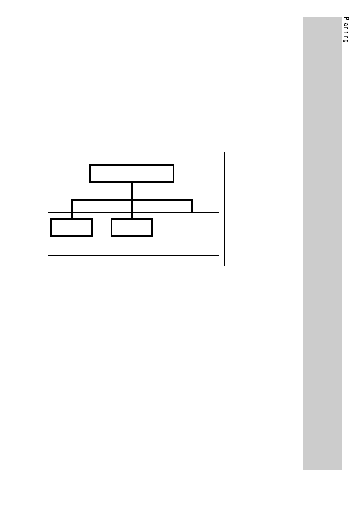
The different PROFIBUS operating modes
PROFIBUS operat. modes
DP operat.
Both PROFIBUS variants have an identical wiring. Their
communication profile, however, is different.
Data are transmitted via RS485 bus (2130IB.V001) or optical fibre
cables (2130IB.V002).
For the complex tasks in power transmission it has become a
necessity for the component suppliers to agree about the most
important device functions and parameters. Therefore, more than 30
international drive manufacturers have come together to form the
DRIVECOM User Group e.V.
Lenze and the other members have brought these functions together
in a so-called profile (DRIVECOM profile power transmission 21) on
the basis of the PROFIBUS standard (part 2). This profile is
implemented on the 2130IB bus interface module 2130IB.
The DRIVECOM profile definition is a useful supplement of
standardardized communication for the user and describes in general
terms the data contents and the controller behaviour.
FMS operat.
Mixed operation
(DP operation
and FMS operation)
7
Page 10

The 2130IB bus interface module has the following features:
• Slave interface module for the communication system PROFIBUS
with the communication profiles
PROFIBUS-FMS and PROFIBUS-DP
• Bus connection according to the RS485 standard (2130IB.V001) or
optical fibre cables according to Siemens SINEC-L2FO
(2130IB.V002).
• Baud rate from 93.75 kBaud to 1.5 MBaud
• Additional module for the Lenze series 4900, 8600 and 9200.
• Can be combined with the automation modules 2211PP, 2212W P
• Standardised parameters and controller functions according to the
DRIVECOM profile 21
• Parameter setting channel as option for PROFIBUS-DP
• Access to all Lenze parameters
• LECOM-A/B interface at the device remains active
• Intelligent module with 16-bit microprocessor
8
L
Page 11
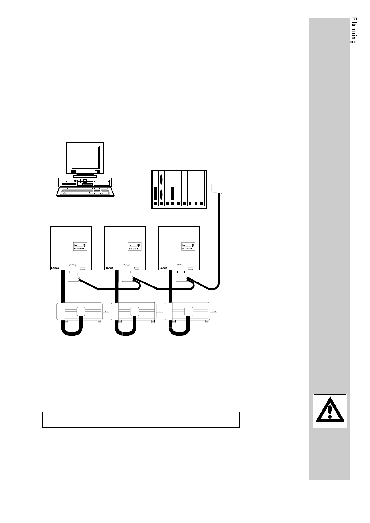
1.1. Structure of the PROFIBUS system
The PROFIBUS network according to DIN 19245 part 1, consists of an
RS485 connection.
As standard, you can connect a maximum of 32 participants (including
hosts) to the RS 485 bus. Using repeaters this structure can be
extended to a maximum of 127 participants in the whole bus system.
The repeaters can also be used to achieve line or tree topologies. The
maximum extension of the bus system depends on the baud rate and
the number of repeaters.
For more information, please consult the documentation of the control
manufacturer.
PROFIBUS using RS485 connection (without repeaters)
Host (Master)
Controller 1 Controller 2 Controller 3
8600
4900
9200
8600
4900
9200
PROFIBUS
LECOM-AB
Motor 1 Motor 3
PROFIBUS
Motor 2
LECOM-AB
8600
4900
9200
PROFIBUS
LECOM-AB
Apart from the RS485 connection you can also use an optical fibre
cabling. Here, the Siemens system SINEC-L2FO is used mainly,
where point-to-point and star connections (using active star
connectors) are possible.
Note:
The module variant 2130IB.V002 has a connection for OFC plastic
fibres for distances from 5 m to 25 m.
9
Page 12
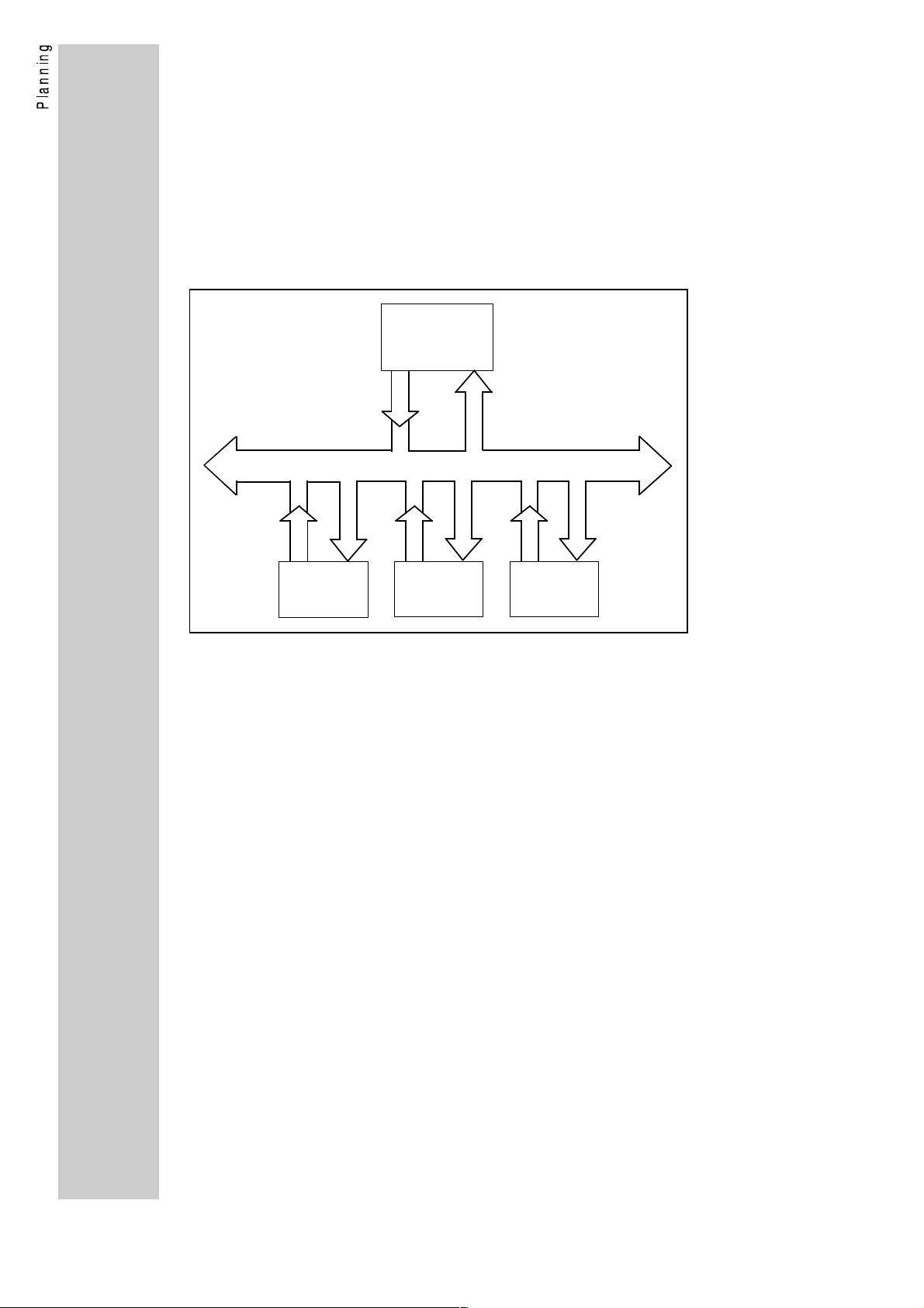
1.1.1. Explanations about PROFIBUS-DP
PROFIBUS-DP is the variant for sensors/actors, when a higher
process response is required. PROFIBUS-DP connects the central
automation devices, like for example programmable logic controllers,
via a fast serial connection using decentral input and output devices,
sensors and actors such as controllers.
The main task of the PROFIBUS-DP system is the fast cyclic data
exchange between the central automation device (master) and the
peripherial devices (slaves); see figure "standard structure".
Standard structure
Master
DP
SlaveSlave
The explanation of the PROFIBUS-DP functions of the Lenze
controller can be obtained from the paragraph "Operating mode
PROFIBUS-DP" (page 35).
Slave
10
L
Page 13
1.1.2. Explanations about PROFIBUS-FMS / mixed operation
PROFIBUS-FMS is the standard PROFIBUS according to part 1 and
part 2 of DIN19245. This operating mode supports the communication
on a bus with several masters (e.g. connected PLC systems) and with
a number of slaves (e.g. controllers). In addition, a mixed bus access
procedure is possible, where several PROFIBUS masters (e.g. PLC
systems) with the same priority can have access to PROFIBUS slaves
(e.g. controllers); see figure "extended structure".
Extended structure
Master
Master
DP, FMS or mixed operation
Slave
PROFIBUS-FMS is based on the description of objects. Devices are
written in as virtual field devices (VFD = virtual field device); with one
device having several VFDs. Parameters or variants are displayed as
objects, which can be read out or written in using the services "Read"
or "Write", when an index (index + subindex) is specified. The FMS
device supplies an object description of every variable or data type
which contains the most important information about the
communication.
Slave
Slave
In a mixed PROFIBUS system, you can operate PROFIBUS-DP
devices and PROFIBUS-FMS devices on the same bus.
In a mixed system, however, only participants with the same
communication profile (FMS or DP) are able to communicate with
each other.
Lenze controllers have both communication profiles. In the operating
mode "mixed operation" PROFIBUS-FMS and PROFIBUS-DP are
active at the same time. This means that in a mixed system the Lenze
controller can be called up by PROFIBUS-FMS masters and
PROFIBUS-DP masters.
A disadvantage of the mixed operation compared with the pure
PROFIBUS-DP operation is the lower protocol efficiency. There are no
disadvantages compared with the pure PROFIBUS-FMS operation.
Therefore, a special operating mode for PROFIBUS-FMS for the
controller is not necessary.
The description of the PROFIBUS-FMS functions of the Lenze
controller can be obtained from the chapter "operating modeOperating
mode PROFIBUS mixed operation (FMS/DP)" (page 46).
11
Page 14
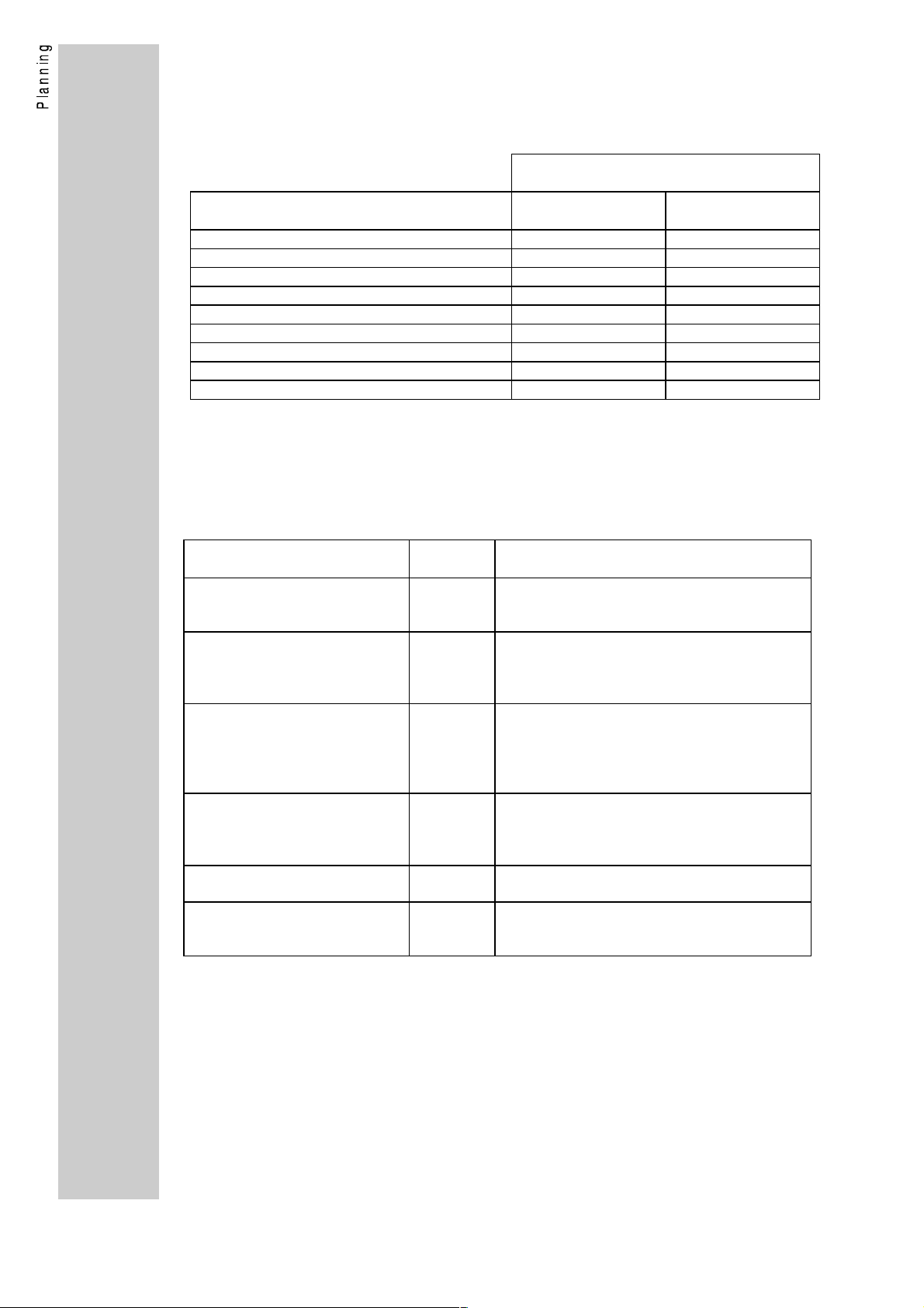
1.2.3. Selection of the PROFIBUS operating mode
Select the desired PROFIBUS operating mode using the following
table.
PROFIBUS operating mode for the
controllers (parameter L-C1900)
Criteria DP operation
(factory setting)
PROFIBUS-DP master available yes yes (DP)
PROFIBUS-FMS master available no yes (FMS)
Several control masters necessary no yes (FMS)
Control of the controller yes yes (FMS/DP)
Parameter setting of the controller yes yes (FMS/DP)
DRIVECOM profile 21 yes yes (FMS/DP)
Baud rate up to 1.5MBaud yes yes (FMS/DP)
Automatic baud rate recognition yes no
Data transmission time / cycle time small medium
Mixed operation
1.2.4. Compatibility with Siemens SINEC-L2
Siemens designates the PROFIBUS communication as SINEC-L2 .
There are a number of variants; their compatibilty with the module
2130IB is listed in the following.
Siemens SINEC-L2 variant Comp. w.
2130IB
SINEC-L2-FMS Yes FMS = "Fieldbus Message Specification"
SINEC-L2-DP (standard) Yes DP = Decentral peripherial units
SINEC-L2-DP (Siemens) No DP = Decentral peripherial units.
SINEC-L2-STF or
SINEC L2-TF
SINEC-L2-Layer2 No Siemens-specific communication of a direct
SINEC-L2-FO Yes Optical fibre cable connection using plastic
No STF = "Siemens Technologische Funktio-
Explanations
Implementation acc. to PROFIBUS standard
DIN 19245 part1 and part 2
Implementation acc. to PROFIBUS standard
DIN 19245 part1 and part 3
(COM ET 200 as of version V4.0)
Older Siemens-specific DP implementations
which are not compatible with the DP
standard
(COM-ET200 up to version V3.x).
onen" (Siemens technological functions).
Siemens-specific
Layer7 implementation
Layer2 access
OFC / HP duplex
Lenze module variant 2130IB.V002.
12
L
Page 15
2. Technical data
2.1. General data
Communication media RS485 (2130IB.V001)
OFC (SINEC-L2FO) (2130IB.V002)
Communication profile PROFIBUS-FMS (DIN 19245 p1+p2)
PROFIBUS-DP (DIN 19245 p1+p3)
PROFIBUS participant Slave
Drive profile DRIVECOM 21
Baud rate [kBit/s] 93.75, 187.5, 500, 1500
Permissible pollution Degree of pollution 2 according to
VDE 110 part 2
Permissible humidity 80% relative humidity no condensation
Surge strength to the bus system 250V AC (2130IB.V001)
infinite (2130IB.V002)
Ambient temperature
2.2. Protocol specific data
2.2.1. PROFIBUS-DP
Max. number of controllers 31 (without repeater)
Supported services Data_Exchange, RD_inp, RD_outp,
Functions available as options Sync, Clear_Data
Maximum PDU length 32 Byte
User data length 12 Byte with DP parameter setting channel
Lenze PNO identification number 0082
Controller master data file for
DIN E 19245 part3
Simatic-S5 COM-ET200/IM 308-B
DP parameter setting data 10100000
Configuration data
with DP parameter setting channel
0...45°C
122 (with repeater)
Slave_Diag, Set_Prm, Chk_Cfg, Get_Cfg,
Global_Control, Set_Slave_add
4 Byte w/o DP parameter setting channel
hex
L_AR0082.GSD
LE0082TD.200
bin
B7
93
hex
hex
(183
(147
dez
dez
),A3
)
hex
(163
dez
),
without DP parameter setting channel
A3
hex
(163
dez
),93
hex
(147
dez
)
2.2.2. PROFIBUS-FMS
Max. number of controllers 31 (without repeater)
126 (with repeater)
Supported services Initiate, Abort, Identify, Status, Get-OV-long,
Read, Write
Maximum PDU length 150 Byte
Communication relations Reference 1: Default Management
Reference 2: MSAC
13
Page 16

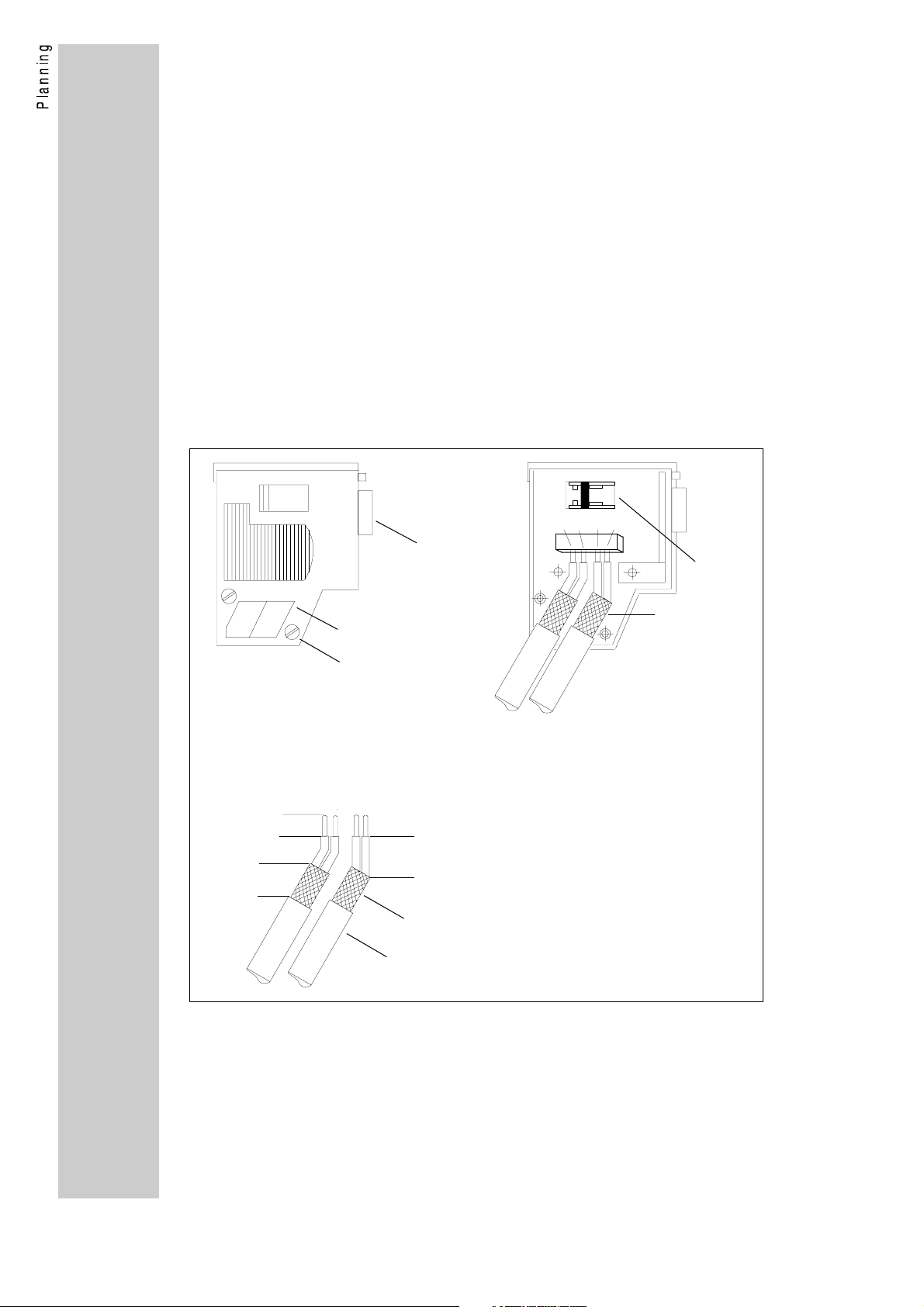
2.3. Dimensions of the 2130IB board
Connections of 2130IB
X12 X13
View of 2130IB with front plate
Explanations:
X4 Automation interface
34-pole plug connector for the
connection with the control board of
the controller
X12 RS485 bus connection
9-pole SubD socket
(only 2130IB.V001)
X13-W30 OFC receiver
(only 2130IB.V002)
X13-W31 OFC transmitter
(only 2130IB.V002)
V1 V2
V1 (LED green) supply 2130
OFF: Module has no supply voltage.
The controller is switched off or the
connection to the controller is
interrupted (X4).
ON: Module has supply voltage.
V2 (LED yellow) Communication
2130
OFF: No supply or 2130 and controller is
not initialized.
ON: Module 2130 and base device are
initialized but there is no
PROFIBUS communication.
FAST FLASHING: (4 times per sec.)
PROFIBUS-DP communication
with user data
SLOW FLASHING: (once per sec.)
PROFIBUS-FMS communication
is established
14
L
Page 17

2.4. Scope of supply
Variants of the 2130IB bus interface module:
Variant Communication medium Service no.
2130IB.V001 RS485 33.2130IB.V001
2130IB.V002 Optical fibre cable Siemens SINEC-
L2FO (plastic OFC/HP duplex)
The scope of supply of the 2130IB module includes the following
components:
• 2130IB board
• Diskette 3 1/2", DOS format 1.44 MByte including:
− INSTALL.EXE Installation program for the following
software
− L_AR0082.GSD Controller master data file according to
DIN E 19245 part 3 (PROFIBUS-DP)
− LE0082TD.200 Controller master data file for
Simatic-S5 COM-ET200/ IM-308B
(SINEC-L2-DP)
− 2130@@ST.S5D Example program for Simatic-S5
− LEMOC2 PC program for parameter setting of the
drive as of version V2.2
• 2130IB operating instructions
on request
The controllers can be supplied as a complete system.
15
Page 18

2.5. Manufacturer's Declaration
We hereby certify that the electronic controllers listed in these
Operating Instructions are control components for variable speed
motors intended to be assembled into machines or to form a machine
together with other components. According to the "Council directive ...
relating to machinery" 89/392/EWG, the controllers cannot be called
machines.
These Operating Instructions give advice and recommendations for
the installation and use of the electronic equipment.
As long as the conformity with the protection and safety guidelines
required by the "Council directive ... relating to machinery"
89/392/EWG and its amendment 91/368/EWG is not proved,
commissioning of the machine is prohibited.
The measures required for typically configured controllers to comply
with the EMC limit values are indicated in these Operating Instructions.
The electromagnetic compatibility of the machines depends on the
method and accuracy of the installation. The user is responsible for
the compliance of the machine with the "Council directive ... relating to
electromagnetic compatibility" 89/336/EWG and its amendment
92/31/EWG.
Considered standards and regulations:
• Electronic equipment for use in electrical power installations and
their assembly into electrical power installations:
DIN VDE 0160, 5.88
• Standards for the erection of power installations: DIN VDE 0100
• Degrees of protection: EN 60529, 10.91
• Base material for printed circuits:
DIN IEC 249 part 1, 10.86; DIN IEC 249 part 2-15, 12.89
• Printed circuits, printed boards:
DIN IEC 326 part 1, 10.90; EN 60097, 9.93
• Creepage distances and clearances:
DIN VDE 0110 part 1-2, 1.89; DIN VDE 0110 part 20, 8.90
• Electrostatic discharge (ESD):
prEN 50082-2, 8.92, IEC 801-2, 9.87 (VDE 0843, part 2)
• Electrical fast transient interference (Burst):
prEN 50082-2, 8.92, IEC 801-4, 9.87 (VDE 0843, part 4)
• Surge immunity requirements: IEC 801-5, 10.93
• Radio interference suppression of electrical equipment and
plants: EN 50081-2, 3.94; EN 55011 (VDE 0875, part 11, 7.92)
• Radio interference suppression of radio frequency equipment
for industrial purposes: VDE 0871, 6.78
16
2.5.1. Application as directed of the 2130IB module
The 2130IB module is an additional module for Lenze controllers of
the 4900, 8600, 9200 series. These controllers are industrial
equipment for use in industrial high power plants. They are designed
for use in machinery to control variable speed drives.
Further notes about the use can be obtained from the operating
instructions of the corresponding controller.
L
Page 19
3. Installation
3.1. Installation
You can integrate the 2130IB bus interface module into the controllers
of the 4900, 8600, 9200 series.
It is also possible to use it together with the Lenze automation module
for positioning (2211PP) and winding applications (2211WP).
If you purchase the bus interface module separately, you will need an
installation kit.
Name Service no. Explanation
Installation kit 86004900/2130IB
Installation kit 9200/2130IB 33.9200_N.V008 Installation kit for the 9200 series
Assembly instructions are included in the installation kits.
Further installation kits for the controllers of the 9200 series can be
obtained on request.
33.4900_N.V013 Installation kit for the 8600 and 4900
series
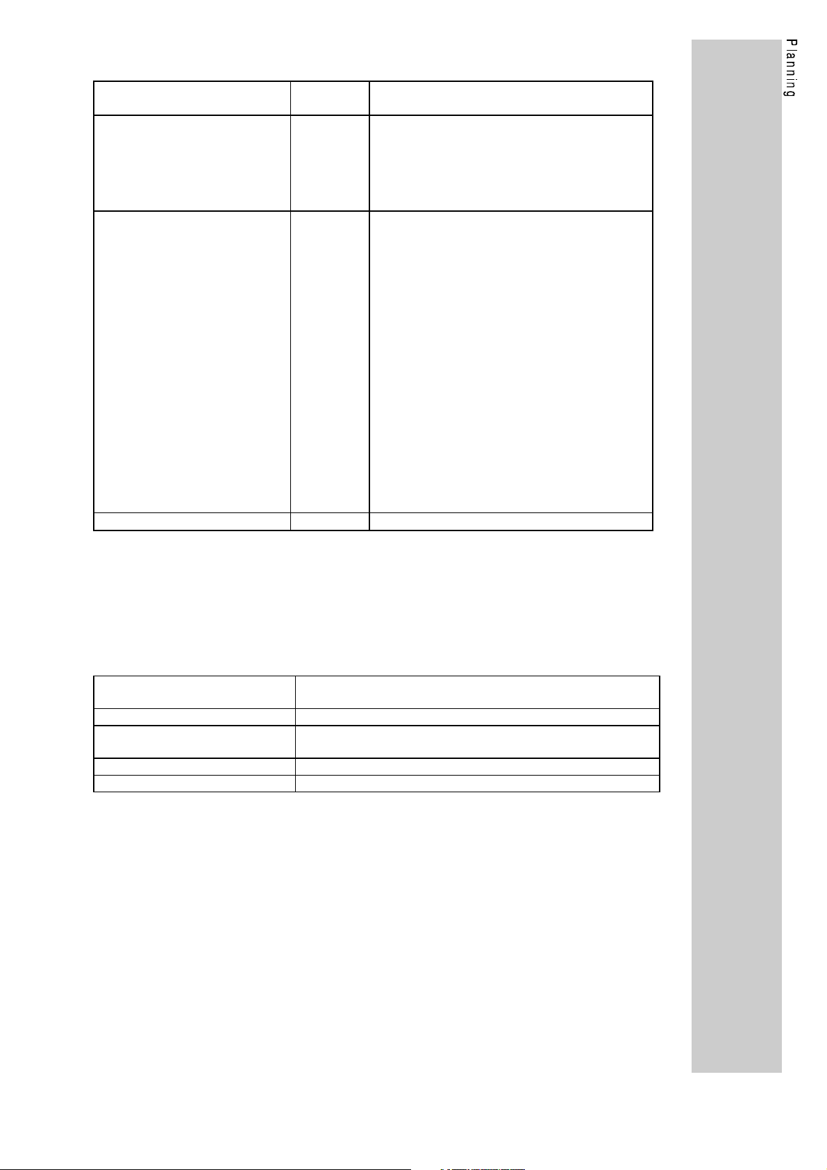
3.2. Wiring
3.2.1. 2130IB.V001 (RS485)
Communication media RS485 (2-wire)
Network topology Line
Number of controllers 31 without repeater. With repeater
max.126.
Maximum cable length 1200 m (depending on the desired baud
rate and cable type. See following cable
specification)
Maximum baud rate 1500 kBaud
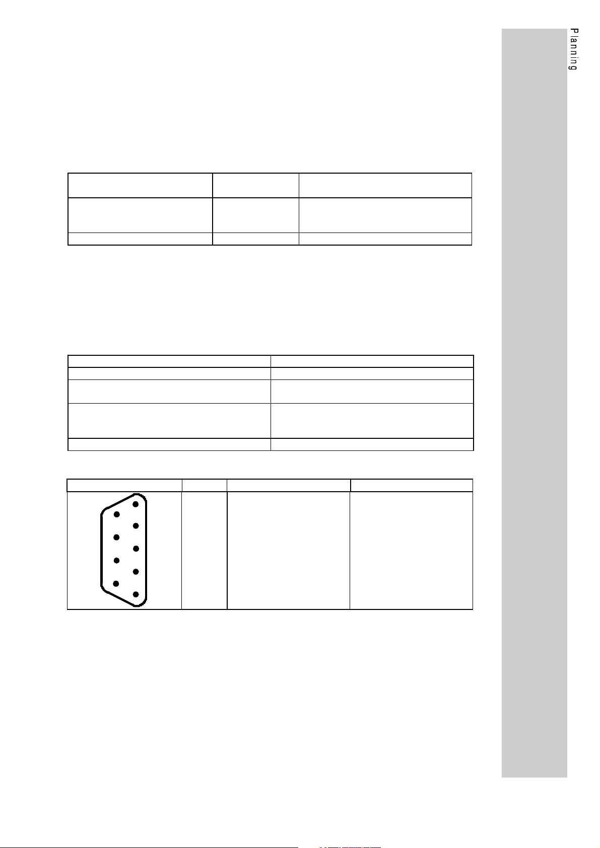
X12 Socket 9-pole SubD (RS485)
View Pin no. Signal name Name
1
5
9
4
8
3
7
2
6
1
2
3
4
5
6
7
8
9
PE
−
RxD / TxD-P
RTS
M5V2
P5V2
−
RxD / TxD-N
−
Protective earth
−
Data line B
Request To Send
Data reference potential
Supply plus
−
Data line A
−
17
Page 20
How to wire the module
• Only use cables according to the following cable specification.
• Observe the following illustrations concerning the bus connector.
• Make the connection to the controllers using the bus connector.
The bus system is not interrupted if you disconnect the plug from
the controller.
• Connect a terminating resistor at the physical bus ends . This
resistor is integrated in the bus connection plug. You can activate it
by using a switch.
• If the 2130IB bus interface module is not supplied with power any
more, the bus system continues to operate. The connected
controller, however, cannot be called by the host.
• If you want to disconnect individual bus participants, make sure that
the terminating resistors at the physical cable ends remain active.
• Further notes and wiring instructions can be obtained from the
documentation of the control manufacturer.
Connection of the bus cable in the bus connector
V
V
1
A
ON
B
B
A
4
approx. 6 mm
approx. 11 mm
V
V
2
3
approx. 11 mm
V
V
bus cable
cable screen
1 = 9-pole SubD connector
2 = Guides for the bus cable
3 = Housing screw
4 = Terminating resistor (not connected))
5 = Cable screen; must lay bare
on the metal guide
V
5
18
L
Page 21
Accessories for the wiring of the RS485 connection
Name Part no. Explanation
Bus connector
Service designation:
Bus connector PROFIBUS
RS485
Cable:
Service designation:
Sinec-L2 bus cable 2-core
Cable resistance
Capacitance per unit length
Loop resistance
Wire diameter
Wire cross-section
Wires
Length
363 695 Bus connector for 9-pole SubD socket with
plug terminals to connect the bus cable. Bus
terminal resistor can be added.
Service designation:
Siemens 6ES5 762-1AA12
363 677
(sold by
the meter)
135 - 165 Ω/km (f = 3 - 20 MHz)
≤ 30 nF/km
<110 Ω/km
>0.64mm
>0.34qmm
double twisted, insulated and screened
1200m at 93.75 kBaud
1000m at 187.50 kBaud
400m at 500.00 kBaud
200m at 1500.00 kBaud
Service designation: Siemens SINEC L2 bus
cable (sold by the meter) 6XV1 830-0AH10
• These service designations and technical data of component
manufacturers other than Lenze may not be the latest
information. Therefore they are to be understood as guidelines
only. Precise data can be obtained from the documentation of
these manufacturers.
3.2.2. 2130IB.V002 (OFC)
Communication media Optical fibre cable (plastic)
HP duplex plug connection
Network topology Point-to-point (star network when using star couplers)
Number of controllers 1 (per star coupler 15-1, number of star couplers in a
cascade depends on the baud rate)
Minimum cable length 5m
Maximum cable length 25m
OFC wiring
• A star coupler is not necessary for the wiring to a drive
controller (point-to-point connection).
• If you want to connect several controllers, you must use star
couplers.
Accessories for wiring using optical fibre cables are available from the
Siemens SINEC-L2FO products.
19
Page 22
3.2.3. Additional procedure for FMS / mixed operation
When using the FMS / mixed operation, some parameters must be set
for the controller and the field bus module, which is only possible by
means of the LECOM1 interface.
For the parameter setting of the controllers using the LEMOC2
program, connect the PC (RS232) and the controller (LECOM1; X6) by
means of a PC system cable.
Name Part no. Explanation
PC system cable 5 m 338 094 System cable 5m between PC (9-pole
socket) and controller
PC system cable 10 m 338 095 System cable 10m between PC (9-pole
socket) and controller
Cable type
Cable resistance
Capacitance per unit length
Length
Wiring of the system cable
Controller
9-pole SubD socket
Pin no.
2 (RxD) 3 (TxD) 2 (TxD)
3 (TxD) 2 (RxD) 3 (RxD)
5 (GND) 5 (GND) 7 (GND)
−
PC or similar
9-pole socket
Pin no.
LIYCY 4 x 0.25mm
screened
< 100 Ω/km
< 140nF/km
≤ 15m
PC or similar
25-pole socket
Pin no.
Only use metallized SubD housings. Connect the screen to the
housings at both ends.
20
L
Page 23

Programming
The programming section using the 2130IB bus interface module is
divided into the following chapters:
• Commissioning
• Code table 2130IB
• PROFIBUS operating modes
• DRIVECOM parameters
• Lenze parameters
• Glossary
Commissioning
This chapter contains important information about the initial
connection of the 2130IB together with a controller base device and
an automation module.
In addition, you will obtain information about the installation of the
LEMOC2 PC program, which is necessary for the parameter
setting of the 2130IB.
Code table 2130IB
In the code table 2130IB those parameters are listed which are
used for the setting of the module and the bus system. You can set
these parameters by means of LECOM-A/B or the LEMOC2 PC
program or PROFIBUS.
PROFIBUS operating modes
This chapter contains information about the selection of the operating
modes PROFIBUS-DP or PROFIBUS mixed operation DP/FMS.
For these operating modes, the required settings of the master and the
controller are described. For PROFIBUS-DP, an example program for
the SIMATIC-S5 is briefly explained.
DRIVECOM parameters
This chapter describes the DRIVECOM profile parameters which
are implemented on the module. These are, among others, the
DRIVECOM states and the status and control word as well as the
configuration of the process data and the monitoring functions for
communication.
Lenze parameters
This chapter describes the access to Lenze parameters in the base
controller or in the automation module.
In addition, the control of the device together with an automation
module is explained.
Glossary
In this chapter, all the important technical terms and abbreviations (e.g.
AIF, PDU, subindex) are explained, which you will find in these operating
instructions.
21
Page 24

1. Commissioning
1.1. Code numbers / Index
The parameters of the controller are addressed by means of numbers.
These numbers are called "index" according to the PROFIBUS system.
Lenze designates them as code numbers .
All Lenze code numbers begin with 0. They are in an index range from
22576 (5830
numbers by the preceeding letters "L-C" (e.g.: L-C000 for Lenze code
number 000).
The conversion for the address method between code number and index
is given on page 67.
) to 24575 (5FFF
hex
1.2. How to install the PROFIBUS software
The attached "Lenze PROFIBUS diskette" contains
important data and programs about parameter setting
and control of the controller using PROFIBUS.
The diskette (3 ½", DOS format, 1.44 MByte) contains
the following files:
Diskette 3 1/2", DOS format 1.44 MByte including:
INSTALL.EXE Installation program for the following
software
L_AR0082.GSD Controller master data file according to
DIN E 19245 part 3 (PROFIBUS-DP)
LE0082TD.200 Controller master data file for
Simatic-S5 COM-ET200/ IM-308B
(SINEC-L2-DP)
2130@@ST.S5D Example program for Simatic-S5
LEMOC2 PC program for parameter setting of the
drive as of version V2.2
). You can recognize Lenze code
hex
To install the software, insert the diskette into the disk
drive. Enter:
a:\install or b:\install
Further information about the installation is provided by
the "install program".
22
L
Page 25

1.3. Commissioning sequence
The initial commissioning of the 2130IB bus interface module together
with a controller and possibly an automation module is divided into the
following phases:
Base setting of the controller
In this phase the controller receives information about additional modules
and the source of the control information.
This setting is possible using the keypad at the controller of the LEMOC2
PC program.
PROFIBUS bus parameters
It is not necessary to set PROFIBUS bus parameters for the operation
with PROFIBUS-DP. With the factory setting, the 2130IB module is set
automatically to the baud rate of the master.
In addition, you can enter the PROFIBUS address via PROFIBUS.
Modified bus parameters are automatically saved permanently.
For PROFIBUS-FMS or PROFIBUS mixed operation, a local setting of
the baud rate and the address is necessary. These parameters can be
set using the LEMOC PC program, which is included on the attached
diskette. For this, make a LECOM-A/B connection for commissioning.
PROFIBUS drive control
The drive system is controlled via PROFIBUS. Control information is
transmitted to the controller, and the controller returns feedback
information to the master.
23
Page 26
1.3.1. Base setting of the drive system
For the base setting, the keypad on the controller or LEMOC2 can be
used.
Setting using the keypad on the controller
1. Inhibit controller (press STP key).
2. Set parameter code set (L-C000) to -2-. Now you have access to
the extended parameter set using the keypad.
Confirm the setting using SH + PRG.
3. Set parameter operating mode (L-C001) to -0- or -1-. Now a
parameter setting is possible via the keypad.
Confirm the setting using SH + PRG.
4. Enter automation module code (L-C370).
For this, set parameter L-C370 to -1- .
With this setting, the controller recognizes the interface module.
Confirm the setting using SH + PRG.
Only required for automation module:
4a.
Set parameter code set (L-C1000) of the automation module to -2-.
Now you have access to the extended parameter set using the
keypad. Confirm the setting using SH + PRG.
Only required for automation module:
4b.
Enter field bus module code (L-C1120).
For this, set parameter L-C1120 to -3-.
With this setting, the controller recognizes the interface module.
Confirm the setting using SH + PRG.
Note:
After the setting, the operation changes automatically to the code number
which was set last in the base controller (e.g. L-C370), since the
operation re-initializes. This, however, does not influence the parameters
which are already set.
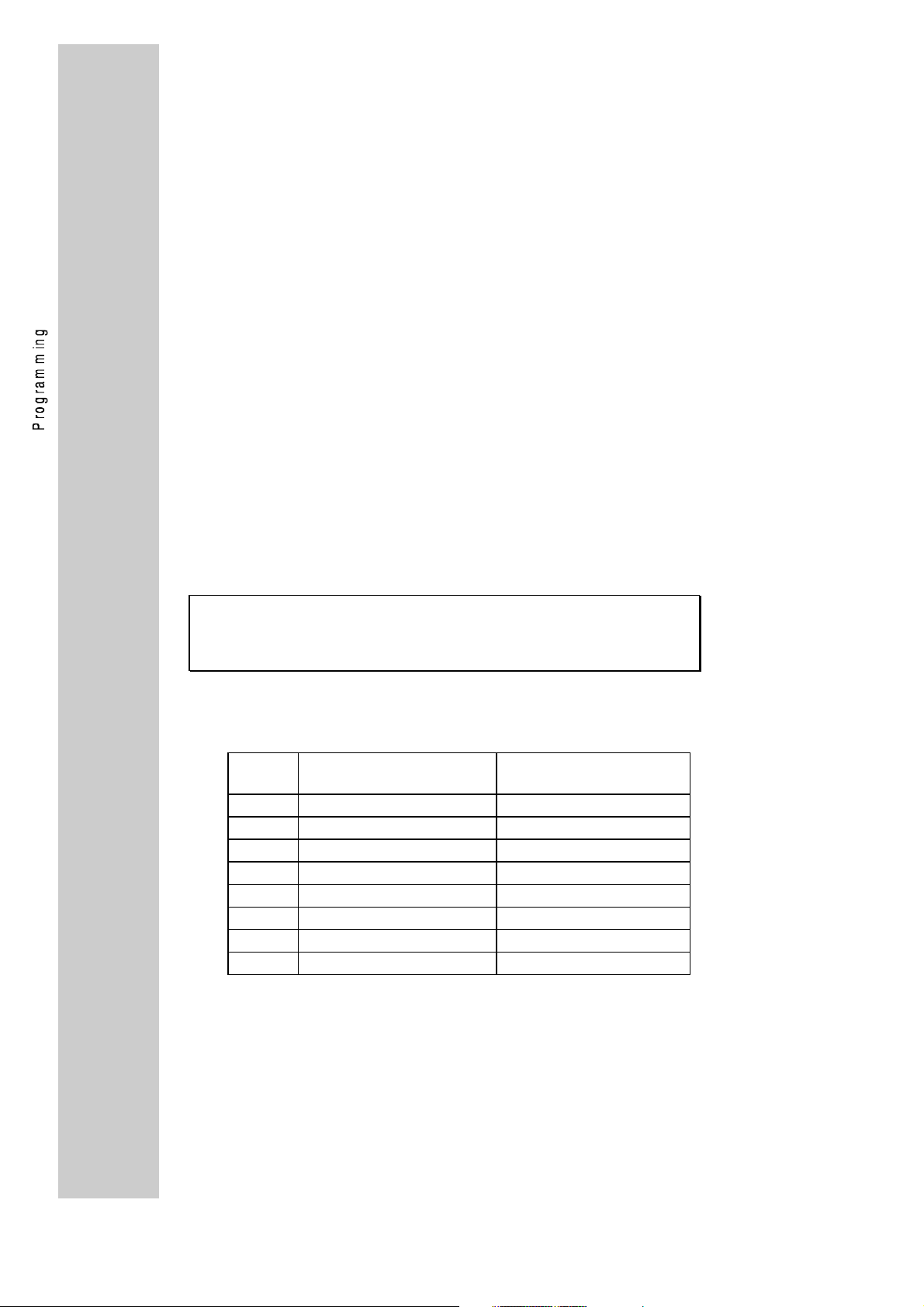
5. Set the operating mode (L-C001).
This setting determines the write access to the drive parameters.
The following combination is effective:
L-C001 Source of parameter
setting
0 Keypad Terminal
1 Keypad Keypad
2 LECOM 1 (LECOM-A/B) Terminal
3 LECOM 1 (LECOM-A/B) LECOM 1 (LECOM-A/B)
4 LECOM 2 (PROFIBUS) Terminal
5 LECOM 2 (PROFIBUS) LECOM 2 (PROFIBUS)
6 Keypad LECOM 2 (PROFIBUS)
7 LECOM 1 (LECOM-A/B) LECOM 2 (PROFIBUS)
For normal operation using PROFIBUS, select 5.
Confirm the setting using SH + PRG.
The read access of LECOM1 (LECOM-A/B) or LECOM2
(PROFIBUS) is possible in any operating mode.
Source of control (e.g.
set-values)
24
L
Page 27

6. To save the setting of L-C001 and L-C370 permanently, set
parameter L-C003 "Save parameter set" to 1 (parameter set 1).
Confirm the setting using SH + PRG.
Only required for automation module:
6a.
To save the setting of the parameter change in the automation
module permanently, save the parameter set (L-C1003 = 1).
Confirm the setting using SH + PRG.
7. Enable the controller (press SH + STP keys). It may be necessary to
undo other controller inhibit sources (terminal 28, TRIP, L-C40).
Note:
If you activate the function "Load factory setting" at the controller, the
settings described under 1 to 7 are deleted.
25
Page 28
Setting using the LEMOC2 PC program
1. Change to your LEMOC2 directory (...\LM2\BIN) and
start LEMOC2 by entering LM2.
2. Load the file "2130_xxx.PDB" (x = serial number)
in the menu "file / controller description".
3. Load a parameter which contains the corresponding factory setting
in the menu "file / load parameter set".
The following parameter sets are available:
2130_FMS.VAR Parameter set for PROFIBUS-FMS or
mixed operation
2130_DP.VAR Parameter set for PROFIBUS-DP
4. Connect your PC to the controller and switch LEMOC2 on-line.
For this, use the option "setting / general settings".
5. Inhibit controller (press STP key or F9 key or use controller inhibit
terminal 28).
6. The 2130IB module can now be activated in the menu
"main menu / drive system"
Set parameter L-C370 (C0370-000) to -1- and transmit the
value to the controller.
Only required for automation module:
6a.
Set parameter L-C1120 (C1120-000) to -3- and
transmit the value to the controller.
Note:
When L-C370 or L-C1120 are modified, the internal interfaces between
the modules are re-initialized. This may result in a delay or refusal of
other services for the time of initialization (max. 30 s). If this is the case,
repeat the service.
7. Set the operating mode with parameter L-C001
(C0001-000), according to the keypad setting, item 5, and transmit
the value to the controller.
8. Save the setting in the controller by setting parameter L-C003 to
-1- and by transmitting the value to the controller.
Only required for automation module:
8a.
Save the setting in the controller by setting parameter L-C1003 to
-1- and transmitting the value to the controller.
9. Enable the controller (press SH + STP keys or F8 key, depending
on item 5). It may be necessary to undo other controller inhibit
sources (terminal 28, TRIP, L-C40).
10. Further information about LEMOC2 and possible error messages
can be obtained from the LEMOC2 help function
(key 1 or "help" menu).
Note:
If you activate the function "Load factory setting" at the controller, the
settings described under 1 to 7 are deleted.
26
L
Page 29

Important notes
Without automation module
• For the 4900 or 8600 series, the freely assignable inputs (Lenze codes
L-C112 and L-C113) must not be assigned to the following functions
with a control using PROFIBUS (L-C001=LECOM2).
− Trip reset
− Ramp generator stop
− Ramp generator input = 0
The reason is that these function are in the DRIVECOM control word
(Index=6040
twice.
) and therefore functions may be inhibited or activated
hex
(L-C112 = 1..n; L-C113 = 3)
(L-C112 = 1..n; L-C113 = 9)
(L-C112 = 1..n; L-C113 = 10)
n = maximum number of
freely assignable inputs
• For configuration (L-C005) using digital frequency input, the speed set-
value is not accepted by the bus system.
With automation module
• When using an automation module, the DRIVECOM profile
parameters are not completely available. Only the DRIVECOM profile
parameters 6000
to 6011
hex
are supported (page 52).
hex
1.3.2. PROFIBUS bus parameters
The PROFIBUS parameters do not have to be changed for the operating
mode PROFIBUS-DP. For PROFIBUS-FMS or PROFIBUS mixed
operation, you can set important parameters like address or baud rate in
the LEMOC2 menu "main menu / PROFIBUS". You can transmit the
parameters to the controller individually or as a whole set (F5 key).
Detailed explanations about the PROFIBUS setting can be obtained from
the chapter "operating mode PROFIBUS mixed operation (FMS/DP) on
page 46 or "operating mode PROFIBUS-DP" on page 35.
27
Page 30

1.3.3. PROFIBUS drive control
Without automation module
1. The controller accepts control and parameter setting data from
PROFIBUS. The controller is controlled by DRIVECOM process
data.
Here you have to distinguish whether the control system (e.g. PLC)
controls to PROFIBUS-DP (page 40) or PROFIBUS-FMS (page 47)
controls the controller.
2. Enable controller
Enable the drive using the DRIVECOM control word and
display the controller states using the DRIVECOM status word
(page 56).
For standard enabling of the controller, proceed as follows:
1. Change to the state "READY TO SWITCH ON
bin
(007E
bin
(007F
bin
POW1 = 0000 0000 0111 1110
2. Wait until state "READY TO SWITCH ON" is reached
PIW1 = xxxx xxxx x01x 0001
3. Change to state "OPERATION ENABLED"
POW1 = 0000 0000 0111 1111
4. Speed set-value (2nd process word; POW2 )
is provided.
PIW = Process input word
POW = Process output word
hex
hex
)
)
28
L
Page 31

Without automation module
1. The controller accepts control and parameter setting data from
PROFIBUS. The controller is controlled by DRIVECOM process
data.
Here you have to distinguish whether the control system (e.g. PLC)
controls to PROFIBUS-DP (page 40) or PROFIBUS-FMS (page 47)
controls the controller. Please note that the operating mode
PROFIBUS-DP is provided as factory setting.
2. Enable controller
Switch on the controller using the automation control word
(page 79) and display the controller states (page 56) using the
automation status word (page 82).
3. For standard enabling of the controller, proceed as follows:
1. Change to state "READY TO SWITCH ON"
POW1 = 0000 0000 0000 1110
(000E
bin
hex
)
2. Wait until state "READY TO SWITCH ON" is reached
PIW1 = xxxx xxxx x01x 0001
bin
3. Change to state "OPERATION ENABLED"
POW1 = 0000 0000 0000 1111
(000F
bin
hex
)
4. Enter other control information in the second process
word (POW2 ).
PIW = Process input word
POW = Process output word
29
Page 32

Communication principle for the access to the controller data
Bus
Controller
PROFIBUS-DP = User data
PROFIBUS-FMS = Read or Write services
Parameter setting channel
from the master
DP = 8 byte
FMS = Read;Write services
Parametrierkanal
to the master
DP = 8 byte
FMS = Read;Write services
Address = Index + Subindex
DRIVECOM-Parameter
PI data description
Index = 6000hex
Process input data
Index = 6010hex
Process output data
Index = 6011hex
Control word
Index = 6040hex
Status word
Index = 6041hex
Nominal speed
Index = 6042hex
Process data
from the master
DP = 4 byte
FMS = not available
Prozeßdatenkanal
to the master
DP = 4 byte
FMS = not available
Process input data
Byte 1
Byte 2
Byte 3
Byte 4
PIW 1
PIW 2
DRIVECOM
Status word (*)
Actual speed (*)
Process output data
Byte 1
POW 1
Byte 2
Byte 3
POW 2
Byte 4
(*) = Assignment with factory setting
PEW = Process input word
PAW = Process output word
DRIVECOM
control word (*)
Nominal speed
value (*)
30
Actual percentage
Index = 6054hex
Lenze parameters
Code set (C0000)
Index = 5FFFhex
Operating mode (C0001)
Index = 5FFEhex
DP parameter sett. channel (C1905)
Index = 588Ehex
L
Page 33

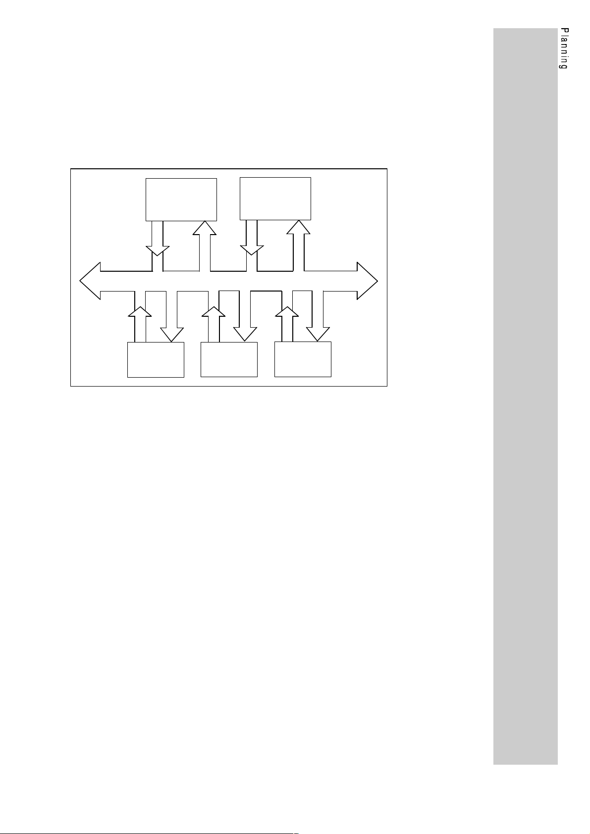
The diagram explains the PROFIBUS access to controller data. Here you
have to distinguish between access to process data and parameter data.
Process data
Process data are data memories where several individual parameters
are combined to form a new parameter: the process data. These
process data are exchanged as fast as possible and cyclically between
the controller and the master. Typical process data are set-value and
control information as well as actual value and status information.
Process data can be divided into process output data (PO data) and
process input data (PI data) and they have a fixed length of 4 byte,
viewed from the master. A summary of parameters is described in the
chapter "process data configuration".
For PROFIBUS-DP, the process data in the user data phase are
permanently exchanged between master and controller. The exact
assignment of the DP user data phase can be obtained from the
chapter "DP user data".
For PROFIBUS-FMS, process data are accessed via parameter
setting using the PROFIBUS services Read or Write. The process
time is considerably longer than for PROFIBUS-DP.The process data
can be accessed under the following index:
Index = 6010hex process input data
Index = 6011hex process output data
Parameter data
Parameters are all DRIVECOM and Lenze controller parameters. A
read and write access is possible for all these parameters. The
parameter is addressed by its index and subindex. The process time in
the controller is considerably longer than the process data access.
For PROFIBUS-DP, the parameters are accessed using the DP
parameter setting channel, which is transmitted cyclically in the user
data. Here, it uses the first 8 byte. The parameter setting channel can
be deactivated using code L-C1905, the DP user data being reduced
by 8 byte.
For PROFIBUS-FMS, the access is possible using the PROFIBUS
services Read or Write.
From the diagram you can see that a parameter which is defined as a
process data value, can be accessed in several ways. The
DRIVECOM parameter, for example, can be directly accessed by its
index 6040hex. It can also be accessed as process output value
(POW1) in the parameter "process output data (index 6011hex). For
PROFIBUS-DP, a direct access using DP user data is also possible.
To avoid write access conflicts, parameters which are process data
must only be changed directly using the user data for PROFIBUS-DP.
For PROFIBUS-FMS, the write access must always be via the
parameter "process output data".
31
Page 34

2. 2130IB code table
In the following, parameters of the 2130IB module are listed which you
can set via the LECOM1 interface (LECOM-A/B).
The parameters listed in the code table are automatically and
permanently saved.
Explanations:
Code: Lenze code number of the parameter. Preceeding
zeros may be omitted.
Name: Name of the parameter
Parameter: Content or meaning of the parameter values.
Parameters printed in bold show the factory setting.
Code
L-C
1810 Software
1900 PROFIBUS
Name Parameter
(Factory setting is printed in bold)
33S2130I_xy000
identification
operating
mode
Software identification of the 2130IB module
x = Software main version
y = Software subversion
-0- DP operation. Only PROFIBUS-DP
-1- Mixed operation. PROFIBUS-FMS and
PROFIBUS-DP services are possible at the
same time
The operating mode defines the masters which are
able to communicate with the controller. In operating
mode 0 only pure DP masters can be used, and in
operating mode 1 the controller can communicate with
DP or FMS masters.
Your
settings
−
Data transmission in operating mode 0 is much more
efficient than in operating mode 1.
When changing the operating mode, codes L-C1903
and L-C1904 are also loaded with the corresponding
factory settings.
1901 Station
address
1902 Baud rate -2- 93.75 kBaud
1903 Baud rate
recognition
126 1 to 126
Number for precise addressing of the drive in the
PROFIBUS network. This number must only be
assigned once in the bus system.
-3- 187.5 kBaud
-4- 500.0 kBaud
-6- 1500.0 kBaud
In the bus system, all participants must have the same
baud rate. In the operating mode DP operation
(L-C1900 = 0) and automatic baud rate recognition
(L-C1903 = 1), this code number has no meaning.
-0- inactive (L-C1900 = 0)
-1- active (L-C1900 = 1)
Automatic baud rate recognition is only possible in DP
operation; i.e. the drive is set automatically to the baud
rate of the master.
32
L
Page 35

Code
Name Parameter
L-C
1904 min T
SDR
1905 DP parameter
setting
channel
(Factory setting is printed in bold)
11 to 255 Bit-times
11 (L-C1900 = 0)
125 (L-C1900 = 1;L-C1902 = 2)
250 (L-C1900 = 1;L-C1902 = 3)
255 (L-C1900 = 1;L-C1902 = 4)
255 (L-C1900 = 1;L-C1902 = 6)
Minimum reaction time of the controller on a telegram
of the master (protocol acknowledgement). The
setting is in bit-times and therefore depends on the
selected baud rate.
Setting is only possible in the PROFIBUS operating
mode mixed operation (L-C1900 = 1).
-0- inactive
-1- active
DRIVECOM parameter setting channel for DP
operation; i.e. DRIVECOM and Lenze parameters can
also be accessed during the user-data phase.
Your
settings
33
Page 36

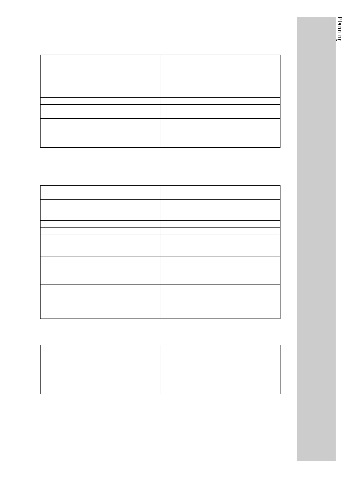
3. PROFIBUS operating mode
The PROFIBUS operating mode determines the participants for the
bus system. We distinguish between two operating modes:
• pure PROFIBUS-DP operation
• mixed operation of PROFIBUS-DP and PROFIBUS-FMS
In the following, criteria for the selection of the suitable operating
mode are listed.
Criteria Code
numbers
PROFIBUS-DP master
exists
PROFIBUS-FMS master
exists
Station address can be set L-C1901 yes
Station address can be set
via bus
Baud rate up to 1.5MBaud L-C1902 yes
Automatic baud rate
setting
DP parameter setting
channel
Data transmission time /
cycle time
The PROFIBUS operating mode is selected under L-C1900.
L-C1900 PROFIBUS
operating
mode
−
−
−
L-C1903 no possible
L-C1905 possible
−
-0- DP operating mode. Only pure PROFIBUS-DP
-1- Mixed operation. PROFIBUS-FMS and PROFIBUS-
Mixed operation
(FS = factory setting)
possible necessary
possible no
FS = 126
no yes
FS = 500 kBaud
FS = active
medium low
DP services are possible at the same time
DP operation
(FS = factory setting)
yes
FS = 126
yes
FS = 500 kBaud
FS = active
possible
FS = active
The selection of the operating mode causes other bus parameters
to be set automatically to the default values of this operating mode
so that, especially for the DP operating mode, further setttings are
not required.
34
L
Page 37

3.1. PROFIBUS-DP operating mode
In the following only the settings for pure PROFIBUS-DP operation are
explained.
Settings for the master
Most of the controller manufacturers demand a controller description
file (controller master data file). Therefore, the following files are saved
in the DOS format on the attached diskette:
File name Meaning
L_AR0082.GSD Controller master data file according to
DIN E 19245 part 3
LE0082TD.200 Controller master data file (type file) for
Simatic-S5 COM-ET200/IM308-B
The master must be set as follows:
Function Setting
(depending on the type of master)
Baud rate 500 kBaud (factory setting)
Value as controller parameter
L-C1902 (page 32).
Communication profile
(Bus profile)
Slave station address
(Station number)
DP configuration data (configuration)
PROFIBUS-DP DIN E 19245 part 3
(DP standard)
Value in controller parameter
L-C1901 = 0 (page 32).
126 (factory setting)
Value as controller parameter
L-C1901 (page 32).
with DP parameter setting channel
(L-C1905=1)
B7
93
hex
hex
(183
(147
dez
dez
),A3
)
hex
(163
dez
),
(factory setting)
A3
hex
(163
dez
),93
hex
(147
dez
)
without DP parameter setting channel
(L-C1905=0)
Lenze PNO identification number 0082
DP parameter setting data 10100000
hex
bin
DP user data length 12 byte (with DP parameter setting
channel)
4 byte (without DP parameter
setting channel)
Setting as controller parameter
L-C1905 (page 32).
35
Page 38

Controller settings
Code Name Parameter
L-C1900 PROFIBUS
operating
mode
You can set the controller from the master via the bus.
The controller has an automatic baud rate recognition
(see L-C1903). If you want to set the controller locally, proceed just
like in the operating mode mixed operation. More detailed
information can be obtained from the chapter "2130IB code table"
(page 32).
-0- DP operation. Only pure PROFIBUS-DP
-1- Mixed operation. PROFIBUS-FMS and PROFIBUSDP services are possible at the same time
36
L
Page 39

3.1.1. Simatic-S5
Lenze controllers comply with the standard of PROFIBUS-DP
participants. For communication with Simatic-S5, the following hardware
and software components are necessary:
• S5 interface module IM308-B as from version 5.
• Programming software COM ET200 as from version 4.0
3.1.1.1. COM-ET200 settings
In the following, specific settings for Lenze controllers are listed when
using the COM-ET 200 program package.
Menu: ET200 system parameters
Bus profile: DP standard
Menu: Configuration
Station type: Lenze 2130 Vxx
For this setting, copy the file LE0082TD.200 from
the diskette to the COM-ET200 directory.
Configuration: User data with DP parameter setting channel
(controller parameter L-C1905 = 1; factory
setting)
0. = 183; 1. = 163; 2. = 147
User data without DP parameter setting channel
0. = 163; 1. = 147
3.1.1.2. Example program
For easier commissioning, an example program in STEP5 is
provided on the attached diskette (file: 2130@@ST.S5D). The
following function modules (FB) are included:
FB182: Process data communication. Simplified control of
the controller. The standard functions of the Lenze
controller are mapped to the DRIVECOM profile.
FB183 Parameter data communication. Support of the DP
parameter setting channel. All DRIVECOM and
Lenze parameters can be read and written.
37
Page 40

3.1.2. Diagnosis data
The controller supplies the following diagnosis data:
Station status_1
(1 byte)
Diagnosis data of the controller part 1
Bit no. Meaning
----------------------------------------------------------------------------------0 Controller available?
0 = controller available
1 = controller not available.
Caution! The other bit information is not
defined.
1 Controller communication status
0 = controller is ready to communicate
1 = controller is not ready to communicate
2 Comparison of configuration data between master and
controller
0 = configuration data identical
1 = configuration data not identical
3 Controller diagnosis
0 = no fault information
1 = fault (TRIP)
4 Invalid service request from the master
0 = no invalid service request
1 = invalid service request
5 Invalid response from the controller
0 = no invalid response
1 = invalid response
6 Status DP parameter setting
(DP service DDLM_Set_Prm)
0 = no fault
1 = fault
7 Information about the source of parameter setting.
0 = parameter setting by the momentary master
1 = parameter setting by another master
38
L
Page 41

Station status_2
(1 byte)
Diagnosis data of the controller part 2
Bit no. Meaning
----------------------------------------------------------------------------------0 Controller requests new parameter setting.
0 = no request
1 = request for new parameter setting, e.g. since the
DRIVECOM parameter setting channel was changed.
1 User data status
0 = Controller is able to supply user data
1 = Controller is not able supply user data, because
e.g. initializing between communication module and
controller is not yet finished.
2 fixed on 1
3 Communication monitoring in the controller
0 = inactive
1 = active
4 not used
5 Controller input data 'frozen' (Sync)
0 = input data not frozen
1 = input data frozen
6 reserved
7 Information, if the controller parameter set is inactive
and the controller was removed from the cyclic user
data transfer
0 = parameter setting active
1 = parameter setting inactive
Station status_3
(1 byte)
Master_Add
(1 byte)
Ident_Number
( 2 byte)
Ext_Diag_Data_1
(1 byte)
Ext_Diag_Data_2
(2 byte)
Diagnosis data of the controller part 3
Bit no. Meaning
----------------------------------------------------------------------------------0 - 6 reserved
7 Overflow of diagnosis information
0 = no overflow
1 = overflow
1 to 126
PROFIBUS station address of the DP master which has set the
controller parameters. If the parameters are not yet set, the
value 255 is returned.
0082
hex
Fixed identification number for Lenze controllers
Bit no. Meaning
----------------------------------------------------------------------------------0 - 5 fixed value 3
6 - 7 fixed value 0
Controller-related diagnosis information. Fault code according to
DRIVECOM profile parameter 603F
hex
.
39
Page 42

3.1.3. DP process data
Process data are data memories where several individual parameters
are combined to form a new parameter, the process data. These
process data are exchanged as fast as possible and cyclically between
the controller and the master.
Process data can be divided into process output data (PO data) and
process input data (PI data), viewed from the master, that means PO
data are input data for the controller. The controller receives control
information from the master and supplies feedback information to the
master. Process data have a fixed length of 4 byte. A summary of
parameters is described in the chapter "process data configuration"
(page 67).
Factory setting of process input data:
Byte no.
(x) = with DP parameter
setting channel
1 (9) Wort1/High-Byte
Bit 8 - 15
2 (10) Word1/Low-Byte
Bit 0 - 7
3 (11) Word2/High-Byte
Bit 8 - 15
4 (12) Word2/Low-Byte
Bit 0 - 7
Automation
module
no
yes
no
yes
Meaning Index
PIW1
DRIVECOM status word
Automation status word
PIW 2
DRIVECOM actual speed
Automation FDO1
6041
58C4
6044
5A98
hex
hex
hex
hex
Factory setting of process output data:
Byte no.
(x) = with DP parameter
setting channel
1 (9) Word1/High-Byte
Automation
module
Meaning Index
POW1
Bit 8 - 15
2 (10) Word1/Low-Byte
Bit 0 - 7
3 (11) Word2/High-Byte
no
yes
DRIVECOM control word
Automation control word
PIW 2
Bit 8 - 15
4 (12) Word2/Low-Byte
Bit 0 - 7
no
yes
DRIVECOM nominal speed
Automation FDI1
Important note
• If a parameter is set to the process output data, such as for example
DRIVECOM control word in the above table, the parameter (e.g. index
6040
) may not be written directly.
hex
6040
58C5
6042
5A9B
hex
hex
hex
hex
40
L
Page 43

3.1.4. DP user data
With PROFIBUS, process data are exchanged cyclically between
master and controller in the user-data phase. In addition to the
process data you can activate a DP parameter setting channel
which will use the first 8 byte of the user data. The data structure is
the same for input and output data, see following tables.
Data structure of user data
Byte
no.
10 PIW1/POW 1 (Low-Byte) Process data
11 PIW2/POW2 (High-Byte)
12 PIW2/POW2 (Low-Byte)
with parameter setting
channel
1Service
2 Subindex Parameter setting
3 Index (High-Byte) channel
4 Index (Low Byte)
5 Data/Error-Byte 1
6 Data/Error-Byte 2
7 Data/Error-Byte 3
8 Data/Error-Byte 4
9 PIW1/POW 1 (High-Byte)
Byte
no.
without parameter setting
channel
1 PIW1/POW 1 (High-Byte)
2 PIW1/POW 1 (Low-Byte) Process data
3 PIW2/POW2 (High-Byte)
4 PIW2/POW2 (Low-Byte)
41
Page 44

3.1.5. DP parameter setting channel
For the DP parameter setting channel, parameter setting and diagnosis
is possible in the user data operation. This enables the access to all
DRIVECOM and Lenze specific parameters.
If the DP parameter setting channel is active
(module parameter L-C1905 = 1), this channel uses the first 8 byte of the
input and output process data. The DP parameter setting channel has
the same structure for both directions of transmission.
Service
(1 byte)
Service and response control for the parameter setting channel
Bit no. Meaning
----------------------------------------------------------------------------------0 - 2 Service. Service to the controller. The bits are only set
by the master. The controller copies this informationi
into its response telegram.
0 = no service
1 = Read service (read data from the controller)
2 = Write service (write data to the controller)
3 reserved
4 - 5 Data length. Data length in the field Data/Error.
0 = 1 byte
1 = 2 byte
2 = 3 byte
3 = 4 byte
6 Handshake. Code that a new service must be
processed. This bit is changed with every new service.
The controller copies the bit into its response telegram.
7 Status. Status information from the controller to the
master with the service confirmation. Using this bit, the
master is informed whether the service was processed
without errors.
0 = Service processed without errors.
1 = Service not processed. An error has occurred. The
data in the field Data/Error are recognized as fault
indication.
Subindex
(1 byte)
Index
(2 byte)
Additional address to an index. If a parameter consists of
several values (e.g. L-C38 = JOG selection; L-C39 = JOG), the
subindex can be used to directly address a value.
Example: subindex 3 addresses JOG 3
Address of a parameter. For DRIVECOM parameters see
chapter "DRIVECOM" (page 52) and Lenze parameter see
chapter "Lenze parameters" (page 77).
The data are filed in the Motorola format:
Byte 3 High Byte
Byte 4 Low-Byte
42
L
Page 45

Data/Error
(4 byte)
Error messages in the Error field (Data/Error):
Parameter value or fault information in case of an invalid
access. The status of bit service/status determines the meaning
of the data field.
Data
Parameter value which has 1 - 4 bytes, depending on the data
format. Strings or data blocks cannot be transmitted. The data
filed in the Motorola format; i.e. first the High byte/word, then the
low byte/word.
Byte 5 high byte 1 ù high word ù
Byte 6 low byte 1 ûú
Byte 7 high byte 2 ù low word ú
Byte 8 low byte 2 ûû
Error
Error code. For description see the following table.
Byte 5 Error-Class
Byte 6 Error-Code
Byte 7 ù Additional-Code (high byte)
Byte 8 û Additional-Code (low byte)
ú double word
ErrorClass
Error-
Code
6 3 0 0 No access
6 5 1 0 Non-permissible service parameter
6 5 1 1 Invalid subindex
6 5 1 2 Data too long
6 5 1 3 Data too short
6 6 0 0 Object is no parameter
6 7 0 0 Object does not exist
6 8 0 0 Data types are not identical
8 0 0 0 Service cannot be executed
8 0 2 0 Service can currently not be executed
8 0 2 1 Cannot be executed because of local control
8 0 2 2 Cannot be executed because of controller status
8 0 3 0 Out of value range or parameter can only be
8 0 3 1 Parameter value too high
8 0 3 2 Parameter value too small
8 0 3 3 Out of range subparameter
8 0 3 4 Value of subparameter too high
8 0 3 5 Value of subparameter too small
8 0 3 6 max. value smaller than min. value
8
8 0 4 2 Process data length exceeded
8 0 4 3 Collision with other values in general
Additional-Code
[
]
hex
0 4 1 Communication object cannot be mapped to
Meaning
changed when controller is inhibited
process data
43
Page 46

The parameter communication with the controller has the following
sequence:
Read service
1. Determine user-data range of the controller; i.e. the location of the
DP user data in the host.
2. Enter address of the desired parameter in the field "index and
subindex" (DP output data)
3. Service/service = Read service and the bit "service/handshake"
must be exchanged (DP output data).
4. Check if the bit "service/handshake" of the DP input data and
DP output data is identical. If this is the case, the reply has been
received. It is useful to implement a time monitoring.
5. Check if the bit "service/status" is set. If this is not the case, the field
"data/error" contains the desired parameter value. If the bit
"service/status" is set, the read service has not been carried out
correctly, and the field "data/error" contains error information.
Write service
1. Determine user-data range of the controller; i.e. the location of the
DP user data in the host.
2. Enter address of the desired parameter in the field "index and
subindex" (DP output data)
3. Enter parameter value in the field "data/error".
4. Service/service = Read service and the bit "service/handshake"
must be exchanged (DP output data).
5. Check if the bit "service/handshake" of the DP input data and
DP output data is identical. If this is the case, the reply has been
received. It is useful to implement a time monitoring.
6. Check if the bit "service/status" is set. If this is the case, the service
has not been carried out correctly, and the field "data/error" contains
error information. Otherwise, the service has been carried out
correctly.
44
L
Page 47

3.1.6. DP command Sync/Unsync
The Sync command is used to 'freeze' the controller process input data.
This means that the controller works with those process data which it has
used during receipt of the Sync command. The controller receives new
data from the master, but it does not use them. Therefore, the master
can load process data in the controller and activate them simultaneously
using a Sync command to one or several drives.
A Sync command can be sent several times. The Unsync command
cancels the Sync command.
Caution! This function also causes the DP parameter setting
channel to be inactive.
3.1.7. DP command Clear_Data
The Clear_Data command is used to the set controller process input data
to 0.
Caution! This function also makes the DP parameter setting
channel inactive.
45
Page 48

3.2. Operating mode PROFIBUS mixed operation (FMS/DP)
In the operating mode mixed operation, the controller can be called up by
an FMS master or by a DP master. In the following, only these settings
for PROFIBUS-FMS are explained, since the operation using
PROFIBUS-DP is explained on page 35. Notes about restrictions of DP
functions in the operating mode mixed operation are given on page 34.
Settings of the master
Function Setting
Communication relation
(Connecting mode)
Slave-LSAP
(Foreign LSAP)
Slave-Password
(Password)
Slave station address
(Foreign L2 address)
Maximum PDU length
(Max. PDU length)
Baud rate 500 kBaud (factory setting)
Settings of the controller
Function Setting
Station address
L-C1901
Baud rate
L-C1902
MSAC
acyclic master-slave connection
2
0
no password function
126 (factory setting)
Value must be the same as the controller
setting in L-C1901 (page 32).
150
Value must be the same as the controller
setting in L-C1902 (page 32).
126 1 bis 126
Number for precise addressing of the drive
in the PROFIBUS network. This number
can only be assigned once per bus system
(page 32).
-2- 93.75 kBaud
-3- 187.50 kBaud
-4- 500.00 kBaud
-6- 1500.00 kBaud
Baud rate. In the bus system, all
participants must have the same baud rate
(page 32).
46
L
Page 49

3.2.1. FMS process data
Process data are data memories where several individual parameters
are combined to form a new parameter, the process data. These
process data are exchanged as fast as possible and cyclically between
the controller and the master. Process data can be divided into
process output data (PO data) and process input data (PI data),
viewed from the master, that means PO data are input data for the
controller. The controller receives control information from the master
and supplies feedback information to the master. Process data have a
fixed length of 4 byte. A summary of parameters is described in the
chapter "process data configuration" (page 67).
Factory setting of process input data:
Byte no. Auto-
mation
module
1 Word1/High-Byte
Bit 8 - 15
2 Word1/Low-Byte
Bit 0 - 7
No
Yes
3 Word2/High-Byte
Bit 8 - 15
4 Word2/Low-Byte
Bit 0 - 7
No
Yes
Meaning Index
PIW1
DRIVECOM status word
Automation status word
PIW 2
DRIVECOM actual speed
Automation FDO1
6041
58C4
6044
5A98
hex
hex
hex
hex
Factory setting of process output data:
Byte no. Auto-
Meaning Index
mation
module
1 Word1/High-Byte
POW1
Bit 8 - 15
2 Word1/Low-Byte
Bit 0 - 7
3 Word2/High-Byte
No
Yes
DRIVECOM control word
Automation control word
PIW 2
Bit 8 - 15
4 Word2/Low-Byte
Bit 0 - 7
No
Yes
DRIVECOM nominal speed value
Automation FDI1
Important note
•
If a parameter is set to the process output data, such as for example
DRIVECOM control word in the above table, the parameter (e.g. index
6040
) may not be written directly.
hex
3.2.1.1. Access to process data
You can reach the process data via the PROFIBUS services "Read" or
"Write" with the following index:
6040
58C5
6042
5A9B
hex
hex
hex
hex
Index = 6010
Index = 6011
Process input data
hex
Process output data
hex
Further information can be obtained from the chapter "process
data" (page 70).
47
Page 50

3.2.2. Communication services
The following FMS communication services are supported by Lenze
controllers:
• Initiate Make connection from master to controller.
• Abort Abort connection
• Status Read status of the controller
• Get-OV Read object dictionary
• Identify Identification of the controller
• Read Reading of parameters
• Write Writing of parameters
All transmission parameters can be obtained from the host descriptions.
The next chapter contains a list of parameter contents which are returned
by the Lenze controllers.
3.2.2.1. Entries in the communication reference list
You must enter the communication reference list entries yourself.
The following entries in a communication reference list can be set up for
the 2130IB:
Communication reference 1 2
Connection type Master-Slave acyclic Master-Slave acyclic
Connection attribute Defined Defined
Remote LSAP 1 2
R/S Address 0 0
Max-PDU Sending-High-Prio 0 0
Max-PDU Sending-Low-Prio 16 150
Max-PDU Receiving-High-Prio 0 0
Max-PDU Receiving-Low-Prio 16 150
Supported Services Request 00 00 00
Supported Services Response 00 10 00
Max. SCC 1 1
Max. RCC 0 0
Max. SAC 0 0
Max. RAC 0 0
CCI 0 0
hex
hex
80 30 00
00 00 00
hex
hex
48
L
Page 51

3.2.2.2. Initiate
The initiate service is used for the logic initiation between two
participants. The controller returns the following parameters:
Value Meaning
Profile-Number:
When using the automation
module:
Password:
Access Groups:
Access Protection Supported:
Version OV
21
hex
0 No profile
0 The password function of PROFIBUS
0 No access groups
TRUE Access protection is supported
Value: 0
DRIVECOM profile of version 1
is not supported
3.2.2.3. Abort
The abort service is used to abort a logic communication.
3.2.2.4. Status
This service supplies status information about the controller.
The following parameters are returned by the controller:
Status Value Meaning
Logical
Status
Physical
Status
Local
Detail
0 ready to communicate
(L-C001 = 5)
1 limited number of services
(L-C001 <> 5)
0 ready for operation
controller state
"OPERATION
ENABLED"
1 partially operational, all
other possible controller
states
Parameter "status word" 24-bit value, which contains the profile
Information about the momentary
operating state (Lenze parameter
L-C001) of the controller concerning
communication.
Information about the momentary
operating state of the controller.
Please refer to controller states in
figure 5.
parameter "status word" (index
6041
Bits 16 to 23 are set to 0.
) in the bits 0 to 15.
hex
3.2.2.5. Get-OV
Listing of object description for every parameter and data type.
49
Page 52

3.2.2.6. Identify
The identify service is used to identify the controller. The controller
supplies the following parameters:
Value Meaning
Name of manufacturer
Name of the controller
Version of the
controller
Name of the controller
Example
Character no. 1 15
Controller name
Base controller (e.g. "8602")
Controller name
Communication module ("2130")
8602 2130 2211
"Lenze" Company´s name as visible
string
Visible string with 15
characters
Visible string with 15
characters
Controller identification
Controller software versions
Controller name
Automation module (e.g. "2211")
Every controller name consists of: 4 characters for the name of the
controller, 1 blank. If a module is not available, this part is filled with
blanks.
Example: "
Controller version
Controller version
Base controllers (e.g. "21000")
Controller version
Communication module (e.g. "01000")
Controller version
Automation module (e.g. "10000")
Every controller name consists of 2 characters for the base version, 2
characters for variant, 1 character for version of variant. If the module is
not available, this part is filled with blanks.
Example: "
8602 2130 "
Example
Character no. 1 15
2100010000 "
210000100010000
50
Base controller: V2.1 /no variant / no variant version
Comm. module: V1.0 /no variant / no variant version
Auto. module: V1.0 /no variant / no variant version
L
Page 53

3.2.2.7. Read / Write
The Read service is used to read parameters. Either the value or a fault
indication is output.
The Write service is used to write parameters. An acknowledgement or a
fault indication are output .
Lenze controllers support the following fault indications:
ErrorClass
Error-
Code
6 3 0 0 No access
6 5 1 0 Non-permissible service parameter
6 5 1 1 Invalid subindex
6 5 1 2 Data too long
6 5 1 3 Data too short
6 6 0 0 Object is no parameter
6 7 0 0 Object does not exist
6 8 0 0 Data types are not identical
8 0 0 0 Service cannot be executed
8 0 2 0 Service can currently not be executed
8 0 2 1 Cannot be executed because of local control
8 0 2 2 Cannot be executed because of controller status
8 0 3 0 Out of value range or parameter can only be
8 0 3 1 Parameter value too high
8 0 3 2 Parameter value too small
8 0 3 3 Out of range subparameter
8 0 3 4 Value of subparameter too high
8 0 3 5 Value of subparameter too small
8 0 3 6 max. value smaller than min. value
8
8 0 4 2 Process data length exceeded
8 0 4 3 Collision with other values in general
Additional-Code
[
]
hex
0 4 1 Communication object cannot be mapped to
Meaning
changed when controller is inhibited
process data
51
Page 54

4. DRIVECOM parameters
4.1. DRIVECOM code table
The following parametes are implemented according to the
standardization of controller parameters in compliance with the
DRIVECOM profile 21:
Index
hex dez
6000 24576 PI data description Ra/W
6001 24577 PO data description Ra/W
6002 24578 PO data enable Ra/W
6010 24592 Process input data Ra n S OS 4 4
6011 24593 Process output data Ra/W n S OS 4 4
603F 24639 Malfunction code Ra
6040 24640 Control word Ra/W POI
6041 24641 Status word Ra PI
6042 24642 Nominal speed Ra/W POI
6043 24643 Speed reference variable Ra
6044 24644 Actual speed Ra PI
6046 24646 Speed-Min-Max-amount Ra/W
6048 24648 Speed acceleration Ra/W
6049 24649 Speed deceleration Ra/W
604A 24650 Speed quick stop Ra/W
604B 24651 Face value factor Ra/W
604D 24653 Pole number Ra/W
604E 24654 Speed reference value Ra/W
604F 24655 Ramp function time Ra/W
6050 24656 Slow down time Ra/W
6051 24657 Quick stop time Ra/W
6052 24658 Nominal percentage Ra/W POI
6053 24659 Percentage reference
6054 24660 Actual percentage Ra PI
Parameter name R/W PCD PS Dat.S
tr.
nRPDS9 13
−
nRPDS9 13
−
nSOS 1 1
−
nSU16 1 2
−
SOS 2 2
−
SOS 2 2
−
SI16 1 2
−
SI16 1 2
SI16 1 2
−
nAU32 2 8
nRRS 2 6
nRRS 2 6
nRRS 2 6
nAI16 2 4
ySU8 1 1
ySU32 1 4
ySU32 1 4
ySU32 1 4
ySU32 1 4
SI16 1 2
−
SI16 1 2
SI16 1 2
−
variable
Ra
−−
−
−
−
−
−
−
−
−
−
−
−−
Data
type
Data
num.
Data
leng.
52
L
Page 55

Meaning
R/W
Read-Write authorization via LECOM2 (PROFIBUS)
Ra Read-only always permitted
Ra/W Reading is always permitted; writing is restricted (e.g. depending on
L-C001 ("operating mode") or operating state (change only after
controller inhibit).
PCD
Mapping to PROFIBUS process data (Index 6010
hex
, 6011
hex
PI Process input data (from controller to host)
PO Process output data (from host to controller)
POI Process input and output data (see PI and PO)
−
SP
y
n
−
Data str.
Process data mapping is not possible
Non-volatile parameter saving
Yes − Parameter will be saved
No − Parameter will not be saved
Parameter depends on the process and is not saved.
Data structure
S Simple variable (simple parameter). The parameter has only one
value. Addressing is only possible with subindex 0.
A Array variable (field parameter). The parameter has several values
which are of the same data type. Direct addressing of single elements
is possible with the subindex.
With subindex = 0 the complete parameter content is addressed.
R Record variable (combined variable). The parameter has several
values, which may have different data types. Direct addressing of the
single elements is possible with the subindex.
With subindex = 0, the complete parameter content is addressed.
)
Data type
BOL Boolean (FALSE = 00
Data type
TRUE = FF
hex
;
I8 Integer8 ( -128 <= x <= 127 )
I16 Integer16 ( -32768 <= x <= 32767 )
I32 Integer32 (-2147483648 <= x <= 2147483647)
U8 Unsigned8 ( 0 <= x <= 255 )
U16 Unsigned16 ( 0 <= x <= 65535 )
U32 Unsigned32 ( 0 <= x <= 4294967295)
OS Unsigned16. 8 bit/byte binary coded
VS Visible-String. Text, coded to ISO 646
PDS Process data description structure (Index 20
the structure see chapter "process data configuration" (page 67)
RS Ramp structure (Index 21
hex
)
Subindex 1: U32 Numerator delta speed in min
Subindex 2: U16 Denominator delta time in seconds
Data num.
Data leng.
Number of parameter elements
Total length of the parameter in byte.
)
hex
). For the description of
hex
-1
53
Page 56

4.2. Controller states
4.2.1. Status diagram of standard control
For standard control you enter the control information via terminal,
keypad or LECOM1 (standard interface LECOM-A/B). The setting is
done using Lenze parameter L-C001 (page 24).
The information about the momentary controller state (blocks) are
contained in the profile parameter "status word" or "automation status
word". Commands in the profile parameter "control word" are switched
off and cannot cause a change of the controller state. The commands to
change the controller states are entered using the corresponding control
inputs (terminal / keypad / LECOM-A/B). These commands are marked
with **.
Status diagram standard control
Switch on devices
TRIP
(fault)
NOT READY TO SWITCH ON
Status word xxxx xxxx x0xx 0000
automatic when
initializing is completed
READY TO SWITCH ON
Status word xxxx xxxx x01x 0001
automatic
SWITCHED ON
Status word xxxx xxxx x01x 0011
RFR**
OPERATION ENABLED
Status word xxxx xxxx x01x 0111
QSP**
RSP**
Malfunction
Status word xxxx xxxx x0xx 1000
V
** means command.
TRIP-Reset**
54
L
Page 57

Controller states Meaning
NOT READY TO SWITCH ON
READY TO SWITCH ON
SWITCHED ON
OPERATION ENABLED
MALFUNCTION
The controller is being initialized and is not yet
ready to operate. It then switches automatically to
the state "READY TO SWITCH ON".
The controller is inhibited (RSP) and waits for the
power stage to be charged. It then changes
automatically to the state "SWITCHED ON".
The controller is inhibited and waits for controller
enable.
The controller is enabled (RFR). In this state, a
pulse inhibit is possible at any time.
The controller is in the state "MALFUNCTION"
(TRIP).
55
Page 58

4.2.2. Status diagram DRIVECOM control
x
With LECOM2 control (Lenze parameter L-C001 = 5, 6 or 7), the
Lenze controller has the standardized controller states according to
the DRIVECOM profile.
The information about the momentary controller status (blocks) is
contained in the profile parameter "status word" t or "automation
status word" . Commands in the profile parameter "control word" or
"automation control word" can cause the controller status to
change. These commands are shown by arrows with the
corresponding command numbers in the following figure.
Status diagram DRIVECOM control
Example: Status.
Switch on devices
NOT READY TO SWITCH ON
Status word xxxx xxxx x0xx 0000
automatic when
initializing is completed
9
SWITCH ON DISABLED
Status word xxxx xxxx x1xx 0000
Disable voltage
xxxx xxxx xxxx xx0x
Shutdown
xxxx xxxx xxxx x110
2
READY TO SWITCH ON
Status word xxxx xxxx x01x 0001
8
Shutdown
xxxx xxxx
xxxx x110
Switch on
xxxx xxxx xxxx x111
3
SWITCHED ON
Status word xxxx xxxx x01x 0011
Enable operation
4
xxxx xxxx xxxx 1111
OPERATION ENABLED
xxxx xxxx x01x 0111
Inhibit ramp generator/Stop ramp generator/Ramp generator zero
QSP terminal
Information by
parameter 'status word'
(Index 6041hex)
Bit 15 .. Bit 0 (binary)
Example: Command
control commands by
parameter 'control word'
(Index 6040hex)
Bit 15 .. Bit 0 (binary)
10
7
6
Shutdown
xxxx xxxx xxxx x110
5
Disable operation
xxxx xxxx xxxx 0111
Quick stop
xxxx xxxx xxxx x01x
MALFUNCT. REACT. ACTIVE
Status word xxxx xxxx x0xx 1111
Malfunction
Status word xxxx xxxx x0xx 1000
Disable voltage
xxxx xxxx xxxx xx0x
Quick stop
xxxx xxxx xxxx x01x
11
QUICK STOP ACTIVE
Status word xxxx xxxx x00x 0111
Malfunction was
13
recognized
automatic when
malfunction reaction
is completed
Malfunction reset
xxxx xxxx 0xxx xxxx
14
xxxx xxxx 1xxx xxx
Disable voltage
12
xxxx xxxx xxxx xx01
or
quick stop
completed
56
L
Page 59

Controller states Meaning
NOT READY TO SWITCH ON
SWITCH ON DISABLED
READY TO SWITCH ON
SWITCHED ON
OPERATION ENABLED
MALFUNCTION REACTION
ACTIVE
MALFUNCTION
QUICK STOP ACTIVE
Commands Meaning
COMMAND 2,6,8
(Shutdown)
(CONT-Bit0 = 0)
COMMAND 3
(Switch on)
(CONT-Bit0 = 1)
COMMAND 4
(Operation enabled)
(CONT-Bit3 = 1)
COMMAND 5
(Disable operation)
(CONT-Bit3 = 0)
COMMAND 7,9,10,12
(Disable voltage)
(CONT-Bit1 = 0)
COMMAND 7,10,11
(Quick stop)
(CONT-Bit2 = 0)
COMMAND 13
(Malfunction/TRIP)
COMMAND 14
(Reset malfunction/TRIP)
(STEU-Bit7 0->1)
The controller is being initialized and is not yet
ready to operate. It then switches automaticaly to
the state "switch-on disabled".
The controller is inhibited (RSP) and waits for
comand 2 (shutdown).
The controller is inhibited (RSP) and waits for
command 3 (switch on).
The controller is inhibited (RSP) and waits for
command 4 (operation enabled)
The controller is enabled (RFR). In this state, a
pulse inhibit is possible any time.
A fault (TRIP) was recognized and an error
response initiated (e.g. controlled deceleration).
The controller is in a state of error (TRIP).
In the state "OPERATION ENABLED" the
command "quick stop" was given. The controller is
decelerated in a controlled way (quick stop ramp).
After deceleration, the controller changes
automatically to "SWITCH ON DISABLED".
Command to change from different states to the
state "READY TO SWITCH ON".
Command to change to the state "SW ITCHED
ON".
Command to change to the state "OPERATION
ENABLED". Controller inhibit is deactivated.
Command to change to the state "SW ITCHED
ON". Controller inhibit is released.
Command to change to the state "SW ITCH ON
DISABLED". Controller inhibit is released.
Command to change to the state "SW ITCH ON
DISABLED".
If the controller was enabled, the controller is
decelerated in a controlled way (quick stop ramp).
The controller has recognized an error.
In case of certain faults, a controller deceleration
may be necessary (depending on the controller).
Once completed, the controller changes to the
state "MALFUNCTION".
Command to acknowledge a fault. The controller
changes to the state "SWITCH ON DISABLED" if
an error is no longer recognized.
57
Page 60

4.2.3. Control word (6040
Data format: Unsigned16
The parameter "control word" is used for the control of the controller. It
contains commands for status changes (see chapter "status diagram
DRIVECOM control" page 56) and other important control commands.
Structure of the parameter "control word":
Bit Name Meaning
0 Switch on Controller states
0 = commands 2,6,8 (controller inhibit)
1 = command 3 (not controller inhibit)
1 Disable voltage Controller states
0 = commands 7,9,10,12 (controller inhibit)
1 = not command disable voltage
2 Quick stop Controller states
0 = command 7,10,11 (quick stop)
1 = not command quick stop
3 Operation enabled Controller states
0 = command 5 (controller inhibit)
1 = command 4 (not controller inhibit)
4 Disable ramp
function generator
5 Stop ramp function
generator
6 Ramp function
generator zero
7 Reset malfunction Reset of an error (TRIP). For this, a bit change from 0 to
8 reserved Reserved for DRIVECOM
9 reserved Reserved for DRIVECOM
10 reserved Reserved for DRIVECOM
1)
1)
Inhibit of ramp function generator.
Quick stop is enabled without the controller leaving its
state.
0 = disable ramp function generator (quick stop)
1 = not disable ramp function generator
Output of the ramp function generator (speed set-value
integrator) is "frozen".
0 = stop ramp function generator
1 = not stop ramp function generator
Input of ramp function generator (speed set-value
integrator) is set to zero. Therefore controlled
deceleration along the set ramp.
0 = ramp function generator zero
1 = not ramp function generator zero
1 is necessary.
hex
)
58
L
Page 61

Bit Name Meaning
11 free 1 For base controllers, mapping to the 4th freely assignable
input
0 = do not activate function
1 = activate function
12 free 2 For 4900/8600controllers, mapping to the 5th freely
assignable input
0 = do not activate function
1 = activate function
13 free 3 For 4900/8600controllers, mapping to the 6th freely
assignable input
0 = do not activate function
1 = activate function
14 free 4 For 4900/8600controllers, mapping to the 7th freely
assignable input
0 = do not activate function
1 = activate function
15 free 5 For 4900/8600controllers, mapping to the 8th freely
assignable input
0 = do not activate function
1 = activate function
1) only for 4900, 8600 series
Important notes:
If the controller has freely assignable inputs (Lenze codes L-C112
and L-C113), you must not assign the following functions to
terminals when the control is via PROFIBUS (LECOM2).
− Trip reset
− Ramp function generator
stop
− Ramp function generator
(L-C112 = 1..n; L-C113 = 3)
(L-C112 = 1..n; L-C113 = 9) n = maximum number of
freely assignable inputs
(L-C112 = 1..n; L-C113 = 10)
input = 0
Code L-C112 is the terminal assignment. Code L-C113 determines
the function.
The individual bit control commands of the control word are not
independent of other bit positions. The following table shows which
bits must be assigned to make the desired command effective.
Control state commands Bits of the control word
15 8 7 0
1 Shutdown
2 Switch on
3 Operation enabled
4 Disable operation
5 Disable voltage
6 Quick stop
8 Reset malfunction
−−−−−−−−−−−−−
−−−−−−−−−−−−−
−−−−−−−−−−−−
−−−−−−−−−−−−
−−−−−−−−−−−−−−0−
−−−−−−−−−−−−−
−−−−−−−−0−−−−−−−
−−−−−−−−1−−−−−−−
11
11
111
1
111
0
0
0
1
1
−
59
Page 62

Several control commands can be given at the same time. Please
note that a bit change of bit0 is necessary to change from the
status "SWITCH ON DISABLED". This function is necessary to
avoid an unintended starting of the drive during switch on.
Control commands Bits of the control word
Bit
4 Disable ramp
function generator
5 Stop ramp function
generator
6 Ramp function
generator zero
11 free 1 ? ? ? ?
12 free 2 ? ? ?
13 free 3 ? ?
14 free 4 ?
15 free 5
free 5
free 4
16 8 7 0
?????
?????
?????
1
??
1
???
1
????
1
−−−−−−
−−−−−
−−−−
1
−−−−
?
−−−−
−−−−
−−−−
−−−−
1111
0
11111
0
111111
0
1111111
1111111
1111111
1111111
1111111
free 3
free 2
free 1
reserved
reserved
reserved
Reset malfunction
Ramp function
generator zero
Stop ramp function
generator
Disable ramp
function generator
Operation enabled
Quick stop
Disable voltage
Switch on
60
Explanation
0 Bit state is 0
1 Bit state is 1
− Bit state is not defined and has no effect
? Since function can be freely assigned, a statement about
interdependance is not possible.
L
Page 63

61
Page 64

4.2.4. Status word (6041
hex
)
Data format: Unsigned16
The parameter "status word" is used to show compact information about the
controller. It contains status information about controller states (page 56) and
further important information.
Structure of the parameter "status word"":
Bit Name Meaning
0 Ready to switch on Controller status information
0 = State at least "READY TO SWITCH ON"
1 = State less than "READY TO SWITCH ON"
1 Switched on Controller status information
0 = State at least "SWITCHED ON"
1 = State less than "SWITCHED ON"
2 Operation enable Controller status information
0 = State at least "OPERATION ENABLE"
1 = State less than "OPERATION ENABLE"
3 Malfunction Controller status information
0 = no malfunction (TRIP)
1 = malfunction (TRIP)
4 Voltage disabled Information about command "Disable voltage" (see "control word").
0 = Command is active
1 = Command is not active
5 Quick stop Information about command "Quick stop" (see "control word").
0 = Command is active
1 = Command is not active
6 Switch-on disabled Controller status information
0 = Status not "SWITCH ON DISABLED"
1 = Status "SWITCH ON DISABLED"
7 Warning Collective warning message
(Not supported by the base controllers at the moment)
0 = No warning
1 = Warning
8 Message Collective message
(Not supported by the base controllers at the moment)
0 = No message
1 = Message
9 Remote Bus access authority, depending on the Lenze parameter "operating
mode" (L-C001)
0 = L-C001 <> 5
1 = L-C001 = 5
10 Face value reached State of speed/frequency deviation
0 = n
1 = n
11 Limit value State of speed/frequency limit
0 = Limit not activated
1 = Limit activated
12 reserved DRIVECOM reserved
13 reserved DRIVECOM reserved
14 free 1 For 4900/8600 mapping on the third freely assignable output
15 free 2 For 4900/8600 mapping on the fourth freely assignable output
set
set
<> n
=n
actual
actual
62
The precise information about the present controller state can only be
obtained by the combination of the controller state information bit
(bit 0, 1, 2, 3, 4, 5, 6). This is shown in the following.
L
Page 65

Controller states Bits of the status word
15 8 7 0
NOT READY TO SWITCH
−−−−−−−−−0−−
ON
SWITCH ON DISABLED
READY TO SWITCH ON
SWITCHED ON
OPERATION ENABLED
MALFUNCTION
MALFUNCTION
−−−−−−−−−1−−
−−−−−−−−−
−−−−−−−−−
−−−−−−−−−
01−0001
01−0011
01−0111
−−−−−−−−−0−−
−−−−−−−−−0−−
REACTION ACTIVE
QUICK STOP ACTIVE
−−−−−−−−−
00−0111
Free 2
Free 1
Reserved
Reserved
Limit value
Set-value reached
0000
0000
1000
1111
Remote
Message
Warning
Switch-on disabled
Quick stop
Disable voltage
Malfunction
Operation enable
Switched on
Ready to switch on
Explanation
0 Bit state is 0
1 Bit state is 1
− Bit state is not defined and has no effect
63
Page 66

4.3. Ramps for quick stop / disable ramp function generator / QSP
4.3.1. Ramp-min function
In the DRIVECOM profile, two ramps are defined for the controller
commands quick stop, disable ramp function generator and the QSP
terminal function (one absolute ramp, one relative ramp). The ramp
min function recognizes the slower ramp and transmits it to the
controller.
Absolute ramp ('speed quick stop')
The ramp flank is determined by the parameters "delta_speed" /
"delta_time". The absolute ramp is deactivated in the factory setting.
Relative ramp ('quick stop time')
The ramp slope is determined by the parameter "delta_time" referred to
the speed-reference (L-C011). This corresponds to the Lenze ramp
function of L-C012 and L-C013.
4.3.2. Speed quick stop (604A
The parameter "speed quick stop" corresponds to the absolute
speed ramp of the deceleration for the control commands "quick
stop", "disable ramp function generator" or the QSP terminal
function. The slope is entered indirectly via the parameter
"delta_speed" / "delta_time". The parameter is mapped to the
ramp-min function via the Lenze quick stop ramp (L-C105). If the
parameter "delta_time"=0, the ramp is switched off.
Index Sub-
index
604A
604A
hex
hex
1RS
2RS
Data
str.
(21
(21
Data
type
U32 0 to 4294967295
)
hex
U16 0 to 65535
)
hex
)
hex
Range/Initialization
0
Delta speed in rpm
0 (ramp is switched off)
Delta time in seconds
64
L
Page 67

4.3.3. Quick stop time (6051
x
E
''(
)
e
4
hex
)
The parameter "quick stop time" corresponds to the relative speed
ramp of the deceleration for the control commands "quick stop",
"disable ramp function generator" or the QSP terminal function.
The deceleration time refers to the parameter "speed reference"
(index = 604E
Slope
Speed referenc
=
'()
Quick stop time'
hex
).
Inde
=
60
hex
=
Index
6051
hex
The parameter is mapped to the ramp-min function via the Lenze
quick stop ramp (L-C105). If the quick stop time = 0, the ramp is
switched off.
Index Sub-
index
6051
hex
0 S U32 0 to 495000 (max L-C105 / 2)
Data
str.
Data
type
Range/Initialization
L-C105 / 2
Delta time in milliseconds
65
Page 68

4.4. Malfunction / Monitoring
4.4.1. Malfunction code (603F
hex
)
Data format: Unsigned16
The malfunction code has an equivalent profile code, if the controller has
recognized a fault (TRIP). The Lenze parameter L-C067 (index 5FBC
hex
)
contains corresponding Lenze error information, possibly with more
detailed information. The Lenze parameters L-C161 - 168 (index 5F5E
- 5F57
) contain the base controller fault history.
hex
hex
The following DRIVECOM malfunction codes can currently be generated:
Lenze
fault
indication
OC 2300 8960 General overcurrent
OC1 2320 8992 Short circuit, overload
OC2 2330 9008 Earth fault
OC3 2213 8723 Overcurrent during acceleration
OC4 2214 8724 Overcurrent during decleration
OC5 2311 8977
OC6 2312 8978 I2t monitoring
OC7 2311 8977
OU1 3211 12817 Overvoltage during deceleration
OUE 3212 12818 Overvoltage fault
LU1 3130 12592 Phase missing
LP1 3130 12592 Phase failure
LP3 3100 12544 Mains failure
FE 3140 12608 Mains frequency fault
LF 3142 12610 Mains frequency too low
OF 3141 12609 Mains frequency too high
OH 4210 16656 Overheat heatsink
OH1 4410 17424 Overheat supply module
OH2 4210 16912 Overheat axis module
OH3 4310 17168 Overheat motor
CE0 8100 33024 Automation interface time monitoring
U15 5111 20753 Vcc15 supply defective
CCr 6010 24592 System failure
Pr 6310 25360 Parameter reset
PEr 6100 24832 Program error
OL 2300 8960 Overload of outputs
SP 7302 29442 Incorrect polarity of feedback source
Sd1 7301 29441 Analog signal source defective
Sd2 7303 29443 Resolver wire breakage
Sd3 7305 29445 Incremental encoder defective
EEr 9000 36864 External trip
UEr 1000 4096 Unknown fault
dEr 7120 28960 Motor malfunction
ACI 3321 13089 Armature circuit interrupted
Hxx 5000 20480 Self test error
150 8000 32768 General process fault
151 8612 34322 Limit switch negative
152 8612 34322 Limit switch positive
153 8611 34321 Following error 1
154 8611 34321 Following error 2
DRIVECOM malfunction code
hex dez
Meaning
I∗t monitoring
I2∗t monitoring
66
L
Page 69

4.5. Process data configuration
The process data configuration is used to combine different parameters
to form a new parameter, in order to transmit this parameter as fast and
cyclically as possible. This is the case, for example, for the parameters
"speed set-value" (index = 6042) and "control word" (index = 6040
which are combined to form process output data (output data of the
master).
The configuration is done using the parameter "process input data
description" (index = 6000
(index = 6001
index = 20
). The data structure (process data description structure;
hex
) of these parameters is shown in the following.
hex
) and "process output data description
hex
Process data description structure
Subindex
Data
type
Meaning
(general) (Byte PCD) (Word PCD) (Double word
1 U8 process data length
value fixed to 4
2 U16 index for 1st PCD byte 1st PCDword 1st PCD Dword
3 U8 subindex for 1st PCD byte 1st PCD word 1st PCD Dword
4 U16 index for 2nd PCD byte 0 = not used 0 = not used
5 U8 subindex for 2nd PCD byte 0 = not used 0 = not used
6 U16 index for 3rd PCD byte 2nd PCD word 0 = not used
7 U8 subindex for 3rd PCD byte 2nd PCD word 0 = not used
8 U16 index for 4th PCD byte 0 = not used 0 = not used
9 U8 subindex for 4th PCD byte 0 = not used 0 = not used
hex
),
PCD)
The table describes the data structure of the parameter and the meaning
of the entries for byte, word, or double word parameters. In the first
subindex, the length of the process data is entered. The next part is a
description of the parameter which is assigned to each byte of the
process data. The description is the address of the parameter, which
consists of index and subindex.
67
Page 70

Byte assignment of the process data
If a word parameter (16 bit) is assigned to the process data, the
parameter address (index, subindex) is entered in the first corresponding
byte. The second byte is not used and must have a 0. For double word
parameters (32 bit), 3 bytes are not used. The configuration can be
modified in common (subindex = 0) or only in parts.
To ensure the data consistency of the process output data (output data of
the master), the parameter "enable process output data" is necessary.
Example 1 −−−− Changing the process input data:
1. Assignment of the 2nd PCD word with the actual percentage (index = 6054
Write (index = 6000
Write (index = 6000
; subindex =6
hex
; subindex =7
hex
; value = 6054
hex
; value = 0
hex
)
hex
) (may be omitted)
hex
Example 2 −−−− Changing the process output data:
1. Inhibit process output data
Write (index = 6002
2. Assignment of the 2nd PCD word with nominal percentage (index = 6052
Write (index = 6001
Write (index = 6001
; subindex =0
hex
; subindex =6
hex
; subindex =7
hex
; value = 0
hex
; value = 6052
hex
; value = 0
hex
)
hex
)
hex
) (may be omitted)
hex
hex
3. Enable process output data
Write (index = 6002
; subindex =0
hex
; value = FF
hex
hex
)
hex
)
)
68
L
Page 71

4.5.1. Process input data description (6000
Data format: Process data description structure (index 20
hex
hex
)
).
For description see page 67.
Description of the process data which the controller transmits to the
master (input data of the master).
The description can be assigned to profile parameters which have the
PCD attribute "PI" or "POI" (page 52) or they can be assigned to Lenze
AIF process data (page 78) or "AIF process data automation module
(page 84). The value of subindex 1 cannot be changed.
Factory setting:
Base controller (4900, 8600, 9200) Automation module (2211PP, 2212WP)
Sub-
index
Value
hex)
(
Meaning Value
(hex)
Meaning
1 04 Number of PCD bytes 04 Number of PCD bytes
2 6041 Status word 58C4 Status word
3 00 Subindex 0 00 Subindex
4 00 empty 00 empty
5 00 empty 00 empty
6 6044 Actual speed 5A98 FDO A1...A16
7 00 Subindex 0 00 Subindex
8 00 empty 00 empty
9 00 empty 00 empty
4.5.2. Process output data description (6001
Data format: Process data description structure (index 20
hex
hex
).
)
For description see page 67.
Description of the process data which the controller receives from the
master (output data of the master). The description can be assigned to
profile parameters which have the PCD attribute "POI" (page 52) or it
can be assigned to Lenze AIF process data (page 78) or "AIF process
data automation module 84). The value of subindex 1 cannot be
changed.
Factory setting:
Base controller (4900, 8600, 9200) Automation module (2211PP, 2212WP)
Sub-
index
Value
hex)
(
Meaning Value
(hex)
Meaning
1 04 Number of PCD bytes 04 Number of PCD bytes
2 6040 Control word 58C5 Control word
3 00 empty 00 empty
4 00 empty 00 empty
5 00 empty 00 empty
6 6042 Actual speed 5A9B FDI E1...E16
7 00 empty 00 empty
8 00 empty 00 empty
9 00 empty 00 empty
69
Page 72

4.5.3. Process output data enable (6002
Inhibiting and enabling of process output data (output data of the
master). More detailed information about the use of the parameter can
be obtained from the chapter "process data configuration" (page 67).
hex
)
Index Sub-
index
6002
hex
0SOS-100
Data
str.
Data.
type
Range / Initialization
Inhibit output data
hex
FF
Enable output data.
hex
4.6. Process data
4.6.1. Process input data (6010
Data format: Unsigned16 with 4 elements
Process data are data memories where several individual parameters
are combined to form a new parameter, the process data. These
process data are exchanged as fast as possible and cyclically between
the controller and the master. Process input data are input data of the
master and thus output data of the controller. The process data have a
fixed length of 4 byte and a summary of parameters is described in the
chapter "process data configuration" (page 67).
Factory setting of the process input data:
Byte no. Auto-
mation
module
1 Word1/High-Byte
Bit 8 - 15
2 Word1/Low-Byte
Bit 0 - 7
3 Word2/High-Byte
Bit 8 - 15
4 Word2/Low-Byte
Bit 0 - 7
No
Yes
No
Yes
Meaning Index
PIW1
DRIVECOM status word
Automation status word
PIW 2
DRIVECOM actual speed
Automation FDO1
hex
)
6041
58C4
6044
5A98
hex
hex
hex
hex
70
L
Page 73

4.6.2. Process output data (6011
hex
)
Data format: Unsigned16 with 4 elements
Process data are data memories where several individual parameters
are combined to form a new parameter, the process data. These
process data are exchanged as fast as possible and cyclically between
the controller and the master. Process output data are output data of
the master and thus input data of the controller. The process data
have a fixed length of 4 byte and a summary of parameters is
described in the chapter "process data configuration" (page 67).
Factory setting of the process output dataFactory setting of
process output data:
Byte no. Auto-
Meaning Index
mation
module
1 Word1/High-Byte
POW1
Bit 8 - 15
2 Word1/Low-Byte
Bit 0 - 7
3 Word2/High-Byte
No
Yes
DRIVECOM control word
Automation control word
PIW 2
Bit 8 - 15
4 Word2/Low-Byte
Bit 0 - 7
No
Yes
DRIVECOM nominal speed value
Automation FDI1
6040
58C5
6042
5A9B
hex
hex
hex
hex
4.7. Speed/Velocity channel
4.7.1. Pole number (604D
The parameter "pole number" exists only for frequency inverters. It
indicates the pole number of asynchronous motors and is used to
convert frequency values to speed values and vice versa. Only even
numbers are possible.
This is shown on Lenze parameter L-C092.
Index Sub-
index
604D
hex
0 S U8 2 to 254
Data
str.
Data
type
)
hex
Range/Initialization
L-C092
71
Page 74

4.7.2. Face value factor (604B
The parameter "face value factor" is used to change the resolution
or the setting range of the set-value input. It consists of numerator
and denominator. The set-value is multiplied by the factor and the
actual values (reference variable, actual vlaue) are multiplied by the
inverse factor.
hex
)
Index Sub-
index
604B
604B
hex
hex
1 A I16 -32768 to 32767
2 A I16 -32768 to 32767
4.7.3. Speed reference value (604E
The parameter "speed reference value" corresponds to the speed
reference for the relative speed parameters such as nominal
percentage, actual percentage and ramp function time. The profile
parameter is mapped to the Lenze parameter L-C011.
A conversion to frequency values is made. The parameter
determines the internal maximum speed, which is also active with
terminal control.
Index Sub-
index
604E
hex
0 S U32 4900: 0...C11/2 (2500 rpm)
Dat.
Str.
Data
str.
Dat.
Typ
Data
type
Range/Initialization
1
Face value factor numerator
1
Face value factor denominator
)
hex
Range/Initialization
8600: 0..C11*60/pole number(14400 rpm)
9200: 0 C11/2 (4000 rpm)
L-C011/2 in rpm
4.7.4. Nominal speed (6042
The parameter "nominal speed" corresponds to the speed setvalue in rpm. The set-value is multiplied by the face value factor
and mapped to L-C380. Changing the set speed also changes the
parameter "nominal percentage".
Index Sub-
index
6042
hex
0 S I16 -32768 to 32767
Dat
str.
Data
type
)
hex
Range/Initialization
L-C380 or (L-C046)
Nominal speed in rpm
72
L
Page 75

4.7.5. Speed reference variable (6043
The parameter "speed reference variable" corresponds to the
output of the ramp function generator (set-value integrator) in rpm.
The reference variable is multiplied by the inverse of the face value
factor and is mapped to L-C381.
hex
)
Index Sub-
index
6043
hex
0 S I16 -32768 to 32767
4.7.6. Actual speed (6044
The parameter "actual speed" corresponds to the actual speed in
rpm. The actual value is multiplied by the inverse of the face value
factors and is mapped to L-C382.
Index Sub-
index
6044
hex
0 S I16 -32768 to 32767
4.7.7. Nominal percentage (6052
The parameter "nominal percentage" corresponds to the nominal
speed in per cent. This parameter is scaled to the speed reference
(100% = 16383). The set-value is multiplied by the face value factor
and is mapped to L-C380. Changing the "nominal percentage" also
changes the parameter "nominal speed". When reading, the
nominal speed is returned, limited to 200%.
Data
str.
Data
str.
Data
type
Data
type
Range/Initialization
L-C381
)
hex
Range/Initialization
L-C382
Actual speed in rpm
)
hex
Index Sub-
index
6052
hex
0 S I16 -32768 to 32767
4.7.8. Percentage reference variable (6053
The parameter "percentage reference variable" corresponds to the
speed reference variable (see speed reference variable) in per
cent. It is scaled to the speed reference (100% = 16383). The
reference is multiplied by the inverse of the face value factor and is
mapped to L-C381.
Index Sub-
index
6053
hex
0 S I16 -32768 to 32767
Data
str.
Data
str.
Data
type
Data
type
Range/Initialization
L-C380
Nominal speed in per cent (100% = 16383)
)
hex
Range/Initialization
L-C381
Speed reference variable in per cent
(100% = 16383)
73
Page 76

4.7.9. Actual percentage (6054
The parameter "actual percentage" corresponds to the actual
speed in per cent. It is scaled to the speed reference
(100% = 16383). The actual value is multiplied by the inverse of the
face value factor and is mapped to L-C382.
hex
)
Index Sub-
index
6054
hex
0 S I16 -32768 to 32767
4.7.10. Speed-min-max-amount (6046
The parameter "speed-min-max-amount" corresponds to the speed
limit of the maximum and minimum speed set-values in rpm.
Caution! This limit is only effective with LECOM2. The speed
limit itself is set by entering the reference speed
(index = 604E
Index Sub-
6046
hex
6046
hex
hex
index
1 A U32 0 to 32000
2 A U32 0 to 32000
Data
str.
).
Data
str.
Data
type
Data
type
Range/Initialization
L-C382
Actual speed in per cent (100% = 16383)
)
hex
Range/Initialization
0
Minimum speed in rpm
L-C011 in rpm
Maximum speed in rpm
74
L
Page 77

4.7.11. Ramps
4.7.11.1. Ramp-min function
In the DRIVECOM profile, there are each two ramps for the nominal
speed, one absolute and one relative ramp.
For the absolute ramp, the slope of the ramp is determined by the
parameter "delta_speed / "delta_time". Absolute ramps in the
DRIVECOM profile are "speed acceleration" and "speed deceleration".
For the relative ramp, the slope of the ramp is determined by the
parameter "delta_time", referred to the speed reference (L-C011). This
corresponds to the Lenze ramp function of L-C012 and L-C013.
Relative ramps in the DRIVECOM profile are acceleration and
deceleration time.
The ramp-min function determines the slower ramp and transmits it to
the controller. The absolute ramps are deactivated in the factory
setting.
4.7.11.2. Speed acceleration (6048
hex
)
The parameter "speed acceleration" corresponds to the absolute
speed ramp of the acceleration. The slope is entered indirectly via
the parameters "delta_speed" / "delta_time". The parameter is
mapped via the ramp-min function to the Lenze acceleration ramp
(L-C012). If the parameter "delta_time" = 0, the ramp is switched
off.
Index Sub-
index
6048
hex
1RS
Data
str.
(21
Data
Range/Initialization
type
U32 0 to 4294967295
hex
)
0
Delta speed in rpm
6048
hex
2RS
(21
U16 0 bis 65535
)
hex
0 (Ramp is switched off)
Delta time in seconds
75
Page 78

4.7.11.3. Speed deceleration (6049
x
E
''(
)
e
4
x
E
''(
)
e
4
The parameter "speed deceleration" corresponds to the absolute
speed ramp of the deceleration. The slope is entered indirectly via
the parameters "delta_speed" / "delta_time". The parameter is
mapped via the ramp-min function to the Lenze deceleration ramp
(L-C012). If the parameter "delta_time" = 0, the ramp is switched
off.
hex
)
Index Sub-
index
6049
6049
hex
hex
1RS
2RS
4.7.11.4. Ramp function time (604F
The parameter "ramp function time" corresponds to the relative
speed ramp of the acceleration. The ramp function time refers to
the parameter "speed reference value" (index = 604E
Slope
The parameter is mapped via the ramp-min function to the Lenze
acceleration ramp (L-C012). With ramp function time = 0, the ramp
is switched off.
Index Sub-
604F
Speed referenc
=
''()
Acceleration time
index
hex
0 S U32 0 to 495000 (max L-C012 / 2)
Data
str.
(21
(21
Data
str.
hex
hex
Data
type
U32 0 to 4294967295
)
U16 0 to 65535
)
Inde
Index F
Data
type
Range/Initialization
0
Delta speed in rpm
0 (Ramp is switched off)
Delta time in seconds
hex
=
60
hex
=
604
hex
Range/Initialization
L-C012 / 2
Delta time in milliseconds
)
).
hex
76
4.7.11.5. Slow down time (6050
The parameter "slow down function time" corresponds to the
relative speed ramp of the deceleration. The ramp function time
refers to the parameter "speed reference value" (index = 604E
Inde
Index
Dat.
Typ
=
=
Slope
The parameter is mapped via the ramp-min function to the Lenze
deceleration ramp (L-C013). With slow down time = 0, the ramp is
switched off.
Index Sub-
6050
Speed referenc
=
''()
Deceleration time
Dat.
hex
index
0 S U32 0 to 495000 (max L-C012 / 2)
Str.
)
hex
60
hex
6050
hex
Range/Initialization
L-C013 / 2
Delta time in milliseconds
hex
).
L
Page 79

5. Lenze parameters
5.1. Lenze code addressing
The access to Lenze parameters is possible. However, the addressing of
the parameter (code number) is shifted and is calculated as follows:
Index = 24575 - LENZE_CODE NO
Index
= 5FFF
hex
Example:
The Lenze parameter L-C001 (operating mode) can be accessed under
the index 24574 (24575 - 1) using PROFIBUS.
5.2. Lenze data types
The possible Lenze parameters with their ranges are listed in the
corresponding operating instructions. The data of the Lenze parameters
are mainly represented in a fixed-point format of dat type Integer 32 with
four digits after the decimal point.
- LENZE_CODE NO
hex
hex
Example1: L-C039 (JOG) = 150.4Hz
Index = 24575 - 39 = 24536
Index 24536 = 1504000
(0016F300
hex
)
dez
Example 2: L-C039 (JOG) = -150.4Hz
Index = 24575 - 39 = 24536
Index 24536 = -1504000
(FFE90D00
hex
)
dez
77
Page 80

5.3. AIF process data base controller
x
x
x
x
At the moment, the following Lenze parameters can be mapped to the
PROFIBUS process channel:
Function Data
type
CP-n
set
I16 POI ±16384 = ±100%
PCD 4900 series
(L-C, index)
Reference: n
(380;5E83)
CP-n
set2
I16 PI ±16384 = ±100%
Reference: n
(381;5E82)
CP-n
actual
I16 PI 16384 = ±100%
Reference: n
(382;5E81)
CP-M
set
116 PI 16384 = ±100%
Reference: M
Function L-C056
(388;5E7B)
CP-M
limit
116 PO 16384 = ±100%
Reference: M
Function L-C047
(388;5E7C)
CP-actual
angle
U16 PI 0 .. 65535
360° = 16384
(391;5E78)
CP-field
current setvalue
CP-additional
set-value
I16 POI 16384 = ±100%
Reference: L-C083
(392;5E77)
I16 PI 16384 = ±100%
Function L-C049
(393;5E76)
CP-FDI1 OS2 POI Bit 0 ... 7
Terminal E1 ... E8
(136,5F77)
CP-FDO1 OS2 PI Bit 0 ... 4
Terminal A1 ... A5
(151,5F68)
max
max
ma
ma
ma
8600 series
(L-C, index)
±16384 = ±100%
Reference: n
max
(380;5E83)
±16384 = ±100%
Reference: n
max
(381;5E82)
±16384 = ±100%
Reference: n
ma
(382;5E81)
---
---
---
--- ---
--- ---
Bit 0 ... 7
Terminal E1 ... E8
(136,5F77)
Bit 0 ... 4
Terminal A1 ... A5
(151,5F68)
9200 series
±26884 = ±100%
Reference: 8000
rpm
(380;5E83)
±26884 = ±100%
Reference: 8000
rpm
(381;5E82)
±26884 = ±100%
Reference: 8000
rpm
(382;5E81)
±32767 = ±100%
Function: L-C056
(387;5E7C)
±32767 = ±100%
Function: L-C047
(388;5E7B)
0 .. 65535
360° = 16384
391;5E78)
---
---
For explanations about the columns "Data type" and PCD" see chapter
"code table DRIVECOM" (page 52).
Further information can be obtained from the operating instructions of the
base controllers.
78
L
Page 81

5.4. Lenze automation module
If you want to use an additional automation module (e.g. 2211PP,
2212WP), please observe the following notes concerning the parameter
setting:
1. During connection (PROFIBUS-FMS service "Initiate"),
0 (no profile) is returned instead of profile number 21.
2. The profile numbers (603F
to 6054
hex
any more.
3. There are two parameters in addition. They have a similar function
as the DRIVECOM profile parameters "control word" and
"status word":
− Automation control word (index = 58C5
− Automation status word (index = 58C4
For more detailed information, please consult the following chapters
"automation control word" and "automation status word".
4. The DRIVECOM status control is achieved.
5. Detailed fault information can only be obtained from the Lenze
parameters. Under the Lenze parameters L-C067 (index 5FBC
for base controllers or L-1067 (index 5BD4
module, the corresponding fault information can be obtained. Under
the Lenze parameters L-C161 - L-C168 (index 5F5E
the fault history of base controllers is stored.
) are not available
hex
)
hex
)
hex
) for the automation
hex
hex
- 5F57
hex
hex
)
)
5.4.1. Automation control word (58C5
hex
)
Data format: Unsigned16
The parameter "automation control word" is used for the control of the
drive system, consisting of a base controller, an automation module and
the PROFIBUS interface module 2130.
The parameter contains important commands about status transitions
and other important control commands.
79
Page 82

Structure of the parameter "automation control word":
Bit Name Meaning
0 Switch on Controller states
0 = command 2,6,8 (controller inhibit)
1 = command 3 (not controller inhibit)
1 Disable voltage Controller states
0 = command 7,9,10,12 (controller inhibit)
1 = not command disable voltage
2 Quick stop Controller states
0 = command 7,10,11 (quick-Stop)
1 = not command quick stop
3 Operation enabled Controller states
0 = command 5 (controller inhibit)
1 = command 4 (not controller inhibit)
4 OM-Contr4
2211: PRG-START
2212: not used
5 OM-Contr5
2211: PRG-RESET
2212: not used
6 OM-Contr6
2211: PRG-STOP
2212: not used
7 Malfunction reset Reset of a fault (TRIP). The bit must be changed from 0 to 1.
8 OM-Contr8
2211: not used
2212: not used
9 OM-Contr9
2211: not used
2212: not used
10 OM-Contr10
2211: not used
2212: not used
11 free 1 Mapping to the 28th freely assignable input (L-1381)
12 free 2 Mapping to the 29th freely assignable input (L-1381)
13 free 3 Mapping to the 30th freely assignable input (L-1381)
14 free 4 Mapping to the 31st freely assignable input (L-1381)
15 free 5 Mapping to the 32nd freely assignable input (L-1381)
Operating mode control function 4 depends on the automation
software package.
0 = inactive
1 = active
Operating mode control function 5 depends on the automation
software package.
0 = inactive
1 = active
Operating mode control function 6 depends on the automation
software package.
0 = inactive
1 = active
Operating mode control function 8 depends on the automation
software package.
0 = inactive
1 = active
Operating mode control function 9 depends on the automation
software package.
0 = inactive
1 = active
Operating mode control function 10 depends on the automation
software package.
0 = inactive
1 = active
0 = do not activate function
1 = activate function
0 = do not activate function
1 = activate function
0 = do not activate function
1 = activate function
0 = do not activate function
1 = activate function
0 = do not activate function
1 = activate function
80
The individual bit-control commands of the control word are not
independent of the other bit positions. The following list shows which bits
you have to assign in which way in order to activate the desired
command.
L
Page 83

Controller state
commands
1 Shutdown
2 Switch on
3 Enable operation
4 Disable operation
5 Disable voltage
6 Quick stop
8 Reset malfunction
free 5
free 4
free 3
free 2
free 1
OM-Stat10
Bits of the control word
16 8 7 0
−−−−−−−−−−−−−
−−−−−−−−−−−−−
−−−−−−−−−−−−
−−−−−−−−−−−−
1
0
11
11
111
111
0
1
−−−−−−−−−−−−−−0−
1
−−−−−−−−−−−−−
0
−
−−−−−−−−0−−−−−−−
−−−−−−−−1−−−−−−−
OM-Stat9
OM-Contr8
Reset malfunction
OM-Contr6
OM-Contr5
OM-Contr4
Enable operation
Quick stop
Disable voltage
Switch on
Several control commands can be given at the same time. Only a bit
change of Bit0 is necessary to change from the status "SWITCH ON
DISABLED". This function is required to avoid inadvertant starting of the
drive during switch on.
Explanation
0 Bit state is 0
1 Bit state is 1
− Bit state is not defined and has no effect
81
Page 84

5.4.2. Automation status word (58C4
hex
)
Data format: Unsigned16
The parameter "automation status word" is used to show compact
information about the drive system. It contains status information of the
controller states and other important information.
Structure of the parameter "automation status word":
Bit Name Meaning
0 Ready to switch on Controller status information
0 = state at least"READY TO SWITCH ON"
1 = state less than "READY TO SWITCH ON"
1 Switched on Controller status information
0 = state at least "SWITCHED ON"
1 = state less than "SWITCHED ON"
2 Operation enabled Controller status information
0 = state at least "OPERATION ENABLED"
1 = state less than "OPERATION ENABLED"
3 Malfunction Controller status information
0 = no malfunction (TRIP)
1 = malfunction (TRIP)
4 Voltage disabled Information about command "disable voltage"
(see "control word").
0 = command is active
1 = command is not active
5 Quick stop Information about command "quick stop" (see "control word").
0 = command is active
1 = command is not active
6 Switch on disabled Controller status information
0 = State not "SWITCH ON DISABLED"
1 = State "SWITCH ON DISABLED"
7 Warning Collective warning; not supported at the moment.
0 = no warning
1 = warning
8 Message Collective message; not supported at the moment.
0 = no warning
1 = warning
9 Remote Bus access authority; depending on the Lenze parameter
"operating mode" (L-C001)
0 = L-C001 <> 5
1 = L-C001 = 5
10 OM-Stat10
2211: not used
2212: not used
11 OM-Stat11
2211: not used
2212: not used
12 OM-Stat12
2211: not used
2212: not used
13 OM-Stat13
2211: not used
2212: not used
Automation status function 10 depends on the automation
software package.
0 = inactive
1 = active
Automation status function 11 depends on the automation
software package.
0 = inactive
1 = active
Automation status function 12 depends on the automation
software package.
0 = inactive
1 = active
Automation status function 13 depends on the automation
software package.
0 = inactive
1 = active
82
L
Page 85

Bit Name Meaning
14 free 1
15 free 2
Mapping to the 31st freely assignable input (L-1384)
0 = do not activate function
1 = activate function
Mapping to the 32nd freely assignable input (L-1384)
0 = do not activate function
1 = activate function
The precise information about the present controller state can only be
obtained by the combination of the controller state information bit (bit 0,
1, 2, 3, 4, 5, 6).
This is shown in the following.
Controller states Bits of the status word
16 8 7 0
NOT READY TO SWITCH ON
SWITCH-ON DISABLED
READY TO SWITCH ON
SWITCHED ON
OPERATION ENABLED
MALFUNCTION
MALFUNCTION REACTION
ACTIVE
QUICK STOP ACTIVE
−−−−−−−−−0−−
−−−−−−−−−1−−
−−−−−−−−−
−−−−−−−−−
−−−−−−−−−
−−−−−−−−−0−−
−−−−−−−−−0−−
−−−−−−−−−
01−0001
01−0011
01−0111
00−0111
0000
0000
1000
1111
free 2
free 1
OM-Stat13
OM-Stat12
OM-Stat-11
OM-Stat10
OM-Stat9
Message
Warning
Switch-on disabled
Quick stop
Disable voltage
Malfunction
Operation enabled
Switched on
Ready to switch on
Explanation
0 Bit state is 0
1 Bit state is 1
− Bit state is not defined and has no effect
83
Page 86

5.4.3. AIF process data automation module
At the moment, the following Lenze parameters can be mapped to the
PROFIBUS process channel:
Automation module
Function Data
type
CPposition
(1385; 5A96)
I32 PI ±1073741824 (±2
act
PCD 2211PP
(L-C, index)
in angle units of the
feedback system
30
2212WP
(L-C, index)
)
CP-FDI1 OS2 POI Bit 0...15
terminal E1...E16
(1381,5A9B)
CP-FDI2 OS2 POI Bit 0...15
terminal E17...E32
(1382,5A9A)
CP-FDO1 OS2 PI Bit 0...15
terminal A1...A16
(1383,5A98)
CP-FDO2 OS2 PI Bit 0...15
terminal A17...A32
(1384, 5A97)
For explanations about the columns "Data type" and PCD" see chapter
"code table DRIVECOM" (page 52).
Further information can be obtained from the operating instructions of the
base controllers.
Bit 0...15
terminal E1...E16
(1381,5A9B)
Bit 0...15
terminal E17...E32
(1382,5A9A)
Bit 0...15
terminal A1 ...A16
(1383,5A98)
Bit 0...15
terminal A17...A32
(1384, 5A97)
84
L
Page 87

6. Glossary
AIF Automation interface. Interface between controller and
automation/field bus modules. Among others, it contains
defined process data.
bin
Bit time
Controller
CRL Communication reference list
Data format
DP Decentral peripherial units.
DP operation
DP master (class 1)
DP master (class 2)
DRIVECOM
FDO freely assignable digital output
FDI freely assignable digital input
FMS Fieldbus Message Specification. PROFIBUS part 2.
Handshake
hex
Index
L-Cxxx
Values in the binary format (0,1). A character marked "x" can
be any binary character.
Value: MSB ... LSB
Transmission of one bit.
General name for frequency inverters (8600 series, servo
drives (9200 series) and DC drives (4900 series).
Data description, consisting of the components data structure
and data type. For the description see chapter "cDRIVECOM"
(page 52).
Inputs/Ouput units which are connected to the central control
via a serial connection.
Operating mode with only DP masters.
DP master which processes the user data transfer with its
assigned DP slaves
DP master which is used as commissioning or diagnosis
devices; normally a programming device.
Group of more than 30 drive manufacturers, creating uniform
communication solutions for power transmission and definition
of drive profiles.
Defined data transmission procedure (achieved by software).
Value in the hexadecimal format (0...9, A, B, C, D, F). A
character marked "x" can be any hexadecimal character.
Value: MSB ... LSB
Parameter number corresponding to the PROFIBUS and
DRIVECOM definitions. See chapter "cDRIVECOM" (page
52) and chapter "Lenze parameters" (page 77). If a parameter
has several values (e.g. for arrays and records), these are
addressed with an additional subindex.
Parameter number according to the Lenze definition (code
number). "xxx" means the Lenze code number. This code
number can only be accessed in the PROFIBUS system via a
conversion (see chapter "Lenze parameters" (page 77).
85
Page 88

LSB Least significant bit
Master
Mixed operation
Mixed device
MSAC
MSB Most significant bit
OFC Optical fibre cable
User data
PO data Process output data
POWx Process output word of PROFIBUS, viewed from the master
PC
PCD
PDU
PI data Process input data
PIWx Process input word of PROFIBUS, viewed from the master
PLC Programmable logic controller such as Siemens SIMATIC S5
PROFIBUS Process Field Bus
PNO PROFIBUS-Nutzerorganisation e.V.
PROFIBUS DP
PROFIBUS-FMS
Profile
Process data
Bus participant with independent sending authority. Masters
are hosts, like PLCs or PCs.
Operating mode, when there are PROFIBUS-FMS and DP
masters
Device which incorporates functions according to PROFIBUSFMS and PROFIBUS-DP. Lenze controllers are mixed devices
on PROFIBUS or so-called Combislaves.
Communication relation between master and slave, acyclic
For PROFIBUS DP: data which are exchanged in cycles
between control and controller
(host); i.e. data from the master to the drive. "x" means the
word address (starting with 1).
Personal computer
see process data
Process Data Unit. User data length of a PROFIBUS telegram
(host); i.e. data from the drive to the master. "x" means the
word address (starting with 1).
Communication standard DIN19245, consisting of part 1, part
2, and part 3
Group for the promotion of PROFIBUS.
Communication standard to DIN 19245
part 1 and part 3 (draft)
DP means "decentral peripherial units"
Communication standard to DIN 19245
part 1 and part 2 (FMS protocol)
The word profile is taken from the communication standard
PROFIBUS (DIN 19245) and describes supplementary or
restrictive regulations which are valid within industries or
device groups.
The DRIVECOM User Group has standardized some
important controller functions in the DRIVECOM profile 21.
Using the 2130 interface module, the Lenze controllers
support the DRIVECOM profile.
For example set-values and actual values of controllers, which
must be transmitted in a very short time. These are small
amounts of data (e.g. two words with DRIVECOM and Lenze),
which are transmitted cyclically. For PROFIBUS, these data
are transmitted in the logic process data channel.
86
L
Page 89

QSP
Repeater
RFR Reglerfreigabe (Controller enable)
RSP Reglersperre (Controller inhibit)
RS485
Slave
Subindex
TD
TRIP
User data
Quick-Stop
Repeaters are used for the regeneration of the bus signals
(RS485) and therefore for an extension of the bus system.
Repeaters are offered, for example, by Siemens.
Interface standard with difference signals
Bus participant which is only allowed to transmit after a
request by the master. Controllers are slaves.
See index
Technical description or operating instructions
Fault
For PROFIBUS DP: data which are exchanged in cycles
between control and controller
87
Page 90

Index
2130IB features 8
2130IB.V001 15
2130IB.V002 15
A
Abort (FMS) 49
AIF 85
AIF process data 78, 84
automation control word 56
Automation control word 79
automation module 79
automation status word 56, 82
B
baud rate 32, 35
baud rate recognition 32
bin 85
Boolean 53
bus cable 19
bus connector 19
bus profile 35
C
C001 24
C1120 24
C1810 32
C1900 32, 34, 36
C1901 32
C1902 32
C1903 32
C1904 33
C1905 33
C370 24
Cable 19
Clear_Data 45
Code addressing 77
code numbers 22
code table 2130IB 32
COM-ET200 37
COM-ET200 12
connecting mode 46
control word 56, 58
controller 85
controller master data file 13, 35
CRL (FMS) 48
D
data format 85
Data leng. 53
Data num. 53
Data str. 53
Data type 53
disable ramp function generator 64
DP 85
DP configuration data 35
DP master (class 1) 85
DP master (class 2) 85
DP operating mode 35
DP operation 34
DP parameter setting channel 33, 42
DP parameter setting data 35
DP user data 41
DP user data length 35
DRIVECOM 52
DRIVECOM code table 52
DRIVECOM control 56
DRIVECOM profile 7
DRIVECOM User Group 7
E
Error message DP 43
F
fault indication (FMS) 51
fault indication Read 51
fault indication Write 51
foreign L2-address 46
foreign LSAP 46
G
Get-OV (FMS) 49
H
hex 85
I
Identify (FMS) 50
index 22
Index 85
Initiate (FMS) 49
Integer16 53
Integer32 53
Integer8 53
88
L
Page 91

L
L-Cxxx 85
LED green 14
LED yellow 14
LEMOC2 20
Lenze code number 22
Lenze data types 77
Lenze parameters 77
LWL-Verdrahtung 19
M
malfunction 66
Malfunction code 66
master 86
min T
mixed device 86
mixed operation 11, 46
Mixed operation 34
monitoring 66
SDR
33
O
OFC 86
OFC receiver 14
OFC transmitter 14
operating mode 24
Q
QSP 64
quick stop 64, 65
R
R/W 53
Ramp-min function 64, 75
Read (FMS) 51
repeater 87
RS485 9, 17
RS485 bus connection 14
S
Simatic-S5 35, 37
SINEC-L2 12
SINEC-L2FO 9
slave 87
software identification 32
software installation 22
standard control 54
station address 32
station number 35
Status (FMS) 49
status word 56, 62
STEP5 program 37
Sync 45
P
Password 46
PC 86
PC system cable 20
PDU 86
PI 53
PIW 28, 29, 40, 47, 70
PLC 86
PNO 86
PNO identification number 13, 35
PO 53
POI 53
POW 28, 29, 40, 47, 71
process data 70
Process data 86
process data configuration 67
process data FMS 47
process input data 70
process input data description 69
process output data 71
process output data description 69
process output data enable 70
PROFIBUS diskette 22
PROFIBUS operating mode 12, 32, 34
PROFIBUS-DP 10, 35
PROFIBUS-FMS 11, 46, 48
PROFIBUS-network 9
profile 86
profile parameter 52
T
terminating resistor 18
U
Unsigned16 53
Unsigned32 53
Unsigned8 53
Unsync 45
V
Visible-String 53
W
Wiring 18
Write (FMS) 51
X
X12 17
89
Page 92

90
L
 Loading...