

ASPL 13.1003
.Hòh
Anschlussplan
Wiring diagram
M....
Ä.H`hä
13.12
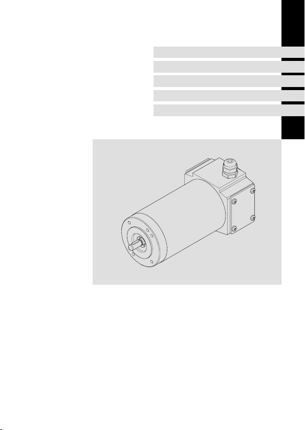
Gleichstrom-Permanentmagnetmotoren
DC permanent-magnet motors

0Abb.0Tab. 0
Lesen Sie zuerst diese Anleitung, bevor Sie mit den Arbeiten beginnen!
Diese Anleitung ist nur gültig zusammen mit der Gesamtdokumentation des
Grundgerätes und des Motors!
Tipp!
Informationen und Hilfsmittel rund um die Lenze-Produkte finden Sie im
Download-Bereich unter
http://www.Lenze.com
Gefahr!
Wenn Sie die folgenden grundlegenden Sicherheitsmaßnahmen missachten,
kann dies zu schweren Personenschäden und Sachschäden führen:
Warnschilder beachten!
Symbol Beschreibung
Lebensgefährliche Spannung: Alle Leistungsanschlüsse, auch bei gezoge-
nem Stecker - Restspannung > 60 V!
Verbrennungsgefahr: Während und nach dem Betrieb sind die Oberflächen
bis zu 140°C heiß! Berührschutz vorsehen!
ASPL 13.1003 DE/EN 1.0
2

Sicherheitshinweise
ƒ Lenze-Antriebs- und Automatisierungskomponenten ...
... ausschließlich bestimmungsgemäß verwenden.
... niemals trotz erkennbarer Schäden in Betrieb nehmen.
... niemals technisch verändern.
... niemals unvollständig montiert in Betrieb nehmen.
... niemals ohne erforderliche Abdeckungen betreiben.
... können während und nach dem Betrieb - ihrer Schutzart entsprechend - spannungsführende, auch bewegliche oder rotierende Teile haben. Oberflächen können heiß sein.
ƒ Alle Vorgaben der beiliegenden und zugehörigen Dokumentation beachten.
Dies ist Voraussetzung für einen sicheren und störungsfreien Betrieb sowie für das Erreichen der angegebenen Produkteigenschaften.
ƒ Alle Arbeiten mit und an Lenze-Antriebs- und Automatisierungskomponenten darf
nur qualifiziertes Fachpersonal ausführen.
Nach IEC 60364 bzw. CENELEC HD 384 sind dies Personen, ...
... die mit Aufstellung, Montage, Inbetriebsetzung und Betrieb des Produkts vertraut
sind.
... die über die entsprechenden Qualifikationen für ihre Tätigkeit verfügen.
... die alle am Einsatzort geltenden Unfallverhütungsvorschriften, Richtlinien und Gesetze kennen und anwenden können.
ƒ Lebensgefährliche Spannung an den Leistungsanschlüssen, auch bei abgezogenem
Stecker: Restspannung >60 V!
ƒ Vor Arbeiten an den Leistungsanschlüssen Motor und wenn vorhanden
Antriebsregler unbedingt vom Netz trennen und warten, bis der Motor stillsteht
(Spannung bei drehendem Motor an den Kontakten).
ƒ Verbrennungsgefahr!
– Während des Betriebs heiße Oberflächen bis 140 °C! Berührschutz vorsehen.
ƒ Verletzungsgefahr durch drehende Welle!
– Vor Arbeiten am Motor warten bis Motor stillsteht.
ƒ Ausführung mit Stecker:
– Stecker niemals unter Spannung ziehen! Der Stecker kann sonst zerstört werden.
– Vor Abziehen des Steckers Spannungsvorsorgung abschalten bzw. Antriebsregler
sperren.
ASPL 13.1003 DE/EN 1.0
3

Bestimmungsgemäße Verwendung
Niederspannungsmaschinen sind keine Haushaltsgeräte, sondern als Komponenten ausschließlich fürdieWeiterverwendungzurgewerblichenNutzungbzw. professionellen Nutzung im Sinne der IEC/EN 61000-3-2 bestimmt.
Sie entsprechen den harmonisierten Normen der Reihe IEC/EN 60034.
Niederspannungsmaschinen sind Komponenten zum Einbau in Maschinen im Sinne der
Maschinenrichtlinie2006/42/EG.DieInbetriebnahmeist solange untersagt, bis dieKonformität des Endprodukts mit dieser Richtlinie festgestellt ist (u. a. IEC/EN 60204-1 beachten).
Niederspannungsmaschinen in Schutzart IP23 oder geringer nicht ohne besondere Schutzmaßnahmen im Freien verwenden.
Die eingebauten Bremsen nicht als Sicherheitsbremsen verwenden. Es ist nicht auszuschließen, dass durch nicht zu beeinflussende Störfaktoren das Brems-Drehmomentreduziert sein kann.
ƒAntriebe
– ... dürfen nur unter den in dieser Dokumentation vorgeschriebenen
Einsatzbedingungen und Leistungsgrenzen betrieben werden.
– ... erfüllen die Schutzanforderungen der EG-Richtlinie ”Niederspannung”.
Eine andere oder darüberhinausgehende Verwendung gilt als sachwidrig!
Nicht bestimmungsgemäße Verwendung
ƒ Motorennicht einsetzen
– ... in explosionsgeschützten Bereichen
– ... in aggressiver Umgebung (Säuren, Gase, Dämpfe, Stäube, Öle)
– ... unter Wasser
– ... unter Strahlung
ASPL 13.1003 DE/EN 1.0
4
Montagehinweis
ƒ Vor dem Transport
– kontrollieren, dass alle Transportsicherungen montiert sind,
– alle Transporthilfen festziehen.
Hinweis!
Keine zusätzlichen Lasten am Produkt anbringen, da die Transporthilfen
(z.B.RingschraubenoderTragbleche) nur für das Gewicht des Motors
ausgelegt sind (Gewicht s. Katalog).
ƒ Zum Transport Traghilfen benutzen!
ƒ Nicht auf die Welle schlagen! Motor kann zerstört werden! Abtriebselemente nur
über Gewinde in der Motorwelle montieren, mit Abziehwerkzeug demontieren.
Kupplung fest anziehen.
ƒ Motor sicher befestigen, für ungehinderte Belüftung sorgen.
ƒ Überwurfmuttern der Stecker fest anziehen.
ƒ Motor sorgfältig erden, Verdrahtung kontrollieren.
ƒ Schirme der Motorleitung großflächig am Motor und am Antriebsregler auflegen.
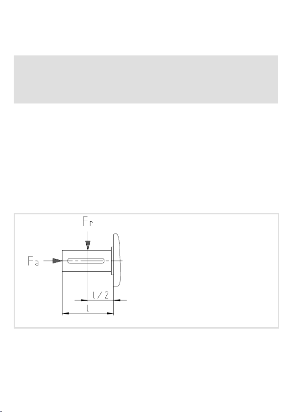
Wellenbelastungskräfte
DieinTabellen(6) genannten zulässigen Belastungen sind entweder als Radialkräfte
oder als Axialkräfte zu verstehen.
Abb. 1 Angriffspunkte von Radial- und Axialkräften
ASPL 13.1003 DE/EN 1.0
5
K12.311-08

Kenndaten
Motorreihe PM-Motoren Typ 13.120
Motortyp P
13.120.35
13.120.45
13.120.55
13.120.65
13.120.75
Tab. 1 Kenndaten bei Standardausführung
Formelbezeichnungen
P
n
n
n
M
n
J Massenträgheitsmoment U
I
n
I
max
n
r/min
3000
n
M
n
NmJkg/
0.17 0.46
1.72
1.91
n
W
55
110 0.35 1.03
200 0.64 3.8
370 1.18 10.7
540
600
cm
16.8
2
U
24
180
24
180
24
180
24
180
24
160274.5
Bemessungsleistung F
Bemessungsdrehzahl F
Bemessungsdrehmoment m
Bemessungsstrom R
Zulässiger Spitzenstrom L
V
A
I
A
3.7
0.46415.0
6.7
0.86446
11.8
1.4719
18.6
2.59011.2
r
a
Mot
A
A
A
I
n
max
A
130200.06
zul. Radiallast
zul. Axiallast
Motorgewicht (Masse)
Ankerspannung
Ankerwiderstand
Ankerinduktivität
R
A
Ohm
1.3682
0.46
27.4
0.19
9.8
0.09
4.1
1.6
L
A
mH
220 200 1.4
98
1.4
320 280 2.4
52
0.54
340 280 3.7
31.5
0.4
580 330 8.0
25
0.2
570 460 10.2
9
F
F
m
r
a
N
Mot
N
ca. kg
ASPL 13.1003 DE/EN 1.0
6

Emissionen
Gefahr!
Abhängig vom Betriebszustand werden hohe Oberflächentemperaturen
erreicht!
ƒ Verbrennungsgefahr beim Berühren.
– Oberflächentemperatur der Motoren bis 95°C
ƒ Gegebenenfalls Berührschutz vorsehen.
ƒ Ein Grenzwert von 70dB (A) wird im Nennbetrieb nicht überschritten. Bei
Wechselstrommotoren können sich Betriebszustände einstellen, bei denen höhere
Geräuschemissionen auftreten.
ƒ Der Kohlebürstenabrieb im Motorinneren der GN- und PM-Motoren setzt sich aus
verschiedenen Metallen, Graphit u. U. Epoxidharz oder anderen Bindemitteln
zusammen.
Elektrischer Anschluss
Wichtige Hinweise
Gefahr!
ƒ Elektrischen Anschluss nur von Elektro-Fachpersonal durchführen lassen!
ƒ Alle Anschlussarbeiten nur im spannungslosen Zustand vornehmen!
Gefahr von ungewollten Anläufen oder elektrischen Schlägen.
Stop!
Es muss sichergestellt sein, dass die Versorgungsspannung und die
Typenschildangabe übereinstimmen.
Die PM-Motoren sind mit Gleichspannung zu betreiben. Die Spannungsversorgung muss
die Möglichkeit bieten, die Motoren strombegrenzt anzufahren!
Stop!
ƒ Maximal zulässigen Spitzenstrom ”I
ƒ Die Motoren ab Größe 55 dürfen nicht an Nennspannung direkt
eingeschaltet werden, da der AnlaufstromdenzulässigenSpitzenstrom
”I
” überschreiten würde.
max
ASPL 13.1003 DE/EN 1.0
” niemals überschreiten! (6)
max
7

A
Abb. 2 Schaltplan für PM-Motoren
B
C
S43.0001
Rechtslauf
ASPL 13.1003 DE/EN 1.0
Linkslauf
Schaltungsvorschlag für Thermoschalter (Öffner)
8

Anbauteile
Gefahr!
Alle Arbeiten an den Antrieben nur im spannungsfreien Zustand durchführen!
Stop!
ƒ Motoren lastfrei machen oder auf den Antrieb wirkende Lasten sichern.
ƒ Montage oder Demontage nicht mit Hämmern oder anderen
Schlagwerkzeugen vornehmen!
Motoren mitB-seitigenAnbauten(Bremsenund/oderGebern)sindmontiert, elektrisch angeschlossen und funktionsgeprüft. Die zugehörigen Betriebsanleitungen beachten!
Bei nachträglichem Anbau dieser Produkte:
”AnschlussplänefürZusatzausrüstungen”, Einbauvorschriften und zugehörigeBetriebsanleitungen beachten!
Anschluss
Temperaturwächter
A
Öffner
ASPL 13.1003 DE/EN 1.0
B
Schließer
9

Federkraftbremse
Drehstromtacho mit Gleichrichtung Gleichspannungstacho
ASPL 13.1003 DE/EN 1.0
10

0Fig.0Tab. 0
Please read these instructions before you start working!
These instructions are only valid together with the complete documentation
of the standard device and the motor!
Tip!
Information and auxiliary devices around the Lenze products can be found in
the download area at
http://www.Lenze.com
Danger!
Disregarding the following basic safety measures may lead to severe personal
injury and damage to material assets!
Observe warning signs!
Symbol Description
Life-threatening voltage: All power terminals, also if the connector is
removed - residual voltage > 60 V!
Risk of burns: During and after operation the surfaces have temperatures of
up to 140°C! Provide for covers!
ASPL 13.1003 DE/EN 1.0
11

Safety instructions
ƒ Lenze drive and automation components ...
... must only be used for the intended purpose.
... must never be operated if damaged.
... must never be subjected to technical modifications.
... must never be operated unless completely assembled.
... must never be operated without the covers/guards.
... can - depending on their degree of protection - have live, movable or rotating parts
during or after operation. Surfaces can be hot.
ƒ All specifications of the corresponding enclosed documentation must be observed.
This is vital for a safe and trouble-free operation and for achieving the specified product
features.
ƒ Only qualified skilled personnel are permitted to work with or on Lenze drive and
automation components.
According to IEC 60364 or CENELEC HD 384, these are persons ...
... who are familiar with the installation, assembly, commissioning and operation of the
product,
... possess the appropriate qualifications for their work,
... and are acquainted withandcanapplyalltheaccidentpreventregulations, directives
and laws applicable at the place of use.
ƒ Hazardous voltage at the power terminals, even if the plug is removed: residual
voltage >60 V!
ƒ Before carrying out work on the power connections, always disconnect the motor
and controller, if any, from the mains and wait until the motor is at standstill
(voltage at the contacts when the motor is rotating).
ƒ Risk of burns!
– Hot surfaces up to 140 °C during operation! Provide protection against contact.
ƒ Risk of injury due to rotating shaft!
– Before working on the motor ensure that the motor is at standstill.
ƒ Design with plug:
– Never disconnect plug when energised! Otherwise, the plug can be destroyed.
– Disconnect power supply or inhibit controller prior to disconnecting the plug.
ASPL 13.1003 DE/EN 1.0
12

Application as directed
Low-voltage machines are no household appliances, they are designed as components for
industrial or professional use in terms of IEC/EN 61000-3-2 only.
They comply with the harmonised standards of the series IEC/EN 60034.
Low-voltage machines are components for installation into machines as defined in the
Machinery Directive 2006/42/EC. Commissioning is prohibited until the conformity of the
end product with this directive has been established (follow i. a. IEC/EN 60204-1).
It is only permissible to use low-voltage machines with IP23 protection or less outdoors if
special protective measures are taken.
The integrated brakes must not be used as safety brakes. It cannot be ruled out that
interference factors which cannot be influenced cause a brake torque reduction.
ƒDrives
– ... must only be operated under the operating conditions and power limits
specified in this documentation.
– ... comply with the protection requirements of the EC Low-Voltage Directive.
Any other use shall be deemed inappropriate!
Improper use
ƒ Do not operate the motors
– ... in explosion-protected areas
– ... in aggressive environments (acid, gas, vapour, dust, oil)
– ... in water
– ... in radiation environments
ASPL 13.1003 DE/EN 1.0
13

Notes for mounting
ƒ Before transport
– Check that all transport locking devices are mounted.
– Tighten all transport aids.
Note!
Do not apply extra loads to the product as the transport aids (such as eye bolts
or bearing plates) are designed for the weight of the motor only (refer to the
catalogue for the weight).
ƒ Use an appropriate means of transport and lifting equipment!
ƒ Theshaft must not be exposed to knocks or bumps! Motor can be destroyed! Drive
elements must be mounted on the motor shaft via the threading. An extracting
device must be used when dismounting. Fasten coupling securely.
ƒ Fasten motor and ensure unimpeded ventilation.
ƒ Tighten coupling ring of connector.
ƒ Motor must be carefully earthed, check cabling.
ƒ Extensive shielding of motor cable on motor and controller.
Forces placing strain on the shaft
The permissible loads mentioned in the table (15) either are to be understood as radial
or axial forces.
Fig. 1 Points of application of radial and axial forces
ASPL 13.1003 DE/EN 1.0
14
K12.311-08

Characteristics
Motor series PM motors type 13.120
Motortype
13.120.35
13.120.45
13.120.55
13.120.65
13.120.75
Tab. 1 Characteristics for standard design
Description of scientific terms
P
r
n
r
M
n
J Moment of inertia U
I
r
I
max
P
n
r/min
3000
n
M
n
NmJkg/
0.17 0.46
1.72
1.91
n
W
55
110 0.35 1.03
200 0.64 3.8
370 1.18 10.7
540
600
cm
16.8
2
U
24
180
24
180
24
180
24
180
24
160274.5
Rated power F
Rated speed F
Rated torque m
Rated current R
Permissible peak current L
V
A
I
A
3.7
0.46415.0
6.7
0.86446
11.8
1.4719
18.6
2.59011.2
r
a
Mot
A
A
A
I
n
max
A
130200.06
Perm. radial load
Perm. axial load
Motor weight (mass)
Armature voltage
Armature resistance
Armature inductance
R
A
Ohm
1.3682
0.46
27.4
0.19
9.8
0.09
4.1
1.6
L
A
mH
220 200 1.4
98
1.4
320 280 2.4
52
0.54
340 280 3.7
31.5
0.4
580 330 8.0
25
0.2
570 460 10.2
9
F
F
m
r
a
N
Mot
N
ap-
prox.
kg
ASPL 13.1003 DE/EN 1.0
15

Emission
Danger!
Depending on the operating status, high surface temperatures are reached!
ƒ Risk of burns when touching.
– Surface temperature of the motors up to 95°C
ƒ If required, provide for protection against contact.
ƒ A limit value of 70dB (A) is not exceeded during rated operation. In the case of AC
motors, operating states during which higher noise emissions occur can appear.
ƒ Thecarbon brush debris inside GN and PM motors is composed of different metals,
graphite, possibly epoxy resin, or other binders.
Electrical connection
Important notes
Danger!
ƒ Have the electrical connection carried out by qualified personnel for
electronics only!
ƒ Carry out all connection operations in the deenergised state only! Danger
of unintentional start-ups or electric shocks.
Stop!
It has to be ensured that the supply voltage and the nameplate data comply
with each other.
The PM motors are to be operated with DC voltage. The voltage supply has to provide the
opportunity to start up the motors in a current-limited manner!
Stop!
ƒ Never exceed the maximum permissible peak current ”I
ƒ Themotorsasofsize55maynotbeswitchedondirectlywhentherated
voltage is applied, as the starting current would exceed the permissible
peak current ”I
ASPL 13.1003 DE/EN 1.0
max
”.
16
max
”! (15)

A
C
Fig. 2 Circuit diagram for PM motors
B
S43.0001
clockwise
rotation
ASPL 13.1003 DE/EN 1.0
counter-clock
wise rotation
circuit proposal for thermal switch (NC contact)
17

Attachments
Danger!
Ensure that the drives are disconnected from the power supply when working
on them!
Stop!
ƒ Unload motors or secure load applied to the drive.
ƒ Do not use hammers or other heavy tools for assembly or disassembly!
MotorswithB-sidedbuilt-onaccessories (brakes and/or encoders) aremounted,electrically
connected, and function-tested. Observe the corresponding Operating Instructions!
If these products are mounted at a later date:
”Connection plans for additional equipment”; observe mounting regulations and
associated operating instructions!
Connection
Overtemperature pro tector switch
A
NC contact
ASPL 13.1003 DE/EN 1.0
B
NO contact
18

Spring-applied brake
Three-phase tachometer with
rectification
ASPL 13.1003 DE/EN 1.0
DC voltage tachometer
19

© 12/2011
Lenze Drives GmbH
)
Postfach 10 13 52
D-31763 Hameln
Germany
+49 (0)51 54 / 82-0
¬
+49 (0)51 54 / 82-28 00
|
Lenze@Lenze.de
Þ
www.Lenze.com
Service Lenze Service GmbH
Breslauer Straße 3
D-32699 Extertal
Germany
00 80 00 / 24 4 68 77 (24 h helpline)
¬
+49 (0)51 54 / 82-13 96
|
Service@Lenze.de
ASPL 13.1003.HòhDE/EN1.0TD09
10987654321
 Loading...