

Page 1

LP200 Slave Motor Driver 1
Information
LP200 Slave Motor Driver
Art. No. 10202
DIGITAL plus
March 1997
Page 2

2 LP200 Slave Motor Driver
Slave motor driver LP200
The slave motor driver LP200 serves to expand the locomotive
decoder LE200. It is used whenever a locomotive has two (or
more) motors, and the maximum output current of the locomotive
decoder LE200 or LE230 is not large enough for these motors. The
slave motor driver then provides an additional 2A mps of motor
current.
Specifications of slave motor driver LP200:
• Use only with locomotive decoders LE200/230.
• Continuous load capacity of the motor output does
not exceed 2A mps.
• The motor output is short-circuit proof: a temperature
sensor switches off the slave motor driver when there
is an overload or short circuit. The locomotive decoder
LE200/230 is also switched off at the same time.
• Measurements: 2 ¾"W x 13/16"D x ½"H
(70 mm x 20 mm x 12 mm)
Preparations for installing the slave motor driver
LP200
Before installation, the locomotive must be tested to ensure
problem-free operation with regular DC power. Worn motor brushes
must be replaced before installation. Only a mechanically fully fit
locomotive will be able to operate without problems with
locomotive decoder and slave motor driver.
Considerations for installation
The components of the slave motor driver must under no
circumstances touch metal parts of the frame or shell of the
locomotive. If they do, you will have a short circuit within the slave
motor driver and it will be destroyed! The motor leads of the
locomotive must not have any connections to frame or wheels of
the locomotive.
The terminal row U+, T, S, R is solely for connecting the slave
motor driver to the locomotive decoder LE200/230. Their must be
Page 3
LP200 Slave Motor Driver 3
no connections to the motor, rails or other terminals on either the
slave motor driver LP200 or decoder LE200/230.
Important version note!
There are 2 versions of locomotive decoder LE200. On LE200
version 2 terminals M1 and M2 are reversed, as are G1 and G2.
Therefore the connection of the slave motor driver varies depending
on the decoder version. You can easily distinguish the versions of
LE200: Version 1 has gray screw terminals, version 2 has green
screw terminals and four round diodes on the circuit board.
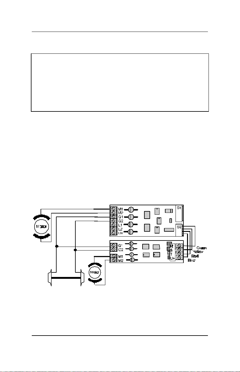
Connecting the slave motor driver
On the slave motor driver there is a 4-outlet row of terminals (U+,
T, S, R) and two 2-outlet terminals (M1, M2 and G1, G2).
The 4-outlet terminals are intended for wiring to locomotive
decoder LE200/230. The illustrations show the connection of
LP200 to LE230.
First install locomotive decoder LE200/230, using its instructions.
Connecting the slave motor driver to locomotive decoder
LE230
DIGITAL plus
Page 4

4 LP200 Slave Motor Driver
Then wire terminals U+, T, S, R of slave motor driver LP200 with
the corresponding terminals on locomotive decoder LE200/230.
Then connect terminals G1 and G2 of the slave motor driver with
the corresponding terminals on locomotive decoder LE200.
Now connect the first motor to terminals M1 and M2 of the
locomotive decoder, then connect the second motor to terminals
M1 and M2 of slave motor driver LP200.
You must not connect the motor output M1 and M2 of the slave
motor driver in parallel with motor outputs M1 and M2 of the
locomotive decoder! This will cause the failure of both units.
Test for correct connections, while programming the locomotive
decoder.
When connecting the motors, make sure that the motors turn in
the correct direction on command "forward move." If that is not the
case, you must reverse the motor leads on the slave motor driver
LP200.
Hüttenbergstraße 29
35398 Gießen, Germany
Hotline: 06403 900 133
Fax: 06403 5332
http://www.lenz.com
This equipment complies with Part 15 of FCC Rules. Operation is subject to the
following two conditions: (1) this device may not cause harmful interference,
and (2) this device must accept any interference received, including
interference that may cause undesired operation.
© 1997 Lenz GmbH, All Rights Reserved
Lenz Agency of North America
PO Box 143
Chelmsford, MA 01824
ph/fax: 978 250 1494
 Loading...