


LH100 Dispatcher’s Throttle |
1 |
Designed for use on all XpressNet systems
LH100 Keypad based Dispatcher's Throttle
Version 3.0 art. no. 21100 December 2002

LH100 Dispatcher’s Throttle |
2 |
Welcome!
Congratulations for purchasing the held controller LH100. We wish you this model train control system.
Digital plus by Lenz® hand much enjoyment with using
The LH100 hand held controller is the universal data input device in the Digital plus by Lenz ® system. With it you can:
-operate your locomotives
-assemble, operate, and disassemble locomotives operated as double headers
-use smart-consisting to assemble, operate, and disassemble multi-unit consists.
-throw turnouts and set signals or activate uncoupling tracks
-read out system configurations and redefine them
-read out information from feedback encoders and feedback capable accessory decoders
-program locomotive and accessory decoders as well as feedback devices
This operation manual is intended to make using the LH100 easy for you. To get started, first read the section “First Steps". After you have understood the basic locomotive control, you can familiarize yourself with the full range of functions of this hand held controller step by step and put them to use.
If you should have any questions that are still unanswered after you work your way through this information, then we will be glad to help you further. You can contact us in the following ways:
|
Europe |
North America |
Postal |
Lenz Elektronik GmbH |
Lenz Agency |
address: |
Huettenbergstrasse 29 |
PO Box 143 |
|
D-35398 Giessen |
Chelmsford, MA 01824 |
Phone |
++49 (0) 6403 900 133 |
++1 978 250 1494 |
|
|
|
Fax |
++49 (0) 6403 900 155 |
++1 978 455 LENZ |
|
|
|
info@digital-plus.de |
support@lenz.com |
|
|
|
|
Do you have everything?
Please check if everything is included in the box: Hand held controller LH100
Operation manual (this booklet)
If an item is missing, please contact your retailer to have the missing item replaced.
2
SET-01 Information |
3 |
1 Important information — Please read first!
Your LH100 hand held |
controller |
is a component of the |
Digital plus by Lenz ® system |
and was |
subjected to intense testing |
before shipping. Lenz Elektronik GmbH guarantees problem free operation when you follow these directions:
Depending on which command station (and which software version) you operate your LH100 on, certain functions are not or are only partially available. This manual contains all the possible LH100 capabilities present when used with an LZ100 V3. If you are using a different command control system, the LH100 capabilities may be reduced by the capabilities provided by that system. For details check out the system manual of the system you desire to use your LH100 on.
The LH100 must only be used with systems that have been branded to support XpressNet or the older X-Bus protocols. A branded system will display the XpressNet logo. Any other use than the one described in this operation manual is not allowed and will lead to voiding of the warranty.
Even when other devices (including ones from other manufacturers) have the same connectors, you may not operate the LH100 with these devices unless they display the XpressNet logo. Other systems may use the same connectors but have different internal wiring that can harm the LH100.
Do not expose the LH100 to moisture or extended direct sunlight.
) If you have problems,
please first check this operation manual to see if you may have missed a direction for use. The table of contents and especially the section “Troubleshooting” will help you here.
1 3 8
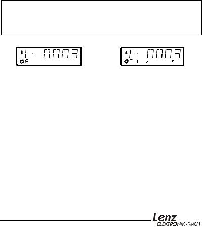
LH100 Configured with |
LH100 Configured with |
German Display |
English Display |
If you need to change the |
display language please refer to |
section “Language Selection” starting on page 64.
LH100 Dispatcher’s Throttle |
4 |
1.1Method for describing commands within this manual:
This manual is written with the assumption that the LH100 is configured for the English language display. You can configure the LH100 for either English or German display. See section 14.2.2 for a description on how to configure the language of your LH100 display.
Showing step-by-step directions:
explanatory text
The entries that you must make using the LH100 keys are shown on the left. In the middle you will see what is shown on the display after the keystroke. To the right a brief explanation is provided.
All the described steps assume that the hand held controller is connected to a Version 3.0 Digital plus by Lenz ® system, and that this system is turned on.
Showing displays and keys in text:
"E 0001" 'Enter'
In most cases the display of LH100 is showed as a picture, as are the keys. If the main text makes reference to displays, then it is put in double quotes. Keys referred to in the text are shown with single quotes.
Cross references:
(Öp. 23)
This arrow points you to a particular page in this operation manual, where you will find additional information about the subject at hand.
Important notes:
) Text marked with this symbol and frame contains especially important information and tips.
4

SET-01 Information |
5 |
2 |
|
Contents |
|
1 |
Important information — Please read first! |
3 |
|
|
1.1 |
Method for describing commands within this manual: |
4 |
2 |
Contents |
5 |
|
3 |
First steps |
7 |
|
|
3.1 |
Connections and starting operation |
7 |
|
3.2 |
Operating Your first Train |
8 |
4 |
Overview of the functions of LH100 |
11 |
|
|
4.1 |
Controlling locomotives |
11 |
|
4.2 |
The function menu of LH100 |
12 |
5 |
The LH100 LCD Display |
15 |
|
6 |
Controlling locomotives with the LH100 |
16 |
|
|
6.1 |
Changing locomotive speed and direction |
16 |
|
6.2 |
Entering a new locomotive address on the LH100 keypad |
16 |
|
6.3 |
Quickly toggling between 2 locomotive addresses |
17 |
|
6.4 |
Selecting an address from the command station stack |
18 |
6.5Taking over control of a locomotive from another hand held
|
|
controller |
19 |
|
6.6 |
Activating locomotive functions |
19 |
|
6.7 |
Showing and changing throttle-notches |
21 |
7 |
Emergency stop and emergency off |
23 |
|
|
7.1 |
Turning off the track power |
23 |
|
7.2 |
Changing operating information during emergency stop/off |
24 |
|
7.3 |
Switching turnouts during emergency stop |
25 |
8 |
Configuring locomotive decoder functions |
25 |
|
9 |
Double header |
27 |
|
|
9.1 |
Prerequisites for creating a double header |
28 |
|
9.2 |
Configuring two locomotives as a double header: |
28 |
9.3Combining locomotives with different speed step numbers into a
|
double header |
30 |
9.4 |
Error messages when assembling a double header |
30 |
9.5 |
Disassembling a double header |
31 |
10 Multi-unit consists (MU) |
32 |
|
10.1 |
What is a multi-unit consist? |
32 |
10.2 |
Prerequisites for a multi-unit consist: |
33 |
10.3 |
Assembling a multi-unit consist (MU) |
33 |
10.4 |
Controlling a multi-unit consist |
35 |
10.5Displaying the members of a MU and switching between
|
locomotives in a MU |
35 |
10.6 |
Removing a locomotive from a MU consist |
36 |
10.7 |
Erasing a completed MU |
37 |
10.8 |
Error messages in multi-unit consists |
37 |

LH100 Dispatcher’s Throttle |
6 |
11 |
Throwing turnouts and setting signals |
38 |
|
|
11.1 |
Feedback and display of the turnout position |
39 |
|
11.2 |
Train operation while controlling turnouts or signals |
40 |
12 |
Displaying feedback |
41 |
|
13 |
Reading/Changing decoder settings |
42 |
|
|
13.1 |
What is programming and what purpose does it serve? |
42 |
|
13.2 |
Programming on the Main - PoM |
46 |
|
13.3 |
Programming on the Programming track |
50 |
|
13.4 |
Error messages during programming |
60 |
14 |
Configuring the LH100 handheld using the SYS menu |
61 |
|
|
14.1 |
SYS_0: entering the XpressNet device address |
61 |
|
14.2 |
SYS_1: the system menu |
62 |
|
14.3 |
SYS_7: Displaying the command station ID |
69 |
|
14.4 |
SYS_8: Displaying the version number of the command station |
69 |
|
14.5 |
SYS_9: Displaying the version number of LH100 |
70 |
15 |
Technical appendix |
70 |
|
|
15.1 |
Compatibility table |
70 |
|
15.2 |
Error messages on the display |
72 |
|
15.3 |
Bits and bytes - Conversion calculation help |
73 |
|
15.4 |
Glossary |
74 |
16 |
Trouble shooting |
75 |
|
17 |
North American Warranty |
77 |
|
6

SET-01 Information |
7 |
3 First steps
In this section you will find out how:
-to connect your LH100 to a LZ100 or a SET02 command station.
-to operate your first train
The following sections below will then explain all the functions of LH100 in detail.
3.1Connections and starting operation
The LH100 can be connected to any XpressNet system including the following components of the Digital plus by Lenz® system:
LZ100; SET02; SET03; Compact
It may also be used with other XpressNet systems including the Atlas Commander and the Roco Lokmaus 2 system.
)As with all XpressNet devices, you can disconnect your
LH100 during operation and reconnect it later when you wish. To make the maximum use of this advantage of XpressNet, install several connector plates LA152/LA153 or install 5 pin din plugs around your layout. You will then always be able to use the LH100 right at the desired place of action.
3.1.1 Connecting to command station LZ100
Insert the 5-pin DIN-connector
-in the 5-pin DIN-jack on the back of your LZ100
or, if you have already installed XpressNet (XBUS) wiring on your layout
-to a connector plate LA150, LA152, or 5 pin DIN plug
3.1.2Connecting to SET02 or Atlas Commander
Insert the 5-pin DIN-connector into a LA152/153 connection plate that is connected to SET02 or Atlas Commander, or to any other XpressNet 5 pin DIN plug.
3.1.3Setting the XpressNet - Address
All input devices connected to XpressNet (XBUS) must have their own unique device address for the information exchange to function correctly. You must therefore make sure that each connected device has its own unique address. Up to 31 devices can be connected to XpressNet, ie. you can program each device
LH100 Dispatcher’s Throttle |
8 |
to addresses 1 through 31. Each hand held controller LH100 has its factory default address set to address 01. If you already have an LH100 at this address or operate another XpressNet device on this address, you must set your new LH100 to another address.
Information on setting the XpressNet address can be found in the section Settings (Öp.61).
3.2Operating Your first Train
For this example we will assume that you are using a locomotive with the address 3.
3.2.1Selecting the locomotive address:
To operate a locomotive you must first enter the address of the locomotive into the LH100:
Press |
On the display you see |
Explanation |
First clear the display, and begin entering the address
The number keyed in is displayed. If you keyed in the wrong number, you can clear the last entered digit with ‘CL’. You do not need to enter leading 0s of an address
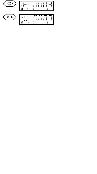
You end the data entry with ‘Enter’. The direction of travel and the status of the functions for this particular locomotive will now be displayed. In this example the direction of travel is forward (arrow on left points up), the functions 0 (light symbol), F1, F3 and F8 are activated.
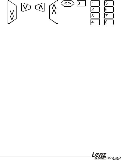
3.2.2Controlling the locomotive's speed:
The speed of travel of the locomotive is controlled with any one of the four following operation keys.
If you press any one of these keys and keep it pressed, the speed steps will automatically be increased (or decreased) until the maximum upper speed limit (or speed step 0) is reached.
8
SET-01 Information |
9 |
Key |
Explanation |
Key |
Explanation |
Each time you press this key, you decrease (or slow down) the speed of the locomotive by 1 step until the locomotive is stopped
Each time you press this key, you decrease (or slow down) the speed of the locomotive by 5 steps in 14 throttle notch mode, 8 steps in 27 or 28 throttle notch modes, or 16 steps in 128 throttle notch mode. The locomotive will slow down at its programmed deceleration rate
Each time you press this key, you increase (or speed up) the speed of the locomotive by 1 step until the maximum speed is reached.
Each time you press this key, you increase (or speed up) the speed of the locomotive by 5 steps in 14 throttle notch mode, 8 steps in 27 or 28 throttle notch modes, or 16 steps in 128 throttle notch mode. The locomotive will speed up at its programmed acceleration rate
Pressing any of these keys will also cause the display to automatically change from showing the locomotive address to showing the locomotives current speed.
Each time you change the locomotive's speed, the display will automatically change from showing the locomotive's address to showing the locomotive's speed and direction. If speed step 0 (locomotive standing still) is reached, the display will automatically change back from showing speed steps to showing the locomotive address.
You can also toggle back and forth between displaying the locomotive's speed and the locomotive's address using the 'Enter' key.
Press |
On the display you see |
Explanation |
If the locomotive address is shown, you can use the ‘Enter’ key to change to showing the speed steps.
This does not change the speed or direction of the locomotive.
1 |
8 |
When showing the locomotive's speed, pressing the ‘enter’ key will again change to showing the locomotive's address.
LH100 Dispatcher’s Throttle |
10 |
3.2.3Changing the locomotive's direction of travel:
To change the locomotives direction of travel, first set the speed to “0”. Then you can change the direction of travel:
Key |
Display |
Explanation |
Each pressing of this key changes the direction of travel of the locomotive. The changed direction will be shown in the display.
When the arrow is up the locomotive goes forward. When the locomotive points down the locomotive will
operate in reverse.
The direction of travel is tied to each locomotive, for example: with a steam engine, forward means “smokestack forward”, regardless of in what direction you have placed this locomotive on the track.
If the locomotive has speed step 00, each pressing of the '<>' key will change the direction of travel.
The '<>' key also has another function: It affects an emergency stop for the specific locomotive contained in the display.
If the locomotive is operating at a speed step greater than 00, pressing the '<>' key once will cause the locomotive being controlled to immediately stop without any pre-programmed deceleration. Only by pressing the '<>' key a second time will change the direction of travel, which is shown in the display by an arrow in the upper right hand of the display that points up (forward) or down (backwards).
3.2.4Emergency stop/Emergency off:
With the  key you cause an emergency stop for the entire layout. When this key is pressed, all locomotives will immediately stop. By pressing this key again, the emergency stop is released. This operation of this key can be configured using the set
command. (Öp. 23)
At this point you have very quickly learned how to operate a locomotive with the LH100 throttle.
There are many more advanced capabilities that the LH100 provides. These features are described in the following sections. It is not important that you know how to use all these advanced features. You can learn to use them at any time in the future when you have a need.
10
SET-01 Information |
11 |
4 Overview of the functions of LH100
This section will provide you:
-a short overview of each of the functions of LH100.
Specific details for using each feature follows in subsequent subsections, which follow this section.
4.1Controlling locomotives
4.1.1Selecting locomotive addresses
There are 3 different ways to select a locomotive address. Up to 9999 addresses for digital locomotives are available to you. With address 0 you control a conventional locomotive in the digital operation. More about entering and selecting locomotive addresses can be found in the section "Entering a new locomotive
address on the LH100 keypad" starting on page (Öp.16 ).
4.1.2Changing speed and direction of travel
You change the speed and the direction of travel of the locomotive with specially shaped keys described in the section "Changing
locomotive speed and direction" starting on page (Öp.16 ).
4.1.3Emergency stop
With the emergency stop you bring one or all locomotives to an immediate stop described in the section "Emergency stop and
emergency off" starting on page (Öp.23 ).
4.1.4Turning locomotive functions on and off
You can access up to 13 functions in each locomotive decoder.
You can also determine if the function operates as a on/off or momentary function. How you control locomotive functions is described in the section "Activating locomotive functions" starting
on page (Öp.19 ).
4.1.5Setting the Throttle-notches for a particular locomotive
With the LH100 you can select 14, 27, 28 or 128 Throttle-notches for the currently selected locomotive address. (Depending on the software version of `the command station you are using). This information is stored in the command station for subsequent use.
How you select the different Throttle-notches and match it to your locomotive decoder is shown in section "Showing and changing
throttle-notches" starting on page (Öp. 21 ).
LH100 Dispatcher’s Throttle |
12 |
4.2The function menu of LH100
The LH100 function menu provides you access to all other functions of the LH100.
The different menu items can be reached in 2 different ways when you are in the locomotive control mode:
Option 1:
Press |
and scroll through |
until you reach the desired |
|
the menus with |
menu |
Option 2 (Quick access):
Press |
and then the number of the desired function. The |
|
corresponding numbers can be found in the detailed |
|
description of each function. |
Following is a brief description of each of the individual LH100 menu items.
4.2.1Setting locomotive decoder functions to on/off or momentary function
Each individual function between F1 and F12 can be configured on a per locomotive basis to either be on/off or momentary. In on/off operation the function is turned on with one keystroke and turned off with the next keystroke. In momentary operation the function is only turned on for as long as you keep the corresponding key pressed. When you release the key again, the corresponding function turns off again.
The procedure for setting this is described in "Configuring locomotive decoder functions" starting on page (Öp.25 ).
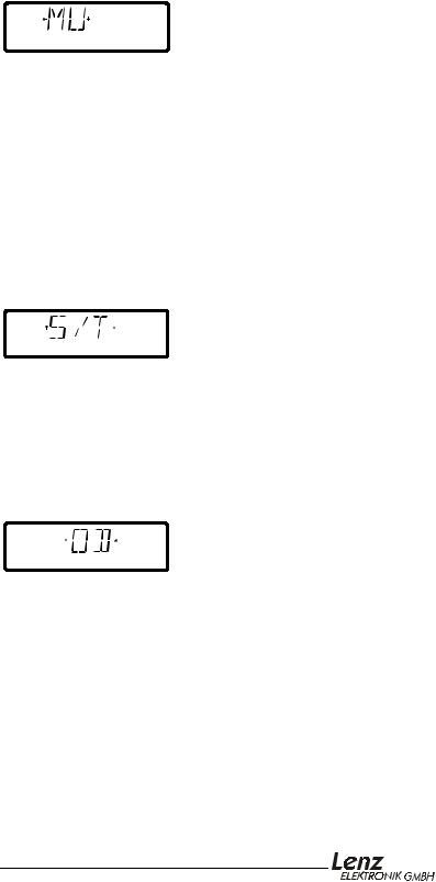
4.2.2Double header
Double heading allows you to easily assign two locomotives to a double header and then operate it as a single locomotive from either locomotive address. The procedure for setting this is
described in "Double herder" starting on page (Öp.27 ).
12
SET-01 Information |
13 |
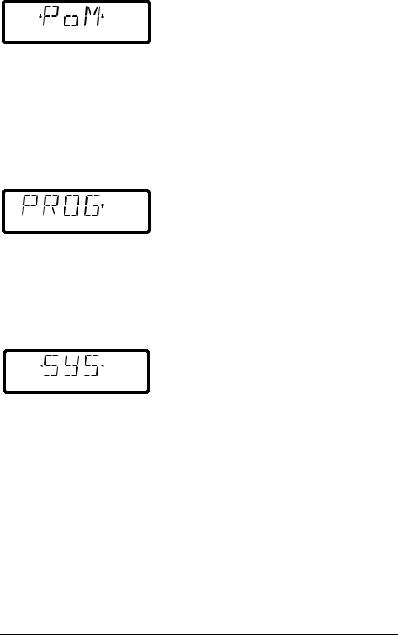
4.2.3Multi-Unit Consist (MU)
The LH100 implements smart consisting. Smart consisting allows you to set up a number of locomotives that can be operated as a single unit. As many as 256 locomotives can be controlled at the same time using a common consist address, which we call the locomotive's multi-unit consist address (MU-address). To you it is as if you only controlled one single locomotive, but all the locomotives in the MU react at the same time.
With the LH100 you can (depending on the software version of the command station you are using) control, assemble and disassemble multi-unit consists.
Detailed information is found in "Multi-unit consists (MU)" starting on page (Öp.32 ).
4.2.4Throwing turnouts and setting signals
Using your LH100 you can throw turnouts, set signals or activate relays. To allow control via the LH100, these devices must be connected to accessory decoders LS100/110/120 of Digital plus by Lenz ® system or other compatible modules. The procedure is controlling these devices using the LH100 is described in "Throwing turnouts and setting signals" starting on
page (Öp.38 ).
4.2.5Display feedback information
The LH100 can also be used to display the status of the inputs generated by feedback encoders LR100/101. These feedback encoders can be used for example to display occupancy of selected locations of your layout.
You find the directions for displaying feedback information in "Displaying feedback" starting on page (Öp.41 ).
LH100 Dispatcher’s Throttle |
14 |
4.2.6Configuring decoder settings: Programming
Each decoder has settings that can be set to customize the decoder to an individual locomotive, for example the locomotive's address, acceleration and deceleration delays are configurable settings on a locomotive decoder. These settings can be changed by a technique we refer to as programming. The LH100 provides two programming methods. Which method you can use depends on your command station and its software version, as well as the locomotive decoders you use.
4.2.7Operations mode programming
Using operations mode programming or "Programming on the main', you can configure the settings of your locomotive decoder while the locomotive is being operated anywhere on the layout. For example, couple your locomotive in front of a heavy freight train and now adjust the acceleration delay to fit the train! Operations mode Programming is descried in "Programming on
the Maim (POM)" starting on page (Öp.46 ).
4.2.8Programming on the programming track
Using a separate programming track you can both configure and read back each of the individual locomotive decoder's settings. Information on programming using a programming track can be found in "Programming on the programming track" on page
(Öp.50 ).
4.2.9System settings
The LH100 allows you to configure several system settings. For example, you can program how the emergency stop button works, check and change the LH100 XpressNet address, read out the software version of your command station, and more. Detailed descriptions can be found in "Configuring the LH100 handheld
using the SYS menu" starting on page (Öp.61 ).
14

SET-01 Information |
15 |
5The LH100 LCD Display
In this section you will learn about the LH100 two-row LCD display.
Depending on which mode of operation you are using, the display will look different. The display for the locomotive address always uses 4 digits. Zeros are added in front of the address if needed.
Here are examples of the most important displays:
A single locomotive with address 0003 is being controlled.
A locomotive with address 1234 is in a multi-unit consist.
A multi-unit consist with address 33 is being controlled.
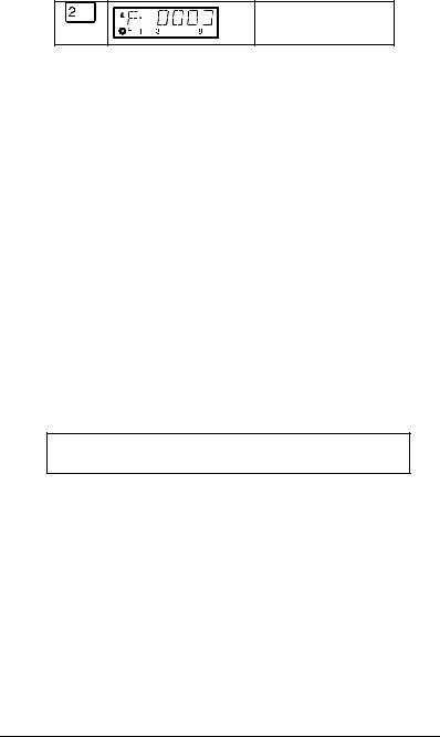
Examples for the display of speed steps:
Speed step 1 in "28 speed steps" mode
1 |
2 |
6 |
8 |
|
|
|
Speed step 28 in "28 speed steps" mode |
|
|
|
Speed step 1 in "128 speed steps" mode |
1 |
2 |
6 |
8 |
|
|
|
Speed step 126 is the maximum speed |
1 |
2 |
6 |
in "128 speed steps" mode |
8 |
LH100 Dispatcher’s Throttle |
16 |
While the speed step is displayed, the locomotive address is hidden. The direction of travel and the functions continue to be displayed.
6 Controlling locomotives with the LH100
In this section you will learn about basic locomotive control using the LH 100. When you want to control a locomotive, you have to call it up first. There are three different ways you can call up a locomotive you want to control:
-Enter the number of the locomotive on the LH100 keypad
-Toggle between 2 locomotive addresses
-Seek out a locomotive from the command station stack.
All addresses from 0 to 9999 are valid. Address 0 is intended for conventional locomotives (ones without a digital decoder).
When you first start using the LH100, it displays locomotive address 0003.
6.1Changing locomotive speed and direction
How to control a locomotive’s speed and direction of travel was already described in the section "First Steps: Controlling locomotives". Please refer back to this section on how to control the speed and direction of your locomotive.
6.2Entering a new locomotive address on the LH100 keypad
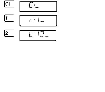
In the following example a locomotive address "1234" is entered using the LH100 keypad.
Press |
On the display you see |
Explanation |
Clear the display first.
Begin to enter the address by pressing the first digit of the locomotive's address on the keypad.
If you make an error, you can use
 to erase the last entered digit.
16

SET-01 Information |
17 |
You continue by pressing each number in the locomotive's address
After you have entered the complete locomotive address you confirm the entry by pressing the 'Enter' key.
The information about functions,
direction and speed step
associated with this address will now be displayed.
If the display flashes after you call up a locomotive address, then the locomotive is already being operated by another hand held controller/ If you desire you can still take over control of this locomotive. More about this in "Taking over control of a locomotive
from another hand held controller" starting on page (Öp.19 ).
6.3Quickly toggling between 2 locomotive addresses
The ‘Esc’ key on the LH100 keypad can be used to toggle between the two locomotive addresses.
Changing the |
Toggle between |
Changing the |
content: |
memory 1 and 2 |
content: |
Memory 1 old address |
|
Memory 2 old address |
Enter new address |
Enter new address |
Memory 1 new address |
Memory 2 new address |
For example: You have just called up locomotive 24. The address for that locomotive is now in one of the two LH100 locomotive memories.
Now press the ‘Esc’ key, and the display will change to the address that is in the second memory. This is for instance address 22. If you now want to operate a locomotive with the address 78, then press ‘Cl’, enter the address 78 and confirm with the ‘Enter’
LH100 Dispatcher’s Throttle |
18 |
key. From now on, you can use the ‘Esc’ key to toggle between address 24 and 78. If you press the ‘Cl’ key, then the locomotive address in the memory currently shown is erased; the locomotive address in the second memory is still available for use.
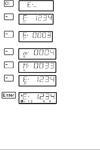
6.4Selecting an address from the command station stack
The command station stack is a database that contains all the locomotive addresses that have been used together with the locomotive's associated data (speed step, function status). With this function you can select an address to control from any of the addresses the database:
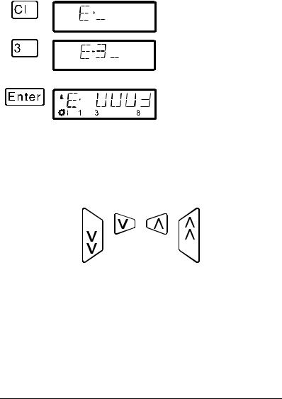
Press |
On the display you see |
Explanation |
First clear the display
The first locomotive from the command station stack is displayed. The “A” in the lower row shows that you are in the selection from the locomotive stack.
Each pressing of the ‘-’ key pages through the locomotive stack in the command station. The two first examples show single locomotive addresses.
This is an example of a locomotive address that is part of a multi-unit consist.
Here is a multi-unit consist address displayed for selection.
Keep paging until you see the locomotive address you want displayed.
Using 'Enter' you can now select the address of the locomotive you want to control. Direction and function status are now displayed.
18
SET-01 Information |
19 |
You can also clear a locomotive from the command station stack, if this option is set in the system settings. For more information see section "SET_5: Erasing locomotive addresses from the
command station stack" starting on page (Öp.66 ).
6.5Taking over control of a locomotive from another hand held controller
When desired you will take over control of a locomotive that is being operated by another engineer. To do this you call up the locomotive's address. The locomotive’s information is now shown flashing. If you don’t want to take over control of the locomotive, but want to find out the current operational data for the locomotive, then each pressing the ‘Enter’ key will update the operational data of the locomotive in your display. If for instance the speed step of the locomotive is changed on the first hand held controller, you can observe that on your hand held controller’s display.
You take over control for this locomotive from the other handheld to your hand held controller by pressing one of the following keys:
The display no longer flashes, and on the display the newest operation and function data is shown. Now the display on the other hand held controller flashes. Only the next operation command (pressing one of the keys shown above) will be sent to the locomotive, which prevents unintended sudden changes of the speed.
6.6Activating locomotive functions
All Digital plus by Lenz ® locomotive decoders have one or more additional functions. The functions are numbered, beginning with 0. Altogether the Digital plus by Lenz ® system can reach up to 13 functions in locomotive decoders.
Functions 0-8 can be activated directly while you are controlling a locomotive (that is the locomotive address or the speed step is displayed), using keys the ‘0’ to ‘8’:
LH100 Dispatcher’s Throttle |
20 |
Press |
On the display you see |
Explanation |
This function 0 is assigned to the headlights in most locomotive decoders and is shown by the lamp symbol in the lower row of the display.
The state of functions 1 to 8 is shown in the second row next to the “F”.
If the functions are set to on/off mode (factory default), then the first key stroke turns on the function.
The next keystroke turns the function off again.
If the function is set to momentary activation, then it is only turned on for as long as the key is pressed. The display shows accordingly.
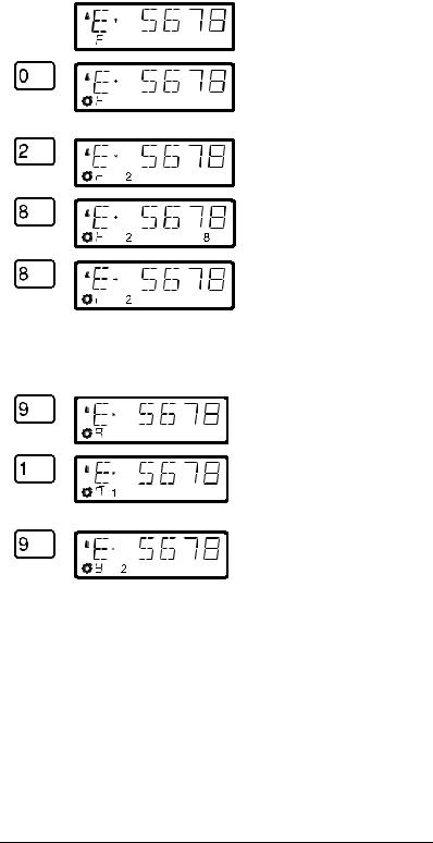
To turn functions 9 to 12 on and off, you must first switch the display over to the high order function block using the '9' key:
The "F" in the lower row changes to a slowly flashing "8".
The '1' key now turns on function 9, the '2' key function 10 and so on. You must simply add the number 8 to the displayed function (flashing display) .
To return to functions 1 to 8, again press the ‘9’ key.
By pressing one of the keys that turn functions on or off, you are also asking the DCC command station to send the locomotive an instruction to activate or turn off that specific function.
20
SET-01 Information |
21 |
6.7Showing and changing throttle-notches
In this section you learn:
-what throttle-notches are
-which throttle-notches are available to you
-how to select different throttle-notches for individual locomotive addresses.
The area from stopped to maximum speed of a locomotive is divided into a series of throttle-notches. The more notches present, the smaller the division between different locomotive speeds. With the LH100 you can set the displayed locomotive address to have 14, 27, 28 or 128 throttle-notches.
This is how you show/change the speed step modes:
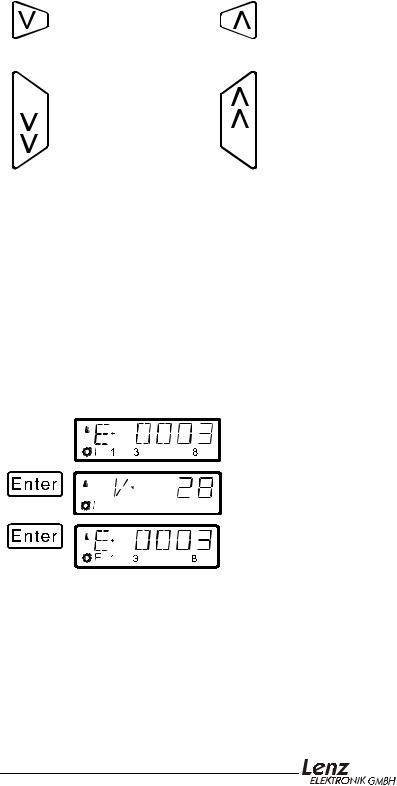
Press |
On the display you see |
Explanation |
Call up the locomotive address whose number of throttle-notches you want to see or change. Make sure that the locomotive is on speed 0; if needed press the '<>' key.
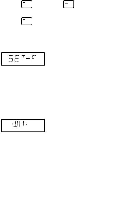
After pressing the ‘+’ key the current number of LH100 throttlenotches is shown. 28 throttlenotches is the default for version 3.0
By repeated pressing of the ‘+’ key you are now shown the possible throttle-notches that are available.
To assign a desired number of throttle-notches to this locomotive address, press ‘Enter’.
)If the locomotive's speed is not 0, then the currently set number of throttle notches is shown as long as you keep the ‘+’ key pressed, but the mode cannot be changed.

LH100 Dispatcher’s Throttle |
22 |
)For locomotive addresses 100-9999, only 28 and 128- throttle-notches are available for use.
)The locomotive decoder's speed step mode (set via CV29) must match the LH100 number of throttle–positions (Öp.42 ).
The following correspondence between system and locomotive decoder must be created:
System |
Locomotive |
|
decoder |
|
|
14 or 27 throttle-positions: |
14 speed steps |
|
|
28 or 128 throttle- |
28 speed steps |
positions: |
|
|
|
Setting the locomotive decoder to a particular speed step mode is done in CV29 of the decoder. For details, see the Digital plus by Lenz ® "Information for locomotive decoders".
You must make sure that the locomotive decoder also “understands” the programmed speed step mode. For Digital plus decoders the following correspondence applies:
DIGITAL plus locomotive |
supported speed step |
decoder types |
modes |
|
|
NMRAXF or XS-series |
14, 27, 28, 128 |
conforming decoders |
|
Other NMRAconforming |
14, 27, 28 |
decoders |
|
all other DIGITAL plus decoders |
14, 27 |
|
|
If unsure, please check in the decoder's operation manual. NMRAconforming Digital plus by Lenz ® decoders can be recognized by the following symbols on the title page of the operation manuals:
22
SET-01 Information |
23 |
7 Emergency stop and emergency off
In this section you will learn about:
-the function of the  key.
key.
-how to turn off track power
-changing information during an emergency stop
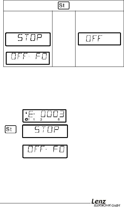
The 'St' key tells the system to perform an emergency stop. You can program this key to have two different effects:
Emergency stop |
|
Emergency off |
the locomotives are |
|
the power on the track is |
stopped, but the track |
OR |
shut off |
power remains on |
|
|
|
|
alternating with |
(flashes) |
The factory default is emergency stop, that is all the locomotives are stopped with track power remaining on. How you program the ‘St’ key is described in section "".
7.1Turning off the track power
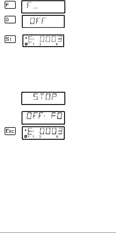
If an emergency stop has been triggered, you can still turn off the power to the track:
Press |
On the display you see |
Explanation |
Call up the locomotive address whose function setting you want to display or change
The emergency stop is displayed.
alternates with
The display “OFF FO” is designed to remind you of the key stroke sequence needed to turn off the track power:
LH100 Dispatcher’s Throttle |
24 |
You start the power off sequence by first pressing the 'F' key.
Next you press the '0' key. The track power is now turned off
(flashes)
Pressing the ‘St’ key a second time resets the emergency stop, the track power is turned on again.
7.2Changing operating information during emergency stop/off
During the emergency stop/emergency off you can change the operating information that will be sent to the locomotives on the layout once you resume operation. This allows you to fix the problem that caused you to emergency stop the layout before you resume operation.
Press |
On the display you see |
Explanation |
The emergency stop or emergency off is displayed
alternates with
You return to controlling
locomotives with ‘Esc’. You can
now change the speed and direction that the displayed locomotive resume with when the layout is turned on again...
You can also call up other locomotives and change their speed and direction. all the changes made will take effect once you resume operation by pressing the 'St' key a second time.
When in this mode the "E" in the display will blink
24
 Loading...