

Page 1
Accessory decoder LS150 1
The DIGITAL plus LS150 turnout decoder provides cost effective turnout control for
up to 6 independent turnouts.
∗ Suitable for twin-coil snap action switch machines
∗ Suitable for motorized switch machines
∗ High current provision to support Peco and Atlas switch machines
∗ The 6 turnout addresses can be sequential or up to 6 user selected
addresses.
∗ Control using separate push-buttons possible.
∗ Configuring the LS150 does not require a separate programming track and the
parameters can be changed at any time in the future even after installation.
LS150
Turnout Decoder for up to 6
independent turnouts
Art. No. 11150
December 2003
Submitted to the NMRA for
C&I testing
Page 2

Accessory decoder LS150 2
Contents
LS150 Turnout Decoder for up to 6 independent turnouts ..................................1
Contents...................................................................................................................2
Important advice, please read first! ..........................................................................3
Use of the LS150 .....................................................................................................3
Technical data..........................................................................................................4
Outputs of the LS150...........................................................................................4
Power and DCC signal Inputs of the LS150 ........................................................6
Connecting the LS150..............................................................................................7
Connection to the AC power supply ....................................................................7
Connection to the NMRA DCC digital system .....................................................8
Connecting twin-coil switch machines .................................................................8
Connecting motorized switch machines ..............................................................9
Connecting a separate push-button to the LS150 .............................................10
Controlling the outputs ...........................................................................................11
Setting the address ................................................................................................12
Setting outputs with sequential addresses ........................................................12
Setting individual addresses and pulse durations of outputs.............................13
Resetting the decoder ............................................................................................14
North American Warranty.......................................................................................16
2
Page 3

Accessory decoder LS150 3
Important advice, please read first!
The LS150 is a component of the Digital plus by Lenz® system
and was submitted to intensive testing before delivery. Lenz
Elektronik GmbH guarantees fault-free operation provided you
follow the advice given below:
Any use other than that described in this operating manual is not
permitted and all guarantees will become void if the LS150 is used
inappropriately.
Connect the LS150 only to devices which are designated for such
connection. This operating manual will inform you which devices
are suitable.
Observe the technical data contained in this operating manual. Do
not in any case exceed the values stated for voltage and power as
this could damage the LS150.
Do not expose the LS150 to damp locations or direct sunlight.
Use of the LS150
The LS150 is a turnout decoder for use in connection with the
Digital plus by Lenz
Turnout decoders are the connecting link between the digital
system and the turnout switch machine. The LS150 can also be
used to drive other layout devices that are driven by coils (for
example switch machines, relays, uncouplers, semaphore signal
drives etc.) on your model railway layout.
The LS150 was designed specifically for the connection of twincoil machines and relays. Here, the AC output of the LS150 is
particularly advantageous for switching twin-coil switch machines
very reliably.
Motorized switch machines can also be connected to the LS150;
this connection requires (depending on the drive used) the use of
an additional 2 simple diodes per turnout.
®
or any other NMRA-DCC compliant system.
Page 4
Accessory decoder LS150 4
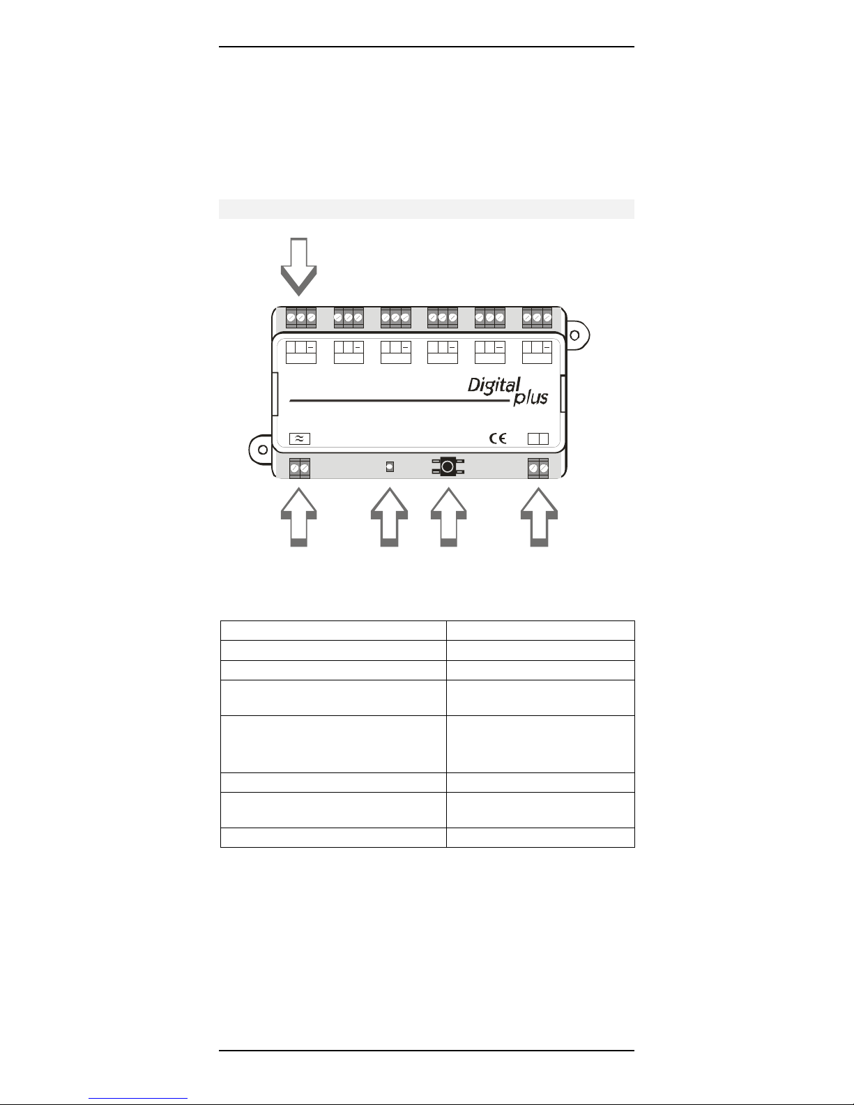
Technical data
6 connections for controlling 6 turnouts
C
+
1
LS150
AC
Transformer
connection
C
+
2
Lenz Elektronik GmbH D 35398 Giessen
+
LED
C
3
C
+
4
Push-
button
C
+
5
by Lenz
+
C
6
JK
Connection to track
outputof th e
digital system
Range of addresses 1 - 1024
Max. voltage on AC input 16 V
Max. voltage on input J, K 24 V
Output voltage approx. 1 V less than
voltage on AC input
Max. power on outputs:
up to 1 sec pulse duration 3 A
more than 1 sec pulse duration 1 A
Pulse duration of outputs settable from 0.1 to 10 sec
Minimum power consumption of
10mA
output
Dimensions 120 x 60 x 20 mm
Outputs of the LS150
The LS150 has 6 outputs, which means that up to 6 devices
(switch machines and/or semaphore signal drives, uncoupling
4
Page 5
Accessory decoder LS150 5
tracks etc.) can be connected to a LS150 and controlled
individually.
Pulse Duration
Having received a turnout command for an output, this output will
be switched on. It will remain so as long as the turnout command
is being sent. Afterwards the output will remain switched on until
the set pulse duration expires.
The pulse duration of the outputs can be set individually from 0.1
seconds to 10 seconds. This makes it possible to adjust the pulse
duration to the needs of the switch machine used. A pulse of 0.1
seconds is adequate for a normal twin-coil snap action switch
machine while a pulse duration of 3-4 seconds is normally needed
for a slow motion switch machine.
Overload protection
The outputs have a joint protection mechanism against overload. If
the permissible maximum power is exceeded, the LS150 will
switch off the terminal ("+" or "-" of an output) which experienced
the short-circuit. You can tell that a blocked status is existent by
the fact that the LED does not shine although a command was
received for this output. The corresponding terminal and all other
outputs still function! The short-circuited terminal can only be
reactivated by switching of the AC power supply.
Voltage on the outputs
AC voltage is applied to the outputs; this is a particularly
advantageous form of voltage for the use of the LS150 with twincoil switch machines and semaphore signal drives as well as
relays.
For technical reasons, the device connected to the
output must have a power consumption of at least
10mA.. This is not a problem with almost all customary
switch machines used for model railroads. If in doubt,
please contact the manufacturer.
Page 6

Accessory decoder LS150 6
Power and DCC signal Inputs of the LS150
The LS150 is supplied with power via the AC input (≈). Use a
suitable transformer – we recommend the Atlas Generator.
Warning: AC voltage must be used to supply power to
the LS150. Do not use a DC supply as this can damage
the LS150.
The power of the transformer used must not exceed
45VA in order to guarantee the proper operation of the
short circuit load protection.
If you desire to use a transformer with a higher
amperage you must protect the LS150s with a 10 ohm
resistor (Radio shack part #271-1101)
The track outputs of a digital system (J,K for
Digital plus by Lenz
®
systems) must not be used to
supply the LS150 with power!
The LS150 receives its commands to activate a turnout from the
NMRA-DCC digital system track outputs connected to the LS150’s
J and K inputs.
6
Page 7
Accessory decoder LS150 7
Connecting the LS150
Twin-coil switch
machine
Coil 1 Coil 2
123
C
C
C
+
+
1
2
LS150
Lenz Elektronik GmbH D 35398 Giessen
+
C
+
3
4
AC transformer
co nne cti o n
Figure 1
Motorized switch
machine
M
C
+
to the track output o f
the digital system
5
by Lenz
C
+
6
K
J
Connection to the AC power supply
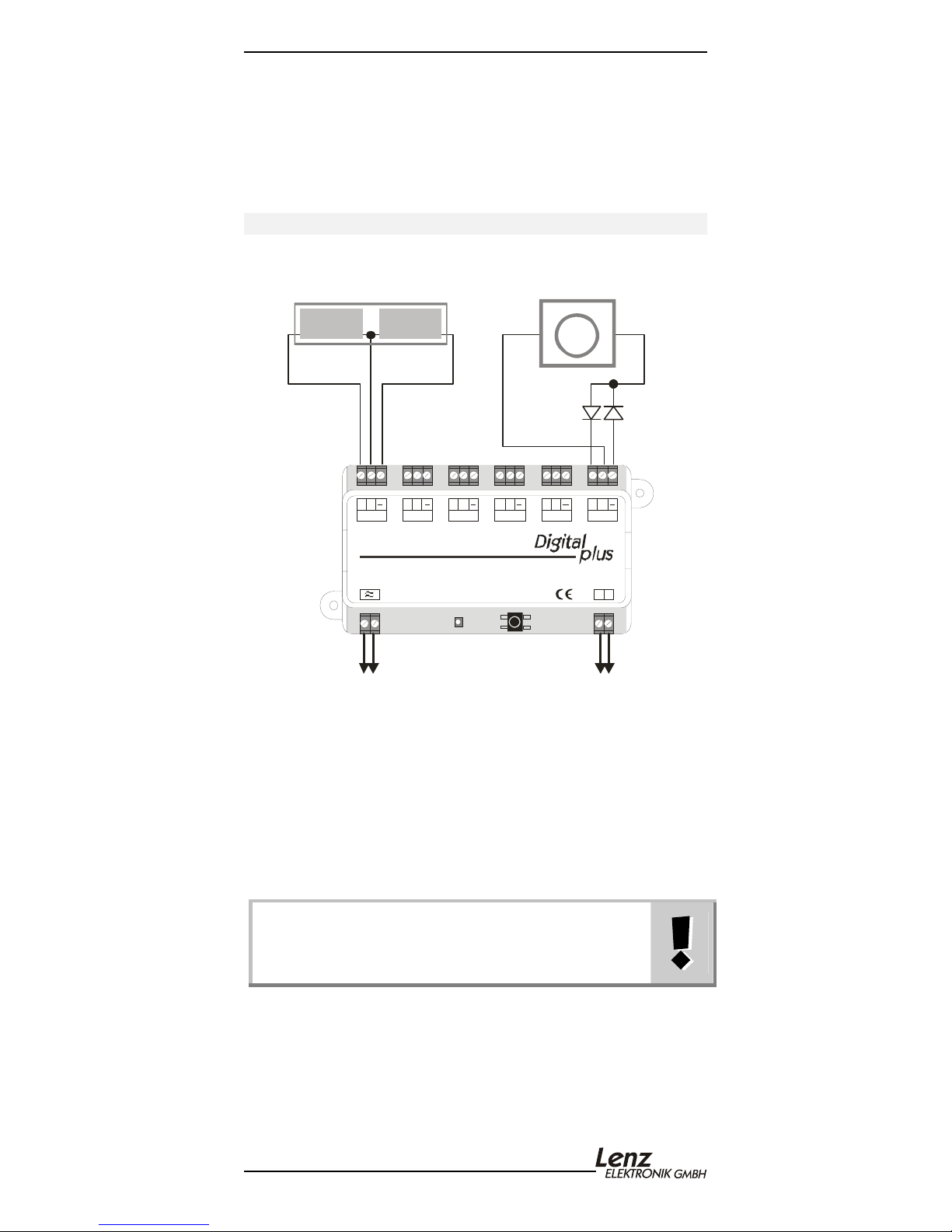
Please see Figure 1 (Page 7), bottom left:
Connect the terminals (≈) to the terminals of an AC transformer.
Observe the maximum permissible voltage (see Technical data).
The power of the transformer must not exceed 45VA in order to
guarantee a functioning load protection. We recommend the use
of the Atlas Generator.
If you desire to use a transformer with a amperage that
is greater then 45VA, you must protect the LS150s with
a 10 ohm resistor current limiting resistor.
(Radio shack part #271-1101).
Page 8
Accessory decoder LS150 8
Connection to the NMRA DCC digital system
Please see Figure 1 (Page 7), bottom right:
Connect the terminals J, K with the track output of the digital
system. In the Digital plus by Lenz
®
system the track output is
also marked with J and K.
Connecting twin-coil switch machines
Please see Figure 1 (Page 7), top left:
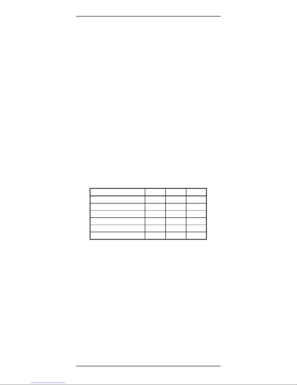
Twin-coil switch machines have three connections. The common
connection of the two coils (2) is connected to terminal 'C'. The
cable of coil 1 (1) is connected to terminal '+'; the cable of coil 2
(3) to terminal '-'.
Depending on the switch machine used, when the output '+' is
activated this results in the switch is set to the ’branch’ or for
“straight”. If the action is opposite to what you desire, simply swap
the connections at the terminals '+' and '-'.
The following table contains common colour coding of some
manufacturers, with reference to the numbering of the cables in
Figure 1. Please use the operating manual of the drive used to
verify whether cable colours have been changed!
Cable no.: 1 2 3
ROCO red black green
Arnold blue grey purple
Fleischmann beige black brown
Trix yellow black green
Märklin blue yellow blue
Viessmann semaphore signal green brown red
When using twin-coil switch machines without auto-shutoff,
extending the pulse duration (see Section "Setting individual
addresses and pulse duration") beyond the factory default setting
is only necessary if the drive does not throw the turnout
completely despite functioning properly. Keep in mind that an
extension of the pulse duration can lead to the switch machine
warming up and is set excessively long, a twin-coil switch machine
can be damaged.
8
Page 9
Accessory decoder LS150 9
Connecting motorized switch machines
Please see Figure 1 (Page 7), top right:
Motorized drives (such as Kato Unitrak, and Circuitron Tortoise)
normally require DC voltage for operation. By reversing this DC
voltage, the direction of rotation of the motor is changed and thus
the turnout is set to a different position.
In order to be able to turnout drives like those described with the
LS150, you need to add 2 simple rectifier diodes. Connect the
switch machine as shown in Figure 1 (Page 7).
The type of diodes you can use depends on the
power consumption of the switch machine.
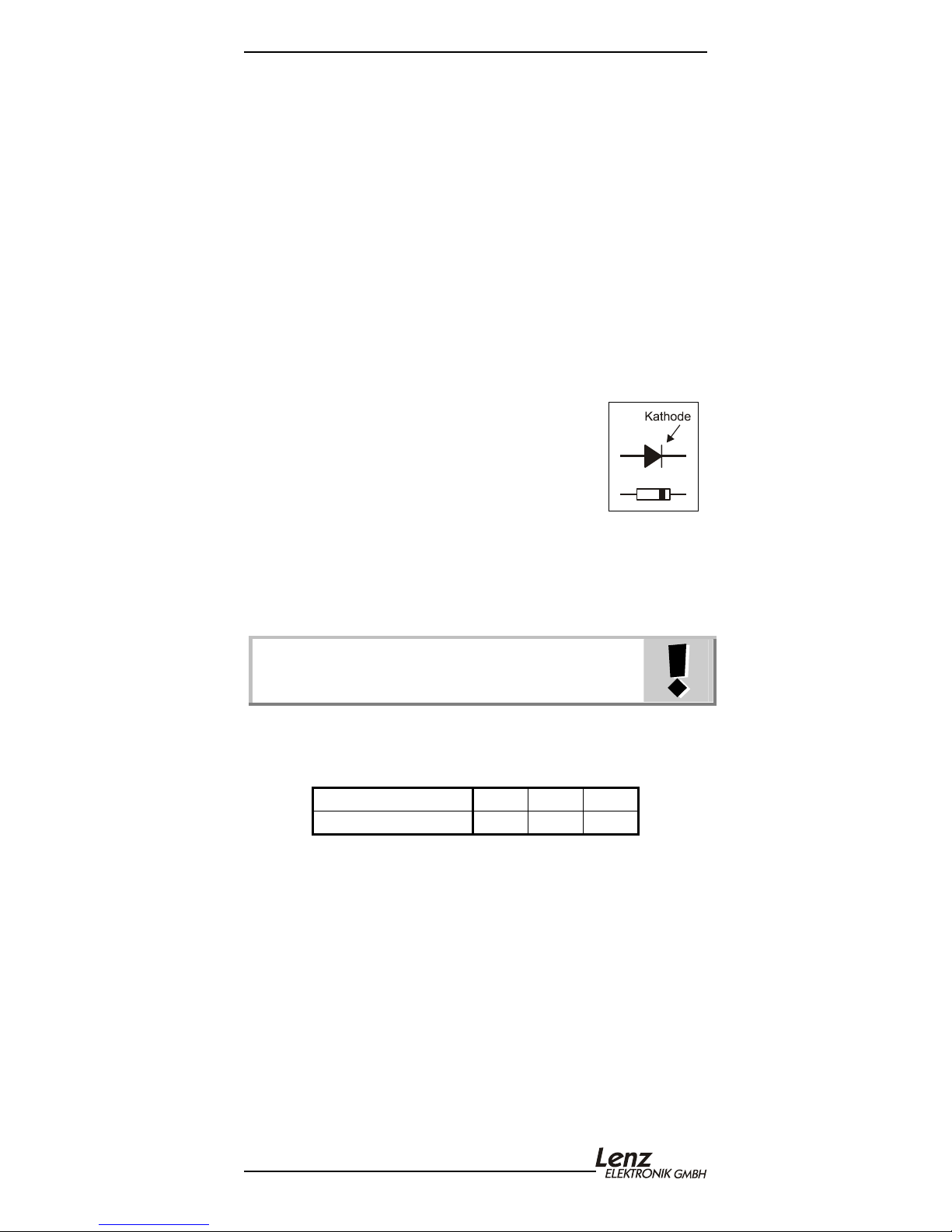
Normally diodes of the type 1N4001 should be
sufficient. (Radio Shack part # 276-1101)
The position of the cathode can be seen by the
ring on the diode.
You may have to extend the pulse duration of the output used for
motorized switch machines to fully move the points to the
respective end position, For more detailed information, please
refer to the Section "Setting individual addresses and pulse
duration".
The use of the LA010 adapter is not required for the
operation of motorized drives. Moreover, this adapter
must not be connected to the LS150!
The motorized point drive from the company Pilz is connected
exactly like a double-coil point drive; no additional diodes are
required:
Connection to LS150: + C -
Cable colours Pilz drive: pink red yellow
Page 10
Accessory decoder LS150 10
Connecting a separate push-button to the LS150
It is possible to control the turnouts connected to the LS150 via
separate push-buttons (or REED contacts). The point or signal
drive used should have auto-shutoff to avoid damage to the switch
machine should the push button be held down for two long a time.
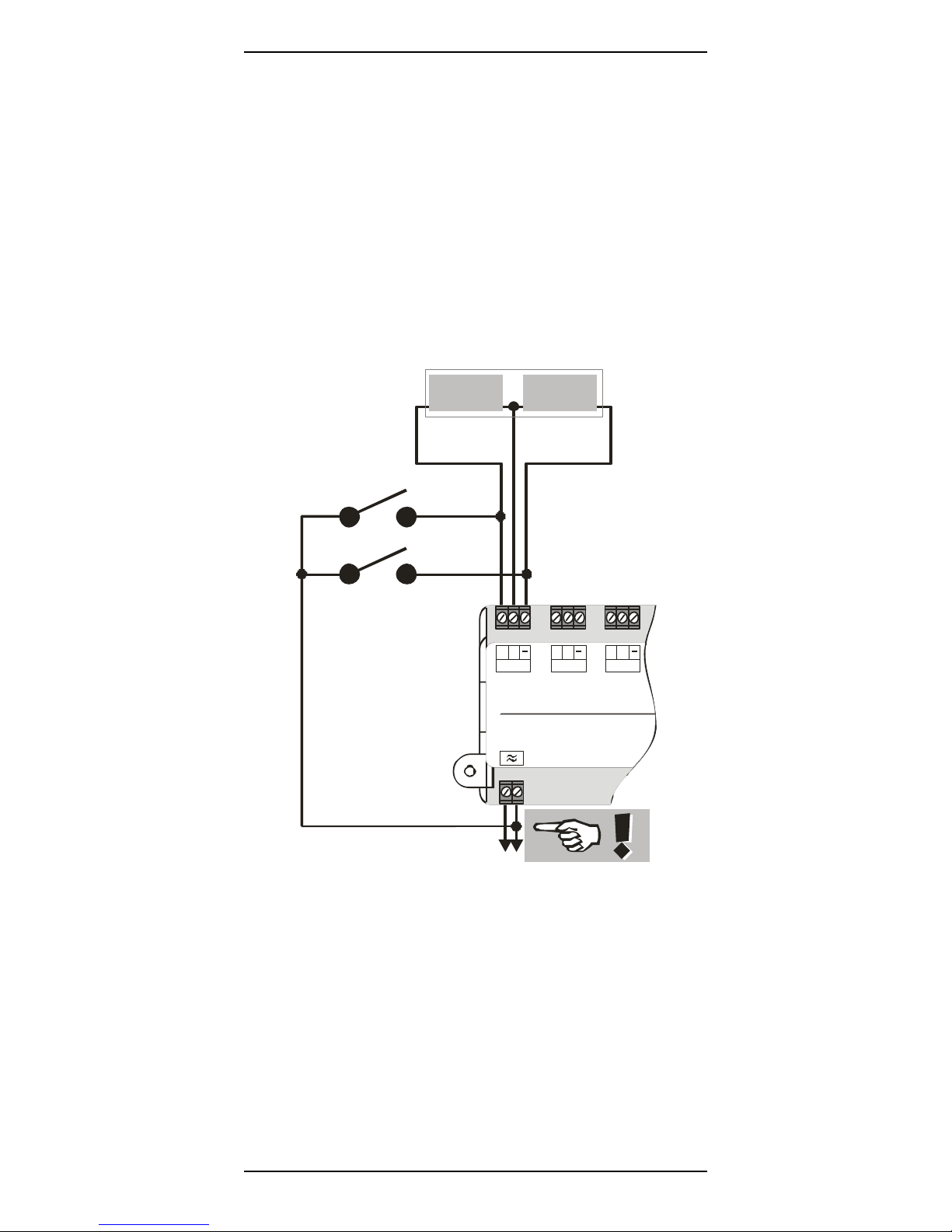
Wire the push-buttons and/or Reed contacts in accordance with
Figure 2:
Twin-coi l
switch
machine
K1
K2
Coil 1 Coil 2
123
C
+
1
LS150
C
+
2
Lenz Elektronik Gmb
C
+
3
The figure shows a typical twin-coil switch machine. The two coils
are connected to the terminals + and - of an output of the LS150.
Two push-buttons K1 and K2 are connected as shown. When
connecting the push-buttons, make sure that the common
connection of the push-buttons is connected to the AC terminal on
10
AC
tr ansf o rme r
connection
Figure 2
Page 11
Accessory decoder LS150 11
the right (marked with in Figure 2) otherwise the turnout will not
function properly!
Press push-button K1 to activate coil 1 and press push-button K2
to activate coil 2. This way you can control the turnout both
digitally with the LS150 or manually with the push-buttons K1 and
K2.
Only use voltage-free contacts for this procedure, e.g.
Reed contacts! The ROCO track 42518 is also suitable.
Note: The C terminals of different LS150s may not be
connected to each another!
Controlling the outputs
The LS150 will only activate one output at a time. Incoming
turnout commands are stored until they can be processed. If the
same LS150 receives several turnout commands in a row, which
cannot be processed simultaneously due to the pulse duration set,
the corresponding outputs are activated in the order received. This
feature is ideal for setting routes.
Page 12

Accessory decoder LS150 12
Setting the address
The LS150 decoder is set at the factory for control of turnout
addresses 1 through 6.
There are two different ways of setting the addresses of the
outputs:
1. Set output 1 to the desired address; the remaining outputs are
automatically set to the 5 following addresses.
2. Set each output to an individual address; the addresses of the
outputs need not be sequential.
In order to be able to set addresses, the LS150 must be
connected to a power supply (AC voltage input ≈) and to the DCC
track signal (inputs J,K). You do not need switch machines
connected to the LS150 to set its addresses. You can also set the
addresses of the LS150 when the installation is completed. This is
helpful if you wish to change addresses later or wish to reuse the
LS150 on a different model railway.
Setting outputs with sequential addresses
Connect the LS150 to both the AC voltage supply and track output
as described in the Section "Connecting the LS150" (Page 7).
Then turnout on your DCC system (such as your
Digital plus by Lenz
®
system.)
1. Choose the turnout address which you wish to set the first
output of the LS150 to.
2. Press the push-button on the LS150 and keep it down until the
LED shines continuously (this will take approx. 3 sec.).
Release the push-button. The LED remains turned on and the
LS150 changes from the normal operating mode into the
setting mode. Output 1 of the LS150 will now assume the
address of the first turnout command it receives.
3. Proceed as if you wanted to activate the switch machine of the
selected turnout address by pressing the necessary keys on
your NMRA DCC system. It does not matter whether you
press the key to switch the turnout for "divergent" or "straight",
e.g. when using the LH100, use the keys '+' or '-'.
4. The point address received with the turnout command is now
allocated to output 1 of the LS150. Outputs 2 to 6 are
automatically set to the following turnout addresses.
You can tell that the setting was effected when the LED turns off
and the turnout command is carried out, i.e. the corresponding
12
Page 13

Accessory decoder LS150 13
switch machine (if connected) is activated. The LS150 now returns
to the normal operating mode.
Setting individual addresses and pulse durations of outputs
Use the following procedure to set individual outputs to unique
addresses. The address of each output does not necessarily have
to be sequential. You can also set a unique pulse duration for
each output.
Connect the LS150 to both the AC voltage supply and track output
as described in the Section "Connecting the LS150" (Page 7).
Then turnout on your Digital plus by Lenz
®
system.
Complete the following steps to set the address and pulse
duration of an output.
1. Press the push-button on the LS150 and keep it down until the
LED shines continuously (this will take approx. 3 sec.).
Release the key. The LED remains turned on.
2. Press the key again for a short moment. The LED starts to
blink:
1 blink, break: output 1 is selected,
2 blinks, break: output 2 is selected etc.
If you only want to set the pulse duration of an output and not
its address, press the key again and proceed with step 4.
3. Select the switch machine address of the digital system to
which you want to set the selected output. Proceed as if you
wanted to activate the turnout and press the corresponding
key of the digital system
1
. The selected output will take this
address as its new address.
4. The LED starts to flash.
5. You can now set the pulse duration of the output. If you do not
want to do this, press the key again for a short moment and
proceed with step 6.
Select a switch machine address between 1 and 100 on the
digital system, depending on the desired pulse duration.
Address 1 stands for 0.1 sec, address 100 for 10 sec.
Proceed as if you wanted to activate the turnout at that
address. The LS150 will use the switch machine address
received as the pulse duration.
6. The LED will start to blink again as described in step 2.
You can now set the address and pulse duration of the
1
For more information about controlling turnouts using your digital system, refer to
the corresponding operating manuals of your NMRA DCC system.
Page 14
Accessory decoder LS150 14
second output. To set this output, go back to step 3.
Repeat this procedure for all outputs of the LS150.
To complete the setting process at any time, press and hold
the push-button until the LED turns off.
If you want to skip a certain setting, simply press the key again
and the LS150 will proceed to the next step. This also makes it
possible to set a single output separately.
If you want to stop the setting procedure at any given time, press
the push-button until the LED turns off.
Note: If the address of an output is reset, the pulse
duration set during a previous setting procedure will
remain unchanged.
Resetting the decoder
To reset the decoder to its factory defaults setting, proceed as
follows:
1. Interrupt the AC voltage supply to the LS150 (You can turn off
the transformer to accomplish this step).
2. Press the push-button on the LS150 and keep it pressed
down.
3. Turn on the AC voltage that is connected to the LS150s ≈
terminals.
4. Proceed as if you wanted to activate a turnout controlled by
the LS150 and press the corresponding key of the digital
system to activate one of the LS150s outputs.
5. Release the push-button.
The LS150 is now reset to the point addresses 1 – 6 and the
shortest pulse duration (100ms). After being reset, the LS150
decoder will complete a test during where each output is activated
one after another. If switch machines are connected to the LS150,
these will be each be activated briefly one after the other.
14
Page 15

Accessory decoder LS150 15
This page has been left blank deliberately
Page 16
Accessory decoder LS150 16
North American Warranty
Lenz GmbH does everything it can do to ensure that its products are free from
defects and will operate for the life of your model railroad equipment. From time to
time even the best engineered products fail either due to a faulty part or from
accidental mistakes in installation. To protect your investment in Digital plus
products, Lenz GmbH offers a very aggressive 10 year Limited Warranty.
This warranty is not valid if the user has altered, intentionally misused the Digital
Plus product, or removed the product's protection, for example the heat shrink from
decoders and other devices. In this case a service charge will be applied for all
repairs or replacements. Should the user desire to alter a Digital Plus Product, they
should contact Lenz GmbH for prior authorization.
Year One: A full repair or replacement will be provided to the original purchaser for
any item that that has failed due to manufacturer defects or failures caused by
accidental user installation problems. Should the item no longer be produced and
the item is not repairable, a similar item will be substituted at the manufacturer’s
discretion. The user must pay for shipping to an authorized Lenz GmbH warranty
center.
Year 2 and 3: A full replacement for any item will be provided that has failed due
to manufacturer defects. If the failure was caused by accidental user installation or
use, a minimal service charge may be imposed. Should the item no longer be
produced and the item is not repairable, a similar item will be substituted at the
manufacturer’s discretion. The user must pay shipping to and from the authorized
Lenz GmbH warranty center during this portion of the warranty period.
Year 4-10: A minimal service charge will be placed on each item that has failed
due to manufacturer defects and/or accidental user installation problems. Should
the item no longer be produced and the item is not repairable, a similar item will be
substituted at the manufacturer’s discretion. The user must pay shipping to and
from the authorized Lenz GmbH warranty center during this portion of the warranty
period.
Please contact your dealer or authorized Lenz GmbH warranty center for specific
instructions and current service charges prior to returning any equipment for repair.
Hüttenbergstraße 29
35398 Gießen, Germany
Hotline: 06403 900 133
Fax: 06403 900155
This equipment complies with Part 15 of FCC Rules. Operation is subject to the
following two conditions: (1) this device may not cause harmful interference, and
(2) this device must accept any interference received, including interference that
may cause undesired operation.
http://www.lenz.com
Lenz Agency of North America
PO Box 143
Chelmsford, MA 01824
ph: 978 250 1494
fax: 978 455 LENZ
[email protected]
Please save this manual for future reference!
Warning: This product contains chemicals known to the state of California to cause
cancer, birth defects or other reproductive harm
© 2003 Lenz GmbH, All Rights Reserved
16
 Loading...