

Page 1

1
B.B.10.0021
Information LH01
Art. no. 21010
2nd version 0515
Page 2

2 Information LH01
Table of contents
1 Welcome! ........................................................................................ 4
2 Important advice, please read first! ................................................ 5
3 Overview of the features of the LH01 ............................................. 6
4 Operating elements of the LH01 ..................................................... 9
5 Connection and initial operation ................................................... 10
6 Emergency shutdown ................................................................... 12
7 Controlling locomotives ................................................................. 13
7.1 Changing the speed step ....................................................... 13
7.2 Changing the direction of travel / Emergency stop ................ 14
8 Selecting locomotives ................................................................... 15
8.1 Selecting a locomotive address from the stack ..................... 15
8.2 Entering a new locomotive address into the stack ................ 16
8.3 Deleting a locomotive address from the stack ....................... 18
9 Locomotive functions .................................................................... 19
9.1 Switching locomotive functions with function keys ................ 19
9.2 Switching locomotive functions with the rotary knob ............. 20
9.3 Assigning locomotive functions to function keys ................... 21
9.4 Setting a locomotive function to permanent or temporary
operation ................................................................................ 22
9.5 Assigning function acronyms to locomotive functions ........... 24
9.6 Deleting a function acronym .................................................. 26
9.7 Changing a function acronym ................................................ 27
9.8 Deleting all function acronyms ............................................... 28
10 Double traction (Double Header) .................................................. 29
10.1 Requirements to assemble a double traction ........................ 29
10.2 Assembling two locomotives in a double traction .................. 29
10.3 Deleting a double traction ...................................................... 31
10.4 Error messages during double tractions ................................ 32
11 Switching points and signals ......................................................... 33
12 Setting (programming) locomotive decoders (PoM) ..................... 34
12.1 Reading CVs via PoM and the address display LRC120 ...... 36
13 System settings ............................................................................. 38
Page 3

3
13.1 Setting and reading a locomotive address on the
programming track ................................................................. 40
13.2 Setting and reading the XpressNet address .......................... 44
13.3 Setting the language .............................................................. 46
13.4 Resetting the LH01 ................................................................ 47
13.5 Resetting command stations (LZV100/LZ100) ...................... 48
13.6 Displaying the version number of the LH01 .......................... 49
13.7 Displaying the version number of the command station ........ 50
13.8 Setting the club mode ............................................................ 51
13.9 Displaying the hardware ID ................................................... 54
13.10 Setting the brightness of the display ...................................... 55
13.11 Enabling/Disabling the displaying of function acronyms ....... 56
14 Technical appendix ....................................................................... 57
14.1 Help in case of malfunction.................................................... 57
14.2 List of error messages ........................................................... 58
14.3 Display text / Languages ....................................................... 59
Page 4

4 Information LH01
1 Welcome!
We would like to congratulate you on your acquisition of the LH01 by
Digital plus by Lenz®. We hope you will enjoy this model railway
control.
The purpose of this operating manual is to explain the use of the
LH01. If you still have questions after reading this manual, please
contact us. We will be happy to help you. There are four different
ways of contacting Lenz Elektronik GmbH:
Mail address:
Lenz Elektronik GmbH
Vogelsang 14
D-35398 Giessen
Phone:
+49 (0) 6403 900 133
A recorded message will
inform you of our
availability.
Fax:
+49 (0) 6403 900 155
E-mail:
If you encounter any problems with the LH01, please contact us,
providing a problem description as well as the following information:
Version number of the command station
Version number of the LH01
Designation, version number and service number of all connected
XpressNet devices (additional manual controls, Interface etc.).
This will help our service department solve the problem. Thank you.
1.1.1 All present?
Please check if all components have been delivered:
- LH01 device
- Connecting cable
- Operating manual (this booklet)
If any component is missing, please ask your specialist supplier for a
subsequent delivery.
Page 5
5
2 Important advice, please read first!
The manual control LH01 is a component of the
Digital plus by Lenz
®
system and was submitted to intensive testing before delivery. Lenz
Elektronik GmbH guarantees fault-free operation if you follow the
advice below:
The LH01 may only be operated with
Digital plus by Lenz
®
system
components. Any use other than that described in this operating
manual is not permitted and all guarantees will be invalid if the LH01
is used inappropriately. Connect your LH01 only to devices that are
designated for such connection. This operating manual will tell you
which devices are suitable. Do not expose the LH01 to damp or direct
sunlight.
WARNING!
Do not leave your model railway system unsupervised
during operation! The heat generated by a shortcircuit creates a fire risk!
Page 6

6 Information LH01
3 Overview of the features of the LH01
Locomotive
addresses
Locomotive addresses range from 1 - 9999.
Address 0 is used to control an analogue
locomotive.
Stack for
locomotive
addresses
The LH01 has a stack for locomotive addresses
that comprises 12 slots. The stack serves to
store the locomotive addresses as well as the
settings used most frequently.
Locomotive
functions and
configuration
Up to 29 functions are available for each
locomotive address.
Use of the LH01 with a command station LZV100
facilitates the independent setting of these 29
functions to permanent or temporary operation.
This setting is stored with the locomotive address
in the LZV100.
Permanent operation:
Press the key once to
enable this function and
again to disable this
function.
Temporary operation:
This function is enabled
as long as the
corresponding key is
pressed, and disabled
as soon as the key is
released.
Function
acronyms
You can assign an acronym to each of the 29
functions from among the list of acronyms
contained in the LH01. This facilitates finding a
desired function. You can enable and disable the
display of acronyms.
Speed steps
The LH01 supports 28 or 128 speed steps
depending on the mode set in the command
station for the respective locomotive address.
The mode cannot be changed.
Club mode
The LH01 has two so-called ‘club modes’ in
which certain functions of the LH01 are disabled.
This allows operation by model railway fans who
are not fully familiar with the LH01.
Double traction
Two locomotives can be joined in a double
traction and controlled simultaneously.
Page 7

7
Multiple traction
Multiple tractions that are already joined (by
means of the LH100 or LH90) can be controlled.
It is not possible to join a multiple traction with the
LH01.
Programming in
operational
mode (PoM)
PoM allows you to change the settings of the
locomotive that is currently being controlled. You
can change, for example, the starting delay,
maximum speed, or sound volume.
Changing a
locomotive
address
You can read or change a locomotive address on
the programming track of the LZV100.
Points, signals
and other
accessories
The address range for points, signals and other
accessories (for example, uncouplers) ranges
from 1 to 999.
XpressNet
Communication with the command station is
made through the XpressNet connection.
As is the case with all other XpressNet devices,
your LH01 can be disconnected and reconnected
during operation. The locomotive controlled last
will continue its operation with the last settings
stored. Once reconnected, this locomotive will
again be controlled.
Housing
Plastic
Dimensions
W 70 mm x H 125 mm x D 38 mm
Page 8
8 Information LH01
Illustrations in the step-by-step instructions:
Key
Display
Explanation
In this booklet all entries in the LH01 are shown on the left.
All corresponding illustrations of the display after entry are
shown on the right.
All operating steps described in this booklet presume that the
LH01 is connected to the Digital plus by Lenz ® system and
that the system is turned on.
Illustration of displays and operating elements:
‘0001’ 'Esc'
The displays and operating elements of the LH01 are depicted
as illustrations. References to the display are indicated by
single quotes (‘’).
Cross references:
(p. 23)
This arrow refers to specific pages of the operating manual
that contain further information on a given subject.
Important information:
Text boxes contain important information or
advice.
Page 9
9
4 Operating elements of the LH01
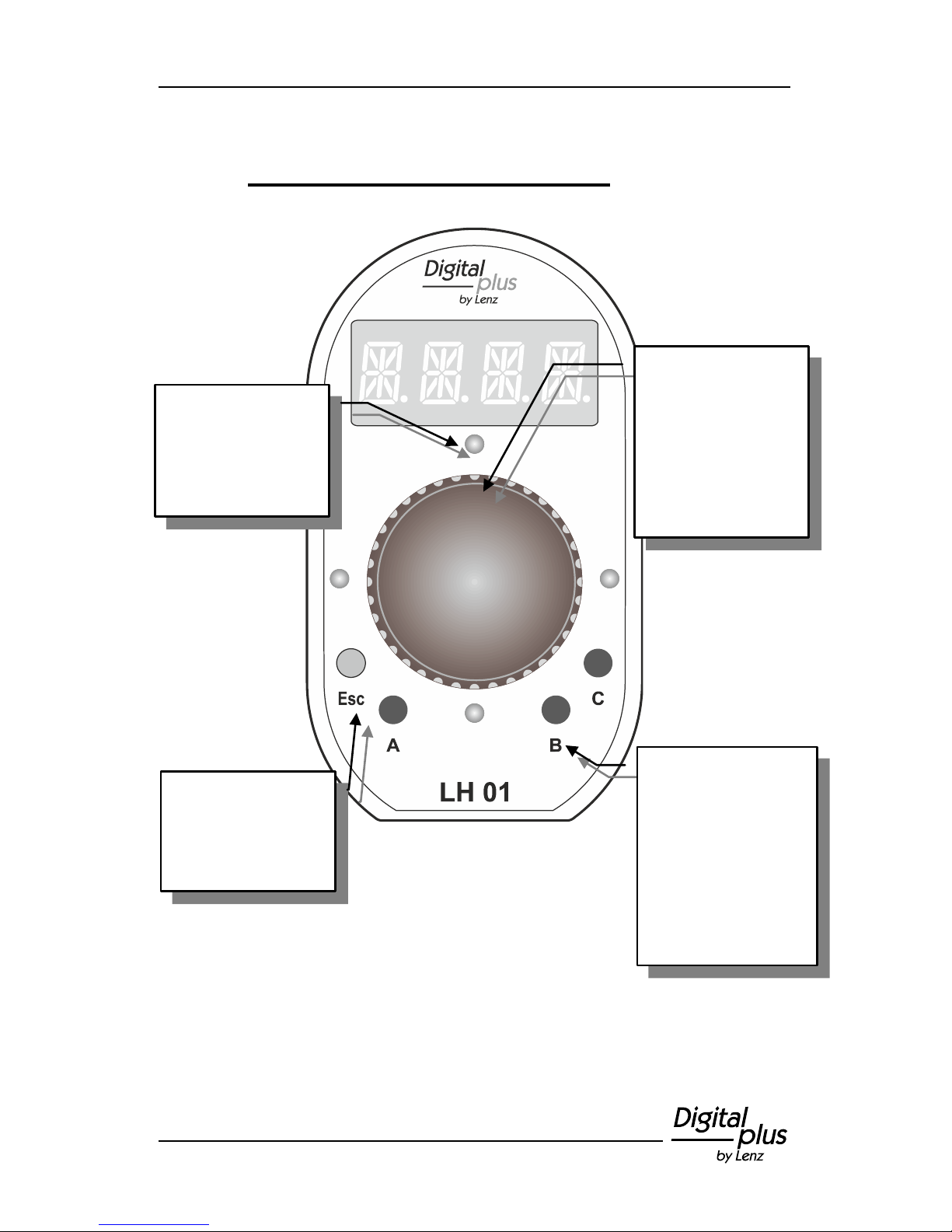
The rotary knob is
used to make
entries. Apart from
the rotary function,
the knob has five
key functions: up,
down, left, right,
and centre.
Function keys
A, B, and C:
For each locomotive
address in the stack,
locomotive functions
(F0 to F28) can be
assigned to these
keys.
Use the ‘Esc’ key to
go back one step in
the menu structure.
The LEDs
surrounding the
rotary knob indicate
when you are in one
of the menus.
Page 10
10 Information LH01
5 Connection and initial operation
The LH01 can be used with the command stations LZ100 or LZV100.
The LH01 requires the software version 3.6 for the
command station LZ100/LZV100.
Update your command station, if necessary.
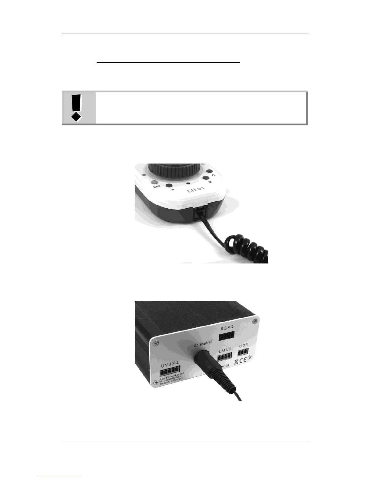
1.
Insert the Western plug of the enclosed connecting cable
into the socket of the LH01.
2.
Insert the five-pole DIN plug into the five-pole DIN socket
at the back of the LZ100/LZV100.
Page 11
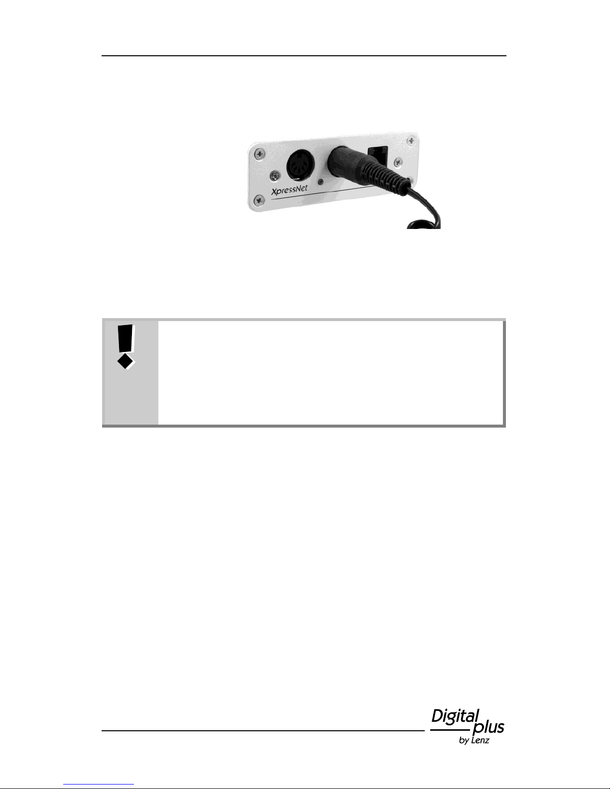
11
or
(if you have already installed an XpressNet connection on
your layout) in an LA152 adapter.
After starting the LH01 the display will show the locomotive address
used last. The factory setting of this address is ‘0003’.
As is the case with all XpressNet devices, the LH01 can
be disconnected and reconnected during operation. After
disconnecting the LH01, the locomotive controlled last will
continue its operation with the last settings stored. Once
reconnected, the locomotive address controlled last will be
displayed, and you will be able to continue controlling this
locomotive elsewhere.
Page 12
12 Information LH01
6 Emergency shutdown
Action
Display
Explanation
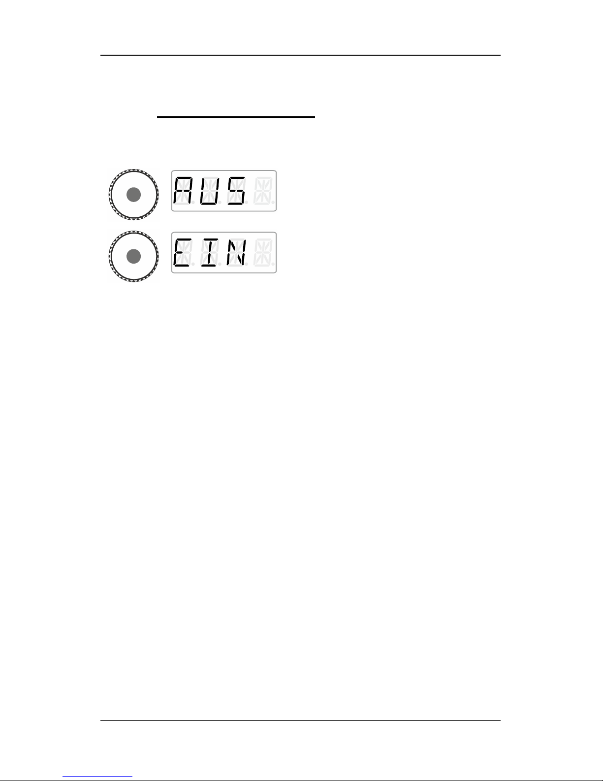
Press the centre of the rotary knob and keep
it pressed until ‘AUS’ is displayed.
The track voltage is switched off.
Press the centre of the rotary knob again until
‘EIN’ is displayed. The track voltage is
switched on again.
During the ‘AUS’ mode, press 'Esc‘ to display the current locomotive
address.
Page 13
13
7 Controlling locomotives
7.1 Changing the speed step
During the first operation, the LH01 uses locomotive address 3 which
is shown in the display.
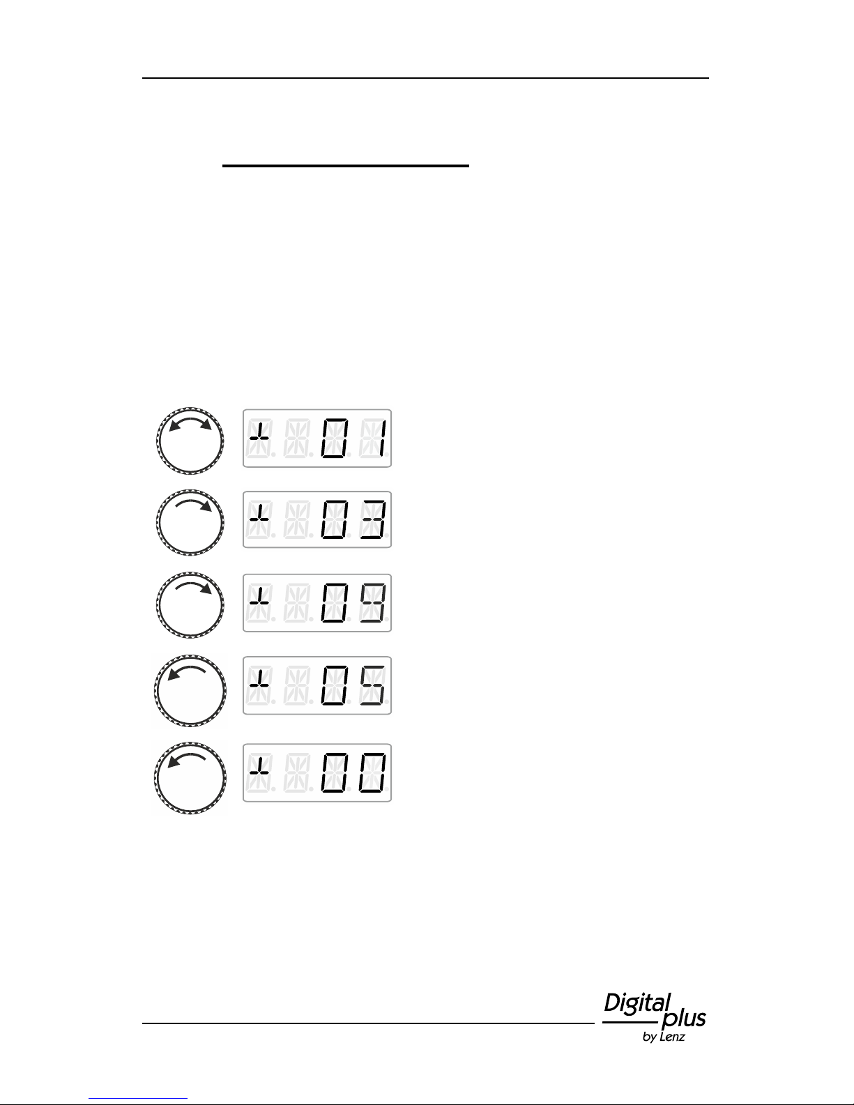
Turn the rotary knob to change the speed step for this locomotive
address:
Action
Display
Explanation
Turn the rotary knob one ‘click’ to the right or
left to display the current speed step of the
locomotive.
A turn clockwise will increase the speed step.
A turn counter clockwise will decrease the
speed step …
… down to a standstill.
Page 14
14 Information LH01
7.2 Changing the direction of travel / Emergency
stop
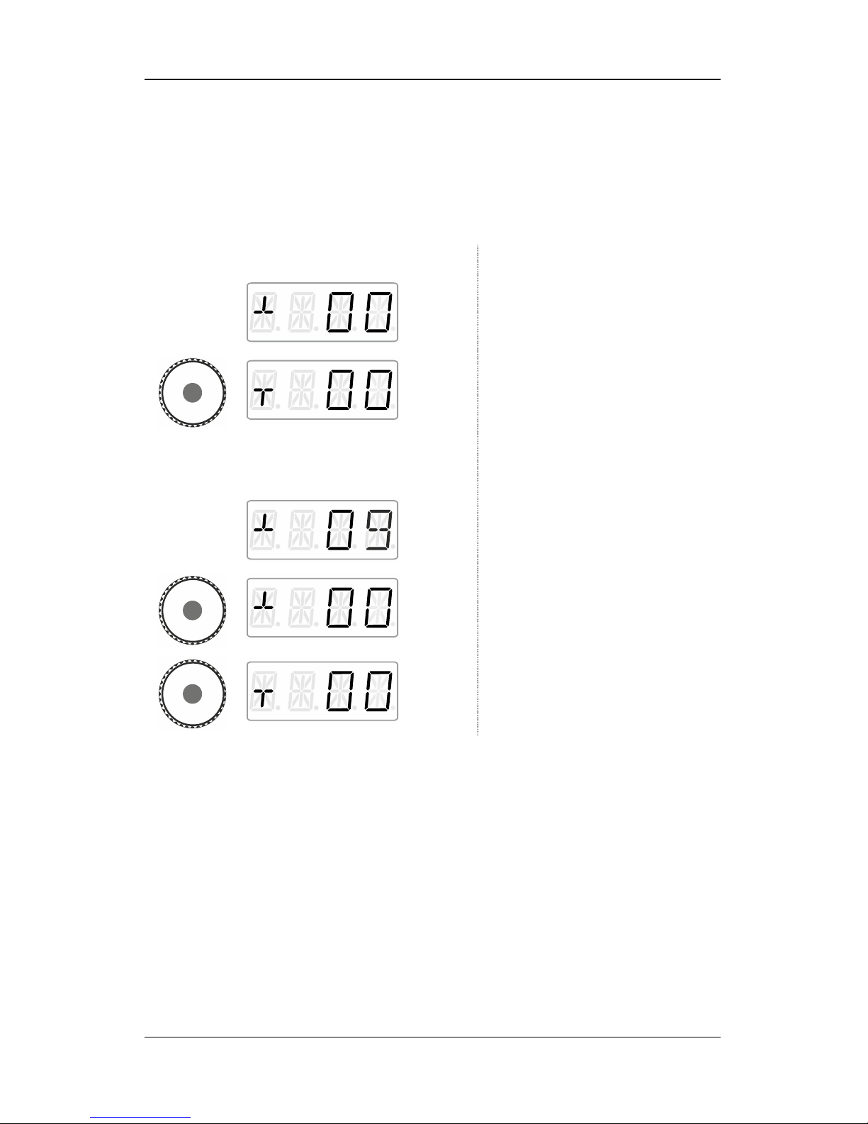
Press the centre of the rotary knob …
at speed step 0
… to change the direction of travel.
at speed step >0
… to trigger a locomotive
dependent emergency stop (the
active locomotive will stop without
the set breaking delay).
Press the centre of the rotary knob
again to change the direction of
travel.
Page 15
15
8 Selecting locomotives
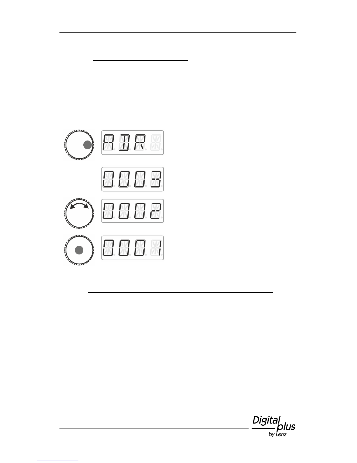
8.1 Selecting a locomotive address from the stack
Ex-factory, three of the twelve stack slots are occupied by locomotive
addresses 1 to 3.
Action
Display
Explanation
Press the right side of the rotary knob until the
LED to the right shines.
Release the rotary knob to display the
locomotive address used last. The factory
setting is address 3.
The locomotive addresses stored in the stack
will be displayed one after the other.
Turn the rotary knob until you reach the
desired locomotive address…
… press the centre of the rotary knob to
select the address.
You are back in the mode ‘Locomotive
control’.
8.1.1 The desired locomotive address is not in the stack?
Re-enter the locomotive into the stack (p. 16). If the stack is full, you
will have to delete another locomotive address from the stack
(p. 18).
Page 16
16 Information LH01
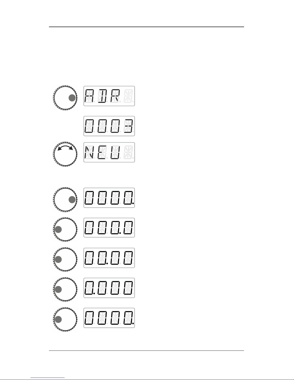
8.2 Entering a new locomotive address into the
stack
Action
Display
Explanation
Press the right side of the rotary knob until the
LED to the right shines.
Release the knob to display the locomotive
address used last. The factory setting is
address 3.
Turn the knob until ‘NEU’ is displayed.
‘NEU’ is not displayed?
This means that all twelve slots of the
stack are occupied by locomotive
addresses. If the stack is full, you will
have to delete another locomotive address
from the stack (p. 18).
Click right. The digit that can be changed with
the rotary knob is marked with a dot.
Click left to change the ‘single’ digit that you
would like to change.
The ‘ten’ digit was selected.
The ‘hundred’ digit was selected.
The ‘thousand’ digit was selected.
The ‘single’ digit was selected again.
Page 17
17
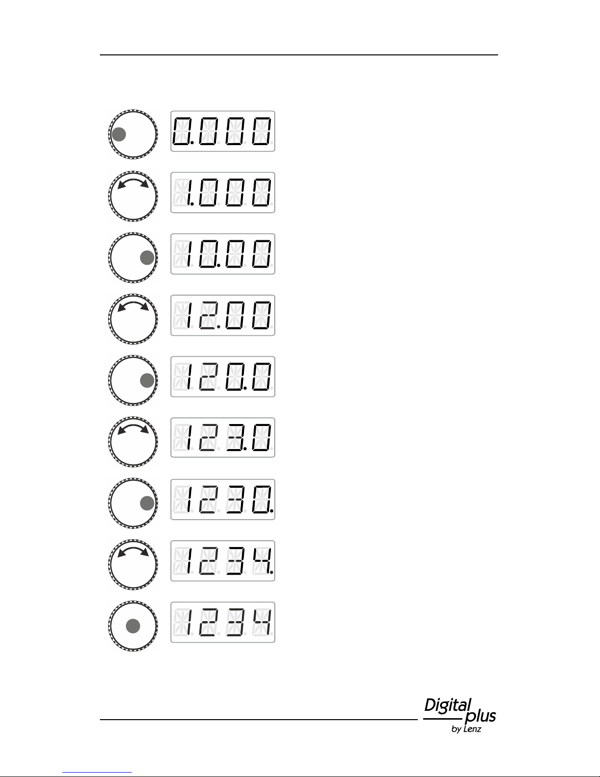
In the following example, locomotive address ‘1234’ is entered:
Click left until the ‘thousand’ digit is marked
with a dot.
Turn the rotary knob until the ‘thousand’ digit
displays ‘1’.
Click right to select the ‘hundred’ digit.
Turn the rotary knob until the ‘hundred’ digit
displays ‘2’.
Click right to select the ‘ten’ digit.
Turn the rotary knob until the ‘ten’ digit
displays ‘3’.
Click right to select the ‘single’ digit.
Turn the rotary knob until the ‘single’ digit
displays ‘4’.
Press the centre of the rotary knob to confirm
your selection.
You are back in the menu ‘Locomotive
control’. You can control the locomotive with
the address ‘1234’ immediately.
Page 18
18 Information LH01
8.2.1.1 ‘NEU’ is not displayed?
This means that all twelve slots of the stack are occupied by locomotive addresses. If
the stack is full, you will have to delete another locomotive address from the stack.
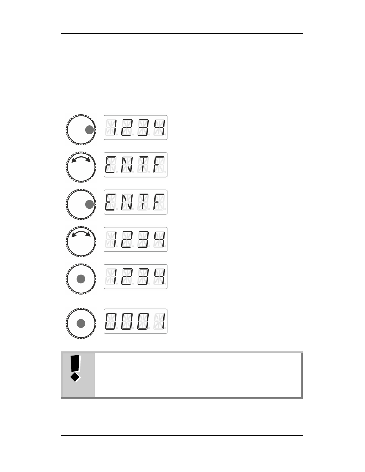
8.3 Deleting a locomotive address from the stack
Action
Display
Explanation
Press the right side of the rotary knob until the
LED to the right shines. Press to display
‘ADR’.
Turn until ‘ENTF’ is displayed.
Click right…
… and turn the rotary knob until the address
that you would like to delete is displayed.
Press the centre of the rotary knob to confirm
your selection.
The locomotive address to be deleted
flashes. Press 'Esc' to cancel the deletion
process.
Press the centre of the rotary knob again to
confirm the deletion. The next locomotive
address from the stack is displayed. You can
control the locomotive immediately.
If you delete a locomotive address from the stack, you will
also delete the assignments of the function keys for this
address.
If you re-enter the locomotive address into the stack, you
will have to re-assign the function keys (p. 24).
Page 19
19
9 Locomotive functions
9.1 Switching locomotive functions with function
keys
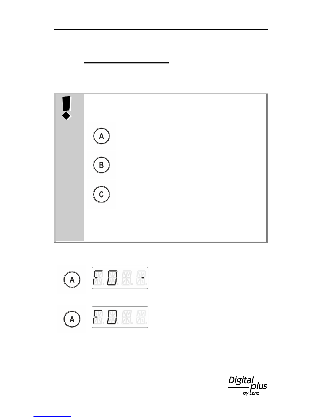
Ex-factory, the function keys are assigned as follows:
switches digital function F0
switches digital function F1
switches digital function F2
You can freely assign the digital functions F0 to F28 to
these function keys. See section Assigning locomotive
functions to function keys (p. 21) for information on how
to proceed.
Action
Display
Explanation
Changes the function status assigned to key
‘A’ for the active locomotive address (factory
setting: F0).
Here: The function is being enabled, as
indicated by the dash on the right.
The function is being disabled.
Function keys B and C behave accordingly.
Page 20
20 Information LH01
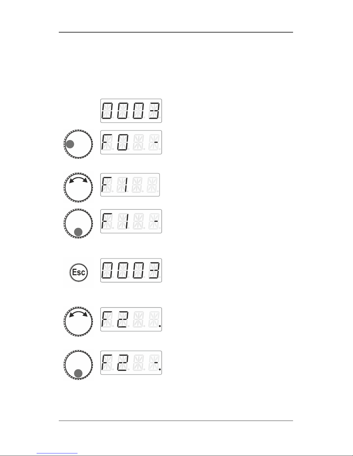
9.2 Switching locomotive functions with the rotary
knob
Action
Display
Explanation
Select the locomotive address for which you
would like to change a function.
Press the left side of the rotary knob until the
LED to the left shines.
The locomotive function selected last is
displayed (here: F0). A dash on the right
indicates that the function is enabled.
Turn the rotary knob to display the function
that you would like to switch (here: F1).
Click the bottom of the rotary knob to change
the function status. Here:
F1 is enabled.
Now, press …
… to leave the menu and return to
‘Locomotive control’
or …
… to select another function and change its
status.
The dot at the bottom right indicates that the
function has been set to temporary
operation.
Enables the function as long as the rotary
knob is pressed.
Release…
Page 21
21
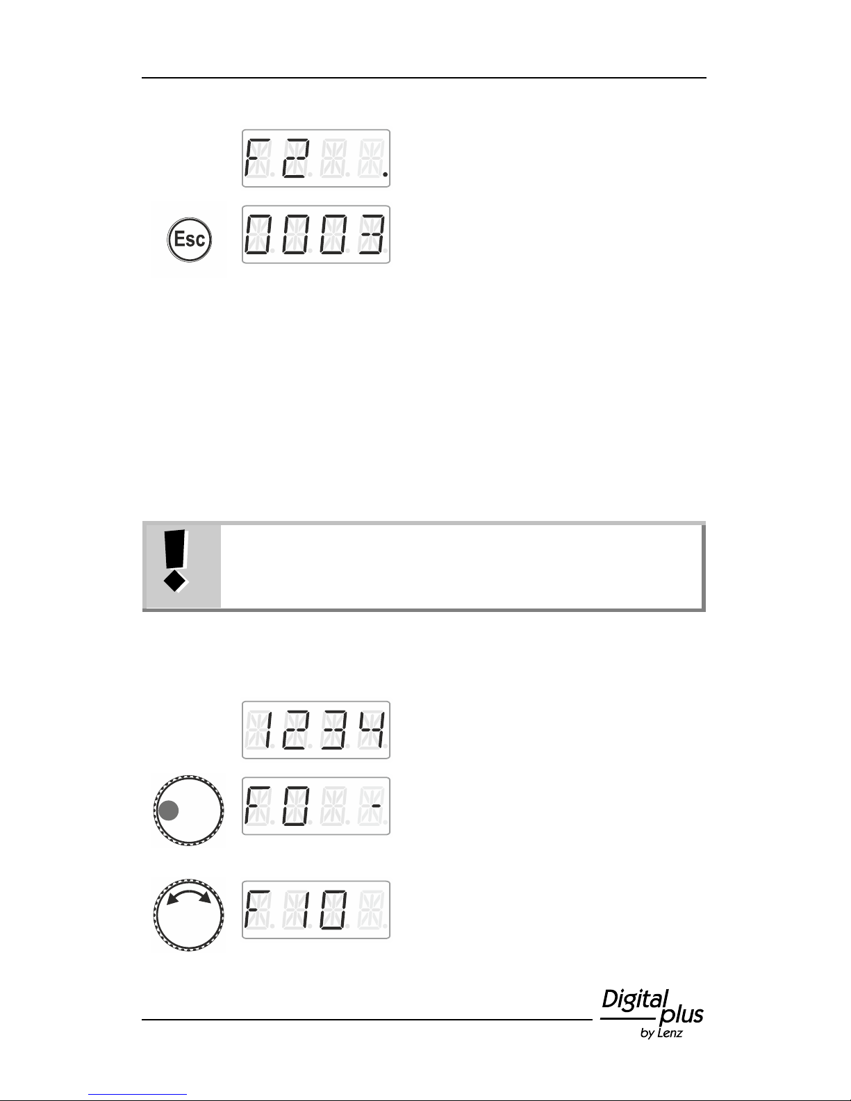
… the rotary knob to disable the function
again.
Press 'Esc' to leave the menu and return to
‘Locomotive control’.
9.3 Assigning locomotive functions to function
keys
Ex-factory, or after re-entering a locomotive address into the stack,
function keys A, B, and C are assigned to functions F0, F1 and F2.
You can also assign other functions to the keys. Functions F0 to F28
are available.
The assignments of function keys are stored separately in
the stack for each locomotive address.
You can select different assignments for locomotive
addresses ‘1234’ and ‘0003’.
Action
Display
Explanation
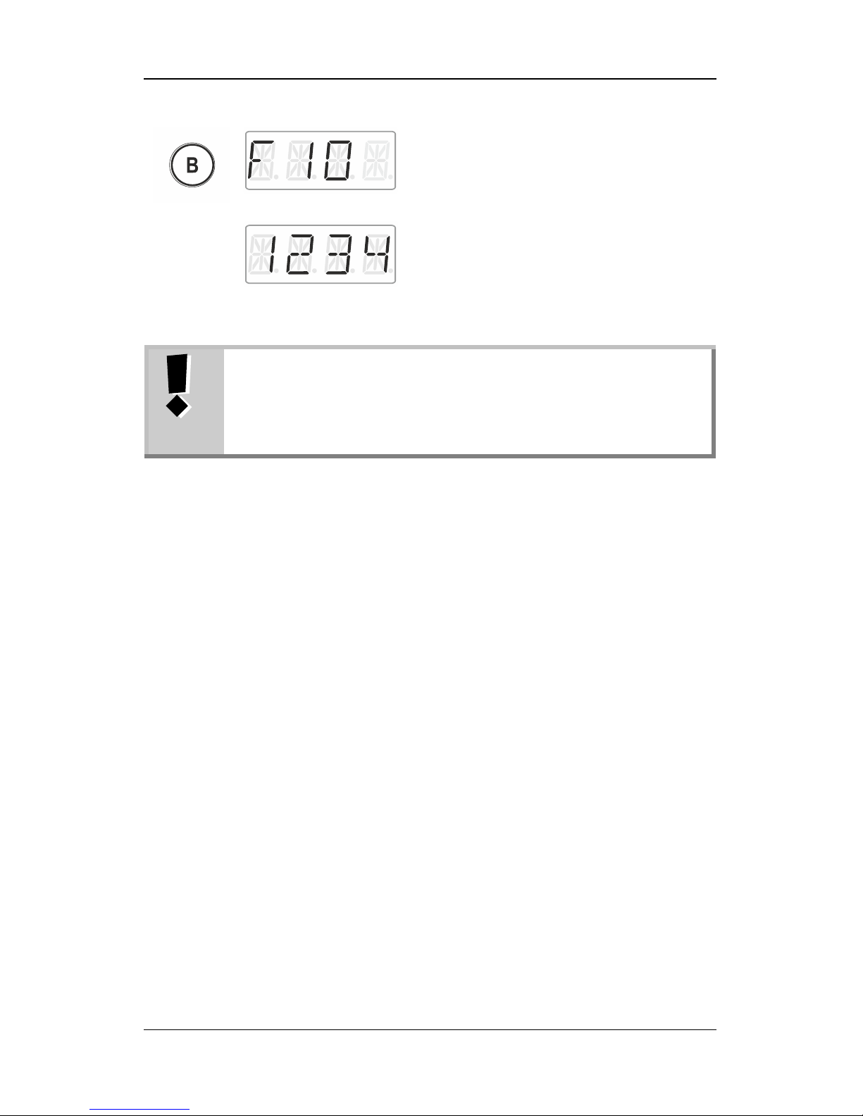
Select the desired locomotive address.
Press the left side of the rotary knob until the
LED to the left shines.
The locomotive function selected last is
displayed (here: F0). A dash on the right
indicates that the function is enabled.
Turn the rotary knob to display the function
that you would like to assign to function key
A, B or C.
Page 22
22 Information LH01
(flashes)
Keep the desired function key pressed until
the display of the locomotive function flashes.
The function has been assigned to this key.
Release the rotary knob to display the
locomotive address. You are back in the
menu ‘Locomotive control’.
If you delete a locomotive address from the stack, you will
also delete the assignments of the function keys for this
address.
If you re-enter the locomotive address into the stack, you
will need to re-assign the function keys (p. 24).
9.4 Setting a locomotive function to permanent or
temporary operation
You can set functions F1 to F28 to permanent or temporary operation.
Permanent operation:
Temporary operation:
Press the key once to enable
the function and twice to disable
the function.
This function is enabled as long
as the corresponding key is
pressed. As soon as the key is
released, the function is
disabled.
Page 23
23
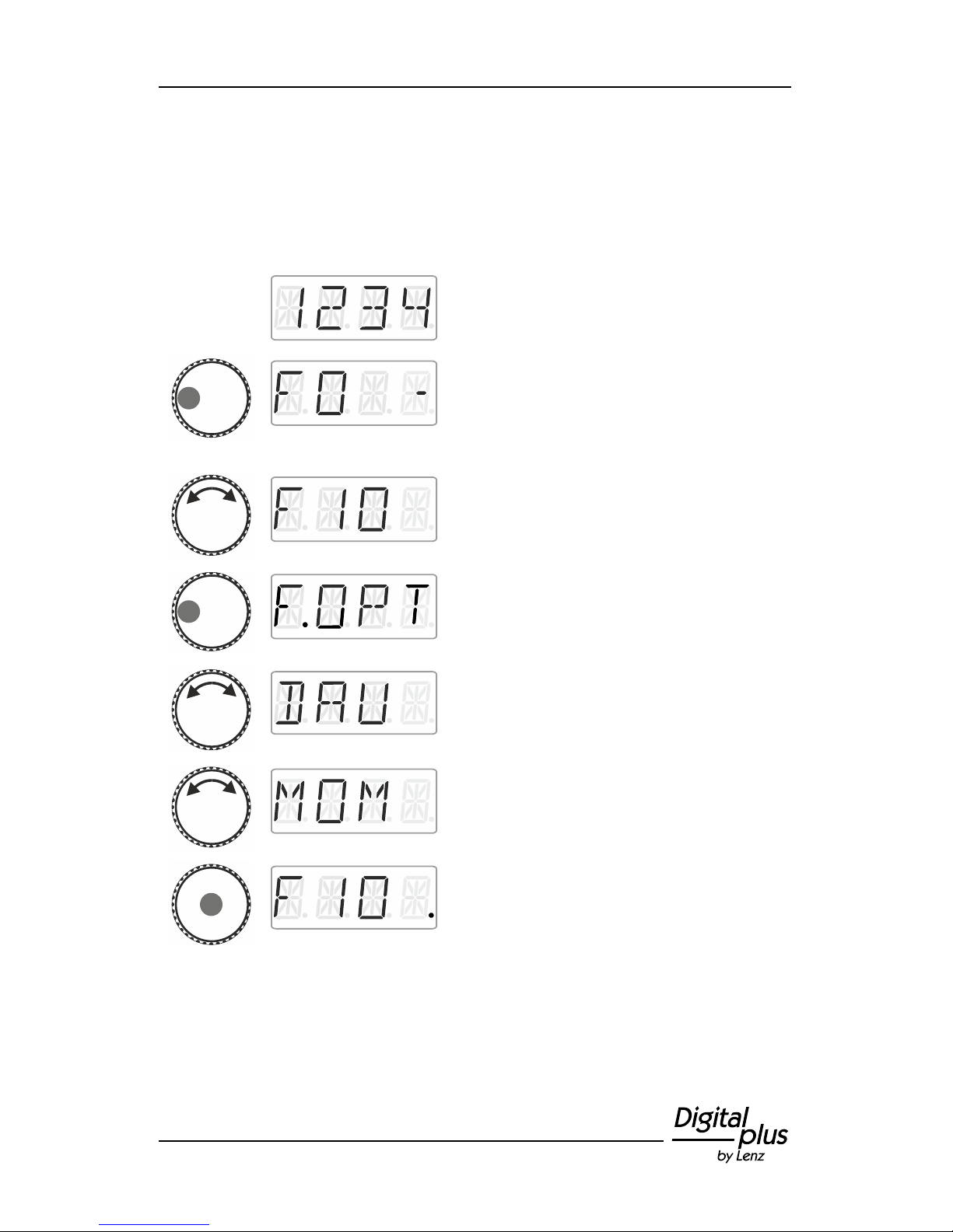
This setting is stored in the command station LZ100/LZV100. When
calling up a locomotive address, the LH01 queries the setting from the
LZ100/LZV100. This setting can be made individually for each
function and locomotive address.
Action
Display
Explanation
Select the desired locomotive address for
which you would like to change a function.
Press the left side of the rotary knob until the
LED to the left shines.
The locomotive function selected last is
displayed. A dash on the right indicates that
the function is enabled.
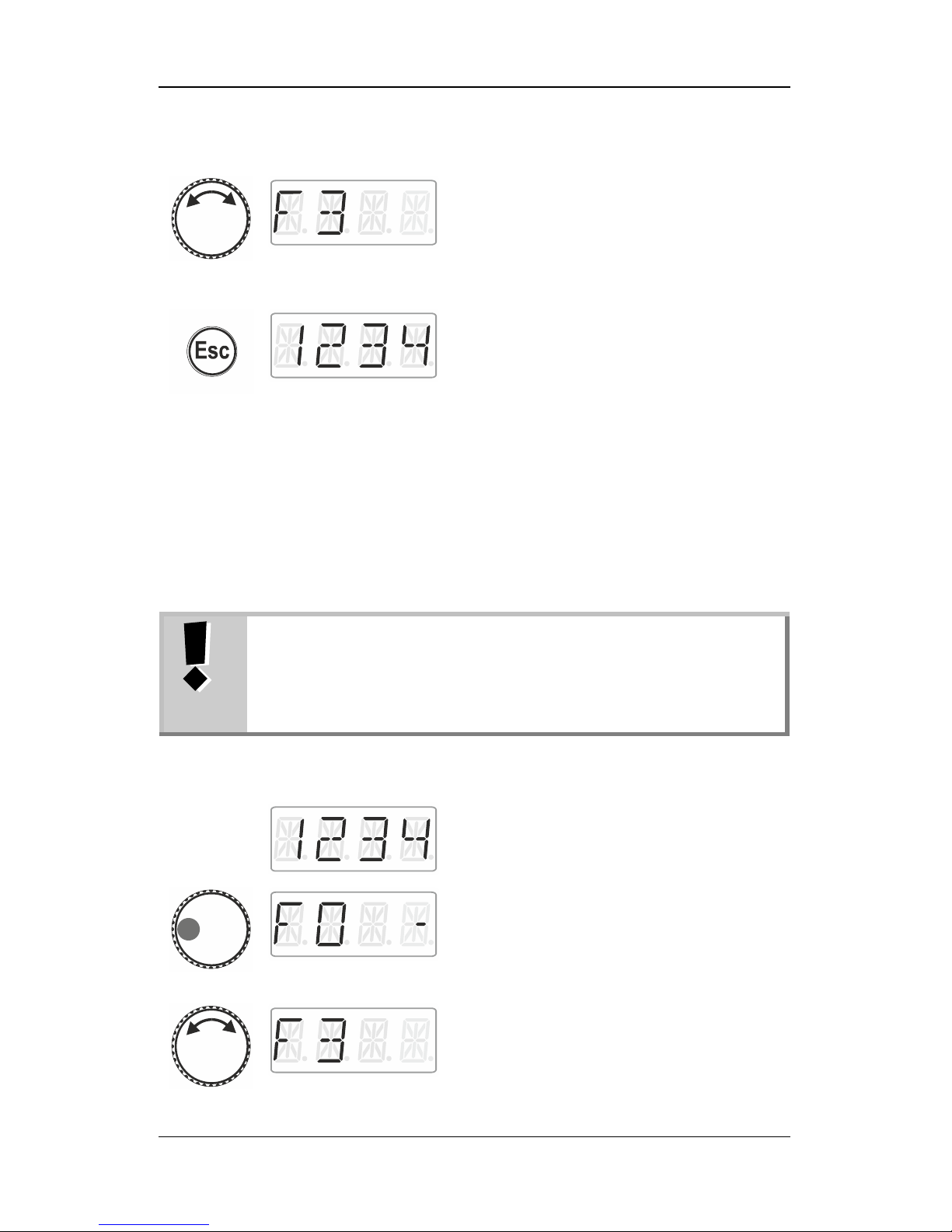
Turn the rotary knob to display the function
that you would like to set to permanent or
temporary operation.
Click left. ‘F.OPT’ is displayed.
Release and …
… click until the desired setting of the
locomotive function is displayed.
Press the centre of the rotary knob to set and
store the setting in the command station.
The dot on the right indicates the setting
‘temporary operation’.
Page 24
24 Information LH01
Either …
select another function for which you would
like to change a setting …
… or …
… press ‘Esc’ to return to ‘Locomotive
control’.
9.5 Assigning function acronyms to locomotive
functions
Always the same question: ‘Which function switches the interior
lighting?’
To make it easier to recall functions, you can assign an acronym to
each function.
The function acronym is stored in the LH01 with the
corresponding locomotive address in the stack. If you are
controlling the same locomotive address with another
LH01, the function acronyms will not be transferred
automatically.
Action
Display
Explanation
Select the desired locomotive address to
assign an acronym to a function.
Press the left side of the rotary knob until the
LED to the left shines.
The locomotive function selected last is
displayed. A dash on the right indicates that
the function is enabled.
Turn the rotary knob to display the function to
which you would like to assign an acronym.
Page 25
25
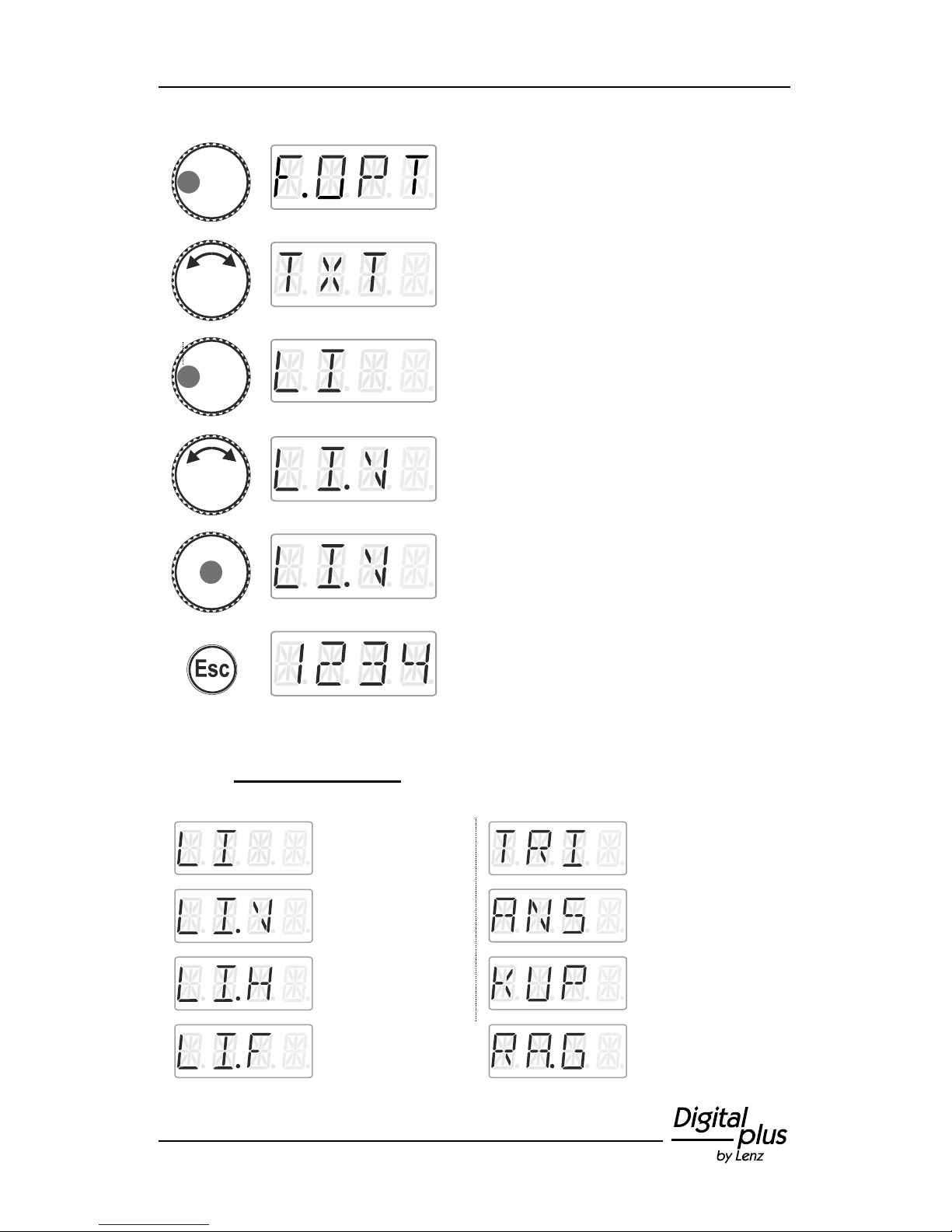
Click left. ‘F.OPT’ is displayed.
Turn the rotary knob to select ‘TXT’.
Click left. The first possible name is
displayed.
Turn the rotary knob to select the desired
name from the list.
Press the centre of the rotary knob to assign
the acronym to the function number.
Press 'Esc' to return to ‘Locomotive control’.
9.5.1 List of acronyms:
General lighting
Thunderer whistle
Lighting front
Announcements
Lighting back
Coupling
Lighting cab
Shunting mode
Page 26
26 Information LH01
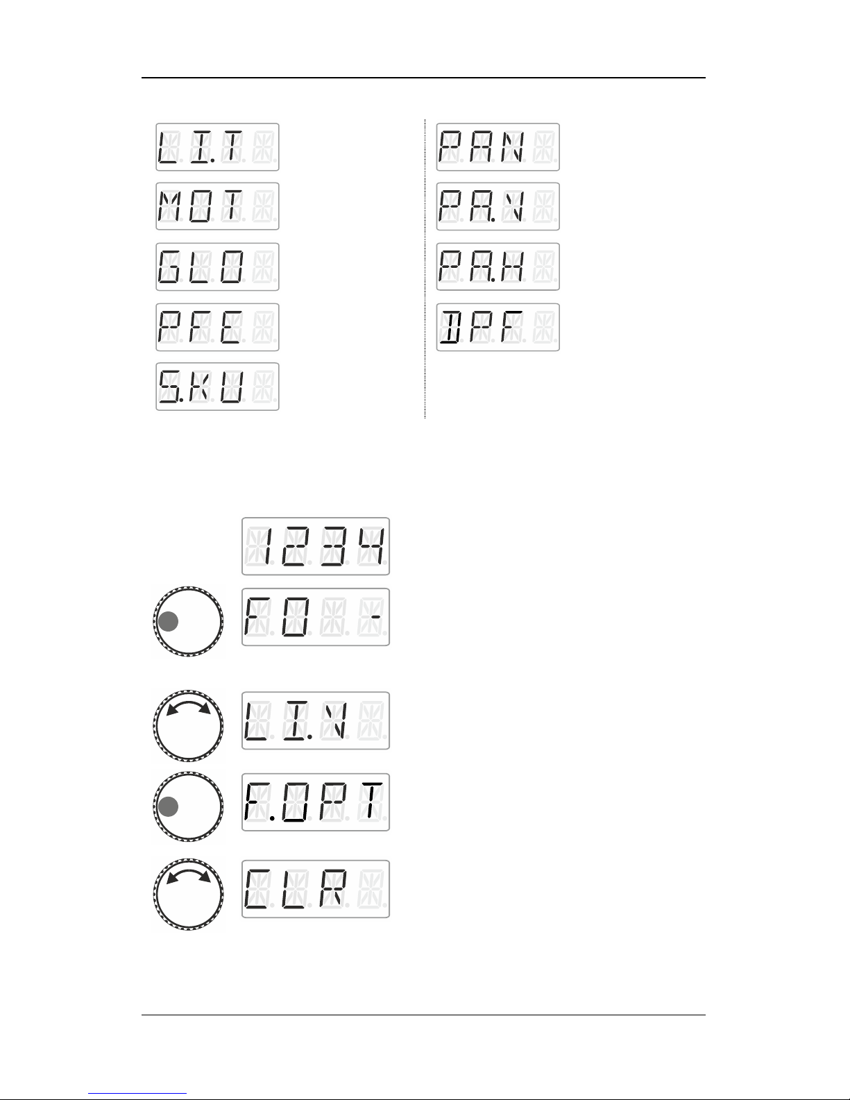
Lighting driving
mechanism
Pantograph
Engine
-front
Bell
-back
Whistle
Steam generator
Coupling sound
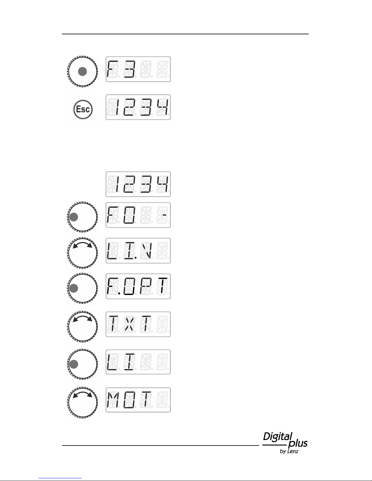
9.6 Deleting a function acronym
Action
Display
Explanation
Select the desired locomotive address for
which you would like to assign an acronym to
a function.
Press the left side of the rotary knob until the
LED to the left shines.
The locomotive function selected last is
displayed. A dash on the right indicates that
the function is enabled.
Turn the rotary knob to display the function
whose acronym you would like to delete.
Click left. ‘F.OPT’ is displayed.
Turn the rotary knob to select ‘CLR’.
Page 27
27
Click the centre of the rotary knob to delete
the assignment. The function number is
displayed again.
Press ‘Esc’ to return to ‘Locomotive control’.
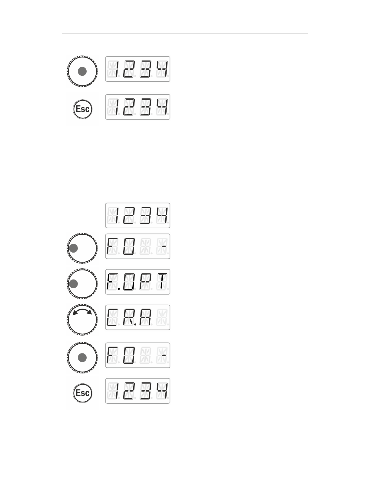
9.7 Changing a function acronym
Action
Display
Explanation
Select the desired locomotive address for
which you would like to change an acronym
for a function.
Press the left side of the rotary knob until the
LED to the left shines.
Turn the rotary knob to display the function
whose acronym you would like to change.
Click left. ‘F.OPT’ is displayed.
Turn the rotary knob to select ‘TXT’.
Click left. The first possible name is
displayed.
Turn the rotary knob to select the desired
name from the list.
Page 28
28 Information LH01
Click the centre of the rotary knob to save the
change to the acronym for the function.
Press ‘Esc’ to return to ‘Locomotive control’.
9.8 Deleting all function acronyms
You can delete all acronyms assigned to a locomotive address in a
single step.
Action
Display
Explanation
Select the desired locomotive address for
which you would like to change an acronym
for a function.
Press the left side of the rotary knob until the
LED to the left shines.
Click left. ‘F.OPT’ is displayed.
Turn the rotary knob to select ‘CR:A’.
Click the centre of the rotary knob to delete all
acronyms.
You are back in the function menu.
Press ‘Esc’ to return to ‘Locomotive control’.
Page 29

29
10 Double traction (Double Header)
With the LH01 it is easy to assemble two locomotives in a double
traction and to control them as if they were one.
10.1 Requirements to assemble a double traction
Before assembling two locomotives in a double traction, you have to
- enter each locomotive address in the stack of the LH01.
- set the speed step of each locomotive to 0 (standstill).
You cannot assemble a conventional locomotive (address 0) in a
double traction! The attempt to do so will result in an error message.
10.2 Assembling two locomotives in a double
traction
Select the first locomotive (here: the locomotive with the address 1)
from the stack and drive it to the location on the layout where you
want to couple it to the second locomotive.
Select the second locomotive from the stack (here: the locomotive
with the address 3) and drive it to the first locomotive.
Ensure that both locomotives are driving into the same direction.
It is possible that the display of one locomotive indicates ‘forward’
while the display of the other locomotive indicates ‘backward’ since
the direction of travel is locomotive-dependent.
Proceed as follows:
Page 30
30 Information LH01
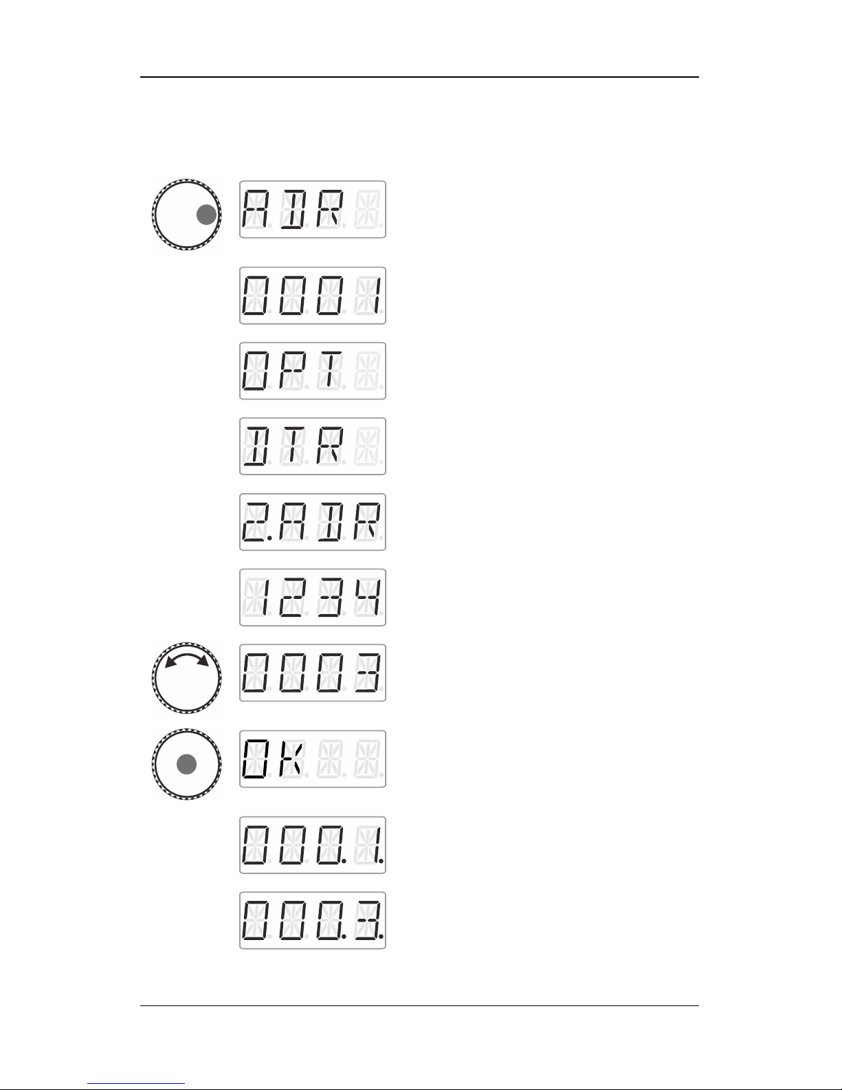
Action
Display
Explanation
Press the left side of the rotary knob until the
LED to the left shines.
Release the knob to display the locomotive
address used last. Here: locomotive address
1.
Click right. ‘F.OPT’ is displayed.
Release the rotary knob to enter the options
menu. The first menu shows the double
traction. If ‘DTR’ is not displayed, turn the
rotary knob until ‘DTR’ is displayed.
Click right. ‘2.ADR’ is displayed.
Release the rotary knob to display the first
address in the stack.
Turn the rotary knob until the address of the
second locomotive that you want to add to the
double traction is displayed.
Press the centre of the rotary knob. ‘OK’ is
displayed.
The addresses of the two locomotives in the
double traction are now marked by two dots
on the right as being part of a double traction.
Page 31
31
You can control the two locomotives assembled in the double traction
as if they were one. Both locomotives will receive control commands
in sequential order.
Both locomotives receive the same control and speed commands.
Commands for switching functions will only be received by the
locomotive that has been selected from the stack.
10.3 Deleting a double traction
To delete a double traction ensure that the speed step of the double
traction is set to 0, i.e. that both locomotives are standing still. Select
one of the two addresses from the stack and proceed as follows:
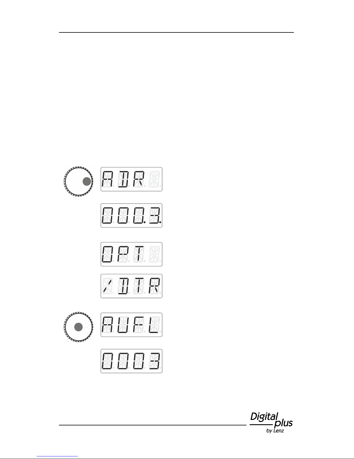
Action
Display
Explanation
Press the right side of the rotary knob until the
LED to the right shines.
Release the rotary knob to display the
locomotive address used last. Here:
locomotive address 3. The two dots at the
bottom right indicate that the locomotive is
part of a double traction.
Click right. ‘F.OPT’ is displayed.
Release the rotary knob to display the
locomotive address used last. The factory
setting is locomotive address 3. Release the
rotary knob to display the option to delete the
double traction.
Press the centre of the rotary knob. ‘AUFL’ is
displayed, followed by …
… the flashing locomotive address. Press
'Esc' to cancel the deletion process.
Page 32

32 Information LH01
Press the centre of the rotary knob again to
delete the double traction.
The locomotives can now be controlled
separately.
10.4 Error messages during double tractions
When assembling a double traction you may receive the following
error messages:
ERR 24:
- The locomotive address was not entered into the stack before
adding the locomotive to the double traction, or
- you tried to add a conventional locomotive (address 0) to a
double traction.
ERR 25:
One of the two locomotives that you would like to add to the double
traction has already been called up by another manual control.
ERR 26:
One of the two locomotives that you would like to add to the double
traction is already part of another double traction.
ERR 27:
The speed step of one of the two locomotives was not set to 0 when
you assembled/deleted the double traction.
Press 'Esc' to return to ‘Locomotive control’.
Page 33
33
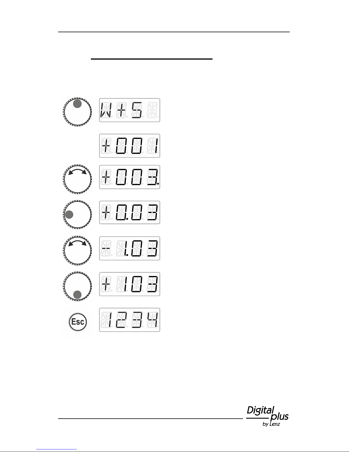
11 Switching points and signals
The LH01 facilitates the switching of points and signals (and other
accessories) in the address range 1 to 999.
Action
Display
Explanation
Press the top of the rotary knob until the LED
at the top shines.
Release the rotary knob to display the point
address used last.
Turn the rotary knob to change the ‘single’
digit of the point address.
Click right or left to select another digit. Your
selection is indicated by a dot next to the digit.
Turn the rotary knob to change the selected
digit of the point address.
Press the bottom of the rotary knob to change
the setting of the point.
Press ‘Esc’ to return to ‘Locomotive control’.
Page 34
34 Information LH01
12 Setting (programming) locomotive decoders
(PoM)
A simple example of a decoder setting that can be changed is the socalled starting delay. The starting delay determines whether
increasing the speed step results in an immediate increase (small
value) or in a gradual increase (high value) of the locomotive’s speed.
‘Programming’ means changing the settings of locomotive decoders.
Settings are stored as numerical values in so-called CVs
(‘Configuration Variables’). Which settings of a locomotive decoder
can be changed is described in the corresponding operating manual.
Further detailed information on settings and CVs of Digital plus
decoders can be found in the ‘Manual locomotive decoders’. You can
download this manual on the following website:
http://www.lenz-elektronik.de/download.php
The LH01 uses ‘Programming in operational mode’ (PoM) to set
decoder settings. The advantage of PoM is that the locomotive may
be located anywhere on the layout rather than be placed on a specific
programming track.
Action
Display
Explanation
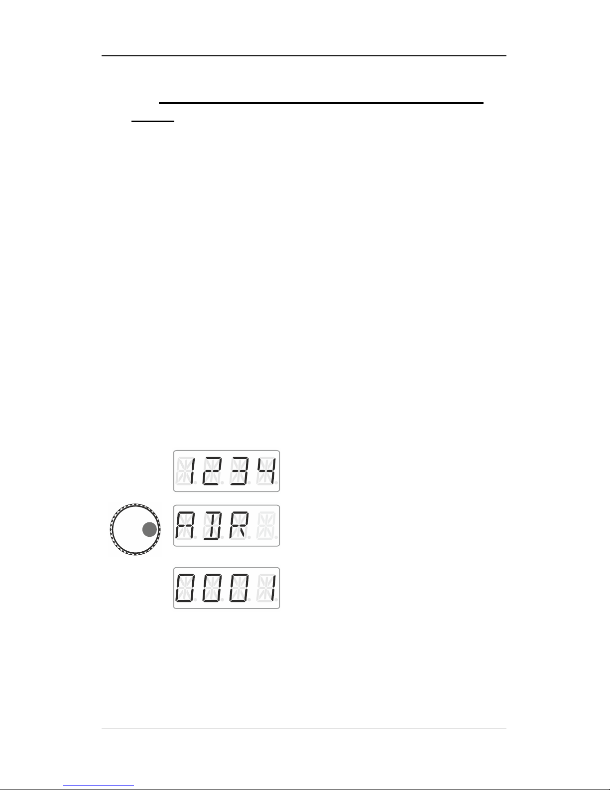
Select the address of the locomotive whose
CVs (settings) you would like to change
(p. 15).
Press the right side of the rotary knob until the
LED to the right shines.
Release the rotary knob to display the
locomotive address used last. Here:
locomotive address 1.
Page 35
35
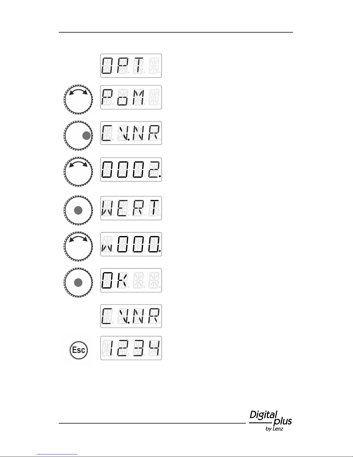
Click right until ‘OPT’ is displayed.
Turn the rotary knob until ‘PoM’ is displayed.
Press right. Now indicate which CV you would
like to change.
Turn the rotary knob and enter the number of
the CV that you would like to change.
Proceed as described under setting a
locomotive address (p. 16). The initial value
suggested is CV2.
Click the centre of the rotary knob to enter the
value.
Turn the rotary knob and enter the value that
you would like to enter into the CV. Proceed
as described under setting a locomotive
address (p. 16).
Confirm the value by pressing the centre of
the rotary knob. This will launch the entering
process.
You can now select and change another CV
or …
… press 'Esc' to return to ‘Locomotive
control’.
Page 36
36 Information LH01
12.1 Reading CVs via PoM and the address display
LRC120
It is possible to read CV values via PoM during operation.
Requirements:
A RailCom-able locomotive decoder
The locomotive is located in a track section monitored by the
address display LRC120.
RailCom transmission is enabled in the decoder.
Information on how to connect the address display LRC120 as well as
the settings of RailCom-able locomotive decoders can be found in the
corresponding operating manuals.
Action
Display
Explanation
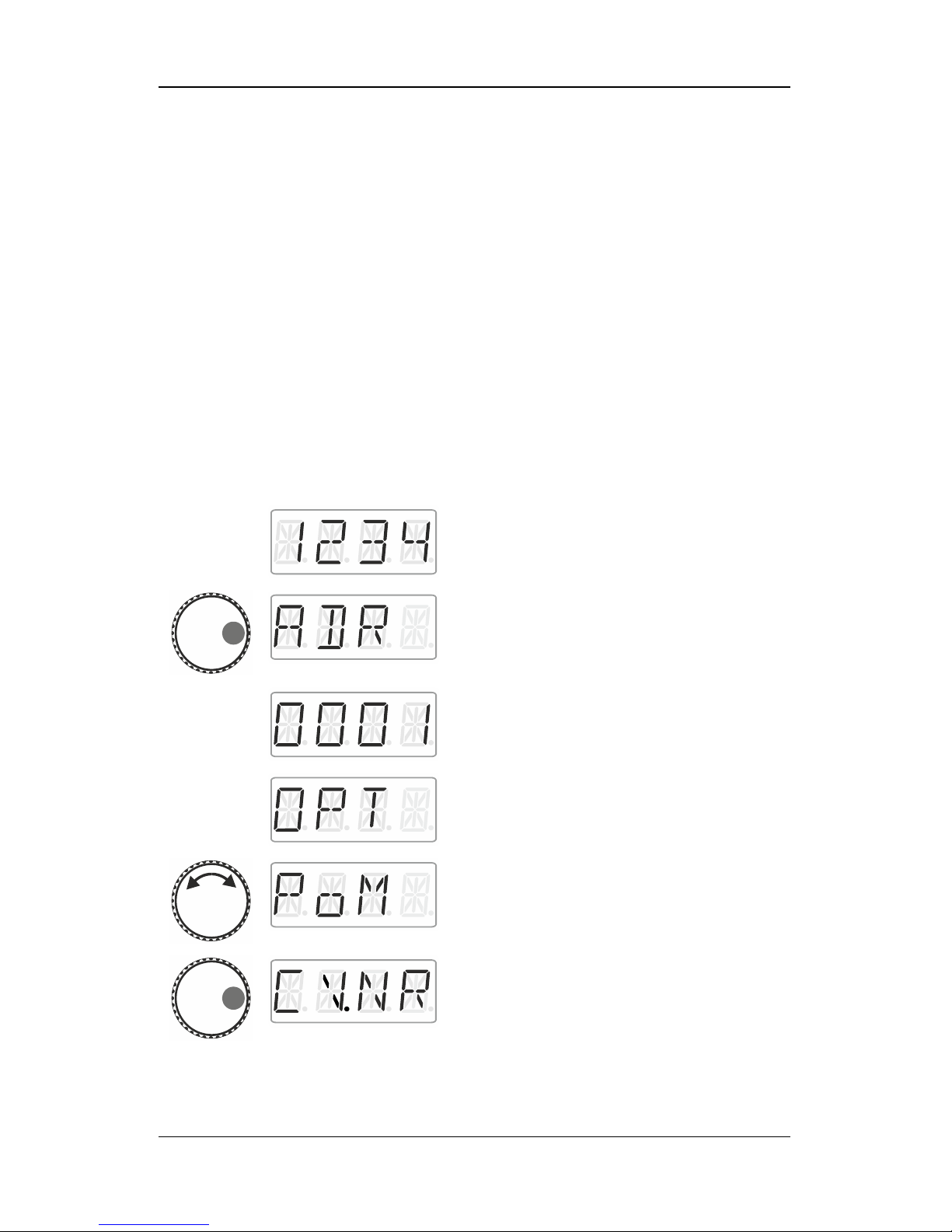
Select the address of the locomotive whose
CVs (settings) you would like to read
(p. 15).
Press the right side of the rotary knob until the
LED to the right shines.
Release the rotary knob to display the
locomotive address used last. Here:
locomotive address 1.
Click right until ‘OPT’ is displayed.
Turn the rotary knob until ‘PoM’ is displayed.
Press right. Now indicate which CV you would
like to read or change.
Page 37
37
Turn the rotary knob and enter the value of
the CV that you would like to read or change.
Proceed as described under setting a
locomotive address (p. 16). The initial value
suggested is CV2.
Press the centre of the rotary knob to enter
the value.
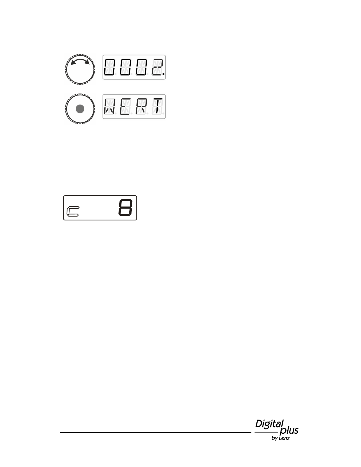
Press the centre of the rotary knob to send a PoM read command to
the decoder which will transmit the content of the CV via RailCom.
The address display LRC120 will receive this information and display
it for approx. 3 seconds ('c' is flashing on the left of the display, the
value is shown on the right).
(Display of the LRC120)
Page 38
38 Information LH01
13 System settings
The system settings are accessed from the top operating level, the
locomotive control.
Action
Display
Explanation
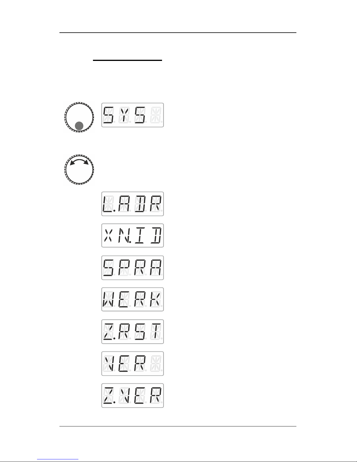
Press the bottom of the rotary knob
until the LED at the bottom shines.
‘SYS’ is displayed, followed by the
first sub menu of the system
settings.
Turn to select one of the following
system settings:
Setting and reading a locomotive
address on the programming track
Setting and reading the XpressNet
address
Language settings
Resetting the LH01
Resetting the command station
(LZV100/LZ100)
Displaying the version number of the
LH01
Displaying the version number of the
command station
Page 39
39
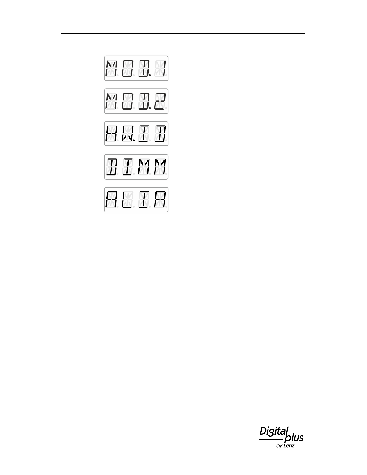
Setting club mode 1
Setting club mode 2
Displaying the hardware ID
Setting the brightness of the display
Enabling/disabling the displaying of
function acronyms
The following sections describe the different system settings.
Page 40
40 Information LH01
13.1 Setting and reading a locomotive address on
the programming track
Place the locomotive whose address you would like to set or read on
the programming track. The programming track is a track section that
is separated from the rest of the layout and connected to terminals P
and Q of the command station LZV100/LZ100. Detailed information on
the programming track can be found in the operating manual of the
LZ100 / LZV100.
Action
Display
Explanation
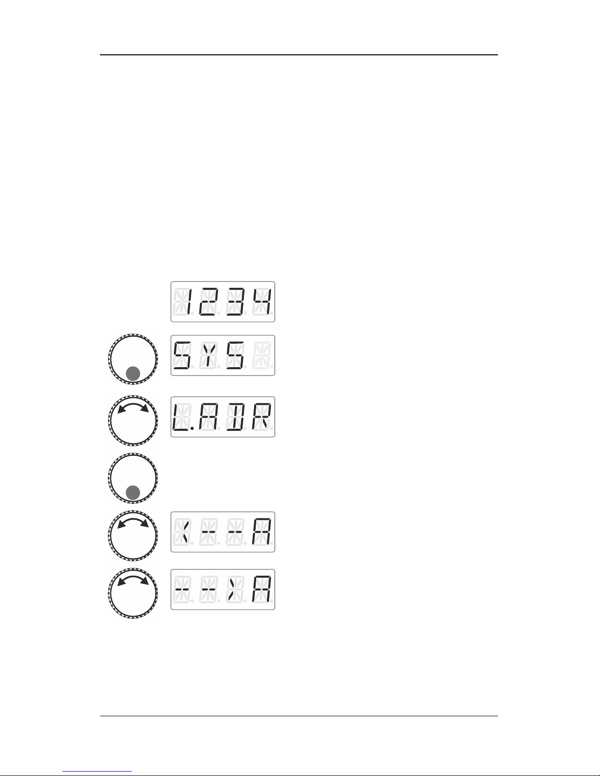
Proceed from ‘Locomotive control’ (address
or speed step are displayed)…
… press the bottom of the rotary knob until
the LED at the bottom shines.
‘SYS’ is displayed, followed by the first sub
menu of the system settings.
Select ‘L.ADR’.
Press the bottom of the rotary knob.
Turn the rotary knob to select
‘Read address’
or
‘Write address’.
Page 41
41
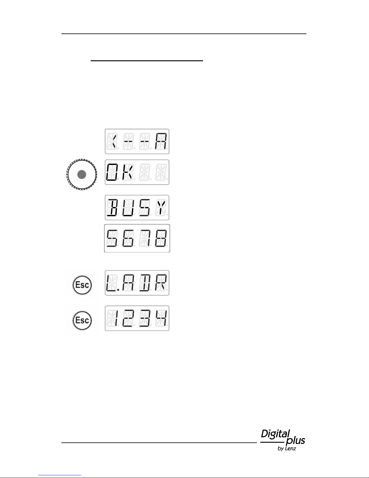
13.1.1 Reading a locomotive address
Place the locomotive whose address you would like to read on the
programming track.
Proceed as described under ‘Setting and reading a locomotive
address on the programming track’.
Action
Display
Explanation
Select ‘Read address’.
Press the centre of the rotary knob to start the
reading process.
The reading process takes some time. The
display shows ‘BUSY’.
Once the reading process is completed, the
identified locomotive address is displayed.
Either
press 'Esc' to return to read/write address and
…
… press 'Esc' to return to ‘Locomotive control’
Page 42
42 Information LH01
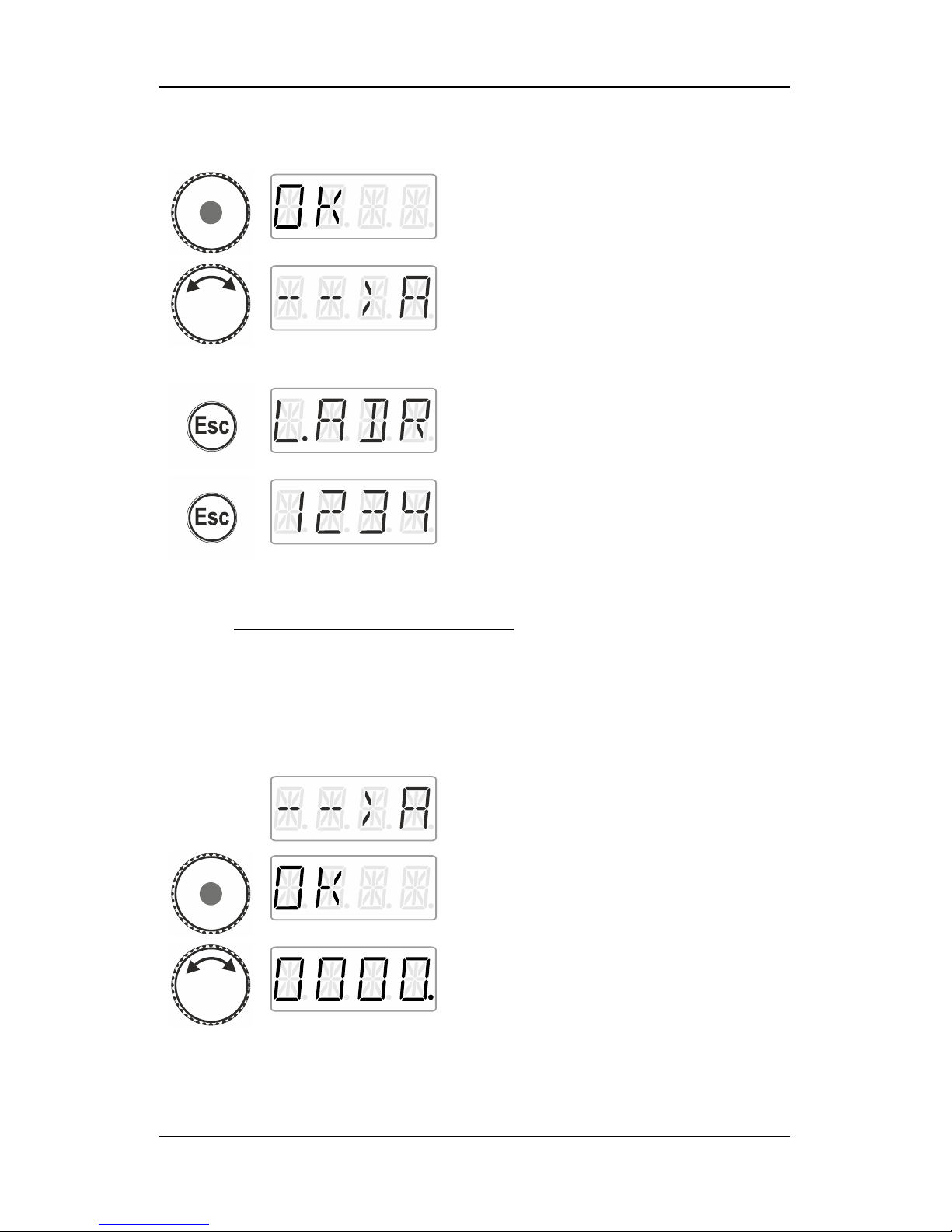
or
press the centre of the rotary knob. The
display shows ‘OK’…
You are back in the menu read/write address.
You can choose between writing an address
(as you may want to change the address that
you have read). In this case, proceed as
described in section "Writing a locomotive
address", p. 42.
Press 'Esc' to return to the system menu.
Turn the rotary knob to select another system
menu or …
... press 'Esc' to return to ‘Locomotive control’.
13.1.2 Writing a locomotive address
Place the locomotive whose address you would like to write on the
programming track.
Proceed as described under ‘Setting and reading a locomotive
address on the programming track ‘.
Action
Display
Explanation
Select ‘Write address’.
Confirm your selection by pressing the centre
of the rotary knob. ‘OK’ is displayed.
Set the address that you would like to write
into the locomotive. To set the address,
proceed as described under ‘Entering a new
locomotive address into the stack‘ (p. 16).
Page 43
43
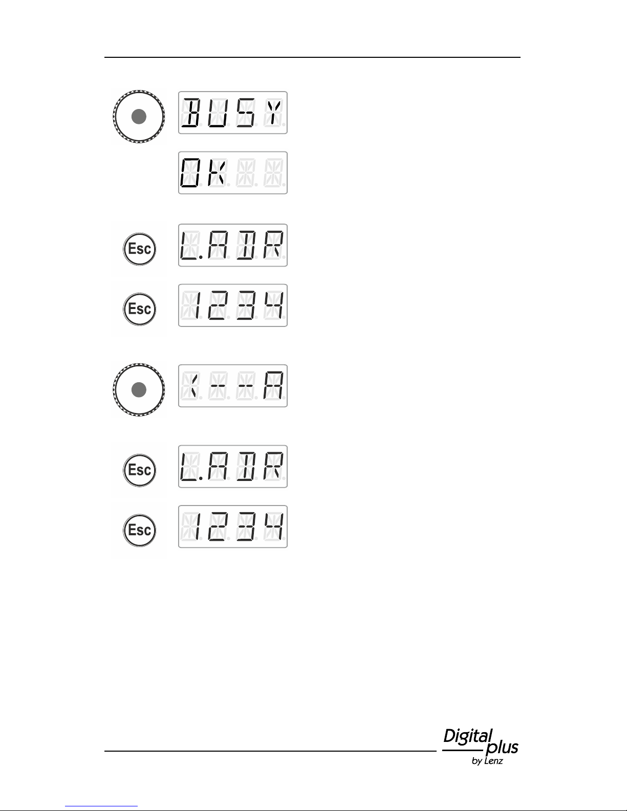
Press the centre of the rotary knob to launch
the writing process. The display shows
‘BUSY’.
If the writing process was successful, ‘OK’
(‘sent’) will be displayed.
Either
press 'Esc' to return to the menu ‘L.ADR’.
You can now select another system menu …
… or press 'Esc' to return to ‘Locomotive
control’.
or
press the centre of the rotary knob. You are
back in the selection/menu read/write
address. You can select between reading an
address to verify the address (proceed as
described in section Reading a locomotive
address, p. 41).
Press 'Esc' to return to the system menu.
Turn to select another system menu …
... or press 'Esc' to return to ‘Locomotive
control’.
Page 44
44 Information LH01
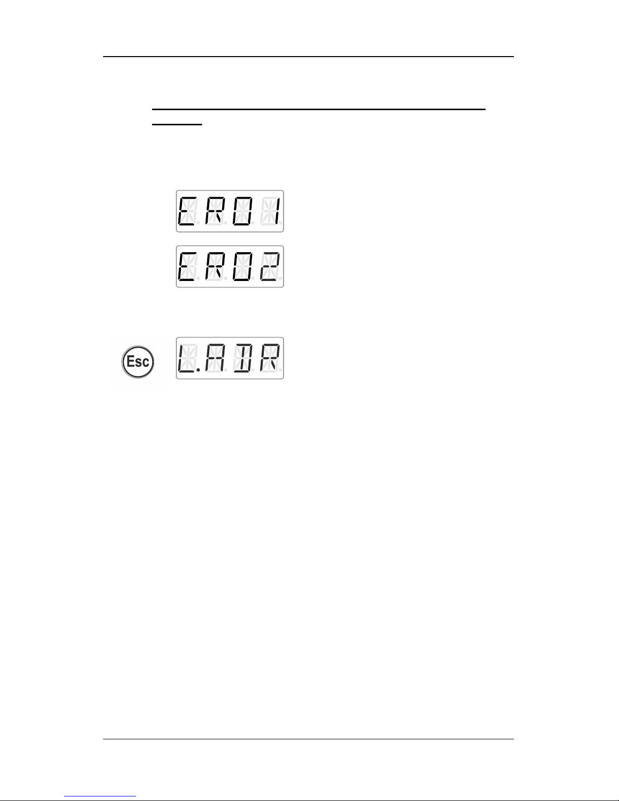
13.1.3 Error messages when reading or writing a locomotive
address
The following error messages may be displayed while reading or
writing a locomotive address:
Action
Display
Explanation
A current overload (short circuit) occurred
during reading or writing. The receiver may
not be connected properly or may be faulty.
The receiver does not respond during reading
or writing, i.e. the receiver may not be
connected properly to the programming
socket of the command station
LZ100/LZV100 (the digital locomotive may not
be placed properly on the programming
track).
Press 'Esc' to return to the system menu
‘L.ADR’.
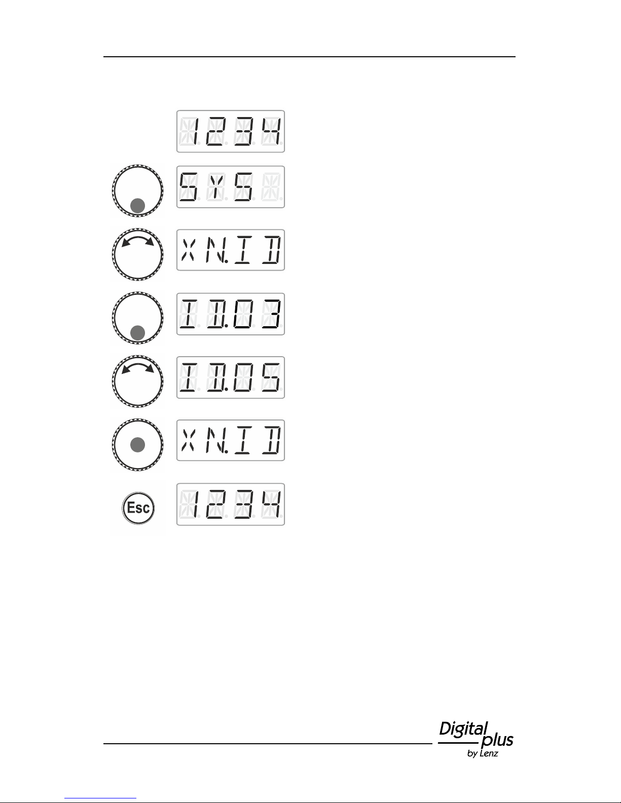
13.2 Setting and reading the XpressNet address
For a fault-free exchange of information with the command station,
each input device connected to XpressNet (XBUS) must have its own
device address. It is, therefore, necessary to ensure that all connected
devices have different addresses. Up to 31 devices can be connected
to the XpressNet, i.e. addresses 1 to 31 can be set. Ex-factory, each
LH01 manual control is set to address 03 (the LH100 is delivered with
address 01, the LH90 with address 02). If you would like to use two or
more manual controls you will have to set a different address for each
control.
Page 45
45
Action
Display
Explanation
Proceed from ‘Locomotive control’ (address
or speed step are displayed)…
… press the bottom of the rotary knob until
the LED at the bottom shines.
‘SYS’ is displayed, followed by the first sub
menu of the system settings.
Select ‘XN.ID’.
Press the bottom of the rotary knob. The
XpressNet address currently set is displayed
(the factory setting is address 3).
Turn to select the desired new XpressNet
address.
Press the centre of the rotary knob to confirm
your selection.
Turn to select another system setting or press
'Esc' to return to ‘Locomotive control’.
Page 46
46 Information LH01
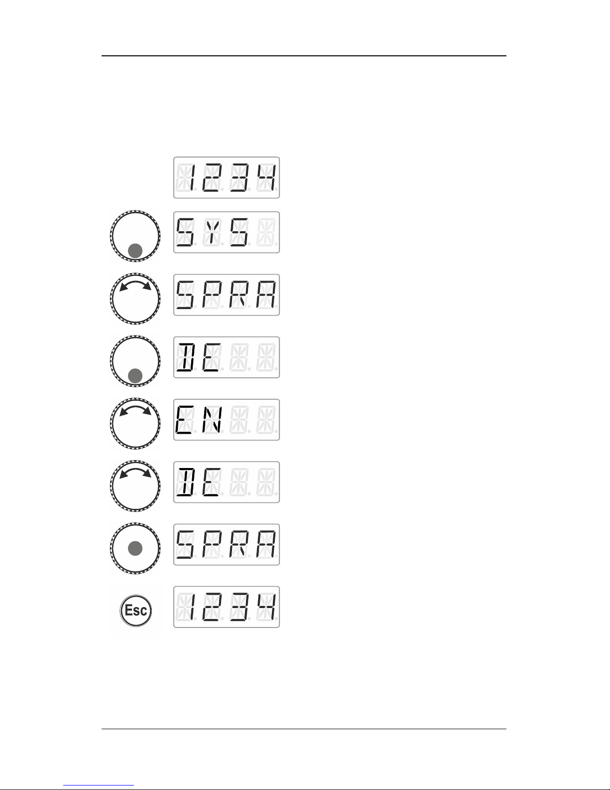
13.3 Setting the language
Action
Display
Explanation
Proceed from ‘Locomotive control’ (address
or speed step are displayed)…
… press the bottom of the rotary knob until
the LED at the bottom shines.
‘SYS’ is displayed, followed by the first sub
menu of the system settings.
Select ‘SPRA’.
Press the bottom of the rotary knob. The
language currently set is displayed.
Turn to select German (DE) or English (EN).
Press the centre of the rotary knob to confirm
your selection.
Turn to select another system setting or press
'Esc' to return to ‘Locomotive control’.
Page 47
47
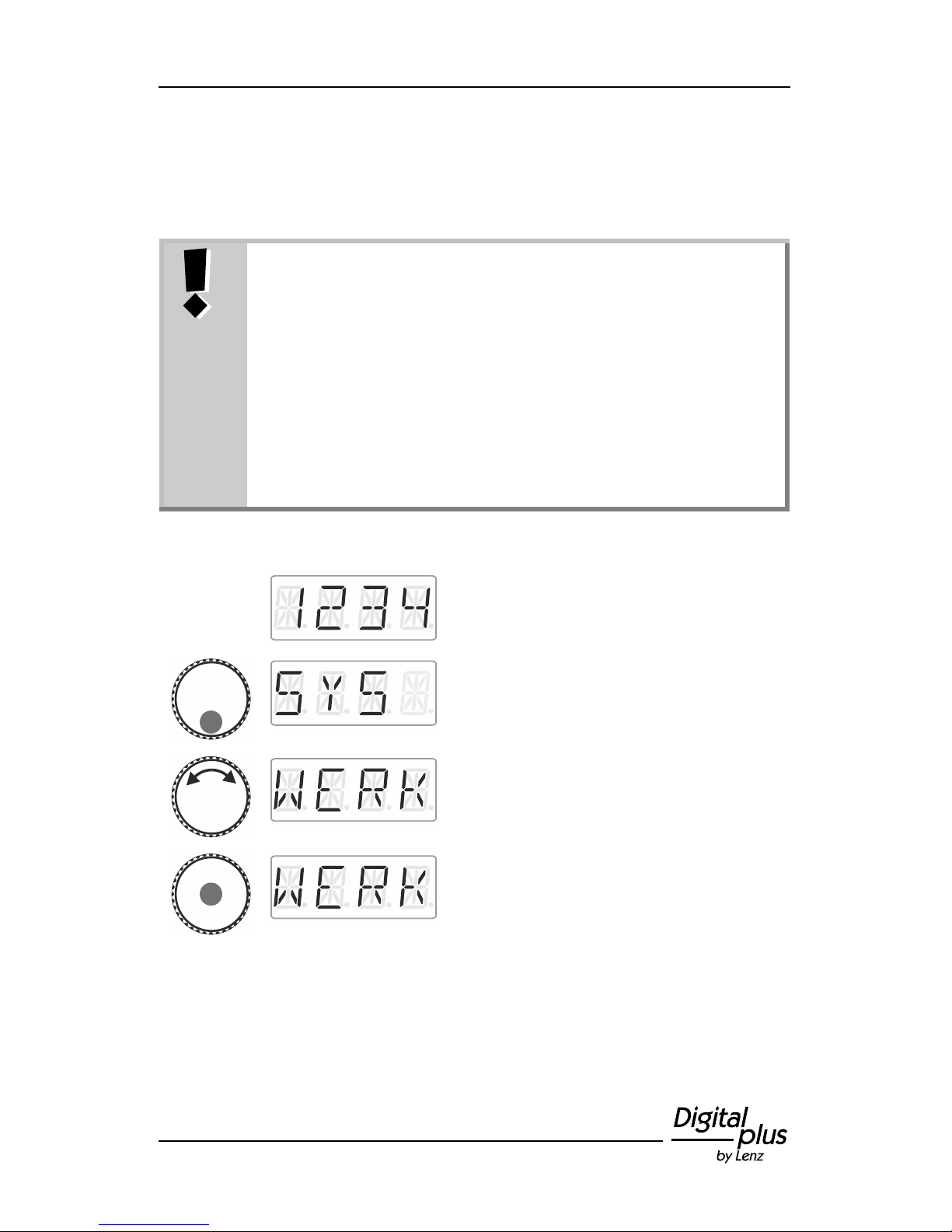
13.4 Resetting the LH01
This system setting resets the factory settings of the LH01.
Resetting the LH01 to the factory settings will delete all
settings made!
- The stack is assigned addresses 1, 2, and 3.
- The function keys are assigned functions F0, F1 and
F2 for these addresses.
- The XpressNet address is set to 3.
- All acronyms are deleted.
- The language is set to German.
- The brightness is set to 100%.
Action
Display
Explanation
Proceed from ‘Locomotive control’ (address
or speed step are displayed)…
… press the bottom of the rotary knob until
the LED at the bottom shines.
‘SYS’ is displayed, followed by the first sub
menu of the system settings.
Select ‘WERK’.
Click the centre of the rotary knob. ‘WERK’
flashes in the display. Press 'Esc' to cancel
the resetting process.
Page 48
48 Information LH01
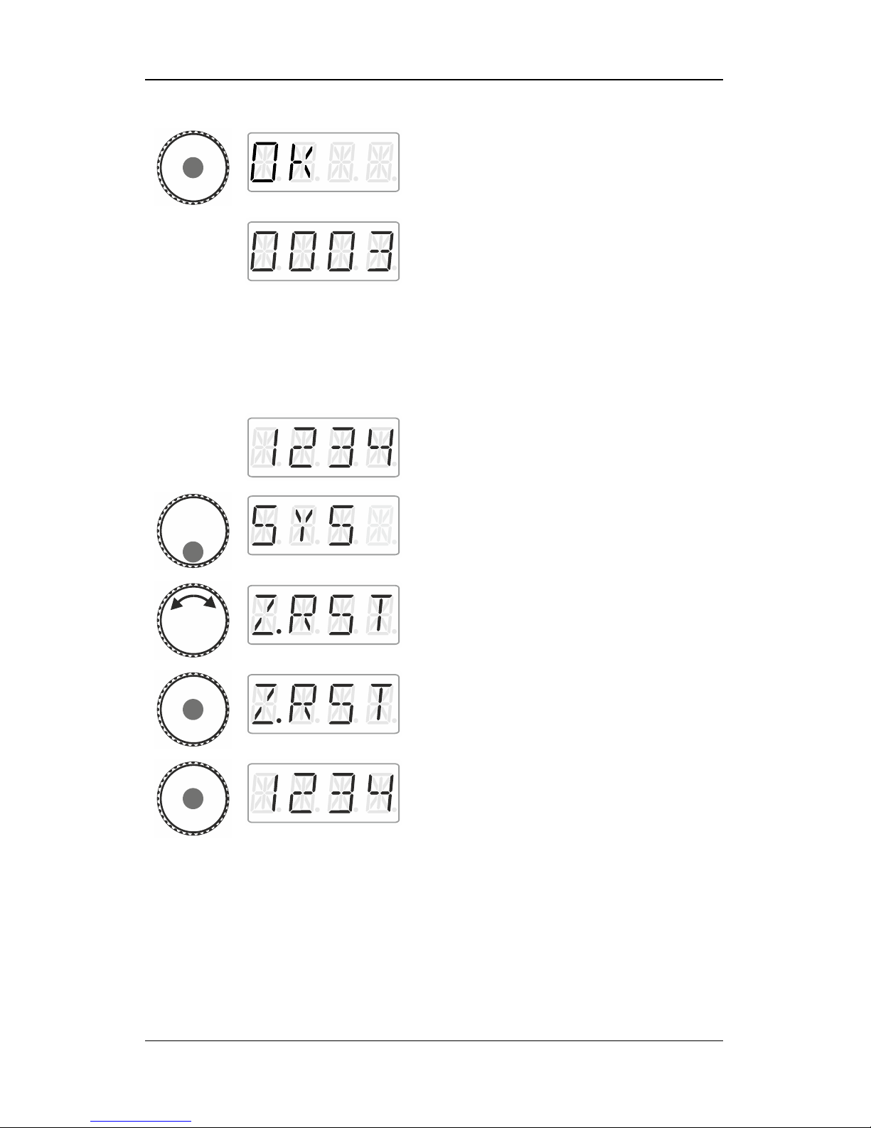
Press the centre of the rotary knob again to
reset the LH01. ‘OK’ is displayed.
You are now in the menu ‘Locomotive
control’. Address ‘0003’ is displayed.
13.5 Resetting command stations (LZV100/LZ100)
Select this option to reset the command station (LZV100 / LZ100).
Action
Display
Explanation
Proceed from ‘Locomotive control’ (address
or speed step are displayed)…
… press the bottom of the rotary knob until
the LED at the bottom shines.
‘SYS’ is displayed, followed by the first sub
menu of the system settings.
Select ‘Z.RST’.
Press the centre of the rotary knob to confirm
your selection. ‘Z.RST’ flashes as a last
warning before resetting. Press 'Esc' to
cancel the resetting process.
Press the centre of the rotary knob again to
reset the command station. You are now in
the menu ‘Locomotive control’.
Page 49
49
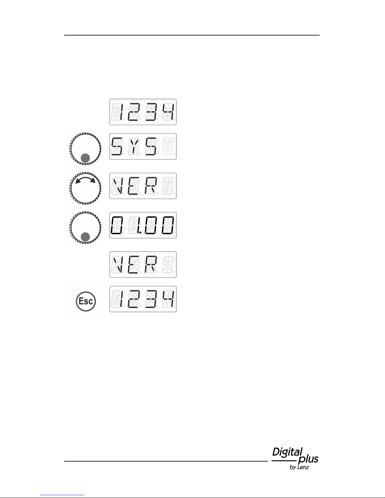
13.6 Displaying the version number of the LH01
Action
Display
Explanation
Proceed from ‘Locomotive control’ (address
or speed step are displayed)…
… press the bottom of the rotary knob until
the LED at the bottom shines.
‘SYS’ is displayed, followed by the first sub
menu of the system settings.
Select ‘VER’.
Press the bottom of the rotary knob to display
the version number of the LH01. Here:
version 1.0.
Release to display the system setting ‘VER’.
Turn the rotary knob to select another system
setting or …
… press 'Esc' to return to ‘Locomotive
control’.
Page 50
50 Information LH01
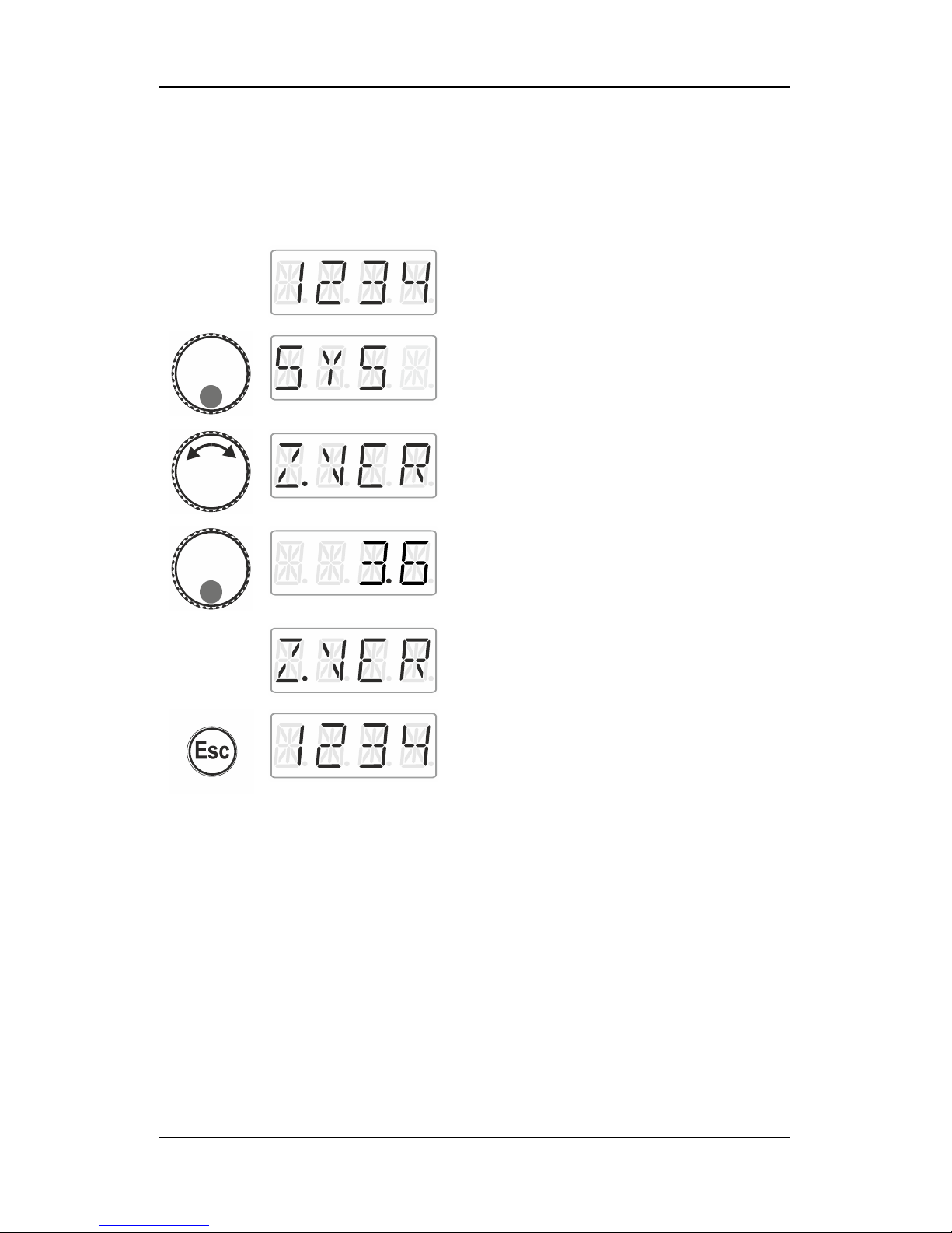
13.7 Displaying the version number of the command
station
Action
Display
Explanation
Proceed from ‘Locomotive control’ (address
or speed step are displayed)…
… press the bottom of the rotary knob until
the LED at the bottom shines.
‘SYS’ is displayed, followed by the first sub
menu of the system settings.
Select ‘Z.VER’.
Press the bottom of the rotary knob to display
the version number of the LH01. Here:
version 3.6.
Release the rotary knob to display the system
setting ‘Z.VER’. Turn the rotary knob to select
another system setting or …
… press 'Esc' to return to ‘Locomotive
control’.
Page 51
51
13.8 Setting the club mode
What is the club mode?
Let us assume that you would like to operate your model railway
layout together with other model railway fans.
To this end, you would like to hand the manual control LH01 to
somebody who has never used the device. You can simplify
operation by hiding most of the operating functions.
Or you would like to prevent someone from selecting a locomotive that
was not assigned to him or her or from making other system settings.
To this end, three modes are available:
Mode 1: It is only possible to control the locomotive set and to
switch the functions assigned to function keys A, B and C.
It is also possible so switch points and signals.
All other operating functions of the LH01 are blocked.
Mode 2: It is only possible to control the locomotive set and to
switch the functions assigned to function keys A, B and C.
All other operating functions of the LH01 are blocked.
Mode 0: This is the factory setting. All settings and functions of the
LH01 are available.
Mode 1 and mode 2 are secured by a password (a 4-digit number).
This password is required to return to mode 0.
Note down the password!
If you forget the password, you will not be able to return to
mode 0.
If you forget the password, please contact our support
service.
Page 52
52 Information LH01
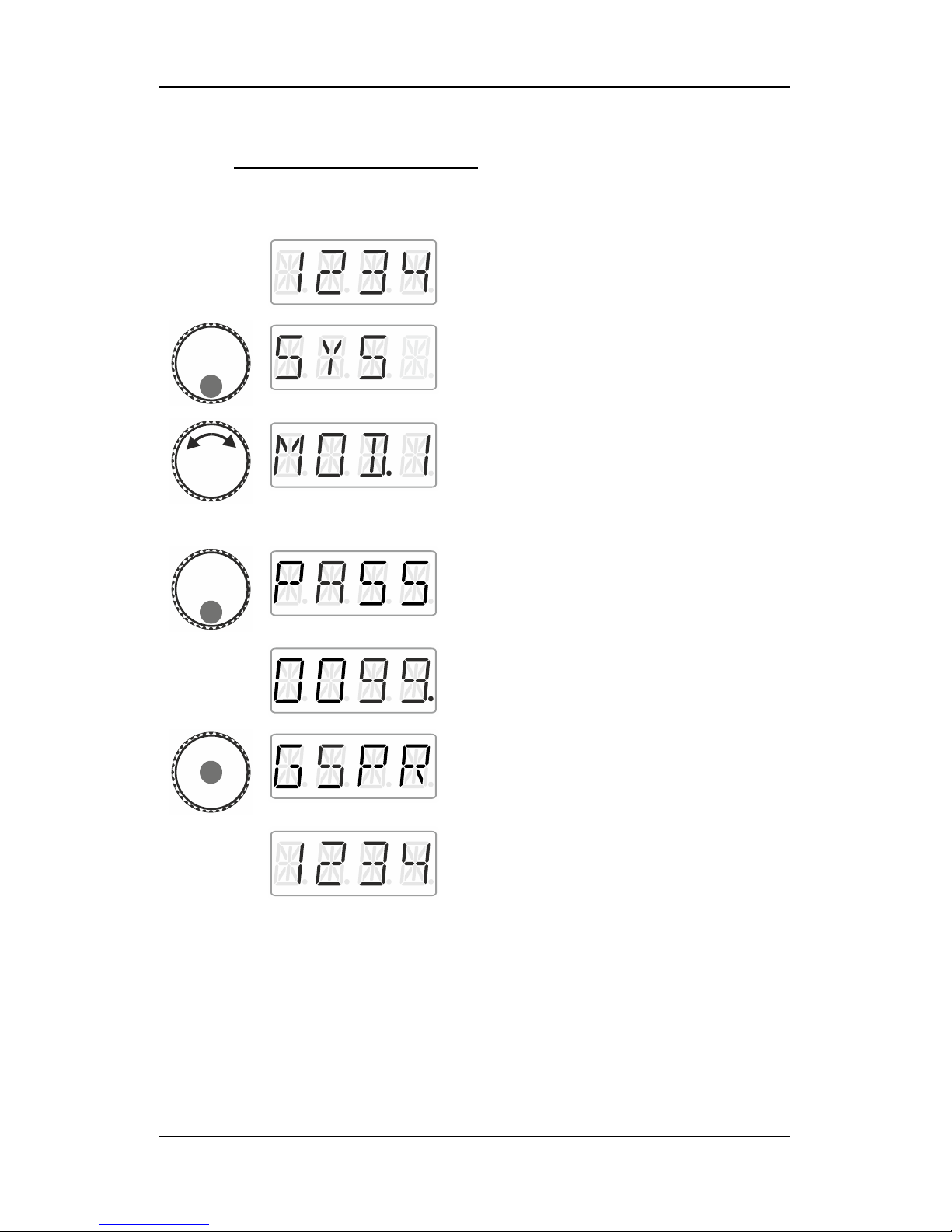
13.8.1 Setting Mode 1 or mode 2
Action
Display
Explanation
Proceed from ‘Locomotive control’ (address
or speed step are displayed)…
… press the bottom of the rotary knob until
the LED at the bottom shines.
‘SYS’ is displayed, followed by the first sub
menu of the system settings.
Select the desired mode.
If the LH01 is set to mode 0, you can select
between ‘MOD.1’ and ‘MOD.2’.
If the LH01 is set to mode 1 or 2, you can only
select ‘MOD.0’.
Press the bottom of the rotary knob to display
‘PASS’. Release the rotary knob
… and the password ‘0099’ will be suggested
to you. Click right or left to select one of the
four digits. Turn the rotary knob to change a
digit and enter the desired password.
Complete the process by pressing the centre
of the rotary knob. ‘GSPR’ is displayed.
The LH01 will automatically return to
‘Locomotive control’. The restrictions of the
selected mode are applied.
Page 53
53
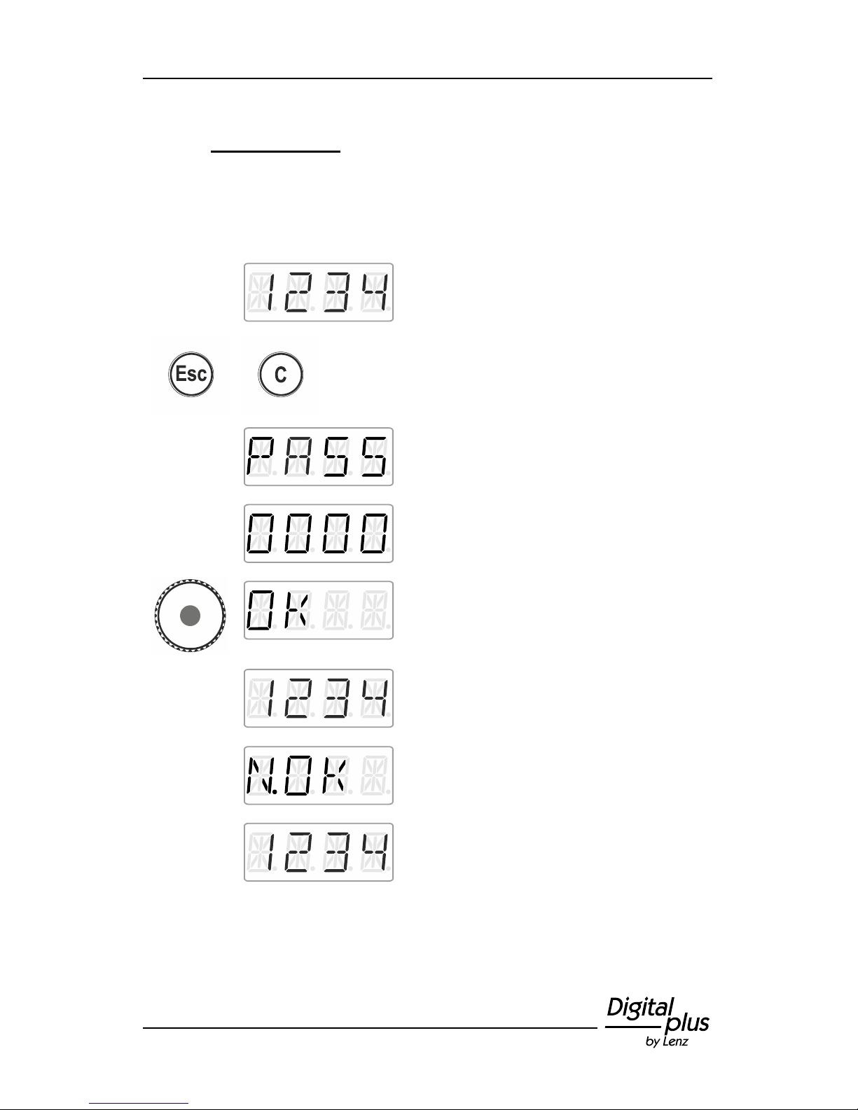
13.8.2 Setting mode 0
If you would like to reset a LH01 that is set to club mode 1 or mode 2
to the ‘normal’ mode, proceed as follows:
Action
Display
Explanation
Proceed from ‘Locomotive control’ (address
or speed step are displayed)…
… press the keys 'Esc' and 'C' simultaneously
to display…
… ‘PASS’.
Release the keys to enter the password.
Press the centre of the rotary knob to confirm
the password.
If you have entered the correct password,
‘OK’ will be displayed …
…and you will return to ‘ Locomotive control’.
The locomotive address or the speed step are
displayed. All functions of the LH01 are
available again.
If you have entered an incorrect password,
‘N.OK’ will be displayed.
The LH01 remains in the selected club mode
and returns to ‘Locomotive control’. The
locomotive address or the speed step are
displayed. Repeat the above steps, using the
correct password.
Page 54
54 Information LH01
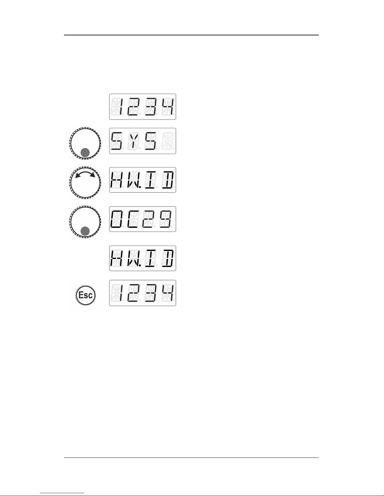
13.9 Displaying the hardware ID
Action
Display
Explanation
Proceed from ‘Locomotive control’ (address
or speed step are displayed)…
… press the bottom of the rotary knob until
the LED at the bottom shines.
‘SYS’ is displayed, followed by the first sub
menu of the system settings.
Select ‘HW.ID’.
Press the bottom of the rotary knob to display
the hardware ID of the LH01. Here: ID 0C29.
Release to display the system setting
‘HW.ID’. Turn the rotary knob to select
another system setting or …
… press 'Esc' to return to ‘Locomotive
control’.
Page 55
55
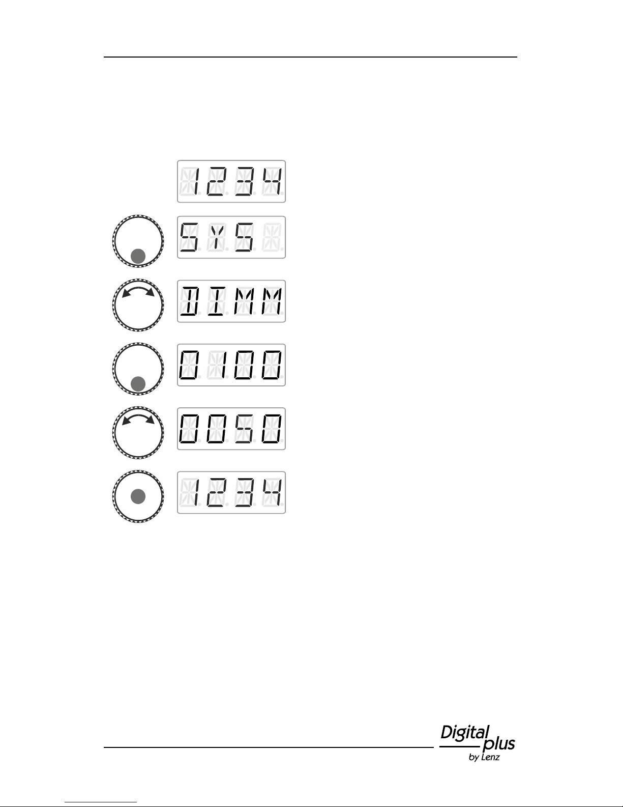
13.10 Setting the brightness of the display
Action
Display
Explanation
Proceed from ‘Locomotive control’ (address
or speed step are displayed)…
… press the bottom of the rotary knob until
the LED at the bottom shines.
‘SYS’ is displayed, followed by the first sub
menu of the system settings.
Select ‘DIMM’.
Press the bottom of the rotary knob. The
brightness value currently set is displayed.
The factory setting is 80%.
Turn the rotary knob to change the brightness
value. The result will be reflected in a change
in brightness.
Click the centre of the rotary knob to confirm
your selection.
Page 56
56 Information LH01
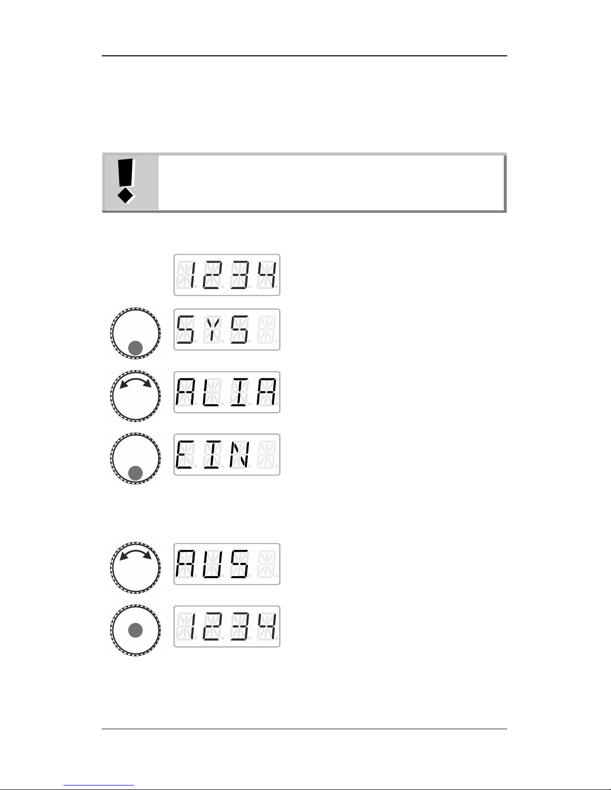
13.11 Enabling/Disabling the displaying of function
acronyms
Function acronyms can only be displayed if you have
assigned acronyms to locomotives functions (p. 24).
Ex-factory, the displaying of acronyms is enabled.
Action
Display
Explanation
Proceed from ‘Locomotive control’ (address
or speed step are displayed)…
… press the bottom of the rotary knob until
the LED at the bottom shines.
‘SYS’ is displayed, followed by the first sub
menu of the system settings.
Select ‘ALIA’ …
… and press the bottom of the rotary knob.
Release the rotary knob to display the
currently set status.
‘EIN’: Function acronyms are displayed.
‘AUS’: Function acronyms are not displayed.
Turn to select the desired status…
… press the centre of the rotary knob to
confirm your selection and return to
‘Locomotive control’.
Page 57

57
14 Technical appendix
14.1 Help in case of malfunction
Malfunction
Cause
Correction
The display of the LH01
remains dark.
Not connected to a power
supply.
Check the cabling of the
XpressNet and connected
devices.
The locomotive address on
the display flashes.
The selected address is
already being used on a
different manual control.
Select a different
locomotive or turn the
rotary knob to take over the
locomotive.
‘AUS’ is displayed.
Another manual control has
triggered an emergency
shutdown.
Press the centre of the
rotary knob to cancel the
emergency shutdown.
The command station or
amplifier has triggered an
emergency shutdown due
to a short circuit.
Remove the short circuit. In
case of an overload divide
the layout into several
power supply sections.
The display is too bright.
The dimming value of the
display has been set to a
maximum.
Decrease the dimming
value.
The display is too dark.
The dimming value of the
display has been set to a
minimum.
Increase the dimming
value.
If you contact us for help in case of malfunctions please provide a
problem description as well as the following information:
Version number of the command station
Version number of the LH01
Designation, version number and service number of all XpressNet
connected XpressNet devices (additional manual controls,
Interface etc.).
This will help us solve the problem. Thank you.
Page 58

58 Information LH01
14.2 List of error messages
Error
Error:
ER01
Programming information: short circuit
ER02
Programming information: no information
ER06
Value outside permissible range
ER07
Command station ready
ER24
DTR/MTR: Locomotive not called up or locomotive address 0
ER25
DTR/MTR: Locomotive called up by another device
ER26
DTR/MTR: Locomotive part of another DTR/MTR
ER27
DTR/MTR: Locomotive speed not 0
ER28
DTR/MTR: Locomotive not part of multiple traction
ER29
DTR/MTR: Locomotive address no multiple traction basic address
ER30
Locomotive cannot be deleted from memory
ER31
Central memory full
ER40
Flash cannot be deleted
ER41
Time-out
ER42
Command station incompatible
ER43
Software incompatible
ER44
Speed step not supported
ER45
Error in locomotive stack
ER80
Transmission error
ER97
Error in data processing at command station LZ100/LZV100
ER98
Command sent to command station by manual control not part of
command range
ER99
General system error
Page 59
59
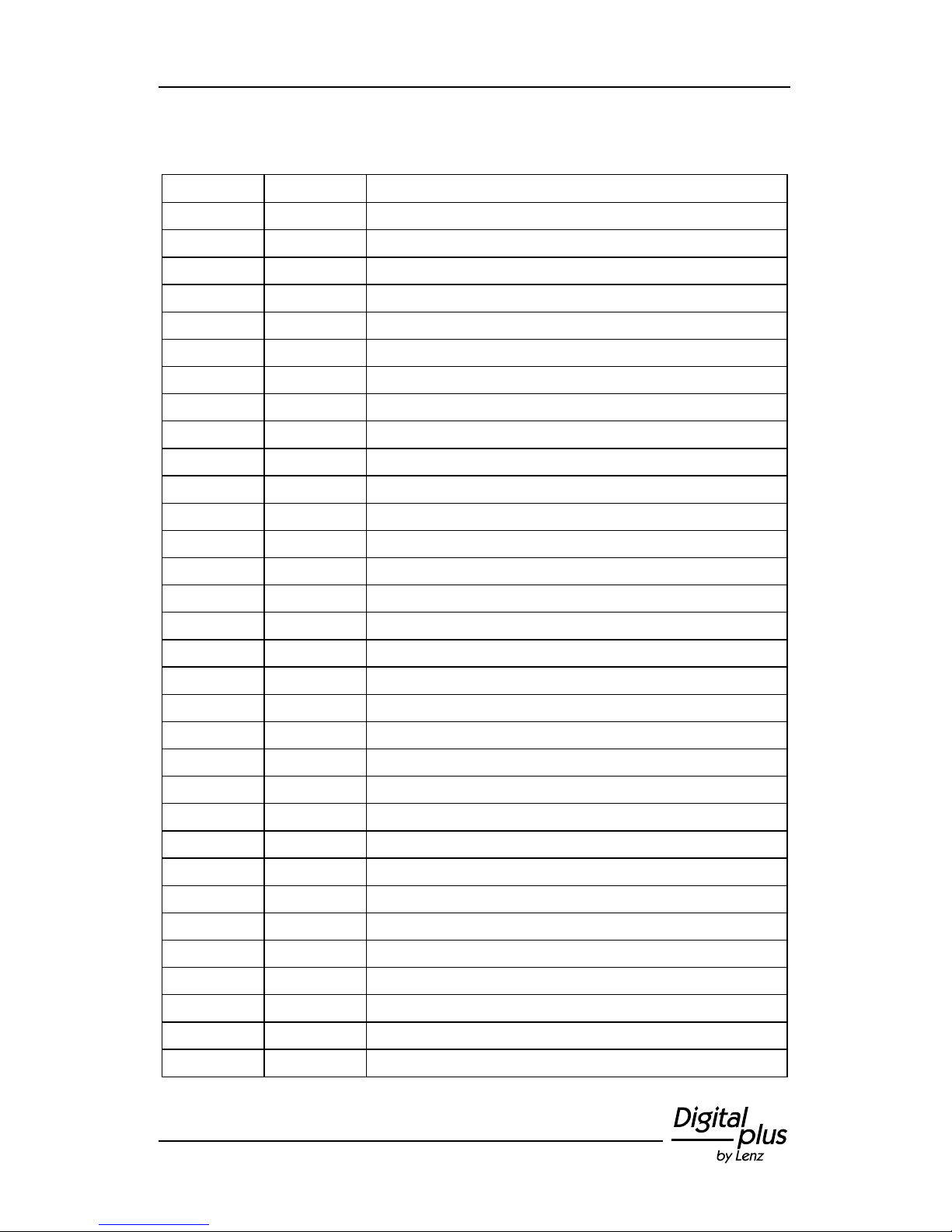
14.3 Display text / Languages
German
English
Meaning
ABBR
ESC
Cancel
ADR
ADR
Address
ALIA
AKA
Display/hide aliases
ANS
SAN
Function text: announcement
AUFL
DISS
Dissolve DTR
AUS
OFF
Function acronyms not displayed
AUS
HALT
Switch off voltage
AUTO
AUTO
Auto mode
BUSY
BUSY
Programming on programming track
CLR
DEL
Delete alias of active function
CR.A
DLA
Delete all aliases of active function
CV.AD
CV.AD
CV address
CV=
CV=
Not used
DAU
CON
Assign switching function to active function
DE
DE
German
DIMM
DIMM
Set display brightness
DPF
SG
Function text: steam
DTR
CCT
Mount double traction
/DTR
/CCT
Unmount double traction
EDIT
EDIT
Edit
EIN
ON
Switch on voltage
EIN
ON
Display function acronyms
EN
EN
English
ENTF
DEL
Remove address
F
F
Prefix for function F0…F28
FAHR
DRIV
Drive
FKT
FCT
Function
F.OPT
F.OPT
Function options
FSM
SSM
Speed step mode
GESE.
SENT
CV value sent
GLO
BL
Function text: bell
GSPR
LOCK
Blocked
Page 60

60 Information LH01
German
English
Meaning
HW.ID
DV.ID
Hardware ID
KUP
CU
Function text: coupling
L.ADR
E.ADR
Read/write locomotive address
LI
LI
Function text: general lighting
LI.F
L.CB
Function text: lighting cabin
LI.H
L.RW
Function text: lighting back
LI.T
L.EG
Function text: lighting driving mechanism
LI.V
L.FW
Function text: lighting front
MAN.
MAN.
Manual mode
MOD.0
MOD.0
Administrator mode
MOD.1
MOD.1
Club mode 1
MOD.2
MOD.2
Club mode 2
MOM
MOM
Assign key function to active function
MOT
EG
Function text: engine
NEU
NEW
Add new address
N.OK
N.OK
Not ok
OK
OK
Confirmation
OPT
OPT
Options
PAN
PG
Function text: pantograph
PASS
CODE
Pass word
PA.H
P.RW
Function text: pantograph back
PA.V
P.FW
Function text: pantograph front
PFE
WH
Function text: whistle
PoM
PoM
Programming in operational mode
PROG
PROG
Programming mode
RA.G
SH
Function text: shunting mode
RATE
RATE
Not used
S.KU
SCU
Function text: coupling sound
SPRA
LANG
Language
STAT
STAT
Status
STOP
STOP
Emergency stop
SYS
SYS
System setting
TEXT
TEXT
Text
TRI
SWH
Function text: thunderer whistle
Page 61
61
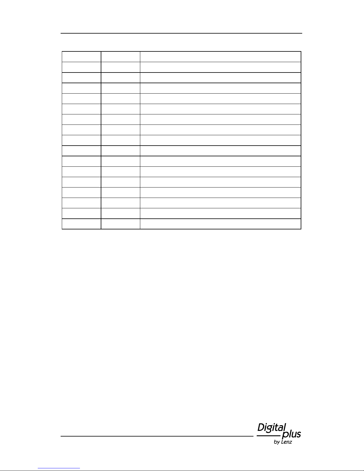
German
English
Meaning
TXT
TXT
Assign alias to active function
UPDA
UPDA
Update
UNLK.
UNLK.
Unblock
WAHL
PICK
Select menu point
WERK
RST
Factory setting
WERT
VAL
CV value
W+S
T+S
Points and signals
VER
VER
Version
XN.ID
XN.ID
XpressNet device address
Z.RST
C.RST
Reset command station
Z.VER
C.VER
Version command station
2.ADR
2.ADR
Second address
-->A
WRIT
Write locomotive address
<--A
READ
Read locomotive address
+
+
Indicator point setting
-
-
Indicator point setting or function status
Page 62

62 Information LH01
This page has been deliberately left blank.
Page 63

63
This page has been deliberately left blank.
Page 64

64 Information LH01
Not suitable for children under fourteen because of the danger of their swallowing the
small constituent pieces. Improper use can result in injury by functionally necessary
points and edges. For use only in dry areas. We reserve the right to make changes in
line with technical progress, product maintenance or changes in production methods.
We accept no responsibility for errors which may occur for similar reasons. We accept
no responsibility for direct or indirect damage resulting from improper use, nonobservance of instructions, use of transformers or other electrical equipment which is
not authorised for use with model railways, or transformers or other electrical equipment
which has been altered or adapted or which is faulty. Nor can we accept responsibility
when damage results from unsupervised adjustments to equipment or from acts of
violence or from overheating or from the effects of moisture etc.. Furthermore, in all
such cases guarantees become invalid.
Vogelsang 14
35398 Giessen
Hotline: 06403 900 133
Fax: 06403 900 155
www.lenz-elektronik.de
Keep this operation manual for future reference!
Art.: B.B.10.0021
 Loading...