

Page 1

LenovoErazerX310HardwareMaintenance
Manual
MachineTypes:90AV[X310ES];90AU[X310Non-ES]
Page 2

Page 3

LenovoErazerX310
HardwareMaintenanceManual
MachineTypes:90AV[X310ES];90AU[X310Non-ES]
Page 4

FirstEdition(June2014)15th
©CopyrightLenovo2014.
LIMITEDANDRESTRICTEDRIGHTSNOTICE:IfdataorsoftwarearedeliveredpursuantaGeneralServices
Administration“GSA”contract,use,reproduction,ordisclosureissubjecttorestrictionssetforthinContractNo.
GS-35F-05925
Page 5

Contents
Chapter1.Aboutthismanual......1
ImportantSafetyInformation..........1
Chapter2.Safetyinformation......3
Generalsafety................3
Electricalsafety...............3
Safetyinspectionguide............5
Handlingelectrostaticdischarge-sensitive
devices..................5
Groundingrequirements............6
Safetynotices................6
Chapter3.Generalinformation.....9
Specifications................9
Chapter4.GeneralCheckout.....11
Chapter5.UsingtheSetupUtility...13
StartingtheLenovoBIOSSetupUtilityprogram.13
Viewingandchangingsettings........13
Usingpasswords..............13
Enablingordisablingadevice........15
Selectingastartupdevice..........16
ExitingtheLenovoBIOSSetupUtilityprogram..17
Chapter6.Symptom-to-FRUIndex..19
Harddiskdrivebooterror..........19
PowerSupplyProblems...........19
AdditionalServiceInformation........19
POSTerrorcodes.............20
Undeterminedproblems...........20
Chapter7.Locations.........23
Identifyinginternalcomponents........23
Identifyingpartsonthesystemboard......23
Chapter8.Replacinghardware....25
Generalinformation.............25
Replacingthekeyboardandmouse......26
Removingthecomputercover........26
Removingthefrontbezel..........27
Replacingamemorymodule.........28
Replacingaharddiskdrive..........28
Replacinganopticaldrive..........29
Replacingagraphicscard..........30
ReplacingthePowersupply.........31
Replacingthemicroprocessorfan.......32
Replacingtheheat-sink...........33
ReplacingtheCPU.............34
ReplacingtheWi-Ficard...........36
Replacingthemotherboard..........37
FRUlists.................38
Chapter9.Generalinformation....45
AdditionalServiceInformation........45
©CopyrightLenovo2014
iii
Page 6

ivLenovoErazerX310HardwareMaintenanceManual
Page 7
Chapter1.Aboutthismanual
ThismanualcontainsserviceandreferenceinformationforLenovoErazerX310computerslistedonthe
cover.ItisintendedonlyfortrainedservicerswhoarefamiliarwithLenovocomputerproducts.
BeforeservicingaLenovoproduct,besuretoreadtheSafetyInformation.
ThedescriptionoftheTVcardinthismanualisonlyusedforthemachineswhichhavetheTVcard.Itis
invalidforthosemachineswhichdonothaveTVcard.
ImportantSafetyInformation
Besuretoreadallcautionanddangerstatementsinthisbookbeforeperforminganyoftheinstructions.
VeuillezliretouteslesconsignesdetypeDANGERetA TTENTIONduprésentdocumentavantd’exécuter
lesinstructions.
LesenSieunbedingtalleHinweisevomTyp“ACHTUNG”oder“VORSICHT”indieserDokumentation,bevor
SieirgendwelcheVorgängedurchführen
LeggereleistruzioniintrodottedaA TTENZIONEePERICOLOpresentinelmanualeprimadieseguireuna
qualsiasidelleistruzioni
Certifique-sedelertodasasinstruçõesdecuidadoeperigonestemanualantesdeexecutarqualquer
umadasinstruções
Esimportantequeleatodaslasdeclaracionesdeprecauciónydepeligrodeestemanualantesdeseguir
lasinstrucciones.
©CopyrightLenovo2014
1
Page 8

2LenovoErazerX310HardwareMaintenanceManual
Page 9

Chapter2.Safetyinformation
Thischaptercontainsthesafetyinformationthatyouneedtobefamiliarwithbeforeservicingacomputer.
Generalsafety
Followtheserulestoensuregeneralsafety:
•Observegoodhousekeepingintheareaofthemachinesduringandaftermaintenance.
•Whenliftinganyheavyobject:
1.Ensureyoucanstandsafelywithoutslipping.
2.Distributetheweightoftheobjectequallybetweenyourfeet.
3.Useaslowliftingforce.Nevermovesuddenlyortwistwhenyouattempttolift.
4.Liftbystandingorbypushingupwithyourlegmuscles;thisactionremovesthestrainfromthe
musclesinyourback.
Donotattempttoliftanyobjectsthatweighmorethan16kg(35lb)orobjectsthatyouthinkare
tooheavyforyou.
•Donotperformanyactionthatcauseshazardstothecustomer,orthatmakestheequipmentunsafe.
•Beforeyoustartthemachine,ensurethatotherservicerepresentativesandthecustomer’spersonnelare
notinahazardousposition.
•Placeremovedcoversandotherpartsinasafeplace,awayfromallpersonnel,whileyouareservicing
themachine.
•Keepyourtoolcaseawayfromwalkareassothatotherpeoplewillnottripoverit.
•Donotwearlooseclothingthatcanbetrappedinthemovingpartsofamachine.Ensurethatyoursleeves
arefastenedorrolledupaboveyourelbows.Ifyourhairislong,fastenit.
•Inserttheendsofyournecktieorscarfinsideclothingorfastenitwithanonconductiveclip,approximately
8centimeters(3inches)fromtheend.
•Donotwearjewelry,chains,metal-frameeyeglasses,ormetalfastenersforyourclothing.
Remember:Metalobjectsaregoodelectricalconductors.
•Wearsafetyglasseswhenyouare:hammering,drillingsoldering,cuttingwire,attachingsprings,using
solvents,orworkinginanyotherconditionsthatmightbehazardoustoyoureyes.
•Afterservice,reinstallallsafetyshields,guards,labels,andgroundwires.Replaceanysafetydevice
thatiswornordefective.
•Reinstallallcoverscorrectlybeforereturningthemachinetothecustomer.
Electricalsafety
CAUTION:
Electricalcurrentfrompower,telephone,andcommunicationcablescanbehazardous.Toavoid
personalinjuryorequipmentdamage,disconnecttheattachedpowercords,telecommunication
systems,networks,andmodemsbeforeyouopenthecomputercovers,unlessinstructedotherwise
intheinstallationandconfigurationprocedures.
©CopyrightLenovo2014
3
Page 10

Observethefollowingruleswhenworkingonelectricalequipment.
Important:Useonlyapprovedtoolsandtestequipment.Somehandtoolshavehandlescoveredwithasoft
materialthatdoesnotinsulateyouwhenworkingwithliveelectricalcurrents.Manycustomershave,near
theirequipment,rubberfloormatsthatcontainsmallconductivefiberstodecreaseelectrostaticdischarges.
Donotusethistypeofmattoprotectyourselffromelectricalshock.
•Findtheroomemergencypower-off(EPO)switch,disconnectingswitch,orelectricaloutlet.Ifanelectrical
accidentoccurs,youcanthenoperatetheswitchorunplugthepowercordquickly.
•Donotworkaloneunderhazardousconditionsornearequipmentthathashazardousvoltages.
•Disconnectallpowerbefore:
–Performingamechanicalinspection
–Workingnearpowersupplies
–RemovingorinstallingFieldReplaceableUnits(FRUs)
•Beforeyoustarttoworkonthemachine,unplugthepowercord.Ifyoucannotunplugit,askthecustomer
topower-offthewallboxthatsuppliespowertothemachineandtolockthewallboxintheoffposition.
•Ifyouneedtoworkonamachinethathasexposedelectricalcircuits,observethefollowingprecautions:
–Ensurethatanotherperson,familiarwiththepower-offcontrols,isnearyou.
Remember:Anotherpersonmustbetheretoswitchoffthepower,ifnecessary.
–Useonlyonehandwhenworkingwithpowered-onelectricalequipment;keeptheotherhandinyour
pocketorbehindyourback.
Remember:Theremustbeacompletecircuittocauseelectricalshock.Byobservingtheaboverule,
youmaypreventacurrentfrompassingthroughyourbody.
–Whenusingatester,setthecontrolscorrectlyandusetheapprovedprobeleadsandaccessoriesfor
thattester.
–Standonsuitablerubbermats(obtainedlocally,ifnecessary)toinsulateyoufromgroundssuchas
metalfloorstripsandmachineframes.
Observethespecialsafetyprecautionswhenyouworkwithveryhighvoltages;theseinstructionsarein
thesafetysectionsofmaintenanceinformation.Useextremecarewhenmeasuringhighvoltages.
•Regularlyinspectandmaintainyourelectricalhandtoolsforsafeoperationalcondition.
•Donotusewornorbrokentoolsandtesters.
•Neverassumethatpowerhasbeendisconnectedfromacircuit.First,checkthatithasbeenpowered-off.
•Alwayslookcarefullyforpossiblehazardsinyourworkarea.Examplesofthesehazardsaremoistfloors,
nongroundedpowerextensioncables,powersurges,andmissingsafetygrounds.
•Donottouchliveelectricalcircuitswiththereflectivesurfaceofaplasticdentalmirror.Thesurfaceis
conductive;suchtouchingcancausepersonalinjuryandmachinedamage.
•Donotservicethefollowingpartswiththepoweronwhentheyareremovedfromtheirnormaloperating
placesinamachine:
–Powersupplyunits
–Pumps
–Blowersandfans
–Motorgenerators
andsimilarunits.(Thispracticeensurescorrectgroundingoftheunits.)
•Ifanelectricalaccidentoccurs:
–Usecaution;donotbecomeavictimyourself.
–Switchoffpower.
4LenovoErazerX310HardwareMaintenanceManual
Page 11

–Sendanotherpersontogetmedicalaid.
Safetyinspectionguide
Theintentofthisinspectionguideistoassistyouinidentifyingpotentiallyunsafeconditionsonthese
products.Eachmachine,asitwasdesignedandbuilt,hadrequiredsafetyitemsinstalledtoprotectusers
andservicepersonnelfrominjury.Thisguideaddressesonlythoseitems.However,goodjudgmentshould
beusedtoidentifypotentialsafetyhazardsduetoattachmentoffeaturesoroptionsnotcoveredbythis
inspectionguide.
Ifanyunsafeconditionsarepresent,youmustdeterminehowserioustheapparenthazardcouldbeand
whetheryoucancontinuewithoutfirstcorrectingtheproblem.
Considertheseconditionsandthesafetyhazardstheypresent:
•Electricalhazards,especiallyprimarypower(primaryvoltageontheframecancauseseriousorfatal
electricalshock).
•Explosivehazards,suchasadamagedCRTfaceorbulgingcapacitor
•Mechanicalhazards,suchaslooseormissinghardware
Theguideconsistsofaseriesofstepspresentedinachecklist.Beginthecheckswiththepoweroff,and
thepowercorddisconnected.
Checklist:
1.Checkexteriorcoversfordamage(loose,broken,orsharpedges).
2.Power-offthecomputer.Disconnectthepowercord.
3.Checkthepowercordfor:
a.Athird-wiregroundconnectoringoodcondition.Useametertomeasurethird-wireground
continuityfor0.1ohmorlessbetweentheexternalgroundpinandframeground.
b.Thepowercordshouldbetheappropriatetypeasspecifiedinthepartslistings.
c.Insulationmustnotbefrayedorworn.
4.Removethecover.
5.Checkforanyobviousalterations.Usegoodjudgmentastothesafetyofanyalterations.
6.Checkinsidetheunitforanyobviousunsafeconditions,suchasmetalfilings,contamination,wateror
otherliquids,orsignsoffireorsmokedamage.
7.Checkforworn,frayed,orpinchedcables.
8.Checkthatthepower-supplycoverfasteners(screwsorrivets)havenotbeenremovedortamperedwith.
Handlingelectrostaticdischarge-sensitivedevices
Anycomputerpartcontainingtransistorsorintegratedcircuits(ICs)shouldbeconsideredsensitiveto
electrostaticdischarge(ESD).ESDdamagecanoccurwhenthereisadifferenceinchargebetweenobjects.
ProtectagainstESDdamagebyequalizingthechargesothatthemachine,thepart,theworkmat,andthe
personhandlingthepartareallatthesamecharge.
Notes:
1.Useproduct-specificESDprocedureswhentheyexceedtherequirementsnotedhere.
2.MakesurethattheESDprotectivedevicesyouusehavebeencertified(ISO9000)asfullyeffective.
WhenhandlingESD-sensitiveparts:
•Keepthepartsinprotectivepackagesuntiltheyareinsertedintotheproduct.
Chapter2.Safetyinformation5
Page 12
•Avoidcontactwithotherpeoplewhilehandlingthepart.
•Wearagroundedwriststrapagainstyourskintoeliminatestaticonyourbody.
•Preventthepartfromtouchingyourclothing.Mostclothingisinsulativeandretainsachargeeven
whenyouarewearingawriststrap.
•Usetheblacksideofagroundedworkmattoprovideastatic-freeworksurface.Thematisespecially
usefulwhenhandlingESD-sensitivedevices.
•Selectagroundingsystem,suchasthoselistedbelow,toprovideprotectionthatmeetsthespecific
servicerequirement.
Note:TheuseofagroundingsystemisdesirablebutnotrequiredtoprotectagainstESDdamage.
–AttachtheESDgroundcliptoanyframeground,groundbraid,orgreen-wireground.
–UseanESDcommongroundorreferencepointwhenworkingonadouble-insulatedor
battery-operatedsystem.Y oucanusecoaxorconnector-outsideshellsonthesesystems.
–Usetheroundground-prongoftheacplugonac-operatedcomputers.
Groundingrequirements
Electricalgroundingofthecomputerisrequiredforoperatorsafetyandcorrectsystemfunction.Proper
groundingoftheelectricaloutletcanbeverifiedbyacertifiedelectrician.
Safetynotices
ThecautionanddangersafetynoticesinthissectionareprovidedinthethelanguageofEnglish.
DANGER
Electricalcurrentfrompower,telephoneandcommunicationcablesishazardous.
Toavoidashockhazard:
•Donotconnectordisconnectanycablesorperforminstallation,maintenance,orreconfiguration
ofthisproductduringanelectricalstorm.
•Connectallpowercordstoaproperlywiredandgroundedelectricaloutlet.
•Connecttoproperlywiredoutletsanyequipmentthatwillbeattachedtothisproduct.
•Whenpossible,useonehandonlytoconnectordisconnectsignalcables.
•Neverturnonanyequipmentwhenthereisevidenceoffire,water,orstructuraldamage.
•Disconnecttheattachedpowercords,telecommunicationssystems,networks,andmodems
beforeyouopenthedevicecovers,unlessinstructedotherwiseintheinstallationandconfiguration
procedures.
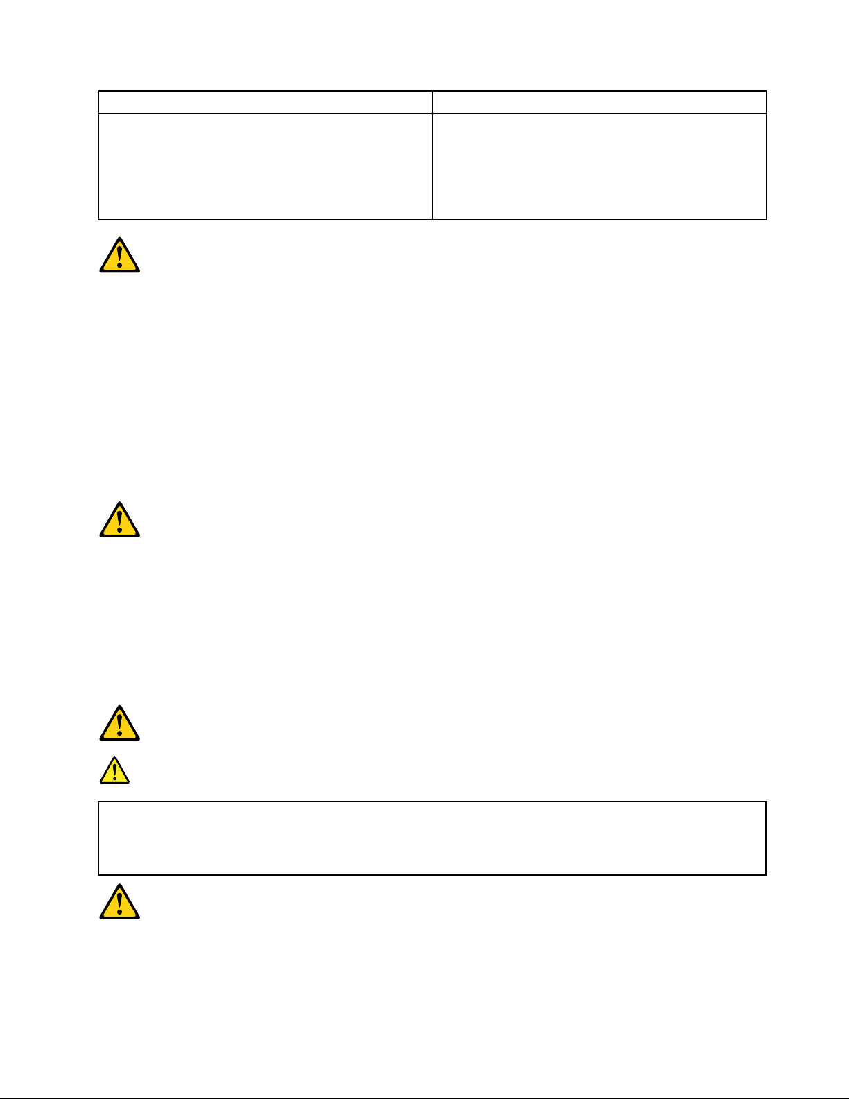
•Connectanddisconnectcablesasdescribedinthefollowingtablewheninstalling,moving,or
openingcoversonthisproductorattacheddevices.
6LenovoErazerX310HardwareMaintenanceManual
Page 13
ToConnect
1.TurneverythingOFF .
2.First,attachallcablestodevices.
3.Attachsignalcablestoconnectors.
4.Attachpowercordstooutlet.
5.TurndeviceON.
ToDisconnect
1.TurneverythingOFF .
2.First,removepowercordsfromoutlet.
3.Removesignalcablesfromconnectors.
4.Removeallcablesfromdevices.
CAUTION:
Whenreplacingthelithiumbattery,useonlyPartNumber45C1566oranequivalenttypebattery
recommendedbythemanufacturer.Ifyoursystemhasamodulecontainingalithiumbattery,replace
itonlywiththesamemoduletypemadebythesamemanufacturer.Thebatterycontainslithiumand
canexplodeifnotproperlyused,handled,ordisposedof.
Donot:
•Throworimmerseintowater
•Heattomorethan100°C(212°F)
•Repairordisassemble
Disposeofthebatteryasrequiredbylocalordinancesorregulations.
CAUTION:
Whenlaserproducts(suchasCD-ROMs,DVD-ROMdrives,fiberopticdevices,ortransmitters)are
installed,notethefollowing:
•Donotremovethecovers.Removingthecoversofthelaserproductcouldresultinexposureto
hazardouslaserradiation.Therearenoserviceablepartsinsidethedevice.
•Useofcontrolsoradjustmentsorperformanceofproceduresotherthanthosespecifiedherein
mightresultinhazardousradiationexposure.
DANGER
SomelaserproductscontainanembeddedClass3AorClass3Blaserdiode.Notethefollowing:
Laserradiationwhenopen.Donotstareintothebeam,donotviewdirectlywithoptical
instruments,andavoiddirectexposuretothebeam.
Chapter2.Safetyinformation7
Page 14
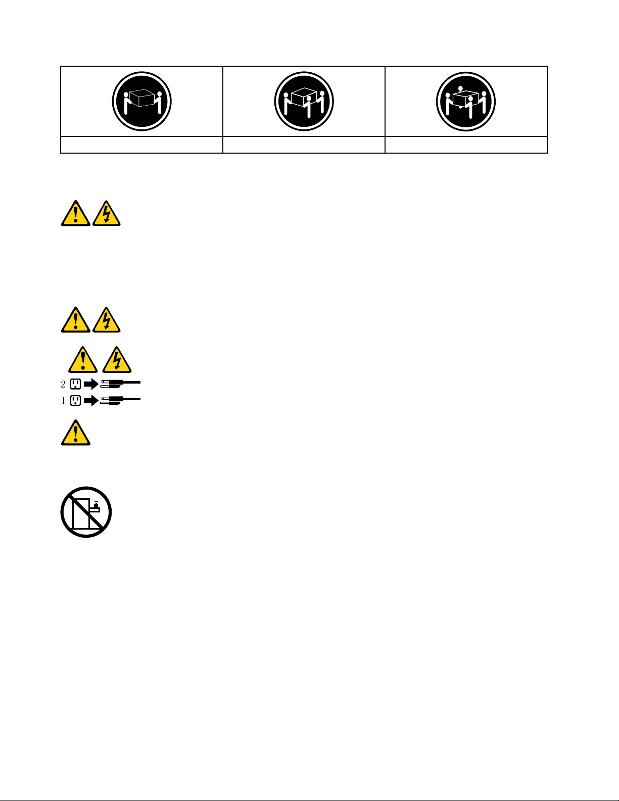
≥18kg(37lbs)≥32kg(70.5lbs)≥55kg(121.2lbs)
CAUTION:
Usesafepracticeswhenlifting.
CAUTION:
Thepowercontrolbuttononthedeviceandthepowerswitchonthepowersupplydonotturnoff
theelectricalcurrentsuppliedtothedevice.Thedevicealsomighthavemorethanonepower
cord.Toremoveallelectricalcurrentfromthedevice,ensurethatallpowercordsaredisconnected
fromthepowersource.
CAUTION:
Donotplaceanyobjectweighingmorethan82kg(180lbs.)ontopofrack-mounteddevices.
8LenovoErazerX310HardwareMaintenanceManual
Page 15

Chapter3.Generalinformation
Thischapterprovidesgeneralinformationthatappliestoallmachinetypessupportedbythispublication.
Specifications
Thissectionliststhephysicalspecificationsforyourcomputer.
Thissectionliststhephysicalspecificationsforyourcomputer .
TypeLenovoErazerX310
Thissectionliststhephysicalspecifications.
Environment
Airtemperature:
Operating:10°to35°C
Transit:-20°to55°C
Humidity:
Operating:35%to80%
Transit:20%to90%(40°C)
Altitude:86KPato106KPa
Electricalinput:
Inputvoltage:90V-264V(AC)
Inputfrequency:47Hz-63Hz
©CopyrightLenovo2014
9
Page 16

10LenovoErazerX310HardwareMaintenanceManual
Page 17

Chapter4.GeneralCheckout
Attention:Thedrivesinthecomputeryouareservicingmighthavebeenrearrangedorthedrivestartup
sequencechanged.Beextremelycarefulduringwriteoperationssuchascopying,saving,orformatting.
Dataorprogramscanbeoverwrittenifyouselectanincorrectdrive.
Generalerrormessagesappearifaproblemorconflictisfoundbyanapplicationprogram,theoperating
system,orboth.Foranexplanationofthesemessages,refertotheinformationsuppliedwiththatsoftware
package.
Usethefollowingproceduretohelpdeterminethecauseoftheproblem:
1.Power-offthecomputerandallexternaldevices.
2.Checkallcablesandpowercords.
3.Setalldisplaycontrolstothemiddleposition.
4.Power-onallexternaldevices.
5.Power-onthecomputer.
•Lookfordisplayederrorcodes
•Lookforreadableinstructionsoramainmenuonthedisplay.
Ifyoudidnotreceivethecorrectresponse,proceedtostep6.
Ifyoudoreceivethecorrectresponse,proceedtostep7.
6.Lookatthefollowingconditionsandfollowtheinstructions:
•IfthecomputerdisplaysaPOSTerror,goto“POSTerrorcodes” .
•Ifthecomputerhangsandnoerrorisdisplayed,continueatstep7.
7.Iftheteststopsandyoucannotcontinue,replacethelastdevicetested.
©CopyrightLenovo2014
11
Page 18

12LenovoErazerX310HardwareMaintenanceManual
Page 19

Chapter5.UsingtheSetupUtility
TheSetupUtilityprogramisusedtoviewandchangetheconfigurationsettingsofyourcomputer,regardless
ofwhichoperatingsystemyouareusing.However,theoperating-systemsettingsmightoverrideanysimilar
settingsintheSetupUtilityprogram.
StartingtheLenovoBIOSSetupUtilityprogram
TostarttheLenovoBIOSSetupUtilityprogram,dothefollowing:
1.Ifyourcomputerisalreadyonwhenyoustartthisprocedure,shutdowntheoperatingsystemand
turnoffthecomputer.
2.PressandholdtheF1keythenturnonthecomputer.WhentheLenovoBIOSSetupUtilityprogramis
displayed,releasetheF1key.
Note:IfaPower-OnPasswordoranAdministratorPasswordhasbeenset,theSetupUtilityprogrammenu
isnotdisplayeduntilyoutypeyourpassword.Formoreinformation,see“Usingpasswords.”
Viewingandchangingsettings
SystemconfigurationoptionsarelistedintheLenovoBIOSSetupUtilityprogrammenu.Tovieworchange
settings,see“StartingtheSetupUtilityprogram. ”
YoumustusethekeyboardwhenusingtheLenovoBIOSSetupUtilitymenu.Thekeysusedtoperform
varioustasksaredisplayedonthebottomofeachscreen.
Usingpasswords
YoucanusetheLenovoBIOSSetupUtilityprogramtosetpasswordstopreventunauthorizedpersons
fromgainingaccesstoyourcomputeranddata.See“StartingtheSetupUtilityprogram. ”Thefollowing
typesofpasswordsareavailable:
•SetAdministratorPassword
•SetPower-OnPassword
Youdonothavetosetanypasswordstouseyourcomputer.However,ifyoudecidetosetpasswords,read
thefollowingsections.
Passwordconsiderations
Apasswordcanbeanycombinationoflettersandnumbersupto16character(a-z,and0-9).Forsecurity
reasons,itisagoodideatouseastrongpasswordthatcannotbeeasilycompromised.Wesuggestthat
passwordsshouldfollowtheserules:
•Strongpasswordscontain7-16characters,combinelettersandnumbers.
•Donotuseyournameoryourusername.
•Donotuseacommonwordoracommonname.
•Besignificantlydifferentfromyourpreviouspassword.
Attention:AdministratorandPower-Onpasswordsarenotcasesensitive
©CopyrightLenovo2014
13
Page 20

AdministratorPassword
SettinganAdministratorPassworddetersunauthorizedpersonsfromchangingconfigurationsettings.You
mightwanttosetanAdministratorPasswordifyouareresponsibleformaintainingthesettingsofseveral
computers.
AfteryousetanAdministratorPassword,apasswordpromptisdisplayedeverytimeyouaccesstheLenovo
BIOSSetupUtilityprogram.
IfboththeAdministratorandPower-OnPasswordareset,youcantypeeitherpassword.However,youmust
useyourAdministratorPasswordtochangeanyconfigurationsettings.
Setting,changing,ordeletinganAdministratorpassword
TosetanAdministratorPassword,dothefollowing:
Note:Apasswordcanbeanycombinationoflettersandnumbersupto16character(a-z,and0-9).For
moreinformation,see“Passwordconsiderations”onpage13.
1.StarttheLenovoBIOSSetupUtilityprogram(see“StartingtheLenovoBIOSSetupUtilityprogram”on
page13).
2.FromtheSecuritymenu,selectSetAdministratorPasswordandpresstheEnterkey.
3.Thepassworddialogboxwillbedisplayed.TypethepasswordthenpresstheEnterkey.
4.Re-typethepasswordtoconfirm,thenpresstheEnterkey.Ifyoutypethepasswordcorrectly,the
passwordwillbeinstalled.
TochangeanAdministratorPassword,dothefollowing:
1.StarttheLenovoBIOSSetupUtilityprogram(see“StartingtheLenovoBIOSSetupUtilityprogram”on
page13).
2.FromtheSecuritymenu,selectSetAdministratorPasswordandpresstheEnterkey.
3.Thepassworddialogboxwillbedisplayed.TypethecurrentpasswordthenpressEnterkey.
4.Typethenewpassword,thenpressEnterkey.Re-typethepasswordtoconfirmthenewpassword,if
youtypethenewpasswordcorrectly,thenewpasswordwillbeinstalled.ASetupNoticewilldisplay
thatchangeshavebeensaved.
TodeleteapreviouslysetAdministratorPassword,dothefollowing:
1.FromtheSecuritymenu,selectSetAdministratorPasswordandpresstheEnterkey.
2.Thepassworddialogboxwillbedisplayed.TypethecurrentpasswordandpresstheEnterkey.
3.TodeleteanAdministratorPassword,Enterblankfieldsforeachnewpasswordlineitem.Asetup
noticewilldisplaythatchangeshavebeensaved.
4.ReturntotheLenovoBIOSSetupUtilityprogrammenuandselecttheExitoption.
5.SelectSavechangesandExitfromthemenu.
Power-OnPassword
WhenaPower-OnPasswordisset,youcannotstarttheLenovoBIOSSetupUtilityprogramuntilavalid
passwordistypedfromthekeyboard.
Setting,changing,ordeletingaPower-OnPassword
Note:Apasswordcanbeanycombinationoflettersandnumbersupto16character(a-z,and0-9).
14LenovoErazerX310HardwareMaintenanceManual
Page 21

TosetaPower-OnPassword,dothefollowing:
1.StarttheLenovoBIOSSetupUtilityprogram(See”StartingtheLenovoBIOSSetupUtilityprogram”on
page13.)
2.FromtheSecuritymenu,selectSetPower-OnPasswordandpresstheEnterkey.
3.Thepassworddialogboxwillbedisplayed.Typethepassword,andpresstheEnterkey.
4.Re-typethepasswordtoconfirm,ifyoutypethepasswordcorrectly,thepasswordwillbeinstalled.
TochangeaPower-OnPassword,dothefollowing:
1.StarttheLenovoBIOSSetupUtilityprogram(See”StartingtheLenovoBIOSSetupUtilityprogram”on
page13.)
2.FromtheSecuritymenu,selectSetPower-OnPasswordandpresstheEnterkey.
3.Thepassworddialogboxwillbedisplayed.TypethecurrentpasswordthenpresstheEnterkey.
4.Typethenewpassword,thenpresstheEnterkey.Re-typethepasswordtoconfirmthenewpassword,
ifyoutypethenewpasswordcorrectly,thenewpasswordwillbeinstalled.Asetupnoticewilldisplay
thatchangeshavebeensaved.
TodeleteapreviouslysetPower-OnPassword,dothefollowing:
1.FromtheSecuritymenu,selectSetPower-OnPasswordandpresstheEnterkey.
2.Thepassworddialogboxwillbedisplayed.TypethecurrentpasswordandpresstheEnterkey.
3.TodeletethePower-OnPassword,Enterblankfieldsforeachnewpasswordlineitem.Asetup
noticewilldisplaythatchangeshavebeensaved.
4.ReturntotheLenovoBIOSSetupUtilityprogrammenuandselecttheExitoption.
5.SelectSavechangesandExitfromthemenu.
Enablingordisablingadevice
TheDevicesoptionsisusedtoenableordisableuseraccesstothefollowingdevices:
USBFunctionsSelectwhethertoenableordisableUSB(UniversalSerial
Bus)functions.Ifthefunctionsaredisabled,noUSB
devicescanbeused.
ATADriveSetupSelectIDEorACHImode.Devicedriversupportis
requiredforACHImode.Dependingonhowtheharddisk
imagewasinstalled,changingthissettingmayprevent
thesystemfrombooting.
OnboardAudioControllerSelectwhethertoenableordisabletheOnboardAudio
Controller,whenfeatureissettoDisabledalldevices
connectedtotheaudioconnectors(e.g.aheadphoneor
amicrophone)aredisabledandcan’tbeused.
OnboardEthernetControllerorBootAgentSelectwhethertoenableordisableOnboardEthernet
Controller,orselectwhethertoenableordisableload
onboardPXE(PrebootExecutionEnvironment),or
SMC(SecureManagedClient).Thisfeaturewillallow
thecomputertobootfromaserverimage.
Toenableordisableadevice,dothefollowing:
1.StarttheSetupUtilityprogram(see“StartingtheSetupUtilityprogram”onpage13).
2.FromtheSetupUtilityprogrammenu,selectDevices.
3.Select:
Chapter5.UsingtheSetupUtility15
Page 22

USBSetuppresstheEnterkey,andthenselectUSBFunctions.
ATADeviceSetuppresstheEnterkey.SelectConfigureSA T Aas,presstheEnterkeyandthen
selectSATAmode.
AudioSetuppresstheEnterkey,andthenselectOnboardAudioController.
NetworkSetuppresstheEnterkey,thenselectOnboardEthernetSupportorBootAgent.
4.SelectDisabledorEnabledandpresstheEnterkey.
5.ReturntotheLenovoBIOSSetupUtilityprogrammenuandselecttheExitoption.
6.SelectSavechangesandExitfromthemenu.
Note:Ifyoudonotwanttosavethesettings,selectDiscardchangesandExitfromthemenu.
Selectingastartupdevice
IfyourcomputerdoesnotbootfromadevicesuchastheCD/DVD-ROMdrivediskorharddiskasexpected,
followoneoftheproceduresbelow.
Selectingatemporarystartupdevice
Usethisproceduretostartupfromanybootdevice.
Note:NotallCDs,DVDsorharddiskdrivesarebootable.
1.Turnoffyourcomputer.
2.PressandholdtheF12keythenturnonthecomputer.WhentheStartupDeviceMenuappears,
releasetheF12key.
Note:IftheStartupDeviceMenudoesnotdisplayusingthesesteps,repeatedlypressandreleasethe
F12keyratherthankeepingitpressedwhenturningonthecomputer.
3.Use↑and↓arrowstoselectthedesiredstartupdevicefromtheStartupDeviceMenuandpress
theEnterkeytobegin.
Note:SelectingastartupdevicefromtheStartupDeviceMenudoesnotpermanentlychangethe
startupsequence.
Selectingorchangingthestartupdevicesequence
Tovieworpermanentlychangetheconfiguredstartupdevicesequence,dothefollowing:
1.StarttheLenovoBIOSSetupUtilityprogram(see“StartingtheLenovoBIOSSetupUtilityprogram”on
page13).
2.FromtheLenovoBIOSSetupUtilityprogrammainmenu,selecttheStartupoption.
3.PresstheEnterkey,andselectthedevicesforthePrimaryBootSequence.Readtheinformation
displayedontherightsideofthescreen.
4.Use↑and↓arrowstoselectadevice.Usethe<+>or<->keystomoveadeviceupordown.Usethe
<×>keytoexcludethedevicefromorincludethedeviceinthebootsequence.
5.ReturntotheLenovoBIOSSetupUtilityprogrammenuandselecttheExitoption.
6.SelectSavechangesandExitfromthemenu.
Notes:
a.Ifyoudonotwanttosavethesettings,selectDiscardchangesandExitfromthemenu.
16LenovoErazerX310HardwareMaintenanceManual
Page 23

b.Ifyouhavechangedthesesettingsandwanttoreturntothedefaultsettings,selectLoadOptimal
Defaultsfromthemenu.
ExitingtheLenovoBIOSSetupUtilityprogram
Afteryoufinishviewingorchangingsettings,presstheEsckeytoreturntotheLenovoBIOSSetupUtility
programmainmenu.Y oumighthavetopresstheEsckeyseveraltimes.Dooneofthefollowing:
•Ifyouwanttosavethenewsettings,selectSavechangesandExitfromthemenu.WhentheSave&
resetwindowshows,selecttheY esbutton,andthenpresstheEnterkeytoexittheLenovoBIOS
SetupUtilityprogram.
•Ifyoudonotwanttosavethesettings,selectDiscardchangesandExitfromthemenu.Whenthe
ResetWithoutSavingwindowshows,selecttheY esbutton,andthenpresstheEnterkeytoexitthe
SetupUtilityprogram.
Chapter5.UsingtheSetupUtility17
Page 24

18LenovoErazerX310HardwareMaintenanceManual
Page 25
Chapter6.Symptom-to-FRUIndex
TheSymptom-to-FRUindexlistserrorsymptomsandpossiblecauses.Themostlikelycauseislistedfirst.
AlwaysbeginwithChapter4,“GeneralCheckout, ”onpage11.Thisindexcanalsobeusedtohelpyou
decidewhichFRUstohaveavailablewhenservicingacomputer.Ifyouareunabletocorrecttheproblem
usingthisindex,goto“Undeterminedproblems”onpage20.
Notes:
•Ifyouhavebothanerrormessageandanincorrectaudioresponse,diagnosetheerrormessagefirst.
•Ifyoucannotrunthediagnostictestsoryougetadiagnosticerrorcodewhenrunningatestbutdid
receiveaPOSTerrormessage,diagnosethePOSTerrormessagefirst.
•Ifyoudidnotreceiveanyerrormessagelookforadescriptionofyourerrorsymptomsinthefirstpartof
thisindex.
Harddiskdrivebooterror
Aharddiskdrivebooterrorcanhavethefollowingcauses.
Error
Thestartupdriveisnotincludedinthebootsequence
inconfiguration.
Nooperatingsysteminstalledonthebootdrive.Installanoperatingsystemonthebootdrive.
Thebootsectoronthestartupdriveiscorrupted.
Thedriveisdefective.
FRU/Action
Checktheconfigurationandensurethestartupdriveis
inthebootsequence.
Thedrivemustbeformatted.Dothefollowing:
1.Attempttoback-upthedataonthefailingharddisk
drive.
2.Usetheoperatingsystemtoformattheharddisk
drive.
Replacetheharddiskdrive.
PowerSupplyProblems
Followtheseproceduresifyoususpectthereisapowersupplyproblem.
Check/VerifyFRU/Action
Checkthatthefollowingareproperlyinstalled:
•PowerCord
•On/OffSwitchconnector
•SystemBoardPowerSupplyconnectors
•Microprocessor(s)connection
Checkthepowercord.PowerCord
Checkthepower-onswitch.Power-onSwitch
Reseatconnectors
AdditionalServiceInformation
Thischapterprovidesadditionalinformationthattheservicerepresentativemightfindhelpful.
©CopyrightLenovo2014
19
Page 26
Powermanagement
Powermanagementreducesthepowerconsumptionofcertaincomponentsofthecomputersuchasthe
systempowersupply,processor,harddiskdrives,andsomemonitors.
Advancedconfigurationandpowerinterface(ACPI)BIOS
AsthiscomputerhasanACPIBIOSsystem,theoperatingsystemisallowedtocontrolthepower
managementfeaturesofthecomputerandthesettingsforAdvancedPowerManagement(APM)BIOSmode
isignored.NotalloperatingsystemssupportACPIBIOSmode.
AutomaticPower-Onfeatures
TheAutomaticPower-OnfeatureswithinthePowerManagementmenuallowyoutoenableanddisable
featuresthatturnonthecomputerautomatically.
•WakeUponAlarm:Y oucanspecifyadateandtimeatwhichthecomputerwillbeturnedonautomatically.
Thiscanbeeitherasingleevent,adailyeventoraweeklyevent.
•WakeUponLAN:ThisfeatureallowsLANadaptercardtowaketheSystem.
POSTerrorcodes
Eachtimeyouturnthecomputeron,itperformsaseriesofteststocheckthatthesystemisoperating
correctlyandthatcertainoptionsareset.ThisseriesoftestsiscalledthePower-OnSelf- T est,orPOST.
POSTdoesthefollowing:
•Checkssomebasicsystem-boardoperations
•Checksthatthememoryisworkingcorrectly
•Startsvideooperations
•Verifiesthatthebootdriveisworking
POSTErrorMessageDescription/Action
Keyboarderror
RebootandSelectproperBootdeviceorInsertBoot
MediainselectedBootdevice
Cannotinitializethekeyboard.Makesurethekeyboard
isproperlyconnectedtothecomputerandthatnokeys
areheldpressedduringPOST.Topurposelyconfigure
thecomputerwithoutakeyboard,selectKeyboardless
operationinStartupoptiontoEnabled.TheBIOSthen
ignoresthemissingkeyboardduringPOST.
TheBIOSwasunabletofindasuitablebootdevice.Make
surethebootdriveisproperlyconnectedtothecomputer.
Makesureyouhavebootablemediainthebootdevice.
Undeterminedproblems
1.Power-offthecomputer.
2.Removeordisconnectthefollowingcomponents(ifconnectedorinstalled)oneatatime.
a.Externaldevices(modem,printer,ormouse)
b.Extendedvideomemory
c.ExternalCache
d.ExternalCacheRAM
e.Harddiskdrive
f.Diskdrive
20LenovoErazerX310HardwareMaintenanceManual
Page 27

3.Power-onthecomputertore-testthesystem.
4.Repeatsteps1through3untilyoufindthefailingdeviceorcomponent.
Ifalldevicesandcomponentshavebeenremovedandtheproblemcontinues,replacethesystemboard.
Chapter6.Symptom-to-FRUIndex21
Page 28

22LenovoErazerX310HardwareMaintenanceManual
Page 29
Chapter7.Locations
1
2
3
4
5
6
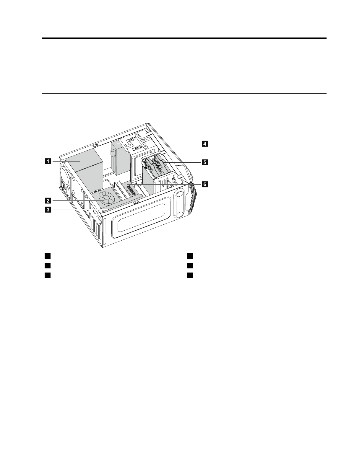
Thissectionprovidesillustrationstohelplocatethevariousconnectors,controlsandcomponentsofthe
computer.
Identifyinginternalcomponents
Thefollowingillustrationshowsthecomponentsinsideyourcomputer.
1Powersupply
2Microprocessorfanandheatsink
3Graphicscard6Systemboard
4Opticaldiskdrive
5Harddiskdrive
Identifyingpartsonthesystemboard
Thesystemboard(alsoknownasthe“mainboard”or“motherboard”)isthemaincircuitboardinyour
computer.Itprovidesbasiccomputerfunctionsandsupportsavarietyofdevicesthatarefactory-installed
orthatyoucaninstalllater.
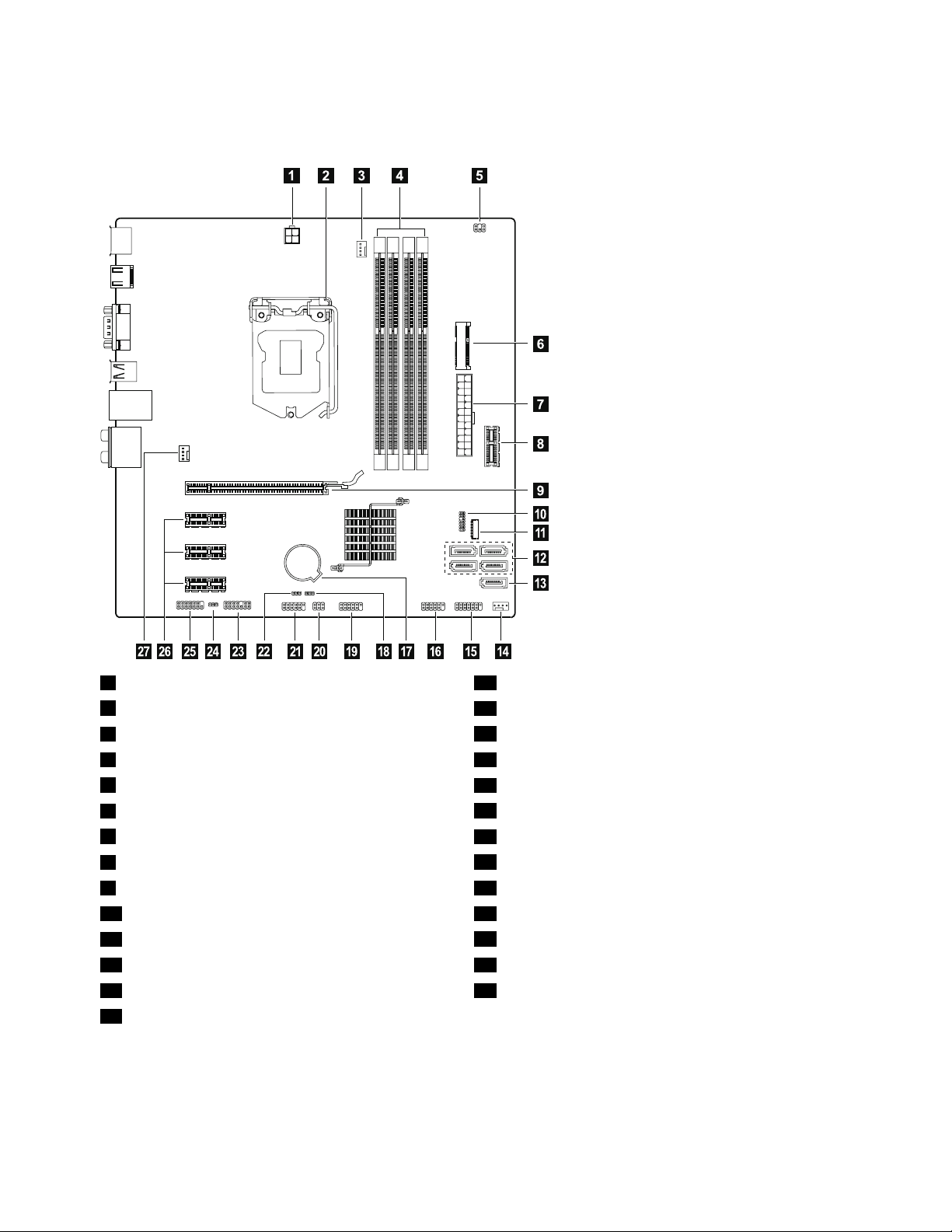
Thefollowingillustrationsshowthelocationsofthedifferentpartsonthesystemboard.
©CopyrightLenovo2014
23
Page 30
X310
1 2 3 4
7
6
8
9
5
15161718 14
10
11
2122 20 19
12
13
2324252627
112Vpowerconnector15Frontpanelconnector
2Microprocessorandheatsink
3Microprocessorfanheader
4Memoryslots(4)18ClearCMOSjumper
5Thermalsensorheader
6MiniPCI-Eslot
7Powerconnector
8FrontUSB3.0slot
9PCIexpressX16adapterslot23LPCdebugconnector
10SPIdebugconnector24ClearCMOSjumper
11Solidstatediskpowerconnector
12SA TAconnectors(4)26PCIexpressX1adapterslots(3)
13eSA TAconnector27Systemfanheader
14Powerfanheader
16FrontUSB2.0connector
17Battery
19FrontUSB3.0connector
20Modeswitchconnector
21Serial(COM2)connector
22MEdisablejumper
25Frontaudioconnector
24LenovoErazerX310HardwareMaintenanceManual
Page 31

Chapter8.Replacinghardware
Attention:Donotremovethecomputercoverorattemptanyrepairbeforereadingthe“Importantsafety
information”intheSafetyandWarrantyGuidethatwasincludedwithyourcomputer.Toobtaincopiesofthe
SafetyandWarrantyGuide,gototheSupportWebsiteat:
http://consumersupport.lenovo.com
Generalinformation
Pre-disassemblyinstructions
Beforeproceedingwiththedisassemblyprocedure,makesurethatyoudothefollowing:
1.Turnoffthepowertothesystemandallperipherals.
2.Unplugallpowerandsignalcablesfromthecomputer.
3.Placethesystemonaflat,stablesurface.
Generalinformation
Pre-disassemblyinstructions
Beforeproceedingwiththedisassemblyprocedure,makesurethatyoudothefollowing:
1.Turnoffthepowertothesystemandallperipherals.
2.Unplugallpowerandsignalcablesfromthecomputer.
3.Placethesystemonaflat,stablesurface.
©CopyrightLenovo2014
25
Page 32
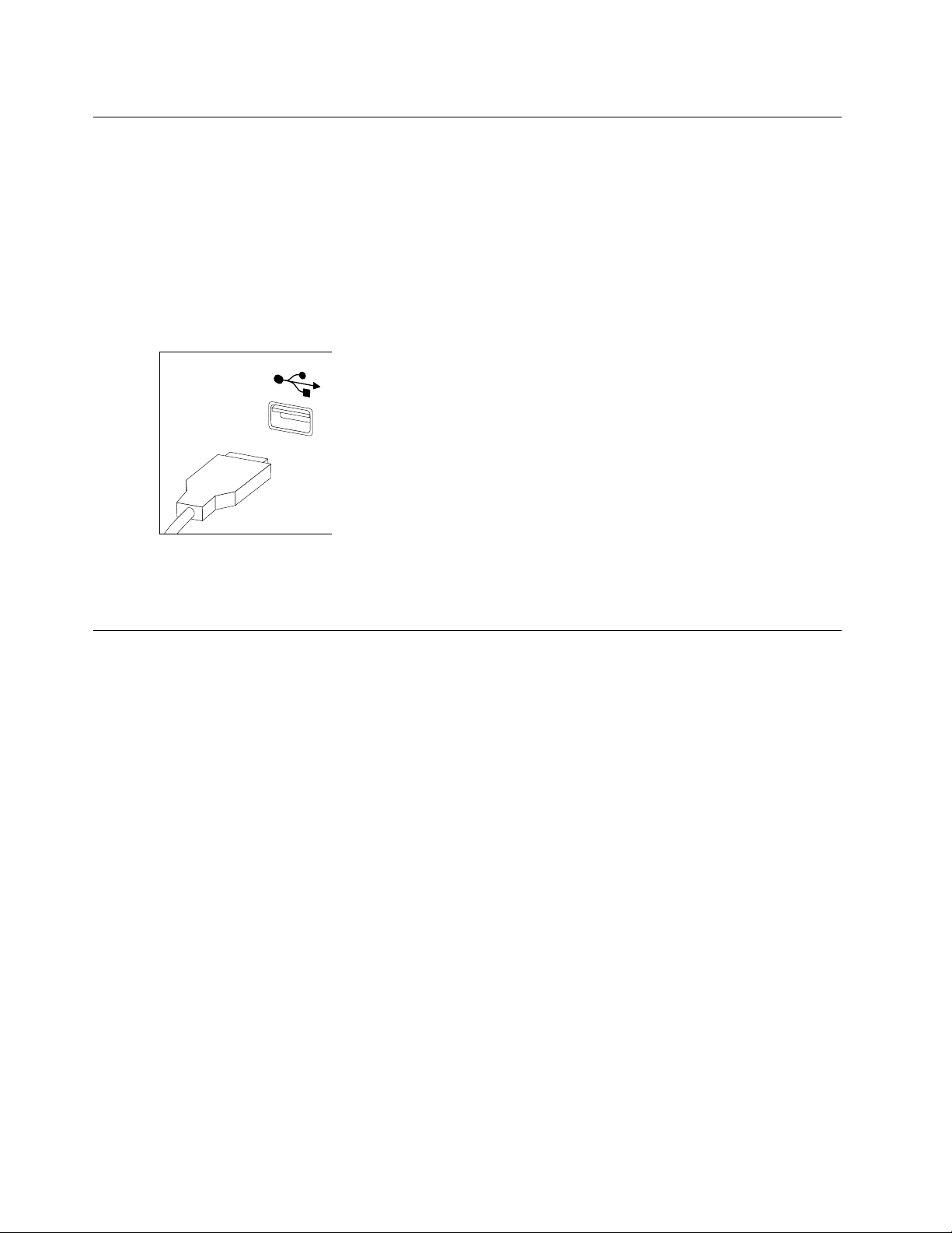
Replacingthekeyboardandmouse
Note:YourkeyboardwillbeconnectedtoaUSBconnectorateitherfrontorattherearofthecomputer.
Toreplacethekeyboard:
Step1.Removeanymedia(disks,CDs,ormemorycards)fromthedrives,shutdownthecomputer,and
turnoffallattacheddevices.
Step2.Unplugallpowercordsfromelectricaloutlets.
Step3.Locatetheconnectorforthekeyboard.Referto“Frontviewofthechassis”and“Rearviewofthe
chassis”.
Step4.Disconnectthedefectivekeyboardcablefromthecomputerandconnectthenewkeyboardcable
tothesameconnector.
Step5.Themousecanbereplacedusingthesamemethod.
Removingthecomputercover
Attention:
•T urnoffthecomputerandwait3to5minutestoletitcooldownbeforeremovingthecover.
•Forthisprocedure,ithelpstolaythecomputeronaflat,stablesurface.
Toremovethecomputercover:
Step1.Removeanymedia(disks,CDs,ormemorycards)fromthedrives,shutdownthecomputer,and
turnoffallattacheddevices.
Step2.Unplugallpowercordsfromelectricaloutlets.
Step3.Disconnectallcablesattachedtothecomputer.Thisincludespowercords,input/output(I/O)
cables,andanyothercablesthatareconnectedtothecomputer.Referto“Locatingconnectors
ontherearofthecomputer”.
Step4.Removethetwoscrewsthatsecurethecomputercoverattherearofthechassis.
26LenovoErazerX310HardwareMaintenanceManual
Page 33
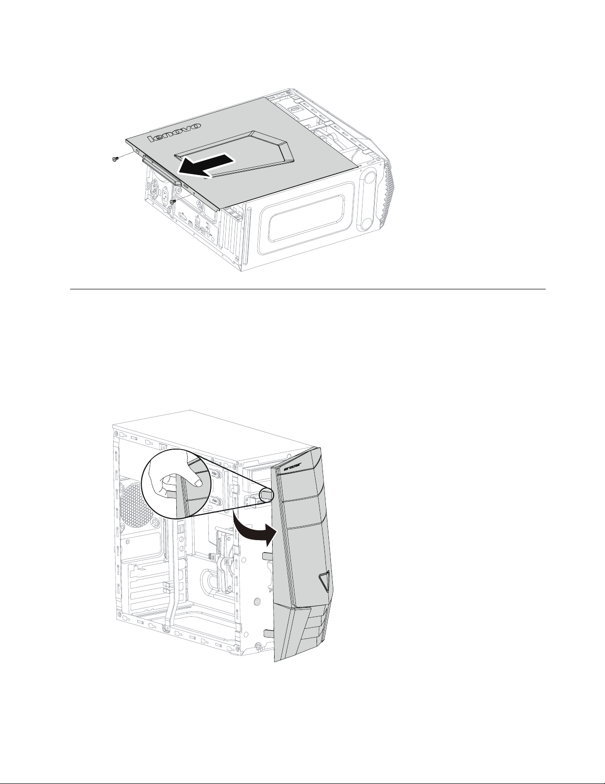
Step5.Slidethecomputercoverouttoremoveit.
Removingthefrontbezel
Note:Forthisprocedure,ithelpstolaythecomputerflat.
Toremovethefrontbezel:
Step1.Removethecomputercover.Referto“Removingthecomputercover”.
Step2.Removethefrontbezelbyreleasingthethreeplastictabsinsidethechassisandpullingthebezel
outasshown.
Step3.T oreattachthebezel,aligntheplastictabsonthebottomofthebezelwiththecorrespondingholes
inthechassis,andthensnapitintoposition.
Chapter8.Replacinghardware27
Page 34
Replacingamemorymodule
Note:Forthisprocedure,ithelpstolaythecomputerflat.
Toreplaceamemorymodule:
Step1.Removethecomputercover.Referto“Removingthecomputercover”.
Step2.Locatethememorymoduleconnectors.Referto“Locatingcomponents”.
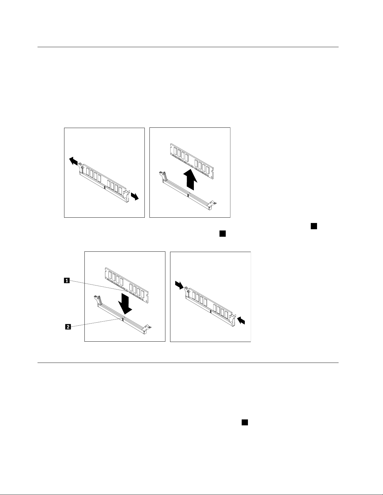
Step3.Removethememorymoduletobereplacedbyopeningtheretainingclipsasshown.
Step4.Positionthenewmemorymoduleoverthememoryconnector.Makesurethatthenotch1onthe
memorymodulealignscorrectlywiththeconnectorkey
modulestraightdownintotheconnectoruntiltheretainingclipsclose.
2onthesystemboard.Pushthememory
Step5.Reattachthecomputercover.
Replacingaharddiskdrive
Note:Forthisprocedure,ithelpstolaythecomputerflat.
Toreplaceaharddiskdrive:
Step1.Removethecomputercover.Referto“Removingthecomputercover”.
Step2.Disconnectthedataandpowercablesfromtheharddiskdrive.1
28LenovoErazerX310HardwareMaintenanceManual
Page 35
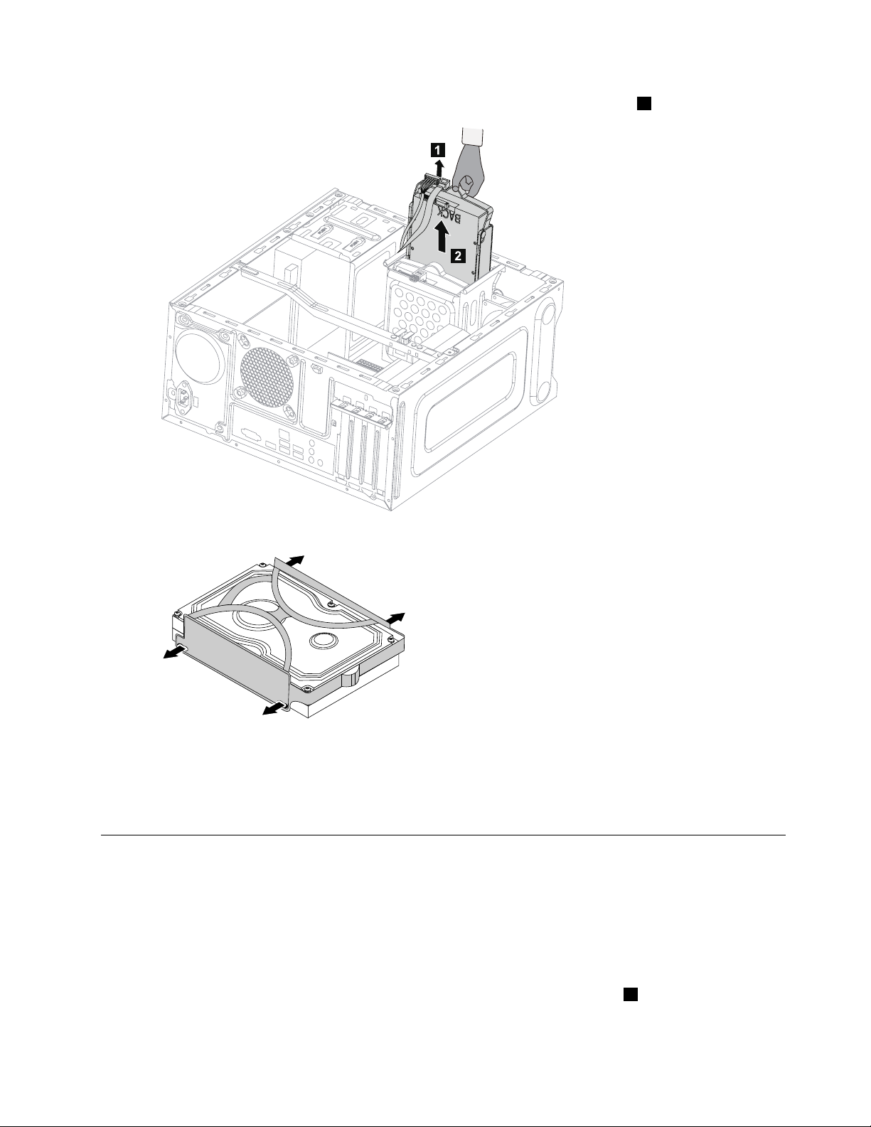
Step3.Liftuptheplastichandleandslidetheharddiskdriveoutofthedrivebay.2
1
2
Step4.Removetheharddiskdrivefromtheplasticbracketasshown.
Step5.Lineupthenewharddiskdrivewiththeplasticbracketandsnapitintoposition.
Step6.Slidethenewharddiskdriveintothedrivebayandslidethedrivebayintoplace.
Step7.Connectthepowerandsignalcablestothenewharddiskdrive.
Step8.Reattachthecomputercover.
Replacinganopticaldrive
Note:Forthisprocedure,ithelpstolaythecomputerflat,stablesurface.
Toreplaceanopticaldrive:
Step1.Removethecomputercover.Referto“Removingthecomputercover”.
Step2.Removethefrontbezel.Referto“Removingthefrontbezel”.
Step3.Disconnectthedataandpowercablesfromtherearoftheopticaldrive.1
Chapter8.Replacinghardware29
Page 36
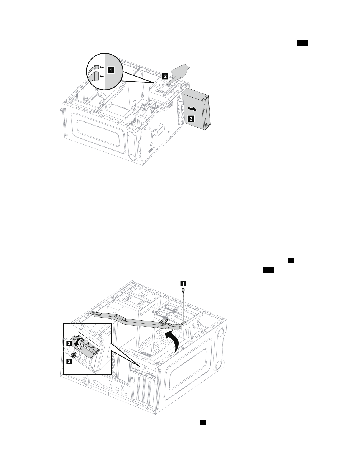
Step4.Pressthereleasebuttonandpushtheopticaldrivestraightoutofthefrontofthechassis.23
1
2
3
2
3
1
Step5.Slidethenewopticaldriveintothebayfromthefrontuntilitsnapsintoposition.
Step6.Connectthedataandpowercablestothenewdiskdrive.
Step7.Reattachthefrontbezelandcomputercover.
Replacingagraphicscard
Note:Forthisprocedure,ithelpstolaythecomputeronaflat,stablesurface.
Toreplaceagraphicscard:
Step1.Removethecomputercover.Referto“Removingthecomputercover”.
Step2.Removethescrewthatsecuresthegraphicscardfixingbracketandliftthebracketup.1
Step3.Removethescrewthatsecuresthegraphicslatchtothechassisandopenit.23
Step4.Disconnectthepowercablesfromthegraphicscard.1
30LenovoErazerX310HardwareMaintenanceManual
Page 37
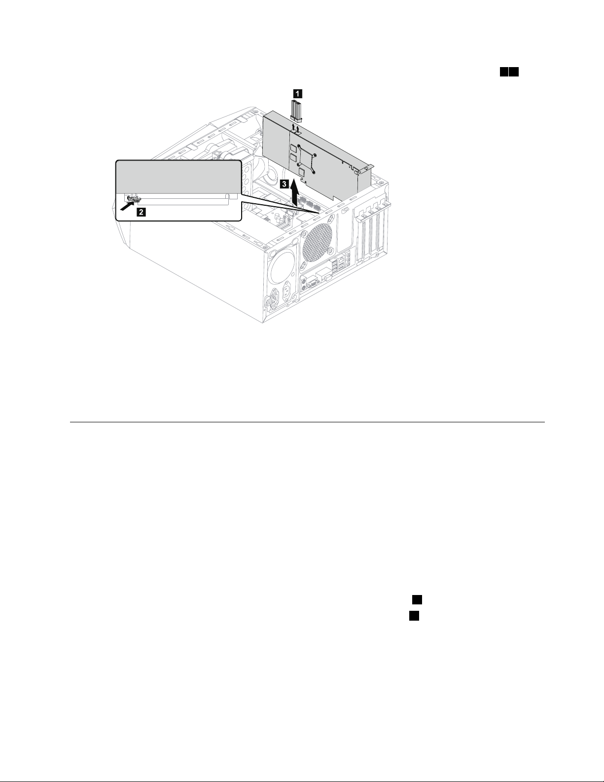
Step5.Pushthepintounlockthegraphicscard,andthenliftupthegraphicscardtoremoveit.23
3
2
1
Step6.T oinstallthenewgraphicscard:
a.Attachthenewgraphicscardtothesameadapterconnector.
b.Connectthepowercablestothenewgraphicscard.
c.Turnthegraphicscardlatchtotheclosedpositionandsecureitwiththescrew.
Step7.Reattachthegraphicscardfixingbracketandcomputercover.
ReplacingthePowersupply
Note:Forthisprocedure,ithelpstolaythecomputerflat.
ToreplacethePowersupply:
Step1.Removeanymedia(disks,CDs,DVDs,ormemorycards)fromthedrives,shutdowntheoperating
system,andturnoffthecomputerandallattacheddevices.
Step2.Unplugallpowercordsfromelectricaloutlets.
Step3.Disconnectallcablesattachedtothecomputer.Thisincludespowercords,input/output(I/O)
cables,andanyothercablesthatareconnectedtothecomputer.Referto“Leftandrightview”
and“Rearview”forhelpwithlocatingthevariousconnectors.
Step4.Removethecomputercover.Referto“Removingthecomputercover”.
Step5.Disconnectthepowercablesfromtheconnectorsonmotherboard.1
Step6.Removethe4screwsthatsecurethePowersupplytothechassis.2
Chapter8.Replacinghardware31
Page 38
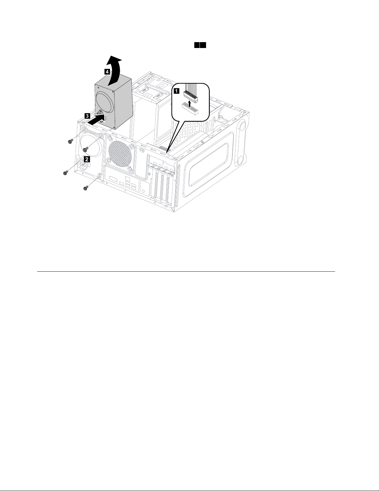
Step7.SlidethenliftthePowersupplyoutofchassis.34
2
Step8.Installthenewpowersupply:
a.Lineuptheholesonthenewpowersupplywithmountingholesontherearofthechassisand
secureittothechassiswiththe4screws.
b.Connectthepowercablestotheconnectorsonthemotherboard.
Step9.Reattachthecomputercover.
Replacingthemicroprocessorfan
Toreplacethemicroprocessorfan:
Step1.Removeanymedia(disks,CDs,DVDs,ormemorycards)fromthedrives,shutdowntheoperating
system,andturnoffthecomputerandallattacheddevices.
Step2.Unplugallpowercordsfromelectricaloutlets.
Step3.Disconnectallcablesattachedtothecomputer.Thisincludespowercords,input/output(I/O)
cables,andanyothercablesthatareconnectedtothecomputer.Referto“Leftandrightview”
and“Rearview”forhelpwithlocatingthevariousconnectors.
Step4.Removethecomputercover.Referto“Removingthecomputercover”.
Step5.Disconnectthefanpowercablefromtheconnectoronthemotherboard.
32LenovoErazerX310HardwareMaintenanceManual
Page 39
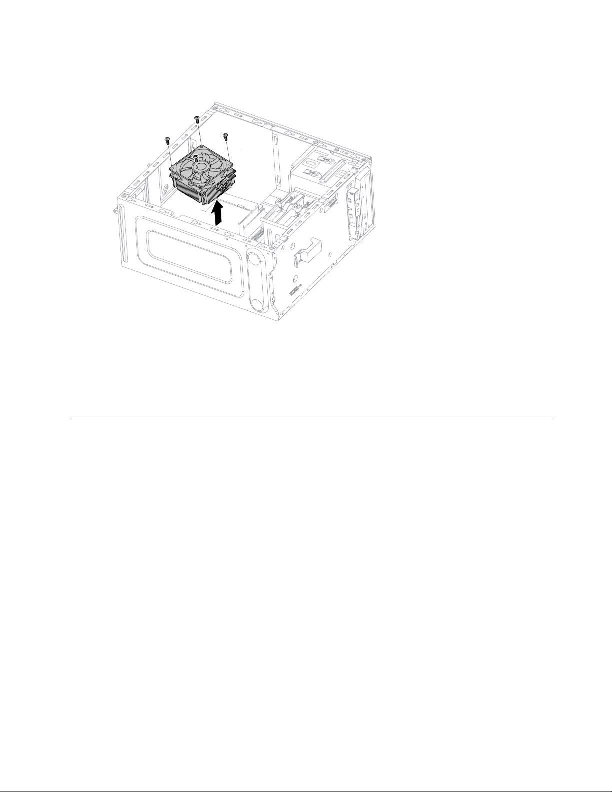
Step6.Removethe4screwsthatsecurethemicroprocessorfantotheheat-sinkandliftupthe
microprocessorfantoremoveit.
Step7.T oinstallthenewmicroprocessorfan:
a.Lineupthenewmicroprocessorfanwiththeheat-sinkandsecureittotheheat-sinkwith
4screws.
b.Connectthemicroprocessorfanpowercabletotheconnectorontheboard.
Step8.Reattachthecomputercover.
Replacingtheheat-sink
Note:Forthisprocedure,ithelpstolaythecomputerflat.
Toreplacetheheat-sink:
Step1.Removeanymedia(disks,CDs,DVDs,ormemorycards)fromthedrives,shutdowntheoperating
system,andturnoffthecomputerandallattacheddevices.
Step2.Unplugallpowercordsfromelectricaloutlets.
Step3.Disconnectallcablesattachedtothecomputer.Thisincludespowercords,input/output(I/O)
cables,andanyothercablesthatareconnectedtothecomputer.Referto“Leftandrightview”
and“Rearview”forhelpwithlocatingthevariousconnectors.
Step4.Removethecomputercover.Referto“Removingthecomputercover”.
Step5.Removethemicroprocessorfan.Referto“Replacingthemicroprocessorfan”.
Step6.Removethe4screwsthatsecuretheheat-sinktothemotherboard.
Chapter8.Replacinghardware33
Page 40
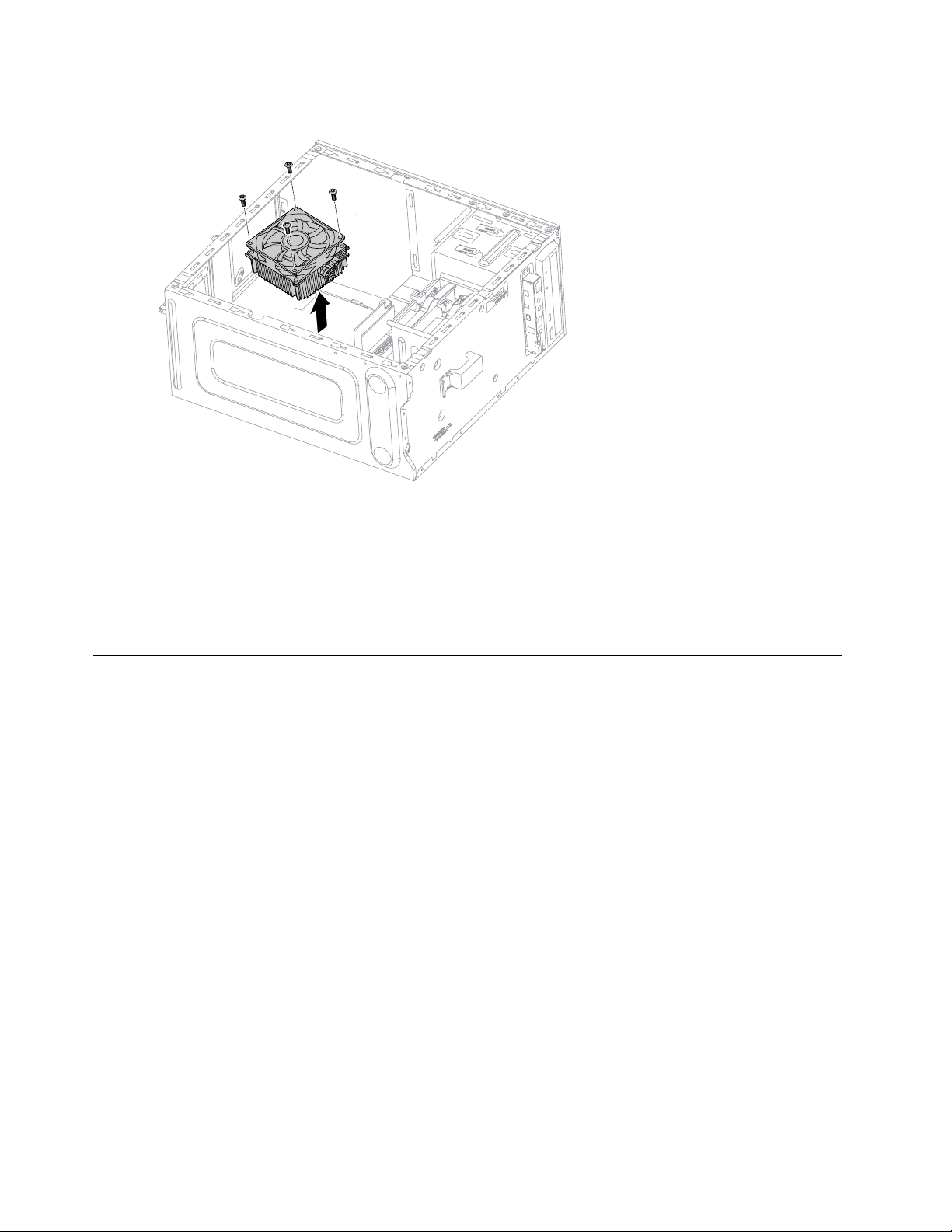
Step7.Liftuptheheat-sinktoremoveit.
Step8.Installthenewheat-sink:
a.Lineupthescrewsonthenewheat-sinkwithmountingholesonthemotherboardandsecure
itwiththe4screws.
b.Reattachthemicroprocessorfantotheheat-sink.
c.Reconnectthemicroprocessorfanpowercabletotheconnectoronthemotherboard.
Step9.Reattachthecomputercover.
ReplacingtheCPU
Note:Forthisprocedure,ithelpstolaythecomputerflat.
ToreplacetheCPU:
Step1.Removeanymedia(disks,CDs,DVDs,ormemorycards)fromthedrives,shutdowntheoperating
system,andturnoffthecomputerandallattacheddevices.
Step2.Unplugallpowercordsfromelectricaloutlets.
Step3.Disconnectallcablesattachedtothecomputer.Thisincludespowercords,input/output(I/O)
cables,andanyothercablesthatareconnectedtothecomputer.Referto“Leftandrightview”
and“Rearview”forhelpwithlocatingthevariousconnectors.
Step4.Removethecomputercover.Referto“Removingthecomputercover”.
Step5.Removethemicroprocessorfan.Referto“Replacingthemicroprocessorfan”.
Step6.Removetheheat-sink.Referto“Replacingtheheat-sink”.
34LenovoErazerX310HardwareMaintenanceManual
Page 41
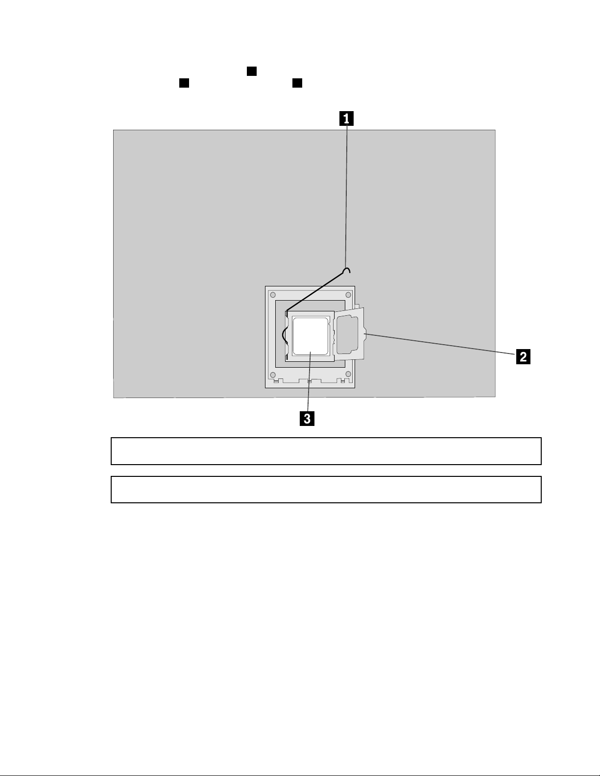
Step7.T oremovethemicroprocessor3fromthesystemboard,pressthenslidethesmallhandleout
tospringitup.
1andopentheretainer.2
Attention:Donottouchthegoldcontactsonthebottomofthemicroprocessor.Whenhandingthe
microprocessor,touchonlythesides.
Note:Donotdropanythingontothemicroprocessorsocketwhileitisexposed.Thesocketpinsmust
bekeptascleanaspossible.
Chapter8.Replacinghardware35
Page 42
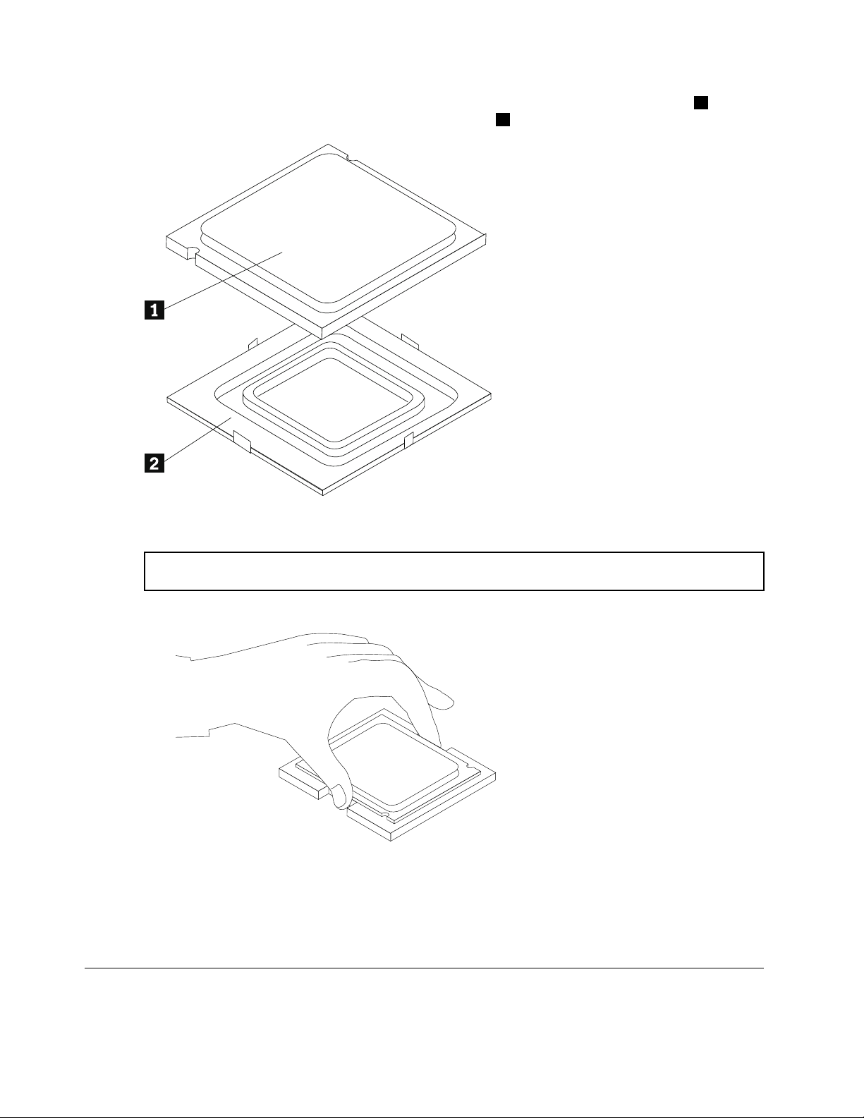
Step8.Holdingthesidesofthemicroprocessorwithyourfingers,removetheprotectivecover1that
protectsthegoldcontactsonthenewmicroprocessor.
2
Step9.Holdingthesidesofthemicroprocessorwithyourfingers,positionthemicroprocessorsothatthe
notchesonthemicroprocessorarealignedwiththetabsinthemicroprocessorsocket.
Important:Toavoiddamagingthemicroprocessorcontacts,keepthemicroprocessorcompletelylevel
whileinstallingitintothesocket.
Step10.Lowerthemicroprocessorstraightdownintoitssocketonthemotherboard.
Step11.Tosecurethemicroprocessorinthesocket,closethemicroprocessorretainerandlockitinto
positionwiththesmallhandle.
Step12.Useathermalgreasesyringetoplace5dropsofgreaseonthetopofthemicroprocessor.Each
dropofgreaseshouldbe0.03ml(3tickmarksonthegreasesyringe).
Step13.Reattachtheheat-sink,microprocessorfan,computercover.
ReplacingtheWi-Ficard
Note:Forthisprocedure,ithelpstolaythecomputerflat.
36LenovoErazerX310HardwareMaintenanceManual
Page 43
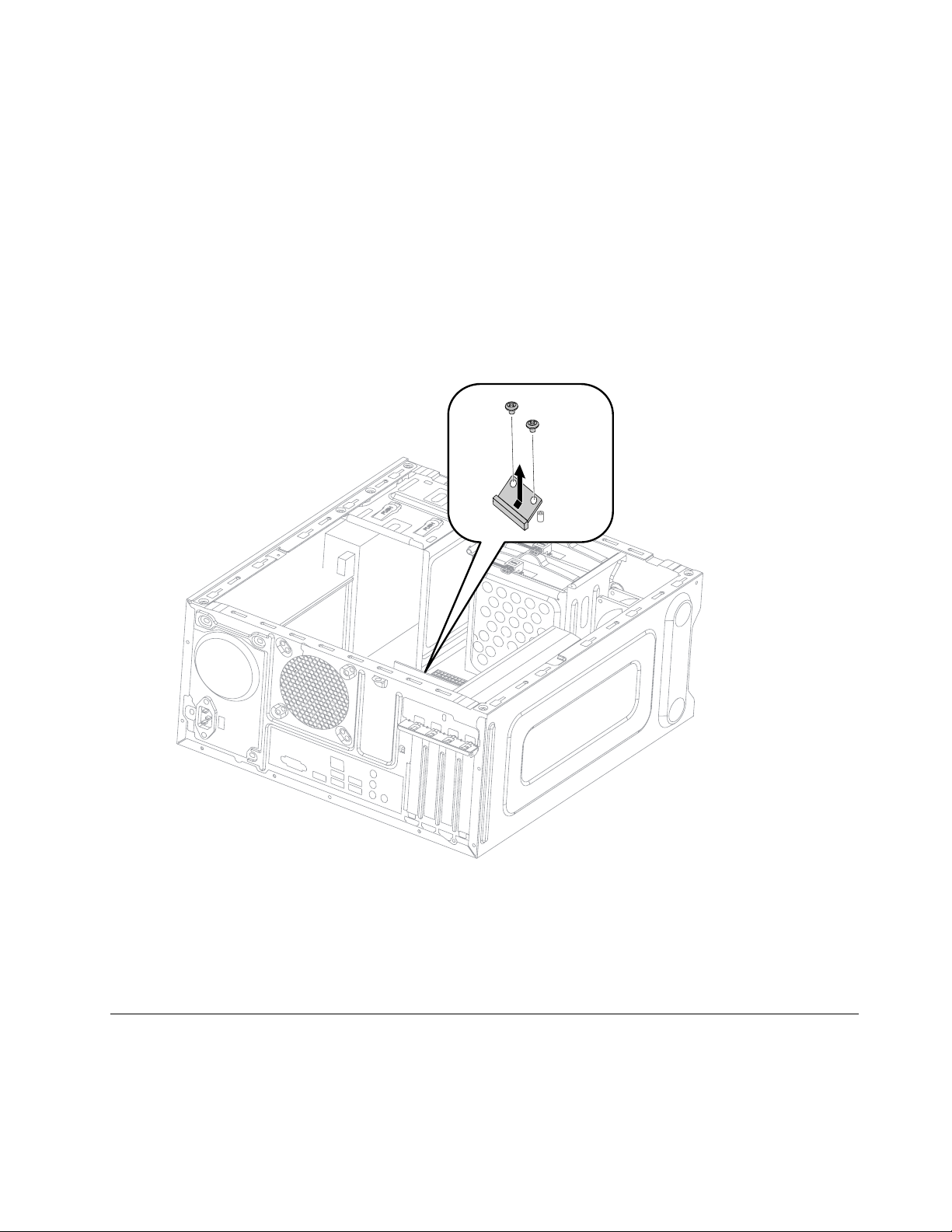
ToreplacetheWi-Ficard:
Step1.Removeanymedia(disks,CDs,DVDs,ormemorycards)fromthedrives,shutdowntheoperating
system,andturnoffthecomputerandallattacheddevices.
Step2.Unplugallpowercordsfromelectricaloutlets.
Step3.Disconnectallcablesattachedtothecomputer.Thisincludespowercords,input/output(I/O)
cables,andanyothercablesthatareconnectedtothecomputer.Referto“Leftandrightview”
and“Rearview”forhelpwithlocatingthevariousconnectors.
Step4.Removethecomputercover.Referto“Removingthecomputercover”.
Step5.Disconnectthe2antennacablesfromtheWi-Ficard.
Step6.Removethe2screwsthatsecuretheWi-Ficardtothemotherboard.
Step7.PulltheWi-Ficardupwardtoremoveitfromthecardport.
Step8.InstallthenewWi-Ficard:
a.LineupthenewWi-Ficard,theninsertitintothesamecardport.
b.SecuretheWi-Ficardtothemotherboardwiththe2screws.
c.Connectthe2antennacablestothenewWi-Ficard.
Step9.Reattachthecomputercover.
Replacingthemotherboard
Note:Forthisprocedure,ithelpstolaythecomputerflat.
Toreplacethemotherboard:
Chapter8.Replacinghardware37
Page 44
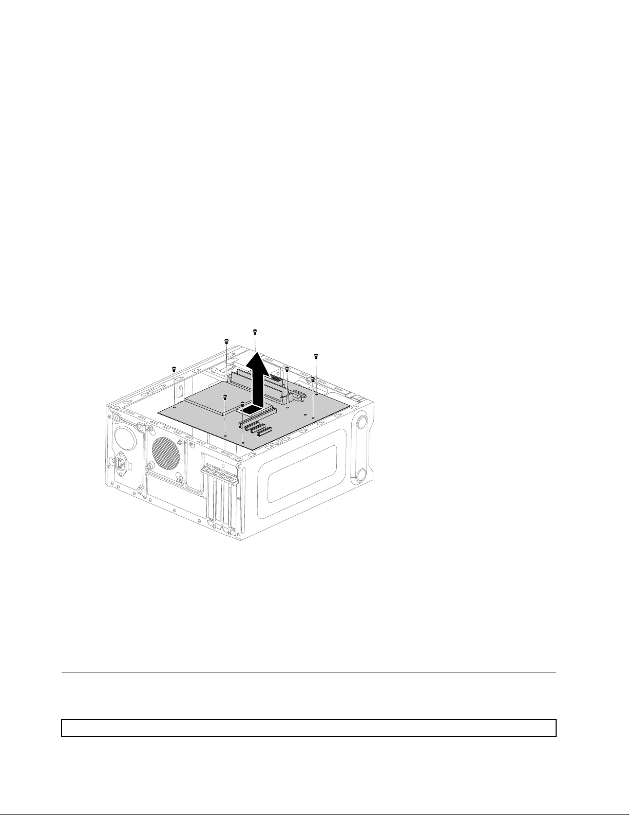
Step1.Removeanymedia(disks,CDs,DVDs,ormemorycards)fromthedrives,shutdowntheoperating
system,andturnoffthecomputerandallattacheddevices.
Step2.Unplugallpowercordsfromelectricaloutlets.
Step3.Disconnectallcablesattachedtothecomputer.Thisincludespowercords,input/output(I/O)
cables,andanyothercablesthatareconnectedtothecomputer.Referto“Leftandrightview”
and“Rearview”forhelpwithlocatingthevariousconnectors.
Step4.Removethecomputercover.Referto“Removingthecomputercover”.
Step5.Removethememorymodule.Referto“Replacingamemorymodule”.
Step6.Removethemicroprocessorfan.Referto“Replacingthemicroprocessorfan”.
Step7.Removetheheat-sink.Referto“Replacingtheheat-sink”.
Step8.Removethegraphiccard.Referto“Replacingagraphiccard”.
Step9.RemovetheWi-Ficard.Referto“ReplacingtheWi-Ficard”.
Step10.RemovetheCPU.Referto“ReplacingtheCPU”.
Step11.Disconnecttheallcablesfromtheconnectorsonmotherboard.
Step12.Removethe8screwsthatsecurethemotherboardtothechassis.
Step13.Slidethenliftthemotherboardoutofthechassistoremoveit.
Step14.Installthenewmotherboard:
a.Lineuptheholesonthenewmotherboardwithmountingholesonthechassisandsecure
itwithscrews.
b.Reattachthememorymodule,Wi-Ficard,CPU,andtheheat-sinktothenewmotherboard.
c.Connecttheallcablestothenewmotherboard.
d.Attachthegraphiccardtothenewmotherboard.
Step15.Reattachthecomputercover.
FRUlists
Thischapterliststheinformationonthefieldreplaceableunits(FRUs).
Attention:BesuretoreadandunderstandallthesafetyinformationbeforereplacinganyFRUs.
38LenovoErazerX310HardwareMaintenanceManual
Page 45

Notes:FRUsthathavea1or2intheCRUcolumnareCustomerReplaceableUnits(CRUs).
•1–identifiespartsthatarefairlysimpletoreplace,requiringfewornotools.
•2–identifiespartsthatareslightlymoredifficulttoreplace.
•N-identifiespartsthatarenottobereplacedbythecustomer .
Description
Haswell&Haswell-Refresh
II7-47703.4/1600/8/115084CPU
II5-45703.2/1600/6/115084CPU
II5-44403.1/1600/4C/6M/115084CPU
II3-43303.5/1600/2C/4M/115054CPU
II3-41303.4/1600/2C/3M/115054CPU
II7-47903.6/1600/4C/8M/115084WCPU
II5-45903.3/1600/4C/6M/115084WCPU
II5-44603.2/1600/4C/6M/115084WCPU
II3-41503.5/1600/2C/3M/115054WCPU
MB
MB85MPrefresh
90003258forMBFRUNOK
90003259forMBFRUW8S
90003260forMBFRUW8P
Thermal
TSLCEL3102836A6Intel65/95WCooler
DWPHIntel65/95WCooler
FoxconnPKP734G01K12Zintel65Coolerkit
AVCZ8UL06S012Intel65/95WCooler
LX460mmfeelingWenXian's6pins®
GS460mmsensorcablew_6pin®
FOXPV902512PSPF0JG29225Sysfan(R)
AVCDS09225R12HP1839225Sysfan(R)
FrontFan
AVCDS09225R12HP251Frontfan
RAM
M378B5173DB0-CK04GBD3-1600RAM-HF
HMT451U6BFR8C-PB4GBD3-1600RAM-HF
MT8JTF51264AZ-1G6E14GBD3-1600RAM
Mic_RD9QBJ4GBD3L -1600M2RAM
Mic_SD9QBJ4GBD3-1600M2RAM
M378B1G73DB0-CK08GBD3-1600RAM-HF
HMT41GU6BFR8C-PB8GBD3-1600RAM-HF
LenovoP/NCRUID
1100783N
1100786N
1100949N
1100929N
1100930N
1101104N
1101106N
1101107N
1101088N
SB20F76086
N
12751N
12752N
12753N
31045550N
31506282N
31045548N
31045549N
31034561N
31045784N
31039640N
31039310N
31500949N
11009442
11009882
11009552
11008072
11006822
11009452
11009892
Chapter8.Replacinghardware39
Page 46

MT16JTF1G64AZ-1G6E18GBD3-1600RAM
Mic_RD9QBJ8GBD3L -1600RAM-HF
HDD
WDXL500AWD5000AAKX-08U6AA0500GHDD-LH
SGTPharaoh4KST500DM002500GHDD-LH
TSBMars4K500GDT01ACA050-LH
3.5inchSATA6G7.2KGrenadaBP1.51TB
WDXL1000BWD10EZEX-08M2NA01TBHDD162006132
TSBMars4K1TBDT01ACA100-LH
3.5inchSATA6G7.2KGrenadaBP1.52TB
SGTGrenadaBPST2000DM0012TBHDD-LH
TSBMars4K2TBDT01ACA200-LH
SSHD
SeagateGrenada1TBST1000DX001SSHD-LH
SeagateGrenada2TBST2000DX001SSHD-LH
SSD
SSMZ7TE256HMHP256G2.5"SSD
Lite-onLCS-256M6S256GBSATASSD
ODD
HLDSDH50NHHSA TADVD-ROM-LH
TSST16XSH-116BBSAT ABlackDVDROM-LH
PLDS16XDH-16D7SHHHSA T ADVDROM-LH
TSST16XSH-116CBSA T ADVDROM-LH
PSNSW430HHSA TADVDROM-LH
PLDS16XDH-16AESHSA TABlackDVDRW-LH(LSOPU)
TSSTSH-216DBHHSATARamboODD-LH
Panasonic16XSW830HHSATADVDRW-LH
HLDSGHB0NHHSA TARambo-LH
HLDSBH40NBlu-rayRecorder-LH(BE)
ODDDoorcover
HongHaiLX319ChassisODDMetalBaffle(R)
Gfx
Bitland@GeforceGTX760@2G/A/2D/DP/HGraphics
JTLX-319K4ChassisUniversalGraphicsbracket
MSI@GeforceGTX750@2G/A/2D/mHDMIGraphics
MSI@GeforceGTX745@2G/A/DB/HGraphics
MSI@GeforceGT720@2G/A/DB/HGraphics
Bitland@GeforceGT705@1G/A/DB/HGraphics
11006692
11010112
162005442
162001782
162005122
162005282
162005132
162005292
162002942
162005142
162005342
162005352
162006052
162004882
252106492
252137192
252058002
252162272
252144982
252130612
252137202
252138852
252144702
252106512
31046268N
112022982
315007672
112028042
112028022
112027462
112027422
MSI@GeforceGT705@1G/A/DB/HGraphics
40LenovoErazerX310HardwareMaintenanceManual
112027432
Page 47

MGE4pinto6pinpowercable150mm
Bitland@R5235@1G/A/DB/HGraphics
MSI@R5235@1G/A/DB/HGraphics
Bitland@R5235@2G/A/DB/HGraphics
Bitland@R7240@2G/A/DB/HGraphics
315040752
112024032
112024042
112027482
112024072
VIDEO_CARDM@R9260@2G/A/DB/D/DP/HSV10G52022
VIDEO_CARDB@GeforceGTX750Ti@2G/A/DBDHSV10G52021
MSI@R9255@2G/A/D/DP/HGraphics
PSU
HuntkeyHK280-22GPS5PS3180WPSU
AcbelAPI6PC06-EL3GPS3180WPSU
LiteonPS-5181-8VS2-ROHSPS3180WPSU
NewcableLCPS3180WFSP180-50PSAPSU®
ACBELPC8061-EL2GWW180WPSU
LITEONPS-5181-09VSWW180WPSU
ACBELPC6001-EL9GA TX280WPSU
LITEONPS-5281-7VR5ATX280WPSU
HKHK380-12GPS2(S7)A TX280WPSU
ACBELPC9008-EL1GA TX280WESPSU
LITEONPS-5281-02VAATX280WESPSU
FSPFSP280-50EPAATX280WESPSU
ACBELPC7033-EL2G450WPSU
Wifi
LiteonWB3351x1BGN+BT4.0HMCWLAN
CbtRTL8723BE1x1BGN+BTHMCWLAN
CBTRTL8821AE1x1acBTcomboHMC
LTNRTL8821AE1x1ac+BT4.0ComboHMC
LSX310FrontAntenna
LSX310RearAntenna
JTM2X3DedicatedScrew
112025062
36200083N
36200084N
36200085N
36200438N
36200488N
36200489N
36200498N
36200499N
36200500N
36200501N
36200502N
36200503N
36200597N
20200437N
20200440N
20200571N
11202485N
31507037N
31507038N
31501076N
JTWiFiAntennacover31501130N
CardReader
TaisolGL827S7in1L_Single_CR
BitlandRTS51797in1L_Single_CR
USB/AudioCable
LSUSB3.0F_IOcable_U530A650_36PIN
CLUSB3.0F_IOcable_U530A650_36PIN
Chassis
JTLX-328BT -23LChassis
11201222N
11201223N
31507033N
31507034N
30500516N
JT328BT-23LChassis5C80G59224
2
2
N
Chapter8.Replacinghardware41
Page 48

JT328BT -23LChassisF/Bezel5B30G59221
JT328BT -23LHDDBracket
JT328BT -23LUSBUSB&CRBracket5B40G59223
JT328BT -23LWlanAntennaCover5CB0G59219
JTB85MBrearIOshielding
KaveriA78rearIObaffleforX3
JTX3LEDCable_630mm
MGEX3LEDCable_630mm
JTLX-328BTChassis
JTB85MBrearIOshielding
HDD/ODDSATAcable
GS2H300mmSATAcalbeLatch®
LX2H300mmSATAcalbeLatch®
GS2H300mmSATAcalbeLatch®
LX2H300mmSATAcalbeLatch®
LX370mmSATADataLine(R)
GuanXu370mmSATADataLine(R)
CL2H420mmSATAcalbeLatch®
MGE2H420mmSATAcalbeLatch(R)
LX2H420mmSATAcalbeLatch®
LSDVIDVIcable1.8m
LX200mmHDMItoDVIDScable®
LX130mmDVI-to-VGAcord®
PA T ATOSA TACABLE
GS2H100mm4pinSATAcableLatch®
LX2H100mm4pin-SATAcableLatch®
RubberCover
JTVGAplasticcover
JTHDMIrubbercover31049017N
LI2323swA/TPV/A/R/WW65A7-HB1
Speaker
LenovospeakerM0620Black250137421
TouchPad
ChiconyTGR12262.4GtouchpadBLKfinal
KB/MOUSE
SunrexEKB-10Y A(US)B-SilkUSBKB-LVT8
PrimaxKB4721(US)B-SilkUSBKB-LVT8
ChiconyKU-1153(US)B-SilkUSBKB-LVT8
SunrexEKB-10Y A(TW)B-SilkUSBKB-LVT8
SunrexEKB-10Y A(TH)B-SilkUSBKB-LVT8
5B40G59220
31503330N
31506693N
31507035N
31507036N
30500516N
31503330N
31024767N
31024785N
31024767N
31024785N
31034778N
31034820N
31506478N
31506479N
31024760N
31501245N
31041295N
31024556N
31024761N
31024766N
31049015N
18201611N
252129691
252091111
252091121
252091131
252091141
252091151
N
N
N
N
42LenovoErazerX310HardwareMaintenanceManual
Page 49

SunrexEKB-10Y A(CZ-SL)B-SUSBKB-LVT8
SunrexEKB-10Y A(IN)B-SilkUSBKB-LVT8
SunrexEKB-10Y A(RU)B-SilkUSBKB-LVT8
SunrexEKB-10Y A(UK)B-SilkUSBKB-LVT8
SunrexEKB-10Y A(Nordic)B-SUSBKB-LVT8
SunrexEKB-10Y A(LA)B-SilkUSBKB-LVT8
SunrexEKB-10Y A(AR)B-SilkUSBKB-LVT8
SunrexEKB-10Y A(SW)B-SilkUSBKB-LVT8
SunrexEKB-10Y A(GE)B-SilkUSBKB-LVT8
SunrexEKB-10Y A(TR)B-SilkUSBKB-LVT8
SunrexEKB-10Y A(SP)B-SilkUSBKB-LVT8
SunrexEKB-10Y A(SL)B-SilkUSBKB-LVT8
SunrexEKB-10Y A(IT)B-SilkUSBKB-LVT8
SunrexEKB-10Y A(HB)B-SilkUSBKB-LVT8
SunrexEKB-10Y A(FR)B-SilkUSBKB-LVT8
SunrexEKB-10Y A(GK)B-SilkUSBKB-LVT8
SunrexEKB-10Y A(HG)B-SilkUSBKB-LVT8
SunrexEKB-10Y A(BG)B-SilkUSBKB-LVT8
SunrexEKB-10Y A(HR)B-SilkUSBKB-LVT8
SunrexEKB-10Y A(JP)B-SilkUSBKB-LVT8
SunrexEKB-10Y A(EN-FR)B-SUSBKB-LVT8
SunrexEKB-10Y A(PT)B-SilkUSBKB-LVT8
SunrexEKB-10Y A(BE-EN)B-SUSBKB-LVT8
SunrexEKB-10Y A(DU)B-SUSBKB-LVT8
LiteonLXH-SM-8825B-SilkMouse
SunrexLXH-EMS-10ZAB-SilkMouse
LenovolasermouseM6811(B)
PrimaxM300USBgesturemouseBLK
LiteonSK-8861(US)2.4GKB-Black8
LiteonSK-8861(US-MY)2.4GKB-Black8
LiteonSK-8861(TW)2.4GKB-Black8
LiteonSK-8861(TH)2.4GKB-Black8
LiteonSK-8861(CS-SK)2.4GKB-Black8
LiteonSK-8861(US-IN)2.4GKB-Black8
LiteonSK-8861(RU)2.4GKB-Black8
LiteonSK-8861(GB)2.4GKB-Black8
LiteonSK-8861(Nordic)2.4GKB-Black8
LiteonSK-8861(LA)2.4GKB-Black8
LiteonSK-8861(LA-AR)2.4GKB-Black8
LiteonSK-8861(SA)2.4GKB-Black8
252091161
252091171
252091181
252091191
252091201
252091211
252091221
252091231
252091241
252091251
252091261
252091271
252091281
252091291
252091301
252091311
252091321
252091331
252091341
252091351
252091361
252091371
252091381
252091391
252005281
252005301
250137971
252138761
252091751
252091761
252091771
252091781
252091791
252091801
252091811
252091821
252091831
252091841
252091851
252091861
Chapter8.Replacinghardware43
Page 50

LiteonSK-8861(CH)2.4GKB-Black8
LiteonSK-8861(DE)2.4GKB-Black8
LiteonSK-8861(TR)2.4GKB-Black8
LiteonSK-8861(ES)2.4GKB-Black8
LiteonSK-8861(SL)2.4GKB-Black8
LiteonSK-8861(IT)2.4GKB-Black8
LiteonSK-8861(IL)2.4GKB-Black8
LiteonSK-8861(FR)2.4GKB-Black8
LiteonSK-8861(GR)2.4GKB-Black8
LiteonSK-8861(HU)2.4GKB-Black8
LiteonSK-8861(BG)2.4GKB-Black8
LiteonSK-8861(KR)2.4GKB-Black8
LiteonSK-8861(JP)2.4GKB-Black8
LiteonSK-8861(EN-FR)2.4GKB-Black8
LiteonSK-8861(PT)2.4GKB-Black8
LiteonSK-8861(BE-EN)2.4GKB-Black8
LiteonSK-8861(DU)2.4GKB-Black8
LiteonSM-8861(WW)MouseBlack
LiteonSM-8861Mouse(NoBattery)Black
LiteonSM-8861(JP)Mouse-Black
LiteonSM-8861Mouse(MY)Black
GamingKB&Mouse
ChiconyKU-0603(US)USBgamingKB
ChiconyKU-0603(IN)USBgamingKB
NewmenMS-172USBgamingmouseblack
252091871
252091881
252091891
252091901
252091911
252091921
252091931
252091941
252091951
252091961
252091971
252091981
252091991
252092001
252092011
252092021
252092031
252034641
252034651
252057731
252034661
252102031
252162481
252137911
44LenovoErazerX310HardwareMaintenanceManual
Page 51

Chapter9.Generalinformation
Thischapterprovidesgeneralinformationthatappliestoallmachinetypessupportedbythispublication.
AdditionalServiceInformation
Thischapterprovidesadditionalinformationthattheservicerepresentativemightfindhelpful.
Powermanagement
Powermanagementreducesthepowerconsumptionofcertaincomponentsofthecomputersuchasthe
systempowersupply,processor,harddiskdrives,andsomemonitors.
Advancedconfigurationandpowerinterface(ACPI)BIOS
AsthiscomputerhasanACPIBIOSsystem,theoperatingsystemisallowedtocontrolthepower
managementfeaturesofthecomputerandthesettingsforAdvancedPowerManagement(APM)BIOSmode
isignored.NotalloperatingsystemssupportACPIBIOSmode.
AutomaticPower-Onfeatures
TheAutomaticPower-OnfeatureswithinthePowerManagementmenuallowyoutoenableanddisable
featuresthatturnonthecomputerautomatically.
•WakeUponAlarm:Y oucanspecifyadateandtimeatwhichthecomputerwillbeturnedonautomatically.
Thiscanbeeitherasingleevent,adailyeventoraweeklyevent.
•WakeUponLAN:ThisfeatureallowsLANadaptercardtowaketheSystem.
©CopyrightLenovo2014
45
 Loading...