

Page 1

ThinkSystem SR860
Setup Guide
Machine Type: 7X69 and 7X70
Page 2

Note
Before using this information and the product it supports, be sure to read and understand the safety
information and the safety instructions, which are available at:
http://thinksystem.lenovofiles.com/help/topic/safety_documentation/pdf_files.html
In addition, be sure that you are familiar with the terms and conditions of the Lenovo warranty for your server,
which can be found at:
http://datacentersupport.lenovo.com/warrantylookup
First Edition (November 2017)
© Copyright Lenovo 2017.
LIMITED AND RESTRICTED RIGHTS NOTICE: If data or software is delivered pursuant to a General Services
Administration “GSA” contract, use, reproduction, or disclosure is subject to restrictions set forth in Contract No.
GS-35F-05925
Page 3

Contents
Safety . . . . . . . . . . . . . . . . . . iii
Safety inspection checklist . . . . . . . . . . . iv
Chapter 1. Introduction . . . . . . . . . 1
Server package contents . . . . . . . . . . . . 1
Features. . . . . . . . . . . . . . . . . . . 2
Specifications . . . . . . . . . . . . . . . . 3
Management options. . . . . . . . . . . . . . 7
Chapter 2. Server components . . . . 15
Front view . . . . . . . . . . . . . . . . . 16
Front operator panel . . . . . . . . . . . 18
Front operator panel with LCD display . . . . 19
Rear view . . . . . . . . . . . . . . . . . 23
Optional processor and memory expansion tray . . 27
PCIe riser cards. . . . . . . . . . . . . . . 30
2.5-inch drive backplanes . . . . . . . . . . . 31
RAID adapters . . . . . . . . . . . . . . . 32
Internal cable routing. . . . . . . . . . . . . 33
Guideline for cable routing for 2.5-inch
drives . . . . . . . . . . . . . . . . . 33
Cable routing for 2.5-inch drives to one
backplane . . . . . . . . . . . . . . . 36
Cable routing for 2.5-inch drives to two
backplanes. . . . . . . . . . . . . . . 39
Parts list. . . . . . . . . . . . . . . . . . 52
Power cords . . . . . . . . . . . . . . 56
Chapter 3. Server hardware setup . . 57
Server setup checklist . . . . . . . . . . . . 57
Installation Guidelines . . . . . . . . . . . . 58
System reliability guidelines . . . . . . . . 59
Handling static-sensitive devices . . . . . . 59
Install server hardware options . . . . . . . . . 60
Remove the security bezel . . . . . . . . . 60
Remove the top cover . . . . . . . . . . 61
Remove a 4U PCIe riser assembly. . . . . . 63
Remove the PCIe expansion tray . . . . . . 64
Remove the chassis air baffle . . . . . . . 65
Remove the system board air baffle and the
power interposer . . . . . . . . . . . . 66
Remove the processor and memory
expansion tray . . . . . . . . . . . . . 67
Remove the fan cage assembly . . . . . . . 69
Install a processor-heat-sink module. . . . . 71
Install a memory module . . . . . . . . . 74
Install a drive backplane. . . . . . . . . . 75
Install a 2.5-inch hot-swap drive . . . . . . 77
Install the fan cage assembly . . . . . . . . 79
Install the system board air baffle and the
power interposer . . . . . . . . . . . . 80
Install the processor and memory expansion
tray . . . . . . . . . . . . . . . . . 81
Install the PCIe riser card assembly . . . . . 84
Install the LOM adapter . . . . . . . . . . 88
How to adjust the position of the retainer on
the M.2 backplane . . . . . . . . . . . . 89
Install an M.2 drive in the M.2 backplane . . . 90
Install the M.2 backplane . . . . . . . . . 91
Install the chassis air baffle . . . . . . . . 93
Install the PCIe expansion tray . . . . . . . 93
Install a 4U PCIe riser assembly. . . . . . . 95
Install the top cover . . . . . . . . . . . 97
Install the security bezel . . . . . . . . . . 99
Install the server in a rack . . . . . . . . . . . 100
Cable the server . . . . . . . . . . . . . . 100
Power on the server . . . . . . . . . . . . . 100
Validate server setup. . . . . . . . . . . . . 100
Power off the server . . . . . . . . . . . . . 101
Chapter 4. System configuration . . . 103
Set the network connection for the Lenovo XClarity
Controller . . . . . . . . . . . . . . . . . 103
Set front USB port for Lenovo XClarity Controller
connection. . . . . . . . . . . . . . . . . 103
Update the firmware . . . . . . . . . . . . . 104
Configure the firmware . . . . . . . . . . . . 107
Memory configuration . . . . . . . . . . . . 108
RAID configuration . . . . . . . . . . . . . 108
Install the operating system . . . . . . . . . . 109
Back up the server configuration . . . . . . . . 109
Chapter 5. Resolving installation
issues . . . . . . . . . . . . . . . . . 111
Appendix A. Getting help and
technical assistance . . . . . . . . . . 115
Before you call . . . . . . . . . . . . . . . 115
Collecting service data . . . . . . . . . . . . 116
Contacting Support . . . . . . . . . . . . . 117
Index . . . . . . . . . . . . . . . . . . 119
© Copyright Lenovo 2017 i
Page 4

ii ThinkSystem SR860 Setup Guide
Page 5
Safety
Before installing this product, read the Safety Information.
Antes de instalar este produto, leia as Informações de Segurança.
Læs sikkerhedsforskrifterne, før du installerer dette produkt.
Lees voordat u dit product installeert eerst de veiligheidsvoorschriften.
Ennen kuin asennat tämän tuotteen, lue turvaohjeet kohdasta Safety Information.
Avant d'installer ce produit, lisez les consignes de sécurité.
Vor der Installation dieses Produkts die Sicherheitshinweise lesen.
Prima di installare questo prodotto, leggere le Informazioni sulla Sicurezza.
Les sikkerhetsinformasjonen (Safety Information) før du installerer dette produktet.
© Copyright Lenovo 2017 iii
Page 6
Antes de instalar este produto, leia as Informações sobre Segurança.
Antes de instalar este producto, lea la información de seguridad.
Läs säkerhetsinformationen innan du installerar den här produkten.
Safety inspection checklist
Use the information in this section to identify potentially unsafe conditions with your server. As each machine
was designed and built, required safety items were installed to protect users and service technicians from
injury.
Important: Electrical grounding of the server is required for operator safety and correct system function.
Proper grounding of the electrical outlet can be verified by a certified electrician.
Caution: This equipment must be installed by trained service personnel, as defined by the NEC and IEC
60950-1, Second Edition, the standard for Safety of Information Technology Equipment. Lenovo assumes
you are qualified in the servicing of equipment and trained in recognizing hazards in products with hazardous
energy levels.
Make sure all power cords are disconnected from the system when reading the following step in
this manual: “Turn off the server and peripheral devices and disconnect the power cords and all
external cables.”
Use the following checklist to verify that there are no potentially unsafe conditions:
1. Make sure that the power is off and the power cord is disconnected.
2. Check the power cord.
• Make sure that the third-wire ground connector is in good condition. Use a meter to measure thirdwire ground continuity for 0.1 ohm or less between the external ground pin and the frame ground.
iv
ThinkSystem SR860 Setup Guide
Page 7

• Make sure that the power cord is the correct type.
To view the power cords that are available for the server:
a. Go to:
http://lesc.lenovo.com
b. In the Customize a Model pane:
1) Click Select Options/Parts for a Model.
2) Enter the machine type and model for your server.
c. Click the Power tab to see all line cords.
• Make sure that the insulation is not frayed or worn.
3. Check for any obvious non-Lenovo alterations. Use good judgment as to the safety of any non-Lenovo
alterations.
4. Check inside the server for any obvious unsafe conditions, such as metal filings, contamination, water or
other liquid, or signs of fire or smoke damage.
5. Check for worn, frayed, or pinched cables.
6. Make sure that the power-supply cover fasteners (screws or rivets) have not been removed or tampered
with.
© Copyright Lenovo 2017 v
Page 8

vi ThinkSystem SR860 Setup Guide
Page 9
Chapter 1. Introduction
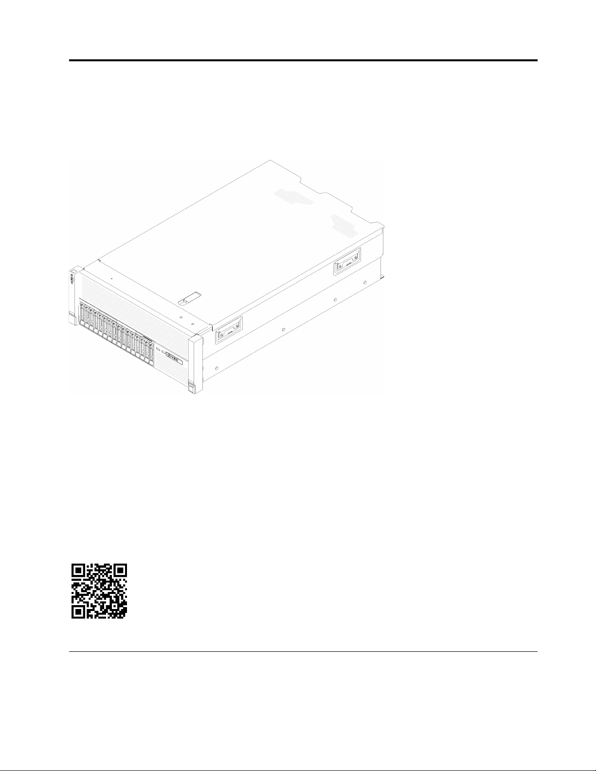
The ThinkSystem SR860 is a 4U rack server designed for high-volume network transaction processing. This
high-performance, multi-core server is ideally suited for networking environments that require superior
processor performance, input/output (I/O) flexibility, and high manageability.
Figure 1. ThinkSystem SR860
The server comes with a limited warranty. For details about the warranty, see:
https://datacentersupport.lenovo.com/us/en/documents/ht100742
For details about your specific warranty, see:
http://datacentersupport.lenovo.com/warrantylookup
In addition, the system service label on the top cover of the server provides a QR code for mobile access to
service information. You can scan the QR code with a mobile device for quick access to additional
information including parts installation, replacement, and error codes.
Following illustration is the QR code:
Figure 2. QR code
Server package contents
When you receive your server, verify that the shipment contains everything that you expected to receive.
© Copyright Lenovo 2017 1
Page 10

The server package includes the following items:
Note: Some of the items listed are available on select models only.
• Server
• Rail installation kit (optional). Detailed instructions for installing the rail installation kit are provided in the
package with the rail installation kit.
• Material box, including items such as rail installation guide and accessory kit.
Features
Performance, ease of use, reliability, and expansion capabilities were key considerations in the design of the
server. These design features make it possible for you to customize the system hardware to meet your needs
today and provide flexible expansion capabilities for the future.
Your server implements the following features and technologies:
• Features on Demand
If a Features on Demand feature is integrated in the server or in an optional device that is installed in the
server, you can purchase an activation key to activate the feature. For information about Features on
Demand, see:
https://fod.lenovo.com/lkms
• Lenovo XClarity Controller (XCC)
The Lenovo XClarity Controller is the common management controller for Lenovo Lenovo ThinkSystem
server hardware. The Lenovo XClarity Controller consolidates multiple management functions in a single
chip on the server system board.
Some of the features that are unique to the Lenovo XClarity Controller are enhanced performance, higherresolution remote video, and expanded security options. For additional information about the Lenovo
XClarity Controller, see:
http://sysmgt.lenovofiles.com/help/topic/com.lenovo.systems.management.xcc.doc/product_page.html
• UEFI-compliant server firmware
Lenovo Lenovo ThinkSystem firmware is Unified Extensible Firmware Interface (UEFI) 2.5 compliant. UEFI
replaces BIOS and defines a standard interface between the operating system, platform firmware, and
external devices.
Lenovo ThinkSystem servers are capable of booting UEFI-compliant operating systems, BIOS-based
operating systems, and BIOS-based adapters as well as UEFI-compliant adapters.
Note: The server does not support DOS (Disk Operating System).
• Active Memory
The Active Memory feature improves the reliability of memory through memory mirroring. Memory
mirroring mode replicates and stores data on two pairs of DIMMs within two channels simultaneously. If a
failure occurs, the memory controller switches from the primary pair of memory DIMMs to the backup pair
of DIMMs.
• Large system-memory capacity
The server supports synchronous dynamic random-access memory (SDRAM) registered dual inline
memory modules (DIMMs) with error correcting code (ECC). For more information about the specific types
and maximum amount of memory, see “Specifications” on page 3.
• Integrated network support
The server comes with an integrated 4-port Gigabit Ethernet controller, which supports connection to a 10
Mbps, 100 Mbps, or 1000 Mbps network. In the initial server configuration, Ethernet 1 and Ethernet 2 are
2
ThinkSystem SR860 Setup Guide
Page 11

activated. To enable Ethernet 3 and Ethernet 4, a Features on Demand (FoD) key needs to be installed and
activated. For more information, see Configuring the Gigabit Ethernet controller.
• Integrated Trusted Platform Module (TPM)
This integrated security chip performs cryptographic functions and stores private and public secure keys.
It provides the hardware support for the Trusted Computing Group (TCG) specification. You can
download the software to support the TCG specification, when the software is available.
Note: For customers in the People’s Republic of China, TPM is not supported. However, customers in the
People’s Republic of China can install a Trusted Cryptographic Module (TCM) adapter (sometimes called
a daughter card).
• Large data-storage capacity and hot-swap capability
The server models support the maximum of sixteen 2.5-inch hot-swap Serial Attached SCSI (SAS) or hotswap Serial ATA (SATA) hard-disk drives, or maximum of eight 2.5-inch Non-volatile Memory express
(NVMe) solid-state drives.
With the hot-swap feature, you can add, remove, or replace hard disk drives without turning off the server.
• Light path diagnostics
Light path diagnostics provides LEDs to help you diagnose problems. For more information about the light
path diagnostics, see “Front operator panel with LCD display” on page 19 and “Light path diagnostics” in
ThinkSystem SR860 Maintenance Manual.
• Mobile access to Lenovo Service Information website
The server provides a QR code on the system service label, which is on the top cover of the server, that
you can scan using a QR code reader and scanner with a mobile device to get quick access to the Lenovo
Service Information website. The Lenovo Service Information website provides additional information for
parts installation and replacement videos, and error codes for server support.
• Redundant networking connection
The Lenovo XClarity Controller provides failover capability to a redundant Ethernet connection with the
applicable application installed. If a problem occurs with the primary Ethernet connection, all Ethernet
traffic that is associated with the primary connection is automatically switched to the optional redundant
Ethernet connection. If the applicable device drivers are installed, this switching occurs without data loss
and without user intervention.
• Redundant cooling and optional power capabilities
The server supports a maximum of two 750-watt, 1100-watt, 1600-watt or 2000-watt hot-swap power
supplies and three dual-motor non hot-swap fans, which provide redundancy for a typical configuration.
The redundant cooling by the fans in the server enables continued operation if one of the fans fails. The
server comes with one 750-watt, 1100-watt, 1600-watt or 2000-watt hot-swap power supply and three
non hot-swap fans.
Note: You cannot mix 750-watt, 1100-watt, 1600-watt or 2000-watt power supplies in the server.
• RAID support
The ThinkSystem RAID adapter provides hardware redundant array of independent disks (RAID) support
to create configurations. The standard RAID adapter provides RAID levels 0 and 1. An optional RAID
adapter is available for purchase.
Specifications
The following information is a summary of the features and specifications of the server. Depending on the
model, some features might not be available, or some specifications might not apply.
Chapter 1. Introduction 3
Page 12

Table 1. Specifications (7X69 and 7X70)
Specification
Dimension 4U server
Weight (depending on the
configuration)
Processor (depending on
model)
Description
• Height: 175.0 mm (6.9 inches)
• Width:
– With rack handles: 482.0 mm (19.0 inches)
– Without rack handles: 447.0 mm (17.6 inches)
• Depth: 765.9 mm (30.1 inches)
Note: The depth is measured with rack handles installed, but without the security bezel
installed.
39.8 kg (87.7 lb) in maximum.
Supports multi-core Intel Xeon processors, with integrated memory controller and Intel
Ultra Path Interconnect (UPI) architecture.
• Two processor sockets (expandable up to four) with minimal requirement of two
installed.
• Designed for LGA 3647 sockets
• Scalable up to 28 cores
• Supports Intel Extended Memory 32/64 Technology (EM32/64T)
Notes:
• When server installed with two processors, only 4U PCIe riser assembly 2 is
supported.
• When server installed with two processors and two AnyBay backplanes, 4U PCIe
riser assembly is not supported.
• When server installed with four processors and two AnyBay backplanes, only one 4U
PCIe riser assembly is supported.
Memory • Minimum: 16 GB
• Maximum:
– RDIMM: 1.5 TB
– LRDIMM: 3 TB
– 3DS-RDIMM: 6 TB
Note: Some types of GPU require the total installed memory to be less than 1 TB. For
specific types of GPU, see: https://support.lenovo.com/en/solutions/ht114952.
• DIMM types:
– PC4-21300 (single-rank, dual-rank), 2666 MT/s, error correcting code (ECC),
double-data-rate 4 (DDR4) registered DIMM (RDIMM)
– PC4-21300 (quad-rank), 2666 MT/s, error correcting code (ECC), double-data-rate
4 (DDR4) load reduced DIMM (LRDIMM)
– PC4-21300 (octa-rank), 2666 MT/s, error correcting code (ECC), double-data-rate
4 (DDR4) three-dimensional stacking registered DIMM (3DS-RDIMM)
• Slots: 24/48 DIMM slots, two-way interleaved
Drive expansion Sixteen 2.5-inch drive bays:
• Eight 2.5-inch hot-swap SATA/SAS drive bays (bay 0-3, 8-11)
• Eight 2.5-inch hot-swap SATA/SAS/NVMe drive bays (bay 4-7, 12-15)
Drive backplane Two types of drive backplane:
• 2.5-inch SATA/SAS 8-bay backplane (referred to as “8-bay backplane”)
• 2.5-inch AnyBay 8-bay backplane (referred to as “AnyBay backplane”)
4U PCIe riser card Four types of 4U PCIe riser card:
• ThinkSystem SR860 1x16 PCIe FH riser 2
• ThinkSystem SR860 2x8 PCIe FH riser 2
• ThinkSystem SR860 1x16 PCIe FH riser 3
• ThinkSystem SR860 2x8 PCIe FH riser 3
4 ThinkSystem SR860 Setup Guide
Page 13

Table 1. Specifications (7X69 and 7X70) (continued)
Expansion slots Fifteen expansion slots
• Slot 1 - 2: PCI Express 3.0 for 4U PCIe riser card with the following slots available
depending on the riser card installed in slot 3:
– ThinkSystem SR860 2x8 PCIe FH riser 2 provides:
– Slot 1: PCI Express 3.0 x8
– Slot 2: PCI Express 3.0 x8
Note:
– The PCIe riser card uses x16 mechanical connectors with x8 signals.
– The riser card supports HBA and network/RAID adapter with external
connection.
– ThinkSystem SR860 1x16 PCIe FH riser 2 provides:
– Slot 1: GPU
– Slot 2: Not available in the riser card
• Slot 3: PCI Express 3.0 x16 (supports PCIe switch card or 4U PCIe riser card)
• Slot 4: PCI Express 3.0 x8 (supports RAID adapter for SATA/SAS drives)
• Slot 5 - 7: PCI Express 3.0 for PCIe riser card with the following slots available
depending on the riser card 1 installed:
– x8/x8/x8 PCIe full-height riser assembly provides:
– Slot 5: PCI Express 3.0 x8 (network adapters with RJ45 connectors are not
supported)
– Slot 6: PCI Express 3.0 x8
– Slot 7: PCI Express 3.0 x8
– x8/x8/x8 ML2 PCIe full-height riser assembly provides:
– Slot 5: PCI Express 3.0 x8 (network adapters with RJ45 connectors are not
supported)
– Slot 6: PCI Express 3.0 x8
– Slot 7: Customized slot for x8 ML2 adapter
– x8/x16 ML2 PCIe full-height riser assembly provides:
– Slot 5: PCI Express 3.0 x8 (network adapters with RJ45 connectors are not
supported)
– Slot 6: Not available in the riser card
– Slot 7: Customized slot for x16 ML2 adapter
• Slot 8: Customized slot for M.2 backplane
• Slot 9: Customized slot for LOM adapter
• Slot 10: PCI Express 3.0 x8
• Slot 11: PCI Express 3.0 x8
• Slot 12: PCI Express 3.0 x8 (supports RAID adapters for SATA/SAS drives)
• Slot 13: PCI Express 3.0 x16 (supports PCIe switch card or 4U PCIe riser card)
• Slot 14 - 15: PCI Express 3.0 for 4U PCIe riser card with the following slots available
depending on the riser card installed in slot 13:
– ThinkSystem SR860 2x8 PCIe FH riser 3 provides:
– Slot 14: PCI Express 3.0 x8
– Slot 15: PCI Express 3.0 x8
Note:
Chapter 1. Introduction 5
Page 14

Table 1. Specifications (7X69 and 7X70) (continued)
– The PCIe riser card uses x16 mechanical connectors with x8 signals.
– The riser card supports HBA and network/RAID adapter with external
connection.
– ThinkSystem SR860 1x16 PCIe FH riser 3 provides:
– Slot 14: GPU
– Slot 15: Not available in the riser card
RAID adapter
(depending on model)
The following options with support for RAID levels 0, 1, and 10 are available for this
server:
• ThinkSystem RAID 530-8i PCIe 12 GB Adapter
• ThinkSystem RAID 730-8i 1 GB Cache PCIe 12 GB Adapter
• ThinkSystem RAID 930-8i 2 GB Flash PCIe 12 GB Adapter
• ThinkSystem RAID 930-16i 4 GB Flash PCIe 12 GB Adapter
• ThinkSystem RAID 930-8e 4 GB Flash PCIe 12 GB Adapter
Fans
Integrated functions • Lenovo XClarity Controller provides service processor control and monitoring
Electrical input This server comes with three types of power supply units:
• Six (60 mm x 38 mm) internal system fans (N+1 redundancy)
• Two (60 mm x 56 mm) 4U PCIe riser assembly fans (N+1 redundancy)
functions, video controller, and remote keyboard, video, mouse, and remote drive
capabilities.
• One system-management RJ-45 connector on the rear to connect to a systemsmanagement network. This connector is dedicated to the Lenovo XClarity Controller
functions and runs at 1 GB speed.
• Light-path diagnostics
• Four universal serial bus (USB) ports:
– Two on the front of the server
– One USB 2.0 with Lenovo XClarity Controller management
– One USB 2.0 or 3.0 (depending on the model)
– Two USB 3.0 on the rear of the server
• One serial port
• 750-watt platinum power supply
– input power 115V or 230V ac
• 1100-watt platinum power supply
– input power 115V or 230V ac
• 1600-watt platinum power supply
– input power 230V ac
• 2000-watt platinum power supply
– input power 230V ac
Two power supplies provide N+1 redundancy support.
CAUTION:
240V dc input (input range: 180-300V dc) is supported in China ONLY. Power
supply with 240V dc input cannot support hot plugging power cord function.
Before removing the power supply with dc input, turn off server or disconnect dc
power sources at the breaker panel or by turning off the power source. Then,
remove the power cord.
Acoustical Noise
• Sound power levels, idle
• Sound power levels, operating
Note: The declared acoustic noise levels are based on specified configurations, which
may change slightly depending on configurations/conditions.
6 ThinkSystem SR860 Setup Guide
– 5.8 bels, minimum
– 6.4 bels, typical
– 6.6 bels, maximum
– 6.8 bels, minimum
– 7.0 bels, typical
– 7.2 bels, maximum
Page 15

Table 1. Specifications (7X69 and 7X70) (continued)
Heat output Approximate heat output:
• Minimum configuration: 579 BTU , 169 W (in BTU per hour and watts)
• Maximum configuration: 5320 BTU, 1559 W (in BTU per hour and watts)
Environment ThinkSystem SR860 complies with ASHRAE class A2 specifications. Depending on the
hardware configuration, some solution models comply with ASHRAE Class A3 or Class
A4 specifications. System performance may be impacted when operating temperature
is outside ASHRAE A2 specification or fan failed condition.
Note: the GPU cards are not supported with ASHRAE Class A3 and Class A4
specifications.
The ThinkSystem SR860 is supported in the following environment:
• Air temperature:
– Operating
– ASHRAE Class A2: 10°C to 35°C (50°F to 95°F); the maximum ambient
temperature decreases by 1°C for every 300 m (984 ft) increase in altitude
above 900 m (2,953 ft).
– ASHRAE Class A3: 5°C to 40°C (41°F to 104°F); the maximum ambient
temperature decreases by 1°C for every 175 m (574 ft) increase in altitude
above 900 m (2,953 ft).
– ASHRAE Class A4: 5°C to 45°C (41°F to 113°F); the maximum ambient
temperature decreases by 1°C for every 125 m (410 ft) increase in altitude
above 900 m (2,953 ft).
– Server off: 5°C to 45°C (41°F to 113°F)
– Shipment/storage: -40°C to 60°C (-40°F to 140°F)
• Maximum altitude: 3,050 m (10,000 ft)
• Relative Humidity (non-condensing):
– Operating
– ASHRAE Class A2: 8% to 80%; maximum dew point: 21°C (70°F)
– ASHRAE Class A3: 8% to 85%; maximum dew point: 24°C (75°F)
– ASHRAE Class A4: 8% to 90%; maximum dew point: 24°C (75°F)
– Shipment/storage: 8% to 90%
• Particulate contamination
Airborne particulates and reactive gases acting alone or in combination with other
environmental factors such as humidity or temperature might pose a risk to the
server. For information about the limits for particulates and gases, see “Particulate
contamination” in ThinkSystem SR860 Maintenance Manual.
Management options
Several management interfaces are available for managing your server. The management options described
in this section are provided to support the direct management of Lenovo servers.
Chapter 1. Introduction 7
Page 16

Function
Lenovo
XClarity
Administrator
Lenovo
XClarity
Integrator
Lenovo
XClarity
Energy
Manager
Lenovo
XClarity
Provisioning
Manager
Lenovo
XClarity
Essen-
1
tials
Lenovo
XClarity
Controller
Lenovo
Capacity
Planner
Lenovo
Business
Vantage
Multiple
systems
management
Operating
system
deployment
Firmware
updates
2
System
configuration
Events /
alerts
Inventory /
Log
Power
management
Data center
planning
Security
management
√ √ √ √
√ √
√ √ √
3
√ √
√ √ √ √ √
√ √ √ √
√ √ √
5
√
√
4
√ √
√
6
√
Notes:
1. Lenovo XClarity Essentials includes Lenovo XClarity Essentials OneCLI, Lenovo XClarity Essentials
Bootable Media Creator, and Lenovo XClarity Essentials UpdateXpress.
2. Most options can be updated through the Lenovo tools. Some options, such as GPU firmware or OmniPath firmware require the use of vendor tools.
3. Firmware updates are limited to Lenovo XClarity Provisioning Manager, Lenovo XClarity Controller
firmware, and UEFI updates only. Firmware updates for optional devices, such as adapters, are not
supported.
4. Limited inventory.
5. Power management function is supported by Lenovo XClarity Integrator for VMware vCenter.
6. Available only in the People’s Republic of China.
Lenovo XClarity Administrator
Lenovo XClarity Administrator is a centralized, resource-management solution that simplifies infrastructure
management, speeds responses, and enhances the availability of Lenovo server systems and solutions. It
runs as a virtual appliance that automates discovery, inventory, tracking, monitoring, and provisioning for
server, network, and storage hardware in a secure environment.
Lenovo XClarity Administrator provides a central interface to perform the following functions for all managed
endpoints:
8
ThinkSystem SR860 Setup Guide
Page 17

• Manage and monitor hardware. Lenovo XClarity Administrator provides agent-free hardware
management. It can automatically discover manageable endpoints, including server, network, and storage
hardware. Inventory data is collected for managed endpoints for an at-a-glance view of the managed
hardware inventory and status.
• Configuration management. You can quickly provision and pre-provision all of your servers using a
consistent configuration. Configuration settings (such as local storage, I/O adapters, boot settings,
firmware, ports, and Lenovo XClarity Controller and UEFI settings) are saved as a server pattern that can
be applied to one or more managed servers. When the server patterns are updated, the changes are
automatically deployed to the applied servers.
• Firmware compliance and updates. Firmware management is simplified by assigning firmware-
compliance policies to managed endpoints. When you create and assign a compliance policy to managed
endpoints, Lenovo XClarity Administrator monitors changes to the inventory for those endpoints and flags
any endpoints that are out of compliance.
When an endpoint is out of compliance, you can use Lenovo XClarity Administrator to apply and activate
firmware updates for all devices in that endpoint from a repository of firmware updates that you manage.
• Operating System deployment. You can use Lenovo XClarity Administrator to manage a repository of
operating-system images and to deploy operating-system images to up to 28 managed servers
concurrently.
• Service and support. Lenovo XClarity Administrator can be set up to collect and send diagnostic files
automatically to your preferred service provider when certain serviceable events occur in Lenovo XClarity
Administrator and the managed endpoints. You can choose to send diagnostic files to Lenovo Support
using Call Home or to another service provider using SFTP. You can also manually collect diagnostic files,
open a problem record, and send diagnostic files to the Lenovo Support Center.
Lenovo XClarity Administrator can be integrated into external, higher-level management and automation
platforms through open REST application programming interfaces (APIs). Using the REST APIs, Lenovo
XClarity Administrator can easily integrate with your existing management infrastructure. In addition, you can
automate tasks using the PowerShell toolkit or the Python toolkit.
To obtain the latest version of the Lenovo XClarity Administrator, see:
https://datacentersupport.lenovo.com/us/en/documents/LNVO-LXCAUPD
Documentation for Lenovo XClarity Administrator is available at:
http://sysmgt.lenovofiles.com/help/topic/com.lenovo.lxca.doc/aug_product_page.html
Lenovo XClarity Integrator
Lenovo also provides the following integrators that you can use to manage Lenovo servers from higher-level
management tools:
• Lenovo XClarity Integrator for VMware vCenter
• Lenovo XClarity Integrator Microsoft System Center
For more information about Lenovo XClarity Integrator, see:
http://www3.lenovo.com/us/en/data-center/software/systems-management/xclarity-integrators
Lenovo XClarity Energy Manager
Lenovo XClarity Energy Manager is a web-based power and temperature management solution designed for
data center administrators. It monitors and manages the power consumption and temperature of servers,
such as Converged, NeXtScale, System x, ThinkServer, and ThinkSystem servers, using the out-of-band
method. Lenovo XClarity Energy Manager models data center physical hierarchy and monitors power and
temperature at the server/group level. By analyzing monitored power and temperature data, Lenovo XClarity
Energy Manager greatly improves business continuity and energy efficiency.
Chapter 1. Introduction 9
Page 18

With Lenovo XClarity Energy Manager, administrators can take control of power usage through improved
data analysis and lower the TCO (total cost of ownership). The tool optimizes data center efficiency by
allowing administrators to:
• Monitor energy consumption, estimate power need, and re-allocate power to servers as needed via IPMI
or Redfish.
• Track platform power consumption, inlet temperature, and component-level power consumption, such as
CPU and memory power consumption.
• Visually check the layout of room, row and rack via 2D thermal map.
• Show events and send e-mail or SNMP trap notifications when certain faults occur or certain thresholds
are reached.
• Limit the consumed amount of energy of an endpoint by setting up policies.
• Optimize energy efficiency by identifying hotspot or over-cooling servers to optimize cooling efficiency
and identifying low-usage servers to save energy.
• Reduce the power consumption to the minimum level to prolong service time during emergency power
event (such as a data-center power failure).
For more information about downloading, installation, and usage, see:
https://datacentersupport.lenovo.com/us/en/solutions/lnvo-lxem
Lenovo XClarity Provisioning Manager
Lenovo XClarity Provisioning Manager is embedded software that provides a graphic user interface (GUI) for
configuring the system with support for 10 languages. It simplifies the process of configuring Basic Input
Output System (BIOS) settings and configuring Redundant Array of Independent Disks (RAID) in an GUI
wizard. It also provides functions for updating applications and firmware, performing system diagnostics,
and automating the process of installing the supported Windows, Linux, or VMware ESXi operating systems
and associated device drivers.
Note: When you start a server and press F1, the Lenovo XClarity Provisioning Manager interface is displayed
by default. However, the text-based interface to system configuration (the Setup Utility) is also available.
From Lenovo XClarity Provisioning Manager, you can choose to restart the server and access the text-based
interface. In addition, you can choose to make the text-based interface the default interface that is displayed
when you press F1.
Lenovo XClarity Provisioning Manager provides a system summary of all installed devices and includes the
following functions:
• UEFI setup. Use this function to configure UEFI system settings, such as processor configuration, start
options, and user security. You can also view POST events and the System Event Log (SEL).
• Firmware update. Use this function to update the firmware for Lenovo XClarity Controller, Unified
Extensible Firmware Interface (UEFI), Lenovo XClarity Provisioning Manager, and operating system device
drivers.
• RAID setup. Use this function to configure RAID for the server. It provides an easy-to-use graphical
wizard that supports a unified process for performing RAID setup for a variety of RAID adapters. You can
also perform advanced RAID configuration from the UEFI Setup.
• OS installation. Use this function to deploy an operating system for the server with an easy-to-use
Guided Install mode. Operating systems can be installed using unattended mode after you choose the
Operating System version and basic settings; the device drivers are installed automatically.
A Manual Install mode is also available. You can export the drivers from system, manually install the
operating systems, and then install the drivers. This way, you do not need to go to the web to download
device drivers.
10
ThinkSystem SR860 Setup Guide
Page 19

• Diagnostics. Use this function to view the overall health of devices installed in the server and to perform
diagnostics for hard disk drives and memory. You can also collect service data that can be saved to a
USB device and sent to Lenovo Support.
Note: The service data collected by Lenovo XClarity Provisioning Manager does not include the operating
system logs. To collect the operating system logs and the hardware service data, use Lenovo XClarity
Essentials OneCLI.
Documentation for Lenovo XClarity Provisioning Manager is available at:
http://sysmgt.lenovofiles.com/help/topic/LXPM/LXPM_introduction.html
Lenovo XClarity Essentials
Lenovo XClarity Essentials (LXCE) is a collection of server management utilities that provides a less
complicated method to enable customers to manage Lenovo ThinkSystem, System x, and Thinkserver
servers more efficiently and cost-effectively.
Lenovo XClarity Essentials includes the following utilities:
• Lenovo XClarity Essentials OneCLI is a collection of several command line applications, which can be
used to:
– Configure the server.
– Collect service data for the server. If you run Lenovo XClarity Essentials OneCLI from the server
operating system (in-band), you can collect operating system logs as well. You can also choose to view
the service data that has been collected or to send the service data to Lenovo Support.
– Update firmware and device drivers for the server. Lenovo XClarity Essentials OneCLI can help to
download UpdateXpress System Packs (UXSPs) for your server and update all the firmware and device
drivers payloads within the UXSP.
– Perform miscellaneous functions, such as rebooting the server or rebooting the BMC.
To learn more about Lenovo XClarity Essentials OneCLI, see:
https://datacentersupport.lenovo.com/us/en/ documents/LNVO-CENTER
Documentation for Lenovo XClarity Essentials OneCLI is available at:
http://sysmgt.lenovofiles.com/help/topic/xclarity_essentials/overview.html
• Lenovo XClarity Essentials Bootable Media Creator (BoMC) is a software application that applies
UpdateXpress System Packs and individual updates to your system.
Using Lenovo XClarity Essentials Bootable Media Creator, you can:
– Update the server using an ISO image or CD.
– Update the server using a USB key.
– Update the server using the Preboot Execution Environment (PXE) interface.
– Update the server in unattendance mode.
– Update the server in Serial Over LAN (SOL) mode.
To learn more about Lenovo XClarity Essentials Bootable Media Creator, see:
https://datacentersupport.lenovo.com/uu/en/solutions/lnvo-bomc
• Lenovo XClarity Essentials UpdateXpress is a software application that applies UpdateXpress System
Packs and individual updates to your system.
Using Lenovo XClarity Essentials UpdateXpress, you can:
– Update the local server.
Chapter 1. Introduction 11
Page 20

– Update a remove server.
– Create a repository of updates.
To learn more about Lenovo XClarity Essentials UpdateXpress, see:
https://support.lenovo.com/uu/en/solutions/lnvo-xpress
Lenovo XClarity Controller
Lenovo XClarity Controller is the management processor for the server. It is the third generation of the
Integrated Management Module (IMM) service processor that consolidates the service processor
functionality, super I/O, video controller, and remote presence capabilities into a single chip on the server
system board.
There are two ways to access the management processor:
• Web-based interface. To access the web-based interface, point your browser to the IP address for the
management processor.
• Command-line interface. To access the CLI interface, use SSH or Telnet to log in to the management
processor.
Whenever power is applied to a server, the management processor is available. From the management
processor interface, you can perform the following functions:
• Monitor all hardware devices installed in the server.
• Power the server on and off.
• View the system event log and system audit log for the server.
• Use the Remote management function to log in to the server itself.
Documentation for Lenovo XClarity Controller is available at:
http://sysmgt.lenovofiles.com/help/topic/com.lenovo.systems.management.xcc.doc/product_page.html
Lenovo Capacity Planner
Lenovo Capacity Planner is a power consumption evaluation tool that enhances data center planning by
enabling IT administrators and pre-sales to understand important parameters of different type of racks,
servers, and other devices. Lenovo Capacity Planner can dynamically calculate the power consumption,
current, British Thermal Unit (BTU), and volt-ampere (VA) rating at the rack level, and therefore improves the
efficiency of large scale deployments.
Lenovo Capacity Planner provides the following functions:
• Power and thermal evaluation in different deployments, including Flex System and High-Density servers,
chassis-level, and node-level customizable configuration.
• Customizable server configuration, selectable workload, CPU turbo model, and worst case of fans for
different evaluations in different user scenarios.
• Comprehensive and visual memory configuration guidance for best memory performance.
• Easy to download and run with popular web browsers, such as Internet Explorer 11, Firefox, Chrome, and
Edge.
Note: Users can also access the Lenovo website to run the tool online.
More information about Lenovo Capacity Planner is available at:
https://datacentersupport.lenovo.com/us/en/solutions/lnvo-lcp
12
ThinkSystem SR860 Setup Guide
Page 21

Lenovo Business Vantage
Lenovo Business Vantage is a security software tool suite designed to work with the Trusted Cryptographic
Module (TCM) adapter for enhanced security, to keep user data safe, and to erase confidential data
completely from a hard disk drive.
Lenovo Business Vantage provides the following functions:
• Data Safe. Encrypt files to ensure data safety by using the TCM adapter.
• Sure Erase. Erase confidential data from a hard disk. This tool follows the industry standard method to do
the erasing and allows the user to select different erasing levels.
• Smart USB Protection. Prohibit unauthorized access to the USB port of devices.
• USB Data Safe. Encrypt files to ensure data security on a USB storage device.
Note: This tool is available in the People’s Republic of China only.
More information about Lenovo Business Vantage is available at:
http://support.lenovo.com.cn/lenovo/wsi/es/es.html
Chapter 1. Introduction 13
Page 22

14 ThinkSystem SR860 Setup Guide
Page 23
Chapter 2. Server components
Use the information in this section to learn about each of the components associated with your server.
Identifying your server
When you contact Lenovo for help, the machine type, model, and serial number information helps support
technicians to identify your server and provide faster service.
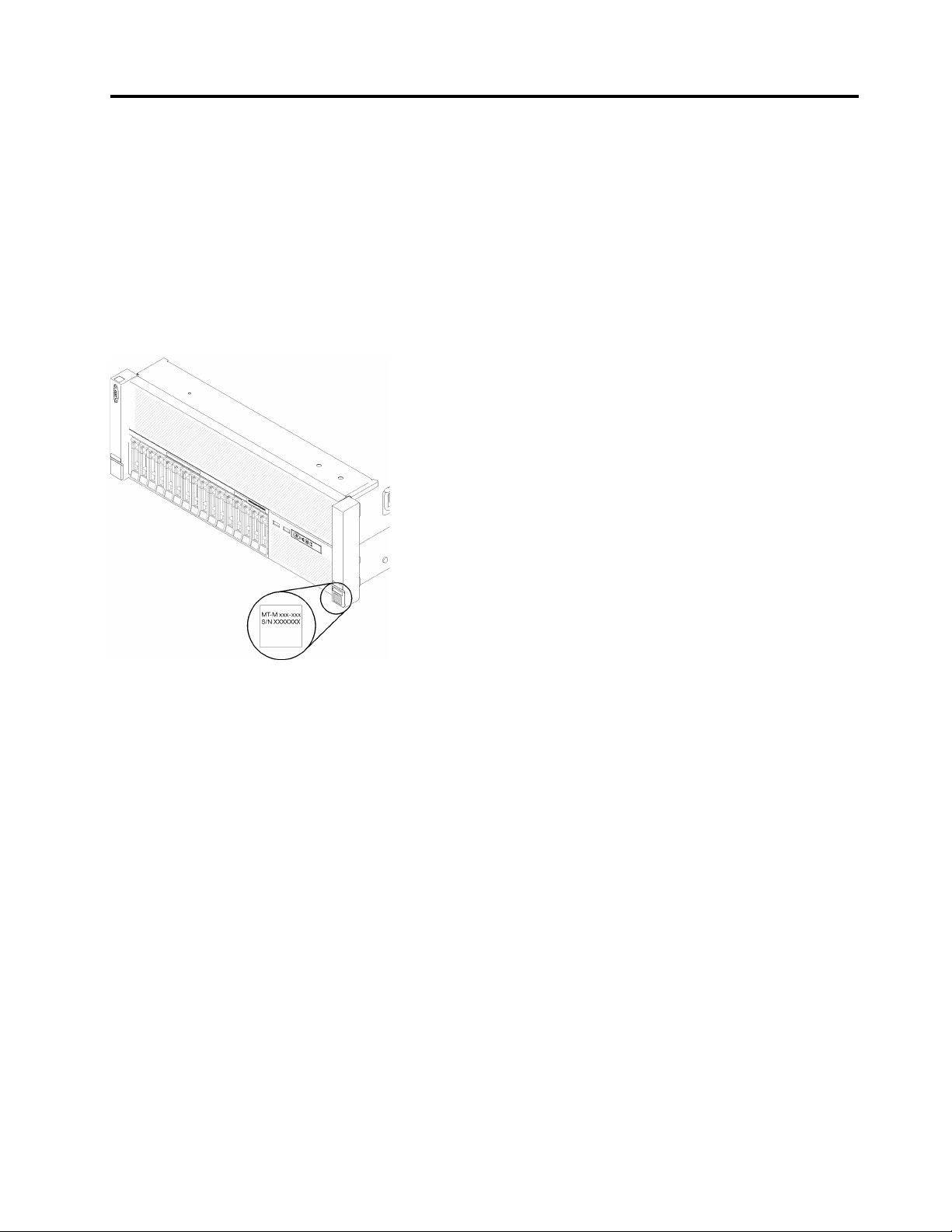
Figure 3 “Location of the machine type, model, and serial number” on page 15 shows the location of the
label containing the machine type, model, and serial number.
Figure 3. Location of the machine type, model, and serial number
The model number and serial number are on the ID label on the front of the server, as shown in the following
illustrations. You can also add other system information labels to the front of the server in the customer label
spaces.
XClarity Controller network access label
In addition, the XClarity Controller network access label is attached to the pull-out information tab located
near the center of the front view, with MAC address accessible with a pull.
© Copyright Lenovo 2017 15
Page 24

Figure 4. XClarity Controller network access label on the pull-out information tab
Front view
This section contains information about the controls, LEDs, and connectors on the front of the server.
The following illustration shows the controls, LEDs, and connectors on the front of the server.
Figure 5. Front view
Table 2. Components on the server front view
1 VGA connector 7 Network activity LED (green)
2 Drive activity LED (green) 8 Identification button/LED (blue)
3 Drive status LED (yellow) 9 System error LED (yellow)
4 USB 1 (USB 2.0 with Lenovo XClarity Controller
management)
5 USB 2
6 Power button/LED (green)
10 Front operator panel with optional pull-out LCD
display
11 Rack release latches
12 2.5-inch drive bays
16 ThinkSystem SR860 Setup Guide
Page 25
1 VGA connector:
Connect a monitor to this connector.
Notes:
• When the front VGA connector is in use, the rear VGA connector will be disabled.
• The maximum video resolution is 1920 x 1200 at 60 Hz.
2 Drive activity LED (green):
Each hot-swap drive comes with an activity LED, and when this LED is flashing, it indicates that the drive is in
use.
3 Drive status LED (yellow):
These LEDs are on SAS or SATA hard disk drives and solid-state drives. When one of these LEDs is lit, it
indicates that the drive has failed. When this LED is flashing slowly (one flash per second), it indicates that
the drive is being rebuilt. When the LED is flashing rapidly (three flashes per second), it indicates that the
controller is identifying the drive.
4 5 USB connectors:
Connect a USB device, such as a USB mouse, keyboard, or other device, to any of these connectors.
Following are detailed descriptions of each connector:
• USB 1: USB 2.0 with Lenovo XClarity Controller management
• USB 2: USB 2.0 or 3.0 (depending on the model)
6 Power button/LED (green):
Press the power button to turn the server on and off manually. The states of the power LED are as follows:
Off: No power supply is properly installed, or the LED itself has failed.
Flashing rapidly (4 times per second): The server is turned off and is not ready to be turned on. The
power-control button is disabled. This will last approximately 5 to 10 seconds.
Flashing slowly (once per second): The server is turned off and is ready to be turned on. You can press
the power-control button to turn on the server.
Solid on: The server is turned on.
7 Network activity LED (green):
When this LED is lit, it indicates that the server is transmitting to or receiving signals from the Ethernet LAN.
8 Identification button/LED (blue):
Press this button to visually locate the server among other servers. Use this LED to visually locate the server
among other servers. You can use Lenovo XClarity Controller to turn this LED on and off.
9 System error LED (yellow):
When this yellow LED is lit, it indicates that a system error has occurred. This LED can be controlled by the
Lenovo XClarity Administrator. Information provided from the LCD display of the front operator panel could
also help isolate an error.
10 Front operator panel with optional pull-out LCD display:
Chapter 2. Server components 17
Page 26
This panel contains controls and LEDs that provide information about the status of the server.
11 Rack release latches:
Press the latch on both sides in the front of the server to remove the server out of the rack.
12 2.5-inch drive bays:
Install 2.5-inch drives to these bays. See “Install a 2.5-inch hot-swap drive” on page 77 for more details.
Front operator panel
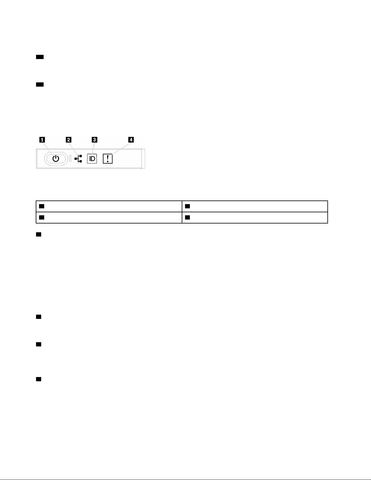
The following illustration shows the controls and LEDs on the front operator panel.
Figure 6. Front operator panel
Table 3. Buttons and LEDs on the front operator panel
1 Power button/LED (green) 3 Identification button/LED (blue)
2 Network activity LED (green) 4 System error LED (yellow)
1 Power button/LED (green)
Press this button to turn the server on and off manually. The states of the power LED are as follows:
Off: No power supply is properly installed, or the LED itself has failed.
Flashing rapidly (4 times per second): The server is turned off and is not ready to be turned on. The
power-control button is disabled. This will last approximately 5 to 10 seconds.
Flashing slowly (once per second): The server is turned off and is ready to be turned on. You can press
the power-control button to turn on the server.
Solid on: The server is turned on.
2 Network activity LED (green)
When this LED is lit, it indicates that the server is transmitting to or receiving signals from the Ethernet LAN.
3 Identification button/LED (blue)
Use this blue LED to visually locate the server among other servers. This LED is also used as a presence
detection button. You can use Lenovo XClarity Administrator to light this LED remotely.
4 System error LED (yellow)
When this yellow LED is lit, it indicates that a system error has occurred. This LED can be controlled by the
Lenovo XClarity Administrator. Information provided from the LCD display of the front operator panel could
also help isolate an error.
18
ThinkSystem SR860 Setup Guide
Page 27
Front operator panel with LCD display
The following section includes an overview of the LCD system information display panel of front operator
panel, which displays various types of information about the server.
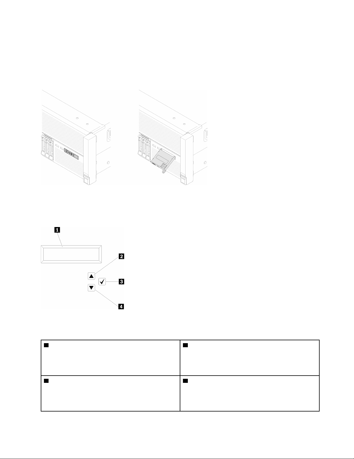
Depends on the configuration, your front operator panel may come with a LCD display, which is accessible
with a pull on the latch on the right of the front operator panel.
Figure 7. Front operator panel and LCD display
The LCD system information display panel attached to the front of the server allows quick access to system
status, firmware, network, and health information.
Figure 8. System information and control of the front operator panel
Table 4. System information and control of the front operator panel
1 System information:
System information, including system name, system
status, temperature, power consumption and UEFI/POST
code, is displayed here.
3 Select button:
Press this button to make your selection from the menu
options.
2 Scroll up button:
Press this button to scroll up or scroll to the left in the
main menu to locate and select the system information
that you want displayed.
4 Scroll down button:
Press this button to scroll down or scroll to the right in the
main menu to location and select the system information
that you want displayed.
Chapter 2. Server components 19
Page 28
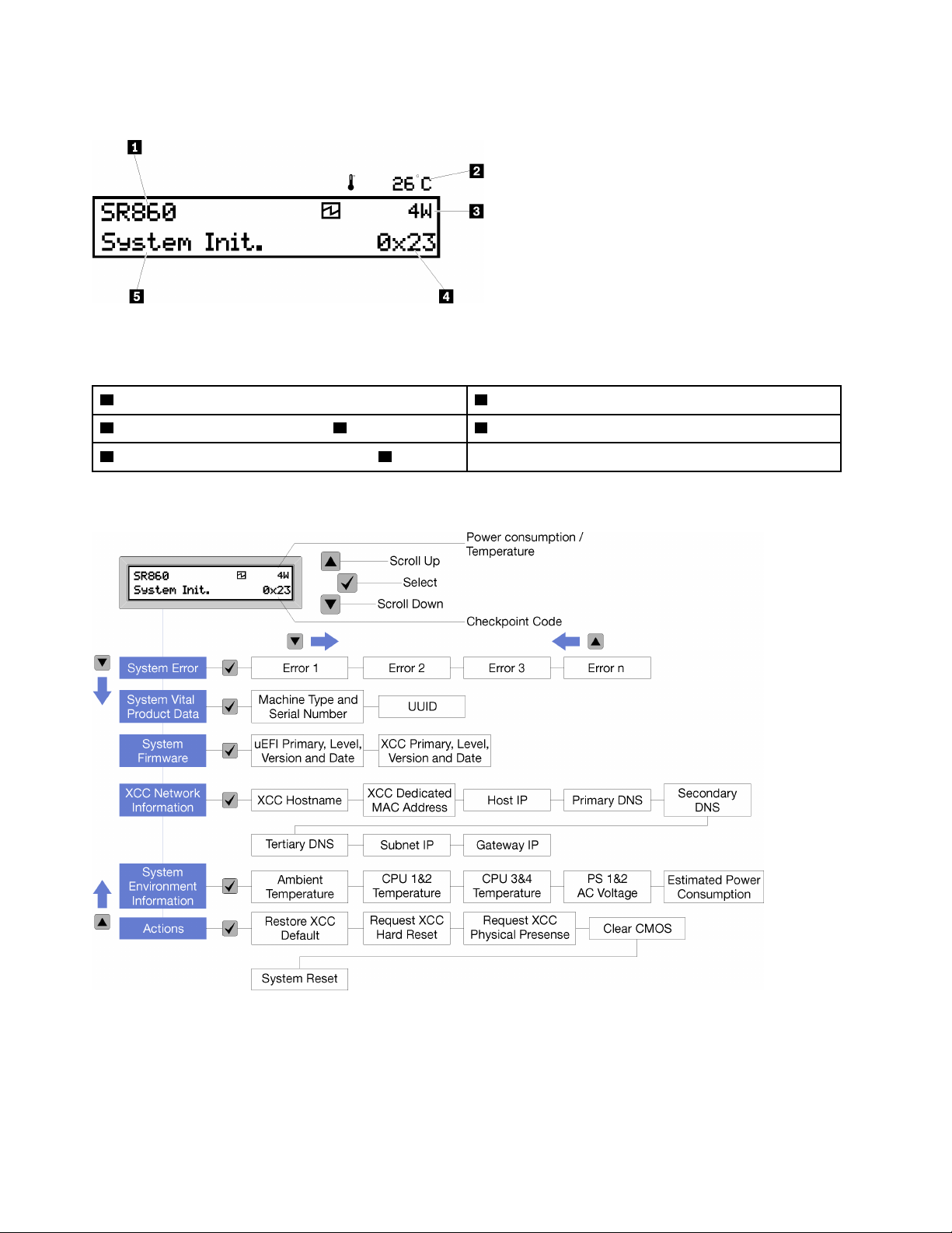
Following is an example of the information on the display panel.
Figure 9. System information on LCD display panel
Table 5. System information display panel of front operator panel
1 System name (ThinkSystem SR860) 4 Checkpoint code
2 Temperature (blinking in turns with 3 ) 5 System status
3 Power consumption (blinking in turns with 2 )
The option menu UI flow on the LCD display is illustrated as following.
Figure 10. Front operator panel option menu UI flow
Following is the list of options available on the front operator panel. Switch between an option and the
subordinate information entries with Select (√) button, and switch among options or information entries with
Scroll up (▼) and Scroll down (▲) buttons.
20
ThinkSystem SR860 Setup Guide
Page 29

Table 6. Options available on the front operator panel
Option
Description
System error System error provides the total number of errors the system encountered, and the
description of these errors. The information is displayed as following:
System Has Encountered X Errors
Whereas X is the total number of system errors encountered. Access error descriptions
with select button, and switch among the descriptions with scroll up and down buttons.
Note: When only one error occurs, the LCD display panel displays error description
instead of number of errors encountered.
System vital product data System vital product data provides the following information:
• Machine type and serial number are displayed as following:
Machine Type: XXXXXXXX
Serial Num: YYYYYY
• UUID (universally unique identifier) is displayed as following:
UUID: ZZZZZZZZZZZZZZZZZZZZZZZZZZZZ
Whereas
• XXXXXXXX is the machine type.
• YYYYYY is the serial number.
• ZZZZZZZZZZZZZZZZZZZZZZZZZZZZ is the UUID
System firmware level System firmware level provides information about the following firmware:
• UEFI primary level is displayed as following:
UEFI Pri: TEEXXXX
vN.NN Date:YYYY-MM-DD
• XCC primary level is displayed as following:
XCC Pri: TEEXXXX
vN.NN Date:YYYY-MM-DD
Whereas
• XXXX is the level information.
• N.NN is the version number.
• YYYY is the year.
• MM is the month.
• DD is the date.
Chapter 2. Server components 21
Page 30

Table 6. Options available on the front operator panel (continued)
XCC network information XCC Network information provides the following XCC related network information:
• XCC hostname is displayed as following:
XCC Hostname:
XCC-NNNN
• XCC shared or extension MAC address is displayed as following:
XCC Dedicated MAC:
XX:XX:XX:XX:XX:XX
• IP Address is displayed as following:
IP Host IP:
Y.Y.Y.Y
• Primary DNS is displayed as following:
IP Primary DNS:
Y.Y.Y.Y
• Secondary DNS is displayed as following:
IP Secondary DNS:
Y.Y.Y.Y
• Tertiary DNS is displayed as following:
IP Tertiary DNS:
Y.Y.Y.Y
• Subnet IP is displayed as following:
IP Subnet IP:
Y.Y.Y.Y
• Gateway IP is displayed as following:
IP Gateway IP:
Y.Y.Y.Y
Whereas
• NNNN is the machine type.
• XX.XX:XX:XX:XX:XX is a MAC address.
• Y.Y.Y.Y is an IPv4 or IPv6 address.
System environmental
information
System environmental information provides the following information:
• Ambient temperature is displayed as following:
Ambient
Temperature: XX C
• Processor temperature is displayed as following:
CPU1 Temperature: XX C
CPU2 Temperature: XX C
• AC input voltage is displayed as following:
• Estimated power consumption is displayed as following:
Whereas
22 ThinkSystem SR860 Setup Guide
CPU3 Temperature: XX C
CPU4 Temperature: XX C
Switch between CPU1/2 and CPU3/4 with scroll up and down buttons.
PS1 AC Voltage: YYY V
PS2 AC Voltage: YYY V
Sytem Power: ZZ W
Page 31

Table 6. Options available on the front operator panel (continued)
• XX is the temperature.
• YYY is the AC voltage.
• ZZ is the wattage.
Actions Actions provides the following available actions, which come in effect by pressing and
holding on the select button for three seconds:
• Restore XCC default settings is displayed as following:
RESTORE XCC DEFAULTS?
HOLD v FOR 3s
• Restart XCC is displayed as following:
REQUEST XCC HARD RESET?
HOLD v FOR 3s
• Request XCC physical presence is displayed as following:
REQUEST XCC PHY. PRES.?
HOLD v FOR 3s
• Clear CMOS is displayed as following:
CLEAR CMOS?
HOLD v FOR 3s
Note: This action is only available when the system power is off.
• System reboot is displayed as following:
SYSTEM RESET BUTTOM?
HOLD v FOR 3s
Rear view
This section contains information about the LEDs and connectors on the rear of the server.
The following illustrations show the connectors and LEDs on the rear of the server.
There are two sections show the different components on the rear server, see section “Connectors and LEDs
on the rear server” on page 24 and section “Expansion slots on the rear server” on page 26 for more
information.
Chapter 2. Server components 23
Page 32
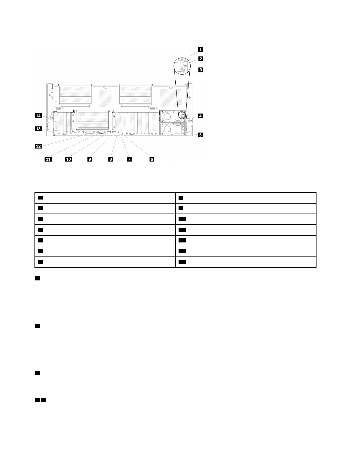
Connectors and LEDs on the rear server
Figure 11. Rear view
Table 7. Components on the server rear view
1 AC power LED (green) 8 Identification LED (blue)
2 DC power LED (green) 9 USB 4 (USB 3.0)
3 Power supply error LED (yellow) 10 USB 3 (USB 3.0)
4 Power supply unit 2
5 Power supply unit 1
6 System error LED (yellow)
7 Identification button
1 AC power LED:
11 Serial connector
12 VGA connector
13 NMI button
14 Lenovo XClarity Controller network connector
Each hot-swap power supply comes with an AC power LED and a DC power LED. When the AC power LED
is lit, it indicates that sufficient power is being supplied to the power supply through the power cord. During
normal operation, both the AC and DC power LEDs are lit. For more information, see “Lightpath Diagnostics”
in ThinkSystem SR860 Maintenance Manual.
2 DC power LED:
Each hot-swap power supply comes with a DC power LED and an AC power LED. When the DC power LED
is lit, it indicates that the power supply is supplying adequate DC power to the system. During normal
operation, both the ACand DC power LEDs are lit. For more information, see “Lightpath Diagnostics” in
ThinkSystem SR860 Maintenance Manual.
3 Power-supply error LED:
When the power-supply error LED is lit, it indicates that the power supply has failed.
4 5 Power supply units:
Install power supply units to these bays, connect them to power cords. Make sure the power cords are
connected properly. Following are the power supplies supported by this system:
24
ThinkSystem SR860 Setup Guide
Page 33
• 750-watt platinum power supply
– input power 115V or 230V ac
• 1100-watt platinum power supply
– input power 115V or 230V ac
• 1600-watt platinum power supply
– input power 230V ac
• 2000-watt platinum power supply
– input power 230V ac
6 System error LED (yellow):
When this yellow LED is lit, it indicates that a system error has occurred. This LED can be controlled by the
Lenovo XClarity Administrator. Information provided from the LCD display of the front operator panel could
also help isolate an error.
7 Identification button:
Press this button to visually locate the server among other servers. This button is functionally equivalent to
the identification button on the front of the server.
8 Identification LED (blue):
Use this LED to visually locate the server among other servers. You can use Lenovo XClarity Controller to
turn this LED on and off. This LED is functionally equivalent to the identification LED on the front of the
server.
9 10 USB connectors (USB 3.0):
Connect a USB device, such as a USB mouse, keyboard, or other device, to any of these connectors.
11 Serial connector:
Connect a 9-pin serial device to this connector. The serial port is shared with the Lenovo XClarity Controller.
The Lenovo XClarity Controller can take control of the shared serial port to redirect serial traffic, using Serial
over LAN (SOL).
12 VGA connector:
Connect a monitor to this connector.
Notes:
• When the front VGA connector is in use, the rear VGA connector will be disabled.
• The maximum video resolution is 1920 x 1200 at 60 Hz.
13 NMI button:
Press this button to force a nonmaskable interrupt to the processor. You might have to use a pen or the end
of a straightened paper clip to press the button. You can also use it to force a blue-screen memory dump.
Use this button only when you are directed to do so by Lenovo Support.
14 Lenovo XClarity Controller network connector:
Use this connector to manage the server, by using a dedicated management network. If you use this
connector, the Lenovo XClarity Controller cannot be accessed directly from the production network. A
dedicated management network provides additional security by physically separating the management
Chapter 2. Server components 25
Page 34
network traffic from the production network. You can use the Setup utility to configure the server to use a
dedicated systems-management network or a shared network.
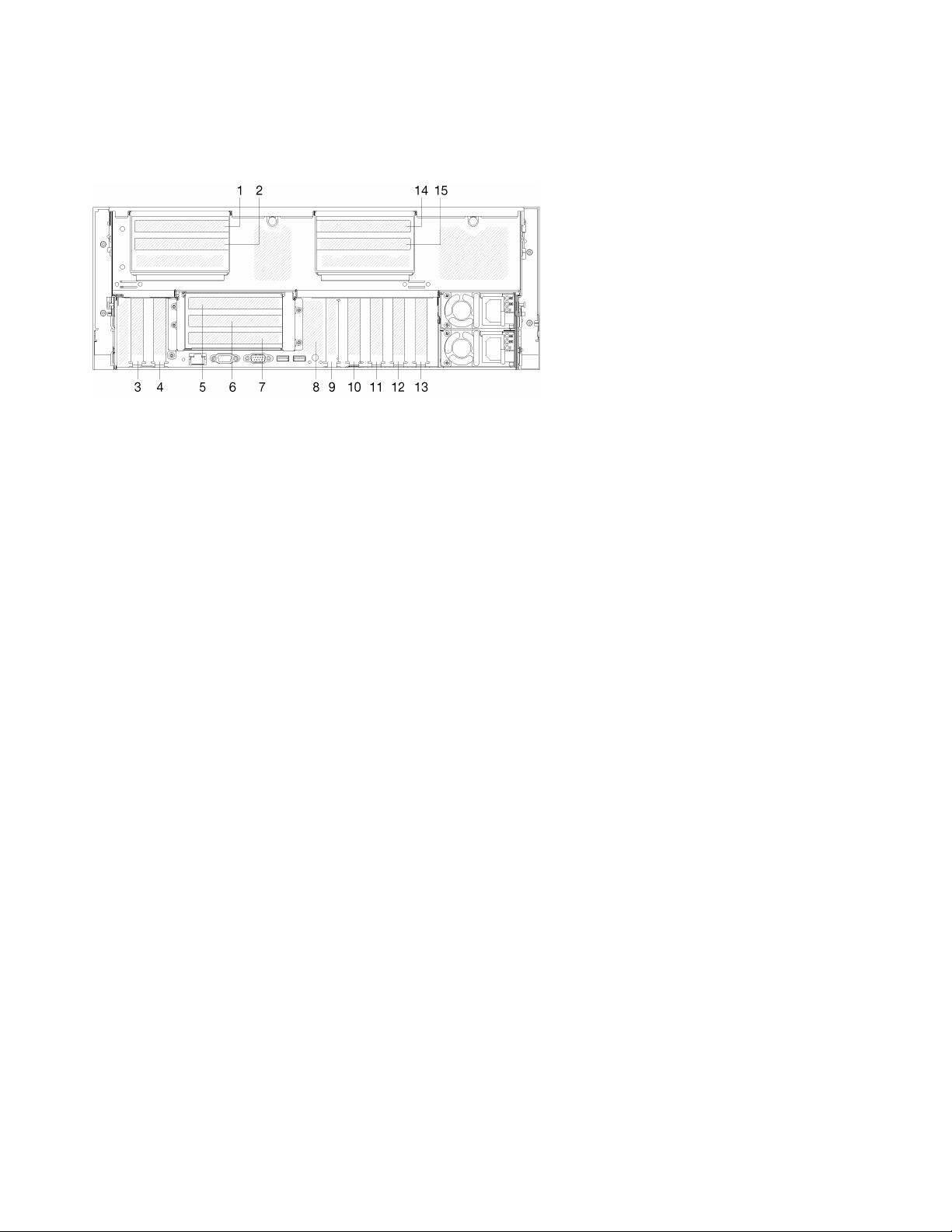
Expansion slots on the rear server
Figure 12. Rear view (PCIe slot number)
• PCIe slot 1 and 2 (on 4U PCIe riser assembly 2):
PCIe slot 1 and 2 are available with a 4U PCIe riser card installed in slot 3. Following are the 4U PCIe riser
cards supported by this server.
– ThinkSystem SR860 2x8 PCIe FH riser 2 provides:
– Slot 1: PCI Express 3.0 x8
– Slot 2: PCI Express 3.0 x8
Note:
– The PCIe riser card uses x16 mechanical connectorswith x8 signals.
– The riser card supports HBA and network/RAID adapter with external connection.
– ThinkSystem SR860 1x16 PCIe FH riser 2 provides:
– Slot 1: GPU
– Slot 2: Not available in the riser card
• PCIe slot 3:
PCI Express 3.0 x16 (supports PCIe switch card, not available after the 4U PCIe riser card installed)
• PCIe slot 4:
PCI Express 3.0 x8 (supports RAID adapters for SATA/SAS drives)
• PCIe slot 5 - 7 (on PCIe riser card 1):
Install a full-height PCIe riser card into this slot. Following are the PCIe riser cards supported by this
server.
– x8/x8/x8 PCIe full-height riser assembly provides:
– Slot 5: PCI Express 3.0 x8 (network adapters with RJ45 connectors are not supported)
– Slot 6: PCI Express 3.0 x8
– Slot 7: PCI Express 3.0 x8
– x8/x8/x8 ML2 PCIe full-height riser assembly provides:
– Slot 5: PCI Express 3.0 x8 (network adapters with RJ45 connectors are not supported)
– Slot 6: PCI Express 3.0 x8
– Slot 7: Customized slot for x8 ML2 adapter
26
ThinkSystem SR860 Setup Guide
Page 35

– x8/x16 ML2 PCIe full-height riser assembly provides:
– Slot 5: PCI Express 3.0 x8 (network adapters with RJ45 connectors are not supported)
– Slot 6: Not available in the riser card
– Slot 7: Customized slot for x16 ML2 adapter
• M.2 backplane (slot 8):
Install M.2 backplane to this slot. See “Install the M.2 backplane” on page 91 and “Install an M.2 drive in
the M.2 backplane” on page 90 for more details.
• LOM adapter (slot 9):
Insert LOM adapter into this slot (see “System-board connectors” in ThinkSystem SR860 Maintenance
Manual for the location of the LOM adapter slot on the system board and “LOM adapter replacement” in
ThinkSystem SR860 Maintenance Manual for information about the installation of the LOM adapter.
• PCIe slot 10:
PCI Express 3.0 x8
• PCIe slot 11:
PCI Express 3.0 x8
• PCIe slot 12:
PCI Express 3.0 x8 supports RAID adapters for SATA/SAS drives
• PCIe slot 13:
PCI Express 3.0 x16 (supports PCIe switch card, not available after the 4U PCIe riser card installed)
• PCIe slot 14 and 15 (on 4U PCIe riser assembly 3):
PCIe slot 14 and 15 are available with a 4U PCIe riser card installed in slot 13. Following are the 4U PCIe
riser cards supported by this server.
– ThinkSystem SR860 2x8 PCIe FH riser 3 provides:
– Slot 14: PCI Express 3.0 x8
– Slot 15: PCI Express 3.0 x8
Note:
– The PCIe riser card uses x16 mechanical connectorswith x8 signals.
– The riser card supports HBA and network/RAID adapter with external connection.
– ThinkSystem SR860 1x16 PCIe FH riser 3 provides:
– Slot 14: GPU
– Slot 15: Not available in the riser card
Optional processor and memory expansion tray
Use this information to locate the connectors and LEDs on the optional processor and memory expansion
tray.
The following illustrations show the connectors and LEDs on the processor and memory expansion tray.
Chapter 2. Server components 27
Page 36
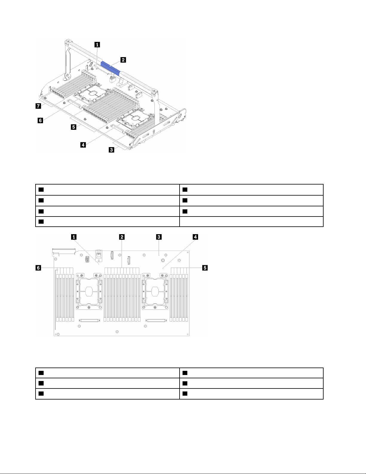
Figure 13. Optional processor and memory expansion tray
Table 8. Components on the optional processor and memory expansion tray
1 Power supply 2 connector 5 DIMM slot 31-42
2 Tray handle 6 Processor 3
3 DIMM slot 43-48 7 DIMM slot 25-30
4 Processor 4
Figure 14. LEDs on the optional processor and memory expansion tray
Table 9. LEDs on the optional processor and memory expansion tray
1 Processor 3 error LED 4 Processor 4 error LED
2 DIMM slot 31-42 error LEDs 5 DIMM slot 43-48 error LEDs
3 Expansion board error LED 6 DIMM slot 25-30 error LEDs
28 ThinkSystem SR860 Setup Guide
Page 37
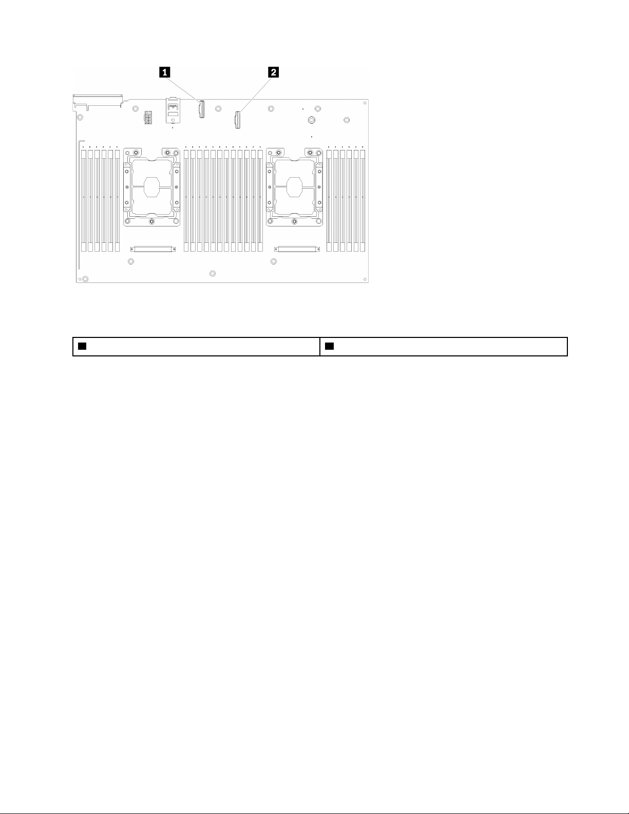
Figure 15. Connectors on the optional processor and memory expansion tray
Table 10. Connectors on the optional processor and memory expansion tray
1 NVMe signal cable connector 0-1 2 NVMe signal cable connector 2-3
Chapter 2. Server components 29
Page 38
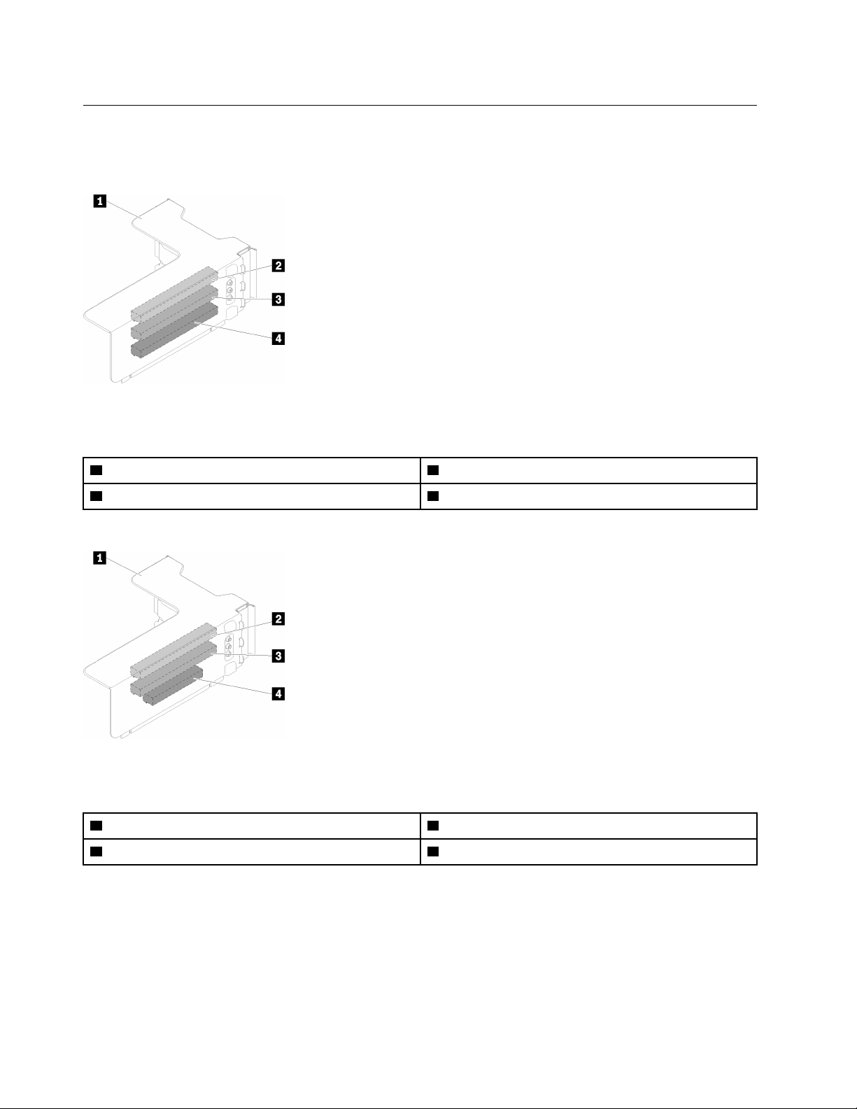
PCIe riser cards
Use this information to locate the connectors on the optional PCIe riser cards.
x8/x8/x8 PCIe FH Riser Assembly
Figure 16. x8/x8/x8 PCIe FH Riser Assembly
Table 11. Components of x8/x8/x8 PCIe FH Riser Assembly
1 PCIe full-height riser cage 3 PCI Express 3.0 x8 (slot 6)
2 PCI Express 3.0 x8 (slot 5) 4 PCI Express 3.0 x8 (slot 7)
x8/x8/x8 ML2 PCIe FH Riser Assembly
Figure 17. x8/x8/x8 ML2 PCIe FH Riser Assembly
Table 12. Components of x8/x8/x8 ML2 PCIe FH Riser Assembly
1 PCIe full-height riser cage 3 PCI Express 3.0 x8 (slot 6)
2 PCI Express 3.0 x8 (slot 5) 4 Customized slot for ML2 adapter (slot 7)
30 ThinkSystem SR860 Setup Guide
Page 39
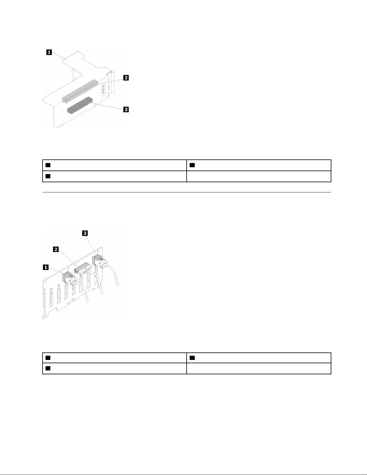
x8/x16 ML2 PCIe FH Riser Assembly
Figure 18. x8/x16 ML2 PCIe FH Riser Assembly
Table 13. Components of x8/x16 ML2 PCIe FH Riser Assembly
1 PCIe full-height riser cage 3 Customized slot for ML2 adapter (slot 7)
2 PCI Express 3.0 x8 (slot 5)
2.5-inch drive backplanes
Use this information to locate the connectors on the optional 2.5-inch drive backplanes.
2.5-inch SATA/SAS 8-bay backplane
Figure 19. 2.5-inch SATA/SAS 8-bay backplane
Table 14. Connectors on 2.5-inch SATA/SAS 8-bay backplane
1 SATA/SAS connector 1 3 SATA/SAS connector 0
2 Power/configuration cable connector
2.5-inch SATA/SAS 8-bay backplane comes with:
• Eight SATA/SAS drive connectors with bay numbers of 0-7 or 8-15, depending on the location installed.
• One power/configuration connector
• Two SATA/SAS connectors (0, 1)
Chapter 2. Server components 31
Page 40
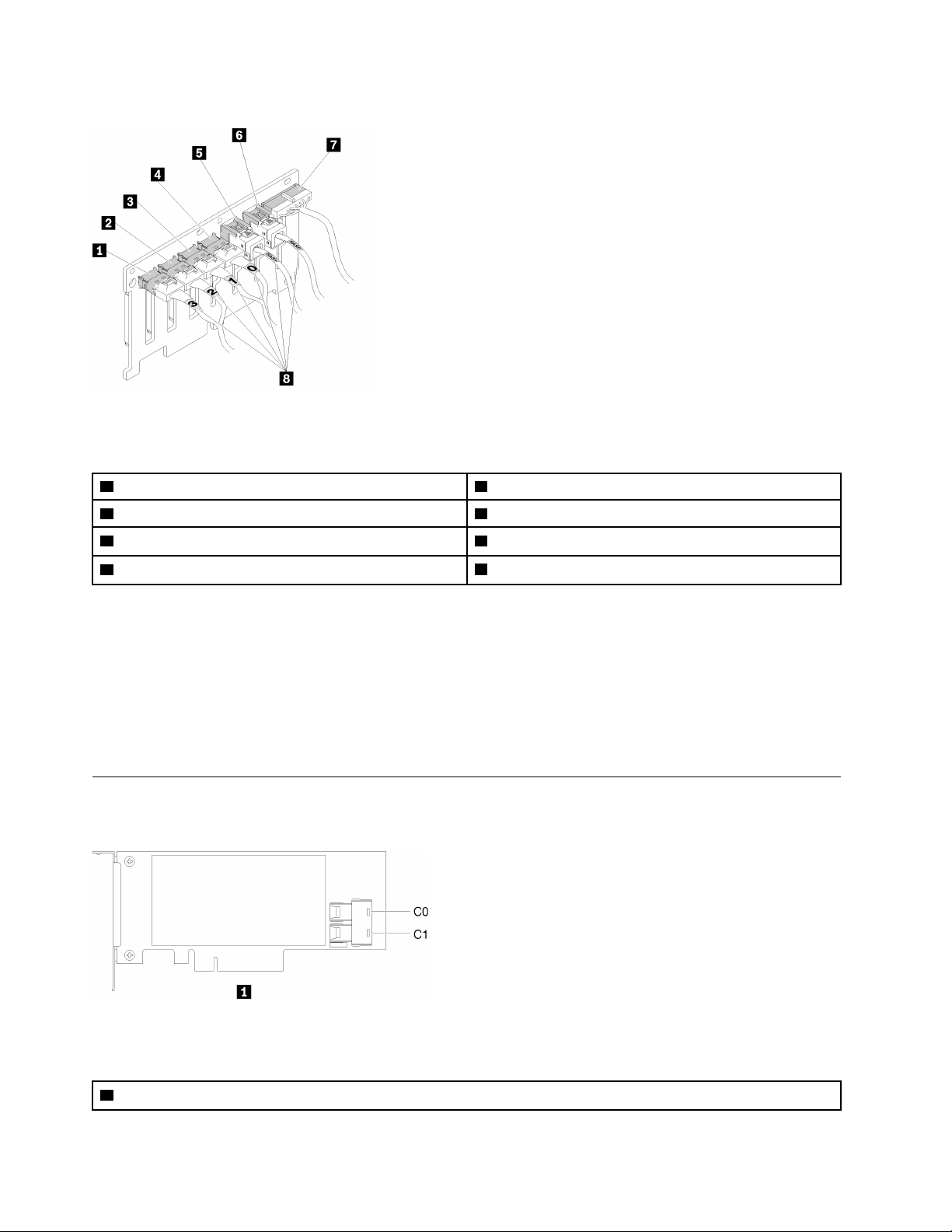
2.5-inch AnyBay (SATA/SAS/NVMe) 8-bay backplane
Figure 20. 2.5-inch AnyBay (SATA/SAS/NVMe) 8-bay backplane
Table 15. Connectors on 2.5-inch AnyBay (SATA/SAS/NVMe) 8-bay backplane
1 SATA/SAS/NVMe connector 3 5 SATA/SAS connector 1
2 SATA/SAS/NVMe connector 2 6 SATA/SAS connector 0
3 SATA/SAS/NVMe connector 1 7 Power/configuration cable connector
4 SATA/SAS/NVMe connector 0 8 Cable numbering labels
2.5-inch AnyBay (SATA/SAS/NVMe) 8-bay backplane comes with:
• Four SATA/SAS drive connectors with bay numbers of 0-3 or 8-11, depending on the location installed.
• Four NVMe drive connectors with bay numbers of 4-7 or 12-15, depending on the location installed.
• One power/configuration cable connector
• Two SATA/SAS connectors (0, 1)
• Four NVMe connectors (0, 1, 2, 3)
RAID adapters
Use this information to locate the connectors on the optional RAID adapters.
Figure 21. Connectors on SATA/SAS RAID adapter (8i)
Table 16. SATA/SAS RAID adapter (8i)
1 SATA/SAS RAID adapter (8i) with two SATA/SAS connectors (C0, C1)
32 ThinkSystem SR860 Setup Guide
Page 41
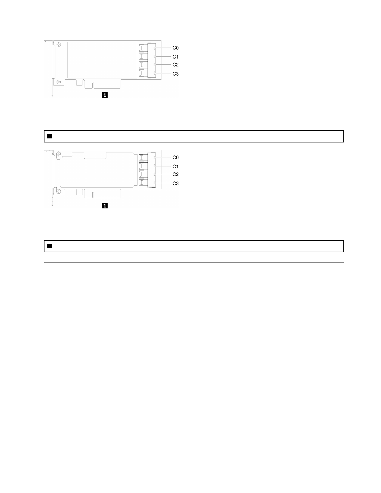
Figure 22. Connectors on SATA/SAS RAID adapter (16i)
Table 17. SATA/SAS RAID adapter (16i)
1 SATA/SAS RAID adapter (16i) with four SATA/SAS connectors (C0, C1, C2, C3)
Figure 23. Connectors on PCIe switch card
Table 18. PCIe switch card
1 PCIe switch card with four SATA/SAS connectors (C0, C1, C2, C3)
Internal cable routing
This section provides information about routing the cables when you install components in the server.
For more information about the requirements for cables and connecting devices, see the documentation that
comes with these devices.
Guideline for cable routing for 2.5-inch drives
General guideline for cable routing for 2.5-inch drives.
1. Make sure all the signal cables go through the cable guides.
Chapter 2. Server components 33
Page 42
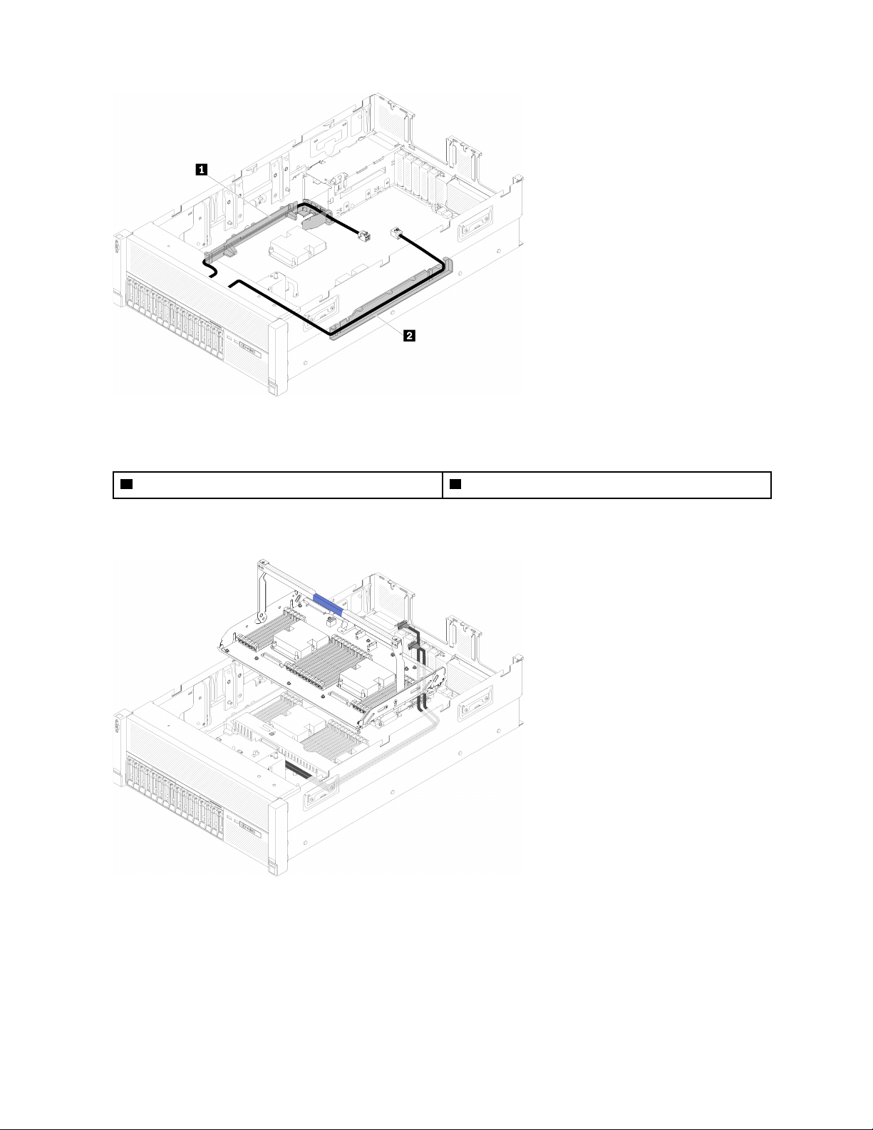
Figure 24. Cable guide locations
Table 19. Cable guide
1 Cable guide 2 Cable guide
2. If the processor and memory expansion tray is installed in the server, lift the tray and route the direct
NVMe signal cables in the cable guide and behind the tray.
Figure 25. Routing the NVMe cables to the processor and memory expansion tray
Connect the direct NVMe signal cables to the NVMe connectors on the processor and memory
expansion tray.
34
ThinkSystem SR860 Setup Guide
Page 43
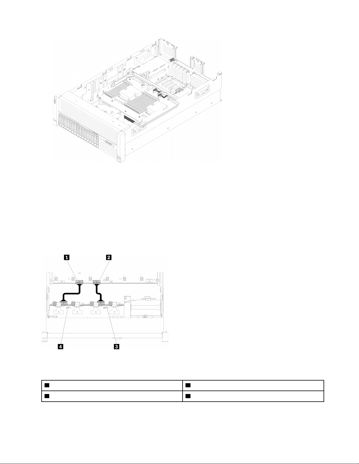
Figure 26. Connecting the NVMe cables to the processor and memory expansion tray
Before starting cable routing for 2.5-inch drives:
1. Remove the fan cage assembly (see “Remove the fan cage assembly” on page 69).
2. Remove the system board air baffle (see “Remove the system board air baffle and the power interposer”
on page 66) or the processor and memory expansion tray and the processor and memory expansion tray
air baffle (see “Remove the processor and memory expansion tray” on page 67).
Connecting power cable
Connect power cables for drive backplanes as in the following illustration.
Figure 27. Location of power cable connectors on the system board
Table 20. Power cable connectors on the system board and the drive backplanes
1 Power cable connector on the system board 3 Power cable connector on the drive backplane
2 Power cable connector on the system board 4 Power cable connector on the drive backplane
Two types of drive backplanes are supported by this system:
Chapter 2. Server components 35
Page 44

• 2.5-inch SATA/SAS 8-bay backplane (referred to as “8-bay backplane”)
• 2.5-inch AnyBay 8-bay backplane (referred to as “AnyBay backplane”)
4U PCIe riser assemblies can be installed when the PCIe slot 3 or 13 are not occupied by PCIe adapters,
make sure the slots for 4U PCIe riser cards are available before the riser card installation.
Cable routing for 2.5-inch drives to one backplane
Use this section to route cables for 2.5-inch drives to one backplane.
Following is the list of combinations of cable routing for 2.5-inch drives to one backplane.
• “Connecting signal cables to one backplane” on page 36
– “One 8-bay backplane” on page 37
– “One AnyBay backplane” on page 38
– Two processors installed
– Four processors installed
Connecting signal cables to one backplane
When there is one backplane installed, see the following illustrations for cable routing.
36
ThinkSystem SR860 Setup Guide
Page 45
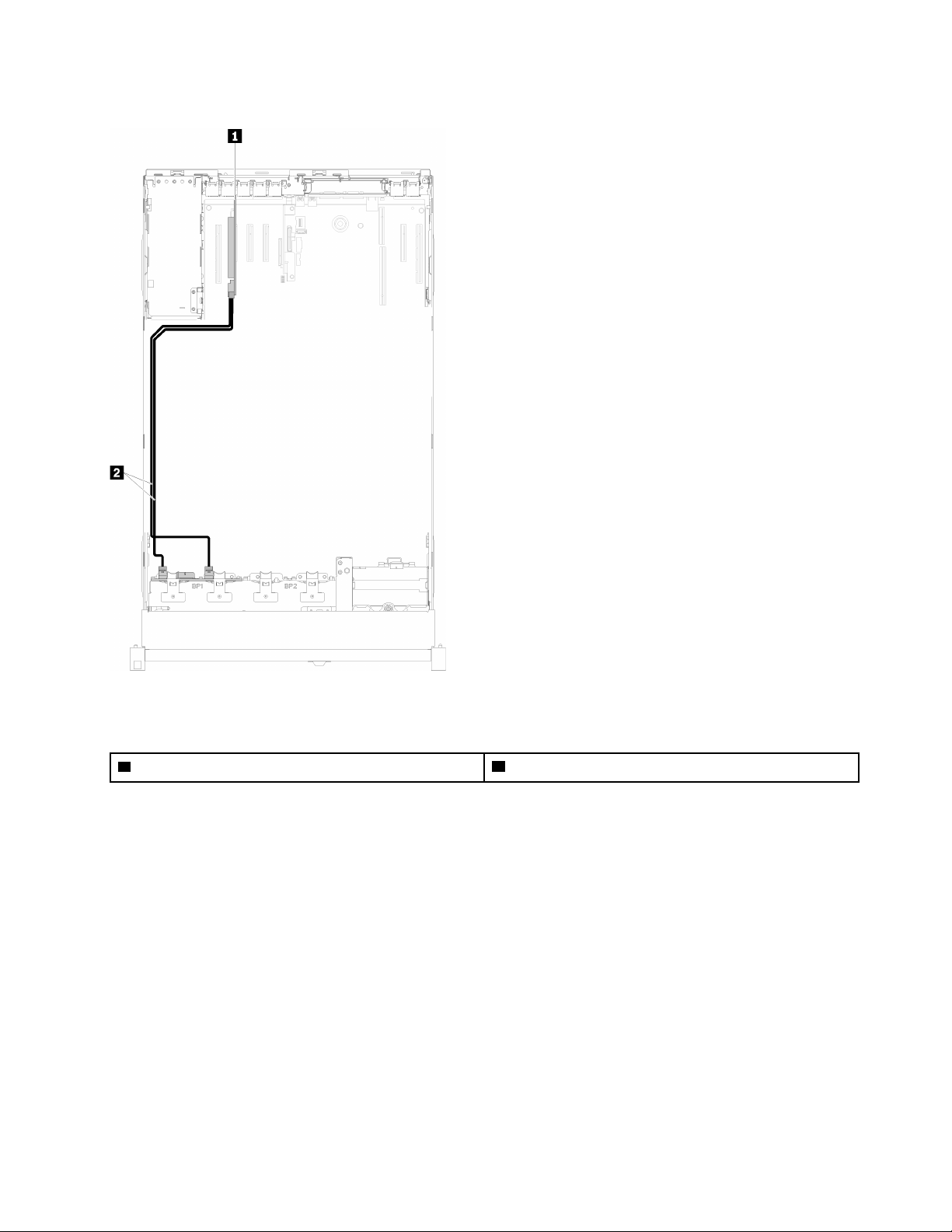
One 8-bay backplane
Figure 28. Cable routing, 8-bay backplane
Table 21. Cables and adapters for routing
1 SATA/SAS RAID adapter (8i) 2 SATA/SAS signal cables (720 mm)
Chapter 2. Server components 37
Page 46
One AnyBay backplane
Two processors installed
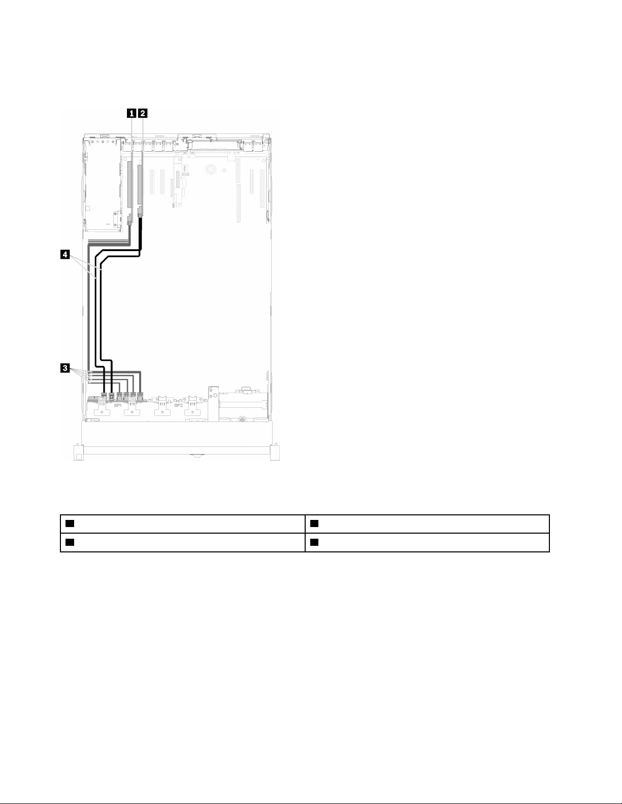
Figure 29. Cable routing, AnyBay backplane with two processors installed
Table 22. Cables and adapters for routing
1 PCIe switch card 3 NVMe signal cables for PCIe switch card
2 SATA/SAS RAID adapter (8i) 4 SATA/SAS signal cables (720 mm)
38 ThinkSystem SR860 Setup Guide
Page 47
Four processors installed
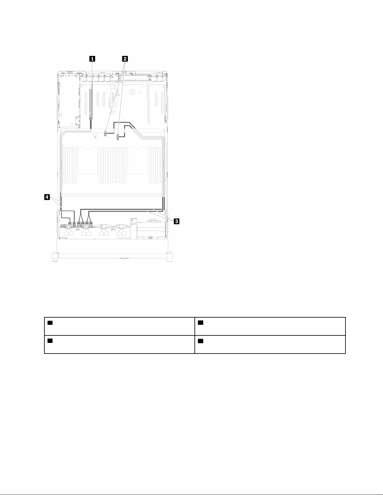
Figure 30. Cable routing, AnyBay backplane
Note: Install the processor and memory expansion tray before connecting the signal cables to NVMe
connector on the expansion tray.
Table 23. Cables and adapters for routing
1 SATA/SAS RAID adapter (8i)
2 NVMe connectors on the processor and memory
expansion tray
3 Direct NVMe signal cables for processor and memory
expansion tray
4 SATA/SAS signal cables (720 mm)
Cable routing for 2.5-inch drives to two backplanes
Use this section to understand how to route cables for 2.5-inch drives to two backplanes.
Following is the list of combinations of cable routing for 2.5-inch drives to two backplanes.
• “Connecting signal cables to two backplanes” on page 41
– “8-bay backplane + 8-bay backplane” on page 41
– “AnyBay backplane + 8-bay backplane ” on page 43
– Two processors installed
Chapter 2. Server components 39
Page 48

– Four processors installed
– “AnyBay backplane + AnyBay backplane” on page 47
– Two processors installed
– Four processors installed
40
ThinkSystem SR860 Setup Guide
Page 49
Connecting signal cables to two backplanes
When there are two backplanes installed, see the following illustrations for cable routing.
8-bay backplane + 8-bay backplane
Two options are available for this combination:
1. With SATA/SAS RAID adapter (16i)
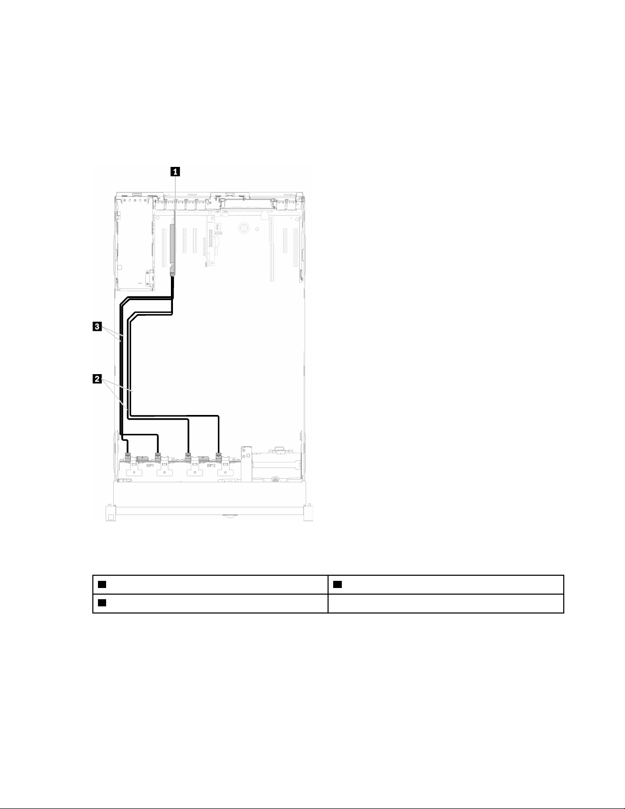
Figure 31. Cable routing, 8-bay backplane + 8-bay backplane
Table 24. Cables and adapters for routing
1 SATA/SAS RAID adapter (16i) 3 SATA/SAS signal cables (720 mm)
2 SATA/SAS signal cables (900 mm)
Chapter 2. Server components 41
Page 50
2. With SATA/SAS RAID adapter (8i)
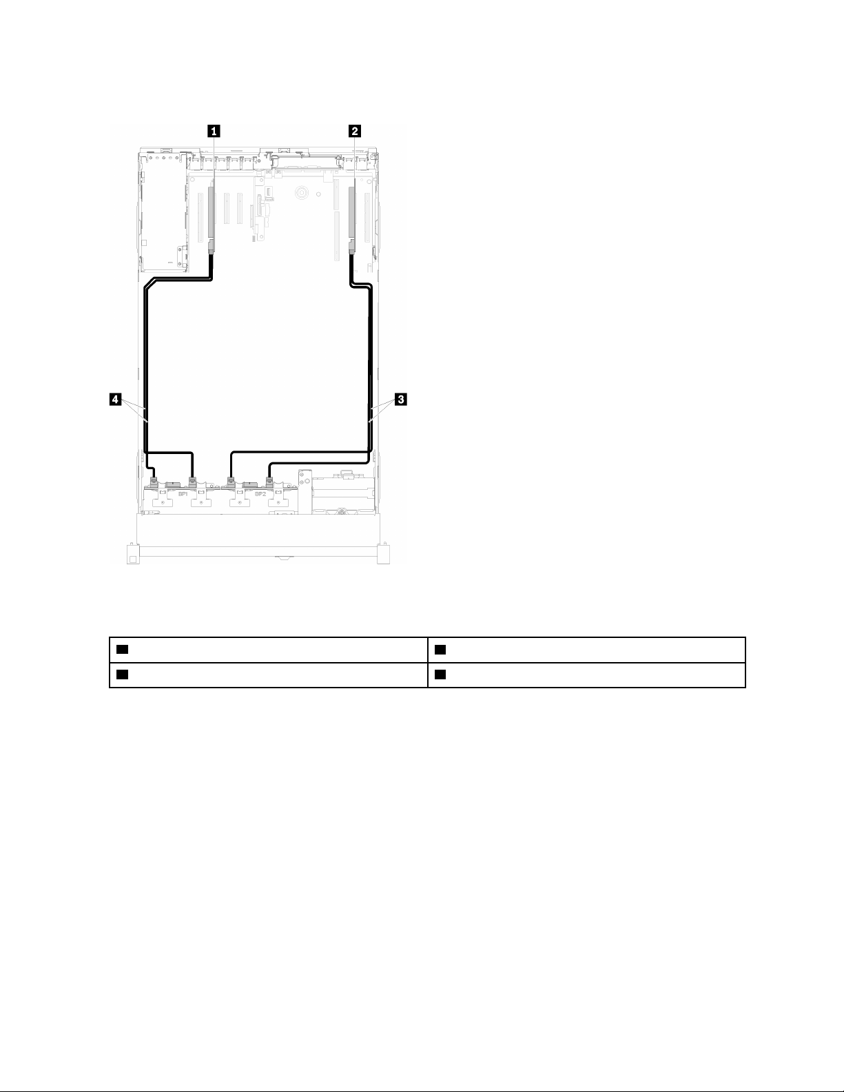
Figure 32. Cable routing, 8-bay backplane + 8-bay backplane
Table 25. Cables and adapters for routing
1 SATA/SAS RAID adapter (8i) 3 SATA/SAS signal cables (720 mm)
2 SATA/SAS RAID adapter (8i) 4 SATA/SAS signal cables (720 mm)
42 ThinkSystem SR860 Setup Guide
Page 51
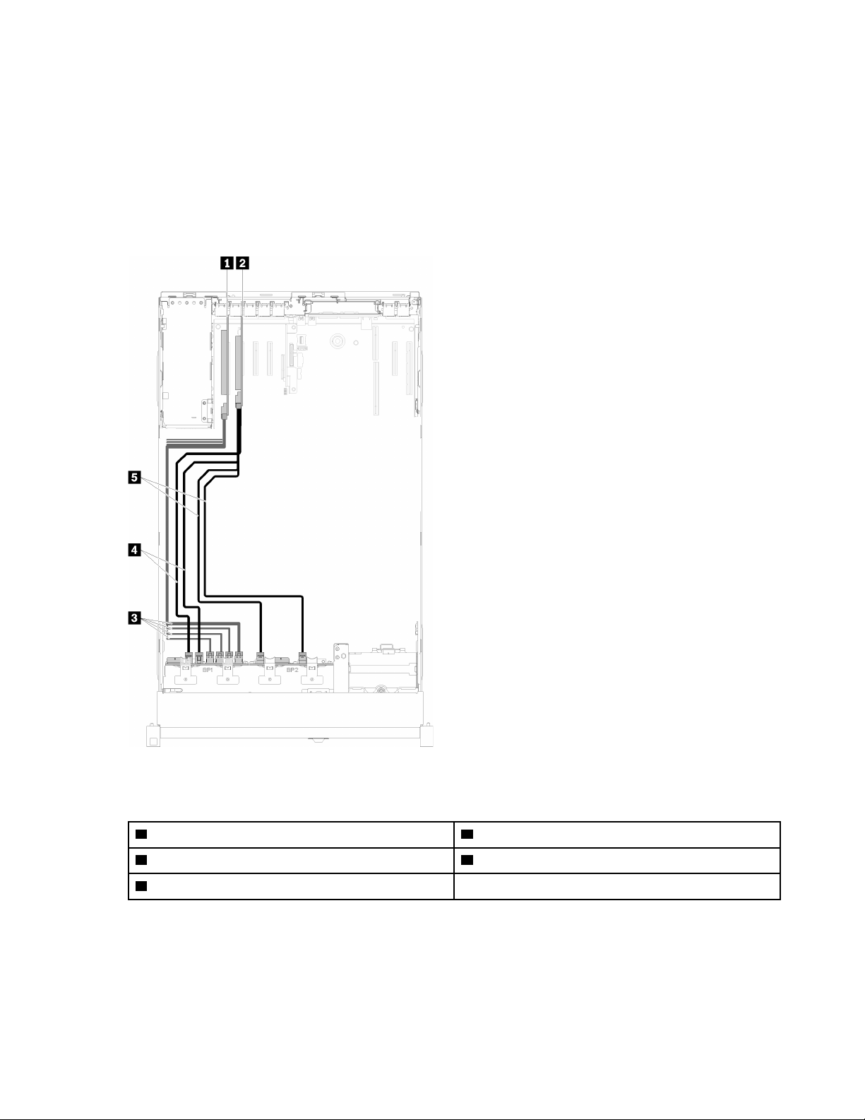
AnyBay backplane + 8-bay backplane
Two processors installed
Two options are available for this combination:
Attention: When installing a AnyBay backplane and a 8-bay backplane, always install the AnyBay backplane
to drive bay 0-7, and the 8-bay backplane to drive bay 8-15.
1. With SATA/SAS RAID adapter (16i)
Figure 33. Cable routing, AnyBay backplane + 8-bay backplane
Table 26. Cables and adapters for routing
1 PCIe switch card 4 SATA/SAS signal cables (720 mm)
2 SATA/SAS RAID adapter (16i) 5 SATA/SAS signal cables (900 mm)
3 NVMe signal cables for PCIe switch card
Chapter 2. Server components 43
Page 52
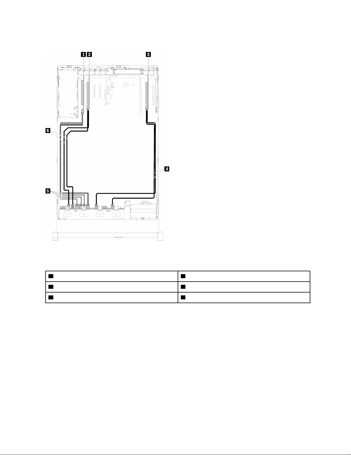
2. With SATA/SAS RAID adapter (8i)
Figure 34. Cable routing, AnyBay backplane + 8-bay backplane
Table 27. Cables and adapters for routing
1 PCIe switch card 4 SATA/SAS signal cables (720 mm)
2 SATA/SAS RAID adapter (8i) 5 NVMe signal cables for PCIe switch card
3 SATA/SAS RAID adapter (8i) 6 SATA/SAS signal cables (720 mm)
44 ThinkSystem SR860 Setup Guide
Page 53
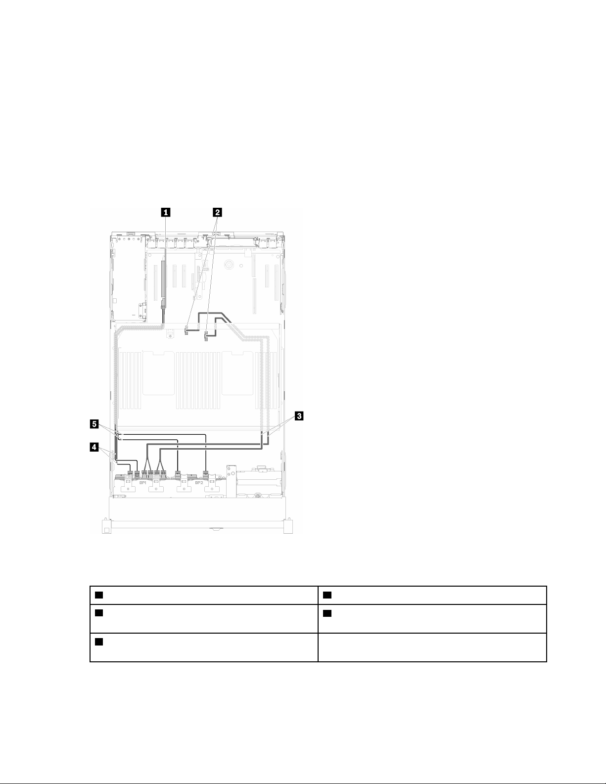
Four processors installed
Two options are available for this combination:
Notes:
• When installing a AnyBay backplane and a 8-bay backplane, always install the AnyBay backplane to drive
bay 0-7, and the 8-bay backplane to drive bay 8-15.
• Install the processor and memory expansion tray before connecting the signal cables to NVMe connector
on the expansion tray.
1. With SATA/SAS RAID adapter (16i)
Figure 35. Cable routing, AnyBay backplane + 8-bay backplane
Table 28. Cables and adapters for routing
1 SATA/SAS RAID adapter (16i) 4 SATA/SAS signal cables (720 mm)
2 NVMe connectors on the processor and memory
expansion tray
3 Direct NVMe signal cables for processor and
memory expansion tray
5 SATA/SAS signal cables (900 mm)
Chapter 2. Server components 45
Page 54
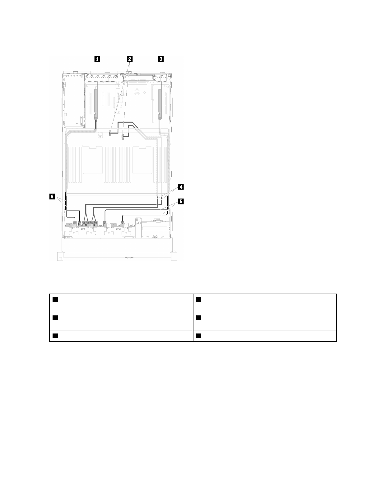
2. With SATA/SAS RAID adapter (8i)
Figure 36. Cable routing, AnyBay backplane + 8-bay backplane
Table 29. Cables and adapters for routing
1 SATA/SAS RAID adapter (8i)
4 Direct NVMe signal cables for processor and
memory expansion tray
2 NVMe connectors on the processor and memory
5 SATA/SAS signal cables (720 mm)
expansion tray
3 SATA/SAS RAID adapter (8i) 6 SATA/SAS signal cables (720 mm)
46 ThinkSystem SR860 Setup Guide
Page 55
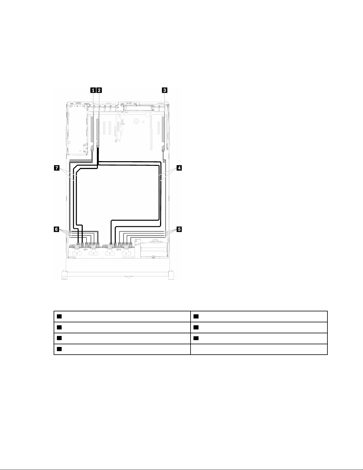
AnyBay backplane + AnyBay backplane
Two processors installed
Two options are available for this combination:
1. With SATA/SAS RAID adapter (16i)
Figure 37. Cable routing, AnyBay backplane + AnyBay backplane
Table 30. Cables and adapters for routing
1 PCIe switch card 5 NVMe signal cables for PCIe switch card
2 SATA/SAS RAID adapter (16i) 6 NVMe signal cables for PCIe switch card
3 PCIe switch card 7 SATA/SAS signal cables (720 mm)
4 SATA/SAS signal cables (900 mm)
Chapter 2. Server components 47
Page 56
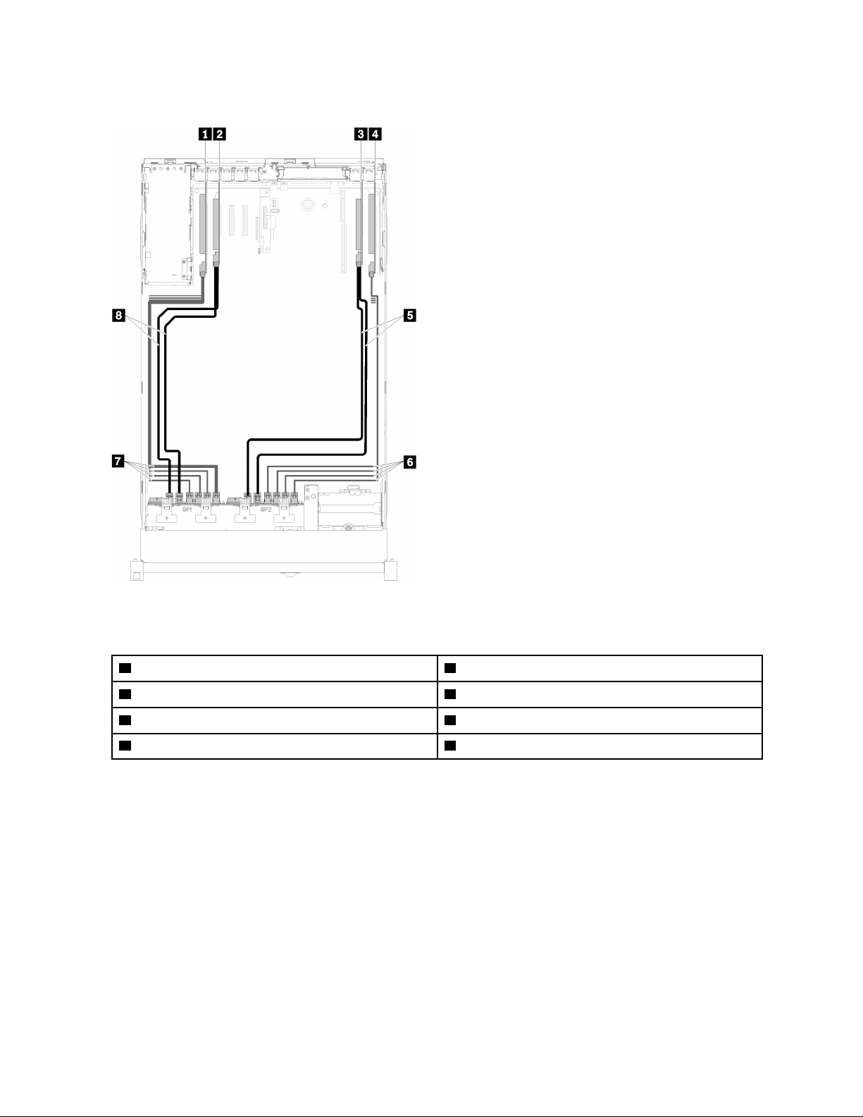
2. With SATA/SAS RAID adapter (8i)
Figure 38. Cable routing, AnyBay backplane + AnyBay backplane
Table 31. Cables and adapters for routing
1 PCIe switch card 5 SATA/SAS signal cables (720 mm)
2 SATA/SAS RAID adapter (8i) 6 NVMe signal cables for PCIe switch card
3 SATA/SAS RAID adapter (8i) 7 NVMe signal cables for PCIe switch card
4 PCIe switch card 8 SATA/SAS signal cables (720 mm)
48 ThinkSystem SR860 Setup Guide
Page 57
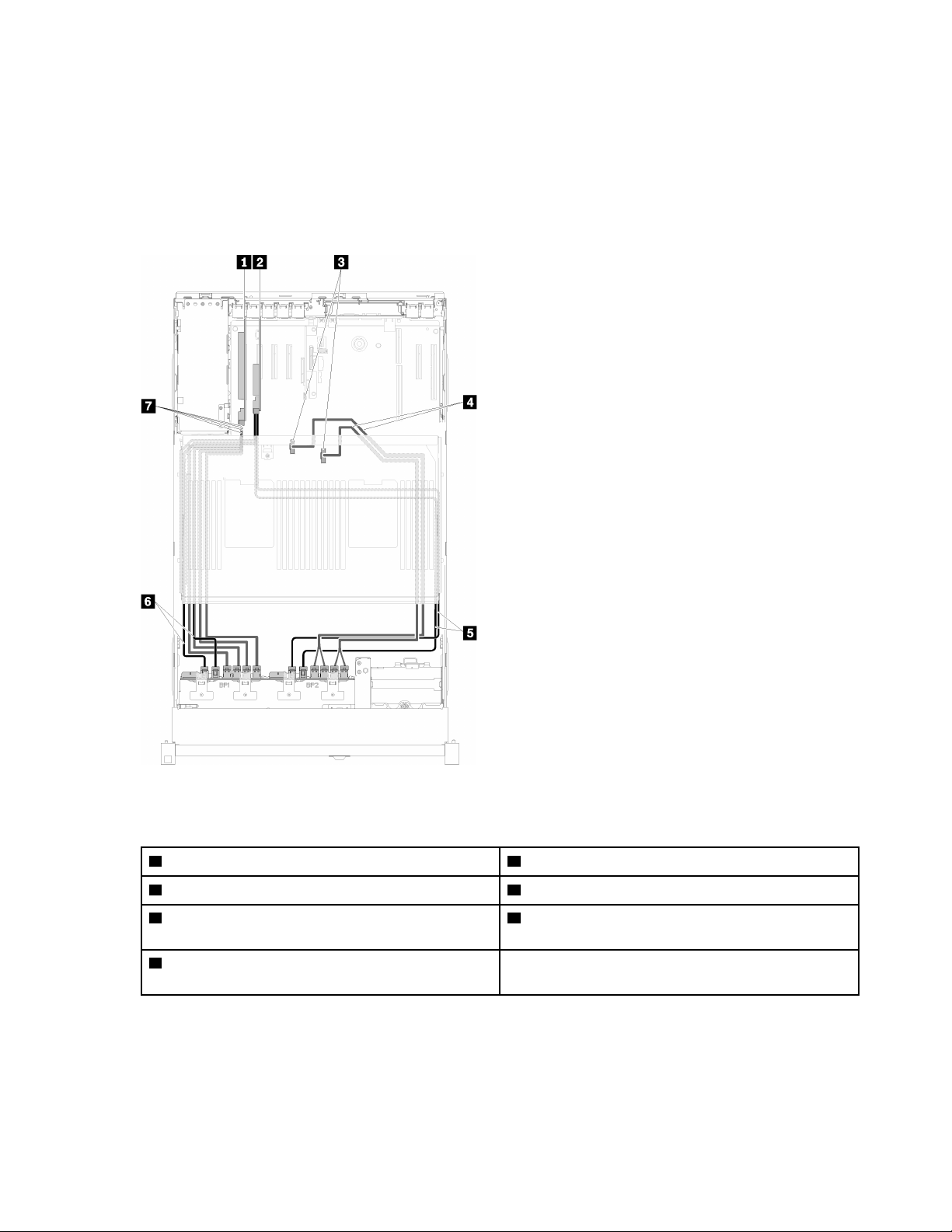
Four processors installed
Four options are available for this combination:
Note: Install the processor and memory expansion tray before connecting the signal cables to NVMe
connector on the expansion tray.
1. With SATA/SAS RAID adapter (16i)
Figure 39. Cable routing, AnyBay backplane + AnyBay backplane
Table 32. Cables and adapters for routing
1 PCIe switch card 5 SATA/SAS signal cables (900 mm)
2 SATA/SAS RAID adapter (16i) 6 SATA/SAS signal cables (720 mm)
3 NVMe connectors on the processor and memory
7 NVMe signal cables for PCIe switch card
expansion tray
4 Direct NVMe signal cables for processor and
memory expansion tray
Chapter 2. Server components 49
Page 58
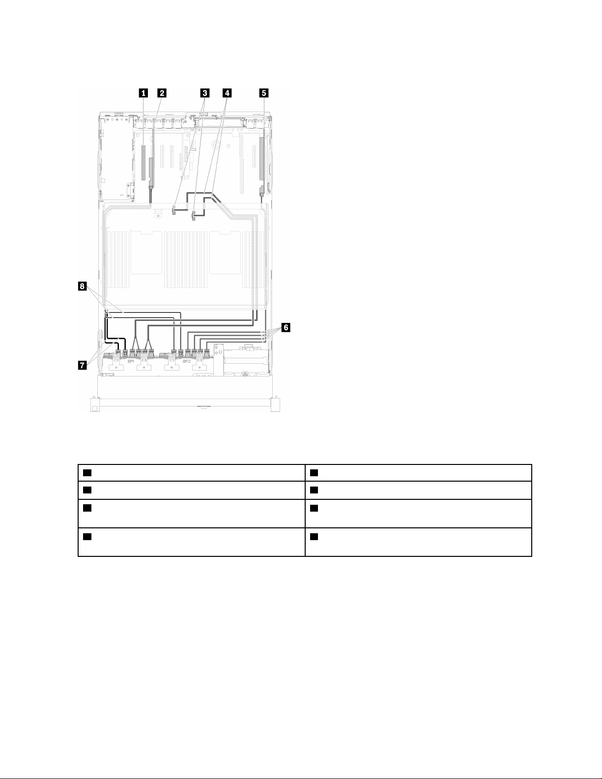
2. With SATA/SAS RAID adapter (16i)
Figure 40. Cable routing, AnyBay backplane + AnyBay backplane
Table 33. Cables and adapters for routing
1 4U PCIe riser card 5 PCIe switch card
2 SATA/SAS RAID adapter (16i) 6 NVMe signal cables for PCIe switch card
3 NVMe connectors on the processor and memory
7 SATA/SAS signal cables (720 mm)
expansion tray
4 Direct NVMe signal cables for processor and
8 SATA/SAS signal cables (900 mm)
memory expansion tray
50 ThinkSystem SR860 Setup Guide
Page 59
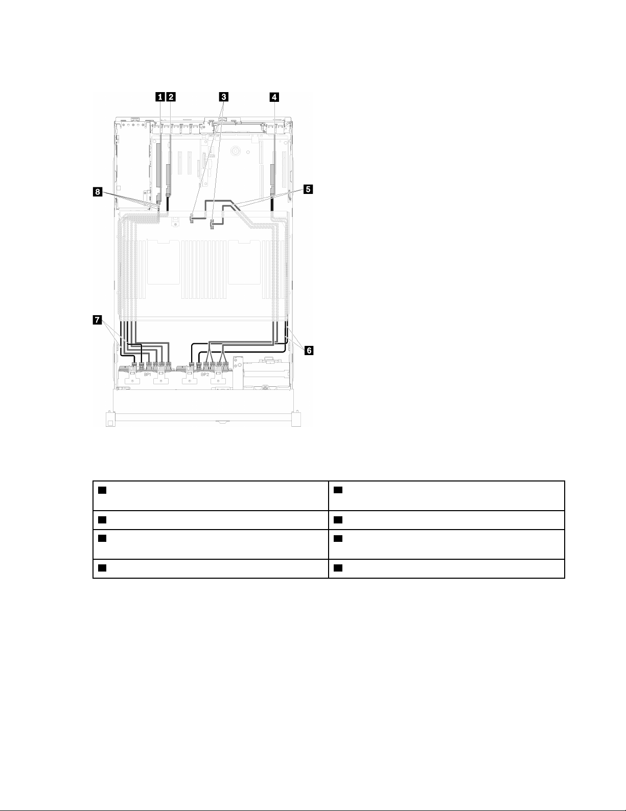
3. With SATA/SAS RAID adapter (8i)
Figure 41. Cable routing, AnyBay backplane + AnyBay backplane
Table 34. Cables and adapters for routing
1 PCIe switch card
5 Direct NVMe signal cables for processor and
memory expansion tray
2 SATA/SAS RAID adapter (8i) 6 SATA/SAS signal cables (720 mm)
3 NVMe connectors on the processor and memory
7 SATA/SAS signal cables (720 mm)
expansion tray
4 SATA/SAS RAID adapter (8i) 8 NVMe signal cables for PCIe switch card
Chapter 2. Server components 51
Page 60
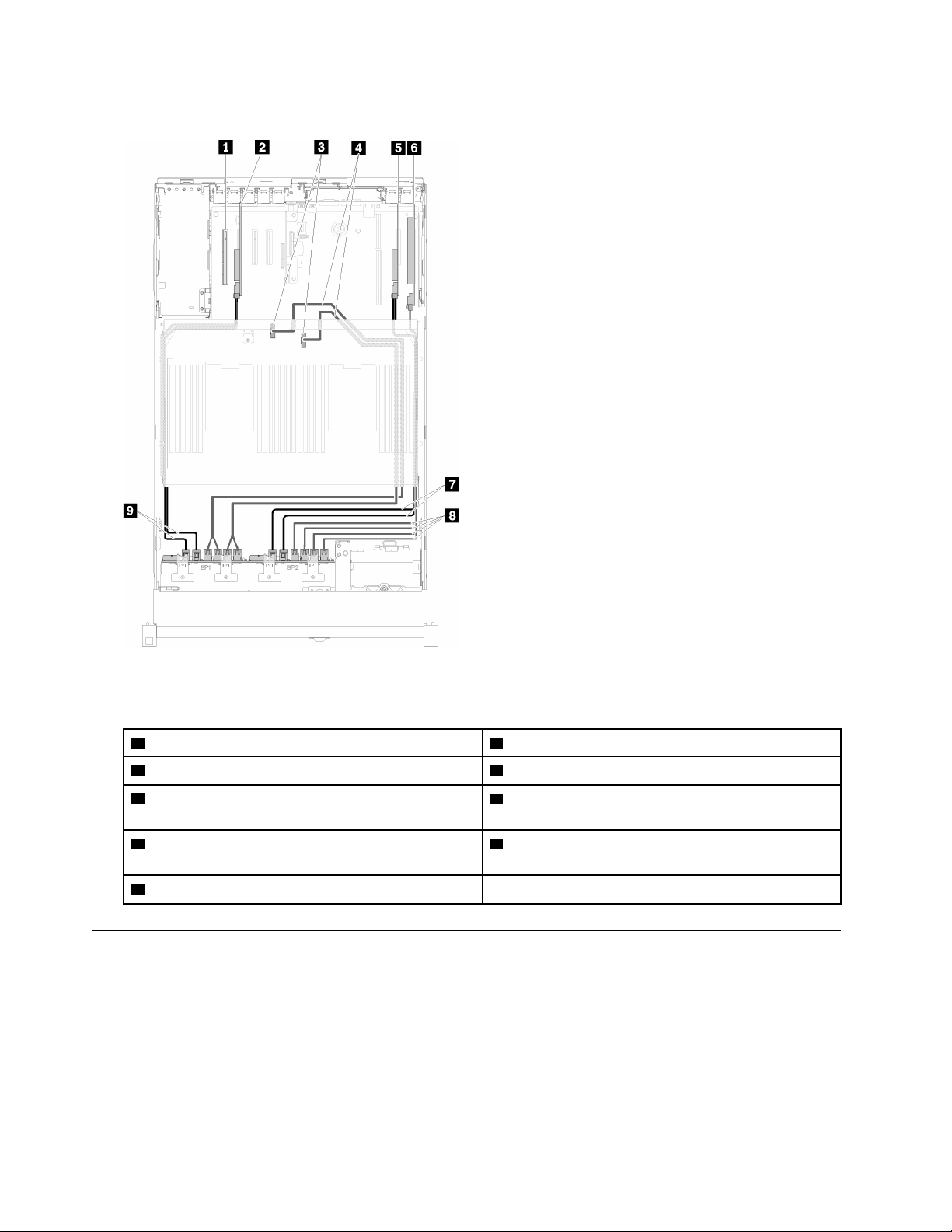
4. With SATA/SAS RAID adapter (8i)
Figure 42. Cable routing, AnyBay backplane + AnyBay backplane
Table 35. Cables and adapters for routing
1 4U PCIe riser card 6 PCIe switch card
2 SATA/SAS RAID adapter (8i) 7 SATA/SAS signal cables (720 mm)
3 NVMe connectors on the processor and memory
expansion tray
4 Direct NVMe signal cables for processor and
memory expansion tray
5 SATA/SAS RAID adapter (8i)
8 NVMe signal cables for PCIe switch card
9 SATA/SAS signal cables (720 mm)
Parts list
Use the parts list to identify each of the components that are available for your server.
For more information about ordering the parts shown in Figure 43 “Server components” on page 53:
https://datacentersupport.lenovo.com/products/servers/thinksystem/sr860
Note: Depending on the model, your server might look slightly different from the illustration.
52
ThinkSystem SR860 Setup Guide
Page 61
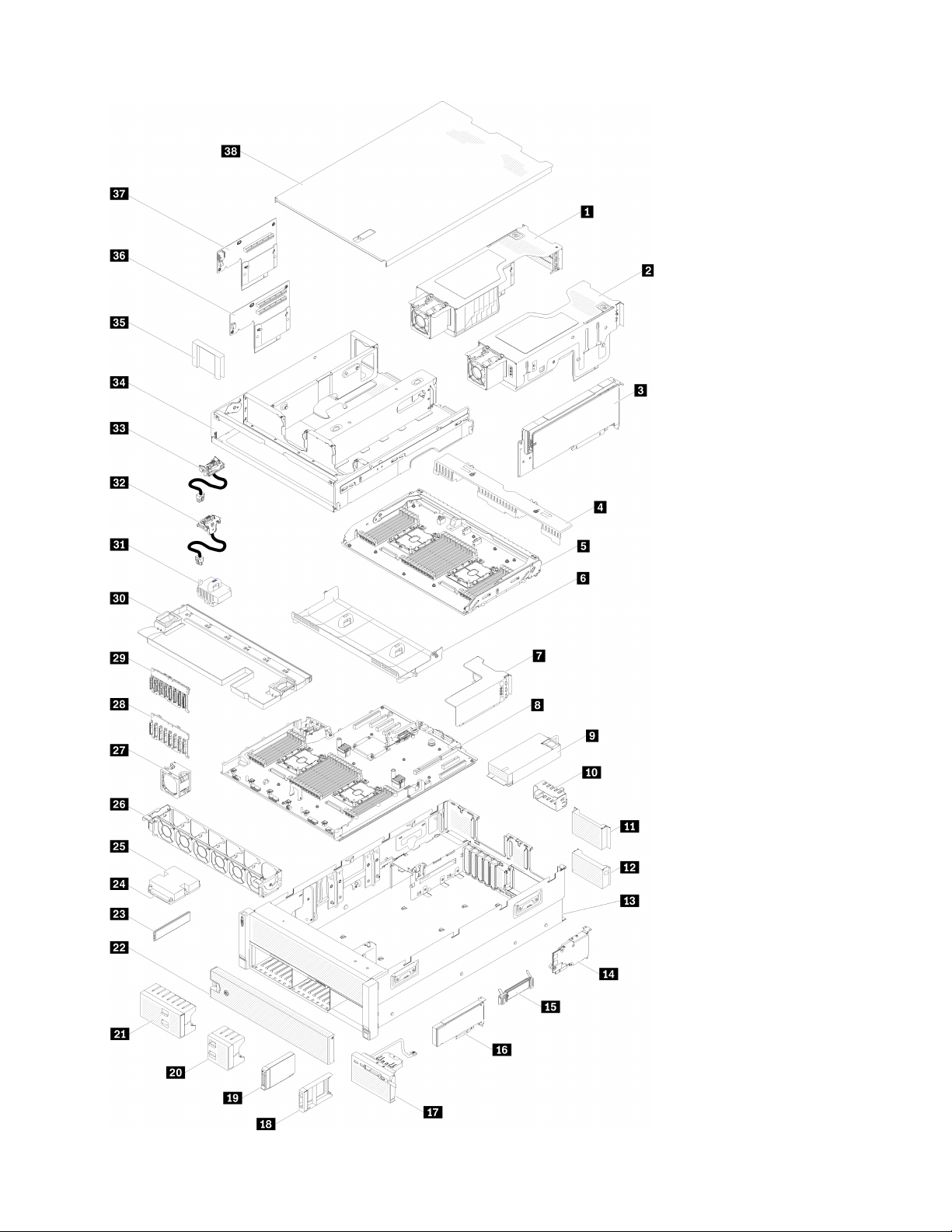
Chapter 2. Server components 53
Page 62
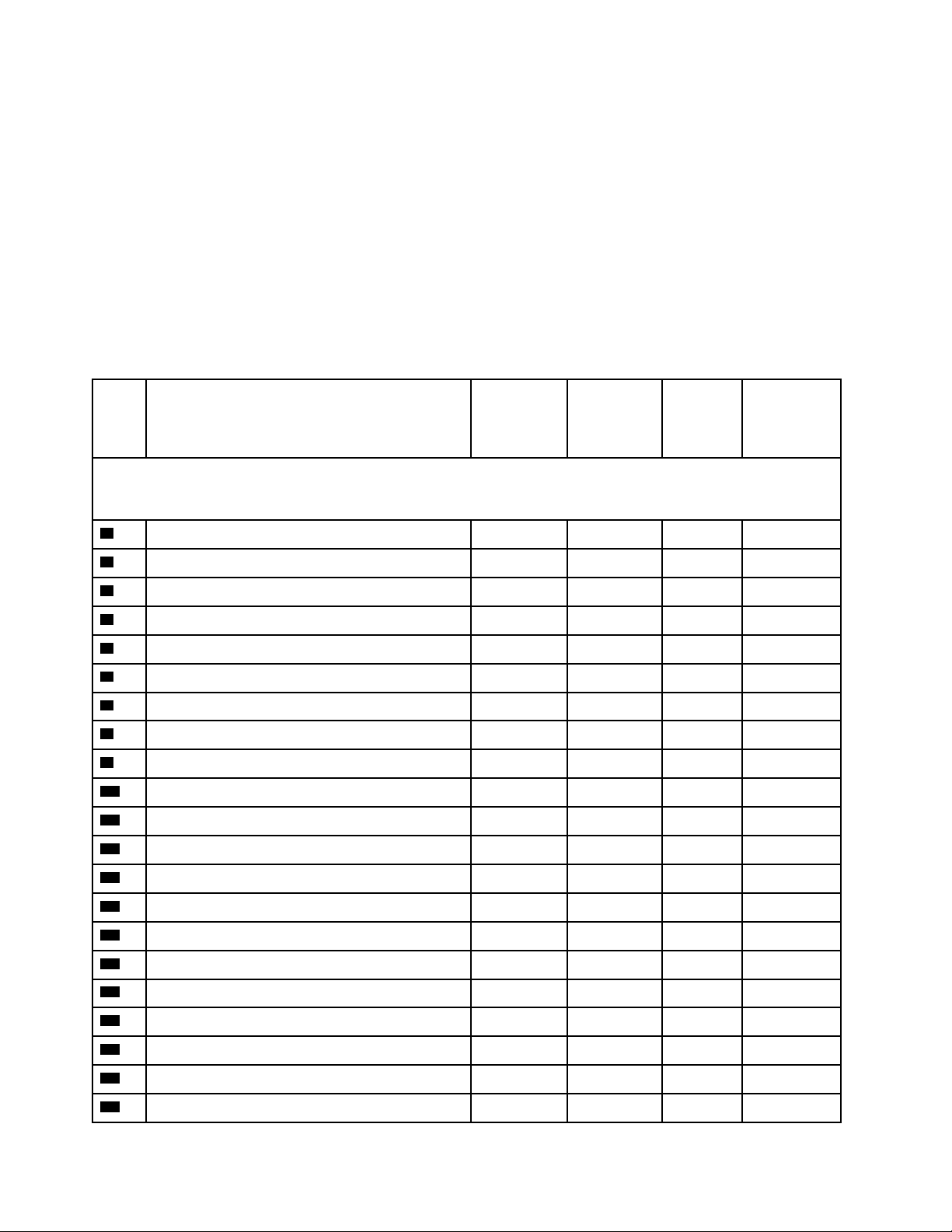
Figure 43. Server components
The parts listed in the following table are identified as one of the following:
• Tier 1 customer replaceable unit (CRU): Replacement of Tier 1 CRUs is your responsibility. If Lenovo
installs a Tier 1 CRU at your request with no service agreement, you will be charged for the installation.
• Tier 2 customer replaceable unit: You may install a Tier 2 CRU yourself or request Lenovo to install it, at
no additional charge, under the type of warranty service that is designated for your server.
• Field replaceable unit (FRU): FRUs must be installed only by trained service technicians.
• Consumable and Structural parts: Purchase and replacement of consumable and structural parts
(components, such as a cover or bezel) is your responsibility. If Lenovo acquires or installs a structural
component at your request, you will be charged for the service.
Table 36. Parts listing
Index Description Tier 1 CRU Tier 2 CRU FRU Consuma-
ble and
Structural
part
For more information about ordering the parts shown in Figure 43 “Server components” on page 53:
https://datacentersupport.lenovo.com/products/servers/thinksystem/sr860
1
2
3
4
5
6
7
8
9
10
11
12
13
14
15
16
17
18
19
20
21
4U PCIe riser cage 3
4U PCIe riser cage 2
PCIe adapter in 4U PCIe riser assembly
Processor and memory expansion tray air baffle
Processor and memory expansion tray
System board air baffle
PCIe riser card assembly
System board
Power supply unit
Power supply filler
4U PCIe riser assembly fillers
PCIe riser card filler
Chassis
LOM adapter
M.2 backplane
PCIe adapter
Operator panel tray assembly
2.5-inch drive filler
2.5-inch drive
2.5-inch drive 4-bay filler
2.5-inch drive 8-bay filler
√
√
√
√
√
√
√
√
√
√
√
√
√
√
√
√
√
√
√
√
√
54 ThinkSystem SR860 Setup Guide
Page 63
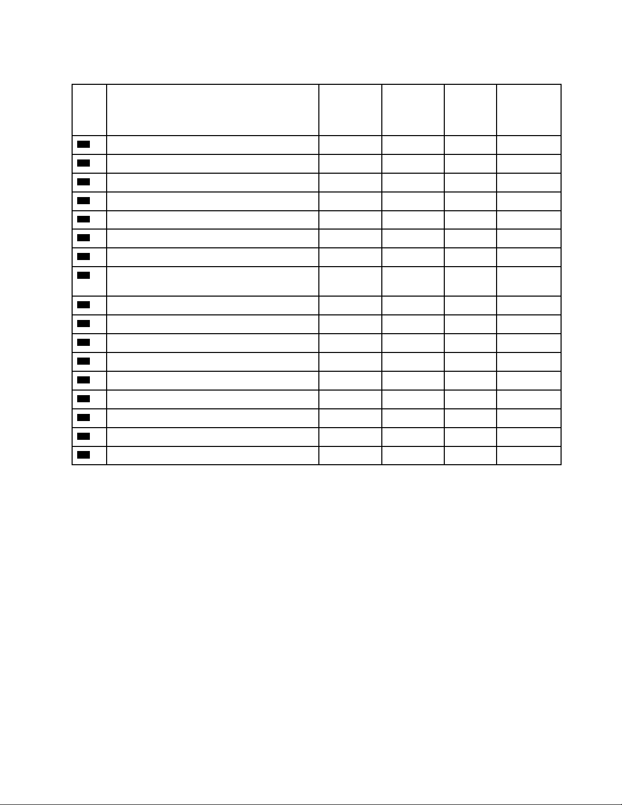
Table 36. Parts listing (continued)
Index Description
22
23
24
25
26
27
28
29
Security bezel
Memory module
Processor
Heatsink
Fan cage
Fan
2.5-inch SATA/SAS 8-bay backplane
2.5-inch AnyBay (SATA/SAS/NVMe) 8-bay
backplane
30
31
32
33
34
35
36
37
38
Chassis air baffle
Power interposer
4U PCIe riser 2 power cable assembly
4U PCIe riser 3 power cable assembly
PCIe expansion tray
4U PCIe riser assembly fillers
4U PCIe riser card x8
4U PCIe riser card x16
Top cover
Tier 1 CRU Tier 2 CRU
√
√
√
√
√
√
√
√
√
√
√
√
√
√
√
FRU
Consumable and
Structural
part
√
√
Chapter 2. Server components 55
Page 64

Power cords
Several power cords are available, depending on the country and region where the server is installed.
To view the power cords that are available for the server:
1. Go to:
http://lesc.lenovo.com
2. In the Customize a Model pane:
a. Click Select Options/Parts for a Model.
b. Enter the machine type and model for your server.
3. Click the Power tab to see all line cords.
Notes:
• For your safety, a power cord with a grounded attachment plug is provided to use with this product. To
avoid electrical shock, always use the power cord and plug with a properly grounded outlet.
• Power cords for this product that are used in the United States and Canada are listed by Underwriter's
Laboratories (UL) and certified by the Canadian Standards Association (CSA).
• For units intended to be operated at 115 volts: Use a UL-listed and CSA-certified cord set consisting of a
minimum 18 AWG, Type SVT or SJT, three-conductor cord, a maximum of 15 feet in length and a parallel
blade, grounding-type attachment plug rated 15 amperes, 125 volts.
• For units intended to be operated at 230 volts (U.S. use): Use a UL-listed and CSA-certified cord set
consisting of a minimum 18 AWG, Type SVT or SJT, three-conductor cord, a maximum of 15 feet in length
and a tandem blade, grounding-type attachment plug rated 15 amperes, 250 volts.
• For units intended to be operated at 230 volts (outside the U.S.): Use a cord set with a grounding-type
attachment plug. The cord set should have the appropriate safety approvals for the country in which the
equipment will be installed.
• Power cords for a specific country or region are usually available only in that country or region.
56
ThinkSystem SR860 Setup Guide
Page 65

Chapter 3. Server hardware setup
To set up the server, install any options that have been purchased, cable the server, configure and update
the firmware, and install the operating system.
Server setup checklist
Use the server setup checklist to ensure that you have performed all tasks that are required to set up your
server.
The server setup procedure varies depending on the configuration of the server when it was delivered. In
some cases, the server is fully configured and you just need to connect the server to the network and an ac
power source, and then you can power on the server. In other cases, the server needs to have hardware
options installed, requires hardware and firmware configuration, and requires an operating system to be
installed.
The following steps describe the general procedure for setting up a server:
1. Unpack the server package. See “Server package contents” on page 1.
2. Set up the server hardware.
a. Install any required hardware or server options. See the related topics in “Install server hardware
options” on page 60.
b. If necessary, install the server into a standard rack cabinet by using the rail kit shipped with the
server. See the Rack Installation Instructions that comes with optional rail kit.
c. Connect the Ethernet cables and power cords to the server. See “Rear view” on page 23 to locate
the connectors. See “Cable the server” on page 100 for cabling best practices.
d. Power on the server. See “Power on the server” on page 100.
Note: You can access the management processor interface to configure the system without
powering on the server. Whenever the server is connected to power, the management processor
interface is available. For details about accessing the management server processor, see:
http://sysmgt.lenovofiles.com/help/topic/com.lenovo.systems.management.xcc.doc/dw1lm_c_
chapter2_openingandusing.html
e. Validate that the server hardware was set up successfully. See Validate server setup.
3. Configure the system.
a. Connect the Lenovo XClarity Controller to the management network. See Set the network connection
for the Lenovo XClarity Controller.
b. Update the firmware for the server, if necessary. See “Update the firmware” on page 104.
c. Configure the firmware for the server. See “Configure the firmware” on page 107.
The following information is available for RAID configuration:
• https://lenovopress.com/lp0578-lenovo-raid-introduction
• https://lenovopress.com/lp0579-lenovo-raid-management-tools-and-resources
d. Install the operating system. See “Install the operating system” on page 109.
e. Back up the server configuration. See “Back up the server configuration” on page 109.
f. Install the applications and programs for which the server is intended to be used.
© Copyright Lenovo 2017 57
Page 66

Installation Guidelines
Use the installation guidelines to install components in your server.
Before installing optional devices, read the following notices carefully:
Attention: Prevent exposure to static electricity, which might lead to system halt and loss of data, by
keeping static-sensitive components in their static-protective packages until installation, and handling these
devices with an electrostatic-discharge wrist strap or other grounding system.
• Read the safety information and guidelines to ensure that you work safely.
– A complete list of safety information for all products is available at:
http://thinksystem.lenovofiles.com/help/topic/safety_documentation/pdf_files.html
– The following guidelines are available as well: “Handling static-sensitive devices” on page 59
• Make sure the components you are installing are supported by the server. For a list of supported optional
components for the server, see http://www.lenovo.com/serverproven/.
• When you install a new server, download and apply the latest firmware. This will help ensure that any
known issues are addressed, and that your server is ready to work with optimal performance. Go to
ThinkSystem SR860 Drivers and Software to download firmware updates for your server.
Important: Some cluster solutions require specific code levels or coordinated code updates. If the
component is part of a cluster solution, verify that the latest level of code is supported for the cluster
solution before you update the code.
• It is good practice to make sure that the server is working correctly before you install an optional
component.
• Keep the working area clean, and place removed components on a flat and smooth surface that does not
shake or tilt.
• Do not attempt to lift an object that might be too heavy for you. If you have to lift a heavy object, read the
following precautions carefully:
– Make sure that you can stand steadily without slipping.
– Distribute the weight of the object equally between your feet.
– Use a slow lifting force. Never move suddenly or twist when you lift a heavy object.
– To avoid straining the muscles in your back, lift by standing or by pushing up with your leg muscles.
• Make sure that you have an adequate number of properly grounded electrical outlets for the server,
monitor, and other devices.
• Back up all important data before you make changes related to the disk drives.
• Have a small flat-blade screwdriver, a small Phillips screwdriver, and a T8 torx screwdriver available.
• To view the error LEDs on the system board and internal components, leave the power on.
• You do not have to turn off the server to remove or install hot-swap power supplies, hot-swap fans, or hotplug USB devices. However, you must turn off the server before you perform any steps that involve
removing or installing adapter cables, and you must disconnect the power source from the server before
you perform any steps that involve removing or installing a riser card.
• Blue on a component indicates touch points, where you can grip to remove a component from or install it
in the server, open or close a latch, and so on.
• Orange on a component or an orange label on or near a component indicates that the component can be
hot-swapped if the server and operating system support hot-swap capability, which means that you can
remove or install the component while the server is still running. (Orange can also indicate touch points on
58
ThinkSystem SR860 Setup Guide
Page 67

hot-swap components.) See the instructions for removing or installing a specific hot-swap component for
any additional procedures that you might have to perform before you remove or install the component.
• The Red strip on the drives, adjacent to the release latch, indicates that the drive can be hot-swapped if
the server and operating system support hot-swap capability. This means that you can remove or install
the drive while the server is still running.
Note: See the system specific instructions for removing or installing a hot-swap drive for any additional
procedures that you might need to perform before you remove or install the drive.
• After finishing working on the server, make sure you reinstall all safety shields, guards, labels, and ground
wires.
System reliability guidelines
Review the system reliability guidelines to ensure proper system cooling and reliability.
Make sure the following requirements are met:
• When the server comes with redundant power, a power supply must be installed in each power-supply
bay.
• Adequate space around the server must be spared to allow server cooling system to work properly. Leave
approximately 50 mm (2.0 in.) of open space around the front and rear of the server. Do not place any
object in front of the fans.
• For proper cooling and airflow, refit the server cover before you turn the power on. Do not operate the
server for more than 30 minutes with the server cover removed, for it might damage server components.
• Cabling instructions that come with optional components must be followed.
• A failed fan must be replaced within 48 hours since malfunction.
• A removed hot-swap fan must be replaced within 30 seconds after removal.
• A removed hot-swap drive must be replaced within two minutes after removal.
• A removed hot-swap power supply must be replaced within two minutes after removal.
• Every air baffle that comes with the server must be installed when the server starts (some servers might
come with more than one air baffle). Operating the server with a missing air baffle might damage the
processor.
• All processor sockets must contain either a socket cover or a processor with heat sink.
• When more than one processor is installed, fan population rules for each server must be strictly followed.
Handling static-sensitive devices
Use this information to handle static-sensitive devices.
Attention: Prevent exposure to static electricity, which might lead to system halt and loss of data, by
keeping static-sensitive components in their static-protective packages until installation, and handling these
devices with an electrostatic-discharge wrist strap or other grounding system.
• Limit your movement to prevent building up static electricity around you.
• Take additional care when handling devices during cold weather, for heating would reduce indoor
humidity and increase static electricity.
• Always use an electrostatic-discharge wrist strap or other grounding system, particularly when working
inside the server with the power on.
• While the device is still in its static-protective package, touch it to an unpainted metal surface on the
outside of the server for at least two seconds. This drains static electricity from the package and from your
body.
Chapter 3. Server hardware setup 59
Page 68

• Remove the device from the package and install it directly into the server without putting it down. If it is
necessary to put the device down, put it back into the static-protective package. Never place the device
on the server or on any metal surface.
• When handling a device, carefully hold it by the edges or the frame.
• Do not touch solder joints, pins, or exposed circuitry.
• Keep the device from others’ reach to prevent possible damages.
Install server hardware options
This section includes instructions for performing initial installation of optional hardware. Each component
installation procedure references any tasks that need to be performed to gain access to the component
being replaced.
Installation procedures are presented in the optimum sequence to minimize work.
Attention: To ensure the components you install work correctly without problems, read the following
precautions carefully.
• Make sure the components you are installing are supported by the server. For a list of supported optional
components for the server, see http://www.lenovo.com/serverproven/.
• Always download and apply the latest firmware. This will help ensure that any known issues are
addressed, and that your server is ready to work with optimal performance. Go to ThinkSystem SR860
Drivers and Software to download firmware updates for your server.
• It is good practice to make sure that the server is working correctly before you install an optional
component.
• Follow the installation procedures in this section and use appropriate tools. Incorrectly installed
components can cause system failure from damaged pins, damaged connectors, loose cabling, or loose
components.
Remove the security bezel
Use this procedure to remove the security bezel.
Before removing the security bezel:
1. Read the safety information and installation guidelines (see “Safety” on page iii and “Installation
Guidelines” on page 58).
2. If the server is installed in a rack, extend or remove the server from the rack.
To remove the security bezel, complete the following steps:
Step 1. Use the key to unlock the security bezel to the open position.
60
ThinkSystem SR860 Setup Guide
Page 69
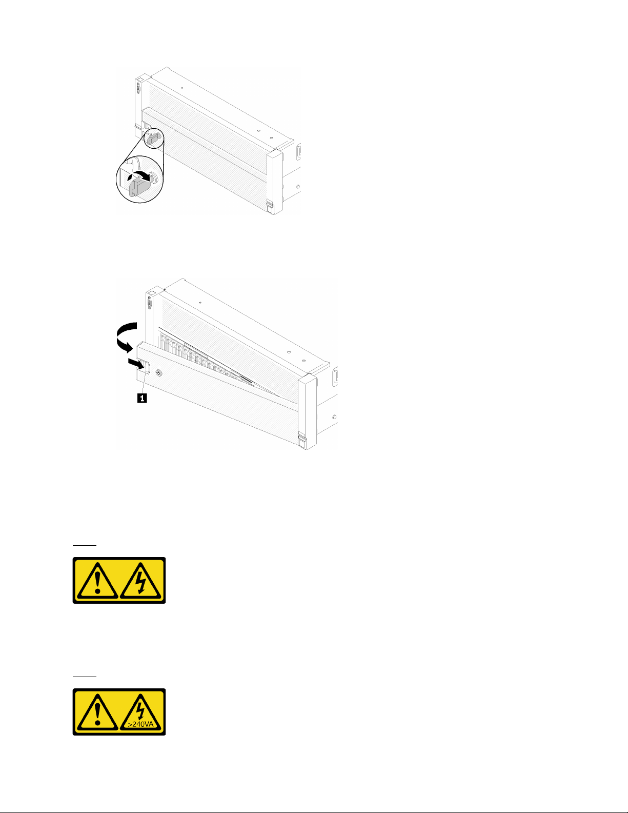
Figure 44. Unlocking the security bezel
Step 2. Press the release latch and pivot the security bezel outward to remove it from the chassis.
Figure 45. Security bezel removal
Remove the top cover
Use this procedure to remove the top cover.
S014
CAUTION:
Hazardous voltage, current, and energy levels might be present. Only a qualified service technician is
authorized to remove the covers where the following label is attached.
S033
Chapter 3. Server hardware setup 61
Page 70
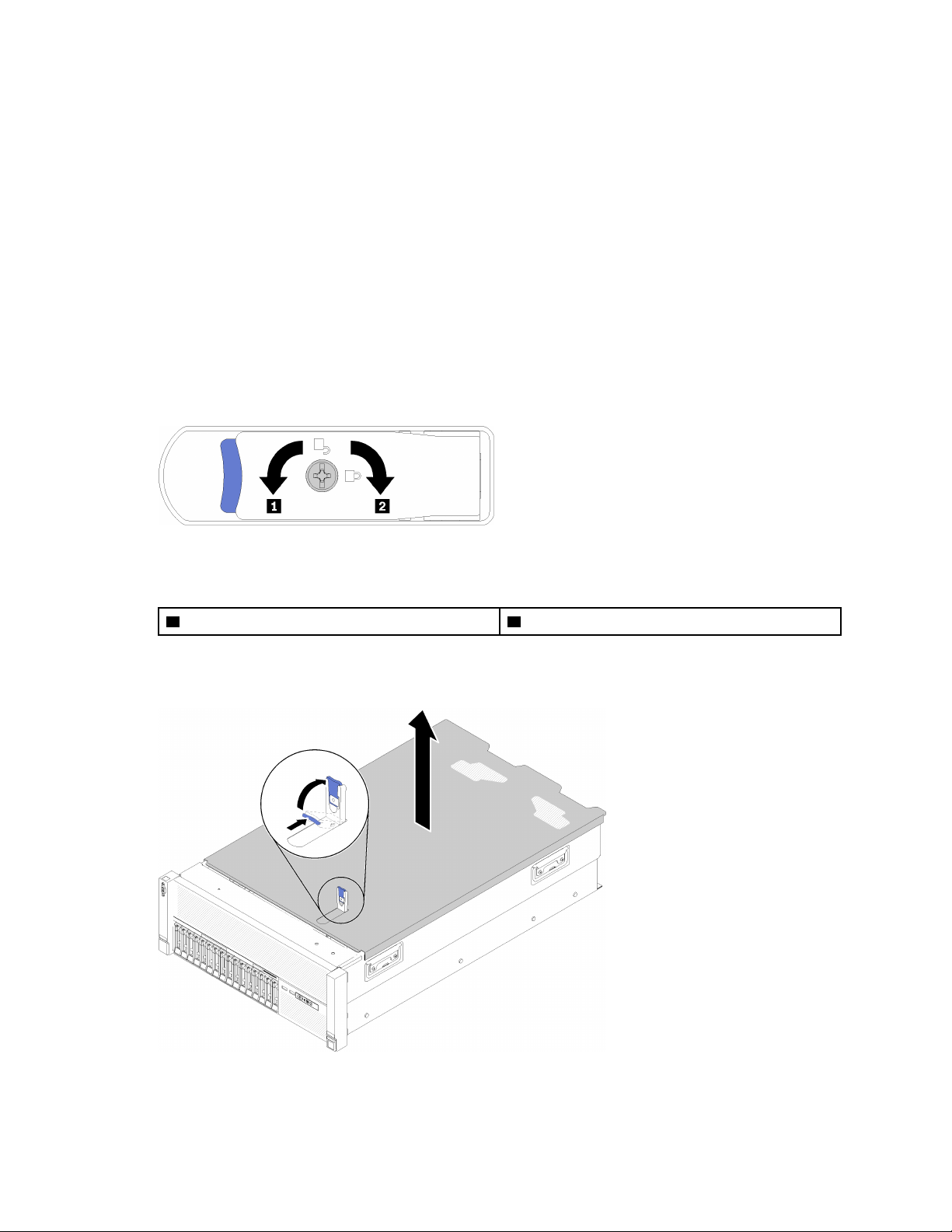
CAUTION:
Hazardous energy present. Voltages with hazardous energy might cause heating when shorted with
metal, which might result in spattered metal, burns, or both.
Before removing the top cover:
1. Read the safety information and installation guidelines (see “Safety” on page iii and “Installation
Guidelines” on page 58).
2. Turn off the server and peripheral devices and disconnect the power cords and all external cables (see
“Power off the server” on page 101).
3. If the server is installed in a rack, remove the server from the rack.
4. Remove the top cover (see “Remove the top cover” on page 61).
To remove the top cover, complete the following steps:
Step 1. Unlock the cover release latch with a flat-end screwdriver.
Figure 46. Lock on the top cover latch
Table 37. Lock/unlock directions on the top cover latch
1 Unlock 2 Lock
Step 2. Press and hold on the blue tab of cover release latch; then, rotate the tip of the latch up.
Step 3. Push the latch forward to slide the top cover away from the server.
Figure 47. Top cover removal
Step 4. Lift the cover, remove it from the server, and set it aside.
62
ThinkSystem SR860 Setup Guide
Page 71
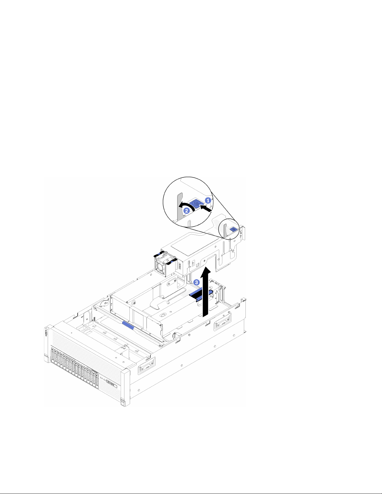
If you are instructed to return the component or optional device, follow all packaging instructions, and use
any packaging materials for shipping that are supplied to you.
Remove a 4U PCIe riser assembly
Use this procedure to remove a 4U PCIe riser assembly.
Before removing a 4U PCIe riser assembly:
1. Read the safety information and installation guidelines (see “Safety” on page iii and “Installation
Guidelines” on page 58).
2. Turn off the server and peripheral devices and disconnect the power cords and all external cables (see
“Power off the server” on page 101).
3. If the server is installed in a rack, remove the server from the rack.
4. Remove the top cover (see “Remove the top cover” on page 61).
To remove a 4U PCIe riser assembly, complete the following steps:
Figure 48. 4U PCIe riser assembly removal
Step 1. Open the release latch.
Step 2. Rotate the lever to disengage the 4U PCIe riser assembly from the slot.
Chapter 3. Server hardware setup 63
Page 72
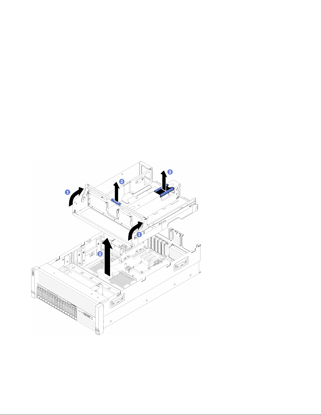
Step 3. Lift the 4U PCIe riser assembly out of the PCIe expansion tray.
If you are instructed to return the component or optional device, follow all packaging instructions, and use
any packaging materials for shipping that are supplied to you.
Remove the PCIe expansion tray
Use this procedure to remove the PCIe expansion tray.
Before removing the PCIe expansion tray:
1. Read the safety information and installation guidelines (see “Safety” on page iii and “Installation
Guidelines” on page 58).
2. Turn off the server and peripheral devices and disconnect the power cords and all external cables (see
“Power off the server” on page 101).
3. If the server is installed in a rack, remove the server from the rack.
4. Remove the top cover (see “Remove the top cover” on page 61).
To remove the PCIe expansion tray, complete the following steps:
Figure 49. PCIe expansion tray removal
Step 1. Remove all the 4U PCIe riser assemblies and the 4U PCIe riser assembly fillers that are installed in
the PCIe expansion tray (see “Remove a 4U PCIe riser assembly” on page 63).
Step 2. Grasp the handle of the PCIe expansion tray; then, rotate it upward to the vertical position.
64
ThinkSystem SR860 Setup Guide
Page 73
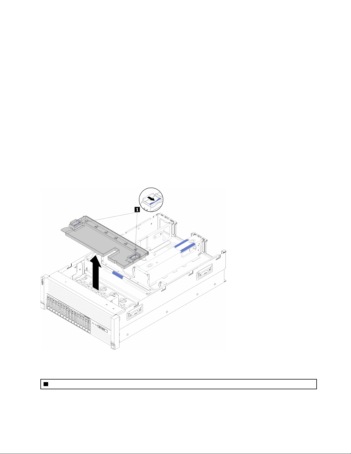
Step 3. Grasp the handle with one of your hands, with the other hand grasping the 4U PCIe expansion tray
lift point; then, lift the tray out of the server.
If you are instructed to return the component or optional device, follow all packaging instructions, and use
any packaging materials for shipping that are supplied to you.
Remove the chassis air baffle
Use this procedure to remove the chassis air baffle.
Before removing the chassis air baffle:
1. Read the safety information and installation guidelines (see “Safety” on page iii and “Installation
Guidelines” on page 58).
2. Turn off the server and peripheral devices and disconnect the power cords and all external cables (see
“Power off the server” on page 101).
3. If the server is installed in a rack, remove the server from the rack.
4. Remove the top cover (see “Remove the top cover” on page 61).
To remove the chassis air baffle, complete the following steps:
Figure 50. Chassis air baffle removal
Table 38. Chassis air baffle release latch
1 Release latches
Step 1. Press the chassis air baffle release latches; then, lift the chassis air baffle out from the server.
Chapter 3. Server hardware setup 65
Page 74
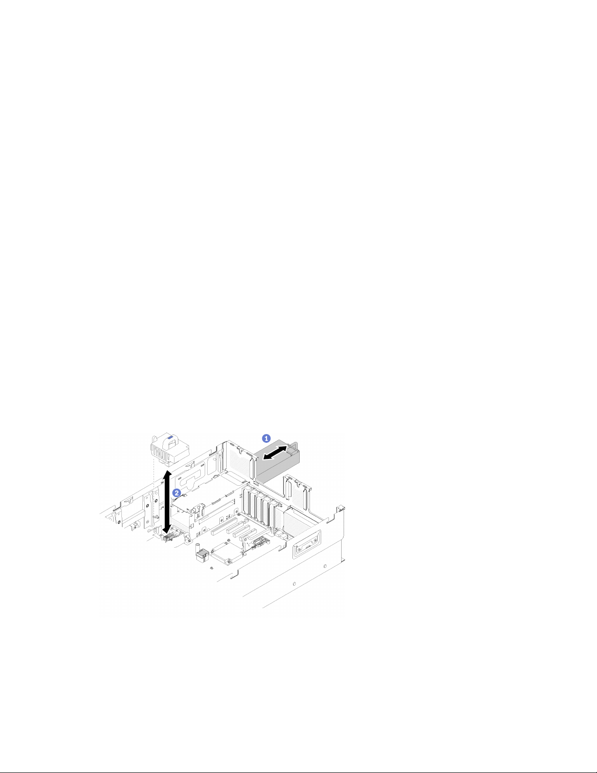
Note: For proper cooling and airflow, reinstall the chassis air baffle before you install the server into
the rack. Operating the server with the chassis air baffle removed might damage server
components.
If you are instructed to return the component or optional device, follow all packaging instructions, and use
any packaging materials for shipping that are supplied to you.
Remove the system board air baffle and the power interposer
Use this procedure to remove the system board air baffle and the power interposer.
Note: If the server comes with a processor and memory expansion tray, it does not come with this
component.
Before removing the system board air baffle, complete the following steps:
1. Read the safety information and installation guidelines (see “Safety” on page iii and “Installation
Guidelines” on page 58).
2. Turn off the server and peripheral devices and disconnect the power cords and all external cables (see
“Power off the server” on page 101).
3. If the server is installed in a rack, remove the server from the rack.
4. Remove the top cover (see “Remove the top cover” on page 61).
5. Remove the PCIe expansion tray (see “Remove the PCIe expansion tray” on page 64).
To remove the system board air baffle, complete the following steps:
Step 1. Slightly slide power supply 2 out from the power supply bay (see “Remove a hot-swap power
supply unit” in ThinkSystem SR860 Maintenance Manual).
Step 2. Lift the power interposer from the server, and set it aside.
Figure 51. Power interposer removal
Step 3. Lift the system board air baffle from the server, and set it aside.
Attention: Air baffle is required for airflow that creates proper cooling. Make sure proper air baffle
(s) for system configuration is installed before the power is turned on.
66
ThinkSystem SR860 Setup Guide
Page 75
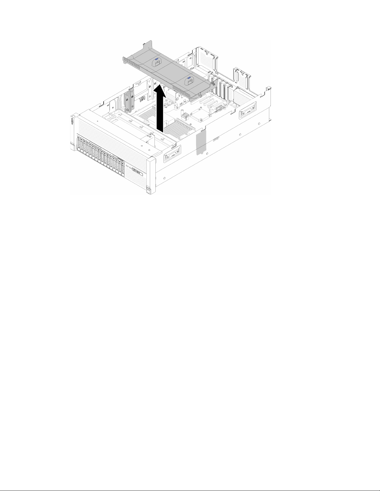
Figure 52. System board air baffle removal
If you are instructed to return the component or optional device, follow all packaging instructions, and use
any packaging materials for shipping that are supplied to you.
Remove the processor and memory expansion tray
Use this procedure to remove the processor and memory expansion tray.
Before removing the processor and memory expansion tray:
1. Read the safety information and installation guidelines (see “Safety” on page iii and “Installation
Guidelines” on page 58).
2. Turn off the server and peripheral devices and disconnect the power cords and all external cables (see
“Power off the server” on page 101).
3. If the server is installed in a rack, remove the server from the rack.
4. Remove the top cover (see “Remove the top cover” on page 61).
5. Remove the PCIe expansion tray (see “Remove the PCIe expansion tray” on page 64).
6. If you are replacing the processor and memory expansion tray, remove the processor and memory
expansion tray air baffle, DIMMs (see Remove a DIMM), and PHMs (see “Remove a processor and the
heatsink” in ThinkSystem SR860 Maintenance Manual) on the expansion tray.
Chapter 3. Server hardware setup 67
Page 76
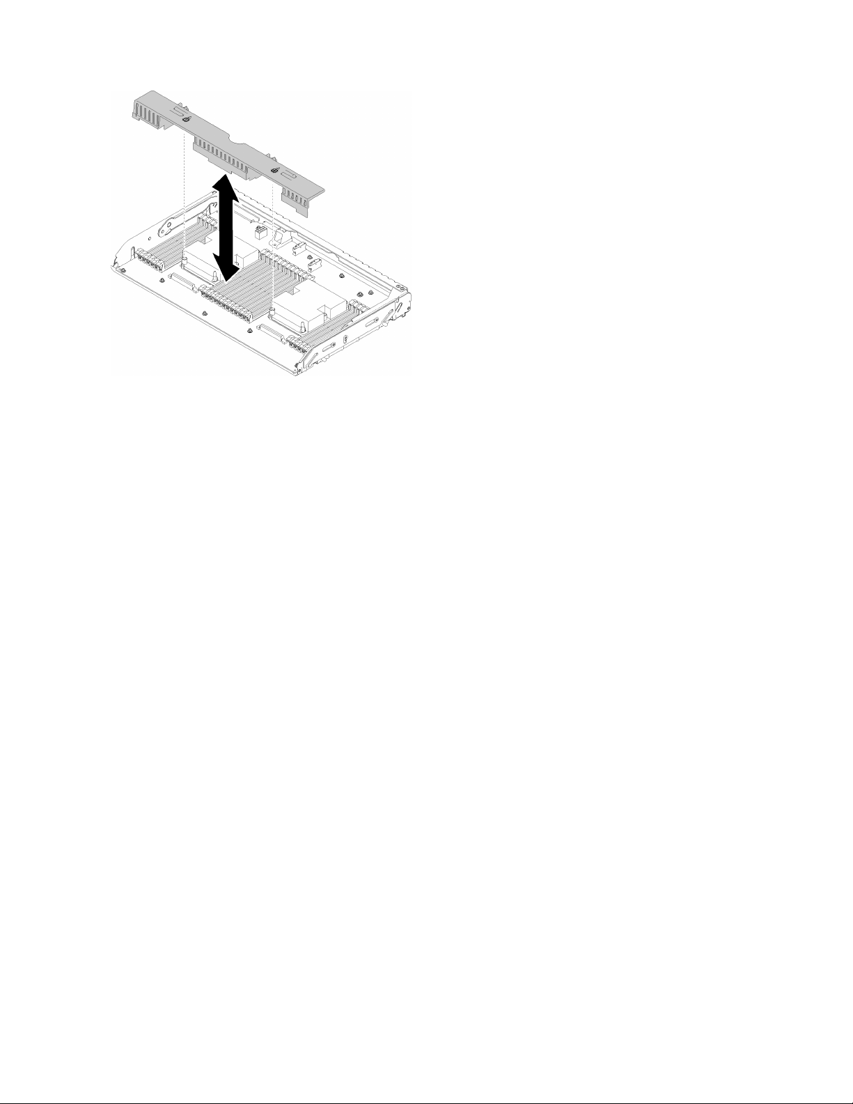
Figure 53. Processor and memory expansion tray air baffle removal
Attention: Do not remove or install DIMMs and processors on the processor and memory expansion
tray when the expansion tray is removed, for the instability might cause damages to components.
To remove the processor and memory expansion tray, complete the following steps:
Step 1. Disconnect all cables connected to the processor and memory expansion tray.
Step 2. Slightly pull out power supply 2.
Attention: Do not remove the processor and memory expansion tray without physically
disconnecting power supply 2.
Step 3. Grasp the handle of the processor and memory expansion tray; then, pull and rotate it upward to
the vertical position. This disengages the expansion tray from the system board.
Step 4. Grasp the handle and slowly lift the expansion tray from the server; then, set it on a flat surface.
68
ThinkSystem SR860 Setup Guide
Page 77
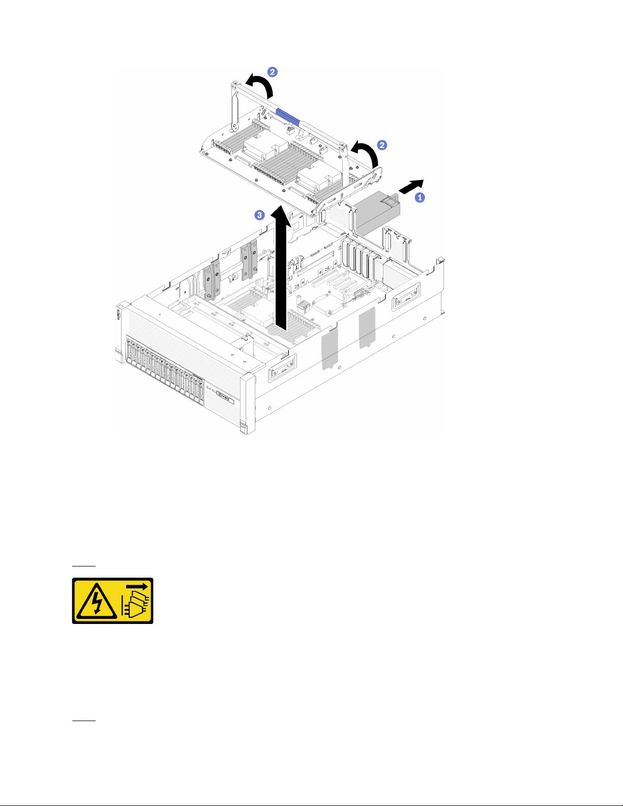
Figure 54. Processor and memory expansion tray removal
If you are instructed to return the component or optional device, follow all packaging instructions, and use
any packaging materials for shipping that are supplied to you.
Remove the fan cage assembly
Use this procedure to remove the fan cage assembly.
S002
CAUTION:
The power control button on the device and the power switch on the power supply do not turn off the
electrical current that is supplied to the device. The device also might have more than one power
cord. To remove all electrical current from the device, ensure that all power cords are disconnected
from the power source.
S017
Chapter 3. Server hardware setup 69
Page 78
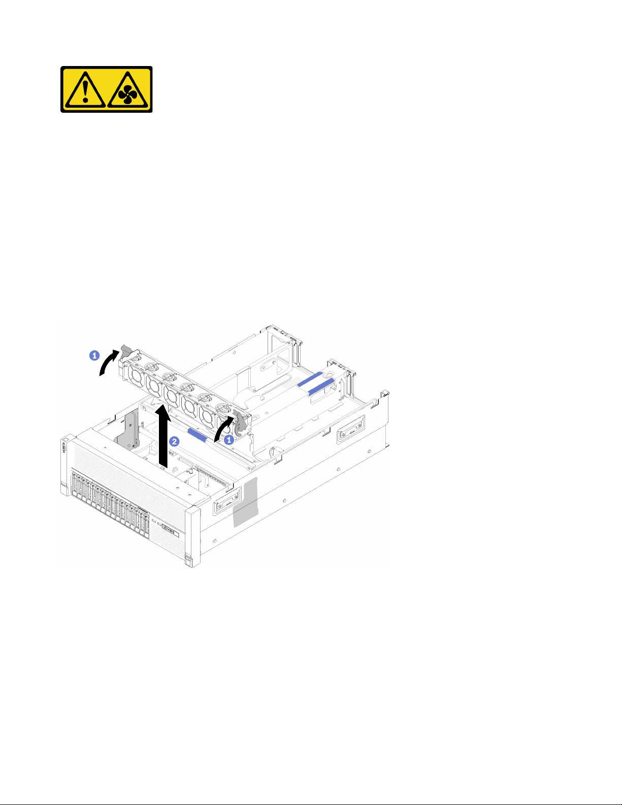
CAUTION:
Hazardous moving fan blades nearby.
Before removing the fan cage assembly:
1. Read the safety information and installation guidelines (see “Safety” on page iii and “Installation
Guidelines” on page 58).
2. Turn off the server and peripheral devices and disconnect the power cords and all external cables (see
“Power off the server” on page 101).
3. If the server is installed in a rack, remove the server from the rack.
4. Remove the top cover (see “Remove the top cover” on page 61).
5. Remove the chassis air baffle (see “Remove the chassis air baffle” on page 65).
To remove the fan cage assembly, complete the following steps:
Figure 55. Fan cage assembly removal
Step 1. Lift and rotate the fan cage release latches to disengage the fan cage assembly from the server.
Step 2. Lift the fan cage assembly from the server.
If you are instructed to return the component or optional device, follow all packaging instructions, and use
any packaging materials for shipping that are supplied to you.
70
ThinkSystem SR860 Setup Guide
Page 79
Install a processor-heat-sink module
Processors are in the compute system boards that are accessed from the front of the server. The processor
and heat sink are removed together as part of a processor-heat-sink-module (PHM) assembly. PHM
installation requires a Torx T30 driver.
Note: If you are installing multiple options relating to the compute system board, the PHM installation should
be performed first.
“Read the
installation
Guidelines” on
page 58
“Power off
the server
for this task”
on page 101
“ATTENTION:
Static Sensitive Device
Ground package before opening”
on page 59
Attention:
• Each processor socket must always contain a cover or a PHM. When removing or installing a PHM,
protect empty processor sockets with a cover.
• Do not touch the processor socket or processor contacts. Processor-socket contacts are very fragile and
easily damaged. Contaminants on the processor contacts, such as oil from your skin, can cause
connection failures.
• Remove and install only one PHM at a time. If the system board supports multiple processors, install the
PHMs starting with the first processor socket.
• Do not allow the thermal grease on the processor or heat sink to come in contact with anything. Contact
with any surface can compromise the thermal grease, rendering it ineffective. Thermal grease can damage
components, such as electrical connectors in the processor socket. Do not remove the grease cover from
a heat sink until you are instructed to do so.
Notes:
• PHMs are keyed for the socket where they can be installed and for their orientation in the socket.
• See http://www.lenovo.com/serverproven/ for a list of processors supported for your server. All
processors on the system board must have the same speed, number of cores, and frequency.
• Before you install a new PHM or replacement processor, update your system firmware to the latest level.
See “Update the firmware” on page 104.
• Installing an additional PHM can change the memory requirements for your system. See ThinkSystem
SR860 Memory Population Reference for a list of processor-to-memory relationships.
• Optional devices available for your system might have specific processor requirements. See the
documentation that comes with the optional device for information.
Before installing a PHM:
Note: The PHM for your system might be different than the PHM shown in the illustrations.
1. If the server is installed in a rack, remove the server from the rack.
2. Touch the static-protective package that contains the component to any unpainted metal surface on the
server; then, remove it from the package and place it on a static-protective surface.
3. Remove the top cover (see “Remove the top cover” on page 61).
4. Remove the system board air baffle (see “Remove the system board air baffle and the power interposer”
on page 66) or the processor and memory expansion tray and the processor and memory expansion tray
air baffle (see “Remove the processor and memory expansion tray” on page 67).
Chapter 3. Server hardware setup 71
Page 80
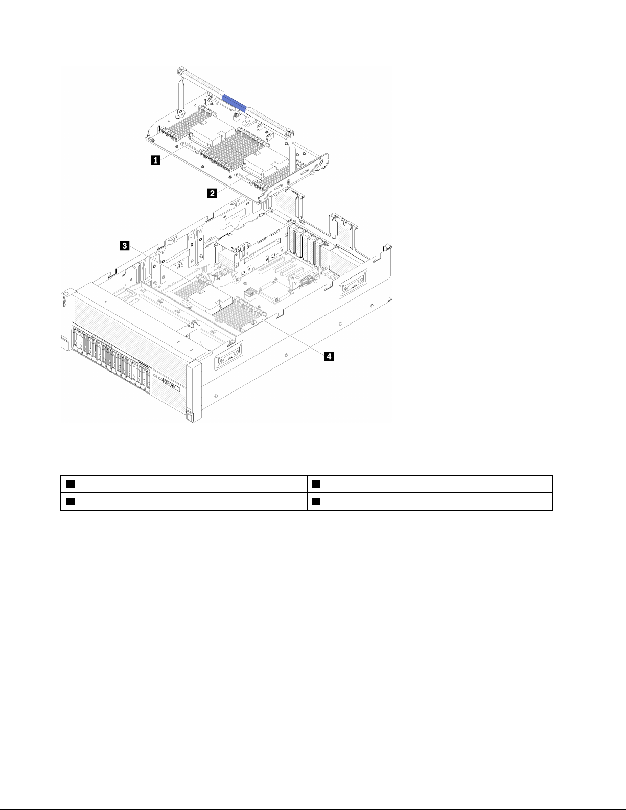
Figure 56. Processor locations
Table 39. Processor locations
1 Processor 3 3 Processor 1
2 Processor 4 4 Processor 2
Complete the following steps to install a PHM.
Step 1. Remove the processor socket cover, if one is installed on the processor socket, by placing your
fingers in the half-circles at each end of the cover and lifting it from the system board.
Step 2. Install the processor-heat-sink module on the system board.
72
ThinkSystem SR860 Setup Guide
Page 81
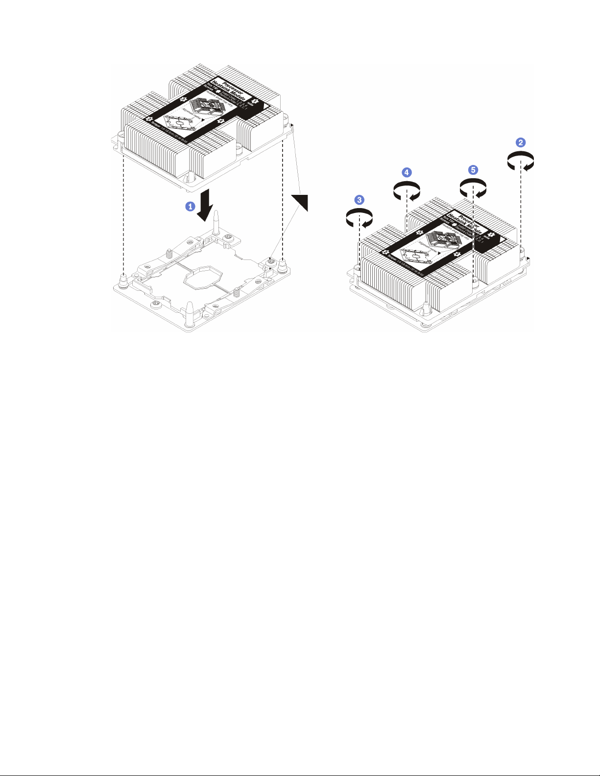
Figure 57. Installing a PHM
a. Align the triangular marks and guide pins on the processor socket with the PHM; then, insert
the PHM into the processor socket.
Attention: To prevent damage to components, make sure that you follow the indicated
tightening sequence.
b. Fully tighten the Torx T30 captive fasteners in the installation sequence shown on the heat-sink
label. Tighten the screws until they stop; then, visually inspect to make sure that there is no
gap between the screw shoulder beneath the heat sink and the processor socket. (For
reference, the torque required for the nuts to fully tighten is 1.4 — 1.6 newton-meters, 12 — 14
inch-pounds).
After installing the PHM option:
1. If there are memory modules to install, install them. See “Install a memory module” on page 74.
2. Reinstall the system board air baffle (see “Install the system board air baffle and the power interposer”
on page 80) or processor and memory expansion tray and processor and memory expansion tray air
baffle (see “Install the processor and memory expansion tray ” on page 81).
3. Install the top cover (see “Install the top cover” on page 97).
4. Reconnect the power cords and any cables that you removed.
5. Power on the server and any peripheral devices.
Chapter 3. Server hardware setup 73
Page 82
Install a memory module
Memory modules are installed in the compute system boards that are accessed from the front of the server.
“ATTENTION:
Static Sensitive Device
Ground package before opening”
on page 59
Attention: Memory modules are sensitive to static discharge and require special handling. In addition to the
standard guidelines for “Handling static-sensitive devices” on page 59:
• Always wear an electrostatic-discharge strap when removing or installing memory modules. Electrostaticdischarge gloves can also be used.
• Never hold two or more memory modules together so that they touch. Do not stack memory modules
directly on top of each other during storage.
• Never touch the gold memory module connector contacts or allow these contacts to touch the outside of
the memory-module connector housing.
• Handle memory modules with care: never bend, twist, or drop a memory module.
Before installing a memory module, make sure that you understand the required installation order, depending
on whether you are implementing memory mirroring, memory rank sparing, or independent memory mode.
See ThinkSystem SR860 Memory Population Reference for the required installation order.
If you are installing an optional processor, install it before installing memory modules. See “Install a
processor-heat-sink module” on page 71
Before installing a memory module:
1. Read the safety information and installation guidelines (see “Safety” on page iii and “Installation
Guidelines” on page 58).
2. Touch the static-protective package that contains the component to any unpainted metal surface on the
server; then, remove it from the package and place it on a static-protective surface.
Complete the following steps to install a memory module:
Step 1. Open the memory module connector retaining clips. If a memory module is already installed in the
connector, remove it.
Step 2. Align the keys on the memory module that you are installing with the connector; then, insert the
memory module.
Step 3. Firmly press both ends of the memory module straight down into the connector until the retaining
clips snap into the locked position.
74
ThinkSystem SR860 Setup Guide
Page 83
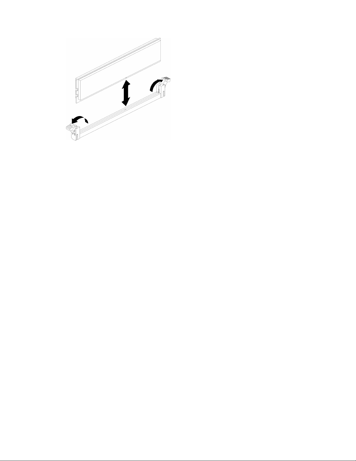
Figure 58. Memory module installation
Step 4. If you are installing additional memory modules, do so now.
After installing a memory module option:
1. Reinstall the system board air baffle (see “Install the system board air baffle and the power interposer”
on page 80) or processor and memory expansion tray and processor and memory expansion tray air
baffle (see “Install the processor and memory expansion tray ” on page 81).
2. Install the top cover (see “Install the top cover” on page 97).
3. Reconnect the power cords and any cables that you removed.
4. If the server is installed in a rack, reinstall the server into the rack.
5. Power on the server and any peripheral devices.
Install a drive backplane
Use this procedure to install a drive backplane.
Before installing a drive backplane:
1. Read the safety information and installation guidelines (see “Safety” on page iii and “Installation
Guidelines” on page 58).
2. Touch the static-protective package that contains the component to any unpainted metal surface on the
server; then, remove it from the package and place it on a static-protective surface.
To install a drive backplane, complete the following steps:
Step 1. Determine the location of the backplane to be installed accordingly to the following combinations.
For more details about drive bay numbering, see “Front view” on page 16.
• One drive backplane:
Always install the drive backplane to the drive bay 0-7 when there is only one backplane.
• Two drive backplanes:
Two types of drive backplanes are supported by this system:
– 2.5-inch SATA/SAS 8-bay backplane (referred to as “8-bay backplane”)
– 2.5-inch AnyBay 8-bay backplane (referred to as “AnyBay backplane”)
When installing a AnyBay backplane and a 8-bay backplane, always install the AnyBay
backplane to drive bay 0-7, and the 8-bay backplane to drive bay 8-15.
Chapter 3. Server hardware setup 75
Page 84
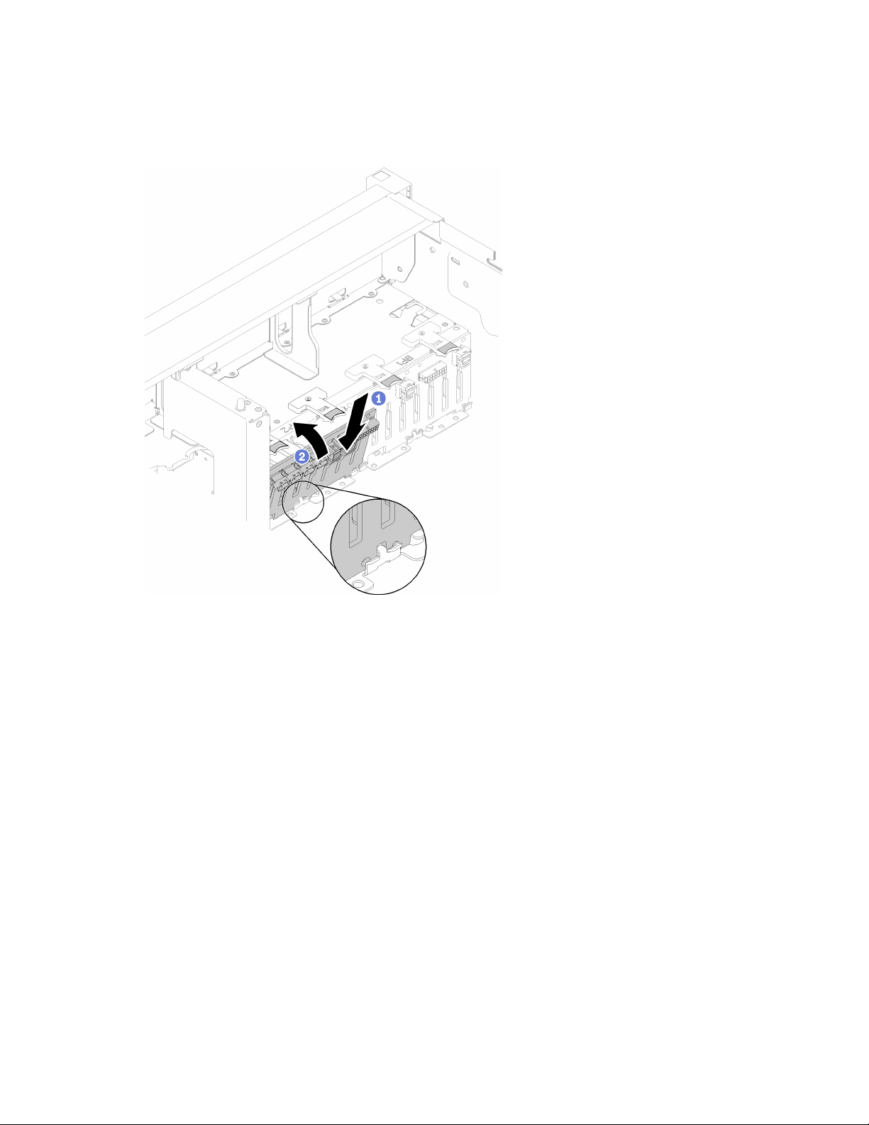
Step 2. Align the tabs on the bottom of the drive backplane with the slots on the system board, and insert
them into the slots.
Step 3. Push the top of the drive backplane toward the front of the server until it clicks in place.
Figure 59. Drive backplane installation
Step 4. Apply drive bay labels based on the type of backplane installed. Several drive bay labels come with
each type of the supported drive backplane:
• 8-bay backplane
– 12-15 (NVMe)
Apply this label to drive bay 12-15 if an AnyBay backplane is installed to drive bay 8-15.
– 12-15
Apply this label to drive bay 12-15 if an 8-bay backplane is installed to drive bay 8-15
– 4-7
Apply this label to drive bay 4-7 if an 8-bay backplane is installed to drive bay 0-7.
• AnyBay backplane
– 4-7 (NVMe)
Apply this label to drive bay 4-7 if an AnyBay backplane is installed to drive bay 0-7.
– 12-15 (NVMe)
Apply this label to drive bay 12-15 if an AnyBay backplane is installed to drive bay 8-15.
Note: Only drive bay 4-7 and 12-15 may support NVMe solid-state drives when the AnyBay
backplane is installed. Drive bay 0-3 and 8-11 always support SATA/SAS drives only.
76
ThinkSystem SR860 Setup Guide
Page 85
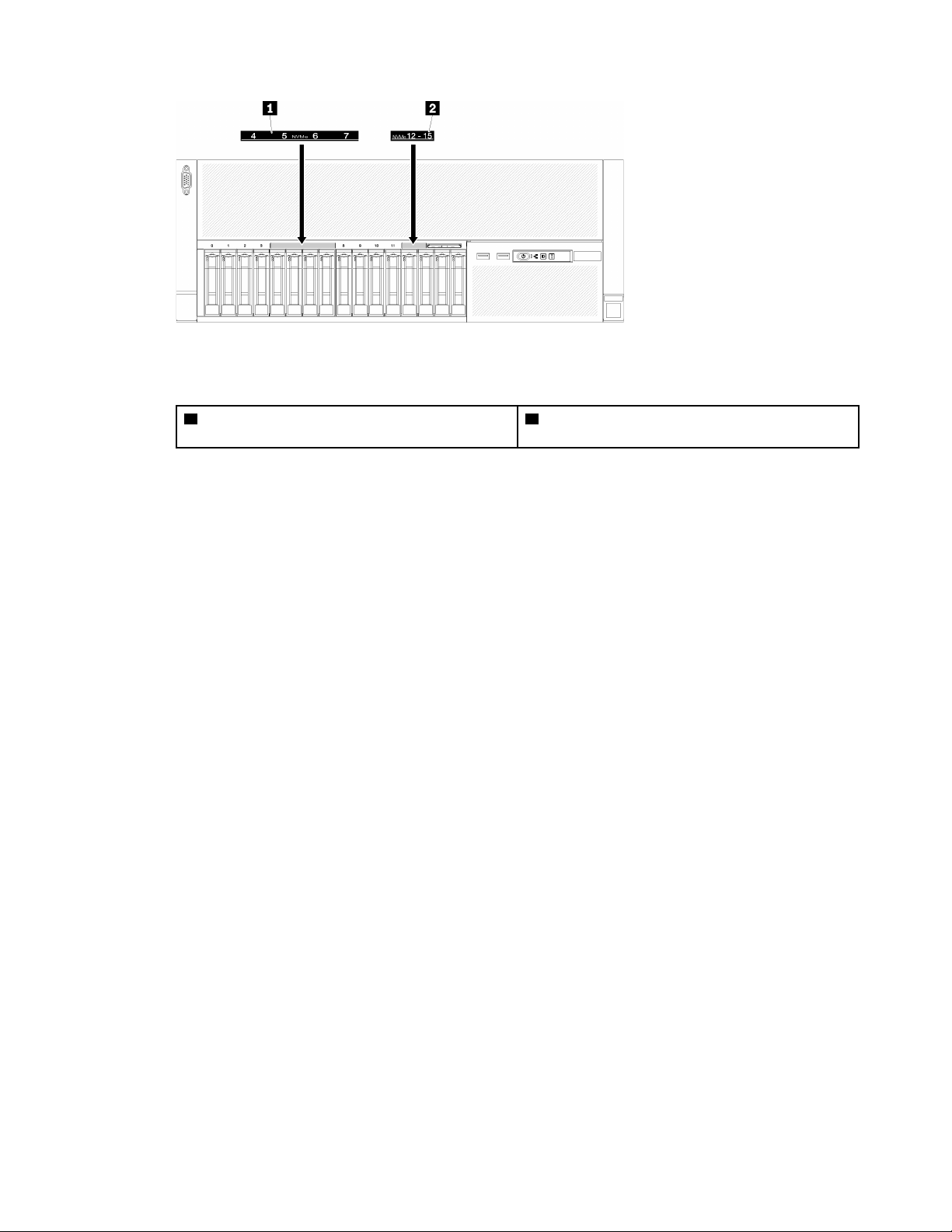
Figure 60. Drive bay labels of both NVMe and SATA/SAS drives
Table 40. Drive bay labels of both NVMe and SATA/SAS drives
1 Drive bay 4-7 label of both NVMe and SATA/SAS
drives
2 Drive bay 12-15 label of both NVMe and SATA/
SAS drives
After installing the drive backplane, complete the following steps:
1. Connect the cables to the drive backplane. If the type of drive backplane is changed, it is necessary to
reroute the signal cables (see “Internal cable routing” on page 33 for detailed instructions).
2. Install the drives (see “Install a 2.5-inch hot-swap drive” on page 77).
3. If the system board air baffle or the processor and memory expansion tray and processor and memory
expansion tray air baffle have been removed, install them (see “Install the system board air baffle and the
power interposer” on page 80 or “Install the processor and memory expansion tray ” on page 81).
4. Install the chassis air baffle (see “Install the chassis air baffle” on page 93).
5. Install the top cover (see “Install the top cover” on page 97).
6. Reconnect the power cords and any cables that you removed.
7. If the server is installed in a rack, reinstall the server into the rack.
8. Power on the server and any peripheral devices.
Install a 2.5-inch hot-swap drive
Use this procedure to install a 2.5-inch drive.
Following are the types of drives supported by this server:
• NVMe solid-state drive
• SATA/SAS solid-state drive
• SATA/SAS hard-disk drive
For a complete list of supported optional device for this server, see http://www.lenovo.com/serverproven/.
Before installing a 2.5-inch hot-swap drive:
1. Read the safety information and installation guidelines (see “Safety” on page iii and “Installation
Guidelines” on page 58).
2. Touch the static-protective package that contains the component to any unpainted metal surface on the
server; then, remove it from the package and place it on a static-protective surface.
Chapter 3. Server hardware setup 77
Page 86
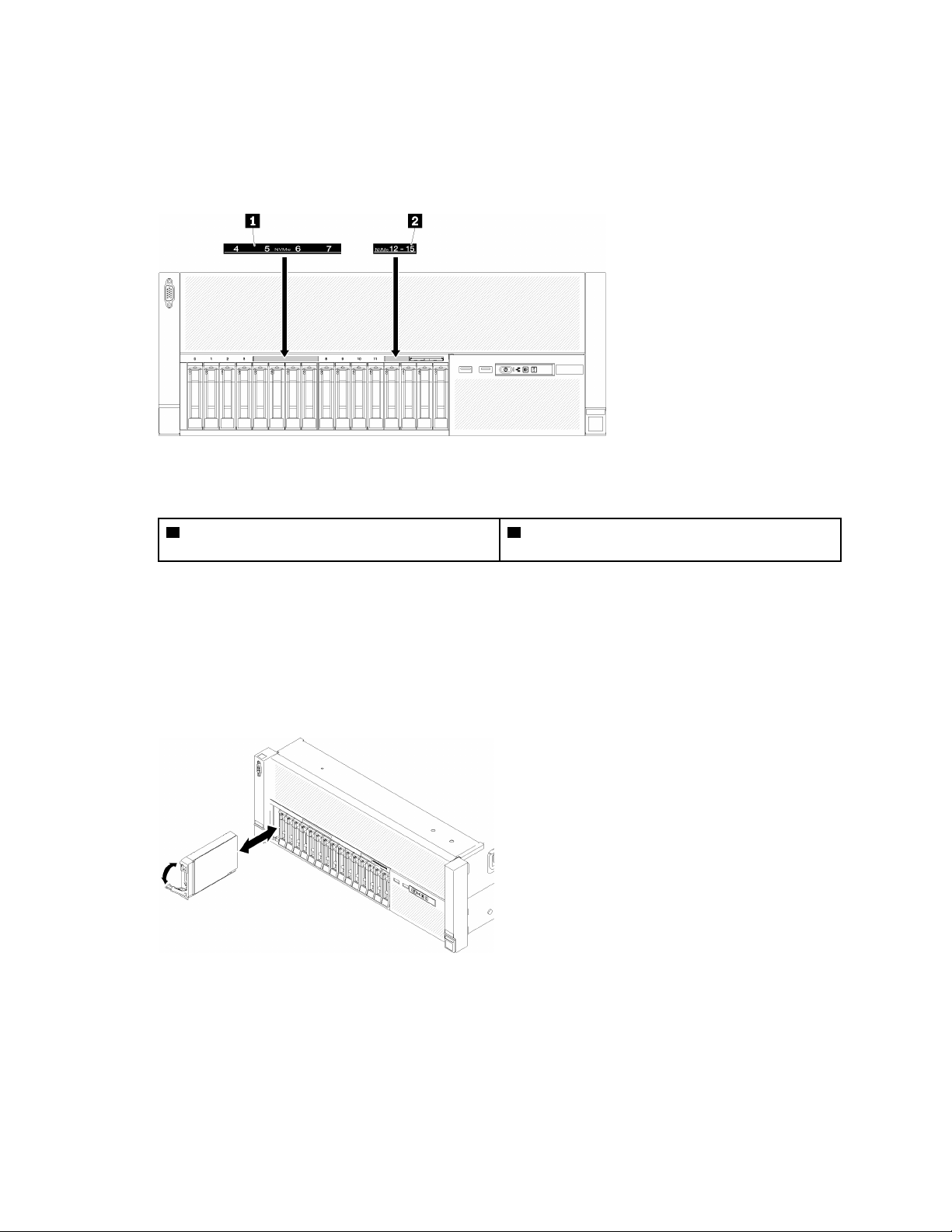
To install a 2.5-inch drive, complete the following steps:
Step 1. Determine the available drive bays based on the drive bay labels applied. The following labels
indicate that the drive bays support both NVMe and SATA/SAS drives. Otherwise, only SATA/SAS
drives are supported.
Figure 61. Drive bay labels of both NVMe and SATA/SAS drives
Table 41. Drive bay labels of both NVMe and SATA/SAS drives
1 Drive bay 4-7 label of both NVMe and SATA/SAS
drives
2 Drive bay 12-15 label of both NVMe and SATA/
SAS drives
Notes:
1. Make sure to install the correct type of drives into supported by corresponding drive bays.
Drive type information is available on the drive.
Step 2. Remove the drive bay filler if it has been installed in the drive bay.
Step 3. Gently rotate the release latch away to unlock the drive handle.
Step 4. Slide the drive into the drive bay, and push it until it stops.
Figure 62. Drive installation
Step 5. Rotate the drive-tray handle back to the locked position.
After installing the 2.5-inch hot-swap drive, check the drive status LED to verify if the drive is operating
correctly:
• If the yellow LED is lit continuously, it is malfunctioning and must be replaced.
78
ThinkSystem SR860 Setup Guide
Page 87
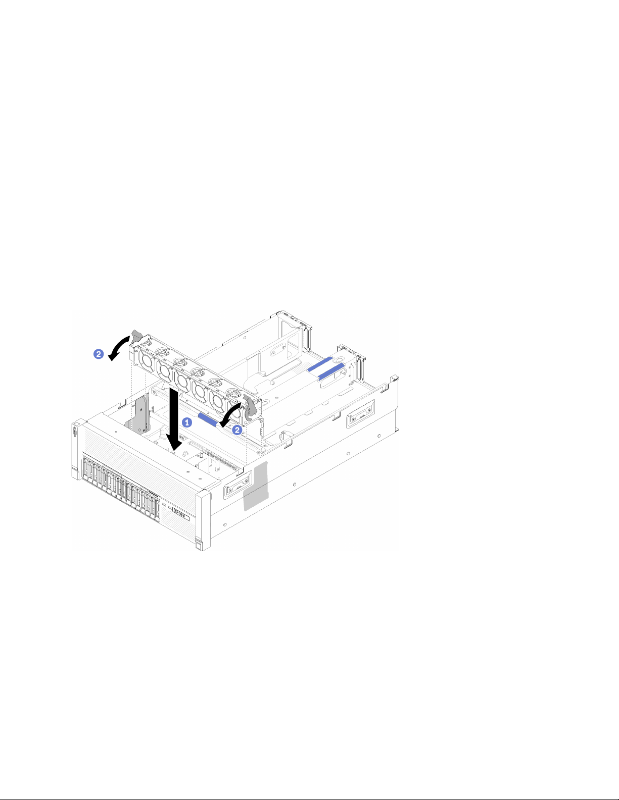
• If the green LED is flashing, the drive is functioning.
Note: If the server is configured for RAID operation through a ThinkSystem RAID adapter, you might have to
reconfigure your disk arrays after you install drives. See the ThinkSystem RAID adapter documentation for
additional information about RAID operation and complete instructions for using ThinkSystem RAID
adapters.
Install the fan cage assembly
Use this procedure to install the fan cage assembly.
Before installing the fan cage assembly:
1. Read the safety information and installation guidelines (see “Safety” on page iii and “Installation
Guidelines” on page 58).
2. Touch the static-protective package that contains the component to any unpainted metal surface on the
server; then, remove it from the package and place it on a static-protective surface.
To install the fan cage assembly, complete the following steps:
Figure 63. Fan cage assembly installation
Step 1. Align the fan cage assembly to the slots on both sides of the server, and lower it into the server.
Step 2. Rotate the fan cage release latches down until they click.
After installing the fan cage assembly, complete the following steps:
1. Install the chassis air baffle (see “Install the chassis air baffle” on page 93).
2. Install the top cover (see “Install the top cover” on page 97).
3. Reconnect the power cords and any cables that you removed.
4. If the server is installed in a rack, reinstall the server into the rack.
5. Power on the server and any peripheral devices.
Chapter 3. Server hardware setup 79
Page 88
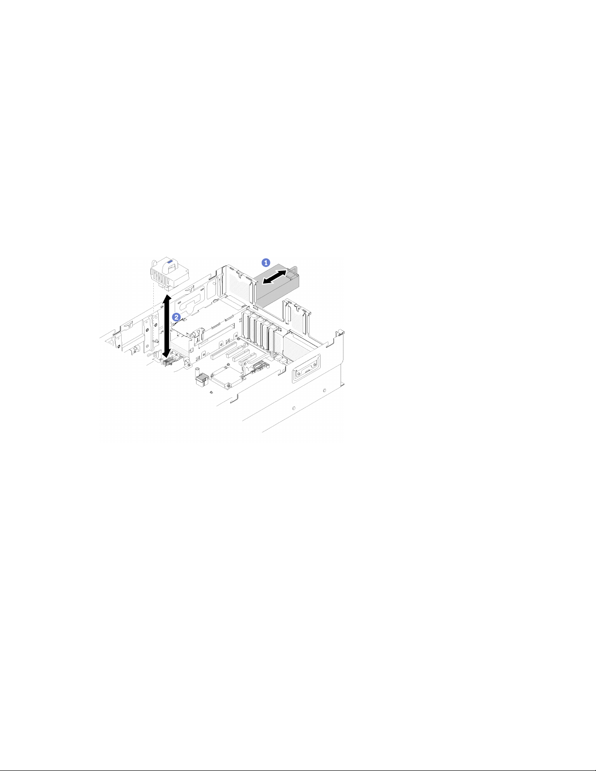
Install the system board air baffle and the power interposer
Use this procedure to install the system board air baffle and the power interposer.
Before installing the system board air baffle:
1. Read the safety information and installation guidelines (see “Safety” on page iii and “Installation
Guidelines” on page 58).
2. Touch the static-protective package that contains the component to any unpainted metal surface on the
server; then, remove it from the package and place it on a static-protective surface.
To install the system board air baffle, complete the following steps:
Step 1. Slightly slide power supply 2 out from the power supply bay (see “Remove a hot-swap power
supply unit” in ThinkSystem SR860 Maintenance Manual).
Step 2. Align the power interposer to the server, and lower it until it sits firmly in place.
Figure 64. Power interposer installation
Step 3. Align the two pairs of nailheads of the system board air baffle to slots, and lower it into the server.
Attention: Air baffle is required for airflow that creates proper cooling. Make sure proper air baffle
(s) for system configuration is installed before the power is turned on.
80
ThinkSystem SR860 Setup Guide
Page 89
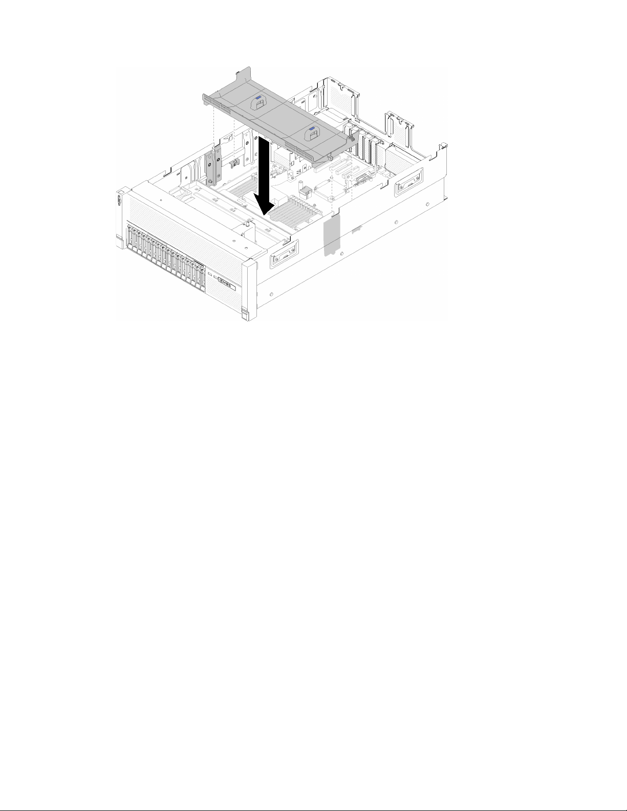
Figure 65. System board air baffle installation
After installing the system board air baffle, complete the following steps:
1. Install the PCIe expansion tray (see “Install the PCIe expansion tray” on page 93).
2. Install the top cover (see “Install the top cover” on page 97).
3. Reconnect the power cords and any cables that you removed.
4. If the server is installed in a rack, reinstall the server into the rack.
5. Power on the server and any peripheral devices.
Install the processor and memory expansion tray
Use this procedure to install the processor and memory expansion tray.
Before installing the processor and memory expansion tray:
1. Read the safety information and installation guidelines (see “Safety” on page iii and “Installation
Guidelines” on page 58).
2. Touch the static-protective package that contains the component to any unpainted metal surface on the
server; then, remove it from the package and place it on a static-protective surface.
To install processor and memory expansion tray, complete the following steps:
Step 1. If a power interposer and a system board air baffle are installed, remove them (see “Remove the
system board air baffle and the power interposer” on page 66).
Step 2. Install an processor and memory expansion tray air baffle on the system board. Make sure it is
properly installed before installing the processor and memory expansion tray.
Chapter 3. Server hardware setup 81
Page 90
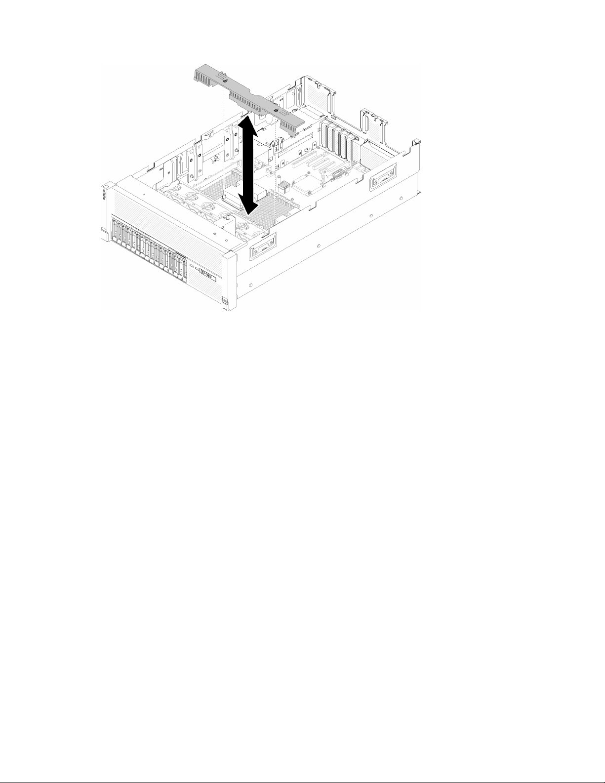
Figure 66. Processor and memory expansion tray air baffle installation
Attention: Air baffle is required for airflow that creates proper cooling. Make sure proper air baffle
(s) for system configuration is installed before the power is turned on.
Step 3. Slightly slide power supply 2 out from the power supply bay (see “Remove a hot-swap power
supply unit” in ThinkSystem SR860 Maintenance Manual).
Step 4. Grip on the blue touch point on the handle of the expansion tray, and lift it up; then, lower the tray
vertically into the server with nailheads aligned to the slots on both sides.
Step 5. Rotate the handle down to make sure the expansion tray is fully seated into the system board.
82
ThinkSystem SR860 Setup Guide
Page 91
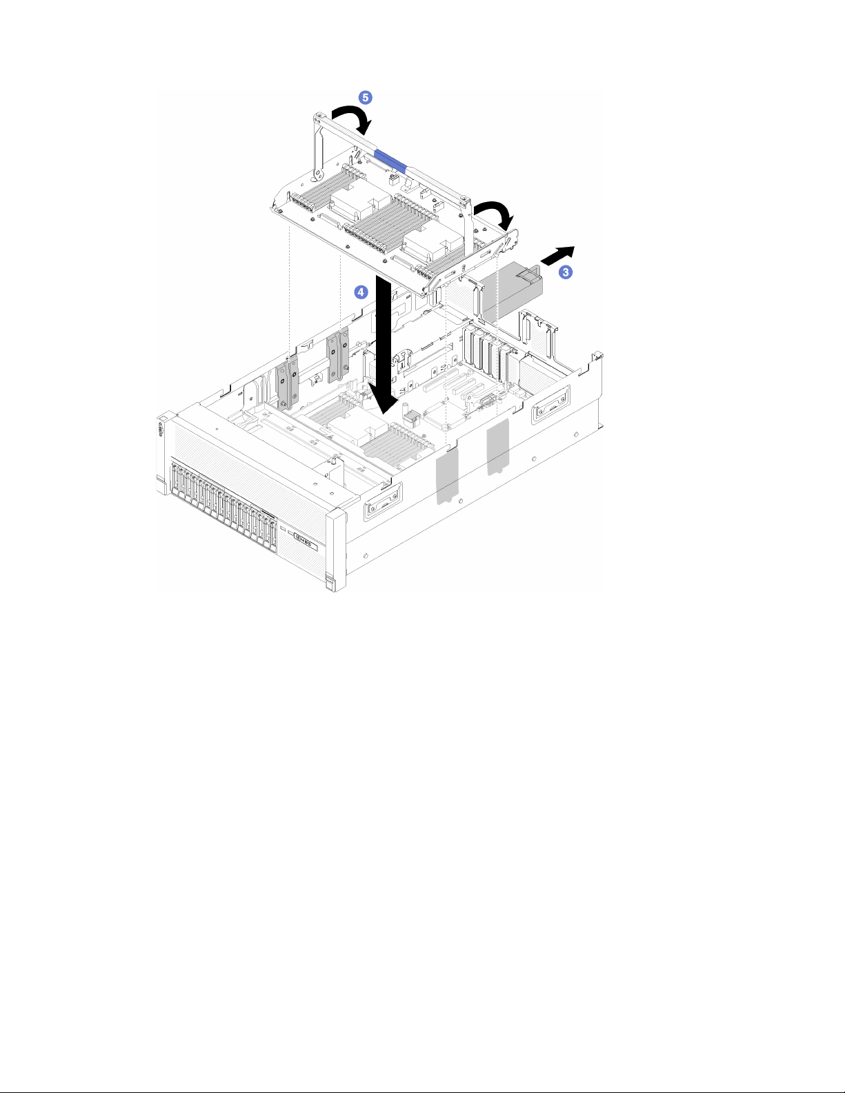
Figure 67. Processor and memory expansion tray installation
Step 6. Install DIMMs (see “Install a memory module” on page 74), PHMs (see “Install a processor-heat-
sink module” on page 71), and another processor and memory expansion tray air baffle on the
expansion tray.
Chapter 3. Server hardware setup 83
Page 92
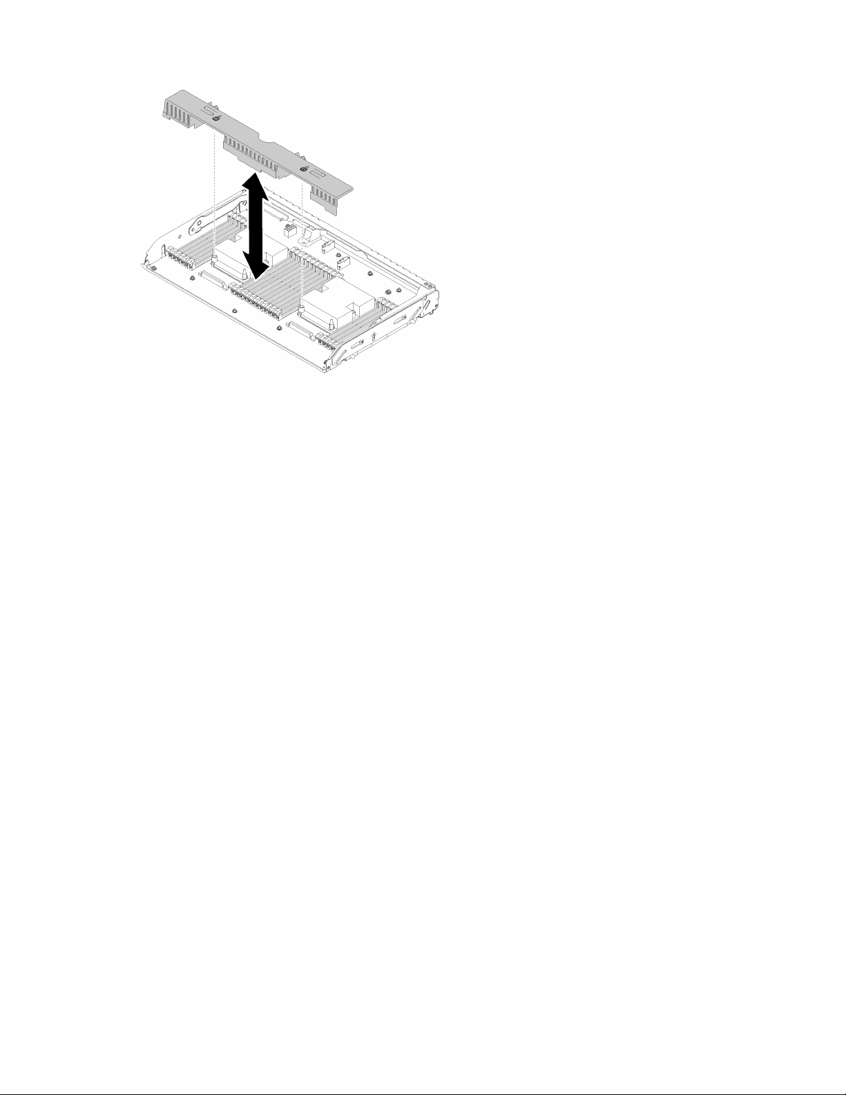
Figure 68. Processor and memory expansion tray air baffle installation
Attention:
1. For the optimal performance, make sure both PHMs and corresponding DIMMs are installed to
the processor and memory expansion tray.
2. Air baffle is required for airflow that creates proper cooling. Make sure proper air baffle(s) for
system configuration is installed before the power is turned on.
After installing the processor and memory expansion tray, complete the following steps:
1. Reinstall power supply 2 (see “Install hot-swap power supply” in ThinkSystem SR860 Maintenance
Manual).
2. Install the PCIe expansion tray (see “Install the PCIe expansion tray” on page 93).
3. Install the top cover (see “Install the top cover” on page 97).
4. Reconnect the power cords and any cables that you removed.
5. Power on the server and any peripheral devices.
Install the PCIe riser card assembly
Use this procedure to install the PCIe riser card assembly.
Before installing the PCIe riser card assembly:
1. Read the safety information and installation guidelines (see “Safety” on page iii and “Installation
Guidelines” on page 58).
2. Touch the static-protective package that contains the component to any unpainted metal surface on the
server; then, remove it from the package and place it on a static-protective surface.
3. Disconnect the USB 3.0 cable of operator panel tray assembly, and remove it vertically from the system
board.
84
ThinkSystem SR860 Setup Guide
Page 93
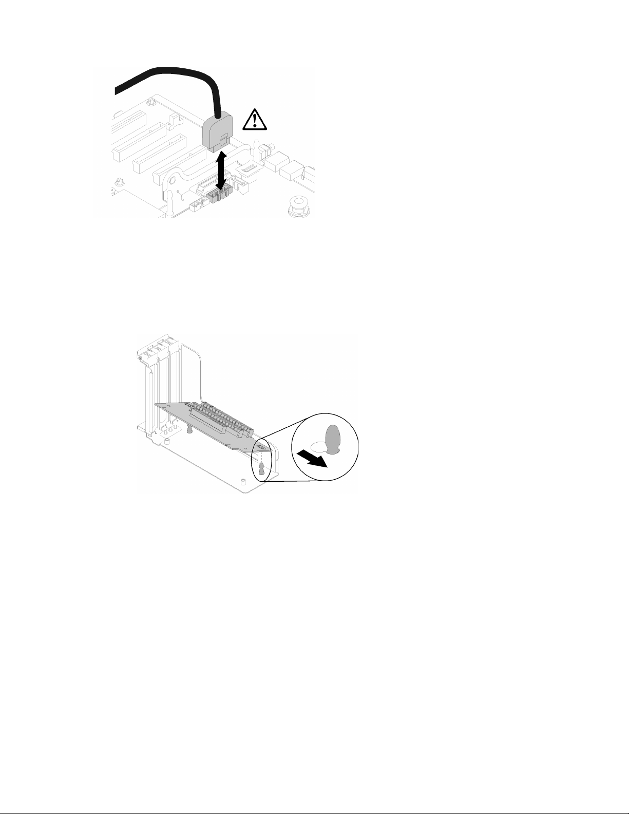
Figure 69. Removing USB 3.0 connector vertically
To install the PCIe riser card assembly, complete the following steps:
Step 1. Assemble the PCIe riser card assembly:
a. Align the bottom of the PCIe riser card to the slot, and rotate the top to fit it into the slot on the
riser-cage; then, move the PCIe riser card slightly to fit the holes into the pins.
Figure 70. PCIe riser card assembly
b. Install the PCIe riser card to the riser cage with screws.
Chapter 3. Server hardware setup 85
Page 94
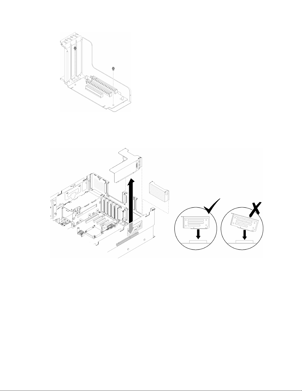
Figure 71. PCIe riser card assembly
Step 2. Align the PCIe riser card assembly with the connector on the system board; then, push it in until it
clicks in place.
Figure 72. PCIe riser card assembly installation
Step 3. Reconnect all the cables disconnected previously.
After installing the PCIe riser card assembly, complete the following steps:
1. Reconnect the USB 3.0 cable of operator panel tray assembly vertically to the system board.
86
ThinkSystem SR860 Setup Guide
Page 95
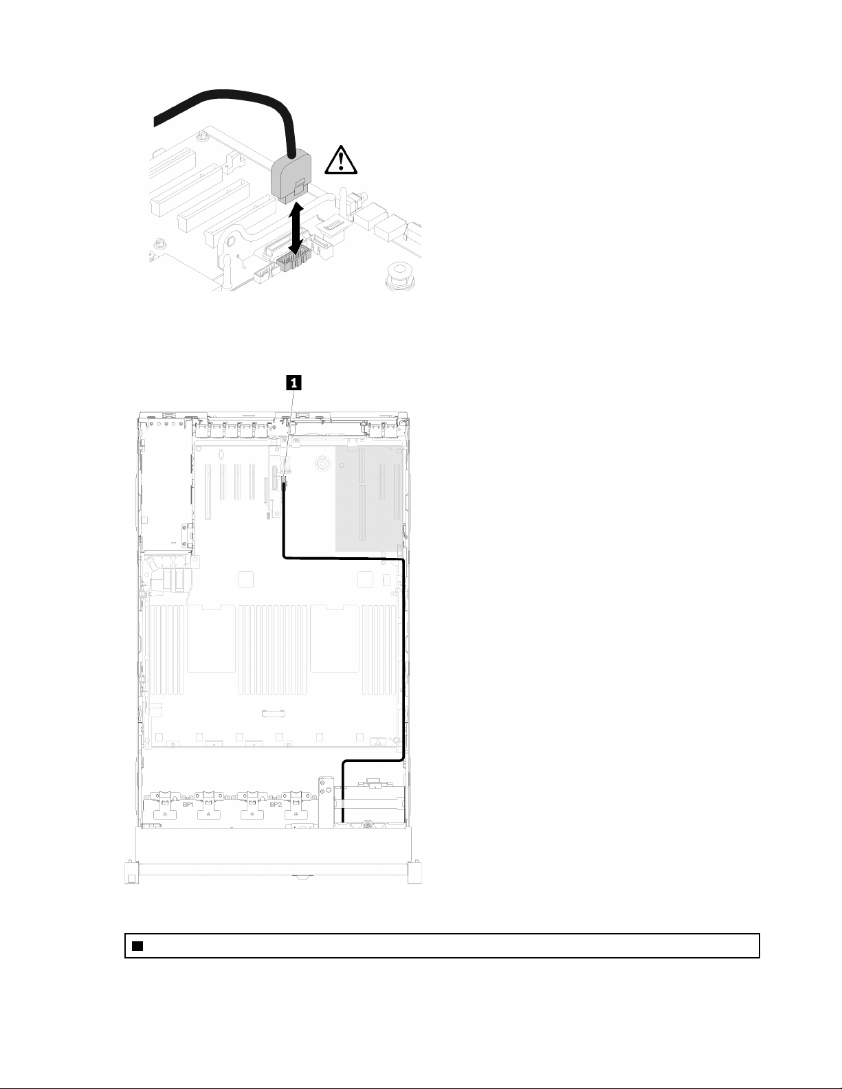
Figure 73. Installing USB 3.0 connector vertically
Route the USB 3.0 cable in the cable guide and away from the PCIe slots area (marked in gray).
Figure 74. Routing USB 3.0 cable
1 USB 3.0 connector
2. Install the PCIe expansion tray (see “Install the PCIe expansion tray” on page 93).
Chapter 3. Server hardware setup 87
Page 96
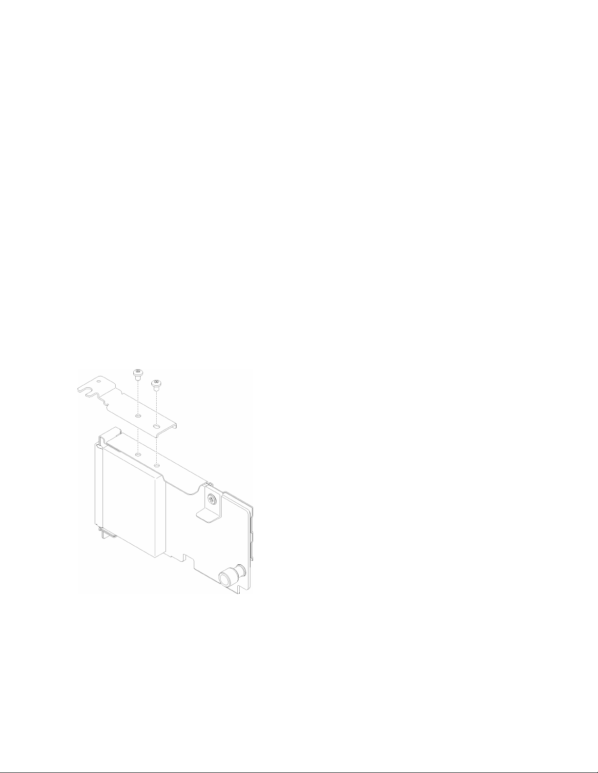
3. Install the top cover (see “Install the top cover” on page 97).
4. Reconnect the power cords and any cables that you removed.
5. If the server is installed in a rack, reinstall the server into the rack.
6. Power on the server and any peripheral devices.
Install the LOM adapter
Use this procedure to install the LOM adapter.
Note: When both LOM adapter and ML2 adapter are installed to the server, the system can support up to
two additional network adapters.
Before installing the LOM adapter:
1. Read the safety information and installation guidelines (see “Safety” on page iii and “Installation
Guidelines” on page 58).
2. Touch the static-protective package that contains the component to any unpainted metal surface on the
server; then, remove it from the package and place it on a static-protective surface.
3. Make sure the LOM adapter to be installed supports the bandwidth of the network environment.
Following are the requirements:
• 1GbE LOM adapter: maximal bandwidth of network environment is 1GB.
• 10GbE LOM adapter: minimal bandwidth of network environment is 1GB.
4. Attach the mounting bracket with the two screws as illustrated.
Figure 75. LOM adapter assembly
To install the LOM adapter, complete the following steps:
Step 1. Open the retention latch.
Step 2. Align the LOM adapter to the connector, and push it in.
Step 3. Tighten the captive thumbscrew to lock it to the connector.
88
ThinkSystem SR860 Setup Guide
Page 97
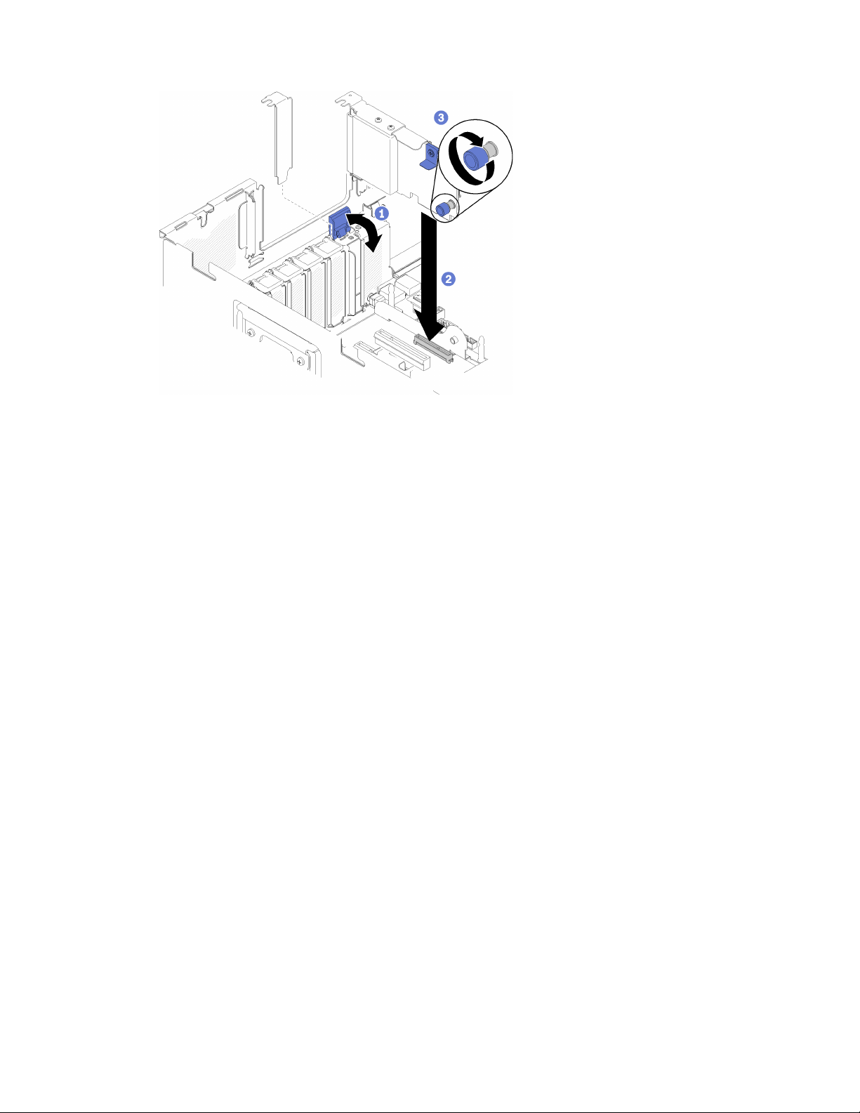
Figure 76. LOM adapter installation
Step 4. Close the retention latch.
After installing the LOM adapter, complete the following steps:
1. Install the PCIe expansion tray (see “Install the PCIe expansion tray” on page 93).
2. Install the top cover (see “Install the top cover” on page 97).
3. Reconnect the power cords and any cables that you removed.
4. Power on the server and any peripheral devices.
How to adjust the position of the retainer on the M.2 backplane
Use this information to adjust the position of the retainer on the M.2 backplane.
Before you adjust the position of the retainer on the M.2 backplane, complete the following steps:
1. Read the safety information and installation guidelines (see “Safety” on page iii and “Installation
Guidelines” on page 58).
2. Touch the static-protective package that contains the component to any unpainted metal surface on the
server; then, remove it from the package and place it on a static-protective surface.
To adjust the position of the retainer on the M.2 backplane, complete the following steps:
Step 1. Locate the correct keyhole that the retainer should be installed into to accommodate the particular
size of the M.2 drive you wish to install.
Step 2. Press both sides of the retainer and move it forward until it is in the large opening of the keyhole;
then, remove it from the backplane.
Step 3. Insert the retainer into the correct keyhole and slide it backwards until the nubs are in the holes.
Chapter 3. Server hardware setup 89
Page 98
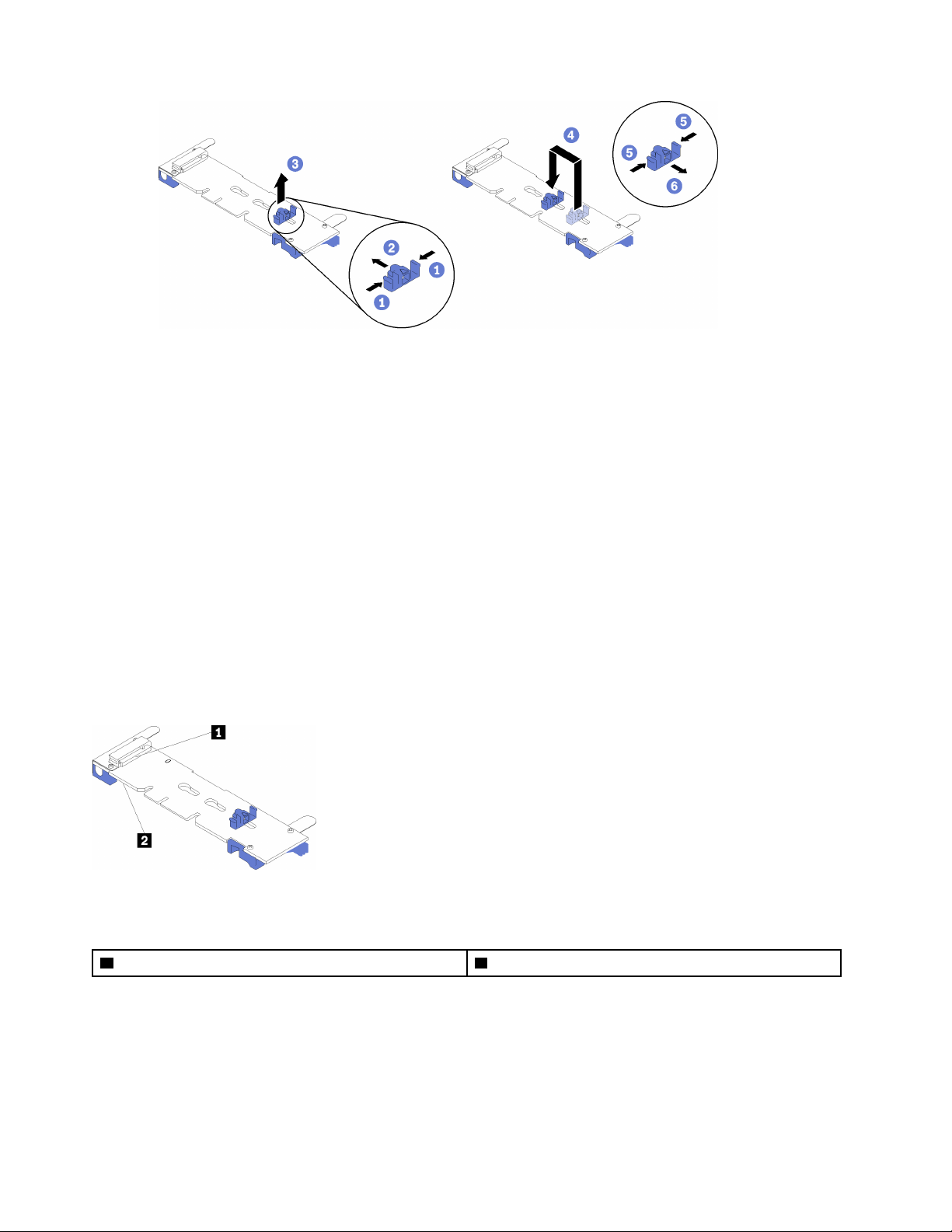
Figure 77. M.2 retainer adjustment
Install an M.2 drive in the M.2 backplane
Use this procedure to install an an M.2 drive in the M.2 backplane.
Before installing an M.2 drive in the M.2 backplane:
1. Read the safety information and installation guidelines (see “Safety” on page iii and “Installation
Guidelines” on page 58).
2. Touch the static-protective package that contains the component to any unpainted metal surface on the
server; then, remove it from the package and place it on a static-protective surface.
To install an M.2 drive in the M.2 backplane, complete the following steps:
Notes:
• Some M.2 backplanes support two identical M.2 drives. When two drives are installed, align and support
both drives when sliding the retainer forward to secure the drives.
• Install the M.2 drive in slot 0 first.
Figure 78. M.2 drive slot
Table 42. M.2 drive slot
1 Slot 0 2 Slot 1
Step 1. Locate the connector on each side of the M.2 backplane.
Step 2. Insert the M.2 drive at an angle (approximately 30 degrees) into the connector and rotate it until the
notch catches on the lip of the retainer; then, slide the retainer forward (toward the connector) to
secure the M.2 drive in the M.2 backplane.
90
ThinkSystem SR860 Setup Guide
Page 99
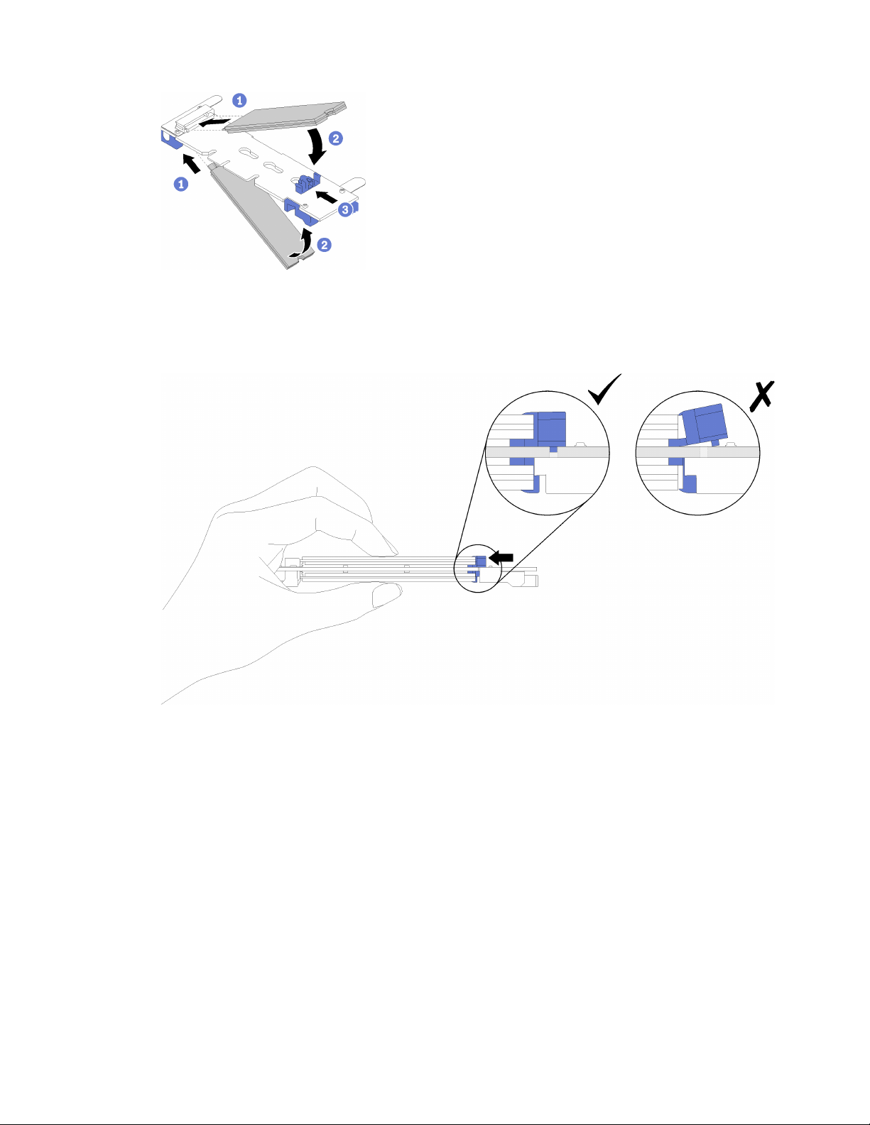
Figure 79. M.2 drive installation
Attention: When sliding the retainer forward, make sure the two nubs on the retainer enter the
small holes on the M.2 backplane. Once they enter the holes, you will hear a soft “click” sound.
Figure 80. M.2 drive installation with the retainers in place
After installing an M.2 drive in the M.2 backplane, see “Install the M.2 backplane” on page 91 to complete
installation.
Install the M.2 backplane
Use this procedure to install the M.2 backplane.
Before installing the M.2 backplane:
1. Read the safety information and installation guidelines (see “Safety” on page iii and “Installation
Guidelines” on page 58).
2. Install an M.2 drive to every available connector on the M.2 backplane (see “Install an M.2 drive in the
M.2 backplane” on page 90).
3. Touch the static-protective package that contains the component to any unpainted metal surface on the
server; then, remove it from the package and place it on a static-protective surface.
Chapter 3. Server hardware setup 91
Page 100
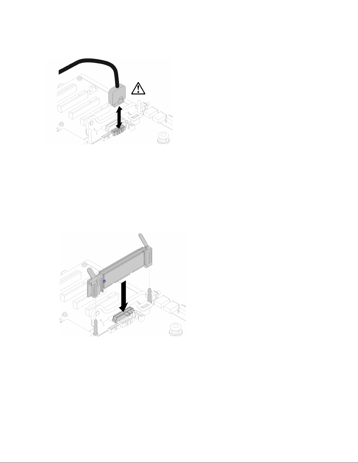
4. Disconnect the USB 3.0 cable of operator panel tray assembly, and remove it vertically from the system
board.
Figure 81. Removing USB 3.0 connector vertically
To install the M.2 backplane, complete the following steps:
Note: Before installing the M.2 backplane, make sure an M.2 drive is installed to every available connector
on the M.2 backplane.
Step 1. Align the openings located at the bottom of the blue plastic supports at each end of the M.2
backplane with the guide pin on the system board and T-head pins on the hard drive cage; then,
insert the backplane in the system board connector. Press down on the M.2 backplane to fully seat
it.
Figure 82. M.2 backplane installation
After installing the M.2 backplane, complete the following steps:
1. Reinstall the PCIe riser card if necessary (see “Install the PCIe riser card assembly” on page 84).
2. Reinstall the LOM adapter if necessary (see “Install the LOM adapter” on page 88).
3. Install the PCIe expansion tray (see “Install the PCIe expansion tray” on page 93).
4. Install the top cover (see “Install the top cover” on page 97).
5. Reconnect the power cords and any cables that you removed.
92
ThinkSystem SR860 Setup Guide
 Loading...