


ThinkSystem SR250
Maintenance Manual
Machine Types: 7Y51, 7Y52, 7Y72 and 7Y73

Note
Before using this information and the product it supports, be sure to read and understand the safety
information and the safety instructions, which are available at:
http://thinksystem.lenovofiles.com/help/topic/safety_documentation/pdf_files.html
In addition, be sure that you are familiar with the terms and conditions of the Lenovo warranty for your server,
which can be found at:
http://datacentersupport.lenovo.com/warrantylookup
First Edition (November 2018)
© Copyright Lenovo 2018.
LIMITED AND RESTRICTED RIGHTS NOTICE: If data or software is delivered pursuant to a General Services
Administration (GSA) contract, use, reproduction, or disclosure is subject to restrictions set forth in Contract No. GS-35F-
05925.

Contents
Safety . . . . . . . . . . . . . . . . . . iii
Safety inspection checklist . . . . . . . . . . . iv
Chapter 1. Introduction . . . . . . . . . 1
Specifications . . . . . . . . . . . . . . . . 1
Firmware updates . . . . . . . . . . . . . . . 5
Configuring the LAN over USB interface
manually. . . . . . . . . . . . . . . . . 8
Installing the LAN over USB Windows device
driver . . . . . . . . . . . . . . . . . . 9
Tech Tips . . . . . . . . . . . . . . . . . . 9
Security advisories . . . . . . . . . . . . . 10
Power on the server . . . . . . . . . . . . . 10
Power off the server . . . . . . . . . . . . . 10
Chapter 2. Server components . . . . 11
Front view . . . . . . . . . . . . . . . . . 12
Front operator panel . . . . . . . . . . . 14
Rear view . . . . . . . . . . . . . . . . . 15
System-board switches, jumpers, and buttons. . . 16
System-board LEDs . . . . . . . . . . . 16
System-board connectors . . . . . . . . . 17
System-board jumpers and buttons . . . . . 19
RAID adapters and the NVMe switch card . . . . 20
Backplates and backplanes . . . . . . . . . . 21
PCIe riser assembly . . . . . . . . . . . . . 23
Internal cable routing. . . . . . . . . . . . . 24
Front VGA cable. . . . . . . . . . . . . 24
Fan cable . . . . . . . . . . . . . . . 26
Power supply . . . . . . . . . . . . . . 27
Flash power module . . . . . . . . . . . 29
3.5-inch simple-swap drive model . . . . . . 30
Four 3.5-inch hot-swap drive model . . . . . 32
Eight 2.5-inch hot-swap drive model . . . . . 34
Ten 2.5-inch hot-swap drive model . . . . . 36
Parts list. . . . . . . . . . . . . . . . . . 38
Power cords . . . . . . . . . . . . . . 45
Chapter 3. Hardware replacement
procedures . . . . . . . . . . . . . . . 47
Installation Guidelines . . . . . . . . . . . . 47
System reliability guidelines . . . . . . . . 48
Working inside the server with the power on . . 49
Handling static-sensitive devices . . . . . . 49
Adapter replacement. . . . . . . . . . . . . 49
Remove an adapter . . . . . . . . . . . 49
Install an adapter . . . . . . . . . . . . 50
Air baffle replacement . . . . . . . . . . . . 51
Remove the air baffle . . . . . . . . . . . 51
Install the air baffle . . . . . . . . . . . . 52
Backplane replacement. . . . . . . . . . . . 53
Remove the hot-swap drive backplane . . . . 53
Install the hot-swap drive backplane . . . . . 54
Backplate replacement . . . . . . . . . . . . 56
Remove the backplate . . . . . . . . . . 56
Install the backplate . . . . . . . . . . . 57
CMOS battery replacement . . . . . . . . . . 58
Remove the CMOS battery . . . . . . . . 58
Install the CMOS battery (CR2032) . . . . . 59
DIMM replacement . . . . . . . . . . . . . 61
Remove a DIMM. . . . . . . . . . . . . 61
Install a DIMM . . . . . . . . . . . . . 63
Drive replacement . . . . . . . . . . . . . . 65
Remove a simple-swap drive. . . . . . . . 65
Install a simple-swap drive. . . . . . . . . 66
Remove a hot-swap drive . . . . . . . . . 66
Install a hot-swap drive . . . . . . . . . . 67
Fan replacement . . . . . . . . . . . . . . 68
Remove a fan . . . . . . . . . . . . . . 68
Install a fan. . . . . . . . . . . . . . . 70
Flash power module replacement . . . . . . . . 72
Remove the flash power module . . . . . . 72
Install the flash power module . . . . . . . 74
Front operator panel replacement. . . . . . . . 75
Remove the front operator panel (2.5-inch
HDD model) . . . . . . . . . . . . . . 75
Install the front operator panel (2.5-inch HDD
model) . . . . . . . . . . . . . . . . 77
Remove the front operator panel (3.5-inch
HDD model) . . . . . . . . . . . . . . 79
Install the front operator panel (3.5-inch HDD
model) . . . . . . . . . . . . . . . . 81
Heat sink replacement . . . . . . . . . . . . 83
Remove the heat sink. . . . . . . . . . . 83
Install the heat sink. . . . . . . . . . . . 85
M.2 drive replacement . . . . . . . . . . . . 86
Remove the M.2 drive . . . . . . . . . . 86
Install the M.2 drive . . . . . . . . . . . 88
PCIe riser assembly replacement . . . . . . . . 90
Remove the PCIe riser assembly . . . . . . 90
Install the PCIe riser assembly . . . . . . . 91
Power supply unit replacement. . . . . . . . . 93
Remove the fixed power supply unit . . . . . 93
Install the fixed power supply unit . . . . . . 95
© Copyright Lenovo 2018 i

Remove a hot-swap power supply unit . . . . 97
Install a hot-swap power supply unit . . . . . 99
Power interface board replacement . . . . . . . 101
Remove the power interface board . . . . . 101
Install the power interface board . . . . . . 104
Processor replacement . . . . . . . . . . . . 107
Remove the processor . . . . . . . . . . 107
Install the processor . . . . . . . . . . . 108
Rack latches replacement. . . . . . . . . . . 110
Remove the rack latches . . . . . . . . . 110
Install the rack latches . . . . . . . . . . 112
RAID adapter replacement . . . . . . . . . . 114
Remove the RAID adapter . . . . . . . . . 114
Install the RAID adapter . . . . . . . . . . 115
Security bezel replacement . . . . . . . . . . 117
Remove the security bezel . . . . . . . . . 117
Install the security bezel . . . . . . . . . . 118
System board replacement . . . . . . . . . . 119
Remove the system board . . . . . . . . . 119
Install the system board . . . . . . . . . . 121
Update the Universal Unique Identifier
(UUID). . . . . . . . . . . . . . . . . 124
Update the DMI/SMBIOS data . . . . . . . 125
Enable TPM . . . . . . . . . . . . . . 127
Enable UEFI Secure Boot . . . . . . . . . 131
Top cover replacement . . . . . . . . . . . . 131
Remove the top cover . . . . . . . . . . 132
Install the top cover . . . . . . . . . . . 133
TPM card (for China only) replacement. . . . . . 134
Remove the TPM card (for China only) . . . . 134
Install the TPM card (for China only) . . . . . 135
VGA cable replacement. . . . . . . . . . . . 136
Remove the VGA cable (2.5-inch HDD
model) . . . . . . . . . . . . . . . . 136
Install the VGA cable (2.5-inch HDD
model) . . . . . . . . . . . . . . . . 137
Remove the VGA cable (3.5-inch HDD
model) . . . . . . . . . . . . . . . . 138
Install the VGA cable (3.5-inch HDD
model) . . . . . . . . . . . . . . . . 140
Complete the parts replacement . . . . . . . . 142
Chapter 4. Problem
determination . . . . . . . . . . . . . 143
Event logs . . . . . . . . . . . . . . . . . 143
The front operator panel and error LEDs . . . . . 145
Power supply LEDs . . . . . . . . . . . 146
System-board LEDs . . . . . . . . . . . 147
General problem determination procedures . . . . 148
Resolving suspected power problems . . . . 148
Resolving suspected Ethernet controller
problems . . . . . . . . . . . . . . . 149
Troubleshooting by symptom . . . . . . . . . 149
Power on and power off problems. . . . . . 150
Memory problems . . . . . . . . . . . . 151
Hard disk drive problems . . . . . . . . . 152
Monitor and video problems . . . . . . . . 154
Keyboard, mouse, or USB-device
problems . . . . . . . . . . . . . . . 155
Optional-device problems . . . . . . . . . 156
Serial-device problems . . . . . . . . . . 158
Intermittent problems. . . . . . . . . . . 158
Power problems. . . . . . . . . . . . . 159
Network problems . . . . . . . . . . . . 159
Observable problems. . . . . . . . . . . 160
Software problems. . . . . . . . . . . . 162
Appendix A. Getting help and
technical assistance . . . . . . . . . . 165
Before you call . . . . . . . . . . . . . . . 165
Collecting service data . . . . . . . . . . . . 166
Contacting Support . . . . . . . . . . . . . 167
Appendix B. Notices. . . . . . . . . . 169
Trademarks . . . . . . . . . . . . . . . . 170
Important notes. . . . . . . . . . . . . . . 170
Particulate contamination . . . . . . . . . . . 170
Telecommunication regulatory statement. . . . . 171
Electronic emission notices . . . . . . . . . . 171
Taiwan BSMI RoHS declaration. . . . . . . 172
Taiwan import and export contact information . . . 172
Index . . . . . . . . . . . . . . . . . . 173
ii ThinkSystem SR250 Maintenance Manual
Safety
Before installing this product, read the Safety Information.
Antes de instalar este produto, leia as Informações de Segurança.
在安装本产品之前,请仔细阅读 Safety Information (安全信息)。
Læs sikkerhedsforskrifterne, før du installerer dette produkt.
Lees voordat u dit product installeert eerst de veiligheidsvoorschriften.
Ennen kuin asennat tämän tuotteen, lue turvaohjeet kohdasta Safety Information.
Avant d'installer ce produit, lisez les consignes de sécurité.
Vor der Installation dieses Produkts die Sicherheitshinweise lesen.
Prima di installare questo prodotto, leggere le Informazioni sulla Sicurezza.
Les sikkerhetsinformasjonen (Safety Information) før du installerer dette produktet.
Antes de instalar este produto, leia as Informações sobre Segurança.
© Copyright Lenovo 2018 iii
Antes de instalar este producto, lea la información de seguridad.
Läs säkerhetsinformationen innan du installerar den här produkten.
Safety inspection checklist
Use the information in this section to identify potentially unsafe conditions with your server. As each machine
was designed and built, required safety items were installed to protect users and service technicians from
injury.
Important: Electrical grounding of the server is required for operator safety and correct system function.
Proper grounding of the electrical outlet can be verified by a certified electrician.
S041
CAUTION:
• This equipment must be installed or serviced by trained personnel, as defined by IEC 60950-1 and
IEC 62368-1, the Standard for Safety of audio/video, information and communication technology
equipment.
• Access to the equipment is by the use of a tool, lock and key, or other means of security, and is
controlled by the authority responsible for the location.
Make sure all power cords are disconnected from the system when reading the following step in
this manual: Turn off the server. Disconnect the power cords and all external cables.
Use the following checklist to verify that there are no potentially unsafe conditions:
1. Make sure that the power is off and the power cord is disconnected.
2. Check the power cord.
iv
ThinkSystem SR250 Maintenance Manual

• Make sure that the third-wire ground connector is in good condition. Use a meter to measure thirdwire ground continuity for 0.1 ohm or less between the external ground pin and the frame ground.
• Make sure that the power cord is the correct type.
To view the power cords that are available for the server:
a. Go to:
http://dcsc.lenovo.com/#/
b. In the Customize a Model pane:
1) Click Select Options/Parts for a Model.
2) Enter the machine type and model for your server.
c. Click the Power tab to see all line cords.
• Make sure that the insulation is not frayed or worn.
3. Check for any obvious non-Lenovo alterations. Use good judgment as to the safety of any non-Lenovo
alterations.
4. Check inside the server for any obvious unsafe conditions, such as metal filings, contamination, water or
other liquid, or signs of fire or smoke damage.
5. Check for worn, frayed, or pinched cables.
6. Make sure that the power-supply cover fasteners (screws or rivets) have not been removed or tampered
with.
© Copyright Lenovo 2018 v

vi ThinkSystem SR250 Maintenance Manual
Chapter 1. Introduction
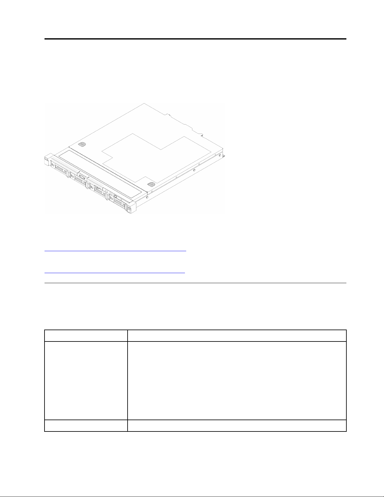
The ThinkSystem SR250 server is a 1U rack server designed for high-volume network transaction
processing. This high-performance, multi-core server is ideally suited for networking environments that
require superior processor performance, input/output (I/O) flexibility, and high manageability.
Figure 1. SR250
The server comes with a limited warranty. For details about the warranty, see:
https://support.lenovo.com/us/en/solutions/ht503310
For details about your specific warranty, see:
http://datacentersupport.lenovo.com/warrantylookup
Specifications
The following information is a summary of the features and specifications of the server. Depending on the
model, some features might not be available, or some specifications might not apply.
Table 1. Server Specifications
Specification
Size
Weight Maximum: 12.3 kg (27.1 lbs)
Description
1U rack
• Height: 43.0 mm (1.7 inches)
• Width: 434.4 mm (17.1 inches)
– With rack handles: 481.7 mm (18.9 inches)
– Without rack handles: 434.4 mm (17.1 inches)
• Depth: 497.8 mm (19.6 inches)
Note: The depth is measured from the front mounting flange of the rack to the
rear of the server.
© Copyright Lenovo 2018 1
Table 1. Server Specifications (continued)
Specification
Processor (depending on the
model)
Memory
Drive bays (depending on the
model)
Description
One Intel® multi-core processor from Core™, Pentium®, Celeron® or Xeon® E
processor family
Notes:
1. Use the Setup utility to determine the type and speed of the processors in the
node.
2. For a list of supported processors, see
serverproven/
.
http://www.lenovo.com/us/en/
3. If the 95 W processor is used, the server only supports the eight 2.5-inch hotswap drive backplane.
• Slots: 4 DIMM slots
• Minimum: 8 GB (1 x 8GB DIMM)
• Maximum: 64 GB (4 x 16GB DIMM)
• Type:
– PC4-21300, 2666 MT/s, error correcting code (ECC), double-data-rate 4
(DDR4) unbuffered DIMM (UDIMM)
Note: For a list of supported processors, see
serverproven/
.
http://www.lenovo.com/us/en/
• 2.5-inch models:
– Supports up to four simple-swap SAS/SATA drive bays.
– Supports up to eight hot-swap SAS/SATA drive bays.
– Supports up to ten hot-swap SAS/SATA drive bays with two NVMe drive bays.
• 3.5-inch models:
– Supports up to four simple-swap SAS/SATA drive bays.
– Supports up to four hot-swap SAS/SATA drive bays.
Notes:
1. When the eighth SATA drive is installed, the M.2 drive is disabled.
2. When all eight storage drives have been installed, and the system has been set
to software RAID mode in the UEFI settings, regardless if the disks are
configured as an array or as separate disks, drives 6 and 7 cannot be used to
install the Windows operating system.
3. If the M.2 drive has been installed, and the system has been set to software
RAID mode in the UEFI settings, regardless if the disks are configured as an
array or as separate disks, the M.2 drive cannot be used to install the Windows
operating system.
M.2 drive
Supports 2 different physical sizes of M.2 drives:
• 42 mm (2242)
• 80 mm (2280)
Notes:
1. When the eighth SATA drive is installed, the M.2 drive is disabled.
2. If the M.2 drive has been installed, and the system has been set to software
RAID mode in the UEFI settings, regardless if the disks are configured as an
array or as separate disks, the M.2 drive cannot be used to install the Windows
operating system.
2 ThinkSystem SR250 Maintenance Manual
Table 1. Server Specifications (continued)
Specification
PCIe riser cards and
expansion slots
Integrated functions
RAID controllers (depending
on the model)
Description
Up to two expansion slots (depending on the sever configuration):
• Slot 1-2: PCI Express 3.0 for PCIe -card with the following slots available
depending on the card installed:
1. x16 PCIe (full-height, half-length) kit provides:
– Slot 1: Not available
– Slot 2: PCI Express 3.0 x16
2. x8/x8 butterfly card:
– Slot 1: PCI Express 3.0 x8 (x8, x4, x1), low profile
– Slot 2: PCI Express 3.0 x8 (x8, x4, x1), full-height, half-length
• Slot 4 (on-board): PCI Express 3.0 x8 (x4, x1), low-profile
Notes:
1. PCIe slot 1 and slot 2 do not support ARI and SR-IOV.
2. PCIe slot 4 supports ARI and SR-IOV.
3. QLogic QL41262 PCIe 25Gb 2-Port SFP28 Ethernet Adapter does not support
shared storage V3700 V2/XP and V5030 V2 configurations.
• Lenovo XClarity Controller, which provides service processor control and
monitoring functions, video controller, and remote keyboard, video, mouse, and
remote drive capabilities.
• Light-path diagnostics
• Front standard connectors (front of server):
– One USB 2.0 connector
– One USB 3.1 Gen 1 connector
– One front operator panel
– One VGA connector (optional)
• Rear standard connectors (rear of server):
– Two USB 3.1 Gen 2 connectors
– Two Ethernet connectors
– One Lenovo XClarity Controller network connector
– One VGA connector
– One serial connector
Hardware RAID: Additional RAID levels supported when an optional RAID controller
is installed. The hardware RAID controller supports RAID levels 0, 1, 5, and 10.
Video controller (integrated
into Lenovo XClarity
Controller)
Software RAID: A software RAID controller is integrated on the system board. The
software RAID controller supports RAID levels 0, 1, 5, and 10.
Matrox G200
• ASPEED
• SVGA compatible video controller
• Avocent Digital Video Compression
• 16 MB of video memory (not expandable)
Note: Maximum video resolution is 1600 x 1200 at 75 Hz.
Chapter 1. Introduction 3
Table 1. Server Specifications (continued)
Specification
Fans
Power supplies
Acoustical noise emissions
(base configuration)
Description
Four internal system fans (40mm x 28mm)
One fixed power supply: 300-watt ac 80 PLUS Gold
Supports up to two power supplies for redundancy support: 450-watt ac 80 PLUS
Platinum
• Operation:
– Minimum: 5.3 bels
– Typical: 5.4 bels
– Maximum: 5.7 bels
• Idle
– Minimum: 4.9 bels
– Typical: 5.0 bels
– Maximum: 5.4 bels
Notes:
1. These sound power levels are measured in controlled acoustical environments
according to procedures specified by ISO 7779 and are reported in accordance
with ISO 9296.
2. The declared acoustic noise levels are based on specified configurations, which
may change slightly depending on configurations/conditions.
3. The options supported in this server vary in function, power consumption, and
required cooling. Any increase in cooling required by these options will increase
the fan speed and generated sound level. The actual sound pressure levels
measured in your installation depend upon a variety of factors, including: the
number of racks in the installation; the size, materials, and configuration of the
room; the noise levels of other equipment; the room ambient temperature and
barometric pressure; and the location of employees in relation to the equipment.
Heat output Approximate heat output:
• Minimum configuration: 287.46 BTU per hour (84.25 watts)
• Maximum configuration : 783.02 BTU per hour (229.49 watts)
4 ThinkSystem SR250 Maintenance Manual
Table 1. Server Specifications (continued)
Specification
Electrical input
Environment
Description
Sine-wave input (50–60 Hz) required
• 300-Watt power supply:
100-127 V ac /200-240 V ac, 4/2A
• 450-Watt power supply:
100-127 V ac /200-240 V ac, 5.8/2.9A
The ThinkSystem SR250 complies with ASHRAE class A2 specifications. System
performance may be impacted when operating temperature is outside ASHRAE A2
specification or fan failed condition.
The ThinkSystem SR250 is supported in the following environment:
• Air temperature:
– Server on:
– (ASHRAE Class A2): 10°C to 35°C (50°F to 95°F); decrease the maximum
ambient temperature by 1°C for every 300 m (984 ft) increase in altitude
above 900 m (2,953 ft).
– Sever off: 5°C to 45°C (41°F to 113°F)
– Shipping/storage: -40 - 60°C (-40 - 140°F)
• Maximum altitude: 3050 m (10 000 ft)
• Relative Humidity (non-condensing):
– Operating:
– ASHRAE Class A2: 8% - 80%, maximum dew point : 21°C (70°F)
– Shipment/storage: 8% to 90%
• ASHRAE A3 is supported for the eight 2.5-inch hot-swap drive configuration with
80W processor only.
• Particulate contamination:
Airborne particulates and reactive gases acting alone or in combination with other
environmental factors such as humidity or temperature might pose a risk to the
solution. For information about the limits for particulates and gases, see
“Particulate contamination” on page 170.
Firmware updates
Several options are available to update the firmware for the server.
You can use the tools listed here to update the most current firmware for your server and the devices that are
installed in the server.
Note: Lenovo typically releases firmware in bundles called UpdateXpress System Packs (UXSPs). To ensure
that all of the firmware updates are compatible, you should update all firmware at the same time. If you are
updating firmware for both the Lenovo XClarity Controller and UEFI, update the firmware for Lenovo XClarity
Controller first.
Best practices related to updating firmware is available at the following location:
http://lenovopress.com/LP0656
Chapter 1. Introduction 5

Important terminology
• In-band update. The installation or update is performed using a tool or application within an operating
system that is executing on the server’s core CPU.
• Out-of-band update. The installation or update is performed by the Lenovo XClarity Controller collecting
the update and then directing the update to the target subsystem or device. Out-of-band updates have no
dependency on an operating system executing on the core CPU. However, most out-of-band operations
do require the server to be in the S0 (Working) power state.
• On-Target update. The installation or update is initiated from an Operating System executing on the
server’s operating system.
• Off-Target update. The installation or update is initiated from a computing device interacting directly with
the server’s Lenovo XClarity Controller.
• UpdateXpress System Packs (UXSPs). UXSPs are bundled updates designed and tested to provide the
interdependent level of functionality, performance, and compatibility. UXSPs are server machine-type
specific and are built (with firmware and device driver updates) to support specific Windows Server, Red
Hat Enterprise Linux (RHEL) and SUSE Linux Enterprise Server (SLES) operating system distributions.
Machine-type-specific firmware-only UXSPs are also available.
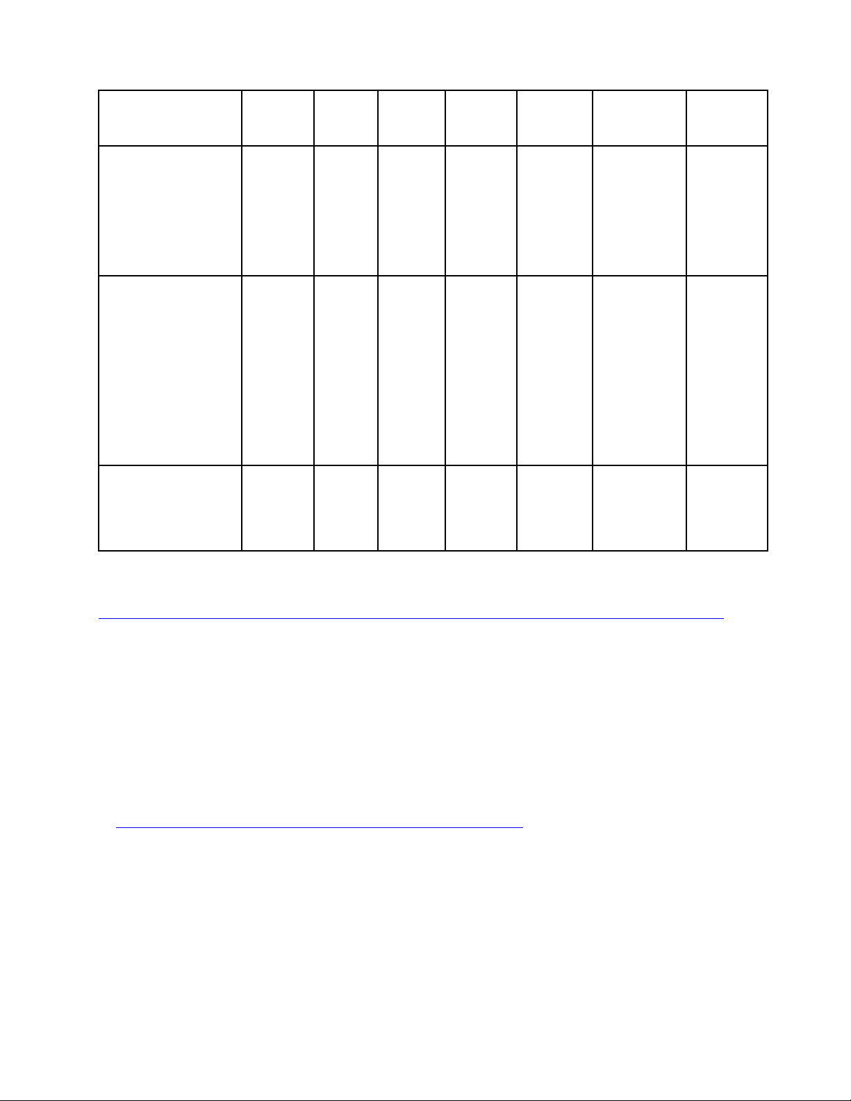
See the following table to determine the best Lenovo tool to use for installing and setting up the firmware:
Note: The server UEFI settings for option ROM must be set to Auto or UEFI to update firmware using
Lenovo XClarity Administrator or Lenovo XClarity Essentials. For more information, see the following Tech
Tip:
https://datacentersupport.lenovo.com/us/en/solutions/ht506118
Tool
Lenovo XClarity
Provisioning
Manager
Limited to core system
firmware only.
Lenovo XClarity
Controller
Supports core system
firmware and most
advanced I/O option
firmware updates
Lenovo XClarity
Essentials OneCLI
Supports all core
system firmware, I/O
firmware, and installed
operating system
driver updates
Out-ofIn-band
update
√ √ √ √
√ √ √ √
band
update
√ √ √ √
Ontarget
update
Offtarget
update
Graphical
user
interface
Commandline interface
Supports
UXSPs
6 ThinkSystem SR250 Maintenance Manual
Tool
Lenovo XClarity
Essentials
UpdateXpress
Supports all core
system firmware, I/O
firmware, and installed
operating system
driver updates
Out-ofIn-band
update
√ √ √ √
band
update
Ontarget
update
Offtarget
update
Graphical
user
interface
Commandline interface
Supports
UXSPs
Lenovo XClarity
Essentials Bootable
Media Creator
Supports core system
firmware and I/O
firmware updates. You
can update the
Microsoft Windows
operating system, but
device drivers are not
included on the
bootable image
Lenovo XClarity
Administrator
Supports core system
firmware and I/O
firmware updates
√ √ √ √
√ √ √ √
The latest firmware can be found at the following site:
http://datacentersupport.lenovo.com/us/en/products/servers/system-x/system-x3850-x6/6241/downloads
• Lenovo XClarity Provisioning Manager
From Lenovo XClarity Provisioning Manager, you can update the Lenovo XClarity Controller firmware, the
UEFI firmware, and the Lenovo XClarity Provisioning Manager software.
Note: By default, the Lenovo XClarity Provisioning Manager Graphical User Interface is displayed when
you press F1. If you have changed that default to be the text-based system setup, you can bring up the
Graphical User Interface from the text-based system setup interface.
Additional information about using Lenovo XClarity Provisioning Manager to update firmware is available
at:
http://sysmgt.lenovofiles.com/help/topic/LXPM/platform_update.html
• Lenovo XClarity Controller
If you need to install a specific update, you can use the Lenovo XClarity Controller interface for a specific
server.
Notes:
– To perform an in-band update through Windows or Linux, the operating system driver must be installed
and the Ethernet-over-USB (sometimes called LAN over USB) interface must be enabled.
Additional information about configuring Ethernet over USB is available at:
Chapter 1. Introduction 7

http://sysmgt.lenovofiles.com/help/topic/com.lenovo.systems.management.xcc.doc/NN1ia_c_
configuringUSB.html
– If you update firmware through the Lenovo XClarity Controller, make sure that you have downloaded
and installed the latest device drivers for the operating system that is running on the server.
Specific details about updating firmware using Lenovo XClarity Controller are available at:
http://sysmgt.lenovofiles.com/help/topic/com.lenovo.systems.management.xcc.doc/NN1ia_c_
manageserverfirmware.html
• Lenovo XClarity Essentials OneCLI
Lenovo XClarity Essentials OneCLI is a collection of command line applications that can be used to
manage Lenovo servers.Its update application can be used to update firmware and device drivers for your
servers. The update can be performed within the host operating system of the server (in-band) or remotely
through the BMC of the server (out-of-band).
Specific details about updating firmware using Lenovo XClarity Essentials OneCLI is available at:
http://sysmgt.lenovofiles.com/help/topic/toolsctr_cli_lenovo/onecli_c_update.html
• Lenovo XClarity Essentials UpdateXpress
Lenovo XClarity Essentials UpdateXpress provides most of OneCLI update functions through a graphical
user interface (GUI). It can be used to acquire and deploy UpdateXpress System Pack (UXSP) update
packages and individual updates. UpdateXpress System Packs contain firmware and device driver
updates for Microsoft Windows and for Linux.
You can obtain Lenovo XClarity Essentials UpdateXpress from the following location:
https://datacentersupport.lenovo.com/solutions/lnvo-xpress
• Lenovo XClarity Essentials Bootable Media Creator
You can use Lenovo XClarity Essentials Bootable Media Creator to create bootable media that is suitable
for applying firmware updates, running preboot diagnostics, and deploying Microsoft Windows operating
systems.
You can obtain Lenovo XClarity Essentials BoMC from the following location:
https://datacentersupport.lenovo.com/solutions/lnvo-bomc
• Lenovo XClarity Administrator
If you are managing multiple servers using the Lenovo XClarity Administrator, you can update firmware for
all managed servers through that interface. Firmware management is simplified by assigning firmwarecompliance policies to managed endpoints. When you create and assign a compliance policy to managed
endpoints, Lenovo XClarity Administrator monitors changes to the inventory for those endpoints and flags
any endpoints that are out of compliance.
Specific details about updating firmware using Lenovo XClarity Administrator are available at:
http://sysmgt.lenovofiles.com/help/topic/com.lenovo.lxca.doc/update_fw.html
Configuring the LAN over USB interface manually
To perform a firmware update through the operating system using Lenovo XClarity Essentials OneCLI, the
Lenovo XClarity Controller must be configured to use the LAN over USB interface. The firmware update
package attempts to perform the setup automatically, if needed. If the automatic setup fails or if you prefer to
set up the LAN over USB manually, use one of the following procedures.
Additional information about using the Lenovo XClarity Controller to enable LAN over USB is available at:
8
ThinkSystem SR250 Maintenance Manual

http://sysmgt.lenovofiles.com/help/topic/com.lenovo.systems.management.xcc.doc/NN1ia_c_
configuringUSB.html
Installing the LAN over USB Windows device driver
When you install a Windows operating system, there might be an unknown RNDIS device in the Device
Manager. Lenovo provides a Windows INF file that identifies this device.
Complete the following steps to install ibm_rndis_server_os.inf:
Note: You only have to perform these steps if the compute node is running a Windows operating system
and the ibm_rndis_server_os.inf file has not been previously installed. The file only has to be installed once. It
is required by Windows operating systems to detect and use the LAN over USB functionality.
Step 1. Click Administrative Tools ➙ Computer Management ➙ Device Manager and find the RNDIS
Device. Click Properties ➙ Driver ➙ Reinstall driver. Point the server to the \Windows\inf
directory where it can find the ibm_rndis_server_os.inf file and install the device.
Step 2. Click Administrative Tools ➙ Device Manager. Right-click Network adapters and select Scan
for hardware changes. A small pop-up confirms that the Ethernet device is found and installed.
The New Hardware Wizard starts automatically.
Step 3. When you are prompted Can Windows connect to Windows Update to search for software?, select No,
not this time. Click Next to continue.
Step 4. When you are prompted What do you want the wizard to do?, select Install from a list or specific
location (Advanced). Click Next to continue.
Step 5. When you are prompted Please choose your search and installation options, select Don't search. I
will choose the driver to install. Click Next to continue.
Step 6. When you are prompted Select a hardware type, and then click Next, select Network adapters.
Click Next to continue.
Step 7. When you are prompted with the statement Completing the Found New Hardware Wizard, click Finish.
A new local area connection appears. If the message This connection has limited or no
connectivity is displayed, ignore this message.
Step 8. Return to the Device Manager. Lenovo USB Remote NDIS Network Device appears under
Network Adapters.
Step 9. Use the Lenovo XClarity Controller interface to view or set the IP address for the LAN adapter.
Additional information about using the Lenovo XClarity Controller to configure LAN over USB is
available at:
http://sysmgt.lenovofiles.com/help/topic/com.lenovo.systems.management.xcc.doc/NN1ia_c_
configuringUSB.html
Tech Tips
Lenovo continually updates the support website with the latest tips and techniques that you can use to solve
issues that you might have with your server. These Tech Tips (also called retain tips or service bulletins)
provide procedures to work around issues related to the operation of your server.
To find the Tech Tips available for your server:
1. Go to
2. Click How-tos & Solutions.
http://datacentersupport.lenovo.com and navigate to the support page for your server.
Expand Symptom to choose a category for the type is problem that you are having.
Chapter 1. Introduction 9

Security advisories
Lenovo is committed to developing products and services that adhere to the highest security standards in
order to protect our customers and their data. When potential vulnerabilities are reported, it is the
responsibility of the Lenovo Product Security Incident Response Team (PSIRT) to investigate and provide
information to our customers so they may put mitigation plans in place as we work toward providing
solutions.
The list of current advisories is available at the following site:
https://datacentersupport.lenovo.com/product_security/home
Power on the server
After the server performs a short self-test (power status LED flashes quickly) when connected to input power,
it enters a standby state (power status LED flashes once per second).
The server can be turned on (power LED on) in any of the following ways:
• You can press the power button.
• The server can restart automatically after a power interruption.
• The server can respond to remote power-on requests sent to the Lenovo XClarity Controller.
For information about powering off the server, see “Power off the server” on page 10.
Power off the server
The server remains in a standby state when it is connected to a power source, allowing the Lenovo XClarity
Controller to respond to remote power-on requests. To remove all power from the server (power status LED
off), you must disconnect all power cables.
To place the server in a standby state (power status LED flashes once per second):
Note: The Lenovo XClarity Controller can place the server in a standby state as an automatic response to a
critical system failure.
• Start an orderly shutdown using the operating system (if supported by your operating system).
• Press the power button to start an orderly shutdown (if supported by your operating system).
• Press and hold the power button for more than 4 seconds to force a shutdown.
When in a standby state, the server can respond to remote power-on requests sent to the Lenovo XClarity
Controller. For information about powering on the server, see “Power on the server” on page 10.
10
ThinkSystem SR250 Maintenance Manual
Chapter 2. Server components
Use the information in this section to learn about each of the components associated with your server.
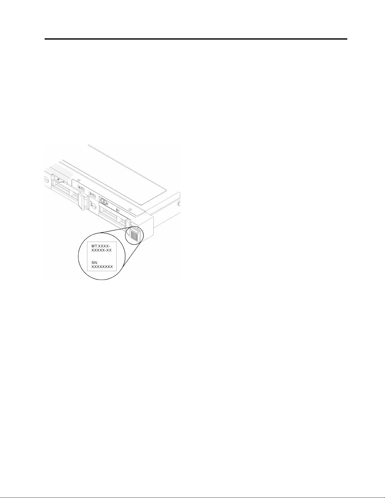
Identifying your server
When you contact Lenovo for help, the machine type, model, and serial number information helps support
technicians to identify your server and provide faster service.
The model number and serial number are on the ID label on the front of the server. The following illustration
shows the location of the ID label containing the machine type, model, and serial number.
Figure 2. Location of the machine type, model, and serial number
Network access tag
The network access tag can be found on the front of the server. You can pull way the network access tag to
paste your own label for recording some information such as the hostname, the system name and the
inventory bar code. Please keep the network access tag for future reference.
© Copyright Lenovo 2018 11
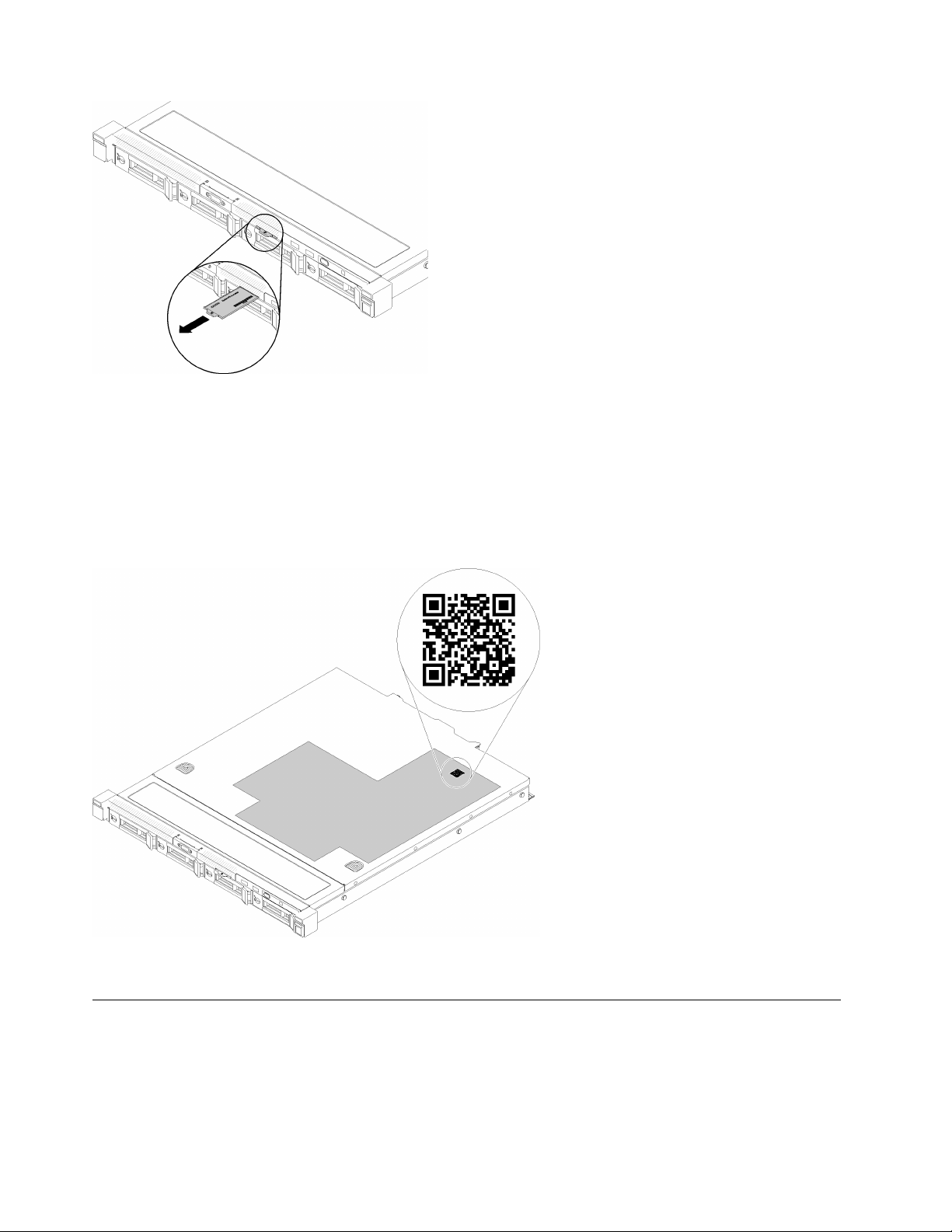
Figure 3. Network access tag
QR code
In addition, the system Service Card that is located on the top cover of the server, provides a quick reference
(QR) code for mobile access to service information. You can scan the QR code with a mobile device using a
QR code reader application and get quick access to the Service Information web page. The Service
Information web page provides additional information for parts installation and replacement videos, and error
codes for server support.
Figure 4. SR250 QR code
Front view
The front view of the server varies by the model.
12
ThinkSystem SR250 Maintenance Manual

Front view of the server
Figure 5. Four simple-swap drives model front view
Table 2. Components on the four simple-swap drives model front view
1 VGA connector (optional)
2 USB 2.0 connector 5 Four simple-swap drive bays (0-3)
3 USB 3.1 Gen 1 connector
4 Front operator panel
6 Rack release latches
Figure 6. Four hot-swap drives model front view
Table 3. Components on the four hot-swap drives model front view
1 VGA connector (optional)
2 USB 2.0 connector 5 Four hot-swap drive bays (0-3)
3 USB 3.1 Gen 1 connector
4 Front operator panel
6 Rack release latches
Figure 7. Eight 2.5-inch hot-swap drives model front view
Table 4. Components on the eight 2.5-inch hot-swap drives model front view
1 USB 2.0 connector 4 VGA connector (optional)
2 USB 3.1 Gen 1 connector 5 Eight 2.5-inch hot-swap drive bays (0-7)
3 Front operator panel 6 Rack release latches
Chapter 2. Server components 13
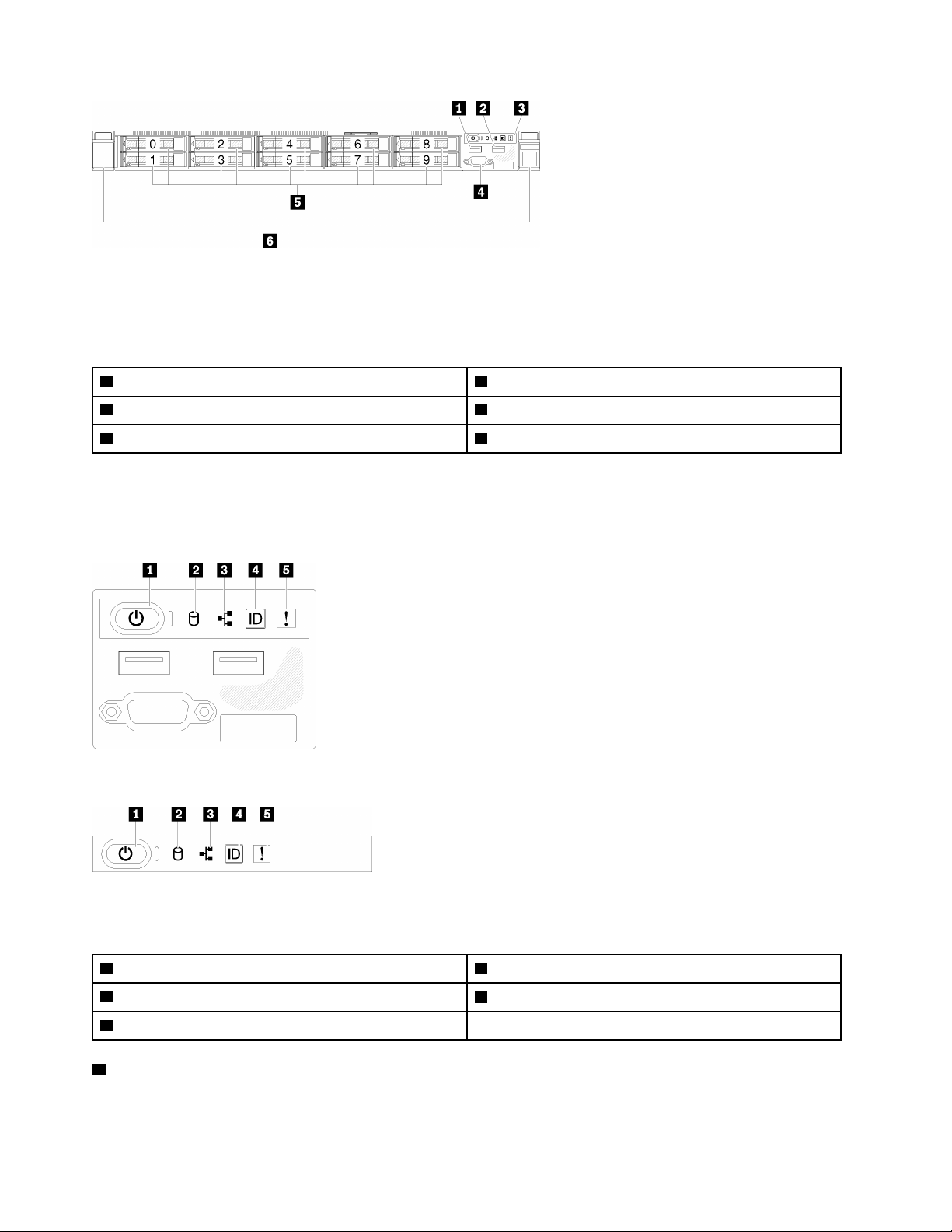
Figure 8. Ten 2.5-inch hot-swap drives model front view
Note: The last two drive bays may not be supported if only the eight-bay backplane is installed.
Table 5. Components on the ten 2.5-inch hot-swap drives model front view
1 USB 2.0 connector 4 VGA connector (optional)
2 USB 3.1 Gen 1 connector 5 Ten 2.5-inch hot-swap drive bays (0-9)
3 Front operator panel 6 Rack release latches
Front operator panel
The front operator information panel of the server provides controls, connectors, and LEDs. The front
operator panel varies by model.
Figure 9. 2.5-inch drive chassis front I/O assembly
Figure 10. 3.5-inch drive chassis front operator panel
Table 6. Front operator panel controls and indicators
1 Power button and power LED (green) 4 System ID button/LED (blue)
2 Drive activity LED (green) 5 System-error LED (yellow)
3 Network activity LED (green)
1 Power button and power LED (green): Press this button to turn the server on and off manually. The
states of the power LED are as follows:
Off: Power is not present or the power supply, or the LED itself has failed.
14
ThinkSystem SR250 Maintenance Manual
Flashing rapidly (4 times per second): The server is turned off and is not ready to be turned on. The
power button is disabled. This will last approximately 5 to 10 seconds.
Flashing slowly (once per second): The server is turned off and is ready to be turned on. You can press
the power button to turn on the server.
On: The server is turned on.
2 Drive activity LED (green): Each hot-swap drive comes with an activity LED. If the LED is lit, it indicates
that the drive is powered, but not actively reading or writing data. If the LED is flashing, the drive is being
accessed.
3 Network activity LED (green): When this LED flickers, it indicates that the server is transmitting to or
receiving signals from the Ethernet LAN.
4 System ID button/LED (blue): Use this blue LED to visually locate the server among other servers. This
LED is also used as a presence detection button. You can use Lenovo XClarity Administrator to light this LED
remotely.
5 System-error LED (yellow): When this yellow LED is lit, it indicates that a system error has occurred.
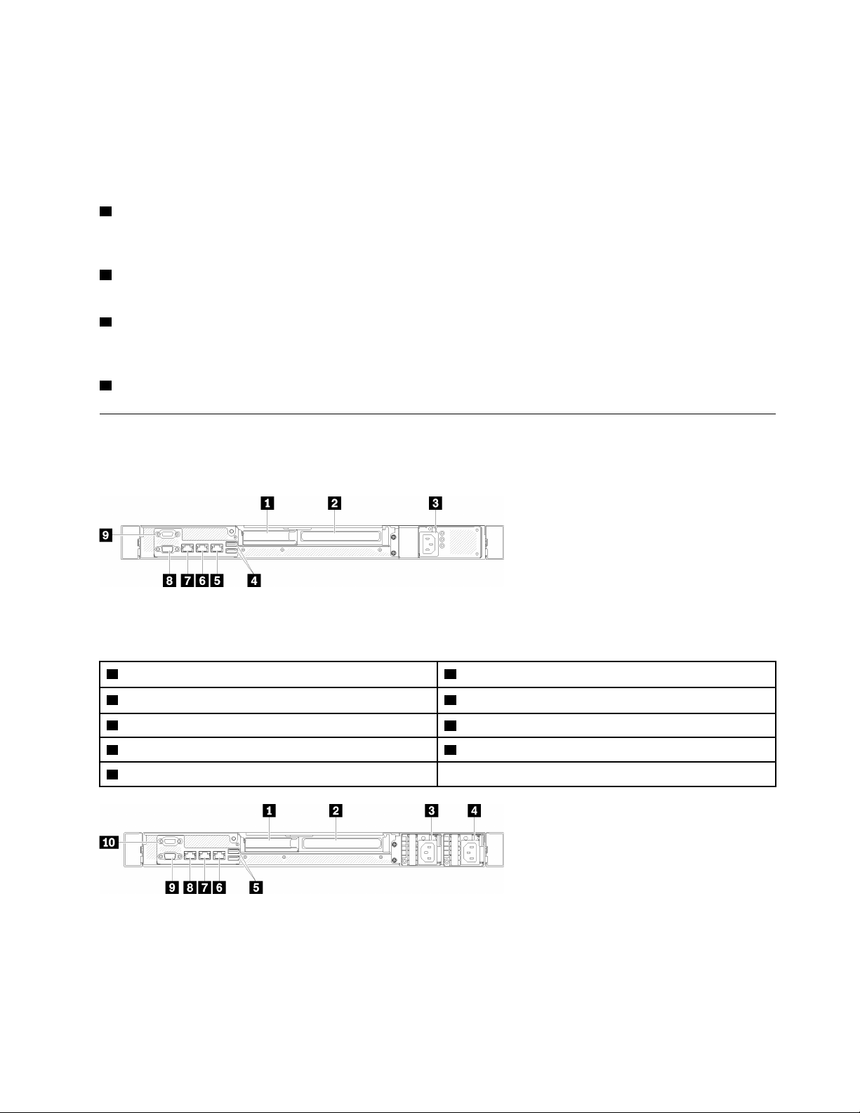
Rear view
The rear of the server provides access to several components, including the power supplies, PCIe adapters,
serial port, and Ethernet port.
Figure 11. Rear view - Non-redundant power supply model
Table 7. Rear view - Non-redundant power supply model
1 PCIe slot 1 6 Ethernet connector 1 (shared with XCC network port)
2 PCIe slot 2 7 Dedicated XClarity Controller (XCC) network connector
3 Power connector
4 USB 3.1 Gen 2 connectors 9 Serial connector
5 Ethernet connector 2
Figure 12. Rear view - Redundant power supply model
8 VGA connector
Chapter 2. Server components 15
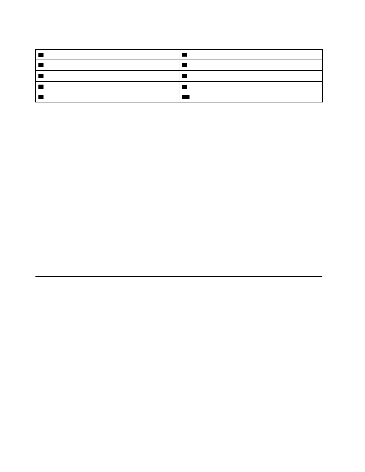
Table 8. Rear view - Redundant power supply model
1 PCIe slot 1
2 PCIe slot 2 7 Ethernet connector 1 (shared with XCC network port)
3 Power connector 1
4 Power connector 2
5 USB 3.1 Gen 2 connectors 10 Serial connector
6 Ethernet connector 2
8 Dedicated XClarity Controller (XCC) network connector
9 VGA connector
PCIe slot 1 and 2: Your server has PCIe slots on the system board for you to install appropriate PCIe
adapters. For information about the PCIe slots, see “PCIe riser assembly” on page 23.
Power connector 1 and 2: Connect the power cord to this component.
USB 3.1 Gen 2 connectors: Used to attach a device that requires a USB 3.1 connection, such as a
keyboard, a mouse, or a USB flash drive.
Ethernet connector 1 and 2: Used to attach an Ethernet cable for a LAN. Each Ethernet connector has two
status LEDs to help you identify the Ethernet connectivity and activity. If the LOM adapter is not installed,
Ethernet connector 1 can be set as XClarity Controller Network connector. To set Ethernet connector 1 as
XClarity Controller Network connector, start Setup Utility and select BMC Settings ➙ Network Settings ➙
Network Settings Network Interface Port : Shared. Then, click Shared NIC on and select Onboard Port
1.
Dedicated XClarity Controller (XCC) network connector : Used to attach an Ethernet cable to manage the
system using XClarity Controller.
VGA connector : Used to attach a VGA-compatible video device, such as a VGA monitor.
Serial connector: Connect a 9-pin serial device to this connector. The serial port is shared with the XCC.
The XCC can take control of the shared serial port to redirect serial traffic, using Serial over LAN (SOL).
System-board switches, jumpers, and buttons
The illustrations in this section provide information about the switches, jumpers, and buttons that are
available on the system board.
For more information about the LEDs that are available on the system board, see “System-board LEDs” on
page 16.
System-board LEDs
The following illustrations show the light-emitting diodes (LEDs) on the system board.
16
ThinkSystem SR250 Maintenance Manual
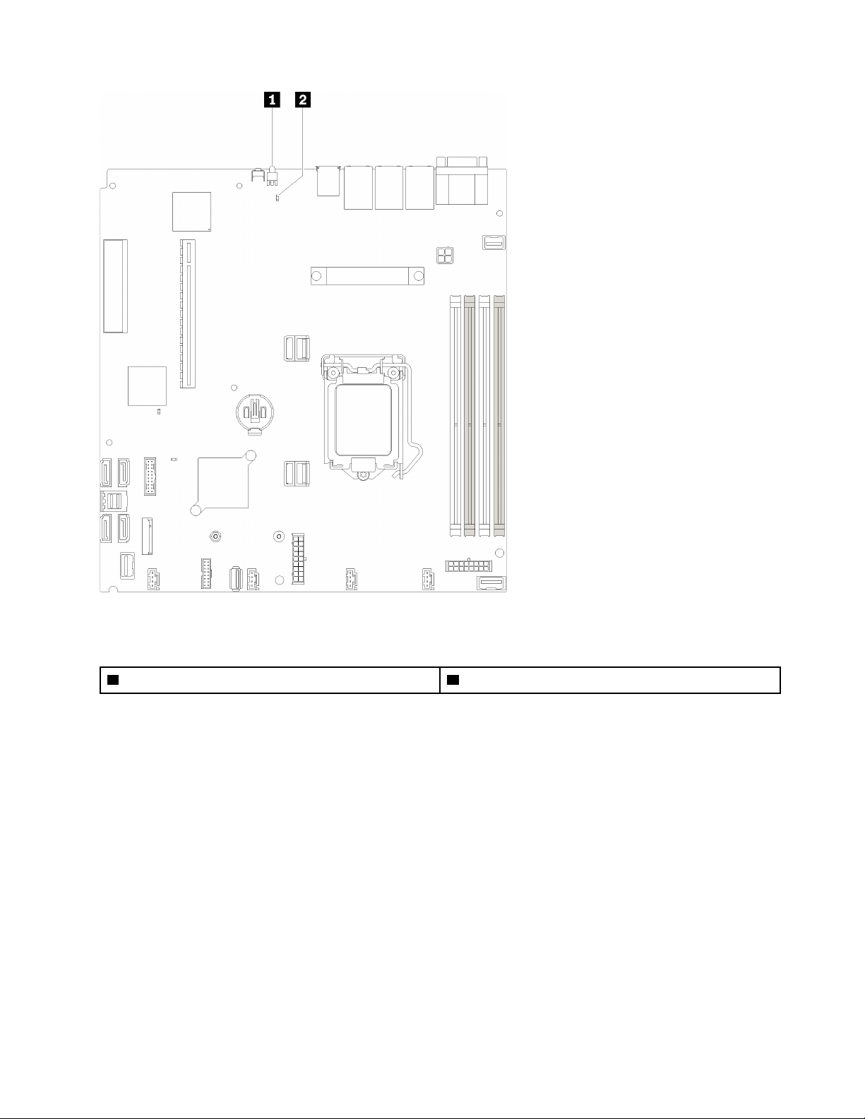
Figure 13. System-board LEDs
Table 9. System-board LEDs
1 Rear identification LED (blue) 2 System error LED (yellow)
System-board connectors
The following illustrations show the connectors on the system board.
Chapter 2. Server components 17
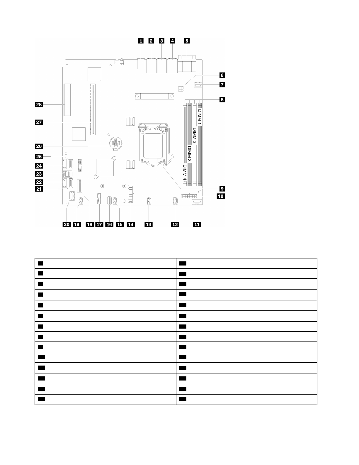
Figure 14. System-board connectors
Table 10. System-board connectors
1 USB 3.1 Gen 1 connector
2 Lan 2 connector
3 Lan 1 connector (shared with XCC) 17 TPM card/TPM connector
4 Dedicated XClarity Controller (XCC) network connector
5 VGA and serial port connector
6 Processor power connector 20 Front panel connector
7 Front VGA connector 21 SATA connector 6
8 DIMM slot 1-4
9 Processor
10 Backplane power connector
11 PIB signal connector
12 Fan 1 connector
13 Fan 2 connector 27 slot
14 System power connector 28 PCIe3x 8 (4,1) - slot 4
15 Fan 3 connector
16 Internal USB 3.1 Gen 1 connector
18 M.2 backplane connector
19 Fan 4 connector
22 SATA connector 7
23 SATA connector 0-3
24 SATA connector 4
25 SATA connector 5
26 CMOS battery - CR2032
18 ThinkSystem SR250 Maintenance Manual
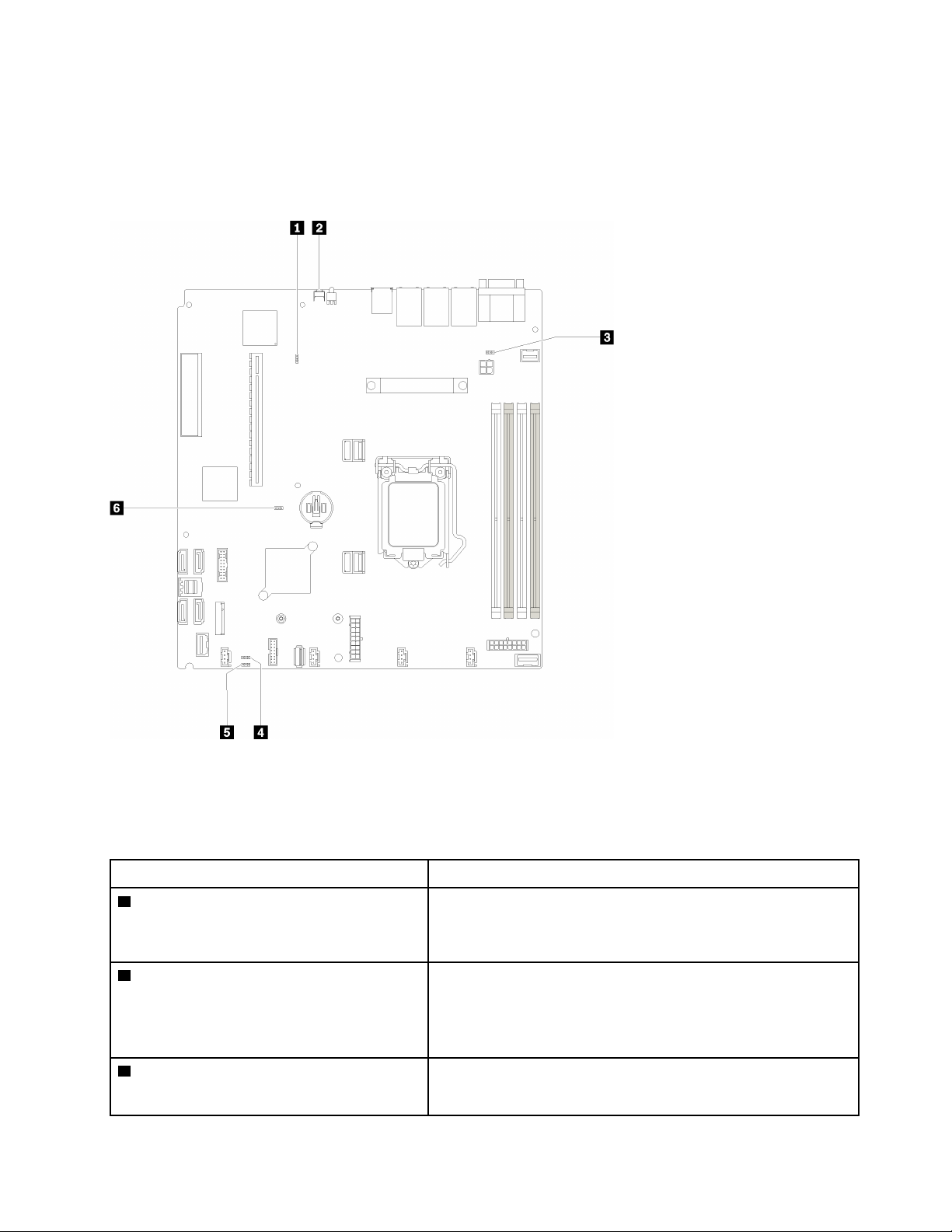
System-board jumpers and buttons
The following illustrations show the location of the jumpers and buttons on the server.
Note: If there is a clear protective sticker on the top of the switch blocks, you must remove and discard it to
access the switches.
Figure 15. System-board jumpers and buttons
The following table describes the jumpers and buttons on the system board.
Table 11. System-board jumpers and buttons
Jumper and button name Jumper setting / Button function
1 Force XCC update jumper
2 Force NMI button This button is on the rear of the server. Press this button to force a
3 NCSI functional header jumper
• Pins 1 and 2: Normal (default).
• Pins 2 and 3: Force the Lenovo XClarity Controller to update to
the latest version.
nonmaskable interrupt to the processor. You might have to use a
pen or the end of a straightened paper clip to press the button.
You can also use it to force a blue-screen memory dump (use this
button only when you are directed to do so by Lenovo Support).
• Pins 1 and 2: Normal (default).
• Pins 2 and 3: Disable
Chapter 2. Server components 19
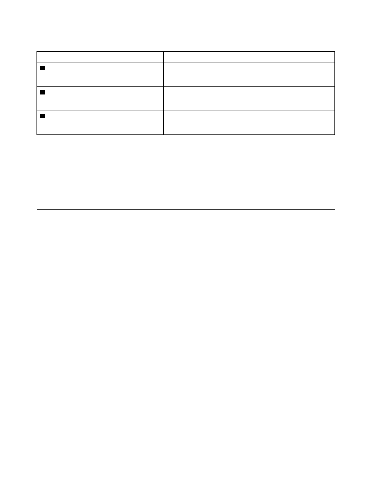
Table 11. System-board jumpers and buttons (continued)
Jumper and button name Jumper setting / Button function
4 Power permission override jumper
5 Clear CMOS jumper
6 TPM/TPM card physical presence jumper
• Pins 1 and 2: Normal (default).
• Pins 2 and 3: Override the power-on permission.
• Pins 1 and 2: Normal (default).
• Pins 2 and 3: Clear the real-time clock (RTC) registry.
• Pins 1 and 2: Normal (default).
• Pins 2 and 3: TPM/TPM card physical presence is asserted.
Important:
1. Before you change any switch settings or move any jumpers, turn off the server; then, disconnect all
power cords and external cables. Review the information in
safety_documentation/pdf_files.html
, “Installation Guidelines” on page 47, “Handling static-sensitive
http://thinksystem.lenovofiles.com/help/topic/
devices” on page 49, and “Power off the server” on page 10.
2. Any system-board switch or jumper block that is not shown in the illustrations in this document are
reserved.
RAID adapters and the NVMe switch card
Use this information to locate the connectors on the RAID adapters and the NVMe switch card.
20
ThinkSystem SR250 Maintenance Manual
Connectors on RAID adapters and the NVMe switch card
Figure 16. Connectors on RAID adapters and the NVMe switch card
Table 12. Connectors on RAID adapters and the NVMe switch card
1 SATA/SAS RAID adapter (8i) with two SATA/SAS
connectors (C0, C1)
2 SATA/SAS RAID adapter (16i) with four SATA/SAS
connectors (C0, C1, C2, C3)
3 PCIe switch card with four connectors (C0, C1, C2, C3)
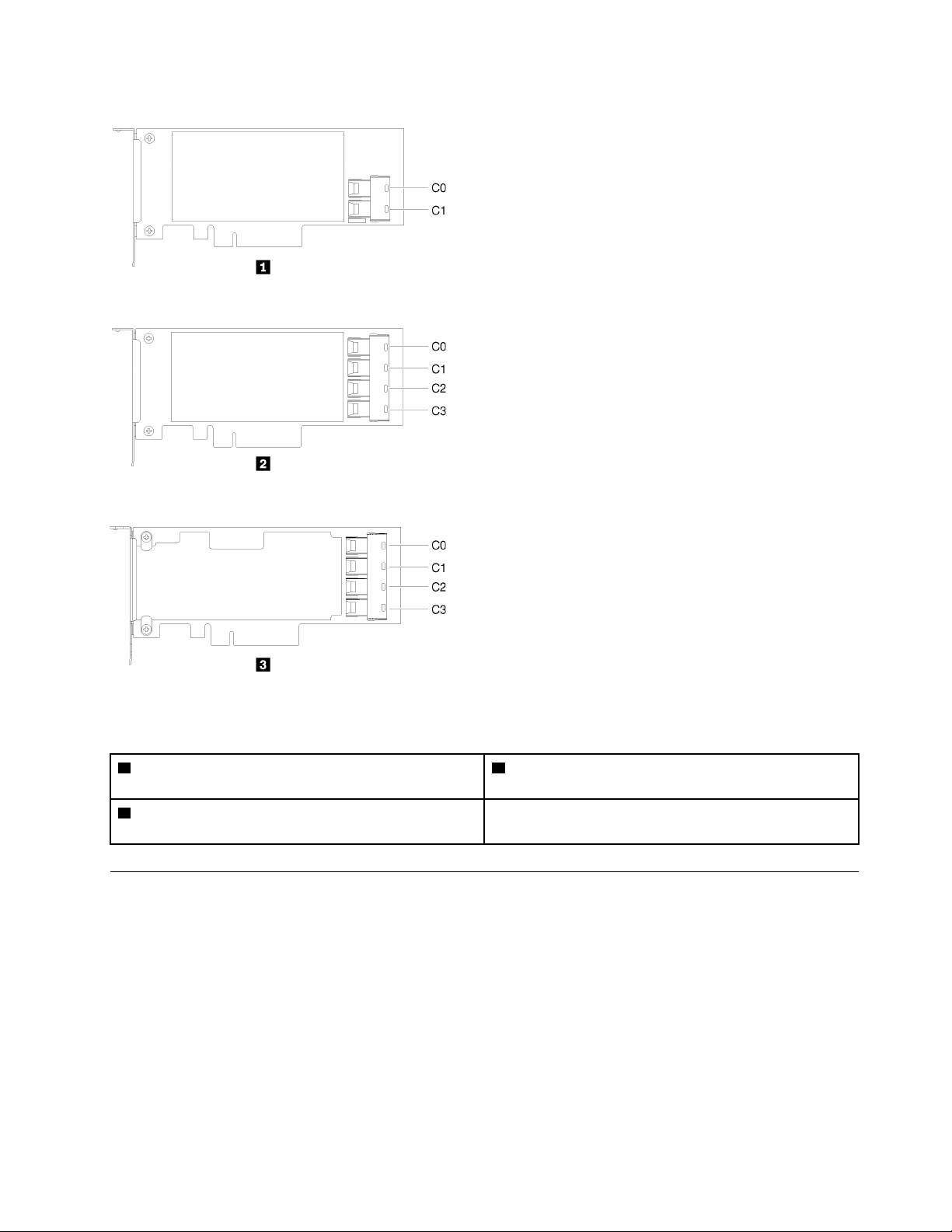
Backplates and backplanes
Use this information to identify the backplate or the backplane you use.
Chapter 2. Server components 21
Backplate, four 3.5-inch simple-swap drives (connects to RAID adapter)
Figure 17. Backplate, four 3.5-inch simple-swap drives (connects to RAID adapter)
Backplate, four 3.5-inch simple-swap drives (connects to onboard connectors)
Figure 18. Backplate, four 3.5-inch simple-swap drives (connects to onboard connectors)
Backplane, four 3.5-inch hot-swap drives
Figure 19. Backplane, four 3.5-inch hot-swap drives
22 ThinkSystem SR250 Maintenance Manual

Backplane, eight 2.5-inch hot-swap drives
Figure 20. Backplane, eight 2.5-inch hot-swap drives
Backplane, ten 2.5-inch hot-swap drives
Figure 21. Backplane, ten 2.5-inch hot-swap drives
Note: If the 95 W processor is used, the server does not support the ten 2.5-inch hot-swap drive backplane.
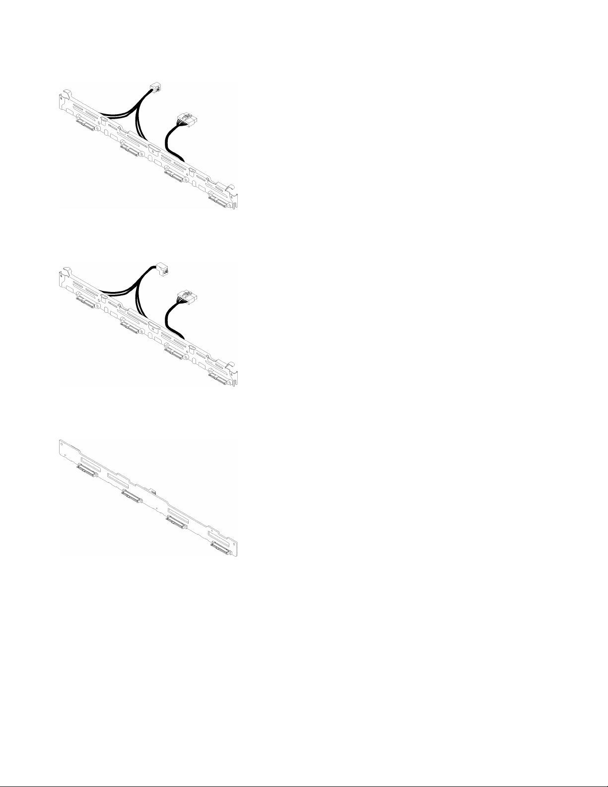
PCIe riser assembly
Use this information to locate the connectors on the PCIe riser assembly.
x16 PCIe riser assembly
Figure 22. x16 PCIe riser assembly
Table 13. x16 PCIe riser assembly
1 Slot 2, PCIe 3 x16, Full height, half-length
Chapter 2. Server components 23
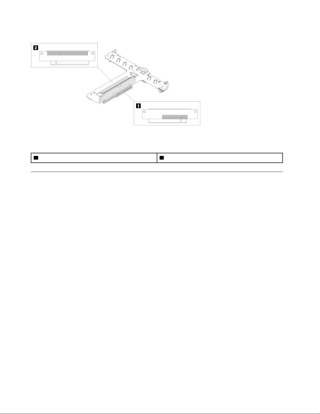
x8/x8 Butterfly riser assembly
Figure 23. x8/x8 Butterfly riser assembly
Table 14. x8/x8 Butterfly riser assembly
1 Slot 1, PCIe 3 x8, low profile 2 Slot 2, PCIe 3 x8, full-height, half-length
Internal cable routing
Some of the components in the server have internal cables and cable connectors.
Note: Disengage all latches, release tabs, or locks on cable connectors when you disconnect cables from
the system board. Failing to release them before removing the cables will damage the cable sockets on the
system board, which are fragile. Any damage to the cable sockets might require replacing the system board.
Some options, such as RAID controllers, might require additional internal cabling. See the documentation
that is provided for the option to determine any additional cabling requirements and instructions.
Front VGA cable
Use the section to understand the internal routing and connectors for the front video graphic adapter (VGA)
cable.
24
ThinkSystem SR250 Maintenance Manual

3.5-inch HDD model
Figure 24. Front VGA cable routing with four drives
Chapter 2. Server components 25
2.5-inch HDD model
Figure 25. Front VGA cable routing with ten drives
Fan cable
Use the section to understand the internal routing and connectors for fan cables.
26
ThinkSystem SR250 Maintenance Manual
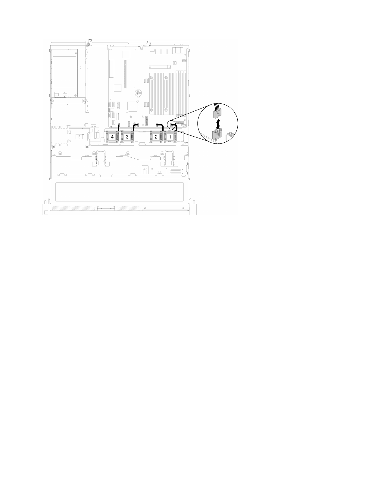
Figure 26. Fan cable routing
Power supply
Use the section to understand the internal routing and connectors for the power supply cables.
Chapter 2. Server components 27

Fixed power supply unit cable routing
Figure 27. Fixed power supply unit cable routing
Table 15. Fixed power supply unit cable routing
1 Processor power connector
2 System-board power connector
28 ThinkSystem SR250 Maintenance Manual

Hot-swap power supply unit cable routing
Figure 28. Hot-swap power supply unit cable routing
Table 16. Hot-swap power supply unit cable routing
1 Processor power connector
2 PIB signal connector
3 System-board power connector
Flash power module
Use the section to understand the internal routing and connectors for the flash power module.
Chapter 2. Server components 29

Figure 29. Flash power module cable routing
Table 17. Flash power module cable routing
1 Flash power module
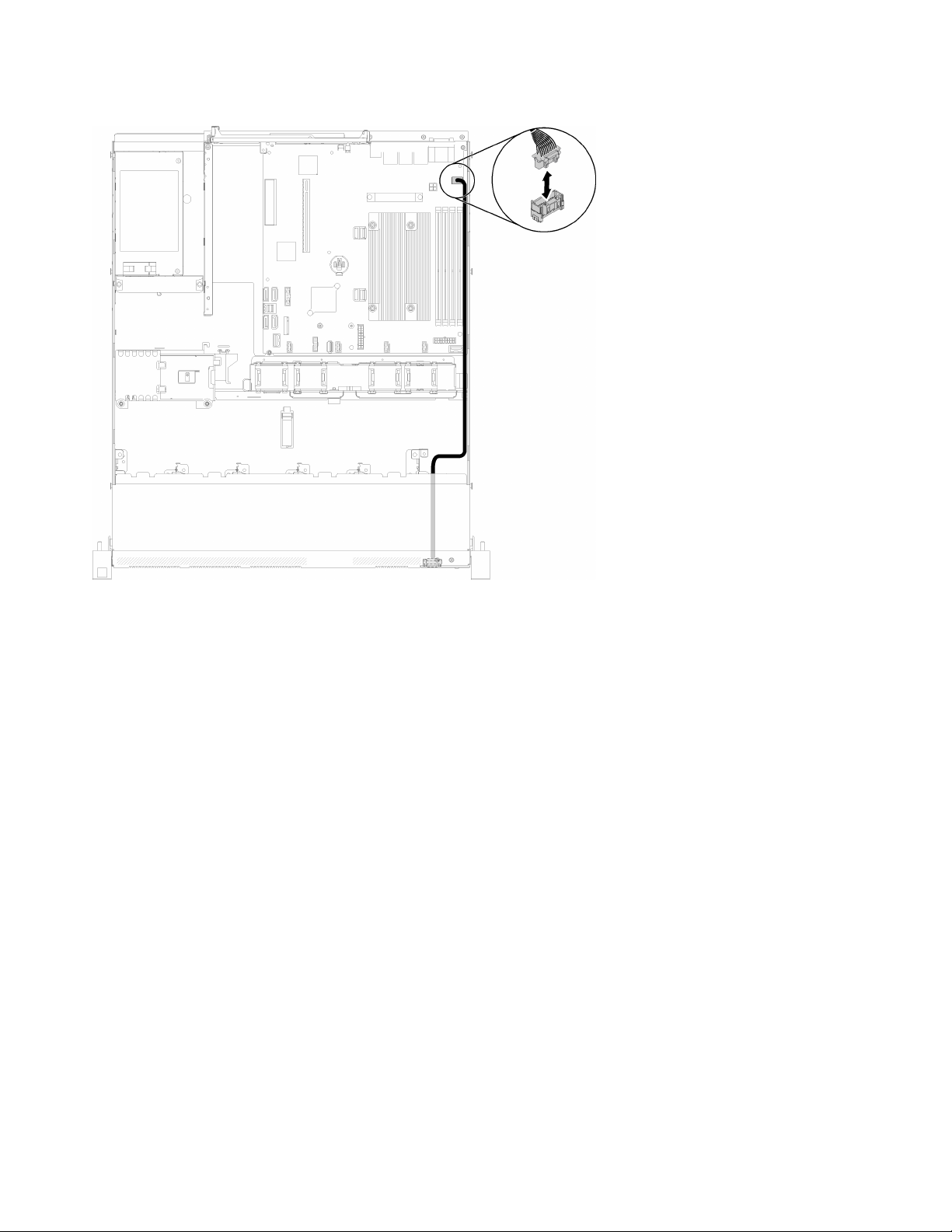
3.5-inch simple-swap drive model
Use this section to understand how to route cables for the 3.5-inch simple-swap drive models.
3.5-inch simple-swap drive model with software RAID
If you are implementing RAID through software, route the SAS cables and power cables as shown in the
following illustration.
30
ThinkSystem SR250 Maintenance Manual

Figure 30. 3.5-inch simple-swap drive model with software RAID
Table 18. 3.5-inch simple-swap drive model with software RAID
1 Backplane power connector
3.5-inch simple-swap drive model with hardware RAID
If you are implementing RAID through hardware, route the SAS cables and power cables as shown in the
following illustration.
Chapter 2. Server components 31
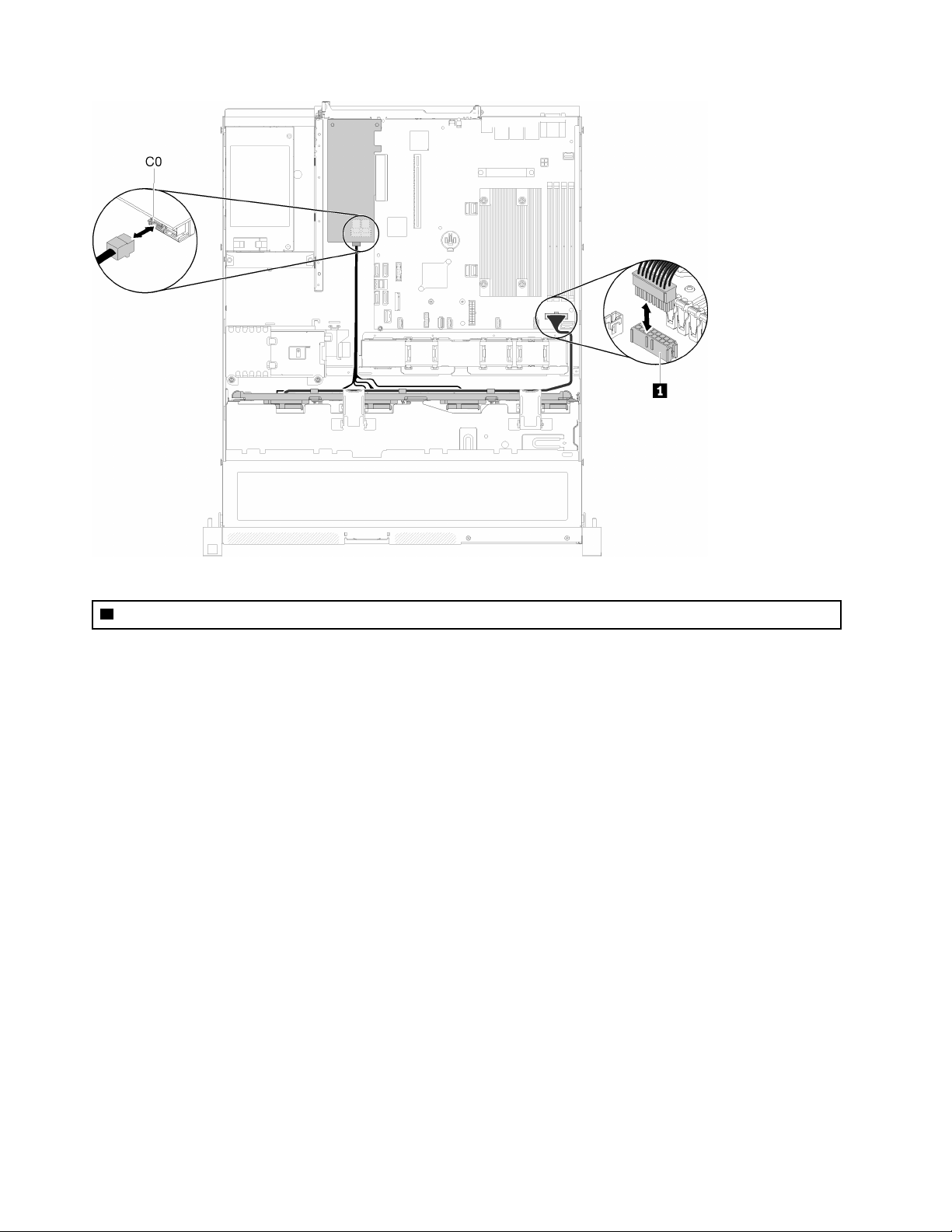
Table 19. 3.5-inch simple-swap drive model with hardware RAID
1 Backplane Power connector
Figure 31. 3.5-inch simple-swap drive model with hardware RAID
Four 3.5-inch hot-swap drive model
Use this section to understand how to route cables for the four 3.5-inch hot-swap drive model.
Four 3.5-inch hot-swap drive model with software RAID
If you are implementing RAID through software, route the SAS cables and power cables as shown in the
following illustration.
32
ThinkSystem SR250 Maintenance Manual

Figure 32. Four 3.5-inch hot-swap drive model with software RAID
Table 20. Four 3.5-inch hot-swap drive model with software RAID
1 Backplane power connector
Four 3.5-inch hot-swap drive model with hardware RAID
If you are implementing RAID through hardware, route the SAS cables and power cables as shown in the
following illustration.
Chapter 2. Server components 33

Table 21. Four 3.5-inch hot-swap drive model with hardware RAID
1 Backplane power connector
Figure 33. Four 3.5-inch hot-swap drive model with hardware RAID
Eight 2.5-inch hot-swap drive model
Use this section to understand how to route cables for the eight 2.5-inch hot-swap drive model.
Eight 2.5-inch hot-swap drive model with software RAID
If you are implementing RAID through software, route the SAS cables and power cables as shown in the
following illustration.
34
ThinkSystem SR250 Maintenance Manual

Figure 34. Eight 2.5-inch hot-swap drive model with software RAID
Table 22. Eight 2.5-inch hot-swap drive model with software RAID
1 Backplane power connector
Eight 2.5-inch hot-swap drive model with hardware RAID
If you are implementing RAID through hardware, route the SAS cables and power cables as shown in the
following illustration.
Chapter 2. Server components 35
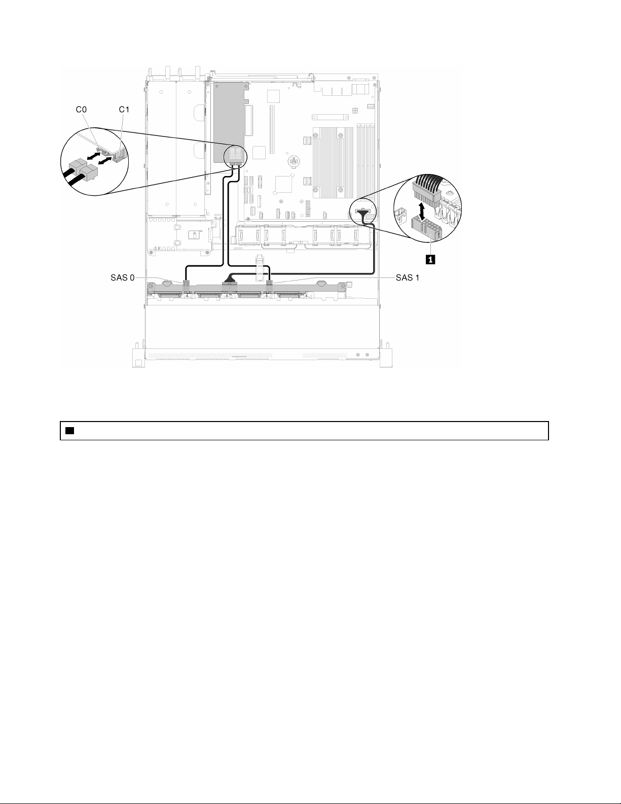
Figure 35. Eight 2.5-inch hot-swap drive model with hardware RAID
Table 23. Eight 2.5-inch hot-swap drive model with hardware RAID
1 Backplane power connector
Ten 2.5-inch hot-swap drive model
Use this section to understand how to route cables for the ten 2.5-inch hot-swap drive model.
Ten 2.5-inch hot-swap drive model with hardware RAID
If you are implementing RAID through hardware, route the SAS cables and power cables as shown in the
following illustration.
36
ThinkSystem SR250 Maintenance Manual
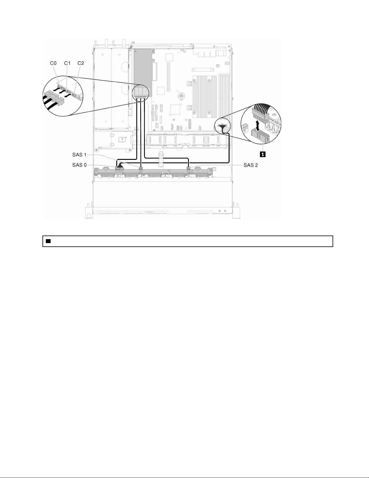
Table 24. Ten 2.5-inch hot-swap drive model with hardware RAID
1 Backplane power connector
Figure 36. Ten 2.5-inch hot-swap drive model with hardware RAID
Chapter 2. Server components 37

Ten 2.5-inch hot-swap drive model (two NVMe drives supported)
Figure 37. Ten 2.5-inch hot-swap drive model (two NVMe drives supported)
Table 25. Ten 2.5-inch hot-swap drive model (two NVMe drives supported)
1 Backplane power connector
Parts list
Use the parts list to identify each of the components that are available for your server.
For more information about ordering the parts shown in the Figure 38 “Server components - 2.5-inch drive
model” on page 40:
http://datacentersupport.lenovo.com/us/en/products/servers/thinksystem/sr250/7Y51/parts
Note: Depending on the model, your server might look slightly different from the illustration.
38
ThinkSystem SR250 Maintenance Manual

The parts listed in the following table are identified as one of the following:
• Tier 1 customer replaceable unit (CRU): Replacement of Tier 1 CRUs is your responsibility. If Lenovo
installs a Tier 1 CRU at your request with no service agreement, you will be charged for the installation.
• Tier 2 customer replaceable unit: You may install a Tier 2 CRU yourself or request Lenovo to install it, at
no additional charge, under the type of warranty service that is designated for your server.
• Field replaceable unit (FRU): FRUs must be installed only by trained service technicians.
• Consumable and Structural parts: Purchase and replacement of consumable and structural parts
(components, such as a cover or bezel) is your responsibility. If Lenovo acquires or installs a structural
component at your request, you will be charged for the service.
Chapter 2. Server components 39

2.5-inch drive model
Figure 38. Server components - 2.5-inch drive model
40 ThinkSystem SR250 Maintenance Manual

Table 26. Parts listing - 2.5-inch drive model
Index Description
Tier 1 CRU Tier 2 CRU
FRU
Consumable and
Structural
part
For more information about ordering the parts shown in Figure 38 “Server components - 2.5-inch drive model” on
page 40:
http://datacentersupport.lenovo.com/us/en/products/servers/thinksystem/sr250/7Y51/parts
1
2
3
4
5
6
7
8
9
10
11
12
13
14
15
16
17
18
19
20
21
22
23
24
25
Top cover
PCIe riser assembly
SATA/SAS RAID adapter (8i)
SATA/SAS RAID adapter (16i)
PCIe switch card
Air baffle
Fan
TPM card
System board
Fixed power supply unit
Redundant power supply unit
Chassis for the redundant power supply
Front I/O assembly
VGA cable
2.5-inch hot-swap drive
Drive filler
Chassis for the fixed power supply
Power interface board
Flash power module
M.2 drives (42 mm and 80mm)
DIMM
Processor
Heat sink
Backplane, eight 2.5-inch hot-swap drives
Backplane, ten 2.5-inch hot-swap drives
√
√
√
√
√
√
√
√
√
√
√
√
√
√
√
√
√
√
√
√
√
√
√
√
√
3.5-inch drive model
For more information about ordering the parts shown in Figure 39 “Server components - 3.5-inch drive
model” on page 42:
http://datacentersupport.lenovo.com/us/en/products/servers/thinksystem/sr250/7Y51/parts
Chapter 2. Server components 41

Note: Depending on the model, your server might look slightly different from the illustration.
Figure 39. Server components - 3.5-inch drive model
42 ThinkSystem SR250 Maintenance Manual

Table 27. Parts listing - 3.5-inch drive model
Index Description
Tier 1 CRU Tier 2 CRU
FRU
Consumable and
Structural
part
For more information about ordering the parts shown in Figure 39 “Server components - 3.5-inch drive model” on
page 42:
http://datacentersupport.lenovo.com/us/en/products/servers/thinksystem/sr250/7Y51/parts
1
2
3
4
5
6
7
8
9
10
11
12
13
14
15
16
17
Top cover
PCIe riser assembly
SATA/SAS RAID adapter (8i)
SATA/SAS RAID adapter (16i)
PCIe switch card
Air baffle
Fan
TPM card
System board
Fixed power supply unit
Redundant power supply unit
Chassis for the redundant power supply
Front operator panel
VGA cable
3.5-inch hot-swap drive
3.5-inch simple-swap drive
2.5-inch simple-swap drive with 3.5-inch drive
√
√
√
√
√
√
√
√
√
√
√
√
√
√
tray
√
√
√
18
19
20
21
22
23
24
25
26
27
Chassis for the fixed power supply
Power interface board
Flash power module
M.2 drives (42 mm and 80mm)
DIMM
Processor
Heat sink
Backplane, four 3.5-inch hot-swap drives
Backplate, four 3.5-inch simple-swap drives
(connects to RAID card)
Backplate, four 3.5-inch simple-swap drives
(connects to onboard connectors)
√
√
√
√
√
√
√
√
√
√
Chapter 2. Server components 43

44 ThinkSystem SR250 Maintenance Manual

Power cords
Several power cords are available, depending on the country and region where the server is installed.
To view the power cords that are available for the server:
1. Go to:
http://dcsc.lenovo.com/#/
2. Click Preconfigured Model or Configure to order.
3. Enter the machine type and model for your server to display the configurator page.
4. Click Power ➙ Power Cables to see all line cords.
Notes:
• For your safety, a power cord with a grounded attachment plug is provided to use with this product. To
avoid electrical shock, always use the power cord and plug with a properly grounded outlet.
• Power cords for this product that are used in the United States and Canada are listed by Underwriter's
Laboratories (UL) and certified by the Canadian Standards Association (CSA).
• For units intended to be operated at 115 volts: Use a UL-listed and CSA-certified cord set consisting of a
minimum 18 AWG, Type SVT or SJT, three-conductor cord, a maximum of 15 feet in length and a parallel
blade, grounding-type attachment plug rated 15 amperes, 125 volts.
• For units intended to be operated at 230 volts (U.S. use): Use a UL-listed and CSA-certified cord set
consisting of a minimum 18 AWG, Type SVT or SJT, three-conductor cord, a maximum of 15 feet in length
and a tandem blade, grounding-type attachment plug rated 15 amperes, 250 volts.
• For units intended to be operated at 230 volts (outside the U.S.): Use a cord set with a grounding-type
attachment plug. The cord set should have the appropriate safety approvals for the country in which the
equipment will be installed.
• Power cords for a specific country or region are usually available only in that country or region.
Chapter 2. Server components 45

46 ThinkSystem SR250 Maintenance Manual

Chapter 3. Hardware replacement procedures
This section provides installation and removal procedures for all serviceable system components. Each
component replacement procedure references any tasks that need to be performed to gain access to the
component being replaced.
For more information about ordering parts:
http://datacentersupport.lenovo.com/us/en/products/servers/thinksystem/sr250/7Y51/parts
Note: If you replace a part, such as an adapter, that contains firmware, you might also need to update the
firmware for that part. For more information about updating firmware, see “Firmware updates” on page 5.
Installation Guidelines
Before installing components in your server, read the installation guidelines.
Before installing optional devices, read the following notices carefully:
Attention: Prevent exposure to static electricity, which might lead to system halt and loss of data, by
keeping static-sensitive components in their static-protective packages until installation, and handling these
devices with an electrostatic-discharge wrist strap or other grounding system.
• Read the safety information and guidelines to ensure that you work safely.
– A complete list of safety information for all products is available at:
http://thinksystem.lenovofiles.com/help/topic/safety_documentation/pdf_files.html
– The following guidelines are available as well: “Handling static-sensitive devices” on page 49 and
“Working inside the server with the power on” on page 49.
• Make sure the components you are installing are supported by the server. For a list of supported optional
components for the server, see
• When you install a new server, download and apply the latest firmware. This will help ensure that any
known issues are addressed, and that your server is ready to work with optimal performance. Go to
ThinkSystem SR250 Drivers and Software to download firmware updates for your server.
Important: Some cluster solutions require specific code levels or coordinated code updates. If the
component is part of a cluster solution, verify that the latest level of code is supported for the cluster
solution before you update the code.
• It is good practice to make sure that the server is working correctly before you install an optional
component.
• Keep the working area clean, and place removed components on a flat and smooth surface that does not
shake or tilt.
• Do not attempt to lift an object that might be too heavy for you. If you have to lift a heavy object, read the
following precautions carefully:
– Make sure that you can stand steadily without slipping.
– Distribute the weight of the object equally between your feet.
– Use a slow lifting force. Never move suddenly or twist when you lift a heavy object.
– To avoid straining the muscles in your back, lift by standing or by pushing up with your leg muscles.
http://www.lenovo.com/us/en/serverproven/.
© Copyright Lenovo 2018 47

• Make sure that you have an adequate number of properly grounded electrical outlets for the server,
monitor, and other devices.
• Back up all important data before you make changes related to the disk drives.
• Have a small flat-blade screwdriver, a small Phillips screwdriver, and a T8 torx screwdriver available.
• To view the error LEDs on the system board and internal components, leave the power on.
• You do not have to turn off the server to remove or install hot-swap power supplies, hot-swap fans, or hotplug USB devices. However, you must turn off the server before you perform any steps that involve
removing or installing adapter cables, and you must disconnect the power source from the server before
you perform any steps that involve removing or installing a riser card.
• Blue on a component indicates touch points, where you can grip to remove a component from or install it
in the server, open or close a latch, and so on.
• Orange on a component or an orange label on or near a component indicates that the component can be
hot-swapped if the server and operating system support hot-swap capability, which means that you can
remove or install the component while the server is still running. (Orange can also indicate touch points on
hot-swap components.) See the instructions for removing or installing a specific hot-swap component for
any additional procedures that you might have to perform before you remove or install the component.
• The Red strip on the drives, adjacent to the release latch, indicates that the drive can be hot-swapped if
the server and operating system support hot-swap capability. This means that you can remove or install
the drive while the server is still running.
Note: See the system specific instructions for removing or installing a hot-swap drive for any additional
procedures that you might need to perform before you remove or install the drive.
• After finishing working on the server, make sure you reinstall all safety shields, guards, labels, and ground
wires.
System reliability guidelines
Review the system reliability guidelines to ensure proper system cooling and reliability.
Make sure the following requirements are met:
• When the server comes with redundant power, a power supply must be installed in each power-supply
bay.
• Adequate space around the server must be spared to allow server cooling system to work properly. Leave
approximately 50 mm (2.0 in.) of open space around the front and rear of the server. Do not place any
object in front of the fans.
• For proper cooling and airflow, refit the server cover before you turn the power on. Do not operate the
server for more than 30 minutes with the server cover removed, for it might damage server components.
• Cabling instructions that come with optional components must be followed.
• A failed fan must be replaced within 48 hours since malfunction.
• A removed hot-swap fan must be replaced within 30 seconds after removal.
• A removed hot-swap drive must be replaced within two minutes after removal.
• A removed hot-swap power supply must be replaced within two minutes after removal.
• Every air baffle that comes with the server must be installed when the server starts (some servers might
come with more than one air baffle). Operating the server with a missing air baffle might damage the
processor.
• All processor sockets must contain either a socket cover or a processor with heat sink.
• When more than one processor is installed, fan population rules for each server must be strictly followed.
48
ThinkSystem SR250 Maintenance Manual

Working inside the server with the power on
You might need to keep the power on with the server cover removed to look at system information on the
display panel or to replace hot-swap components. Review these guidelines before doing so.
Attention: The server might stop and loss of data might occur when internal server components are
exposed to static electricity. To avoid this potential problem, always use an electrostatic-discharge wrist
strap or other grounding systems when working inside the server with the power on.
• Avoid loose-fitting clothing, particularly around your forearms. Button or roll up long sleeves before
working inside the server.
• Prevent your necktie, scarf, badge rope, or long hair from dangling into the server.
• Remove jewelry, such as bracelets, necklaces, rings, cuff links, and wrist watches.
• Remove items from your shirt pocket, such as pens and pencils, in case they fall into the server as you
lean over it.
• Avoid dropping any metallic objects, such as paper clips, hairpins, and screws, into the server.
Handling static-sensitive devices
Review these guidelines before you handle static-sensitive devices to reduce the possibility of damage from
electrostatic discharge.
Attention: Prevent exposure to static electricity, which might lead to system halt and loss of data, by
keeping static-sensitive components in their static-protective packages until installation, and handling these
devices with an electrostatic-discharge wrist strap or other grounding system.
• Limit your movement to prevent building up static electricity around you.
• Take additional care when handling devices during cold weather, for heating would reduce indoor
humidity and increase static electricity.
• Always use an electrostatic-discharge wrist strap or other grounding system, particularly when working
inside the server with the power on.
• While the device is still in its static-protective package, touch it to an unpainted metal surface on the
outside of the server for at least two seconds. This drains static electricity from the package and from your
body.
• Remove the device from the package and install it directly into the server without putting it down. If it is
necessary to put the device down, put it back into the static-protective package. Never place the device
on the server or on any metal surface.
• When handling a device, carefully hold it by the edges or the frame.
• Do not touch solder joints, pins, or exposed circuitry.
• Keep the device from others’ reach to prevent possible damages.
Adapter replacement
Use the following information to remove and install the adapter.
Remove an adapter
Use this information to remove an adapter.
Before you remove an adapter, complete the following steps:
Chapter 3. Hardware replacement procedures 49

Attention: Replacing the adapter might impact your RAID configurations. Back up your data before the
replacement to avoid any data loss due to a RAID configuration change.
1. Read the following section(s) to ensure that you work safely.
• “Safety” on page iii
• “Installation Guidelines” on page 47
2. Turn off the server. Disconnect the power cords and all external cables (see “Power off the server” on
page 10).
3. If server is installed in a rack, remove the server from the rack.
4. Remove the top cover (see “Remove the top cover” on page 132).
5. Remove the PCIe riser assembly (see “Remove the PCIe riser assembly” on page 90).
6. Record the cable connections on the adapter; then, disconnect all cables from the adapter.
To remove an adapter, complete the following steps:
Watch the procedure. A video of the process is available:
• Youtube:
• Youku: http://i.youku.com/i/UMjk0OTEwMDExMg==?spm=a2h1n.8251843.0.0
https://www.youtube.com/channel/UCjqE4XzuvdHpVM9lXt41M8g/playlists
Figure 40. Adapter removal
Step 1. Disengage the adapter by pulling it straight out of the riser cage.
Note: Remove one adapter at a time, do not pull out two adapters at the same time.
If you are instructed to return the defective component, please package the part to prevent any shipping
damage. Reuse the packaging the new part arrived in and follow all packaging instructions.
Install an adapter
Use this information to install an adapter.
Before you install an adapter, complete the following steps:
1. Read the following section(s) to ensure that you work safely.
• “Safety” on page iii
• “Installation Guidelines” on page 47
2. Touch the static-protective package that contains the component to any unpainted metal surface on the
server; then, remove it from the package and place it on a static-protective surface.
50
ThinkSystem SR250 Maintenance Manual

Notes:
1. PCIe slot 1 and slot 2 do not support ARI and SR-IOV.
2. PCIe slot 4 supports ARI and SR-IOV.
3. QLogic QL41262 PCIe 25Gb 2-Port SFP28 Ethernet Adapter does not support shared storage V3700
V2/XP and V5030 V2 configurations.
To install an adapter, complete the following steps:
Watch the procedure. A video of the process is available:
• Youtube:
• Youku: http://i.youku.com/i/UMjk0OTEwMDExMg==?spm=a2h1n.8251843.0.0
https://www.youtube.com/channel/UCjqE4XzuvdHpVM9lXt41M8g/playlists
Figure 41. Adapter installation
Step 1. Remove the fillers on the rear side of the riser cage.
Step 2. Align and insert an adapter into the slot on the riser card. Make sure you install the adapter into the
right slot.
Notes:
• For the detail connectors on the PCIe riser card, see “PCIe riser assembly” on page 23.
• Install one adapter at a time, do not insert two adapters to the riser card at the same time.
After you install an adapter, complete the following steps:
1. Reconnect the cables.
2. Reinstall the PCIe riser assembly (see “Install the PCIe riser assembly” on page 91).
3. Install the top cover onto the server (see “Install the top cover” on page 133).
4. Install the server into the rack if necessary.
5. Reconnect power cords and all external cables.
6. If necessary, configure the RAID array using the Setup utility configuration.
Air baffle replacement
Use the following information to remove and install the air baffle.
Remove the air baffle
Use this information to remove the air baffle.
Chapter 3. Hardware replacement procedures 51

Before you remove the air baffle, complete the following steps:
1. Read the following section(s) to ensure that you work safely.
• “Safety” on page iii
• “Installation Guidelines” on page 47
2. Turn off the server. Disconnect the power cords and all external cables (see “Power off the server” on
page 10).
3. If server is installed in a rack, remove the server from the rack.
4. Remove the top cover (see “Remove the top cover” on page 132).
To remove the air baffle, complete the following steps:
Figure 42. Air baffle removal
Step 1. Lift the air baffle up and set it aside.
Attention: For proper cooling and airflow, reinstall the air baffle before you turn on the server.
Operating the server with the air baffle removed might damage server components.
If you are instructed to return the defective component, please package the part to prevent any shipping
damage. Reuse the packaging the new part arrived in and follow all packaging instructions.
Install the air baffle
Use this information to install the air baffle.
Before you install the air baffle, complete the following steps:
1. Read the following section(s) to ensure that you work safely.
• “Safety” on page iii
• “Installation Guidelines” on page 47
To install the air baffle, complete the following steps:
Watch the procedure. A video of the process is available:
• Youtube:
• Youku: http://i.youku.com/i/UMjk0OTEwMDExMg==?spm=a2h1n.8251843.0.0
https://www.youtube.com/channel/UCjqE4XzuvdHpVM9lXt41M8g/playlists
52 ThinkSystem SR250 Maintenance Manual
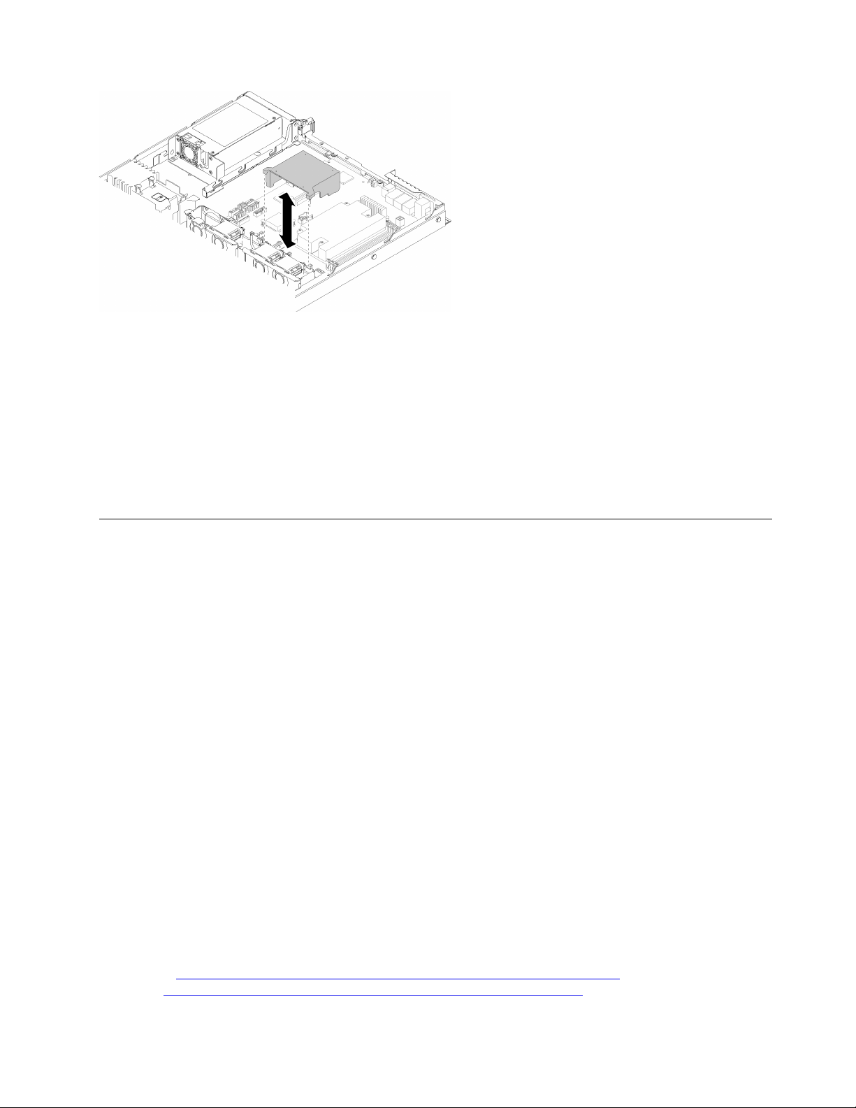
Figure 43. Air baffle installation
Step 1. Align the air baffle hooks with the slots on the top of the fan cage; then, hook the air baffle onto the
slots.
After you install the air baffle, complete the following steps:
1. Install the top cover onto the server (see “Install the top cover” on page 133 for instructions).
2. Install the server into the rack if necessary.
3. Reconnect power cords and all external cables.
Backplane replacement
Use the following information to remove and install the backplane.
Remove the hot-swap drive backplane
Use this information to remove the hot-swap drive backplane.
Before you remove the hot-swap drive backplane, complete the following steps:
1. Read the following section(s) to ensure that you work safely.
• “Safety” on page iii
• “Installation Guidelines” on page 47
2. Turn off the server. Disconnect the power cords and all external cables (see “Power off the server” on
page 10).
3. If server is installed in a rack, remove the server from the rack.
4. Remove the top cover (see “Remove the top cover” on page 132).
5. Disconnect the cables from the backplane.
6. Pull all the drives and fillers slightly out to disengage them from the backplane.
Note: Depending on the configuration, the following illustration might differ slightly from your backplane.
To remove the hot-swap drive backplane, complete the following steps:
Watch the procedure. A video of the process is available:
• Youtube:
• Youku: http://i.youku.com/i/UMjk0OTEwMDExMg==?spm=a2h1n.8251843.0.0
https://www.youtube.com/channel/UCjqE4XzuvdHpVM9lXt41M8g/playlists
Chapter 3. Hardware replacement procedures 53
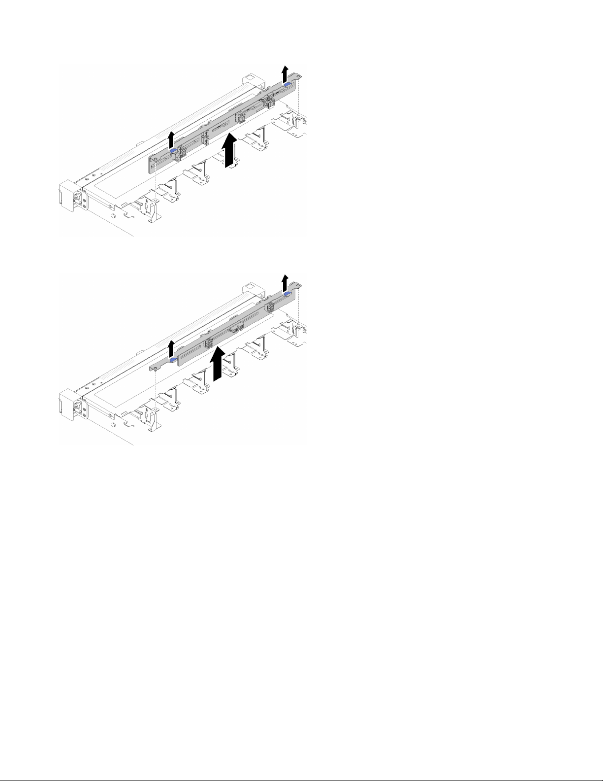
Figure 44. 2.5-inch hot-swap drive backplane removal
Figure 45. 3.5-inch hot-swap drive backplane removal
Step 1. Grasp the backplane and carefully lift it out of the chassis.
If you are instructed to return the defective component, please package the part to prevent any shipping
damage. Reuse the packaging the new part arrived in and follow all packaging instructions.
Install the hot-swap drive backplane
Use this information to install the hot-swap drive backplane.
Before you install the 3.5-inch hot-swap drive backplane, complete the following steps:
1. Read the following section(s) to ensure that you work safely.
• “Safety” on page iii
• “Installation Guidelines” on page 47
Notes:
• Depending on the configuration, the following illustration might differ slightly from your backplane.
• If the 95 W processor is used, the server does not support the ten 2.5-inch hot-swap drive backplane.
54
ThinkSystem SR250 Maintenance Manual

To install the hot-swap drive backplane, complete the following steps:
Watch the procedure. A video of the process is available:
• Youtube:
https://www.youtube.com/channel/UCjqE4XzuvdHpVM9lXt41M8g/playlists
• Youku: http://i.youku.com/i/UMjk0OTEwMDExMg==?spm=a2h1n.8251843.0.0
Figure 46. 2.5-inch hot-swap drive backplane installation
Table 28. Pin in the chassis
1 Pin
Figure 47. 3.5-inch hot-swap drive backplane installation
Table 29. Pin in the chassis
1 Pin
2 Corresponding holes
2 Corresponding holes
Step 1. Align the two pins on the backplane with the corresponding holes in the chassis.
Step 2. Lower the backplane into the chassis. Ensure that the pins pass through the holes and the
backplane is fully seated in place.
After you install the hot-swap drive backplane, complete the following steps:
Chapter 3. Hardware replacement procedures 55

1. Connect the backplane cables to the backplane. See “Internal cable routing” on page 24 for more
information.
2. Reinstall all the drives and drive fillers into the drive bays (see “Install a hot-swap drive” on page 67).
3. Install the top cover onto the server (see “Install the top cover” on page 133).
4. Install the server into the rack if necessary.
5. Reconnect power cords and all external cables.
Backplate replacement
Use the following information to remove and install the backplate.
Remove the backplate
Use this information to remove the backplate.
Before you remove the backplane, complete the following steps:
1. Read the following section(s) to ensure that you work safely.
• “Safety” on page iii
• “Installation Guidelines” on page 47
2. Turn off the server. Disconnect the power cords and all external cables (see “Power off the server” on
page 10).
3. If server is installed in a rack, remove the server from the rack.
4. Remove the top cover (see “Remove the top cover” on page 132).
5. Disconnect the cables from the system board and the RAID adapter.
6. Pull all the drives and fillers slightly out to disengage them from the backplate.
Note: Depending on the configuration, the following illustration might differ slightly from your backplate.
To remove the backplate, complete the following steps:
Watch the procedure. A video of the process is available:
• Youtube:
• Youku: http://i.youku.com/i/UMjk0OTEwMDExMg==?spm=a2h1n.8251843.0.0
Figure 48. Backplate removal
https://www.youtube.com/channel/UCjqE4XzuvdHpVM9lXt41M8g/playlists
56 ThinkSystem SR250 Maintenance Manual
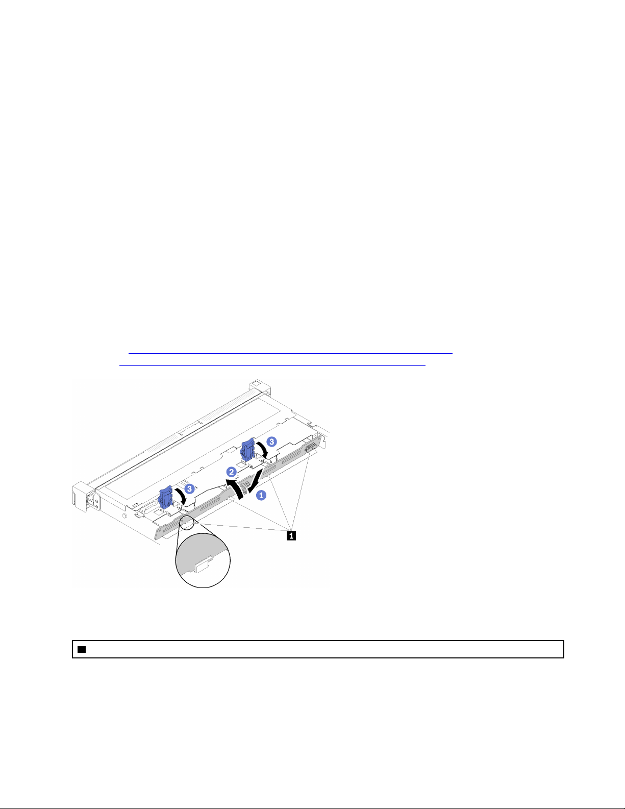
Step 1. Open the retaining clips by rotating them up.
Step 2. Rotate the backplate down toward the center of the server.
Step 3. Lift the backplate out of the server.
If you are instructed to return the defective component, please package the part to prevent any shipping
damage. Reuse the packaging the new part arrived in and follow all packaging instructions.
Install the backplate
Use this information to install the backplate.
Before you install the simple-swap drive backplate, complete the following steps:
1. Read the following section(s) to ensure that you work safely.
• “Safety” on page iii
• “Installation Guidelines” on page 47
Note: Depending on the configuration, the following illustration might differ slightly from your backplate.
To install the simple-swap drive backplate, complete the following steps:
Watch the procedure. A video of the process is available:
• Youtube:
• Youku: http://i.youku.com/i/UMjk0OTEwMDExMg==?spm=a2h1n.8251843.0.0
https://www.youtube.com/channel/UCjqE4XzuvdHpVM9lXt41M8g/playlists
Figure 49. Backplate installation
Table 30. Pin in the chassis
1 Pin
Step 1. Insert the backplate into the chassis with an angle. Make sure the pins are against the backplate on
the backside.
Step 2. Rotate the backplate up towards the front of the server.
Step 3. Close the retaining clips to secure the backplate in place.
Chapter 3. Hardware replacement procedures 57

After you install the simple-swap drive backplate, complete the following steps:
1. Connect the backplate cables to the system board and the RAID adapter (if installed). See “Internal
cable routing” on page 24 for more information.
2. Reinstall all the drives and drive fillers into the drive bays (see “Install a simple-swap drive” on page 66).
3. Install the top cover onto the server (see “Install the top cover” on page 133).
4. Install the server into the rack if necessary.
5. Reconnect power cords and all external cables.
CMOS battery replacement
Use the following information to remove and install the CMOS battery.
Remove the CMOS battery
Use this information to remove the CMOS battery.
To avoid possible danger, read and follow the following safety information.
S002
CAUTION:
The power control button on the device and the power switch on the power supply do not turn off the
electrical current that is supplied to the device. The device also might have more than one power
cord. To remove all electrical current from the device, ensure that all power cords are disconnected
from the power source.
S004
CAUTION:
When replacing the lithium battery, use only Lenovo specified part number or an equivalent type
battery recommended by the manufacturer. If your system has a module containing a lithium battery,
replace it only with the same module type made by the same manufacturer. The battery contains
lithium and can explode if not properly used, handled, or disposed of. Do not:
• Throw or immerse into water
• Heat to more than 100°C (212°F)
• Repair or disassemble
Dispose of the battery as required by local ordinances or regulations.
Before you remove the CMOS battery, complete the following steps:
1. Read the following section(s) to ensure that you work safely.
• “Safety” on page iii
58
ThinkSystem SR250 Maintenance Manual

• “Installation Guidelines” on page 47
2. If server is installed in a rack, remove the server from the rack.
3. Remove the top cover (see “Remove the top cover” on page 132).
4. Locate the CMOS battery on the system board (see “System-board connectors” on page 17).
The following notes describe information that you must consider when replacing the battery.
• Lenovo has designed this product with your safety in mind. The lithium battery must be handled correctly
to avoid possible danger. If you replace the battery, you must adhere to the following instructions.
• If you replace the original lithium battery with a heavy-metal battery or a battery with heavy-metal
components, be aware of the following environmental consideration. Batteries and accumulators that
contain heavy metals must not be disposed of with normal domestic waste. They will be taken back free
of charge by the manufacturer, distributor, or representative, to be recycled or disposed of in a proper
manner.
• After you replace the battery, you must reconfigure the solution and reset the system date and time.
To remove the CMOS battery, complete the following steps:
Watch the procedure. A video of the process is available:
• Youtube:
• Youku: http://i.youku.com/i/UMjk0OTEwMDExMg==?spm=a2h1n.8251843.0.0
https://www.youtube.com/channel/UCjqE4XzuvdHpVM9lXt41M8g/playlists
Figure 50. CMOS battery removal
Step 1. Press the battery clip in the direction as shown.
Step 2. Carefully tilt and lift CMOS battery out of the socket.
Attention: Do not use excessive force to tilt or push the battery, it might damage the socket.
If you are instructed to return the defective component, please package the part to prevent any shipping
damage. Reuse the packaging the new part arrived in and follow all packaging instructions.
Install the CMOS battery (CR2032)
Use this information to install the CMOS battery (CR2032).
To avoid possible danger, read and follow the following safety information.
S002
Chapter 3. Hardware replacement procedures 59

CAUTION:
The power control button on the device and the power switch on the power supply do not turn off the
electrical current that is supplied to the device. The device also might have more than one power
cord. To remove all electrical current from the device, ensure that all power cords are disconnected
from the power source.
S004
CAUTION:
When replacing the lithium battery, use only Lenovo specified part number or an equivalent type
battery recommended by the manufacturer. If your system has a module containing a lithium battery,
replace it only with the same module type made by the same manufacturer. The battery contains
lithium and can explode if not properly used, handled, or disposed of. Do not:
• Throw or immerse into water
• Heat to more than 100°C (212°F)
• Repair or disassemble
Dispose of the battery as required by local ordinances or regulations.
Before you install the CMOS battery, complete the following steps:
1. Read the following section(s) to ensure that you work safely.
• “Safety” on page iii
• “Installation Guidelines” on page 47
2. Locate the CMOS battery on the system board (see “System-board connectors” on page 17).
3. Touch the static-protective package that contains the component to any unpainted metal surface on the
server; then, remove it from the package and place it on a static-protective surface.
The following notes describe information that you must consider when you are replacing the CMOS battery in
the server:
• You must replace the CMOS battery with a lithium CMOS battery of the same type (CR2032).
• After you replace the CMOS battery, you must reconfigure the server and reset the system date and time.
• Dispose of the battery as required by local ordinances or regulations.
Attention:
• Do not make CMOS battery in contact with a metal surface when replace it. The contact with metal
surface, such as server side, can cause damage to the battery.
• Make sure that all server power cords are disconnected from their power sources before performing this
procedure.
To install the CMOS battery, complete the following steps:
60
ThinkSystem SR250 Maintenance Manual

Figure 51. CMOS battery installation
Watch the procedure. A video of the process is available:
• Youtube:
• Youku: http://i.youku.com/i/UMjk0OTEwMDExMg==?spm=a2h1n.8251843.0.0
Step 1. Pivot the CMOS battery to insert it into the socket, with positive (+) side faces up.
Step 2. Press the battery straight down until it clicks in place.
After you install the CMOS battery, complete the following steps:
1. Install the top cover onto the server (see “Install the top cover” on page 133).
2. Install the server into the rack if necessary.
3. Reconnect power cords and all external cables.
https://www.youtube.com/channel/UCjqE4XzuvdHpVM9lXt41M8g/playlists
DIMM replacement
Use the following information to remove and install a DIMM.
Remove a DIMM
Use this information to remove a DIMM.
Attention: Memory modules are sensitive to static discharge and require special handling. In addition to the
standard guidelines for “Handling static-sensitive devices” on page 49:
• Always wear an electrostatic-discharge strap when removing or installing memory modules. Electrostaticdischarge gloves can also be used.
• Never hold two or more memory modules together so that they touch. Do not stack memory modules
directly on top of each other during storage.
• Never touch the gold memory module connector contacts or allow these contacts to touch the outside of
the memory-module connector housing.
• Handle memory modules with care: never bend, twist, or drop a memory module.
Before you remove a DIMM, complete the following steps:
1. Read the following section(s) to ensure that you work safely.
• “Safety” on page iii
• “Installation Guidelines” on page 47
2. Turn off the server. Disconnect the power cords and all external cables (see “Power off the server” on
page 10).
3. If server is installed in a rack, remove the server from the rack.
4. Remove the top cover (see “Remove the top cover” on page 132).
Chapter 3. Hardware replacement procedures 61

5. Locate the DIMM connectors. Determine which DIMM you want to remove from the server.
Figure 52. DIMM connectors
6. When removing DIMM 4, remove the air baffle to provide more space for the DIMM removal (see
“Remove the air baffle” on page 51).
To remove a DIMM, complete the following steps:
Watch the procedure. A video of the process is available:
• Youtube:
https://www.youtube.com/channel/UCjqE4XzuvdHpVM9lXt41M8g/playlists
• Youku: http://i.youku.com/i/UMjk0OTEwMDExMg==?spm=a2h1n.8251843.0.0
Figure 53. DIMM removal
Note: To avoid breaking the retaining clips or damaging the DIMM connectors, handle the clips gently.
Step 1. Carefully open the retaining clips on each end of the DIMM connector.
62
ThinkSystem SR250 Maintenance Manual

Step 2. Make sure that both retaining clips are in the fully-open position; then, pull the DIMM out of the
connector.
If you are instructed to return the defective component, please package the part to prevent any shipping
damage. Reuse the packaging the new part arrived in and follow all packaging instructions.
Install a DIMM
Use this information to install a DIMM.
Before you install a DIMM, complete the following steps:
1. Read the following section(s) to ensure that you work safely.
• “Safety” on page iii
• “Installation Guidelines” on page 47
2. Turn off the server. Disconnect the power cords and all external cables (see “Power off the server” on
page 10).
3. Touch the static-protective package that contains the component to any unpainted metal surface on the
server; then, remove it from the package and place it on a static-protective surface.
The following illustration shows the system-board components, including DIMM connectors.
Figure 54. DIMM connectors
The following table show the sequence of DIMM installation
Chapter 3. Hardware replacement procedures 63

Table 31. DIMM installation sequence
Total DIMM
installed
1
2
3
4
DIMM 1 DIMM 2 DIMM 3 DIMM 4
√
√ √
√ √ √
√ √ √ √
To install a DIMM, complete the following steps:
Attention: Memory modules are sensitive to static discharge and require special handling. In addition to the
standard guidelines for “Handling static-sensitive devices” on page 49:
• Always wear an electrostatic-discharge strap when removing or installing memory modules. Electrostaticdischarge gloves can also be used.
• Never hold two or more memory modules together so that they touch. Do not stack memory modules
directly on top of each other during storage.
• Never touch the gold memory module connector contacts or allow these contacts to touch the outside of
the memory-module connector housing.
• Handle memory modules with care: never bend, twist, or drop a memory module.
Watch the procedure. A video of the process is available:
• Youtube:
https://www.youtube.com/channel/UCjqE4XzuvdHpVM9lXt41M8g/playlists
• Youku: http://i.youku.com/i/UMjk0OTEwMDExMg==?spm=a2h1n.8251843.0.0
Figure 55. DIMM installation
Step 1. Make sure the retaining clips are in the fully-open position; then, align the keys on the DIMM with
the connector.
Step 2. Firmly press both ends of the DIMM straight down into the connector until the retaining clips snap
into the locked position.
Step 3. If you are installing additional DIMMs, do so now.
After you install the DIMM, complete the following steps:
1. Reinstall the air baffle if it is removed (see “Install the air baffle” on page 52).
64
ThinkSystem SR250 Maintenance Manual

2. Install the top cover onto the server (see “Install the top cover” on page 133).
3. Install the server into the rack if necessary.
4. Reconnect power cords and all external cables.
Drive replacement
Use the following information to remove and install drives.
Remove a simple-swap drive
Use this information to remove a simple-swap drive.
Before you remove a simple-swap drive, complete the following steps:
1. Read the following section(s) to ensure that you work safely.
• “Safety” on page iii
• “Installation Guidelines” on page 47
2. Turn off the server. Disconnect the power cords and all external cables (see “Power off the server” on
page 10).
Attention:
• For proper system cooling, do not operate the server for more than 2 minutes without either a drive or a
filler panel installed in each bay.
• Before you make changes to drives and drive related components, back up all important data that is
stored on drives.
• Before you remove any component of a RAID array, back up all RAID configuration information.
To remove a simple-swap drive, complete the following steps:
Watch the procedure. A video of the process is available:
• Youtube:
• Youku: http://i.youku.com/i/UMjk0OTEwMDExMg==?spm=a2h1n.8251843.0.0
Figure 56. Simple-swap drive removal
Step 1. Use a flat-blade screwdriver to rotate the drive lock clockwise.
Step 2. Make sure the drive handle is released after unlocking.
Step 3. Grab the handle to pull out the drive out of the drive bay.
https://www.youtube.com/channel/UCjqE4XzuvdHpVM9lXt41M8g/playlists
Chapter 3. Hardware replacement procedures 65

If you are instructed to return the defective component, please package the part to prevent any shipping
damage. Reuse the packaging the new part arrived in and follow all packaging instructions.
Install a simple-swap drive
Use this information to install a simple-swap drive.
Before you install a simple-swap drive:
1. Read the following section(s) to ensure that you work safely.
• “Safety” on page iii
• “Installation Guidelines” on page 47
2. Touch the static-protective package that contains the drive to any unpainted metal surface on the
server; then, remove the drive from the package and place it on a static-protective surface.
Note: When the eighth SATA drive is installed, the M.2 drive is disabled.
To install a simple-swap drive, complete the following steps:
Watch the procedure. A video of the process is available:
• Youtube:
• Youku: http://i.youku.com/i/UMjk0OTEwMDExMg==?spm=a2h1n.8251843.0.0
https://www.youtube.com/channel/UCjqE4XzuvdHpVM9lXt41M8g/playlists
Figure 57. Simple-swap drive installation
Step 1. Slide the drive into the drive bay. Make sure the drive handle is in the open position.
Step 2. Lock the drive into place by rotating the drive handle inward until it clicks.
After you install all simple-swap drives, complete the following steps:
1. If you are instructed to return the defective component, please package the part to prevent any shipping
damage. Reuse the packaging the new part arrived in and follow all packaging instructions.
2. Reconnect power cords and all external cables.
Remove a hot-swap drive
Use this information to remove a hot-swap drive.
Before you remove a hot-swap drive, complete the following steps:
1. Read the following section(s) to ensure that you work safely.
• “Safety” on page iii
• “Installation Guidelines” on page 47
66
ThinkSystem SR250 Maintenance Manual
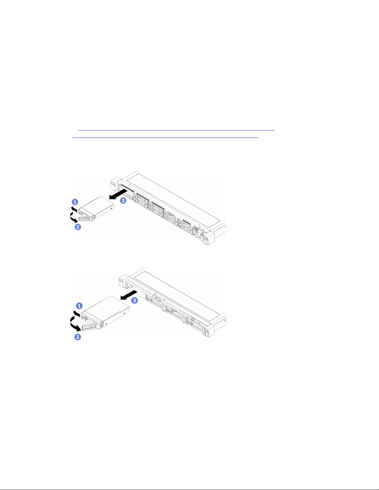
Attention:
• For proper system cooling, do not operate the server for more than 2 minutes without either a disk drive or
a filler panel installed in each bay.
• Before you make changes to disk drives and drive related components, back up all important data that is
stored on drives.
• Before you remove any component of a RAID array, back up all RAID configuration information.
To remove a hot-swap drive, complete the following steps:
Watch the procedure. A video of the process is available:
• Youtube:
https://www.youtube.com/channel/UCjqE4XzuvdHpVM9lXt41M8g/playlists
• Youku: http://i.youku.com/i/UMjk0OTEwMDExMg==?spm=a2h1n.8251843.0.0
Step 1. Slide the release latch to open the drive tray handle.
Step 2. Grasp the handle and slide the drive out of the drive bay.
Figure 58. 2.5-inch hot-swap drive removal
Figure 59. 3.5-inch hot-swap drive removal
If you are instructed to return the defective component, please package the part to prevent any shipping
damage. Reuse the packaging the new part arrived in and follow all packaging instructions.
Install a hot-swap drive
Use this information to install a hot-swap drive.
Before you install a hot-swap drive:
1. Read the following section(s) to ensure that you work safely.
• “Safety” on page iii
Chapter 3. Hardware replacement procedures 67
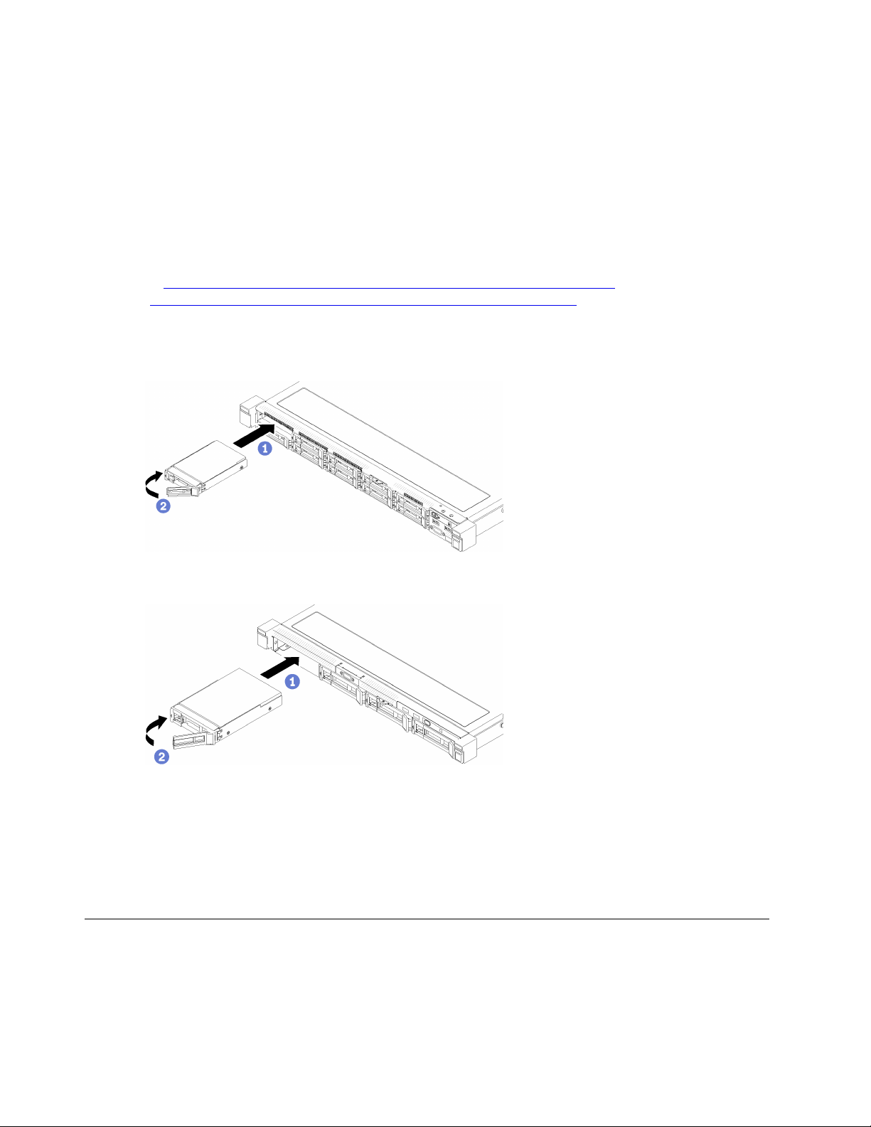
• “Installation Guidelines” on page 47
2. Remove the filler panel from the drive bay. Keep the filler panel in a safe place.
3. Touch the static-protective package that contains the drive to any unpainted metal surface on the
server; then, remove the drive from the package and place it on a static-protective surface.
Note: When the eighth SATA drive is installed, the M.2 drive is disabled.
To install a hot-swap drive, complete the following steps:
Watch the procedure. A video of the process is available:
• Youtube:
• Youku: http://i.youku.com/i/UMjk0OTEwMDExMg==?spm=a2h1n.8251843.0.0
Step 1. Slide the drive into the drive bay. Make sure the drive handle is in the open position.
Step 2. Close the drive tray handle to lock the drive in place.
https://www.youtube.com/channel/UCjqE4XzuvdHpVM9lXt41M8g/playlists
Figure 60. 2.5-inch hot-swap drive installation
Figure 61. 3.5-inch hot-swap drive installation
After you install all hot-swap drives, complete the following steps:
1. If you are instructed to return the defective component, please package the part to prevent any shipping
damage. Reuse the packaging the new part arrived in and follow all packaging instructions.
2. Reconnect power cords and all external cables.
Fan replacement
Use the following information to remove and install the fan.
Remove a fan
Use this information to remove a fan.
68
ThinkSystem SR250 Maintenance Manual

To avoid possible danger, read and follow the following safety information.
S002
CAUTION:
The power control button on the device and the power switch on the power supply do not turn off the
electrical current that is supplied to the device. The device also might have more than one power
cord. To remove all electrical current from the device, ensure that all power cords are disconnected
from the power source.
S009
CAUTION:
To avoid personal injury, disconnect the fan cables before removing the fan from the device.
Before you remove a fan, complete the following steps:
1. Read the following section(s) to ensure that you work safely.
• “Safety” on page iii
• “Installation Guidelines” on page 47
2. Turn off the server. Disconnect the power cords and all external cables (see “Power off the server” on
page 10).
3. If server is installed in a rack, remove the server from the rack.
4. Remove the top cover (see “Remove the top cover” on page 132).
5. Remove the air baffle if you are removing fan 1 and fan 2 (see “Remove the air baffle” on page 51).
To remove a fan, complete the following steps:
Watch the procedure. A video of the process is available:
• Youtube:
https://www.youtube.com/channel/UCjqE4XzuvdHpVM9lXt41M8g/playlists
• Youku: http://i.youku.com/i/UMjk0OTEwMDExMg==?spm=a2h1n.8251843.0.0
Chapter 3. Hardware replacement procedures 69

Figure 62. Fan removal
Step 1. Press and hold the fan cable latch.
Step 2. Disconnect the cable from the connector.
Step 3. Lift the fan out from the fan cage.
If you are instructed to return the defective component, please package the part to prevent any shipping
damage. Reuse the packaging the new part arrived in and follow all packaging instructions.
Install a fan
Use this information to install a fan.
To avoid possible danger, read and follow the following safety information.
S002
CAUTION:
The power control button on the device and the power switch on the power supply do not turn off the
electrical current that is supplied to the device. The device also might have more than one power
cord. To remove all electrical current from the device, ensure that all power cords are disconnected
from the power source.
S009
CAUTION:
To avoid personal injury, disconnect the fan cables before removing the fan from the device.
70
ThinkSystem SR250 Maintenance Manual

Before you install a fan, complete the following steps:
1. Read the following section(s) to ensure that you work safely.
• “Safety” on page iii
• “Installation Guidelines” on page 47
To install a fan, complete the following steps:
Watch the procedure. A video of the process is available:
• Youtube:
https://www.youtube.com/channel/UCjqE4XzuvdHpVM9lXt41M8g/playlists
• Youku: http://i.youku.com/i/UMjk0OTEwMDExMg==?spm=a2h1n.8251843.0.0
Figure 63. Fan installation
Table 32. Fan installation
1 Cable slot
2 Fan cable
Step 1. Align the fan with the slot in the fan cage; then, place the fan into the slot. Make sure the fan cable
goes in the cable slot, under the round pin as shown.
Step 2. Connect the fan cable to the connector by pressing it down until it clicks.
Chapter 3. Hardware replacement procedures 71

Figure 64. Fan power cable routing
Note: Each fan has a corresponding cable connector on system board. Make sure you connect the
cable to the right connector (see “System-board connectors” on page 17).
After you install the fan, complete the following steps:
1. Reinstall the air baffle if it was removed (see “Install the air baffle” on page 52).
2. Install the top cover onto the server (see “Install the top cover” on page 133).
3. Install the server into the rack if necessary.
4. Reconnect power cords and all external cables.
Flash power module replacement
Use the following information to remove and install the flash power module
Remove the flash power module
Use this information to remove the flash power module.
To avoid possible danger, read and follow the following safety information.
S002
72 ThinkSystem SR250 Maintenance Manual

CAUTION:
The power control button on the device and the power switch on the power supply do not turn off the
electrical current that is supplied to the device. The device also might have more than one power
cord. To remove all electrical current from the device, ensure that all power cords are disconnected
from the power source.
S004
CAUTION:
When replacing the lithium battery, use only Lenovo specified part number or an equivalent type
battery recommended by the manufacturer. If your system has a module containing a lithium battery,
replace it only with the same module type made by the same manufacturer. The battery contains
lithium and can explode if not properly used, handled, or disposed of. Do not:
• Throw or immerse into water
• Heat to more than 100°C (212°F)
• Repair or disassemble
Dispose of the battery as required by local ordinances or regulations.
Before you remove the flash power module, complete the following steps:
1. Read the following section(s) to ensure that you work safely.
• “Safety” on page iii
• “Installation Guidelines” on page 47
2. Turn off the server. Disconnect the power cords and all external cables (see “Power off the server” on
page 10).
3. If server is installed in a rack, remove the server from the rack.
4. Remove the top cover (see “Remove the top cover” on page 132).
5. Remove the RAID adapter (see “Remove the RAID adapter” on page 114).
6. Disconnect the flash power module cable.
To remove the flash power module, complete the following steps:
Watch the procedure. A video of the process is available:
• Youtube:
https://www.youtube.com/channel/UCjqE4XzuvdHpVM9lXt41M8g/playlists
• Youku: http://i.youku.com/i/UMjk0OTEwMDExMg==?spm=a2h1n.8251843.0.0
Chapter 3. Hardware replacement procedures 73

Figure 65. Flash power module removal
Step 1. Use your finger to lift the flash power module slightly.
Step 2. Slide the flash power module out of the server.
If you are instructed to return the defective component, please package the part to prevent any shipping
damage. Reuse the packaging the new part arrived in and follow all packaging instructions.
Install the flash power module
Use this information to install the flash power module.
To avoid possible danger, read and follow the following safety information.
S002
CAUTION:
The power control button on the device and the power switch on the power supply do not turn off the
electrical current that is supplied to the device. The device also might have more than one power
cord. To remove all electrical current from the device, ensure that all power cords are disconnected
from the power source.
S004
CAUTION:
When replacing the lithium battery, use only Lenovo specified part number or an equivalent type
battery recommended by the manufacturer. If your system has a module containing a lithium battery,
replace it only with the same module type made by the same manufacturer. The battery contains
lithium and can explode if not properly used, handled, or disposed of. Do not:
• Throw or immerse into water
74
ThinkSystem SR250 Maintenance Manual

• Heat to more than 100°C (212°F)
• Repair or disassemble
Dispose of the battery as required by local ordinances or regulations.
Before you install the flash power module, complete the following steps:
1. Read the following section(s) to ensure that you work safely.
• “Safety” on page iii
• “Installation Guidelines” on page 47
To install the flash power module, complete the following steps:
Watch the procedure. A video of the process is available:
• Youtube:
• Youku: http://i.youku.com/i/UMjk0OTEwMDExMg==?spm=a2h1n.8251843.0.0
https://www.youtube.com/channel/UCjqE4XzuvdHpVM9lXt41M8g/playlists
Figure 66. Flash power module installation
Step 1. Insert the end of the flash power module into its carrier.
Step 2. Rotate the flash power module down into the carrier until the tab clicks in place to secure it.
After you install the flash power module, complete the following steps:
1. Connect the required cable and make sure that all cables are correctly routed.
2. Install the top cover onto the server (see “Install the top cover” on page 133).
3. Install the server into the rack if necessary.
4. Reconnect power cords and all external cables.
Front operator panel replacement
Use this procedure to remove or install the front operator panel.
Remove the front operator panel (2.5-inch HDD model)
Use this information to remove the front operator panel (2.5-inch HDD model).
Before you remove the front operator panel (2.5-inch HDD model), complete the following steps:
Chapter 3. Hardware replacement procedures 75

1. Read the following section(s) to ensure that you work safely.
• “Safety” on page iii
• “Installation Guidelines” on page 47
2. Turn off the server. Disconnect the power cords and all external cables (see “Power off the server” on
page 10).
3. If server is installed in a rack, remove the server from the rack.
4. Remove the top cover (see “Remove the top cover” on page 132).
To remove the front operator panel (2.5-inch HDD model), complete the following steps:
Watch the procedure. A video of the process is available:
• Youtube:
https://www.youtube.com/channel/UCjqE4XzuvdHpVM9lXt41M8g/playlists
• Youku: http://i.youku.com/i/UMjk0OTEwMDExMg==?spm=a2h1n.8251843.0.0
Step 1. Disconnect the front operator panel cables from the system board.
Figure 67. Front operator panel (2.5-inch HDD model) cables removal
Step 2. Remove two screws that secure the front operator panel.
76
ThinkSystem SR250 Maintenance Manual
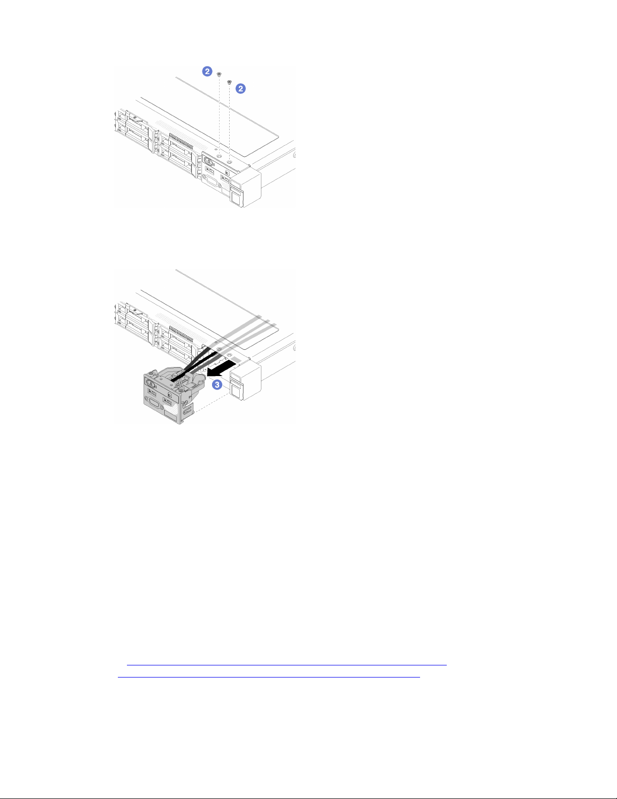
Figure 68. Screws removal
Step 3. Slide the front operator panel out of the server.
Figure 69. Front operator panel removal
If you are instructed to return the defective component, please package the part to prevent any shipping
damage. Reuse the packaging the new part arrived in and follow all packaging instructions.
Install the front operator panel (2.5-inch HDD model)
Use this information to install the front operator panel (2.5-inch HDD model).
Before you install the front operator panel (2.5-inch HDD model), complete the following steps:
1. Read the following section(s) to ensure that you work safely.
• “Safety” on page iii
• “Installation Guidelines” on page 47
To install the front operator panel (2.5-inch HDD model), complete the following steps:
Watch the procedure. A video of the process is available:
• Youtube:
https://www.youtube.com/channel/UCjqE4XzuvdHpVM9lXt41M8g/playlists
• Youku: http://i.youku.com/i/UMjk0OTEwMDExMg==?spm=a2h1n.8251843.0.0
Step 1. Slide the front operator panel into the assembly bay.
Chapter 3. Hardware replacement procedures 77

Figure 70. Front operator panel (2.5-inch HDD model) installation
Step 2. Install the two screws to secure the front operator panel.
Figure 71. Screws installation
Step 3. Connect front operator panel cables to connectors on the system board.
Note: Make sure the front I/O cables are correctly routed as illustrated.
78
ThinkSystem SR250 Maintenance Manual

Figure 72. Front operator panel (2.5-inch HDD model) cable routing
After you install the front operator panel (2.5-inch HDD model) , complete the following steps:
1. Install the top cover onto the server (see “Install the top cover” on page 133).
2. Install the server into the rack if necessary.
3. Reconnect power cords and all external cables.
Remove the front operator panel (3.5-inch HDD model)
Use this information to remove the front operator panel (3.5-inch HDD model).
Before you remove the front operator panel, complete the following steps:
1. Read the following section(s) to ensure that you work safely.
• “Safety” on page iii
• “Installation Guidelines” on page 47
2. Turn off the server. Disconnect the power cords and all external cables (see “Power off the server” on
page 10).
3. If server is installed in a rack, remove the server from the rack.
4. Remove the top cover (see “Remove the top cover” on page 132).
To remove the front operator panel, complete the following steps:
Watch the procedure. A video of the process is available:
• Youtube:
• Youku: http://i.youku.com/i/UMjk0OTEwMDExMg==?spm=a2h1n.8251843.0.0
https://www.youtube.com/channel/UCjqE4XzuvdHpVM9lXt41M8g/playlists
Chapter 3. Hardware replacement procedures 79

Step 1. Disconnect the front operator and USB cables from the system board.
Figure 73. Front operator panel (3.5-inch HDD model) removal
Step 2. Remove the two screws that secure the front operator panel.
Figure 74. Front operator panel removal
Step 3. Pull out the front operator panel from the server.
80
ThinkSystem SR250 Maintenance Manual

Figure 75. Front operator panel removal
If you are instructed to return the defective component, please package the part to prevent any shipping
damage. Reuse the packaging the new part arrived in and follow all packaging instructions.
Install the front operator panel (3.5-inch HDD model)
Use this information to install the front operator panel (3.5-inch HDD model).
Before you install the front operator panel (3.5-inch HDD model), complete the following steps:
1. Read the following section(s) to ensure that you work safely.
• “Safety” on page iii
• “Installation Guidelines” on page 47
To install the front operator panel (3.5-inch HDD model), complete the following steps:
Watch the procedure. A video of the process is available:
• Youtube:
• Youku: http://i.youku.com/i/UMjk0OTEwMDExMg==?spm=a2h1n.8251843.0.0
Step 1. Slide the front operator panel and cables into the slot on the front server.
https://www.youtube.com/channel/UCjqE4XzuvdHpVM9lXt41M8g/playlists
Figure 76. Front operator panel (3.5-inch HDD model) installation
Step 2. Install the two screws that secure the front operator panel.
Chapter 3. Hardware replacement procedures 81

Figure 77. Front operator panel (3.5-inch HDD model) installation
Step 3. Connect the front operator and USB cables to the system board.
Figure 78. Front operator panel installation
After you install the front operator panel (3.5-inch HDD model), complete the following steps:
1. Install the top cover onto the server (see “Install the top cover” on page 133).
2. Install the server into the rack if necessary.
3. Reconnect power cords and all external cables.
82
ThinkSystem SR250 Maintenance Manual

Heat sink replacement
Follow this procedure to remove and install the heat sink.
Remove the heat sink
Use this information to remove the heat sink. This procedure must be executed by a trained technician.
Before you remove the heat sink, complete the following steps:
1. Read the following section(s) to ensure that you work safely.
• “Safety” on page iii
• “Installation Guidelines” on page 47
2. Turn off the server. Disconnect the power cords and all external cables (see “Power off the server” on
page 10).
3. If server is installed in a rack, remove the server from the rack.
4. Remove the top cover (see “Remove the top cover” on page 132).
To remove the heat sink, complete the following steps:
Watch the procedure. A video of the process is available:
• Youtube:
• Youku: http://i.youku.com/i/UMjk0OTEwMDExMg==?spm=a2h1n.8251843.0.0
https://www.youtube.com/channel/UCjqE4XzuvdHpVM9lXt41M8g/playlists
Step 1. Loosen screw 1 and 2:
a. Partially loosen screw 1.
b. Fully loosen screw 2.
c. Fully loosen screw 1.
Notes:
1. Gently remove the four screws to avoid any possible damage to the system board.
2. Always keep the four screws attached to the heat sink.
3. Do not touch the thermal grease while handling the heat sink.
Step 2. Loosen screw 3 and 4:
a. Partially loosen screw 3.
b. Fully loosen screw 4.
c. Fully loosen screw 3.
Chapter 3. Hardware replacement procedures 83

Figure 79. Heat sink removal
Step 3. Lift evenly and remove the heat sink from the server.
If you are instructed to return the defective component, please package the part to prevent any shipping
damage. Reuse the packaging the new part arrived in and follow all packaging instructions.
84
ThinkSystem SR250 Maintenance Manual

Install the heat sink
Use this information to install the heat sink. This procedure must be executed by a trained technician.
Before you install the heat sink, complete the following steps:
1. Read the following section(s) to ensure that you work safely.
• “Safety” on page iii
• “Installation Guidelines” on page 47
To install the heat sink, complete the following steps:
Step 1. Align the four screws on the heat sink with the corresponding screw holes on the system board.
Step 2. Tighten screw 1 and 2:
a. Partially tighten screw 1.
b. Fully tighten screw 2.
c. Fully tighten screw 1.
Figure 80. Heat sink installation
Step 3. Tighten screw 3 and 4:
a. Partially tighten screw 3.
b. Fully tighten screw 4.
c. Fully tighten screw 3.
Chapter 3. Hardware replacement procedures 85

After you install the heat sink, complete the following steps:
1. Install the top cover onto the server (see “Install the top cover” on page 133).
2. Install the server into the rack if necessary.
3. Reconnect power cords and all external cables.
M.2 drive replacement
Use the following information to remove and install the M.2 drive.
Remove the M.2 drive
Use this information to remove the M.2 drive.
Before you remove the M.2 drive, complete the following steps:
1. Read the following section(s) to ensure that you work safely.
• “Safety” on page iii
• “Installation Guidelines” on page 47
2. Turn off the server. Disconnect the power cords and all external cables (see “Power off the server” on
page 10).
3. If server is installed in a rack, remove the server from the rack.
4. Remove the top cover (see “Remove the top cover” on page 132).
Note: There are two dimensions of M.2 drive supported by the server: 42 mm and 80mm. Both are removed
and installed in a similar method.
86
ThinkSystem SR250 Maintenance Manual

Figure 81. M.2 drive location
Table 33. M.2 drive location
1 Screw for 80 mm M.2 drive (requires a#1 Phillips and
Hex 4.5 mm screwdriver)
2 Screw for 42 mm M.2 drive (requires a #1 Phillips and
Hex 4.5 mm screwdriver)
3 M.2 connector
To remove the M.2 drive, complete the following steps:
Watch the procedure. A video of the process is available:
• Youtube:
https://www.youtube.com/channel/UCjqE4XzuvdHpVM9lXt41M8g/playlists
• Youku: http://i.youku.com/i/UMjk0OTEwMDExMg==?spm=a2h1n.8251843.0.0
Chapter 3. Hardware replacement procedures 87
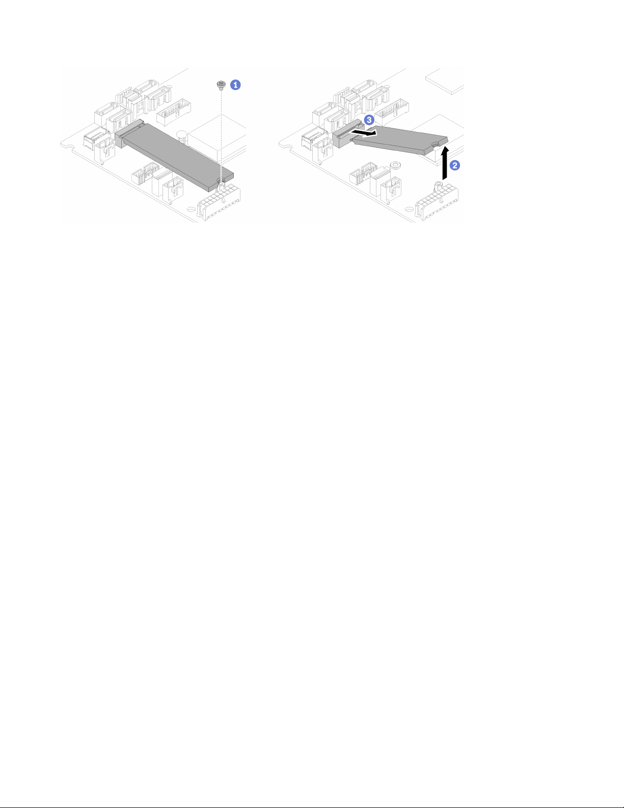
Figure 82. M.2 drive removal
Step 1. Remove the screw that secures the M.2 drive.
Step 2. Lift up the right side of the M.2 drive.
Step 3. Remove the M.2 drive from the server.
If you are instructed to return the defective component, please package the part to prevent any shipping
damage. Reuse the packaging the new part arrived in and follow all packaging instructions.
Install the M.2 drive
Use this information to install the M.2 drive in the M.2 drive.
Before you install the M.2 drive, complete the following steps:
1. Read the following section(s) to ensure that you work safely.
• “Safety” on page iii
• “Installation Guidelines” on page 47
2. Require a #1 Phillips and Hex 4.5 mm screwdriver.
Note: When the eighth SATA drive is installed, the M.2 drive is disabled.
Note: There are two dimensions of M.2 drive supported by the server: 42 mm and 80mm. Both are removed
and installed in a similar method.
88
ThinkSystem SR250 Maintenance Manual

Figure 83. M.2 drive location
Table 34. M.2 drive location
1 Screw for 80 mm M.2 drive (requires a#1 Phillips and
3 M.2 connector
Hex 4.5 mm screwdriver)
2 Screw for 42 mm M.2 drive (requires a #1 Phillips and
Hex 4.5 mm screwdriver)
Note: When you install the 80 mm or the 42 mm M.2 drive, you need to change the hex screw location
accordingly as the following illustration.
Figure 84. Hex screw location for 80 mm/42 mm M.2 drive
Chapter 3. Hardware replacement procedures 89

To install the M.2 drive, complete the following steps:
Figure 85. M.2 drive installation
Step 1. Insert the M.2 drive at an angle to the connector.
Step 2. Lower down the other side of the M.2 drive to the system board as shown.
Step 3. Fasten the screw to secure the M.2 drive.
After you install the M.2 drive, complete the following steps:
1. Install the top cover onto the server (see “Install the top cover” on page 133).
2. Install the server into the rack if necessary.
3. Reconnect power cords and all external cables.
PCIe riser assembly replacement
Use this procedure to remove or install the PCIe riser assembly.
Remove the PCIe riser assembly
Use this information to remove the PCIe riser assembly .
Before you remove the PCIe riser assembly , complete the following steps:
1. Read the following section(s) to ensure that you work safely.
• “Safety” on page iii
• “Installation Guidelines” on page 47
2. Turn off the server. Disconnect the power cords and all external cables (see “Power off the server” on
page 10).
3. If server is installed in a rack, remove the server from the rack.
4. Remove the top cover (see “Remove the top cover” on page 132).
To remove the PCIe riser assembly , complete the following steps:
90
ThinkSystem SR250 Maintenance Manual

Watch the procedure. A video of the process is available:
• Youtube:
https://www.youtube.com/channel/UCjqE4XzuvdHpVM9lXt41M8g/playlists
• Youku: http://i.youku.com/i/UMjk0OTEwMDExMg==?spm=a2h1n.8251843.0.0
Step 1. Grasp the PCIe riser assembly by its edges and carefully lift it out of the server.
Notes:
1. The following illustration might differ slightly from your hardware.
2. Carefully lift the PCIe riser assembly straight up. Avoid tilting the PCIe riser assembly at a large
angle, tilting might cause damage to the connector.
Figure 86. PCIe riser assembly removal
Step 2. Remove the two screws and carefully pull the PCIe riser card out of the riser cage.
Figure 87. PCIe riser card removal
If you are instructed to return the defective component, please package the part to prevent any shipping
damage. Reuse the packaging the new part arrived in and follow all packaging instructions.
Install the PCIe riser assembly
Use this information to install the PCIe riser assembly.
Chapter 3. Hardware replacement procedures 91

Before you install the PCIe riser assembly, complete the following steps:
1. Read the following section(s) to ensure that you work safely.
• “Safety” on page iii
• “Installation Guidelines” on page 47
2. Install the required adapters.
Notes:
1. PCIe slot 1 and slot 2 do not support ARI and SR-IOV.
2. PCIe slot 4 supports ARI and SR-IOV.
3. QLogic QL41262 PCIe 25Gb 2-Port SFP28 Ethernet Adapter does not support shared storage V3700
V2/XP and V5030 V2 configurations.
To install the PCIe riser cage, complete the following steps:
Watch the procedure. A video of the process is available:
• Youtube:
https://www.youtube.com/channel/UCjqE4XzuvdHpVM9lXt41M8g/playlists
• Youku: http://i.youku.com/i/UMjk0OTEwMDExMg==?spm=a2h1n.8251843.0.0
Step 1. Align the two screw slots on the PCIe riser card with the riser cage. Make sure two screw slot are
aligned at the same time; then, fasten the screws to secure the riser card to the riser cage.
Note: The following illustration might differ slightly from your hardware.
Figure 88. PCIe riser card installation
Step 2. Attach the label to the front side of the PCIe riser assembly.
Figure 89. PCIe riser assembly installation
Step 3. Align the two tabs on PCIe riser assembly with the slots on the rear chassis; then, insert the PCIe
riser assembly into the connector on the system board.
92
ThinkSystem SR250 Maintenance Manual
 Loading...