

Page 1

ThinkServerTD350
UserGuideandHardwareMaintenance
Manual
MachineTypes:70DG,70DH,70DJ,70DK,70DL,70DM,70DN,
and70DQ
Page 2

Note:
Beforeusingtheinformationandtheproductitsupports,besuretoreadandunderstandthefollowing:
•TheReadMeFirstthatcomeswithyourproduct
•“Safetyinformation”onpageiii
•AppendixA“Notices”onpage177
FirstEdition(September2014)
©CopyrightLenovo2014.
LIMITEDANDRESTRICTEDRIGHTSNOTICE:IfdataorsoftwareisdeliveredpursuantaGeneralServicesAdministration
“GSA”contract,use,reproduction,ordisclosureissubjecttorestrictionssetforthinContractNo.GS-35F-05925.
Page 3

Contents
Safetyinformation..........iii
Productsthatarenotassessed.........x
Safetyinspectionguide............x
Groundingrequirements............xi
Chapter1.Generalinformation.....1
Introduction.................1
Serverdocumentation.............2
Chapter2.Serversetuproadmap...5
Chapter3.Productoverview......7
Serverformfactor..............7
Serverpackage...............7
Features..................8
Specifications...............12
Software.................13
BIOSandTSMupdateutilities.......14
LenovoPartnerPackforMicrosoftSystem
CenterOperationsManagement......14
LenovoThinkServerDeploymentManager..14
LenovoThinkServerDiagnostics......15
LenovoThinkServerEnergyManager....15
LenovoThinkServerPowerPlanner.....15
LenovoThinkServerSystemManager....16
LenovoThinkServerSystemManager
Premium...............16
Locations.................16
Machinetype,model,andserialnumber
label.................16
Frontviewoftheserver.........17
Frontpanel..............20
Rearviewoftheserver.........22
Servercoverlock............24
Servercomponents...........25
Hot-swap-driveLEDs..........30
System-fanstatusLEDs.........30
PowersupplystatusLEDs........31
AnyRAIDadapter,RAIDcard,and
pass-throughboard...........32
Hot-swap-drivebackplane........37
Connectingcables...........39
Systemboardcomponents........41
Systemboardjumpers..........44
Chapter4.Turningonandturningoff
theserver...............49
Turningontheserver............49
Turningofftheserver............49
Chapter5.Configuringtheserver..51
UsingtheSetupUtilityprogram........51
StartingtheSetupUtilityprogram.....51
ViewinginformationintheSetupUtility
program...............51
SetupUtilityprograminterface......51
Settingthesystemdateandtime.....54
Usingpasswords............54
Selectingastartupdevice........55
ConfiguringtheTPMfunction.......56
SettinganEthernetconnectorforsystem
management.............56
ExitingtheSetupUtilityprogram......56
UpdatingorrecoveringtheBIOS......56
ConfiguringRAID..............58
AboutRAID..............58
ConfiguringRAIDusingtheLenovo
ThinkServerDeploymentManagerprogram.60
ConfiguringtheadvancedSATAorSAS
hardwareRAID.............60
Updatingthefirmware............61
Chapter6.Replacinghardware....63
Guidelines................63
Precautions..............63
Handlingstatic-sensitivedevices.....64
Systemreliabilityguidelines........65
Workinginsidetheserverwiththepoweron.65
Removingtheservercover..........66
Removingandreinstallingtherackhandles...67
Removingandreinstallingthecoolingshroud..68
Removingthecoolingshroud.......69
Reinstallingthecoolingshroud......69
Removingandreinstallingthefrontbezel....70
RemovingandreinstallingthePCIecardholder..74
Installing,removing,orreplacinghardware...76
Installingorremovingamemorymodule...76
InstallingorremovingaPCIExpresscard:
Ethernetcard,RAIDcard,orothersupported
typesofPCIExpresscards........84
InstallingorremovingtheSDmodule....89
InstallingorremovingtheLenovoThinkServer
RAID110iupgradekey.........91
InstallingorremovingtheLenovoThinkServer
RAID510iupgradekey.........94
Installingorremovingtheflashmodule...97
©CopyrightLenovo2014
i
Page 4

InstallingorremovingtheThinkServerSystem
ManagerPremium...........99
InstallingorremovingtheThinkServerT rusted
PlatformModule............102
Installingorremovingtheintrusionswitch..106
Installingorreplacinganopticaldrive....109
Installingorreplacingahot-swapinternal
storagedrive.............112
Installingorreplacinganeasy-swapdrive..115
Installingorreplacinganinternaltapedrive..120
Installingorreplacingthemicroprocessor..122
Installingorreplacingahot-swapredundant
powersupply.............131
Installinga2.5-inchdriveintoa3.5-inch-drive
bay.................134
Replacingthefront-panelboard......138
ReplacingtheThinkServerRAIDSuper
CapacitorModule............140
ReplacingtheAnyRAIDadapterorthe
pass-throughboard...........143
Replacingthehot-swap-drivebackplane..148
Replacingtheeasy-swap-drivemodule...150
Replacingthesystemfan.........152
Replacingtheheatsink.........154
Replacingthecoin-cellbattery......156
Forservicetechnicianonly:replacingthe
systemboard.............158
Forservicetechnicianonly:replacingthe
powerinterfaceboard..........162
Completingthepartsreplacement.......164
Reinstallingtheservercoverandreconnecting
cables................164
Updatingtheserverconfiguration.....166
Chapter7.Troubleshootingand
diagnostics.............167
Troubleshootingprocedure..........167
ViewingthestatusanddiagnosticLEDs.....167
Viewingthesystemeventlog.........167
Basictroubleshootingtables.........168
LenovoThinkServerDeploymentManager
programproblems...........168
Opticaldriveproblems..........168
Internalstoragedriveproblems......169
Memorymoduleproblems........171
Keyboard,mouse,orUSBdeviceproblems..171
Chapter8.Gettinginformation,help,
andservice.............173
Informationresources............173
Usingthedocumentation.........173
ThinkServerWebsite..........173
LenovoSupportWebsite.........173
Helpandservice..............174
Beforeyoucall.............174
Callingforservice............174
Usingotherservices..........175
Purchasingadditionalservices......175
AppendixA.Notices.........177
Trademarks................178
Importantnotes..............178
Particulatecontamination..........178
PolyvinylChloride(PVC)cableandcordnotice..179
Recyclinginformation............179
RecyclinginformationforBrazil......179
Batteryreturnprogram..........180
RequirementsforBatteriesContaining
Perchlorate..............181
ImportantWEEEinformation.........181
RestrictionofHazardousSubstancesDirective
(RoHS)..................181
EuropeanUnionRoHS..........181
GermanOrdinanceforWorkglossstatement...181
Exportclassificationnotice..........182
Electronicemissionnotices..........182
FederalCommunicationsCommission(FCC)
Statement...............182
Eurasiancompliancemark..........184
ENERGYSTARmodelinformation.......184
Index.................185
iiThinkServerTD350UserGuideandHardwareMaintenanceManual
Page 5
Safetyinformation
Note:Beforeusingtheproduct,besuretoreadandunderstandthemultilingualsafetyinstructionsonthe
documentationDVDthatcomeswiththeproduct.
Antesdeusaroproduto,leiaeentendaasinstruçõesdesegurançamultilínguesnoDVDdedocumentação
queoacompanha.
Предидаизползватетозипродукт,задължителнопрочететеивникнетевмногоезичнитеинструкции
забезопасноствDVDдискасдокументация,койтосепредоставяспродукта.
PrijeupotrebeovogproizvodaobaveznopročitajtevišejezičnesigurnosneuputekojesenalazenaDVD-us
dokumentacijomkojidobivateuzproizvod.
PředpoužitímproduktujetřebasipřečístaporozumětbezpečnostnímpokynůmuvedenýmnadiskuDVDs
dokumentací,kterýjedodávánsproduktem.
Førdubrugerproduktet,skaldusørgeforatlæseogforstådesikkerhedsforskrifter,derfindespåflere
sprog,pådendokumentations-dvd,derfølgermedproduktet.
LuetuotteenmukanatoimitetullaDVD-tietolevylläolevatmonikielisetturvaohjeetennentämäntuotteen
käyttöä.
Avantd'utiliserleproduit,veillezàbienlireetcomprendrelesinstructionsdesécuritémultilinguesfigurant
surleDVDdedocumentationfourniavecleproduit.
Πρινχρησιμοποιήσετετοπροϊόν,βεβαιωθείτεότιέχετεδιαβάσεικαικατανοήσειτιςοδηγίεςασφάλειας,οι
οποίεςείναιδιαθέσιμεςσεδιάφορεςγλώσσεςστοDVDτεκμηρίωσηςπουσυνοδεύειτοπροϊόν.
VorVerwendungdesProduktssolltenSieunbedingtdiemehrsprachigenSicherheitsanweisungenaufder
Dokumentations-DVDlesen,dieimLieferumfangdesProduktsenthaltenist.
AtermékhasználataelőttmindenképpenolvassaelésértelmezzeatermékhezkapottdokumentációsDVD
lemezentalálható,többnyelvenelolvashatóbiztonságielőírásokat.
Primadiutilizzareilprodotto,accertarsidileggereecomprendereleinformazionisullasicurezzamultilingue
disponibilisulDVDdidocumentazionefornitoconilprodotto.
製品をご使用になる前に、製品に付属のDocumentationDVDに収録されているマルチリンガルの「安
全に正しくご使用いただくために」を読んで理解してください。
제품을사용하기전에제품과함께제공되는문서DVD의다국어안전지침을주의깊게읽어보십시오.
Voordatuhetproductgebruikt,moetuervoorzorgendatudemeertaligeveiligheidsinstructiesopde
documentatie-dvdvanhetproducthebtgelezenenbegrijpt.
©CopyrightLenovo2014
iii
Page 6

Przedskorzystaniemzproduktunależyzapoznaćsięzwielojęzycznymiinstrukcjamibezpieczeństwa
znajdującymisięnapłycieDVDzdokumentacjądostarczonąwrazzproduktem.
Antesdeutilizaroproduto,leiaatentamenteasinstruçõesdesegurançamultilinguesqueconstamno
DVDdedocumentaçãofornecidocomoproduto.
Înaintedeautilizaprodusul,asiguraţi-văcăaţicititşiînţelesinstrucţiuniledesiguranţăînmaimultelimbide
peDVD-ulcudocumentaţiecareînsoţeşteprodusul.
Førdubrukerproduktet,måduleseogforstådenflerspråkligesikkerhetsinformasjonenpåDVDenmed
dokumentasjonsomfølgermedproduktet.
Преждечемиспользоватьэтотпродукт,внимательноознакомьтесьсинструкциямипотехнике
безопасностинаразныхязыках,которыеможнонайтинаDVD-дискесдокументациейвкомплектес
продуктом.
在使用本产品之前,请务必先阅读和了解产品附带的文档DVD中的多语言安全说明。
Prenegotoupotrebiteproizvodobaveznopaljivoproitajteiprouiteviejezikouputstvozabezbednostna
dokumentacionomDVD-ukojistedobiliuzproizvod.
PredpouvanmproduktusipretajteviacjazynbezpenostnpokynynadiskuDVDsdokumentcioudodanoms
produktom.
Predenzačneteuporabljatiizdelek,jepomembno,daprebereteinrazumetevečjezičnavarnostnanavodila
naDVD-juzdokumentacijo,kistegaprejeliskupajzizdelkom.
Antesdeutilizarelproducto,asegúresedeleerycomprenderlasinstruccionesdeseguridadmultilingüesdel
DVDdedocumentaciónqueseproporcionaconelproducto.
Varnogamedattläsasäkerhetsinstruktionernapådokumentations-DVD-skivansomföljermedprodukten
innandubörjaranvändaprodukten.
使用本產品之前,請務必閱讀並瞭解產品隨附的文件DVD上的多國語言版本安全資訊。
Buürünükullanmadanönce,ürünlebirliktegönderilenbelgeDVD'siüzerindekiçokdiliçerengüvenlik
yönergeleriniokuyupanladýðýnýzdaneminolun.
Передвикористаннямцьогопродуктууважноознайомтесязінструкціямизтехнікибезпекинарізних
мовах,щоможназнайтинаDVD-дискуздокументацієювкомплектізпродуктом.
Important:Fortranslatedversionsofthecautionordangerstatement,refertotheSafety,Warranty,and
SupportInformationdocument.
Ensurethatyoureadandunderstandallcautionanddangerstatementsinthisdocumentbeforeyouperform
theprocedures.Readandunderstandanyadditionalsafetyinformationthatisincludedwiththeserveror
optionaldevicebeforeyouinstall,remove,orreplacethedevice.
ivThinkServerTD350UserGuideandHardwareMaintenanceManual
Page 7
Statement1
DANGER
Electricalcurrentfrompower,telephone,andcommunicationcablesishazardous.
Toavoidashockhazard:
•Donotconnectordisconnectanycablesorperforminstallation,maintenance,orreconfigurationofthis
productduringanelectricalstorm.
•Connectallpowercordstoaproperlywiredandgroundedelectricaloutlet.
•Ensurethatallpowercordconnectorsaresecurelyandcompletelypluggedintoreceptacles.
•Connecttoproperlywiredoutletsanyequipmentthatwillbeattachedtothisproduct.
•Whenpossible,useonehandonlytoconnectordisconnectsignalcables.
•Neverturnonanyequipmentwhenthereisevidenceoffire,water ,orstructuraldamage.
•Disconnecttheattachedpowercords,telecommunicationssystems,networks,andmodemsbeforeyou
openthedevicecovers,unlessinstructedotherwiseintheinstallationandconfigurationprocedures.
•Connectanddisconnectcablesasdescribedinthefollowingtablewheninstalling,moving,oropening
coversonthisproductorattacheddevices.
Toconnect:Todisconnect:
1.T urneverythingOFF.
2.First,attachallcablestodevices.
3.Attachsignalcablestoconnectors.
4.Attachpowercordstooutlets.
5.T urndevicesON.
1.T urneverythingOFF.
2.First,removepowercordsfromoutlets.
3.Removesignalcablesfromconnectors.
4.Removeallcablesfromdevices.
Statement2
DANGER
Dangerofexplosionifbatteryisincorrectlyreplaced.
Whenreplacingthelithiumcoincellbattery,useonlythesameoranequivalenttypethatis
recommendedbythemanufacturer .Thebatterycontainslithiumandcanexplodeifnotproperly
used,handled,ordisposedof.
Donot:
•Throworimmerseintowater
•Heattomorethan100°C(212°F)
•Repairordisassemble
Disposeofthebatteryasrequiredbylocalordinancesorregulations.
©CopyrightLenovo2014
v
Page 8
Statement3
CAUTION:
Whenlaserproducts(suchasCD-ROMs,DVDdrives,fiberopticdevices,ortransmitters)are
installed,notethefollowing:
•Donotremovethecovers.Removingthecoversofthelaserproductcouldresultinexposureto
hazardouslaserradiation.Therearenoserviceablepartsinsidethedevice.
•Useofcontrolsoradjustmentsorperformanceofproceduresotherthanthosespecifiedherein
mightresultinhazardousradiationexposure.
DANGER
SomelaserproductscontainanembeddedClass3AorClass3Blaserdiode.Notethefollowing:
Laserradiationwhenopen.Donotstareintothebeam,donotviewdirectlywithoptical
instruments,andavoiddirectexposuretothebeam.
Statement4
≥18kg(39.7lb)≥32kg(70.5lb)≥55kg(121.2lb)
<32kg(70.5lb)<55kg(121.2lb)<100kg(220.5lb)
CAUTION:
Usesafepracticeswhenlifting.
Statement5
CAUTION:
Thepowercontrolbuttononthedeviceandthepowerswitchonthepowersupplydonotturnoff
theelectricalcurrentsuppliedtothedevice.Thedevicealsomighthavemorethanonepower
cord.Toremoveallelectricalcurrentfromthedevice,ensurethatallpowercordsaredisconnected
fromthepowersource.
viThinkServerTD350UserGuideandHardwareMaintenanceManual
Page 9
Statement6
CAUTION:
Ifyouinstallastrain-reliefbracketoptionovertheendofthepowercordthatisconnectedtothe
device,youmustconnecttheotherendofthepowercordtoapowersourcethatiseasilyaccessible
incaseitneedstobedisconnected.
Statement7
CAUTION:
Ifthedevicehasdoors,ensurethatyouremoveorsecurethedoorsbeforemovingorliftingthe
devicetoprotectagainstpersonalinjury.Thedoorswillnotsupporttheweightofthedevice.
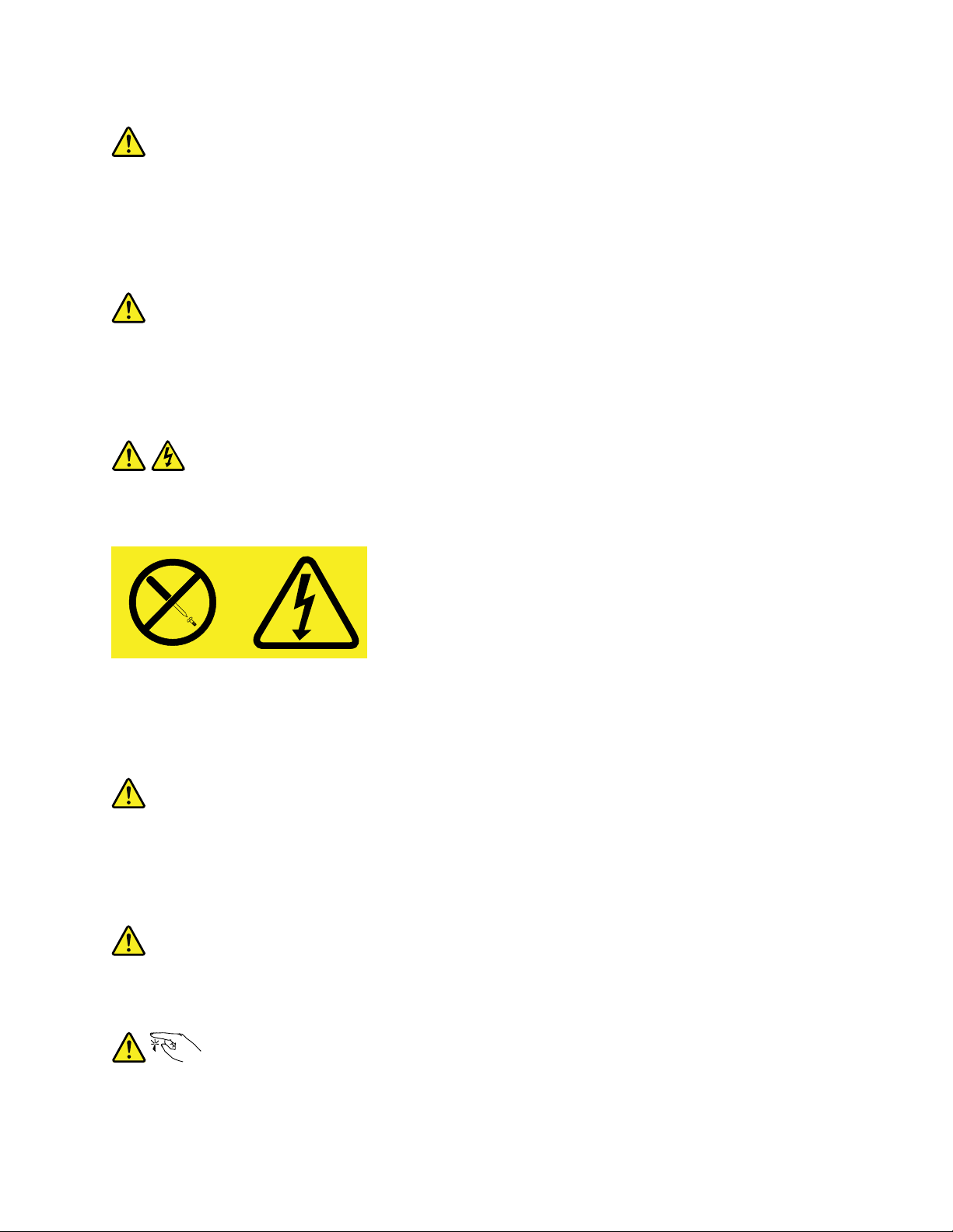
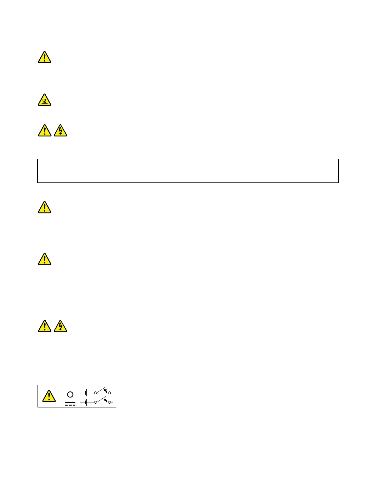
Statement8
CAUTION:
Neverremovethecoveronapowersupplyoranypartthathasthefollowinglabelattached.
Hazardousvoltage,current,andenergylevelsarepresentinsideanycomponentthathasthislabel
attached.Therearenoserviceablepartsinsidethesecomponents.Ifyoususpectaproblemwith
oneoftheseparts,contactaservicetechnician.
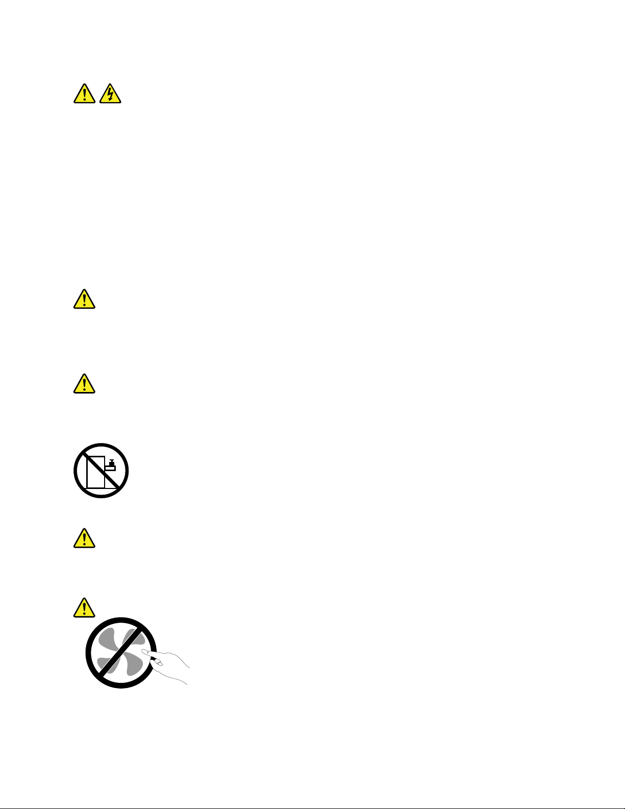
Statement9
CAUTION:
Disconnectthehot-swapfancablesbeforeremovingthefanfromthedevicetoprotectagainst
personalinjury.
Statement10
CAUTION:
Thefollowinglabelindicatesasharp-edgehazard.
©CopyrightLenovo2014
vii
Page 10
Statement11
CAUTION:
Thefollowinglabelindicatesapotentialheathazard.
Statement12
DANGER
Overloadingabranchcircuitisapotentialfirehazardandashockhazardundercertainconditions.To
avoidthesehazards,ensurethatyoursystemelectricalrequirementsdonotexceedbranchcurrentratings
attheinstallationsite.
Statement13
CAUTION:
Ensurethattherackissecuredproperlytoavoidtippingwhentheserverunitisextendedontherails.
Statement14
CAUTION:
SomeaccessoryoroptionboardoutputsexceedClass2orlimitedpowersourcelimits.You
mustinstalltheappropriateinterconnectingcablinginaccordancewithyourlocalelectricalcode
requirements.
Statement15
CAUTION:
Thepower-controlbuttononthedevicemayputthedeviceinstandbymodeinsteadofturningoff
thedevice.Inaddition,thedevicemighthavemultipleconnectionstodcpower.T oremoveall
electricalcurrentfromthedevice,ensurethatallconnectionstodcpoweraredisconnectedat
thedcpowerinputterminals.
viiiThinkServerTD350UserGuideandHardwareMaintenanceManual
Page 11
Statement16
CAUTION:
Toreducetheriskofelectricshockorenergyhazards:
•Thisequipmentmustbeinstalledbytrainedservicepersonnelinarestricted-accesslocation,as
definedbyyourlocalelectricalcodeandthelatesteditionofIEC60950.
•Thebranchcircuitovercurrentprotectionmustberatedinaccordancewithlocalelectricalcode
requirements.
•Use1.3mm
2
or16AmericanWireGauge(AWG)copperconductoronly,notexceeding3meters
inlength.
•Torquethewiring-terminalscrewsto1.4newton-metersor12inch-pounds.
•Provideareadilyavailable,approvedandrateddisconnectdeviceinthefieldwiring.
Statement17
CAUTION:
ThisproductcontainsaClass1Mlaser.Donotviewdirectlywithopticalinstruments.
Statement18
CAUTION:
Donotplaceanyobjectontopofrack-mountedproducts.
Statement19
CAUTION:
Hazardousmovingparts.Keepfingersandotherbodypartsaway.
©CopyrightLenovo2014
ix
Page 12

Statement20
CAUTION:
Alithiumionbatteryisprovided.T oavoidpossibleexplosion,donotburnthebattery.Replacethe
batteryonlywiththeLenovo-approvedpart.Recycleordiscardthebatteryasinstructedbylocal
regulations.
Productsthatarenotassessed
Typicalproductsthatarenotassessedincludebutnotlimitedtothefollowing:
•ServerandIT-rackcomponents(forexample,uninterruptiblepowersuppliesandcurrentdistribution
systems)
•DevicesinITrooms(forexample,bulkstorageunitsandnetworkproducts)
•Industriallow-voltageswitchgear
Safetyinspectionguide
Thepurposeofthisinspectionguideistoassistyouinidentifyingpotentiallyunsafeconditions.Aseach
machinewasdesignedandbuilt,requiredsafetyitemswereinstalledtoprotectusersandservicetechnicians
frominjury.Thisguideaddressesonlythoseitems.Youshouldusegoodjudgmenttoidentifypotentialsafety
hazardsduetoattachmentofnon-ThinkServerfeaturesoroptionsnotcoveredbythisinspectionguide.
Ifanyunsafeconditionsarepresent,youmustdeterminehowserioustheapparenthazardcouldbeand
whetheryoucancontinuewithoutfirstcorrectingtheproblem.
Considertheseconditionsandthesafetyhazardstheypresent:
•Electricalhazards,especiallyprimarypower(primaryvoltageontheframecancauseseriousorfatal
electricalshock)
•Explosivehazards,suchasadamagedCathodeRayTube(CRT)monitororabulgingcapacitor
•Mechanicalhazards,suchaslooseormissinghardware
Todeterminewhetherthereareanypotentiallyunsafeconditions,usethefollowingchecklistatthebeginning
ofeveryservicetask.Beginthecheckswiththepoweroff,andthepowercordsdisconnected.
Checklist:
1.Checkexteriorcoversfordamage(loose,broken,orsharpedges).
2.Powerofftheserver.Disconnectthepowercords.
3.Checkthepowercordfor:
a.Athird-wiregroundconnectoringoodcondition.Useametertomeasurethird-wireground
continuityfor0.1ohmorlessbetweentheexternalgroundpinandtheframeground.
b.Thepowercordshouldbetheauthorizedtypespecifiedforyourserver.Goto:
http://www.lenovo.com/serviceparts-lookup
c.Insulationmustnotbefrayedorworn.
4.Checkforcrackedorbulgingbatteries.
5.Removethecover.
6.Checkforanyobviousnon-ThinkServeralterations.Usegoodjudgmentastothesafetyofany
non-ThinkServeralterations.
xThinkServerTD350UserGuideandHardwareMaintenanceManual
Page 13

7.Checkinsidetheunitforanyobviousunsafeconditions,suchasmetalfilings,contamination,wateror
otherliquids,orsignsoffireorsmokedamage.
8.Checkforworn,frayed,orpinchedcables.
9.Checkthatthepower-supplycoverfasteners(screwsorrivets)havenotbeenremovedortamperedwith.
Groundingrequirements
Electricalgroundingoftheserverisrequiredforoperatorsafetyandcorrectsystemfunction.Proper
groundingoftheelectricaloutletcanbeverifiedbyacertifiedelectrician.
©CopyrightLenovo2014
xi
Page 14

xiiThinkServerTD350UserGuideandHardwareMaintenanceManual
Page 15

Chapter1.Generalinformation
Thischapterprovidessomegeneralinformationaboutyourproduct.
Thischaptercontainsthefollowingitems:
•“Introduction”onpage1
•“Serverdocumentation”onpage2
Introduction
ThisuserguideforyourLenovo
specifications,componentlocations,configurationinstructions,hardwarereplacementprocedures,and
basictroubleshootinganddiagnostics.
YourservercomeswithadocumentationDVDthatcontainsvariousserverdocumentstohelpyouuse
andmaintaintheserver.
TheLenovoLimitedWarranty(LLW)containsthewarrantytermsthatapplytotheproductyoupurchasedfrom
Lenovo.ReadtheLLWonthedocumentationDVDthatcomeswithyourserver.Aprintablegenericversion
ofthelatestLLWalsoisavailableinmorethan30languagesathttp://www.lenovo.com/warranty/llw_02.If
youcannotobtaintheLLWthroughthedocumentationDVDorLenovoWebsite,contactyourlocalLenovo
officeorresellertoobtainaprintedversionoftheLLW,freeofcharge.
®
ThinkServer
®
productcontainsinformationabouttheserverfeatures,
Forwarrantyservice,consulttheworldwideLenovoSupporttelephonelist.Telephonenumbersaresubject
tochangewithoutnotice.Themostup-to-datetelephonelistforLenovoSupportisalwaysavailableonthe
Websiteathttp://www.lenovo.com/support/phone.Ifthetelephonenumberforyourcountryorregionisnot
listed,contactyourLenovoresellerorLenovomarketingrepresentative.
Toobtainthemostup-to-dateinformationabouttheserver,goto:
http://www.lenovo.com/thinkserver
LenovomaintainspagesontheWorldWideWebwhereyoucangetthelatesttechnicalinformationand
downloaddocumentationordevicedriversandupdates.ToaccesstheLenovoSupportWebsite,goto:
http://www.lenovo.com/support
©CopyrightLenovo2014
1
Page 16

Recordinformationaboutyourserverinthefollowingtable.Youwillneedtheinformationifyoueverneed
tohaveyourserverserviced.
Forwheretofindtheproductinformationlabelonthechassis,see“Machinetype,model,andserialnumber
label”onpage16
.
Productname
Machinetypeandmodel(MT-M)
Serialnumber(S/N)
Dateofpurchase
______________________________________________
______________________________________________
______________________________________________
______________________________________________
YoucanregisteryourserverwithLenovobyfollowingtheinstructionsat:
http://www.lenovo.com/register
Whenyouregisteryourserver,informationisenteredintoadatabase,whichenablesLenovotocontact
youincaseofarecallorothersevereproblem.AfteryouregisteryourserverwithLenovo,youwillreceive
quickerservicewhenyoucallLenovoforhelp.Inaddition,somelocationsofferextendedprivilegesand
servicestoregisteredusers.
Serverdocumentation
Thistopicprovidesgeneraldescriptionsofthevariousdocumentationforyourserverandinstructionson
howtoobtainallthedocumentation.
Printeddocument
Thefollowingdocumentsareprintedoutandcontainedinyourserverpackage.
•ReadMeFirst
Thisisamultilingualdocumentyoushouldreadfirst.Thisdocumentprovidesinstructionsonhowto
accessthecompletesafety,warranty,andsupportinformationonthedocumentationDVDthatcomes
withyourserver.Thisdocumentalsoprovidesinstructionsonhowtofindthemostup-to-dateinformation
ontheLenovoSupportWebsite.
•RackInstallationInstructions(availableonsomemodels)
Thisdocumentprovidesinstructionsonhowtoinstallyourserverintoastandardrackcabinetbyusing
therailkitshippedwiththeserver.Therailkitisavailableonsomemodels.
Dependingonthemodel,aprintedEnglishversionofthisdocumentmightbeincludedinyourserver
package.PDFversionsofotherlanguagesareprovidedonthedocumentationDVDthatcomeswith
theserver.
2ThinkServerTD350UserGuideandHardwareMaintenanceManual
Page 17

DocumentationDVD
ThedocumentationDVD,whichcomeswithyourserver,containsvariousdocumentsforyourserverin
PortableDocumentFormat(PDF).Toviewthedocumentation,havetheAdobeReaderprograminstalled.Y ou
candownloadthedesiredlanguageversionofthelatestAdobeReaderprogramfromtheAdobeWebsiteat:
http://www.adobe.com
TostartthedocumentationDVD,inserttheDVDintotheopticaldrive.TheDVDisAutoPlayenabledand
startsautomaticallyinmostMicrosoft
®
Linux
operatingsystem,openthelaunch.htmfilelocatedintherootdirectoryoftheDVD.
®
Windows
®
environments.IftheDVDfailstostartorifyouareusinga
Note:LenovomaintainspagesontheWorldWideWebwhereyoucangetthelatesttechnicalinformation
anddownloaddocumentationordevicedriversandupdates.Someinformationinthedocumentsonthe
documentationDVDmightchangewithoutnoticeafterthefirstreleaseoftheDVD.Y oucanalwaysobtainall
themostup-to-datedocumentationforyourserverfromtheLenovoWebsiteat:
http://www.lenovo.com/UserManuals
ThefollowingdocumentsareonthedocumentationDVDthatcomeswithyourserver:
•Safety,Warranty,andSupportInformation
Thisisamultilingualdocumentthatincludesallthesafetystatementsforyourproductinmorethan30
languages.Besuretoreadandunderstandallthesafetystatementsbeforeusingtheproduct.This
documentalsoincludestheLenovowarrantystatement,CustomerReplaceableUnits(CRUs)information,
andinformationabouthowtocontacttheLenovoCustomerSupportCenter.
•LenovoLicenseAgreement
ThisdocumentincludesthetermsandconditionsoftheLenovoLicenseAgreement.
•UserGuideandHardwareMaintenanceManual
Thisdocumentprovidesdetailedinformationtohelpyougetfamiliarwithyourserverandhelpyouuse,
configure,andmaintainyourserver.
•RackInstallationInstructions(availableonsomemodels)
Thisdocumentprovidesinstructionsonhowtoinstallyourserverintoastandardrackcabinetbyusing
therailkitshippedwiththeserver.Therailkitisavailableonsomemodels.
•ThinkServerSystemManagerUserGuide
Thisdocumentprovidesinformationaboutserverremotemanagement.ThisdocumentisinEnglishonly.
YoumightfindthisdocumentonthedocumentationDVDthatcomeswithyourserver.Ifnot,downloadit
fromtheLenovoWebsiteat:
http://www.lenovo.com/UserManuals
Note:Toobtainadvancedremotemanagementfunctions,installaThinkServerSystemManagerPremium
(TSMPremium)ontheTSMPremiumconnectoronthesystemboard.See“Installingorremovingthe
ThinkServerSystemManagerPremium”onpage99
.
•MegaRAIDSASSoftwareUserGuide
ThisdocumentprovidesinformationaboutRedundantArrayofIndependentDisks(RAID)andhowto
usetheutilityprogramstoconfigure,monitor,andmaintainyourserverRAIDandrelateddevices.This
documentisinEnglishonly.
•Otherdocuments
YoumightfindotherdocumentsfortheHostBusAdapter(HBA),Ethernetcard,orotheroptionalparts
onthedocumentationDVD.
Chapter1.Generalinformation3
Page 18

4ThinkServerTD350UserGuideandHardwareMaintenanceManual
Page 19

Chapter2.Serversetuproadmap
Thischapterprovidesageneralroadmaptoguideyouthroughsettingupyourserver.
Theserversetupprocedurevariesdependingontheconfigurationoftheserverwhenitwasdelivered.In
somecases,theserverisfullyconfigured.Connecttheservertothenetworkandanacpowersource,and
thenyoucanturnontheserver.Inothercases,theserverneedstohavehardwaredevicesinstalled,requires
hardwareandfirmwareconfiguration,andrequiresanoperatingsystemtobeinstalled.
Thegeneralprocedureforsettingupyourserveris:
1.Unpacktheserverpackage.See“Serverpackage”onpage7.
2.Installanyrequiredhardwareorserveroption.SeetherelatedtopicinChapter6“Replacinghardware”
onpage63.
3.Dependingonthemodel,installtheserverintoastandardrackcabinetbyusingtherailkitshipped
withtheserver.SeeRackInstallationInstructionsthatcomeswithyourserver.TherailkitandRack
InstallationInstructionsareavailableonsomemodels.
4.ConnecttheEthernetcableandpowercordstotheserver.See“Rearviewoftheserver”onpage
tolocatetheconnectors.
22
5.Turnontheservertoverifyoperation.See“Turningontheserver”onpage49.
6.ReviewtheUnifiedExtensibleFirmwareInterface(UEFI)BasicInputOutputSystem(BIOS)settingsand
customizeasneeded.See“UsingtheSetupUtilityprogram”onpage51
7.ConfigureRAIDandinstalltheoperatingsystemandbasicdrivers.See“LenovoThinkServer
DeploymentManager”onpage14
8.Installanyadditionaldriversrequiredforaddedfeatures.Refertotheinstructionsthatcomewith
thehardwareoption.
9.ConfigureEthernetsettingsintheoperatingsystembyreferringtotheoperatingsystemhelp.This
stepisnotrequirediftheoperatingsystemwasinstalledusingtheLenovoThinkServerDeployment
Managerprogram.
10.Checkforfirmwareanddriverupdates.See“Updatingthefirmware”onpage61.
11.Installmanagementapplicationsandanyotherapplications.Refertothedocumentationthatcomes
withtheapplicationsthatyouwanttoinstall.
and“ConfiguringRAID”onpage58.
.
©CopyrightLenovo2014
5
Page 20

6ThinkServerTD350UserGuideandHardwareMaintenanceManual
Page 21

Chapter3.Productoverview
Thischaptercontainsthefollowingitems:
•“Serverformfactor”onpage7
•“Serverpackage”onpage7
•“Features”onpage8
•“Specifications”onpage12
•“Software”onpage13
•“Locations”onpage16
Serverformfactor
Theserverisdesignedtosupportbothtowerandrackformfactors.Mostservercomponentsarethesame
betweenthetwoformfactors.Thedifferenceisthatthetower-form-factorservermodelscomewithfoot
stands,andtherack-form-factorservermodelscomewithrackhandles.Mostillustrationsshowninthis
documentationarebasedonthetower-form-factorservermodel.
Serverpackage
Note:Dependingonthemodel,yourservermightlookdifferentfromthefollowingillustration.
©CopyrightLenovo2014
7
Page 22

Figure1.Serverpackage
1Cablemanagementbar(availableonsomemodels)
2Railkit(availableonsomemodels)
3Keyboard
4Server
5Materialbox,includingpowercords,printeddocumentation,andadocumentationDVD
Features
Thistopicprovidesgeneralinformationabouttheserverfeaturesforvariousmodels.Dependingonyour
specificmodel,somefeaturesmightvaryornotbeavailable.Forinformationaboutyourspecificmodel,use
theSetupUtilityprogram.See“ViewinginformationintheSetupUtilityprogram”onpage51.Youalsocan
refertotheProductSpecificationsReferencedocumentforThinkServerproductsat:
http://www.lenovo.com/psref/
Microprocessor
OneortwoIntel
®
®
Xeon
microprocessors(internalcachesizevariesbymodel)
ForalistofThinkServermicroprocessoroptions,goto:
http://lenovoquickpick.com/usa/home/thinkserver/rack-and-tower-server
Memory
Yourserverhas16memoryslots.Formoreinformation,see“Systemboardcomponents”onpage41and
“Memorymoduleinstallationrules”onpage76
.
8ThinkServerTD350UserGuideandHardwareMaintenanceManual
Page 23

Powersupply
Yourservercomeswithoneofthefollowingpowersupplyconfigurations:
•Oneortwohot-swap550-wattpowersupplies(universalinputandcompliantwith80PLUSPlatinum)
•Oneortwohot-swap750-wattpowersupplies(universalinputandcompliantwith80PLUSPlatinum)
•Oneortwohot-swap750-wattpowersupplies(universalinputandcompliantwith80PLUSTitanium)
•Oneortwohot-swap1100-wattpowersupplies(universalinputandcompliantwith80PLUSPlatinum)
Airflowandcooling
•Oneortwoheatsinksformicroprocessorcooling
•Foursystemfans
Internaldrives
Internaldrivesaredevicesthatyourserverusestoreadandstoredata.Theinternaldrivessupported
byyourservervarybymodel.
•Internalstoragedrive
Dependingonthemodel,yourserversupportsdifferentstoragedrives,suchasharddiskdrivesor
solid-statedrives.Theterm“2.5-inchhot-swapdrives”or“2.5-inchdrives”hereinafterreferstoallthe
supportedtypesof2.5-inchdrives,includingthesolid-statedrives.
Drivebay
Eight2.5-inchdrivebays
Eight2.5-inchdrivebays
Sixteen2.5-inchdrivebays
Five3.5-inchdrivebays
Five3.5-inchdrivebays
Fifteen3.5-inchdrivebays
Supporteddrivetype
Hot-swap,SATA
Harddiskdrive
Hot-swap,SATAorSAS
Harddiskdriveorsolid-statedrive
Hot-swap,SATAorSAS
Harddiskdriveorsolid-statedrive
Easy-swap,SATA
Harddiskdrive
Hot-swap,SATA
Harddiskdrive
Hot-swap,SATAorSAS
Harddiskdriveorsolid-statedrive
Note:Forservermodelswithfifteen3.5-inch-drivebays,youcaninstall2.5-inchdrivesand3.5-inch
drivesintothesameserver.Formoreinformation,see“Installinga2.5-inchdriveintoa3.5-inch-drive
bay”onpage134
.
•Opticaldrive
–Uptotwo5.25-inchSATAopticaldrives
Theserverhastwoopticaldrivebays.Theloweroptical-drivebayisinstalledwitha5.25-inchSATA
opticaldrive.Theupperbayisforasecondaryopticaldrive.Someservermodelscomewitha
secondaryopticaldriveinstalledintheupperbay.
•Tapedrive
Yourserversupportsaninternaltapedrivethatenablesyoutostoredataontapemedia.Formore
information,see“Installingorreplacinganinternaltapedrive”onpage120
.
Tolocatetheinternaldrivesordrivebays,see“Frontviewoftheserver”onpage17.
Chapter3.Productoverview9
Page 24

Externaldrives
Ifyourserverhasahostbusadapter(HBA)installed,anexternalstoragedevicecanbeconnectedtostore
data.Formoreinformation,refertothedocumentationthatcomeswiththeexternalstoragedevice.
Expansionslots
TheserverhassevenexpansionslotsonthesystemboardforinstallingappropriatePeripheralComponent
InterconnectExpress(PCIe)cards.Fordetailedinformation,see“Systemboardcomponents”onpage41.
Input/Output(I/O)features
•Oneserialconnectorontherearpanel
•OneVideoGraphicsArray(VGA)DB-15connectorontherearpanel
•ThreeRJ-45Ethernetconnectorsontherearpanel
•FourUSB3.0connectorsontherearpanel
•TwoUSB2.0connectorsonthefrontpanel
Tolocatetheconnectors,refertotherelatedtopicsin“Locations”onpage16.
Videosubsystem
AnintegratedgraphicscontrollerintheThinkServerSystemManager(TSM),whichalsoisknownasthe
BaseboardManagementController(BMC)chip,isinstalledonthesystemboardtosupportaVGAconnector
ontherearpanelforconnectingvideodevices.
Ethernetconnectivity
TheservercomeswithanintegratedIntelGigabitEthernetcontrolleraswellasanEthernetphysicallayer
(PHY)oftheOpenSystemsInterconnectionmodel(OSImodel).Theyprovidetheserverwiththeabilityto
supporttwoEthernetconnectorsontherearpanelwith10megabitspersecond(Mbps),100Mbps,or1000
Mbpsnetworkconnectivity.Formoreinformation,see“Rearviewoftheserver”onpage22
.
YoucaninstallanEthernetcardtoenablemoreEthernetconnectors.However,youmustinstalladevice
drivertoenabletheoperatingsystemtorecognizetheEthernetconnectors.Thedevicedriversareavailable
fordownloadat:
http://www.lenovo.com/drivers
Reliability,availability,andserviceability
Reliability,availability,andserviceability(hereinafterreferredtoasRAS)arethreeimportantserverdesign
features.TheRASfeatureshelpyoutoensuretheintegrityofthedatastoredontheserver,theavailabilityof
theserverwhenyouneedit,andtheeasewithwhichyoucandiagnoseandcorrectproblems.
YourserverhasthefollowingRASfeatures:
10ThinkServerTD350UserGuideandHardwareMaintenanceManual
Page 25

•Securityfeatures
–Servercoverlock(see“Servercoverlock”onpage24
)
–Administratorpasswordanduserpasswordtohelpprotectunauthorizedaccesstotheserver(see
“Usingpasswords”onpage54)
–ThinkServerTrustedPlatformModule(TPM),whichisasecuritychip,tohelpenhanceserversecurity
Note:TheTPMisonlyavailableonsomemodels.
–Remotemonitoringorcontrolbyanadministratortoprovideprotectionorhelp
–Hot-swapredundantpowersuppliestohelpavoidsignificantinterruptiontotheoperationofthe
systemwhenapowersupplyfails
•Basicsystemmanagementfeatures
–Abilitytostorethepower-onself-test(POST)hardwaretestresults
–BIOSSetupUtilityprogram
TheBIOSSetupUtilityprogramhelpsyouviewtheserverinformationandconfiguretheserverinthe
pre-operatingsystemenvironment.See“UsingtheSetupUtilityprogram”onpage51.
–TSM(alsoknownasBMC),andIntelligentPlatformManagementInterface(IPMI)2.0
ThesystemboardplatformmanagementsubsystemisbasedontheintegratedThinkServerSystem
Manager(TSM)features.TheTSMisamanagementchipthatisintegratedonthesystemboardof
yourserver.WiththeTSMchip,nomatterwhatconditiontheserveroperatingsystemisinandno
matteriftheserverisonoroff,aslongastheserverisconnectedtonetworkandanacpowersource,
theinteractionwiththeTSM-controlledserverscanbeachievedthroughsystemnetwork.Theusercan
obtaintheserverhardwarehealthinformationandsystemeventlog(SEL),andisabletoconductthe
operationsincludingturningonorofftheserver,restartingtheserver,andsoon.Thispartofserver
managementisindependentoftheoperatingsystemandiscalledout-of-bandmanagement.
ThesystemboardplatformmanagementsubsystemconsistsoftheintegratedTSM,communication
buses,sensors,BIOS,andservermanagementfirmware.Itisresponsibleforerrorreporting,system
powercontrol,thermalmonitoring,systemfancontrol,andothermanagementfeatures.TheTSM
providessystemmanagementandmonitoringfeaturesbasedontheIPMI2.0specification.IPMIhelps
lowertheoverallcostsofservermanagement.YoucanfindmoreinformationaboutIPMI2.0from
theWebsiteofIntel.TheTSMalsosupportssomenon-IPMIfeatures,suchastheDynamicHost
ConfigurationProtocol(DHCP)andthePlatformEnvironmentControlInterface(PECI),toprovide
moresystemmanagementfunctions.
Youcanfindthedefaultusername,password,andotherinformationfortheTSMintheThinkServer
SystemManagerUserGuide,whichisavailablefordownloadat:
http://www.lenovo.com/UserManuals
–Hot-swapfeature
Somemodelssupporthot-swapstoragedrivesandallmodelssupporthot-swappowersuppliesand
hot-swapsystemfans.Withthehot-swapfeature,youcaninstall,remove,orreplacestoragedrives,a
failingpowersupply,orafailingsystemfanwithoutturningofftheserver.
–PrebootExecutionEnvironment(PXE)
TheIntelPXEtechnologyenablesyoutobootyourcomputers,loadanoperatingsystem,ordeploy
executableimagesfromaremoteserverbyusinganetworkinterface.Theoperationcanbedone
independentlyoflocaldatastoragedevices(suchasstoragedrives)oroperatingsystems.
–RedundantArrayofIndependentDisks(RAID)
YourserversupportsonboardSATAsoftwareRAID.YourserveralsosupportsadvancedSATA/SAS
hardwareRAIDconfigurationsifyouhavearequiredRAIDcardinstalled.Fordetailedinformation,
see“ConfiguringRAID”onpage58
.
Chapter3.Productoverview11
Page 26

–Statuslight-emittingdiodes(LEDs)anddiagnosticLEDs
ForinformationabouttheLEDsforyourserver,refertotherelatedtopicsin“Locations”onpage16.
–Softwareprograms
Forinformationaboutthesoftwareprograms,see“Software”onpage13.
–WakeonLAN
WhentheWakeonLANfeatureisenabledonacomputerthatisconnectedtoalocalareanetwork
(LAN),anetworkadministratorcanremotelyturnonorwakeupthecomputerfromamanagement
consoleusingremotenetworkmanagementsoftware.Besides,manyotherfunctions,suchasdata
transferandsoftwareupdates,canbeperformedremotelywithoutremoteattendanceandcanbedone
afternormalworkinghoursandonweekendstosavetimeandincreaseproductivity.
•Advancedsystemmanagementfeatures
TheadvancedsystemmanagementfeaturesareonlyavailablewhentheTSMdetectsthepresence
ofaThinkServerSystemManagerPremium(TSMPremium),whichalsoisknownastheintegrated
keyboard,video,andmouse(iKVM)key.TheTSMPremiumisaremotemanagementmodule.Youcan
purchaseaTSMPremiumfromLenovoandinstallitontheTSMPremiumconnector(alsoknownasiKVM
connector)onthesystemboardofyourservertoenabletheiKVMfunctionandactivatetheadvanced
systemmanagementfeatures.
Formoreinformationaboutadvancedsystemmanagement,refertotheThinkServerSystemManager
UserGuide,whichisavailablefordownloadat:
http://www.lenovo.com/UserManuals
Specifications
Thistopicliststhephysicalspecificationsforyourserver.
Dimensions
•Fortowerformfactor
Width:173mm(6.81inches)
Height:459mm(18.07inches)withfootstands
Depth:685mm(26.97inches)includingthefrontdoor
•Forrackformfactor
Width:482mm(18.98inches)withrackhandles
Height:173mm(6.81inches)
Depth:664mm(26.14inches)
Weight
Theproductweightvariesdependingondifferentsystemconfigurations.
Rangeofproductweightwithoutpackage:22kg(48.5lb)to41.5kg(91.49lb)
Rangeofproductweightwithpackage:31kg(68.34lb)to50.5kg(111.33lb)
Electricalinput
Universalinput:
•Minimum:
90Vacfor550-watt,750-watt,and1100-wattredundantpowersuppliescompliantwith80PLUS
Platinum
12ThinkServerTD350UserGuideandHardwareMaintenanceManual
Page 27

180Vacfor750-wattredundantpowersuppliescompliantwith80PLUSTitanium
•Maximum:264Vac
•Inputfrequencyrange:47to63Hz
Environment
Dependingonthehardwareconfiguration,someservermodelscomplywithASHRAEclassA4specifications.
TheotherservermodelscomplywithASHRAEclassA3specifications.
•Forservermodelsthatmeetallofthefollowingconfigurationrequirementsatthesametime:
TheseservermodelscomplywithASHRAEclassA4specifications,suchasairtemperature,altitude,
andhumidityaslisted.
Hardwareconfigurationrequirements:
Environmentinformation:
–Easy-swap-drivebaysoreight2.5-inch-drive
bays
–CPU:Lenovo-qualified;amaximumof120-W
thermaldesignpower;notlow-powertype(no
L-suffixintheCPUname)
–Donothaveinternaltapedrivesinstalled
–Twopowersuppliesinstalledforredundancy
–PCIecard:Lenovo-qualified;power
consumptionofeachcarddoesnotexceed15
W
Note:Whenthealtitudeexceeds900m(2953ft),thedefinedmaximumdry-bulbtemperaturefor
operationbecomesadependentvariable.Thistemperaturevaluedecreasesby1°C(33.8°F)with
every125m(410ft)ofaltitudeincrease.
•Fortheotherservermodels:
TheseservermodelscomplywithASHRAEclassA3specifications,suchastheairtemperature,altitude,
andhumidityinformationaslisted.
–Dry-bulbtemperature:
Operating:From5°C(41°F)to40°C(104°F)
Storage:From-40°C(-40°F)to60°C(140°F)inoriginalshippingpackage
–Altitude:From0m(0ft)to3048m(10000ft)
–Humidity:
–Dry-bulbtemperature:
Operating:From5°C(41°F)to45°C(113°F)
Storage:From-40°C(-40°F)to60°C(140°F)
inoriginalshippingpackage
–Altitude:From0m(0ft)to3048m(10000ft)
–Humidity:
Operating:From8%to90%
(non-condensing)
Storage:From8%to90%(non-condensing)
Operating:From8%to85%(non-condensing)
Storage:From8%to90%(non-condensing)
Note:Whenthealtitudeexceeds900m(2953ft),thedefinedmaximumdry-bulbtemperaturefor
operationbecomesadependentvariable.Thistemperaturevaluedecreasesby1°C(33.8°F)with
every175m(574ft)ofaltitudeincrease.
Software
Thistopicprovidesinformationaboutthesoftwareprogramsthatyoucanusetosetup,use,andmaintain
theserver.
Chapter3.Productoverview13
Page 28

Todownloadthesoftwareprograms,gototheLenovoSupportWebsiteathttp://www.lenovo.com/support
andfollowtheinstructionsontheWebpage.
BIOSandTSMupdateutilities
TheBIOSandTSM(alsoknownasBMC)firmwarekeepsupdatingaftertheshipmentoftheserver.Lenovo
maintainspagesontheSupportWebsiteandprovidestheBIOSandTSMupdateutilitieswithinstructions
fordownloadtohelpyouupdatetheBIOSandTSMfirmwareifneeded.Formoreinformation,see“Updating
orrecoveringtheBIOS”onpage56
and“Updatingthefirmware”onpage61.
LenovoPartnerPackforMicrosoftSystemCenterOperations Management
TheLenovoPartnerPackforMicrosoftSystemCenterOperationsManagementprogramautomatically
detectsthemanagedserversofyourThinkServerserverandprovidesdetailedsysteminformationaboutthe
managedservers.Thesysteminformationincludescomponentinventory,componentstatus,andsensor
status.Theprogramalsoenablesuserstoperformmanagementtasks,suchasrestartingorturningoffyour
ThinkServerserver,andaccessingtheTSMinterface.
Fordetailedinformationaboutusingtheprogram,refertothehelpsystemoftheprogram.
LenovoThinkServerDeploymentManager
TheLenovoThinkServerDeploymentManagerprogram(hereinafterreferredtoasDeploymentManager)
simplifiestheprocessofconfiguringRAID,configuringBIOSsettings,andupdatingthefirmware.The
programworksinconjunctionwithyourWindowsorLinuxoperatingsysteminstallationdisctoautomatethe
processofinstallingtheoperatingsystemandassociateddevicedrivers.Theprogramispartoftheserver
firmware.Thehelpsystemfortheprogramcanbeaccesseddirectlyfromtheprograminterface.
DeploymentManagerhasthefollowingfeatures:
•Easy-to-use,language-selectableinterface
•Integratedhelpsystem
•Automatichardwaredetection
•Selectablepartitionsizeandfilesystemtype
•Abilitytoinstalltheoperatingsystemanddevicedriversinanunattendedmodetosavetime
•AbilitytocreateareusableresponsefilethatcanbeusedwithsimilarlyconfiguredLenovoserversto
makefutureinstallationsevenfaster
•ContainsRAIDconfigurationutility
•Providesdevicedriversbasedontheservermodelanddetecteddevices
•SupportsBIOSsettingsconfiguration
•Supportsfirmwareandapplicationsupdate
TouseDeploymentManager,dothefollowing:
1.Launchtheprogramthroughoneofthefollowingmethods:
•Turnontheserver.PressF10assoonasyouseethelogoscreen.Then,waitforseveralseconds.
DeploymentManageropens.
•StarttheSetupUtilityprogram.SelectBootManager➙LaunchTDM.DeploymentManageropens.
2.Readandacceptthelicenseagreement.
14ThinkServerTD350UserGuideandHardwareMaintenanceManual
Page 29

3.Selectthelanguageinwhichyouwanttoviewtheprogram.Then,followtheinstructionsonthe
screentousetheprogram.
BeforeinstallingaWindowsoraLinuxoperatingsystemusingDeploymentManager,itisrecommended
thatyoudothefollowing:
1.Downloadthelatestdevicedriverbundlefileforyourserver.Tofindanddownloadthebundlefile,goto
http://www.lenovo.com/driversandfollowtheinstructionsontheWebpage.
2.LaunchDeploymentManagerandclickPlatformUpdateontheleftpane.
3.SelectApplicationandthenclickNext.
4.ClickBrowsetoselectthecorrespondingbundlefileandthenclickOK.Theversioninformationis
displayed.
5.ClickFlashtoapplythebundlefileandupdatethecurrentdevicedrivers.
Note:IfyouwanttoinstallaVMwarehypervisororanyothersupportedoperatingsystemusingDeployment
Manager,thedevicedriverbundlefileisnotneeded.
TodownloadthelatestDeploymentManager,gotohttp://www.lenovo.com/driversandfollowthe
instructionsontheWebpage.
LenovoThinkServerDiagnostics
TheLenovoThinkServerDiagnosticsprogramenablesyoutodiagnoseserverproblems,performsome
diagnostictests,andcollectsysteminformation.Examplesofthesysteminformationincludebasic
operating-systeminformation,hardwareinformation,SEL,RAIDlog,andsoon.Dependingonthemodel,
yourservermightcomewithoneofthefollowingdiagnosticprograms:
•LenovoThinkServerDiagnosticsLinuxEdition
•LenovoThinkServerDiagnosticsStandaloneEdition
•LenovoThinkServerDiagnosticsWindowsEdition
FordetailedinformationaboutusingtheLenovoThinkServerDiagnosticsprogram,refertothehelpsystem
fortheprogram.
LenovoThinkServerEnergyManager
TheLenovoThinkServerEnergyManagerprogramisaprogramfordatacenterenergymanagement.It
monitorsthepowerandtemperatureattheserverlevelandthegrouplevel.Byanalyzingthemonitored
powerandtemperatureinformation,EnergyManagerhelpsyouimprovethebusinesscontinuityandenergy
efficiency.
FordetailedinformationaboutusingtheEnergyManagerprogram,refertothehelpsystemfortheprogram.
LenovoThinkServerPowerPlanner
TheLenovoThinkServerPowerPlannerprogramprovidesinformationaboutdatamaintenance,power
consumption,electriccurrentcalculations,andsoon.Theprogramhelpsyouconvenientlymanageservers
anddevicestoincreasethedeploymentefficiencysignificantly.
FordetailedinformationaboutusingtheLenovoThinkServerPowerPlannerprogram,refertothehelp
systemoftheprogram.
Chapter3.Productoverview15
Page 30

LenovoThinkServerSystemManager
TheLenovoThinkServerSystemManager(TSM)isamanagementsolutionthatprovidescomprehensive
andsecuremanagementfeatures.Thesefeaturesenableyoutomanageyourserversremotelyusing
aone-to-oneorone-to-manymethod.
TheTSMprovidesaone-to-oneweb-basedconsole.Theweb-basedconsoleisdevelopedinHTML5and
structuredinthewaythatmakesplatformmanagementintuitiveandefficient.TheTSMalsoprovidesa
securecommand-lineinterfaceforimprovedefficiencyandfunctionality.
FordetailedinformationaboutusingtheLenovoThinkServerSystemManagerprogram,refertothehelp
systemoftheprogram.
LenovoThinkServerSystemManagerPremium
LenovoThinkServerSystemManagerPremiumprovidesyouasolutionthatenablesyoutoreceiveallthe
benefitsandfeaturesprovidedbyboththeLenovoThinkServerSystemManagerprogramandtheLenovo
ThinkServerEnergyManagerprogram.ItalsoenablesyoutocontroltheserverremotelyusingLenovovirtual
keyboard,video,andmouse.
Fordetailedinformationaboutusingtheprogram,refertothehelpsystemoftheprogram.
Locations
Thistopicprovidesinformationtohelpyoulocateyourservercomponents.
Machinetype,model,andserialnumberlabel
WhenyoucontactLenovoforhelp,themachinetype,model,andserialnumberinformationhelpssupport
technicianstoidentifyyourserverandprovidefasterservice.
16ThinkServerTD350UserGuideandHardwareMaintenanceManual
Page 31

Thefollowingillustrationisanexampleofthemachinetype,model,andserialnumberlabelontheserver.
Note:Dependingonthemodeltype,yourservermightlookdifferentfromthisillustration.
Figure2.Machinetype,model,andserialnumberlabel
Frontviewoftheserver
Thefrontviewoftheservervariesbymodel.Y ourservermightlookdifferentfromtheillustrationsinthistopic.
Chapter3.Productoverview17
Page 32

Frontviewofservermodelswithfifteen
3.5-inch-drivebays
Figure3.Frontviewoftheserver
Frontviewofservermodelswithsixteen
2.5-inch-drivebays
1Optical-drivestatusLED2Optical-driveeject/closebutton
3Optical-drivemanual-ejecthole4Optical-drivebay1
5Optical-drivebay2
7Storage-drivebays
1Optical-drivestatusLED
6Frontpanel
8Metalprotectiveshields
Theoptical-drivestatusLEDisblinkingingreenwhentheopticaldriveisworkingorinthePOSTprocess.
2Optical-driveeject/closebutton
Pressthisbuttontoejectorclosetheopticaldrivewhentheserverpowerison.
3Optical-drivemanual-ejecthole
Insertastraightenedpaperclipintotheoptical-drivemanual-ejectholetoejectthedisctraywhenthe
eject/closebuttondoesnotwork.
4Optical-drivebay1
Yourservercomeswitheitheranopticaldriveoratapedriveinstalledinthe5.25-inchoptical-drivebay1.
5Optical-drivebay2
The5.25-inchoptical-drivebay2isforasecondaryopticaldrive.Somemodelshaveasecondaryoptical
driveinstalled.Formoreinformation,see“Installingorreplacinganopticaldrive”onpage109
18ThinkServerTD350UserGuideandHardwareMaintenanceManual
.
Page 33

6Frontpanel
Fordetailedinformationaboutthecontrol,connectors,andstatusLEDsonthefrontpanel,see“Front
panel”onpage20.
7Storage-drivebays
Thestorage-drivebaysareusedtoinstall3.5-inchor2.5-inchinternalstoragedrives.Dependingonthe
model,yourserversupportsoneofthefollowingstorage-drivebayconfigurations:
•Five3.5-inch-drivebays
•Fifteen3.5-inch-drivebays
•Eight2.5-inch-drivebays
•Sixteen2.5-inch-drivebays
Note:Forservermodelswithfifteen3.5-inch-drivebays,youcaninstall2.5-inchdrivesand3.5-inchdrives
intothesameserver.Formoreinformation,see“Installinga2.5-inchdriveintoa3.5-inch-drivebay”on
page134.
8Metalprotectiveshields
Themetalprotectiveshieldsareusedtocovervacantstorage-drivebays.
Attention:Anunoccupiedstorage-drivebaywithoutanyotherprotectionmightimpacttheEMIintegrityand
coolingoftheserver,whichmightresultinoverheatingorcomponentdamage.
Chapter3.Productoverview19
Page 34

Frontpanel
Thefollowingillustrationshowsthecontrol,connectors,andLEDsonthefrontpaneloftheserver.
Note:Dependingonthemodel,yourservermightlookdifferentfromtheillustrationinthistopic.
Figure4.Frontpanel
1PowerbuttonwithpowerstatusLED
3Storage-driveactivityLED
5SystemhealthLED6USB2.0connectors(2)
1PowerbuttonwithpowerstatusLED
2SystemIDbuttonwithIDLED
4NetworkstatusLED
Pressthepowerbuttontoturnontheserverwhenyoufinishsettinguptheserver.Holdthepowerbutton
forseveralsecondstoturnofftheserverifyoucannotturnitofffromtheoperatingsystem.SeeChapter
4“Turningonandturningofftheserver”onpage49
.ThepowerstatusLEDhelpsyoutoidentifythe
currentpowerstatus.
PowerstatusLED
OnGreen
Off
Color
Theserverison.
None
Theserverisoff.
Description
20ThinkServerTD350UserGuideandHardwareMaintenanceManual
Page 35

2SystemIDbuttonwithIDLED
WhenyoupressthesystemIDbutton,theIDLEDsonboththefrontandrearoftheserverarelit.Asa
result,youcanlocatetheserveramongotherservers.Y oualsocanturnontheIDLEDsusingaremote
managementprogramforserverpresencedetection.
IDLED
On
Off
3Storage-driveactivityLED
Color
Blue
None
Theserverisidentified.
TheIDLEDisnotinuseortheserverisnotidentified.
Description
Note:Thestorage-driveactivityLEDisonlyforservermodelswitheasy-swapstoragedrives.
Storage-driveactivityLEDColor
OnGreen
Off
4NetworkstatusLED
Thestoragedriveisactiveanddataisbeing
transferred.
NoneThestoragedriveisnotinuse.
Description
ThenetworkstatusLEDindicatetheLANstatusfortheEthernetconnectorsontherearoftheserver.
NetworkstatusLED
OnGreen
Off
Blinking
Color
TheserverisconnectedtoaLAN.
None
Green
TheserverisdisconnectedfromaLAN.
TheLANisconnectedandactive.
Description
5SystemhealthLED
ThesystemhealthLEDhelpsyoutoidentifyifthereareanysystemerrors.
•Off:Theserverisoffortheserverisonandworkingnormally.
•Blinking:TheBMCisinitiating.
•Amber:Theserverhaspotentialsystemerrors.Checktheinformationinthefollowingtableforpotential
systemerrorsandcorrespondingsolutions.
Potentialsystemerror(systemhealthLED:amber)Solution
Thetemperatureoftheserverreachedthenon-critical
temperaturethreshold.
Thevoltageoftheserverreachedthenon-criticalvoltage
threshold.
Afanisrunningatlowspeed.
Thepowersupplyhasacriticalerror.
ChecktheBMCforerrorsandcheckthesystemfans.
Replacethesystemboard.
Note:ThisactionmustbeperformedonlybyLenovo
servicepersonnel.SeeChapter8“Gettinginformation,
help,andservice”onpage173
Checkthesystemfans.
ChecktheBMCfordetailedinformation.
.
Chapter3.Productoverview21
Page 36

Potentialsystemerror(systemhealthLED:amber)Solution
Apowercordhasbeendisconnectedoraredundant
powersupplyhasbeenremoved.
Thesystemisoverheated.
6USB2.0connectors(2)
1.Ensurethatthepowersuppliesareinstalledsecurely.
2.Ensurethatthepowercordsareconnectedsecurely
tothepowersupplies.
3.Installanewpowersupplytoreplacetheremoved
one.
ChecktheBMCforerrorsandthencheckthesystem
fans.
UsedtoconnectUSBdevices(USB1.0,USB1.1,andUSB2.0compatible),suchasaUSBkeyboard,
mouse,scanner,orprinter.IfyouhavemorethansixUSBdevices,youcanpurchaseaUSBhub,which
youcanusetoconnectadditionalUSBdevices.
Rearviewoftheserver
Note:Dependingonthemodel,yourservermightlookslightlydifferentfromtheillustrationinthistopic.
Figure5.Rearviewoftheserverwithtwohot-swapredundantpowersupplies
1Hot-swappowersupplies(2)
3VGADB-15connector4PCIecardslots(3)
5USB3.0connectors(4)
7EthernetRJ-45connector28EthernetRJ-45connector1
9Servercoverkey10Serialconnector
11PCIecardslots(4)
2IDLED
6EthernetRJ-45connector0
22ThinkServerTD350UserGuideandHardwareMaintenanceManual
Page 37

1Hot-swappowersupplies
Yourservermodelmighthaveoneortwohot-swappowersupplies.Eachhot-swappowersupplyhasone
powercordconnectorontherear.Oneachpowersupply,therearethreestatusLEDsnearthepowercord
connector.ForinformationaboutthestatusLEDs,see“PowersupplystatusLEDs”onpage31
2IDLED
.
WhenyoupressthesystemIDbutton,theIDLEDsonboththefrontandrearoftheserverarelit.Asa
result,youcanlocatetheserveramongotherservers.Y oualsocanturnontheIDLEDsusingaremote
managementprogramforserverpresencedetection.
IDLED
On
Off
3VGADB-15connector
Color
Blue
None
Theserverisidentified.
TheIDLEDisnotinuseortheserverisnotidentified.
Description
UsedtoattachaVGA-compatiblevideodevice,suchasaVGAmonitor.
411PCIecardslots
YourserverhassevenPCIecardslotsonthesystemboardforyoutoinstallappropriatePCIecards.For
informationaboutthePCIecardslots,see“Systemboardcomponents”onpage41.
5USB3.0connectors
UsedtoconnectUSBdevices(USB1.0,USB1.1,USB2.0,andUSB3.0compatible),suchasaUSB
keyboard,mouse,scanner,orprinter.IfyouhavemorethansixUSBdevices,youcanpurchaseaUSBhub,
whichyoucanusetoconnectadditionalUSBdevices.
Chapter3.Productoverview23
Page 38

678EthernetRJ-45connectors
UsedtoattachanEthernetcableforaLAN.EachEthernetconnectorhastwostatusLEDstohelpyou
identifytheEthernetconnectivity,activity,andconnectionspeed.
TheEthernetconnector0(callout6)markedwith“MGMT”isforsystemmanagementbydefault.Ifyou
wanttouseremotemanagementfunctions,connectanEthernetcabletotheEthernetconnector0.You
alsocansettheEthernetconnector1forsystemmanagement.See“SettinganEthernetconnector
forsystemmanagement”onpage56
Figure6.EthernetstatusLEDs
.
EthernetstatusLED
1Left:dataspeed
2Right:linkandactivity
9Servercoverkey
ColorStatus
Amber
GreenOn
None
GreenOn
None
Green
On
Off
Off
BlinkingTheLANisconnectedandactive.
Theconnectionspeedis1000Mbps.
Theconnectionspeedis100Mbps.
Theconnectionspeedis10Mbps.
TheserverisconnectedtoaLAN.
TheserverisdisconnectedfromaLAN.
Description
Usedtoopenorlocktheservercover.Savethekeyinasafeplacetoavoidloss.
10Serialconnector
Usedtoattachadevicethatusesa9-pinserialconnector.
Servercoverlock
Theservercoverlock1preventsunauthorizedaccesstotheinsideofyourserver.Youcanremovethekey
attachedontherearoftheserveranduseittoopenorlocktheservercover.
Note:Dependingonthemodel,yourservermightlookslightlydifferentfromtheillustrationinthistopic.
24ThinkServerTD350UserGuideandHardwareMaintenanceManual
Page 39

Figure7.Servercoverlock
Servercomponents
Toaccesstheinsideoftheserverandviewtheservercomponents,removetheservercover.See“Removing
theservercover”onpage66.
Thechassisconfigurationvariesbymodel.Thefollowingillustrationsshowthethreechassisconfigurations
basedonthesupportedbackplaneormodule.
•Servermodelswithone3.5-inchhot-swap-drivebackplane
•Servermodelswithone2.5-inchhot-swap-drivebackplanes
•Servermodelswithone3.5-incheasy-swap-drivemodule
Note:Dependingonthemodel,yourservermightlookdifferentfromtheillustrationsinthistopic.
Chapter3.Productoverview25
Page 40

Thefollowingillustrationshowsthecomponentsofservermodelswithone3.5-inchhot-swap-drive
backplane.
Figure8.Componentsofservermodelswithone3.5-inchhot-swap-drivebackplane
1AnyRAID-adapterairduct(availableonsome
2AnyRAIDadapter(availableonsomemodels)
models)
3AnyRAID-adaptertray
4ThinkServerRAIDSuperCapacitorModules(availableon
somemodels)
53.5-inchhot-swap-drivebackplane
7PCIecardholder8CPU1DIMMs(varybymodel)
9CPU2DIMMs(varybymodel)10Heatsinks(varybymodel)
11Intrusionswitch(availableonsomemodels)12Coin-cellbattery
13CPU1DIMMs(varybymodel)14PCIecardholder
15Coolingshroud
6Systemfans
26ThinkServerTD350UserGuideandHardwareMaintenanceManual
Page 41

Thefollowingillustrationshowsthecomponentsofservermodelswithone2.5-inchhot-swap-drive
backplane.
Figure9.Componentsofservermodelswithone2.5-inchhot-swap-drivebackplane
1Pass-throughboard(availableonsomemodels)
32.5-inchhot-swap-drivebackplane
5PCIecardholder6CPU1DIMMs(varybymodel)
7CPU2DIMMs(varybymodel)8Heatsinks(varybymodel)
9Intrusionswitch(availableonsomemodels)10Coin-cellbattery
11CPU1DIMMs(varybymodel)12PCIecardholder
13Coolingshroud
2AnyRAID-adaptertray
4Systemfans
Chapter3.Productoverview27
Page 42

Thefollowingillustrationshowsthecomponentsofservermodelswithoneeasy-swap-drivemodule.
Figure10.Componentsofservermodelswithoneeasy-swap-drivemodule
1Easy-swap-drivemodule
3PCIecardholder4CPU1DIMMs(varybymodel)
5CPU2DIMMs(varybymodel)6Heatsinks(varybymodel)
7Intrusionswitch(availableonsomemodels)8Coin-cellbattery
9CPU1DIMMs(varybymodel)10PCIecardholder
11Coolingshroud
2Systemfans
CRUidentification
CRUsarepartsthatcanbeupgradedorreplacedbythecustomer.IfaCRUisdeterminedtobedefective
duringthewarrantyperiod,areplacementCRUwillbeprovidedtothecustomer.Customersareresponsible
forinstallingtheself-serviceCRUsforthisproduct.Customersalsocaninstalloptional-serviceCRUs,which
mightrequiresometechnicalskillsortools,orrequestthatatechnicianinstalltheoptional-serviceCRU
underthetermsoftheapplicablewarrantyservicetypeforyourcountryorregion.
Non-CRUsmustbereplacedonlybytrainedservicetechnicians.
ThefollowingtableliststhemajorFRUsinyourserverandtheCRUidentificationinformation.Foracomplete
listingofFRUinformation,suchasFRUpartnumbersandsupportedservermodels,goto:
http:/www.lenovo.com/serviceparts-lookup
28ThinkServerTD350UserGuideandHardwareMaintenanceManual
Page 43

Notes:
•BeforeservicingaLenovoproduct,ensurethatyoureadandunderstand“Safetyinformation”onpageiii
•UseonlypartsprovidedbyLenovo.
Description
AnyRAIDadapter(availableonsomemodels)
AnyRAID-adapterairduct(availableonsome
models)
Coin-cellbattery
Coolingshroud
Easy-swapstoragedrive(availableonsome
models)
Easy-swap-drivemodule(availableonsome
models)
FrontbezelYesNo
Frontdoor(availableonsomemodels)
Front-panelboardYesNo
HeatsinkYesNo
Hot-swapstoragedrive(availableonsome
models)
Hot-swap-drivebackplane(availableonsome
models)
Hot-swappowersupplyY esNo
Internaltapedrive(availableonsomemodels)
Intrusionswitch(availableonsomemodels)
MemorymoduleYesNo
MicroprocessorNoYes
Opticaldrive(availableonsomemodels)
PCIecard(availableonsomemodels)
Powerinterfaceboard
SDmodule(availableonsomemodels)
Systemboard
Systemfan
ThinkServerRAID110ipass-throughboard
ThinkServerRAID110iupgradekey(availableon
somemodels)
ThinkServerRAID510iupgradekey(availableon
somemodels)
ThinkServerRAIDSuperCapacitorModule
(availableonsomemodels)
ThinkServerSystemManagerPremium(available
onsomemodels)
ThinkServerT rustedPlatformModule(available
onsomemodels)
Self-serviceCRUOptional-serviceCRU
NoYes
YesNo
YesNo
YesNo
YesNo
NoYes
YesNo
YesNo
NoYes
YesNo
NoYes
YesNo
YesNo
NoNo
NoYes
NoNo
YesNo
NoYes
YesNo
YesNo
YesNo
YesNo
YesNo
.
Chapter3.Productoverview29
Page 44

Hot-swap-driveLEDs
Thistopicappliesonlytoservermodelswithhot-swapinternalstoragedrives.
Eachhot-swapstoragedrivehastwoLEDsonthefront.
Figure11.Hot-swap-driveLEDs
1ActivityLED
OffOff
On,greenOff
Blinking,green
On,greenBlinkingrapidly(aboutfourflashes
On,greenOn,amber
Blinking,green
Off
persecond),amber
Blinkingslowly(aboutoneflashper
second),amber
2StatusLED
Thedrivehasfailedorisnotpresent.
Thedriveispresentbutnotinuse.
Thedriveisactiveanddataisbeing
transferred.
TheRAIDcontrollerisidentifyingthe
drive.
TheRAIDarrayhasfailedandcannot
berecovered.Y oumustrecreatea
newarray.
Thedriveisbeingrebuilt.
Description
System-fanstatusLEDs
YourserverhasfoursystemfansandeachsystemfanhasonecorrespondingstatusLEDonthechassis.
Removetheservercovertoviewthesystem-fanstatusLEDs.
Note:Dependingonthemodel,yourservermightlookslightlydifferentfromtheillustrationinthistopic.
30ThinkServerTD350UserGuideandHardwareMaintenanceManual
Page 45

Figure12.System-fanstatusLEDs
System-fanstatusLEDColor
Off
On
PowersupplystatusLEDs
Eachhot-swappowersupplyhasthreestatusLEDs.
Description
None
Amber
Thecorrespondingsystemfanis
operatingnormally.
Thecorrespondingsystemfanis
runningatlowspeedorhasbeen
removed.ChecktheBMCforerrors
andrunthediagnosticprograms.See
“LenovoThinkServerDiagnostics”on
page15
.
Chapter3.Productoverview31
Page 46

1
2
3
Figure13.PowersupplystatusLEDs
LED
1InputstatusLED
2OutputstatusLED
Status
Off
On,green
Off
Blinking,green(aboutone
flasheverytwoseconds)
Blinking,green(abouttwo
flashespersecond)
On,green
Off
On,amber
DescriptionAction
Thepowersupplyis
disconnectedfromthe
acpowersource.
Thepowersupplyis
connectedtotheacpower
source.
Theserverisofforthe
powersupplyisnotworking
normally.
Thepowersupplyisinthe
coldredundancyactive
mode.
Thepowersupplyisinthe
coldredundancysleepmode.
Theserverisonandthe
powersupplyisworking
normally.
Thepowersupplyisworking
normally.
Thepowersupplyhasfailed.
Noactionisneeded.
Noactionisneeded.
Replacethepowersupply.
See“Installingorreplacinga
hot-swapredundantpower
supply”onpage131.
Noactionisneeded.
Noactionisneeded.
Noactionisneeded.
Noactionisneeded. 3FaultLED
Replacethepowersupply.
See“Installingorreplacinga
hot-swapredundantpower
supply”onpage131
.
AnyRAIDadapter,RAIDcard,andpass-throughboard
ThistopicprovidesinformationtohelpyoulocatetheconnectorsontheAnyRAIDadapter,RAIDcard,
andpass-throughboard.
TheAnyRAIDadapterandRAIDcardprovideadvancedSATA/SAShardwareRAIDfunctions.The
pass-throughboardprovidesSATAsoftwareRAIDfunctions.YoucanpurchaseasupportedAnyRAID
adapter,RAIDcard,orpass-throughboardfromtheLenovoWebsiteat:
http://lenovoquickpick.com/usa/home/thinkserver/rack-and-tower-server
Note:TheoptionkitforAnyRAIDadapter,RAIDcard,orpass-throughboardisdesignedfordifferenttypes
ofserversandmightcontainadditionalcablesthatarenotrequiredforyourserver.
Forinformationabouttheinstallationorreplacement,refertothefollowingtopics:
•“ReplacingtheAnyRAIDadapterorthepass-throughboard”onpage143
•“InstallingorremovingaPCIExpresscard:Ethernetcard,RAIDcard,orothersupportedtypesofPCI
Expresscards”onpage84
32ThinkServerTD350UserGuideandHardwareMaintenanceManual
Page 47

YourserversupportsthefollowingAnyRAIDadapter,RAIDcard,andpass-throughboard:
AnyRAIDadapters(supportedtypevariesbyservermodel):
•LenovoThinkServerRAID510iAnyRAIDAdapter
•LenovoThinkServerRAID720iAnyRAIDAdapter
•LenovoThinkServerRAID720ixAnyRAIDAdapter
UseLenovoThinkServerRAID720ixAnyRAIDAdapterforservermodelssupportingtheinternaltapedrive.
RAIDcard:
•LenovoThinkServer9286RAIDcard
Pass-throughboard:
•LenovoThinkServerRAID110ipass-throughboard
UseLenovoThinkServerRAID110ipass-throughboardforservermodelsthatsupportonlyhot-swap
SATAstoragedrives.
Note:Dependingontheconfiguration,theAnyRAIDadapter,RAIDcard,orpass-throughboardinstalledin
yourservermightlookslightlydifferentfromtheillustrationsinthistopic.
LenovoThinkServerRAID510iAnyRAIDAdapter
Figure14.LenovoThinkServerRAID510iAnyRAIDAdapter
1PCI-E0connector
2PCI-E1connector
UsedtoconnecttotheAnyRAIDconnector1–2onthesystemboard.See“Systemboardcomponents”
onpage41.
3RAIDupgradekeyconnector
UsedtoconnectaThinkServerRAID510iupgradekey.
Chapter3.Productoverview33
Page 48

LenovoThinkServerRAID720iAnyRAIDAdapter
Figure15.LenovoThinkServerRAID720iAnyRAIDAdapter
1ThinkServerRAIDSuperCapacitorModuleconnector(availableonsomemodels)
UsedtoconnecttheThinkServerRAIDSuperCapacitorModule.See“Servercomponents”onpage25.
2PCI-E0connector
3PCI-E1connector
UsedtoconnecttotheAnyRAIDconnector1–2onthesystemboard.See“Systemboardcomponents”
onpage41
.
34ThinkServerTD350UserGuideandHardwareMaintenanceManual
Page 49

LenovoThinkServerRAID720ixAnyRAIDAdapter
Figure16.LenovoThinkServerRAID720ixAnyRAIDAdapter
1SATAconnector
Usedtoconnectthesignalcablefromtheinternaltapedrive.
2ThinkServerRAIDSuperCapacitorModuleconnector
UsedtoconnecttheThinkServerRAIDSuperCapacitorModule.See“Servercomponents”onpage25
3PCI-E0connector
4PCI-E1connector
UsedtoconnecttotheAnyRAIDconnector1–2onthesystemboard.See“Systemboardcomponents”
onpage41.
.
Chapter3.Productoverview35
Page 50

LenovoThinkServer9286RAIDcard
Figure17.LenovoThinkServer9286RAIDcard
1ThinkServerRAIDSuperCapacitorModuleconnector
UsedtoconnecttheThinkServerRAIDSuperCapacitorModule.See“Servercomponents”onpage25.
2SASconnector0–3
3SASconnector4–7
Usedtoconnectexternalstoragedevices.
LenovoThinkServerRAID110ipass-throughboard
Figure18.LenovoThinkServerRAID110ipass-throughboard
1SATAconnector0–3
2SATAconnector4–7
UsedtoconnecttotheSATAconnector0(ports0–3)andSATAconnector1(ports4–7)onthesystem
board.See“Systemboardcomponents”onpage41
.
36ThinkServerTD350UserGuideandHardwareMaintenanceManual
Page 51

Hot-swap-drivebackplane
Yourservercomeswithoneofthefollowingdrivebayandbackplaneconfigurations:
•Five3.5-inch-drivebayswithonebackplane
•Fifteen3.5-inch-drivebayswithonebackplane
•Eight2.5-inch-drivebayswithonebackplane
•Sixteen2.5-inch-drivebayswithtwobackplanes
Thefollowingillustrationshowsthelocationofthehot-swap-drivebackplane.Toaccessthebackplane,
opentheservercoverandremovetheAnyRAIDadapterorpass-throughboard.See“Removingtheserver
cover”onpage66and“ReplacingtheAnyRAIDadapterorthepass-throughboard”onpage143.
Notes:
•Dependingonthemodel,yourservermightlookdifferentfromthefollowingillustration.
•Thefollowingillustrationisbasedonservermodelsthathavefifteen3.5-inch-drivebayswithone
backplane
1.
Figure19.Backplanelocation
Chapter3.Productoverview37
Page 52

3.5-inchhot-swap-drivebackplane
Thefollowingillustrationsshowtheconnectorsona3.5-inchhot-swap-drivebackplane.
Figure20.Frontviewofthe3.5-inchhot-swap-drivebackplane
Figure21.Rearviewofthe3.5-inchhot-swap-drivebackplane
0–14Slot0–slot14
Usedtoconnect3.5-inchhot-swapdrives.
158-pinpowerconnector
Usedtoconnectapowercabletoprovidepowertothebackplane.
16AnyRAID-adapterslots
UsedtoconnectanAnyRAIDadapterorapass-throughboard.
38ThinkServerTD350UserGuideandHardwareMaintenanceManual
Page 53

2.5-inchhot-swap-drivebackplane
Thefollowingillustrationsshowtheconnectorsona2.5-inchhot-swap-drivebackplane.
Figure22.Frontviewofthe2.5-inchhot-swap-drivebackplane
Figure23.Rearviewofthe2.5-inchhot-swap-drivebackplane
0–7Slot0–slot7
Usedtoconnect2.5-inchhot-swapdrives.
810-pinpowerconnector
Usedtoconnectapowercabletoprovidepowertothebackplane.
9AnyRAID-adapterslot
UsedtoconnectanAnyRAIDadapterorapass-throughboard.
Connectingcables
Thistopicprovidesinstructionsonhowtoconnectcables:
•“Connectingthemini-SAStoPCIesignalcablefromthesystemboardtotheAnyRAIDadapter”on
page39
•“ConnectingtheSATAsignalcablefromthesystemboardtothepass-throughboard”onpage40.
•“Connectingtheeasy-swap-drivemoduletothesystemboard”onpage40
Connectingthemini-SAStoPCIesignalcablefromthesystemboardtotheAnyRAID
adapter
ThistopicappliesonlytoservermodelsthathaveanAnyRAIDadapterinstalled.
.
.
Toconnectthemini-SAStoPCIesignalcable(hereinafterreferredtoastheYcable)fromthesystem
boardtotheAnyRAIDadapter,dothefollowing:
1.UseoneYcable.Connectthedual-inconnectorsononeendoftheYcabletothePCI-E0connector
andthePCI-E1connectorontheAnyRAIDadapter.
Chapter3.Productoverview39
Page 54

2.ConnectthesingleconnectorontheotherendoftheYcabletotheAnyRAIDconnector1–2onthe
systemboard.
Tolocatetheconnectors,refertotherelatedtopicsin“Locations”onpage16.
ConnectingtheSA TAsignalcablefromthesystemboardtothepass-throughboard
Thistopicappliesonlytoservermodelsthathaveapass-throughboardinstalled.
ToconnecttheSATAsignalcablefromthesystemboardtothepass-throughboard,dothefollowing:
1.UseoneSATAsignalcable.ConnectoneendoftheSATAsignalcabletotheSATAconnector0–3and
theSATAconnector4–7onthepass-throughboard.
2.ConnecttheotherendoftheSATAsignalcabletotheSATAconnector0andtheSATAconnector1
onthesystemboard.
Tolocatetheconnectors,refertotherelatedtopicsin“Locations”onpage16.
Connectingtheeasy-swap-drivemoduletothesystemboard
Thistopicappliesonlytoservermodelsthatcomewithaneasy-swap-drivemodule.
Toconnecttheeasy-swap-drivemoduletothesystemboard,dothefollowing:
1.Connectthesignalcableoftheeasy-swap-drivemoduletotheSATAconnector0andSATAconnector1
onthesystemboard.
2.Connectthepowercableoftheeasy-swap-drivemoduletothebackplanepowerconnector1on
thesystemboard.
Tolocatetheconnectorsonthesystemboard,see“Systemboardcomponents”onpage41.
40ThinkServerTD350UserGuideandHardwareMaintenanceManual
Page 55

Systemboardcomponents
Thefollowingillustrationshowsthecomponentlocationsonthesystemboard.
Figure24.Systemboardcomponents
1Coin-cellbattery2System-boardsignalconnector
3Optical-drivepowerconnector4System-boardpowerconnector1
5Backplanepowerconnector26Backplanepowerconnector1
7Systemfanconnector8Memoryslotsformicroprocessor1(4)
9Microprocessorsocket1
11System-boardpowerconnector212SD-moduleconnector
13SATAconnector0(ports0–3)14SATAconnector1(ports4–7)
15Frontpanelconnector
17RAIDupgradekeyconnector
19TPMconnector
21PCIecardslot122PCIecardslot2
23PCIecardslot3
25Intrusionswitchconnector
27Microprocessorsocket2
29PCIecardslot430PCIecardslot5
31PCIecardslot632PCIecardslot7
10Memoryslotsformicroprocessor1(4)
16Optical-drive2signalconnector
18Optical-drive1signalconnector
20TSMPremiumconnector
24AnyRAIDconnector1–2
26Memoryslotsformicroprocessor2(4)
28Memoryslotsformicroprocessor2(4)
Chapter3.Productoverview41
Page 56

1Coin-cellbattery
Yourserverhasaspecialtypeofmemorythatmaintainsthedate,time,andconfigurationinformationfor
built-infeatures.Thecoin-cellbatterykeepstheinformationactivewhenyouturnofftheserver.
2System-boardsignalconnector
Usedtoconnectthesignalcableofthepowerinterfaceboard.
3Optical-drivepowerconnector
Usedtoconnectthepowercableoftheopticaldrive.
4System-boardpowerconnector1
11System-boardpowerconnector2
Usedtoconnectthepowercablesofthepowerinterfaceboardtoprovidepowertoyourserver.
5Backplanepowerconnector2
6Backplanepowerconnector1
Usedtoconnectthepowercablefromthebackplanes.
7Systemfanconnector
Usedtoconnectthecableofthesystemfansandsystem-fanstatusLEDs.
8102628Memoryslots
Yourserversystemboardprovides16memoryslotstosupportupto16memorymodules.Formore
information,see“Memorymoduleinstallationrules”onpage76.
9Microprocessorsocket1
27Microprocessorsocket2
Iftheserverhastwomicroprocessors,eachofthemicroprocessorissecuredinthemicroprocessorsocket
onthesystemboardandaheatsinkisinstalledabovethemicroprocessortoprovidecooling.Iftheserver
hasonlyonemicroprocessor,themicroprocessorsocket2isprotectedbyamicroprocessorsocketcover.
12SD-moduleconnector
UsedtoconnectthesignalcableoftheSDmoduleiftheserverhasoneinstalled.
13SAT Aconnector0(ports0–3)
14SAT Aconnector1(ports4–7)
UsedtoconnecttheSATAsignalcablefromthesystemboardtothepass-throughboard.
15Frontpanelconnector
Usedtoconnectthefrontpanelcable.
42ThinkServerTD350UserGuideandHardwareMaintenanceManual
Page 57

16Optical-drive2signalconnector
Usedtoconnectthesignalcableofthesecondopticaldriveiftheserverhastwoopticaldrivesinstalled.
17RAIDupgradekeyconnector
UsedtoinstallaRAIDupgradekey.
18Optical-drive1signalconnector
Usedtoconnectthesignalcableoftheopticaldrive.
19TPMconnector
UsedtoconnectaThinkServerTrustedPlatformModule(TPM),whichisasecuritychip,toenhanceserver
security.See“InstallingorremovingtheThinkServerTrustedPlatformModule”onpage102.
20TSMPremiumconnector
UsedtoconnectaserveroptionnamedThinkServerSystemManagerPremium(TSMPremium)toenable
advancedremotemanagementfunctionsonyourserver.See“InstallingorremovingtheThinkServer
SystemManagerPremium”onpage99.
21222329303132PCIecardslots
TheserverhassevenPCIecardslotsonthesystemboardforinstallingappropriatePCIecards,includinga
convergednetworkadapter(CNA).
Slot
21PCIecardslot1
22PCIecardslot2
23PCIecardslot3
29PCIecardslot4
30PCIecardslot5
31PCIecardslot6
32PCIecardslot7
PhysicallinkwidthNegotiablelinkwidth
x16x16,x8,x4,x2,x1
x16x8,x4,x2,x1
x16x8,x4,x2,x1
x16x8,x4,x2,x1
x16x16,x8,x4,x2,x1
x16x8,x4,x2,x1
x16x8,x4,x2,x1
Supportedcardlength
andheight
Full-length,full-height,and
double-widthcard
Full-length,full-heightcard
Full-length,full-heightcard
Full-length,full-heightcard
Full-length,full-heightcard
Full-length,full-heightcard
Full-length,full-heightcard
Note:IfaThinkServerhostbusadapter(HBA)isavailable,refertotheuserguidefordetailedinformation.
Theuserguideisavailablefordownloadat:
http://www.lenovo.com/UserManuals
24AnyRAIDconnector1–2
UsedtoconnectthesignalcablefromthesystemboardtoanAnyRAIDadapter.
25Intrusionswitchconnector
Usedtoconnecttheintrusionswitchcable.
Chapter3.Productoverview43
Page 58

Systemboardjumpers
Ajumperisashortlengthofconductorusedtosetuporadjustprintedcircuitboards,suchasthesystem
boardofacomputer.Ajumperusuallyisencasedinanon-conductiveblockofplasticforconvenientuse
andtoavoidanypossibledamagetoalivecircuit.Jumperpinsarrangedingroupsonthesystemboardare
calledjumperblocks.Whentwoormorejumperpinsarecappedwithajumpercap,anelectricalconnection
ismadebetweenthepins.Asaresult.theequipmentisinstructedtoactivatecertainsettingsaccordingly.
Thefollowingillustrationshowsajumperinthedefaultsettingposition(pin1andpin2).Thedefaultsetting
positionisthecorrectpositionfornormaloperation.
Figure25.Defaultjumpersetting
44ThinkServerTD350UserGuideandHardwareMaintenanceManual
Page 59

Thefollowingillustrationshowsthestatusofthejumpersonthesystemboardofyourserver.
Figure26.Systemboardjumpers
Table1.Systemboardjumpers
1Clearpasswordjumper2BIOSdefaultsettingsjumper
3BIOSrecoveryjumper
Attention:Tosetthejumpers,removetheservercoverandthecoolingshroudtoaccessthesystemboard.
Donotopenyourserverorattemptanyrepairbeforereadingandunderstanding“Safetyinformation”on
pageiiiand“Guidelines”onpage63.
1Clearpasswordjumper
Usethejumpertoeraseforgottenpasswords,suchasanadministratorpasswordandauserpassword.
Toclearpasswords,dothefollowing:
1.Removeallmediafromthedrivesandturnoffallattacheddevicesandtheserver.Then,disconnectall
powercordsfromelectricaloutletsanddisconnectallcablesthatareconnectedtotheserver.
2.Iftheserverisinstalledinarackcabinet,removetheserverfromtherackcabinetandplaceitonaflat,
clean,andstatic-protectivesurface.SeetheRackInstallationInstructionsthatcomeswiththeserver.If
theserverisintowerformfactor,laytheserveronitssideforeasieroperation.
3.Removetheservercover.See“Removingtheservercover”onpage66.
Chapter3.Productoverview45
Page 60

4.Removethecoolingshroud.See“Removingthecoolingshroud”onpage69.
5.Locatetheclearpasswordjumperonthesystemboard.Then,removeanypartsanddisconnectany
cablesthatmightimpedeyouraccesstothejumper.
6.Movetheclearpasswordjumperfromthedefaultnormalposition(pin1andpin2)totheshort-circuited
position(pin2andpin3).
7.Reinstallanypartsandreconnectanycables.Then,reinstalltheservercover.See“Completingthe
partsreplacement”onpage164
.
8.Connecttheservertoanacpowersourceandwaitseveralseconds.Then,turnontheserver.TheBIOS
passwordsareerased,includingtheadministratorpasswordanduserpassword.
9.Repeatstep1throughstep4.Then,movetheclearpasswordjumperbacktothenormalposition
(pin1andpin2).
10.Reinstallanypartsandreconnectanycables.Then,reinstalltheservercover.See“Completingthe
partsreplacement”onpage164.
11.Connecttheservertoanacpowersourceandwaitseveralseconds.Then,turnontheserver.
Note:Tosetnewpasswords,see“Usingpasswords”onpage54.
2BIOSdefaultsettingsjumper
UsethejumpertorecovertheBIOStothefactorydefaultsettings.
Note:Aftertherecovery,allyourBIOSpasswordsareerasedandtheBIOSrecoverstothefactorydefault
settings.
Torecoveryourservertothefactorydefaultsettings,dothefollowing:
1.Removeallmediafromthedrivesandturnoffallattacheddevicesandtheserver.Then,disconnectall
powercordsfromelectricaloutletsanddisconnectallcablesthatareconnectedtotheserver.
2.Iftheserverisinstalledinarackcabinet,removetheserverfromtherackcabinetandplaceitonaflat,
clean,andstatic-protectivesurface.SeetheRackInstallationInstructionsthatcomeswiththeserver.If
theserverisintowerformfactor,laytheserveronitssideforeasieroperation.
3.Removetheservercover.See“Removingtheservercover”onpage66.
4.Removethecoolingshroud.See“Removingthecoolingshroud”onpage69.
5.LocatetheBIOSdefaultsettingsjumperonthesystemboard.Then,removeanypartsanddisconnect
anycablesthatmightimpedeyouraccesstothejumper.
6.MovetheBIOSdefaultsettingsjumperfromthedefaultnormalposition(pin1andpin2)tothe
short-circuitedposition(pin2andpin3).
7.Reinstallanypartsandreconnectanycables.Then,reinstalltheservercover.See“Completingthe
partsreplacement”onpage164
.
8.Connecttheservertoanacpowersourceandwaitseveralseconds.Then,turnontheserver.TheBIOS
passwordsareerasedandtheBIOSrecoverstothefactorydefaultsettings.
9.Repeatstep1throughstep4.Then,movetheBIOSdefaultsettingsjumperbacktothenormalposition
(pin1andpin2).
10.Reinstallanypartsandreconnectanycables.Then,reinstalltheservercover.See“Completingthe
partsreplacement”onpage164.
11.Connecttheservertoanacpowersourceandwaitseveralseconds.Then,turnontheserver.
Note:Tosetnewpasswords,see“Usingpasswords”onpage54.
46ThinkServerTD350UserGuideandHardwareMaintenanceManual
Page 61

3BIOSrecoveryjumper
IfthepowertoyourserverisinterruptedwhiletheBIOSisbeingupdated,yourservermightnotrestart
correctly.Ifthishappens,settheBIOSrecoveryjumpertorecoverfromtheBIOSupdatefailure.See
“RecoveringfromaBIOSupdatefailure”onpage57
.
Chapter3.Productoverview47
Page 62

48ThinkServerTD350UserGuideandHardwareMaintenanceManual
Page 63

Chapter4.Turningonandturningofftheserver
Thischapterprovidesinformationaboutturningonandturningofftheserver.
Turningontheserver
Theservercanbeturnedoninoneofthefollowingways:
•Afteryoufinishunpackingandsettinguptheserver,connectittoanacpowersource.Pressthepower
buttononthefrontpaneltoturnontheserver.See“Frontpanel”onpage20
90secondsfortheTSMtoinitializewheneveryouconnecttheservertoanacpowersource.Ifyou
pressthepowerbuttononthefrontpanelduringthisperiod,theserverwillnotstartimmediately;itwill
startaftertheTSMinitializationfinishes.
•WhentheWakeonLANfeatureisenabledontheserverthatisconnectedtoanacpowersourceanda
LAN,anetworkadministratorcanremotelyturnonorwakeuptheserverfromamanagementconsole
usingremotenetworkmanagementsoftware.
•YoualsocanusetherelatedTSMfeaturetoremotelyturnontheserverthroughthemanagementLAN.For
moreinformationabouttheTSM,refertotheThinkServerSystemManagerUserGuide,whichisavailable
fordownloadat:
http://www.lenovo.com/UserManuals
Turningofftheserver
CAUTION:
Thepowercontrolbuttononthedeviceandthepowerswitchonthepowersupplydonotturnoff
theelectricalcurrentsuppliedtothedevice.Thedevicealsomighthavemorethanonepower
cord.Toremoveallelectricalcurrentfromthedevice,ensurethatallpowercordsaredisconnected
fromthepowersource.
.Theserverneedsabout
Theservercanbeturnedoffinoneofthefollowingways:
•Turnofftheserverfromtheoperatingsystemifyouroperatingsystemsupportsthisfeature.Afteran
orderlyshutdownoftheoperatingsystem,theserverwillturnoffautomatically.Forinstructionsonhow
toshutdownyourspecificoperatingsystem,refertotherelateddocumentationorhelpsystemfor
theoperatingsystem.
•Pressthepowerbuttononthefrontpaneltostartanorderlyshutdownoftheoperatingsystemandturn
offtheserver,ifyouroperatingsystemsupportsthisfeature.
•Ifyourserverstopsrespondingandyoucannotturnitoff,pressandholdthepowerbuttononthe
frontpanelforfoursecondsormore.Ifyoustillcannotturnofftheserver,disconnectallpowercords
fromtheserver.
•IftheserverisconnectedtoaLAN,anetworkadministratorcanremotelyturnofftheserverfroma
managementconsoleusingremotenetworkmanagementsoftware.
•YoualsocanusetherelatedTSMfeaturetoremotelyturnofftheserverthroughthemanagementLAN.
FormoreinformationabouttheTSM,refertotheThinkServerSystemManagerUserGuide,whichis
availablefordownloadat:
http://www.lenovo.com/UserManuals
©CopyrightLenovo2014
49
Page 64

•Theservermightbeturnedoffasanautomaticresponsetoacriticalsystemfailure.
Notes:
•Whenyouturnofftheserverandleaveitconnectedtoanacpowersource,theserveralsocanrespond
toaremoterequesttoturnontheserver.Toremoveallpowerfromtheserver,youmustdisconnect
theserverfromtheacpowersource.
•Forinformationaboutyourspecificoperatingsystem,refertotherelateddocumentationorhelpsystem
fortheoperatingsystem.
50ThinkServerTD350UserGuideandHardwareMaintenanceManual
Page 65

Chapter5.Configuringtheserver
Thischapterprovidesthefollowinginformationtohelpyouconfiguretheserver:
•“UsingtheSetupUtilityprogram”onpage51
•“ConfiguringRAID”onpage58
•“Updatingthefirmware”onpage61
UsingtheSetupUtilityprogram
ThistopicprovidesinformationaboutusingtheSetupUtilityprogram.
TheSetupUtilityprogramispartoftheserverfirmware.Y oucanusetheSetupUtilityprogramtoviewand
changetheconfigurationsettingsofyourserver,regardlessofwhichoperatingsystemyouareusing.
However,theoperatingsystemsettingsmightoverrideanysimilarsettingsintheSetupUtilityprogram.
StartingtheSetupUtilityprogram
TostarttheSetupUtilityprogram,dothefollowing:
1.Connecttheservertoanacpowersourceandpressthepowerbuttononthefrontpaneltoturnonthe
server.See“T urningontheserver”onpage49.
2.PresstheF1keyassoonasyouseethelogoscreen.Then,waitforseveralseconds,andtheSetup
Utilityprogramopens.Ifyouhavesetapassword,typethecorrectpasswordtoentertheSetupUtility
program.Forpasswordinformation,see“Usingpasswords”onpage54
.
ViewinginformationintheSetupUtilityprogram
TheSetupUtilityprogrammenulistsvariousitemsaboutthesystemconfiguration.Selectadesireditem
toviewinformationorchangesettings.
WhenworkingwiththeSetupUtilityprogram,youmustusethekeyboard.Thekeysusedtoperformvarious
tasksaredisplayedontherightbottompaneofeachscreen.YoualsocanpresstheF1keyforgeneralhelp
aboutthekeys.Formostitems,thecorrespondinghelpmessageisdisplayedontherighttoppaneofthe
screenwhentheitemisselected.Iftheitemhassubmenus,youcandisplaythesubmenusbypressingEnter.
SetupUtilityprograminterface
DependingontheBIOSversionofyourserver,somemenuoriteminformationmightdifferslightlyfrom
theinformationinthistopic.
Notes:
•Thedefaultsettingsalreadyareoptimizedforyou.Usethedefaultvalueforanyitemyouarenotfamiliar
with.Donotchangethevalueofunfamiliaritemstoavoidunexpectedproblems.Ifyouconsider
changingtheserverconfiguration,proceedwithextremecaution.Settingtheconfigurationincorrectly
mightcauseunexpectedresults.IfyoucannotturnontheserverbecauseofincorrectBIOSsettings,
usetheBIOSdefaultsettingsjumpertorestoretheBIOSsettingstothefactorydefaultsettings.See
“Systemboardjumpers”onpage44
•Ifyouhavechangedanyhardwareintheserver,itisrecommendedthatyoureflashtheBIOSandthe
TSMfirmware.
.
©CopyrightLenovo2014
51
Page 66

TheSetupUtilityprogrammaininterfaceconsistsofthefollowingmenus:
•“SystemInformationmenu”onpage52
•“AdvancedSettingsmenu”onpage52
•“SystemSecuritymenu”onpage53
•“TSMSettingsmenu”onpage53
•“BootManagermenu”onpage53
•“Save&Exitmenu”onpage53
LenovoprovidestheBIOSupdateutilityontheLenovoSupportWebsite.YoucandownloadtheBIOS
updateutilitytoupdatetheBIOS.See“UpdatingorrecoveringtheBIOS”onpage56
BIOS,alltheBIOSsettingsbecomethedefaultsettingsoftheupdatedBIOSversion.Checkandreconfigure
theBIOSsettingsforyourspecificneeds.
IfthepowertoyourserverisinterruptedwhiletheBIOSisbeingupdatedandyourservercannotstart
correctly,usetheBIOSrecoveryjumpertorecoverfromaBIOSupdatefailure.See“Systemboardjumpers”
onpage44
.
.Afterupdatingthe
SystemInformationmenu
AfterenteringtheSetupUtilityprogram,youcanseetheSystemInformationmenu,whichlistsbasic
informationabouttheBIOS,microprocessortype,memory,systemdateandtime,andsoon.
TosetthesystemdateandtimeontheSystemInformationmenu,see“Settingthesystemdateand
time”onpage54.
AdvancedSettingsmenu
YoucanvieworchangevariousservercomponentsettingsontheAdvancedSettingsmenuintheSetup
Utilityprogram.TheAdvancedSettingsmenucontainsvariousconfigurationsubmenusanditems.On
eachsubmenu,pressEntertoshowselectableoptionsandselectadesiredoptionbyusingtheupand
downarrowkeysortypedesiredvaluesfromthekeyboard.Someitemsaredisplayedonthemenuonlyif
theserversupportsthecorrespondingfeatures.
Notes:
•Enabledmeansthatthefunctionisconfigured.
•Disabledmeansthatthefunctionisnotconfigured.
TheAdvancedSettingsmenucontainsthefollowingsubmenus.Formoreinformation,enterthe
correspondingsubmenuandrefertotheinstructionsonthescreen.
•ProcessorSettings:Viewinformationabouttheinstalledmicroprocessorsandsetmicroprocessor
configurationparameters.
•MemorySettings:Viewinformationabouttheinstalledmemorymodulesandsetmemoryconfiguration
parameters.
•AdvancedPowerSettings:Viewandsetpowerparameters.
•PCI/PCIESettings:ViewandsetPCIorPCIeconfigurationparameters.
•SATASettings:SetonboardSATAparameters.
•USBSettings:ViewandsetUSBconfigurationparameters,suchasenablingordisablingUSBdevices.
•SerialSettings:Viewandsetconfigurationparametersfortheserialconnector.
•WakeupSettings:Viewandconfigurethewakeuptimingandsetthepowerstateafterapowerfailure.
52ThinkServerTD350UserGuideandHardwareMaintenanceManual
Page 67

•MiscellaneousSettings:Viewandconfiguresomemiscellaneousitems,suchastheNumLockkeyon
thekeyboardandthebootstatuscode.
SystemSecuritymenu
YoucansetpasswordsandconfiguretheTPMfunctionontheSystemSecuritymenuintheSetupUtility
program.Foreachmenuitem,pressEntertoshowselectableoptionsandselectadesiredoptionbyusing
theupanddownarrowkeysortypedesiredvaluesfromthekeyboard.Someitemsaredisplayedonthe
menuonlyiftheserversupportsthecorrespondingfeatures.
Notes:
•Enabledmeansthatthefunctionisconfigured.
•Disabledmeansthatthefunctionisnotconfigured.
TheSystemSecuritymenucontainsthefollowingitems:
•AdministratorPassword:Setanadministratorpasswordtoprotectagainstunauthorizedaccessto
yourserver.See“Usingpasswords”onpage54
•UserPassword:Setauserpasswordtoprotectagainstunauthorizedaccesstoyourserver.See“Using
passwords”onpage54.
•SecureBoot:Setsecurebootparameters.
•TPMSettings:ConfiguretheTPMfunctionifyourserverhasaTPMinstalledintheTPMconnectoron
thesystemboard.See“ConfiguringtheTPMfunction”onpage56
.
.
TSMSettingsmenu
YoucanvieworchangeeventlogandBMCsettingsontheTSMSettingsmenuintheSetupUtilityprogram.
Oneachsubmenu,pressEntertoviewtheinformationorshowselectableoptionsandselectadesired
optionbyusingtheupanddownarrowkeys.Someitemsaredisplayedonthemenuonlyiftheserver
supportsthecorrespondingfeatures.
TheTSMSettingsmenucontainsthefollowingsubmenus.Formoreinformation,enterthecorresponding
submenuandrefertotheinstructionsonthescreen.
•TSMNetworkSettings:SetBMCmanagementnetworkconfigurationparameters.
•UserAccountSettings:SetBMCuseraccountparameters.
BootManagermenu
TheBootManagermenuintheSetupUtilityprogramlistsallthebootabledevicesinstalledinyourserver
andthelisteditemsvarydependingonyourserverconfiguration.
TheBootSequencesubmenuintheBootManagermenuprovidesaninterfacetohelpyouvieworchange
theserverstartupoptions,includingthestartupsequenceandbootpriorityforvariousdevices.Changesin
thestartupoptionstakeeffectwhentheserverstarts.Thestartupsequencespecifiestheorderinwhichthe
serverchecksdevicestofindabootrecord.Theserverstartsfromthefirstbootrecordthatitfinds.For
example,youcandefineastartupsequencethatchecksadiscintheopticaldrive,thencheckstheinternal
storagedrive,andthenchecksanetworkdevice.Forinformationaboutsettingthestartupsequenceor
selectingastartupdevice,see“Selectingastartupdevice”onpage55
.
Save&Exitmenu
AfteryoufinishviewingorchangingsettingsintheSetupUtilityprogram,youcanchooseadesired
actionfromtheSave&Exitmenutosavechanges,discardchanges,orloaddefaultvalues,andexitthe
program.PressEntertoselecttheitemontheSave&Exitmenu,andthenselectYeswhenpromptedto
confirmtheaction.ForinformationaboutexitingtheSetupUtilityprogram,see“ExitingtheSetupUtility
program”onpage56.
Chapter5.Configuringtheserver53
Page 68

TheSave&Exitmenucontainsthefollowingitems:
•SaveChangesandReset:SavechangesandthencontinuewithfurtherconfigurationintheSetup
Utilityprogram.
•DiscardChangesandExit:Discardchanges,loadpreviousvalues,andthenexittheSetupUtility
program.
•LoadOptimizedDefaults:Returntotheoptimizeddefaultsettings.
•SaveasUserDefaults:Savethecurrentsettingsasuserdefaultvalues.
•RestoreUserDefaults:Restoretheuserdefaultvaluesforalltheitems.
•PureUEFIOSOptimizedDefaults:EnableordisableoptimizeddefaultsettingsforthepureUEFI
operatingsystem.
Settingthesystemdateandtime
TosetthesystemdateandtimeintheSetupUtilityprogram,dothefollowing:
1.StarttheSetupUtilityprogram.See“StartingtheSetupUtilityprogram”onpage51.
2.OntheSystemInformationmenu,selectSystemDateorSystemTime.
3.UsetheTabkeytoswitchbetweendataelementsandtypethenumbersfromthekeyboardtosetthe
systemdateandtime.
4.PressF10tosavesettingsandexittheSetupUtilityprogram.
Usingpasswords
ByusingtheSetupUtilityprogram,youcansetapasswordtopreventunauthorizedaccesstoyourserver.
Youdonothavetosetapasswordtouseyourserver.However,usingapasswordimprovescomputing
security.Ifyoudecidetosetapassword,readthefollowingtopics.
SetupUtilityprogrampasswordtypes
ThefollowingtypesofpasswordsareavailableintheSetupUtilityprogram:
•Administratorpassword
Settinganadministratorpassworddetersunauthorizedusersfromchangingconfigurationsettings.Ifyou
areresponsibleformaintainingtheconfigurationsettingsofseveralcomputers,youmightwanttoset
anadministratorpassword.Whenanadministratorpasswordisset,youarepromptedtotypeavalid
passwordeachtimeyoutrytoaccesstheSetupUtilityprogram.TheSetupUtilityprogramcannot
beaccesseduntilavalidpasswordistypedin.
•Userpassword
Whenauserpasswordisset,theservercannotbeuseduntilavalidpasswordistypedin.
Note:Ifboththeadministratorpasswordanduserpasswordareset,youcantypeeitherpasswordtouse
theserver.However,youmustuseyouradministratorpasswordtochangeanyconfigurationsettings.
Passwordconsiderations
Forsecurityreasons,itisrecommendedtouseastrongpasswordthatcannotbeeasilycompromised.
Notes:
•TheSetupUtilityprogrampasswordsarenotcasesensitive.
•TheserversupportsSetupUtilityprogrampasswordsthatconsistofthreeto32characters.
Tosetastrongpassword,usethefollowingguidelines:
54ThinkServerTD350UserGuideandHardwareMaintenanceManual
Page 69

•Haveatleasteightcharactersinlength
•Containatleastonealphabeticcharacterandonenumericcharacter
•Notbeyournameoryourusername
•Notbeacommonwordoracommonname
•Besignificantlydifferentfromyourpreviouspasswords
Besidesthealphabeticcharacters(a-z)andnumericcharacters(0-9),theserveralsosupportscharacters
typedusingspecialkeysonthekeyboardforapassword.Refertothehelpmessageonthescreenwhen
settingapasswordtodeterminethevalidspecialcharacters.
Setting,changing,ordeletingapassword
Toset,change,ordeleteapasswordintheSetupUtilityprogram,dothefollowing:
1.StarttheSetupUtilityprogram.See“StartingtheSetupUtilityprogram”onpage51.
2.OntheSystemSecuritymenu,selectAdministratorPasswordtosetanadministratorpasswordor
selectUserPasswordtosetauserpassword.
3.See“Passwordconsiderations”onpage54.Then,followtheinstructionsonthescreentosetor
changeapassword.
4.Ifyouwanttodeleteapassword,typeyourcurrentpassword.PressEnterwhenyouareprompted
totypeanewpassword.Then,pressEntertoconfirmthenewpassword.Thepreviouspassword
willbecleared.
Note:Forsecurityreasons,itisrecommendedthatyoualwayssetapasswordforyourserver.
5.PressF10tosavesettingsandexittheSetupUtilityprogram.
Ifyouhaveforgottenthepassword,youcanusetheclearpasswordjumperonthesystemboardtoerase
thepassword.See“Systemboardjumpers”onpage44
.Then,setanewpasswordfortheserver.
Selectingastartupdevice
Ifyourserverdoesnotstartupfromadesireddevicesuchasthediscorstoragedriveasexpected,doone
ofthefollowingtoselectthestartupdeviceyouwant.
Note:Notalldiscs,storagedrives,orotherremovabledevicesarebootable.
•Toselectatemporarystartupdevice,dothefollowing:
Note:Selectingastartupdeviceusingthefollowingmethoddoesnotpermanentlychangethestartup
sequence.
1.Turnonorrestartyourserver.
2.Whenyouseethelogoscreen,pressF10ifyourserverisconnectedtoanetworkandyouwantto
startuptheserverfromthenetwork.Otherwise,pressF11todisplaythebootmenu.Theboot
deviceselectionwindowopens.
3.Inthebootdeviceselectionwindow,usetheupanddownarrowkeysonthekeyboardtoswitch
betweentheselections.PressEntertoselectthedeviceofyourchoice.Then,theserverwillstart
upfromtheselecteddevice.
•Tovieworpermanentlychangetheconfiguredstartupdevicesequence,dothefollowing:
1.StarttheSetupUtilityprogram.See“StartingtheSetupUtilityprogram”onpage51.
2.OntheBootSequencesubmenuundertheBootManagermenu,followtheinstructionsonthe
screentosetthestartupdeviceforBootOption#1toBootOption#5dependingonyourneeds.
Youalsocansetthebootpriorityforvariousdevices.See“BootManagermenu”onpage53
.
Chapter5.Configuringtheserver55
Page 70

3.PressF10tosavesettingsandexittheSetupUtilityprogram.Theserverwillfollowthestartupdevice
sequenceyouhaveseteachtimeyouturnontheserver.
ConfiguringtheTPMfunction
TheTPMworksasahardwaresecuritysolutiontohelpyoutoencryptdataandprotecttheserver.TheTPM
functionisonlyavailablewhenthereisaTPMinstalledinyourserver.See“InstallingtheTPM”onpage103.
YoucanpurchaseaTPMfromtheLenovoWebsiteat:
http://lenovoquickpick.com/usa/home/thinkserver/rack-and-tower-server
AfterinstallingaTPM,checkiftheTPMfunctionisenabledintheSetupUtilityprogram.
ToenabletheTPMfunctionintheSetupUtilityprogram,dothefollowing:
1.StarttheSetupUtilityprogram.See“StartingtheSetupUtilityprogram”onpage51.
2.OntheSystemSecuritymenu,selectTPMSettings➙TPMSupport.EnsurethatTPMSupportis
settoEnabled.
3.WhenTPMSupportissettoEnabled,theTPMStateitemisdisplayed.SetTPMStatetoEnabled.
4.PressF10tosavesettingsandexittheSetupUtilityprogram.Theserverwillrestarttoenablethe
TPMfunction.
SettinganEthernetconnectorforsystemmanagement
TherearethreeRJ-45Ethernetconnectorsontherearoftheserver.TheEthernetconnector0isforsystem
managementbydefault.However,youalsocansettheEthernetconnector1forsystemmanagementuse.
TolocatethethreeEthernetconnectors,see“Rearviewoftheserver”onpage22.
TosettheEthernetconnectorforsystemmanagement,dothefollowing:
1.StarttheSetupUtilityprogram.See“StartingtheSetupUtilityprogram”onpage51.
2.OntheTSMSettingsmenu,selectTSMNetworkSettings➙TSMNICSelection.
3.Dooneofthefollowing:
•TosettheEthernetconnector0forsystemmanagement,selectDedicatedPort.
•TosettheEthernetconnector1forsystemmanagement,selectSharedNICPort.
4.PressF10tosavesettingsandexittheSetupUtilityprogram.
ExitingtheSetupUtilityprogram
Afteryoufinishviewingorchangingsettings,pressEsctoreturntotheSetupUtilityprogrammaininterface.
Ifyouareonanestedsubmenu,pressEscrepeatedlyuntilyoureachthemaininterface.Then,youcando
oneofthefollowingtoexittheSetupUtilityprogram:
•IfyouwanttosavethenewsettingsandexittheSetupUtilityprogram,pressF10orselectSave&Exit➙
SaveChangesandReset.Otherwise,yourchangeswillnotbesaved.
•Ifyoudonotwanttosavethenewsettings,selectSave&Exit➙DiscardChangesandExit.
•Ifyouwanttoreturntothedefaultsettings,pressF9orselectSave&Exit➙LoadOptimizedDefaults.
FormoreinformationabouttheSave&ExitmenuintheSetupUtilityprogram,see“Save&Exitmenu”
onpage53.
UpdatingorrecoveringtheBIOS
ThistopicprovidesinstructionsonhowtoupdatetheBIOSandhowtorecoverfromaPOSTandBIOS
updatefailure.
56ThinkServerTD350UserGuideandHardwareMaintenanceManual
Page 71

Systemprogramsarethebasiclayerofsoftwarebuiltintoyourserver.SystemprogramsincludethePOST,
theUEFIBIOS,theSetupUtilityprogram,andtheTSMfirmware.ThePOSTisasetoftestsandprocedures
thatareperformedeachtimeyouturnonyourserver.TheUEFIBIOSisalayerofsoftwarethattranslates
instructionsfromotherlayersofsoftwareintoelectricalsignalsthattheserverhardwarecanexecute.You
canusetheSetupUtilityprogramtovieworchangetheconfigurationsettingsofyourserver.See“Usingthe
SetupUtilityprogram”onpage51
LenovomightmakechangesandenhancementstotheBIOSandTSMfirmware.Whenupdatesarereleased,
theyareavailablefordownloadontheLenovoWebsiteathttp://www.lenovo.com/drivers.Y oucanupdate
theserverfirmwarebydownloadinganupdatepackageandfollowingtheinstructionsontheWebpage.
.TheTSMfirmwareprovidesremotemanagementfeatures.
Updating(flashing)theBIOS
Thistopicprovidesinstructionsonhowtoupdate(flash)theBIOS.
Notes:
•UpdatetheBIOSonyourserveronlyifthenewerBIOSversionspecificallysolvesaproblemyouhave.
WedonotrecommendBIOSupdatesforserversthatdonotneedthem.Y oucanviewtheupdated
informationforthenewBIOSversionintheinstallationinstructionsfortheBIOSupdateutilityprogram.
•DowngradingtheBIOStoanearlierversionisnotrecommendedandmightnotbesupported.Anearlier
BIOSversionmightnotsupportthelatestsystemconfigurations.
•IfthepowertoyourserverisinterruptedwhilethePOSTandBIOSarebeingupdated,yourservermight
notrestartcorrectly.EnsurethatyouperformtheBIOSupdateprocedureinanenvironmentwitha
steadypowersupply.Besides,ensurethatyourservercanrestartsuccessfullywithoutencountering
hardwareproblems.
Toupdate(flash)theBIOS,dothefollowing:
1.Gotohttp://www.lenovo.com/driversandfollowtheinstructionsontheWebpagetolocatetheBIOS
updatepackage.
2.DownloadtheBIOSupdatepackageandtheTXTfilethatcontainsinstallationinstructions.
3.PrinttheTXTfileandfollowtheinstructionstoupdate(flash)theBIOS.
4.CheckandreconfiguretheBIOSsettingsforyourspecificneedsbasedonyournoteorreferto“Using
theSetupUtilityprogram”onpage51aftertheBIOSupdateprocessiscompleted.
RecoveringfromaBIOSupdatefailure
IfthepowertoyourserverisinterruptedwhiletheBIOSisbeingupdated,yourservermightnotrestart
correctly.Ifthishappens,performthefollowingprocedurestorecoverfromtheBIOSupdatefailure.
Note:IftheoperatingsystemofyourserverisinstalledunderEFImode,youmustreinstalltheoperating
systemafterrecoveringtheBIOS.
TorecoverfromaBIOSupdatefailure,dooneofthefollowing:
•Usingtheautomaticrecoveryfeature
1.Reconnecttheservertoanacpowersource.
2.AfterthesystemhealthLEDturnsoff,pressthepowerbuttontoturnontheserver.Theserveris
turnedonandthenturnedoffautomatically.Then,therecoveryprocessstarts.Therecoveryprocess
lastsaboutfourminutes.Aftertherecoveryprocessiscompleted,theserverstartsautomatically.
3.CheckandconfiguretheBIOSsettingsforyourspecificneeds.See“UsingtheSetupUtility
program”onpage51.
Chapter5.Configuringtheserver57
Page 72

•UsingtheBIOSrecoveryjumper
1.Removeallmediafromthedrivesandturnoffallattacheddevicesandtheserver.Then,disconnect
allpowercordsfromelectricaloutletsanddisconnectallcablesthatareconnectedtotheserver.
2.Iftheserverisinstalledinarackcabinet,removetheserverfromtherackcabinetandplaceitonaflat,
clean,andstatic-protectivesurface.SeetheRackInstallationInstructionsthatcomeswiththeserver.
3.Removetheservercover.See“Removingtheservercover”onpage66.
4.Removethecoolingshroud.See“Removingthecoolingshroud”onpage69.
5.LocatetheBIOSrecoveryjumperonthesystemboard.See“Systemboardjumpers”onpage44.
Then,removeanypartsanddisconnectanycablesthatmightimpedeyouraccesstothejumper.
6.MovetheBIOSrecoveryjumperfromthedefaultoffpositiontotheonposition.
7.Connecttheservertoanacpowersource.Theserverturnsonandthenturnsoffautomatically.
8.MovetheBIOSrecoveryjumperbacktotheoffposition.
9.Waitforseveralminutes.WhentheBIOSrecoveryprocessiscompleted,theserverturnson
automatically.
10.EnsurethattheSetupUtilityprogramstartsnormally.See“StartingtheSetupUtilityprogram”on
page51.Then,disconnecttheserverfromtheacpowersource.
11.Reinstallanypartsandreconnectanycables.Then,reinstalltheservercover.See“Completing
thepartsreplacement”onpage164.
12.Connecttheservertoanacpowersourceandturnontheserver.TheBIOSsettingsrecoverto
thefactorydefaultsettings.CheckandconfiguretheBIOSsettingsforyourspecificneeds.See
“UsingtheSetupUtilityprogram”onpage51.
Note:IfyoucannotrecovertheBIOSafterusingtheinstructionsinthistopic,theBIOSread-onlymemory
(ROM)mightbedamaged.Youmustreplacethesystemboard.ContacttheLenovoCustomerSupport
Center.
ConfiguringRAID
ThistopicprovidesinformationaboutRAIDandtheutilityprogramsthatareavailableforyoutoconfigure
RAID.
Thistopiccontainsthefollowingitems:
•“AboutRAID”onpage58
•“ConfiguringRAIDusingtheLenovoThinkServerDeploymentManagerprogram”onpage60
•“ConfiguringtheadvancedSATAorSAShardwareRAID”onpage60
AboutRAID
RAID,anacronymforRedundantArrayofIndependentDisks,isatechnologythatprovidesincreased
storagefunctionsandreliabilitythroughredundancy.Thisisachievedbycombiningmultipleharddiskdrives
intoalogicalunit,wheredataisdistributedacrossthedrivesinoneofseveralwayscalledRAIDlevels.
WhenagroupofindependentphysicalharddiskdrivesaresetuptouseRAIDtechnology,theyareina
RAIDarray.Thisarraydistributesdataacrossmultipleharddiskdrives,butthearrayappearstothehost
serverasonesinglestorageunit.CreatingandusingRAIDarraysprovideshighperformance,suchasthe
expeditedI/Operformance,becauseseveraldrivescanbeaccessedsimultaneously.
RAIDdrivegroupsalsoimprovedatastoragereliabilityandfaulttolerancecomparedwithsingle-drive
storagesystems.Datalossresultingfromadrivefailurecanbepreventedbyreconstructingmissingdata
fromtheremainingdrives.
58ThinkServerTD350UserGuideandHardwareMaintenanceManual
Page 73

ThefollowinglistdescribessomeofthemostcommonlyusedRAIDlevels:
•RAID0:block-levelstripingwithoutparityormirroring
SimplestripesetsarenormallyreferredtoasRAID0.RAID0usesstripingtoprovidehighdata
throughput,especiallyforlargefilesinanenvironmentthatdoesnotrequirefaulttolerance.RAID0hasno
redundancyanditprovidesimprovedperformanceandadditionalstoragewithoutfaulttolerance.Any
drivefailuredestroysthearrayandthelikelihoodoffailureincreaseswithmoredrivesinthearray.RAID
0doesnotimplementerrorchecking,soanyerrorisuncorrectable.Moredrivesinthearraymeans
higherbandwidth,butgreaterriskofdataloss.
RAID0requiresaminimumnumberoftwoharddiskdrives.
•RAID1:mirroringwithoutparityorstriping
RAID1usesmirroringsothatdatawrittentoonedriveissimultaneouslywrittentoanotherdrive.Thisis
goodforsmalldatabasesorotherapplicationsthatrequiresmallcapacitybutcompletedataredundancy.
RAID1providesfaulttolerancefromdiskerrorsorfailuresandcontinuestooperateaslongasatleast
onedriveinthemirroredsetisfunctioning.Withappropriateoperatingsystemsupport,therecanbe
increasedreadperformanceandonlyaminimalwriteperformancereduction.
RAID1requiresaminimumnumberoftwoharddiskdrives.
•RAID5:block-levelstripingwithdistributedparity
RAID5usesdiskstripingandparitydataacrossalldrives(distributedparity)toprovidehighdata
throughput,especiallyforsmallrandomaccess.RAID5distributesparityalongwiththedataandrequires
alldrivesbutonetobepresenttooperate;drivefailurerequiresreplacement,butthearrayisnot
destroyedbyasingledrivefailure.Upondrivefailure,anysubsequentreadoperationscanbecalculated
fromthedistributedparitysothatthedrivefailureismaskedfromtheenduser.Thearraywillhavedata
lossintheeventofaseconddrivefailureandisvulnerableuntilthedatathatwasonthefailingdriveis
rebuiltontoareplacementdrive.Asingledrivefailureinthesetwillresultinreducedperformanceof
theentiresetuntilthefailingdrivehasbeenreplacedandrebuilt.
RAID5requiresaminimumnumberofthreeharddiskdrives.
•RAID6:block-levelstripingwithdistributedparity
RAID6usesdistributedparity,withtwoindependentparityblocksperstripe,anddiskstriping.ARAID6
virtualdrivecansurvivethelossofanytwodriveswithoutlosingdata.ARAID6drivegroupissimilar
toaRAID5drivegroup.Blocksofdataandparityinformationarewrittenacrossalldrives.Theparity
informationisusedtorecoverthedataifoneortwodrivesfailinthedrivegroup.
RAID6requiresaminimumnumberofthreeharddiskdrives.
•RAID10:acombinationofRAID0andRAID1
RAID10consistsofstripeddataacrossmirroredspans.ARAID10drivegroupisaspanneddrive
groupthatcreatesastripedsetfromaseriesofmirroreddrives.RAID10allowsamaximumofeight
spans.YoumustuseanevennumberofdrivesineachRAIDvirtualdriveinthespan.TheRAID1
virtualdrivesmusthavethesamestripesize.RAID10provideshighdatathroughputandcompletedata
redundancybutusesalargernumberofspans.
RAID10requiresaminimumnumberoffourharddiskdrivesandalsorequiresanevennumberofdrives,
forexample,sixharddiskdrivesoreightharddiskdrives.
•RAID50:acombinationofRAID0andRAID5
RAID50usesdistributedparityanddiskstriping.ARAID50drivegroupisaspanneddrivegroupin
whichdataisstripedacrossmultipleRAID5drivegroups.RAID50worksbestwithdatathatrequires
highreliability,highrequestrates,highdatatransfers,andmedium-to-largecapacity.
Note:HavingvirtualdrivesofdifferentRAIDlevels,suchasRAID0andRAID5,inthesamedrivegroupis
notallowed.Forexample,ifanexistingRAID5virtualdriveiscreatedoutofpartialspaceinanarray,the
nextvirtualdriveinthearrayhastobeRAID5only.
RAID50requiresaminimumnumberofsixharddiskdrives.
Chapter5.Configuringtheserver59
Page 74

•RAID60:acombinationofRAID0andRAID6
RAID60usesdistributedparity,withtwoindependentparityblocksperstripeineachRAIDset,anddisk
striping.ARAID60virtualdrivecansurvivethelossoftwodrivesineachoftheRAID6setswithout
losingdata.RAID60worksbestwithdatathatrequireshighreliability,highrequestrates,highdata
transfers,andmedium-to-largecapacity.
RAID60requiresaminimumnumberofsixharddiskdrives.
FordetailedinformationaboutRAID,referto“IntroductiontoRAID”intheMegaRAIDSASSoftwareUser
GuideonthedocumentationDVDthatcomeswithyourserver.
ConfiguringRAIDusingtheLenovoThinkServerDeploymentManager
program
DeploymentManagersimplifiestheprocessofconfiguringsupportedRAID.Thehelpsystemfortheprogram
canbeaccesseddirectlyfromtheprograminterface.
DeploymentManagerhasthefollowingfeaturesforRAIDconfiguration:
•ForusewithallsupportedRAIDcontrollers
•AutomaticallydetectshardwareandlistsallsupportedRAIDconfigurations
•Configuresoneormorediskarrayspercontrollerdependingonthenumberofdrivesattachedtothe
controllerandtheRAIDlevelselected
•Supportshot-sparedrives
•CreatesaRAIDresponsefilethatcanbeusedtoconfigureRAIDcontrollersonsimilarlyconfigured
Lenovoservers
See“LenovoThinkServerDeploymentManager”onpage14
andviewthehelpsystemfortheprogram.
ConfiguringtheadvancedSATAorSAShardwareRAID
YourservercomeswithanAnyRAIDadaptertoprovideadvancedSATAorSAShardwareRAIDfunctions.
Note:Dependingontheoperatingsystem,thetotaldrivecapacityoftheprimaryRAIDmightbelimitedto
2TB.
YoucanusethefollowingprogramsortoolstoconfiguretheadvancedSATAorSAShardwareRAID.
•MegaRAIDHumanInterfaceInfrastructure(HII)configurationutility
ThisutilityenablesyoutoconfigureRAIDindependentlyoftheoperatingsystem.TodisplaytheHII
configurationutilityinterface,starttheserverandpresstheF1keyassoonasyouseethelogoscreento
entertheSetupUtilityprogram.Then,selectBootManager➙AdaptersandUEFIDrivers.
•MegaRAIDStorageManagerprogram
Thisprogramprovidesgraphicaluserinterface(GUI)foryoutocreateandmanagestorageconfigurations
inanoperatingsystemenvironment.
•StorageCommandLineTool(StorCLI)
Thisisacommand-linemanagementtoolthatisusedtoconfigureRAIDinanoperatingsystem
environment.
TodownloadtheMegaRAIDStorageManagerprogramandStorCLI,gotohttp://www.lenovo.com/drivers
andfollowtheinstructionsontheWebpage.
FormoreinformationabouthowtoconfigureandmanagetheadvancedSATAorSAShardwareRAID,refer
totheMegaRAIDSASSoftwareUserGuideonthedocumentationDVDthatcomeswithyourserver.This
60ThinkServerTD350UserGuideandHardwareMaintenanceManual
Page 75

documentalsoisavailableontheLenovoWebsiteat:
http://www.lenovo.com/UserManuals
Updatingthefirmware
Whenyoureplaceadeviceintheserver,youmighthavetoeitherupdatetheserverwiththelatestversionof
thefirmwarethatisstoredinmemoryonthedeviceorreflashtheBIOS,theTSMfirmware,andtheFRU/SDR.
Toupdatethefirmware,dooneofthefollowing:
•Gotohttp://www.lenovo.com/drivers.Then,followtheinstructionsontheWebpagetocheckforthe
latestleveloffirmware,suchastheBIOSupdatesanddevicedrivers.
•UsetheLenovoThinkServerDeploymentManagerprogramtoupdatethefirmware.Formoreinformation,
see“LenovoThinkServerDeploymentManager”onpage14
.
Chapter5.Configuringtheserver61
Page 76

62ThinkServerTD350UserGuideandHardwareMaintenanceManual
Page 77

Chapter6.Replacinghardware
Thischapterprovidesinstructionsonhowtoinstall,remove,orreplacehardwareforyourserver.
Thischaptercontainsthefollowingitems:
•“Guidelines”onpage63
•“Removingtheservercover”onpage66
•“Removingandreinstallingtherackhandles”onpage67
•“Removingandreinstallingthecoolingshroud”onpage68
•“Removingandreinstallingthefrontbezel”onpage70
•“RemovingandreinstallingthePCIecardholder”onpage74
•“Installing,removing,orreplacinghardware”onpage76
•“Completingthepartsreplacement”onpage164
ForalistofThinkServeroptions,goto:
http://lenovoquickpick.com/usa/home/thinkserver/rack-and-tower-server
Guidelines
Thistopicprovidessomeguidelinesthatyoushouldreadandunderstandbeforeusingyourserver.
Precautions
Beforeyouusetheserver,ensurethatyoureadandunderstandthefollowingprecautions:
•Beforeusingtheproduct,ensurethatyoureadandunderstandthemultilingualsafetyinstructionsandthe
LenovoLimitedWarranty(LLW)onthedocumentationDVDthatcomeswiththeproduct.Readingand
understandingthesafetyinstructionsreducestheriskofpersonalinjuryanddamagetoyourproduct.
•Whenyouinstallyournewserver,taketheopportunitytodownloadandapplythemostrecentfirmware
updates.Thisstepwillhelptoensurethatanyknownissuesareaddressedandthatyourserveris
readytofunctionatmaximumlevelsofperformance.Todownloadfirmwareupdatesforyourserver,go
tohttp://www.lenovo.com/driversandfollowtheinstructionsontheWebpage.See“Updatingthe
firmware”onpage61
•Beforeyouinstalloptionalhardwaredevices,ensurethattheserverisworkingcorrectly.Iftheserver
isnotworkingcorrectly,seeChapter7“Troubleshootinganddiagnostics”onpage167todobasic
troubleshooting.Iftheproblemcannotbesolved,seeChapter8“Gettinginformation,help,andservice”
onpage173.
•Observegoodhousekeepingintheareawhereyouareworking.Putremovedcoversandotherparts
inasafeplace.
•Ifyoumustturnontheserverwhiletheservercoverisremoved,ensurethatnooneisneartheserver
andthatnotoolsorotherobjectshavebeenleftinsidetheserver.
•Donotattempttoliftanobjectthatyouthinkistooheavyforyou.Ifyouhavetoliftaheavyobject,
observethefollowingprecautions:
–Ensurethatyoucanstandsafelywithoutslipping.
–Distributetheweightoftheobjectequallybetweenyourfeet.
–Useaslowliftingforce.Nevermovesuddenlyortwistwhenyouliftaheavyobject.
–Toavoidstrainingthemusclesinyourback,liftbystandingorbypushingupwithyourlegmuscles.
formoreinformation.
©CopyrightLenovo2014
63
Page 78

•Ensurethatyouhaveanadequatenumberofproperlygroundedelectricaloutletsfortheserver,monitor,
andotherdevices.
•Backupallimportantdatabeforeyoumakechangestodrives.
•Haveasmallflat-bladescrewdriveravailable.
•Youdonothavetoturnofftheservertoinstallorreplaceahot-swapredundantpowersupply,ahot-swap
internalstoragedrive,orahot-plugUSBdevice.However,youmustturnofftheserverandremovetheac
powersources,suchashot-swapredundantpowersupplies,fromtheserverbeforeperforminganystep
thatinvolvesinstalling,removing,orreplacingadaptercablesornon-hot-swapdevicesorcomponents.
•ToviewtheLEDs,leavetheserverconnectedtopower.
•Whenyouarefinishedworkingontheserver,reinstallallsafetyshields,guards,labels,andgroundwires.
•Whenworkinginsidetheserver,youmightfindsometaskseasierifyoulaytheserveronitsside.
Handlingstatic-sensitivedevices
Attention:Donotopenthestatic-protectivepackagethatcontainsthenewpartuntilthedefectiveparthasbeen
removedfromtheserverandyouarereadytoinstallthenewpart.Staticelectricity,althoughharmlesstoyou,
canseriouslydamageservercomponentsandparts.
Anyserverpartcontainingtransistorsorintegratedcircuits(ICs)shouldbeconsideredsensitiveto
electrostaticdischarge(ESD).ESDdamagecanoccurwhenthereisadifferenceinchargebetweenobjects.
ProtectagainstESDdamagebyequalizingthechargesothatthemachine,thepart,theworkmat,andthe
personhandlingthepartareallatthesamecharge.
Notes:
•Useproduct-specificESDprocedureswhentheyexceedtherequirementsnotedinthistopic.
•EnsurethattheESDprotectivedevicesyouusehavebeencertified(ISO9000)asfullyeffective.
Whenyouhandleserverpartsandcomponents,taketheseprecautionstoavoidstatic-electricitydamage:
•Limityourmovement.Movementcancausestaticelectricitytobuilduparoundyou.
•Alwayscarefullyhandlethepartsandothercomponents(suchasPCIExpresscards,memorymodules,
systemboards,andmicroprocessors)byedgesorframe.Donottouchsolderjoints,pins,orexposed
circuitry.
•Donotleavethedevicewhereotherscanhandleandpossiblydamagethedevice.
•Beforeyoureplaceanewpart,touchthestatic-protectivepackagecontainingthenewparttoan
unpaintedmetalpartoftheserverforatleasttwoseconds.Thisreducesstaticelectricityfromthe
packageandyourbody.
•Removethenewpartfromthestatic-protectivepackageanddirectlyinstallitintheserverwithout
placingitonanyothersurface.Ifitishardforyoutodothisinyourspecificsituation,placethe
static-protectivepackageofthenewpartonasmooth,levelsurface,andthenplacethenewparton
thestatic-protectivepackage.
•Donotplacethepartontheservercoverorothermetalsurface.
•Takeadditionalcarewhenhandlingdevicesduringcoldweather.Heatingreducesindoorhumidity
andincreasesstaticelectricity.
•Useagroundedworkmattoprovideastatic-freeworksurface.Thematisespeciallyusefulwhen
handlingESD-sensitivedevices.
•Preventthepartfromtouchingyourclothing.Mostclothingisinsulativeandretainsachargeeven
whenyouarewearingawriststrap.
64ThinkServerTD350UserGuideandHardwareMaintenanceManual
Page 79

•Theuseofagroundingsystemisrecommended.Forexample,itisrecommendedtowearanelectrostatic
discharge(ESD)wriststrap,ifoneisavailable.EnsurethatyouworkinanESD-safearea.Selecta
groundingsystem,suchasthoselistedbelow,toprovideprotectionthatmeetsthespecificservice
requirement.
Note:TheuseofagroundingsystemtoguardagainstESDdamageisdesirablebutnotnecessary.
–AttachtheESDgroundcliptoanyframeground,groundbraid,orgreen-wireground.
–Whenworkingonadouble-insulatedorbattery-operatedsystem,useanESDcommongroundor
referencepoint.Youcanusecoaxorconnector-outsideshellsonthesesystems.
–Usethegroundprongoftheacplugonac-operatedservers.
Systemreliabilityguidelines
Tohelpensurepropercoolingandsystemreliability,strictlyfollowtheseguidelines:
•Eachofthedrivebayshasadriveoradummytrayinstalled;orthereisanelectromagneticinterface(EMI)
protectivepanelorEMIshieldinstalledtoprotectthedrivecage.
•Iftheserversupportshot-swapredundantpowersupplies,eachofthepowersupplybayhasaredundant
powersupplyinstalled,oronebayhasaredundantpowersupplyinstalledwhiletheotherbayiscovered
byashield.
•Leaveadequatespacearoundtheservertoensurethattheservercoolingsystemworkswell.Leave
approximately50mm(2inches)ofopenspacearoundthefrontandrearoftheserver.Donotplace
objectsinfrontofthefans.Forpropercoolingandairflow,installtheservercoverbeforeyouturnon
theserver.Operatingtheserverforextendedperiodsoftime(morethan30minutes)withtheserver
coverremovedmightdamageservercomponents.
•Properlyroutethecables.Forsomeoptions,suchasPCIExpresscards,followthecablinginstructions
thatcomewiththeoptionsinadditiontotheinstructionsinthismanual.
•Ensurethatyoureplaceafailingfanwithin48hours.
•Whenreplacingahot-swapdrive,installthenewhot-swapdrivewithintwominutesofremoval.
•Ifyourserverhasairductsorairbaffles,donotremovethemwhiletheserverisrunning.Operatingthe
serverwithouttheairductsorairbafflesmightcausethemicroprocessorstooverheat.
•Forserversthatsupportuptotwomicroprocessors,ensurethatthesecondmicroprocessorsocket
alwayscontainsamicroprocessororisprotectedbyamicroprocessorsocketcover.
Workinginsidetheserverwiththepoweron
Attention:Staticelectricitythatisreleasedtointernalservercomponentswhentheserveristurnedonmightcause
theservertohalt,whichmightresultinthelossofdata.Toavoidthispotentialproblem,alwaysuseanESDwriststrap
orothergroundingsystemwhenyouworkinsidetheserverwiththepoweron.
Theserversupportshot-swapdevicesandisdesignedtooperatesafelywhileitisturnedonandthecoveris
removed.Followtheseguidelineswhenyouworkinsidetheserverwiththepoweron:
•Avoidwearingloose-fittingclothingonyourforearms.Buttonlong-sleevedshirtsbeforeworkinginside
theserver;donotwearcufflinkswhileyouareworkinginsidetheserver.
•Donotallowyournecktieorscarftohanginsidetheserver.
•Removejewelry,suchasbracelets,necklaces,rings,andloose-fittingwristwatches.
•Removeitemsfromyourshirtpocket,suchaspensandpencils.Theseitemsmightfallintotheserveras
youleanoverit.
•Avoiddroppinganymetallicobjectsintotheserver,suchaspaperclips,hairpins,andscrews.
Chapter6.Replacinghardware65
Page 80

Removingtheservercover
Attention:Donotopenyourserverorattemptanyrepairbeforereadingandunderstanding“Safetyinformation”
onpageiii
Beforeyoubegin,printalltherelatedinstructionsorensurethatyoucanviewthePDFversiononanother
computerforreference.
Note:Dependingonthemodel,yourservermightlookslightlydifferentfromtheillustrationsinthistopic.
Toremovetheservercover,dothefollowing:
1.Removeallmediafromthedrivesandturnoffallattacheddevicesandtheserver.Then,disconnectall
2.Iftheserverisinstalledinarackcabinet,removetheserverfromtherackcabinetandplaceitonaflat,
3.Usethekeyattachedontherearoftheservertounlockthecoverlock2.Then,useascrewdriverto
and“Guidelines”onpage63.
powercordsfromelectricaloutletsanddisconnectallcablesthatareconnectedtotheserver.
clean,andstatic-protectivesurface.SeetheRackInstallationInstructionsthatcomeswiththeserver.
turnthecover-handlelock
1totheunlockedposition.
Figure27.Unlockingthecoverlockandthecover-handlelock
66ThinkServerTD350UserGuideandHardwareMaintenanceManual
Page 81

4.Fullyopenthecoverhandleandslidetheservercovertotherearuntilitisdisengagedfromthechassis.
Then,lifttheservercoveroffthechassisandsetitaside.
Note:Itisrecommendedthatyouwaitseveralminutestolettheservercoolbeforeremovingthe
servercover.
Figure28.Removingtheservercover
Attention:Forpropercoolingandairflow,installtheservercoverbeforeturningontheserver.Operatingthe
serverformorethan30minuteswiththeservercoverremovedmightdamageservercomponents.
Toreinstalltheservercover,see“Reinstallingtheservercoverandreconnectingcables”onpage164.
Removingandreinstallingtherackhandles
Attention:Donotopenyourserverorattemptanyrepairbeforereadingandunderstanding“Safetyinformation”
onpageiiiand“Guidelines”onpage63.
Beforeyoubegin,printalltherelatedinstructionsorensurethatyoucanviewthePDFversiononanother
computerforreference.
Note:Therackhandlesareavailableonlyonrack-form-factorservermodels.Dependingonthemodel,your
servermightlookslightlydifferentfromtheillustrationsinthistopic.
Toremoveandreinstalltherackhandles,dothefollowing:
Chapter6.Replacinghardware67
Page 82

1.Oneachsideoftheserver,removethescrewsthatsecuretherackhandleandthenremovetherack
handlefromthechassis.
Figure29.Removingtherackhandles
2.Toreinstalltherackhandles,alignthescrewholesintherackhandlewiththecorrespondingholesinthe
chassis.Installthescrewstosecuretherackhandleoneachsideoftheserver.
Figure30.Installingtherackhandles
Removingandreinstallingthecoolingshroud
Thecoolingshroudmustberemovedtoallowaccesstomostservercomponents.Thistopicprovides
instructionsonhowtoremoveandreinstallthecoolingshroud.
68ThinkServerTD350UserGuideandHardwareMaintenanceManual
Page 83

Removingthecoolingshroud
Attention:Donotopenyourserverorattemptanyrepairbeforereadingandunderstanding“Safetyinformation”
onpageiiiand“Guidelines”onpage63.
Beforeyoubegin,printalltherelatedinstructionsorensurethatyoucanviewthePDFversiononanother
computerforreference.
Note:Dependingonthemodel,yourservermightlookslightlydifferentfromtheillustrationinthistopic.
Toremovethecoolingshroud,dothefollowing:
1.Removeallmediafromthedrivesandturnoffallattacheddevicesandtheserver.Then,disconnectall
powercordsfromelectricaloutletsanddisconnectallcablesthatareconnectedtotheserver.
2.Iftheserverisinstalledinarackcabinet,removetheserverfromtherackcabinetandplaceitonaflat,
clean,andstatic-protectivesurface.SeetheRackInstallationInstructionsthatcomeswiththeserver.
3.Removetheservercover.See“Removingtheservercover”onpage66.
4.Locatethecoolingshroudandliftitoutoftheserver.
Figure31.Removingthecoolingshroud
Attention:Forpropercoolingandairflow,reinstallthecoolingshroudbeforeturningontheserver.Operating
theserverformorethan30minuteswiththecoolingshroudremovedmightdamageservercomponents.
Reinstallingthecoolingshroud
Attention:Donotopenyourserverorattemptanyrepairbeforereadingandunderstanding“Safetyinformation”
onpageiiiand“Guidelines”onpage63.
Chapter6.Replacinghardware69
Page 84

Beforeyoubegin,printalltherelatedinstructionsorensurethatyoucanviewthePDFversiononanother
computerforreference.
Note:Dependingonthemodel,yourservermightlookslightlydifferentfromtheillustrationinthistopic.
Toreinstallthecoolingshroud,dothefollowing:
1.Ensurethatallcomponentshavebeenreassembledcorrectlyandthatnotoolsorloosescrewsare
leftinsideyourserver.
2.Ensurethatallcablesinsidetheserverhavebeenproperlyroutedsothattheywillnotinterferewith
installingthecoolingshroud.
3.Notetheorientationofthecoolingshroudandthenplaceitabovetheserver.Alignthetabsonboth
sidesofthecoolingshroudwiththecorrespondinggapsinbothsidesofthechassis.Then,lowerthe
coolingshroudintothechassisuntilitsnapsintoposition.
Figure32.Reinstallingthecoolingshroud
4.Goto“Reinstallingtheservercoverandreconnectingcables”onpage164.
Removingandreinstallingthefrontbezel
Attention:Donotopenyourserverorattemptanyrepairbeforereadingandunderstanding“Safetyinformation”
onpageiii
Beforeyoubegin,printalltherelatedinstructionsorensurethatyoucanviewthePDFversiononanother
computerforreference.
Note:Dependingonthemodel,yourservermightlookslightlydifferentfromtheillustrationsinthistopic.
70ThinkServerTD350UserGuideandHardwareMaintenanceManual
and“Guidelines”onpage63.
Page 85

Toremoveandreinstallthefrontbezel,dothefollowing:
1.Removeallmediafromthedrivesandturnoffallattacheddevicesandtheserver.Then,disconnectall
powercordsfromelectricaloutletsanddisconnectallcablesthatareconnectedtotheserver.
2.Iftheserverisinstalledinarackcabinet,removetheserverfromtherackcabinetandplaceitonaflat,
clean,andstatic-protectivesurface.SeetheRackInstallationInstructionsthatcomeswiththeserver.
3.Dependingonthemodel,dooneofthefollowing:
•Removetherackhandles.See“Removingandreinstallingtherackhandles”onpage67
•Openthefrontdoor,andthenremovethefrontdoorbyliftingitslightlyupwarduntilyoucan
completelyremoveit.
.
Figure33.Removingthefrontdoor
4.Removetheservercover.See“Removingtheservercover”onpage66.
5.Removealldrives,dummytrays,orprotectiveshields.SeetherelatedtopicsinChapter6“Replacing
hardware”onpage63.
Chapter6.Replacinghardware71
Page 86

6.Pressthethreeplastictabsontherightsidefirst,andthenreleasethethreeplastictabsontheleftside.
Then,pivotthefrontbezeloutwardtoremoveit.
Figure34.Removingthefrontbezel
72ThinkServerTD350UserGuideandHardwareMaintenanceManual
Page 87

7.Toreinstallthefrontbezel,alignthesixplastictabswiththecorrespondingnotchesinthechassis.Then,
pressthefrontbezelinwarduntilitsnapsintoposition.
Figure35.Reinstallingthefrontbezel
8.Reinstallalldrives,dummytrays,orprotectiveshields.SeetherelatedtopicsinChapter6“Replacing
hardware”onpage63.
9.Reinstalltheservercover.See“Reinstallingtheservercoverandreconnectingcables”onpage164.
10.Dependingonthemodel,dooneoffollowing:
•Reinstalltherackhandles.See“Removingandreinstallingtherackhandles”onpage67.
Chapter6.Replacinghardware73
Page 88

•Alignthetwoplastictabsofthefrontdoorwiththecorrespondingholesinthechassis.Then,move
thefrontdoorinwardandthenpullitslightlydownwarduntilitissecuredinplacebythetabs.
Figure36.Reinstallingthefrontdoor
11.Goto“Completingthepartsreplacement”onpage164.
RemovingandreinstallingthePCIecardholder
Attention:Donotopenyourserverorattemptanyrepairbeforereadingandunderstanding“Safetyinformation”
onpageiiiand“Guidelines”onpage63.
Beforeyoubegin,printalltherelatedinstructionsorensurethatyoucanviewthePDFversiononanother
computerforreference.
Note:Dependingonthemodel,yourservermightlookslightlydifferentfromtheillustrationsinthistopic.
ToremoveandreinstallthePCIecardholder,dothefollowing:
1.Removeallmediafromthedrivesandturnoffallattacheddevicesandtheserver.Then,disconnectall
powercordsfromelectricaloutletsanddisconnectallcablesthatareconnectedtotheserver.
2.Iftheserverisinstalledinarackcabinet,removetheserverfromtherackcabinetandplaceitonaflat,
clean,andstatic-protectivesurface.SeetheRackInstallationInstructionsthatcomeswiththeserver.If
theserverisintowerformfactor,laytheserveronitssideforeasieroperation.
3.Removetheservercover.See“Removingtheservercover”onpage66.
74ThinkServerTD350UserGuideandHardwareMaintenanceManual
Page 89

4.Removethecoolingshroud.See“Removingthecoolingshroud”onpage69.
5.ToremovethePCIecardholder,pressthereleasetab1andcarefullydisengagethePCIecardholder
fromthechassisatthesametime.
Figure37.RemovingthePCIecardholder
6.BeforeyoureinstallthePCIecardholder,locatethecorrectplaceinthechassisforinstallingtheholder.
YourservercomeswithtwoPCIecardholderandthereisamarkontherearofeachholder.
•InstallthePCIecardholdermarkedwithAtothebracketmarkedwithAinthechassis.
•InstallthePCIecardholdermarkedwithBtothebracketmarkedwithBinthechassis.
7.ToreinstallthePCIecardholder,notetheorientationandthetypeofthePCIecardholder.Alignthe
holesinthePCIecardholderwiththecorrespondingmountingstubsonthechassis.Then,slightly
pressthePCIecardholderuntilitsnapsintoposition.
Figure38.InstallingthePCIecardholder
Chapter6.Replacinghardware75
Page 90

Installing,removing,orreplacinghardware
Thistopicprovidesinstructionsonhowtoinstall,remove,orreplacehardwareforyourserver.Youcan
expandthecapabilitiesofyourserverbyaddingnewhardwaredevices,suchasmemorymodulesorother
serveroptions,andmaintainyourserverbyreplacingthefailinghardwaredevices.
Ifyouarehandlingaserveroption,refertotheappropriateinstallationandorremovalinstructionsinthis
topicalongwiththeinstructionsthatcomewiththeoption.
Notes:
•UseonlypartsprovidedbyLenovo.
•Dependingonthemodel,yourservermightlookslightlydifferentfromtheillustrationsinthistopic.
TheEMIintegrityandcoolingoftheserverareprotectedbyhavingalldrivebayscoveredoroccupied.
Whenyouinstallaninternaldrive,savetheEMIshieldordummytrayfromthedrivebayintheeventthat
youlaterremovethedevice.
Attention:Anunoccupieddrivebaywithoutacover,shield,dummytray,filler,oranyotherprotectionmight
impacttheEMIintegrityandcoolingoftheserver,whichmightresultinoverheatingorcomponentdamage.
Installingorremovingamemorymodule
Thistopiccontainsthefollowingitems:
•“Memorymoduleinstallationrules”onpage76
•“Installingamemorymodule”onpage81
•“Removingamemorymodule”onpage83
Note:ThememorymodulesaresensitivetoESD.Ensurethatyoureadandunderstand“Handling
static-sensitivedevices”onpage64firstandcarefullyperformtheoperation.
Memorymoduleinstallationrules
Yourserverhas16memoryslotsandithasthefollowingfeatures:
•Eachslotsupports32GBdoubledatarate4low-voltageregistereddualinlinememorymodules(DDR4
LVRDIMMs).
•Eachslotsupports4GB,8GB,and16GBDDR4RDIMMs.
•Yourserversupportsuptoeightmemorymoduleswhenonemicroprocessorisinstalledandupto16
memorymoduleswhentwomicroprocessorsareinstalled.
•TheminimumsystemmemoryforRDIMMsis4GB(onlyonemicroprocessorinstalledandonlyone4
GBRDIMMinstalledintheCPU1DIMMA1slot).
•TheminimumsystemmemoryforLVRDIMMsis32GB(onlyonemicroprocessorinstalledandonlyone
32GBLVRDIMMinstalledintheCPU1DIMMA1slot).
•ThemaximumsystemmemoryforRDIMMsis256GB(twomicroprocessorsinstalledandone16GB
RDIMMinstalledineachofthe16memoryslots).
•ThemaximumsystemmemoryforLVRDIMMsis512GB(twomicroprocessorsinstalledandone32GB
LVRDIMMinstalledineachofthe16memoryslots).
Formoreinformationaboutthememorymodulesinyourspecificservermodel,usetheSetupUtility
program.See“ViewinginformationintheSetupUtilityprogram”onpage51
.
76ThinkServerTD350UserGuideandHardwareMaintenanceManual
Page 91

ForalistofsupportedThinkServermemorymoduleoptions,goto:
http://lenovoquickpick.com/usa/home/thinkserver/rack-and-tower-server
Beforeinstallingamemorymodule,ensurethatyouobservethefollowingguidelines:
•Allmemorymodulestobeinstalledmustbethesametype(LVRDIMMorRDIMM).
•Whenyouinstallmemorymoduleswithdifferentranksinonechannel,startfromthefarthestmemoryslot
inthechannelandinstallthememorymodulethathasthemostranksfirst.
•Ifyouinstall1.35Vmemorymodulesand1.50Vmemorymodulesintothememoryslotsforthesame
microprocessor,youmustconfiguretheworkingvoltageintheBIOSsothatallthememorymodules
runat1.50V.
•Whenyouinstallmemorymoduleswithdifferentfrequenciesintothememoryslotsforthesame
microprocessor,allthememorymodulesrunatthelowestfrequency.
•Itisrecommendedthatyouinstallthelow-voltagememorymodulesintothememoryslotsforthesame
microprocessortoensurelowpowerconsumption.
•Itisrecommendedthatyouinstallthehigh-frequencymemorymodulesintothememoryslotsforthe
samemicroprocessortoensurehighperformance.
Thefollowingillustrationshowsthelocationsofallmemoryslotsonasystemboardthathastwo
microprocessors(alsoknownasCPUs)installed.
Figure39.Memoryslotsonthesystemboard
Chapter6.Replacinghardware77
Page 92

Thefollowingtableexplainsthememorymoduleinstallationrulesforserversthathaveonlyone
microprocessor(CPU1)installed.The“X”markindicatesthememoryslotsintowhichthememorymodules
shouldbeinstalledindifferentsituations.
Note:Ensurethatyouobservetheinstallationguidelinesatthebeginningofthistopic.
Figure40.CPU1DIMMs
Table2.Memorymoduleinstallationrulesforserverswithonemicroprocessor
CPU1DIMM
1DIMMX
2DIMMsXX
4DIMMsXXXX
8DIMMsXXXXXXXX
A1A2B1B2
C1C2
D1D2
Thefollowingtableexplainsthememorymoduleinstallationrulesforserversthathavetwomicroprocessors
(CPU1andCPU2)installed.The“X”markindicatesthememoryslotsintowhichthememorymodules
shouldbeinstalledindifferentsituations.
Note:Ensurethatyouobservetheinstallationguidelinesatthebeginningofthistopic.
Figure41.CPU1DIMMsandCPU2DIMMs
78ThinkServerTD350UserGuideandHardwareMaintenanceManual
Page 93

Table3.Memorymoduleinstallationrulesforserverswithtwomicroprocessors
CPU1DIMMCPU2DIMM
A1A2B1B2
4DIMMsXXXX
8DIMMsXXXXXXXX
16DIMMsXXXXXXXXXXXXXXXX
C1C2
D1D2A1A2B1B2
C1C2
D1D2
Thefollowingsectionexplainsthememorymoduleinstallationrulesinindependentmode,mirroringmode,
sparingmode,andlockstepmode.
Memorymoduleinstallationorderinindependentmode
Inindependentmode,theRASfeaturesarenotavailable.ForinformationabouttheRASfeatures,referto
therelatedsectionin“Features”onpage8.
Note:Allmemorymodulestobeinstalledmustbethesametype(LVRDIMMorRDIMM).Itisalso
recommendedthatallmemorymoduleshavethesamefrequency,voltage,andnumberofranks.
Thefollowingtableexplainsthememorymoduleinstallationorderforserversthathaveonlyone
microprocessor(CPU1)installed.
Table4.Memorymoduleinstallationorderinindependentmodeforserverswithonemicroprocessor
CPU1DIMM
DIMM
installationorder
A1A2B1B2
1
5
263
C1C2
7
D1D2
48
Thefollowingtableexplainsthememorymoduleinstallationorderforserversthathavetwomicroprocessors
(CPU1andCPU2)installed.
Table5.Memorymoduleinstallationorderinindependentmodeforserverswithtwomicroprocessors
CPU1DIMMCPU2DIMM
DIMM
installationorder
A1A2B1B2
19311
C1C2
5
D1D2A1A2B1B2
7
13
15210412614816
C1C2
D1D2
Memorymoduleinstallationorderinmirroringmode
Inmirroringmode,theservermaintainstwoidenticalcopiesofalldatainmemoryandtheRASfeaturesare
available.ForinformationabouttheRASfeatures,refertotherelatedsectionin“Features”onpage8.
Note:Allmemorymodulestobeinstalledmustbethesametype(LVRDIMMorRDIMM).Itisalso
recommendedthatallmemorymoduleshavethesamefrequency,voltage,andnumberofranks.
Thefollowingtableexplainsthememorymoduleinstallationorderforserversthathaveonlyone
microprocessor(CPU1)installed.
Table6.Memorymoduleinstallationorderinmirroringmodeforserverswithonemicroprocessor
CPU1DIMM
DIMM
installationorder
A1A2B1B2
1
5
263
C1C2
D1D2
7
Chapter6.Replacinghardware79
48
Page 94

Thefollowingtableexplainsthememorymoduleinstallationorderforserversthathavetwomicroprocessors
(CPU1andCPU2)installed.
Table7.Memorymoduleinstallationorderinmirroringmodeforserverswithtwomicroprocessors
CPU1DIMMCPU2DIMM
DIMM
installationorder
A1A2B1B2
19210
C1C2
5
D1D2A1A2B1B2
13614311412
C1C2
7
D1D2
15816
Memorymoduleinstallationorderinsparingmode
Thesparingmodeprovidesmemoryredundancy.Inthismode,theRASfeaturesareavailable.For
informationabouttheRASfeatures,refertotherelatedsectionin“Features”onpage8.
Note:Allmemorymodulestobeinstalledmustbethesametype(LVRDIMMorRDIMM).Itisalso
recommendedthatallmemorymoduleshavethesamefrequency,voltage,andnumberofranks.
Yourserversupportsranksparingmode.Inranksparingmode,onerankofamemorymoduleworksasthe
sparerankfortheotherranksonthesamechannel.Thesparerankisnotavailableassystemmemory.T o
enableranksparingmode,ensurethat:
•Atleastthreeranksareavailableinonechannel.
•Thecapacityofthesparerankmustbethesamewithorlargerthanthecapacityofotherrankswithin
thesamechannel.
Thefollowingtableexplainsthememorymoduleinstallationorderforserversthathaveonlyone
microprocessor(CPU1)installed.
Table8.Memorymoduleinstallationorderinsparingmodeforserverswithonemicroprocessor
CPU1DIMM
DIMM
installationorder
A1A2B1B2
1234
C1C2
5
6
D1D2
7
Thefollowingtableexplainsthememorymoduleinstallationorderforserversthathavetwomicroprocessors
(CPU1andCPU2)installed.
Table9.Memorymoduleinstallationorderinsparingmodeforserverswithtwomicroprocessors
CPU1DIMMCPU2DIMM
DIMM
installationorder
A1A2B1B2
12
5
C1C2
6910131434
D1D2A1A2B1B2
7
C1C2
811121516
Memorymoduleinstallationorderinlockstepmode
Inlockstepmode,theRASfeaturesareavailable.ForinformationabouttheRASfeatures,refertothe
relatedsectionin“Features”onpage8
.
Note:Allmemorymodulestobeinstalledmustbethesametype(LVRDIMMorRDIMM).Itisalso
recommendedthatallmemorymoduleshavethesamefrequency,voltage,andnumberofranks.
8
D1D2
80ThinkServerTD350UserGuideandHardwareMaintenanceManual
Page 95

Thefollowingtableexplainsthememorymoduleinstallationorderforserversthathaveonlyone
microprocessor(CPU1)installed.
Table10.Memorymoduleinstallationorderinlockstepmodeforserverswithonemicroprocessor
CPU1DIMM
DIMM
installationorder
A1A2B1B2
1
5
263
C1C2
7
D1D2
48
Thefollowingtableexplainsthememorymoduleinstallationorderforserversthathavetwomicroprocessors
(CPU1andCPU2)installed.
Table11.Memorymoduleinstallationorderinlockstepmodeforserverswithtwomicroprocessors
CPU1DIMMCPU2DIMM
DIMM
installationorder
A1A2B1B2
19210
C1C2
5
D1D2A1A2B1B2
13614311412
C1C2
7
D1D2
15816
Installingamemorymodule
Attention:Donotopenyourserverorattemptanyrepairbeforereadingandunderstanding“Safetyinformation”
onpageiii
Beforeyoubegin,printalltherelatedinstructionsorensurethatyoucanviewthePDFversiononanother
computerforreference.
Notes:
•Tooptimizesystemperformance,ensurethatyoufollowthememorymoduleinstallationruleswhen
performingtheoperation.See“Memorymoduleinstallationrules”onpage76.
•Useanydocumentationthatcomeswiththememorymoduleandfollowthoseinstructionsinadditionto
theinstructionsinthistopic.
and“Guidelines”onpage63.
Toinstallamemorymodule,dothefollowing:
1.Removeallmediafromthedrivesandturnoffallattacheddevicesandtheserver.Then,disconnectall
powercordsfromelectricaloutletsanddisconnectallcablesthatareconnectedtotheserver.
2.Iftheserverisinstalledinarackcabinet,removetheserverfromtherackcabinetandplaceitonaflat,
clean,andstatic-protectivesurface.SeetheRackInstallationInstructionsthatcomeswiththeserver.If
theserverisintowerformfactor,laytheserveronitssideforeasieroperation.
3.Removetheservercover.See“Removingtheservercover”onpage66.
4.Removethecoolingshroud.See“Removingthecoolingshroud”onpage69.
5.Locatethememoryslotsonthesystemboard.See“Systemboardcomponents”onpage41.
6.Removeanypartsanddisconnectanycablesthatmightpreventyouraccesstothememoryslots.
Chapter6.Replacinghardware81
Page 96

7.Opentheretainingclipsoftheappropriatememoryslot.See“Memorymoduleinstallationrules”on
page76
Figure42.Openingtheretainingclipsofthememoryslot
fortheinstallationsequenceinformation.
8.Touchthestatic-protectivepackagethatcontainsthenewmemorymoduletoanyunpaintedsurfaceon
theoutsideoftheserver.Then,takethenewmemorymoduleoutofthepackage.
Note:Carefullyhandlethememorymodulebyitsedges.
9.Positionthenewmemorymoduleoverthememoryslot.Ensurethatthenotch1onthenewmemory
moduleisalignedwiththekey2inthememoryslot.Then,pressthenewmemorymodulestraightdown
intothememoryslotuntiltheretainingclipscloseandthenewmemorymodulesnapsintoposition.
Note:Ifthereisagapbetweenthememorymoduleandtheretainingclips,thememorymodulehas
notbeeninstalledcorrectly.Opentheretainingclips,removethememorymodule,andthenreinstallit
intothememoryslotuntiltheretainingclipsarecompletelyclosed.
Figure43.Installingamemorymodule
10.Reinstallanypartsandreconnectanycablesthatyouhaveremoved.
Whattodonext:
•Toworkwithanotherpieceofhardware,gototheappropriatesection.
•Tocompletetheinstallation,goto“Completingthepartsreplacement”onpage164.
82ThinkServerTD350UserGuideandHardwareMaintenanceManual
Page 97

Removingamemorymodule
Attention:Donotopenyourserverorattemptanyrepairbeforereadingandunderstanding“Safetyinformation”
onpageiiiand“Guidelines”onpage63.
Beforeyoubegin,printalltherelatedinstructionsorensurethatyoucanviewthePDFversiononanother
computerforreference.
Note:Tooptimizesystemperformance,ensurethatyoufollowthememorymoduleinstallationruleswhen
performingtheoperation.See“Memorymoduleinstallationrules”onpage76
Toremoveamemorymodule,dothefollowing:
1.Removeallmediafromthedrivesandturnoffallattacheddevicesandtheserver.Then,disconnectall
powercordsfromelectricaloutletsanddisconnectallcablesthatareconnectedtotheserver.
2.Iftheserverisinstalledinarackcabinet,removetheserverfromtherackcabinetandplaceitonaflat,
clean,andstatic-protectivesurface.SeetheRackInstallationInstructionsthatcomeswiththeserver.If
theserverisintowerformfactor,laytheserveronitssideforeasieroperation.
3.Removetheservercover.See“Removingtheservercover”onpage66.
4.Removethecoolingshroud.See“Removingthecoolingshroud”onpage69.
5.Locatethememoryslotsonthesystemboard.See“Systemboardcomponents”onpage41.
6.Removeanypartsanddisconnectanycablesthatmightpreventyouraccesstothememoryslots.
7.Locatethememorymodulethatyouwanttoremoveandopentheretainingclipsonbothendsofthe
memoryslot.Then,graspthememorymodulebyitsedgesandcarefullypullitstraightuptoremoveit
fromthememoryslot.
.
Figure44.Removingamemorymodule
8.Reinstallanypartsandreconnectanycablesthatyouhaveremoved.
9.Ifyouareinstructedtoreturntheoldmemorymodule,followallpackaginginstructionsanduseany
packagingmaterialsthataresuppliedtoyouforshipping.
Whattodonext:
•Toworkwithanotherpieceofhardware,gototheappropriatesection.
•Tocompletetheremovalprocedure,goto“Completingthepartsreplacement”onpage164
Chapter6.Replacinghardware83
.
Page 98

InstallingorremovingaPCIExpresscard:Ethernetcard,RAIDcard,or othersupportedtypesofPCIExpresscards
YourservercomeswithsevenPCIExpress(PCIe)cardslots.Dependingonyourneeds,youcaninstalla
PCIecardtoobtainthecorrespondingfunctionorremovethecardifnecessary.PCIecardsvarybytype,
buttheinstallationandremovalproceduresarethesame.
Note:ThePCIecardsaresensitivetoESD.Ensurethatyoureadandunderstand“Handlingstatic-sensitive
devices”onpage64firstandcarefullyperformtheoperation.
InstallingaPCIecard
Attention:Donotopenyourserverorattemptanyrepairbeforereadingandunderstanding“Safetyinformation”
onpageiiiand“Guidelines”onpage63.
Beforeyoubegin,printalltherelatedinstructionsorensurethatyoucanviewthePDFversiononanother
computerforreference.
Notes:
•Dependingonthespecifictype,thePCIecardmightlookdifferentfromtheillustrationsinthistopic.
•UseanydocumentationthatcomeswiththePCIecardandfollowthoseinstructionsinadditionto
theinstructionsinthistopic.
•EnsurethatyoubackupyourdatabeforeinstallingaRAIDcardbecauseyoumightneedtoreconfigure
RAIDandreinstalltheoperatingsystemafterinstallingtheRAIDcard.
ToinstallaPCIecard,dothefollowing:
1.Removeallmediafromthedrivesandturnoffallattacheddevicesandtheserver.Then,disconnectall
powercordsfromelectricaloutletsanddisconnectallcablesthatareconnectedtotheserver.
2.Iftheserverisinstalledinarackcabinet,removetheserverfromtherackcabinetandplaceitonaflat,
clean,andstatic-protectivesurface.SeetheRackInstallationInstructionsthatcomeswiththeserver.If
theserverisintowerformfactor,laytheserveronitssideforeasieroperation.
3.Removetheservercover.See“Removingtheservercover”onpage66.
4.Removethecoolingshroud.See“Removingthecoolingshroud”onpage69.
5.LocateanappropriatePCIecardslotonthesystemboardforinstallingthePCIecard.Forinformation
aboutthePCIecardslots,see“Systemboardcomponents”onpage41
6.Removeanypartsanddisconnectanycablesthatmightimpedeyouroperation.
.
84ThinkServerTD350UserGuideandHardwareMaintenanceManual
Page 99

7.PivotthelatchforthePCIecardslottotheopenposition.
Figure45.PivotingthelatchforthePCIecardslottotheopenposition
8.RemovethebracketforthePCIecardslot.StorethebracketforthePCIecardslotincasethatyou
laterremovethePCIecardandneedthebrackettocovertheplace.
Figure46.RemovingthebracketforthePCIecardslot
9.Touchthestatic-protectivepackagethatcontainsthePCIecardtoanyunpaintedsurfaceontheoutside
oftheserver.Then,carefullyhandlethePCIecardbyitsedgesandtakeitoutofthepackage.
Chapter6.Replacinghardware85
Page 100

10.PositionthenewPCIecardoverthePCIecardslot.Then,carefullypressthePCIecardstraightdown
untilitissecurelyseatedintheslot.
Figure47.InstallingthePCIecard
11.ClosethelatchforthePCIecardslottosecuretheinstalledPCIecard.
Figure48.ClosingthelatchforthePCIecardslot
12.DependingonthetypeofthePCIecard,youmightneedtoconnectanyrequiredcables.Refertothe
documentationthatcomeswiththePCIecardforspecificinformation.
Whattodonext:
•Toworkwithanotherpieceofhardware,gototheappropriatesection.
•Tocompletetheinstallation,goto“Completingthepartsreplacement”onpage164
.
86ThinkServerTD350UserGuideandHardwareMaintenanceManual
 Loading...