

Page 1

ThinkServerTD230
HardwareMaintenanceManual
MachineTypes:1027,1029,1039,and1040
Page 2

Page 3

ThinkServerTD230
HardwareMaintenanceManual
MachineTypes:1027,1029,1039,and1040
Page 4

Note:Beforeusingthisinformationandtheproductitsupports,readthegeneralinformationinAppendixC“Notices”
onpage167
andtheWarrantyandSupportInformationdocumentontheThinkServerDocumentationDVD.
EighthEdition(October2011)
©CopyrightLenovo2010,2011.
LIMITEDANDRESTRICTEDRIGHTSNOTICE:IfdataorsoftwareisdeliveredpursuantaGeneralServicesAdministration
“GSA”contract,use,reproduction,ordisclosureissubjecttorestrictionssetforthinContractNo.GS-35F-05925.
Page 5

Contents
Chapter1.Aboutthismanual......1
Safetyinformation..............1
ImportantinformationaboutreplacingRoHS
compliantFRUs...............8
Chapter2.Generalinformation....11
Featuresandspecications..........11
Softwareprograms.............12
EasyStartup..............12
EasyManage..............12
Reliability,availability,andserviceability.....12
Chapter3.Diagnostics........15
Troubleshootingtables...........15
DVDdriveproblems...........15
Generalproblems............16
Harddiskdriveproblems.........16
Intermittentproblems..........16
Keyboard,mouse,orpointing-device
problems...............17
Memoryproblems...........17
Microprocessorproblems........18
Monitorproblems............19
Optional-deviceproblems........20
Powerproblems............21
Serialportproblems...........22
Softwareproblems...........23
UniversalSerialBus(USB)portproblems..23
Solvingpowerproblems...........23
SolvingEthernetcontrollerproblems......24
Solvingundeterminedproblems........24
Eventlogs................25
Systemeventlog..............25
Diagnosticprogramsandmessages......25
DiagnosticLEDsonthefrontpanelandthesystem
board..................26
Chapter4.Locatingparts,controls,
LEDs,andconnectors........27
Frontview................27
Rearview.................30
Hot-swapharddiskdrivestatusLEDs.....31
LEDsfortheEthernetconnectors.......32
Locatingservercomponents.........32
Locatingpartsonthesystemboard......33
LocatingdiagnosticLEDsonthesystemboard..35
Jumperblocksettings............35
Locatingconnectorsonthehot-swapharddisk
drivebackplanes..............37
Chapter5.ReplacingFRUs......39
Guidelines................39
Basicguidelines............39
Systemreliabilityguidelines........40
Handlingstatic-sensitivedevices.....40
Workinginsidetheserverwiththepoweron.41
Guidelinesfortrainedservicetechnicians....41
Inspectingforunsafeconditions......41
Guidelinesforservicingelectricalequipment.42
Removingtheservercover..........43
Removingandreinstallingthefrontbezel....45
Lockingorunlockingtheharddiskdriveside
door...................46
Installing,removing,orreplacingoptionalhardware
devices.................49
Installingorremovingamemorymodule...49
Removingorinstallinginternaldrives....52
InstallingorremovingaPCIcard......72
InstallingorremovingtheEthernetcard...75
InstallingorremovingtheThinkServerRAID
100UpgradeKeyforAdvancedRAID....77
InstallingorremovingtheThinkServerRAID
500UpgradeKeyforAdvancedRAID....79
InstallingorremovingtheThinkServerRemote
ManagementModule3.........81
Installing,removing,orreplacinghardware
devices.................88
RemovingorinstallingtheRAIDcard....88
Removingorinstallingtheheatsinkandfan
assembly...............96
Removingorinstallingafrontfan.....101
Removingorinstallingtherearfan.....105
Removingorinstallingthemicroprocessor..109
Replacingthesystemboardbattery....113
Removingorinstallingthesystemboard...114
Replacingthepowersupplyassembly...118
Completingthepartsreplacement.......122
Installingtheservercover........122
Connectingthecables..........123
Turningontheserver..........123
Updatingtheserverconguration.....123
Turningofftheserver..........124
Connectingexternaldevices.......124
©CopyrightLenovo2010,2011
iii
Page 6

Chapter6.Partslisting,TD230Types
1027,1029,1039,and1040.....125
Replaceableservercomponents........125
Powercords...............138
AppendixA.RAIDbatterycard
assembly..............161
Specications...............161
Batterylifeanddataretentiontime.....161
Chapter7.Conguringtheserver.143
UsingtheSetupUtilityprogram........143
StartingtheSetupUtilityprogram.....144
IntroductionoftheBIOSitems.......144
Usingpasswords............149
RAIDcontrollers..............150
UsingtheThinkServerEasyStartupprogram...151
BeforeyouusetheEasyStartupDVD....152
Setupandconguration.........152
ConguringRAID............153
Typicaloperatingsysteminstallation....153
ConguringtheonboardSATAsoftwareRAID..153
RAIDinformation............153
StartingtheIntelEmbeddedServerRAID
TechnologyIIprogram..........154
CreatingaRAIDvolume.........154
InitializingtheRAIDvolume........155
DeletingtheRAIDvolume........155
RebuildingtheRAIDvolume.......156
CheckingtheRAID1volumeconsistency..156
ConnectingtheSATAcables.......156
ConguringtheGigabitEthernetcontroller....157
Updatingthermware............158
UsingtheEasyUpdateFirmwareUpdater
program...............158
InstallingtheThinkServerEasyManage
program.................158
AppendixB.Gettinghelpand
technicalassistance........163
Beforeyoucall...............163
Usingthedocumentation..........163
GettinghelpandinformationfromtheWorldWide
Web...................163
Callingforservice.............163
Usingotherservices............164
Purchasingadditionalservices........165
AppendixC.Notices.........167
Trademarks................168
Importantnotes..............168
Productrecyclinganddisposal........168
Particulatecontamination..........169
CompliancewithRepublicofT urkeyDirectiveon
theRestrictionofHazardousSubstances....170
Batteryreturnprogram...........170
GermanOrdinanceforWorkglossstatement...172
Electronicemissionnotices..........172
FederalCommunicationsCommission(FCC)
statement...............172
IndustryCanadaClassAemissioncompliance
statement...............172
EuropeanUnion-Compliancetothe
ElectromagneticCompatibilityDirective...172
Index.................175
ivThinkServerTD230HardwareMaintenanceManual
Page 7
Chapter1.Aboutthismanual
ThisHardwareMaintenanceManualcontainsinformationtohelpyousolveproblemsthatmightoccurin
yourserver.Itdescribesthediagnostictoolsthatcomewiththeserver,errorcodesandsuggestedactions,
andinstructionsforreplacingfailingcomponents.
Replaceablecomponentsareofthreetypes:
•Self-servicecustomerreplaceableunit(CRU):Replacementofself-serviceCRUsisyourresponsibility.
IfLenovo®installsaself-serviceCRUatyourrequest,youwillbechargedfortheinstallation.
•Optional-servicecustomerreplaceableunit:Youmayinstallanoptional-serviceCRUyourselfor
requestLenovotoinstallit,atnoadditionalcharge,underthetypeofwarrantyservicethatisdesignated
fortheserver.
•Fieldreplaceableunit(FRU):FRUsmustbeinstalledonlybytrainedservicetechnicians.
Themostrecentversionofthisdocumentisavailableathttp://www.lenovo.com/support.
BeforeservicingaLenovoproduct,besuretoreadtheSafetyInformation.See“Safetyinformation”
onpage1.
Forinformationaboutthetermsofthewarrantyandgettingserviceandassistance,seetheWarrantyand
SupportInformationdocument.
Safetyinformation
Note:Beforeusingtheproduct,besuretoreadandunderstandthemultilingualsafetyinstructionsonthe
documentationDVDthatcomeswiththeproduct.
Antesdeusaroproduto,leiaeentendaasinstruçõesdesegurançamultilínguesnoDVDdedocumentação
queoacompanha.
Предидаизползватетозипродукт,задължителнопрочететеивникнетевмногоезичнитеинструкции
забезопасноствDVDдискасдокументация,койтосепредоставяспродукта.
PrijeupotrebeovogproizvodaobaveznopročitajtevišejezičnesigurnosneuputekojesenalazenaDVD-us
dokumentacijomkojidobivateuzproizvod.
PředpoužitímproduktujetřebasipřečístaporozumětbezpečnostnímpokynůmuvedenýmnadiskuDVDs
dokumentací,kterýjedodávánsproduktem.
Førdubrugerproduktet,skaldusørgeforatlæseogforstådesikkerhedsforskrifter,derndespåere
sprog,pådendokumentations-dvd,derfølgermedproduktet.
LuetuotteenmukanatoimitetullaDVD-tietolevylläolevatmonikielisetturvaohjeetennentämäntuotteen
käyttöä.
Avantd'utiliserleproduit,veillezàbienlireetcomprendrelesinstructionsdesécuritémultilinguesgurant
surleDVDdedocumentationfourniavecleproduit.
©CopyrightLenovo2010,2011
1
Page 8

Πρινχρησιμοποιήσετετοπροϊόν,βεβαιωθείτεότιέχετεδιαβάσεικαικατανοήσειτιςοδηγίεςασφάλειας,οι
οποίεςείναιδιαθέσιμεςσεδιάφορεςγλώσσεςστοDVDτεκμηρίωσηςπουσυνοδεύειτοπροϊόν.
VorVerwendungdesProduktssolltenSieunbedingtdiemehrsprachigenSicherheitsanweisungenaufder
Dokumentations-DVDlesen,dieimLieferumfangdesProduktsenthaltenist.
AtermékhasználataelőttmindenképpenolvassaelésértelmezzeatermékhezkapottdokumentációsDVD
lemezentalálható,többnyelvenelolvashatóbiztonságielőírásokat.
Primadiutilizzareilprodotto,accertarsidileggereecomprendereleinformazionisullasicurezzamultilingue
disponibilisulDVDdidocumentazionefornitoconilprodotto.
製品をご使用になる前に、製品に付属のDocumentationDVDに収録されているマルチリンガルの「安
全に正しくご使用いただくために」を読んで理解してください。
제품을사용하기전에제품과함께제공되는문서DVD의다국어안전지침을주의깊게읽어보십시오.
Voordatuhetproductgebruikt,moetuervoorzorgendatudemeertaligeveiligheidsinstructiesopde
documentatie-dvdvanhetproducthebtgelezenenbegrijpt.
Przedskorzystaniemzproduktunależyzapoznaćsięzwielojęzycznymiinstrukcjamibezpieczeństwa
znajdującymisięnapłycieDVDzdokumentacjądostarczonąwrazzproduktem.
Antesdeutilizaroproduto,leiaatentamenteasinstruçõesdesegurançamultilinguesqueconstamno
DVDdedocumentaçãofornecidocomoproduto.
Înaintedeautilizaprodusul,asiguraţi-văcăaţicititşiînţelesinstrucţiuniledesiguranţăînmaimultelimbide
peDVD-ulcudocumentaţiecareînsoţeşteprodusul.
Førdubrukerproduktet,måduleseogforstådenerspråkligesikkerhetsinformasjonenpåDVDenmed
dokumentasjonsomfølgermedproduktet.
Преждечемиспользоватьэтотпродукт,внимательноознакомьтесьсинструкциямипотехнике
безопасностинаразныхязыках,которыеможнонайтинаDVD-дискесдокументациейвкомплектес
продуктом.
在使用本产品之前,请务必先阅读和了解产品附带的文档DVD中的多语言安全说明。
Prenegotoupotrebiteproizvodobaveznopaljivoproitajteiprouiteviejezikouputstvozabezbednostna
dokumentacionomDVD-ukojistedobiliuzproizvod.
PredpouvanmproduktusipretajteviacjazynbezpenostnpokynynadiskuDVDsdokumentcioudodanoms
produktom.
Predenzačneteuporabljatiizdelek,jepomembno,daprebereteinrazumetevečjezičnavarnostnanavodila
naDVD-juzdokumentacijo,kistegaprejeliskupajzizdelkom.
Antesdeutilizarelproducto,asegúresedeleerycomprenderlasinstruccionesdeseguridadmultilingüesdel
DVDdedocumentaciónqueseproporcionaconelproducto.
Varnogamedattläsasäkerhetsinstruktionernapådokumentations-DVD-skivansomföljermedprodukten
innandubörjaranvändaprodukten.
2ThinkServerTD230HardwareMaintenanceManual
Page 9
使用本產品之前,請務必閱讀並瞭解產品隨附的文件DVD上的多國語言版本安全資訊。
Buürünükullanmadanönce,ürünlebirliktegönderilenbelgeDVD'siüzerindekiçokdiliçerengüvenlik
yönergeleriniokuyupanladýðýnýzdaneminolun.
Передвикористаннямцьогопродуктууважноознайомтесязінструкціямизтехнікибезпекинарізних
мовах,щоможназнайтинаDVD-дискуздокументацієювкомплектізпродуктом.
Important:Eachcautionanddangerstatementinthistopicislabeledwithanumber.Thisnumberis
usedtocrossreferenceanEnglish-languagecautionordangerstatementwithtranslatedversionsofthe
cautionordangerstatementintheSafetyInformationdocument.Forexample,ifadangerstatementis
labeled“Statement1,”translationsforthisdangerstatementareintheSafetyInformationdocumentunder
“Statement1.”
Besuretoreadandunderstandallcautionanddangerstatementsinthisdocumentbeforeyouperformthe
procedures.Readandunderstandanyadditionalsafetyinformationthatcomeswiththeserveroroptional
devicebeforeyouinstall,remove,orreplacethedevice.
Statement1
DANGER
Electricalcurrentfrompower,telephone,andcommunicationcablesishazardous.
Toavoidashockhazard:
•Donotconnectordisconnectanycablesorperforminstallation,maintenance,orrecongurationofthis
productduringanelectricalstorm.
•Connectallpowercordstoaproperlywiredandgroundedelectricaloutlet.
•Connecttoproperlywiredoutletsanyequipmentthatwillbeattachedtothisproduct.
•Whenpossible,useonehandonlytoconnectordisconnectsignalcables.
•Neverturnonanyequipmentwhenthereisevidenceofre,water ,orstructuraldamage.
•Disconnecttheattachedpowercords,telecommunicationssystems,networks,andmodemsbeforeyou
openthedevicecovers,unlessinstructedotherwiseintheinstallationandcongurationprocedures.
•Connectanddisconnectcablesasdescribedinthefollowingtablewheninstalling,moving,oropening
coversonthisproductorattacheddevices.
Toconnect:Todisconnect:
1.TurneverythingOFF.
2.First,attachallcablestodevices.
3.Attachsignalcablestoconnectors.
4.Attachpowercordstooutlet.
5.TurndevicesON.
1.TurneverythingOFF.
2.First,removepowercordsfromoutlet.
3.Removesignalcablesfromconnectors.
4.Removeallcablesfromdevices.
Chapter1.Aboutthismanual3
Page 10
Statement2
DANGER
Dangerofexplosionifbatteryisincorrectlyreplaced.
Whenreplacingthelithiumcoincellbattery,useonlythesameoranequivalenttypethatis
recommendedbythemanufacturer.Thebatterycontainslithiumandcanexplodeifnotproperly
used,handled,ordisposedof.
Donot:
•Throworimmerseintowater
•Heattomorethan100°C(212°F)
•Repairordisassemble
Disposeofthebatteryasrequiredbylocalordinancesorregulations.
Statement3
CAUTION:
Whenlaserproducts(suchasCD-ROMs,DVDdrives,beropticdevices,ortransmitters)are
installed,notethefollowing:
•Donotremovethecovers.Removingthecoversofthelaserproductcouldresultinexposureto
hazardouslaserradiation.Therearenoserviceablepartsinsidethedevice.
•Useofcontrolsoradjustmentsorperformanceofproceduresotherthanthosespeciedherein
mightresultinhazardousradiationexposure.
DANGER
SomelaserproductscontainanembeddedClass3AorClass3Blaserdiode.Notethefollowing.
Laserradiationwhenopen.Donotstareintothebeam,donotviewdirectlywithoptical
instruments,andavoiddirectexposuretothebeam.
4ThinkServerTD230HardwareMaintenanceManual
Page 11
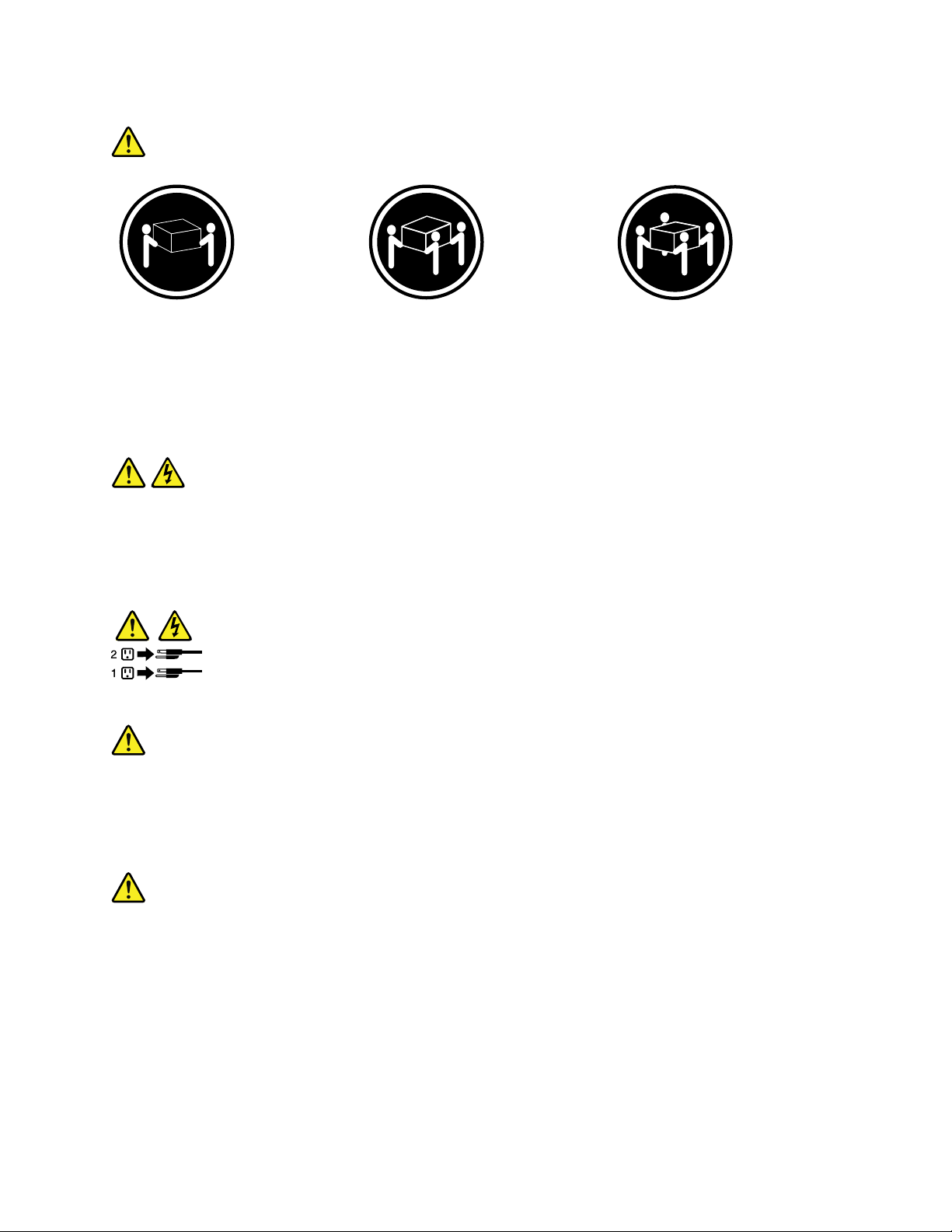
Statement4
≥18kg(39.7lb)≥32kg(70.5lb)≥55kg(121.2lb)
<32kg(70.5lb)<55kg(121.2lb)<100kg(220.5lb)
CAUTION:
Usesafepracticeswhenlifting.
Statement5
CAUTION:
Thepowercontrolbuttononthedeviceandthepowerswitchonthepowersupplydonotturnoff
theelectricalcurrentsuppliedtothedevice.Thedevicealsomighthavemorethanonepower
cord.T oremoveallelectricalcurrentfromthedevice,ensurethatallpowercordsaredisconnected
fromthepowersource.
Statement6
CAUTION:
Ifyouinstallastrain-reliefbracketoptionovertheendofthepowercordthatisconnectedtothe
device,youmustconnecttheotherendofthepowercordtoaneasilyaccessiblepowersource.
Statement7
CAUTION:
Ifthedevicehasdoors,besuretoremoveorsecurethedoorsbeforemovingorliftingthedeviceto
avoidpersonalinjury.Thedoorswillnotsupporttheweightofthedevice.
Chapter1.Aboutthismanual5
Page 12
Statement8
CAUTION:
Neverremovethecoveronapowersupplyoranypartthathasthefollowinglabelattached.
Hazardousvoltage,current,andenergylevelsarepresentinsideanycomponentthathasthislabel
attached.Therearenoserviceablepartsinsidethesecomponents.Ifyoususpectaproblemwith
oneoftheseparts,contactaservicetechnician.
Statement9
CAUTION:
Toavoidpersonalinjury,disconnectthehot-swapfancablesbeforeremovingthefanfromthedevice.
Statement10
CAUTION:
Thefollowinglabelindicatessharpedges,corners,orjointsnearby.
Statement11
CAUTION:
Thefollowinglabelindicatesahotsurfacenearby.
Statement12
DANGER
Overloadingabranchcircuitispotentiallyarehazardandashockhazardundercertainconditions.T oavoid
thesehazards,ensurethatyoursystemelectricalrequirementsdonotexceedbranchcircuitprotection
requirements.Refertotheinformationthatisprovidedwithyourdeviceforelectricalspecications.
6ThinkServerTD230HardwareMaintenanceManual
Page 13
Statement13
CAUTION:
Makesurethattherackissecuredproperlytoavoidtippingwhentheserverunitisextended.
Statement14
CAUTION:
SomeaccessoryoroptionboardoutputsexceedClass2orlimitedpowersourcelimitsandmustbe
installedwithappropriateinterconnectingcablinginaccordancewiththenationalelectriccode.
Statement15
CAUTION:
Thepower-controlbuttononthedevicedoesnotturnofftheelectricalcurrentsuppliedtothe
device.Thedevicealsomighthavemorethanoneconnectiontodcpower.Toremoveallelectrical
currentfromthedevice,ensurethatallconnectionstodcpoweraredisconnectedatthedcpower
inputterminals.
Statement16
CAUTION:
Toreducetheriskofelectricshockorenergyhazards:
•Thisequipmentmustbeinstalledbytrainedservicepersonnelinarestricted-accesslocation,as
denedbytheNECandthelatesteditionofIEC60950,TheStandardforSafetyofInformation
TechnologyEquipment.
•Connecttheequipmenttoareliablygroundedsafetyextralowvoltage(SEL V)source.AnSEL V
sourceisasecondarycircuitthatisdesignedsothatnormalandsinglefaultconditionsdonot
causethevoltagestoexceedasafelevel(60Vdirectcurrent).
•Thebranchcircuitovercurrentprotectionmustberatedinaccordancewithlocalbuildingcodes.
•Use16AmericanWireGauge(AWG)or1.3mm
2
copperconductoronly,notexceeding3meters
inlength.
•Torquethewiring-terminalscrewsto12inch-pounds(1.4newton-meters).
•Incorporateareadilyavailableapprovedandrateddisconnectdeviceintheeldwiring.
Statement17
CAUTION:
ThisproductcontainsaClass1Mlaser.Donotviewdirectlywithopticalinstruments.
Chapter1.Aboutthismanual7
Page 14
Statement18
CAUTION:
Donotplaceanyobjectontopofrack-mounteddevices.
Statement19
CAUTION:
Hazardousmovingparts.Keepngersandotherbodypartsaway.
Statement20
CAUTION:
Thebatteryisalithiumionbattery.T oavoidpossibleexplosion,donotburnthebattery.Exchangeit
onlywiththeLenovo-approvedpart.Recycleordiscardthebatteryasinstructedbylocalregulations.
ImportantinformationaboutreplacingRoHScompliantFRUs
RoHS,TheRestrictionofHazardousSubstancesinElectricalandElectronicEquipmentDirective
(2002/95/EC)isaEuropeanUnionlegalrequirementaffectingtheglobalelectronicsindustry.RoHS
requirementsmustbeimplementedonLenovoproductsplacedonthemarketandsoldinthe
EuropeanUnionafterJune2006.ProductsonthemarketbeforeJune2006arenotrequiredto
haveRoHScompliantparts.Ifthepartsarenotcompliantoriginally,replacementpartscanalso
benoncompliant,butinallcases,ifthepartsarecompliant,thereplacementpartsmustalsobe
compliant.
Note:RoHSandnon-RoHSFRUpartnumberswiththesametandfunctionareidentiedwithunique
FRUpartnumbers.
LenovoplanstotransitiontoRoHScompliancewellbeforetheimplementationdateandexpectsitssuppliers
tobereadytosupportLenovo'srequirementsandscheduleintheEU.Productssoldin2005willcontain
someRoHScompliantFRUs.ThefollowingstatementpertainstotheseproductsandanyproductLenovo
producescontainingRoHScompliantparts.
8ThinkServerTD230HardwareMaintenanceManual
Page 15
RoHScompliantThinkServer™TD230partshaveuniqueFRUpartnumbers.BeforeorafterJune2006,failed
RoHScompliantpartsmustalwaysbereplacedusingRoHScompliantFRUs,soonlytheFRUsidentiedas
compliantinthesystemHardwareMaintenanceManualordirectsubstitutionsforthoseFRUscanbeused.
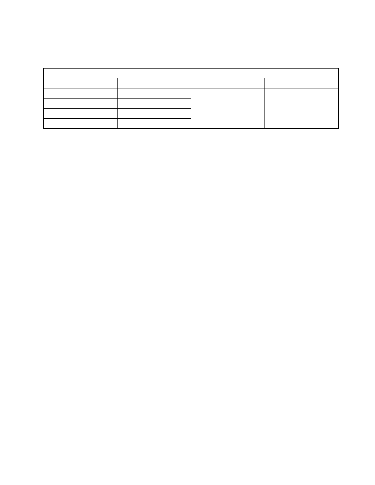
ProductsmarketedbeforeJune2006ProductsmarketedafterJune2006
Currentororiginalpart
Non-RoHSCanbeNon-RoHS
Non-RoHSCanbeRoHS
Non-RoHSCansubtoRoHS
RoHSMustbeRoHS
ReplacementFRU
Currentororiginalpart
MustbeRoHSMustbeRoHS
ReplacementFRU
Note:AdirectsubstitutionisapartwithadifferentFRUpartnumberthatisautomaticallyshippedbythe
distributioncenteratthetimeoforder.
Chapter1.Aboutthismanual9
Page 16

10ThinkServerTD230HardwareMaintenanceManual
Page 17

Chapter2.Generalinformation
Thischapterprovidessomegeneralinformationaboutyourserver.
Featuresandspecications
Thefollowingtableprovidesinformationaboutthefeaturesandspecicationsoftheserver.Depending
ontheservermodel,somefeaturesmightnotbeavailable,orsomespecicationsmightnotapply.For
informationaboutyourspecicmodel,usetheSetupUtilityprogram.See“UsingtheSetupUtilityprogram”
onpage143
Table1.Featuresandspecications
.
Microprocessor(s):SupportsuptotwoIntel®Xeon®
dual-core,quad-core,orhex-coremicroprocessors
(internalcachesizevariesbymodeltype)Forthe
specictypeandspeedinformationaboutthe
microprocessor,usetheSetupUtilityprogram.
See“UsingtheSetupUtilityprogram”onpage
143.Foralistofsupportedmicroprocessors,goto
http://www.lenovo.com/thinkserverandclickOptions
undertheProductstab.
Largesystem-memorycapacity:
•Supportsuptoeightmemorymodules
•Minimumsystemmemory:2GB
•Maximumsystemmemory:32GB(eachmemoryslot
withone4GBmemorymoduleinstalled)
•Memoryslots:Eightdualinlinememorymodule
(DIMM)slots
•Types:1333MHz,DDR3registeredSDRAMDIMMs
•Features:
–ErrorCheckingandCorrecting(ECC)
–Mirroring
–DemandScrubandPatrolScrub
•Supports2GBand4GBregisteredDIMMs
•NumbersofDIMMssupported:
–One,two,orfourDIMMsifonemicroprocessor
installed
–Two,four,six,oreightDIMMsiftwomicroprocessors
installed
Integratedvideocontroller:
anonboardhigh-performancegraphicscontroller
thatsupportshighresolutionsandincludesmany
performance-enhancingfeaturesfortheoperating-system
environment.
•64MBmemory,32MBforvideomemorycache
Theservercomeswith
Opticaldrive:
•SATADVD/RW
Harddiskdriveexpansionbays(dependingonmodel
type):
Supportsuptofour3.5-inchSerialAdvancedTechnology
Attachment(SATA)orSAShot-swapharddiskdrives
Supportsuptove3.5-inchSATAnon-hot-swaphard
diskdrives
Largedata-storagecapacityandhot-swapcapability
Someservermodelssupportuptofour3.5-inchhot-swap
harddiskdrives.Withthehot-swapfeature,youcanadd,
remove,orreplaceharddiskdriveswithoutturningoff
theserver.
Expansionslots(dependingonmodeltype):
•OnePeripheralComponentInterconnect(PCI)cardslot
•OnePCIExpressx4cardslot
•ThreePCIExpressx8cardslots
•Oneremotemanagementmodule3connector
Powersupply:
625-wattpowersupply
Systemfans:
•Twofrontsystemfans(systemfan2formicroprocessor
1areaandsystemfan1formicroprocessor2area)
•Onerearsystemfan
©CopyrightLenovo2010,2011
RAIDcontrollers:
TheserversupportsanonboardSATAsoftwareRAID.
aThinkServerRAID500Adapter,oraThinkServer
8708EM2RAIDAdapter,whicharerequiredforyoutouse
thehot-swapSATAorSASharddiskdrivesandtocreate
theRAIDcongurations.
•OnboardICH10RSATAcontroller
11
Page 18
Table1.Featuresandspecications(continued)
Integratedfunctions:
•Ethernetcontrollers(Theservercomeswithtwo
integratedGigabitEthernetcontrollers,whichsupport
connectionto10Mbps,100Mbps,or1000Mbps
network.Formoreinformation,see“Conguringthe
GigabitEthernetcontroller”onpage157
•Oneserialport
•OneVideoGraphicsArray(VGA)monitorconnector
•SixUniversalSerialBus(USB)connectors(twofront
andfourrear)
•TwoRJ-45Ethernetconnectorsontherearpanel
•EightdiagnosticLEDs
IntelligentPlatformManagementInterface(IPMI)2.0
Thecommand-lineinterfaceprovidesdirectaccess
toservermanagementfunctionsthroughtheIPMI2.0
protocol.Usethecommand-lineinterfacetoissue
commandstocontroltheserverpower,viewsystem
information,andidentifytheserver.Y oucanalsosave
oneormorecommandsasatextleandruntheleasa
script.
ThinkServerRMM3SystemManagementCard
(Optional)
.)
•ThinkServerRAID500Adapter(9240-8i)
•ThinkServer8708EM2RAIDAdapter
Size:
•Height:470mm(18.5inches)
•Width:210mm(8.27inches)
•Depth:510mm(20.1inches)
•Maximumweightwithpackage:26.2kg(57.76lb)
whenfullycongured
•Maximumweightwithoutpackage:22.3kg(49.2lb)
whenfullycongured
Electricalinput
•Inputvoltage:
–Lowrange:
Minimum:100Vac
Maximum:127Vac
Inputfrequencyrange:50to60Hz
–Highrange:
Minimum:200Vac
Maximum:240Vac
Inputfrequencyrange:50to60Hz
Softwareprograms
Lenovoprovidessoftwaretohelpgetyourserverupandrunning.
EasyStartup
TheThinkServerEasyStartupprogramsimpliestheprocessofconguringRAIDandinstallingsupported
Microsoft®Windows®andLinux®operatingsystemsanddevicedriversonyourserver.TheEasyStartup
programisprovidedwithyourserverontheThinkServerEasyStartupDVD.TheDVDisself-starting(bootable).
TheuserguidefortheEasyStartupprogramisontheDVDandcanbeaccesseddirectlyfromtheprogram
interface.Foradditionalinformation,see“UsingtheThinkServerEasyStartupprogram”onpage151
.
EasyManage
TheThinkServerEasyManageAgentenablesthisservertobemanagedbythecentralizedconsoleofan
EasyManageCoreServeroverthenetwork.TheThinkServerEasyManageAgentissupportedon32-bitand
64-bitWindows,RedHat,andSUSEoperatingsystems.
Reliability,availability,andserviceability
Reliability,availability,andserviceability(hereafterreferredtoasRAS)arethreeimportantserverdesign
features.TheRASfeatureshelpyoutoensuretheintegrityofthedatastoredontheserver,theavailabilityof
theserverwhenyouneedit,andtheeasewithwhichyoucandiagnoseandcorrectproblems.
TheserverhasthefollowingRASfeatures:
•AdvancedCongurationandPowerInterface(ACPI)
12ThinkServerTD230HardwareMaintenanceManual
Page 19

•AdvancedDesktopManagementInterface(DMI)
•Automaticmemorydownsizingonerrordetection
•Automaticrestartonnon-maskableinterrupt(NMI)
•Availabilityofmicrocodelevel
•Built-in,menu-drivensetup,systemconguration,andRAIDconguration
•Built-inmonitoringforfan,temperature,andvoltage
•Coolingfanswithspeed-sensingcapability
•ECCDDR3SDRAMwithSerialPresenceDetect(SPD)
•Errorcodesandmessagestohelpyouidentifyproblems
•Generatingerrorlogsforthepower-onself-test(POST)failures
•Hot-swapSASharddiskdrives
•IntegratedEthernetcontrollers
•IntelligentPlatformManagementInterface(IPMI)2.0
•Power-onself-test(POST)
•Standbyvoltageforsystem-managementfeaturesandmonitoring
•System-errorlight-emittingdiode(LED)onthefrontpanel
•Vitalproductdata(VPD),includingtheserialnumberinformationandreplacementpartnumbers,storedin
thenonvolatilememoryforeasierremotemaintenance
Chapter2.Generalinformation13
Page 20

14ThinkServerTD230HardwareMaintenanceManual
Page 21
Chapter3.Diagnostics
Thischapterdescribesthediagnostictoolsthatareavailabletohelpyousolveproblemsthatmightoccurin
theserver.
Ifyoucannotdiagnoseandcorrectaproblembyusingtheinformationinthischapter,seeAppendixB
“Gettinghelpandtechnicalassistance”onpage163
Troubleshootingtables
Usethetroubleshootingtablestondsolutionstoproblemsthathaveidentiablesymptoms.
Ifyouhavejustaddednewsoftwareoranewoptionaldeviceandtheserverisnotworking,completethe
followingstepsbeforeyouusethetroubleshootingtables:
1.Checktheoperatorinformationpanel.
2.Removethesoftwareordevicethatyoujustadded.
3.Reinstallthenewsoftwareornewdevice.
DVDdriveproblems
•FollowthesuggestedactionsintheorderinwhichtheyarelistedintheActioncolumnuntiltheproblemis
solved.
•SeethepartslistingintheHardwareMaintenanceManualtodeterminewhichcomponentsarecustomer
replaceableunits(CRUs)andwhichcomponentsareeldreplaceableunits(FRUs).
•Ifanactionstepisprecededby“(T rainedservicetechnicianonly),”thatstepmustbeperformedonlyby
atrainedservicetechnician.
formoreinformation.
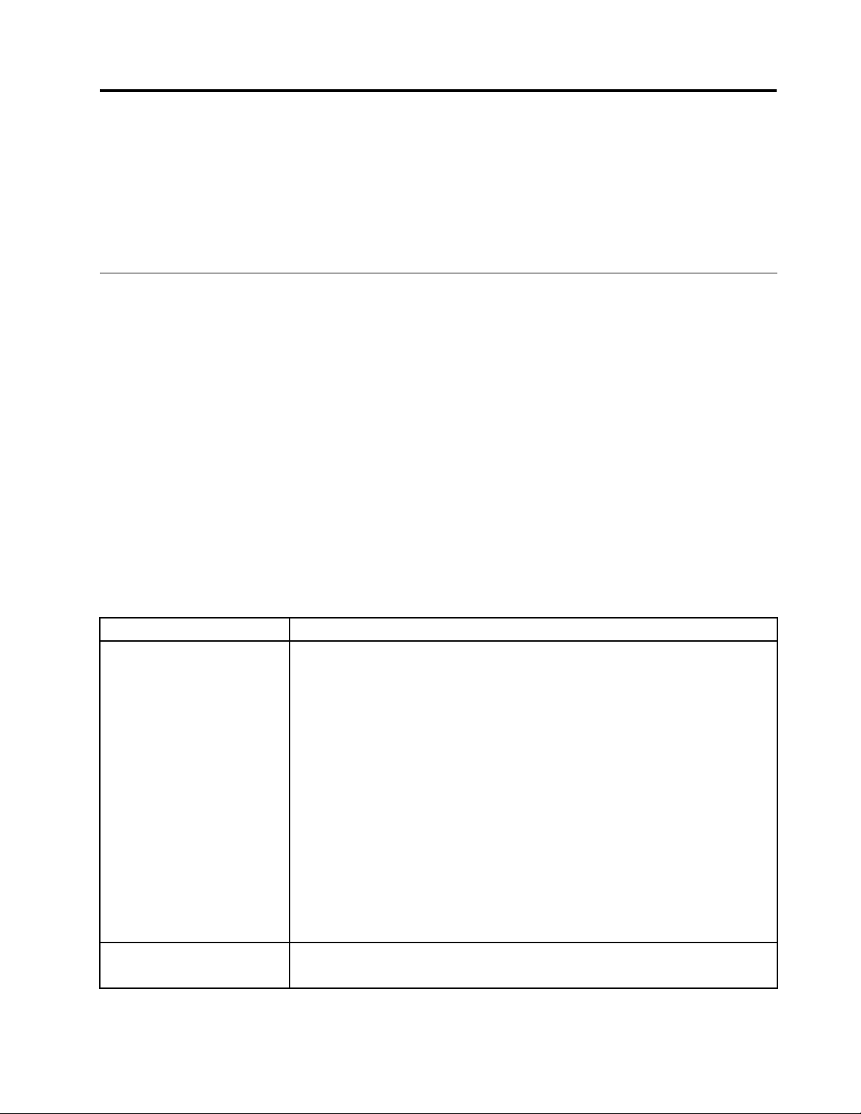
SymptomAction
TheDVDdriveisnot
recognized.
ADVDisnotworkingcorrectly.
1.Makesurethat:
•TheSATAchanneltowhichtheDVDdriveisattached(primaryorsecondary)
isenabledintheSetupUtilityprogram.
•Allcablesandjumpersareinstalledcorrectly.
•Thesignalcableandconnectorarenotdamagedandtheconnectorpins
arenotbent.
•ThecorrectdevicedriverisinstalledfortheDVDdrive.
2.Reseatthefollowingcomponents:
a.DVDdrive
b.DVDdrivecables
3.Replacethefollowingcomponentsoneatatime,intheordershown,restarting
theservereachtime:
a.DVDdrive
b.DVDdriveandcables
c.(T rainedservicetechnicianonly)Systemboard
1.CleantheDVD.
2.ReseattheDVDdrive.
©CopyrightLenovo2010,2011
15
Page 22
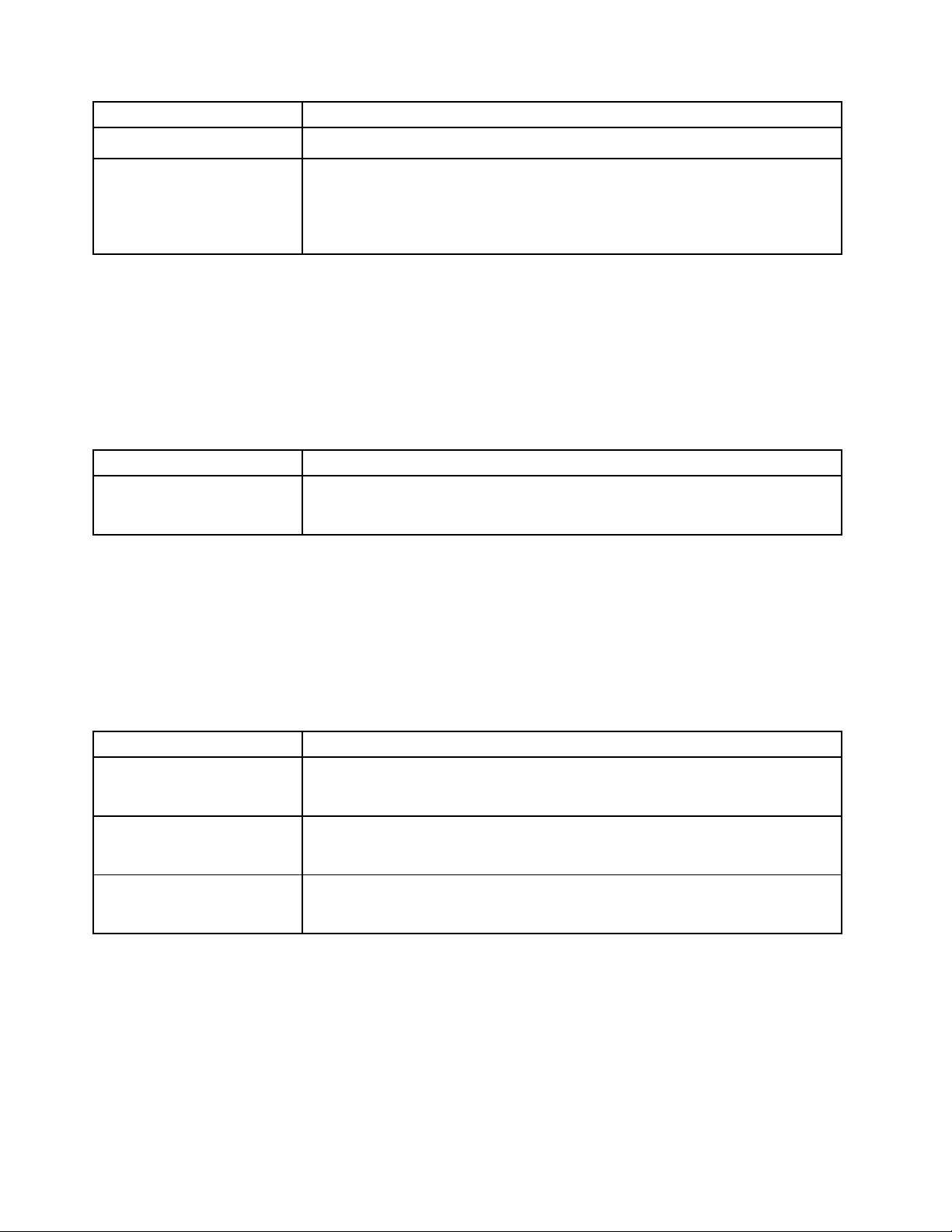
SymptomAction
3.ReplacetheDVDdrive.
TheDVDdrivetrayisnot
working.
1.Makesurethattheserveristurnedon.
2.Inserttheendofastraightenedpaperclipintothemanualtray-releaseopening.
3.ReseattheDVDdrive.
4.ReplacetheDVDdrive.
Generalproblems
•FollowthesuggestedactionsintheorderinwhichtheyarelistedintheActioncolumnuntiltheproblemis
solved.
•SeethepartslistingintheHardwareMaintenanceManualtodeterminewhichcomponentsarecustomer
replaceableunits(CRUs)andwhichcomponentsareeldreplaceableunits(FRUs).
•Ifanactionstepisprecededby“(T rainedservicetechnicianonly),”thatstepmustbeperformedonlyby
atrainedservicetechnician.
SymptomAction
Acoverlockisbroken,anLED
isnotworking,orasimilar
problemhasoccurred.
IfthepartisaCRU,replaceit.IfthepartisaFRU,thepartmustbereplacedbya
trainedservicetechnician.
Harddiskdriveproblems
•FollowthesuggestedactionsintheorderinwhichtheyarelistedintheActioncolumnuntiltheproblemis
solved.
•SeethepartslistingintheHardwareMaintenanceManualtodeterminewhichcomponentsarecustomer
replaceableunits(CRUs)andwhichcomponentsareeldreplaceableunits(FRUs).
•Ifanactionstepisprecededby“(T rainedservicetechnicianonly),”thatstepmustbeperformedonlyby
atrainedservicetechnician.
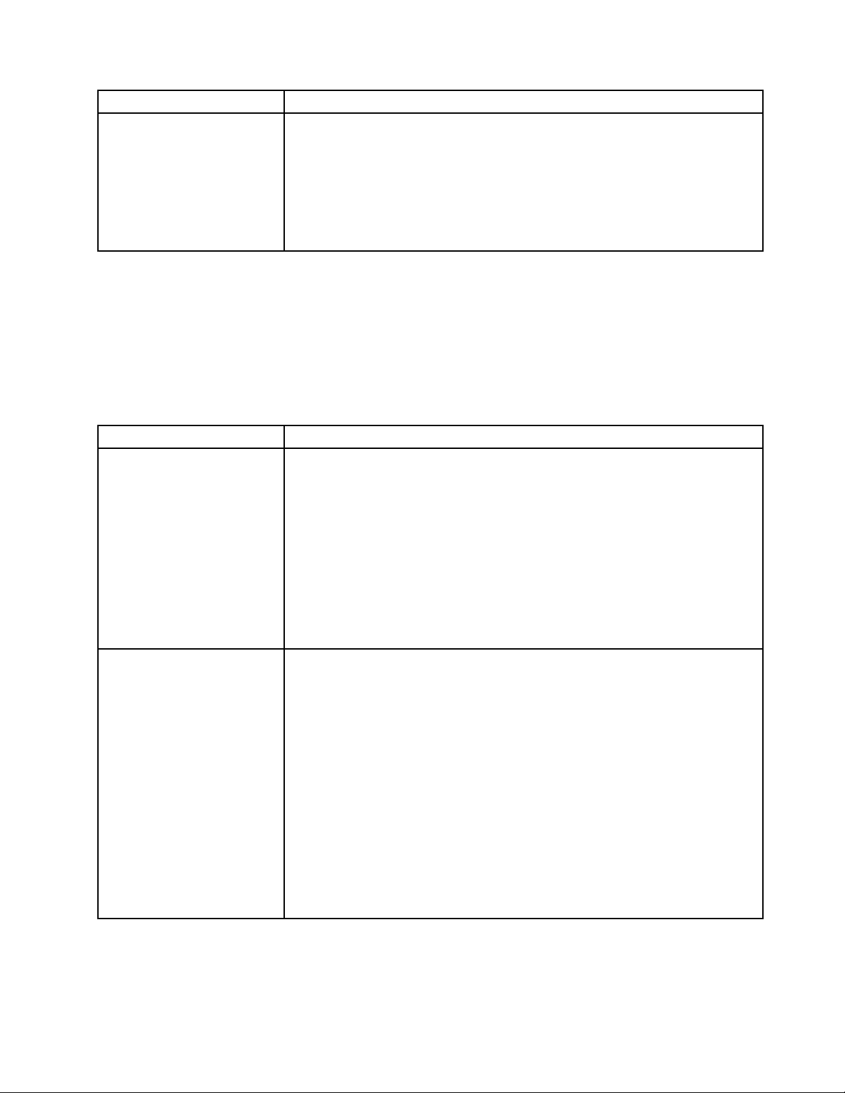
SymptomAction
Notalldrivesarerecognizedby
theharddiskdrivediagnostic
tests.
Theserverstopsresponding
duringtheharddiskdrive
diagnostictest.
Aharddiskdrivewasnot
detectedwhiletheoperating
systemwasbeingstarted.
Removethedrivethatisindicatedbythediagnostictests;then,runtheharddisk
drivediagnostictestsagain.Iftheremainingdrivesarerecognized,replacethe
drivethatyouremovedwithanewone.
Removetheharddiskdrivethatwasbeingtestedwhentheserverstopped
responding,andrunthediagnostictestagain.Iftheharddiskdrivediagnostictest
runssuccessfully,replacethedrivethatyouremovedwithanewone.
Reseatallharddiskdrivesandcables;then,runtheharddiskdrivediagnostic
testsagain.
Intermittentproblems
•FollowthesuggestedactionsintheorderinwhichtheyarelistedintheActioncolumnuntiltheproblemis
solved.
•SeethepartslistingintheHardwareMaintenanceManualtodeterminewhichcomponentsarecustomer
replaceableunits(CRUs)andwhichcomponentsareeldreplaceableunits(FRUs).
•Ifanactionstepisprecededby“(T rainedservicetechnicianonly),”thatstepmustbeperformedonlyby
atrainedservicetechnician.
16ThinkServerTD230HardwareMaintenanceManual
Page 23
SymptomAction
Aproblemoccursonly
occasionallyandisdifcultto
diagnose.
1.Makesurethat:
•Allcablesandcordsareconnectedsecurelytotherearoftheserverand
attacheddevices.
•Whentheserveristurnedon,airisowingfromthefangrille.Ifthereis
noairow,thefanisnotworking.Thiscancausetheservertooverheat
andshutdown.
2.Checkthesystem-eventlog(see“Eventlogs”onpage25).
3.See“Solvingundeterminedproblems”onpage24.
Keyboard,mouse,orpointing-deviceproblems
•FollowthesuggestedactionsintheorderinwhichtheyarelistedintheActioncolumnuntiltheproblemis
solved.
•SeethepartslistingintheHardwareMaintenanceManualtodeterminewhichcomponentsarecustomer
replaceableunits(CRUs)andwhichcomponentsareeldreplaceableunits(FRUs).
•Ifanactionstepisprecededby“(T rainedservicetechnicianonly),”thatstepmustbeperformedonlyby
atrainedservicetechnician.
SymptomAction
Allorsomekeysonthe
keyboarddonotwork.
Themouseorpointingdevice
doesnotwork.
1.Makesurethat:
•Thekeyboardcableissecurelyconnected.
•Theserverandthemonitorareturnedon.
2.Thekeyboardiscompatiblewiththeserver.RefertotheWebsiteat
http://www.lenovo.com/thinkserver.
3.IfyouareusingaUSBkeyboardanditisconnectedtoaUSBhub,disconnect
thekeyboardfromthehubandconnectitdirectlytotheserver.
4.Replacethefollowingcomponentsoneatatime,intheordershown,restarting
theservereachtime:
a.Keyboard
b.(Trainedservicetechnicianonly)Systemboard
1.Makesurethat:
•Themouseorpointingdeviceiscompatiblewiththeserver.RefertotheWeb
siteathttp://www.lenovo.com/thinkserver.
•Themouseorpointing-devicecableissecurelyconnectedtotheserver.
•Themouseorpointing-devicedevicedriversareinstalledcorrectly.
•Theserverandthemonitorareturnedon.
•ThemouseisenabledintheSetupUtilityprogram.
2.IfyouareusingaUSBmouseorpointingdeviceanditisconnectedtoaUSB
hub,disconnectthemouseorpointingdevicefromthehubandconnectit
directlytotheserver.
3.Replacethefollowingcomponentsoneatatime,intheordershown,restarting
theservereachtime:
a.Mouseorpointingdevice
b.(Trainedservicetechnicianonly)Systemboard
Memoryproblems
•FollowthesuggestedactionsintheorderinwhichtheyarelistedintheActioncolumnuntiltheproblemis
solved.
Chapter3.Diagnostics17
Page 24
•SeethepartslistingintheHardwareMaintenanceManualtodeterminewhichcomponentsarecustomer
replaceableunits(CRUs)andwhichcomponentsareeldreplaceableunits(FRUs).
•Ifanactionstepisprecededby“(T rainedservicetechnicianonly),”thatstepmustbeperformedonlyby
atrainedservicetechnician.
SymptomAction
Theamountofsystemmemory
thatisdisplayedislessthan
theamountofinstalledphysical
memory.
MultiplerowsofDIMMsina
branchareidentiedasfailing.
1.Makesurethat:
•NoerrorLEDsarelitontheoperatorinformationpanelorontheDIMM.
•Memorymirroringdoesnotaccountforthediscrepancy.
•Thememorymodulesareseatedcorrectly.
•Youhaveinstalledthecorrecttypeofmemory.
•Ifyouchangedthememory,youupdatedthememorycongurationinthe
SetupUtilityprogram.
•Allbanksofmemoryareenabled.Theservermighthaveautomatically
disabledamemorybankwhenitdetectedaproblem,oramemorybank
mighthavebeenmanuallydisabled.
2.CheckthePOSTeventlogforDIMMerrormessages:
•IfaDIMMwasdisabledbyasystems-managementinterrupt(SMI),replace
theDIMM.
•IfaDIMMwasdisabledbytheuserorbyPOST,runtheSetupUtilityprogram
andenabletheDIMM.
3.Makesurethatthereisnomemorymismatchwhentheserverisattheminimum
memoryconguration.
4.AddonepairofDIMMsatatime,makingsurethattheDIMMsineachpair
arematching.
5.ReseattheDIMMs.
6.ReplacetheDIMMsinstep5onpage18,oneatatime,intheordershown,
restartingtheservereachtime.
1.ReseattheDIMMs;then,restarttheserver.
2.Replacethelowest-numberedDIMMswithidenticalknowngoodDIMMs;
then,restarttheserver.Repeatasnecessary.Ifthefailurescontinueafterall
identiedpairsarereplaced,gotostep4onpage18.
3.ReturntheremovedDIMMs,onepairatatime,totheiroriginalconnectors,
restartingtheserveraftereachpair,untilapairfails.ReplaceeachDIMMinthe
failedpairwithanidenticalknowngoodDIMM,restartingtheserverafteryou
reinstalleachDIMM.ReplacethefailedDIMM.Repeatstep3onpage18
youhavetestedallremovedDIMMs.
4.(Trainedservicetechnicianonly)Replacethesystemboard.
until
Microprocessorproblems
•FollowthesuggestedactionsintheorderinwhichtheyarelistedintheActioncolumnuntiltheproblemis
solved.
•SeethepartslistingintheHardwareMaintenanceManualtodeterminewhichcomponentsarecustomer
replaceableunits(CRUs)andwhichcomponentsareeldreplaceableunits(FRUs).
•Ifanactionstepisprecededby“(T rainedservicetechnicianonly),”thatstepmustbeperformedonlyby
atrainedservicetechnician.
18ThinkServerTD230HardwareMaintenanceManual
Page 25
SymptomAction
Theserveremitsacontinuous
beepduringthePOST,
indicatingthatthestartup
(boot)microprocessorisnot
workingcorrectly.
1.Makesurethattheserversupportsallthemicroprocessorsandthatthe
microprocessorsmatchinspeedandcachesize.
2.(Trainedservicetechnicianonly)Reseatmicroprocessor1.
3.(Trainedservicetechnicianonly)Ifthereisnoindicationofwhichmicroprocessor
hasfailed,isolatetheerrorbytestingwithonemicroprocessoratatime.
4.Replacethefollowingcomponentsoneatatime,intheordershown,restarting
theservereachtime:
a.(T rainedservicetechnicianonly)Microprocessor2
b.VRM2
c.(T rainedservicetechnicianonly)Systemboard
5.(Trainedservicetechnicianonly)Ifmultipleerrorcodesindicateamicroprocessor
error,reversethelocationsoftwomicroprocessorstodeterminewhetherthe
errorisassociatedwithamicroprocessororwithamicroprocessorsocket.
•Iftheerrorisassociatedwithamicroprocessor,replacethemicroprocessor.
•IftheerrorisassociatedwithaVRM,replacetheVRM.
•Iftheerrorisassociatedwithamicroprocessorsocket,replacethesystem
board.
Monitorproblems
Somemonitorshavetheirownself-tests.Ifyoususpectaproblemwithyourmonitor,seethedocumentation
thatcomeswiththemonitorforinstructionsfortestingandadjustingthemonitor.
•FollowthesuggestedactionsintheorderinwhichtheyarelistedintheActioncolumnuntiltheproblemis
solved.
•SeethepartslistingintheHardwareMaintenanceManualtodeterminewhichcomponentsarecustomer
replaceableunits(CRUs)andwhichcomponentsareeldreplaceableunits(FRUs).
•Ifanactionstepisprecededby“(T rainedservicetechnicianonly),”thatstepmustbeperformedonlyby
atrainedservicetechnician.
SymptomAction
Testingthemonitor
Thescreenisblank.
1.Makesurethatthemonitorcablesarermlyconnected.
2.Tryusingadifferentmonitorontheserver,ortryusingthemonitorthatisbeing
testedonadifferentserver.
3.Runthediagnosticprograms.Ifthemonitorpassesthediagnosticprograms,
theproblemmightbeavideodevicedriver.
4.(Trainedservicetechnicianonly)Replacethesystemboard.
1.IftheserverisattachedtoaKVMswitch,bypasstheKVMswitchtoeliminateit
asapossiblecauseoftheproblem:connectthemonitorcabledirectlytothe
correctconnectorontherearoftheserver.
2.Makesurethat:
•Theserveristurnedon.Ifthereisnopowertotheserver,see“Power
problems”onpage21
•Themonitorcablesareconnectedcorrectly.
•Themonitoristurnedonandthebrightnessandcontrastcontrolsare
adjustedcorrectly.
•NoPOSTerrorsaregeneratedwhentheserveristurnedon.
3.Makesurethatthecorrectserveriscontrollingthemonitor,ifapplicable.
4.See“Solvingundeterminedproblems”onpage24.
.
Chapter3.Diagnostics19
Page 26
SymptomAction
Themonitorhasscreen
jitter,orthescreenimageis
wavy,unreadable,rolling,or
distorted.
Wrongcharactersappearon
thescreen.
1.Ifthemonitorself-testsshowthatthemonitorisworkingcorrectly,consider
thelocationofthemonitor.Magneticeldsaroundotherdevices(suchas
transformers,appliances,uorescentlights,andothermonitors)cancause
screenjitterorwavy,unreadable,rolling,ordistortedscreenimages.Ifthis
happens,turnoffthemonitor.
Attention:Movingacolormonitorwhileitisturnedonmightcausescreen
discoloration.
Movethedeviceandthemonitoratleast305mm(12inches)apart,andturnon
themonitor.
Topreventdiskettedriveread/writeerrors,makesurethatthedistancebetween
themonitorandanyexternaldiskettedriveisatleast76mm(3inches).
2.Reseatthemonitor.
3.Replacethefollowingcomponentsoneatatime,intheordershown,restarting
theservereachtime:
a.Monitor
b.(Trainedservicetechnicianonly)Systemboard
1.Ifthewronglanguageisdisplayed,updatetheserverrmwarewiththecorrect
language(see“Updatingthermware”onpage158
2.Reseatthemonitor.
3.Replacethefollowingcomponentsoneatatime,intheordershown,restarting
theservereachtime:
a.Monitor
b.(Trainedservicetechnicianonly)Systemboard
).
Optional-deviceproblems
•FollowthesuggestedactionsintheorderinwhichtheyarelistedintheActioncolumnuntiltheproblemis
solved.
•SeethepartslistingintheHardwareMaintenanceManualtodeterminewhichcomponentsarecustomer
replaceableunits(CRUs)andwhichcomponentsareeldreplaceableunits(FRUs).
•Ifanactionstepisprecededby“(T rainedservicetechnicianonly),”thatstepmustbeperformedonlyby
atrainedservicetechnician.
SymptomAction
ALenovooptionaldevicethat
wasjustinstalleddoesnot
work.
1.Makesurethat:
•Thedeviceisdesignedfortheserver.Foralistofthesupportedoptionsfor
yourserver,gotohttp://www.lenovo.com/thinkserver.OntheThinkServer
systemspage,clickProducts➙Options.
•Youfollowedtheinstallationinstructionsthatcamewiththedeviceandthe
deviceisinstalledcorrectly.
•Youhavenotloosenedanyotherinstalleddevicesorcables.
•YouupdatedthecongurationinformationintheSetupUtilityprogram.
Whenevermemoryoranyotherdeviceischanged,youmustupdatethe
conguration.
2.Reseatthedevicethatyoujustinstalled.
20ThinkServerTD230HardwareMaintenanceManual
Page 27
SymptomAction
3.Replacethedevicethatyoujustinstalled.
ALenovooptionaldevicethat
usedtoworkdoesnotwork
now.
1.Makesurethatallofthehardwareandcableconnectionsforthedeviceare
secure.
2.Ifthedevicecomeswithtestinstructions,usethoseinstructionstotestthe
device.
3.IfthefailingdeviceisanSCSIdevice,makesurethat:
•ThecablesforallexternalSCSIdevicesareconnectedcorrectly.
•ThelastdeviceineachSCSIchain,ortheendoftheSCSIcable,is
terminatedcorrectly.
•AnyexternalSCSIdeviceisturnedon.Y oumustturnonanexternalSCSI
devicebeforeyouturnontheserver.
4.Reseatthefailingdevice.
5.Replacethefailingdevice.
Powerproblems
•FollowthesuggestedactionsintheorderinwhichtheyarelistedintheActioncolumnuntiltheproblemis
solved.
•SeethepartslistingintheHardwareMaintenanceManualtodeterminewhichcomponentsarecustomer
replaceableunits(CRUs)andwhichcomponentsareeldreplaceableunits(FRUs).
•Ifanactionstepisprecededby“(T rainedservicetechnicianonly),”thatstepmustbeperformedonlyby
atrainedservicetechnician.
SymptomAction
Thepower-controlbuttondoes
notwork(theserverdoesnot
start).
Note:Thepower-control
buttonwillnotfunctionuntil
3minutesaftertheserverhas
beenconnectedtoacpower.
1.Makesurethatthepower-controlbuttonisworkingcorrectly:
a.Disconnecttheserverpowercords.
b.Reconnectthepowercords.
c.(T rainedservicetechnicianonly)Reseattheoperatorinformationpanel
cables,andthenrepeatstepa.onpage22
serverstarts,reseattheoperatorinformationpanel.Iftheproblemremains,
replacetheoperatorinformationpanel.
2.Makesurethat:
•Thepowercordsarecorrectlyconnectedtotheserverandtoaworking
electricaloutlet.
•Thetypeofmemorythatisinstallediscorrect.
•TheDIMMisfullyseated.
•TheLEDsonthepowersupplydonotindicateaproblem.
•Themicroprocessorsareinstalledinthecorrectsequence.
3.Reseatthefollowingcomponents:
a.DIMMs
b.(Trainedservicetechnicianonly)Powerswitchconnector
c.(T rainedservicetechnicianonly)Powerbackplane
4.Replacethefollowingcomponentsoneatatime,intheordershown,restarting
theservereachtime:
a.DIMMs
b.(Trainedservicetechnicianonly)Powerswitchconnector
c.(T rainedservicetechnicianonly)Powerbackplane
d.(Trainedservicetechnicianonly)Systemboard
andstepb.onpage22.Ifthe
Chapter3.Diagnostics21
Page 28
SymptomAction
Theserverdoesnotturnoff.
Theserverunexpectedlyshuts
down,andtheLEDsonthe
operatorinformationpanelare
notlit.
Serialportproblems
5.Ifyoujustinstalledanoptionaldevice,removeit,andrestarttheserver.If
theservernowstarts,youmighthaveinstalledmoredevicesthanthepower
supplysupports.
6.See“Solvingundeterminedproblems”onpage24.
1.DeterminewhetheryouareusinganAdvancedCongurationandPower
Interface(ACPI)oranon-ACPIoperatingsystem.Ifyouareusinganon-ACPI
operatingsystem,dothefollowing:
a.PressCtrl+Alt+Delete.
b.Turnofftheserverbypressingthepower-controlbuttonfor5seconds.
c.Restarttheserver.
d.IftheserverfailsthePOSTandthepower-controlbuttondoesnotwork,
disconnectthepowercordfor20seconds;then,reconnectthepowercord
andrestarttheserver.
2.IftheproblemremainsorifyouareusinganACPI-awareoperatingsystem,
suspectthesystemboard.
See“Solvingundeterminedproblems”onpage24
.
•FollowthesuggestedactionsintheorderinwhichtheyarelistedintheActioncolumnuntiltheproblemis
solved.
•SeethepartslistingintheHardwareMaintenanceManualtodeterminewhichcomponentsarecustomer
replaceableunits(CRUs)andwhichcomponentsareeldreplaceableunits(FRUs).
•Ifanactionstepisprecededby“(T rainedservicetechnicianonly),”thatstepmustbeperformedonlyby
atrainedservicetechnician.
SymptomAction
Thenumberofserialportsthat
areidentiedbytheoperating
systemislessthanthenumber
ofinstalledserialports.
Aserialdevicedoesnotwork.1.Makesurethat:
1.Makesurethat:
•EachportisassignedauniqueaddressintheSetupUtilityprogramand
noneoftheserialportsisdisabled.
•Theserialportadapter(ifoneispresent)isseatedcorrectly.
2.Reseattheserialportadapter.
3.Replacetheserialportadapter.
•Thedeviceiscompatiblewiththeserver.
•Theserialportisenabledandisassignedauniqueaddress.
•Thedeviceisconnectedtothecorrectconnector.
2.Reseatthefollowingcomponents:
a.Failingserialdevice
b.Serialcable
3.Replacethefollowingcomponentsoneatatime,intheordershown,restarting
theservereachtime:
a.Failingserialdevice
b.Serialcable
c.(T rainedservicetechnicianonly)Systemboard
22ThinkServerTD230HardwareMaintenanceManual
Page 29

Softwareproblems
•FollowthesuggestedactionsintheorderinwhichtheyarelistedintheActioncolumnuntiltheproblemis
solved.
•SeethepartslistingintheHardwareMaintenanceManualtodeterminewhichcomponentsarecustomer
replaceableunits(CRUs)andwhichcomponentsareeldreplaceableunits(FRUs).
•Ifanactionstepisprecededby“(T rainedservicetechnicianonly),”thatstepmustbeperformedonlyby
atrainedservicetechnician.
SymptomAction
Yoususpectasoftware
problem.
1.Todeterminewhethertheproblemiscausedbythesoftware,makesurethat:
•Theserverhastheminimummemorythatisneededtousethesoftware.For
memoryrequirements,seetheinformationthatcomeswiththesoftware.
Ifyouhavejustinstalledanadapterormemory,theservermighthavea
memory-addressconict.
•Thesoftwareisdesignedtooperateontheserver.
•Othersoftwareworksontheserver.
•Thesoftwareworksonanotherserver.
2.Ifyoureceiveanyerrormessageswhileyouusethesoftware,seethe
informationthatcomeswiththesoftwareforadescriptionofthemessagesand
suggestedsolutionstotheproblem.
3.Contactthesoftwarevendor.
UniversalSerialBus(USB)portproblems
•FollowthesuggestedactionsintheorderinwhichtheyarelistedintheActioncolumnuntiltheproblemis
solved.
•SeethepartslistingintheHardwareMaintenanceManualtodeterminewhichcomponentsarecustomer
replaceableunits(CRUs)andwhichcomponentsareeldreplaceableunits(FRUs).
•Ifanactionstepisprecededby“(T rainedservicetechnicianonly),”thatstepmustbeperformedonlyby
atrainedservicetechnician.
SymptomAction
AUSBdevicedoesnotwork.
1.Makesurethat:
•ThecorrectUSBdevicedriverisinstalled.
•TheoperatingsystemsupportsUSBdevices.
•AstandardPS/2keyboardormouseisnotconnectedtotheserver.Ifitis,a
USBkeyboardormousewillnotworkduringthePOST .
2.MakesurethattheUSBcongurationoptionaldevicesaresetcorrectlyinthe
SetupUtilityprogram.
3.IfyouareusingaUSBhub,disconnecttheUSBdevicefromthehuband
connectitdirectlytotheserver.
Solvingpowerproblems
Powerproblemscanbedifculttosolve.Forexample,ashortcircuitcanexistanywhereonanyofthe
powerdistributionbuses.Usually,ashortcircuitwillcausethepowersubsystemtoshutdownbecauseof
anovercurrentcondition.T odiagnoseapowerproblem,usethefollowinggeneralprocedure:
1.T urnofftheserveranddisconnectallacpowercords.
2.Checkforloosecablesinthepowersubsystem.Alsocheckforshortcircuits,forexample,ifaloose
screwiscausingashortcircuitonacircuitboard.
Chapter3.Diagnostics23
Page 30

3.Removetheadaptersanddisconnectthecablesandpowercordstoallinternalandexternaldevices
untiltheserverisattheminimumcongurationthatisrequiredfortheservertostart(see“Solving
undeterminedproblems”onpage24fortheminimumconguration).
4.Reconnectallacpowercordsandturnontheserver.Iftheserverstartssuccessfully,replacethe
adaptersanddevicesoneatatimeuntiltheproblemisisolated.
Iftheserverdoesnotstartfromtheminimumconguration,replacethecomponentsintheminimum
congurationoneatatimeuntiltheproblemisisolated.
SolvingEthernetcontrollerproblems
ThemethodthatyouusetotesttheEthernetcontrollerdependsonwhichoperatingsystemyouareusing.
Seetheoperating-systemdocumentationforinformationaboutEthernetcontrollers,andseetheEthernet
controllerdevice-driverreadmele.
Trythefollowingprocedures:
•Makesurethatthecorrectdevicedrivers,whichcomewiththeserver,areinstalledandthattheyareat
thelatestlevel.
•MakesurethattheEthernetcableisinstalledcorrectly.
–Thecablemustbesecurelyattachedatallconnections.Ifthecableisattachedbuttheproblem
remains,tryadifferentcable.
–IftheEthernetcontrollerissettooperateat100Mbps,youmustuseCategory5cabling.
–Ifyoudirectlyconnecttwoservers(withoutahub),orifyouarenotusingahubwithXports,usea
crossovercable.TodeterminewhetherahubhasanXport,checktheportlabel.Ifthelabelcontains
anX,thehubhasanXport.
•Determinewhetherthehubsupportsauto-negotiation.Ifitdoesnot,tryconguringtheintegrated
Ethernetcontrollermanuallytomatchthespeedandduplexmodeofthehub.
•ChecktheEthernetcontrollerLEDsontherearpaneloftheserver.TheseLEDsindicatewhetherthere
isaproblemwiththeconnector,cable,orhub.
–TheEthernetlinkstatusLEDislitwhentheEthernetcontrollerreceivesalinkpulsefromthehub.Ifthe
LEDisoff,theremightbeadefectiveconnectororcableoraproblemwiththehub.
–TheEthernettransmit/receiveactivityLEDislitwhentheEthernetcontrollersendsorreceivesdata
overtheEthernetnetwork.IftheEthernettransmit/receiveactivityLEDisoff,makesurethatthehub
andnetworkareoperatingandthatthecorrectdevicedriversareinstalled.
•ChecktheLANactivityLEDsontherearoftheserver.TheLANactivityLEDislitwhendataisactiveon
theEthernetnetwork.IftheLANactivityLEDisoff,makesurethatthehubandnetworkareoperating
andthatthecorrectdevicedriversareinstalled.
•Checkforoperating-system-speciccausesoftheproblem.
•Makesurethatthedevicedriversontheclientandserverareusingthesameprotocol.
IftheEthernetcontrollerstillcannotconnecttothenetworkbutthehardwareappearstobeworking,the
networkadministratormustinvestigateotherpossiblecausesoftheerror.
Solvingundeterminedproblems
Ifthediagnostictestsdidnotdiagnosethefailureoriftheserverisinoperative,usetheinformationin
thissection.
Ifyoususpectthatasoftwareproblemiscausingfailures(continuousorintermittent),see“Software
problems”onpage23
DamageddatainCMOSmemoryordamagedrmwarecancauseundeterminedproblems.Toresetthe
CMOSdata,usethepasswordswitch2(SW4)tooverridethepower-onpasswordandcleartheCMOS
memory;see“Locatingpartsonthesystemboard”onpage33
24ThinkServerTD230HardwareMaintenanceManual
.
.
Page 31

ChecktheLEDsonallthepowersupplies.IftheLEDsindicatethatthepowersuppliesareworking
correctly,dothefollowing:
1.T urnofftheserver.
2.Makesurethattheserveriscabledcorrectly.
3.Removeordisconnectthefollowingdevices,oneatatime,untilyoundthefailure.Turnontheserver
andrecongureiteachtime.
•Anyexternaldevices
•Surge-suppressordevice(ontheserver)
•Modem,printer,mouse,andnon-Lenovodevices
•Eachadapter
•Harddiskdrives
•Memorymodules:theminimumcongurationrequirementis1GBDIMMpermicroprocessor(2GB
inatwo-microprocessorconguration)
Thefollowingminimumcongurationisrequiredfortheservertostart:
•Onemicroprocessor
•One2GBDIMM
•Onepowersupply
•Powercord
•ServerRAIDSASadapter
•Systemboardassembly
4.T urnontheserver.Iftheproblemremains,suspectthefollowingcomponentsinthefollowingorder:
a.Powersupply
b.Power-supplycage
c.Memory
d.Microprocessor
e.Systemboard
Iftheproblemissolvedwhenyouremoveanadapterfromtheserverbuttheproblemrecurswhenyou
reinstallthesameadapter,suspecttheadapter;iftheproblemrecurswhenyoureplacetheadapterwitha
differentone,suspectthesystemboardorextendercard.
Ifyoususpectanetworkingproblemandtheserverpassesallthesystemtests,suspectanetworkcabling
problemthatisexternaltotheserver.
Eventlogs
Errorcodesandmessagesaredisplayedinthefollowingtypesofeventlogs:
•POSTeventlog:Thislogcontainsthethreemostrecenterrorcodesandmessagesthatweregenerated
duringthePOST.
•System-eventlog:ThislogcontainsallthePOSTandsystemmanagementinterrupt(SMI)events.
Systemeventlog
TheBMCimplementsthesystemeventlog(SEL)asspeciedintheIntelligentPlatformManagement
InterfaceSpecication,Version2.0.TheSELisaccessibleregardlessofthesystempowerstateviathe
BMC'sin-bandandout-of-bandinterfaces.
Diagnosticprogramsandmessages
Wheneverpossible,theBIOSoutputsthecurrentbootprogresscodesonthevideoscreen.Progress
codesare32-bitquantitiesplusoptionaldata.The32-bitnumbersincludeclass,subclass,andoperation
information.Theclassandsubclasseldspointtothetypeofhardwarebeinginitialized.Theoperationeld
representsthespecicinitializationactivity.Basedonthedatabitavailabilitytodisplayprogresscodes,a
Chapter3.Diagnostics25
Page 32

progresscodecanbecustomizedtotthedatawidth.Thehigherthedatabit,thehigherthegranularity
ofinformationthatcanbesentontheprogressport.Theprogresscodesmaybereportedbythesystem
BIOSoroptionROMs.
Theresponsehasthreetypes:
•Minor:ThemessagedisplaysonthescreenorontheErrorManagerscreen,andanerrorisloggedtothe
SEL.Thesystemcontinuesbootinginadegradedstate.Theusermaywanttoreplacetheerroneousunit.
ThePOSTErrorPauseoptionsettingintheBIOSsetupdoesnothaveanyeffectonthiserror.
•Major:ThemessagedisplaysontheErrorManagerscreen,andanerrorisloggedtotheSEL.ThePOST
ErrorPauseoptionsettingintheBIOSsetupdetermineswhetherthesystempausestotheErrorManager
forthistypeoferrorsothattheusercantakeimmediatecorrectiveactionorthesystemcontinuesbooting.
Note:For0048(Passwordcheckfailed),thesystemwillhalt,andthenafterthenextreset/rebootdisplays
theerrorcodeontheErrorManagerscreen.
•Fatal:ThesystemhaltsduringthePOSTatablankscreenwiththetext“Unrecoverablefatalerrorfound.
Systemwillnotbootuntiltheerrorisresolved”and“Press<F2>toentersetup.”ThePOSTErrorPause
optionsettingintheBIOSsetupdoesnothaveanyeffectwiththisclassoferror.WhenyoupressF2on
thekeyboard,theerrormessageisdisplayedontheErrorManagerscreen,andanerrorisloggedtothe
SELwiththeerrorcode.Thesystemcannotbootunlesstheerrorisresolved.Theusermustreplace
thefaultypartandrestartthesystem.
DiagnosticLEDsonthefrontpanelandthesystemboard
IdentifyingthediagnosticLEDsonthefrontpanelandthesystemboardisaveryimportantmethodfor
diagnosingserverproblems.See“Frontview”onpage27
board”onpage35fordetailedinformation.
and“LocatingdiagnosticLEDsonthesystem
26ThinkServerTD230HardwareMaintenanceManual
Page 33

Chapter4.Locatingparts,controls,LEDs,andconnectors
Thischapterprovidesinformationtohelpyoulocateyourserverparts,controls,light-emittingdiodes
(LEDs),andconnectors.
Frontview
Figure1“Frontviewoftheserver”onpage27showstheLEDsandpartsonthefrontoftheserver.
Figure1.Frontviewoftheserver
1PowerLED
2HarddiskdrivestatusLED5Frontdoorlock
3EthernetstatusLED6Logoplate
4SystemstatusLED
Youcanopenthefrontdoorwiththekeytolocatecontrols,LEDs,connectors,andotherpartsonthe
frontpanel.
©CopyrightLenovo2010,2011
27
Page 34

Figure2.Openingthefrontdoor
Figure3“Frontviewoftheserver(withthefrontdooropen)”onpage29
connectors,andotherpartsonthefrontpanelafteryouopenthefrontdoor.
showsthecontrols,LEDs,
28ThinkServerTD230HardwareMaintenanceManual
Page 35

Figure3.Frontviewoftheserver(withthefrontdooropen)
15.25-inchdrivebay7Resetbutton
2PowerLED
3HarddiskdrivestatusLED93.5-inchdrivebay
8USBconnectors(2)
4EthernetstatusLED
5SystemstatusLED11Opticaldrive
6Powerbutton
10Opticaldriveeject/closebutton
ThefollowingtabledescribesthevariousmeaningsofthestatusLEDsonthefrontpanelofyourserver.
Table2.MeaningsofthestatusLEDsonthefrontpanel
LEDStateColorDescription
PowerLED
statusLED
OnGreen
Blinking
OffOff
OffOff
Blinking
Green
Green
Theserverison.
Theserverisinsleepmode.
Theserverisoff.
Theharddiskdriveisnotactive. Harddiskdrive
Theharddiskdriveisactiveanddataisbeingtransferred.
Chapter4.Locatingparts,controls,LEDs,andconnectors29
Page 36

Table2.MeaningsofthestatusLEDsonthefrontpanel(continued)
LEDStateColorDescription
Ethernetstatus
LED
Systemstatus
LED
OnGreenTheserverislinkedtoalocalareanetwork(LAN).
Blinking
OffOff
OnGreen
On
BlinkingAmber
Green
Amber
TheLANisactiveanddataisbeingtransferred.
TheserverisnotlinkedtoaLAN.
Thesystemhasnishedinitialization.
Note:ThesystemstatusLEDwillinitiallyturnamberwhen
thesystemispluggedin.Afterthesystemstartsup,the
LEDwillturnoffandthenturnsolidgreen.Thisisanormal
partofthesysteminitializationanditindicatesthatthe
systemisfunctioningasdesigned.
Thisisafatalalarm,whichmeansthatthesystemhas
failedorhasshutdown.Thisappliestooneofthe
followingsituations:
•Themicroprocessorismissing.
•Themicroprocessortemperatureistoohigh.
•Theunrecoverabletemperaturethresholdisasserted.
•Theunrecoverablevoltagethresholdisasserted.
•Thesystemhasapowerfaultorapowercontrolfailure.
Thisisanon-fatalalarm,whichmeansthatthesystemis
likelytofail.Thisappliestooneofthefollowingsituations:
•Afatalmicroprocessorerrorisasserted.
•Thecriticaltemperaturethresholdisasserted.
•Thecriticalvoltagethresholdisasserted.
•Thecriticalfanthresholdisasserted.
•Thetemperatureofthemicroprocessorpowermodule
ishigh.
•Asystemmanagementinterruptisasserted.
Rearview
Figure4“Rearviewoftheserver”onpage31showsthelocationsoftheconnectorsandpartsonthe
rearoftheserver.
30ThinkServerTD230HardwareMaintenanceManual
Page 37

Figure4.Rearviewoftheserver
1Powercordconnector
2Serialport
3VGAmonitorconnector
4USBconnectors(4)8Frontdoorkey(cuttheplasticcliptogetthekey)
5PCIcardzone
6Ethernetconnector2
7Ethernetconnector1
Hot-swapharddiskdrivestatusLEDs
Forservermodelswithhot-swapharddiskdrives,eachhot-swapharddiskdrivealsohastwostatus
LEDsonthefront.
Figure5.Hot-swapharddiskdrivestatusLEDs
Chapter4.Locatingparts,controls,LEDs,andconnectors31
Page 38

Table3.Hot-swapharddiskdrivestatusLEDs
Hot-swapharddiskdrivestatusLEDStateDescription
Thehot-swapharddiskdriveispresent. 1Hot-swapharddiskdrivepresentLED
Thehot-swapharddiskdriveisnotpresent.
Thehot-swapharddiskdriveisactive.
Thehot-swapharddiskdriveisnotactive.
2Hot-swapharddiskdriveactivityLED
On
Off
On
Off
LEDsfortheEthernetconnectors
TheEthernet1andEthernet2connectorshavetwostatusLEDsthatindicatetheLANconnectionand
activityoftheconnection.
Table4.EthernetLEDs
LEDStateColorDescription
RJ-45LinkageandActivity(left)
RJ-45LinkageandActivity(right)
OnGreen10/100/1000Mblinked
Blinking
OffOff
On
OnGreen
OffOff
Green10/100/1000Mbactivity
NoLANconnection.
Amber1000Mblinkedandactive
100Mblinkedandactive
10MbmodeornoLANconnection.
Locatingservercomponents
Figure6“Servercomponentlocations(sideviewwithouttheservercover)”onpage33showsthelocations
ofthemajorcomponentsinyourserver.Toremovetheservercoverandgainaccesstotheinsideofthe
server,see“Removingtheservercover”onpage43
.
32ThinkServerTD230HardwareMaintenanceManual
Page 39

Figure6.Servercomponentlocations(sideviewwithouttheservercover)
1Powersupplyassembly
2Memoryslotsformicroprocessor1(some
9OnboardICH10RSATARAIDcontroller
10PCIExpressx4slot
slotsmightwithinstalledmemorymodules)
3Opticaldrive11PCIcardslot
4Harddiskdrivezone*
5Systemfan213Heatsinkandfanassembly(microprocessor1underneath)
6Systemfan114Rearfan(systemfan3)
7Microprocessor2socket(thesecond
12PCIExpressx8slots(3)
15Systemboardbattery
microprocessorisoptional)
8Memoryslotsformicroprocessor2(some
16Systemboard
slotsmightwithinstalledmemorymodules)
Note:*denotesthatthisillustrationonlyshowstheservermodelswithfourhot-swapharddiskdrives.Thereare
alsoservermodelsthatsupportuptovenon-hot-swapharddiskdrives.
Locatingpartsonthesystemboard
Figure7“Locatingmajorpartsonthesystemboard”onpage34showsthelocationsofthemajorparts
onthesystemboard.
Chapter4.Locatingparts,controls,LEDs,andconnectors33
Page 40

31
33
34
32
Figure7.Locatingmajorpartsonthesystemboard
1Mainpowerconnector
2Frontpanelconnector
3Memoryslot-microprocessor1DIMMchannel
18SATAconnector0
19SATAconnector1
20SATAconnector2
B1(CPU1DIMMCHB1)
4Memoryslot(CPU1DIMMCHB2)21SATAconnector3
5Memoryslot(CPU1DIMMCHA1)22SATAconnector4
6Memoryslot(CPU1DIMMCHA2)23Internaldual-portUSB2.0connector(ports0-1)
7Systemfan2connector24Internaldual-portUSB2.0connector(ports2-3)
8Microprocessor1heatsinkandfanassembly
25SATAconnector5
connector
9Microprocessorpowerconnector
10Microprocessor1
11Microprocessor2socket(thesecond
26PCIExpressx4slot
27PCIcardslot
28Remotemanagementmodule3(RMM3)connector
microprocessorisoptional)
12Microprocessor2heatsinkandfanassembly
29PCIExpressx8slot
connector
13Systemfan1connector30PCIExpressx8slot
14Memoryslot(CPU2DIMMCHD2)31PCIExpressx8slot
15Memoryslot(CPU2DIMMCHD1)32SATAkeyconnectorfortheThinkServerRAID100Upgrade
KeyforAdvancedRAID(see“Installingorremovingthe
ThinkServerRAID100UpgradeKeyforAdvancedRAID”on
page77
)
34ThinkServerTD230HardwareMaintenanceManual
Page 41

16Memoryslot(CPU2DIMMCHE2)33Systemboardbattery
17Memoryslot(CPU2DIMMCHE1)34Systemfan3connector
LocatingdiagnosticLEDsonthesystemboard
ThereareseveraldiagnosticLEDsonthesystemboardtohelpyoudiagnosespecicproblems.Figure
8“DiagnosticLEDsonthesystemboard”onpage35showsthelocationsofthediagnosticLEDson
thesystemboard.
Figure8.DiagnosticLEDsonthesystemboard
1HarddiskdriveLED
2Systemfan3faultLED8Systemfan1faultLED
35VSBLED9DIMMfaultLEDs(4)
4DIMMfaultLEDs(4)
5Systemfan2faultLED11StatusLED
6Microprocessor1heatsinkfanfaultLED
7Microprocessor2heatsinkfanfaultLED
10Post-codediagnosticLEDs
12SystemIDLED
Jumperblocksettings
Thereareseveraljumperblocksonthesystemboardthatcanbeusedtocongure,recover,or
enable/disablespecicfeaturesoftheserversystemboard.Figure9“Jumperblocksonthesystemboard”
onpage36
showsthestatusofthejumperblocksonthesystemboard.
Chapter4.Locatingparts,controls,LEDs,andconnectors35
Page 42

1
2
3
1
2
3
1
2
3
1
2
3
1
2
3
Figure9.Jumperblocksonthesystemboard
Table5.Jumperblocksettings
Jumper
blockPinpositionDescription
1J8B5:
MEForce
Update
Pins1-2
Pins2-3
Pins1-2
BMCforce
update
3J1A1:
BIOS
recovery
4J2D2:
CMOSclear
5J2D1:
Password
clear
Pins2-3
Pins1-2
Pins2-3
Pins1-2
Pins2-3
Pins1-2
Pins2-3
Thesepinsshouldhaveajumperinplacefornormalsystemoperation(default).
MEforceupdatemodel.
BMCFirmwareForceUpdateMode–Disabled(default) 2J8C1:
BMCFirmwareForceUpdateMode–Enabled
Thesepinsshouldhaveajumperinplacefornormalsystemoperation(default).
ThemainsystemBIOSwillnotbootwiththesepinsjumpered.Thesystemwillboot
fromabootablerecoverymediawitharecoveryBIOSimage.
Thesepinsshouldhaveajumperinplacefornormalsystemoperation(default).
Ifthesepinsarejumpered,theCMOSsettingswillbeclearedonthenextreset.
Thesepinsshouldnotbejumperedfornormaloperation.
Thesepinsshouldhaveajumperinplacefornormalsystemoperation(default).
Ifthesepinsarejumpered,administratoranduserpasswordswillbeclearedonthe
nextreset.Thesepinsshouldnotbejumperedfornormaloperation.
36ThinkServerTD230HardwareMaintenanceManual
Page 43

Note:BeforeclearingtheCMOS,turnofftheserveranddisconnectthepowercord.Movethejumperfrom
pins1-2topins2-3.Waitmorethanveminutes;then,movethejumperbacktothenormalposition(pins
1-2isshortcircuited)toclearCMOS.
Locatingconnectorsonthehot-swapharddiskdrivebackplanes
Therearetwohot-swapharddiskdrivebackplanesinstalledintheservermodelwithhot-swapharddisk
drives.Figure10“Connectorlocationsonthehot-swapharddiskdrivebackplanes”onpage37shows
theconnectorlocationsonthehot-swapharddiskdrivebackplanes.
Figure10.Connectorlocationsonthehot-swapharddiskdrivebackplanes
1SATA/SASsignalconnector2
2SATA/SASsignalconnector3
3Powerconnector9Firsthot-swapharddiskdrivebackplane
4Hot-swapharddiskdrive3connector
5Hot-swapharddiskdrive2connector
6Powerconnector
7Hot-swapharddiskdrive1connector
8Hot-swapharddiskdrive0connector
10SATA/SASsignalconnector1
11SATA/SASsignalconnector0
12Secondhot-swapharddiskdrivebackplane
Chapter4.Locatingparts,controls,LEDs,andconnectors37
Page 44

38ThinkServerTD230HardwareMaintenanceManual
Page 45

Chapter5.ReplacingFRUs
ThischapterprovidesdetailedinstructionsforreplacingFRUsintheserver.
FRUreplacementsaretobedoneonlybytrainedservicetechnicians.
ThischapterdoesnotcontaintheremoveorreplaceprocedureforallFRUs.OnlythemajorFRUsare
documented.
Guidelines
Thissectionprovidessomeguidelinesthatyoushouldreadandunderstandbeforeusingyourserver.
Basicguidelines
Beforeyouusetheserver,besuretoreadandunderstandthefollowingguidelines:
•BesuretoreadandunderstandtheSafetyInformationandtheWarrantyandSupportInformationonthe
ThinkServerDocumentationDVDthatcomeswithyourproduct,and“Guidelines”onpage39
informationwillhelpyouworksafely.Toobtainacopyofthepublications,goto:
http://www.lenovo.com/support
•Whenyouinstallyournewserver,taketheopportunitytodownloadandapplythemostrecentrmware
updates.Thisstepwillhelptoensurethatanyknownissuesareaddressedandthatyourserveris
readytofunctionatmaximumlevelsofperformance.Todownloadrmwareupdatesforyourserver,
dothefollowing:
1.Gotohttp://www.lenovo.com/support.
2.ClickDownload&Drivers➙ThinkServerandthenfollowtheinstructionsontheWebpageto
downloadrmwareupdatesforyourserver.
•Beforeyouinstalloptionalhardwaredevices,makesurethattheserverisworkingcorrectly.Ifan
operatingsystemisinstalled,turnontheserverandmakesurethattheoperatingsystemstarts.Ifno
operatingsystemisinstalled,makesurethata19990305errorcodeisdisplayed,indicatingthatan
operatingsystemwasnotfoundbuttheserverisworkingcorrectly.Iftheserverisnotworkingcorrectly,
refertothechapterChapter3“Diagnostics”onpage15fordetaileddiagnosticinformation.
•Observegoodhousekeepingintheareawhereyouareworking.Putremovedcoversandotherparts
inasafeplace.
•Ifyoumustturnontheserverwhiletheservercoverisremoved,makesurethatnooneisneartheserver
andthatnotoolsorotherobjectshavebeenleftinsidetheserver.
•Donotattempttoliftanobjectthatyouthinkistooheavyforyou.Ifyouhavetoliftaheavyobject,
observethefollowingprecautions:
.These
–Makesurethatyoucanstandsafelywithoutslipping.
–Distributetheweightoftheobjectequallybetweenyourfeet.
–Useaslowliftingforce.Nevermovesuddenlyortwistwhenyouliftaheavyobject.
–Toavoidstrainingthemusclesinyourback,liftbystandingorbypushingupwithyourlegmuscles.
•Makesurethatyouhaveanadequatenumberofproperlygroundedelectricaloutletsfortheserver,
monitor,andotherdevices.
•Backupallimportantdatabeforeyoumakechangestodrives.
•Haveasmallat-bladescrewdriveravailable.
©CopyrightLenovo2010,2011
39
Page 46

•ToviewtheerrorLEDsonthesystemboardandinternalcomponents,leavetheserverconnectedto
power.
•Youdonothavetoturnofftheservertoinstallorreplacehot-swapfans,redundanthot-swapacpower
supplies,orhot-plugUSBdevices.However,youmustturnofftheserverbeforeperforminganystepsthat
involveinstalling,removing,orreplacingadaptercablesornon-hot-swapoptionaldevicesorcomponents.
•Aftercompletinganyinstallation,removal,orreplacementprocedure,reinstallallsafetyshields,guards,
labels,andgroundwires.
•Foralistofsupportedoptionaldevicesfortheserver,gotohttp://www.lenovo.com/thinkserver.
•Whenworkinginsidetheserver,youmightndsometaskseasierifyoulaytheserveronitsside.Y ou
mightneedtorstpivotthefootstandsinwardandthenlaythecomputeronitsside.
Systemreliabilityguidelines
Tohelpensurepropercoolingandsystemreliability,makesurethatyoufollowtheseguidelines:
•EverydrivebayhasaninternaldriveinstalledoranElectroMagneticCompatibility(EMC)shieldinstalled.
•Iftheserverhasredundantpower,everypowersupplybayhasapowersupplyassemblyinstalled.
•Leaveadequatespacearoundtheservertomakesurethattheservercoolingsystemworkswell.
•Properlyroutethecables.Forsomeoptions,suchasPCIcards,followthecablinginstructionsthat
comewiththeoptions.
•Makesurethatyoureplaceafailedfanwithin48hours.
•Whenreplacingahot-swapdrive,installthenewhot-swapdrivewithintwominutesofremoval.
•Donotremoveanyairductorairbafeswhiletheserverisrunning.Operatingtheserverwithoutthe
airductorairbafesmightcausethemicroprocessortooverheat.
•Thesecondmicroprocessorsocketalwayscontainseitheramicroprocessorsocketcoverora
microprocessorandheatsink.
Handlingstatic-sensitivedevices
Attention:
Donotopenthestatic-protectivepackagecontainingthenewpartuntilthedefectiveparthasbeenremovedfromthe
serverandyouarereadytoinstallthenewpart.Staticelectricity,althoughharmlesstoyou,canseriouslydamage
servercomponentsandparts.
Whenyouhandleserverpartsandcomponents,taketheseprecautionstoavoidstatic-electricitydamage:
•Limityourmovement.Movementcancausestaticelectricitytobuilduparoundyou.
•Wearanelectrostatic-dischargewriststrap,ifoneisavailable.
•Alwayscarefullyhandlethepartsandothercomponents(suchasPCIcards,memorymodules,system
boards,andmicroprocessors)byitsedgesoritsframe.Donottouchsolderjoints,pins,orexposed
circuitry.
•Preventothersfromtouchingthepartsandothercomputercomponents.
•Beforeyoureplaceanewpart,touchthestatic-protectivepackagecontainingthenewparttoametal
expansion-slotcoverorotherunpaintedmetalsurfaceontheserverforatleasttwoseconds.This
reducesstaticelectricityfromthepackageandyourbody.
•Removethenewpartfromthestatic-protectivepackageanddirectlyinstallitintheserverwithout
placingitonanyothersurface.Ifitishardforyoutodothisinyourspecicsituation,placethe
static-protectivepackageofthenewpartonasmooth,levelsurface,andthenplacethenewparton
thestatic-protectivepackage.
•Donotplacethepartontheservercoverorothermetalsurface.
40ThinkServerTD230HardwareMaintenanceManual
Page 47

•Takeadditionalcarewhenhandlingdevicesduringcoldweather.Heatingreducesindoorhumidity
andincreasesstaticelectricity.
Workinginsidetheserverwiththepoweron
Attention:
Staticelectricitythatisreleasedtointernalservercomponentswhentheserveristurnedonmightcausetheserverto
halt,whichmightresultinthelossofdata.Toavoidthispotentialproblem,alwaysuseanelectrostatic-dischargewrist
straporothergroundingsystemwhenyouworkinsidetheserverwiththepoweron.
Theserversupportshot-swapdevicesandisdesignedtooperatesafelywhileitisturnedonandthecoveris
removed.Followtheseguidelineswhenyouworkinsidetheserverwiththepoweron:
•Avoidwearingloose-ttingclothingonyourforearms.Buttonlong-sleevedshirtsbeforeworkinginside
theserver;donotwearcufflinkswhileyouareworkinginsidetheserver.
•Donotallowyournecktieorscarftohanginsidetheserver.
•Removejewelry,suchasbracelets,necklaces,rings,andloose-ttingwristwatches.
•Removeitemsfromyourshirtpocket,suchaspensandpencils.Theseitemsmightfallintotheserveras
youleanoverit.
•Avoiddroppinganymetallicobjectsintotheserver,suchaspaperclips,hairpins,andscrews.
Guidelinesfortrainedservicetechnicians
Thissectioncontainsinformationfortrainedservicetechnicians.
Inspectingforunsafeconditions
UsetheinformationinthissectiontohelpyouidentifypotentialunsafeconditionsinaLenovoproductthat
youareworkingon.EachLenovoproduct,asitwasdesignedandmanufactured,hasrequiredsafetyitems
toprotectusersandservicetechniciansfrominjury.Theinformationinthissectionaddressesonlythose
items.Usegoodjudgmenttoidentifypotentialunsafeconditionsthatmightbecausedbynon-Lenovo
alterationsorattachmentofnon-Lenovofeaturesoroptionsthatarenotaddressedinthissection.Ifyou
identifyanunsafecondition,youmustdeterminehowseriousthehazardisandwhetheryoumustcorrect
theproblembeforeyouworkontheproduct.
Considerthefollowingconditionsandthesafetyhazardsthattheypresent:
•Electricalhazards,especiallyprimarypower.Primaryvoltageontheframecancauseseriousorfatal
electricalshock.
•Explosivehazards,suchasadamagedCRTfaceorabulgingcapacitor.
•Mechanicalhazards,suchaslooseormissinghardware.
Toinspecttheproductforpotentialunsafeconditions,completethefollowingsteps:
1.Makesurethatthepowerisoffandthepowercordisdisconnected.
2.Makesurethattheexteriorcoverisnotdamaged,loose,orbroken,andobserveanysharpedges.
3.Checkthepowercord:
•Makesurethatthethird-wiregroundconnectorisingoodcondition.Useametertomeasure
third-wiregroundcontinuityfor0.1ohmorlessbetweentheexternalgroundpinandtheframeground.
•Makesurethatthepowercordisthecorrecttype.
•Makesurethattheinsulationisnotfrayedorworn.
Chapter5.ReplacingFRUs41
Page 48

4.Removethecover.
5.Checkforanyobviousnon-Lenovoalterations.Usegoodjudgmentastothesafetyofanynon-Lenovo
alterations.
6.Checkinsidetheserverforanyobviousunsafeconditions,suchasmetallings,contamination,wateror
otherliquid,orsignsofreorsmokedamage.
7.Checkforworn,frayed,orpinchedcables.
8.Makesurethatthepower-supplycoverfasteners(screwsorrivets)havenotbeenremovedortampered
with.
Guidelinesforservicingelectricalequipment
Observethefollowingguidelineswhenservicingelectricalequipment:
•Checktheareaforelectricalhazardssuchasmoistoors,nongroundedpowerextensioncords,power
surges,andmissingsafetygrounds.
•Useonlyapprovedtoolsandtestequipment.Somehandtoolshavehandlesthatarecoveredwithasoft
materialthatdoesnotprovideinsulationfromliveelectricalcurrents.
•Regularlyinspectandmaintainyourelectricalhandtoolsforsafeoperationalcondition.Donotuse
wornorbrokentoolsortesters.
•Donottouchthereectivesurfaceofadentalmirrortoaliveelectricalcircuit.Thesurfaceisconductive
andcancausepersonalinjuryorequipmentdamageifittouchesaliveelectricalcircuit.
•Somerubberoormatscontainsmallconductiveberstodecreaseelectrostaticdischarge.Donotuse
thistypeofmattoprotectyourselffromelectricalshock.
•Donotworkaloneunderhazardousconditionsornearequipmentthathashazardousvoltages.
•Locatetheemergencypower-off(EPO)switch,disconnectingswitch,orelectricaloutletsothatyoucan
turnoffthepowerquicklyintheeventofanelectricalaccident.
•Disconnectallpowerbeforeyouperformamechanicalinspection,worknearpowersupplies,orremove
orinstallmainunits.
•Beforeyouworkontheequipment,disconnectthepowercord.Ifyoucannotdisconnectthepower
cord,havethecustomerpower-offthewallboxthatsuppliespowertotheequipmentandlockthe
wallboxintheoffposition.
•Neverassumethatpowerhasbeendisconnectedfromacircuit.Checkittomakesurethatithasbeen
disconnected.
•Ifyouhavetoworkonequipmentthathasexposedelectricalcircuits,observethefollowingprecautions:
–Makesurethatanotherpersonwhoisfamiliarwiththepower-offcontrolsisnearyouandisavailableto
turnoffthepowerifnecessary.
–Whenyouareworkingwithpowered-onelectricalequipment,useonlyonehand.Keeptheother
handinyourpocketorbehindyourbacktoavoidcreatingacompletecircuitthatcouldcausean
electricalshock.
–Whenyouuseatester,setthecontrolscorrectlyandusetheapprovedprobeleadsandaccessories
forthattester.
–Standonasuitablerubbermattoinsulateyoufromgroundssuchasmetaloorstripsandequipment
frames.
•Useextremecarewhenyoumeasurehighvoltages.
•Toensurepropergroundingofcomponentssuchaspowersupplies,pumps,blowers,fans,andmotor
generators,donotservicethesecomponentsoutsideoftheirnormaloperatinglocations.
•Ifanelectricalaccidentoccurs,usecaution,turnoffthepower,andsendanotherpersontogetmedical
aid.
42ThinkServerTD230HardwareMaintenanceManual
Page 49

Removingtheservercover
Attention:
DonotopenyourserverorattemptanyrepairbeforereadingandunderstandingtheSafetyInformationandthe
WarrantyandSupportInformationontheThinkServerDocumentationDVDthatcamewithyourproduct,and
“Guidelines”onpage39
http://www.lenovo.com/support
Thissectionprovidesinstructionsonhowtoremovetheservercover.
Attention:Forpropercoolingandairow,installtheservercoverbeforeturningontheserver.Operatingthe
serverformorethan30minuteswiththeservercoverremovedmightdamageservercomponents.
Toremovetheservercover,dothefollowing:
1.Removeallmediafromthedrives.Then,turnoffallattacheddevicesandtheserver.
2.Disconnectallpowercordsfromelectricaloutlets.
3.Disconnectthepowercord,Input/Output(I/O)cables,andallothercablesthatareconnectedtothe
server.
.Toobtainacopyofthepublications,goto:
Chapter5.ReplacingFRUs43
Page 50

4.Loosenthetwothumbscrewsattachedontherearoftheservercoverandthenslidetheservercover
totherear.
Notes:
a.Thetwothumbscrewsaresecurelyinstalledandyouneedtouseatool,forexampleascrewdriver,
toloosenthethumbscrews.
b.Thetwothumbscrewsareintegratedpartsoftheservercoverandtheycannotberemovedfrom
theservercover.
Figure11.Slidingtheservercovertotherear
44ThinkServerTD230HardwareMaintenanceManual
Page 51

5.Pivottheservercoveroutwardtocompletelyremoveit.
Figure12.Removingtheservercover
Toreinstalltheservercover,see“Installingtheservercover”onpage122.
Removingandreinstallingthefrontbezel
Attention:
DonotopenyourserverorattemptanyrepairbeforereadingandunderstandingtheSafetyInformationandthe
WarrantyandSupportInformationontheThinkServerDocumentationDVDthatcamewithyourproduct,and
“Guidelines”onpage39
http://www.lenovo.com/support
Thissectionprovidesinstructionsonhowtoremoveandreinstallthefrontbezel.
Toremoveandreinstallthefrontbezel,dothefollowing:
1.Removeallmediafromthedrivesandturnoffallattacheddevicesandtheserver.Then,disconnectall
powercordsfromelectricaloutletsanddisconnectallcablesthatareconnectedtotheserver.
2.Removetheservercover.See“Removingtheservercover”onpage43.
.Toobtainacopyofthepublications,goto:
Chapter5.ReplacingFRUs45
Page 52

3.Removethefrontbezelbyreleasingthethreeplastictabs1ontheleftsideandpullingthefront
bezeloutward.
Figure13.Removingthefrontbezel
4.T oreinstallthefrontbezel,aligntheotherthreeplastictabsontherightsideofthefrontbezelwith
thecorrespondingholesinthechassis,thenpivotthefrontbezelinwarduntilitsnapsintoposition
ontheleftside.
5.Goto“Completingthepartsreplacement”onpage122.
Lockingorunlockingtheharddiskdrivesidedoor
Attention:
DonotopenyourserverorattemptanyrepairbeforereadingandunderstandingtheSafetyInformationandthe
WarrantyandSupportInformationontheThinkServerDocumentationDVDthatcamewithyourproduct,and
“Guidelines”onpage39
http://www.lenovo.com/support
Thissectionprovidesinstructionsonhowtolockorunlocktheharddiskdrivesidedoor.
46ThinkServerTD230HardwareMaintenanceManual
.Toobtainacopyofthepublications,goto:
Page 53

Theharddiskdrivesidedooroftheserverisunlockedwhenshippedfromthefactory.Youcanopentheside
doortoviewthehot-swapharddiskdriveLEDstatus,installanewharddiskdrive,andremoveorreplacea
failingharddiskdrive.However,youcanalsolocktheharddiskdrivesidedoortoensurethatallthehard
diskdrivescannotbeaccessedunlessyouremovetheservercover.Ifyoudoso,youmustturnoffthe
server,disconnectallpowercords,andremovetheservercoverwhenyouwanttoreplaceanyharddisk
drives,includingthehot-swapharddiskdrives.
Tolockorunlocktheharddiskdrivesidedoor,dothefollowing:
1.Pressthebluebutton1toopenthesidedoor.
Figure14.Openingthesidedoor
Chapter5.ReplacingFRUs47
Page 54

2.Rotatetheplasticlatchofthesidedoortotheclosedposition.Then,closethesidedooruntilitsnaps
intoposition.Thesidedoorislockedandcannotbeopenedwhenyoupressthebluebutton.
Figure15.Lockingthesidedoor
48ThinkServerTD230HardwareMaintenanceManual
Page 55

3.T ounlockthesidedoor,removetheservercover.See“Removingtheservercover”onpage43.Then,
rotatetheplasticlatchofthesidedoortotheopenposition.Reinstalltheservercover.See“Installing
theservercover”onpage122.Thesidedoorisunlockedandyoucanopenthesidedoorbypressing
thebluebuttononit,asshowninFigure14“Openingthesidedoor”onpage47
Figure16.Unlockingthesidedoor
.
Installing,removing,orreplacingoptionalhardwaredevices
Thissectionprovidesinstructionsonhowtoinstall,remove,orreplaceoptionalhardwaredevicesforyour
server.Youcanexpandthecapabilitiesofyourserverbyaddingmemorymodules,PCIcards,ordrives,
andmaintainyourserverbyreplacingthefailingoptionalhardwaredevices.Ifyouarereplacinganoptional
hardwaredevice,performtheremovalprocedureandthenperformtheinstallationprocedurefortheoptional
hardwaredevicethatyouwanttoreplace.
Installingorremovingamemorymodule
Thissectionprovidesinstructionsonhowtoinstallorremoveamemorymodule.Foralistofthesupported
memorymodulesforyourserver,gotohttp://www.lenovo.com/thinkserver.OntheThinkServersystems
page,clickProducts➙Options➙ThinkServerMemory.
Memorymoduleinstallationrules
YourserverhaseightmemoryslotsforinstallingorreplacingDDR3SDRAMDIMMsthatprovideuptoa
maximumof64GBofsystemmemory.
Thefollowingtableprovidesinformationaboutthememorymoduleinstallationrulesthatyoushould
considerwheninstallingamemorymodule.The“X”markindicatesthesuggestedmemoryslot(s)into
whichthememorymodule(s)shouldbeinstalledindifferentsituations.Thenumber,forexample1,2,or3,
indicatestheinstallationsequence.See“Locatingpartsonthesystemboard”onpage33toidentifythe
variousmemoryslots.
Note:Allmemorymoduletypesandcapacitiesmustbeconsistent.
Chapter5.ReplacingFRUs49
Page 56

Table6.Memorymoduleinstallationrules
CPU1
DIMM
CPUDIMM
CPU1
CPU1
andCPU
2
Note:*denotestheChannelMirroringMode.ThismoderequiresthatyouinstalltheDIMMsinpair.
One
DIMM
Two
DIMMs*
Four
DIMMs
Two
DIMMs
Four
DIMMs*
Six
DIMMs
Eight
DIMMs
CHA2
X,3X,1X,4X,2
X,5X,1X,3X,6X,2X,4
X,5X,1X,7X,3X,6X,2X,8X,4
CPU1
DIMM
CHA1
X
X,1X,2
X,1X,2
X,1X,3X,2X,4
CPU1
DIMM
CHB2
CPU1
DIMM
CHB1
CPU2
DIMM
CHD2
CPU2
DIMM
CHD1
CPU2
DIMM
CHE2
Installingamemorymodule
Attention:
DonotopenyourserverorattemptanyrepairbeforereadingandunderstandingtheSafetyInformationandthe
WarrantyandSupportInformationontheThinkServerDocumentationDVDthatcamewithyourproduct,and
“Guidelines”onpage39
http://www.lenovo.com/support
.Toobtainacopyofthepublications,goto:
CPU2
DIMM
CHE1
Thissectionprovidesinstructionsonhowtoinstallamemorymodule.
Toinstallamemorymodule,dothefollowing:
1.Removeallmediafromthedrivesandturnoffallattacheddevicesandtheserver.Then,disconnectall
powercordsfromelectricaloutletsanddisconnectallcablesthatareconnectedtotheserver.
2.Removetheservercover.See“Removingtheservercover”onpage43.
3.Locatetheappropriatememoryslotonthesystemboardintowhichyouwillinstallthememorymodule.
Tooptimizesystemperformance,followtherelatedmemorymoduleinstallationrulesandinstallthe
memorymoduleintoamemoryslotstartingwiththememorymodulefarthestfromthemicroprocessor.
See“Memorymoduleinstallationrules”onpage49
.
50ThinkServerTD230HardwareMaintenanceManual
Page 57

4.Opentheretainingclipsofthememoryslotintowhichyouwanttoinstallthememorymodule.
Figure17.Openingtheretainingclipsofthememoryslot
5.T ouchthestatic-protectivepackagethatcontainsthenewmemorymoduletoanyunpaintedmetal
surfaceontheoutsideoftheserver.Then,removethenewmemorymodulefromthepackage.
6.Positionthenewmemorymoduleoverthememoryslot.Makesurethatthenotch1onthenewmemory
moduleisalignedwiththekey2inthememoryslot.Then,pressthenewmemorymodulestraightdown
intothememoryslotuntiltheretainingclipscloseandthenewmemorymodulesnapsintoposition.
Note:Ifthereisagapbetweenthememorymoduleandtheretainingclips,thememorymodulehas
notbeencorrectlyinstalled.Opentheretainingclips,removethememorymodule,andthenreinstallit
intotheslot.
Figure18.Installingthememorymodule
7.T ocompletetheinstallation,goto“Completingthepartsreplacement”onpage122.
Removingamemorymodule
Attention:
DonotopenyourserverorattemptanyrepairbeforereadingandunderstandingtheSafetyInformationandthe
WarrantyandSupportInformationontheThinkServerDocumentationDVDthatcamewithyourproduct,and
“Guidelines”onpage39
http://www.lenovo.com/support
Thissectionprovidesinstructionsonhowtoremoveamemorymodule.
Toremoveamemorymodule,dothefollowing:
.Toobtainacopyofthepublications,goto:
Chapter5.ReplacingFRUs51
Page 58

1.Removeallmediafromthedrivesandturnoffallattacheddevicesandtheserver.Then,disconnectall
powercordsfromelectricaloutletsanddisconnectallcablesthatareconnectedtotheserver.
2.Removetheservercover.See“Removingtheservercover”onpage43.
3.Locatethememoryslotwiththememorymodulethatyouwanttoremove.See“Locatingpartsonthe
systemboard”onpage33forthelocationsofthememoryslots.
4.Carefullyopentheretainingclipsoneachendofthememoryslotandthengraspthememorymodule
straightupbyitsedges.
Figure19.Removingthememorymodule
5.Ifyouareinstructedtoreturnthefailingmemorymodule,followallpackaginginstructions,anduseany
packagingmaterialsforshippingthataresuppliedtoyou.
6.T ocompletetheremovalprocedure,goto“Completingthepartsreplacement”onpage122.
Removingorinstallinginternaldrives
Thissectionprovidesinstructionsonhowtoremoveorinstallinternaldrivesfortheserver.See“Features
andspecications”onpage11forinformationaboutthetypesofinternaldrivesthattheserversupportsand
see“Locatingservercomponents”onpage32forthelocationsofthedrivebaysintheserver.
Wheninstallinganinternaldrive,besuretoconsiderthefollowinginformation:
•Makesurethatyouhaveallthecablesandotherequipmentspeciedinthedocumentationthatcame
withthedrive.
•Notethetypeandsizeofthedriveandselecttheappropriatedrivebaytoinstallthedrive.
•Checktheinstructionsthatcamewiththedrivetoseewhetheryouhavetosetanyswitchesorjumpers
onthedrive.IfyouareinstallingaSASdevice,besuretosettheSASIDforthatdevice.
•TheEMIintegrityandcoolingoftheserverareprotectedbyhavingalldrivebaysandPCIcardslots
coveredoroccupied.WhenyouinstalladriveoraPCIcard,savetheEMCshieldorllerpanelfromthe
drivebayorsavethePCIcardslotcoverintheeventthatyoulaterremovethedevice.Anunoccupied
drivebayorPCIcardslotwithoutcover,shield,ller,oranyotherprotectionmightimpacttheEMI
integrityandcoolingoftheserver,whichmightresultinoverheatingorcomponentdamage.
•Foralistofthesupportedharddiskdrivesforyourserver,gotohttp://www.lenovo.com/thinkserver.On
theThinkServersystemspage,clickProducts➙Options➙ThinkServerHardDrives.
52ThinkServerTD230HardwareMaintenanceManual
Page 59

Removingtheopticaldrive
Attention:
DonotopenyourserverorattemptanyrepairbeforereadingandunderstandingtheSafetyInformationandthe
WarrantyandSupportInformationontheThinkServerDocumentationDVDthatcamewithyourproduct,and
“Guidelines”onpage39
http://www.lenovo.com/support
Thissectionprovidesinstructionsonhowtoremovetheopticaldrive.
Toremovetheopticaldrive,dothefollowing:
1.Removeallmediafromthedrivesandturnoffallattacheddevicesandtheserver.Then,disconnectall
powercordsfromelectricaloutletsanddisconnectallcablesthatareconnectedtotheserver.
2.Removetheservercover.See“Removingtheservercover”onpage43.
3.Removethefrontbezel.See“Removingandreinstallingthefrontbezel”onpage45.
4.Disconnectthesignalcableandthepowercablefromtherearoftheopticaldrive.
5.Presstheopticaldriveretainers1onbothsidesoftheopticaldriveandslidetheopticaldriveoutof
thefrontoftheserver.
.Toobtainacopyofthepublications,goto:
Figure20.Removingtheopticaldrive
Chapter5.ReplacingFRUs53
Page 60

6.Removetheopticaldriveretainersfrombothsidesoftheoldopticaldriveandsavethemtousewhen
youinstallanewopticaldrive.
Figure21.Removingtheopticaldriveretainers
7.Ifyouareinstructedtoreturntheremovedopticaldrivetothemanufacturer,followallpackaging
instructionsanduseanypackagingmaterialsthataresuppliedtoyouforshipping.
8.T ocompletetheremovalprocedure,goto“Completingthepartsreplacement”onpage122.
Installingtheopticaldrive
Attention:
DonotopenyourserverorattemptanyrepairbeforereadingandunderstandingtheSafetyInformationandthe
WarrantyandSupportInformationontheThinkServerDocumentationDVDthatcamewithyourproduct,and
“Guidelines”onpage39
http://www.lenovo.com/support
.Toobtainacopyofthepublications,goto:
Thissectionprovidesinstructionsonhowtoinstalltheopticaldrive.
Toinstalltheopticaldrive,dothefollowing:
1.Ifyouarereplacingtheopticaldrive,makesurethat:
•Youhaveallthecablesandotherequipmentthatisspeciedinthedocumentationthatcomes
withthenewopticaldrive.
•Youhavecheckedtheinstructionsthatcomewiththenewopticaldrivetodeterminewhetheryou
mustsetanyswitchesorjumpersintheopticaldrive.
•Youhaveremovedtheopticaldriveretainersfrombothsidesoftheoldopticaldriveandhavethem
availableforinstallationonthenewopticaldrive.
Note:Ifyouareinstallingalaserdevice(suchasadrive),observethefollowingsafetyprecautions.
Statement3
CAUTION:
Whenlaserproducts(suchasCD-ROMs,DVDdrives,beropticdevices,ortransmitters)are
installed,notethefollowing:
•Donotremovethecovers.Removingthecoversofthelaserproductcouldresultinexposure
tohazardouslaserradiation.Therearenoserviceablepartsinsidethedevice.
•Useofcontrolsoradjustmentsorperformanceofproceduresotherthanthosespeciedherein
mightresultinhazardousradiationexposure.
54ThinkServerTD230HardwareMaintenanceManual
Page 61

DANGER
Class 1 Laser Product
Laser Klasse 1
Laser Klass 1
Luokan 1 Laserlaite
Appareil A Laser de Classe 1
`
SomelaserproductscontainanembeddedClass3AorClass3Blaserdiode.Notethefollowing.
Laserradiationwhenopen.Donotstareintothebeam,donotviewdirectlywithoptical
instruments,andavoiddirectexposuretothebeam.
2.Removeallmediafromthedrivesandturnoffallattacheddevicesandtheserver.Then,disconnectall
powercordsfromelectricaloutletsanddisconnectallcablesthatareconnectedtotheserver.
3.Removetheservercover.See“Removingtheservercover”onpage43.
4.Removethefrontbezel.See“Removingandreinstallingthefrontbezel”onpage45.
5.T ouchthestatic-protectivepackagethatcontainsthenewopticaldrivetoanyunpaintedmetalsurface
ontheserver.Then,removethenewopticaldrivefromthepackageandplaceitonastatic-protective
surface.
6.Installtheopticaldriveretainersonbothsidesofthenewopticaldrive.
Note:Notetheorientationoftheopticaldriveretainersandthecorrespondingholesinbothsides
oftheopticaldrivewheninstallingtheretainers.
Figure22.Installingtheopticaldriveretainers
Chapter5.ReplacingFRUs55
Page 62

7.Slidethenewopticaldriveintothedrivebayuntilitsnapsintoposition.
Figure23.Installingtheopticaldrive
8.Connectoneendofthesignalcable2totherearofthenewopticaldriveandtheotherendtoan
availableSATAconnector(SATAconnector5recommended)onthesystemboard.See“Locating
partsonthesystemboard”onpage33.Then,locateanavailableve-wirepowerconnector1and
connectittotherearofthenewopticaldrive.
Figure24.Connectingtheopticaldrivecables
9.T ocompletetheinstallation,goto“Completingthepartsreplacement”onpage122.
56ThinkServerTD230HardwareMaintenanceManual
Page 63

Removingahot-swapharddiskdrive
Attention:
DonotopenyourserverorattemptanyrepairbeforereadingandunderstandingtheSafetyInformationandthe
WarrantyandSupportInformationontheThinkServerDocumentationDVDthatcamewithyourproduct,and
“Guidelines”onpage39
http://www.lenovo.com/support
Thissectionprovidesinstructionsonhowtoremoveahot-swapharddiskdrive.Thissectionappliesonlyto
servermodelsthathavehot-swapharddiskdrivesinstalled.
Attention:Tomaintainpropersystemcooling,donotoperatetheserverformorethan10minuteswithout
eitheradriveorallerpanelinstalledineachdrivebay.
Toremoveahot-swapharddiskdrive,dothefollowing:
Note:Youdonothavetoturnofftheserverwhenremovingahot-swapharddiskdrive.However,ifyou
havelockedthesidedoor,youmustturnofftheserver,disconnectallpowercords,andremovetheserver
coverwhenyouwanttoremove,install,orreplaceanyharddiskdrives.See“Lockingorunlockingthehard
diskdrivesidedoor”onpage46
1.Pressthebluebutton1toopenthesidedoor.
.Toobtainacopyofthepublications,goto:
and“Removingtheservercover”onpage43.
Figure25.Openingthesidedoor
Chapter5.ReplacingFRUs57
Page 64

2.Locatethehot-swapharddiskdriveyouwanttoremove.Then,pressthebluereleasebutton1and
rotatethehandleoftheharddiskdrivebrackettotheopenposition.
Figure26.Openingthehandleofthehot-swapharddiskdrivebracket
58ThinkServerTD230HardwareMaintenanceManual
Page 65

3.Graspthehandle1andpulltheharddiskdrivebracketwiththeharddiskdriveoutofthedrivebay.
Figure27.Removingthehot-swapharddiskdrivebracketwiththeharddiskdrive
Chapter5.ReplacingFRUs59
Page 66

4.Removethefourscrewsthatsecuretheharddiskdriveandthenremovetheharddiskdrivefrom
thebracket.
Figure28.Removingthehot-swapharddiskdrive
5.Ifyouareinstructedtoreturntheremovedhot-swapharddiskdrivetothemanufacturer,followall
packaginginstructionsanduseanypackagingmaterialsthataresuppliedtoyouforshipping.
6.T ocompletetheremovalprocedure,goto“Completingthepartsreplacement”onpage122.
Installingahot-swapharddiskdrive
Attention:
DonotopenyourserverorattemptanyrepairbeforereadingandunderstandingtheSafetyInformationandthe
WarrantyandSupportInformationontheThinkServerDocumentationDVDthatcamewithyourproduct,and
“Guidelines”onpage39.T oobtainacopyofthepublications,goto:
http://www.lenovo.com/support
Thissectionprovidesinstructionsonhowtoinstallahot-swapharddiskdrive.Thissectionappliesonlyto
servermodelsthatsupporthot-swapharddiskdrives.
Attention:Tomaintainpropersystemcooling,donotoperatetheserverformorethan10minuteswithout
eitheradriveorallerpanelinstalledineachdrivebay.
Toinstallahot-swapharddiskdrive,dothefollowing:
Notes:
1.Y oudonothavetoturnofftheserverfortheinstallationofahot-swapharddiskdrive.However,if
youhavelockedthesidedoor,youmustturnofftheserver,disconnectallpowercords,andremove
theservercoverwhenyouwanttoremove,install,orreplaceanyharddiskdrives.See“Lockingor
unlockingtheharddiskdrivesidedoor”onpage46and“Removingtheservercover”onpage43.
2.Thecablescomewiththeharddiskdriveoptionkitwillnotbeusedifyouareinstallingahot-swap
harddiskdrive.
60ThinkServerTD230HardwareMaintenanceManual
Page 67

1.Pressthebluebutton1toopenthesidedoor.
Figure29.Openingthesidedoor
Chapter5.ReplacingFRUs61
Page 68

2.Locateahot-swapharddiskdrivebaythatyouwanttoinstallthedrive.Then,pressthebluerelease
button1androtatethehandleoftheharddiskdrivebrackettotheopenposition.
Figure30.Openingthehandleofthehot-swapharddiskdrivebracket
62ThinkServerTD230HardwareMaintenanceManual
Page 69

3.Graspthehandle1andpulltheharddiskdrivebracketoutofthedrivebay.
Figure31.Removingthehot-swapharddiskdrivebracket
4.Removetheplasticdrivebayllerandsaveitforfutureuse.
Note:TheEMIintegrityandcoolingoftheserverareprotectedbyhavingalldrivebaysandPCIcard
slotscoveredoroccupied.WhenyouinstalladriveorPCIcard,savetheEMCshieldordrivebayller
fromthedrivebayorsavethePCIcardslotcoverintheeventthatyoulaterremovethedevice.An
unoccupieddrivebayorPCIcardslotwithoutcover,shield,ller,oranyotherprotectionmightimpact
theEMIintegrityandcoolingoftheserver,whichmightresultinoverheatingorcomponentdamage.
5.T ouchthestatic-protectivepackagethatcontainsthenewharddiskdrivetoanyunpaintedmetal
surfaceontheserver.Then,removetheharddiskdrivefromthepackage.
Chapter5.ReplacingFRUs63
Page 70

6.Alignthescrewholesinbothsidesoftheharddiskdrivewiththecorrespondingholesintheharddisk
drivebracket.Then,installthefourscrewstosecuretheharddiskdriveinthebracket.
Note:Carefullyinstalltheharddiskdrivewithouttouchingthecircuitboardonthebottomofthe
harddiskdrive.
Figure32.Installingtheharddiskdriveintothebracket
7.Keepthehandleofthehot-swapharddiskdrivebracketfullyopenandthenslidethebracketwiththe
harddiskdriveintothedrivebayuntilitcannotbepushedinanymore.
Figure33.Slidingthehot-swapharddiskdrivebracketwiththeharddiskdriveintothebay
64ThinkServerTD230HardwareMaintenanceManual
Page 71

8.Pressthehandle1torotateittotheclosedpositionuntilthebluereleasebuttonsnapsintoplaceand
thebracketwiththeharddiskdriveissecurelylockedinthedrivebay.
Figure34.Lockingthehot-swapharddiskdriveinthedrivebay
9.ChecktheharddiskdrivestatusLEDstomakesurethattheharddiskdriveisoperatingcorrectly.You
mighthavetorestarttheserverforthenewlyinstalleddrivetoberecognized.Iftheamberharddiskdrive
statusLEDislitcontinuously,thisindicatesthattheharddiskdriveisfaultyandmustbereplaced;ifthe
greenharddiskdrivestatusLEDisblinking,thisindicatesthattheharddiskdriveisoperatingcorrectly.
Note:IftheserverisconguredforRAIDoperationusingaRAIDcontroller,youmighthaveto
recongurethediskarraysafteryoureplaceharddiskdrives.
10.T ocompletetheinstallation,goto“Completingthepartsreplacement”onpage122.
Removinganon-hot-swapharddiskdrive
Attention:
DonotopenyourserverorattemptanyrepairbeforereadingandunderstandingtheSafetyInformationandthe
WarrantyandSupportInformationontheThinkServerDocumentationDVDthatcamewithyourproduct,and
“Guidelines”onpage39
http://www.lenovo.com/support
.Toobtainacopyofthepublications,goto:
Chapter5.ReplacingFRUs65
Page 72

Thissectionprovidesinstructionsonhowtoremoveanon-hot-swapharddiskdrive.Thissectionapplies
onlytoservermodelsthathavenon-hot-swapharddiskdrivesinstalled.
Attention:Tomaintainpropersystemcooling,donotoperatetheserverformorethan10minuteswithout
eitheradriveorallerpanelinstalledineachdrivebay.
Toremoveanon-hot-swapharddiskdrive,dothefollowing:
1.Removeallmediafromthedrivesandturnoffallattacheddevicesandtheserver.Then,disconnectall
powercordsfromelectricaloutletsanddisconnectallcablesthatareconnectedtotheserver.
2.Pressthebluebutton1toopenthesidedoor.
Note:Ifyouhavelockedthesidedoor,youmustturnofftheserver,disconnectallpowercords,and
removetheservercoverwhenyouwanttoremove,install,orreplaceanyharddiskdrives.See“Locking
orunlockingtheharddiskdrivesidedoor”onpage46
and“Removingtheservercover”onpage43.
Figure35.Openingthesidedoor
66ThinkServerTD230HardwareMaintenanceManual
Page 73

3.Locatethenon-hot-swapharddiskdriveyouwanttoremoveanddisconnectthepowercableandthe
signalcablefromtheharddiskdrive.Then,pullthehandleoftheharddiskdrivebrackettoslidethe
bracketwiththeharddiskdriveoutofthedrivebay.
Figure36.Disconnectingcablesandslidingthenon-hot-swapharddiskdriveout
4.Dependingonthenon-hot-swapharddiskdriveissecuredinthebracketbyscrewsorplasticretainers,
dooneofthefollowing:
Chapter5.ReplacingFRUs67
Page 74

•Ifthenon-hot-swapharddiskdriveissecuredinthebracketbyscrews,removethefourscrewsand
thenremovetheharddiskdrivefromthebracket.
Figure37.Removingthescrewsthatsecuretheharddiskdrive
•Ifthenon-hot-swapharddiskdriveissecuredinthebracketbyretainers,removetheretainerson
bothsidesandthenremovetheharddiskdrivefromthebracket.
Figure38.Removingtheretainersthatsecuretheharddiskdrive
5.Ifyouareinstructedtoreturntheremovednon-hot-swapharddiskdrivetothemanufacturer,followall
packaginginstructionsanduseanypackagingmaterialsthataresuppliedtoyouforshipping.
6.T ocompletetheremovalprocedure,goto“Completingthepartsreplacement”onpage122.
Installinganon-hot-swapharddiskdrive
Attention:
DonotopenyourserverorattemptanyrepairbeforereadingandunderstandingtheSafetyInformationandthe
WarrantyandSupportInformationontheThinkServerDocumentationDVDthatcamewithyourproduct,and
“Guidelines”onpage39
http://www.lenovo.com/support
Thissectionprovidesinstructionsonhowtoinstallanon-hot-swapharddiskdrive.Thissectionapplies
onlytoservermodelsthatsupportnon-hot-swapharddiskdrives.
Attention:Tomaintainpropersystemcooling,donotoperatetheserverformorethan10minuteswithout
eitheradriveorallerpanelinstalledineachdrivebay.
Toinstallanon-hot-swapharddiskdrive,dothefollowing:
68ThinkServerTD230HardwareMaintenanceManual
.Toobtainacopyofthepublications,goto:
Page 75

1.Removeallmediafromthedrivesandturnoffallattacheddevicesandtheserver.Then,disconnectall
powercordsfromelectricaloutletsanddisconnectallcablesthatareconnectedtotheserver.
2.Pressthebluebutton1toopenthesidedoor.
Note:Ifyouhavelockedthesidedoor,youmustturnofftheserver,disconnectallpowercords,and
removetheservercoverwhenyouwanttoremove,install,orreplaceanyharddiskdrives.See“Locking
orunlockingtheharddiskdrivesidedoor”onpage46and“Removingtheservercover”onpage43.
Figure39.Openingthesidedoor
Chapter5.ReplacingFRUs69
Page 76

3.Locateanon-hot-swapharddiskdrivebaythatyouwanttoinstallthedrive.Then,pullthehandleofthe
harddiskdrivebrackettoslidethebracketoutofthedrivebay.
Figure40.Slidingthenon-hot-swapharddiskdrivebracketout
4.Removetheplasticdrivebayllerandsaveitforfutureuse.
Note:TheEMIintegrityandcoolingoftheserverareprotectedbyhavingalldrivebaysandPCIcard
slotscoveredoroccupied.WhenyouinstalladriveorPCIcard,savetheEMCshieldordrivebayller
fromthedrivebayorsavethePCIcardslotcoverintheeventthatyoulaterremovethedevice.An
unoccupieddrivebayorPCIcardslotwithoutcover,shield,ller,oranyotherprotectionmightimpact
theEMIintegrityandcoolingoftheserver,whichmightresultinoverheatingorcomponentdamage.
5.T ouchthestatic-protectivepackagethatcontainsthenewharddiskdrivetoanyunpaintedmetal
surfaceontheserver.Then,removetheharddiskdrivefromthepackage.
6.Dependingonyouwillsecuretheharddiskdriveinthebracketbyscrewsorplasticretainers,do
oneofthefollowing:
Note:Carefullyinstalltheharddiskdrivewithouttouchingthecircuitboardonthebottomofthe
harddiskdrive.
70ThinkServerTD230HardwareMaintenanceManual
Page 77
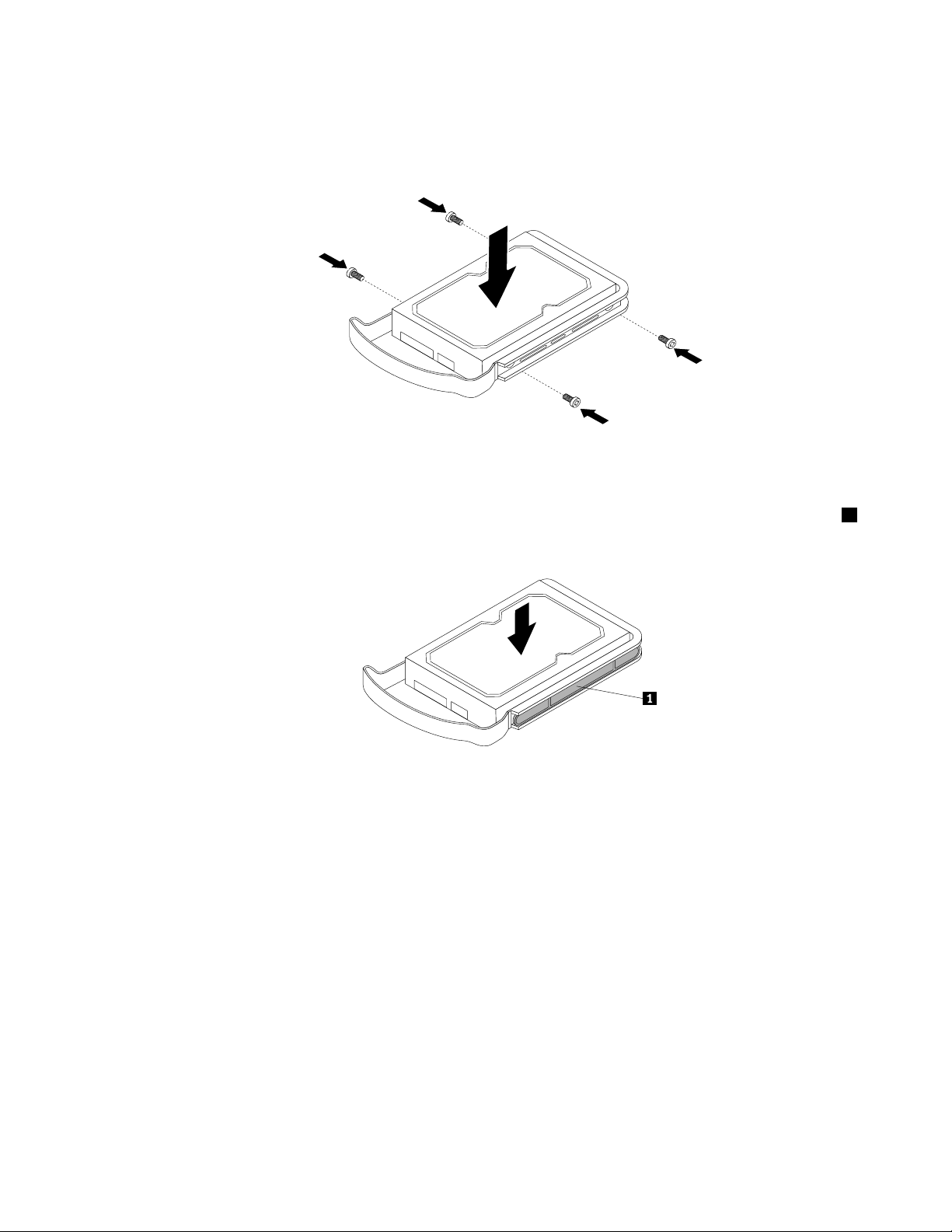
•Ifyouwanttosecuretheharddiskdriveinthebracketbyscrews,alignthescrewholesinbothsides
oftheharddiskdrivewiththecorrespondingholesinthebracket.Then,installthefourscrewsto
securetheharddiskdriveinthebracket.
Figure41.Securingtheharddiskdriveinthebracketbyscrews
•Ifyouwanttosecuretheharddiskdriveinthebracketbyretainers,aligntheholesinbothsidesof
theharddiskdrivewiththecorrespondingholesinthebracket.Then,carefullyinstalltheretainers1
onbothsidestosecuretheharddiskdriveinthebracket.
Figure42.Securingtheharddiskdriveinthebracketbyretainers
Chapter5.ReplacingFRUs71
Page 78

7.Pushtheharddiskdrivetoslidethebracketwiththeharddiskdriveintothedrivebayuntilitsnaps
intoposition.
Figure43.Slidingthenon-hot-swapharddiskdriveintothebay
8.Locateanavailableve-wirepowerconnectorandanavailablesignalcableconnector.Then,connect
thepowercableandthesignalcabletotheharddiskdrive.
9.T ocompletetheinstallation,goto“Completingthepartsreplacement”onpage122.Then,youmight
needtochecktheharddiskdrivestatusLEDstomakesurethattheharddiskdriveisoperating
correctly.Restarttheserverforthenewlyinstalleddrivetoberecognized.Iftheamberharddiskdrive
statusLEDislitcontinuously,thisindicatesthattheharddiskdriveisfaultyandmustbereplaced;ifthe
greenharddiskdrivestatusLEDisblinking,thisindicatesthattheharddiskdriveisoperatingcorrectly.
Note:IftheserverisconguredforRAIDoperationusingaRAIDcontroller,youmighthaveto
recongurethediskarraysafteryoureplaceharddiskdrives.
InstallingorremovingaPCIcard
ThissectionprovidesinstructionsonhowtoinstallorremoveaPCIcard.
TheEMIintegrityandcoolingoftheserverareprotectedbyhavingalldrivebaysandPCIcardslotscovered
oroccupied.WhenyouinstalladriveorPCIcard,savetheEMCshieldordrivebayllerfromthedrivebay
orsavethePCIcardslotcoverintheeventthatyoulaterremovethedevice.Anunoccupieddrivebayor
PCIcardslotwithoutcover,shield,ller,oranyotherprotectionmightimpacttheEMIintegrityandcooling
oftheserver,whichmightresultinoverheatingorcomponentdamage.
Note:ThePCIcardsareextremelysensitivetoelectrostaticdischarge.Makesurethatyoureadand
understand“Handlingstatic-sensitivedevices”onpage40
rstandcarefullyperformtheoperation.
72ThinkServerTD230HardwareMaintenanceManual
Page 79

InstallingaPCIcard
Attention:
DonotopenyourserverorattemptanyrepairbeforereadingandunderstandingtheSafetyInformationandthe
WarrantyandSupportInformationontheThinkServerDocumentationDVDthatcamewithyourproduct,and
“Guidelines”onpage39
http://www.lenovo.com/support
ThissectionprovidesinstructionsonhowtoinstallaPCIcard.
ToinstallaPCIcard,dothefollowing:
Note:UseanydocumentationthatcamewiththePCIcardandfollowthoseinstructionsinadditionto
theinstructionsinthissection.
1.Removeallmediafromthedrivesandturnoffallattacheddevicesandtheserver.Then,disconnectall
powercordsfromelectricaloutletsanddisconnectallcablesthatareconnectedtotheserver.
2.Removetheservercover.See“Removingtheservercover”onpage43.
3.Laytheserveronitssideforeasieroperation.
4.LocateanappropriatePCIcardslotonthesystemboard.See“Locatingpartsonthesystemboard”
onpage33toidentifythetypesofPCIcardslotsforyourserver.
5.RemovethePCIcardslotbracketbyremovingthescrewthatsecuresthebracketandthenliftthe
bracketoutofthechassis.SavethePCIcardslotbracketintheeventthatyoulaterremovethePCI
cardandneedthebrackettocovertheplace.
6.T ouchthestatic-protectivepackagethatcontainsthenewPCIcardtoanyunpaintedsurfaceonthe
outsideoftheserver.Then,removethenewPCIcardfromthepackage.
.Toobtainacopyofthepublications,goto:
Note:CarefullyhandlethePCIcardbyitsedges.
Chapter5.ReplacingFRUs73
Page 80

7.PositionthenewPCIcardonthePCIcardslotwhichyouhaveremovedtheslotbracketinstep5on
page73.Then,pressthePCIcardstraightdownuntilitissecurelyseatedintotheslot.Installthe
screwtosecurethePCIcardinplace.
Figure44.InstallingaPCIcard
8.DependingonthetypeofthePCIcard,youmightneedtoconnectanyrequiredcablestothePCIcard.
9.T ocompletetheinstallation,goto“Completingthepartsreplacement”onpage122.
RemovingaPCIcard
Attention:
DonotopenyourserverorattemptanyrepairbeforereadingandunderstandingtheSafetyInformationandthe
WarrantyandSupportInformationontheThinkServerDocumentationDVDthatcamewithyourproduct,and
“Guidelines”onpage39.T oobtainacopyofthepublications,goto:
http://www.lenovo.com/support
ThissectionprovidesinstructionsonhowtoremoveaPCIcard.
ToremoveaPCIcard,dothefollowing:
Note:UseanydocumentationthatcamewiththePCIcardandfollowthoseinstructionsinadditionto
theinstructionsinthissection.
1.Removeallmediafromthedrivesandturnoffallattacheddevicesandtheserver.Then,disconnectall
powercordsfromelectricaloutletsanddisconnectallcablesthatareconnectedtotheserver.
74ThinkServerTD230HardwareMaintenanceManual
Page 81

2.Removetheservercover.See“Removingtheservercover”onpage43.
3.Laytheserveronitssideforeasieroperation.
4.LocatethePCIcardyouwanttoremove.Then,dependingonthetypeofthePCIcard,youmightneed
todisconnectanycablesfromthePCIcardorthesystemboard.
5.RemovethescrewthatsecuresthePCIcard.Then,graspthePCIcardbytheedgesandcarefullypullit
outofthePCIcardslot.Ifnecessary,alternatemovingeachsideofthePCIcardasmallandequal
amountuntilitiscompletelyremovedfromtheslot.
Figure45.RemovingaPCIcard
6.T ocompletetheremovalprocedure,goto“Completingthepartsreplacement”onpage122.
IfyouareinstructedtoreturntheremovedPCIcardtothemanufacturer,followallpackaginginstructions
anduseanypackagingmaterialsthataresuppliedtoyouforshipping.
InstallingorremovingtheEthernetcard
ThissectionprovidesinstructionsonhowtoinstallorremovetheEthernetcard.
InstallingtheEthernetcard
Attention:
DonotopenyourserverorattemptanyrepairbeforereadingandunderstandingtheSafetyInformationandthe
WarrantyandSupportInformationontheThinkServerDocumentationDVDthatcamewithyourproduct,and
“Guidelines”onpage39
http://www.lenovo.com/support
.Toobtainacopyofthepublications,goto:
Chapter5.ReplacingFRUs75
Page 82

ThissectionprovidesinstructionsonhowtoinstalltheEthernetcardandhowtoinstalltheEthernetcard
driveronWindowsoperatingsystems.UseanydocumentationthatcamewiththeEthernetcardandfollow
thoseinstructionsinadditiontotheinstructionsinthissection.
ToinstalltheEthernetcard,dothefollowing:
1.Removeallmediafromthedrivesandturnoffallattacheddevicesandtheserver.Then,disconnectall
powercordsfromelectricaloutletsanddisconnectallcablesthatareconnectedtotheserver.
2.Removetheservercover.See“Removingtheservercover”onpage43.
3.Laytheserveronitssideforeasieroperation.
4.T ouchthestatic-protectivepackagethatcontainstheEthernetcardtoanyunpaintedsurfaceonthe
outsideoftheserver.Then,removetheEthernetcardfromthepackage.
5.TheEthernetcardisakindofPCIcard.See“InstallingaPCIcard”onpage73andfollowthose
instructionstoinstalltheEthernetcard.
6.T ocompletetheinstallation,goto“Completingthepartsreplacement”onpage122.
OnLinuxoperatingsystems,youdonotneedtoinstallanydevicedriverfortheEthernetcard;onWindows
operatingsystems,youneedtoinstallthedevicedriverfortheEthernetcard.Toinstallthedevicedriver
onWindowsoperatingsystems,dothefollowing:
1.Saveanyopendocumentsandexitallapplications.
2.InserttheThinkServerEasyStartupDVDthatcamewithyourserverintotheDVDdrive.
Note:YoudonotneedtousethedriverdiscthatcamewiththeEthernetcard.
3.Right-clickMyComputerandselectProperties.TheSystemPropertieswindowopens.
4.OntheHardwaretab,clicktheDeviceManagerbutton.TheDeviceManagerwindowopens.
5.ExpandtheNetworkadaptersandthenright-clickoneoftheEthernetcards(PRO/1000PTorthe
yellowquestionmark).
6.SelectUpdateDriver....TheHardwareUpdateWizardprogramopens.
7.SelectInstallthesoftwareautomatically(Recommended)andclickNexttocontinue.
8.Followtheinstructionsonthescreen.
RemovingtheEthernetcard
Attention:
DonotopenyourserverorattemptanyrepairbeforereadingandunderstandingtheSafetyInformationandthe
WarrantyandSupportInformationontheThinkServerDocumentationDVDthatcamewithyourproduct,and
“Guidelines”onpage39
http://www.lenovo.com/support
ThissectionprovidesinstructionsonhowtoremovetheEthernetcard.Useanydocumentationthatcame
withtheEthernetcardandfollowthoseinstructionsinadditiontotheinstructionsinthissection.
ToremovetheEthernetcard,dothefollowing:
1.Removeallmediafromthedrivesandturnoffallattacheddevicesandtheserver.Then,disconnectall
powercordsfromelectricaloutletsanddisconnectallcablesthatareconnectedtotheserver.
2.Removetheservercover.See“Removingtheservercover”onpage43.
3.Laytheserveronitssideforeasieroperation.
4.TheEthernetcardisakindofPCIcard.See“RemovingaPCIcard”onpage74andfollowthose
instructionstoremovetheEthernetcard.
76ThinkServerTD230HardwareMaintenanceManual
.Toobtainacopyofthepublications,goto:
Page 83

5.IfyouareinstructedtoreturntheremovedEthernetcardtothemanufacturer,followallpackaging
instructionsanduseanypackagingmaterialsthataresuppliedtoyouforshipping.
6.T ocompletetheremovalprocedure,goto“Completingthepartsreplacement”onpage122.
InstallingorremovingtheThinkServerRAID100UpgradeKeyfor AdvancedRAID
ThissectionprovidesinstructionsonhowtoinstallorremovetheThinkServerRAID100UpgradeKeyfor
AdvancedRAID(hereaftercalledtheRAID5key).TheRAID5keyisanactivationkey,whichyoucaninstall
onthesystemboardtoenabletheRAID5congurationfunctionoftheonboardSATARAIDforyourserver.
InstallingtheRAID5key
Attention:
DonotopenyourserverorattemptanyrepairbeforereadingandunderstandingtheSafetyInformationandthe
WarrantyandSupportInformationontheThinkServerDocumentationDVDthatcamewithyourproduct,and
“Guidelines”onpage39
http://www.lenovo.com/support
ThissectionprovidesinstructionsonhowtoinstalltheRAID5key.
ToinstalltheRAID5key,dothefollowing:
Attention:Electrostaticdischarge(ESD)candamagetheRAID5key.Alwaysgroundyourselfandusea
groundstrapbeforetouchingtheoption.PerformthefollowingprocedureatanESD-safeworkstation.
1.Removeallmediafromthedrivesandturnoffallattacheddevicesandtheserver.Then,disconnectall
powercordsfromelectricaloutletsanddisconnectallcablesthatareconnectedtotheserver.
2.Removetheservercover.See“Removingtheservercover”onpage43.
3.Laytheserveronitssideforeasieroperation.
4.T ouchthestatic-protectivepackagethatcontainstheRAID5keytoanyunpaintedsurfaceonthe
outsideoftheserver.Then,removetheRAID5keyfromthepackage.
.Toobtainacopyofthepublications,goto:
Chapter5.ReplacingFRUs77
Page 84

5.LocatetheSATAkeyconnectoronthesystemboard.See“Locatingpartsonthesystemboard”on
page33.Then,installtheRAID5keyintotheSATAkeyconnector.
Figure46.InstallingtheRAID5key
Whattodonext:
•Toworkwithanotherpieceofhardware,gototheappropriatesection.
•Tocompletetheinstallation,goto“Completingthepartsreplacement”onpage122
.Then,referto
Chapter7“Conguringtheserver”onpage143forinformationaboutRAIDconguration.
RemovingtheRAID5key
Attention:
DonotopenyourserverorattemptanyrepairbeforereadingandunderstandingtheSafetyInformationandthe
WarrantyandSupportInformationontheThinkServerDocumentationDVDthatcamewithyourproduct,and
“Guidelines”onpage39
http://www.lenovo.com/support
ThissectionprovidesinstructionsonhowtoremovetheRAID5Keyfromthesystemboard.Ifyouremove
theRAID5KeyforAdvancedRAID,theRAID5congurationfunctionoftheonboardSATARAIDbecomes
unavailable.However,theRAID5congurationfunctionoftheThinkServerRAID500Adapterisstill
availableifyouhaveinstalledtheThinkServerRAID500UpgradeKeyforAdvancedRAIDontheadapter.
See“InstallingtheTR500key”onpage79
ToremovetheRAID5key,dothefollowing:
Attention:Electrostaticdischarge(ESD)candamagetheRAID5key.Alwaysgroundyourselfandusea
groundstrapbeforetouchingtheoption.PerformthefollowingprocedureatanESD-safeworkstation.
1.Removeallmediafromthedrivesandturnoffallattacheddevicesandtheserver.Then,disconnectall
powercordsfromelectricaloutletsanddisconnectallcablesthatareconnectedtotheserver.
2.Removetheservercover.See“Removingtheservercover”onpage43.
3.Laytheserveronitssideforeasieroperation.
.Toobtainacopyofthepublications,goto:
.
78ThinkServerTD230HardwareMaintenanceManual
Page 85

4.RemovetheRAID5keyfromtheSATAkeyconnectoronthesystemboard.See“Locatingpartsonthe
systemboard”onpage33.
Figure47.RemovingtheRAID5key
5.IfyouareinstructedtoreturntheremovedRAID5keytothemanufacturer,followallpackaging
instructionsanduseanypackagingmaterialsthataresuppliedtoyouforshipping.
Whattodonext:
•Toworkwithanotherpieceofhardware,gototheappropriatesection.
•Tocompletetheremovalprocedure,goto“Completingthepartsreplacement”onpage122.
InstallingorremovingtheThinkServerRAID500UpgradeKeyfor AdvancedRAID
ThissectionprovidesinstructionsonhowtoinstallorremovetheThinkServerRAID500UpgradeKeyfor
AdvancedRAID(hereaftercalledtheTR500key).IfyourserverhasaThinkServerRAID500Adapter
installedandyouwanttoenabletheRAID5congurationfunctionforthisadapter,youneedtoinstall
theTR500keyontheadapter.
InstallingtheTR500key
Attention:
DonotopenyourserverorattemptanyrepairbeforereadingandunderstandingtheSafetyInformationandthe
WarrantyandSupportInformationontheThinkServerDocumentationDVDthatcamewithyourproduct,and
“Guidelines”onpage39
http://www.lenovo.com/support
ThissectionprovidesinstructionsonhowtoinstalltheTR500key.
.Toobtainacopyofthepublications,goto:
ToinstalltheTR500key,dothefollowing:
Attention:Electrostaticdischarge(ESD)candamagetheTR500key.Alwaysgroundyourselfandusea
groundstrapbeforetouchingtheoption.PerformthefollowingprocedureatanESD-safeworkstation.
Chapter5.ReplacingFRUs79
Page 86

1.Removeallmediafromthedrivesandturnoffallattacheddevicesandtheserver.Then,disconnectall
powercordsfromelectricaloutletsanddisconnectallcablesthatareconnectedtotheserver.
2.Removetheservercover.See“Removingtheservercover”onpage43.
3.Laytheserveronitssideforeasieroperation.
4.T ouchthestatic-protectivepackagethatcontainstheTR500keytoanyunpaintedsurfaceonthe
outsideoftheserver.Then,removetheTR500keyfromthepackage.
5.InstalltheTR500keytotheThinkServerRAID500Adapter,asshown:
Figure48.InstallingtheTR500key
Whattodonext:
•Toworkwithanotherpieceofhardware,gototheappropriatesection.
•Tocompletetheinstallation,goto“Completingthepartsreplacement”onpage122.Then,referto
Chapter7“Conguringtheserver”onpage143forinformationaboutRAIDconguration.
RemovingtheTR500key
Attention:
DonotopenyourserverorattemptanyrepairbeforereadingandunderstandingtheSafetyInformationandthe
WarrantyandSupportInformationontheThinkServerDocumentationDVDthatcamewithyourproduct,and
“Guidelines”onpage39.T oobtainacopyofthepublications,goto:
http://www.lenovo.com/support
ThissectionprovidesinstructionsonhowtoremovetheTR500keyfromtheThinkServerRAID500Adapter.
IfyouremovetheTR500key,theRAID5congurationfunctionoftheThinkServerRAID500Adapter
becomesunavailable.However,theRAID5congurationfunctionoftheonboardSATARAIDisstillavailable
ifyouhaveinstalledtheRAID5Keyonthesystemboard.See“InstallingtheRAID5key”onpage77.
ToremovetheTR500key,dothefollowing:
Attention:Electrostaticdischarge(ESD)candamagetheTR500key.Alwaysgroundyourselfandusea
groundstrapbeforetouchingtheoption.PerformthefollowingprocedureatanESD-safeworkstation.
1.Removeallmediafromthedrivesandturnoffallattacheddevicesandtheserver.Then,disconnectall
powercordsfromelectricaloutletsanddisconnectallcablesthatareconnectedtotheserver.
2.Removetheservercover.See“Removingtheservercover”onpage43.
80ThinkServerTD230HardwareMaintenanceManual
Page 87

3.Laytheserveronitssideforeasieroperation.
4.RemovetheThinkServerRAID500Adapter.See“RemovingtheRAIDcard”onpage88andfollow
thoseinstructionstoremovetheThinkServerRAID500Adapter.
5.RemovetheTR500keyfromtheThinkServerRAID500Adapter.
Figure49.RemovingtheTR500key
6.IfyouareinstructedtoreturntheremovedTR500keytothemanufacturer,followallpackaging
instructionsanduseanypackagingmaterialsthataresuppliedtoyouforshipping.
Whattodonext:
•Toworkwithanotherpieceofhardware,gototheappropriatesection.
•Tocompletetheremovalprocedure,goto“Completingthepartsreplacement”onpage122.
InstallingorremovingtheThinkServerRemoteManagementModule3
ThissectionprovidesproductinformationabouttheThinkServerRemoteManagementModule3(hereafter
calledtheRMM3)andinstructionsonhowtoinstallorremovetheRMM3option.
Chapter5.ReplacingFRUs81
Page 88

AbouttheRMM3
TheRMM3isa1.23-inchx2.30-inchprintedcircuitboard.
Figure50.RMM3
TheRMM3isakindofadd-oncardwhichoffersconvenient,remoteKVM(keyboard,video,andmouse)
accessandcontrolthroughtheLANorInternet.Itcaptures,digitizes,andcompressesvideosandtransmits
thevideoswithkeyboardandmousesignalstoandfromaremotecomputer.Y oucanusetheRMM3to
gainlocation-independentremoteaccesstorespondtocriticalincidentsandtoundertakenecessary
maintenance.Inaddition,theRMM3offersintegratedremotepowermanagementusingintelligentplatform
managementinterface(IPMI).Therefore,workingasanintegratedsolutioninyourserver,theRMM3provides
anincreasedlevelofmanageabilityoverthebasicservermanagementavailabletothesystemboard.
TheRMM3optionpackagecontainsthefollowingitems:
•AThinkServerRemoteManagementModule3option
•Aplasticbagcontainingaslotbracket,aribboncable,threescrews,andthreeplasticstandoffs
InstallingtheRMM3
Attention:
DonotopenyourserverorattemptanyrepairbeforereadingandunderstandingtheSafetyInformationandthe
WarrantyandSupportInformationontheThinkServerDocumentationDVDthatcamewithyourproduct,and
“Guidelines”onpage39.T oobtainacopyofthepublications,goto:
http://www.lenovo.com/support
ThissectionprovidesinstructionsonhowtoinstalltheRMM3inyourserver.Y oucangetanincreasedlevel
ofmanageabilityoverthebasicservermanagementavailabletothesystemboardbyinstallingtheRMM3
option.See“AbouttheRMM3”onpage82
ToinstalltheRMM3,dothefollowing:
Attention:Electrostaticdischarge(ESD)candamagetheRMM3.Alwaysgroundyourselfanduseaground
strapbeforetouchingtheoption.PerformthefollowingprocedureatanESD-safeworkstation.
1.Removeallmediafromthedrivesandturnoffallattacheddevicesandtheserver.Then,disconnectall
powercordsfromelectricaloutletsanddisconnectallcablesthatareconnectedtotheserver.Wait
threetoveminutestolettheservercoolbeforeremovingtheservercover.
2.Removetheservercover.See“Removingtheservercover”onpage43.
3.Laytheserveronitssideforeasieroperation.
fortheproductinformation.
82ThinkServerTD230HardwareMaintenanceManual
Page 89

4.LocatetheRMM3connectoronthesystemboard.See“Locatingpartsonthesystemboard”on
page33.
5.RemovethecorrespondingPCIcardslotbracketbyremovingthescrewthatsecuresthebracket.
SavethePCIcardslotbracketintheeventthatyoulaterremovetheRMM3andneedthebracketto
covertheplace.
Note:Carefullyplacetheremovedscrewaside.YouwillneedthescrewwheninstallingtheRMM3.
Figure51.RemovingthePCIcardslotbracketfortheRMM3connector
6.T ouchthestatic-protectivepackagethatcontainstheRMM3toanyunpaintedsurfaceontheoutsideof
theserver.Then,removetheRMM3fromthepackage.
7.MakeanoteoftheMediaAccessController(MAC)addressoftheRMM3.Thisinformationisonalabel
attachedtotheRMM3andmightbeusedlaterforseveralsoftwarecongurations.Keepingarecordat
thismomentmighteliminatetheneedstoreopentheservercoverlater.
Chapter5.ReplacingFRUs83
Page 90

8.AttachtheRMM3totheslotbracketthatcamewiththeoptionpackagesothatthetwoscrewholesin
theslotbracketarealignedwiththecorrespondingholesintheRMM3.Then,installthetwoscrewsthat
camewiththeoptionpackagetosecuretheRMM3totheslotbracket.
Notes:
a.Therearethreescrewsintheoptionpackageandyouonlyneedtousetwoofthemtosecurethe
RMM3totheslotbracket.Theextraoneisabackupscrew.
b.Foreasieroperation,youmightneedtoattachaplasticstandoffthatcamewiththeoptionpackage
toeachscrewbeforeinstallingthescrew.
Figure52.InstallingtheRMM3ontheslotbracket
84ThinkServerTD230HardwareMaintenanceManual
Page 91

9.InserttheslotbracketwithRMM3intothepositionforthePCIcardslotbracketyouhaveremoved.
Then,securetheslotbracketwithRMM3inplacebyinstallingthescrewthatyouhaveremoved
instep5onpage83.
Figure53.InstallingtheslotbracketwithRMM3
Chapter5.ReplacingFRUs85
Page 92

10.Removetheribboncablefromtheoptionpackage.ConnectoneendoftheribboncabletotheRMM3
connectoronthesystemboard.See“Locatingpartsonthesystemboard”onpage33.Then,connect
theotherendoftheribboncabletotheconnectorontheRMM3.
Figure54.Connectingtheribboncable
Whattodonext:
•Toworkwithanotherpieceofhardware,gototheappropriatesection.
•Tocompletetheinstallation,goto“Completingthepartsreplacement”onpage122
.Afterinstallingthe
RMM3andrestartingtheserver,connectanetworkcabletotheRMM3networkinterfacecontroller,then
conguretheRMM3byreferringtotheThinkServerRemoteManagementUserGuideontheThinkServer
DocumentationDVDthatcamewithyourproduct.
RemovingtheRMM3
Attention:
DonotopenyourserverorattemptanyrepairbeforereadingandunderstandingtheSafetyInformationandthe
WarrantyandSupportInformationontheThinkServerDocumentationDVDthatcamewithyourproduct,and
“Guidelines”onpage39
http://www.lenovo.com/support
ThissectionprovidesinstructionsonhowtoremovetheRMM3.IfyouhaveinstalledaRMM3optioninyour
server,youcanperformthefollowingprocedurewhenyouwanttoremovethisoption.
86ThinkServerTD230HardwareMaintenanceManual
.Toobtainacopyofthepublications,goto:
Page 93
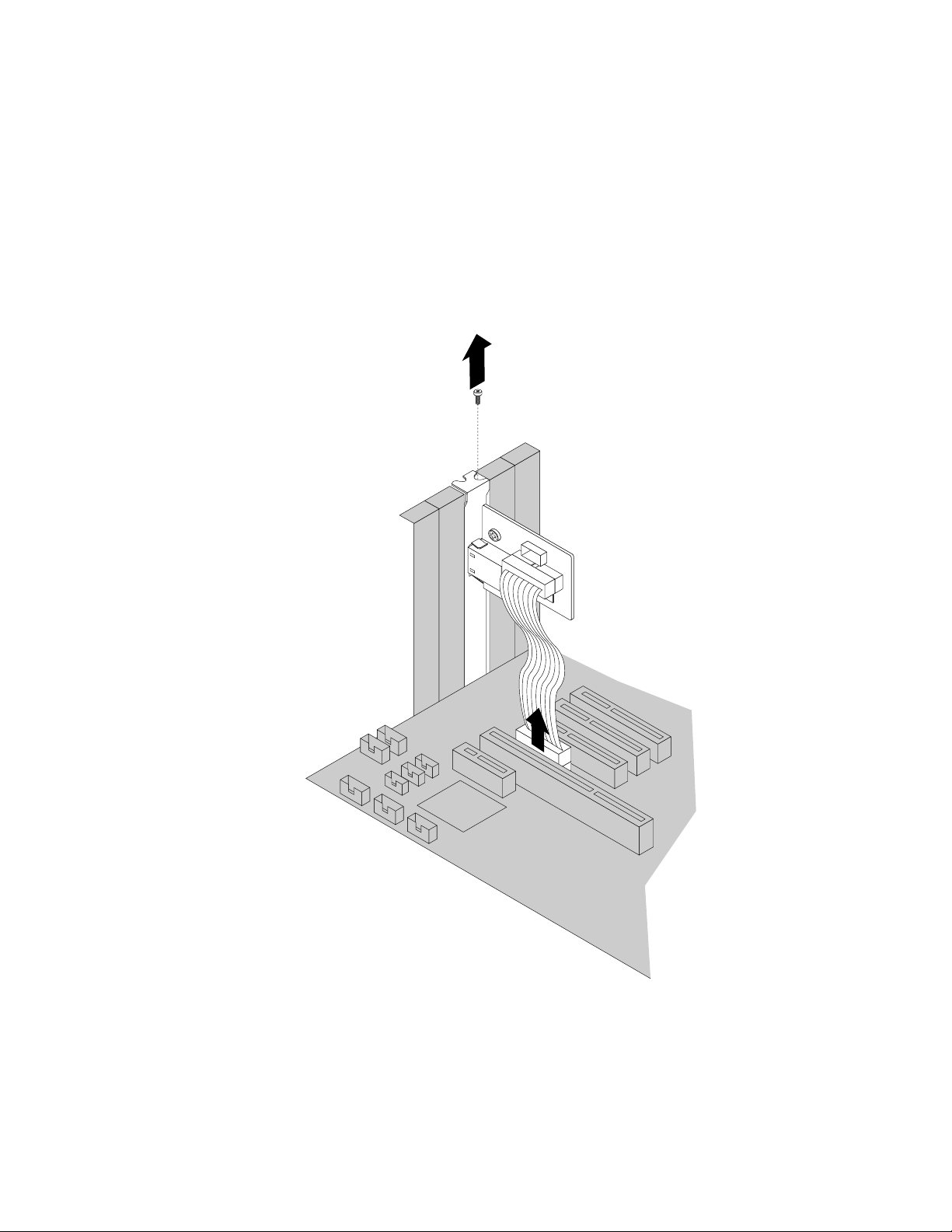
ToremovetheRMM3,dothefollowing:
1.Removeallmediafromthedrivesandturnoffallattacheddevicesandtheserver.Then,disconnectall
powercordsfromelectricaloutletsanddisconnectallcablesthatareconnectedtotheserver.Wait
threetoveminutestolettheservercoolbeforeremovingtheservercover.
2.Removetheservercover.See“Removingtheservercover”onpage43.
3.Laytheserveronitssideforeasieroperation.
4.LocatetheRMM3inyourserver.Then,disconnecttheribboncablefromtheRMM3connectoronthe
systemboard.See“Locatingpartsonthesystemboard”onpage33.Removethescrewthatsecures
theslotbracketwithRMM3.Then,carefullylifttheslotbracketwithRMM3outoftheserver.
Figure55.DisconnectingtheribboncableandremovingtheslotbracketwithRMM3
5.PuttheremovedRMM3kit(slotbracketwithRMM3andribboncable)intoitsoriginalpackage.If
necessary,disconnecttheribboncablefromtheRMM3.
6.IfyouareinstructedtoreturntheremovedRMM3kittothemanufacturer,followallpackaging
instructionsanduseanypackagingmaterialsthataresuppliedtoyouforshipping.
Chapter5.ReplacingFRUs87
Page 94

7.T ocompletetheremovalprocedure,goto“Completingthepartsreplacement”onpage122.
Installing,removing,orreplacinghardwaredevices
Thissectionprovidesinstructionsonhowtoinstall,remove,orreplacehardwaredevicesforyourserver.
Youcanmaintainyourserverbyreplacingthefailinghardwaredevices.Ifyouarereplacingahardware
device,performtheremovalprocedureandthenperformtheinstallationprocedureforthehardwaredevice
thatyouwanttoreplace.
RemovingorinstallingtheRAIDcard
ThissectionprovidesinstructionsonhowtoremoveorinstallthefollowingRAIDcards:
•ThinkServerRAID500Adapter(9240–8i)
•ThinkServer8708EM2RAIDAdapter
Note:Thissectiononlyappliestoservermodelswithhot-swapharddiskdrives.
RemovingtheRAIDcard
Attention:
DonotopenyourserverorattemptanyrepairbeforereadingandunderstandingtheSafetyInformationandthe
WarrantyandSupportInformationontheThinkServerDocumentationDVDthatcamewithyourproduct,and
“Guidelines”onpage39.T oobtainacopyofthepublications,goto:
http://www.lenovo.com/support
ThissectionprovidesinstructionsonhowtoremovetheRAIDcard.IfyouremovetheRAIDcard,you
cannotcongureRAIDusingtheRAIDcardandyouwilllooseallthecurrentRAIDcongurationbased
ontheRAIDcard.
Note:Thissectiononlyappliestoservermodelswithhot-swapharddiskdrives.
ToremovetheRAIDcard,dothefollowing:
1.Removeallmediafromthedrivesandturnoffallattacheddevicesandtheserver.Then,disconnectall
powercordsfromelectricaloutletsanddisconnectallcablesthatareconnectedtotheserver.
2.Removetheservercover.See“Removingtheservercover”onpage43.
3.Laytheserveronitssideforeasieroperation.
4.LocatetheRAIDcard.TheRAIDcardisinstalledintooneofthePCIExpressx8slotsonthesystem
board(callout31inFigure7“Locatingmajorpartsonthesystemboard”onpage34).See“Locating
partsonthesystemboard”onpage33.
5.RemoveanypartsanddisconnectanycablesthatmightpreventyouraccesstotheRAIDcard.
6.DisconnecttheminiSASsignalcablefromtheRAIDcard.
7.TheRAIDcardisakindofPCIcard.See“RemovingaPCIcard”onpage74andfollowthose
instructionstoremovetheRAIDcard.
8.IfyouareinstructedtoreturntheremovedRAIDcardtothemanufacturer,followallpackaging
instructionsanduseanypackagingmaterialsthataresuppliedtoyouforshipping.
Whattodonext:
•Toworkwithanotherpieceofhardware,gototheappropriatesection.
•Tocompletetheremovalprocedure,goto“Completingthepartsreplacement”onpage122
.
88ThinkServerTD230HardwareMaintenanceManual
Page 95

InstallingtheRAIDcard
Thissectionprovidesinstructionsonthefollowing:
•“InstallingtheThinkServerRAID500Adapter”onpage89
•“InstallingtheThinkServer8708EM2RAIDAdapter”onpage90
Note:Thissectiononlyappliestoservermodelswithhot-swapharddiskdrives.
InstallingtheThinkServerRAID500Adapter
Attention:
DonotopenyourserverorattemptanyrepairbeforereadingandunderstandingtheSafetyInformationandthe
WarrantyandSupportInformationontheThinkServerDocumentationDVDthatcamewithyourproduct,and
“Guidelines”onpage39
http://www.lenovo.com/support
ThissectionprovidesinstructionsonhowtoinstalltheRAIDcard.
Note:Thissectiononlyappliestoservermodelswithhot-swapharddiskdrives.
ToinstalltheRAIDcard,dothefollowing:
1.Removeallmediafromthedrivesandturnoffallattacheddevicesandtheserver.Then,disconnectall
powercordsfromelectricaloutletsanddisconnectallcablesthatareconnectedtotheserver.
2.Removetheservercover.See“Removingtheservercover”onpage43.
3.Laytheserveronitssideforeasieroperation.
4.TheRAIDcardshouldbeinstalledintotheappropriatePCIExpressx8slotonthesystemboard(callout
31inFigure7“Locatingmajorpartsonthesystemboard”onpage34).
5.T ouchthestatic-protectivepackagethatcontainstheRAIDcardtoanyunpaintedsurfaceonthe
outsideoftheserver.Then,removetheRAIDcardfromthepackage.
6.DependingonyourRAIDcard,youmightneedtoinstalltheTR500keyontheRAIDcard.See“Installing
theTR500key”onpage79andfollowthoseinstructionstoinstalltheTR500key.
7.ConnecttheminiSASsignalcabletotheminiSASsignalcableconnector0ontheRAIDcard.See
Figure56“ConnectingtheminiSASsignalcables”onpage90.
.Toobtainacopyofthepublications,goto:
Note:TheminiSASsignalcablelengthis880mm(34.65inches).
8.TheRAIDcardisakindofPCIcard.See“InstallingaPCIcard”onpage73andfollowthoseinstructions
toinstalltheRAIDcard.T akecautionwhenhandlingtheminiSASsignalcabletoavoiddamaging
theminiSASsignalcableconnector.
Chapter5.ReplacingFRUs89
Page 96

9.ConnecttheminiSASsignalcables(port0toport3)tothecorrespondingSATA/SASsignalconnectors
(connector0toconnector3)onthehot-swapharddiskdrivebackplanes.See“Locatingconnectorson
thehot-swapharddiskdrivebackplanes”onpage37.
Note:EachminiSASsignalcablemighthavealabelattached.Thenumberonthelabelindicates
theportnumber.
Figure56.ConnectingtheminiSASsignalcables
1MiniSASsignalcableconnector04MiniSASsignalcable-port1
2MiniSASsignalcableconnector15MiniSASsignalcable-port2
3MiniSASsignalcable-port06MiniSASsignalcable-port3
Whattodonext:
•Toworkwithanotherpieceofhardware,gototheappropriatesection.
•Tocompletetheinstallation,goto“Completingthepartsreplacement”onpage122.Then,referto
Chapter7“Conguringtheserver”onpage143forinformationaboutRAIDconguration.
InstallingtheThinkServer8708EM2RAIDAdapter
Attention:
DonotopenyourserverorattemptanyrepairbeforereadingandunderstandingtheSafetyInformationandthe
WarrantyandSupportInformationontheThinkServerDocumentationDVDthatcamewithyourproduct,and
“Guidelines”onpage39
http://www.lenovo.com/support
.Toobtainacopyofthepublications,goto:
ThissectionprovidesinstructionsonhowtoinstalltheRAIDcard.
Note:Thissectiononlyappliestoservermodelswithhot-swapharddiskdrives.
ToinstalltheRAIDcard,dothefollowing:
90ThinkServerTD230HardwareMaintenanceManual
Page 97

1.Removeallmediafromthedrivesandturnoffallattacheddevicesandtheserver.Then,disconnectall
powercordsfromelectricaloutletsanddisconnectallcablesthatareconnectedtotheserver.
2.Removetheservercover.See“Removingtheservercover”onpage43.
3.Laytheserveronitssideforeasieroperation.
4.TheRAIDcardshouldbeinstalledintotheappropriatePCIExpressx8slotonthesystemboard(callout
31inFigure7“Locatingmajorpartsonthesystemboard”onpage34).
5.T ouchthestatic-protectivepackagethatcontainstheRAIDcardtoanyunpaintedsurfaceonthe
outsideoftheserver.Then,removetheRAIDcardfromthepackage.
6.DependingonyourRAIDcard,youmightneedtoinstalltheThinkServer8708EM2RAIDBattery.See
“InstallingtheThinkServer8708EM2RAIDBattery”onpage92andfollowthoseinstructionstoinstall
thebatterycardassembly.
7.ConnecttheminiSASsignalcabletotheminiSASsignalcableconnector0ontheRAIDcard.See
Figure57“ConnectingtheminiSASsignalcables”onpage91
.
Note:TheminiSASsignalcablelengthis880mm(34.65inches).
8.TheRAIDcardisakindofPCIcard.See“InstallingaPCIcard”onpage73andfollowthoseinstructions
toinstalltheRAIDcard.T akecautionwhenhandlingtheminiSASsignalcabletoavoiddamaging
theminiSASsignalcableconnector.
9.ConnecttheminiSASsignalcables(port0toport3)tothecorrespondingSATA/SASsignalconnectors
(connector0toconnector3)onthehot-swapharddiskdrivebackplanes.See“Locatingconnectorson
thehot-swapharddiskdrivebackplanes”onpage37.
Note:EachminiSASsignalcablemighthavealabelattached.Thenumberonthelabelindicates
theportnumber.
Figure57.ConnectingtheminiSASsignalcables
1MiniSASsignalcableconnector4–74MiniSASsignalcable-port1
2MiniSASsignalcableconnector0–35MiniSASsignalcable-port2
3MiniSASsignalcable-port06MiniSASsignalcable-port3
Chapter5.ReplacingFRUs91
Page 98

Whattodonext:
•Toworkwithanotherpieceofhardware,gototheappropriatesection.
•Tocompletetheinstallation,goto“Completingthepartsreplacement”onpage122.Then,referto
Chapter7“Conguringtheserver”onpage143forinformationaboutRAIDconguration.
InstallingtheThinkServer8708EM2RAIDBattery
ThistopicprovidesinformationaboutinstallingtheThinkServer8708EM2RAIDBattery(hereafterreferredto
asthebatterycardassembly)ontheRAIDcard.ThebatterycardassemblymountsdirectlytotheRAIDcard
throughasmallboard-to-boardconnector(daughtercard).
Notes:
1.ThebatterycardassemblyprotectstheintegrityofthecacheddataontheRAIDcontrollerbyproviding
backuppowerupto72hoursinthecaseofacompleteacpowerfailureorabriefpoweroutage.It
hasbuilt-infunctionalitytochargethebatterypackautomaticallyandtocommunicatebatterystatus
informationsuchasvoltage,temperature,andcurrenttoyourserver.Italsoprovidesaninexpensive
alternativetousinganuninterruptiblepowersupply,andasecondleveloffaulttolerancewhenused
inconjunctionwithanuninterruptiblepowersupply.Formoreinformationaboutthebatterycard
assembly,seeAppendixA“RAIDbatterycardassembly”onpage161
.
2.Thebatterycardassemblyoptionkitcontainsauserguide,thebatterycardassembly,andthree
Phillips-headscrews.Donotremovethebatterycardassemblyfromtheantistaticshippingcontainer
untilyouarereadytoinstallit.Whenyouremovethebatterycardassemblyfromyourserver,placeitin
itsoriginalcontainer.
3.ChecktheappropriatesupportWebsitesforthelatestupdatesforyourbasicinput/outputsystem
(BIOS)code,utilityprograms,devicedrivers,andothersoftwareapplications.Followtheinstructions
providedbyyourServiceProvidertodownloadandinstallupdates.
4.Itisrecommendedthatyoureplacethebatterypackonthebatterycardassemblyannuallyorafter
500rechargingcycles,whichevercomesrst.
5.Thetemperatureofthebatterycardassemblyisgenerally15-20°C(59-68°F)higherthantheambient
temperatureduringfastcharge.Therefore,tocompleteafastchargecycle,theambienttemperature
shouldbelowerthan45°C(113°F).Iftheambienttemperatureexceeds45°C(113°F),thefastcharge
cyclewillterminateprematurely,thuspreventingthebatterycardassemblyfromreachingafully
chargedstate.
Attention:
•WhenattachingthebatterycardassemblytoaPCIExpressslot,centerthePhillips-headscrewdriverto
avoiddamagingthescrewheadanddonotover-tightenthescrewsasyoumightdamagethebattery
cardassembly.
•Thebatteryinthebatterycardassemblymustrechargeforatleastsixhoursduringfastchargeunder
normaloperatingconditions.
ToinstallthebatterycardassemblyontotheRAIDcard,dothefollowing:
92ThinkServerTD230HardwareMaintenanceManual
Page 99

1.Notethetopviewandbottomviewofthebatterycardassembly.Then,insertthebatterypackharness
connectorintotheJ4batterypackharnessconnectoronthebacksideofthebatterycardassembly.For
moreinformation,refertothefollowingillustrations.
Figure58.T opviewofthebatterycardassembly
1Batterypackharness
Figure59.Bottomviewofthebatterycardassembly
1J4batterypackharnessconnector
2J5board-to-boardconnector
3J2connector
2.Withthefrontsideup,placetheRAIDcardonaat,clean,static-freesurface.
Chapter5.ReplacingFRUs93
Page 100

3.HoldthebatterycardassemblywiththebatterysideupandtheJ5board-to-boardconnectorlining
upwiththeJ10BBUconnector1ontheRAIDcard.Carefullypressthebatterycardassemblyonto
theRAIDcardsothatthetwoconnectorsarermlyjoined.Then,securethebatterycardassembly
totheRAIDcardwiththethreescrewsandthestandoffsthatcomewiththebatterycardassembly
accessorykit.
Figure60.InstallingthebatterycardassemblyontotheRAIDcard
1J10BBUconnector
ConnectingtheminiSAScable
ThistopicprovidesinstructionsonhowtoconnecttheminiSASsignalcabletotheRAIDcardandthe
hot-swapharddiskdrivebackplanes.
Yourservercomeswithan880mm(34.65inches)miniSAScablewithfourminiSASconnectors.Thefour
SASconnectorsofthecableconnecttothefourSASconnectorsonthehot-swapharddiskdrivebackplanes.
94ThinkServerTD230HardwareMaintenanceManual
 Loading...