

Page 1

ThinkServerTD230
InstallationandUserGuide
MachineTypes:1027,1029,1039,and1040
Page 2

Note:
Beforeusingthisinformationandtheproductitsupports,besuretoreadandunderstandthefollowing:
•TheImportantNoticesthatcamewithyourproduct
•TheSafetyInformationandtheWarrantyandSupportInformationontheThinkServerDocumentationDVD
thatcamewithyourproduct
•AppendixB“Notices”onpage127
FourthEdition(August2013)
©CopyrightLenovo2010,2013.
LIMITEDANDRESTRICTEDRIGHTSNOTICE:IfdataorsoftwareisdeliveredpursuantaGeneralServicesAdministration
“GSA”contract,use,reproduction,ordisclosureissubjecttorestrictionssetforthinContractNo.GS-35F-05925.
Page 3

Contents
Safetyinformation..........iii
Chapter1.Generalinformation.....1
Introduction.................1
Noticesandstatementsinthedocument.....1
Relateddocumentation............2
Chapter2.Serversetuproadmap...3
Chapter3.Productoverview......5
Whatisincludedwithyourserver........5
Featuresandspecications...........5
Softwareprograms..............6
EasyStartup...............6
EasyManage...............6
Reliability,availability,andserviceability......7
Chapter4.Locatingparts,controls,
LEDs,andconnectors.........9
Frontview.................9
Rearview.................12
Hot-swapharddiskdrivestatusLEDs.....13
LEDsfortheEthernetconnectors.......13
Locatingservercomponents.........14
Locatingpartsonthesystemboard......15
LocatingdiagnosticLEDsonthesystemboard..16
Jumperblocksettings............17
Locatingconnectorsonthehot-swapharddisk
drivebackplanes..............18
Chapter5.Installing,removing,or
replacinghardware..........21
Guidelines................21
Basicguidelines............21
Systemreliabilityguidelines........22
Handlingstatic-sensitivedevices.....22
Workinginsidetheserverwiththepoweron.23
Removingtheservercover..........23
Removingandreinstallingthefrontbezel....25
Lockingorunlockingtheharddiskdriveside
door...................26
Installing,removing,orreplacingoptionalhardware
devices.................29
Installingorremovingamemorymodule...29
Removingorinstallinginternaldrives....32
InstallingorremovingaPCIcard......53
InstallingorremovingtheEthernetcard...56
InstallingorremovingtheThinkServerTD230
SATARAID5Upgrade..........58
InstallingorremovingtheThinkServer9240-8i
RAID5UpgradeKey..........60
InstallingorremovingtheThinkServerRemote
ManagementModule3.........62
Installing,removing,orreplacinghardware
devices.................69
RemovingorinstallingtheThinkServer9240-8i
RAID0/1Adapter............69
Removingorinstallingtheheatsinkandfan
assembly...............71
Removingorinstallingafrontfan.....77
Removingorinstallingtherearfan.....82
Removingorinstallingthemicroprocessor..86
Replacingthesystemboardbattery....89
Completingthepartsreplacement.......90
Installingtheservercover........91
Connectingthecables..........91
Turningontheserver..........91
Updatingtheserverconguration.....91
Turningofftheserver..........92
Connectingexternaldevices.......92
Chapter6.Conguringtheserver..95
UsingtheSetupUtilityprogram........95
StartingtheSetupUtilityprogram.....95
IntroductionoftheBIOSitems.......96
Usingpasswords............101
RAIDcontrollers..............102
UsingtheThinkServerEasyStartupprogram...103
BeforeyouusetheEasyStartupDVD....104
Setupandconguration.........104
ConguringRAID............105
Typicaloperatingsysteminstallation....105
ConguringtheonboardSATAsoftwareRAID..105
RAIDinformation............105
StartingtheIntelEmbeddedServerRAID
TechnologyIIprogram..........106
CreatingaRAIDvolume.........106
InitializingtheRAIDvolume........107
DeletingtheRAIDvolume........107
RebuildingtheRAIDvolume.......108
CheckingtheRAID1volumeconsistency..108
ConguringtheGigabitEthernetcontroller....108
Updatingthermware............108
UsingtheEasyUpdateFirmwareUpdater
program...............109
©CopyrightLenovo2010,2013
i
Page 4

InstallingtheThinkServerEasyManage
program.................109
Chapter7.T roubleshooting.....111
Troubleshootingtables...........111
DVDdriveproblems...........111
Generalproblems............112
Harddiskdriveproblems.........112
Intermittentproblems..........112
Keyboard,mouse,orpointing-device
problems...............113
Memoryproblems...........113
Microprocessorproblems........114
Monitorproblems............115
Optional-deviceproblems........116
Powerproblems............117
Serialportproblems...........118
Softwareproblems...........119
UniversalSerialBus(USB)portproblems..119
Solvingpowerproblems...........119
SolvingEthernetcontrollerproblems......120
Solvingundeterminedproblems........120
Eventlogs................121
Systemeventlog..............121
Diagnosticprogramsandmessages......121
DiagnosticLEDsonthefrontpanelandthesystem
board..................122
AppendixA.Gettinghelpand
technicalassistance........123
Beforeyoucall...............123
Usingthedocumentation..........123
GettinghelpandinformationfromtheWorldWide
Web...................123
LenovoSupportWebsite..........124
Callingforservice.............124
Usingotherservices............125
Purchasingadditionalservices........125
LenovoproductserviceinformationforTaiwan..125
AppendixB.Notices.........127
Trademarks................128
Importantnotes..............128
Productrecyclinganddisposal........128
Particulatecontamination..........129
Turkishstatementofcompliance.......130
Batteryreturnprogram...........130
GermanOrdinanceforWorkglossstatement...132
Electronicemissionnotices..........132
FederalCommunicationsCommission(FCC)
Statement...............132
Index.................135
iiThinkServerTD230InstallationandUserGuide
Page 5
Safetyinformation
Beforeinstallingthisproduct,readtheSafetyInformation.
©CopyrightLenovo2010,2013
iii
Page 6
Important:Eachcautionanddangerstatementinthisdocumentislabeledwithanumber.Thisnumber
isusedtocrossreferenceanEnglish-languagecautionordangerstatementwithtranslatedversionsof
thecautionordangerstatementintheSafetyInformationmanual.Forexample,ifacautionstatementis
labeled“Statement1,”translationsforthiscautionstatementareintheSafetyInformationmanualunder
“Statement1.”
Besuretoreadandunderstandallcautionanddangerstatementsinthisdocumentbeforeyouperform
theprocedures.Readandunderstandanyadditionalsafetyinformationthatcomeswiththeserveroran
optionaldevicebeforeyouinstall,remove,orreplacethedevice.
Statement1
DANGER
Electricalcurrentfrompower,telephone,andcommunicationcablesishazardous.
Toavoidashockhazard:
•Donotconnectordisconnectanycablesorperforminstallation,maintenance,orrecongurationofthis
productduringanelectricalstorm.
•Connectallpowercordstoaproperlywiredandgroundedelectricaloutlet.
•Connecttoproperlywiredoutletsanyequipmentthatwillbeattachedtothisproduct.
•Whenpossible,useonehandonlytoconnectordisconnectsignalcables.
•Neverturnonanyequipmentwhenthereisevidenceofre,water ,orstructuraldamage.
•Disconnecttheattachedpowercords,telecommunicationssystems,networks,andmodemsbeforeyou
openthedevicecovers,unlessinstructedotherwiseintheinstallationandcongurationprocedures.
•Connectanddisconnectcablesasdescribedinthefollowingtablewheninstalling,moving,oropening
coversonthisproductorattacheddevices.
ToConnect:ToDisconnect:
1.TurneverythingOFF.
2.First,attachallcablestodevices.
3.Attachsignalcablestoconnectors.
4.Attachpowercordstooutlet.
5.TurndeviceON.
ivThinkServerTD230InstallationandUserGuide
1.TurneverythingOFF.
2.First,removepowercordsfromoutlet.
3.Removesignalcablesfromconnectors.
4.Removeallcablesfromdevices.
Page 7
Statement2
CAUTION:
Whenreplacingthelithiumbattery,useonlythebatteryrecommendedbythemanufacturer.Ifyour
systemhasamodulecontainingalithiumbattery,replaceitonlywiththesamemoduletypemadeby
thesamemanufacturer.Thebatterycontainslithiumandcanexplodeifnotproperlyused,handled,or
disposedof.Donot:
•Throworimmerseintowater
•Heattomorethan100°C(212°F)
•Repairordisassemble
Disposeofthebatteryasrequiredbylocalordinancesorregulations.
Statement3
CAUTION:
Whenlaserproducts(suchasCD-ROMs,DVDdrives,beropticdevices,ortransmitters)are
installed,notethefollowing:
•Donotremovethecovers.Removingthecoversofthelaserproductcouldresultinexposureto
hazardouslaserradiation.Therearenoserviceablepartsinsidethedevice.
•Useofcontrolsoradjustmentsorperformanceofproceduresotherthanthosespeciedherein
mightresultinhazardousradiationexposure.
DANGER
SomelaserproductscontainanembeddedClass3AorClass3Blaserdiode.Notethefollowing.
Laserradiationwhenopen.Donotstareintothebeam,donotviewdirectlywithoptical
instruments,andavoiddirectexposuretothebeam.
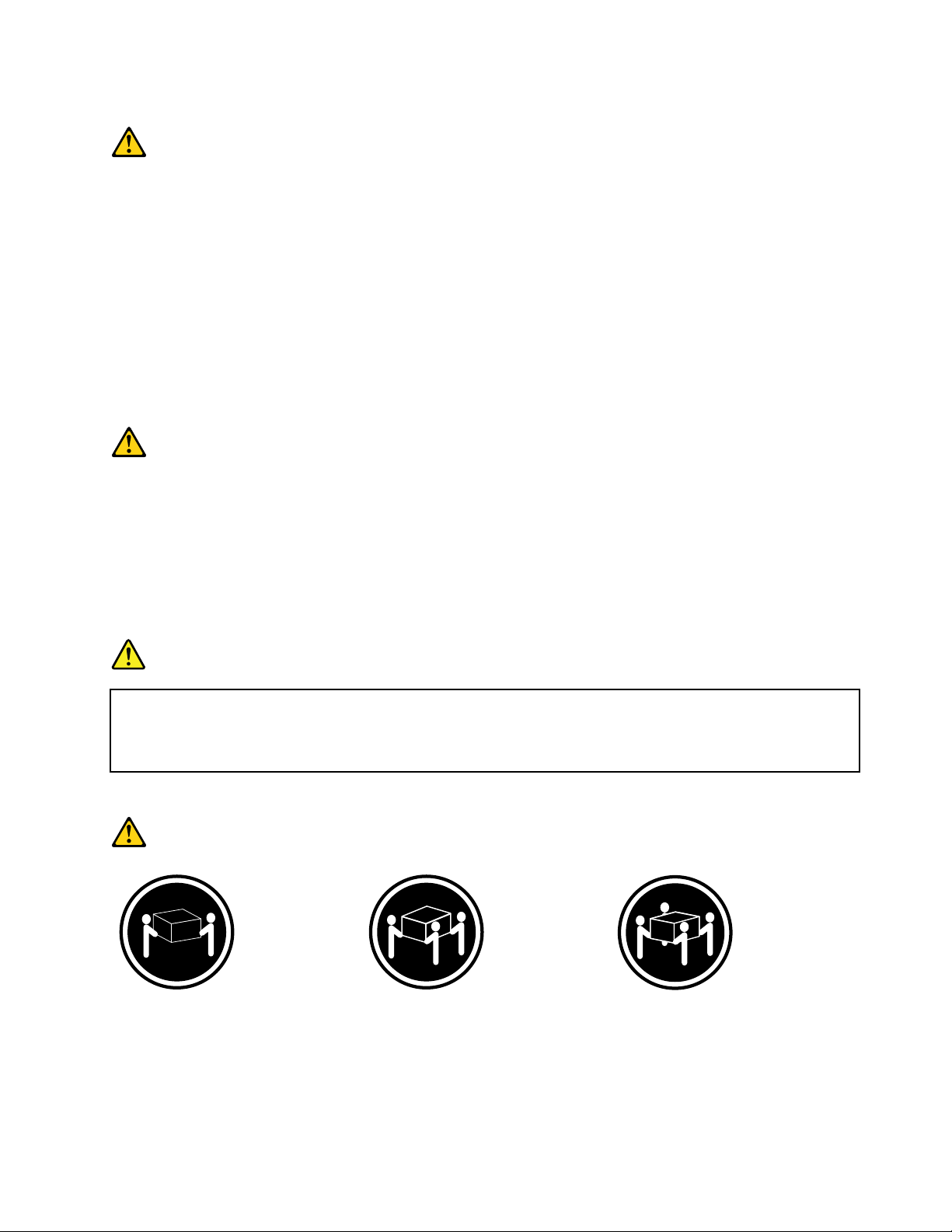
Statement4
≥18kg(39.7lb)≥32kg(70.5lb)≥55kg(121.2lb)
CAUTION:
Usesafepracticeswhenlifting.
©CopyrightLenovo2010,2013
v
Page 8
Statement5
CAUTION:
Thepowercontrolbuttononthedeviceandthepowerswitchonthepowersupplydonotturnoff
theelectricalcurrentsuppliedtothedevice.Thedevicealsomighthavemorethanonepower
cord.Toremoveallelectricalcurrentfromthedevice,ensurethatallpowercordsaredisconnected
fromthepowersource.
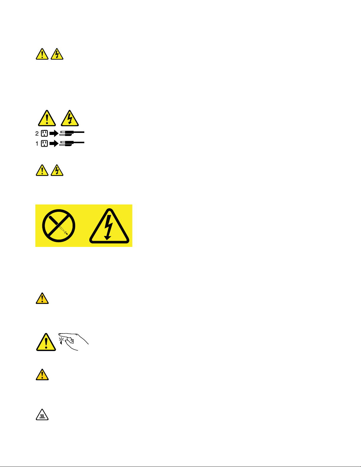
Statement8
CAUTION:
Neverremovethecoveronapowersupplyoranypartthathasthefollowinglabelattached.
Hazardousvoltage,current,andenergylevelsarepresentinsideanycomponentthathasthislabel
attached.Therearenoserviceablepartsinsidethesecomponents.Ifyoususpectaproblemwith
oneoftheseparts,contactaservicetechnician.
Statement11
CAUTION:
Thefollowinglabelindicatessharpedges,corners,orjointsnearby.
Statement12
CAUTION:
Thefollowinglabelindicatesahotsurfacenearby.
viThinkServerTD230InstallationandUserGuide
Page 9
Statement13
DANGER
Overloadingabranchcircuitispotentiallyarehazardandashockhazardundercertain
conditions.T oavoidthesehazards,ensurethatyoursystemelectricalrequirementsdonotexceed
branchcircuitprotectionrequirements.Refertotheinformationthatisprovidedwithyourdevice
forelectricalspecications.
Statement15
CAUTION:
Makesurethattherackissecuredproperlytoavoidtippingwhentheserverunitisextended.
Statement17
CAUTION:
Thefollowinglabelindicatesmovingpartsnearby.
Statement26
CAUTION:
Donotplaceanyobjectontopofrack-mounteddevices.
©CopyrightLenovo2010,2013
vii
Page 10

viiiThinkServerTD230InstallationandUserGuide
Page 11
Chapter1.Generalinformation
Thischapterprovidessomegeneralinformationaboutyourserver.
Thischaptercontainsthefollowingtopics:
•“Introduction”onpage1
•“Noticesandstatementsinthedocument”onpage1
•“Relateddocumentation”onpage2
Introduction
ThisInstallationandUserGuideisforyourLenovo®ThinkServer®TD230server(machinetypes1027,1029,
1039,and1040).Thisdocumentcontainsthefollowinginformation:
•Settingupandcablingtheserver
•Startingandconguringtheserver
•Installingoptionsandreplacingcustomerreplaceableunits(CRUs)
•Solvingproblems
TheservercomeswiththeThinkServerEasyStartupDVDtohelpyoucongurethehardware,installdevice
drivers,andinstalltheoperatingsystem.
Theservercomeswithalimitedwarranty.Forinformationaboutthetermsofthewarrantyandgetting
serviceandassistance,seetheWarrantyandSupportInformationontheThinkServerDocumentationDVD
thatcomeswithyourserver.
Toobtainthemostup-to-dateinformationabouttheserverandotherLenovoproducts,goto:
http://www.lenovo.com/thinkserver
Recordinformationabouttheserverinthefollowingtable.Youwillneedtheseinformationwhenyou
registertheserverwithLenovo.
Productname
Machinetype1027,1029,1039,or1040
Modelnumber
Serialnumber
Themodelnumberandserialnumberareonlabelsonthetoporonthebottomoftheserver.
ThinkServerTD230
_____________________________________________
_____________________________________________
Noticesandstatementsinthedocument
ThecautionanddangerstatementsthatappearinthisdocumentarealsointhemultilingualSafety
Information.Eachcautionanddangerstatementinthisdocumentislabeledwithanumber.Thisnumberis
usedtocrossreferenceanEnglish-languagecautionordangerstatementwithtranslatedversionsofthe
cautionordangerstatementintheSafetyInformation.See“Relateddocumentation”onpage2fordetailed
informationabouthowtogetthevariousdocumentationforyourserver.
©CopyrightLenovo2010,2013
1
Page 12
Thefollowingnoticesandstatementsareusedinthisdocument:
•Note:Thesenoticesprovideimportanttips,guidance,oradvice.
•Important:Thesenoticesprovideinformationoradvicethatmighthelpyouavoidproblemsor
inconvenientsituations.
•Attention:Thesenoticesindicatepotentialdamagetoprograms,devices,ordata.Anattentionnoticeis
placedjustbeforetheinstructionorsituationinwhichdamagecouldoccur.
•Caution:Thesestatementsindicatesituationsthatcanbepotentiallyhazardoustoyou.Acaution
statementisplacedjustbeforethedescriptionofapotentiallyhazardousproceduresteporsituation.
•Danger:Thesestatementsindicatesituationsthatcanbepotentiallylethalorextremelyhazardous
toyou.Adangerstatementisplacedjustbeforethedescriptionofapotentiallylethalorextremely
hazardousproceduresteporsituation.
Relateddocumentation
TheLenovoThinkServerDocumentationDVD,whichcomeswithyourserver,containsdocumentationforthe
serverinPortableDocumentFormat(PDF).ToviewthedocumentationontheThinkServerDocumentation
DVD,youneedtohavetheAdobeReader5.0programorlaterinstalled,orthexpdf,whichcomeswith
Linux®operatingsystems.
Thefollowingtableprovidesinformationaboutthegeneraldescriptionsofthevariousdocumentation
providedwithyourserverandhowtoobtainallthesedocumentation.
Table1.Relateddocumentationfortheserver
DocumentationDescriptionLocation
HardwareMaintenance
Manual
ImportantNotices
ReadMeFirst
SafetyInformation
WarrantyandSupport
Information
ThinkServerRemote
ManagementUserGuide
ThinkServerMegaRAID
SASSoftwareUserGuide
Note:Y oucanobtainallthedocumentationinPDFforyourserverfromtheLenovoSupportWebsiteat
http://www.lenovo.com/support.
Thisdocumentprovidesdiagnostic
information,partslisting,replacement
proceduresforallCRUs,andreplacement
proceduresforothereldreplaceableunits
(FRUs)replacedbytrainedservicepersonnel.
Thisdocumentincludessafetyandlegal
noticesthatyouareexpectedtoreadbefore
usingtheserver.
ThisdocumentdirectsyoutotheThinkServer
DocumentationDVDforcompletewarranty
andsupportinformation.
Thisdocumentincludestranslationsofall
safetystatementsusedintheThinkServer
documentation.
Thisdocumentincludesthewarranty
statementandinformationabouthowto
contactLenovoSupport.
IfyouhaveinstalledaThinkServerRemote
ManagementModule3intheserver,use
thisuserguidetohelpyoudotherelated
congurations.
IfyouhaveinstalledaThinkServer9240-8i
RAID0/1Adapterintheserver,usethisuser
guidetohelpyoucongureRAIDusingthe
ThinkServer9240-8iRAID0/1Adapter.
ThisdocumentisinEnglishandposted
ontheLenovoSupportWebsiteat
http://www.lenovo.com/support.
Thisdocumentisprintedoutand
providedinserverpackaging.
Thisdocumentisprintedoutand
providedinserverpackaging.
AvailableontheThinkServer
DocumentationDVD
AvailableontheThinkServer
DocumentationDVD
AvailableontheThinkServer
DocumentationDVD
AvailableontheThinkServer
DocumentationDVD
2ThinkServerTD230InstallationandUserGuide
Page 13

Chapter2.Serversetuproadmap
Thischapterprovidesageneralroadmaptoguideyouthroughsettingupyourserver.
Theserversetupprocedurevariesdependingonthecongurationoftheserverwhenitwasdelivered.In
somecases,theserverisfullyconguredandyoujustneedtoconnecttheservertothenetworkandan
electricaloutlet,andthenyoucanturnontheserver.Inothercases,theserverneedstohavehardware
featuresinstalled,requireshardwareandrmwareconguration,andrequirestheoperatingsystemto
beinstalled.
Table2.Serversetuproadmap
TaskWheretondtheinformation
Unpack“Whatisincludedwithyourserver”onpage5
Installhardware
ConnecttheEthernetcable
andpowercord
Turnontheservertoverify
operation
ReviewtheBIOSsettings
andcustomizeasneeded
CongureRAID
Checkforrmwareupdates
Installoperatingsystemand
basicdrivers
Installanyadditionaldrivers
neededforaddedfeatures
CongureEthernetsettings
intheoperatingsystem
Installremotemanagement
applications
Installapplications
Chapter5“Installing,removing,orreplacinghardware”onpage21
“Rearview”onpage12
“Turningontheserver”onpage91
“StartingtheSetupUtilityprogram”onpage95
“RAIDcontrollers”onpage102
“UsingtheEasyUpdateFirmwareUpdaterprogram”onpage109
“UsingtheThinkServerEasyStartupprogram”onpage103
Refertotheinstructionsthatcamewiththehardwareoption.
Seetheoperatingsystemhelp.Thisstepisnotrequirediftheoperatingsystemwas
installedusingtheThinkServerEasyStartupprogram.
“InstallingtheThinkServerEasyManageprogram”onpage109
Refertothedocumentationthatcomeswiththeapplicationsthatyouwanttoinstall.
©CopyrightLenovo2010,2013
3
Page 14

4ThinkServerTD230InstallationandUserGuide
Page 15
Chapter3.Productoverview
Thischapterprovidesinformationabouttheserverpackage,features,specications,andsoftwareprograms.
Whatisincludedwithyourserver
TheThinkServerTD230serverpackageincludestheserver,apowercord,documentation,theThinkServer
DocumentationDVD,andsoftwaremedia.
Featuresandspecications
Thefollowingtableprovidesinformationaboutthefeaturesandspecicationsoftheserver.Depending
ontheservermodel,somefeaturesmightnotbeavailable,orsomespecicationsmightnotapply.For
informationaboutyourspecicmodel,usetheSetupUtilityprogram.See“UsingtheSetupUtilityprogram”
onpage95
Table3.Featuresandspecications
.
Microprocessor(s):SupportsuptotwoIntel®Xeon®
dual-core,quad-core,orhex-coremicroprocessors
(internalcachesizevariesbymodeltype)Forthe
specictypeandspeedinformationaboutthe
microprocessor,usetheSetupUtilityprogram.
See“UsingtheSetupUtilityprogram”onpage
95
.Foralistofsupportedmicroprocessors,goto
http://www.lenovo.com/thinkserverandclickOptions
undertheProductstab.
Largesystem-memorycapacity:
•Supportsuptoeightmemorymodules
•Minimumsystemmemory:2GB
•Maximumsystemmemory:32GB(eachmemoryslot
withone4GBmemorymoduleinstalled)
•Memoryslots:Eightdualinlinememorymodule
(DIMM)slots
•Types:1333MHz,DDR3registeredSDRAMDIMMs
•Features:
–ErrorCheckingandCorrecting(ECC)
–Mirroring
–DemandScrubandPatrolScrub
•Supports2GBand4GBregisteredDIMMs
•NumbersofDIMMssupported:
–One,two,orfourDIMMsifonemicroprocessor
installed
–Two,four,six,oreightDIMMsiftwomicroprocessors
installed
Integratedvideocontroller:
anonboardhigh-performancegraphicscontroller
thatsupportshighresolutionsandincludesmany
performance-enhancingfeaturesfortheoperating-system
environment.
•64MBmemory,32MBforvideomemorycache
Theservercomeswith
Opticaldrive:
•SATADVD/RW
Harddiskdriveexpansionbays(dependingonmodel
type):
Supportsuptofour3.5-inchSerialAdvancedTechnology
Attachment(SATA)orSAShot-swapharddiskdrives
Supportsuptove3.5-inchSATAnon-hot-swaphard
diskdrives
Largedata-storagecapacityandhot-swapcapability
Someservermodelssupportuptofour3.5-inchhot-swap
harddiskdrives.Withthehot-swapfeature,youcanadd,
remove,orreplaceharddiskdriveswithoutturningoff
theserver.
Expansionslots(dependingonmodeltype):
•OnePeripheralComponentInterconnect(PCI)cardslot
•OnePCIExpressx4cardslot
•ThreePCIExpressx8cardslots
•Oneremotemanagementmodule3connector
Powersupply:
625-wattpowersupply
Systemfans:
•Twofrontsystemfans(systemfan2formicroprocessor
1areaandsystemfan1formicroprocessor2area)
•Onerearsystemfan
©CopyrightLenovo2010,2013
RAIDcontrollers:
5
Page 16
Table3.Featuresandspecications(continued)
Integratedfunctions:
•Ethernetcontrollers(Theservercomeswithtwo
integratedGigabitEthernetcontrollers,whichsupport
connectionto10Mbps,100Mbps,or1000Mbps
network.Formoreinformation,see“Conguringthe
GigabitEthernetcontroller”onpage108
•Oneserialport
•OneVideoGraphicsArray(VGA)monitorconnector
•SixUniversalSerialBus(USB)connectors(twofront
andfourrear)
•TwoRJ-45Ethernetconnectorsontherearpanel
•EightdiagnosticLEDs
IntelligentPlatformManagementInterface(IPMI)2.0
Thecommand-lineinterfaceprovidesdirectaccess
toservermanagementfunctionsthroughtheIPMI2.0
protocol.Usethecommand-lineinterfacetoissue
commandstocontroltheserverpower,viewsystem
information,andidentifytheserver.Y oucanalsosave
oneormorecommandsasatextleandruntheleasa
script.
ThinkServerRMM3SystemManagementCard
(Optional)
.)
TheserversupportstheonboardSATAsoftwareRAID
andaninstalledSASRAIDcard(ThinkServer9240-8i
RAID0/1Adapter),whicharerequiredforyoutousethe
hot-swapSATAorSASharddiskdrivesandtocreatethe
RAIDcongurations.
•OnboardICH10RSATAcontroller
•ThinkServer9240-8iRAID0/1Adapter
Size:
•Height:470mm(18.5inches)
•Width:210mm(8.27inches)
•Depth:510mm(20.1inches)
•Maximumweightwithpackage:26.2kg(57.76lb)
whenfullycongured
•Maximumweightwithoutpackage:22.3kg(49.2lb)
whenfullycongured
Electricalinput
•Inputvoltage:
–Lowrange:
Minimum:100Vac
Maximum:127Vac
Inputfrequencyrange:50to60Hz
–Highrange:
Minimum:200Vac
Maximum:240Vac
Inputfrequencyrange:50to60Hz
Softwareprograms
Lenovoprovidessoftwaretohelpgetyourserverupandrunning.
EasyStartup
TheThinkServerEasyStartupprogramsimpliestheprocessofconguringRAIDandinstallingsupported
Microsoft®Windows®andLinuxoperatingsystemsanddevicedriversonyourserver.TheEasyStartup
programisprovidedwithyourserverontheThinkServerEasyStartupDVD.TheDVDisself-starting(bootable).
TheuserguidefortheEasyStartupprogramisontheDVDandcanbeaccesseddirectlyfromtheprogram
interface.Foradditionalinformation,see“UsingtheThinkServerEasyStartupprogram”onpage103.
EasyManage
TheThinkServerEasyManageAgentenablesthisservertobemanagedbythecentralizedconsoleofan
EasyManageCoreServeroverthenetwork.TheThinkServerEasyManageAgentissupportedon32-bitand
64-bitWindows,RedHat,andSUSEoperatingsystems.
6ThinkServerTD230InstallationandUserGuide
Page 17

Reliability,availability,andserviceability
Reliability,availability,andserviceability(hereafterreferredtoasRAS)arethreeimportantserverdesign
features.TheRASfeatureshelpyoutoensuretheintegrityofthedatastoredontheserver,theavailabilityof
theserverwhenyouneedit,andtheeasewithwhichyoucandiagnoseandcorrectproblems.
TheserverhasthefollowingRASfeatures:
•AdvancedCongurationandPowerInterface(ACPI)
•AdvancedDesktopManagementInterface(DMI)
•Automaticmemorydownsizingonerrordetection
•Automaticrestartonnon-maskableinterrupt(NMI)
•Availabilityofmicrocodelevel
•Built-in,menu-drivensetup,systemconguration,andRAIDconguration
•Built-inmonitoringforfan,temperature,andvoltage
•Coolingfanswithspeed-sensingcapability
•ECCDDR3SDRAMwithSerialPresenceDetect(SPD)
•Errorcodesandmessagestohelpyouidentifyproblems
•Generatingerrorlogsforthepower-onself-test(POST)failures
•Hot-swapSASharddiskdrives
•IntegratedEthernetcontrollers
•IntelligentPlatformManagementInterface(IPMI)2.0
•Power-onself-test(POST)
•Standbyvoltageforsystem-managementfeaturesandmonitoring
•System-errorlight-emittingdiode(LED)onthefrontpanel
•Vitalproductdata(VPD),includingtheserialnumberinformationandreplacementpartnumbers,storedin
thenonvolatilememoryforeasierremotemaintenance
Chapter3.Productoverview7
Page 18

8ThinkServerTD230InstallationandUserGuide
Page 19
Chapter4.Locatingparts,controls,LEDs,andconnectors
Thischapterprovidesinformationtohelpyoulocateyourserverparts,controls,light-emittingdiodes
(LEDs),andconnectors.
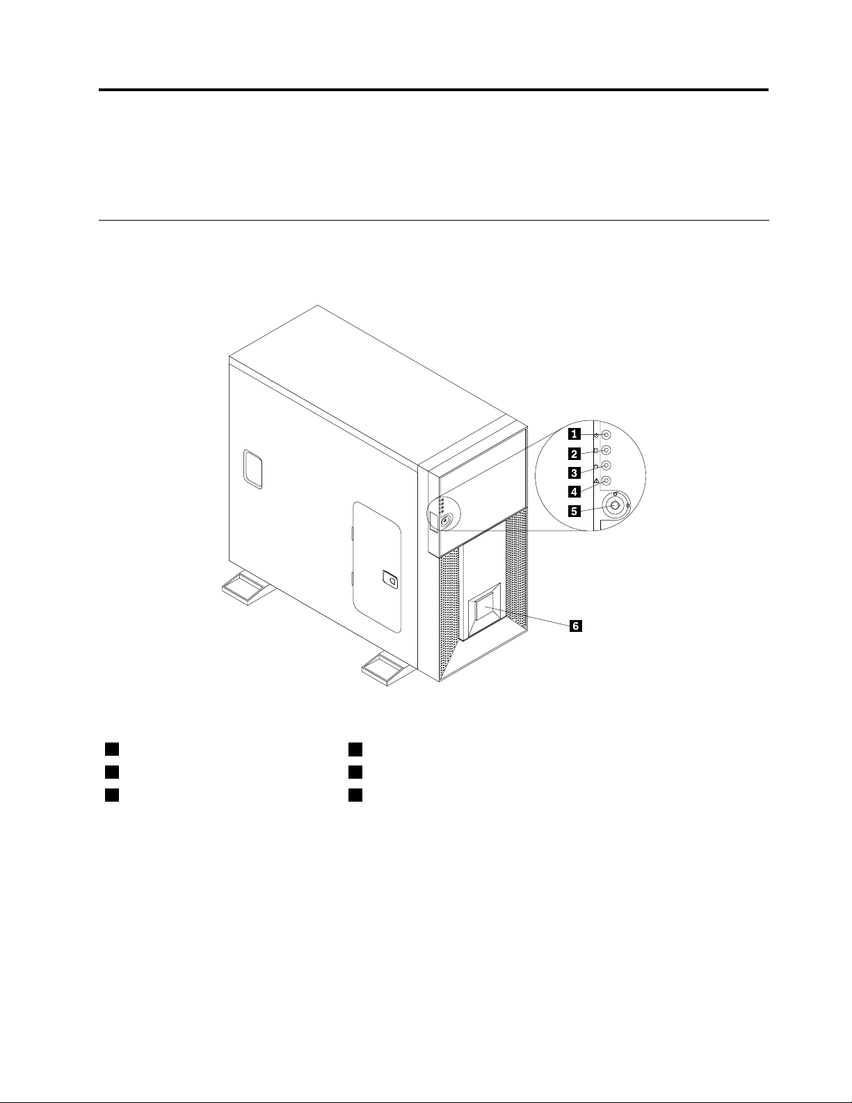
Frontview
Figure1“Frontviewoftheserver”onpage9showstheLEDsandpartsonthefrontoftheserver.
Figure1.Frontviewoftheserver
1PowerLED
2HarddiskdrivestatusLED5Frontdoorlock
3EthernetstatusLED6Logoplate
©CopyrightLenovo2010,2013
4SystemstatusLED
9
Page 20
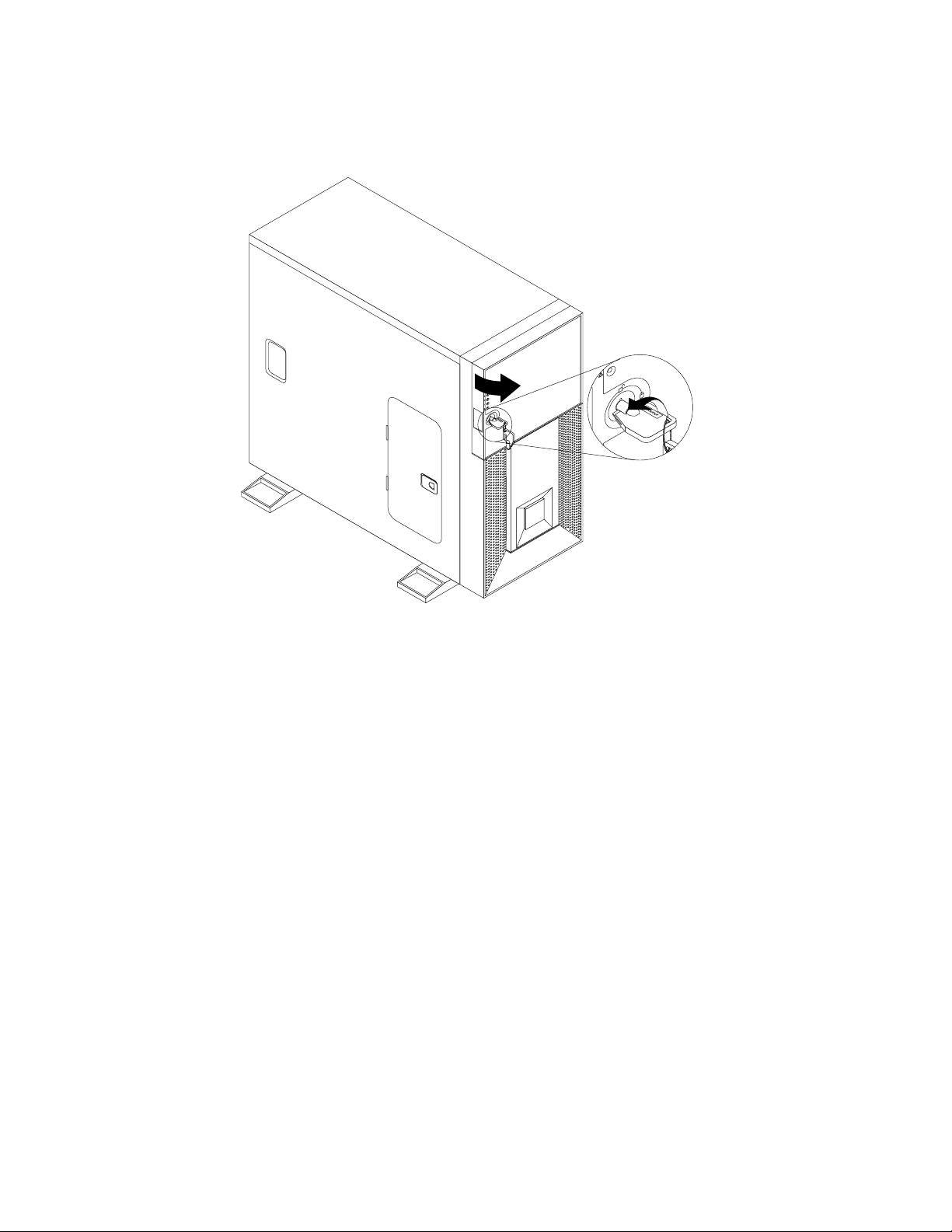
Youcanopenthefrontdoorwiththekeytolocatecontrols,LEDs,connectors,andotherpartsonthe
frontpanel.
Figure2.Openingthefrontdoor
10ThinkServerTD230InstallationandUserGuide
Page 21
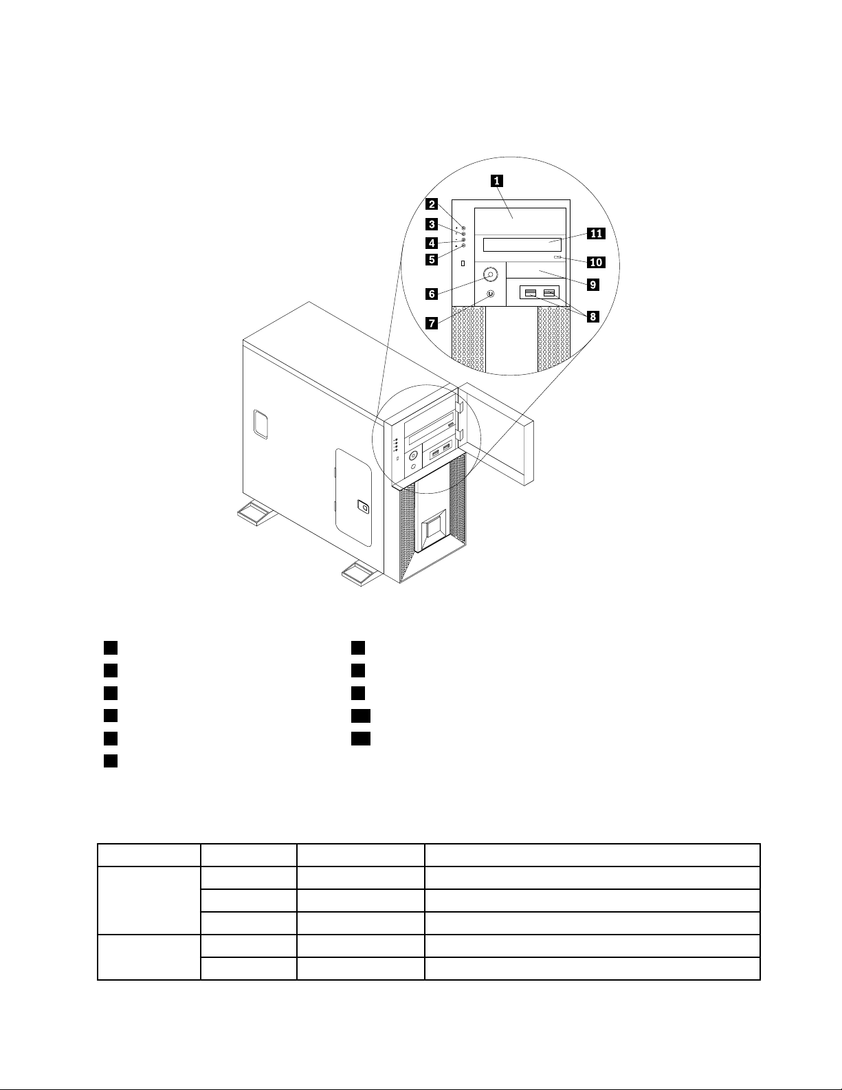
Figure3“Frontviewoftheserver(withthefrontdooropen)”onpage11showsthecontrols,LEDs,
connectors,andotherpartsonthefrontpanelafteryouopenthefrontdoor.
Figure3.Frontviewoftheserver(withthefrontdooropen)
15.25-inchdrivebay7Resetbutton
2PowerLED
3HarddiskdrivestatusLED93.5-inchdrivebay
4EthernetstatusLED
5SystemstatusLED11Opticaldrive
6Powerbutton
8USBconnectors(2)
10Opticaldriveeject/closebutton
ThefollowingtabledescribesthevariousmeaningsofthestatusLEDsonthefrontpanelofyourserver.
Table4.MeaningsofthestatusLEDsonthefrontpanel
LEDStateColorDescription
PowerLED
statusLED
OnGreen
Blinking
OffOff
OffOff
BlinkingRed
Green
Theserverison.
Theserverisinsleepmode.
Theserverisoff.
Theharddiskdriveisnotactive. Harddiskdrive
Theharddiskdriveisactiveanddataisbeingtransferred.
Chapter4.Locatingparts,controls,LEDs,andconnectors11
Page 22
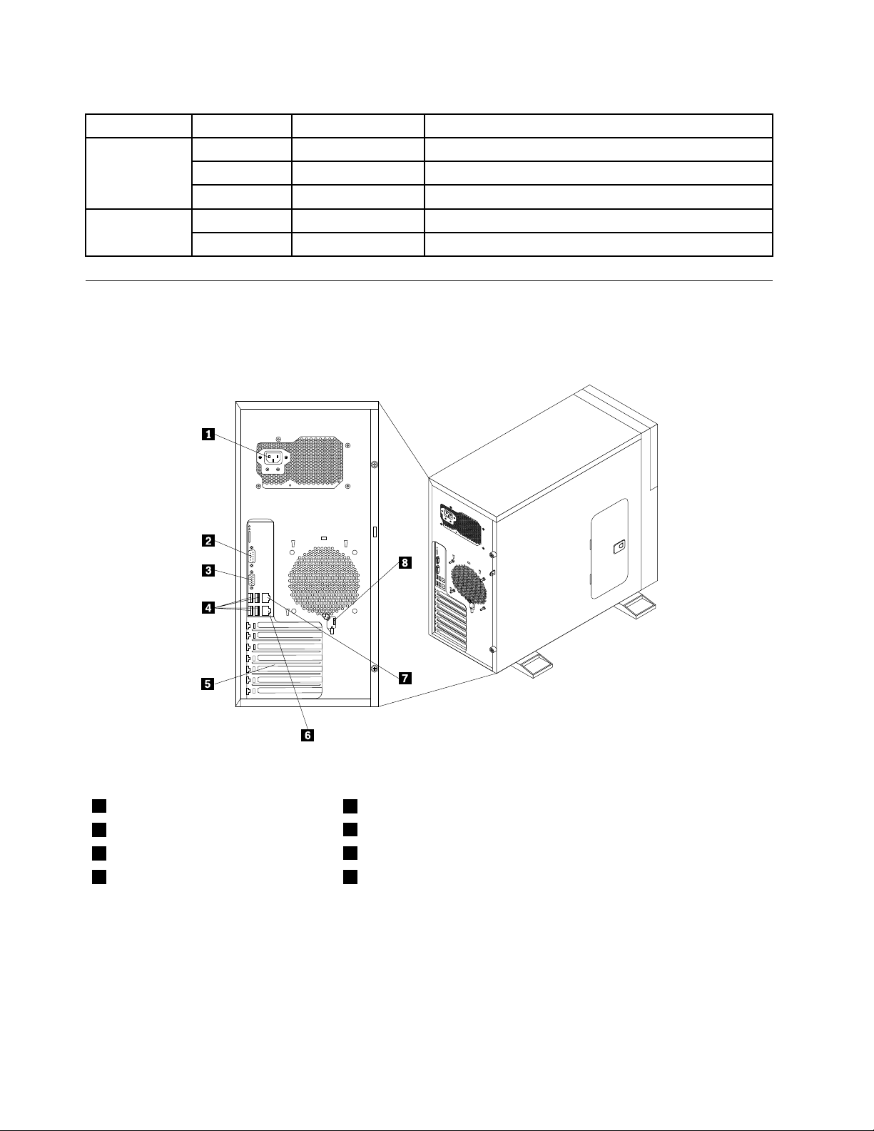
Table4.MeaningsofthestatusLEDsonthefrontpanel(continued)
LEDStateColorDescription
Ethernetstatus
LED
LED
OnGreenTheserverislinkedtoalocalareanetwork(LAN).
Blinking
OffOff
On
OnGreen
Green
Amber
TheLANisactiveanddataisbeingtransferred.
TheserverisnotlinkedtoaLAN.
Thesystemhaserror(s)andalarm(s). Systemstatus
Thesystemisbootedandready.
Rearview
Figure4“Rearviewoftheserver”onpage12showsthelocationsoftheconnectorsandpartsonthe
rearoftheserver.
Figure4.Rearviewoftheserver
1Powercordconnector
2Serialport
3VGAmonitorconnector
4USBconnectors(4)8Frontdoorkey(cuttheplasticcliptogetthekey)
ConnectorDescription
Ethernetconnector
PowercordconnectorUsedtoconnectthepowercord.
Serialport
UsedtoattachanEthernetcableforaLAN.
Usedtoattachadevicethatusesa9-pinserialport.
5PCIcardzone
6Ethernetconnector2
7Ethernetconnector1
12ThinkServerTD230InstallationandUserGuide
Page 23
ConnectorDescription
USBconnectorUsedtoattachadevicethatusesaUSBconnector,suchasaUSBprinter,aUSB
keyboard,oraUSBmouse.IftheUSBconnectorsonyourserverarenotenough
foryoutoconnectallyourUSBdevices,youcanpurchaseaUSBhub,whichyou
canusetoconnectadditionalUSBdevices.
VGAmonitorconnectorUsedtoattachaVGAmonitororotherdevicesthatuseaVGAmonitorconnector.
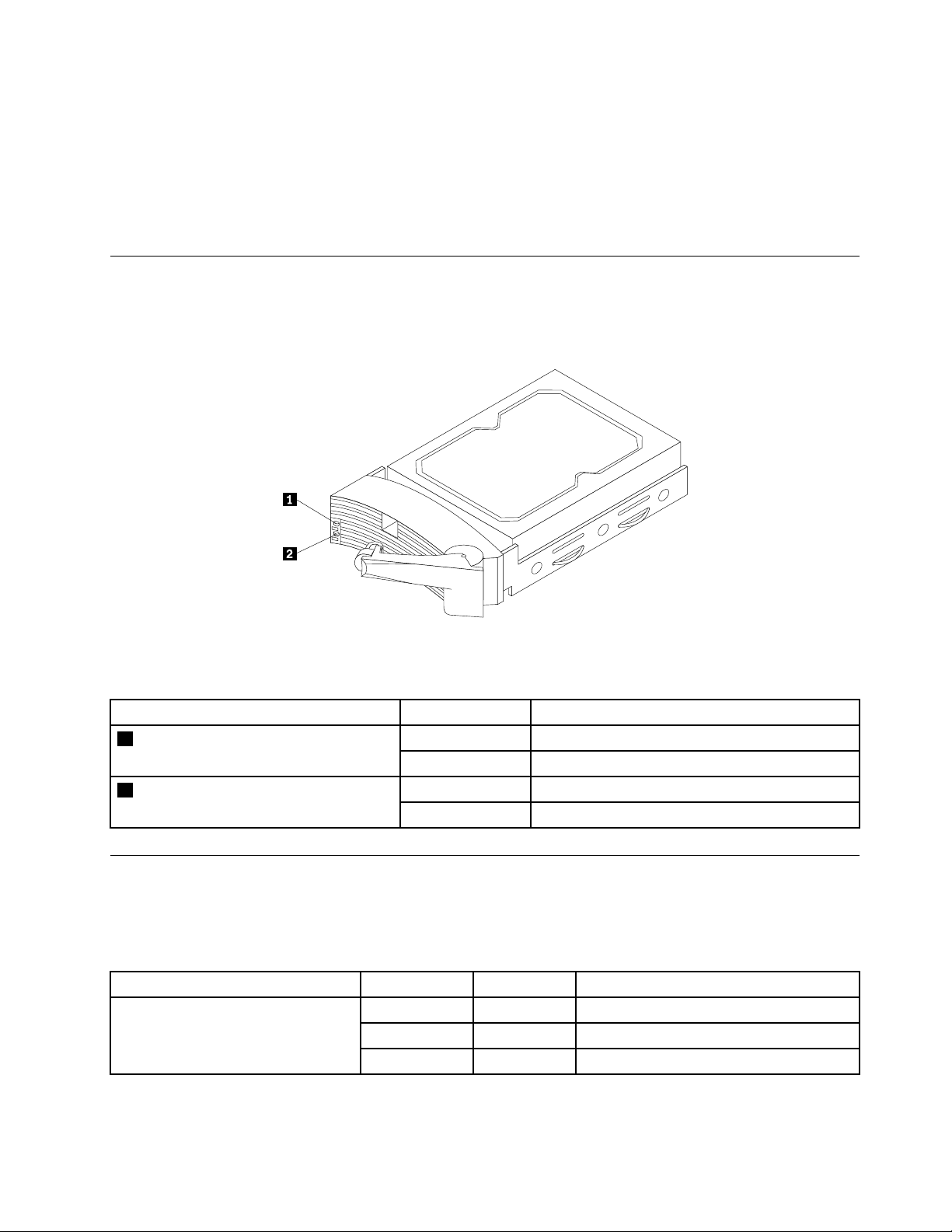
Hot-swapharddiskdrivestatusLEDs
Forservermodelswithhot-swapharddiskdrives,eachhot-swapharddiskdrivealsohastwostatus
LEDsonthefront.
Figure5.Hot-swapharddiskdrivestatusLEDs
Table5.Hot-swapharddiskdrivestatusLEDs
Hot-swapharddiskdrivestatusLEDStateDescription
On
Off
On
Off
Thehot-swapharddiskdriveispresent. 1Hot-swapharddiskdrivepresentLED
Thehot-swapharddiskdriveisnotpresent.
Thehot-swapharddiskdriveisactive. 2Hot-swapharddiskdriveactivityLED
Thehot-swapharddiskdriveisnotactive.
LEDsfortheEthernetconnectors
TheEthernet1andEthernet2connectorshavetwostatusLEDsthatindicatetheLANconnectionand
activityoftheconnection.
Table6.EthernetLEDs
LEDStateColorDescription
RJ-45LinkageandActivity(left)
OnGreen10/100/1000Mblinked
Blinking
OffOff
Green10/100/1000Mbactivity
NoLANconnection.
Chapter4.Locatingparts,controls,LEDs,andconnectors13
Page 24
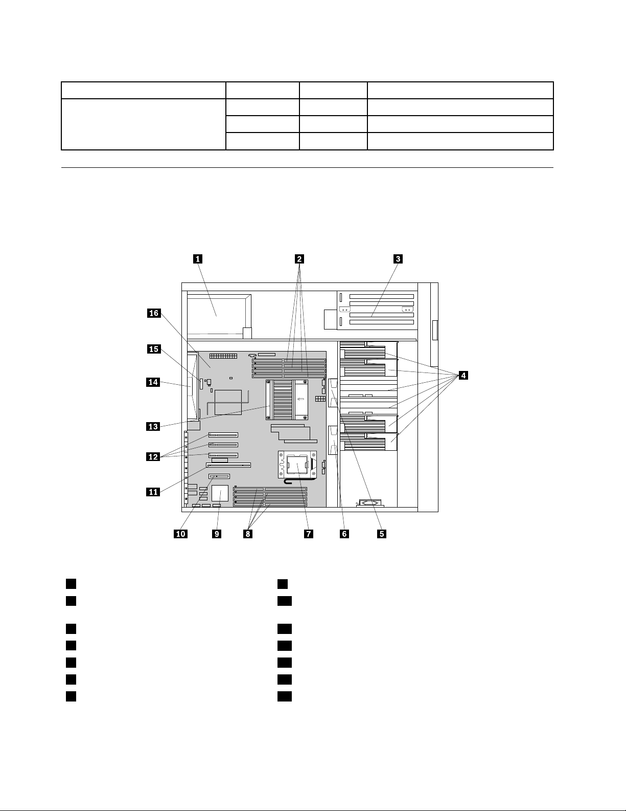
Table6.EthernetLEDs(continued)
LEDStateColorDescription
RJ-45LinkageandActivity(right)
On
OnGreen
OffOff
Amber1000Mblinkedandactive
100Mblinkedandactive
10MbmodeornoLANconnection.
Locatingservercomponents
Figure6“Servercomponentlocations(sideviewwithouttheservercover)”onpage14showsthelocations
ofthemajorcomponentsinyourserver.Toremovetheservercoverandgainaccesstotheinsideofthe
server,see“Removingtheservercover”onpage23.
Figure6.Servercomponentlocations(sideviewwithouttheservercover)
1Powersupplyassembly
2Memoryslotsformicroprocessor1(some
9OnboardICH10RSATARAIDcontroller
10PCIExpressx4slot
slotsmightwithinstalledmemorymodules)
3Opticaldrive11PCIcardslot
4Harddiskdrivezone*
5Systemfan213Heatsinkandfanassembly(microprocessor1underneath)
6Systemfan114Rearfan(systemfan3)
7Microprocessor2socket(thesecond
12PCIExpressx8slots(3)
15Systemboardbattery
microprocessorisoptional)
14ThinkServerTD230InstallationandUserGuide
Page 25
8Memoryslotsformicroprocessor2(some
31
33
34
32
16Systemboard
slotsmightwithinstalledmemorymodules)
Note:*denotesthatthisillustrationonlyshowstheservermodelswithfourhot-swapharddiskdrives.Thereare
alsoservermodelsthatsupportuptovenon-hot-swapharddiskdrives.
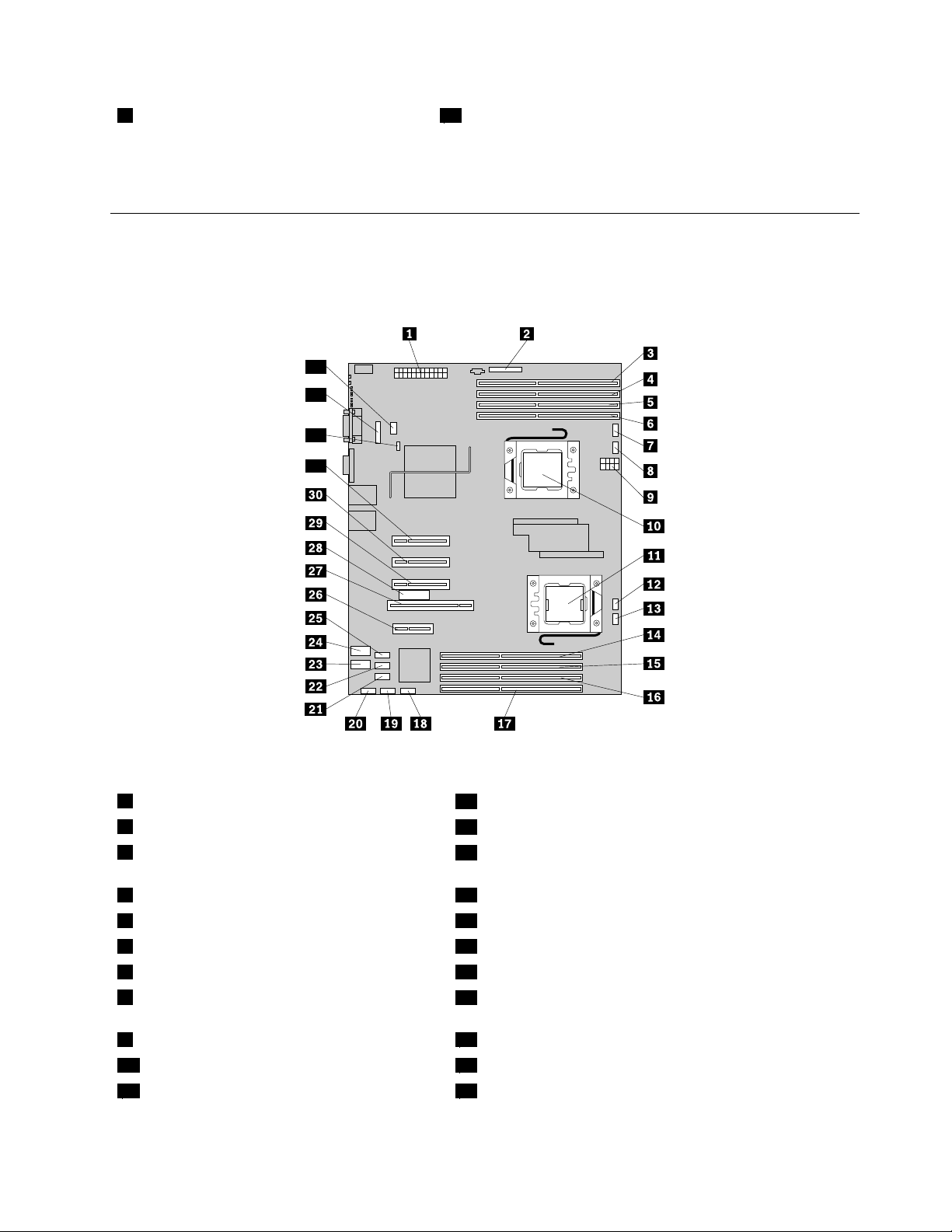
Locatingpartsonthesystemboard
Figure7“Locatingmajorpartsonthesystemboard”onpage15showsthelocationsofthemajorparts
onthesystemboard.
Figure7.Locatingmajorpartsonthesystemboard
1Mainpowerconnector
2Frontpanelconnector
3Memoryslot-microprocessor1DIMMchannel
18SATAconnector0
19SATAconnector1
20SATAconnector2
B1(CPU1DIMMCHB1)
4Memoryslot(CPU1DIMMCHB2)21SATAconnector3
5Memoryslot(CPU1DIMMCHA1)22SATAconnector4
6Memoryslot(CPU1DIMMCHA2)23Internaldual-portUSB2.0connector(ports0-1)
7Systemfan2connector24Internaldual-portUSB2.0connector(ports2-3)
8Microprocessor1heatsinkandfanassembly
25SATAconnector5
connector
9Microprocessorpowerconnector
10Microprocessor1
11Microprocessor2socket(thesecond
26PCIExpressx4slot
27PCIcardslot
28Remotemanagementmodule3(RMM3)connector
microprocessorisoptional)
Chapter4.Locatingparts,controls,LEDs,andconnectors15
Page 26
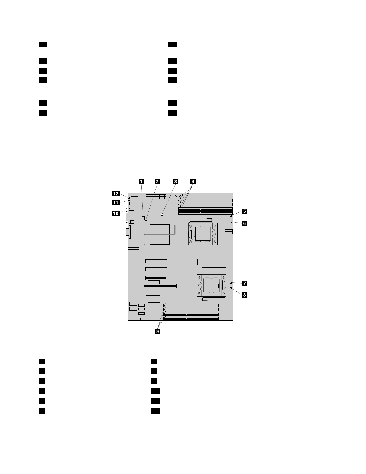
12Microprocessor2heatsinkandfanassembly
29PCIExpressx8slot
connector
13Systemfan1connector30PCIExpressx8slot
14Memoryslot(CPU2DIMMCHD2)31PCIExpressx8slot
15Memoryslot(CPU2DIMMCHD1)32SATAkeyconnectorfortheThinkServerTD230SA TARAID
5Upgrade(see“InstallingorremovingtheThinkServerTD230
SATARAID5Upgrade”onpage58
16Memoryslot(CPU2DIMMCHE2)33Systemboardbattery
17Memoryslot(CPU2DIMMCHE1)34Systemfan3connector
)
LocatingdiagnosticLEDsonthesystemboard
ThereareseveraldiagnosticLEDsonthesystemboardtohelpyoudiagnosespecicproblems.Figure
8“DiagnosticLEDsonthesystemboard”onpage16
thesystemboard.
showsthelocationsofthediagnosticLEDson
Figure8.DiagnosticLEDsonthesystemboard
1HarddiskdriveLED
2Systemfan3faultLED8Systemfan1faultLED
35VSBLED9DIMMfaultLEDs(4)
4DIMMfaultLEDs(4)
5Systemfan2faultLED11StatusLED
6Microprocessor1heatsinkfanfaultLED
7Microprocessor2heatsinkfanfaultLED
10Post-codediagnosticLEDs
12SystemIDLED
16ThinkServerTD230InstallationandUserGuide
Page 27
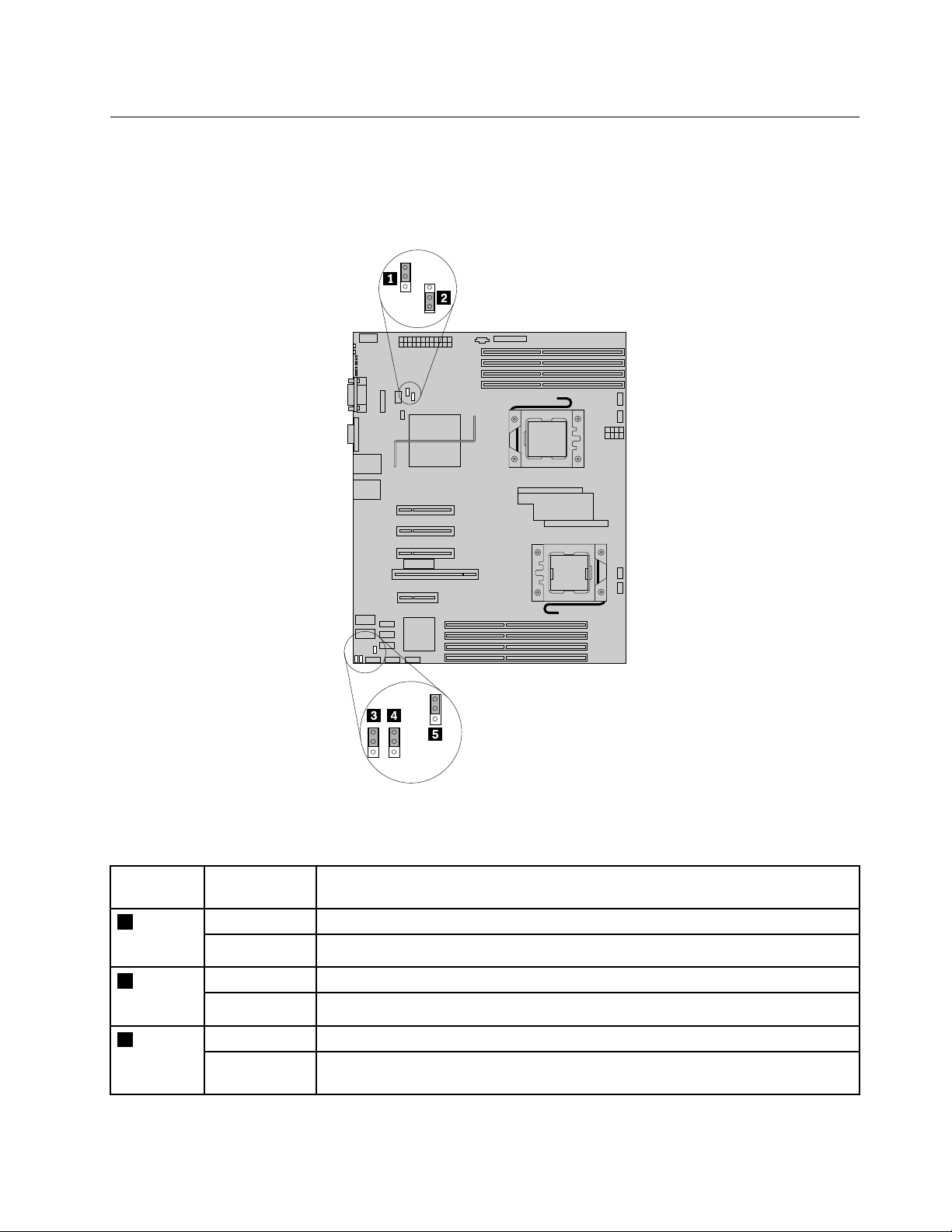
Jumperblocksettings
1
2
3
1
2
3
1
2
3
1
2
3
1
2
3
Thereareseveraljumperblocksonthesystemboardthatcanbeusedtocongure,recover,or
enable/disablespecicfeaturesoftheserversystemboard.Figure9“Jumperblocksonthesystemboard”
onpage17
showsthestatusofthejumperblocksonthesystemboard.
Figure9.Jumperblocksonthesystemboard
Table7.Jumperblocksettings
Jumper
blockPinpositionDescription
1J8B5:
MEForce
Update
BMCforce
update
3J1A1:
BIOS
recovery
Pins1-2
Pins2-3
Pins1-2
Pins2-3
Pins1-2
Pins2-3
Thesepinsshouldhaveajumperinplacefornormalsystemoperation(default).
MEforceupdatemodel.
BMCFirmwareForceUpdateMode–Disabled(default) 2J8C1:
BMCFirmwareForceUpdateMode–Enabled
Thesepinsshouldhaveajumperinplacefornormalsystemoperation(default).
ThemainsystemBIOSwillnotbootwiththesepinsjumpered.Thesystemwillboot
fromabootablerecoverymediawitharecoveryBIOSimage.
Chapter4.Locatingparts,controls,LEDs,andconnectors17
Page 28
Table7.Jumperblocksettings(continued)
Jumper
blockPinpositionDescription
4J2D2:
CMOSclear
5J2D1:
Password
clear
Pins1-2
Pins2-3
Pins1-2
Pins2-3
Thesepinsshouldhaveajumperinplacefornormalsystemoperation(default).
Ifthesepinsarejumpered,theCMOSsettingswillbeclearedonthenextreset.
Thesepinsshouldnotbejumperedfornormaloperation.
Thesepinsshouldhaveajumperinplacefornormalsystemoperation(default).
Ifthesepinsarejumpered,administratoranduserpasswordswillbeclearedonthe
nextreset.Thesepinsshouldnotbejumperedfornormaloperation.
Note:BeforeclearingtheCMOS,turnofftheserveranddisconnectthepowercord.Movethejumperfrom
pins1-2topins2-3.Waitmorethanveminutes;then,movethejumperbacktothenormalposition(pins
1-2isshortcircuited)toclearCMOS.
Locatingconnectorsonthehot-swapharddiskdrivebackplanes
Therearetwohot-swapharddiskdrivebackplanesinstalledintheservermodelwithhot-swapharddisk
drives.Figure10“Connectorlocationsonthehot-swapharddiskdrivebackplanes”onpage19shows
theconnectorlocationsonthehot-swapharddiskdrivebackplanes.
18ThinkServerTD230InstallationandUserGuide
Page 29
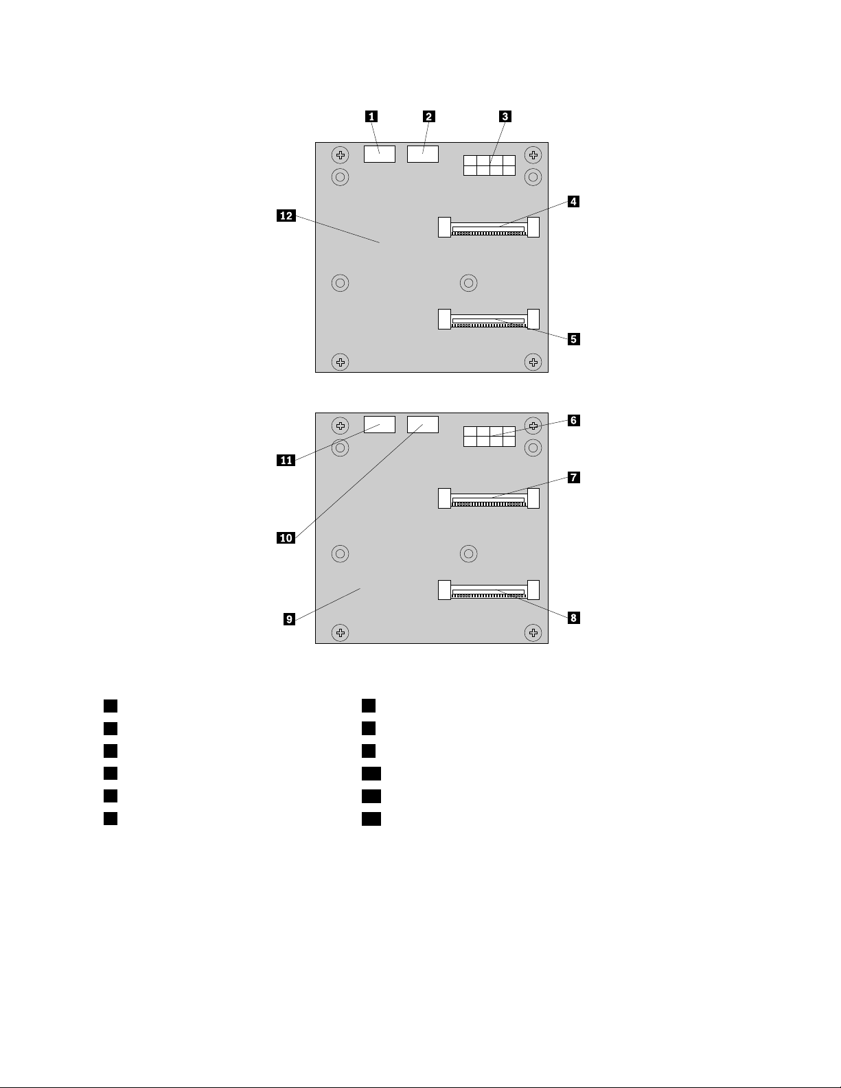
Figure10.Connectorlocationsonthehot-swapharddiskdrivebackplanes
1SATA/SASsignalconnector2
2SATA/SASsignalconnector3
3Powerconnector9Firsthot-swapharddiskdrivebackplane
4Hot-swapharddiskdrive3connector
5Hot-swapharddiskdrive2connector
6Powerconnector
7Hot-swapharddiskdrive1connector
8Hot-swapharddiskdrive0connector
10SATA/SASsignalconnector1
11SATA/SASsignalconnector0
12Secondhot-swapharddiskdrivebackplane
Chapter4.Locatingparts,controls,LEDs,andconnectors19
Page 30

20ThinkServerTD230InstallationandUserGuide
Page 31

Chapter5.Installing,removing,orreplacinghardware
Thischapterprovidesinstructionsonhowtoinstall,remove,orreplacehardwareforyourserver.
Thischaptercontainsthefollowingtopics:
•“Guidelines”onpage21
•“Removingtheservercover”onpage23
•“Removingandreinstallingthefrontbezel”onpage25
•“Installing,removing,orreplacingoptionalhardwaredevices”onpage29
•“Installing,removing,orreplacinghardwaredevices”onpage69
•“Completingthepartsreplacement”onpage90
Guidelines
Thissectionprovidessomeguidelinesthatyoushouldreadandunderstandbeforeusingyourserver.
Basicguidelines
Beforeyouusetheserver,besuretoreadandunderstandthefollowingguidelines:
•BesuretoreadandunderstandtheSafetyInformationandtheWarrantyandSupportInformationonthe
ThinkServerDocumentationDVDthatcomeswithyourproduct,and“Guidelines”onpage21.These
informationwillhelpyouworksafely.Toobtainacopyofthepublications,goto:
http://www.lenovo.com/support
•Whenyouinstallyournewserver,taketheopportunitytodownloadandapplythemostrecentrmware
updates.Thisstepwillhelptoensurethatanyknownissuesareaddressedandthatyourserveris
readytofunctionatmaximumlevelsofperformance.T odownloadrmwareupdatesforyourserver,
dothefollowing:
1.Gotohttp://www.lenovo.com/support.
2.ClickDownload&Drivers➙ThinkServerandthenfollowtheinstructionsontheWebpageto
downloadrmwareupdatesforyourserver.
•Beforeyouinstalloptionalhardwaredevices,makesurethattheserverisworkingcorrectly.Ifan
operatingsystemisinstalled,turnontheserverandmakesurethattheoperatingsystemstarts.Ifno
operatingsystemisinstalled,makesurethata"19990305"errorcodeisdisplayed,indicatingthatan
operatingsystemwasnotfoundbuttheserverisworkingcorrectly.Iftheserverisnotworkingcorrectly,
refertothechapterChapter7“Troubleshooting”onpage111
•Observegoodhousekeepingintheareawhereyouareworking.Putremovedcoversandotherparts
inasafeplace.
•Ifyoumustturnontheserverwhiletheservercoverisremoved,makesurethatnooneisneartheserver
andthatnotoolsorotherobjectshavebeenleftinsidetheserver.
•Donotattempttoliftanobjectthatyouthinkistooheavyforyou.Ifyouhavetoliftaheavyobject,
observethefollowingprecautions:
fordetaileddiagnosticinformation.
–Makesurethatyoucanstandsafelywithoutslipping.
–Distributetheweightoftheobjectequallybetweenyourfeet.
–Useaslowliftingforce.Nevermovesuddenlyortwistwhenyouliftaheavyobject.
–Toavoidstrainingthemusclesinyourback,liftbystandingorbypushingupwithyourlegmuscles.
©CopyrightLenovo2010,2013
21
Page 32

•Makesurethatyouhaveanadequatenumberofproperlygroundedelectricaloutletsfortheserver,
monitor,andotherdevices.
•Backupallimportantdatabeforeyoumakechangestodrives.
•Haveasmallat-bladescrewdriveravailable.
•ToviewtheerrorLEDsonthesystemboardandinternalcomponents,leavetheserverconnectedto
power.
•Youdonothavetoturnofftheservertoinstallorreplacehot-swapfans,redundanthot-swapacpower
supplies,orhot-plugUSBdevices.However,youmustturnofftheserverbeforeperforminganystepsthat
involveinstalling,removing,orreplacingadaptercablesornon-hot-swapoptionaldevicesorcomponents.
•Aftercompletinganyinstallation,removal,orreplacementprocedure,reinstallallsafetyshields,guards,
labels,andgroundwires.
•Foralistofsupportedoptionaldevicesfortheserver,gotohttp://www.lenovo.com/thinkserver.
•Whenworkinginsidetheserver,youmightndsometaskseasierifyoulaytheserveronitsside.You
mightneedtorstpivotthefootstandsinwardandthenlaythecomputeronitsside.
Systemreliabilityguidelines
Tohelpensurepropercoolingandsystemreliability,makesurethatyoufollowtheseguidelines:
•EverydrivebayhasaninternaldriveinstalledoranElectroMagneticCompatibility(EMC)shieldinstalled.
•Iftheserverhasredundantpower,everypowersupplybayhasapowersupplyassemblyinstalled.
•Leaveadequatespacearoundtheservertomakesurethattheservercoolingsystemworkswell.
•Properlyroutethecables.Forsomeoptions,suchasPCIcards,followthecablinginstructionsthat
comewiththeoptions.
•Makesurethatyoureplaceafailedfanwithin48hours.
•Whenreplacingahot-swapdrive,installthenewhot-swapdrivewithintwominutesofremoval.
•Donotremoveanyairductorairbafeswhiletheserverisrunning.Operatingtheserverwithoutthe
airductorairbafesmightcausethemicroprocessortooverheat.
•Thesecondmicroprocessorsocketalwayscontainseitheramicroprocessorsocketcoverora
microprocessorandheatsink.
Handlingstatic-sensitivedevices
Attention:
Donotopenthestatic-protectivepackagecontainingthenewpartuntilthedefectiveparthasbeenremovedfromthe
serverandyouarereadytoinstallthenewpart.Staticelectricity,althoughharmlesstoyou,canseriouslydamage
servercomponentsandparts.
Whenyouhandleserverpartsandcomponents,taketheseprecautionstoavoidstatic-electricitydamage:
•Limityourmovement.Movementcancausestaticelectricitytobuilduparoundyou.
•Wearanelectrostatic-dischargewriststrap,ifoneisavailable.
•Alwayscarefullyhandlethepartsandothercomponents(suchasPCIcards,memorymodules,system
boards,andmicroprocessors)byitsedgesoritsframe.Donottouchsolderjoints,pins,orexposed
circuitry.
•Preventothersfromtouchingthepartsandothercomputercomponents.
•Beforeyoureplaceanewpart,touchthestatic-protectivepackagecontainingthenewparttoametal
expansion-slotcoverorotherunpaintedmetalsurfaceontheserverforatleasttwoseconds.This
reducesstaticelectricityfromthepackageandyourbody.
22ThinkServerTD230InstallationandUserGuide
Page 33

•Removethenewpartfromthestatic-protectivepackageanddirectlyinstallitintheserverwithout
placingitonanyothersurface.Ifitishardforyoutodothisinyourspecicsituation,placethe
static-protectivepackageofthenewpartonasmooth,levelsurface,andthenplacethenewparton
thestatic-protectivepackage.
•Donotplacethepartontheservercoverorothermetalsurface.
•Takeadditionalcarewhenhandlingdevicesduringcoldweather.Heatingreducesindoorhumidity
andincreasesstaticelectricity.
Workinginsidetheserverwiththepoweron
Attention:
Staticelectricitythatisreleasedtointernalservercomponentswhentheserveristurnedonmightcausetheserverto
halt,whichmightresultinthelossofdata.Toavoidthispotentialproblem,alwaysuseanelectrostatic-dischargewrist
straporothergroundingsystemwhenyouworkinsidetheserverwiththepoweron.
Theserversupportshot-swapdevicesandisdesignedtooperatesafelywhileitisturnedonandthecoveris
removed.Followtheseguidelineswhenyouworkinsidetheserverwiththepoweron:
•Avoidwearingloose-ttingclothingonyourforearms.Buttonlong-sleevedshirtsbeforeworkinginside
theserver;donotwearcufflinkswhileyouareworkinginsidetheserver.
•Donotallowyournecktieorscarftohanginsidetheserver.
•Removejewelry,suchasbracelets,necklaces,rings,andloose-ttingwristwatches.
•Removeitemsfromyourshirtpocket,suchaspensandpencils.Theseitemsmightfallintotheserveras
youleanoverit.
•Avoiddroppinganymetallicobjectsintotheserver,suchaspaperclips,hairpins,andscrews.
Removingtheservercover
Attention:
DonotopenyourserverorattemptanyrepairbeforereadingandunderstandingtheSafetyInformationandthe
WarrantyandSupportInformationontheThinkServerDocumentationDVDthatcamewithyourproduct,and
“Guidelines”onpage21.Toobtainacopyofthepublications,goto:
http://www.lenovo.com/support
Thissectionprovidesinstructionsonhowtoremovetheservercover.
Attention:Forpropercoolingandairow,installtheservercoverbeforeturningontheserver.Operatingthe
serverformorethan30minuteswiththeservercoverremovedmightdamageservercomponents.
Toremovetheservercover,dothefollowing:
1.Removeallmediafromthedrives.Then,turnoffallattacheddevicesandtheserver.
2.Disconnectallpowercordsfromelectricaloutlets.
3.Disconnectthepowercord,Input/Output(I/O)cables,andallothercablesthatareconnectedtothe
server.
4.Removeanylockingdevicethatsecurestheservercover,suchasapadlock.
Chapter5.Installing,removing,orreplacinghardware23
Page 34

5.Loosenthetwothumbscrewsattachedontherearoftheservercoverandthenslidetheservercover
totherear.
Notes:
a.Thetwothumbscrewsaresecurelyinstalledandyouneedtouseatool,forexampleascrewdriver,
toloosenthethumbscrews.
b.Thetwothumbscrewsareintegratedpartsoftheservercoverandtheycannotberemovedfrom
theservercover.
Figure11.Slidingtheservercovertotherear
24ThinkServerTD230InstallationandUserGuide
Page 35

6.Pivottheservercoveroutwardtocompletelyremoveit.
Figure12.Removingtheservercover
Toreinstalltheservercover,see“Installingtheservercover”onpage91.
Removingandreinstallingthefrontbezel
Attention:
DonotopenyourserverorattemptanyrepairbeforereadingandunderstandingtheSafetyInformationandthe
WarrantyandSupportInformationontheThinkServerDocumentationDVDthatcamewithyourproduct,and
“Guidelines”onpage21.Toobtainacopyofthepublications,goto:
http://www.lenovo.com/support
Thissectionprovidesinstructionsonhowtoremoveandreinstallthefrontbezel.
Toremoveandreinstallthefrontbezel,dothefollowing:
1.Removeallmediafromthedrivesandturnoffallattacheddevicesandtheserver.Then,disconnectall
powercordsfromelectricaloutletsanddisconnectallcablesthatareconnectedtotheserver.
2.Removetheservercover.See“Removingtheservercover”onpage23.
Chapter5.Installing,removing,orreplacinghardware25
Page 36

3.Removethefrontbezelbyreleasingthethreeplastictabs1ontheleftsideandpullingthefront
bezeloutward.
Figure13.Removingthefrontbezel
4.Toreinstallthefrontbezel,aligntheotherthreeplastictabsontherightsideofthefrontbezelwith
thecorrespondingholesinthechassis,thenpivotthefrontbezelinwarduntilitsnapsintoposition
ontheleftside.
5.Goto“Completingthepartsreplacement”onpage90.
Lockingorunlockingtheharddiskdrivesidedoor
Attention:
DonotopenyourserverorattemptanyrepairbeforereadingandunderstandingtheSafetyInformationandthe
WarrantyandSupportInformationontheThinkServerDocumentationDVDthatcamewithyourproduct,and
“Guidelines”onpage21.Toobtainacopyofthepublications,goto:
http://www.lenovo.com/support
Thissectionprovidesinstructionsonhowtolockorunlocktheharddiskdrivesidedoor.
26ThinkServerTD230InstallationandUserGuide
Page 37

Theharddiskdrivesidedooroftheserverisunlockedwhenshippedfromthefactory.Y oucanopentheside
doortoviewthehot-swapharddiskdriveLEDstatus,installanewharddiskdrive,andremoveorreplacea
failingharddiskdrive.However,youcanalsolocktheharddiskdrivesidedoortoensurethatallthehard
diskdrivescannotbeaccessedunlessyouremovetheservercover.Ifyoudoso,youmustturnoffthe
server,disconnectallpowercords,andremovetheservercoverwhenyouwanttoreplaceanyharddisk
drives,includingthehot-swapharddiskdrives.
Tolockorunlocktheharddiskdrivesidedoor,dothefollowing:
1.Pressthebluebutton1toopenthesidedoor.
Figure14.Openingthesidedoor
Chapter5.Installing,removing,orreplacinghardware27
Page 38

2.Rotatetheplasticlatchofthesidedoortotheclosedposition.Then,closethesidedooruntilitsnaps
intoposition.Thesidedoorislockedandcannotbeopenedwhenyoupressthebluebutton.
Figure15.Lockingthesidedoor
28ThinkServerTD230InstallationandUserGuide
Page 39

3.Tounlockthesidedoor,removetheservercover.See“Removingtheservercover”onpage23.Then,
rotatetheplasticlatchofthesidedoortotheopenposition.Reinstalltheservercover.See“Installing
theservercover”onpage91.Thesidedoorisunlockedandyoucanopenthesidedoorbypressing
thebluebuttononit,asshowninFigure14“Openingthesidedoor”onpage27
Figure16.Unlockingthesidedoor
.
Installing,removing,orreplacingoptionalhardwaredevices
Thissectionprovidesinstructionsonhowtoinstall,remove,orreplaceoptionalhardwaredevicesforyour
server.Youcanexpandthecapabilitiesofyourserverbyaddingmemorymodules,PCIcards,ordrives,
andmaintainyourserverbyreplacingthefailingoptionalhardwaredevices.Ifyouarereplacinganoptional
hardwaredevice,performtheremovalprocedureandthenperformtheinstallationprocedurefortheoptional
hardwaredevicethatyouwanttoreplace.
Installingorremovingamemorymodule
Thissectionprovidesinstructionsonhowtoinstallorremoveamemorymodule.Foralistofthesupported
memorymodulesforyourserver,gotohttp://www.lenovo.com/thinkserver.OntheThinkServersystems
page,clickProducts➙Options➙ThinkServerMemory.
Memorymoduleinstallationrules
YourserverhaseightmemoryslotsforinstallingorreplacingDDR3SDRAMDIMMsthatprovideuptoa
maximumof32GBofsystemmemory.
Thefollowingtableprovidesinformationaboutthememorymoduleinstallationrulesthatyoushould
considerwheninstallingamemorymodule.The“X”markindicatesthesuggestedmemoryslot(s)into
whichthememorymodule(s)shouldbeinstalledindifferentsituations.Thenumber,forexample1,2,or3,
indicatestheinstallationsequence.See“Locatingpartsonthesystemboard”onpage15toidentifythe
variousmemoryslots.
Note:Allmemorymoduletypesandcapacitiesmustbeconsistent.
Chapter5.Installing,removing,orreplacinghardware29
Page 40

Table8.Memorymoduleinstallationrules
CPU1
DIMM
CPUDIMM
CPU1
CPU1
andCPU
2
Note:*denotestheChannelMirroringMode.ThismoderequiresthatyouinstalltheDIMMsinpair.
One
DIMM
Two
DIMMs*
Four
DIMMs
Two
DIMMs
Four
DIMMs*
Six
DIMMs
Eight
DIMMs
CHA2
X,3X,1X,4X,2
X,5X,1X,3X,6X,2X,4
X,5X,1X,7X,3X,6X,2X,8X,4
CPU1
DIMM
CHA1
X
X,1X,2
X,1X,2
X,1X,3X,2X,4
CPU1
DIMM
CHB2
CPU1
DIMM
CHB1
CPU2
DIMM
CHD2
CPU2
DIMM
CHD1
Installingamemorymodule
Attention:
CPU2
DIMM
CHE2
CPU2
DIMM
CHE1
DonotopenyourserverorattemptanyrepairbeforereadingandunderstandingtheSafetyInformationandthe
WarrantyandSupportInformationontheThinkServerDocumentationDVDthatcamewithyourproduct,and
“Guidelines”onpage21.Toobtainacopyofthepublications,goto:
http://www.lenovo.com/support
Thissectionprovidesinstructionsonhowtoinstallamemorymodule.
Toinstallamemorymodule,dothefollowing:
1.Removeallmediafromthedrivesandturnoffallattacheddevicesandtheserver.Then,disconnectall
powercordsfromelectricaloutletsanddisconnectallcablesthatareconnectedtotheserver.
2.Removetheservercover.See“Removingtheservercover”onpage23.
3.Locatetheappropriatememoryslotonthesystemboardintowhichyouwillinstallthememorymodule.
Tooptimizesystemperformance,followtherelatedmemorymoduleinstallationrulesandinstallthe
memorymoduleintoamemoryslotstartingwiththememorymodulefarthestfromthemicroprocessor.
See“Memorymoduleinstallationrules”onpage29.
30ThinkServerTD230InstallationandUserGuide
Page 41

4.Opentheretainingclipsofthememoryslotintowhichyouwanttoinstallthememorymodule.
Figure17.Openingtheretainingclipsofthememoryslot
5.Touchthestatic-protectivepackagethatcontainsthenewmemorymoduletoanyunpaintedmetal
surfaceontheoutsideoftheserver.Then,removethenewmemorymodulefromthepackage.
6.Positionthenewmemorymoduleoverthememoryslot.Makesurethatthenotch1onthenewmemory
moduleisalignedwiththekey2inthememoryslot.Then,pressthenewmemorymodulestraightdown
intothememoryslotuntiltheretainingclipscloseandthenewmemorymodulesnapsintoposition.
Note:Ifthereisagapbetweenthememorymoduleandtheretainingclips,thememorymodulehas
notbeencorrectlyinstalled.Opentheretainingclips,removethememorymodule,andthenreinstallit
intotheslot.
Figure18.Installingthememorymodule
Whattodonext:
•Toworkwithanotherpieceofhardware,gototheappropriatesection.
•Tocompletetheinstallationorreplacement,goto“Completingthepartsreplacement”onpage90
Removingamemorymodule
Attention:
DonotopenyourserverorattemptanyrepairbeforereadingandunderstandingtheSafetyInformationandthe
WarrantyandSupportInformationontheThinkServerDocumentationDVDthatcamewithyourproduct,and
“Guidelines”onpage21.Toobtainacopyofthepublications,goto:
http://www.lenovo.com/support
Chapter5.Installing,removing,orreplacinghardware31
.
Page 42

Thissectionprovidesinstructionsonhowtoremoveamemorymodule.
Toremoveamemorymodule,dothefollowing:
1.Removeallmediafromthedrivesandturnoffallattacheddevicesandtheserver.Then,disconnectall
powercordsfromelectricaloutletsanddisconnectallcablesthatareconnectedtotheserver.
2.Removetheservercover.See“Removingtheservercover”onpage23.
3.Locatethememoryslotwiththememorymodulethatyouwanttoremove.See“Locatingpartsonthe
systemboard”onpage15forthelocationsofthememoryslots.
4.Carefullyopentheretainingclipsoneachendofthememoryslotandthengraspthememorymodule
straightupbyitsedges.
Figure19.Removingthememorymodule
5.Ifyouareinstructedtoreturnthefailingmemorymodule,followallpackaginginstructions,anduseany
packagingmaterialsforshippingthataresuppliedtoyou.
Whattodonext:
•Toworkwithanotherpieceofhardware,gototheappropriatesection.
•Tocompletetheremovalprocedure,goto“Completingthepartsreplacement”onpage90.
Removingorinstallinginternaldrives
Thissectionprovidesinstructionsonhowtoremoveorinstallinternaldrivesfortheserver.See“Features
andspecications”onpage5
see“Locatingservercomponents”onpage14forthelocationsofthedrivebaysintheserver.
Wheninstallinganinternaldrive,besuretoconsiderthefollowinginformation:
•Makesurethatyouhaveallthecablesandotherequipmentspeciedinthedocumentationthatcame
withthedrive.
•Notethetypeandsizeofthedriveandselecttheappropriatedrivebaytoinstallthedrive.
•Checktheinstructionsthatcamewiththedrivetoseewhetheryouhavetosetanyswitchesorjumpers
onthedrive.IfyouareinstallingaSASdevice,besuretosettheSASIDforthatdevice.
•TheEMIintegrityandcoolingoftheserverareprotectedbyhavingalldrivebaysandPCIcardslots
coveredoroccupied.WhenyouinstalladriveoraPCIcard,savetheEMCshieldorllerpanelfromthe
drivebayorsavethePCIcardslotcoverintheeventthatyoulaterremovethedevice.Anunoccupied
drivebayorPCIcardslotwithoutcover,shield,ller,oranyotherprotectionmightimpacttheEMI
integrityandcoolingoftheserver,whichmightresultinoverheatingorcomponentdamage.
forinformationaboutthetypesofinternaldrivesthattheserversupportsand
32ThinkServerTD230InstallationandUserGuide
Page 43

•Foralistofthesupportedharddiskdrivesforyourserver,gotohttp://www.lenovo.com/thinkserver.On
theThinkServersystemspage,clickProducts➙Options➙ThinkServerHardDrives.
Removingtheopticaldrive
Attention:
DonotopenyourserverorattemptanyrepairbeforereadingandunderstandingtheSafetyInformationandthe
WarrantyandSupportInformationontheThinkServerDocumentationDVDthatcamewithyourproduct,and
“Guidelines”onpage21.Toobtainacopyofthepublications,goto:
http://www.lenovo.com/support
Thissectionprovidesinstructionsonhowtoremovetheopticaldrive.
Toremovetheopticaldrive,dothefollowing:
1.Removeallmediafromthedrivesandturnoffallattacheddevicesandtheserver.Then,disconnectall
powercordsfromelectricaloutletsanddisconnectallcablesthatareconnectedtotheserver.
2.Removetheservercover.See“Removingtheservercover”onpage23.
3.Removethefrontbezel.See“Removingandreinstallingthefrontbezel”onpage25.
4.Disconnectthesignalcableandthepowercablefromtherearoftheopticaldrive.
Chapter5.Installing,removing,orreplacinghardware33
Page 44

5.Presstheopticaldriveretainers1onbothsidesoftheopticaldriveandslidetheopticaldriveoutof
thefrontoftheserver.
Figure20.Removingtheopticaldrive
6.Removetheopticaldriveretainersfrombothsidesoftheoldopticaldriveandsavethemtousewhen
youinstallanewopticaldrive.
Figure21.Removingtheopticaldriveretainers
34ThinkServerTD230InstallationandUserGuide
Page 45

7.Ifyouareinstructedtoreturntheremovedopticaldrivetothemanufacturer,followallpackaging
instructionsanduseanypackagingmaterialsthataresuppliedtoyouforshipping.
Whattodonext:
•Toworkwithanotherpieceofhardware,gototheappropriatesection.
•Tocompletetheremovalprocedure,goto“Completingthepartsreplacement”onpage90.
Installingtheopticaldrive
Attention:
DonotopenyourserverorattemptanyrepairbeforereadingandunderstandingtheSafetyInformationandthe
WarrantyandSupportInformationontheThinkServerDocumentationDVDthatcamewithyourproduct,and
“Guidelines”onpage21.Toobtainacopyofthepublications,goto:
http://www.lenovo.com/support
Thissectionprovidesinstructionsonhowtoinstalltheopticaldrive.
Toinstalltheopticaldrive,dothefollowing:
1.Ifyouarereplacingtheopticaldrive,makesurethat:
•Youhaveallthecablesandotherequipmentthatisspeciedinthedocumentationthatcomes
withthenewopticaldrive.
•Youhavecheckedtheinstructionsthatcomewiththenewopticaldrivetodeterminewhetheryou
mustsetanyswitchesorjumpersintheopticaldrive.
•Youhaveremovedtheopticaldriveretainersfrombothsidesoftheoldopticaldriveandhavethem
availableforinstallationonthenewopticaldrive.
Note:Ifyouareinstallingalaserdevice(suchasadrive),observethefollowingsafetyprecautions.
Statement3
CAUTION:
Whenlaserproducts(suchasCD-ROMs,DVDdrives,beropticdevices,ortransmitters)are
installed,notethefollowing:
•Donotremovethecovers.Removingthecoversofthelaserproductcouldresultinexposure
tohazardouslaserradiation.Therearenoserviceablepartsinsidethedevice.
•Useofcontrolsoradjustmentsorperformanceofproceduresotherthanthosespeciedherein
mightresultinhazardousradiationexposure.
DANGER
SomelaserproductscontainanembeddedClass3AorClass3Blaserdiode.Notethefollowing.
Laserradiationwhenopen.Donotstareintothebeam,donotviewdirectlywithoptical
instruments,andavoiddirectexposuretothebeam.
2.Removeallmediafromthedrivesandturnoffallattacheddevicesandtheserver.Then,disconnectall
powercordsfromelectricaloutletsanddisconnectallcablesthatareconnectedtotheserver.
3.Removetheservercover.See“Removingtheservercover”onpage23.
4.Removethefrontbezel.See“Removingandreinstallingthefrontbezel”onpage25.
Chapter5.Installing,removing,orreplacinghardware35
Page 46

5.Touchthestatic-protectivepackagethatcontainsthenewopticaldrivetoanyunpaintedmetalsurface
ontheserver.Then,removethenewopticaldrivefromthepackageandplaceitonastatic-protective
surface.
6.Installtheopticaldriveretainersonbothsidesofthenewopticaldrive.
Note:Notetheorientationoftheopticaldriveretainersandthecorrespondingholesinbothsides
oftheopticaldrivewheninstallingtheretainers.
Figure22.Installingtheopticaldriveretainers
36ThinkServerTD230InstallationandUserGuide
Page 47

7.Slidethenewopticaldriveintothedrivebayuntilitsnapsintoposition.
Figure23.Installingtheopticaldrive
8.Connectoneendofthesignalcable2totherearofthenewopticaldriveandtheotherendtoan
availableSATAconnector(SATAconnector5recommended)onthesystemboard.See“Locating
partsonthesystemboard”onpage15.Then,locateanavailableve-wirepowerconnector1and
connectittotherearofthenewopticaldrive.
Figure24.Connectingtheopticaldrivecables
Chapter5.Installing,removing,orreplacinghardware37
Page 48

Whattodonext:
•Toworkwithanotherpieceofhardware,gototheappropriatesection.
•Tocompletetheinstallation,goto“Completingthepartsreplacement”onpage90.
Removingahot-swapharddiskdrive
Attention:
DonotopenyourserverorattemptanyrepairbeforereadingandunderstandingtheSafetyInformationandthe
WarrantyandSupportInformationontheThinkServerDocumentationDVDthatcamewithyourproduct,and
“Guidelines”onpage21.Toobtainacopyofthepublications,goto:
http://www.lenovo.com/support
Thissectionprovidesinstructionsonhowtoremoveahot-swapharddiskdrive.Thissectionappliesonlyto
servermodelsthathavehot-swapharddiskdrivesinstalled.
Attention:Tomaintainpropersystemcooling,donotoperatetheserverformorethan10minuteswithout
eitheradriveorallerpanelinstalledineachdrivebay.
Toremoveahot-swapharddiskdrive,dothefollowing:
Note:Youdonothavetoturnofftheserverwhenremovingahot-swapharddiskdrive.However,ifyou
havelockedthesidedoor,youmustturnofftheserver,disconnectallpowercords,andremovetheserver
coverwhenyouwanttoremove,install,orreplaceanyharddiskdrives.See“Lockingorunlockingthehard
diskdrivesidedoor”onpage26
1.Pressthebluebutton1toopenthesidedoor.
and“Removingtheservercover”onpage23.
Figure25.Openingthesidedoor
38ThinkServerTD230InstallationandUserGuide
Page 49

2.Locatethehot-swapharddiskdriveyouwanttoremove.Then,pressthebluereleasebutton1and
rotatethehandleoftheharddiskdrivebrackettotheopenposition.
Figure26.Openingthehandleofthehot-swapharddiskdrivebracket
Chapter5.Installing,removing,orreplacinghardware39
Page 50

3.Graspthehandle1andpulltheharddiskdrivebracketwiththeharddiskdriveoutofthedrivebay.
Figure27.Removingthehot-swapharddiskdrivebracketwiththeharddiskdrive
40ThinkServerTD230InstallationandUserGuide
Page 51

4.Removethefourscrewsthatsecuretheharddiskdriveandthenremovetheharddiskdrivefrom
thebracket.
Figure28.Removingthehot-swapharddiskdrive
5.Ifyouareinstructedtoreturntheremovedhot-swapharddiskdrivetothemanufacturer,followall
packaginginstructionsanduseanypackagingmaterialsthataresuppliedtoyouforshipping.
Whattodonext:
•Toworkwithanotherpieceofhardware,gototheappropriatesection.
•Tocompletetheremovalprocedure,goto“Completingthepartsreplacement”onpage90.
Installingahot-swapharddiskdrive
Attention:
DonotopenyourserverorattemptanyrepairbeforereadingandunderstandingtheSafetyInformationandthe
WarrantyandSupportInformationontheThinkServerDocumentationDVDthatcamewithyourproduct,and
“Guidelines”onpage21.Toobtainacopyofthepublications,goto:
http://www.lenovo.com/support
Thissectionprovidesinstructionsonhowtoinstallahot-swapharddiskdrive.Thissectionappliesonlyto
servermodelsthatsupporthot-swapharddiskdrives.
Attention:Tomaintainpropersystemcooling,donotoperatetheserverformorethan10minuteswithout
eitheradriveorallerpanelinstalledineachdrivebay.
Toinstallahot-swapharddiskdrive,dothefollowing:
Notes:
1.Youdonothavetoturnofftheserverfortheinstallationofahot-swapharddiskdrive.However,if
youhavelockedthesidedoor,youmustturnofftheserver,disconnectallpowercords,andremove
theservercoverwhenyouwanttoremove,install,orreplaceanyharddiskdrives.See“Lockingor
unlockingtheharddiskdrivesidedoor”onpage26
2.Thecablescomewiththeharddiskdriveoptionkitwillnotbeusedifyouareinstallingahot-swap
harddiskdrive.
and“Removingtheservercover”onpage23.
Chapter5.Installing,removing,orreplacinghardware41
Page 52

1.Pressthebluebutton1toopenthesidedoor.
Figure29.Openingthesidedoor
42ThinkServerTD230InstallationandUserGuide
Page 53

2.Locateahot-swapharddiskdrivebaythatyouwanttoinstallthedrive.Then,pressthebluerelease
button1androtatethehandleoftheharddiskdrivebrackettotheopenposition.
Figure30.Openingthehandleofthehot-swapharddiskdrivebracket
Chapter5.Installing,removing,orreplacinghardware43
Page 54

3.Graspthehandle1andpulltheharddiskdrivebracketoutofthedrivebay.
Figure31.Removingthehot-swapharddiskdrivebracket
4.Removetheplasticdrivebayllerandsaveitforfutureuse.
Note:TheEMIintegrityandcoolingoftheserverareprotectedbyhavingalldrivebaysandPCIcard
slotscoveredoroccupied.WhenyouinstalladriveorPCIcard,savetheEMCshieldordrivebayller
fromthedrivebayorsavethePCIcardslotcoverintheeventthatyoulaterremovethedevice.An
unoccupieddrivebayorPCIcardslotwithoutcover,shield,ller,oranyotherprotectionmightimpact
theEMIintegrityandcoolingoftheserver,whichmightresultinoverheatingorcomponentdamage.
5.Touchthestatic-protectivepackagethatcontainsthenewharddiskdrivetoanyunpaintedmetal
surfaceontheserver.Then,removetheharddiskdrivefromthepackage.
44ThinkServerTD230InstallationandUserGuide
Page 55

6.Alignthescrewholesinbothsidesoftheharddiskdrivewiththecorrespondingholesintheharddisk
drivebracket.Then,installthefourscrewstosecuretheharddiskdriveinthebracket.
Note:Carefullyinstalltheharddiskdrivewithouttouchingthecircuitboardonthebottomofthe
harddiskdrive.
Figure32.Installingtheharddiskdriveintothebracket
7.Keepthehandleofthehot-swapharddiskdrivebracketfullyopenandthenslidethebracketwiththe
harddiskdriveintothedrivebayuntilitcannotbepushedinanymore.
Figure33.Slidingthehot-swapharddiskdrivebracketwiththeharddiskdriveintothebay
Chapter5.Installing,removing,orreplacinghardware45
Page 56

8.Pressthehandle1torotateittotheclosedpositionuntilthebluereleasebuttonsnapsintoplaceand
thebracketwiththeharddiskdriveissecurelylockedinthedrivebay.
Figure34.Lockingthehot-swapharddiskdriveinthedrivebay
9.ChecktheharddiskdrivestatusLEDstomakesurethattheharddiskdriveisoperatingcorrectly.Y ou
mighthavetorestarttheserverforthenewlyinstalleddrivetoberecognized.Iftheamberharddiskdrive
statusLEDislitcontinuously,thisindicatesthattheharddiskdriveisfaultyandmustbereplaced;ifthe
greenharddiskdrivestatusLEDisblinking,thisindicatesthattheharddiskdriveisoperatingcorrectly.
Note:IftheserverisconguredforRAIDoperationusingaRAIDcontroller,youmighthaveto
recongurethediskarraysafteryoureplaceharddiskdrives.
Whattodonext:
•Toworkwithanotherpieceofhardware,gototheappropriatesection.
•Tocompletetheinstallation,goto“Completingthepartsreplacement”onpage90
.
46ThinkServerTD230InstallationandUserGuide
Page 57

Removinganon-hot-swapharddiskdrive
Attention:
DonotopenyourserverorattemptanyrepairbeforereadingandunderstandingtheSafetyInformationandthe
WarrantyandSupportInformationontheThinkServerDocumentationDVDthatcamewithyourproduct,and
“Guidelines”onpage21.Toobtainacopyofthepublications,goto:
http://www.lenovo.com/support
Thissectionprovidesinstructionsonhowtoremoveanon-hot-swapharddiskdrive.Thissectionapplies
onlytoservermodelsthathavenon-hot-swapharddiskdrivesinstalled.
Attention:Tomaintainpropersystemcooling,donotoperatetheserverformorethan10minuteswithout
eitheradriveorallerpanelinstalledineachdrivebay.
Toremoveanon-hot-swapharddiskdrive,dothefollowing:
1.Removeallmediafromthedrivesandturnoffallattacheddevicesandtheserver.Then,disconnectall
powercordsfromelectricaloutletsanddisconnectallcablesthatareconnectedtotheserver.
2.Pressthebluebutton1toopenthesidedoor.
Note:Ifyouhavelockedthesidedoor,youmustturnofftheserver,disconnectallpowercords,and
removetheservercoverwhenyouwanttoremove,install,orreplaceanyharddiskdrives.See“Locking
orunlockingtheharddiskdrivesidedoor”onpage26
and“Removingtheservercover”onpage23.
Figure35.Openingthesidedoor
Chapter5.Installing,removing,orreplacinghardware47
Page 58

3.Locatethenon-hot-swapharddiskdriveyouwanttoremoveanddisconnectthepowercableandthe
signalcablefromtheharddiskdrive.Then,pullthehandleoftheharddiskdrivebrackettoslidethe
bracketwiththeharddiskdriveoutofthedrivebay.
Figure36.Disconnectingcablesandslidingthenon-hot-swapharddiskdriveout
4.Dependingonthenon-hot-swapharddiskdriveissecuredinthebracketbyscrewsorplasticretainers,
dooneofthefollowing:
48ThinkServerTD230InstallationandUserGuide
Page 59

•Ifthenon-hot-swapharddiskdriveissecuredinthebracketbyscrews,removethefourscrewsand
thenremovetheharddiskdrivefromthebracket.
Figure37.Removingthescrewsthatsecuretheharddiskdrive
•Ifthenon-hot-swapharddiskdriveissecuredinthebracketbyretainers,removetheretainerson
bothsidesandthenremovetheharddiskdrivefromthebracket.
Figure38.Removingtheretainersthatsecuretheharddiskdrive
5.Ifyouareinstructedtoreturntheremovednon-hot-swapharddiskdrivetothemanufacturer,followall
packaginginstructionsanduseanypackagingmaterialsthataresuppliedtoyouforshipping.
Whattodonext:
•Toworkwithanotherpieceofhardware,gototheappropriatesection.
•Tocompletetheremovalprocedure,goto“Completingthepartsreplacement”onpage90.
Installinganon-hot-swapharddiskdrive
Attention:
DonotopenyourserverorattemptanyrepairbeforereadingandunderstandingtheSafetyInformationandthe
WarrantyandSupportInformationontheThinkServerDocumentationDVDthatcamewithyourproduct,and
“Guidelines”onpage21.Toobtainacopyofthepublications,goto:
http://www.lenovo.com/support
Thissectionprovidesinstructionsonhowtoinstallanon-hot-swapharddiskdrive.Thissectionapplies
onlytoservermodelsthatsupportnon-hot-swapharddiskdrives.
Chapter5.Installing,removing,orreplacinghardware49
Page 60

Attention:Tomaintainpropersystemcooling,donotoperatetheserverformorethan10minuteswithout
eitheradriveorallerpanelinstalledineachdrivebay.
Toinstallanon-hot-swapharddiskdrive,dothefollowing:
1.Removeallmediafromthedrivesandturnoffallattacheddevicesandtheserver.Then,disconnectall
powercordsfromelectricaloutletsanddisconnectallcablesthatareconnectedtotheserver.
2.Pressthebluebutton1toopenthesidedoor.
Note:Ifyouhavelockedthesidedoor,youmustturnofftheserver,disconnectallpowercords,and
removetheservercoverwhenyouwanttoremove,install,orreplaceanyharddiskdrives.See“Locking
orunlockingtheharddiskdrivesidedoor”onpage26
and“Removingtheservercover”onpage23.
Figure39.Openingthesidedoor
50ThinkServerTD230InstallationandUserGuide
Page 61

3.Locateanon-hot-swapharddiskdrivebaythatyouwanttoinstallthedrive.Then,pullthehandleofthe
harddiskdrivebrackettoslidethebracketoutofthedrivebay.
Figure40.Slidingthenon-hot-swapharddiskdrivebracketout
4.Removetheplasticdrivebayllerandsaveitforfutureuse.
Note:TheEMIintegrityandcoolingoftheserverareprotectedbyhavingalldrivebaysandPCIcard
slotscoveredoroccupied.WhenyouinstalladriveorPCIcard,savetheEMCshieldordrivebayller
fromthedrivebayorsavethePCIcardslotcoverintheeventthatyoulaterremovethedevice.An
unoccupieddrivebayorPCIcardslotwithoutcover,shield,ller,oranyotherprotectionmightimpact
theEMIintegrityandcoolingoftheserver,whichmightresultinoverheatingorcomponentdamage.
5.Touchthestatic-protectivepackagethatcontainsthenewharddiskdrivetoanyunpaintedmetal
surfaceontheserver.Then,removetheharddiskdrivefromthepackage.
6.Dependingonyouwillsecuretheharddiskdriveinthebracketbyscrewsorplasticretainers,do
oneofthefollowing:
Note:Carefullyinstalltheharddiskdrivewithouttouchingthecircuitboardonthebottomofthe
harddiskdrive.
Chapter5.Installing,removing,orreplacinghardware51
Page 62

•Ifyouwanttosecuretheharddiskdriveinthebracketbyscrews,alignthescrewholesinbothsides
oftheharddiskdrivewiththecorrespondingholesinthebracket.Then,installthefourscrewsto
securetheharddiskdriveinthebracket.
Figure41.Securingtheharddiskdriveinthebracketbyscrews
•Ifyouwanttosecuretheharddiskdriveinthebracketbyretainers,aligntheholesinbothsidesof
theharddiskdrivewiththecorrespondingholesinthebracket.Then,carefullyinstalltheretainers1
onbothsidestosecuretheharddiskdriveinthebracket.
Figure42.Securingtheharddiskdriveinthebracketbyretainers
52ThinkServerTD230InstallationandUserGuide
Page 63

7.Pushtheharddiskdrivetoslidethebracketwiththeharddiskdriveintothedrivebayuntilitsnaps
intoposition.
Figure43.Slidingthenon-hot-swapharddiskdriveintothebay
8.Locateanavailableve-wirepowerconnectorandanavailablesignalcableconnector.Then,connect
thepowercableandthesignalcabletotheharddiskdrive.
Whattodonext:
•Toworkwithanotherpieceofhardware,gototheappropriatesection.
•Tocompletetheinstallation,goto“Completingthepartsreplacement”onpage90.Then,youmightneed
tochecktheharddiskdrivestatusLEDstomakesurethattheharddiskdriveisoperatingcorrectly.
Restarttheserverforthenewlyinstalleddrivetoberecognized.IftheamberharddiskdrivestatusLEDis
litcontinuously,thisindicatesthattheharddiskdriveisfaultyandmustbereplaced;ifthegreenharddisk
drivestatusLEDisblinking,thisindicatesthattheharddiskdriveisoperatingcorrectly.
Note:IftheserverisconguredforRAIDoperationusingaRAIDcontroller,youmighthavetorecongure
thediskarraysafteryoureplaceharddiskdrives.
InstallingorremovingaPCIcard
ThissectionprovidesinstructionsonhowtoinstallorremoveaPCIcard.
TheEMIintegrityandcoolingoftheserverareprotectedbyhavingalldrivebaysandPCIcardslotscovered
oroccupied.WhenyouinstalladriveorPCIcard,savetheEMCshieldordrivebayllerfromthedrivebay
orsavethePCIcardslotcoverintheeventthatyoulaterremovethedevice.Anunoccupieddrivebayor
PCIcardslotwithoutcover,shield,ller,oranyotherprotectionmightimpacttheEMIintegrityandcooling
oftheserver,whichmightresultinoverheatingorcomponentdamage.
Chapter5.Installing,removing,orreplacinghardware53
Page 64

Note:ThePCIcardsareextremelysensitivetoelectrostaticdischarge.Makesurethatyoureadand
understand“Handlingstatic-sensitivedevices”onpage22rstandcarefullyperformtheoperation.
InstallingaPCIcard
Attention:
DonotopenyourserverorattemptanyrepairbeforereadingandunderstandingtheSafetyInformationandthe
WarrantyandSupportInformationontheThinkServerDocumentationDVDthatcamewithyourproduct,and
“Guidelines”onpage21.Toobtainacopyofthepublications,goto:
http://www.lenovo.com/support
ThissectionprovidesinstructionsonhowtoinstallaPCIcard.
ToinstallaPCIcard,dothefollowing:
Note:UseanydocumentationthatcamewiththePCIcardandfollowthoseinstructionsinadditionto
theinstructionsinthissection.
1.Removeallmediafromthedrivesandturnoffallattacheddevicesandtheserver.Then,disconnectall
powercordsfromelectricaloutletsanddisconnectallcablesthatareconnectedtotheserver.
2.Removetheservercover.See“Removingtheservercover”onpage23.
3.Laytheserveronitssideforeasieroperation.
4.LocateanappropriatePCIcardslotonthesystemboard.See“Locatingpartsonthesystemboard”
onpage15toidentifythetypesofPCIcardslotsforyourserver.
5.RemovethePCIcardslotbracketbyremovingthescrewthatsecuresthebracketandthenliftthe
bracketoutofthechassis.SavethePCIcardslotbracketintheeventthatyoulaterremovethePCI
cardandneedthebrackettocovertheplace.
6.Touchthestatic-protectivepackagethatcontainsthenewPCIcardtoanyunpaintedsurfaceonthe
outsideoftheserver.Then,removethenewPCIcardfromthepackage.
Note:CarefullyhandlethePCIcardbyitsedges.
54ThinkServerTD230InstallationandUserGuide
Page 65

7.PositionthenewPCIcardonthePCIcardslotwhichyouhaveremovedtheslotbracketinstep5on
page54.Then,pressthePCIcardstraightdownuntilitissecurelyseatedintotheslot.Installthe
screwtosecurethePCIcardinplace.
Figure44.InstallingaPCIcard
8.DependingonthetypeofthePCIcard,youmightneedtoconnectanyrequiredcablestothePCIcard.
Whattodonext:
•Toworkwithanotherpieceofhardware,gototheappropriatesection.
•Tocompletetheinstallation,goto“Completingthepartsreplacement”onpage90.
RemovingaPCIcard
Attention:
DonotopenyourserverorattemptanyrepairbeforereadingandunderstandingtheSafetyInformationandthe
WarrantyandSupportInformationontheThinkServerDocumentationDVDthatcamewithyourproduct,and
“Guidelines”onpage21.Toobtainacopyofthepublications,goto:
http://www.lenovo.com/support
ThissectionprovidesinstructionsonhowtoremoveaPCIcard.
ToremoveaPCIcard,dothefollowing:
Chapter5.Installing,removing,orreplacinghardware55
Page 66

Note:UseanydocumentationthatcamewiththePCIcardandfollowthoseinstructionsinadditionto
theinstructionsinthissection.
1.Removeallmediafromthedrivesandturnoffallattacheddevicesandtheserver.Then,disconnectall
powercordsfromelectricaloutletsanddisconnectallcablesthatareconnectedtotheserver.
2.Removetheservercover.See“Removingtheservercover”onpage23.
3.Laytheserveronitssideforeasieroperation.
4.LocatethePCIcardyouwanttoremove.Then,dependingonthetypeofthePCIcard,youmightneed
todisconnectanycablesfromthePCIcardorthesystemboard.
5.RemovethescrewthatsecuresthePCIcard.Then,graspthePCIcardbytheedgesandcarefullypullit
outofthePCIcardslot.Ifnecessary,alternatemovingeachsideofthePCIcardasmallandequal
amountuntilitiscompletelyremovedfromtheslot.
Figure45.RemovingaPCIcard
IfyouareinstructedtoreturntheremovedPCIcardtothemanufacturer,followallpackaginginstructions
anduseanypackagingmaterialsthataresuppliedtoyouforshipping.
Whattodonext:
•Toworkwithanotherpieceofhardware,gototheappropriatesection.
•Tocompletetheremovalprocedure,goto“Completingthepartsreplacement”onpage90.
InstallingorremovingtheEthernetcard
ThissectionprovidesinstructionsonhowtoinstallorremovetheEthernetcard.
56ThinkServerTD230InstallationandUserGuide
Page 67

InstallingtheEthernetcard
Attention:
DonotopenyourserverorattemptanyrepairbeforereadingandunderstandingtheSafetyInformationandthe
WarrantyandSupportInformationontheThinkServerDocumentationDVDthatcamewithyourproduct,and
“Guidelines”onpage21.Toobtainacopyofthepublications,goto:
http://www.lenovo.com/support
ThissectionprovidesinstructionsonhowtoinstalltheEthernetcardandhowtoinstalltheEthernetcard
driveronWindowsoperatingsystems.UseanydocumentationthatcamewiththeEthernetcardandfollow
thoseinstructionsinadditiontotheinstructionsinthissection.
ToinstalltheEthernetcard,dothefollowing:
1.Removeallmediafromthedrivesandturnoffallattacheddevicesandtheserver.Then,disconnectall
powercordsfromelectricaloutletsanddisconnectallcablesthatareconnectedtotheserver.
2.Removetheservercover.See“Removingtheservercover”onpage23.
3.Laytheserveronitssideforeasieroperation.
4.Touchthestatic-protectivepackagethatcontainstheEthernetcardtoanyunpaintedsurfaceonthe
outsideoftheserver.Then,removetheEthernetcardfromthepackage.
5.TheEthernetcardisakindofPCIcard.See“InstallingaPCIcard”onpage54andfollowthose
instructionstoinstalltheEthernetcard.
Whattodonext:
•Toworkwithanotherpieceofhardware,gototheappropriatesection.
•Tocompletetheinstallation,goto“Completingthepartsreplacement”onpage90.
OnLinuxoperatingsystems,youdonotneedtoinstallanydevicedriverfortheEthernetcard;onWindows
operatingsystems,youneedtoinstallthedevicedriverfortheEthernetcard.T oinstallthedevicedriver
onWindowsoperatingsystems,dothefollowing:
1.Saveanyopendocumentsandexitallapplications.
2.InserttheThinkServerEasyStartupDVDthatcamewithyourserverintotheDVDdrive.
Note:YoudonotneedtousethedriverdiscthatcamewiththeEthernetcard.
3.Right-clickMyComputerandselectProperties.TheSystemPropertieswindowopens.
4.OntheHardwaretab,clicktheDeviceManagerbutton.TheDeviceManagerwindowopens.
5.ExpandtheNetworkadaptersandthenright-clickoneoftheEthernetcards(PRO/1000PTorthe
yellowquestionmark).
6.SelectUpdateDriver....TheHardwareUpdateWizardprogramopens.
7.SelectInstallthesoftwareautomatically(Recommended)andclickNexttocontinue.
8.Followtheinstructionsonthescreen.
RemovingtheEthernetcard
Attention:
DonotopenyourserverorattemptanyrepairbeforereadingandunderstandingtheSafetyInformationandthe
WarrantyandSupportInformationontheThinkServerDocumentationDVDthatcamewithyourproduct,and
“Guidelines”onpage21.Toobtainacopyofthepublications,goto:
http://www.lenovo.com/support
Chapter5.Installing,removing,orreplacinghardware57
Page 68

ThissectionprovidesinstructionsonhowtoremovetheEthernetcard.Useanydocumentationthatcame
withtheEthernetcardandfollowthoseinstructionsinadditiontotheinstructionsinthissection.
ToremovetheEthernetcard,dothefollowing:
1.Removeallmediafromthedrivesandturnoffallattacheddevicesandtheserver.Then,disconnectall
powercordsfromelectricaloutletsanddisconnectallcablesthatareconnectedtotheserver.
2.Removetheservercover.See“Removingtheservercover”onpage23.
3.Laytheserveronitssideforeasieroperation.
4.TheEthernetcardisakindofPCIcard.See“RemovingaPCIcard”onpage55andfollowthose
instructionstoremovetheEthernetcard.
5.IfyouareinstructedtoreturntheremovedEthernetcardtothemanufacturer,followallpackaging
instructionsanduseanypackagingmaterialsthataresuppliedtoyouforshipping.
Whattodonext:
•Toworkwithanotherpieceofhardware,gototheappropriatesection.
•Tocompletetheremovalprocedure,goto“Completingthepartsreplacement”onpage90.
InstallingorremovingtheThinkServerTD230SATARAID5Upgrade
ThissectionprovidesinstructionsonhowtoinstallorremovetheThinkServerTD230SATARAID5Upgrade
(hereaftercalledtheRAID5key).TheRAID5keyisanactivationkey,whichyoucaninstallonthesystem
boardtoenabletheRAID5congurationfunctionoftheonboardSATARAIDforyourserver.
InstallingtheRAID5key
Attention:
DonotopenyourserverorattemptanyrepairbeforereadingandunderstandingtheSafetyInformationandthe
WarrantyandSupportInformationontheThinkServerDocumentationDVDthatcamewithyourproduct,and
“Guidelines”onpage21.Toobtainacopyofthepublications,goto:
http://www.lenovo.com/support
ThissectionprovidesinstructionsonhowtoinstalltheRAID5key.
ToinstalltheRAID5key,dothefollowing:
Attention:Electrostaticdischarge(ESD)candamagetheRAID5key.Alwaysgroundyourselfandusea
groundstrapbeforetouchingtheoption.PerformthefollowingprocedureatanESD-safeworkstation.
1.Removeallmediafromthedrivesandturnoffallattacheddevicesandtheserver.Then,disconnectall
powercordsfromelectricaloutletsanddisconnectallcablesthatareconnectedtotheserver.
2.Removetheservercover.See“Removingtheservercover”onpage23.
3.Laytheserveronitssideforeasieroperation.
4.Touchthestatic-protectivepackagethatcontainstheRAID5keytoanyunpaintedsurfaceonthe
outsideoftheserver.Then,removetheRAID5keyfromthepackage.
58ThinkServerTD230InstallationandUserGuide
Page 69

5.LocatetheSATAkeyconnectoronthesystemboard.See“Locatingpartsonthesystemboard”on
page15.Then,installtheRAID5keyintotheSATAkeyconnector.
Figure46.InstallingtheRAID5key
Whattodonext:
•Toworkwithanotherpieceofhardware,gototheappropriatesection.
•Tocompletetheinstallation,goto“Completingthepartsreplacement”onpage90
.Then,refertoChapter
6“Conguringtheserver”onpage95forinformationaboutRAIDconguration.
RemovingtheRAID5key
Attention:
DonotopenyourserverorattemptanyrepairbeforereadingandunderstandingtheSafetyInformationandthe
WarrantyandSupportInformationontheThinkServerDocumentationDVDthatcamewithyourproduct,and
“Guidelines”onpage21.Toobtainacopyofthepublications,goto:
http://www.lenovo.com/support
ThissectionprovidesinstructionsonhowtoremovetheRAID5keyfromthesystemboard.Ifyouremove
theRAID5key,theRAID5congurationfunctionoftheonboardSATARAIDbecomesunavailable.However,
theRAID5congurationfunctionoftheThinkServer9240-8iRAID0/1Adapterisstillavailableifyouhave
installedtheThinkServer9240-8iRAID5UpgradeKeyontheadapter.See“Installingthe9240-8iRAID5
key”onpage60
ToremovetheRAID5key,dothefollowing:
Attention:Electrostaticdischarge(ESD)candamagetheRAID5key.Alwaysgroundyourselfandusea
groundstrapbeforetouchingtheoption.PerformthefollowingprocedureatanESD-safeworkstation.
1.Removeallmediafromthedrivesandturnoffallattacheddevicesandtheserver.Then,disconnectall
powercordsfromelectricaloutletsanddisconnectallcablesthatareconnectedtotheserver.
2.Removetheservercover.See“Removingtheservercover”onpage23.
3.Laytheserveronitssideforeasieroperation.
.
Chapter5.Installing,removing,orreplacinghardware59
Page 70

4.RemovetheRAID5keyfromtheSATAkeyconnectoronthesystemboard.See“Locatingpartsonthe
systemboard”onpage15.
Figure47.RemovingtheRAID5key
5.IfyouareinstructedtoreturntheremovedRAID5keytothemanufacturer,followallpackaging
instructionsanduseanypackagingmaterialsthataresuppliedtoyouforshipping.
Whattodonext:
•Toworkwithanotherpieceofhardware,gototheappropriatesection.
•Tocompletetheremovalprocedure,goto“Completingthepartsreplacement”onpage90.
InstallingorremovingtheThinkServer9240-8iRAID5UpgradeKey
ThissectionprovidesinstructionsonhowtoinstallorremovetheThinkServer9240-8iRAID5Upgrade
Key(hereaftercalledthe9240-8iRAID5key).IfyourserverhasaThinkServer9240-8iRAID0/1Adapter
installedandyouwanttoenabletheRAID5congurationfunctionforthisadapter,youneedtoinstall
the9240-8iRAID5keyontheadapter.
Installingthe9240-8iRAID5key
Attention:
DonotopenyourserverorattemptanyrepairbeforereadingandunderstandingtheSafetyInformationandthe
WarrantyandSupportInformationontheThinkServerDocumentationDVDthatcamewithyourproduct,and
“Guidelines”onpage21.Toobtainacopyofthepublications,goto:
http://www.lenovo.com/support
Thissectionprovidesinstructionsonhowtoinstallthe9240-8iRAID5key.
Toinstallthe9240-8iRAID5key,dothefollowing:
Attention:Electrostaticdischarge(ESD)candamagethe9240-8iRAID5key.Alwaysgroundyourselfand
useagroundstrapbeforetouchingtheoption.PerformthefollowingprocedureatanESD-safeworkstation.
60ThinkServerTD230InstallationandUserGuide
Page 71

1.Removeallmediafromthedrivesandturnoffallattacheddevicesandtheserver.Then,disconnectall
powercordsfromelectricaloutletsanddisconnectallcablesthatareconnectedtotheserver.
2.Removetheservercover.See“Removingtheservercover”onpage23.
3.Laytheserveronitssideforeasieroperation.
4.Touchthestatic-protectivepackagethatcontainsthe9240-8iRAID5keytoanyunpaintedsurfaceon
theoutsideoftheserver.Then,removethe9240-8iRAID5keyfromthepackage.
5.Installthe9240-8iRAID5keytotheThinkServer9240-8iRAID0/1Adapter,asshown:
Figure48.Installingthe9240-8iRAID5key
Whattodonext:
•Toworkwithanotherpieceofhardware,gototheappropriatesection.
•Tocompletetheinstallation,goto“Completingthepartsreplacement”onpage90.Then,refertoChapter
6“Conguringtheserver”onpage95forinformationaboutRAIDconguration.
Removingthe9240-8iRAID5key
Attention:
DonotopenyourserverorattemptanyrepairbeforereadingandunderstandingtheSafetyInformationandthe
WarrantyandSupportInformationontheThinkServerDocumentationDVDthatcamewithyourproduct,and
“Guidelines”onpage21.Toobtainacopyofthepublications,goto:
http://www.lenovo.com/support
Thissectionprovidesinstructionsonhowtoremovethe9240-8iRAID5keyfromtheThinkServer9240-8i
RAID0/1Adapter.Ifyouremovethe9240-8iRAID5key,theRAID5congurationfunctionofthe
ThinkServer9240-8iRAID0/1Adapterbecomesunavailable.However,theRAID5congurationfunction
oftheonboardSATARAIDisstillavailableifyouhaveinstalledtheRAID5Keyonthesystemboard.See
“InstallingtheRAID5key”onpage58
Toremovethe9240-8iRAID5key,dothefollowing:
Attention:Electrostaticdischarge(ESD)candamagethe9240-8iRAID5key.Alwaysgroundyourselfand
useagroundstrapbeforetouchingtheoption.PerformthefollowingprocedureatanESD-safeworkstation.
1.Removeallmediafromthedrivesandturnoffallattacheddevicesandtheserver.Then,disconnectall
powercordsfromelectricaloutletsanddisconnectallcablesthatareconnectedtotheserver.
.
Chapter5.Installing,removing,orreplacinghardware61
Page 72

2.Removetheservercover.See“Removingtheservercover”onpage23.
3.Laytheserveronitssideforeasieroperation.
4.RemovetheThinkServer9240-8iRAID0/1Adapter.See“RemovingtheRAIDcard”onpage69and
followthoseinstructionstoremovetheThinkServer9240-8iRAID0/1Adapter.
5.Removethe9240-8iRAID5keyfromtheThinkServer9240-8iRAID0/1Adapter.
Figure49.Removingthe9240-8iRAID5key
6.Ifyouareinstructedtoreturntheremoved9240-8iRAID5keytothemanufacturer,followallpackaging
instructionsanduseanypackagingmaterialsthataresuppliedtoyouforshipping.
Whattodonext:
•Toworkwithanotherpieceofhardware,gototheappropriatesection.
•Tocompletetheremovalprocedure,goto“Completingthepartsreplacement”onpage90.
InstallingorremovingtheThinkServerRemoteManagementModule3
ThissectionprovidesproductinformationabouttheThinkServerRemoteManagementModule3(hereafter
calledtheRMM3)andinstructionsonhowtoinstallorremovetheRMM3option.
62ThinkServerTD230InstallationandUserGuide
Page 73

AbouttheRMM3
TheRMM3isa1.23-inchx2.30-inchprintedcircuitboard.
Figure50.RMM3
TheRMM3isakindofadd-oncardwhichoffersconvenient,remoteKVM(keyboard,video,andmouse)
accessandcontrolthroughtheLANorInternet.Itcaptures,digitizes,andcompressesvideosandtransmits
thevideoswithkeyboardandmousesignalstoandfromaremotecomputer.YoucanusetheRMM3to
gainlocation-independentremoteaccesstorespondtocriticalincidentsandtoundertakenecessary
maintenance.Inaddition,theRMM3offersintegratedremotepowermanagementusingintelligentplatform
managementinterface(IPMI).Therefore,workingasanintegratedsolutioninyourserver,theRMM3provides
anincreasedlevelofmanageabilityoverthebasicservermanagementavailabletothesystemboard.
TheRMM3optionpackagecontainsthefollowingitems:
•AThinkServerRemoteManagementModule3option
•Aplasticbagcontainingaslotbracket,aribboncable,threescrews,andthreeplasticstandoffs
InstallingtheRMM3
Attention:
DonotopenyourserverorattemptanyrepairbeforereadingandunderstandingtheSafetyInformationandthe
WarrantyandSupportInformationontheThinkServerDocumentationDVDthatcamewithyourproduct,and
“Guidelines”onpage21.Toobtainacopyofthepublications,goto:
http://www.lenovo.com/support
ThissectionprovidesinstructionsonhowtoinstalltheRMM3inyourserver.Youcangetanincreasedlevel
ofmanageabilityoverthebasicservermanagementavailabletothesystemboardbyinstallingtheRMM3
option.See“AbouttheRMM3”onpage63fortheproductinformation.
ToinstalltheRMM3,dothefollowing:
Attention:Electrostaticdischarge(ESD)candamagetheRMM3.Alwaysgroundyourselfanduseaground
strapbeforetouchingtheoption.PerformthefollowingprocedureatanESD-safeworkstation.
1.Removeallmediafromthedrivesandturnoffallattacheddevicesandtheserver.Then,disconnectall
powercordsfromelectricaloutletsanddisconnectallcablesthatareconnectedtotheserver.Wait
threetoveminutestolettheservercoolbeforeremovingtheservercover.
2.Removetheservercover.See“Removingtheservercover”onpage23.
3.Laytheserveronitssideforeasieroperation.
Chapter5.Installing,removing,orreplacinghardware63
Page 74

4.LocatetheRMM3connectoronthesystemboard.See“Locatingpartsonthesystemboard”on
page15.
5.RemovethecorrespondingPCIcardslotbracketbyremovingthescrewthatsecuresthebracket.
SavethePCIcardslotbracketintheeventthatyoulaterremovetheRMM3andneedthebracketto
covertheplace.
Note:Carefullyplacetheremovedscrewaside.YouwillneedthescrewwheninstallingtheRMM3.
Figure51.RemovingthePCIcardslotbracketfortheRMM3connector
6.Touchthestatic-protectivepackagethatcontainstheRMM3toanyunpaintedsurfaceontheoutsideof
theserver.Then,removetheRMM3fromthepackage.
7.MakeanoteoftheMediaAccessController(MAC)addressoftheRMM3.Thisinformationisonalabel
attachedtotheRMM3andmightbeusedlaterforseveralsoftwarecongurations.Keepingarecordat
thismomentmighteliminatetheneedstoreopentheservercoverlater.
64ThinkServerTD230InstallationandUserGuide
Page 75

8.AttachtheRMM3totheslotbracketthatcamewiththeoptionpackagesothatthetwoscrewholesin
theslotbracketarealignedwiththecorrespondingholesintheRMM3.Then,installthetwoscrewsthat
camewiththeoptionpackagetosecuretheRMM3totheslotbracket.
Notes:
a.Therearethreescrewsintheoptionpackageandyouonlyneedtousetwoofthemtosecurethe
RMM3totheslotbracket.Theextraoneisabackupscrew.
b.Foreasieroperation,youmightneedtoattachaplasticstandoffthatcamewiththeoptionpackage
toeachscrewbeforeinstallingthescrew.
Figure52.InstallingtheRMM3ontheslotbracket
Chapter5.Installing,removing,orreplacinghardware65
Page 76

9.InserttheslotbracketwithRMM3intothepositionforthePCIcardslotbracketyouhaveremoved.
Then,securetheslotbracketwithRMM3inplacebyinstallingthescrewthatyouhaveremoved
instep5onpage64.
Figure53.InstallingtheslotbracketwithRMM3
66ThinkServerTD230InstallationandUserGuide
Page 77

10.Removetheribboncablefromtheoptionpackage.ConnectoneendoftheribboncabletotheRMM3
connectoronthesystemboard.See“Locatingpartsonthesystemboard”onpage15.Then,connect
theotherendoftheribboncabletotheconnectorontheRMM3.
Figure54.Connectingtheribboncable
Whattodonext:
•Toworkwithanotherpieceofhardware,gototheappropriatesection.
•Tocompletetheinstallation,goto“Completingthepartsreplacement”onpage90
.Afterinstallingthe
RMM3andrestartingtheserver,connectanetworkcabletotheRMM3networkinterfacecontroller,then
conguretheRMM3byreferringtotheThinkServerRemoteManagementUserGuideontheThinkServer
DocumentationDVDthatcamewithyourproduct.
RemovingtheRMM3
Attention:
DonotopenyourserverorattemptanyrepairbeforereadingandunderstandingtheSafetyInformationandthe
WarrantyandSupportInformationontheThinkServerDocumentationDVDthatcamewithyourproduct,and
“Guidelines”onpage21.Toobtainacopyofthepublications,goto:
http://www.lenovo.com/support
ThissectionprovidesinstructionsonhowtoremovetheRMM3.IfyouhaveinstalledaRMM3optioninyour
server,youcanperformthefollowingprocedurewhenyouwanttoremovethisoption.
Chapter5.Installing,removing,orreplacinghardware67
Page 78

ToremovetheRMM3,dothefollowing:
1.Removeallmediafromthedrivesandturnoffallattacheddevicesandtheserver.Then,disconnectall
powercordsfromelectricaloutletsanddisconnectallcablesthatareconnectedtotheserver.Wait
threetoveminutestolettheservercoolbeforeremovingtheservercover.
2.Removetheservercover.See“Removingtheservercover”onpage23.
3.Laytheserveronitssideforeasieroperation.
4.LocatetheRMM3inyourserver.Then,disconnecttheribboncablefromtheRMM3connectoronthe
systemboard.See“Locatingpartsonthesystemboard”onpage15.Removethescrewthatsecures
theslotbracketwithRMM3.Then,carefullylifttheslotbracketwithRMM3outoftheserver.
Figure55.DisconnectingtheribboncableandremovingtheslotbracketwithRMM3
5.PuttheremovedRMM3kit(slotbracketwithRMM3andribboncable)intoitsoriginalpackage.If
necessary,disconnecttheribboncablefromtheRMM3.
6.IfyouareinstructedtoreturntheremovedRMM3kittothemanufacturer,followallpackaging
instructionsanduseanypackagingmaterialsthataresuppliedtoyouforshipping.
68ThinkServerTD230InstallationandUserGuide
Page 79

Whattodonext:
•Toworkwithanotherpieceofhardware,gototheappropriatesection.
•Tocompletetheremovalprocedure,goto“Completingthepartsreplacement”onpage90.
Installing,removing,orreplacinghardwaredevices
Thissectionprovidesinstructionsonhowtoinstall,remove,orreplacehardwaredevicesforyourserver.
Youcanmaintainyourserverbyreplacingthefailinghardwaredevices.Ifyouarereplacingahardware
device,performtheremovalprocedureandthenperformtheinstallationprocedureforthehardwaredevice
thatyouwanttoreplace.
RemovingorinstallingtheThinkServer9240-8iRAID0/1Adapter
ThissectionprovidesinstructionsonhowtoremoveorinstalltheThinkServer9240-8iRAID0/1Adapter
(hereaftercalledtheRAIDcard).
Note:Thissectiononlyappliestoservermodelswithhot-swapharddiskdrives.
RemovingtheRAIDcard
Attention:
DonotopenyourserverorattemptanyrepairbeforereadingandunderstandingtheSafetyInformationandthe
WarrantyandSupportInformationontheThinkServerDocumentationDVDthatcamewithyourproduct,and
“Guidelines”onpage21.Toobtainacopyofthepublications,goto:
http://www.lenovo.com/support
ThissectionprovidesinstructionsonhowtoremovetheRAIDcard.IfyouremovetheRAIDcard,you
cannotcongureRAIDusingtheRAIDcardandyouwilllooseallthecurrentRAIDcongurationbased
ontheRAIDcard.
Note:Thissectiononlyappliestoservermodelswithhot-swapharddiskdrives.
ToremovetheRAIDcard,dothefollowing:
1.Removeallmediafromthedrivesandturnoffallattacheddevicesandtheserver.Then,disconnectall
powercordsfromelectricaloutletsanddisconnectallcablesthatareconnectedtotheserver.
2.Removetheservercover.See“Removingtheservercover”onpage23.
3.Laytheserveronitssideforeasieroperation.
4.LocatetheRAIDcard.TheRAIDcardisinstalledintooneofthePCIExpressx8slotsonthesystem
board(callout31inFigure7“Locatingmajorpartsonthesystemboard”onpage15).See“Locating
partsonthesystemboard”onpage15
5.RemoveanypartsanddisconnectanycablesthatmightpreventyouraccesstotheRAIDcard.
6.DisconnecttheminiSASsignalcablefromtheRAIDcard.
7.TheRAIDcardisakindofPCIcard.See“RemovingaPCIcard”onpage55andfollowthose
instructionstoremovetheRAIDcard.
Note:DependingonyourRAIDcard,ifnecessary,removethe9240-8iRAID5keyfromtheRAIDcard.
8.IfyouareinstructedtoreturntheremovedRAIDcardtothemanufacturer,followallpackaging
instructionsanduseanypackagingmaterialsthataresuppliedtoyouforshipping.
.
Whattodonext:
•Toworkwithanotherpieceofhardware,gototheappropriatesection.
Chapter5.Installing,removing,orreplacinghardware69
Page 80

•Tocompletetheremovalprocedure,goto“Completingthepartsreplacement”onpage90.
InstallingtheRAIDcard
Attention:
DonotopenyourserverorattemptanyrepairbeforereadingandunderstandingtheSafetyInformationandthe
WarrantyandSupportInformationontheThinkServerDocumentationDVDthatcamewithyourproduct,and
“Guidelines”onpage21.Toobtainacopyofthepublications,goto:
http://www.lenovo.com/support
ThissectionprovidesinstructionsonhowtoinstalltheRAIDcard.
Note:Thissectiononlyappliestoservermodelswithhot-swapharddiskdrives.
ToinstalltheRAIDcard,dothefollowing:
1.Removeallmediafromthedrivesandturnoffallattacheddevicesandtheserver.Then,disconnectall
powercordsfromelectricaloutletsanddisconnectallcablesthatareconnectedtotheserver.
2.Removetheservercover.See“Removingtheservercover”onpage23.
3.Laytheserveronitssideforeasieroperation.
4.TheRAIDcardshouldbeinstalledintotheappropriatePCIExpressx8slotonthesystemboard(callout
31inFigure7“Locatingmajorpartsonthesystemboard”onpage15).See“Locatingpartsonthe
systemboard”onpage15.
5.Touchthestatic-protectivepackagethatcontainstheRAIDcardtoanyunpaintedsurfaceonthe
outsideoftheserver.Then,removetheRAIDcardfromthepackage.
6.DependingonyourRAIDcard,youmightneedtoinstallthe9240-8iRAID5keyontheRAIDcard.See
“Installingthe9240-8iRAID5key”onpage60andfollowthoseinstructionstoinstallthe9240-8i
RAID5key.
7.ConnecttheminiSASsignalcabletotheminiSASsignalcableconnector0ontheRAIDcard.See
Figure56“ConnectingtheminiSASsignalcables”onpage71
.
Note:TheminiSASsignalcablelengthis880mm(34.65inches).
8.TheRAIDcardisakindofPCIcard.See“InstallingaPCIcard”onpage54andfollowthoseinstructions
toinstalltheRAIDcard.TakecautionwhenhandlingtheminiSASsignalcabletoavoiddamaging
theminiSASsignalcableconnector.
70ThinkServerTD230InstallationandUserGuide
Page 81

9.ConnecttheminiSASsignalcables(port0toport3)tothecorrespondingSATA/SASsignalconnectors
(connector0toconnector3)onthehot-swapharddiskdrivebackplanes.See“Locatingconnectorson
thehot-swapharddiskdrivebackplanes”onpage18.
Note:EachminiSASsignalcablemighthavealabelattached.Thenumberonthelabelindicates
theportnumber.
Figure56.ConnectingtheminiSASsignalcables
1MiniSASsignalcableconnector04MiniSASsignalcable-port1
2MiniSASsignalcableconnector15MiniSASsignalcable-port2
3MiniSASsignalcable-port06MiniSASsignalcable-port3
Whattodonext:
•Toworkwithanotherpieceofhardware,gototheappropriatesection.
•Tocompletetheinstallation,goto“Completingthepartsreplacement”onpage90.Then,refertoChapter
6“Conguringtheserver”onpage95forinformationaboutRAIDconguration.
Removingorinstallingtheheatsinkandfanassembly
Thissectionprovidesinstructionsonhowtoremoveorinstalltheheatsinkandfanassembly.
Removingtheheatsinkandfanassembly
Attention:
DonotopenyourserverorattemptanyrepairbeforereadingandunderstandingtheSafetyInformationandthe
WarrantyandSupportInformationontheThinkServerDocumentationDVDthatcamewithyourproduct,and
“Guidelines”onpage21.Toobtainacopyofthepublications,goto:
http://www.lenovo.com/support
Thissectionprovidesinstructionsonhowtoremovetheheatsinkandfanassembly.
Chapter5.Installing,removing,orreplacinghardware71
Page 82

DANGER
Hazardousmovingparts.Keepngersandotherbodypartsaway.
CAUTION:
Theheatsinkandfanassemblymightbeveryhot.T urnofftheserverandwaitthreetove
minutestolettheservercoolbeforeremovingtheservercover.
Toremovetheheatsinkandfanassembly,dothefollowing:
1.Removeallmediafromthedrivesandturnoffallattacheddevicesandtheserver.Then,disconnectall
powercordsfromelectricaloutletsanddisconnectallcablesthatareconnectedtotheserver.
2.Removetheservercover.See“Removingtheservercover”onpage23.
3.Locatetheheatsinkandfanassembly.See“Locatingservercomponents”onpage14.
Note:Ifasecondmicroprocessorisinstalledintheserver,therewillalsobeaheatsinkandfan
assemblyinstalledabovethesecondmicroprocessor.
4.Laytheserveronitssideforeasieroperation.
5.Dependingonwhichheatsinkandfanassemblyyouareremoving,dooneofthefollowing:
72ThinkServerTD230InstallationandUserGuide
Page 83

•Ifyouareremovingtheheatsinkandfanassemblyformicroprocessor1,disconnecttheheatsink
andfanassemblycablefromthesystemfan2connectoronthesystemboard.See“Locating
partsonthesystemboard”onpage15.Then,removethefourscrews1thatsecuretheheat
sinkandfanassembly.
Note:Carefullyremovethefourscrewsfromthesystemboardtoavoidanypossibledamage.The
fourscrewsareintegratedpartsoftheheatsinkandfanassemblyandtheycannotberemoved
fromtheheatsinkandfanassembly.
Figure57.Screwsthatsecuretheheatsinkandfanassemblyformicroprocessor1
Chapter5.Installing,removing,orreplacinghardware73
Page 84

•Ifyouhaveinstalledasecondmicroprocessorandyouareremovingtheheatsinkandfanassembly
formicroprocessor2,disconnecttheheatsinkandfanassemblycablefromthesystemfan1
connectoronthesystemboard.See“Locatingpartsonthesystemboard”onpage15.Then,remove
thefourscrews
1thatsecuretheheatsinkandfanassembly.
Figure58.Screwsthatsecuretheheatsinkandfanassemblyformicroprocessor2
6.Lifttheheatsinkandfanassemblyoffthesystemboard.
Notes:
a.Youmighthavetogentlytwisttheheatsinkandfanassemblytofreeitfromthemicroprocessor.
b.Whenhandlingtheheatsinkandfanassembly,donottouchthethermalgrease1onthebottomofit.
Figure59.Heatsinkandfanassembly
7.Ifyouareinstructedtoreturntheremovedheatsinkandfanassemblytothemanufacturer,followall
packaginginstructionsanduseanypackagingmaterialsthataresuppliedtoyouforshipping.
74ThinkServerTD230InstallationandUserGuide
Page 85

Whattodonext:
•Toworkwithanotherpieceofhardware,gototheappropriatesection.
•Toinstalltheheatsinkandfanassembly,see“Installingtheheatsinkandfanassembly”onpage75.
Installingtheheatsinkandfanassembly
Attention:
DonotopenyourserverorattemptanyrepairbeforereadingandunderstandingtheSafetyInformationandthe
WarrantyandSupportInformationontheThinkServerDocumentationDVDthatcamewithyourproduct,and
“Guidelines”onpage21.Toobtainacopyofthepublications,goto:
http://www.lenovo.com/support
Thissectionprovidesinstructionsonhowtoinstalltheheatsinkandfanassembly.
DANGER
Hazardousmovingparts.Keepngersandotherbodypartsaway.
CAUTION:
Theheatsinkandmicroprocessormightbeveryhot.Turnofftheserverandwaitthreeto
veminutestolettheservercoolbeforeremovingtheservercover.
Toinstalltheheatsinkandfanassembly,dothefollowing:
1.Removeallmediafromthedrivesandturnoffallattacheddevicesandtheserver.Then,disconnectall
powercordsfromelectricaloutletsanddisconnectallcablesthatareconnectedtotheserver.
2.Removetheservercover.See“Removingtheservercover”onpage23.
3.Laytheserveronitssideforeasieroperation.
Chapter5.Installing,removing,orreplacinghardware75
Page 86

4.Touchthestatic-protectivepackagethatcontainstheheatsinkandfanassemblytoanyunpainted
surfaceontheoutsideoftheserver.Then,removetheheatsinkandfanassemblyfromthepackage.
Note:Whenhandlingtheheatsinkandfanassembly,donottouchthethermalgrease1onthe
bottomofit.
Figure60.Heatsinkandfanassembly
76ThinkServerTD230InstallationandUserGuide
Page 87

5.Placetheheatsinkandfanassemblyonthesystemboardsothatthefourscrewsontheheatsinkand
fanassemblyarealignedwiththecorrespondingmountingstudsonthesystemboard.Makesurethat
youproperlyplacetheheatsinkandfanassemblysothatyoucaneasilyconnecttheheatsinkandfan
assemblycabletothesystemfan2connector(iftheheatsinkandfanassemblyisformicroprocessor1)
orthesystemfan1connector(iftheheatsinkandfanassemblyisformicroprocessor2)onthesystem
board.See“Locatingpartsonthesystemboard”onpage15
.
Note:Notetheorientationoftheheatsinkandfanassemblybyreferringtothearrowlabelonthetop
oftheheatsinkandfanassembly.Thearrow,whichindicatesairow,shouldpointtotherearof
thechassis.
Figure61.Screwsthatsecuretheheatsinkandfan
assemblyformicroprocessor1
Figure62.Screwsthatsecuretheheatsinkandfan
assemblyformicroprocessor2
6.Alternatetighteningeachscrewasmallandequalamountuntiltheheatsinkandfanassemblyis
securedtothesystemboard.Donotover-tightenthescrews.
7.Connecttheheatsinkandfanassemblycabletothesystemfan2connector(iftheheatsinkandfan
assemblyisformicroprocessor1)orthesystemfan1connector(iftheheatsinkandfanassemblyisfor
microprocessor2)onthesystemboard.See“Locatingpartsonthesystemboard”onpage15.
Whattodonext:
•Toworkwithanotherpieceofhardware,gototheappropriatesection.
•Tocompletetheinstallation,goto“Completingthepartsreplacement”onpage90
.
Removingorinstallingafrontfan
Thissectionprovidesinstructionsonhowtoremoveorinstallafrontfan.
Chapter5.Installing,removing,orreplacinghardware77
Page 88

Removingafrontfan
Attention:
DonotopenyourserverorattemptanyrepairbeforereadingandunderstandingtheSafetyInformationandthe
WarrantyandSupportInformationontheThinkServerDocumentationDVDthatcamewithyourproduct,and
“Guidelines”onpage21.Toobtainacopyofthepublications,goto:
http://www.lenovo.com/support
Thissectionprovidesinstructionsonhowtoremoveafrontfan.
DANGER
Hazardousmovingparts.Keepngersandotherbodypartsaway.
Toremoveafrontfan,dothefollowing:
1.Removeallmediafromthedrivesandturnoffallattacheddevicesandtheserver.Then,disconnectall
powercordsfromelectricaloutletsanddisconnectallcablesthatareconnectedtotheserver.
2.Removetheservercover.See“Removingtheservercover”onpage23.
3.Locatethefrontfanthatyouwanttoremove.See“Locatingservercomponents”onpage14.
Note:Iftwomicroprocessorsareinstalledinyourserver,therearetwofrontfans,oneformicroprocessor
1andtheotherformicroprocessor2.
4.Disconnectthefrontfancablefromthefrontfanconnectoronthesystemboard.See“Locatingpartson
thesystemboard”onpage15
.
5.Removetheharddiskdrives.See“Removingahot-swapharddiskdrive”onpage38or“Removinga
non-hot-swapharddiskdrive”onpage47
.
78ThinkServerTD230InstallationandUserGuide
Page 89

6.Thefrontfanisattachedtothechassisbyfourrubbermounts1.Removethefrontfanbycuttingthe
rubbermountsandgentlypullingthefrontfanoutofthechassis.
Figure63.Removingthefrontfan
7.Reinstallallharddiskdrives.See“Installingahot-swapharddiskdrive”onpage41or“Installinga
non-hot-swapharddiskdrive”onpage49
.
8.Ifyouareinstructedtoreturntheremovedfrontfantothemanufacturer,followallpackaginginstructions
anduseanypackagingmaterialsthataresuppliedtoyouforshipping.
Whattodonext:
•Toworkwithanotherpieceofhardware,gototheappropriatesection.
•Tocompletetheremovalprocedure,goto“Completingthepartsreplacement”onpage90.
Installingafrontfan
Attention:
DonotopenyourserverorattemptanyrepairbeforereadingandunderstandingtheSafetyInformationandthe
WarrantyandSupportInformationontheThinkServerDocumentationDVDthatcamewithyourproduct,and
“Guidelines”onpage21
http://www.lenovo.com/support
Thissectionprovidesinstructionsonhowtoinstallafrontfan.
.T oobtainacopyofthepublications,goto:
Chapter5.Installing,removing,orreplacinghardware79
Page 90

DANGER
Hazardousmovingparts.Keepngersandotherbodypartsaway.
Toinstallafrontfan,dothefollowing:
1.Removeallmediafromthedrivesandturnoffallattacheddevicesandtheserver.Then,disconnectall
powercordsfromelectricaloutletsanddisconnectallcablesthatareconnectedtotheserver.
2.Removetheservercover.See“Removingtheservercover”onpage23.
3.Removetheharddiskdrives.See“Removingahot-swapharddiskdrive”onpage38or“Removinga
non-hot-swapharddiskdrive”onpage47.
80ThinkServerTD230InstallationandUserGuide
Page 91

4.Installthefrontfanbyaligningthefourrubbermountswiththecorrespondingholesinthechassis,and
thenpushtherubbermountsthroughtheholes.
Notes:
a.Thenewfrontfanwillhavefournewrubbermountsattached.
b.Iftwomicroprocessorsareinstalledinyourserver,youcaninstalltwofrontfans,onefor
microprocessor1andtheotherformicroprocessor2.
c.Youmightalsoneedtopulltherubbermountsthroughtheholesfromtheothersidetosecure
thefrontfaninplace.
Figure64.Installingthefrontfan
5.Connectthefrontfancabletothecorrespondingfrontfanconnectoronthesystemboard.See
“Locatingpartsonthesystemboard”onpage15.
6.Reinstallallharddiskdrives.See“Installingahot-swapharddiskdrive”onpage41or“Installinga
non-hot-swapharddiskdrive”onpage49.
Whattodonext:
•Toworkwithanotherpieceofhardware,gototheappropriatesection.
•Tocompletetheinstallation,goto“Completingthepartsreplacement”onpage90
Chapter5.Installing,removing,orreplacinghardware81
.
Page 92

Removingorinstallingtherearfan
Thissectionprovidesinstructionsonhowtoremoveorinstalltherearfan.
Removingtherearfan
Attention:
DonotopenyourserverorattemptanyrepairbeforereadingandunderstandingtheSafetyInformationandthe
WarrantyandSupportInformationontheThinkServerDocumentationDVDthatcamewithyourproduct,and
“Guidelines”onpage21.Toobtainacopyofthepublications,goto:
http://www.lenovo.com/support
Thissectionprovidesinstructionsonhowtoremovetherearfan.
DANGER
Hazardousmovingparts.Keepngersandotherbodypartsaway.
Toremovetherearfan,dothefollowing:
1.Removeallmediafromthedrivesandturnoffallattacheddevicesandtheserver.Then,disconnectall
powercordsfromelectricaloutletsanddisconnectallcablesthatareconnectedtotheserver.
2.Removetheservercover.See“Removingtheservercover”onpage23.
3.Locatetherearfan.See“Locatingservercomponents”onpage14.
4.Disconnecttherearfancablefromthesystemfan3connectoronthesystemboard.See“Locating
partsonthesystemboard”onpage15
.
82ThinkServerTD230InstallationandUserGuide
Page 93

5.Therearfanisattachedtothechassisbyfourrubbermounts.Removetherearfanbycuttingtherubber
mountsandgentlypullingtherearfanoutofthechassis.
Figure65.Removingtherearfan
6.Ifyouareinstructedtoreturntheremovedrearfantothemanufacturer,followallpackaginginstructions
anduseanypackagingmaterialsthataresuppliedtoyouforshipping.
Whattodonext:
•Toworkwithanotherpieceofhardware,gototheappropriatesection.
•Toinstalltherearfan,see“Installingtherearfan”onpage83
.
Installingtherearfan
Attention:
DonotopenyourserverorattemptanyrepairbeforereadingandunderstandingtheSafetyInformationandthe
WarrantyandSupportInformationontheThinkServerDocumentationDVDthatcamewithyourproduct,and
“Guidelines”onpage21.Toobtainacopyofthepublications,goto:
http://www.lenovo.com/support
Thissectionprovidesinstructionsonhowtoinstalltherearfan.
Chapter5.Installing,removing,orreplacinghardware83
Page 94

DANGER
Hazardousmovingparts.Keepngersandotherbodypartsaway.
Toinstalltherearfan,dothefollowing:
1.Removeallmediafromthedrivesandturnoffallattacheddevicesandtheserver.Then,disconnectall
powercordsfromelectricaloutletsanddisconnectallcablesthatareconnectedtotheserver.
2.Removetheservercover.See“Removingtheservercover”onpage23.
84ThinkServerTD230InstallationandUserGuide
Page 95

3.Placetherearfanonthechassissothatthefourrubbermountsarealignedwiththecorresponding
holesinthechassis.Then,pushtherubbermountsthroughtheholes.
Notes:
a.Thenewrearfanwillhavefournewrubbermountsattached.
b.Y oumightalsoneedtopulltherubbermountsthroughtheholesfromtheothersideofthechassisto
securetherearfaninplace.
Figure66.Installingtherearfan
4.Connecttherearfancabletothesystemfan3connectoronthesystemboard.See“Locatingpartson
thesystemboard”onpage15.
Whattodonext:
•Toworkwithanotherpieceofhardware,gototheappropriatesection.
•Tocompletetheinstallation,goto“Completingthepartsreplacement”onpage90.
Chapter5.Installing,removing,orreplacinghardware85
Page 96

Removingorinstallingthemicroprocessor
Thissectionprovidesinstructionsonhowtoremoveorinstallthemicroprocessor.
Removingthemicroprocessor
Attention:
DonotopenyourserverorattemptanyrepairbeforereadingandunderstandingtheSafetyInformationandthe
WarrantyandSupportInformationontheThinkServerDocumentationDVDthatcamewithyourproduct,and
“Guidelines”onpage21.Toobtainacopyofthepublications,goto:
http://www.lenovo.com/support
Thissectionprovidesinstructionsonhowtoremovethemicroprocessor.
CAUTION:
Theheatsinkandmicroprocessormightbeveryhot.Turnofftheserverandwaitthreeto
veminutestolettheservercoolbeforeremovingtheservercover.
Toremovethemicroprocessor,dothefollowing:
1.Removeallmediafromthedrivesandturnoffallattacheddevicesandtheserver.Then,disconnectall
powercordsfromelectricaloutletsanddisconnectallcablesthatareconnectedtotheserver.
2.Removetheservercover.See“Removingtheservercover”onpage23.
3.Laytheserveronitssideforeasieroperation.
4.Removetheheatsinkandfanassembly.See“Removingtheheatsinkandfanassembly”onpage71.
5.Liftthesmallhandleandopentheretainertoaccessthemicroprocessor.Then,carefullyliftthe
microprocessorstraightupandoutofthesocket,andplaceitonastatic-protectivesurface.
Note:Touchonlytheedgesofthemicroprocessor.
Figure67.Removingthemicroprocessor
6.Ifyouareinstructedtoreturnthemicroprocessortothemanufacturer,followallpackaginginstructions
anduseanypackagingmaterialsthataresuppliedtoyouforshipping.
86ThinkServerTD230InstallationandUserGuide
Page 97

Whattodonext:
•Toworkwithanotherpieceofhardware,gototheappropriatesection.
•Tocompletetheremovalprocedure,goto“Completingthepartsreplacement”onpage90.
Installingthemicroprocessor
Attention:
DonotopenyourserverorattemptanyrepairbeforereadingandunderstandingtheSafetyInformationandthe
WarrantyandSupportInformationontheThinkServerDocumentationDVDthatcamewithyourproduct,and
“Guidelines”onpage21.Toobtainacopyofthepublications,goto:
http://www.lenovo.com/support
Thissectionprovidesinstructionsonhowtoinstallthemicroprocessor.
CAUTION:
Theheatsinkandmicroprocessormightbeveryhot.Turnofftheserverandwaitthreeto
veminutestolettheservercoolbeforeremovingtheservercover.
Foroptimalperformance,followthesemicroprocessorinstallationrules:
1.Whentwomicroprocessorsareinstalled,bothmusthavethesamecorevoltageandcorespeed.
2.Whenonlyonemicroprocessorisinstalled,itmustbeinthemicroprocessor1socket.Theother
socketmustbeempty.
3.Alwaysinstallthemicroprocessorrstintothemicroprocessor1socket,andtheninstallanother
microprocessorintothemicroprocessor2socketifyouwanttoinstalltwomicroprocessors.
Toinstallthemicroprocessor,dothefollowing:
1.Removeallmediafromthedrivesandturnoffallattacheddevicesandtheserver.Then,disconnectall
powercordsfromelectricaloutletsanddisconnectallcablesthatareconnectedtotheserver.
2.Removetheservercover.See“Removingtheservercover”onpage23.
3.Laytheserveronitssideforeasieroperation.
4.Removetheheatsinkandfanassemblyifnecessary.See“Removingtheheatsinkandfanassembly”
onpage71.
5.Pressdownandgentlypushthesmallhandlealittlebitoutwardonthemicroprocessorsockettoliftthe
handletotheopenposition.
Figure68.Liftingthehandle
Chapter5.Installing,removing,orreplacinghardware87
Page 98

6.Slightlypresstheretainerofthemicroprocessorsockettoopenit.
Figure69.Openingtheretainer
7.Removetheprotectivecoverfromthemicroprocessorsocket.Toavoiddamagingthepinsinthe
microprocessorsocket,donottouchthepinswhileremovingthecover.
Figure70.Removingthemicroprocessorsocketcover
8.Removethenewmicroprocessorfromtheprotectivecoverthatprotectsthegoldcontactsonthe
bottomofthenewmicroprocessor.
88ThinkServerTD230InstallationandUserGuide
Page 99

9.Holdthenewmicroprocessorbytheedgesandalignthenotches1onitwiththetabs2inthe
microprocessorsocket.Then,installthemicroprocessorintothesocket.
Figure71.Installingthemicroprocessor
Whattodonext:
•Toworkwithanotherpieceofhardware,gototheappropriatesection.
•Tocompletetheinstallation,goto“Completingthepartsreplacement”onpage90.
Replacingthesystemboardbattery
Attention:
DonotopenyourserverorattemptanyrepairbeforereadingandunderstandingtheSafetyInformationandthe
WarrantyandSupportInformationontheThinkServerDocumentationDVDthatcamewithyourproduct,and
“Guidelines”onpage21.Toobtainacopyofthepublications,goto:
http://www.lenovo.com/support
Thissectionprovidesinstructionsonhowtoreplacethesystemboardbattery.
Yourserverhasaspecialtypeofmemorythatmaintainsthedate,time,andcongurationinformationfor
built-infeatures.Thesystemboardbatterykeepsthisinformationactivewhenyouturnofftheserver.
Thesystemboardbatterynormallyrequiresnochargingormaintenancethroughoutitslife;however,no
batterylastsforever.Ifthesystemboardbatteryfails,thedate,time,andcongurationinformation,including
passwords,arelost.Anerrormessageisdisplayedwhenyouturnontheserver.
Besuretoconsiderthefollowinginformationwhenyoureplacethebatteryintheserver:
•Youmustreplacethebatterywithalithiumbatteryofthesametypefromthesamemanufacturer.
•Toavoidpossibledanger,besuretoreadandunderstandthefollowingsafetystatement.
•Afteryoureplacethesystemboardbattery,youmustresetpasswords,systemdateandtime,and
reconguretheserver.
Statement2
CAUTION:
Whenreplacingthelithiumbattery,useonlyPartNumber33F8354oranequivalenttypebattery
Chapter5.Installing,removing,orreplacinghardware89
Page 100

recommendedbythemanufacturer.Ifyoursystemhasamodulecontainingalithiumbattery,replace
itonlywiththesamemoduletypemadebythesamemanufacturer.Thebatterycontainslithiumand
canexplodeifnotproperlyused,handled,ordisposedof.Donot:
•Throworimmerseintowater
•Heattomorethan100°C(212°F)
•Repairordisassemble
Toreplacethesystemboardbattery,dothefollowing:
1.Removeallmediafromthedrivesandturnoffallattacheddevicesandtheserver.Then,disconnectall
powercordsfromelectricaloutletsanddisconnectallcablesthatareconnectedtotheserver.
2.Removetheservercover.See“Removingtheservercover”onpage23.
3.Laytheserveronitssideforeasieroperation.
4.Locatethesystemboardbattery.See“Locatingpartsonthesystemboard”onpage15.
5.Notetheorientationofthesystemboardbatteryandremoveitfromthesocket.
Figure72.Removingthesystemboardbattery
6.Followanyspecialhandlingandinstallationinstructionsthatcamewiththenewsystemboardbattery
andinstallthenewsystemboardbatteryintoitssocket.Makesurethatthebatteryclipsecurely
holdsthebattery.
Note:Notetheorientationofthesystemboardbatterywhenyouinstallitintothesocket.
Figure73.Installingthesystemboardbattery
7.Disposeofthefailingbatteryasrequiredbylocalordinancesorregulations.
Whattodonext:
•Toworkwithanotherpieceofhardware,gototheappropriatesection.
•Tocompletetheinstallation,goto“Completingthepartsreplacement”onpage90
systemboardbattery,youmustresetpasswords,systemdateandtime,andreconguretheserver.See
Chapter6“Conguringtheserver”onpage95
.
.Afteryoureplacethe
Completingthepartsreplacement
Thissectionprovidesinstructionstohelpyoucompletethepartsreplacementandturnonyourserver.
90ThinkServerTD230InstallationandUserGuide
 Loading...