

Lenovo System x3850 X6, System x3950 X6 Quick Start Manual

John R. Encizo
Timothy M. Wiwel
Loc X. Nguyen
Lenovo System x3850 X6 and x3950 X6
Quick Start Guide
Abstract
The Lenovo® System x3850 X6 and x3950 X6 servers are new four-socket and eight-socket
servers that deliver fast application performance thanks to an innovative scalable design and
new storage technology that is designed to optimize overall solution performance. These
servers are based on the highly scalable Intel Xeon processor E7-4800 v2 and E7-8800 v2
product families and are the first servers designed and optimized for eXFlash™
memory-channel storage, the latest in ultra-low latency flash storage technology.
This quick start guide addresses the preferred practices for setting up the x3850 X6 and
x3950 X6 servers. It provides all of the information necessary to unpack a system and be up
and running in the minimal amount of time. The paper provides insightful information from
experts in the field and in development and covers the system architecture and major
subsystems such as memory, I/O, power and cooling. The paper also offers a pre-installation
checklist and tips on troubleshooting. This paper is intended for pre-sales and post-sales
technical support professionals.
Contents
Introducing the x3850 X5 and x3950 X6 . . . . . . . . . . . . . . . . . . . . . . . . . . . . . . . . . . . . . . . . 2
Architecture . . . . . . . . . . . . . . . . . . . . . . . . . . . . . . . . . . . . . . . . . . . . . . . . . . . . . . . . . . . . . . 4
Memory subsystem . . . . . . . . . . . . . . . . . . . . . . . . . . . . . . . . . . . . . . . . . . . . . . . . . . . . . . . . 5
I/O subsystem . . . . . . . . . . . . . . . . . . . . . . . . . . . . . . . . . . . . . . . . . . . . . . . . . . . . . . . . . . . 12
Power subsystem. . . . . . . . . . . . . . . . . . . . . . . . . . . . . . . . . . . . . . . . . . . . . . . . . . . . . . . . . 19
Cooling subsystem . . . . . . . . . . . . . . . . . . . . . . . . . . . . . . . . . . . . . . . . . . . . . . . . . . . . . . . . 21
Pre-installation checklist. . . . . . . . . . . . . . . . . . . . . . . . . . . . . . . . . . . . . . . . . . . . . . . . . . . . 22
Troubleshooting tips . . . . . . . . . . . . . . . . . . . . . . . . . . . . . . . . . . . . . . . . . . . . . . . . . . . . . . . 25
Related publications. . . . . . . . . . . . . . . . . . . . . . . . . . . . . . . . . . . . . . . . . . . . . . . . . . . . . . . 31
© Copyright Lenovo 2015. All rights reserved. ibm.com/redbooks 1
Introducing the x3850 X5 and x3950 X6
The Lenovo X6 product portfolio represents the sixth generation of servers that are built upon
Enterprise X-Architecture. Enterprise X-Architecture is the culmination of generations of
Lenovo technology and innovation that is derived from the experience in high-end enterprise
servers. Now, with the X6 servers, scalable systems can be expanded on demand and
configured by using a building block approach that optimizes system design for your workload
requirements. These servers scale to more processor cores, memory, and I/O than previous
systems, enabling them to handle greater workloads than the systems that they supersede.
Power efficiency and server density are optimized, making them affordable to own and
operate.
The Lenovo System x3850 X6 and x3950 X6 servers deliver fast application performance
thanks to an innovative scalable design and new storage technology that is designed to
optimize overall solution performance. The X6 servers are the first servers designed and
optimized for eXFlash memory-channel storage. With eXFlash memory-channel storage, they
can deliver up to 12.8 TB of ultra-low latency flash storage. With the new Intel Xeon processor
E7-4800 v2 and E7-8800 v2 product families, the x3850 X6 and x3950 X6 servers can deliver
up to 6.0 TB or 12 TB of memory and 60 or 120 cores of processing power, respectively.
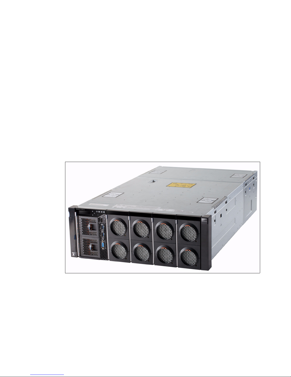
Figure 1 shows the x3850 X6 server.
Figure 1 x3850 X6 server
The x3850 X6 server has the following key characteristics:
Up to four Intel Xeon processor E7-4800 v2 or E7-8800 v2 product family processors
Up to 96 DIMM slots (24 DIMM slots per processor) for up to 6 TB of memory (using
64 GB DIMMs)
Up to 1600 MHz DDR3 memory speeds and up to 2667 MHz SMI2 link speeds
Up to 12.8 TB of eXFlash memory-channel storage
Up to eight 2.5-inch hot-swap drives or up to 16 1.8-inch hot-swap solid-state drives
(SSDs)
Support for 12 Gbps serial-attached SCSI (SAS) connectivity for the internal storage
2 Lenovo System x3850 X6 and x3950 X6 Quick Start Guide

Mezzanine LOM (ML) slot for the integrated network interface controller (NIC) functionality
(choice of dual-port 10 GbE or quad-port 1 GbE adapters)
Up to 11 PCIe 3.0 I/O slots
Internal USB port for the embedded hypervisor
Three USB ports on the front of the server, 2x USB 3.0 and 1x USB 2.0
Figure 2 shows the x3950 X6 server.
Figure 2 x3950 X6 server
The x3950 X6 server has the following key characteristics:
Up to eight Intel Xeon processor E7-8800 v2 product family processors
Up to 192 DIMM slots (24 DIMM slots per processor) for up to 12 TB of memory (using
64 GB DIMMs)
Up to 1600 MHz DDR3 memory speeds and up to 2667 MHz SMI2 link speeds
Up to 12.8 TB of eXFlash memory-channel storage
Up to 16 2.5-inch hot-swap drives or up to 30 two 1.8-inch hot-swap SSDs
Support for 12 Gbps SAS connectivity for the internal storage
Two ML slots for the integrated NIC functionality (choice of dual-port 10 GbE or quad-port
1 GbE adapters)
Up to 22 PCIe 3.0 I/O slots
Two internal USB ports for the embedded hypervisors
Six USB ports on the front of the server, 4x USB 3.0 and 2x USB 2.0
Lenovo System x3850 X6 and x3950 X6 Quick Start Guide 3
The supported operating systems for both x3850 X6 server and x3950 X6 server include:
SMI
links
MB 2
MB 1
X6 DDR3
Compute Book
QPI links
Intel
Xeon
CPU 1
MB 2
MB 1
MB 2
MB 1
MB 2
MB 1
MB 2
MB 1
DMI
links
Slot 7: PCIe 3.0 x16 (x16)
Slot 9: PCIe 3.0 x16 (x16)
MB 2
MB 1
MB 2
MB 1
MB 2
MB 1
8x USB
Serial
Management
Video
IMM2
PCIe x1
Slot 10: Mezz LOM (x8)
Slot 12: PCIe 3.0 x16 (x8)
Intel
Xeon
CPU 2
Slot 8: PCIe 3.0 x16 (x8)
Slot 11: PCIe 3.0 x16 (x8)
Intel
Xeon
CPU 4
Intel
Xeon
CPU 3
Slot 1: PCIe 3.0 x16 (x16)
Slot 2: PCIe 3.0 x8 (x8)
Slot 3: PCIe 3.0 x8 (x8)
Slot 4: PCIe 3.0 x16 (x16)
Slot 5: PCIe 2.0 x8 (x8)
Slot 6: PCIe 3.0 x16 (x16)
Storage Book
Primary I/O Book
PCIe 3.0 lanes
Full Length I/O Book
Half Length I/O Book
PCIe 3.0 lanes
Intel
I/O Hub
PCIe
switch
Microsoft Windows Server 2008 R2
Microsoft Windows Server 2012
Microsoft Windows Server 2012 R2
Red Hat Enterprise Linux 6.5+
SUSE Linux Enterprise Server 11 SP1+
VMware vSphere (ESXi) 5.1 U1+
VMware vSphere (ESXi) 5.5
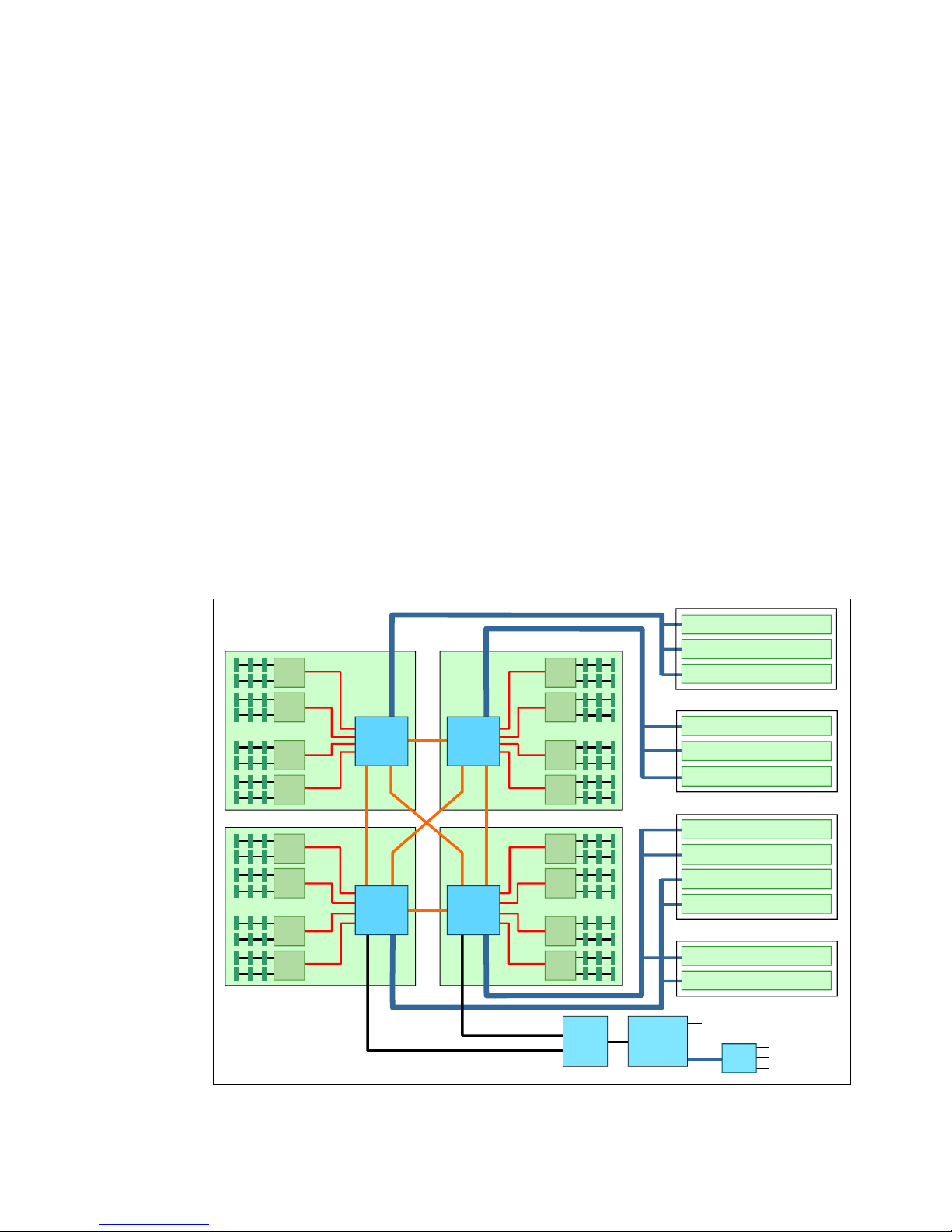
Architecture
To ensure proper function of the X6 server, the system should be configured correctly at the
time of purchase. The block diagram of the system in Figure 3 shows that proper memory and
I/O placement is critical for optimal performance. With the move to the Intel Ivy Bridge
processors in the X6 platform, the I/O is now directly attached to the processors. Additionally,
memory population rules have become more complex because each channel now has three
DIMMs and different memory modes.
There are a few general preferred practices in regards to configuring the system. Memory
should be installed in quantities of eight DIMMs per CPU for optimal performance and to
avoid any potential issues with memory installation order interfering with the memory mode
chosen. For best I/O performance, install the correct amount of adapters so that as many
processors as possible have a direct connection to I/O.
Figure 3 x3850 X6 system architecture
4 Lenovo System x3850 X6 and x3950 X6 Quick Start Guide
Memory subsystem
Intel Xeon processor
DIMM
Memory
controller
DIMM
DIMM
Memory
controller
DIMM
DIMM
DIMM
DIMM
DIMM
DIMM
DIMM
DIMM
DIMM
DIMM
DIMM
DIMM
DIMM
DIMM
DIMM
DIMM
DIMM
DIMM
DIMM
DIMM
DIMM
Memory
buffer
Memory
buffer
Memory
buffer
Memory
buffer
Data 1Data 0
Intel Xeon processor
DIMM
Memory
controller
DIMM
DIMM
Memory
controller
DIMM
DIMM
DIMM
DIMM
DIMM
DIMM
DIMM
DIMM
DIMM
DIMM
DIMM
DIMM
DIMM
DIMM
DIMM
DIMM
DIMM
DIMM
DIMM
DIMM
DIMM
Memory
buffer
Memory
buffer
Memory
buffer
Memory
buffer
Data
Lockstep
channel
SMI2
links
DDR3
links
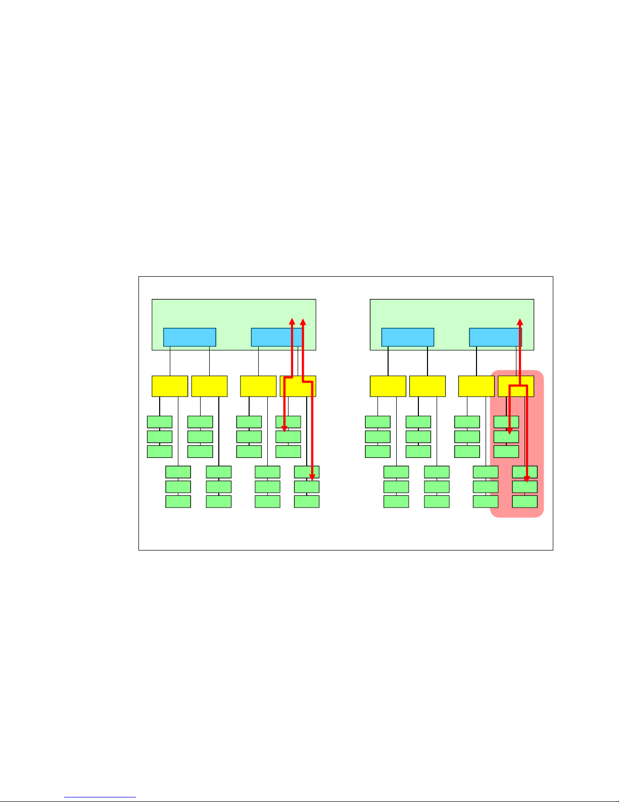
Memory performance mode Memory RAS mode
The memory subsystem can operate in one of the following modes:
Independent (Performance) mode
Lockstep (RAS) mode
In
Performance mode, each channel on an SMI is addressed independently, essentially
providing the ability to run two transactions at once. In
spread across both channels on an SMI is addressed simultaneously. Lockstep mode
provides higher memory frequency and memory reliability (Double Device Data Correction
+1 bit) but at the expense of higher memory bandwidth. Conversely, Independent mode
provides higher memory bandwidth at the cost of advanced memory RAS features and
memory frequency (Single Device Data Correction only).
Figure 4 shows the two memory modes.
Lockstep mode, a pair of DIMMs
Figure 4 Memory modes: Performance mode (left) and RAS mode (right)
Lenovo System x3850 X6 and x3950 X6 Quick Start Guide 5
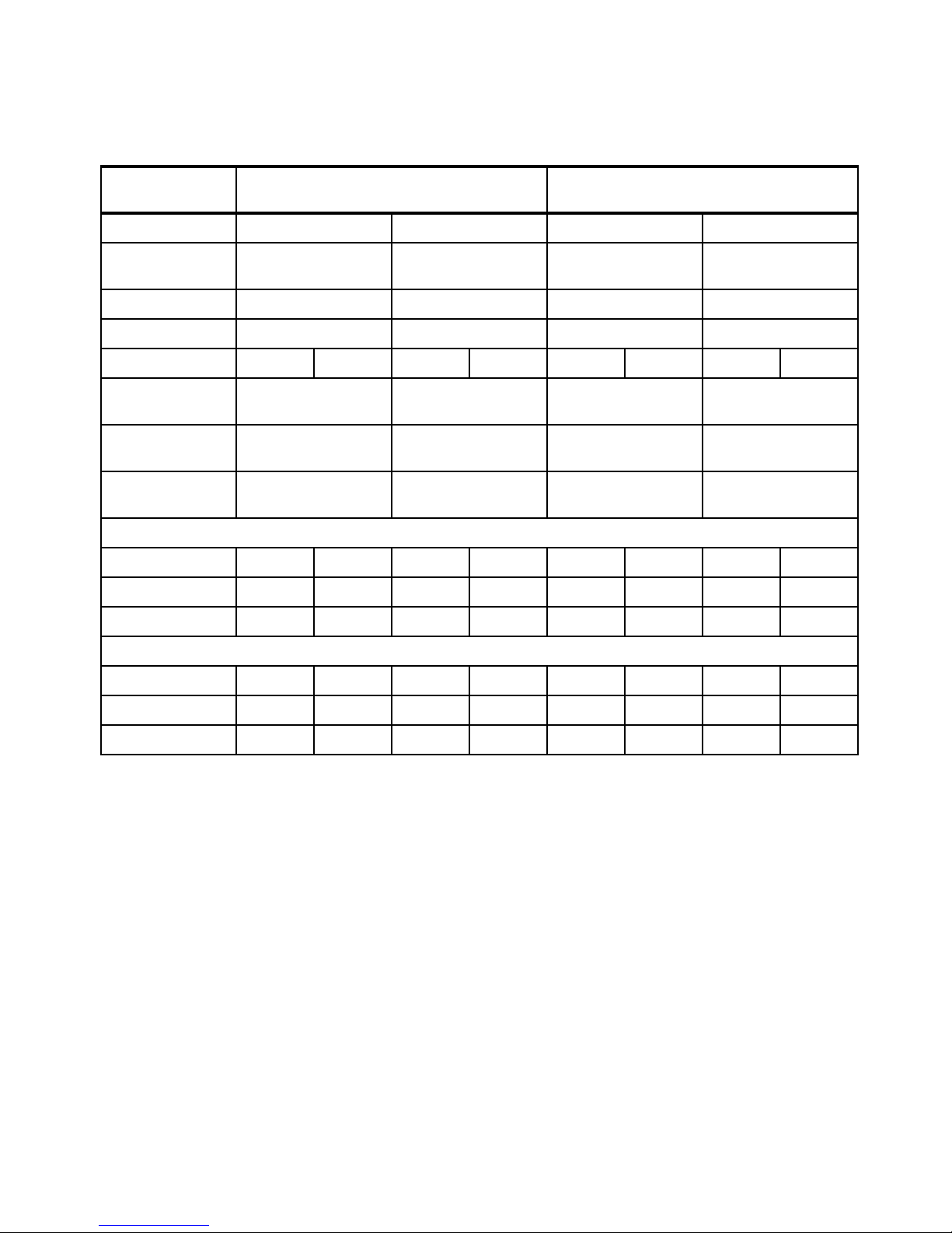
Table 1 shows the characteristics of the supported DIMMs and the memory speeds.
Table 1 Characteristics of the supported DIMMs and the memory speeds
DIMM
Specification
Ranks Single-rank DIMM Dual-rank DIMM 4R LR-DIMM 8R LR-DIMM
Part number 00D5024 (4 GB)
00D5036 (8 GB)
Rated speed 1600 MHz 1600 MHz 1600 MHz 1333 MHz
Rated voltage 1.35 V 1.35 V 1.35 V 1.35 V
Operating voltage 1.35 V 1.5 V 1.35 V 1.5 V 1.35 V 1.5 V 1.35 V 1.5 V
Maximum quantity
supported
Maximum DIMM
capacity
Maximum memory
capacity
Maximum operating speed: Independent (Performance) mode
1 DIMM/channel
2 DIMMs/channel 1333 MHz 1333 MHz 1333 MHz 1333 MHz 1333 MHz 1333 MHz 1333 MHz 1333 MHz
3 DIMMs/channel 1066 MHz 1333 MHz 1066 MHz 1333 MHz 1333 MHz 1333 MHz 1333 MHz 1333 MHz
1333 MHz 1333 MHz 1333 MHz 1333 MHz 1333 MHz 1333 MHz 1333 MHz 1333 MHz
96 96 96 96
8 GB 16 GB 32 GB 64 GB
768 GB 1.5 TB 3 TB 6 TB
RDIMM LR-DIMM
46W0672 (16 GB) 46W0676
(32 GB)
46W0741
(64 GB)
Maximum operating speed: Lockstep (RAS) mode
1 DIMM/channel 1333 MHz 1600 MHz 1333 MHz 1600 MHz 1333 MHz 1600 MHz 1333 MHz 1333 MHz
2 DIMMs/channel 1333 MHz 1600 MHz 1333 MHz 1600 MHz 1333 MHz 1600 MHz 1333 MHz 1333 MHz
3 DIMMs/channel 1066 MHz 1333 MHz 1066 MHz 1333 MHz 1333 MHz 1333 MHz 1333 MHz 1333 MHz
6 Lenovo System x3850 X6 and x3950 X6 Quick Start Guide
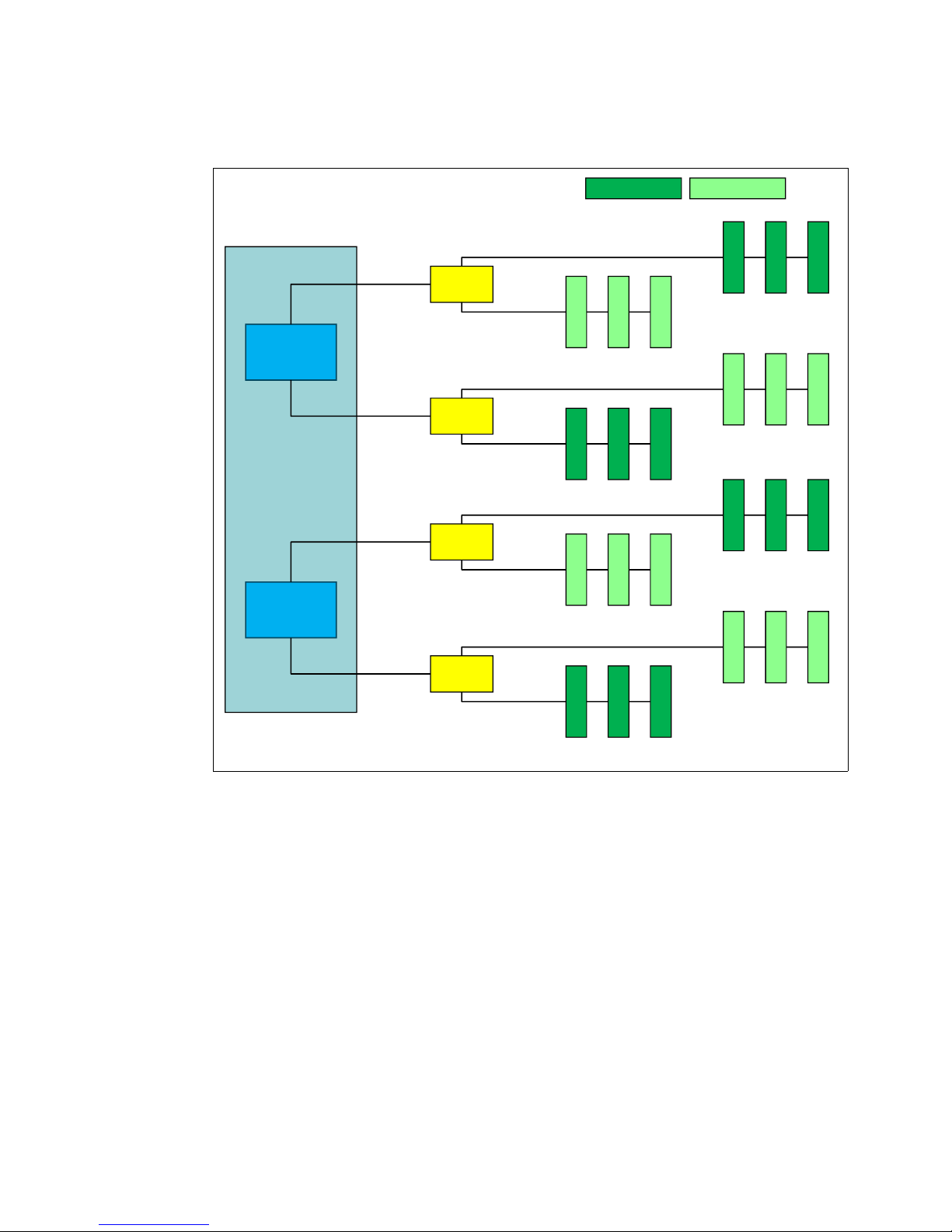
Figure 5 shows the Intel Xeon E7 memory controller architecture. Note that memory is
Intel
Xeon
processor
Memory
controller 1
Memory
buffer 1
DIMM 19
DIMM 21
DIMM 20
Slot 2Slot 1Slot 0
Slot 2Slot 1Slot 0
DIMM 1
DIMM 3
DIMM 2
Memory
controller 2
Memory
buffer 2
DIMM 6
DIMM 4
DIMM 5
Slot 2Slot 1Slot 0
Slot 2Slot 1Slot 0
DIMM 24
DIMM 22
DIMM 23
Memory
buffer 3
DIMM 16
DIMM 18
DIMM 17
Slot 2Slot 1Slot 0
Slot 2Slot 1Slot 0
DIMM 10
DIMM 12
DIMM 11
Memory
channel 0
Memory
channel 1
Memory
channel 2
Memory
channel 3
Memory
buffer 0
DIMM 9
DIMM 7
DIMM 8
Front DIMMs
Slot 2Slot 1Slot 0
Slot 2Slot 1Slot 0
DIMM 15
DIMM 13
DIMM 14
DDR3 ch 0
DDR3 ch 1
DDR3 ch 0
DDR3 ch 1
DDR3 ch 0
DDR3 ch 1
DDR3 ch 0
DDR3 ch 1
Back DIMMs
populated from the furthest DIMM (Slot 0) to the closest DIMM slot (Slot 2).
Figure 5 Xeon E7 memory controller architecture
Lenovo System x3850 X6 and x3950 X6 Quick Start Guide 7
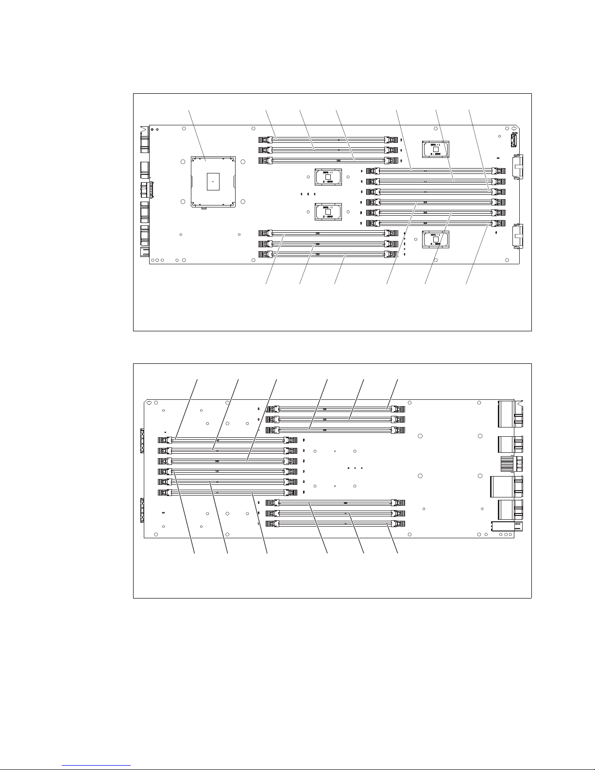
Figure 6 and Figure 7 show the central processing unit (CPU) board layout.
DIMM 1 DIMM 2 DIMM 3
DIMM 4 DIMM 5 DIMM 6 DIMM 10 DIMM 11 DIMM 12
DIMM 7 DIMM 8 DIMM 9Microprocessor
(Left side of board)
DIMM 24
DIMM 23
DIMM 22
DIMM 19DIMM 20
DIMM 21
DIMM 15
DIMM 14
DIMM 13
DIMM 18
DIMM 17
DIMM 16
(Right side of board)
Figure 6 CPU layout (left side of board)
8 Lenovo System x3850 X6 and x3950 X6 Quick Start Guide
Figure 7 CPU layout (right side of board)
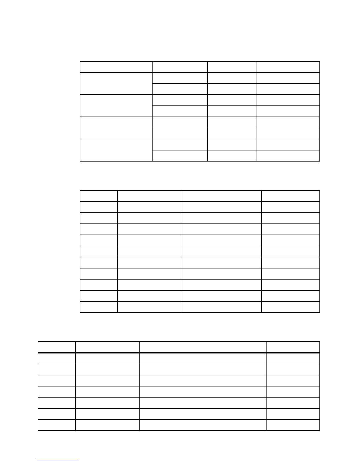
Table 2 shows the memory layout.
Table 2 Memory layout
CPU memory channel DDR3 channel DIMM number DDR3 slot number
Channel 0 DDR3 Channel 0 9, 8, 7 0, 1, 2
DDR3 Channel 1 15, 14, 13 0, 1, 2
Channel 1 DDR3 Channel 0 19, 20, 21 0, 1, 2
DDR3 Channel 1 1, 2, 3 0, 1, 2
Channel 2 DDR3 Channel 0 6, 5, 4 0, 1, 2
DDR3 Channel 1 24, 23, 22 0, 1, 2
Channel 3 DDR3 Channel 0 16, 17, 18 0, 1, 2
DDR3 Channel 1 10, 11, 12 0, 1, 2
Table 3 shows the Independent mode population sequence.
Table 3 Independent mode population sequence
Installation Population sequence DIMM number DDR3 slot number
1st 1 SMI0, Channel0, Slot0 Front
2nd 2 SMI2, Channel0, Slot0 Front
3rd 3 SMI1, Channel1, Slot0 Front
4th 4 SMI3, Channel1, Slot0 Front
5th 5 SMI0, Channel1, Slot0 Back
6th 6 SMI2, Channel1, Slot0 Back
7th 7 SMI1, Channel0, Slot0 Back
8th 8 SMI3, Channel0, Slot0 Back
... 9 - 16 Repeat order, move to Slot1 Four front, four back
... 17 - 24 Repeat order, move to Slot 2 Four front, four back
Table 4 shows the Lockstep (RAS) mode population sequence.
Table 4 Lockstep (RAS) mode population sequence
Installation Population sequence Controller location Physical location
1st 1 & 2 SMI0, Channel0, Slot0 & SMI0, Channel1, Slot0 Front & back
2nd 3 & 4 SMI2, Channel0, Slot0 & SMI2, Channel1, Slot0 Front & back
3rd 5 & 6 SMI1, Channel1, Slot0 & SMI1, Channel0, Slot0 Front & back
4th 7 & 8 SMI3, Channel1, Slot0 & SMI3, Channel0, Slot0 Front & back
5th 9 & 10 Repeat order, move to Slot1 Front & back
6th 11 & 12 Repeat order, move to Slot1 Front & back
7th 13 & 14 Repeat order, move to Slot1 Front & back
Lenovo System x3850 X6 and x3950 X6 Quick Start Guide 9
Installation Population sequence Controller location Physical location
8th 15 & 16 Repeat order, move to Slot1 Front & back
... 18 - 24 Repeat order, move to Slot2 Front & back
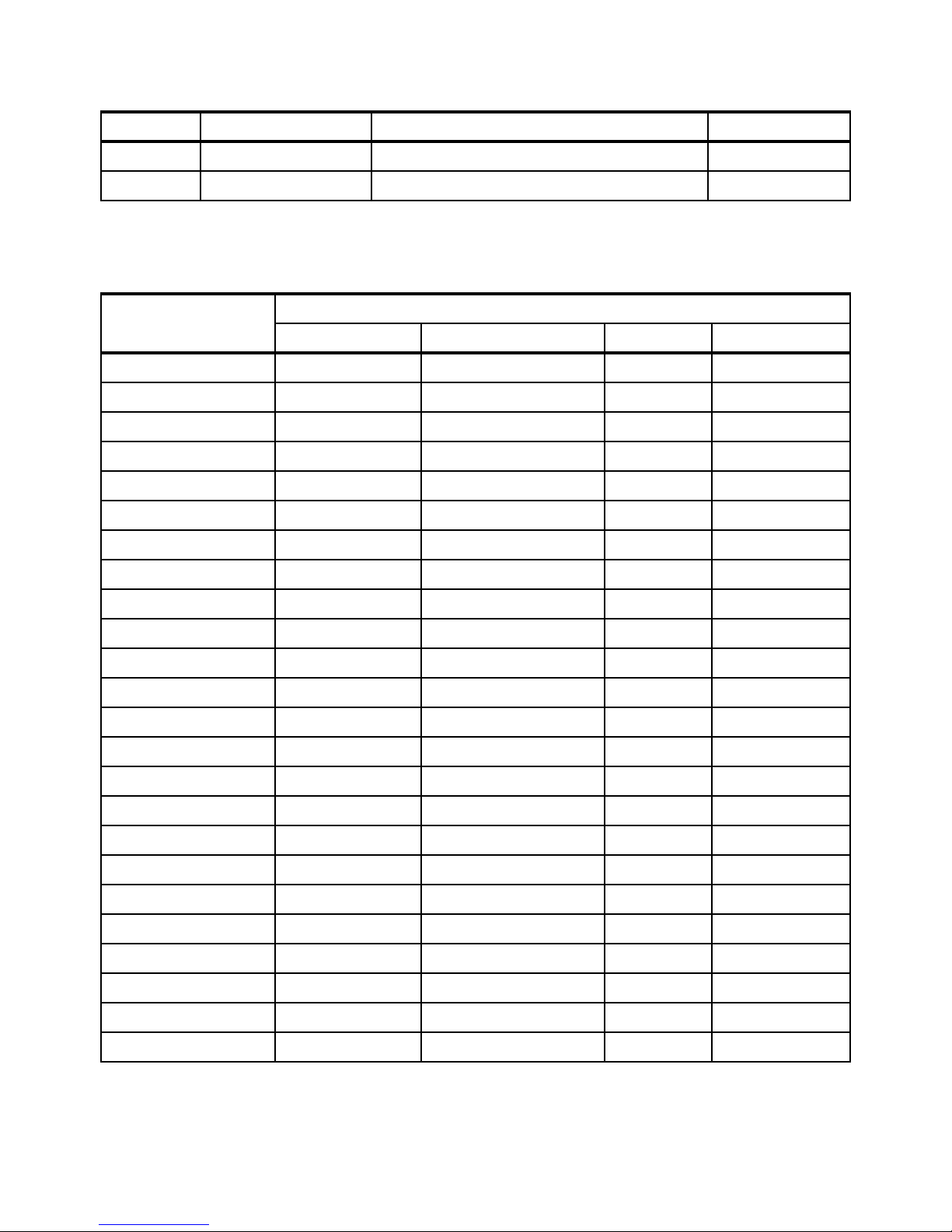
Table 5 shows the memory population order for both Independent (Performance) mode and
Lockstep (RAS) mode.
Table 5 Memory population order for both Independent (Performance) mode and Lockstep (RAS)
DIMM installation order DIMM slots
Performance mode Performance + mirroring RAS mode RAS + mirroring
1 DIMM 9 DIMM 9, 19 DIMM 9, 15 DIMM 1, 9, 15, 19
2 DIMM 6 DIMM 6, 16 DIMM 6, 24 DIMM 6, 10, 16, 24
3 DIMM 1 DIMM 1, 15 DIMM 1, 19 DIMM 2, 8, 14, 20
4 DIMM 10 DIMM 10, 24 DIMM 10, 16 DIMM 5, 11, 17, 23
5 DIMM 15 DIMM 8, 20 DIMM 8, 14 DIMM 3, 7, 13, 21
6 DIMM 24 DIMM 5, 17 DIMM 5, 23 DIMM 4, 12, 18, 22
7 DIMM 19 DIMM 2, 14 DIMM 2, 20 Not applicable
8 DIMM 16 DIMM 11, 23 DIMM 11, 17 ....
9 DIMM 8 DIMM 7, 21 DIMM 7, 13
10 DIMM 5 DIMM 4, 18 DIMM 4, 22
11 DIMM 2 DIMM 3, 13 DIMM 3, 21
12 DIMM 11 DIMM 12, 22 DIMM 12, 18
13 DIMM 14 Not applicable Not applicable
14 DIMM 23 .... ....
15 DIMM 20
16 DIMM 17
17 DIMM 7
18 DIMM 4
19 DIMM 3
20 DIMM 12
21 DIMM 13
22 DIMM 22
23 DIMM 21
24 DIMM 18
10 Lenovo System x3850 X6 and x3950 X6 Quick Start Guide

Important notes
Keep in mind the following important aspects of the memory subsystem when setting up and
using your server:
The optimal memory configuration is to install DIMMs in quantities of eight per CPU. This
configuration ensures that every channel on every memory buffer is populated.
Additionally, it ensures that no matter what memory mode is chosen, the system functions
correctly.
Proper memory population rules for DIMMs include:
– Higher capacity (ranked) DIMMs must be installed first. Follow the population
– The server supports a maximum of eight ranks (octal-rank) per DDR3 channel. Note
– The server supports 1.35-volt (low-voltage) registered DIMMs, depending on the
– RDIMMs and LR-DIMMs cannot be mixed in the same system. Make sure to populate
– A minimum of one DIMM must be installed for each Compute Book. Depending on the
The default memory mode for the X6 system is Lockstep, which is important for those
scenarios where less than the optimal number of DIMMs per processor are installed.
Always be sure to properly configure the memory mode in Unified Extensible Firmware
Interface (UEFI) before changing the DIMM installation order, but prior to a reboot, for this
configuration to take effect.
sequence for the appropriate mode.
that LR-DIMMs might exceed eight ranks per channel through rank multiplication.
memory configuration settings in the Setup utility. The server can also operate at
1.5-volt.
the largest DIMMs in the channel first to enable optimal performance.
• RDIMMs are available in 4 GB, 8 GB, and 16 GB.
• LR-DIMMs are available in 32 GB and 64 GB.
memory mode (for example, Lockstep), this configuration might not be sufficient for
operation.
When not fully populating system memory according to preferred practices, changing the
memory mode can cause the system to fail to boot. The memory population label on the
CPU book is for Performance mode. Lockstep mode DIMMs should be installed in pairs.
You can use the Advanced Settings Utility™ (ASU) tool to remotely flip the memory mode.
For example:
asu64 Memory.MemoryMode Independent OR ./asu64 Memory.MemoryMode Lockstep
The maximum operating speed of the server's memory is determined by the slowest
DIMM in the server.
If swapping out a failed DIMM, make sure you move the DIMM to a different SMI and
re-enable the failed DIMM slot.
If planning to install eXFlash DIMMs, note that eXFlash DIMMs are RDIMMs and,
therefore, cannot be used with either the 32 GB or 64 GB LR-DIMMs.
No more than one eXFlash DIMM per channel is supported, and at least one RDIMM must
already be present in the same channel as the eXFlash DIMM that it will be installed in.
Lenovo System x3850 X6 and x3950 X6 Quick Start Guide 11
 Loading...