

Page 1
Page 2

Page 3

ThinkStation
Hardw are Installation an d Replacement
Guid e
Page 4

Note
Before using this information and the product it supports, be sure to read and understand the Safety and Warranty Guide for
this product and “Notices,” on page 49.
Second Edition (July 2008)
© Copyright Lenovo 2005, 2008.
Portions © Copyright International Business Machines Corporation 2005.
All rights reserved.
LENOVO products, data, computer software, and services have been developed exclusively at private expense and
are sold to governmental entities as commercial items as defined by 48 C.F.R. 2.101 with limited and restricted
rights to use, reproduction and disclosure.
LIMITED AND RESTRICTED RIGHTS NOTICE: If products, data, computer software, or services are delivered
pursuant a General Services Administration ″GSA″ contract, use, reproduction, or disclosure is subject to restrictions
set forth in Contract No. GS-35F-05925.
Page 5

Contents
Figures . . . . . . . . . . . . . . .v
Chapter 1. Important safety information 1
Chapter 2. Overview . . . . . . . . .3
Additional information resources . . . . . . .3
Handling static-sensitive devices . . . . . . . .4
Locations . . . . . . . . . . . . . . .5
Locating controls and connectors on the front of
your computer . . . . . . . . . . . . .5
Locating connectors on the rear of your computer 6
Locating internal components . . . . . . . .8
Identifying parts on the system board . . . . .9
Chapter 3. Installing options and
replacing hardware . . . . . . . . .11
Installing external options . . . . . . . . .11
Installing internal options . . . . . . . . .12
Opening the cover . . . . . . . . . . .12
Removing the front bezel . . . . . . . . .14
Accessing system board components and drives 15
Installing internal drives . . . . . . . . .17
Erasing a lost or forgotten password (clearing
CMOS) . . . . . . . . . . . . . . . .23
Replacing the battery . . . . . . . . . . .24
Replacing the power supply assembly . . . . .25
Replacing an adapter card . . . . . . . . .28
Replacing the heat sink . . . . . . . . . .30
Replacing a hard disk drive . . . . . . . . .31
Replacing the optical drive . . . . . . . . .33
Replacing the diskette drive or optional card reader 34
Installing or replacing a memory module . . . .36
Replacing the fan assembly . . . . . . . . .37
Replacing the internal speaker . . . . . . . .39
Replacing the keyboard . . . . . . . . . .41
Replacing the mouse . . . . . . . . . . .42
Chapter 4. Completing the parts
replacement . . . . . . . . . . . .43
Updating (flashing) BIOS from a diskette or
CD-ROM . . . . . . . . . . . . . . .43
Recovering from a POST/BIOS update failure . . .45
Obtaining device drivers . . . . . . . . . .45
Chapter 5. Security features . . . . .47
Locking devices . . . . . . . . . . . . .47
Password protection . . . . . . . . . . .48
Appendix. Notices . . . . . . . . . .49
Television output notice . . . . . . . . . .50
Trademarks . . . . . . . . . . . . . .50
Index . . . . . . . . . . . . . . .51
© Lenovo 2005, 2008. Portions © IBM Corp. 2005. iii
Page 6

iv ThinkStation Hardware Installation and Replacement Guide
Page 7

Figures
1. Controls and connectors . . . . . . . . .5
2. Connector locations . . . . . . . . . .6
3. Component locations . . . . . . . . . .8
4. System board parts locations . . . . . . .9
5. Removing the cover . . . . . . . . . .13
6. Removing the front bezel . . . . . . . .14
7. Accessing the system board . . . . . . .16
8. Drive bay locations . . . . . . . . . .18
9. Installing an optical drive . . . . . . . .19
10. Installing an optical drive . . . . . . . .20
11. Installing a new drive . . . . . . . . .22
12. Battery removal . . . . . . . . . . .24
13. Battery installation . . . . . . . . . .24
14. System-board connectors . . . . . . . .25
15. Replacing the power supply retaining screws 26
16. Removing the power supply . . . . . . .27
17. Installing an adapter card . . . . . . . .29
18. Removing the heat sink . . . . . . . .30
19. Removing the hard disk drive . . . . . .32
20. Replacing the hard disk drive . . . . . .33
21. Removing the diskette drive or optional card
reader drive . . . . . . . . . . . .34
22. Removing the diskette drive or optional card
reader drive . . . . . . . . . . . .35
23. Replacing the diskette drive or optional card
reader drive . . . . . . . . . . . .35
24. Memory modules . . . . . . . . . .36
25. Removing a memory module . . . . . .37
26. Installing a memory module . . . . . . .37
27. Removing the fan assembly . . . . . . .38
28. Removing the internal speaker . . . . . .39
29. Keyboard connectors, standard and USB 41
30. Replacing a mouse . . . . . . . . . .42
31. Integrated cable lock . . . . . . . . .47
© Lenovo 2005, 2008. Portions © IBM Corp. 2005. v
Page 8

vi ThinkStation Hardware Installation and Replacement Guide
Page 9

Chapter 1. Important safety information
CAUTION:
Before using this manual, it is important that you read and understand all the
related safety information for this product. Refer to the Safety and Warranty Guide
that you received with this product for the latest safety information. Reading
and understanding the safety information reduces the risk of personal injury
and damage to your product.
If you no longer have a copy of the Safety and Warranty Guide, you can obtain one
online from the Lenovo® Support Web site at:
http://www.lenovo.com/support/
© Lenovo 2005, 2008. Portions © IBM Corp. 2005. 1
Page 10

2 ThinkStation Hardware Installation and Replacement Guide
Page 11

Chapter 2. Overview
This guide contains information about replacing Customer Replaceable Units
(CRUs).
This guide does not include procedures for all parts. It is expected that cables,
switches, and certain mechanical parts be replaced by trained service personnel
without the need for step-by-step procedures.
Note: Use only parts provided by Lenovo.
This guide contains instructions for installing and or replacing the following parts:
v Battery
v Front Bezel
v Power supply
v Heat sink
v Hard disk drive
v Optical drive
v Diskette drive or card reader
v Memory modules
v Fan assembly
v Internal speaker
v Keyboard
v Mouse
Additional information resources
If you have Internet access, the most up-to-date information for your computer is
available from the World Wide Web.
You can find:
v CRU removal and installation information
v CRU removal and installation videos
v Publications
v Troubleshooting information
v Parts information
v Downloads and drivers
v Links to other useful sources of information
v Support phone list
access this information, go to:
To
http://www.lenovo.com/support/
© Lenovo 2005, 2008. Portions © IBM Corp. 2005. 3
Page 12

Handling static-sensitive devices
Do not open the static-protective package containing the new part until the
defective part has been removed from the computer and you are ready to install
the new part. Static electricity, although harmless to you, can seriously damage
computer components and parts.
When you handle parts and other computer components, take these precautions to
avoid static-electricity damage:
v Limit your movement. Movement can cause static electricity to build up around
you.
v Always handle parts and other computer components carefully. Handle
adapters, memory modules, system boards, and microprocessors by the edges.
Never touch any exposed circuitry.
v Prevent others from touching the parts and other computer components.
v Before you replace a new part, touch the static-protective package containing the
part to a metal expansion-slot cover or other unpainted metal surface on the
computer for at least two seconds. This reduces static electricity in the package
and your body.
v When possible, remove the new part from the static-protective packaging, and
install it directly in the computer without setting the part down. When this is
not possible, place the static-protective package that the part came in on a
smooth, level surface and place the part on it.
v Do not place the part on the computer cover or other metal surface.
4 ThinkStation Hardware Installation and Replacement Guide
Page 13
Locations
Locating controls and connectors on the front of your computer
This section contains illustrations to help locate the various connectors, controls,
and components of the computer.
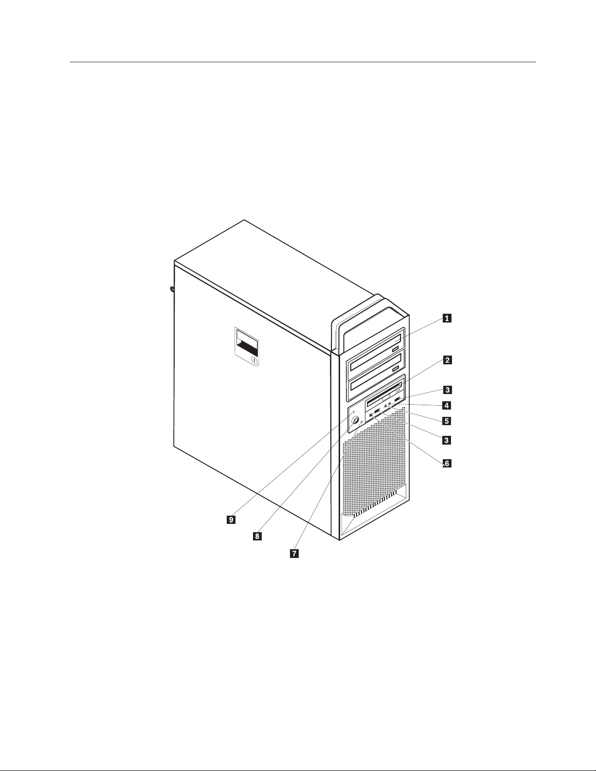
Figure 1 shows the location of the controls and connectors on the front of your
computer.
Note: Not all computer models will have the following controls and connections.
Figure 1. Controls and connectors
1 Optical drive (some models) 6 IEEE 1394 connector
2 3.5 Diskette drive or card reader
7 Hard drive activity light
(some models)
3 USB connectors (2) 8 Power button
4 Microphone connector 9 Power-on indicator
5 Headphone connector
Chapter 2. Overview 5
Page 14
Locating connectors on the rear of your computer
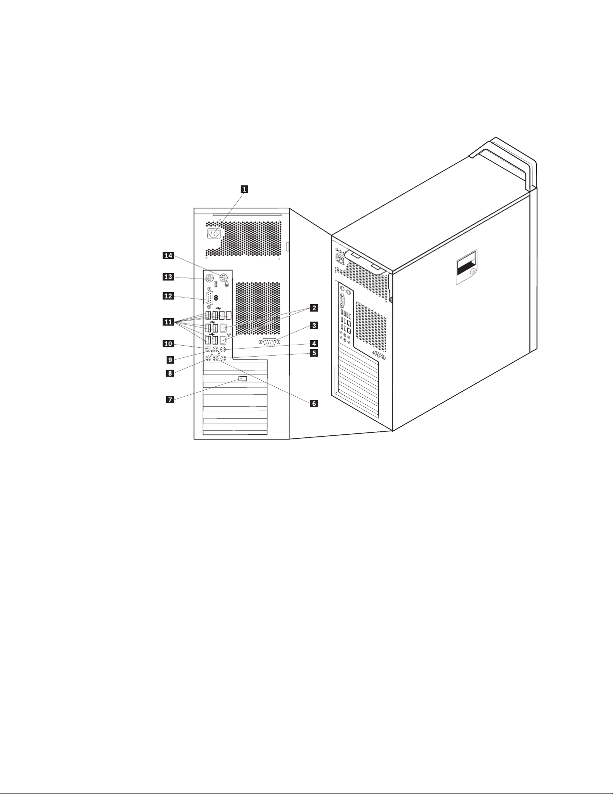
Figure 2 shows the location of connectors on the rear of your computer. Some
connectors on the rear of your computer are color-coded to help you determine
where to connect the cables on your computer.
Figure 2. Connector locations
1 Power cord connector 8 Microphone connector
2 Ethernet connector 9 Audio line-out connector, rear speakers
3 Serial connector (some models) 10 SPDIF connector
4 Audio line-out sub/center
11 USB connectors (8)
connector
5 Audio line-in connector 12 Serial connector
6 Audio line-out front speakers
13 Keyboard connector
connector
7 Video connector (some models) 14 Mouse connector
6 ThinkStation Hardware Installation and Replacement Guide
Page 15

Connector Description
USB connector Used to attach a device that requires a Universal Serial Bus
(USB) connection, such as a USB keyboard, USB mouse, USB
scanner or USB printer. If you have more than eight USB
devices, you can purchase a USB hub, which you can use to
connect additional USB devices.
Ethernet connector Used to attach an Ethernet cable for a local area network
(LAN).
Note: To operate the computer within FCC Class B limits, use
a Category 5 Ethernet cable.
Serial connector Used to attach an external modem, serial printer, or other
devices that use a 9-pin serial connector.
Parallel connector Used to attach a parallel printer, parallel scanner, or other
devices that use a 25-pin parallel connector.
Audio line-in connector Used to receive audio signals from an external audio device,
such as a stereo system. When you attach an external audio
device, a cable is connected between the audio line-out
connector of the device and the audio line-in connector of the
computer.
Audio line-out connector Used to send audio signals from the computer to external
devices, such as powered stereo speakers (speakers with
built-in amplifiers), headphones, multimedia keyboards, or the
audio line-in connector on a stereo system or other external
recording device.
SPDIF connector Used to send digital audio signals from a computer to an
external device (such as an amplifier/receiver), through an
optical cable.
Chapter 2. Overview 7
Page 16
Locating internal components
To open the computer cover, see “Opening the cover” on page 12.
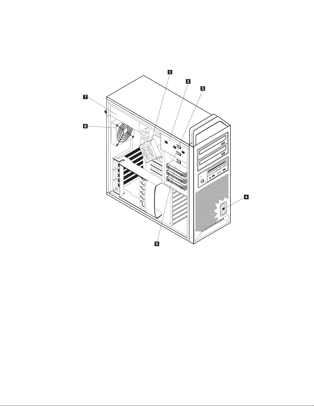
Figure 3 shows the location of the components in your computer.
Figure 3. Component locations
1 Microprocessor and heat sink 5 Hard disk drive
2 Optical drive (such as a CD or
DVD drive)
3 3.5 inch diskette drive or card reader 7 Power supply assembly
4 Internal speaker
8 ThinkStation Hardware Installation and Replacement Guide
6 Rear fan assembly
Page 17
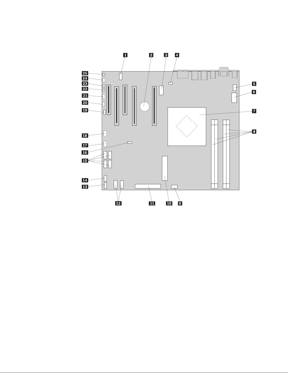
Identifying parts on the system board
Figure 4 shows the location of parts on the system board.
Figure 4. System board parts locations
1 COM2 14 Front USB connector
2 Battery 15 S ATA connectors (4)
3 12 volt power connector,
16 Clear CMOS/Recovery jumper
graphics
4 Rear fan connector 17 Front adapter fan connector
5 Microprocessor heat sink fan
18 IEEE 1394 Connector
connector
6 Microprocessor 12 V power
19 SAS LED connector
connector
7 Microprocessor and heat sink 20 Auxiliary LEDs connector
8 Memory connectors (4) 21 Front panel connector
9 Front hard disk drive fan
22 Cover tamper switch connector
connector
10 24- pin system power connector 23 Ambient temperature connector
11 Diskette drive connector 24 Front audio connector
12 SATA connectors (2) 25 Internal speaker
13 Auxiliary USB connector
Chapter 2. Overview 9
Page 18

10 ThinkStation Hardware Installation and Replacement Guide
Page 19
Chapter 3. Installing options and replacing hardware
This chapter is an introduction to the features and options that are available for
your computer. You can expand the capabilities of your computer by adding
memory, adapters, or drives. When installing an option, use these instructions
along with the instructions that come with the option.
Attention
Do not open your computer or attempt any repair before reading the “Important safety
information” in the Safety and Warranty Guide that was included with your computer. To
obtain a copy of the Safety and Warranty Guide, go to the Support Web site at:
http://www.lenovo.com/support/
Note: Use only parts provided by Lenovo.
Installing external options
External speakers, a printer, or a scanner can be connected to your computer. For
some external options, you must install additional software in addition to making
the physical connection. When adding an external option, see “Locating connectors
on the rear of your computer” on page 6 and “Locating controls and connectors on
the front of your computer” on page 5 to identify the required connector, and then
use the instructions that are included with the option to help you make the
connection and install any software or device drivers that are required for the
option.
© Lenovo 2005, 2008. Portions © IBM Corp. 2005. 11
Page 20

Installing internal options
Important
Read “Handling static-sensitive devices” on page 4 before opening the
computer cover.
Opening the cover
To open the computer cover:
1. Remove any media (diskettes, CDs, or tapes) from the drives, shut down your
operating system. Turn off all attached devices. Turn off the computer.
Important
Turn off the computer and wait 3 to 5 minutes to let the computer cool
before opening the computer cover.
2. Unplug all power cords from electrical outlets.
3. Disconnect the cables attached to the computer. This includes power cords,
input/output (I/O) cables, and any other cables that are connected to the
computer. See “Locating controls and connectors on the front of your
computer” on page 5 and “Locating connectors on the rear of your computer”
on page 6.
4. Remove any locking devices, such as a cable lock or padlock that secures the
computer cover. See Chapter 5, “Security features,” on page 47.
12 ThinkStation Hardware Installation and Replacement Guide
Page 21

5. Disengage the cover latch 1, and open the cover. Remove the cover and place
it on a flat surface.
Figure 5. Removing the cover
To replace the cover:
1. Align the cover with the chassis.
2. Close the cover.
3. Engage the cover latch.
4. Check to be sure the cover is latched.
Chapter 3. Installing options and replacing hardware 13
Page 22

5. Secure the cover using your locking device.
Removing the front bezel
To remove the front bezel:
1. Remove the cover, see “Opening the cover” on page 12.
2. Disengage the bezel latches 1, one at a time while rotating the bezel away
from the computer just enough to keep the latches disengaged.
3. Lay the front bezel on a flat surface.
4. Reverse these steps to replace the front bezel.
Figure 6. Removing the front bezel
14 ThinkStation Hardware Installation and Replacement Guide
Page 23

Accessing system board components and drives
To access system board components:
1. Open the computer cover. See “Opening the cover” on page 12.
2. Unlatch and open the adapter card retainer.
3. Remove the hard disk drive fan and bracket (some models).
4. Take note of the location of all cable connections on the adapter cards. It will be
necessary to reconnect them properly when replacing the cards.
5. Disconnect all cables connected to the adapter cards. See “Identifying parts on
the system board” on page 9.
6. Remove the card retaining screw, if one is used.
7. Release the card support retaining latches. Grasp the adapter card and pull the
card out of the slot. See “Replacing an adapter card” on page 28 for more
information.
The card is a tight fit, so it might be necessary to remove each side a
Note:
little at a time until the card is removed from the card slot.
Chapter 3. Installing options and replacing hardware 15
Page 24

Figure 7. Accessing the system board
16 ThinkStation Hardware Installation and Replacement Guide
Page 25

What to do next:
v To work with another option, go to the appropriate section.
v To complete the installation, go to Chapter 4, “Completing the parts
replacement,” on page 43.
Installing internal drives
This section provides information and instructions for installing and removing
internal drives.
Internal drives are devices that your computer uses to read and store data. You can
add drives to your computer to increase storage capacity and to enable your
computer to read other types of media. Some of the types of drives that are
available for your computer are:
v Serial Advanced Technology Attachment ( S ATA ) hard disk drives
v SATA optical drives, such as CD drives or DVD drives
v Removable media drives
Internal
drives are installed in bays. In this book, the bays are referred to as bay 1,
bay 2, and so on.
When you install an internal drive, it is important to note the type and size of
drive that you can install in each bay. Also, it is important to correctly connect the
internal drive cables to the installed drive.
Drive specifications
Your computer comes with the following factory-installed drives:
v An optical drive in bay 1
v A blank bay for expansion or optional optical drive
v A 3.5-inch diskette drive or a card reader in bay 3 (some models)
bay that does not have a drive installed has a static shield and bay panel
Any
installed.
Figure 8 on page 18 shows the location of the drive bays.
Chapter 3. Installing options and replacing hardware 17
Page 26

Figure 8. Drive bay locations
The following list describes the types and size of drives that you can install in each
bay:
1 Bay 1 - Maximum height: 43.0 mm (1.7 inch) Optical drives, such as CD drive or
DVD drive (preinstalled in some
models)
2 Bay 2 - Maximum height: 43.0 mm (1.7 inch) Optional drives such as CD drive or
DVD drive (preinstalled in some
models)
3 Bay 3 - Maximum height: 26.1 mm (1.0 inch) 3.5-inch diskette drive
card reader (preinstalled in some
models)
4 Bay 4 Hard disk drives (preinstalled)
18 ThinkStation Hardware Installation and Replacement Guide
Page 27

Installing a drive for bay 1
To install the optical drive for bay 1:
1. Open the computer cover. See “Opening the cover” on page 12.
2. Remove the front bezel. See “Removing the front bezel” on page 14.
Note: On the inside of the front bezel where the drive is to be located there is a
drive adapter plate for installing new drive. Remove the drive adapter plate
and use it to install the drive.
3. Remove the plastic drive cover from the bezel.
4. For drive bay one, remove the static shield (for bay one the static shield just
pulls out).
5. Install the adapter plate on the left side of the drive to be installed.
6. Slide the drive into the bay until it locks into position.
Figure 9. Installing an optical drive
7. Connect the drive cables.
8. Install the front bezel.
What to do next:
v To work with another option, go to the appropriate section.
v To complete the installation, go to Chapter 4, “Completing the parts
replacement,” on page 43.
Chapter 3. Installing options and replacing hardware 19
Page 28

Installing a drive for bay 2
To install the optical drive for bay 2:
1. Open the computer cover. See “Opening the cover” on page 12.
2. Remove the front bezel. See “Removing the front bezel” on page 14.
Note: On the inside of the front bezel where the drive is to be located there is a
drive adapter plate. If there is no drive installed there are drive adapter plates
for each drive. Remove the drive adapter plate and use it to install the drive.
3. Remove the plastic drive cover from the bezel.
4. For drive bay two, remove the static shield (for bay two the static shield just
pulls out).
5. Install the adapter plate on the left side of the drive to be installed.
6. Slide the drive into the bay until it locks into position.
Figure 10. Installing an optical drive
7. Connect the drive cables.
8. Install the front bezel.
What to do next:
v To work with another option, go to the appropriate section.
v To complete the installation, go to Chapter 4, “Completing the parts
replacement,” on page 43.
20 ThinkStation Hardware Installation and Replacement Guide
Page 29

.
Chapter 3. Installing options and replacing hardware 21
Page 30

Installing a diskette drive or card reader in bay 3
To install a diskette drive or card reader in bay 3:
1. Open the computer cover. See “Opening the cover” on page 12.
2. Remove the front bezel . See “Removing the front bezel” on page 14.
3. Remove the plastic panel in the bezel by squeezing the plastic tabs that secure
the panel on the inside of the bezel.
On the inside of the front bezel where the drive is to be located there is a
Note:
drive adapter plate for each drive. Remove the drive adapter plate and use it to
install the drive.
4. Slide the diskette drive to the locked position. See “Locating internal
components” on page 8.
Figure 11. Installing a new drive
5. Connect the flat cable to the new drive.
6. Reinstall the front bezel.
What to do next:
v To work with another option, go to the appropriate section.
v To complete the installation, go to Chapter 4, “Completing the parts
replacement,” on page 43.
22 ThinkStation Hardware Installation and Replacement Guide
Page 31

Erasing a lost or forgotten password (clearing CMOS)
This section contains instructions on erasing some lost or forgotten passwords,
such as a user password. For more information about lost or forgotten passwords,
go to the ThinkVantage Productivity Center program.
To erase a forgotten password:
1. Open the computer cover. See “Opening the cover” on page 12.
2. Access the system board. See “Accessing system board components and
drives” on page 15.
3. Locate the Clear CMOS/Recovery jumper on the system board. See
“Identifying parts on the system board” on page 9.
4. Move the jumper from the standard position (pin 1 and pin 2) to the
maintenance or configure position (pin 2 and pin 3).
5. Lower the drive-bay assembly and reconnect any cables that were
disconnected.
6. Close the computer cover and connect the power cord. See Chapter 4,
“Completing the parts replacement,” on page 43.
7. Restart the computer, leave it on for approximately 10 seconds. Turn off the
computer by holding the power switch for approximately 5 seconds. The
computer will turn off.
8. Repeat steps 1 through 3 on page 23.
9. Move the Clear CMOS/Recovery jumper back to the standard position (pin 1
and pin 2).
10. Close the computer cover and connect the power cord. See Chapter 4,
“Completing the parts replacement,” on page 43.
Chapter 3. Installing options and replacing hardware 23
Page 32

Replacing the battery
Your computer has a special type of memory that maintains the date, time, and
settings for built-in features, such as serial-port assignments (configuration). A
battery keeps this information active when you turn off the computer.
The battery normally requires no charging or maintenance throughout its life;
however, no battery lasts forever. If the battery fails, the date, time, and
configuration information (including passwords) are lost. An error message is
displayed when you turn on the computer.
Refer to the ″Lithium battery notice″ in the Safety and Warranty Guide for
information about replacing and disposing of the battery.
To change the battery:
1. Turn off the computer and disconnect the power cord from the electrical outlet
and from the computer.
2. Open the computer cover. See “Opening the cover” on page 12.
3. Access the system board. See “Accessing system board components and drives”
on page 15.
4. Locate the battery. See “Identifying parts on the system board” on page 9.
5. Remove the old battery. See Figure 12.
Figure 12. Battery removal
6. Install the new battery. See Figure 13.
Figure 13. Battery installation
7. Close the computer cover, and connect the cables. See Chapter 4, “Completing
the parts replacement,” on page 43.
Note: When the computer is turned on for the first time after battery
replacement, an error message might be displayed. This is normal after
replacing the battery.
8. Turn on the computer and all attached devices.
9. Use the Setup Utility program to set the date and time and any passwords. See
ThinkStation User Guide ″Using the Setup Utility″.
24 ThinkStation Hardware Installation and Replacement Guide
Page 33

Replacing the power supply assembly
Attention
Do not open your computer or attempt any repair before reading the “Important safety
information” in the Safety and Warranty Guide that was included with your computer. To
obtain a copy of the Safety and Warranty Guide, go to the Support Web site at:
http://www.lenovo.com/support/
To replace the power supply assembly:
1. Open the computer cover. See “Opening the cover” on page 12.
2. Locate the power supply assembly. See “Locating internal components” on
page 8.
3. Disconnect the power supply cables 1, 2, and 3 from the system-board
connectors, all adapter cards (some models) and from all drives. See Figure 14.
Figure 14. System-board connectors
4. Remove the power supply cables from the cable clips and ties.
Chapter 3. Installing options and replacing hardware 25
Page 34

5. Remove the four screws at the rear of the chassis that secure the power
supply.
Figure 15. Replacing the power supply retaining screws
26 ThinkStation Hardware Installation and Replacement Guide
Page 35

6. Depress the power supply latch 1. Slide the power supply assembly toward
the front of the computer, remove it from the chassis.
Figure 16. Removing the power supply
7. Install the new power-supply assembly into the chassis so that the screw holes
in the power-supply assembly align with those in the chassis.
Note: Use only the screws provided by Lenovo.
8. Install and tighten the four screws at the rear of the chassis to secure the
power-supply assembly.
9. Ensure that the power supply is the correct replacement. Some power supplies
auto sense the voltage, some power supplies are voltage specific, and some
power supplies have a voltage selection switch. If there is a selection switch
use a ballpoint pen to slide the switch, if necessary.
Note: For models that have a switch:
v If the voltage supply range is 100–127 V AC, set the switch to 115 V.
v If the voltage supply range is 200–240 V AC, set the switch to 230 V.
Reconnect all the power supply cables to the drives, adapters, and the system
10.
board. Make sure to reconnect power to the graphics cards that require an
additional cable.
11. Go to Chapter 4, “Completing the parts replacement,” on page 43.
Chapter 3. Installing options and replacing hardware 27
Page 36

Replacing an adapter card
1. Turn off the computer and allow the computer to cool for 3-5 minutes.
2. Open the computer cover. See “Opening the cover” on page 12.
3. Unlatch and open the card retainer.
4. Take note of the location of all cable connections on the adapter card. It will be
necessary to reconnect them properly when installing a new card.
5. Disconnect all cables connected to the adapter card. See “Identifying parts on
the system board” on page 9.
6. Some models have:
v A screw installed in the adapter bracket, remove this screw.
v An additional retention feature located on the card guide end. Push the
retention feature toward the front of the chassis before removing the adapter
card.
7. Release the card support retaining latches. Grasp the adapter card and pull the
card out of the slot.
Note: The card is a tight fit, so it might be necessary to remove each side a
little at a time until the card is removed from the card slot.
28 ThinkStation Hardware Installation and Replacement Guide
Page 37

Figure 17. Installing an adapter card
8. Reverse this procedure to install the card, and then proceed to step 9.
9. Go to Chapter 4, “Completing the parts replacement,” on page 43.
Chapter 3. Installing options and replacing hardware 29
Page 38

Replacing the heat sink
Attention
Do not open your computer or attempt any repair before reading the “Important safety
information” in the Safety and Warranty Guide that was included with your computer. To
obtain a copy of the Safety and Warranty Guide, go to the Support Web site at:
http://www.lenovo.com/support/
This section provides instructions on how to replace the heat sink.
To replace the heat sink:
1. Open the computer cover. See “Opening the cover” on page 12.
2. Remove the heat sink fan cable from the system board. Note the cable location.
3. Remove the heat sink from the system board by removing the 4 screws holding
the heat sink to the system board 1. Carefully lift the heat sink off of the
system board. See Figure 18.
Figure 18. Removing the heat sink
4. Remove the plastic covering from the bottom of the new heat sink to expose
the heat sink grease (this cover protects the heat sink grease from
contamination).
Do not remove the plastic covering the grease until you are ready to
Note:
install the heat sink on the microprocessor. Do not touch the grease the heat
sink. Do not put the heat sink anywhere except on the microprocessor after the
plastic covering has been removed and the grease exposed.
5. Place the new heat sink into position and replace the 4 screws to secure the
heat sink.
6. Reconnect the heat sink fan cable.
30 ThinkStation Hardware Installation and Replacement Guide
Page 39

7. Go to Chapter 4, “Completing the parts replacement,” on page 43.
Replacing a hard disk drive
Attention
Do not open your computer or attempt any repair before reading the “Important safety
information” in the Safety and Warranty Guide that was included with your computer. To
obtain a copy of the Safety and Warranty Guide, go to the Support Web site at:
http://www.lenovo.com/support/
This section provides instructions on how to replace the hard disk drive.
Important
When you receive a new hard disk drive, you also receive a set of Product
Recovery CDs. The set of Product Recovery CDs will enable you to restore the
contents of the hard disk drive to the same state as when your computer was
originally shipped from the factory. For more information on recovering
factory-installed software, refer to “Recovering software” in your ThinkStation
User Guide.
Note: When replacing a hard disk drive in a raid configured array, depending on
which type of array is used, rebuilding the raid array might be required. If the
array is redundant, make sure to connect the new drive to the same port from
which the replaced drive was removed.
To replace the hard disk drive:
1. Open the computer cover. See “Opening the cover” on page 12.
2. Disconnect the signal and power cables from the hard disk drive.
Chapter 3. Installing options and replacing hardware 31
Page 40

3. Pull the handle to remove the hard disk drive.
Figure 19. Removing the hard disk drive
4. Remove the failing hard disk drive from the bracket by flexing the bracket.
32 ThinkStation Hardware Installation and Replacement Guide
Page 41

5. Install the new drive into the bracket, flex the bracket, and align pin 1, pin
2, pin 3, and 4 on the bracket with the holes in the hard disk drive. See
Figure 20. Do not touch the circuit board 5 on the bottom of the hard disk
drive.
Figure 20. Replacing the hard disk drive
6. Install the hard disk drive and bracket into the drive bay.
7. Connect the signal and power cables to the rear of the new hard disk drive.
8. Go to Chapter 4, “Completing the parts replacement,” on page 43.
Replacing the optical drive
Attention
Do not open your computer or attempt any repair before reading the “Important safety
information” in the Safety and Warranty Guide that was included with your computer. To
obtain a copy of the Safety and Warranty Guide, go to the Support Web site at:
http://www.lenovo.com/support/
This section provides instructions on how to replace the optical drive.
1. Open the computer cover. See “Opening the cover” on page 12.
2. Remove the front bezel. See “Removing the front bezel” on page 14.
3. Locate the optical-drive connectors. See “Identifying parts on the system board”
on page 9.
4. Note the location of the optical-drive cables. Disconnect the signal and power
cables from the rear of the optical drive.
Chapter 3. Installing options and replacing hardware 33
Page 42

5. Press the drive latch 1 (for the drive you want to remove) and slide the
optical-drive from the chassis.
Figure 21. Removing the diskette drive or optional card reader drive
6. Install the new optical-drive from the front of the drive-bay assembly. Slide the
optical-drive toward the rear of the chassis to lock the drive into position.
7. Connect the flat cable to the new optical-drive.
8. Go to Chapter 4, “Completing the parts replacement,” on page 43.
Replacing the diskette drive or optional card reader
Attention
Do not open your computer or attempt any repair before reading the “Important safety
information” in the Safety and Warranty Guide that was included with your computer. To
obtain a copy of the Safety and Warranty Guide, go to the Support Web site at:
http://www.lenovo.com/support/
This section provides instructions on how to replace the diskette drive.
1. Open the computer cover. See “Opening the cover” on page 12.
2. Remove the front bezel. See “Removing the front bezel” on page 14.
3. Locate the drive cable connectors. See “Identifying parts on the system board”
on page 9.
4. Note the location of the drive cables. Disconnect the drive cables from the
system board.
34 ThinkStation Hardware Installation and Replacement Guide
Page 43

5. Press the drive latch 2 and slide the drive 1 from the chassis.
Figure 22. Removing the diskette drive or optional card reader drive
Figure 23. Replacing the diskette drive or optional card reader drive
6. Disconnect the flat cable from the rear of the failing diskette drive.
7. Connect the flat cable to the new diskette drive.
8. Install the new drive into the drive-bay assembly and lock the drive into
position.
9. Go to Chapter 4, “Completing the parts replacement,” on page 43.
Chapter 3. Installing options and replacing hardware 35
Page 44

Installing or replacing a memory module
Attention
Do not open your computer or attempt any repair before reading the “Important safety
information” in the Safety and Warranty Guide that was included with your computer. To
obtain a copy of the Safety and Warranty Guide, go to the Support Web site at:
http://www.lenovo.com/support/
This section provides instructions on how to replace a memory module.
Note: Your computer has support for four memory modules.
1. Open the computer cover. See “Opening the cover” on page 12.
2. Locate the memory-module connectors. See “Identifying parts on the system
board” on page 9. If you are installing additional memory be sure the retaining
clips are open.
Figure 24. Memory modules
36 ThinkStation Hardware Installation and Replacement Guide
Page 45

3. Remove the memory module being replaced by opening the retaining clips.
Figure 25. Removing a memory module
4. Position the replacement memory module over the memory connector. Make
sure the notch 1 on the memory module aligns correctly with the connector
key 2 on the system board. Push the memory module straight down into the
connector until the retaining clips close.
Figure 26. Installing a memory module
5. Go to Chapter 4, “Completing the parts replacement,” on page 43.
Replacing the fan assembly
Attention
Do not open your computer or attempt any repair before reading the “Important safety
information” in the Safety and Warranty Guide that was included with your computer. To
obtain a copy of the Safety and Warranty Guide, go to the Support Web site at:
http://www.lenovo.com/support/
This section provides instructions on how to replace the fan assembly.
1. Open the computer cover. See “Opening the cover” on page 12.
2. Skip to step 4 on page 38 if you are not replacing the front fan. If you are
replacing the front fan (some models) go to step 3.
3. Remove the front bezel. See “Removing the front bezel” on page 14.
Chapter 3. Installing options and replacing hardware 37
Page 46

4. Note the routing of the fan-assembly wiring. See “Identifying parts on the
system board” on page 9. Disconnect the fan-assembly-wiring connector from
the system board.
5. Remove the fan assembly by releasing the fan grommets as shown. Then
remove the fan and wiring.
Figure 27. Removing the fan assembly
6. Install the new fan assembly, route the wiring, and then connect the fan-wiring
connector to the system board.
7. If you are installing the front fan go to step 8. If you are replacing the rear fan,
go to step 9.
8. Reinstall the front bezel.
9. Go to Chapter 4, “Completing the parts replacement,” on page 43.
38 ThinkStation Hardware Installation and Replacement Guide
Page 47

Replacing the internal speaker
Attention
Do not open your computer or attempt any repair before reading the “Important safety
information” in the Safety and Warranty Guide that was included with your computer. To
obtain a copy of the Safety and Warranty Guide, go to the Support Web site at:
http://www.lenovo.com/support/
This section provides instructions on how to replace the internal speaker.
1. Open the computer cover. See “Opening the cover” on page 12.
2. Remove the front bezel. See “Removing the front bezel” on page 14.
3. Locate the internal-speaker connector on the system board. See “Locating
internal components” on page 8.
4. Note the location of the internal-speaker cable connection. Note the routing of
the internal-speaker cable. Disconnect the internal-speaker cable from the
system board. See “Identifying parts on the system board” on page 9.
5. Use a blunt instrument (such as, the top of a ball point pen) to disengage one
of the internal-speaker-locking tabs 2 and slide that side of the speaker 1
upward enough to keep the locking tab disengaged. Then disengage the other
internal-speaker-locking tab and slide the internal speaker upward until the
speaker is released.
Figure 28. Removing the internal speaker
6. Remove the speaker and speaker cable from the computer.
Chapter 3. Installing options and replacing hardware 39
Page 48

7. Route the speaker cable and then position the new internal-speaker tabs 3
into the metal speaker slots and then push the internal speaker downward until
the speaker-locking tabs snap into position.
8. Connect the speaker cable to the system board. See “Identifying parts on the
system board” on page 9.
9. Go to Chapter 4, “Completing the parts replacement,” on page 43.
40 ThinkStation Hardware Installation and Replacement Guide
Page 49

Replacing the keyboard
Attention
Do not open your computer or attempt any repair before reading the “Important safety
information” in the Safety and Warranty Guide that was included with your computer. To
obtain a copy of the Safety and Warranty Guide, go to the Support Web site at:
http://www.lenovo.com/support/
This section provides instructions on how to replace a keyboard.
1. Remove any media (diskettes, CDs, or tapes) from the drives, shut down your
operating system, and turn off all attached devices and the computer.
2. Unplug all power cords from electrical outlets.
3. Locate the keyboard connector.
Note: Your keyboard might be connected to a standard keyboard connector 1
or a USB connector 2. Depending on where your keyboard is connected, see
“Locating connectors on the rear of your computer” on page 6 or “Locating
controls and connectors on the front of your computer” on page 5.
Figure 29. Keyboard connectors, standard and USB
4. Disconnect the failing keyboard cable from the computer.
5. Connect the new keyboard cable to a standard keyboard connector 1 or a
USB connector 2 as required.
6. Go to Chapter 4, “Completing the parts replacement,” on page 43.
Chapter 3. Installing options and replacing hardware 41
Page 50

Replacing the mouse
Attention
Do not open your computer or attempt any repair before reading the “Important safety
information” in the Safety and Warranty Guide that was included with your computer. To
obtain a copy of the Safety and Warranty Guide, go to the Support Web site at:
http://www.lenovo.com/support/
This section provides instructions on how to replace a mouse.
1. Remove all media (diskettes, DVDs, or CDs,) from the drives, shut down your
operating system, and turn off all attached devices and the computer.
2. Unplug all power cords from electrical outlets.
3. Locate the connector for the mouse. See Figure 30 and “Locating controls and
connectors on the front of your computer” on page 5 or “Locating connectors
on the rear of your computer” on page 6.
Figure 30. Replacing a mouse
4. Disconnect the failing mouse cable from the computer.
5. Connect the new mouse cable to one of the USB connectors.
6. Go to Chapter 4, “Completing the parts replacement,” on page 43.
42 ThinkStation Hardware Installation and Replacement Guide
Page 51

Chapter 4. Completing the parts replacement
After replacing the parts, close the cover and reconnect cables, including telephone
lines and power cords. Also, depending on the part that was replaced, you might
need to confirm the updated information in the Setup Utility program. Refer to
″Using the Setup Utility program″ in the User Guide for this product.
To complete the parts replacement:
1. Ensure that all components have been reassembled correctly and that no tools
or loose screws are left inside your computer. See “Locating internal
components” on page 8, for the location of various components.
2. Make sure that the cables are routed correctly.
Important
Correctly route all power supply cables to avoid interference with the
drive bay assembly. Keep cables clear of the hinges and sides of the
computer chassis.
3. Close the computer cover.
4. If a cover lock is installed, lock the cover.
5. Reconnect the external cables and power cords to the computer. See “Locating
connectors on the rear of your computer” on page 6.
6. If you are replacing the system board or microprocessor, you must update
(flash) the BIOS. See “Updating (flashing) BIOS from a diskette or CD-ROM.”
7. To update your configuration, see ″Using the Setup Utility program″ in the
ThinkStation User Guide.
In most areas of the world, Lenovo requires the return of the defective CRU.
Note:
Information about this will come with the CRU or will come a few days after the
CRU arrives.
Updating (flashing) BIOS from a diskette or CD-ROM
Important
Start the Setup Utility program to view your system information. See “Using
the Setup Utility program” in the User Guide for this product. If the serial
number and the machine type/model listed on the Main menu do not match
what is printed on the label of your computer, you must update (flash) the
BIOS to change the serial number and the machine type/model.
To update (flash) the BIOS from a diskette or CD-ROM, do the following:
1. Insert a system program update (flash) diskette or CD into the diskette drive or
optical drive. System program updates are available at:
http://www.lenovo.com/support/
If you are inserting a CD-ROM into the optical drive, make sure that the
Note:
computer is turned on.
© Lenovo 2005, 2008. Portions © IBM Corp. 2005. 43
Page 52

2. Turn on the computer. If it is on already, you must turn it off and back on
again. The update begins.
3. When you are prompted to select a language, press the number on your
keyboard that corresponds to the language and then press Enter.
4. When prompted to change the serial number, press Y.
5. Type the seven-character serial number of your computer and then press Enter.
6. When prompted to change the machine type/model, press Y.
7. Type the seven-character machine type/model of your computer and then press
Enter.
8. Follow the instructions on the screen to complete the update.
44 ThinkStation Hardware Installation and Replacement Guide
Page 53

Recovering from a POST/BIOS update failure
If power to your computer is interrupted while POST/BIOS is being updated (flash
update), your computer might not restart correctly. If this happens, perform the
following procedure commonly called Boot-block Recovery.
1. Turn off the computer and any attached devices, such as printers, monitors,
and external drives.
2. Unplug all power cords from electrical outlets, and open the computer cover.
See “Opening the cover” on page 12.
3. Access the system board. See “Accessing system board components and
drives” on page 15.
4. Locate the Clear CMOS/Recovery jumper on the system board. See
“Identifying parts on the system board” on page 9.
5. Remove any cables that impede access to the Clear CMOS/Recovery jumper.
6. Move the jumper from the standard position (pin 1 and pin 2) to pin 2 and
pin 3.
7. Reinstall the adapter cards (some models).
8. Close the computer cover and reconnect any cables that were disconnected.
9. Reconnect the power cords for the computer and monitor to electrical outlets.
10. Insert the POST/BIOS update (flash) diskette into drive A, and turn on the
computer and the monitor.
11. The recovery session will take two to three minutes. During this time you will
hear a series of beeps. After the update session is completed, there will be no
video, the series of beeps will end, and the system will automatically turn off.
Remove the diskette from the diskette drive.
12. Repeat steps 2 through 5.
13. Replace the Clear CMOS/Recovery jumper to its original position.
14. Reinstall the adapter cards (some models) if removed.
15. Close the computer cover and reconnect any cables that were disconnected.
16. Turn on the computer to restart the operating system.
Obtaining device drivers
You can obtain device drivers for operating systems that are not preinstalled at:
http://www.lenovo.com/support/
Installation instructions are provided in README files with the device-driver files.
Chapter 4. Completing the parts replacement 45
Page 54

46 ThinkStation Hardware Installation and Replacement Guide
Page 55

Chapter 5. Security features
To help prevent hardware theft and unauthorized access to your computer, several
security lock options are available. In addition to a physical lock, unauthorized use
of your computer can be prevented by a software lock that locks the keyboard
until a correct password is typed in.
Make sure that any security cables that you install do not interfere with other
computer cables.
Locking devices
This section describes the different kinds of locking devices for this product.
Figure 31. Integrated cable lock
A keylock 1 comes with this product built into the side cover. The keys 3 for
the side cover are attached to the rear of the machine. For security remove the keys
to a secure place when using them to lock the side cover.
A optional padlock with a 5 mm (.20 inches) shackle can be used to secure the
product cover used the padlock hasp 2.
An optional integrated cable lock 4 (sometimes referred to as the Kensington
lock), can be used to secure your computer to a desk, table, or other
non-permanent fixture. The cable lock attaches to a security slot at the rear of your
computer and is operated with a key. See Figure 31. The cable lock also locks the
buttons used to open the computer cover. This is the same type of lock used with
many notebook computers. You can order a security cable directly from Lenovo.
Go to
http://www.lenovo.com/support/ and search on Kensington.
© Lenovo 2005, 2008. Portions © IBM Corp. 2005. 47
Page 56

Password protection
To deter unauthorized use of your computer, you can use the Setup Utility
program to set a password. When you turn on your computer, you are prompted
to type the password to unlock the keyboard for normal use.
What to do next:
v To work with another option, go to the appropriate section.
v To complete the installation, go to Chapter 4, “Completing the parts
replacement,” on page 43.
48 ThinkStation Hardware Installation and Replacement Guide
Page 57

Appendix. Notices
Lenovo may not offer the products, services, or features discussed in this
document in all countries. Consult your local Lenovo representative for
information on the products and services currently available in your area. Any
reference to a Lenovo product, program, or service is not intended to state or
imply that only that Lenovo product, program, or service may be used. Any
functionally equivalent product, program, or service that does not infringe any
Lenovo intellectual property right may be used instead. However, it is the user’s
responsibility to evaluate and verify the operation of any other product, program,
or service.
Lenovo may have patents or pending patent applications covering subject matter
described in this document. The furnishing of this document does not give you
any license to these patents. You can send license inquiries, in writing, to:
Lenovo (United States), Inc.
1009 Think Place - Building One
Morrisville, NC 27560
U.S.A.
Attention: Lenovo Director of Licensing
LENOVO
PROVIDES THIS PUBLICATION “AS IS” WITHOUT WARRANTY OF
ANY KIND, EITHER EXPRESS OR IMPLIED, INCLUDING, BUT NOT LIMITED
TO, THE IMPLIED WARRANTIES OF NON-INFRINGEMENT,
MERCHANTABILITY OR FITNESS FOR A PARTICULAR PURPOSE. Some
jurisdictions do not allow disclaimer of express or implied warranties in certain
transactions, therefore, this statement may not apply to you.
This information could include technical inaccuracies or typographical errors.
Changes are periodically made to the information herein; these changes will be
incorporated in new editions of the publication. Lenovo may make improvements
and/or changes in the product(s) and/or the program(s) described in this
publication at any time without notice.
The products described in this document are not intended for use in implantation
or other life support applications where malfunction may result in injury or death
to persons. The information contained in this document does not affect or change
Lenovo product specifications or warranties. Nothing in this document shall
operate as an express or implied license or indemnity under the intellectual
property rights of Lenovo or third parties. All information contained in this
document was obtained in specific environments and is presented as an
illustration. The result obtained in other operating environments may vary.
Lenovo may use or distribute any of the information you supply in any way it
believes appropriate without incurring any obligation to you.
Any references in this publication to non-Lenovo We b sites are provided for
convenience only and do not in any manner serve as an endorsement of those We b
sites. The materials at those We b sites are not part of the materials for this Lenovo
product, and use of those We b sites is at your own risk.
Any performance data contained herein was determined in a controlled
environment. Therefore, the result obtained in other operating environments may
© Lenovo 2005, 2008. Portions © IBM Corp. 2005. 49
Page 58

vary significantly. Some measurements may have been made on development-level
systems and there is no guarantee that these measurements will be the same on
generally available systems. Furthermore, some measurements may have been
estimated through extrapolation. Actual results may vary. Users of this document
should verify the applicable data for their specific environment.
Television output notice
The following notice applies to models that have the factory-installed
television-output feature.
This product incorporates copyright protection technology that is protected by
method claims of certain U.S. patents and other intellectual property rights owned
by Macrovision Corporation and other rights owners. Use of this copyright
protection technology must be authorized by Macrovision Corporation, and is
intended for home and other limited viewing uses only unless otherwise
authorized by Macrovision Corporation. Reverse engineering or disassembly is
prohibited.
Trademarks
The following terms are trademarks of Lenovo in the United States, other
countries, or both:
Lenovo
ThinkVantage
ThinkStation
Other company, product, or service names may be trademarks or service marks of
others.
50 ThinkStation Hardware Installation and Replacement Guide
Page 59

Index
A
adapter card, replacing 28
audio line-in connector 7
audio line-out connector 7
B
battery, replacing 24
bay 3 drive, installing 22
boot-block recovery 45
C
cable lock, security 47
CMOS, clearing 23
components, accessing system board 15
components, internal 8
connector description 7
connectors
5
front
rear 6
cover
opening 12
CRU
completing the installation 43
D
device drivers 45
devices, handling static-sensitive 4
diskette drive, replacing 34
drivers, device 45
drives
17
bays
internal 17
specifications 17
DVD player, replacing 33
I
important safety information 1
information resources 3
installing
3 drive 22
bay
internal options 12
installing options
internal options, installing 12
internal speaker, replacing 39
drives 17
internal
security features 47
K
keyboard, replacing 41
L
locating components 8
M
memory module, installing or replacing 36
mouse, replacing 42
N
notice, television output 50
notices 49
O
opening the cover 12
options, installing internal drives 17
output notice, television 50
overview 3
E
Ethernet connector 7
external options, installing 11
F
failure, recovering from POST/BIOS 45
fan assembly, replacing 37
flashing BIOS 43
front connectors 5
P
parallel connector 7
parts replacement, completing 43
password
password protection 48
power supply, replacing 25
protection, password 48
23
erasing
lost or forgotten 23
R
H
hard drive, replacing 31
heat sink, replacing 30
© Lenovo 2005, 2008. Portions © IBM Corp. 2005. 51
rear connectors 6
recovering
a POST/BIOS update failure 45
from
recovery
block 45
boot
replacing
adapter card 28
Page 60

replacing (continued)
battery 24
hard drive 31
heat sink 30
internal speaker 39
resources, information 3
S
safety information 1
security
serial connector 7
SPDIF connector 7
static-sensitive devices, handling 4
system board
lock 47
cable
features, installing 47
components, accessing 15
connectors 9
identifying parts 9
location 9
T
television output notice 50
trademarks 50
U
updating (flashing) BIOS 43
USB connector 7
52 ThinkStation Hardware Installation and Replacement Guide
Page 61

Page 62

Part Number: 43C9745
Printed in USA
(1P) P/N: 43C9745
 Loading...