

Page 1

Hardware Maintenance Manual
ThinkServer RS210
Machine Types: 6531, 6532, 6533, and 6534
Page 2

Page 3

ThinkServer ThinkServer RS210, Types 6531, 6532,
6533, and 6534
Hardw are Maintenance Man ual
Page 4

Note: Before using this information and the product it supports, read the general information in “Notices,” on page 221 and the
Warranty and Support Information document on the ThinkServer Documentation DVD.
Second Edition (January 2010)
© Copyright Lenovo 2009.
Portions © Copyright International Business Machines Corporation 2007, 2009.
LENOVO products, data, computer software, and services have been developed exclusively at private expense and
are sold to governmental entities as commercial items as defined by 48 C.F.R. 2.101 with limited and restricted
rights to use, reproduction and disclosure.
LIMITED AND RESTRICTED RIGHTS NOTICE: If products, data, computer software, or services are delivered
pursuant a General Services Administration ″GSA″ contract, use, reproduction, or disclosure is subject to restrictions
set forth in Contract No. GS-35F-05925.
Page 5

Contents
Chapter 1. About this manual ..........................1
Important Safety Information ..............................1
Safety statements ..................................2
Important information about replacing RoHS compliant FRUs ...................7
Turkish statement of compliance .............................8
Chapter 2. General information ..........................9
Features and technologies ...............................9
Specifications ...................................11
Software ....................................12
EasyStartup ..................................12
EasyManage ..................................13
Chapter 3. General Checkout ..........................15
Checkout procedure ................................15
About the checkout procedure ............................15
Performing the checkout procedure ..........................16
Diagnosing a problem ................................16
Undocumented problems ...............................18
Chapter 4. Diagnostics .............................19
Diagnostic tools ..................................19
Event logs ....................................19
Viewing event logs through the Setup utility .......................20
Viewing event logs without restarting the server ......................20
Clearing the event logs ..............................21
POST .....................................21
POST error codes ................................21
System-event log .................................29
Integrated management module error messages .......................30
Troubleshooting tables ................................50
EasyStartup problems ...............................50
DVD drive problems ...............................51
General problems ................................52
Hard disk drive problems .............................52
Hypervisor problems ...............................54
Intermittent problems ...............................55
Keyboard, mouse, or pointing-device problems ......................56
Memory problems ................................57
Microprocessor problems ..............................58
Monitor problems ................................59
Optional-device problems .............................61
Power problems .................................62
Serial-device problems...............................63
Software problems ................................64
Universal Serial Bus (USB) port problems ........................65
Video problems .................................65
Error LEDs ...................................65
Power-supply LEDs ................................67
System pulse LEDs .................................67
Diagnostic programs and messages ...........................68
Running the diagnostic programs ...........................69
Diagnostic text messages ..............................69
Viewing the test log ...............................69
Diagnostic messages ...............................70
© Lenovo 2009. Portions © IBM Corp. 2007, 2009. iii
Page 6

Recovering the server firmware ............................100
Automated boot recovery (ABR) ............................102
Three boot failure .................................102
Solving power problems...............................102
Solving Ethernet controller problems ..........................102
Solving undetermined problems ............................103
Problem determination tips..............................104
Chapter 5. Locating Server Controls and connectors ...............105
Front view ...................................105
Rear view ...................................106
System-board internal connectors ............................107
System-board external connectors ...........................108
System-board optional-device connectors .........................109
System-board switches and jumpers ...........................111
System-board LEDs ................................112
Server power features ...............................113
Turning on the server...............................113
Turning off the server ..............................113
Chapter 6. Replacing FRUs ..........................115
Guidelines for trained service technicians .........................115
Inspecting for unsafe conditions ...........................115
Guidelines for servicing electrical equipment .......................115
Working inside the server with the power on........................116
Handling static-sensitive devices ............................117
Major components of the server ............................118
Removing and installing the cover ...........................119
Removing the cover ...............................119
Installing the cover ...............................119
Removing and installing the bezel ...........................120
Removing and installing the DIMM air baffle .......................121
Removing the DIMM air baffle ...........................121
Installing the DIMM air baffle ............................121
Replacing a memory module (DIMM) ..........................122
Supported memory types .............................122
Removing a memory module ............................124
Installing a memory module ............................125
Replacing hard disk drives ..............................126
Removing a simple-swap Serial ATA (SATA) hard disk drive .................126
Installing a simple-swap Serial ATA (SATA) hard disk drive ..................127
Removing a hot-swap hard disk drive .........................128
Installing a hot-swap hard disk drive .........................129
Replacing a PCI card ................................130
Removing a PCI card...............................130
Installing a PCI card ...............................132
Replacing a USB embedded hypervisor flash device .....................133
Removing a USB embedded hypervisor flash device ....................133
Installing a USB embedded hypervisor flash device ....................134
Replacing the operator information panel assembly......................134
Removing the operator information panel assembly ....................134
Installing the operator information panel assembly .....................135
Replacing the drive cage ..............................136
Removing the drive cage .............................136
Installing the drive cage ..............................138
Replacing the microprocessor and heat sink ........................139
Removing the microprocessor ............................140
Installing the microprocessor ............................141
Thermal grease .................................143
Replacing the system board .............................144
iv ThinkServer ThinkServer RS210, Types 6531, 6532, 6533, and 6534: Hardware Maintenance Manual
Page 7

Removing the system board ............................144
Installing the system board .............................145
Replacing the power supply .............................146
Removing the power supply ............................147
Installing the power supply ............................148
Replacing a fan assembly ..............................149
Removing a fan assembly .............................149
Installing a fan assembly .............................150
Replacing the system-board battery ...........................151
Removing the battery ..............................151
Installing the battery ...............................152
Replacing the SAS/SATA hard disk drive back plate or backplane.................154
Removing the backplane or back plate (3.5-inch drives) ...................154
Installing the backplane or back plate (3.5-inch drives) ...................154
Removing the SAS backplane (2.5-inch drives) ......................156
Installing the SAS backplane (2.5-inch drives) ......................157
Replacing the PCI riser-card assembly ..........................157
Removing the riser-card assembly ..........................157
Installing the riser-card assembly ...........................158
Replacing an IBM ServeRAID-BR10il SAS/SATA Controller ...................159
Removing an IBM ServeRAID-BR10il SAS/SATA Controller ..................159
Installing an IBM ServeRAID-BR10il SAS/SATA controller ..................160
Replacing the DVD drive cable ............................162
Removing the DVD drive cable ...........................162
Installing the DVD drive cable ...........................163
Replacing a DVD drive ...............................164
Removing a DVD drive ..............................164
Installing a DVD drive ..............................165
Replacing the virtual media key ............................167
Removing the virtual media key ...........................167
Installing the virtual media key ...........................167
Replacing the PCI-X riser-card power cable ........................168
Removing the PCI-X riser-card power cable .......................168
Installing the PCI-X riser-card power cable .......................169
Updating the Universal Unique Identifier (UUID) ......................169
Updating the DMI/SMBIOS data ............................171
Completing the FRU replacement ...........................173
Connecting the cables ..............................174
Updating the server configuration ..........................175
Chapter 7. Parts listing, RS210 Types 6531, 6532, 6533, and 6534 ..........177
Replaceable server components ............................179
Power cords ...................................194
Chapter 8. Configuring the server .......................199
Using the Setup Utility ...............................200
Starting the Setup Utility .............................200
Setup Utility menu choices .............................200
Passwords ..................................203
Using the Boot Manager program ...........................205
Configuring RAID controllers .............................205
Using LSI Configuration Utility program ........................206
Using the WebBIOS utility ..............................208
Starting the WebBIOS utility ............................208
Main menu of the WebBIOS utility ..........................208
Creating a storage configuration using the Configuration Wizard ................208
Viewing and changing properties...........................209
Viewing and changing virtual disk properties ......................209
Using the EasyStartup DVD..............................209
Before you use the EasyStartup DVD..........................210
Contents v
Page 8

EasyStartup overview ..............................210
Installing your operating system without using EasyStartup ..................212
Updating the firmware ...............................212
Using the EasyUpdate Firmware Updater tool .......................213
Starting the backup server firmware ...........................213
Recovering the UEFI firmware ............................213
Using the integrated management module.........................215
IBM Advanced Settings Utility program .........................216
Installing ThinkServer EasyManage software ........................216
Installation requirements .............................216
Installation order ................................216
Installing Windows 2008 32-bit components .......................217
Uninstalling the LANDesk Software Agent .......................218
Using the remote presence capability and blue-screen capture ..................218
Enabling the remote presence feature .........................218
Obtaining the IP address for the IMM .........................218
Logging on to the Web interface ...........................219
Enabling the Intel Gigabit Ethernet Utility program .....................219
Configuring the Gigabit Ethernet controllers ........................219
Enabling and configuring Serial over LAN (SOL) ......................220
UEFI update and configuration ...........................220
Appendix. Notices ..............................221
Trademarks ...................................222
Important notes .................................222
Product recycling and disposal ............................223
Compliance with Republic of Turkey Directive on the Restriction of Hazardous Substances ........224
Recycling statements for Japan ............................224
Battery return program ...............................225
German Ordinance for Work gloss statement ........................226
Electronic emission notices ..............................226
Federal Communications Commission (FCC) statement ...................226
Industry Canada Class A emission compliance statement ...................226
Avis de conformité à la réglementation d’Industrie Canada ..................226
Australia and New Zealand Class A statement ......................226
United Kingdom telecommunications safety requirement ...................227
European Union EMC Directive conformance statement ...................227
Germany Class A compliance statement ........................227
Japan Voluntary Control Council for Interference (VCCI) statement ...............228
Taiwan Class A warning statement ..........................228
People’s Republic of China Class A warning statement ...................229
Korea Class A warning statement...........................229
Index ....................................231
vi
ThinkServer ThinkServer RS210, Types 6531, 6532, 6533, and 6534: Hardware Maintenance Manual
Page 9
Chapter 1. About this manual
This Hardware Maintenance Manual contains information to help you solve problems that might occur in
your server. It describes the diagnostic tools that come with the server, error codes and suggested actions,
and instructions for replacing failing components.
Replaceable components are of three types:
v Self-service customer replaceable unit (CRU): Replacement of self-service CRUs is your responsibility.
If Lenovo
v Optional-service customer replaceable unit: You may install an optional-service CRU yourself or
request Lenovo to install it, at no additional charge, under the type of warranty service that is
designated for the server.
v Field replaceable unit (FRU): FRUs must be installed only by trained service technicians.
The most recent version of this document is available at http://www.lenovo.com/support.
Before servicing a Lenovo product, be sure to read the Safety Information. See “Important Safety
Information.”
For information about the terms of the warranty and getting service and assistance, see the Warranty and
Support Information document.
Important Safety Information
®
installs a self-service CRU at your request, you will be charged for the installation.
Be sure to read all caution and danger statements in this book before performing any of the instructions.
Veuillez lire toutes les consignes de type DANGER et ATTENTION du présent document avant
d’exécuter les instructions.
Lesen Sie unbedingt alle Hinweise vom Typ ″ACHTUNG″ oder ″VORSICHT″ in dieser Dokumentation,
bevor Sie irgendwelche Vorgänge durchführen
Leggere le istruzioni introdotte da ATTENZIONE e PERICOLO presenti nel manuale prima di eseguire
una qualsiasi delle istruzioni
Certifique-se de ler todas as instruções de cuidado e perigo neste manual antes de executar qualquer uma
das instruções
Es importante que lea todas las declaraciones de precaución y de peligro de este manual antes de seguir
las instrucciones.
© Lenovo 2009. Portions © IBM Corp. 2007, 2009. 1
Page 10

Safety statements
Important:
Each caution and danger statement in this document is labeled with a number. This number is used to
cross reference an English-language caution or danger statement with translated versions of the caution
or danger statement in the Safety Information document.
For example, if a caution statement is labeled ″Statement 1,″ translations for that caution statement are in
the Safety Information document under ″Statement 1.″
Be sure to read all caution and danger statements in this document before you perform the procedures.
Read any additional safety information that comes with the server or optional device before you install
the device.
Attention: Use No. 26 AWG or larger UL-listed or CSA certified telecommunication line cord.
2 ThinkServer ThinkServer RS210, Types 6531, 6532, 6533, and 6534: Hardware Maintenance Manual
Page 11
Statement 1:
DANGER
Electrical current from power, telephone, and communication cables is hazardous.
To avoid a shock hazard:
v Do not connect or disconnect any cables or perform installation,
maintenance, or reconfiguration of this product during an electrical storm.
v Connect all power cords to a properly wired and grounded electrical outlet.
v Connect to properly wired outlets any equipment that will be attached to this product.
v When possible, use one hand only to connect or disconnect signal cables.
v Never turn on any equipment when there is evidence of fire, water, or structural damage.
v Disconnect the attached power cords, telecommunications systems, networks, and modems before
you open the device covers, unless instructed otherwise in the installation and configuration
procedures.
v Connect and disconnect cables as described in the following table when installing, moving, or
opening covers on this product or attached devices.
To Connect: To Disconnect:
1. Turn everything OFF.
2. First, attach all cables to devices.
3. Attach signal cables to connectors.
4. Attach power cords to outlet.
5. Turn device ON.
1. Turn everything OFF.
2. First, remove power cords from outlet.
3. Remove signal cables from connectors.
4. Remove all cables from devices.
Chapter 1. About this manual 3
Page 12

Statement 2:
CAUTION:
When replacing the lithium battery, use only a type battery recommended by the manufacturer. If your
system has a module containing a lithium battery, replace it only with the same module type made by
the same manufacturer. The battery contains lithium and can explode if not properly used, handled, or
disposed of.
Do not:
v Throw or immerse into water
v Heat to more than 100°C (212°F)
v Repair or disassemble
Dispose of the battery as required by local ordinances or regulations.
4 ThinkServer ThinkServer RS210, Types 6531, 6532, 6533, and 6534: Hardware Maintenance Manual
Page 13
Statement 3:
CAUTION:
When laser products (such as CD-ROMs, DVD drives, fiber optic devices, or transmitters) are
installed, note the following:
v Do not remove the covers. Removing the covers of the laser product could result in exposure to
hazardous laser radiation. There are no serviceable parts inside the device.
v Use of controls or adjustments or performance of procedures other than those specified herein
might result in hazardous radiation exposure.
DANGER
Some laser products contain an embedded Class 3A or Class 3B laser diode. Note the following.
Laser radiation when open. Do not stare into the beam, do not view directly with optical
instruments, and avoid direct exposure to the beam.
Class 1 Laser Product
Laser Klasse 1
Laser Klass 1
Luokan 1 Laserlaite
Appareil A Laser de Classe 1
`
Chapter 1. About this manual 5
Page 14
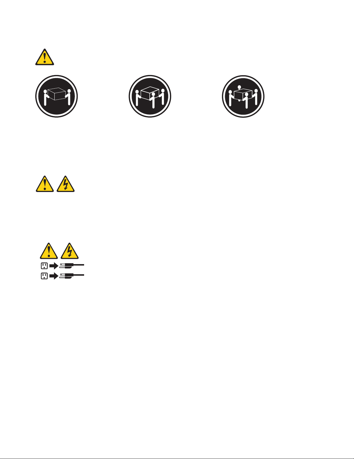
Statement 4:
≥ 18 kg (39.7 lb) ≥ 32 kg (70.5 lb) ≥ 55 kg (121.2 lb)
CAUTION:
Use safe practices when lifting.
Statement 5:
CAUTION:
The power control button on the device and the power switch on the power supply do not turn off the
electrical current supplied to the device. The device also might have more than one power cord. To
remove all electrical current from the device, ensure that all power cords are disconnected from the
power source.
2
1
6 ThinkServer ThinkServer RS210, Types 6531, 6532, 6533, and 6534: Hardware Maintenance Manual
Page 15
Statement 8:
CAUTION:
Never remove the cover on a power supply or any part that has the following label attached.
Hazardous voltage, current, and energy levels are present inside any component that has this label
attached. There are no serviceable parts inside these components. If you suspect a problem with one
of these parts, contact a service technician.
Statement 26:
CAUTION:
Do not place any object on top of rack-mounted devices.
Attention: This server is suitable for use on an IT power distribution system whose maximum
phase-to-phase voltage is 240 V under any distribution fault condition.
Important: This product is not suitable for use with visual display workplace devices according to Clause
2 of the German Ordinance for Work with Visual Display Units.
Important information about replacing RoHS compliant FRUs
RoHS, The Restriction of Hazardous Substances in Electrical and Electronic Equipment Directive
(2002/95/EC) is a European Union legal requirement affecting the global electronics industry. RoHS
requirements must be implemented on Lenovo products placed on the market and sold in the
European Union after June 2006. Products on the market before June 2006 are not required to have
RoHS compliant parts. If the parts are not compliant originally, replacement parts can also be
noncompliant, but in all cases, if the parts are compliant, the replacement parts must also be
compliant.
Note: RoHS and non-RoHS FRU part numbers with the same fit and function are identified with unique
FRU part numbers.
Lenovo plans to transition to RoHS compliance well before the implementation date and expects its
suppliers to be ready to support Lenovo’s requirements and schedule in the EU. Products sold in 2005
will contain some RoHS compliant FRUs. The following statement pertains to these products and any
product Lenovo produces containing RoHS compliant parts.
Chapter 1. About this manual 7
Page 16
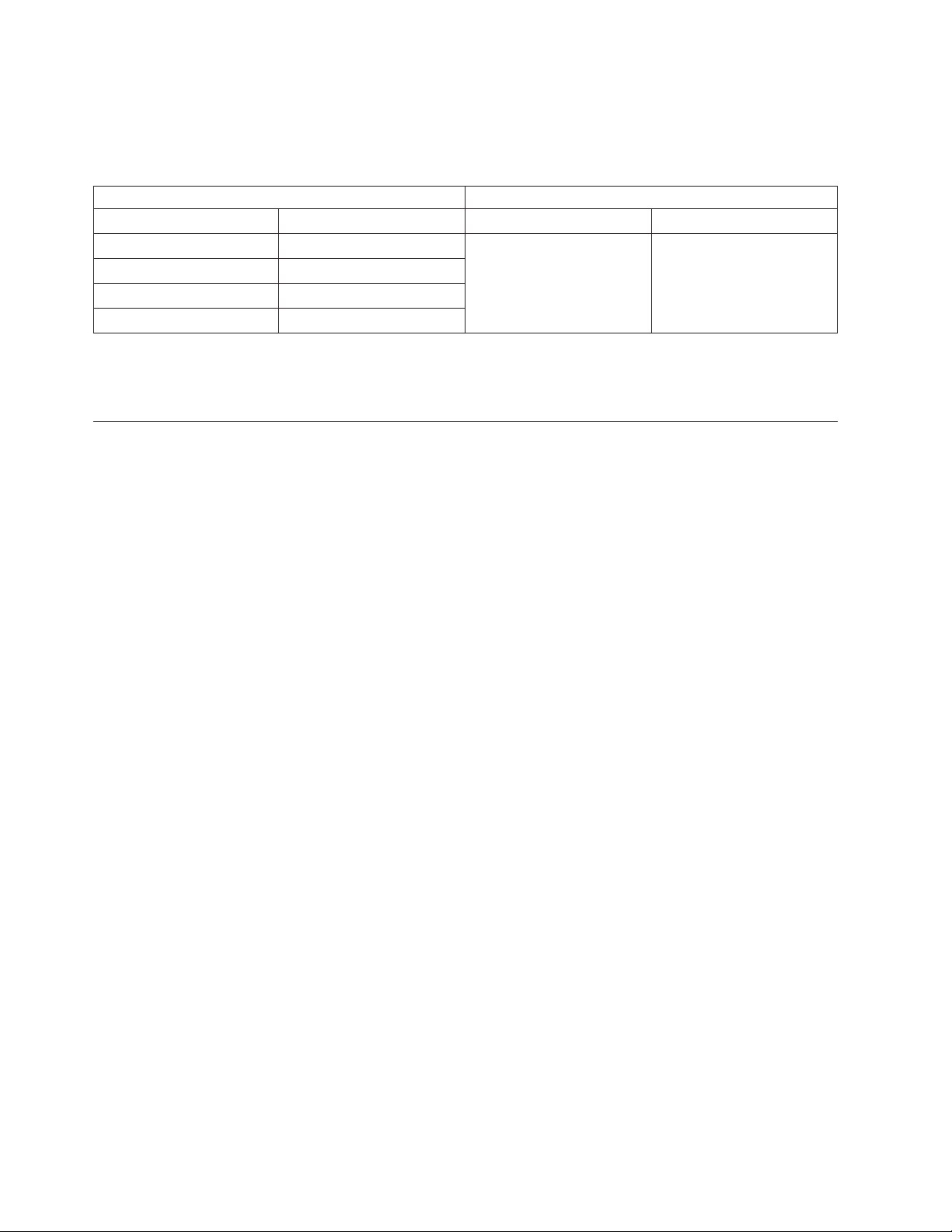
RoHS compliant ThinkServer RS210 parts have unique FRU part numbers. Before or after June, 2006,
failed RoHS compliant parts must always be replaced using RoHS compliant FRUs, so only the FRUs
identified as compliant in the system Hardware Maintenance Manual or direct substitutions for those
FRUs can be used.
Products marketed before June 2006 Products marketed after June 2006
Current or original part Replacement FRU Current or original part Replacement FRU
Non-RoHS Can be Non-RoHS Must be RoHS Must be RoHS
Non-RoHS Can be RoHS
Non-RoHS Can sub to RoHS
RoHS Must be RoHS
Note: A direct substitution is a part with a different FRU part number that is automatically shipped by
the distribution center at the time of order.
Turkish statement of compliance
The Lenovo product meets the requirements of the Republic of Turkey Directive on the Restriction of the
Use of Certain Hazardous Substances in Electrical and Electronic Equipment (EEE).
Türkiye EEE Yönetmeliğine Uygunluk Beyanı
Bu Lenovo ürünü,
ve Elektronik Eşyalarda Bazı Zararlı Maddelerin Kullanımının
Sınırlandırılmasına Dair Yönetmelik (EEE)” direktiflerine uygundur.
EEE Yönetmeliğ
T.C. Çevre ve Orman Bakanlığı'nın “Elektrik
ine Uygundur.
8 ThinkServer ThinkServer RS210, Types 6531, 6532, 6533, and 6534: Hardware Maintenance Manual
Page 17

Chapter 2. General information
This chapter provides general information that applies to all machine types supported by this publication.
Features and technologies
The server uses the following features and technologies:
v UEFI-compliant server firmware
UEFI replaces the basic input/output system (BIOS) and defines a standard interface between the
operating system, platform firmware, and external devices. The server design combines the UEFI
capabilities and features with legacy BIOS compatibility. UEFI-compliant servers are capable of starting
UEFI-compliant operating systems, BIOS-based operating systems, and BIOS-based adapters as well as
UEFI-compliant adapters.
Note: This server does not support DOS.
v Dual-core or quad-core processing
®
The server supports one Intel
v Integrated management module
The Integrated management module (IMM) combines service processor functions, video controller, and
(when an optional virtual media key is installed) remote presence function in a single chip. The IMM
provides advanced service-processor control, monitoring, and alerting function. If an environmental
condition exceeds a threshold or if a system component fails, the IMM lights LEDs to help you
diagnose the problem, records the error in the event log, and alerts you to the problem. Optionally, the
IMM also provides a virtual presence capability for remote server management capabilities. The IMM
provides remote server management through the following industry-standard interfaces:
– Intelligent Platform Management Interface (IPMI) version 2.0
– Simple Network Management Protocol (SNMP) version 3
– Common Information Model (CIM)
– Web browser
For additional information, see “Using the integrated management module” on page 215.
v Remote presence capability and blue-screen capture
The remote presence and blue-screen capture features are integrated functions of the integrated
management module (IMM) and are available with the purchase of the optional Lenovo Virtual Media
Key. A virtual media key is required to enable the remote presence and blue-screen capture features.
The remote presence feature provides the following functions:
– Remotely viewing video with graphics resolutions up to 1280 x 1024, regardless of the system state
– Remotely accessing the server, using the keyboard and mouse from a remote client
– Mapping the DVD drive, diskette drive, and USB flash drive on a remote client, and mapping ISO
and diskette image files as virtual drives that are available for use by the server
– Uploading a diskette image to the IMM memory and mapping it to the server as a virtual drive
The blue-screen capture feature captures the video display contents before the IMM restarts the server
when the IMM detects an operating-system hang condition. A system administrator can use the
blue-screen capture to assist in determining the cause of the hang condition.
See“Using the remote presence capability and blue-screen capture” on page 218 for additional
information.
v Large system-memory capability
Xeon®or Celeron®dual-core or quad-core microprocessor.
© Lenovo 2009. Portions © IBM Corp. 2007, 2009. 9
Page 18

The memory bus supports up to 24 GB of memory when registered DIMMs are installed. The server
supports up to 8 GB if unbuffered DIMMs are installed. The memory controller supports error
correcting code (ECC) for up to six industry-standard PC3-8500 or PC3-10600R-999, 1066 and 1333
MHz, DDR3 (third-generation double-data-rate), registered or unbuffered, synchronous dynamic
random access memory (SDRAM) dual inline memory modules (DIMMs).
v Integrated network support
The server comes with an integrated Intel Gigabit Ethernet controller, which supports connection to a
10 Mbps, 100 Mbps, or 1000 Mbps network. For more information, see “Configuring the Gigabit
Ethernet controllers” on page 219.
v Integrated Trust Platform Module
This integrated security chip performs cryptographic functions and stores private and public secure
keys. It provides the hardware support for the Trusted Computing Group (TCG) specification.
v Large data-storage capacity and hot-swap capability
The server supports a maximum of four 2.5-inch hot-swap Serial Attached SCSI (SAS) hard disk drives,
two 3.5-inch simple-swap Serial ATA (SATA) hard disk drives, or two 3.5-inch hot-swap SAS or SATA
hard disk drives, depending on the server model.
With the hot-swap feature, you can add, remove, or replace hard disk drives without turning off the
server.
v PCI card capabilities
The server has two PCI interface slots (one supports low-profile cards and one supports half-length,
full-height cards). Both slots can support PCI Express PCI cards.
v RAID support
The RAID controller provides hardware redundant array of independent disks (RAID) support. The
standard RAID controller provides RAID levels 0, 1, and 1E. Optional RAID PCI cards are available for
purchase that provide additional RAID levels.
v Systems-management capabilities
The server comes with an Integrated Management Module (IMM). When the IMM is used with the
systems-management software that comes with the server, you can manage the functions of the server
locally and remotely. The IMM also provides system monitoring, event recording, and network alert
capability. The systems-management connector provides additional security by physically separating
the management network traffic from the production network. You can use the Setup Utility to
configure the server to use a dedicated systems-management network or a shared network.
v TCP/IP offload engine (TOE) support
The Ethernet controllers in the server support TOE, which is a technology that offloads the TCP/IP
flow from the microprocessor and I/O subsystem to increase the speed of the TCP/IP flow. When an
operating system that supports TOE is running on the server and TOE is enabled, the server supports
TOE operation. See the operating-system documentation for information about enabling TOE.
Note: The Linux operating system does not support TOE.
v Preboot diagnostics program
The preboot diagnostics programs are stored on the integrated USB memory. They collect and analyze
system information to aid in diagnosing server problems. The diagnostic programs collect the following
information about the server:
– System configuration
– Network interfaces and settings
– Installed hardware
– Service processor status and configuration
– Vital product data, firmware, and UEFI (formerly called BIOS) configuration
– Hard disk drive health
– RAID controller configuration
10 ThinkServer ThinkServer RS210, Types 6531, 6532, 6533, and 6534: Hardware Maintenance Manual
Page 19

– Event logs for RAID controllers and service processors
The diagnostics programs create a merged log that includes events from all collected logs. The
information is collected into a file that you can send to the Lenovo technical support team to help
diagnose a problem. Additionally, you can view the information locally through a generated text report
file. You can also copy the log to a removable medium and view the HTML log from a Web browser.
For additional information about diagnostics, see Chapter 4, “Diagnostics,” on page 19.
v EasyStartup DVD
The ThinkServer EasyStartup program guides you through the configuration of RAID controllers and
the installation of the operating system and device drivers. See “Using the EasyStartup DVD” on page
209 for details.
v EasyManage DVD
The ThinkServer EasyManage program helps you manage and administer your servers through remote
problem notification as well as monitoring and alerting.
Specifications
The following information is a summary of the features and specifications of the server. Depending on
the server model, some features might not be available, or some specifications might not apply.
Table 1. Features and specifications
Microprocessor:
v Supports one Intel
3400 series) or dual-core (Celeron G1101,
Pentium G6950, or core i3 series)
processor with the IbexPeak 3420 chip
set and Multi-chip Package (MCP)
processor architecture
v Designed for LGA 1156 socket
v Scalable up to four cores
v 32 KB instruction cache, 32 KB data
cache, and up to 8 MB cache that is
shared among the cores
v Support for Intel
Technology (EM64T)
Note:
v Use the Setup utility to determine the
type and speed of the microprocessor.
Memory:
v Minimum: 1 GB
v Maximum: 32 GB
– 16 GB using unbuffered DIMMs
(UDIMMs)
– 32 GB using registered DIMMs
(RDIMMs)
v Types: PC3-8500 or PC3-10600R-999
(single-rank or double-rank), 1066, and
1333 MHz, ECC, DDR3 registered or
unbuffered SDRAM DIMMs only
v Connectors: Six dual inline memory
module (DIMM) connectors, two-way
interleaved
v Supports:
– 1 GB, 2 GB, and 4 GB (when
available) unbuffered DIMMS
– 1 GB, 2 GB, 4 GB, and 8 GB (when
available) registered DIMMs
®
quad-core (Xeon
®
Extended Memory 64
SATA optical drives:
v UltraSlim DVD-ROM combo (optional)
v Multi-burner (optional)
Hard disk drive expansion bays
(depending on the model):
One of the following configurations:
v Four 2.5-inch hot-swap SAS hard disk
drive bays
v Two 3.5-inch hot-swap SAS or hot-swap
SATA hard disk drive bays
v Two 3.5-inch simple-swap SAS hard
disk drive bays
PCI expansion slots:
Supports two PCI riser slots on the riser
card that connects to slots 1 and 2 on the
system board:
v Slot 1 supports low-profile cards (PCI
Express Gen2 x8
v Slot 2 supports 3/4-length, full-height
cards (PCI Express Gen2 x8 or PCI-X
1.0a 64-bit/133 MHz)
Power supply:
One 351-watt power supply or one
351-watt high efficiency power supply.
Fans: The server comes standard with five
speed-controlled fans.
Integrated functions:
v Integrated management module (IMM),
which provides service processor control
and monitoring functions, video
controller, and (when the optional
virtual media key is installed) remote
keyboard, video, mouse, and remote
hard disk drive capabilities
v Intel 82574L Gb Ethernet controller with
TCP/IP Offload Engine (TOE) and Wake
®
on LAN
v Seven Universal Serial Bus (USB) 2.0
ports (two front, four rear, and one
internal for the optional USB
Hypervisor flash device)
v Two Ethernet ports
v Four-port integrated SATA controller
v Integrated Trusted Platform Module
(TPM) support
v One serial port
v One VGA port
support
Chapter 2. General information
11
Page 20

Table 1. Features and specifications (continued)
RAID controllers:
v An IBM ServeRAID-BR10il SAS/SATA
Controller that provides RAID levels 0,
1, and 1E (comes standard on some
hot-swap SAS and hot-swap SATA
models).
v An optional IBM ServeRAID-MR10i
SAS/SATA Controller SAS/SATA
adapter that provides RAID levels 0, 1,
5, 6, and 10 can be ordered.
v An optional IBM ServeRAID-M1015
SAS/SATA controller that provides
RAID levels 0,1,10, and 5 can be
ordered.
Acoustical noise emissions:
v Sound power, idling: 6.5 bels maximum
v Sound power, operating: 6.5 bels
maximum
Environment:
v Air temperature:
– Server on: 10°C to 35°C (50.0°F to
95.0°F); altitude: 0 to 914.4 m (3000 ft)
– Server on: 10°C to 32°C (50.0°F to
89.6°F); altitude: 914.4 m (3000 ft) to
2133.6 m (7000.0 ft)
– Server off: 10°C to 43°C
(50°F to 109.4°F); maximum altitude:
2133.6 m (7000.0 ft)
– Shipping: -40°C to 60°C
(-104°F to 140°F)
v Humidity:
– Server on: 8% to 80%
– Server off: 8% to 80%
v Particulate contamination:
Attention: Airborne particulates and
reactive gases acting alone or in
combination with other environmental
factors such as humidity or temperature
might pose a risk to the server. For
information about the limits for
particulates and gases, see “Notices,” on
page 221.
Video controller (integrated into IMM):
v Matrox G200
v SVGA compatible video controller
v DDR2 128 MB SDRAM video memory
v Avocent Digital Video Compression
v Video memory is not expandable
Note: The maximum video resolution is
1280 x 1024
Size:
v Height: 43 mm (1.69 inches, 1U)
v Depth: 560.1 mm (22 inches)
v Width: 430 mm (17.3 inches)
v Maximum weight: 11.4 kg (25.1 lb)
when fully configured
Heat output:
Approximate heat output:
v Minimum configuration: 171 BTU per
hour (50 watts)
v Maximum configuration: 1024 BTU per
hour (300 watts)
Electrical input:
v Sine-wave input (50 / 60 Hz) required
v Input voltage low range:
– Minimum: 100 V ac
– Maximum: 127 V ac
v Input voltage high range:
– Minimum: 200 V ac
– Maximum: 240 V ac
v Input kilovolt-amperes (kVA),
approximately:
– Minimum: 0.102 kVA
– Maximum: 0.55 kVA
Notes:
1. Power consumption and heat output
vary depending on the number and
type of optional features installed and
the power-management optional
features in use.
2. The sound levels were measured in
controlled acoustical environments
according to the procedures specified
by the American National Standards
Institute (ANSI) S12.10 and ISO 7779
and are reported in accordance with
ISO 9296. Actual sound-pressure levels
in a given location might exceed the
average values stated because of room
reflections and other nearby noise
sources. The noise emission level stated
in the declared (upper limit)
sound-power level, in bels, for a
random sample of system.
3. There is no keyboard connector or
mouse connector on the server. You
can connect a USB keyboard and USB
mouse to the server by using the USB
connectors.
Software
Lenovo provides software to help get your server up and running.
EasyStartup
The ThinkServer EasyStartup program simplifies the process of configuring your RAID controllers and
installing supported Microsoft Windows and Linux operating systems and device drivers on your server.
The EasyStartup program is provided with your server on DVD. The DVD is self starting (bootable). The
User Guide for the EasyStartup program is on the DVD and can be accessed directly from the program
interface. For additional information, see “Using the EasyStartup DVD” on page 209.
12 ThinkServer ThinkServer RS210, Types 6531, 6532, 6533, and 6534: Hardware Maintenance Manual
Page 21

EasyManage
The ThinkServer EasyManage Core server provides centralized hardware and software inventory
management and secure automated system management through a centralized console. The ThinkServer
EasyManage Agent enables other clients on the network to be managed by the centralized console. The
ThinkServer EasyManage Core Server is supported on 32-bit Windows Server 2008 products. The
ThinkServer EasyManage Agent is supported on 32-bit and 64-bit Windows, Red Hat, and SUSE
operating systems.
Chapter 2. General information 13
Page 22

14 ThinkServer ThinkServer RS210, Types 6531, 6532, 6533, and 6534: Hardware Maintenance Manual
Page 23

Chapter 3. General Checkout
You can solve many problems without outside assistance by following the troubleshooting procedures in
this Hardware Maintenance Manual and on the Lenovo Web site. This document describes the diagnostic
tests that you can perform, troubleshooting procedures, and explanations of error messages and error
codes. The documentation that comes with your operating system and software also contains
troubleshooting information.
Checkout procedure
The checkout procedure is the sequence of tasks that you should follow to diagnose a problem in the
server.
About the checkout procedure
Before you perform the checkout procedure for diagnosing hardware problems, review the following
information:
v Read the safety information that begins on page 1.
v The diagnostic programs provide the primary methods of testing the major components of the server,
such as the system board, Ethernet controller, keyboard, mouse (pointing device), serial ports, and hard
disk drives. You can also use them to test some external devices. If you are not sure whether a problem
is caused by the hardware or by the software, you can use the diagnostic programs to confirm that the
hardware is working correctly.
v When you run the diagnostic programs, a single problem might cause more than one error message.
When this happens, correct the cause of the first error message. The other error messages usually will
not occur the next time you run the diagnostic programs.
Exception: If multiple error codes or system-board LEDs indicate a microprocessor error, the error
might be in the microprocessor or in the microprocessor socket. See “Microprocessor problems” on
page 58 for information about diagnosing microprocessor problems.
v Before you run the diagnostic programs, you must determine whether the failing server is part of a
shared hard disk drive cluster (two or more servers sharing external storage devices). If it is part of a
cluster, you can run all diagnostic programs except the ones that test the storage unit (that is, a hard
disk drive in the storage unit) or the storage adapter that is attached to the storage unit. The failing
server might be part of a cluster if any of the following conditions is true:
– You have identified the failing server as part of a cluster (two or more servers sharing external
storage devices).
– One or more external storage units are attached to the failing server and at least one of the attached
storage units is also attached to another server or unidentifiable device.
– One or more servers are located near the failing server.
Important: If the server is part of a shared hard disk drive cluster, run one test at a time. Do not run
any suite of tests, such as “quick” or “normal” tests, because this might enable the hard disk drive
diagnostic tests.
v If the server is halted and a POST error code is displayed, see “Event logs” on page 19. If the server is
halted and no error message is displayed, see “Troubleshooting tables” on page 50 and “Solving
undetermined problems” on page 103.
v For information about power-supply problems, see “Solving power problems” on page 102.
v For intermittent problems, check the error log; see “Event logs” on page 19 and “Diagnostic programs
and messages” on page 68.
© Lenovo 2009. Portions © IBM Corp. 2007, 2009. 15
Page 24

Performing the checkout procedure
To perform the checkout procedure, complete the following steps:
1. Is the server part of a cluster?
v No: Go to step 2.
v Yes: Shut down all failing servers that are related to the cluster. Go to step 2.
2. Complete the following steps:
a. Check the power supply LEDs (see “Power-supply LEDs” on page 67).
b. Turn off the server and all external devices.
c. Check all internal and external devices for compatibility at http://www.lenovo.com/support.
d. Check all cables and power cords.
e. Set all display controls to the middle positions.
f. Turn on all external devices.
g. Turn on the server. If the server does not start, see “Troubleshooting tables” on page 50.
h. Check the system-error LED on the operator information panel. If it is flashing, check the LEDs on
the system board (see “System-board LEDs” on page 112).
i. Check for the following results:
v Successful completion of POST (see “POST” on page 21 for more information)
v Successful completion of startup
Diagnosing a problem
Before you contact Lenovo or an approved warranty service provider, follow these procedures in the
order in which they are presented to diagnose a problem with your server:
1. Determine what has changed.
Determine whether any of the following items were added, removed, replaced, or updated before the
problem occurred:
v Device drivers
v Server firmware
v Hardware components
v Software
If possible, return the server to the condition it was in before the problem occurred.
2. Collect data.
Thorough data collection is necessary for diagnosing hardware and software problems.
a. Document error codes and system-board LEDs.
v System error codes: See “POST error codes” on page 21 for information about a specific error
code.
v See “System-board LEDs” on page 112 for the location of the system-board LEDs.
v Software or operating-system error codes: See the documentation for the software or operating
system for information about a specific error code. See the manufacturer’s Web site for
documentation.
b. Collect system data.
Run the Dynamic System Analysis (DSA) diagnostics program to collect information about the
hardware, firmware, software, and operating system. Have this information available when you
contact Lenovo or an approved warranty service provider. See “Diagnostic programs and
messages” on page 68 for the instructions to run the DSA program.
If you need to download the latest version of DSA , go to http://www.lenovo.com/support.
3. Follow the problem-resolution procedures.
16 ThinkServer ThinkServer RS210, Types 6531, 6532, 6533, and 6534: Hardware Maintenance Manual
Page 25

The four problem-resolution procedures are presented in the order in which they are most likely to
solve your problem. Follow these procedures in the order in which they are presented:
a. Check for and apply code updates.
Most problems that appear to be caused by faulty hardware are actually caused by the server
firmware (formerly BIOS firmware), device firmware, or device drivers that are not at the latest
levels.
1) Determine the existing code levels.
In DSA, click Firmware/VPD to view system firmware levels, or click Software to view
operating-system levels.
2) Download and install updates of code that is not at the latest level.
Important: Some cluster solutions require specific code levels or coordinated code updates. If
the device is part of a cluster solution, verify that the latest level of code is supported for the
cluster solution before you update the code.
To display a list of available updates for your server, go to http://www.lenovo.com/support.
When you click an update, an information page is displayed, including a list of the problems
that the update fixes. Review this list for your specific problem; however, even if your problem
is not listed, installing the update might solve the problem.
b. Check for and correct an incorrect configuration.
If the server is incorrectly configured, a system function can fail to work when you enable it; if
you make an incorrect change to the server configuration, a system function that has been enabled
can stop working.
1) Make sure that all installed hardware and software are supported.
See http://www.lenovo.com/support to verify that the server supports the installed operating
system, optional devices, and software levels. If any hardware or software component is not
supported, uninstall it to determine whether it is causing the problem. You must remove
nonsupported hardware before you contact Lenovo or an approved warranty service provider
for support.
2) Make sure that the server, operating system, and software are installed and configured
correctly.
Many configuration problems are caused by loose power or signal cables or incorrectly seated
adapters. You might be able to solve the problem by turning off the server, reconnecting cables,
reseating adapters, and turning the server back on. See “Checkout procedure” on page 15 for
the instructions to perform the checkout procedures.
If the problem is associated with a specific function (for example, if a RAID hard disk drive is
marked offline in the RAID array), see the documentation for the associated controller and
management or controlling software to verify that the controller is correctly configured.
Problem determination information is available for many devices such as RAID and network
adapters.
For problems with operating systems or Lenovo software or devices, complete the following
steps.
Note: Changes are made periodically to the Lenovo Web site. The actual procedure might vary
slightly from what is described in this document.
a) Go to: http://www.lenovo.com/support.
b) From the Select your product list, select Servers and Storage.
c) In the Browse by product window Family: list, select ThinkServer RS210.
d) Click Downloads and drivers .
e) Click User’s guides and manuals to look for related documentation.
c. Check for service bulletins.
Chapter 3. General Checkout 17
Page 26

Lenovo service bulletins document known problems and suggested solutions. To search for service
bulletins, complete the following steps.
1) Go to: http://www.lenovo.com/support.
2) From the Select your product list, select Servers and Storage.
3) In the Browse by product window Family: list, select ThinkServer RS210.
4) Click Downloads and drivers to look for service information.
Note: Changes are made periodically to the Lenovo Web site. The actual procedure might vary
slightly from what is described in this document.
d. Check for and replace defective hardware.
If a hardware component is not operating within specifications, it can cause unpredictable results.
Most hardware failures are reported as error codes in a system or operating-system log. See
“Troubleshooting tables” on page 50 and Chapter 6, “Replacing FRUs,” on page 115 for more
information. Hardware errors are also indicated by LEDs on the system board (see “System-board
LEDs” on page 112 for more information).
Troubleshooting procedures are also provided on the Lenovo Web site. A single problem might
cause multiple symptoms. Follow the diagnostic procedure for the most obvious symptom. If that
procedure does not diagnose the problem, use the procedure for another symptom, if possible. To
locate troubleshooting procedures for your server, complete the following steps.
Note: Changes are made periodically to the Lenovo Web site. The actual procedure might vary
slightly from what is described in this document.
1) Go to: http://www.lenovo.com/support.
2) From the Select your product list, select Servers and Storage.
3) In the Browse by product window Family: list, select ThinkServer RS210.
4) Under Support & downloads, click Troubleshoot.
5) Under Diagnostic, select the troubleshooting procedure for the symptom that you are
observing.
For more troubleshooting information, see Chapter 4, “Diagnostics,” on page 19.
If the problem remains, contact Lenovo or an approved warranty service provider for assistance
with additional problem determination and possible hardware replacement. Be prepared to
provide information about any error codes and collected data.
Undocumented problems
If you have completed the diagnostic procedure and the problem remains, the problem might not have
been previously identified by Lenovo. After you have verified that all code is at the latest level, all
hardware and software configurations are valid, and no LEDs or log entries indicate a hardware
component failure, contact Lenovo or an approved warranty service provider for assistance. Be prepared
to provide information about any error codes and collected data and the problem determination
procedures that you have used.
18 ThinkServer ThinkServer RS210, Types 6531, 6532, 6533, and 6534: Hardware Maintenance Manual
Page 27

Chapter 4. Diagnostics
This chapter describes the diagnostic tools that are available to help you solve problems that might occur
in the server.
Diagnostic tools
The following tools are available to help you diagnose and solve hardware-related problems:
v POST error messages and error logs
The power-on self-test (POST) generates messages to indicate successful test completion or the
detection of a problem. See “POST” on page 21, “Event logs,” and “POST error codes” on page 21 for
more information.
v Troubleshooting tables
These tables list problem symptoms and actions to correct the problems. See “Troubleshooting tables”
on page 50 for more information.
v Dynamic System Analysis (DSA) Preboot diagnostic programs
The DSA Preboot diagnostic programs provide problem isolation, configuration analysis, and error log
collection. The diagnostic programs are the primary method of testing the major components of the
server and are stored in integrated USB memory. The diagnostic programs collect the following
information about the server:
– System configuration
– Network interfaces and settings
– Installed hardware
– Service processor status and configuration
– Vital product data, firmware, and UEFI configuration
– Hard disk drive health
– RAID controller configuration
– Controller and service processor event logs, including the following information:
- System error logs
- Temperature, voltage, and fan speed information
- Self-monitoring Analysis, and Reporting Technology (SMART) data
- Machine check registers
- USB information
- Monitor configuration information
- PCI slot information
The diagnostic programs create a merged log that includes events from all collected logs. The
information is collected into a file that you can send to Lenovo service and support. Additionally, you
can view the server information locally through a generated text report file. You can also copy the log
to removable media and view the log from a Web browser. See “Running the diagnostic programs” on
page 69 for more information.
v Server LEDs
Use the LEDs on the server to diagnose system errors quickly. See “System-board LEDs” on page 112
for more information.
Event logs
Error codes and messages are displayed in the following types of event logs:
v POST event log: This log contains the three most recent error codes and messages that were generated
during POST. You can view the POST event log through the Setup utility.
© Lenovo 2009. Portions © IBM Corp. 2007, 2009. 19
Page 28

v System-event log: This log contains messages that were generated during POST and all system status
messages from the service processor. You can view the contents of the system-event log from the Setup
utility for more information.
The system-event log is limited in size. When it is full, new entries will not overwrite existing entries;
therefore, you must periodically clear the system-event log through the Setup utility. When you are
troubleshooting, you might have to clear the system-event log to make the most recent events available
for analysis.
Each system-event log entry is displayed on its own page. Message are listed on the left side of the
screen, and details about the selected message is displayed on the right side of the screen. To move
from one entry to the next, use the Up Arrow (↑) and Down Arrow (↓) keys.
The system-event log indicates an assertion event when an event has occurred. It indicates a
de-assertion event when the event is no longer occurring.
v Integrated management module (IMM) event log: This log contains a filtered subset of all IMM,
POST, and system management interrupt (SMI) events. You can view the IMM event log through the
IMM Web interface and through the Dynamic System Analysis (DSA) program (as the ASM event log).
v DSA log: This log is generated by the Dynamic System Analysis (DSA) program, and it is a
chronologically ordered merge of the system-event log (as the IPMI event log), the IMM chassis-event
log (as the ASM event log), and the operating-system event logs. You can view the DSA log through
the DSA program.
Viewing event logs through the Setup utility
To view the POST event log or system-event log, complete the following steps:
1. Turn on the server.
2. When the prompt <F1> Setup is displayed, press F1. If you have set both a power-on password and
an administrator password, you must type the administrator password to view the event logs.
3. Select System Event Logs and use one of the following procedures:
v To view the POST event log, select POST Event Viewer.
v To view the IMM system-event log, select System Event Log.
Viewing event logs without restarting the server
When the server is not hung and the IMM is connected to a network, methods are available for you to
view one or more event logs without having to restart the server.
You can use the DSA Preboot to view the system event log (as the IPMI event log), the IMM event log (as
the ASM event log), or the merged DSA log. You must restart the server to use DSA Preboot to view
those logs.
You can view the IMM system event log through the Event Log link in the integrated management
module (IMM) Web interface.
Table 2. Methods for viewing event logs
Condition Action
The server is not hung and is connected to a network.
The server is not hung and is not connected to a
network.
v Use IPMItool to view the system-event log.
Use IPMItool locally to view the system-event log.
20 ThinkServer ThinkServer RS210, Types 6531, 6532, 6533, and 6534: Hardware Maintenance Manual
Page 29

Table 2. Methods for viewing event logs (continued)
Condition Action
The server is hung.
v If DSA Preboot is installed, restart the server and press
F2 to start DSA Preboot and view the event logs.
v If DSA Preboot is not installed, insert the DSA Preboot
CD and restart the server to start DSA Preboot and
view the event logs.
v Alternatively, you can restart the server and press F1
to start the Setup utility and view the POST event log
or system-event log. For more information, see
“Viewing event logs without restarting the server” on
page 20.
Clearing the event logs
To clear the event logs, complete the following steps.
Note: The POST event log is automatically cleared each time the server is restarted.
1. Turn on the server.
2. When the prompt <F1> Setup is displayed, press F1. If you have set both a power-on password and
an administrator password, you must type the administrator password to view the error logs.
3. Use one of the following procedures:
v To clear the IMM system-event log, select System Event Logs --> System Event Log. Select Clear
System Event Log; then, press Enter twice.
POST
When you turn on the server, it performs a series of tests to check the operation of the server components
and some optional devices in the server. This series of tests is called the power-on self-test, or POST.
Note: This server does not use beep codes for server status.
If a power-on password is set, you must type the password and press Enter, when you are prompted, for
POST to run.
If POST detects a problem, an error message is displayed. See “POST error codes” for more information.
POST error codes
The following table describes the POST error codes and suggested actions to correct the detected
problems. These errors can appear as severe, warning, or informational.
Chapter 4. Diagnostics 21
Page 30

v Follow the suggested actions in the order in which they are listed in the Action column until the problem is
solved.
v See Chapter 7, “Parts listing, RS210 Types 6531, 6532, 6533, and 6534,” on page 177 to determine which
components are customer replaceable units (CRU) and which components are field replaceable units (FRU).
v If an action step is preceded by “(Trained service technician only),” that step must be performed only by a
trained service technician.
v Go to the Lenovo support Web site at http://www.lenovo.com/support to check for technical information, hints,
tips, and new device drivers or to submit a request for information.
Error code Description Action
0010002 Microprocessor not supported.
0011000 Invalid microprocessor type.
0011004 Microprocessor failed BIST.
001100A Microcode updated failed.
0050001 DIMM disabled.
1. (Trained service technician only) Reseat the
microprocessor and restart the server.
2. (Trained service technician only) Remove the
microprocessor and install a new microprocessor.
Restart the server. If the error is corrected, the old
microprocessor is bad and must be replaced.
3. Replace the following components one at a time,
in the order shown, restarting the server each
time.
a. (Trained service technician only)
Microprocessor
b. (Trained service technician only) System board
1. Update the server firmware to the latest level (see
“Updating the firmware” on page 212).
2. (Trained service technician only) Remove and
replace the affected microprocessor (error LED is
lit) with a supported type (see “Installing the
microprocessor” on page 141).
1. Update the server firmware to the latest level (see
“Updating the firmware” on page 212).
2. (Trained service technician only) Reseat the
microprocessor.
3. Replace the following components one at a time,
in the order shown, restarting the server each
time:
a. (Trained service technician only)
Microprocessor
b. (Trained service technician only) System board
1. Update the server firmware to the latest level (see
“Updating the firmware” on page 212).
2. (Trained service technician only) Replace the
microprocessor.
1. If the server fails the POST memory test, reseat
the DIMMs.
2. Remove and replace any DIMM for which the
associated error LED is lit (see “Removing a
memory module” on page 124 and “Installing a
memory module” on page 125).
3. Run the Setup utility to enable all the DIMMs.
4. Run the DSA Preboot memory test (see “Running
the diagnostic programs” on page 69).
22 ThinkServer ThinkServer RS210, Types 6531, 6532, 6533, and 6534: Hardware Maintenance Manual
Page 31

v Follow the suggested actions in the order in which they are listed in the Action column until the problem is
solved.
v See Chapter 7, “Parts listing, RS210 Types 6531, 6532, 6533, and 6534,” on page 177 to determine which
components are customer replaceable units (CRU) and which components are field replaceable units (FRU).
v If an action step is preceded by “(Trained service technician only),” that step must be performed only by a
trained service technician.
v Go to the Lenovo support Web site at http://www.lenovo.com/support to check for technical information, hints,
tips, and new device drivers or to submit a request for information.
Error code Description Action
0051003 Uncorrectable DIMM error
1. If the server failed the POST memory test, reseat
the DIMMs.
2. Remove and replace any DIMM for which the
associated error LED is lit (see “Removing a
memory module” on page 124 and “Installing a
memory module” on page 125).
3. Run the Setup utility to enable all the DIMMs.
4. Run the DSA Preboot memory test (see“Running
the diagnostic programs” on page 69).
0051006 DIMM mismatch detected Make sure that the DIMMs match and are installed in
the correct sequence (see “Installing a memory
module” on page 125).
0051009 No memory detected.
1. Make sure that the server contains DIMMs.
2. Reseat the DIMMs.
3. Install DIMMs in the correct sequence (see
“Installing a memory module” on page 125).
005100A No usable memory detected.
1. Make sure that the server contains DIMMs.
2. Reseat the DIMMs.
3. Install DIMMs in the correct sequence (see
“Installing a memory module” on page 125).
4. Clear CMOS memory to re-enable all the memory
connectors (see “System-board switches and
jumpers” on page 111).
0058001 PFA threshold exceeded
1. Update the server firmware to the latest level (see
“Updating the firmware” on page 212).
2. Reseat the DIMMs and run the memory test (see
“Running the diagnostic programs” on page 69).
3. Replace the failing DIMM, which is indicated by
a lit LED on the system board.
Chapter 4. Diagnostics 23
Page 32

v Follow the suggested actions in the order in which they are listed in the Action column until the problem is
solved.
v See Chapter 7, “Parts listing, RS210 Types 6531, 6532, 6533, and 6534,” on page 177 to determine which
components are customer replaceable units (CRU) and which components are field replaceable units (FRU).
v If an action step is preceded by “(Trained service technician only),” that step must be performed only by a
trained service technician.
v Go to the Lenovo support Web site at http://www.lenovo.com/support to check for technical information, hints,
tips, and new device drivers or to submit a request for information.
Error code Description Action
0058007 DIMM population is unsupported.
0058008 DIMM failed memory test.
00580A4 Memory population changed. Information only. Memory has been added, moved,
0068002 CMOS battery cleared.
2011001 PCI-X PERR
1. Reseat the DIMMs, and then restart the server.
2. Remove the lowest-numbered DIMM pair of
those that are identified and replace it with an
identical pair of known good DIMMs, then restart
the server.
3. Return the removed DIMMs, one pair at a time,
to their original connectors, restarting the server
after each pair, until a pair fails. Replace the
DIMMs in the failed pair with identical known
good DIMMs, restarting the server after each
DIMM is installed. Replace the failed DIMM.
Repeat this step until you have tested all removed
DIMMs.
4. (Trained service technician only) Replace the
system board.
1. Reseat the DIMMs, and then restart the server.
2. Replace the following components one at a time,
in the order shown, then restart the server after
each:
a. DIMM
b. (Trained service technician only) System board
or changed.
1. Reseat the battery.
2. Clear the CMOS memory (see Table 6 on page
111).
3. Replace the following components one at a time,
in the following order, restarting the server after
each one:
a. Battery
b. (Trained service technician only) System board
1. Check the riser-card LEDs.
2. Reseat all affected adapters and riser cards.
3. Update the PCI adapter firmware.
4. Remove the adapter from the riser card.
5. Replace the following components one at a time,
in the order shown, restarting the server each
time:
a. Riser card
b. (Trained service technician only) System board
24 ThinkServer ThinkServer RS210, Types 6531, 6532, 6533, and 6534: Hardware Maintenance Manual
Page 33

v Follow the suggested actions in the order in which they are listed in the Action column until the problem is
solved.
v See Chapter 7, “Parts listing, RS210 Types 6531, 6532, 6533, and 6534,” on page 177 to determine which
components are customer replaceable units (CRU) and which components are field replaceable units (FRU).
v If an action step is preceded by “(Trained service technician only),” that step must be performed only by a
trained service technician.
v Go to the Lenovo support Web site at http://www.lenovo.com/support to check for technical information, hints,
tips, and new device drivers or to submit a request for information.
Error code Description Action
2018001 PCI Express uncorrected or uncorrected error
1. Check the riser-card LEDs.
2. Reseat all affected adapters and riser cards.
3. Update the PCI adapter firmware.
4. Remove the adapter from the riser card.
5. Replace the following components one at a time,
in the order shown, restarting the server each
time:
a. Riser card
b. (Trained service technician only) System board
2018002 Option ROM resource allocation failure Informational message that some devices might not
be initialized.
1. If possible, rearrange the order of the adapters in
the PCI slots to change the load order of the
optional-device ROM code.
2. Run the Setup utility, select Startup Options, and
change the boot priority to change the load order
of the optional-device ROM code.
3. Run the Setup utility and disable some other
resources, if their functions are not being used, to
make more space available.
a. Select Startup Options → Planar Ethernet
(PXE/DHCP) to disable the integrated
Ethernet controller ROM.
b. Select Advanced Functions → PCI Bus Control
→ PCI ROM Control Execution to disable the
ROM of the adapter in the PCI slots.
c. Select Devices and I/O Ports to disable any of
the integrated devices.
4. Replace the following components one at a time,
in the order shown, restarting the server each
time:
a. Each adapter
b. (Trained service technician only) System board
3xx0007 (xx
can be 00 -
19)
Firmware fault detected, system halted
1. Recover the server firmware to the latest level.
2. Undo any recent configuration changes, or clear
CMOS memory to restore the settings to the
default values (see Table 6 on page 111).
3. Remove any recently installed hardware.
Chapter 4. Diagnostics 25
Page 34

v Follow the suggested actions in the order in which they are listed in the Action column until the problem is
solved.
v See Chapter 7, “Parts listing, RS210 Types 6531, 6532, 6533, and 6534,” on page 177 to determine which
components are customer replaceable units (CRU) and which components are field replaceable units (FRU).
v If an action step is preceded by “(Trained service technician only),” that step must be performed only by a
trained service technician.
v Go to the Lenovo support Web site at http://www.lenovo.com/support to check for technical information, hints,
tips, and new device drivers or to submit a request for information.
Error code Description Action
3038003 Firmware corrupted
3048005 Booted secondary (backup) UEFI image Information message that the backup UEFI settings
3048006 Booted secondary (backup) UEFI image
because of ABR
305000A RTC date/time is incorrect
3058001 System configuration invalid
1. Run the Setup utility, select Load Default
Settings, and save the settings to recover the
server firmware.
2. (Trained service technician only) Replace the
system board.
are used.
1. Run the Setup utility, select Load Default
Settings, and save the settings to recover the
primary UEFI settings.
2. Turn off the server and remove it from the power
source.
3. Reconnect the server to the power source, then
turn on the server.
1. Adjust the date and time settings in the Setup
utility, and then restart the server.
2. Reseat the battery.
3. Replace the following components one at a time,
in the order shown, restarting the server each
time:
a. Battery
b. (Trained service technician only) System board
1. Run the Setup utility, and select Save Settings.
2. Run the Setup utility, select Load Default
Settings, and save the settings.
3. Replace the following components one at a time,
in the order shown, restarting the server each
time:
a. Battery
b. Failing device (if the device is a FRU, it must
be replaced by a trained service technician
only)
c. (Trained service technician only) System board
26 ThinkServer ThinkServer RS210, Types 6531, 6532, 6533, and 6534: Hardware Maintenance Manual
Page 35

v Follow the suggested actions in the order in which they are listed in the Action column until the problem is
solved.
v See Chapter 7, “Parts listing, RS210 Types 6531, 6532, 6533, and 6534,” on page 177 to determine which
components are customer replaceable units (CRU) and which components are field replaceable units (FRU).
v If an action step is preceded by “(Trained service technician only),” that step must be performed only by a
trained service technician.
v Go to the Lenovo support Web site at http://www.lenovo.com/support to check for technical information, hints,
tips, and new device drivers or to submit a request for information.
Error code Description Action
3058004 Three boot failure
1. Undo any recent system changes, such as new
settings or newly installed devices.
2. Make sure that the server is attached to a reliable
power source.
3. Make sure that the operating system is not
corrupted.
4. Run the Setup utility, save the configuration, and
then restart the server.
5. See “Problem determination tips” on page 104.
3108007 System configuration restored to default
settings
3138002 Boot configuration error
Information only. This message is usually associated
with the CMOS battery clear event.
1. Remove any recent configuration changes made
to the Setup utility.
2. Run the Setup utility, select Load Default
Settings, and save the settings.
3808000 IMM communication failure
1. Remove power from the server for 30 seconds,
and then reconnect the server to power and
restart it.
2. Update the IMM firmware to the latest level (see
“Updating the firmware” on page 212).
3. Make sure that the virtual media key is seated
and not damaged.
4. (Trained service technician only) Replace the
system board.
3808002 Error updating system configuration to IMM
1. Remove power from the server, and then
reconnect the server to power and restart it.
2. Run the Setup utility and select Save Settings.
3. Update the IMM firmware to the latest level (see
“Updating the firmware” on page 212).
3808003 Error retrieving system configuration from
IMM
1. Remove power from the server, and then
reconnect the server to power and restart it.
2. Run the Setup utility and select Save Settings.
3. Update the IMM firmware to the latest level (see
“Updating the firmware” on page 212).
Chapter 4. Diagnostics 27
Page 36

v Follow the suggested actions in the order in which they are listed in the Action column until the problem is
solved.
v See Chapter 7, “Parts listing, RS210 Types 6531, 6532, 6533, and 6534,” on page 177 to determine which
components are customer replaceable units (CRU) and which components are field replaceable units (FRU).
v If an action step is preceded by “(Trained service technician only),” that step must be performed only by a
trained service technician.
v Go to the Lenovo support Web site at http://www.lenovo.com/support to check for technical information, hints,
tips, and new device drivers or to submit a request for information.
Error code Description Action
3808004 IMM system event log full
3818001 Core Root of Trust Measurement (CRTM)
update failed
3818002 Core Root of Trust Measurement (CRTM)
update aborted
3818003 Core Root of Trust Measurement (CRTM)
flash lock failed
3818004 Core Root of Trust Measurement (CRTM)
system error
3818005 Current Bank Core Root of Trust
Measurement (CRTM) capsule signature
invalid
3818006 Opposite bank CRTM capsule signature
invalid
3818007 CRTM update capsule signature invalid
v When using out-of-band, use the IMM Web
interface or IPMItool to clear the logs from the
operating system.
v When using the local console:
1. Run the Setup utility.
2. Select System Event Log.
3. Select Clear System Event Log.
4. Restart the server.
1. Run the Setup utility, select Load Default
Settings, and save the settings.
2. (Trained service technician only) Replace the
system board.
1. Run the Setup utility, select Load Default
Settings, and save the settings.
2. (Trained service technician only) Replace the
system board.
1. Run the Setup utility, select Load Default
Settings, and save the settings.
2. (Trained service technician only) Replace the
system board.
1. Run the Setup utility, select Load Default
Settings, and save the settings.
2. (Trained service technician only) Replace the
system board.
1. Run the Setup utility, select Load Default
Settings, and save the settings.
2. (Trained service technician only) Replace the
system board.
1. Switch the server firmware bank to the backup
bank (see “Starting the backup server firmware”
on page 213).
2. Run the Setup utility, select Load Default
Settings, and save the settings.
3. Switch the bank back to the primary bank.
4. (Trained service technician only) Replace the
system board.
1. Run the Setup utility, select Load Default
Settings, and save the settings.
2. (Trained service technician only) Replace the
system board.
28 ThinkServer ThinkServer RS210, Types 6531, 6532, 6533, and 6534: Hardware Maintenance Manual
Page 37

v Follow the suggested actions in the order in which they are listed in the Action column until the problem is
solved.
v See Chapter 7, “Parts listing, RS210 Types 6531, 6532, 6533, and 6534,” on page 177 to determine which
components are customer replaceable units (CRU) and which components are field replaceable units (FRU).
v If an action step is preceded by “(Trained service technician only),” that step must be performed only by a
trained service technician.
v Go to the Lenovo support Web site at http://www.lenovo.com/support to check for technical information, hints,
tips, and new device drivers or to submit a request for information.
Error code Description Action
3828004 AEM power capping disabled
1. Check the settings and the event logs.
2. Make sure that the Active Energy Manager
feature is enabled in the Setup utility. Click
System Settings → Power → Active Energy
Manager → Capping Enabled .
3. Update the server firmware to the latest level (see
“Updating the firmware” on page 212).
4. Update the IMM firmware to the latest level (see
“Updating the firmware” on page 212).
System-event log
The system-event log contains messages of three types:
Information
Information messages do not require action; they record significant system-level events, such as
when the server is started.
Warning
Warning messages do not require immediate action; they indicate possible problems, such as
when the recommended maximum ambient temperature is exceeded.
Error Error messages might require action; they indicate system errors, such as when a fan is not
detected.
Each message contains date and time information, and it indicates the source of the message (POST or
the IMM).
Chapter 4. Diagnostics 29
Page 38

Integrated management module error messages
The following table describes the IMM error messages and suggested actions to correct the detected
problems.
v Follow the suggested actions in the order in which they are listed in the Action column until the problem is
solved.
v See Chapter 7, “Parts listing, RS210 Types 6531, 6532, 6533, and 6534,” on page 177 to determine which
components are customer replaceable units (CRU) and which components are field replaceable units (FRU).
v If an action step is preceded by “(Trained service technician only),” that step must be performed only by a
trained service technician.
Message Severity Description Action
Numeric sensor Ambient Temp
going high (upper critical) has
asserted.
Numeric sensor Ambient Temp
going high (upper non-recoverable)
has asserted.
Numeric sensor Planar 3.3V going
low (lower critical) has asserted.
Numeric sensor Planar 3.3V going
high (upper critical) has asserted.
Numeric sensor Planar 5V going low
(lower critical) has asserted.
Numeric sensor Planar 5V going
high (upper critical) has asserted.
Numeric sensor Planar VBAT going
low (lower critical) has asserted.
Numeric sensor Fan n Tach going
low (lower critical) has asserted.
(n = fan number)
Error An upper critical sensor
going high has asserted.
Error An upper nonrecoverable
sensor going high has
asserted.
Error A lower critical sensor going
low has asserted.
Error An upper critical sensor
going high has asserted.
Error A lower critical sensor going
low has asserted.
Error An upper critical sensor
going high has asserted.
Error A lower critical sensor going
low has asserted.
Error A lower critical sensor going
low has asserted.
Reduce the ambient temperature.
Reduce the ambient temperature.
(Trained service technician only)
Replace the system board.
(Trained service technician only)
Replace the system board.
(Trained service technician only)
Replace the system board.
(Trained service technician only)
Replace the system board.
Replace the 3 V battery.
1. Reseat the failing fan n, which
is indicated by a lit LED on
the system board (see
“System-board LEDs” on
page 112).
2. Replace the failing fan.
(n = fan number)
30 ThinkServer ThinkServer RS210, Types 6531, 6532, 6533, and 6534: Hardware Maintenance Manual
Page 39

v Follow the suggested actions in the order in which they are listed in the Action column until the problem is
solved.
v See Chapter 7, “Parts listing, RS210 Types 6531, 6532, 6533, and 6534,” on page 177 to determine which
components are customer replaceable units (CRU) and which components are field replaceable units (FRU).
v If an action step is preceded by “(Trained service technician only),” that step must be performed only by a
trained service technician.
The Processor CPU nStatus has
Failed with IERR.
(n = microprocessor number)
Error A processor failed - IERR
condition has occurred.
1. Make sure that the latest
levels of firmware and device
drivers are installed for all
adapters and standard
devices, such as Ethernet,
SCSI, and SAS.
Important: Some cluster
solutions require specific code
levels or coordinated code
updates. If the device is part
of a cluster solution, verify
that the latest level of code is
supported for the cluster
solution before you update
the code.
2. Run the DSA program for the
hard disk drives and other
I/O devices.
3. (Trained service technician
only) Replace microprocessor
n.
(n = microprocessor number)
An Over-Temperature Condition has
been detected on the Processor CPU
nStatus.
(n = microprocessor number)
Error An overtemperature
condition has occurred for
microprocessor n.
(n = microprocessor number)
1. Make sure that the fans are
operating, that there are no
obstructions to the airflow,
that the air baffle is in place
and correctly installed, and
that the server cover is
installed and completely
closed.
2. Make sure that the heat sink
for microprocessor n is
installed correctly.
3. (Trained service technician
only) Replace microprocessor
n.
(n = microprocessor number)
Chapter 4. Diagnostics 31
Page 40

v Follow the suggested actions in the order in which they are listed in the Action column until the problem is
solved.
v See Chapter 7, “Parts listing, RS210 Types 6531, 6532, 6533, and 6534,” on page 177 to determine which
components are customer replaceable units (CRU) and which components are field replaceable units (FRU).
v If an action step is preceded by “(Trained service technician only),” that step must be performed only by a
trained service technician.
The Processor CPU nStatus has
Failed with FRB1/BIST condition.
(n = microprocessor number)
The Processor CPU nStatus has a
Configuration Mismatch.
(n = microprocessor number)
An SM BIOS Uncorrectable CPU
complex error for Processor CPU
nStatus has asserted.
(n = microprocessor number)
Error A processor failed -
FRB1/BIST condition has
occurred.
Error A processor configuration
mismatch has occurred.
Error An SMBIOS uncorrectable
CPU complex error has
asserted.
1. Check for a server firmware
update.
Important:: Some cluster
solutions require specific code
levels or coordinated code
updates. If the device is part
of a cluster solution, verify
that the latest level of code is
supported for the cluster
solution before you update
the code.
2. (Trained service technician
only) Reseat microprocessor
n.
3. (Trained service technician
only) Replace microprocessor
n.
(n = microprocessor number)
1. (Trained service technician
only) Replace the
microprocessor.
1. Check for a server firmware
update.
Important: Some cluster
solutions require specific code
levels or coordinated code
updates. If the device is part
of a cluster solution, verify
that the latest level of code is
supported for the cluster
solution before you update
the code.
2. (Trained service technician
only) Reseat microprocessor
n.
3. (Trained service technician
only) Replace microprocessor
n.
(n = microprocessor number)
32 ThinkServer ThinkServer RS210, Types 6531, 6532, 6533, and 6534: Hardware Maintenance Manual
Page 41

v Follow the suggested actions in the order in which they are listed in the Action column until the problem is
solved.
v See Chapter 7, “Parts listing, RS210 Types 6531, 6532, 6533, and 6534,” on page 177 to determine which
components are customer replaceable units (CRU) and which components are field replaceable units (FRU).
v If an action step is preceded by “(Trained service technician only),” that step must be performed only by a
trained service technician.
Sensor CPU nOverTemp has
transitioned to critical from a less
severe state.
(n = microprocessor number)
Error A sensor has changed to
Critical state from a less
severe state.
1. Make sure that the fans are
operating, that there are no
obstructions to the airflow,
that the air baffle is in place
and correctly installed, and
that the server cover is
installed and completely
closed.
2. Make sure that the heat sink
for microprocessor n is
installed correctly.
3. (Trained service technician
only) Replace microprocessor
n.
(n = microprocessor number)
Sensor CPU nOverTemp has
transitioned to non-recoverable from
a less severe state.
(n = microprocessor number)
Error A sensor has changed to
Nonrecoverable state from a
less severe state.
1. Make sure that the fans are
operating, that there are no
obstructions to the airflow,
that the air baffle is in place
and correctly installed, and
that the server cover is
installed and completely
closed.
2. Make sure that the heat sink
for microprocessor n is
installed correctly.
3. (Trained service technician
only) Replace microprocessor
n.
(n = microprocessor number)
Sensor CPU nOverTemp has
transitioned to critical from a
non-recoverable state.
(n = microprocessor number)
Error A sensor has changed to
Critical state from
Nonrecoverable state.
1. Make sure that the fans are
operating, that there are no
obstructions to the airflow,
that the air baffle is in place
and correctly installed, and
that the server cover is
installed and completely
closed.
2. Make sure that the heat sink
for microprocessor n is
installed correctly.
3. (Trained service technician
only) Replace microprocessor
n.
(n = microprocessor number)
Chapter 4. Diagnostics 33
Page 42

v Follow the suggested actions in the order in which they are listed in the Action column until the problem is
solved.
v See Chapter 7, “Parts listing, RS210 Types 6531, 6532, 6533, and 6534,” on page 177 to determine which
components are customer replaceable units (CRU) and which components are field replaceable units (FRU).
v If an action step is preceded by “(Trained service technician only),” that step must be performed only by a
trained service technician.
Sensor CPU nOverTemp has
transitioned to non-recoverable.
(n = microprocessor number)
A bus timeout has occurred on
system %1.
(%1 = CIM_ComputerSystem.
ElementName)
The System %1 encountered a POST
Error.
(%1 = CIM_ComputerSystem.
ElementName)
Error A sensor has changed to
Nonrecoverable state.
Error A bus timeout has occurred.
Error A POST error has occurred.
(Sensor = ABR Status)
1. Make sure that the fans are
operating, that there are no
obstructions to the airflow,
that the air baffle is in place
and correctly installed, and
that the server cover is
installed and completely
closed.
2. Make sure that the heat sink
for microprocessor n is
installed correctly.
3. (Trained service technician
only) Replace microprocessor
n.
(n = microprocessor number)
1. Remove the adapter from the
PCI slot that is indicated by a
lit LED.
2. Replace the extender card.
3. Remove all PCI adapters.
4. (Trained service technicians
only) Replace the system
board.
1. Recover the server firmware
from the backup page (see
“Recovering the server
firmware” on page 100).
2. Update the server firmware to
the latest level.
Important: Some cluster
solutions require specific code
levels or coordinated code
updates. If the device is part
of a cluster solution, verify
that the latest level of code is
supported for the cluster
solution before you update
the code.
34 ThinkServer ThinkServer RS210, Types 6531, 6532, 6533, and 6534: Hardware Maintenance Manual
Page 43

v Follow the suggested actions in the order in which they are listed in the Action column until the problem is
solved.
v See Chapter 7, “Parts listing, RS210 Types 6531, 6532, 6533, and 6534,” on page 177 to determine which
components are customer replaceable units (CRU) and which components are field replaceable units (FRU).
v If an action step is preceded by “(Trained service technician only),” that step must be performed only by a
trained service technician.
The System %1 encountered a POST
Error.
(%1 = CIM_ComputerSystem.
ElementName)
Error A POST error has occurred.
(Sensor = Firmware Error)
1. Update the server firmware
on the primary page.
Important: Some cluster
solutions require specific code
levels or coordinated code
updates. If the device is part
of a cluster solution, verify
that the latest level of code is
supported for the cluster
solution before you update
the code.
2. (Trained service technician
only) Replace the system
board.
A Uncorrectable Bus Error has
occurred on system %1.
(%1 = CIM_ComputerSystem.
ElementName)
Error A bus uncorrectable error
has occurred.
(Sensor = Critical Int PCI)
1. Check the system-event log.
2. Check the PCI error LEDs.
3. Remove the adapter from the
indicated PCI slot.
4. Check for a server firmware
update.
Important: Some cluster
solutions require specific code
levels or coordinated code
updates. If the device is part
of a cluster solution, verify
that the latest level of code is
supported for the cluster
solution before you update
the code.
5. (Trained service technician
only) Replace the system
board.
Chapter 4. Diagnostics 35
Page 44

v Follow the suggested actions in the order in which they are listed in the Action column until the problem is
solved.
v See Chapter 7, “Parts listing, RS210 Types 6531, 6532, 6533, and 6534,” on page 177 to determine which
components are customer replaceable units (CRU) and which components are field replaceable units (FRU).
v If an action step is preceded by “(Trained service technician only),” that step must be performed only by a
trained service technician.
A Uncorrectable Bus Error has
occurred on system %1.
(%1 = CIM_ComputerSystem.
ElementName)
A Uncorrectable Bus Error has
occurred on system %1.
(%1 = CIM_ComputerSystem.
ElementName)
Error A bus uncorrectable error
has occurred.
(Sensor = Critical Int CPU)
Error A bus uncorrectable error
has occurred.
(Sensor = Critical Int DIM)
1. Check the system-event log.
2. Check the microprocessor
error LEDs.
3. (Trained service technician
only) Replace microprocessor
.
4. Check for a server firmware
update.
Important: Some cluster
solutions require specific code
levels or coordinated code
updates. If the device is part
of a cluster solution, verify
that the latest level of code is
supported for the cluster
solution before you update
the code.
5. (Trained service technician
only) Replace the system
board.
1. Check the system-event log.
2. Check the DIMM error LEDs.
3. Remove the failing DIMM
from the system board.
4. Check for a server firmware
update.
Important: Some cluster
solutions require specific code
levels or coordinated code
updates. If the device is part
of a cluster solution, verify
that the latest level of code is
supported for the cluster
solution before you update
the code.
5. Make sure that the installed
DIMMs are supported and
configured correctly.
6. (Trained service technician
only) Replace the system
board.
36 ThinkServer ThinkServer RS210, Types 6531, 6532, 6533, and 6534: Hardware Maintenance Manual
Page 45

v Follow the suggested actions in the order in which they are listed in the Action column until the problem is
solved.
v See Chapter 7, “Parts listing, RS210 Types 6531, 6532, 6533, and 6534,” on page 177 to determine which
components are customer replaceable units (CRU) and which components are field replaceable units (FRU).
v If an action step is preceded by “(Trained service technician only),” that step must be performed only by a
trained service technician.
Sensor Sys Board Fault has
transitioned to critical from a less
severe state.
Error A sensor has changed to
Critical state from a less
severe state.
1. Check the system-event log.
2. Check for an error LED on
the system board.
3. Replace any failing device.
4. Check for a server firmware
update.
Important: Some cluster
solutions require specific code
levels or coordinated code
updates. If the device is part
of a cluster solution, verify
that the latest level of code is
supported for the cluster
solution before you update
the code.
5. (Trained service technician
only) Replace the system
board.
Sensor RAID Error has transitioned
to critical from a less severe state.
Error A sensor has changed to
Critical state from a less
severe state.
1. Check the hard disk drive
LEDs.
2. Reseat the hard disk drive for
which the status LED is lit.
3. Replace the defective hard
disk drive.
The Drive n Status has been
removed from unit Drive 0 Status.
Error A drive has been removed. Reseat hard disk drive n.
(n = hard disk drive number)
(n = hard disk drive number)
The Drive n Status has been disabled
due to a detected fault.
(n = hard disk drive number)
Error A drive has been disabled
because of a fault.
1. Run the hard disk drive
diagnostic test on drive n.
2. Reseat the following
components:
a. Hard disk drive
b. Cable from the system
board to the backplane
3. Replace the following
components one at a time, in
the order shown, restarting
the server each time:
a. Hard disk drive
b. Cable from the system
board to the backplane
c. Hard disk drive backplane
(n = hard disk drive number)
Chapter 4. Diagnostics 37
Page 46

v Follow the suggested actions in the order in which they are listed in the Action column until the problem is
solved.
v See Chapter 7, “Parts listing, RS210 Types 6531, 6532, 6533, and 6534,” on page 177 to determine which
components are customer replaceable units (CRU) and which components are field replaceable units (FRU).
v If an action step is preceded by “(Trained service technician only),” that step must be performed only by a
trained service technician.
Array %1 is in critical condition.
(%1 = CIM_ComputerSystem.
ElementName)
Array %1 has failed.
(%1 = CIM_ComputerSystem.
ElementName)
Memory uncorrectable error detected
for DIMM All DIMMs on Memory
Subsystem All DIMMs.
Memory Logging Limit Reached for
DIMM All DIMMs on Memory
Subsystem All DIMMs.
Memory DIMM Configuration Error
for All DIMMs on Memory
Subsystem All DIMMs.
Memory uncorrectable error detected
for DIMM One of the DIMMs on
Memory Subsystem One of the
DIMMs.
Error An array is in Critical state.
(Sensor = Drive n Status)
(n = hard disk drive
number)
Error An array is in Failed state.
(Sensor = Drive n Status)
(n = hard disk drive
number)
Error A memory uncorrectable
error has occurred.
Error The memory logging limit
has been reached.
Error A DIMM configuration error
has occurred.
Error A memory uncorrectable
error has occurred.
Replace the hard disk drive that
is indicated by a lit status LED.
Replace the hard disk drive that
is indicated by a lit status LED.
1. If the server failed the POST
memory test, reseat the
DIMMs.
2. Replace any DIMM that is
indicated by a lit error LED.
Note: You do not have to
replace DIMMs by pairs.
3. Run the Setup utility to
enable all the DIMMs.
4. Run the DSA memory test.
1. Update the server firmware to
the latest level.
Important: Some cluster
solutions require specific code
levels or coordinated code
updates. If the device is part
of a cluster solution, verify
that the latest level of code is
supported for the cluster
solution before you update
the code.
2. Reseat the DIMMs and run
the DSA memory test.
3. Replace any DIMM that is
indicated by a lit error LED.
Make sure that DIMMs are
installed in the correct sequence
and have the same size, type,
speed, and technology.
1. If the server failed the POST
memory test, reseat the
DIMMs.
2. Replace any DIMM that is
indicated by a lit error LED.
Note: You do not have to
replace DIMMs by pairs.
3. Run the Setup utility to
enable all the DIMMs.
4. Run the DSA memory test.
38 ThinkServer ThinkServer RS210, Types 6531, 6532, 6533, and 6534: Hardware Maintenance Manual
Page 47

v Follow the suggested actions in the order in which they are listed in the Action column until the problem is
solved.
v See Chapter 7, “Parts listing, RS210 Types 6531, 6532, 6533, and 6534,” on page 177 to determine which
components are customer replaceable units (CRU) and which components are field replaceable units (FRU).
v If an action step is preceded by “(Trained service technician only),” that step must be performed only by a
trained service technician.
Memory Logging Limit Reached for
DIMM One of the DIMMs on
Memory Subsystem One of the
DIMMs.
Error The memory logging limit
has been reached.
1. Update the server firmware to
the latest level.
Important: Some cluster
solutions require specific code
levels or coordinated code
updates. If the device is part
of a cluster solution, verify
that the latest level of code is
supported for the cluster
solution before you update
the code.
2. Reseat the DIMMs and run
the DSA memory test.
3. Replace any DIMM that is
indicated by a lit error LED.
Memory DIMM Configuration Error
for One of the DIMMs on Memory
Subsystem One of the DIMMs.
Error A DIMM configuration error
has occurred.
Make sure that DIMMs are
installed in the correct sequence
and have the same size, type,
speed, and technology.
Memory uncorrectable error detected
for DIMM n Status on Memory
Subsystem DIMM n Status.
(n = DIMM number)
Error A memory uncorrectable
error has occurred.
1. If the server failed the POST
memory test, reseat the
DIMMs.
2. Replace any DIMM that is
indicated by a lit error LED.
Note: You do not have to
replace DIMMs by pairs.
3. Run the Setup utility to
enable all the DIMMs.
4. Run the DSA memory test.
5. (Trained service technician
only) Replace the system
board.
Memory Logging Limit Reached for
DIMM nStatus on Memory
Subsystem DIMMnStatus.
(n = DIMM number)
Error The memory logging limit
has been reached.
1. Update the server firmware to
the latest level.
Important: Some cluster
solutions require specific code
levels or coordinated code
updates. If the device is part
of a cluster solution, verify
that the latest level of code is
supported for the cluster
solution before you update
the code.
2. Reseat the DIMMs and run
the DSA memory test.
3. Replace any DIMM that is
indicated by a lit error LED.
Chapter 4. Diagnostics 39
Page 48

v Follow the suggested actions in the order in which they are listed in the Action column until the problem is
solved.
v See Chapter 7, “Parts listing, RS210 Types 6531, 6532, 6533, and 6534,” on page 177 to determine which
components are customer replaceable units (CRU) and which components are field replaceable units (FRU).
v If an action step is preceded by “(Trained service technician only),” that step must be performed only by a
trained service technician.
Memory DIMM Configuration Error
for DIMM nStatus on Memory
Subsystem DIMM nStatus.
(n = DIMM number)
Sensor DIMM n Temp has
transitioned to critical from a less
severe state.
(n = DIMM number)
A PCI PERR has occurred on system
%1.
(%1 = CIM_ComputerSystem.
ElementName)
Error A DIMM configuration error
has occurred.
Error A sensor has changed to
Critical state from a less
severe state.
Error A PCI PERR has occurred.
(Sensor = PCI Slot n; n =
PCI slot number)
Make sure that DIMMs are
installed in the correct sequence
and have the same size, type,
speed, and technology.
1. Make sure that the fans are
operating, that there are no
obstructions to the airflow,
that the air baffles are in place
and correctly installed, and
that the server cover is
installed and completely
closed.
2. If a fan has failed, complete
the action for a fan failure.
3. Replace DIMM n.
(n = DIMM number)
1. Check the extender-card
LEDs.
2. Reseat the affected adapters
and extender card.
3. Update the server and
adapter firmware (UEFI and
IMM).
Important: Some cluster
solutions require specific code
levels or coordinated code
updates. If the device is part
of a cluster solution, verify
that the latest level of code is
supported for the cluster
solution before you update
the code.
4. Remove the adapter from slot
n.
5. Replace the PCIe adapter.
6. Replace extender card n.
(n = PCI slot number)
40 ThinkServer ThinkServer RS210, Types 6531, 6532, 6533, and 6534: Hardware Maintenance Manual
Page 49

v Follow the suggested actions in the order in which they are listed in the Action column until the problem is
solved.
v See Chapter 7, “Parts listing, RS210 Types 6531, 6532, 6533, and 6534,” on page 177 to determine which
components are customer replaceable units (CRU) and which components are field replaceable units (FRU).
v If an action step is preceded by “(Trained service technician only),” that step must be performed only by a
trained service technician.
A PCI SERR has occurred on system
%1.
(%1 = CIM_ComputerSystem.
ElementName)
Error A PCI SERR has occurred.
(Sensor = PCI Slot n; n =
PCI slot number)
1. Check the extender-card
LEDs.
2. Reseat the affected adapters
and extender card.
3. Update the server and
adapter firmware (UEFI and
IMM).
Important: Some cluster
solutions require specific code
levels or coordinated code
updates. If the device is part
of a cluster solution, verify
that the latest level of code is
supported for the cluster
solution before you update
the code.
4. Remove the adapter from slot
n.
5. Replace the PCIe adapter.
6. Replace extender card n.
(n = PCI slot number)
A PCI PERR has occurred on system
%1.
(%1 = CIM_ComputerSystem.
ElementName)
Error A PCI PERR has occurred.
(Sensor = One of PCI Err)
1. Check the extender-card
LEDs.
2. Reseat the affected adapters
and riser card.
3. Update the server and
adapter firmware (UEFI and
IMM).
Important: Some cluster
solutions require specific code
levels or coordinated code
updates. If the device is part
of a cluster solution, verify
that the latest level of code is
supported for the cluster
solution before you update
the code.
4. Remove both adapters.
5. Replace the PCIe adapter.
6. Replace the extender card.
7. (Trained service technician
only) Replace the system
board.
Chapter 4. Diagnostics 41
Page 50

v Follow the suggested actions in the order in which they are listed in the Action column until the problem is
solved.
v See Chapter 7, “Parts listing, RS210 Types 6531, 6532, 6533, and 6534,” on page 177 to determine which
components are customer replaceable units (CRU) and which components are field replaceable units (FRU).
v If an action step is preceded by “(Trained service technician only),” that step must be performed only by a
trained service technician.
A PCI SERR has occurred on system
%1.
(%1 = CIM_ComputerSystem.
ElementName)
Fault in slot System board on system
%1.
(%1 = CIM_ComputerSystem.
ElementName)
Error A PCI SERR has occurred.
(Sensor = One of PCI Err)
Error
1. Check the extender-card
LEDs.
2. Reseat the affected adapters
and extender card.
3. Update the server and
adapter firmware (UEFI and
IMM).
Important: Some cluster
solutions require specific code
levels or coordinated code
updates. If the device is part
of a cluster solution, verify
that the latest level of code is
supported for the cluster
solution before you update
the code.
4. Remove both adapters.
5. Replace the PCIe adapter.
6. Replace the extender card.
7. (Trained service technician
only) Replace the system
board.
42 ThinkServer ThinkServer RS210, Types 6531, 6532, 6533, and 6534: Hardware Maintenance Manual
Page 51

v Follow the suggested actions in the order in which they are listed in the Action column until the problem is
solved.
v See Chapter 7, “Parts listing, RS210 Types 6531, 6532, 6533, and 6534,” on page 177 to determine which
components are customer replaceable units (CRU) and which components are field replaceable units (FRU).
v If an action step is preceded by “(Trained service technician only),” that step must be performed only by a
trained service technician.
Redundancy Bckup Mem Status has
been reduced.
Error Redundancy has been lost
and is insufficient to
continue operation.
1. Check the system-event log
for DIMM failure events
(uncorrectable or PFA) and
correct the failures.
2. Re-enable mirroring in the
Setup utility.
IMM Network Initialization
Complete.
Certificate Authority %1 has
detected a %2 Certificate Error.
(%1 = IBM_CertificateAuthority.
CADistinguishedName;
%2 = CIM_PublicKeyCertificate.
ElementName)
Info An IMM network has
completed initialization.
Error A problem has occurred
with the SSL Server, SSL
Client, or SSL Trusted CA
certificate that has been
imported into the IMM. The
imported certificate must
No action; information only.
1. Make sure that the certificate
that you are importing is
correct.
2. Try importing the certificate
again.
contain a public key that
corresponds to the key pair
that was previously
generated by the Generate a
New Key and Certificate
Signing Request link.
Ethernet Data Rate modified from
%1 to %2 by user %3.
Info A user has modified the
Ethernet port data rate.
No action; information only.
(%1 = CIM_EthernetPort.Speed;
%2 = CIM_EthernetPort.Speed;
%3 = user ID)
Ethernet Duplex setting modified
from %1 to %2 by user %3.
Info A user has modified the
Ethernet port duplex setting.
No action; information only.
(%1 = CIM_EthernetPort.FullDuplex;
%2 = CIM_EthernetPort.FullDuplex;
%3 = user ID)
Ethernet MTU setting modified from
%1 to %2 by user %3.
Info A user has modified the
Ethernet port MTU setting.
No action; information only.
(%1 = CIM_EthernetPort.
ActiveMaximumTransmissionUnit;
%2 = CIM_EthernetPort.
ActiveMaximumTransmissionUnit;
%3 = user ID)
Ethernet Duplex setting modified
from %1 to %2 by user %3.
(%1 = CIM_EthernetPort.
Info A user has modified the
Ethernet port MAC address
setting.
No action; information only.
NetworkAddresses;
%2 = CIM_EthernetPort.
NetworkAddresses;
%3 = user ID)
Ethernet interface %1 by user %2.
(%1 =
CIM_EthernetPort.EnabledState;
Info A user has enabled or
disabled the Ethernet
interface.
No action; information only.
%2 = user ID)
Chapter 4. Diagnostics 43
Page 52

v Follow the suggested actions in the order in which they are listed in the Action column until the problem is
solved.
v See Chapter 7, “Parts listing, RS210 Types 6531, 6532, 6533, and 6534,” on page 177 to determine which
components are customer replaceable units (CRU) and which components are field replaceable units (FRU).
v If an action step is preceded by “(Trained service technician only),” that step must be performed only by a
trained service technician.
Hostname set to %1 by user %2.
(%1 = CIM_DNSProtocolEndpoint.
Hostname;
%2 = user ID)
IP address of network interface
modified from %1 to %2 by user %3.
(%1 = CIM_IPProtocolEndpoint.
IPv4Address;
%2 =
CIM_StaticIPAssignmentSettingData.
IPAddress;
%3 = user ID)
IP subnet mask of network interface
modified from %1 to %2 by user
%3s.
(%1 = CIM_IPProtocolEndpoint.
SubnetMask;
%2 =
CIM_StaticIPAssignmentSettingData.
SubnetMask;
%3 = user ID)
IP address of default gateway
modified from %1 to %2 by user
%3s.
(%1 = CIM_IPProtocolEndpoint.
GatewayIPv4Address;
%2 =
CIM_StaticIPAssignmentSettingData.
DefaultGatewayAddress;
%3 = user ID)
OS Watchdog response %1 by %2.
(%1 = Enabled or Disabled; %2 =
user ID)
DHCP[%1] failure, no IP address
assigned.
(%1 = IP address, xxx.xxx.xxx.xxx)
Remote Login Successful. Login ID:
%1 from %2 at IP address %3.
(%1 = user ID; %2 =
ValueMap(CIM_ProtocolEndpoint.
ProtocolIFType; %3 = IP address,
xxx.xxx.xxx.xxx)
Info A user has modified the host
name of the IMM.
Info A user has modified the IP
address of the IMM.
Info A user has modified the IP
subnet mask of the IMM.
Info A user has modified the
default gateway IP address
of the IMM.
Info A user has enabled or
disabled an OS Watchdog.
Info A DHCP server has failed to
assign an IP address to the
IMM.
Info A user has successfully
logged in to the IMM.
No action; information only.
No action; information only.
No action; information only.
No action; information only.
No action; information only.
1. Make sure that the network
cable is connected.
2. Make sure that there is a
DHCP server on the network
that can assign an IP address
to the IMM.
No action; information only.
44 ThinkServer ThinkServer RS210, Types 6531, 6532, 6533, and 6534: Hardware Maintenance Manual
Page 53

v Follow the suggested actions in the order in which they are listed in the Action column until the problem is
solved.
v See Chapter 7, “Parts listing, RS210 Types 6531, 6532, 6533, and 6534,” on page 177 to determine which
components are customer replaceable units (CRU) and which components are field replaceable units (FRU).
v If an action step is preceded by “(Trained service technician only),” that step must be performed only by a
trained service technician.
Attempting to %1 server %2 by user
%3.
(%1 = Power Up, Power Down,
Info A user has used the IMM to
perform a power function on
the server.
No action; information only.
Power Cycle, or Reset; %2 =
IBM_ComputerSystem.
ElementName; %3 = user ID)
Security: Userid: ’%1’ had %2 login
failures from WEB client at IP
address %3.
(%1 = user ID; %2 =
MaximumSuccessiveLoginFailures
(currently set to 5 in the firmware);
%3 = IP address, xxx.xxx.xxx.xxx)
Security: Login ID: ’%1’ had %2
login failures from CLI at %3.
(%1 = user ID; %2 =
MaximumSuccessiveLoginFailures
(currently set to 5 in the firmware);
%3 = IP address, xxx.xxx.xxx.xxx)
Remote access attempt failed. Invalid
userid or password received. Userid
is ’%1’ from WEB browser at IP
address %2.
(%1 = user ID; %2 = IP address,
xxx.xxx.xxx.xxx)
Remote access attempt failed. Invalid
userid or password received. Userid
is ’%1’ from TELNET client at IP
address %2.
(%1 = user ID; %2 = IP address,
xxx.xxx.xxx.xxx)
The Chassis Event Log (CEL) on
system %1 cleared by user %2.
Error A user has exceeded the
maximum number of
unsuccessful login attempts
from a Web browser and has
been prevented from logging
in for the lockout period.
Error A user has exceeded the
maximum number of
unsuccessful login attempts
from the command-line
interface and has been
prevented from logging in
for the lockout period.
Error A user has attempted to log
in from a Web browser by
using an invalid login ID or
password.
Error A user has attempted to log
in from a Telnet session by
using an invalid login ID or
password.
Info A user has cleared the IMM
event log.
1. Make sure that the correct
login ID and password are
being used.
2. Have the system
administrator reset the login
ID or password.
1. Make sure that the correct
login ID and password are
being used.
2. Have the system
administrator reset the login
ID or password.
1. Make sure that the correct
login ID and password are
being used.
2. Have the system
administrator reset the login
ID or password.
1. Make sure that the correct
login ID and password are
being used.
2. Have the system
administrator reset the login
ID or password.
No action; information only.
(%1 = CIM_ComputerSystem.
ElementName; %2 = user ID)
IMM reset was initiated by user %1.
(%1 = user ID)
Info A user has initiated a reset
of the IMM.
No action; information only.
Chapter 4. Diagnostics 45
Page 54

v Follow the suggested actions in the order in which they are listed in the Action column until the problem is
solved.
v See Chapter 7, “Parts listing, RS210 Types 6531, 6532, 6533, and 6534,” on page 177 to determine which
components are customer replaceable units (CRU) and which components are field replaceable units (FRU).
v If an action step is preceded by “(Trained service technician only),” that step must be performed only by a
trained service technician.
ENET[0] DHCP-HSTN=%1, DN=%2,
IP@=%3, SN=%4, GW@=%5,
DNS1@=%6.
(%1 = CIM_DNSProtocolEndpoint.
Hostname; %2 =
CIM_DNSProtocolEndpoint.
DomainName; %3 =
CIM_IPProtocolEndpoint.
IPv4Address; %4 =
CIM_IPProtocolEndpoint.
SubnetMask; %5 = IP address,
xxx.xxx.xxx.xxx; %6 = IP address,
xxx.xxx.xxx.xxx)
ENET[0] IP-Cfg:HstName=%1,
IP@%2, NetMsk=%3, GW@=%4.
(%1 = CIM_DNSProtocolEndpoint.
Hostname; %2 =
CIM_StaticIPSettingData.
IPv4Address; %3 =
CIM_StaticIPSettingData.
SubnetMask; %4 =
CIM_StaticIPSettingData.
DefaultGatewayAddress)
LAN: Ethernet[0] interface is no
longer active.
LAN: Ethernet[0] interface is now
active.
DHCP setting changed to by user
%1.
(%1 = user ID)
IMM: Configuration %1 restored
from a configuration file by user %2.
(%1 = CIM_ConfigurationData.
ConfigurationName; %2 = user ID)
Watchdog %1 Screen Capture
Occurred.
(%1 = OS Watchdog or Loader
Watchdog)
Info The DHCP server has
assigned an IMM IP address
and configuration.
Info An IMM IP address and
configuration have been
assigned using client data.
Info The IMM Ethernet interface
has been disabled.
Info The IMM Ethernet interface
has been enabled.
Info A user has changed the
DHCP mode.
Info A user has restored the IMM
configuration by importing a
configuration file.
Error An operating-system error
has occurred, and the screen
capture was successful.
No action; information only.
No action; information only.
No action; information only.
No action; information only.
No action; information only.
No action; information only.
1. Reconfigure the watchdog
timer to a higher value.
2. Make sure that the IMM
Ethernet over USB interface is
enabled.
3. Reinstall the RNDIS or
cdc_ether device driver for
the operating system.
4. Disable the watchdog.
5. Check the integrity of the
installed operating system.
46 ThinkServer ThinkServer RS210, Types 6531, 6532, 6533, and 6534: Hardware Maintenance Manual
Page 55

v Follow the suggested actions in the order in which they are listed in the Action column until the problem is
solved.
v See Chapter 7, “Parts listing, RS210 Types 6531, 6532, 6533, and 6534,” on page 177 to determine which
components are customer replaceable units (CRU) and which components are field replaceable units (FRU).
v If an action step is preceded by “(Trained service technician only),” that step must be performed only by a
trained service technician.
Watchdog %1 Failed to Capture
Screen.
(%1 = OS Watchdog or Loader
Watchdog)
Error An operating-system error
has occurred, and the screen
capture failed.
1. Reconfigure the watchdog
timer to a higher value.
2. Make sure that the IMM
Ethernet over USB interface is
enabled.
3. Reinstall the RNDIS or
cdc_ether device driver for
the operating system.
4. Disable the watchdog.
5. Check the integrity of the
installed operating system.
6. Update the IMM firmware.
Important: Some cluster
solutions require specific code
levels or coordinated code
updates. If the device is part
of a cluster solution, verify
that the latest level of code is
supported for the cluster
solution before you update
the code.
Running the backup IMM main
application.
Error The IMM has resorted to
running the backup main
application.
Update the IMM firmware.
Important: Some cluster
solutions require specific code
levels or coordinated code
updates. If the device is part of a
cluster solution, verify that the
latest level of code is supported
for the cluster solution before
you update the code.
Please ensure that the IMM is
flashed with the correct firmware.
The IMM is unable to match its
firmware to the server.
Error The server does not support
the installed IMM firmware
version.
Update the IMM firmware to a
version that the server supports.
Important: Some cluster
solutions require specific code
levels or coordinated code
updates. If the device is part of a
cluster solution, verify that the
latest level of code is supported
for the cluster solution before
you update the code.
IMM reset was caused by restoring
default values.
Info The IMM has been reset
because a user has restored
No action; information only.
the configuration to its
default settings.
IMM clock has been set from NTP
server %1.
(%1 =
IBM_NTPService.ElementName)
Info The IMM clock has been set
to the date and time that is
provided by the Network
Time Protocol server.
No action; information only.
Chapter 4. Diagnostics 47
Page 56

v Follow the suggested actions in the order in which they are listed in the Action column until the problem is
solved.
v See Chapter 7, “Parts listing, RS210 Types 6531, 6532, 6533, and 6534,” on page 177 to determine which
components are customer replaceable units (CRU) and which components are field replaceable units (FRU).
v If an action step is preceded by “(Trained service technician only),” that step must be performed only by a
trained service technician.
SSL data in the IMM configuration
data is invalid. Clearing
configuration data region and
disabling SSL+H25.
Flash of %1 from %2 succeeded for
user %3.
(%1 = CIM_ManagedElement.
ElementName;
%2 = Web or LegacyCLI;
%3 = user ID)
Flash of %1 from %2 failed for user
%3.
(%1 = CIM_ManagedElement.
ElementName;
%2 = Web or LegacyCLI;
%3 = user ID)
The Chassis Event Log (CEL) on
system %1 is 75% full.
(%1 = CIM_ComputerSystem.
ElementName)
The Chassis Event Log (CEL) on
system %1 is 100% full.
(%1 = CIM_ComputerSystem.
ElementName)
%1 Platform Watchdog Timer
expired for %2.
(%1 = OS Watchdog or Loader
Watchdog; %2 = OS Watchdog or
Loader Watchdog)
IMM Test Alert Generated by %1.
(%1 = user ID)
Error There is a problem with the
certificate that has been
imported into the IMM. The
imported certificate must
contain a public key that
corresponds to the key pair
that was previously
generated through the
Generate a New Key and
Certificate Signing Request
link.
Info A user has successfully
updated one of the
following firmware
components:
v IMM main application
v IMM boot ROM
v Server firmware
v Diagnostics
v Integrated service
processor
Info An attempt to update a
firmware component from
the interface and IP address
has failed.
Info The IMM event log is 75%
full. When the log is full,
older log entries are replaced
by newer ones.
Info The IMM event log is full.
When the log is full, older
log entries are replaced by
newer ones.
Error A Platform Watchdog Timer
Expired event has occurred.
Info A user has generated a test
alert from the IMM.
1. Make sure that the certificate
that you are importing is
correct.
2. Try to import the certificate
again.
No action; information only.
Try to update the firmware again.
To avoid losing older log entries,
save the log as a text file and
clear the log.
To avoid losing older log entries,
save the log as a text file and
clear the log.
1. Reconfigure the watchdog
timer to a higher value.
2. Make sure that the IMM
Ethernet over USB interface is
enabled.
3. Reinstall the RNDIS or
cdc_ether device driver for
the operating system.
4. Disable the watchdog.
5. Check the integrity of the
installed operating system.
No action; information only.
48 ThinkServer ThinkServer RS210, Types 6531, 6532, 6533, and 6534: Hardware Maintenance Manual
Page 57

v Follow the suggested actions in the order in which they are listed in the Action column until the problem is
solved.
v See Chapter 7, “Parts listing, RS210 Types 6531, 6532, 6533, and 6534,” on page 177 to determine which
components are customer replaceable units (CRU) and which components are field replaceable units (FRU).
v If an action step is preceded by “(Trained service technician only),” that step must be performed only by a
trained service technician.
Security: Userid: ’%1’ had %2 login
failures from an SSH client at IP
address %3.
(%1 = user ID; %2 =
MaximumSuccessiveLoginFailures
(currently set to 5 in the firmware);
%3 = IP address, xxx.xxx.xxx.xxx)
Error A user has exceeded the
maximum number of
unsuccessful login attempts
from SSH and has been
prevented from logging in
for the lockout period.
1. Make sure that the correct
login ID and password are
being used.
2. Have the system
administrator reset the login
ID or password.
Chapter 4. Diagnostics 49
Page 58

Troubleshooting tables
Use the troubleshooting tables to find solutions to problems that have identifiable symptoms.
If you have just added new software or a new optional device and the server is not working, do the
following before using the troubleshooting tables:
1. Check the system-error LED on the operator information panel to see if it is lit.
2. Remove the software or device that you just added.
3. Run the diagnostic tests to determine whether the server is running correctly.
4. Reinstall the new software or new device.
EasyStartup problems
Table 3. EasyStartup DVD
v Follow the suggested actions in the order in which they are listed in the Action column until the problem is
solved.
v See Chapter 7, “Parts listing, RS210 Types 6531, 6532, 6533, and 6534,” on page 177 to determine which
components are customer replaceable units (CRU) and which components are field replaceable units (FRU).
v If an action step is preceded by “(Trained service technician only),” that step must be performed only by a
Trained service technician.
v Go to the Lenovo support Web site at http://www.lenovo.com/support to check for technical information, hints,
tips, and new device drivers or to submit a request for information.
Symptom Action
The EasyStartup DVD
will not start.
The operating-system
installation program
continuously loops.
The EasyStartup
program will not start
the operating-system
media.
v Make sure the server supports the EasyStartup program and has a startable (bootable)
DVD drive.
v If the startup (boot) sequence settings have been changed, make sure the DVD drive is
first in the startup sequence.
v If more than one DVD drive is installed, make sure that only one drive is set as the
primary drive. Start the EasyStartup DVD from the primary DVD drive.
Make more space available on the hard disk.
Make sure that the operating-system media is supported by the EasyStartup program.
See the EasyStartup User Guide for a list of supported operating-system versions. The
EasyStartup User Guide and compatibility notes are available through the EasyStartup
program.
50 ThinkServer ThinkServer RS210, Types 6531, 6532, 6533, and 6534: Hardware Maintenance Manual
Page 59

DVD drive problems
v Follow the suggested actions in the order in which they are listed in the Action column until the problem is
solved.
v See Chapter 7, “Parts listing, RS210 Types 6531, 6532, 6533, and 6534,” on page 177 to determine which
components are customer replaceable units (CRU) and which components are field replaceable units (FRU).
v If an action step is preceded by “(Trained service technician only),” that step must be performed only by a
Trained service technician.
v Go to the Lenovo support Web site at http://www.lenovo.com/support to check for technical information, hints,
tips, and new device drivers or to submit a request for information.
Symptom Action
The optical drive is not
recognized.
A CD or DVD is not working
correctly.
The DVD drive tray is not
working.
1. Make sure that:
v The SATA connector to which the DVD drive is attached (primary or
secondary) is enabled in the Setup utility.
v All cables and jumpers are installed correctly.
v The correct device driver is installed for the DVD drive.
2. Run the DVD drive diagnostic programs.
3. Reseat the following components:
a. DVD drive
b. DVD drive cable
4. Replace the following components one at a time, in the order shown, restarting
the server each time:
a. DVD drive
b. DVD drive interface board cable
c. DVD interface board
d. (Trained service technician only) System board
1. Clean the CD or DVD.
2. Run the DVD drive diagnostic programs.
3. Check the connector and signal cable for bent pins or damage.
4. Reseat the following components:
a. DVD drive
b. DVD drive cable
5. Replace the following components one at a time, in the order shown, restarting
the server each time:
a. DVD drive
b. DVD drive cable
1. Make sure that the server is turned on.
2. Insert the end of a straightened paper clip into the manual tray-release
opening.
3. Reseat the DVD drive.
4. Replace the DVD drive.
Chapter 4. Diagnostics 51
Page 60

General problems
v Follow the suggested actions in the order in which they are listed in the Action column until the problem is
solved.
v See Chapter 7, “Parts listing, RS210 Types 6531, 6532, 6533, and 6534,” on page 177 to determine which
components are customer replaceable units (CRU) and which components are field replaceable units (FRU).
v If an action step is preceded by “(Trained service technician only),” that step must be performed only by a
Trained service technician.
v Go to the Lenovo support Web site at http://www.lenovo.com/support to check for technical information, hints,
tips, and new device drivers or to submit a request for information.
Symptom Action
A cover lock is broken, an LED
is not working, or a similar
problem has occurred.
If the part is a CRU, replace it. If the part is a FRU, the part must be replaced by a
trained service technician.
Hard disk drive problems
v Follow the suggested actions in the order in which they are listed in the Action column until the problem is
solved.
v See Chapter 7, “Parts listing, RS210 Types 6531, 6532, 6533, and 6534,” on page 177 to determine which
components are customer replaceable units (CRU) and which components are field replaceable units (FRU).
v If an action step is preceded by “(Trained service technician only),” that step must be performed only by a
Trained service technician.
v Go to the Lenovo support Web site at http://www.lenovo.com/support to check for technical information, hints,
tips, and new device drivers or to submit a request for information.
Symptom Action
A hard disk drive has failed,
and the associated amber hard
disk drive status LED is lit.
Replace the failed hard disk drive (see “Replacing hard disk drives” on page 126).
52 ThinkServer ThinkServer RS210, Types 6531, 6532, 6533, and 6534: Hardware Maintenance Manual
Page 61

v Follow the suggested actions in the order in which they are listed in the Action column until the problem is
solved.
v See Chapter 7, “Parts listing, RS210 Types 6531, 6532, 6533, and 6534,” on page 177 to determine which
components are customer replaceable units (CRU) and which components are field replaceable units (FRU).
v If an action step is preceded by “(Trained service technician only),” that step must be performed only by a
Trained service technician.
v Go to the Lenovo support Web site at http://www.lenovo.com/support to check for technical information, hints,
tips, and new device drivers or to submit a request for information.
Symptom Action
A newly installed hard disk
drive is not recognized.
1. Observe the associated amber hard disk drive status LED. If the LED is lit, it
indicates a drive fault.
2. If the LED is lit, remove the drive from the bay, wait 45 seconds, and reinsert
the drive, making sure that the drive assembly connects to the hard disk drive
backplane.
3. Observe the associated green hard disk drive activity LED and the amber
status LED:
v If the green activity LED is flashing and the amber status LED is not lit, the
drive is recognized by the controller and is working correctly. Run the DSA
hard disk drive test to determine whether the drive is detected.
v If the green activity LED is flashing and the amber status LED is flashing
slowly, the drive is recognized by the controller and is rebuilding.
v If neither LED is lit or flashing, check the hard disk drive backplane (go to
step 4).
v If the green activity LED is flashing and the amber status LED is lit, replace
the drive. If the activity of the LEDs remains the same, go to step 4. If the
activity of the LEDs changes, return to step 1.
4. Make sure that the hard disk drive backplane is correctly seated. When it is
correctly seated, the drive assemblies correctly connect to the backplane
without bowing or causing movement of the backplane.
5. Reseat the backplane power cable and repeat steps 1 through 3.
6. Reseat the backplane signal cable and repeat steps 1 through 3.
7. Suspect the backplane signal cable or the backplane:
v Replace the affected backplane signal cable.
v Replace the affected backplane.
8. Run the diagnostic tests for the SAS/SATA controller and hard disk drives (see
“Diagnostic tools” on page 19).
v If the controller passes the test but the drives are not recognized, replace the
backplane signal cable and run the tests again.
v Replace the backplane.
v If the controller fails the test, disconnect the backplane signal cable from the
controller and run the tests again.
v If the controller fails the test, replace the controller.
9. See “Problem determination tips” on page 104..
Multiple hard disk drives fail. Make sure that the hard disk drive, SAS/SATA RAID controller, and server device
drivers and firmware are at the latest level.
Important: Some cluster solutions require specific code levels or coordinated code
updates. If the device is part of a cluster solution, verify that the latest level of
code is supported for the cluster solution before you update the code.
Multiple hard disk drives are
offline.
1. Review the storage subsystem logs for indications of problems within the
storage subsystem, such as backplane or cable problems.
2. See “Problem determination tips” on page 104.
Chapter 4. Diagnostics 53
Page 62

v Follow the suggested actions in the order in which they are listed in the Action column until the problem is
solved.
v See Chapter 7, “Parts listing, RS210 Types 6531, 6532, 6533, and 6534,” on page 177 to determine which
components are customer replaceable units (CRU) and which components are field replaceable units (FRU).
v If an action step is preceded by “(Trained service technician only),” that step must be performed only by a
Trained service technician.
v Go to the Lenovo support Web site at http://www.lenovo.com/support to check for technical information, hints,
tips, and new device drivers or to submit a request for information.
Symptom Action
A replacement hard disk drive
does not rebuild.
A green hard disk drive activity
LED does not accurately
represent the actual state of the
associated drive.
An amber hard disk drive
status LED does not accurately
represent the actual state of the
associated drive.
1. Make sure that the hard disk drive is recognized by the controller (the green
hard disk drive activity LED is flashing).
2. Review the SAS/SATA RAID controller documentation to determine the
correct configuration parameters and settings.
1. If the green hard disk drive activity LED does not flash when the drive is in
use, run the DSA disk drive test (see “Diagnostic tools” on page 19.
2. Use one of the following procedures:
v If the drive passes the test, replace the backplane.
v If the drive fails the test, replace the drive.
1. If the amber hard disk drive LED and the RAID controller software do not
indicate the same status for the drive, complete the following steps:
a. Turn off the server.
b. Reseat the SAS/SATA controller.
c. Reseat the backplane signal cable and backplane power cable.
d. Reseat the hard disk drive.
e. Turn on the server and observe the activity of the hard disk drive LEDs.
2. See “Problem determination tips” on page 104.
Hypervisor problems
v Follow the suggested actions in the order in which they are listed in the Action column until the problem is
solved.
v See Chapter 7, “Parts listing, RS210 Types 6531, 6532, 6533, and 6534,” on page 177 to determine which
components are customer replaceable units (CRU) and which components are field replaceable units (FRU).
v If an action step is preceded by “(Trained service technician only),” that step must be performed only by a
Trained service technician.
v Go to the Lenovo support Web site at http://www.lenovo.com/support to check for technical information, hints,
tips, and new device drivers or to submit a request for information.
Symptom Action
If an optional embedded
hypervisor flash device is not
listed in the expected boot
order, does not appear in the
list of boot devices, or a similar
problem has occurred.
1. Make sure that the optional embedded hypervisor flash device is selected on
the boot manager (<F12> Select Boot Device) at startup.
2. Make sure that the embedded hypervisor flash device is seated in the
connector correctly (see “Replacing a USB embedded hypervisor flash device”
on page 133.
3. See the documentation that comes with the optional embedded hypervisor
flash device for setup and configuration information.
4. Make sure that other software works on the server.
54 ThinkServer ThinkServer RS210, Types 6531, 6532, 6533, and 6534: Hardware Maintenance Manual
Page 63

Intermittent problems
v Follow the suggested actions in the order in which they are listed in the Action column until the problem is
solved.
v See Chapter 7, “Parts listing, RS210 Types 6531, 6532, 6533, and 6534,” on page 177 to determine which
components are customer replaceable units (CRU) and which components are field replaceable units (FRU).
v If an action step is preceded by “(Trained service technician only),” that step must be performed only by a
Trained service technician.
v Go to the Lenovo support Web site at http://www.lenovo.com/support to check for technical information, hints,
tips, and new device drivers or to submit a request for information.
Symptom Action
A problem occurs only
occasionally and is difficult to
diagnose.
The server resets (restarts)
occasionally.
1. Make sure that:
v All cables and cords are connected securely to the rear of the server and
attached devices.
v When the server is turned on, air is flowing from the fan grille. If there is no
airflow, the fan is not working. This can cause the server to overheat and
shut down.
2. Check the system-error log or IMM system event log (see “POST” on page 21).
1. If the reset occurs during POST and the POST watchdog timer is enabled (click
System Settings --> Integrated Management Module --> POST Watchdog
Timer in the UEFI Setup Utility program to see the POST watchdog setting),
make sure that sufficient time is allowed in the watchdog timeout value
(POST Watchdog Timer). If the server continues to reset during POST, see
“POST” on page 21.
2. If the reset occurs after the operating system starts, disable any automatic
server restart (ASR) utilities or ASR devices that may be installed.
Note: ASR utilities operate as operating-system utilities and are related to the
IPMI device driver. If the reset continues to occur after the operating system
starts, the operating system might have a problem; see “Software problems” on
page 64.
3. If neither condition applies, check the system-error log or IMM system event
log (see “POST” on page 21).
If the problem remains, call for service.
Chapter 4. Diagnostics 55
Page 64

Keyboard, mouse, or pointing-device problems
v Follow the suggested actions in the order in which they are listed in the Action column until the problem is
solved.
v See Chapter 7, “Parts listing, RS210 Types 6531, 6532, 6533, and 6534,” on page 177 to determine which
components are customer replaceable units (CRU) and which components are field replaceable units (FRU).
v If an action step is preceded by “(Trained service technician only),” that step must be performed only by a
Trained service technician.
v Go to the Lenovo support Web site at http://www.lenovo.com/support to check for technical information, hints,
tips, and new device drivers or to submit a request for information.
Symptom Action
All or some keys on the
keyboard do not work.
The mouse or pointing device
does not work.
1. Make sure that the keyboard cable is securely connected.
2. If you are using a USB keyboard and it is connected to a USB hub, disconnect
the keyboard from the hub and connect it directly to the server.
3. Replace the following components one at a time, in the order shown, restarting
the server each time:
a. Keyboard
b. (Trained service technician only) System board
1. Make sure that:
v The mouse or pointing-device cable is securely connected to the server.
v The mouse or pointing-device device drivers are installed correctly.
v The server and the monitor are turned on.
v The mouse option is enabled in the Setup utility.
2. If you are using a USB mouse or pointing device and it is connected to a USB
hub, disconnect the mouse or pointing device from the hub and connect it
directly to the server.
3. Move the mouse or pointing device cable to another USB connector.
4. Replace the following components one at a time, in the order shown, restarting
the server each time:
a. Mouse or pointing device
b. (Trained service technician only) System board
56 ThinkServer ThinkServer RS210, Types 6531, 6532, 6533, and 6534: Hardware Maintenance Manual
Page 65

Memory problems
v Follow the suggested actions in the order in which they are listed in the Action column until the problem is
solved.
v See Chapter 7, “Parts listing, RS210 Types 6531, 6532, 6533, and 6534,” on page 177 to determine which
components are customer replaceable units (CRU) and which components are field replaceable units (FRU).
v If an action step is preceded by “(Trained service technician only),” that step must be performed only by a
Trained service technician.
v Go to the Lenovo support Web site at http://www.lenovo.com/support to check for technical information, hints,
tips, and new device drivers or to submit a request for information.
Symptom Action
The amount of system memory
that is displayed is less than the
amount of installed physical
memory.
Multiple rows of DIMMs in a
branch are identified as failing.
1. Make sure that:
v No error LEDs are lit on the operator information panel.
v The memory modules are seated correctly.
v You have installed the correct type of memory.
v All banks of memory are enabled. The server might have automatically
disabled a memory bank when it detected a problem.
2. Check the POST error log:
v If a DIMM was disabled by a systems-management interrupt (SMI), replace
the DIMM.
3. Run memory diagnostics (see “Diagnostic tools” on page 19).
4. Make sure that there is no memory mismatch when the server is at the
minimum memory configuration.
5. Add one pair of DIMMs at a time, making sure that the DIMMs in each pair
match.
6. Reseat the DIMM.
7. Replace the following components one at a time, in the order shown, restarting
the server each time:
a. DIMMs
b. (Trained service technician only) Replace the system board
1. Reseat the DIMMs; then, restart the server.
2. Replace the failing DIMM.
3. (Trained service technician only) Replace the system board.
Chapter 4. Diagnostics 57
Page 66

Microprocessor problems
v Follow the suggested actions in the order in which they are listed in the Action column until the problem is
solved.
v See Chapter 7, “Parts listing, RS210 Types 6531, 6532, 6533, and 6534,” on page 177 to determine which
components are customer replaceable units (CRU) and which components are field replaceable units (FRU).
v If an action step is preceded by “(Trained service technician only),” that step must be performed only by a
Trained service technician.
v Go to the Lenovo support Web site at http://www.lenovo.com/support to check for technical information, hints,
tips, and new device drivers or to submit a request for information.
Symptom Action
A microprocessor LED is lit
during POST, indicating that
the microprocessor is not
working correctly.
1. Make sure that the server supports the microprocessor.
2. (Trained service technician only) Make sure that the microprocessor is seated
correctly.
3. (Trained the service technician only) Reseat the microprocessor.
4. Replace the following components one at a time, in the order shown, restarting
the server each time:
a. (Trained service technician only) Microprocessor
b. (Trained service technician only) System board
58 ThinkServer ThinkServer RS210, Types 6531, 6532, 6533, and 6534: Hardware Maintenance Manual
Page 67

Monitor problems
Some monitors have their own self-tests. If you suspect a problem with your monitor, see the
documentation that comes with the monitor for instructions for testing and adjusting the monitor. If you
cannot diagnose the problem, call for service.
v Follow the suggested actions in the order in which they are listed in the Action column until the problem is
solved.
v See Chapter 7, “Parts listing, RS210 Types 6531, 6532, 6533, and 6534,” on page 177 to determine which
components are customer replaceable units (CRU) and which components are field replaceable units (FRU).
v If an action step is preceded by “(Trained service technician only),” that step must be performed only by a
Trained service technician.
v Go to the Lenovo support Web site at http://www.lenovo.com/support to check for technical information, hints,
tips, and new device drivers or to submit a request for information.
Symptom Action
Testing the monitor.
The screen is blank.
The monitor works when you
turn on the server, but the
screen goes blank when you
start some application
programs.
1. Make sure that the monitor cables are firmly connected.
2. Try using a different monitor on the server, or try using the monitor that is
being tested on a different server.
3. Run the diagnostic programs. If the monitor passes the diagnostic programs,
the problem might be a video device driver.
4. (Trained service technician only) Replace the system board.
1. If the server is attached to a KVM switch, bypass the KVM switch to eliminate
it as a possible cause of the problem: connect the monitor cable directly to the
correct connector on the rear of the server.
2. Make sure that:
v The server is turned on. If there is no power to the server, see “Power
problems” on page 62.
v The monitor cables are connected correctly.
v The monitor is turned on and the brightness and contrast controls are
adjusted correctly.
3. Make sure that the correct server is controlling the monitor, if applicable.
4. Make sure that damaged server firmware is not affecting the video; see
“Updating the firmware” on page 212.
5. Observe the checkpoint LEDs on the system board; if the codes are changing,
go to step 6.
6. Replace the following components one at a time, in the order shown, restarting
the server each time:
a. Monitor
b. Video PCI card (if one is installed)
c. (Trained service technician only) System board
7. See “Solving undetermined problems” on page 103.
1. Make sure that:
v The application program is not setting a display mode that is higher than
the capability of the monitor.
v You installed the necessary device drivers for the application.
2. Run video diagnostics (see “Diagnostic tools” on page 19).
v If the server passes the video diagnostics, the video is good; see “Solving
undetermined problems” on page 103.
v (Trained service technician only) If the server fails the video diagnostics,
replace the system board.
Chapter 4. Diagnostics 59
Page 68

v Follow the suggested actions in the order in which they are listed in the Action column until the problem is
solved.
v See Chapter 7, “Parts listing, RS210 Types 6531, 6532, 6533, and 6534,” on page 177 to determine which
components are customer replaceable units (CRU) and which components are field replaceable units (FRU).
v If an action step is preceded by “(Trained service technician only),” that step must be performed only by a
Trained service technician.
v Go to the Lenovo support Web site at http://www.lenovo.com/support to check for technical information, hints,
tips, and new device drivers or to submit a request for information.
Symptom Action
The monitor has screen jitter, or
the screen image is wavy,
unreadable, rolling, or
distorted.
Wrong characters appear on the
screen.
1. If the monitor self-tests show that the monitor is working correctly, consider
the location of the monitor. Magnetic fields around other devices (such as
transformers, appliances, fluorescents, and other monitors) can cause screen
jitter or wavy, unreadable, rolling, or distorted screen images. If this happens,
turn off the monitor.
Attention: Moving a color monitor while it is turned on might cause screen
discoloration.
Move the device and the monitor at least 305 mm (12 in.) apart, and turn on
the monitor.
Notes:
a. To prevent diskette drive read/write errors, make sure that the distance
between the monitor and any external diskette drive is at least 76 mm (3
in.).
b. Non-Lenovo monitor cables might cause unpredictable problems.
2. Reseat the monitor cable.
3. Replace the components listed in step 2 one at a time, in the order shown,
restarting the server each time:
a. Monitor cable
b. Video PCI card (if one is installed)
c. Monitor
d. (Trained service technician only) System board
1. If the wrong language is displayed, update the UEFI code (see “Updating the
firmware” on page 212) with the correct language.
2. Reseat the monitor cable.
3. Replace the components listed in step 2 one at a time, in the order shown,
restarting the server each time:
a. Monitor cable
b. Monitor
c. (Trained service technician only) Replace the system board.
60 ThinkServer ThinkServer RS210, Types 6531, 6532, 6533, and 6534: Hardware Maintenance Manual
Page 69

Optional-device problems
v Follow the suggested actions in the order in which they are listed in the Action column until the problem is
solved.
v See Chapter 7, “Parts listing, RS210 Types 6531, 6532, 6533, and 6534,” on page 177 to determine which
components are customer replaceable units (CRU) and which components are field replaceable units (FRU).
v If an action step is preceded by “(Trained service technician only),” that step must be performed only by a
Trained service technician.
v Go to the Lenovo support Web site at http://www.lenovo.com/support to check for technical information, hints,
tips, and new device drivers or to submit a request for information.
Symptom Action
An optional device that was
just installed does not work.
An optional device that worked
previously does not work now.
1. Make sure that:
v The device is designed for the server.
v You followed the installation instructions that came with the device and the
device is installed correctly.
v You have not loosened any other installed devices or cables.
v You updated the configuration information in the Setup utility. Whenever
memory or any other device is changed, you must update the configuration.
2. Reseat the device that you just installed.
3. Replace the device that you just installed.
1. Make sure that all of the cable connections for the device are secure.
2. If the device comes with test instructions, use those instructions to test the
device.
3. Reseat the failing device.
4. Replace the failing device.
Chapter 4. Diagnostics 61
Page 70

Power problems
v Follow the suggested actions in the order in which they are listed in the Action column until the problem is
solved.
v See Chapter 7, “Parts listing, RS210 Types 6531, 6532, 6533, and 6534,” on page 177 to determine which
components are customer replaceable units (CRU) and which components are field replaceable units (FRU).
v If an action step is preceded by “(Trained service technician only),” that step must be performed only by a
Trained service technician.
v Go to the Lenovo support Web site at http://www.lenovo.com/support to check for technical information, hints,
tips, and new device drivers or to submit a request for information.
Symptom Action
The power-control button does
not work, and the reset button
does work (the server does not
start).
Note: The power-control button
will not function until
approximately 1 to 3 minutes
after the server has been
connected to ac power.
1. Make sure that the power-control button is working correctly:
a. Disconnect the server power cords.
b. Reconnect the power cords.
c. (Trained service technician only) Reseat the operator information panel
cables, and then repeat steps 1a and 1b.
v (Trained service technician only) If the server starts, reseat the operator
information panel. If the problem remains, replace the operator
information panel.
v If the server does not start, bypass the power-control button by using the
force power-on jumper (see “System-board switches and jumpers” on
page 111). If the server starts, reseat the operator information panel. If the
problem remains, replace the operator information panel.
2. Make sure that the reset button is working correctly:
a. Disconnect the server power cords.
b. Reconnect the power cords.
3. Make sure that:
v The power cords are correctly connected to the server and to a working
electrical outlet.
v The type of memory that is installed is correct.
v The DIMMs are fully seated.
v The LEDs on the power supply do not indicate a problem.
v (Trained service technician only) The microprocessor is correctly installed.
4. Reseat the following components:
a. DIMMs
b. (Trained service technician only) Power-supply cables to all internal
components
c. (Trained service technician only) Power switch connector
5. Replace the following components one at a time, in the order shown, restarting
the server each time:
a. DIMMs
b. Power supply
c. (Trained service technician only) System board
6. If you just installed an optional device, remove it, and restart the server. If the
server now starts, you might have installed more devices than the power
supply supports.
7. See “Power-supply LEDs” on page 67.
8. See “Solving undetermined problems” on page 103.
62 ThinkServer ThinkServer RS210, Types 6531, 6532, 6533, and 6534: Hardware Maintenance Manual
Page 71

v Follow the suggested actions in the order in which they are listed in the Action column until the problem is
solved.
v See Chapter 7, “Parts listing, RS210 Types 6531, 6532, 6533, and 6534,” on page 177 to determine which
components are customer replaceable units (CRU) and which components are field replaceable units (FRU).
v If an action step is preceded by “(Trained service technician only),” that step must be performed only by a
Trained service technician.
v Go to the Lenovo support Web site at http://www.lenovo.com/support to check for technical information, hints,
tips, and new device drivers or to submit a request for information.
Symptom Action
The server does not turn off.
The server unexpectedly shuts
down, and the LEDs on the
operator information panel are
not lit.
1. Determine whether you are using an Advanced Configuration and Power
Interface (ACPI) or a non-ACPI operating system. If you are using a non-ACPI
operating system, complete the following steps:
a. Press Ctrl+Alt+Delete.
b. Turn off the server by pressing the power-control button and hold it down
for 5 seconds.
c. Restart the server.
d. If the server fails POST and the power-control button does not work,
disconnect the ac power cord for 20 seconds; then, reconnect the ac power
cord and restart the server.
2. If the problem remains or if you are using an ACPI-aware operating system,
suspect the system board.
See “Solving undetermined problems” on page 103.
Serial-device problems
v Follow the suggested actions in the order in which they are listed in the Action column until the problem is
solved.
v See Chapter 7, “Parts listing, RS210 Types 6531, 6532, 6533, and 6534,” on page 177 to determine which
components are customer replaceable units (CRU) and which components are field replaceable units (FRU).
v If an action step is preceded by “(Trained service technician only),” that step must be performed only by a
Trained service technician.
v Go to the Lenovo support Web site at http://www.lenovo.com/support to check for technical information, hints,
tips, and new device drivers or to submit a request for information.
Symptom Action
The number of serial ports that
are identified by the operating
system is less than the number
of installed serial ports.
1. Make sure that:
v Each port is assigned a unique address in the UEFI Setup Utility program
and none of the serial ports is disabled.
v The serial-port (if one is present) is seated correctly.
2. Reseat the serial port PCI card.
3. Replace the serial port PCI card.
Chapter 4. Diagnostics 63
Page 72

v Follow the suggested actions in the order in which they are listed in the Action column until the problem is
solved.
v See Chapter 7, “Parts listing, RS210 Types 6531, 6532, 6533, and 6534,” on page 177 to determine which
components are customer replaceable units (CRU) and which components are field replaceable units (FRU).
v If an action step is preceded by “(Trained service technician only),” that step must be performed only by a
Trained service technician.
v Go to the Lenovo support Web site at http://www.lenovo.com/support to check for technical information, hints,
tips, and new device drivers or to submit a request for information.
Symptom Action
A serial device does not work.
1. Make sure that:
v The device is compatible with the server.
v The serial port is enabled and is assigned a unique address.
v The device is connected to the correct connector (see “System-board switches
and jumpers” on page 111).
2. Reseat the following components:
a. Failing serial device
b. Serial cable
3. Replace the components listed in step 2 one at a time, in the order shown,
restarting the server each time.
4. (Trained service technician only) Replace the system board.
Software problems
v Follow the suggested actions in the order in which they are listed in the Action column until the problem is
solved.
v See Chapter 7, “Parts listing, RS210 Types 6531, 6532, 6533, and 6534,” on page 177 to determine which
components are customer replaceable units (CRU) and which components are field replaceable units (FRU).
v If an action step is preceded by “(Trained service technician only),” that step must be performed only by a
Trained service technician.
v Go to the Lenovo support Web site at http://www.lenovo.com/support to check for technical information, hints,
tips, and new device drivers or to submit a request for information.
Symptom Action
You suspect a software
problem.
1. To determine whether the problem is caused by the software, make sure that:
v The server has the minimum memory that is needed to use the software. For
memory requirements, see the information that comes with the software. If
you have just installed an optional device or memory, the server might have
a memory-address conflict.
v The software is designed to operate on the server.
v Other software works on the server.
v The software works on another server.
2. If you received any error messages when using the software, see the
information that comes with the software for a description of the messages and
suggested solutions to the problem.
3. Contact the software vendor.
64 ThinkServer ThinkServer RS210, Types 6531, 6532, 6533, and 6534: Hardware Maintenance Manual
Page 73

Universal Serial Bus (USB) port problems
v Follow the suggested actions in the order in which they are listed in the Action column until the problem is
solved.
v See Chapter 7, “Parts listing, RS210 Types 6531, 6532, 6533, and 6534,” on page 177 to determine which
components are customer replaceable units (CRU) and which components are field replaceable units (FRU).
v If an action step is preceded by “(Trained service technician only),” that step must be performed only by a
Trained service technician.
v Go to the Lenovo support Web site at http://www.lenovo.com/support to check for technical information, hints,
tips, and new device drivers or to submit a request for information.
Symptom Action
A USB device does not work.
1. Run USB diagnostics (see “POST” on page 21).
2. Make sure that:
v The correct USB device driver is installed.
v The operating system supports USB devices.
3. Make sure that the USB configuration options are set correctly in the Setup
Utility (see “Using the Setup Utility” on page 200 for more information).
4. If you are using a USB hub, disconnect the USB device from the hub and
connect it directly to the server.
Video problems
See “Monitor problems” on page 59.
Error LEDs
The illustration shows the system-board LEDs. The system board has error LEDs that will help to locate
the source of the error. Run the diagnostic programs to find out the cause of the error (see “Running the
diagnostic programs” on page 69).
New graphic to be added in the next draft.
The server is designed so that LEDs remain lit when the server is connected to an ac power source but is
not turned on, provided that the power supply is operating correctly. This feature helps you to isolate the
problem when the operating system is shut down.
Note: When you disconnect the power source from the server, you lose the ability to view the LEDs
because the LEDs are not lit when the power source is removed. Before you disconnect the power source,
make a note of which LEDs are lit, including the LEDs that are lit on the operation information panel and
LEDs inside the server on the system board.
Many errors are first indicated by a lit system-error LED on the control-panel assembly of the server. If
this LED is lit, one or more LEDs elsewhere in the server might also be lit and can direct you to the
source of the error.
Before you work inside the server to view the LEDs, read the safety information that begins on page 1.
If an error occurs, view the server LEDs in the following order:
1. Check the control-panel assembly on the front of the server. If the system-error LED is lit, it indicates
that an error has occurred.
2. Check the front and rear of the server to determine whether any component LEDs are lit.
Chapter 4. Diagnostics 65
Page 74

3. Remove the server cover and look inside the server for lit LEDs. Certain components inside the server
have LEDs that will be lit to indicate the location of a problem. For example, a DIMM error will light
the LED next to the failing DIMM on the system board.
Look at the system service label inside the side cover of the server, which gives an overview of
internal components. This information can often provide enough information to correct the error.
The following table describes the LEDs on the system board and PCI extender cards and suggested
actions to correct the detected problems.
v Follow the suggested actions in the order in which they are listed in the Action column until the problem is
solved.
v See Chapter 7, “Parts listing, RS210 Types 6531, 6532, 6533, and 6534,” on page 177 to determine which
components are customer replaceable units (CRU) and which components are field replaceable units (FRU).
v If an action step is preceded by “(Trained service technician only),” that step must be performed only by a
trained service technician.
Component LED Description Action
DIMM error LEDs A memory DIMM has failed or is
incorrectly installed.
CPU error LEDs Microprocessor has failed, is
missing, or has been incorrectly
installed.
Note: (Trained service technician
only) Make sure that the
microprocessor is installed correctly;
see “Installing the microprocessor”
on page 141.
System-board error
LED
Battery failure LED Battery low.
IMM heartbeat LED Indicates the status of the boot
System-board CPU VRD and/or
power voltage regulators have
failed.
process of the IMM.
When the server is connected to
power this LED flashes quickly to
indicate that the IMM code is
loading. When the loading is
complete, the LED stops flashing
briefly and then flashes slowly to
indicate that the IMM if fully
operational and you can press the
power-control button to start the
server.
1. Remove the DIMM that has the lit error LED.
2. Reseat the DIMM.
3. Replace the following components one at a time,
in the order shown, restarting the server each
time:
a. DIMM
b. (Trained service technician only) System board
1. Check the system-event log to determine the
reason for the lit LED.
2. (Trained service technician) Reseat the failing
microprocessor
3. Replace the following components one at a time,
in the order shown, restarting the server each
time:
a. (Trained service technician only) Failing
microprocessor
b. (Trained service technician only) System board
(Trained service technician only) Replace the system
board.
1. Replace the CMOS lithium battery, if necessary.
2. (Trained service technician only) Replace the
system board.
If the LED does not begin flashing within 30 seconds
of when the server is connected to power, complete
the following steps:
1. (Trained service technician only) Rerecover the
firmware (see “Recovering the server firmware”
on page 100).
2. (Trained service technician only) Replace the
system board.
66 ThinkServer ThinkServer RS210, Types 6531, 6532, 6533, and 6534: Hardware Maintenance Manual
Page 75

v Follow the suggested actions in the order in which they are listed in the Action column until the problem is
solved.
v See Chapter 7, “Parts listing, RS210 Types 6531, 6532, 6533, and 6534,” on page 177 to determine which
components are customer replaceable units (CRU) and which components are field replaceable units (FRU).
v If an action step is preceded by “(Trained service technician only),” that step must be performed only by a
trained service technician.
Component LED Description Action
PCI slots error LEDs An error has occurred on a PCI bus
or on the system board. An
additional LED is lit next to a
failing PCI slot.
Enclosure manager
heartbeat LED
power-on and power-off
sequencing.
1. Check the system-event log for information about
the error.
2. If you cannot isolate the failing adapter through
the LEDs and the information in the system-event
log, remove one adapter at a time, and restart the
server after each adapter is removed.
3. If the failure remains, go to http://
www.lenovo.com/support for additional
troubleshooting information.
1. If the LED flashes at 1Hz, it is functioning
properly and no action is necessary.
2. If the LED is not flashing, (trained service
technician only) replace the system board.
Power-supply LEDs
The following minimum configuration is required for the DC LED on the power supply to be lit:
v Power supply
v Power cord
The following minimum configuration is required for the server to start:
v One microprocessor in microprocessor socket 1
v One 1 GB DIMM on the system board
v One power supply
v Power cord
v ServeRAID SAS/SATA adapter
v Five cooling fans
The following illustration shows the locations of the power-supply LEDs.
Power-cord
connector
Ethernet 1
activity LED
Serial
connector
Video
connector
Ethernet 1
link LED
USB 1-2 connector
Ethernet 2
activity LED
NMI button
USB 3-4 connector
Ethernet 2
link LED
System pulse LEDs
The following LEDs are on the system board and indicates the system power-on and power-off
sequencing and boot progress (see “System-board LEDs” on page 112 for the location of these LEDs).
Chapter 4. Diagnostics 67
Page 76

Table 4. System pulse LEDs
LED Description Action
Enclosure manager heartbeat power-on and power-off sequencing.
IMM heartbeat IMM heartbeat boot process. The following steps describe the
1. If the LED flashes at 1Hz, it is
functioning properly and no
action is necessary.
2. If the LED is not flashing, (trained
service technician only) replace
the system board.
different stages of the IMM heartbeat
sequencing process.
1. When this LED is flashing fast
(approximately 4Hz), the IMM
code is in the loading process.
2. When this LED goes off
momentarily, this indicates that
the IMM code has loaded
completely.
3. When this LED goes off
momentarily and then starts
flashing slowing (approximately
1Hz), theIMM is fully operational.
You can now press the
power-control button to power-on
the server.
4. If this LED does not flash within
30 seconds of connecting a power
flash to the server, complete the
following steps:
a. (Trained service technician
only) Use the IMM recovery
jumper to recover the
firmware (see Table 6 on page
111).
b. (Trained service technician
only) Replace the system
board.
Diagnostic programs and messages
The diagnostic programs are the primary method of testing the major components of the server. As you
run the diagnostic programs, text messages are displayed on the screen and are saved in the test log. A
diagnostic text message indicates that a problem has been detected and provides the action you should
take as a result of the text message.
Make sure that the server has the latest version of the diagnostic programs. To download the latest
version, complete the following steps.
Note: Changes are made periodically to the Lenovo Web site. The actual procedure might vary slightly
from what is described in this document.
Go to http://www.lenovo.com/support.
68 ThinkServer ThinkServer RS210, Types 6531, 6532, 6533, and 6534: Hardware Maintenance Manual
Page 77

Utilities are available to reset and update the diagnostics code on the integrated USB flash device, if the
diagnostic partition becomes damaged and does not start the diagnostic programs. For more information
and to download the utilities, go to http://www.lenovo.com/support.
Running the diagnostic programs
To run the diagnostic programs, complete the following steps:
1. If the server is running, turn off the server and all attached devices.
2. Turn on all attached devices; then, turn on the server.
3. When the prompt <F2> Diagnostics is displayed, press F2.
Note: The DSA Preboot diagnostic program might appear to be unresponsive for an unusual length of
time when you start the program. This is normal operation while the program loads.
4. Optionally, select Quit to DSA to exit from the stand-alone memory diagnostic program.
Note: After you exit from the stand-alone memory diagnostic environment, you must restart the
server to access the stand-alone memory diagnostic environment again.
5. Select gui to display the graphical user interface, or select cmd to display the DSA interactive menu.
6. Follow the instructions on the screen to select the diagnostic test to run.
If the diagnostic programs do not detect any hardware errors but the problem remains during normal
server operation, a software error might be the cause. If you suspect a software problem, see the
information that comes with your software.
A single problem might cause more than one error message. When this happens, correct the cause of the
first error message. The other error messages usually will not occur the next time you run the diagnostic
programs.
Exception: If multiple error codes or system-board LEDs indicate a microprocessor error, the error might
be in a microprocessor or in a microprocessor socket. See “Microprocessor problems” on page 58 for
information about diagnosing microprocessor problems.
If the server stops during testing and you cannot continue, restart the server and try running the
diagnostic programs again. If the problem remains, replace the component that was being tested when
the server stopped.
Diagnostic text messages
Diagnostic text messages are displayed while the tests are running. A diagnostic text message contains
one of the following results:
Passed: The test was completed without any errors.
Failed: The test detected an error.
Aborted: The test could not proceed because of the server configuration
Additional information concerning test failures is available in the extended diagnostic results for each
test.
Viewing the test log
To view the test log when the tests are completed, type the view command in the DSA interactive menu,
or select Diagnostic Event Log in the graphical user interface. To transfer DSA Preboot collections to an
external USB device, type the copy command in the DSA interactive menu.
Chapter 4. Diagnostics 69
Page 78

Diagnostic messages
The following table describes the messages that the diagnostic programs might generate and suggested
actions to correct the detected problems. Follow the suggested actions in the order in which they are
listed in the column.
Table 5. DSA Preboot messages
v Follow the suggested actions in the order in which they are listed in the Action column until the problem is solved.
v See Chapter 7, “Parts listing, RS210 Types 6531, 6532, 6533, and 6534,” on page 177 to determine which components are
customer replaceable units (CRU) and which components are field replaceable units (FRU).
v If an action step is preceded by “(Trained service technician only),” that step must be performed only by a Trained service
technician.
v Go to the Lenovo support Web site at http://www.lenovo.com/support to check for technical information, hints, tips, and new
device drivers or to submit a request for information.
Message
number Component Test State Description Action
089-801-xxx CPU CPU Stress
Test
Aborted Internal
program error.
1. Turn off and restart the system.
2. Make sure that the DSA code is at the latest level.
For the latest level of DSA code, go to
http://www.lenovo.com/support.
3. Run the test again.
4. Make sure that the system firmware is at the
latest level. The installed firmware level is shown
in the DSA event log in the Firmware/VPD
section for this component. For more information,
see “Updating the firmware” on page 212.
5. Run the test again.
6. Turn off and restart the system if necessary to
recover from a hung state.
7. Run the test again.
8. Replace the following components one at a time,
in the order shown, and run this test again to
determine whether the problem has been solved:
a. (Trained service technician only)
Microprocessor board
b. (Trained service technician only)
Microprocessor
9. If the failure remains, go to the Lenovo support
Web site at http://www.lenovo.com/support to
check for technical information, hints, tips, and
new device drivers or to submit a request for
information.
70 ThinkServer ThinkServer RS210, Types 6531, 6532, 6533, and 6534: Hardware Maintenance Manual
Page 79

Table 5. DSA Preboot messages (continued)
v Follow the suggested actions in the order in which they are listed in the Action column until the problem is solved.
v See Chapter 7, “Parts listing, RS210 Types 6531, 6532, 6533, and 6534,” on page 177 to determine which components are
customer replaceable units (CRU) and which components are field replaceable units (FRU).
v If an action step is preceded by “(Trained service technician only),” that step must be performed only by a Trained service
technician.
v Go to the Lenovo support Web site at http://www.lenovo.com/support to check for technical information, hints, tips, and new
device drivers or to submit a request for information.
Message
number Component Test State Description Action
089-802-xxx CPU CPU Stress
Test
089-802-xxx CPU CPU Stress
Test
Aborted System
resource
availability
error.
Aborted System
resource
availability
error.
1. Turn off and restart the system.
2. Make sure that the DSA code is at the latest level.
For the latest level of DSA code, go to
http://www.lenovo.com/support.
3. Run the test again.
4. Make sure that the system firmware is at the
latest level. The installed firmware level is shown
in the DSA event log in the Firmware/VPD
section for this component. For the latest level of
firmware, go to http://www.lenovo.com/support
and select your system to display a matrix of
available firmware.
5. Run the test again.
6. Turn off and restart the system if necessary to
recover from a hung state.
7. Run the test again.
8. Make sure that the system firmware is at the
latest level. The installed firmware level is shown
in the DSA event log in the Firmware/VPD
section for this component. For more information,
see “Updating the firmware” on page 212.
9. Run the test again.
1. Replace the following components one at a time,
in the order shown, and run this test again to
determine whether the problem has been solved:
a. (Trained service technician only)
Microprocessor board
b. (Trained service technician only)
Microprocessor
2. If the failure remains, go to the Lenovo support
Web site at http://www.lenovo.com/support to
check for technical information, hints, tips, and
new device drivers or to submit a request for
information.
Chapter 4. Diagnostics
71
Page 80

Table 5. DSA Preboot messages (continued)
v Follow the suggested actions in the order in which they are listed in the Action column until the problem is solved.
v See Chapter 7, “Parts listing, RS210 Types 6531, 6532, 6533, and 6534,” on page 177 to determine which components are
customer replaceable units (CRU) and which components are field replaceable units (FRU).
v If an action step is preceded by “(Trained service technician only),” that step must be performed only by a Trained service
technician.
v Go to the Lenovo support Web site at http://www.lenovo.com/support to check for technical information, hints, tips, and new
device drivers or to submit a request for information.
Message
number Component Test State Description Action
089-901-xxx CPU CPU Stress
Test
166-801-xxx IMM IMM I2C Test Aborted IMM I2C test
Failed Test failure.
stopped: the
IMM returned
an incorrect
response
length.
1. Turn off and restart the system if necessary to
recover from a hung state.
2. Make sure that the DSA code is at the latest level.
For the latest level of DSA code, go to
http://www.lenovo.com/support.
3. Run the test again.
4. Make sure that the system firmware is at the
latest level. The installed firmware level is shown
in the DSA event log in the Firmware/VPD
section for this component. For more information,
see “Updating the firmware” on page 212.
5. Run the test again.
6. Turn off and restart the system if necessary to
recover from a hung state.
7. Run the test again.
8. Replace the following components one at a time,
in the order shown, and run this test again to
determine whether the problem has been solved:
a. (Trained service technician only)
Microprocessor board
b. (Trained service technician only)
Microprocessor
9. If the failure remains, go to the Lenovo Web site
for more troubleshooting information at
http://www.lenovo.com/support..
1. Turn off the system and disconnect it from the
power source. You must disconnect the system
from ac power to reset the IMM.
2. After 45 seconds, reconnect the system to the
power source and turn on the system.
3. Run the test again.
4. Make sure that the DSA code is at the latest level.
For the latest level of DSA code, go to
http://www.lenovo.com/support.
5. Make sure that the IMM firmware is at the latest
level. The installed firmware level is shown in the
DSA event log in the Firmware/VPD section for
this component. For more information, see
“Updating the firmware” on page 212.
6. Run the test again.
7. If the failure remains, go to the Lenovo Web site
for more troubleshooting information at
http://www.lenovo.com/support..
72 ThinkServer ThinkServer RS210, Types 6531, 6532, 6533, and 6534: Hardware Maintenance Manual
Page 81

Table 5. DSA Preboot messages (continued)
v Follow the suggested actions in the order in which they are listed in the Action column until the problem is solved.
v See Chapter 7, “Parts listing, RS210 Types 6531, 6532, 6533, and 6534,” on page 177 to determine which components are
customer replaceable units (CRU) and which components are field replaceable units (FRU).
v If an action step is preceded by “(Trained service technician only),” that step must be performed only by a Trained service
technician.
v Go to the Lenovo support Web site at http://www.lenovo.com/support to check for technical information, hints, tips, and new
device drivers or to submit a request for information.
Message
number Component Test State Description Action
166-802-xxx IMM IMM I2C Test Aborted IMM I2C test
stopped: the
test cannot be
completed for
an unknown
reason.
166-803-xxx IMM IMM I2C Test Aborted IMM I2C test
stopped: the
node is busy;
try later.
1. Turn off the system and disconnect it from the
power source. You must disconnect the system
from ac power to reset the IMM.
2. After 45 seconds, reconnect the system to the
power source and turn on the system.
3. Run the test again.
4. Make sure that the DSA code is at the latest level.
For the latest level of DSA code, go to
http://www.lenovo.com/support.
5. Make sure that the IMM firmware is at the latest
level. The installed firmware level is shown in the
DSA event log in the Firmware/VPD section for
this component. For more information, see
“Updating the firmware” on page 212.
6. Run the test again.
7. If the failure remains, go to the Lenovo Web site
for more troubleshooting information at
http://www.lenovo.com/support..
Chapter 4. Diagnostics
73
Page 82

Table 5. DSA Preboot messages (continued)
v Follow the suggested actions in the order in which they are listed in the Action column until the problem is solved.
v See Chapter 7, “Parts listing, RS210 Types 6531, 6532, 6533, and 6534,” on page 177 to determine which components are
customer replaceable units (CRU) and which components are field replaceable units (FRU).
v If an action step is preceded by “(Trained service technician only),” that step must be performed only by a Trained service
technician.
v Go to the Lenovo support Web site at http://www.lenovo.com/support to check for technical information, hints, tips, and new
device drivers or to submit a request for information.
Message
number Component Test State Description Action
166-804-xxx IMM IMM I2C Test Aborted IMM I2C test
stopped:
invalid
command.
166-805-xxx IMM IMM I2C Test Aborted IMM I2C test
stopped:
invalid
command for
the given LUN.
1. Turn off the system and disconnect it from the
power source. You must disconnect the system
from ac power to reset the IMM.
2. After 45 seconds, reconnect the system to the
power source and turn on the system.
3. Run the test again.
4. Make sure that the DSA code is at the latest level.
For the latest level of DSA code, go to
http://www.lenovo.com/support.
5. Make sure that the IMM firmware is at the latest
level. The installed firmware level is shown in the
DSA event log in the Firmware/VPD section for
this component. For more information, see
“Updating the firmware” on page 212.
6. Run the test again.
7. If the failure remains, go to the Lenovo Web site
for more troubleshooting information at
http://www.lenovo.com/support..
74 ThinkServer ThinkServer RS210, Types 6531, 6532, 6533, and 6534: Hardware Maintenance Manual
Page 83

Table 5. DSA Preboot messages (continued)
v Follow the suggested actions in the order in which they are listed in the Action column until the problem is solved.
v See Chapter 7, “Parts listing, RS210 Types 6531, 6532, 6533, and 6534,” on page 177 to determine which components are
customer replaceable units (CRU) and which components are field replaceable units (FRU).
v If an action step is preceded by “(Trained service technician only),” that step must be performed only by a Trained service
technician.
v Go to the Lenovo support Web site at http://www.lenovo.com/support to check for technical information, hints, tips, and new
device drivers or to submit a request for information.
Message
number Component Test State Description Action
166-806-xxx IMM IMM I2C Test Aborted IMM I2C test
stopped:
timeout while
processing the
command.
166-807-xxx IMM IMM I2C Test Aborted IMM I2C test
stopped: out of
space.
1. Turn off the system and disconnect it from the
power source. You must disconnect the system
from ac power to reset the IMM.
2. After 45 seconds, reconnect the system to the
power source and turn on the system.
3. Run the test again.
4. Make sure that the DSA code is at the latest level.
For the latest level of DSA code, go to
http://www.lenovo.com/support.
5. Make sure that the IMM firmware is at the latest
level. The installed firmware level is shown in the
DSA event log in the Firmware/VPD section for
this component. For more information, see
“Updating the firmware” on page 212.
6. Run the test again.
7. If the failure remains, go to the Lenovo Web site
for more troubleshooting information at
http://www.lenovo.com/support..
Chapter 4. Diagnostics
75
Page 84

Table 5. DSA Preboot messages (continued)
v Follow the suggested actions in the order in which they are listed in the Action column until the problem is solved.
v See Chapter 7, “Parts listing, RS210 Types 6531, 6532, 6533, and 6534,” on page 177 to determine which components are
customer replaceable units (CRU) and which components are field replaceable units (FRU).
v If an action step is preceded by “(Trained service technician only),” that step must be performed only by a Trained service
technician.
v Go to the Lenovo support Web site at http://www.lenovo.com/support to check for technical information, hints, tips, and new
device drivers or to submit a request for information.
Message
number Component Test State Description Action
166-808-xxx IMM IMM I2C Test Aborted IMM I2C test
stopped:
reservation
canceled or
invalid
reservation ID.
166-809-xxx IMM IMM I2C Test Aborted IMM I2C test
stopped:
request data
was truncated.
1. Turn off the system and disconnect it from the
power source. You must disconnect the system
from ac power to reset the IMM.
2. After 45 seconds, reconnect the system to the
power source and turn on the system.
3. Run the test again.
4. Make sure that the DSA code is at the latest level.
For the latest level of DSA code, go to
http://www.lenovo.com/support.
5. Make sure that the IMM firmware is at the latest
level. The installed firmware level is shown in the
DSA event log in the Firmware/VPD section for
this component. For more information, see
“Updating the firmware” on page 212.
6. Run the test again.
7. If the failure remains, go to the Lenovo Web site
for more troubleshooting information at
http://www.lenovo.com/support..
76 ThinkServer ThinkServer RS210, Types 6531, 6532, 6533, and 6534: Hardware Maintenance Manual
Page 85

Table 5. DSA Preboot messages (continued)
v Follow the suggested actions in the order in which they are listed in the Action column until the problem is solved.
v See Chapter 7, “Parts listing, RS210 Types 6531, 6532, 6533, and 6534,” on page 177 to determine which components are
customer replaceable units (CRU) and which components are field replaceable units (FRU).
v If an action step is preceded by “(Trained service technician only),” that step must be performed only by a Trained service
technician.
v Go to the Lenovo support Web site at http://www.lenovo.com/support to check for technical information, hints, tips, and new
device drivers or to submit a request for information.
Message
number Component Test State Description Action
166-810-xxx IMM IMM I2C Test Aborted IMM I2C test
stopped:
request data
length is
invalid.
166-811-xxx IMM IMM I2C Test Aborted IMM I2C test
stopped:
request data
field length
limit is
exceeded.
1. Turn off the system and disconnect it from the
power source. You must disconnect the system
from ac power to reset the IMM.
2. After 45 seconds, reconnect the system to the
power source and turn on the system.
3. Run the test again.
4. Make sure that the DSA code is at the latest level.
For the latest level of DSA code, go to
http://www.lenovo.com/support.
5. Make sure that the IMM firmware is at the latest
level. The installed firmware level is shown in the
DSA event log in the Firmware/VPD section for
this component. For more information, see
“Updating the firmware” on page 212.
6. Run the test again.
7. If the failure remains, go to the Lenovo Web site
for more troubleshooting information at
http://www.lenovo.com/support..
Chapter 4. Diagnostics
77
Page 86

Table 5. DSA Preboot messages (continued)
v Follow the suggested actions in the order in which they are listed in the Action column until the problem is solved.
v See Chapter 7, “Parts listing, RS210 Types 6531, 6532, 6533, and 6534,” on page 177 to determine which components are
customer replaceable units (CRU) and which components are field replaceable units (FRU).
v If an action step is preceded by “(Trained service technician only),” that step must be performed only by a Trained service
technician.
v Go to the Lenovo support Web site at http://www.lenovo.com/support to check for technical information, hints, tips, and new
device drivers or to submit a request for information.
Message
number Component Test State Description Action
166-812-xxx IMM IMM I2C Test Aborted IMM I2C Test
stopped: a
parameter is
out of range.
166-813-xxx IMM IMM I2C Test Aborted IMM I2C test
stopped: cannot
return the
number of
requested data
bytes.
1. Turn off the system and disconnect it from the
power source. You must disconnect the system
from ac power to reset the IMM.
2. After 45 seconds, reconnect the system to the
power source and turn on the system.
3. Run the test again.
4. Make sure that the DSA code is at the latest level.
For the latest level of DSA code, go to
http://www.lenovo.com/support.
5. Make sure that the IMM firmware is at the latest
level. The installed firmware level is shown in the
DSA event log in the Firmware/VPD section for
this component. For more information, see
“Updating the firmware” on page 212.
6. Run the test again.
7. If the failure remains, go to the Lenovo Web site
for more troubleshooting information at
http://www.lenovo.com/support..
78 ThinkServer ThinkServer RS210, Types 6531, 6532, 6533, and 6534: Hardware Maintenance Manual
Page 87

Table 5. DSA Preboot messages (continued)
v Follow the suggested actions in the order in which they are listed in the Action column until the problem is solved.
v See Chapter 7, “Parts listing, RS210 Types 6531, 6532, 6533, and 6534,” on page 177 to determine which components are
customer replaceable units (CRU) and which components are field replaceable units (FRU).
v If an action step is preceded by “(Trained service technician only),” that step must be performed only by a Trained service
technician.
v Go to the Lenovo support Web site at http://www.lenovo.com/support to check for technical information, hints, tips, and new
device drivers or to submit a request for information.
Message
number Component Test State Description Action
166-814-xxx IMM IMM I2C Test Aborted IMM I2C test
stopped:
requested
sensor, data, or
record is not
present.
166-815-xxx IMM IMM I2C Test Aborted IMM I2C test
stopped:
invalid data
field in the
request.
1. Turn off the system and disconnect it from the
power source. You must disconnect the system
from ac power to reset the IMM.
2. After 45 seconds, reconnect the system to the
power source and turn on the system.
3. Run the test again.
4. Make sure that the DSA code is at the latest level.
For the latest level of DSA code, go to
http://www.lenovo.com/support.
5. Make sure that the IMM firmware is at the latest
level. The installed firmware level is shown in the
DSA event log in the Firmware/VPD section for
this component. For more information, see
“Updating the firmware” on page 212.
6. Run the test again.
7. If the failure remains, go to the Lenovo Web site
for more troubleshooting information at
http://www.lenovo.com/support..
Chapter 4. Diagnostics
79
Page 88

Table 5. DSA Preboot messages (continued)
v Follow the suggested actions in the order in which they are listed in the Action column until the problem is solved.
v See Chapter 7, “Parts listing, RS210 Types 6531, 6532, 6533, and 6534,” on page 177 to determine which components are
customer replaceable units (CRU) and which components are field replaceable units (FRU).
v If an action step is preceded by “(Trained service technician only),” that step must be performed only by a Trained service
technician.
v Go to the Lenovo support Web site at http://www.lenovo.com/support to check for technical information, hints, tips, and new
device drivers or to submit a request for information.
Message
number Component Test State Description Action
166-816-xxx IMM IMM I2C Test Aborted IMM I2C test
stopped: the
command is
illegal for the
specified sensor
or record type.
166-817-xxx IMM IMM I2C Test Aborted IMM I2C test
stopped: a
command
response could
not be
provided.
1. Turn off the system and disconnect it from the
power source. You must disconnect the system
from ac power to reset the IMM.
2. After 45 seconds, reconnect the system to the
power source and turn on the system.
3. Run the test again.
4. Make sure that the DSA code is at the latest level.
For the latest level of DSA code, go to
http://www.lenovo.com/support.
5. Make sure that the IMM firmware is at the latest
level. The installed firmware level is shown in the
DSA event log in the Firmware/VPD section for
this component. For more information, see
“Updating the firmware” on page 212.
6. Run the test again.
7. If the failure remains, go to the Lenovo Web site
for more troubleshooting information at
http://www.lenovo.com/support..
80 ThinkServer ThinkServer RS210, Types 6531, 6532, 6533, and 6534: Hardware Maintenance Manual
Page 89

Table 5. DSA Preboot messages (continued)
v Follow the suggested actions in the order in which they are listed in the Action column until the problem is solved.
v See Chapter 7, “Parts listing, RS210 Types 6531, 6532, 6533, and 6534,” on page 177 to determine which components are
customer replaceable units (CRU) and which components are field replaceable units (FRU).
v If an action step is preceded by “(Trained service technician only),” that step must be performed only by a Trained service
technician.
v Go to the Lenovo support Web site at http://www.lenovo.com/support to check for technical information, hints, tips, and new
device drivers or to submit a request for information.
Message
number Component Test State Description Action
166-818-xxx IMM IMM I2C Test Aborted IMM I2C test
stopped: cannot
execute a
duplicated
request.
166-819-xxx IMM IMM I2C Test Aborted IMM I2C test
stopped: a
command
response could
not be
provided; the
SDR repository
is in update
mode.
1. Turn off the system and disconnect it from the
power source. You must disconnect the system
from ac power to reset the IMM.
2. After 45 seconds, reconnect the system to the
power source and turn on the system.
3. Run the test again.
4. Make sure that the DSA code is at the latest level.
For the latest level of DSA code, go to
http://www.lenovo.com/support.
5. Make sure that the IMM firmware is at the latest
level. The installed firmware level is shown in the
DSA event log in the Firmware/VPD section for
this component. For more information, see
“Updating the firmware” on page 212.
6. Run the test again.
7. If the failure remains, go to the Lenovo Web site
for more troubleshooting information at
http://www.lenovo.com/support..
Chapter 4. Diagnostics
81
Page 90

Table 5. DSA Preboot messages (continued)
v Follow the suggested actions in the order in which they are listed in the Action column until the problem is solved.
v See Chapter 7, “Parts listing, RS210 Types 6531, 6532, 6533, and 6534,” on page 177 to determine which components are
customer replaceable units (CRU) and which components are field replaceable units (FRU).
v If an action step is preceded by “(Trained service technician only),” that step must be performed only by a Trained service
technician.
v Go to the Lenovo support Web site at http://www.lenovo.com/support to check for technical information, hints, tips, and new
device drivers or to submit a request for information.
Message
number Component Test State Description Action
166-820-xxx IMM IMM I2C Test Aborted IMM I2C test
stopped: a
command
response could
not be
provided; the
device is in
firmware
update mode.
166-821-xxx IMM IMM I2C Test Aborted IMM I2C test
stopped: a
command
response could
not be
provided; IMM
initialization is
in progress.
1. Turn off the system and disconnect it from the
power source. You must disconnect the system
from ac power to reset the IMM.
2. After 45 seconds, reconnect the system to the
power source and turn on the system.
3. Run the test again.
4. Make sure that the DSA code and IMM firmware
are at the latest level.
5. Make sure that the IMM firmware is at the latest
level. The installed firmware level is shown in the
DSA event log in the Firmware/VPD section for
this component. For more information, see
“Updating the firmware” on page 212.
6. Run the test again.
7. If the failure remains, go to the Lenovo Web site
for more troubleshooting information at
http://www.lenovo.com/support..
1. Turn off the system and disconnect it from the
power source. You must disconnect the system
from ac power to reset the IMM.
2. After 45 seconds, reconnect the system to the
power source and turn on the system.
3. Run the test again.
4. Make sure that the DSA code is at the latest level.
For the latest level of DSA code, go to
http://www.lenovo.com/support.
5. Make sure that the IMM firmware is at the latest
level. The installed firmware level is shown in the
DSA event log in the Firmware/VPD section for
this component. For more information, see
“Updating the firmware” on page 212.
6. Run the test again.
7. If the failure remains, go to the Lenovo Web site
for more troubleshooting information at
http://www.lenovo.com/support..
82 ThinkServer ThinkServer RS210, Types 6531, 6532, 6533, and 6534: Hardware Maintenance Manual
Page 91

Table 5. DSA Preboot messages (continued)
v Follow the suggested actions in the order in which they are listed in the Action column until the problem is solved.
v See Chapter 7, “Parts listing, RS210 Types 6531, 6532, 6533, and 6534,” on page 177 to determine which components are
customer replaceable units (CRU) and which components are field replaceable units (FRU).
v If an action step is preceded by “(Trained service technician only),” that step must be performed only by a Trained service
technician.
v Go to the Lenovo support Web site at http://www.lenovo.com/support to check for technical information, hints, tips, and new
device drivers or to submit a request for information.
Message
number Component Test State Description Action
166-822-xxx IMM IMM I2C Test Aborted IMM I2C test
stopped: the
destination is
unavailable.
166-823-xxx IMM IMM I2C Test Aborted IMM I2C test
stopped: cannot
execute the
command;
insufficient
privilege level.
1. Turn off the system and disconnect it from the
power source. You must disconnect the system
from ac power to reset the IMM.
2. After 45 seconds, reconnect the system to the
power source and turn on the system.
3. Run the test again.
4. Make sure that the DSA code is at the latest level.
For the latest level of DSA code, go to
http://www.lenovo.com/support.
5. Make sure that the IMM firmware is at the latest
level. The installed firmware level is shown in the
DSA event log in the Firmware/VPD section for
this component. For more information, see
“Updating the firmware” on page 212.
6. Run the test again.
7. If the failure remains, go to the Lenovo Web site
for more troubleshooting information at
http://www.lenovo.com/support..
Chapter 4. Diagnostics
83
Page 92

Table 5. DSA Preboot messages (continued)
v Follow the suggested actions in the order in which they are listed in the Action column until the problem is solved.
v See Chapter 7, “Parts listing, RS210 Types 6531, 6532, 6533, and 6534,” on page 177 to determine which components are
customer replaceable units (CRU) and which components are field replaceable units (FRU).
v If an action step is preceded by “(Trained service technician only),” that step must be performed only by a Trained service
technician.
v Go to the Lenovo support Web site at http://www.lenovo.com/support to check for technical information, hints, tips, and new
device drivers or to submit a request for information.
Message
number Component Test State Description Action
166-824-xxx IMM IMM I2C Test Aborted IMM I2C test
stopped: cannot
execute the
command.
166-901-xxx IMM IMM I2C Test Failed The IMM
indicates a
failure in the
H8 bus (Bus 0)
166-902-xxx IMM IMM I2C Test Failed The IMM
indicates a
failure in the
memory bus.
1. Turn off the system and disconnect it from the
power source. You must disconnect the system
from ac power to reset the IMM.
2. After 45 seconds, reconnect the system to the
power source and turn on the system.
3. Run the test again.
4. Make sure that the DSA code is at the latest level.
For the latest level of DSA code, go to
http://www.lenovo.com/support.
5. Make sure that the IMM firmware is at the latest
level. The installed firmware level is shown in the
DSA event log in the Firmware/VPD section for
this component. For more information, see
“Updating the firmware” on page 212.
6. Run the test again.
7. If the failure remains, go to the Lenovo Web site
for more troubleshooting information at
http://www.lenovo.com/support..
1. Turn off the system and disconnect it from the
power source. You must disconnect the system
from ac power to reset the IMM.
2. After 45 seconds, reconnect the system to the
power source and turn on the system.
3. Run the test again.
4. Make sure that the DSA code is at the latest
level. For the latest level of DSA code, go to
http://www.lenovo.com/support.
5. Make sure that the IMM firmware is at the latest
level. The installed firmware level is shown in
the DSA event log in the Firmware/VPD section
for this component. For more information, see
“Updating the firmware” on page 212.
6. Run the test again.
7. Remove power from the system.
8. (Trained service technician only) Replace the
system board.
9. Reconnect the system to power and turn on the
system.
10. Run the test again.
11. If the failure remains, go to the Lenovo Web site
for more troubleshooting information at
http://www.lenovo.com/support..
1. If the failure remains, go to the Lenovo Web site
for more troubleshooting information at
http://www.lenovo.com/support..
84 ThinkServer ThinkServer RS210, Types 6531, 6532, 6533, and 6534: Hardware Maintenance Manual
Page 93

Table 5. DSA Preboot messages (continued)
v Follow the suggested actions in the order in which they are listed in the Action column until the problem is solved.
v See Chapter 7, “Parts listing, RS210 Types 6531, 6532, 6533, and 6534,” on page 177 to determine which components are
customer replaceable units (CRU) and which components are field replaceable units (FRU).
v If an action step is preceded by “(Trained service technician only),” that step must be performed only by a Trained service
technician.
v Go to the Lenovo support Web site at http://www.lenovo.com/support to check for technical information, hints, tips, and new
device drivers or to submit a request for information.
Message
number Component Test State Description Action
166-903-xxx IMM IMM I2C Test Failed The IMM
indicates a
failure in the
DIMM bus (Bus
2).
1. Turn off the system and disconnect it from the
power source. You must disconnect the system
from ac power to reset the IMM.
2. After 45 seconds, reconnect the system to the
power source and turn on the system.
3. Run the test again.
4. Make sure that the DSA code is at the latest
level. For the latest level of DSA code, go to
http://www.lenovo.com/support.
5. Make sure that the IMM firmware is at the latest
level. The installed firmware level is shown in
the DSA event log in the Firmware/VPD section
for this component. For more information, see
“Updating the firmware” on page 212.
6. Run the test again.
7. Disconnect the system from the power source.
8. Replace the DIMMs one at a time, and run the
test again after replacing each DIMM.
9. Reconnect the system to the power source and
turn on the system.
10. Run the test again.
11. Turn off the system and disconnect it from the
power source.
12. Reseat all of the DIMMs.
13. Reconnect the system to the power source and
turn on the system.
14. Run the test again.
15. Turn off the system and disconnect it from the
power source.
16. (Trained service technician only) Replace the
system board.
17. Reconnect the system to the power source and
turn on the system.
18. Run the test again.
19. If the failure remains, go to the Lenovo Web site
for more troubleshooting information at
http://www.lenovo.com/support..
Chapter 4. Diagnostics
85
Page 94

Table 5. DSA Preboot messages (continued)
v Follow the suggested actions in the order in which they are listed in the Action column until the problem is solved.
v See Chapter 7, “Parts listing, RS210 Types 6531, 6532, 6533, and 6534,” on page 177 to determine which components are
customer replaceable units (CRU) and which components are field replaceable units (FRU).
v If an action step is preceded by “(Trained service technician only),” that step must be performed only by a Trained service
technician.
v Go to the Lenovo support Web site at http://www.lenovo.com/support to check for technical information, hints, tips, and new
device drivers or to submit a request for information.
Message
number Component Test State Description Action
166-904-xxx IMM IMM I2C Test Failed The IMM
indicates a
failure in the
power supply
bus (Bus 3).
1. Turn off the system and disconnect it from the
power source. You must disconnect the system
from ac power to reset the IMM.
2. After 45 seconds, reconnect the system to the
power source and turn on the system.
3. Run the test again.
4. Make sure that the DSA code is at the latest
level. For the latest level of DSA code, go to
http://www.lenovo.com/support.
5. Make sure that the IMM firmware is at the latest
level. The installed firmware level is shown in
the DSA event log in the Firmware/VPD section
for this component. For more information, see
“Updating the firmware” on page 212.
6. Run the test again.
7. Reseat the power supply.
8. Run the test again.
9. Turn off the system and disconnect it from the
power source.
10. Trained service technician only) Replace the
system board.
11. Reconnect the system to the power source and
turn on the system.
12. Run the test again.
13. If the failure remains, go to the Lenovo Web site
for more troubleshooting information at
http://www.lenovo.com/support..
86 ThinkServer ThinkServer RS210, Types 6531, 6532, 6533, and 6534: Hardware Maintenance Manual
Page 95

Table 5. DSA Preboot messages (continued)
v Follow the suggested actions in the order in which they are listed in the Action column until the problem is solved.
v See Chapter 7, “Parts listing, RS210 Types 6531, 6532, 6533, and 6534,” on page 177 to determine which components are
customer replaceable units (CRU) and which components are field replaceable units (FRU).
v If an action step is preceded by “(Trained service technician only),” that step must be performed only by a Trained service
technician.
v Go to the Lenovo support Web site at http://www.lenovo.com/support to check for technical information, hints, tips, and new
device drivers or to submit a request for information.
Message
number Component Test State Description Action
166-905-xxx IMM IMM I2C Test Failed The IMM
indicates a
failure in the
HDD bus (Bus
4).
Note: Ignore the error if the hard disk drive
backplane is not installed.
1. Turn off the system and disconnect it from the
power source. You must disconnect the system
from ac power to reset the IMM.
2. After 45 seconds, reconnect the system to the
power source and turn on the system.
3. Run the test again.
4. Make sure that the DSA code is at the latest
level. For the latest level of DSA code, go to
http://www.lenovo.com/support.
5. Make sure that the IMM firmware is at the latest
level. The installed firmware level is shown in
the DSA event log in the Firmware/VPD section
for this component. For more information, see
“Updating the firmware” on page 212.
6. Run the test again.
7. Turn off the system and disconnect it from the
power source.
8. Reseat the hard disk drive backplane.
9. Reconnect the system to the power source and
turn on the system.
10. Run the test again.
11. Turn off the system and disconnect it from the
power source.
12. (Trained service technician only) Replace the
system board.
13. Reconnect the system to the power source and
turn on the system.
14. Run the test again.
15. If the failure remains, go to the Lenovo Web site
for more troubleshooting information at
http://www.lenovo.com/support..
Chapter 4. Diagnostics
87
Page 96

Table 5. DSA Preboot messages (continued)
v Follow the suggested actions in the order in which they are listed in the Action column until the problem is solved.
v See Chapter 7, “Parts listing, RS210 Types 6531, 6532, 6533, and 6534,” on page 177 to determine which components are
customer replaceable units (CRU) and which components are field replaceable units (FRU).
v If an action step is preceded by “(Trained service technician only),” that step must be performed only by a Trained service
technician.
v Go to the Lenovo support Web site at http://www.lenovo.com/support to check for technical information, hints, tips, and new
device drivers or to submit a request for information.
Message
number Component Test State Description Action
166-906-xxx IMM IMM I2C Test Failed The IMM
indicates a
failure in the
memory
configuration
bus (Bus 5).
201-801-xxx Memory Memory Test Aborted Test canceled:
the system
UEFI
programmed
the memory
controller with
an invalid
CBAR address
201-802-xxx Memory Memory Test Aborted Test canceled:
the end address
in the E820
function is less
than 16 MB.
1. Turn off the system and disconnect it from the
power source. You must disconnect the system
from ac power to reset the IMM.
2. After 45 seconds, reconnect the system to the
power source and turn on the system.
3. Run the test again.
4. Make sure that the DSA code is at the latest
level. For the latest level of DSA code, go to
http://www.lenovo.com/support.
5. Make sure that the IMM firmware is at the latest
level. The installed firmware level is shown in
the DSA event log in the Firmware/VPD section
for this component. For more information, see
“Updating the firmware” on page 212.
6. Run the test again.
7. Turn off the system and disconnect it from the
power source.
8. Trained service technician only) Replace the
system board.
9. Reconnect the system to the power source and
turn on the system.
10. Run the test again.
11. If the failure remains, go to the Lenovo Web site
for more troubleshooting information at
http://www.lenovo.com/support..
1. Turn off and restart the system.
2. Run the test again.
3. Make sure that the server firmware is at the latest
level. The installed firmware level is shown in the
DSA event log in the Firmware/VPD section for
this component. For more information, see
“Updating the firmware” on page 212.
4. Run the test again.
5. If the failure remains, go to the Lenovo Web site
for more troubleshooting information at
http://www.lenovo.com/support..
1. Turn off and restart the system.
2. Run the test again.
3. Make sure that all DIMMs are enabled in the
Setup utility.
4. Make sure that the DSA code is at the latest level.
For the latest level of DSA code, go to
http://www.lenovo.com/support.
5. Run the test again.
6. If the failure remains, go to the Lenovo Web site
for more troubleshooting information at
http://www.lenovo.com/support..
88 ThinkServer ThinkServer RS210, Types 6531, 6532, 6533, and 6534: Hardware Maintenance Manual
Page 97

Table 5. DSA Preboot messages (continued)
v Follow the suggested actions in the order in which they are listed in the Action column until the problem is solved.
v See Chapter 7, “Parts listing, RS210 Types 6531, 6532, 6533, and 6534,” on page 177 to determine which components are
customer replaceable units (CRU) and which components are field replaceable units (FRU).
v If an action step is preceded by “(Trained service technician only),” that step must be performed only by a Trained service
technician.
v Go to the Lenovo support Web site at http://www.lenovo.com/support to check for technical information, hints, tips, and new
device drivers or to submit a request for information.
Message
number Component Test State Description Action
201-803-xxx Memory Memory Test Aborted Test canceled:
could not
enable the
processor
cache.
201-804-xxx Memory Memory Test Aborted Test canceled:
the memory
controller
buffer request
failed.
201-805-xxx Memory Memory Test Aborted Test canceled:
the memory
controller
display/alter
write operation
was not
completed.
201-806-xxx Memory Memory Test Aborted Test canceled:
the memory
controller fast
scrub operation
was not
completed.
1. Turn off and restart the system.
2. Run the test again.
3. Make sure that the server firmware is at the latest
level. The installed firmware level is shown in the
DSA event log in the Firmware/VPD section for
this component. For more information, see
“Updating the firmware” on page 212.
4. Run the test again.
5. If the failure remains, go to the Lenovo Web site
for more troubleshooting information at
http://www.lenovo.com/support..
1. Turn off and restart the system.
2. Run the test again.
3. Make sure that the server firmware is at the latest
level. The installed firmware level is shown in the
DSA event log in the Firmware/VPD section for
this component. For more information, see
“Updating the firmware” on page 212.
4. Run the test again.
5. If the failure remains, go to the Lenovo Web site
for more troubleshooting information at
http://www.lenovo.com/support..
Chapter 4. Diagnostics
89
Page 98

Table 5. DSA Preboot messages (continued)
v Follow the suggested actions in the order in which they are listed in the Action column until the problem is solved.
v See Chapter 7, “Parts listing, RS210 Types 6531, 6532, 6533, and 6534,” on page 177 to determine which components are
customer replaceable units (CRU) and which components are field replaceable units (FRU).
v If an action step is preceded by “(Trained service technician only),” that step must be performed only by a Trained service
technician.
v Go to the Lenovo support Web site at http://www.lenovo.com/support to check for technical information, hints, tips, and new
device drivers or to submit a request for information.
Message
number Component Test State Description Action
201-807-xxx Memory Memory Test Aborted Test canceled:
the memory
controller
buffer free
request failed.
201-808-xxx Memory Memory Test Aborted Test canceled:
memory
controller
display/alter
buffer execute
error.
201-809-xxx Memory Memory Test Aborted Test canceled
program error:
operation
running fast
scrub.
1. Turn off and restart the system.
2. Run the test again.
3. Make sure that the server firmware is at the latest
level. The installed firmware level is shown in the
DSA event log in the Firmware/VPD section for
this component. For more information, see
“Updating the firmware” on page 212.
4. Run the test again.
5. If the failure remains, go to the Lenovo Web site
for more troubleshooting information at
http://www.lenovo.com/support..
1. Turn off and restart the system.
2. Run the test again.
3. Make sure that the DSA code is at the latest level.
For the latest level of DSA code, go to
http://www.lenovo.com/support.
4. Make sure that the server firmware is at the latest
level. The installed firmware level is shown in the
DSA event log in the Firmware/VPD section for
this component. For more information, see
“Updating the firmware” on page 212.
5. Run the test again.
6. If the failure remains, go to the Lenovo Web site
for more troubleshooting information at
http://www.lenovo.com/support..
90 ThinkServer ThinkServer RS210, Types 6531, 6532, 6533, and 6534: Hardware Maintenance Manual
Page 99

Table 5. DSA Preboot messages (continued)
v Follow the suggested actions in the order in which they are listed in the Action column until the problem is solved.
v See Chapter 7, “Parts listing, RS210 Types 6531, 6532, 6533, and 6534,” on page 177 to determine which components are
customer replaceable units (CRU) and which components are field replaceable units (FRU).
v If an action step is preceded by “(Trained service technician only),” that step must be performed only by a Trained service
technician.
v Go to the Lenovo support Web site at http://www.lenovo.com/support to check for technical information, hints, tips, and new
device drivers or to submit a request for information.
Message
number Component Test State Description Action
201-810-xxx Memory Memory Test Aborted Test stopped:
unknown error
code xxx
received in
COMMONEXIT
procedure.
201-901-xxx Memory Memory Test Failed Test failure:
single-bit error,
failing DIMM
z.
1. Turn off and restart the system.
2. Run the test again.
3. Make sure that the DSA code is at the latest level.
For the latest level of DSA code, go to
http://www.lenovo.com/support.
4. Make sure that the server firmware is at the latest
level. The installed firmware level is shown in the
DSA event log in the Firmware/VPD section for
this component. For more information, see
“Updating the firmware” on page 212.
5. Run the test again.
6. If the failure remains, go to the Lenovo Web site
for more troubleshooting information at
http://www.lenovo.com/support..
1. Turn off the system and disconnect it from the
power source.
2. Reseat DIMM z.
3. Reconnect the system to power and turn on the
system.
4. Make sure that the DSA code is at the latest
level. For the latest level of DSA code, go to
http://www.lenovo.com/support.
5. Make sure that the server firmware is at the
latest level. The installed firmware level is
shown in the DSA event log in the
Firmware/VPD section for this component. For
more information, see “Updating the firmware”
on page 212.
6. Run the test again.
7. Replace the failing DIMMs.
8. Re-enable all memory in the Setup utility (see
“Using the Setup Utility” on page 200).
9. Run the test again.
10. Replace the failing DIMM.
11. If the failure remains, go to the Lenovo Web site
for more troubleshooting information at
http://www.lenovo.com/support..
Chapter 4. Diagnostics
91
Page 100

Table 5. DSA Preboot messages (continued)
v Follow the suggested actions in the order in which they are listed in the Action column until the problem is solved.
v See Chapter 7, “Parts listing, RS210 Types 6531, 6532, 6533, and 6534,” on page 177 to determine which components are
customer replaceable units (CRU) and which components are field replaceable units (FRU).
v If an action step is preceded by “(Trained service technician only),” that step must be performed only by a Trained service
technician.
v Go to the Lenovo support Web site at http://www.lenovo.com/support to check for technical information, hints, tips, and new
device drivers or to submit a request for information.
Message
number Component Test State Description Action
201-902-xxx Memory Memory Test Failed Test failure:
202-801-xxx Memory Memory
Stress Test
Aborted Internal
single-bit and
multi-bit error,
failing DIMM z
program error.
1. Turn off the system and disconnect it from the
power source.
2. Reseat DIMM z.
3. Reconnect the system to power and turn on the
system.
4. Make sure that the DSA code is at the latest
level. For the latest level of DSA code, go to
http://www.lenovo.com/support.
5. Make sure that the server firmware is at the
latest level. The installed firmware level is
shown in the DSA event log in the
Firmware/VPD section for this component. For
more information, see “Updating the firmware”
on page 212.
6. Run the test again.
7. Replace the failing DIMMs.
8. Re-enable all memory in the Setup utility see
“Using the Setup Utility” on page 200).
9. Run the test again.
10. If the failure remains, go to the Lenovo Web site
for more troubleshooting information at
http://www.lenovo.com/support..
1. Turn off and restart the system.
2. Make sure that the DSA code is at the latest level.
For the latest level of DSA code, go to
http://www.lenovo.com/support.
3. Make sure that the server firmware is at the latest
level. The installed firmware level is shown in the
DSA event log in the Firmware/VPD section for
this component. For more information, see
“Updating the firmware” on page 212.
4. Run the test again.
5. Turn off and restart the system if necessary to
recover from a hung state.
6. Run the memory diagnostics to identify the
specific failing DIMM.
7. If the failure remains, go to the Lenovo Web site
for more troubleshooting information at
http://www.lenovo.com/support..
92 ThinkServer ThinkServer RS210, Types 6531, 6532, 6533, and 6534: Hardware Maintenance Manual
 Loading...