

Page 1

ThinkServerRS140
UserGuideandHardwareMaintenance
Manual
MachineTypes:70F2,70F3,70F8,and70F9
Page 2

Note:Beforeusingtheinformationandtheproductitsupports,besuretoreadandunderstandthefollowing:
•TheReadMeFirstthatcomeswithyourproduct
•“Safetyinformation”onpageiii
•AppendixA“Notices”onpage121
FirstEdition(May2014)
©CopyrightLenovo2014.
LIMITEDANDRESTRICTEDRIGHTSNOTICE:IfdataorsoftwareisdeliveredpursuantaGeneralServicesAdministration
“GSA”contract,use,reproduction,ordisclosureissubjecttorestrictionssetforthinContractNo.GS-35F-05925.
Page 3

Contents
Safetyinformation..........iii
Productsthatarenotassessed.........x
Chapter1.Generalinformation.....1
Introduction.................1
Serverdocumentation.............2
Chapter2.Serversetuproadmap...5
Chapter3.Productoverview......7
Serverpackage...............7
Features..................7
Specifications...............10
Software.................11
ThinkServerEasyStartup.........11
ThinkServerEasyUpdateFirmwareUpdater.11
BIOSupdateutility...........11
RAIDconfigurationutilities........11
Diagnosticprograms..........11
Locations.................11
Machinetype,model,andserialnumber
label.................11
Frontviewoftheserver.........12
Frontpanel..............13
Rearviewoftheserver.........14
Serverlock..............17
Servercomponents...........17
RAIDcard...............21
Connectingthecables..........22
Systemboardcomponents........32
Chapter4.T urningonandturningoff
theserver...............35
Turningontheserver............35
Turningofftheserver............35
Chapter5.Configuringtheserver..37
UsingtheSetupUtilityprogram........37
StartingtheSetupUtilityprogram.....37
ViewinginformationintheSetupUtility
program...............37
SetupUtilityprograminterface......37
Settingthesystemdateandtime.....41
Usingpasswords............41
ConfiguringtheTPMfunction.......42
Selectingastartupdevice........42
ExitingtheSetupUtilityprogram......43
UpdatingorrecoveringtheBIOS......43
UsingtheThinkServerEasyStartupprogram...44
FeaturesoftheThinkServerEasyStartup
program...............44
StartingtheThinkServerEasyStartup
program...............45
UsingtheThinkServerEasyStartupprogram
onaWindowsoperatingsystem......46
ConfiguringRAID..............47
AboutRAID..............47
RAIDforyourserver...........48
ConfiguringthesystemBIOStoenable
onboardSATARAIDfunctionality......49
ConfiguringtheadvancedSATAorSAS
hardwareRAID.............50
ConfiguringtheEthernetcontrollers......52
Updatingthefirmware............52
UsingtheFirmwareUpdaterprogram....52
Chapter6.Installing,removing,or
replacinghardware..........53
Guidelines................53
Precautions..............53
Handlingstatic-sensitivedevices.....54
Systemreliabilityguidelines........55
Removingtheservercover..........55
Installing,removing,orreplacinghardware...56
Removingandreinstallingtherackhandles.57
Removingandreinstallingthefanduct...57
Installingorremovingamemorymodule...59
InstallingorremovingtheRAIDcard....62
InstallingorremovingtheThinkServerRAID
500UpgradeKeyforAdvancedRAID....66
InstallingorremovingtheThinkServerRAID
700Battery..............68
Installingorremovingtheslimopticaldrive..71
Replacingtherisercardassembly.....75
ReplacingtheEthernetcard........77
Replacingthepowersupplyassembly...80
Removingandreinstallingthe
slim-optical-drivebracket........82
Replacinga2.5-inchharddiskdrive....84
Replacinga3.5-inchharddiskdrive....87
Replacingthefrontpanelboard......90
Replacingasystemfan.........92
Replacingtheheatsink.........94
Replacingthemicroprocessor.......96
Replacingthecoin-cellbattery......99
Replacingthesystemboard.......101
©CopyrightLenovo2014
i
Page 4

Completingthepartsreplacement.......106
Reinstallingtheservercoverandreconnecting
cables................106
Updatingtheserverconfiguration.....108
Chapter7.T roubleshootingand
diagnostics.............111
Troubleshootingprocedure..........111
Usingadiagnosticprogram.........111
Basictroubleshootingtables.........112
ThinkServerEasyStartupprogram
problems...............112
Opticaldriveproblems..........112
Hard-disk-driveproblems........113
Memorymoduleproblems........114
Keyboard,mouse,andUSBdevice
problems...............115
Chapter8.Gettinginformation,help,
andservice.............117
Informationresources............117
Usingthedocumentation.........117
ThinkServerWebsite..........117
LenovoSupportWebsite.........117
Helpandservice..............118
Beforeyoucall.............118
Callingforservice............118
Usingotherservices..........119
Purchasingadditionalservices......119
AppendixA.Notices.........121
Trademarks................122
Importantnotes..............122
PolyvinylChloride(PVC)cableandcordnotice..122
Recyclinginformation............123
Batteryreturnprogram..........123
Requirementforbatteriescontaining
perchlorate..............124
Particulatecontamination..........124
ImportantWEEEinformation.........125
RestrictionofHazardousSubstancesDirective
(RoHS)..................125
TurkishRoHS.............125
EuropeanUnionRoHS..........125
GermanOrdinanceforWorkglossstatement...125
Exportclassificationnotice..........126
Electronicemissionnotices..........126
FederalCommunicationsCommission(FCC)
Statement...............126
Eurasiancompliancemark..........128
Index.................129
iiThinkServerRS140UserGuideandHardwareMaintenanceManual
Page 5
Safetyinformation
Note:Beforeusingtheproduct,besuretoreadandunderstandthemultilingualsafetyinstructionsonthe
documentationDVDthatcomeswiththeproduct.
Antesdeusaroproduto,leiaeentendaasinstruçõesdesegurançamultilínguesnoDVDdedocumentação
queoacompanha.
Предидаизползватетозипродукт,задължителнопрочететеивникнетевмногоезичнитеинструкции
забезопасноствDVDдискасдокументация,койтосепредоставяспродукта.
PrijeupotrebeovogproizvodaobaveznopročitajtevišejezičnesigurnosneuputekojesenalazenaDVD-us
dokumentacijomkojidobivateuzproizvod.
PředpoužitímproduktujetřebasipřečístaporozumětbezpečnostnímpokynůmuvedenýmnadiskuDVDs
dokumentací,kterýjedodávánsproduktem.
Førdubrugerproduktet,skaldusørgeforatlæseogforstådesikkerhedsforskrifter,derfindespåflere
sprog,pådendokumentations-dvd,derfølgermedproduktet.
LuetuotteenmukanatoimitetullaDVD-tietolevylläolevatmonikielisetturvaohjeetennentämäntuotteen
käyttöä.
Avantd'utiliserleproduit,veillezàbienlireetcomprendrelesinstructionsdesécuritémultilinguesfigurant
surleDVDdedocumentationfourniavecleproduit.
Πρινχρησιμοποιήσετετοπροϊόν,βεβαιωθείτεότιέχετεδιαβάσεικαικατανοήσειτιςοδηγίεςασφάλειας,οι
οποίεςείναιδιαθέσιμεςσεδιάφορεςγλώσσεςστοDVDτεκμηρίωσηςπουσυνοδεύειτοπροϊόν.
VorVerwendungdesProduktssolltenSieunbedingtdiemehrsprachigenSicherheitsanweisungenaufder
Dokumentations-DVDlesen,dieimLieferumfangdesProduktsenthaltenist.
AtermékhasználataelőttmindenképpenolvassaelésértelmezzeatermékhezkapottdokumentációsDVD
lemezentalálható,többnyelvenelolvashatóbiztonságielőírásokat.
Primadiutilizzareilprodotto,accertarsidileggereecomprendereleinformazionisullasicurezzamultilingue
disponibilisulDVDdidocumentazionefornitoconilprodotto.
製品をご使用になる前に、製品に付属のDocumentationDVDに収録されているマルチリンガルの「安
全に正しくご使用いただくために」を読んで理解してください。
제품을사용하기전에제품과함께제공되는문서DVD의다국어안전지침을주의깊게읽어보십시오.
Voordatuhetproductgebruikt,moetuervoorzorgendatudemeertaligeveiligheidsinstructiesopde
documentatie-dvdvanhetproducthebtgelezenenbegrijpt.
©CopyrightLenovo2014
iii
Page 6

Przedskorzystaniemzproduktunależyzapoznaćsięzwielojęzycznymiinstrukcjamibezpieczeństwa
znajdującymisięnapłycieDVDzdokumentacjądostarczonąwrazzproduktem.
Antesdeutilizaroproduto,leiaatentamenteasinstruçõesdesegurançamultilinguesqueconstamno
DVDdedocumentaçãofornecidocomoproduto.
Înaintedeautilizaprodusul,asiguraţi-văcăaţicititşiînţelesinstrucţiuniledesiguranţăînmaimultelimbide
peDVD-ulcudocumentaţiecareînsoţeşteprodusul.
Førdubrukerproduktet,måduleseogforstådenflerspråkligesikkerhetsinformasjonenpåDVDenmed
dokumentasjonsomfølgermedproduktet.
Преждечемиспользоватьэтотпродукт ,внимательноознакомьтесьсинструкциямипотехнике
безопасностинаразныхязыках,которыеможнонайтинаDVD-дискесдокументациейвкомплектес
продуктом.
在使用本产品之前,请务必先阅读和了解产品附带的文档DVD中的多语言安全说明。
Prenegotoupotrebiteproizvodobaveznopaljivoproitajteiprouiteviejezikouputstvozabezbednostna
dokumentacionomDVD-ukojistedobiliuzproizvod.
PredpouvanmproduktusipretajteviacjazynbezpenostnpokynynadiskuDVDsdokumentcioudodanoms
produktom.
Predenzačneteuporabljatiizdelek,jepomembno,daprebereteinrazumetevečjezičnavarnostnanavodila
naDVD-juzdokumentacijo,kistegaprejeliskupajzizdelkom.
Antesdeutilizarelproducto,asegúresedeleerycomprenderlasinstruccionesdeseguridadmultilingüesdel
DVDdedocumentaciónqueseproporcionaconelproducto.
Varnogamedattläsasäkerhetsinstruktionernapådokumentations-DVD-skivansomföljermedprodukten
innandubörjaranvändaprodukten.
使用本產品之前,請務必閱讀並瞭解產品隨附的文件DVD上的多國語言版本安全資訊。
Buürünükullanmadanönce,ürünlebirliktegönderilenbelgeDVD'siüzerindekiçokdiliçerengüvenlik
yönergeleriniokuyupanladýðýnýzdaneminolun.
Передвикористаннямцьогопродуктууважноознайомтесязінструкціямизтехнікибезпекинарізних
мовах,щоможназнайтинаDVD-дискуздокументацієювкомплектізпродуктом.
Important:Fortranslatedversionsofthecautionordangerstatement,refertotheSafety,Warranty,and
SupportInformationdocument.
Ensurethatyoureadandunderstandallcautionanddangerstatementsinthisdocumentbeforeyouperform
theprocedures.Readandunderstandanyadditionalsafetyinformationthatisincludedwiththeserveror
optionaldevicebeforeyouinstall,remove,orreplacethedevice.
ivThinkServerRS140UserGuideandHardwareMaintenanceManual
Page 7
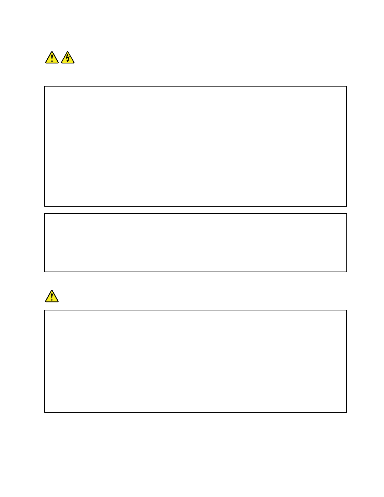
Statement1
DANGER
Electricalcurrentfrompower,telephone,andcommunicationcablesishazardous.
Toavoidashockhazard:
•Donotconnectordisconnectanycablesorperforminstallation,maintenance,orreconfigurationofthis
productduringanelectricalstorm.
•Connectallpowercordstoaproperlywiredandgroundedelectricaloutlet.
•Ensurethatallpowercordconnectorsaresecurelyandcompletelypluggedintoreceptacles.
•Connecttoproperlywiredoutletsanyequipmentthatwillbeattachedtothisproduct.
•Whenpossible,useonehandonlytoconnectordisconnectsignalcables.
•Neverturnonanyequipmentwhenthereisevidenceoffire,water,orstructuraldamage.
•Disconnecttheattachedpowercords,telecommunicationssystems,networks,andmodemsbeforeyou
openthedevicecovers,unlessinstructedotherwiseintheinstallationandconfigurationprocedures.
•Connectanddisconnectcablesasdescribedinthefollowingtablewheninstalling,moving,oropening
coversonthisproductorattacheddevices.
Toconnect:Todisconnect:
1.TurneverythingOFF .
2.First,attachallcablestodevices.
3.Attachsignalcablestoconnectors.
4.Attachpowercordstooutlet.
5.TurndevicesON.
1.TurneverythingOFF .
2.First,removepowercordsfromoutlet.
3.Removesignalcablesfromconnectors.
4.Removeallcablesfromdevices.
Statement2
DANGER
Dangerofexplosionifbatteryisincorrectlyreplaced.
Whenreplacingthelithiumcoincellbattery,useonlythesameoranequivalenttypethatis
recommendedbythemanufacturer .Thebatterycontainslithiumandcanexplodeifnotproperly
used,handled,ordisposedof.
Donot:
•Throworimmerseintowater
•Heattomorethan100°C(212°F)
•Repairordisassemble
Disposeofthebatteryasrequiredbylocalordinancesorregulations.
©CopyrightLenovo2014
v
Page 8
Statement3
CAUTION:
Whenlaserproducts(suchasCD-ROMs,DVDdrives,fiberopticdevices,ortransmitters)are
installed,notethefollowing:
•Donotremovethecovers.Removingthecoversofthelaserproductcouldresultinexposureto
hazardouslaserradiation.Therearenoserviceablepartsinsidethedevice.
•Useofcontrolsoradjustmentsorperformanceofproceduresotherthanthosespecifiedherein
mightresultinhazardousradiationexposure.
DANGER
SomelaserproductscontainanembeddedClass3AorClass3Blaserdiode.Notethefollowing:
Laserradiationwhenopen.Donotstareintothebeam,donotviewdirectlywithoptical
instruments,andavoiddirectexposuretothebeam.
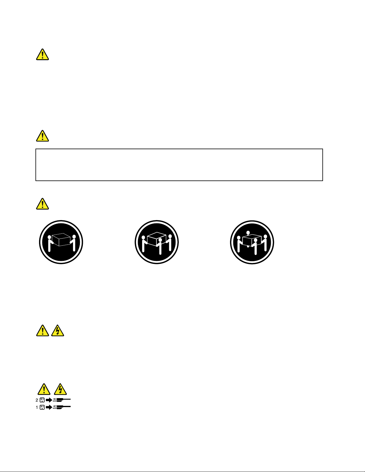
Statement4
≥18kg(39.7lb)≥32kg(70.5lb)≥55kg(121.2lb)
<32kg(70.5lb)<55kg(121.2lb)<100kg(220.5lb)
CAUTION:
Usesafepracticeswhenlifting.
Statement5
CAUTION:
Thepowercontrolbuttononthedeviceandthepowerswitchonthepowersupplydonotturnoff
theelectricalcurrentsuppliedtothedevice.Thedevicealsomighthavemorethanonepower
cord.Toremoveallelectricalcurrentfromthedevice,ensurethatallpowercordsaredisconnected
fromthepowersource.
viThinkServerRS140UserGuideandHardwareMaintenanceManual
Page 9
Statement6
CAUTION:
Ifyouinstallastrain-reliefbracketoptionovertheendofthepowercordthatisconnectedtothe
device,youmustconnecttheotherendofthepowercordtoapowersourcethatiseasilyaccessible
incaseitneedstobedisconnected.
Statement7
CAUTION:
Ifthedevicehasdoors,ensurethatyouremoveorsecurethedoorsbeforemovingorliftingthe
devicetoprotectagainstpersonalinjury.Thedoorswillnotsupporttheweightofthedevice.
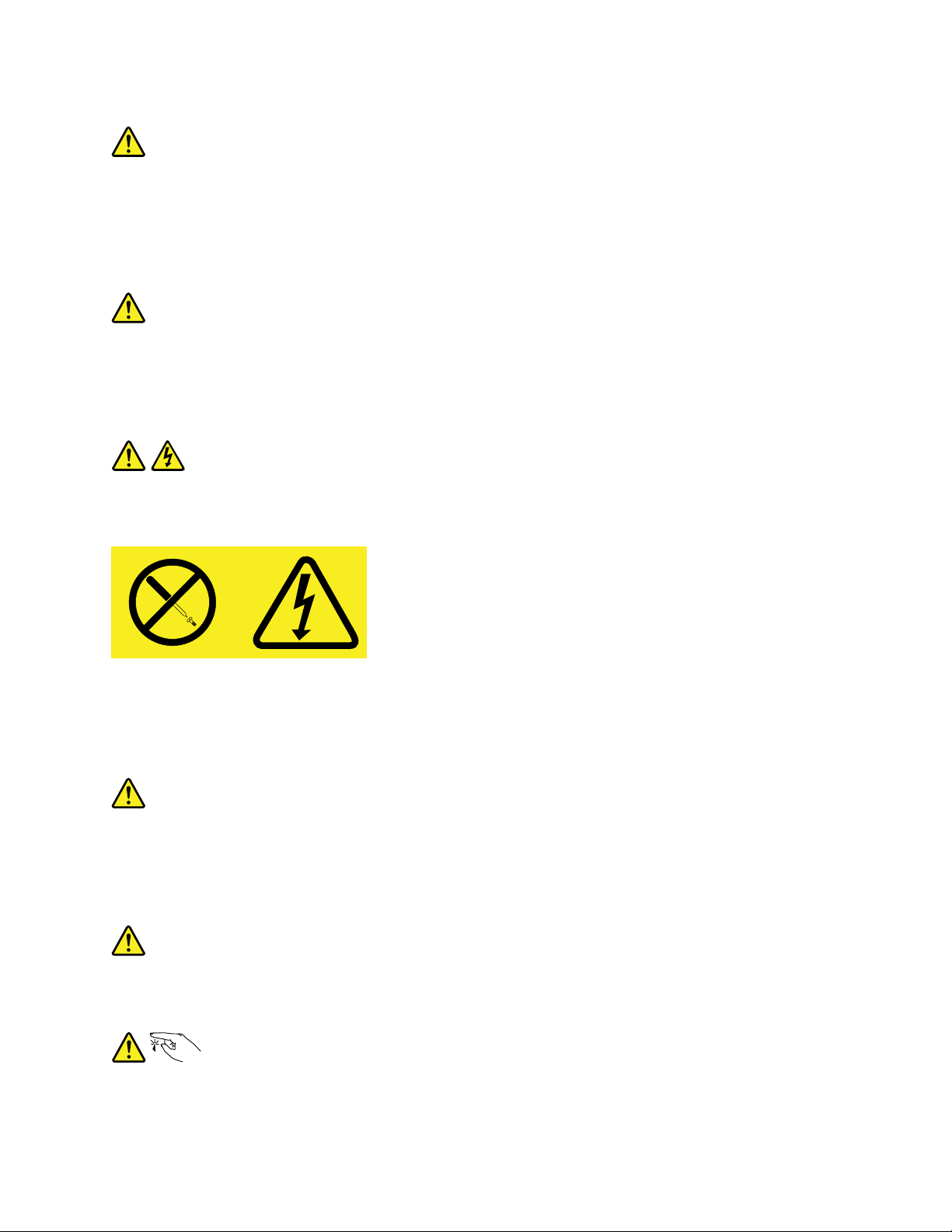
Statement8
CAUTION:
Neverremovethecoveronapowersupplyoranypartthathasthefollowinglabelattached.
Hazardousvoltage,current,andenergylevelsarepresentinsideanycomponentthathasthislabel
attached.Therearenoserviceablepartsinsidethesecomponents.Ifyoususpectaproblemwith
oneoftheseparts,contactaservicetechnician.
Statement9
CAUTION:
Disconnectthehot-swapfancablesbeforeremovingthefanfromthedevicetoprotectagainst
personalinjury.
Statement10
CAUTION:
Thefollowinglabelindicatesasharp-edgehazard.
©CopyrightLenovo2014
vii
Page 10
Statement11
CAUTION:
Thefollowinglabelindicatesapotentialheathazard.
Statement12
DANGER
Overloadingabranchcircuitisapotentialfirehazardandashockhazardundercertainconditions.To
avoidthesehazards,ensurethatyoursystemelectricalrequirementsdonotexceedbranchcurrentratings
attheinstallationsite.
Statement13
CAUTION:
Ensurethattherackissecuredproperlytoavoidtippingwhentheserverunitisextendedontherails.
Statement14
CAUTION:
SomeaccessoryoroptionboardoutputsexceedClass2orlimitedpowersourcelimits.Y ou
mustinstalltheappropriateinterconnectingcablinginaccordancewithyourlocalelectricalcode
requirements.
Statement15
CAUTION:
Thepower-controlbuttononthedevicemayputthedeviceinstandbymodeinsteadofturningoff
thedevice.Inaddition,thedevicemighthavemultipleconnectionstodcpower.T oremoveall
electricalcurrentfromthedevice,ensurethatallconnectionstodcpoweraredisconnectedat
thedcpowerinputterminals.
viiiThinkServerRS140UserGuideandHardwareMaintenanceManual
Page 11
Statement16
CAUTION:
Toreducetheriskofelectricshockorenergyhazards:
•Thisequipmentmustbeinstalledbytrainedservicepersonnelinarestricted-accesslocation,as
definedbyyourlocalelectricalcodeandthelatesteditionofIEC60950.
•Connecttheequipmenttoareliablyearthedsafetyextralowvoltage(SELV)source.AnSELV
sourceisasecondarycircuitthatisdesignedsothatnormalandsinglefaultconditionsdonot
causethevoltagestoexceedasafelevel(60Vdirectcurrent).
•Thebranchcircuitovercurrentprotectionmustberatedinaccordancewithlocalelectricalcode
requirements.
•Use1.3mm
2
or16AmericanWireGauge(AWG)copperconductoronly,notexceeding3meters
inlength.
•Torquethewiring-terminalscrewsto1.4newton-metersor12inch-pounds.
•Provideareadilyavailable,approvedandrateddisconnectdeviceinthefieldwiring.
Statement17
CAUTION:
ThisproductcontainsaClass1Mlaser.Donotviewdirectlywithopticalinstruments.
Statement18
CAUTION:
Donotplaceanyobjectontopofrack-mountedproducts.
Statement19
CAUTION:
Hazardousmovingparts.Keepfingersandotherbodypartsaway.
©CopyrightLenovo2014
ix
Page 12
Statement20
CAUTION:
Alithiumionbatteryisprovided.Toavoidpossibleexplosion,donotburnthebattery.Replacethe
batteryonlywiththeLenovo-approvedpart.Recycleordiscardthebatteryasinstructedbylocal
regulations.
Statement21
Attention:ChooseonlyD40oraboveair-breakswitchtoavoidunexpectedpoweroutage.
Productsthatarenotassessed
Typicalproductsthatarenotassessedincludebutnotlimitedtothefollowing:
•ServerandIT-rackcomponents(forexample,uninterruptiblepowersuppliesandcurrentdistribution
systems)
•DevicesinITrooms(forexample,bulkstorageunitsandnetworkproducts)
•Industriallow-voltageswitchgear
xThinkServerRS140UserGuideandHardwareMaintenanceManual
Page 13

Chapter1.Generalinformation
Thischapterprovidessomegeneralinformationaboutyourproduct.
Thischaptercontainsthefollowingitems:
•“Introduction”onpage1
•“Serverdocumentation”onpage2
Introduction
ThisdocumentationforyourLenovo
specifications,componentlocations,configurationinstructions,hardwarereplacementprocedures,and
basictroubleshootinganddiagnostics.
YourservercomeswithadocumentationDVDthatcontainsvariousserverdocumentstohelpyouuseand
maintaintheserver.Meanwhile,yourservercomeswithaThinkServerEasyStartupDVDthatprovidesa
convenientsolutionforconfiguringtheserverandinstallinganoperatingsystem.
TheLenovoLimitedWarranty(LLW)containsthewarrantytermsthatapplytotheproductyoupurchasedfrom
Lenovo.ReadtheLLWonthedocumentationDVDthatcomeswithyourserver.Aprintablegenericversion
ofthelatestLLWalsoisavailableinmorethan30languagesathttp://www.lenovo.com/warranty/llw_02.If
youcannotobtaintheLLWthroughthedocumentationDVDorLenovoWebsite,contactyourlocalLenovo
officeorresellertoobtainaprintedversionoftheLLW,freeofcharge.
®
ThinkServer
®
productcontainsinformationabouttheserverfeatures,
Forwarrantyservice,consulttheworldwideLenovoSupporttelephonelist.Telephonenumbersaresubject
tochangewithoutnotice.Themostup-to-datetelephonelistforLenovoSupportisalwaysavailableonthe
Websiteathttp://www.lenovo.com/support/phone.Ifthetelephonenumberforyourcountryorregionisnot
listed,contactyourLenovoresellerorLenovomarketingrepresentative.
Toobtainthemostup-to-dateinformationabouttheserver,goto:
http://www.lenovo.com/thinkserver
LenovomaintainspagesontheWorldWideWeb,whereyoucangetthelatesttechnicalinformationand
downloaddocumentationordevicedriversandupdates.T oaccesstheLenovoSupportWebsite,goto:
http://www.lenovo.com/support
©CopyrightLenovo2014
1
Page 14

Recordinformationaboutyourserverinthefollowingtable.Youwillneedtheinformationifyoueverneed
tohaveyourserverserviced.
Forwheretofindtheproductinformationlabelonthechassis,see“Machinetype,model,andserialnumber
label”onpage11
.
Productname
Machinetypeandmodel(MT-M)
Serialnumber(S/N)
Dateofpurchase
______________________________________________
______________________________________________
______________________________________________
______________________________________________
YoucanregisteryourserverwithLenovobyfollowingtheinstructionsat:
http://www.lenovo.com/register
Whenyouregisteryourserver,informationisenteredintoadatabase,whichenablesLenovotocontact
youincaseofarecallorothersevereproblem.AfteryouregisteryourserverwithLenovo,youwillreceive
quickerservicewhenyoucallLenovoforhelp.Inaddition,somelocationsofferextendedprivilegesand
servicestoregisteredusers.
Serverdocumentation
Thistopicprovidesgeneraldescriptionsofthevariousdocumentationforyourserverandinstructionson
howtoobtainallthedocumentation.
Printeddocument
Thefollowingdocumentisprintedoutandcontainedinyourserverpackage.
ReadMeFirst
Thisisamultilingualdocumentyoushouldreadfirst.Thisdocumentguidesyoutoreadthecomplete
warranty,support,andsafetyinformationonthedocumentationDVDthatcomeswithyourserverbefore
usingtheproduct.Thisdocumentalsoprovidesinformationabouthowtofindthemostup-to-date
informationontheLenovoSupportWebsite.
DocumentationDVD
ThedocumentationDVD,whichcomeswithyourserver,containsvariousdocumentsforyourserverin
PortableDocumentFormat(PDF)andHyperTextMarkupLanguage(HTML).ThedocumentationDVDisnot
bootable.ToviewthedocumentsontheDVD,youwillneedacomputerwithaWebbrowserandtheAdobe
Readerprogram,whichisavailablefordownloadat:
http://www.adobe.com
TostartthedocumentationDVD,inserttheDVDintotheopticaldrive.TheDVDisAutoPlayenabledand
startsautomaticallyinmostMicrosoft
®
Linux
operatingsystem,openthelaunch.htmfilelocatedintherootdirectoryoftheDVD.
®
Windows
®
environments.IftheDVDfailstostartorifyouareusinga
2ThinkServerRS140UserGuideandHardwareMaintenanceManual
Page 15

Note:LenovomaintainspagesontheWorldWideWeb,whereyoucangetthelatesttechnicalinformation
anddownloaddocumentationordevicedriversandupdates.Someinformationinthedocumentsonthe
documentationDVDmightchangewithoutnoticeafterthefirstreleaseoftheDVD.Y oucanalwaysobtainall
themostup-to-datedocumentationforyourserverfromtheLenovoWebsiteat:
http://www.lenovo.com/UserManuals
ThefollowingdocumentsareonthedocumentationDVDthatcomeswithyourserver:
•Safety,Warranty,andSupportInformation
Thisisamultilingualdocumentthatincludesallthesafetystatementsforyourproductinmorethan30
languages.Besuretoreadandunderstandallthesafetystatementsbeforeusingtheproduct.This
documentalsoincludestheLenovowarrantystatement,CustomerReplaceableUnits(CRUs)information,
andinformationabouthowtocontacttheLenovoCustomerSupportCenter.
•LenovoLicenseAgreement
ThisdocumentincludesthetermsandconditionsoftheLenovoLicenseAgreement.
•UserGuideandHardwareMaintenanceManual
Thisdocumentprovidesdetailedinformationtohelpyougetfamiliarwithyourserverandhelpyou
use,configure,andmaintainyourserver.Someinformationinthisdocument,ifspecified,isintended
forservicetechniciansonly.
•MegaRAIDSASSoftwareUserGuide
ThisdocumentprovidesinformationaboutRedundantArrayofIndependentDisks(RAID)andhowto
usetheutilityprogramstoconfigure,monitor,andmaintainyourserverRAIDandrelateddevices.This
documentisinEnglishonly.
Note:RefertothisdocumentforhardwareRAIDinformationifyouhavearequiredRAIDcardinstalledin
theserver.See“InstallingorremovingtheRAIDcard”onpage62
.
Chapter1.Generalinformation3
Page 16

4ThinkServerRS140UserGuideandHardwareMaintenanceManual
Page 17

Chapter2.Serversetuproadmap
Thischapterprovidesageneralroadmaptoguideyouthroughsettingupyourserver.
Theserversetupprocedurevariesdependingontheconfigurationoftheserverwhenitwasdelivered.In
somecases,theserverisfullyconfiguredandyouneedtoconnecttheservertothenetworkandanacpower
source,andthenyoucanturnontheserver.Inothercases,theserverneedstohavehardwaredevices
installed,requireshardwareandfirmwareconfiguration,andrequiresanoperatingsystemtobeinstalled.
Thegeneralprocedureforsettingupyourserveris:
1.Unpacktheserverpackage.See“Serverpackage”onpage7.
2.Installanyrequiredhardwareorserveroptions.SeetherelatedtopicsinChapter6“Installing,removing,
orreplacinghardware”onpage53.
3.Ifyouhavearailkit,youcaninstalltheserverintoastandardrackcabinet.Seethedocumentation
thatcomeswiththerailkit.
4.ConnecttheEthernetcablesandthepowercordtotheserver.See“Rearviewoftheserver”onpage
14tolocatetheconnectors.
5.Turnontheservertoverifyoperation.See“Turningontheserver”onpage35.
6.ReviewtheUnifiedExtensibleFirmwareInterface(UEFI)BasicInputOutputSystem(BIOS)settingsand
customizeasneeded.See“UsingtheSetupUtilityprogram”onpage37.
7.ConfigureRAIDandinstalltheoperatingsystemanddevicedrivers.See“UsingtheThinkServer
EasyStartupprogram”onpage44and“ConfiguringRAID”onpage47.
8.Installanyadditionaldriversrequiredforaddedfeatures.Refertotheinstructionsthatcomewith
thehardwareoption.
9.ConfigureEthernetsettingsintheoperatingsystembyreferringtotheoperatingsystemhelp.Thisstep
isnotrequirediftheoperatingsystemwasinstalledusingtheThinkServerEasyStartupprogram.
10.Checkforfirmwareupdates.See“Updatingthefirmware”onpage52.
11.Installmanagementapplicationsandanyotherapplications.Refertothedocumentationthatcomes
withtheapplicationsthatyouwanttoinstall.
©CopyrightLenovo2014
5
Page 18

6ThinkServerRS140UserGuideandHardwareMaintenanceManual
Page 19
Chapter3.Productoverview
!
ID
Thischapterprovidesinformationabouttheserverpackage,features,specifications,softwareprograms,
andcomponentlocations.
Thischaptercontainsthefollowingitems:
•“Serverpackage”onpage7
•“Features”onpage7
•“Specifications”onpage10
•“Software”onpage11
•“Locations”onpage11
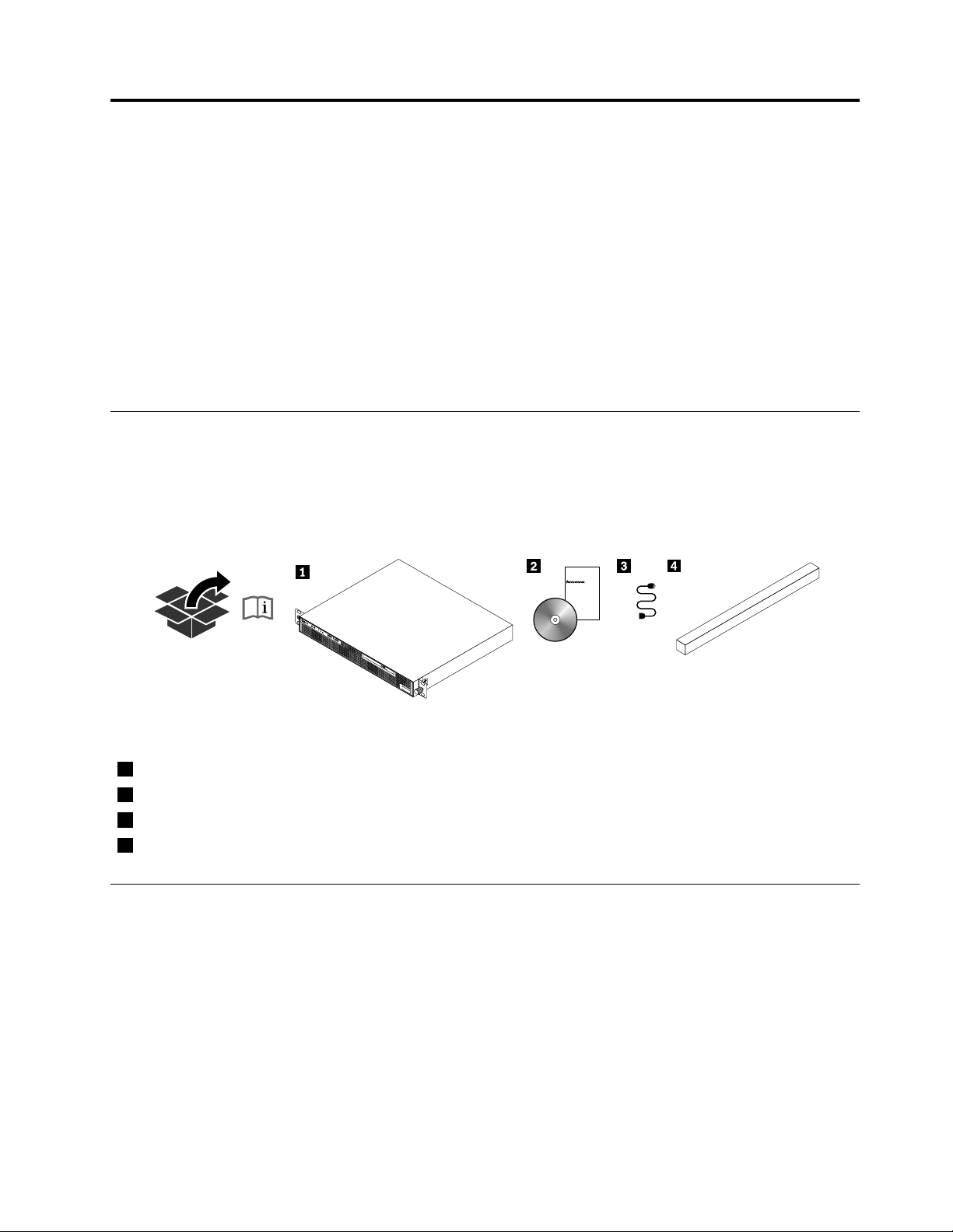
Serverpackage
Theserverpackageincludestheserver,thepowercord,printeddocumentation,adocumentationDVD,and
softwaremedia.
Note:Dependingonthemodel,yourservermightlookslightlydifferentfromthefollowingillustration.
Figure1.Serverpackage
1Server
2Materialbox(includingprinteddocumentation,adocumentationDVD,andsoftwaremedia)
3Powercord
4Railkit
Features
Thistopicprovidesgeneralinformationabouttheserverfeaturesforvariousmodels.Dependingonyour
specificmodel,somefeaturesmightvaryorunavailable.Forinformationaboutyourspecificmodel,usethe
SetupUtilityprogram.See“ViewinginformationintheSetupUtilityprogram”onpage37.Youalsocanrefer
tothePersonalSystemsReferencedocumentforThinkServerproductsat:
http://www.lenovo.com/psref/
©CopyrightLenovo2014
7
Page 20

Microprocessor
Yourservercomeswithoneofthefollowingmicroprocessors(internalcachesizevariesbymodeltype):
•Intel
®
•IntelCore
•IntelPentium
•IntelXeon
Celeron
®
microprocessor
™
i3microprocessor
®
microprocessor
®
microprocessor
ForalistofThinkServermicroprocessoroptions,goto:
http://www.lenovo.com/thinkserver
Memory
Yourserverhasfourmemoryslots.Formoreinformation,see“Memorymoduleinstallationrules”onpage59.
Powersupply
Yourservercomeswitha300-wattautomaticvoltage-sensingpowersupply.
Systemfan
Yourserverhasthreesystemfans.
Internaldrive
Internaldrivesaredevicesthatyourserverusestoreadandstoredata.Theinternaldrivessupported
byyourservervarybymodel.
•Harddiskdrive
–Uptotwo3.5-inchSerialAdvancedTechnologyAttachment(SATA)orSerialAttachedSCSI(SAS)hard
diskdrives(SCSIistheacronymforSmallComputerSystemInterface)
–Uptofour2.5-inchSATAorSASharddiskdrivesorSATAsolid-statedrives
Note:Theterm“2.5-inchharddiskdrives”hereinafterreferstoallthesupportedtypesof2.5-inchhard
diskdrives,includingsolid-statedrives.
•Opticaldrive
OneslimSATAopticaldrive(availableonsomemodels)
Expansionslot
OnePeripheralComponentInterconnect(PCI)Expresscardslotontherisercardassembly
Fordetailedinformation,see“Rearviewoftheserver”onpage14
.
8ThinkServerRS140UserGuideandHardwareMaintenanceManual
Page 21

Input/Output(I/O)features
•FourUSB2.0connectors(twoonthefrontpanelandtwoontherearpanel)
•FourUSB3.0connectorsontherearpanel
•OneDisplayPort®connectorontherearpanel
•Oneserialconnectorontherearpanel
•Onevideographicsarray(VGA)connectorontherearpanel
•ThreeRJ-45Ethernetconnectors(oneontherearpanelforsystemmanagementandtwoontheEthernet
card)
Forthelocationinformationabouttheconnectors,refertotherelatedtopicsin“Locations”onpage11.
Videosubsystem
IntegratedgraphicsforaVGAconnectorandaDisplayPortconnector
Ethernetconnectivity
TherearethreeRJ-45Ethernetconnectorsontherearpanelwith10megabitspersecond(Mbps),100
Mbps,or1000Mbpsnetworkconnectivity.Formoreinformation,see“Rearviewoftheserver”onpage14.
Reliability,availability,andserviceability
Reliability,availability,andserviceability(hereinafterreferredtoasRAS)arethreeimportantserverdesign
features.TheRASfeatureshelpyoutoensuretheintegrityofthedatastoredontheserver,theavailabilityof
theserverwhenyouneedit,andtheeasewithwhichyoucandiagnoseandcorrectproblems.
YourserverhasthefollowingRASfeatures:
•Securityfeatures
–Administratorpasswordanduserpasswordtohelpyouprotectunauthorizedaccesstotheserver
(see“Usingpasswords”onpage41)
–ThinkServerT rustedPlatformModule(TPM),whichisasecuritychip,tohelpenhanceserversecurity
Note:TheTPMisonlyavailableinsomemodels.
–RedundantArrayofIndependentDisks(RAID)configurationforimprovingdatastoragereliabilityand
faulttolerance(see“ConfiguringRAID”onpage47)
–Remotemonitoringorcontrolbyanadministratortoprovideprotectionorhelp
•Basicsystemmanagementfeatures
–Abilitytostorethepower-onself-test(POST)hardwaretestresults
–BIOSSetupUtilityprogram
TheBIOSSetupUtilityprogramhelpsyouviewtheserverinformationandconfiguretheserverinthe
pre-operatingsystemenvironment.See“UsingtheSetupUtilityprogram”onpage37
.
–PrebootExecutionEnvironment(PXE)
TheIntelPXEtechnologyenablesyoutostartyourcomputers,loadanoperatingsystem,ordeploy
executableimagesfromaremoteserverbyusinganetworkinterface.Theoperationcanbedone
independentlyoflocaldatastoragedevices(suchasharddiskdrives)oroperatingsystems.
Chapter3.Productoverview9
Page 22

–RAID
YourserversupportsonboardSATAsoftwareRAID.IfarequiredRAIDcardisinstalled,yourserver
alsosupportsadvancedSATA/SAShardwareRAIDconfigurations.Fordetailedinformation,see
“ConfiguringRAID”onpage47
.
Note:TheonboardRAIDisasoftwareRAIDinsteadofahardwareRAID.
–Softwareprograms
Formoreinformationaboutthesoftwareprograms,see“Software”onpage11
.
–WakeonLAN
WakeonLANisanEthernetcomputernetworkingstandardthatallowsacomputertobeturnedon
orwokenupbyanetworkmessage.Themessageisusuallysentbyaprogramrunningonanother
computeronthesamelocalareanetwork.
Specifications
Thistopicliststhephysicalspecificationsforyourserver.
Dimensions
Widthwithoutrackhandles:430mm(16.9inches)
Depth:411mm(16.2inches)
Height:43.5mm(1.71inches)
Weight
Theproductweightvariesdependingondifferentsystemconfigurations.
Rangeofproductweightwithpackage:11.63kg(25.64lb)to13.16kg(29.01lb)
Environment
•Airtemperature:
Operating:10°Cto35°C(50°Fto95°F)
Storage:-40°Cto70°C(-40°Fto158°F)inoriginalshippingpackage
•Altitude:0to3048m(0to10000ft)inanunpressurizedenvironment
•Humidity:
Operating:10%to80%(non-condensing)
Storagewithoutpackage:10%to80%(non-condensing)
Storagewithpackage:10%to90%(non-condensing)
Electricalinput
•Universalinput:
–Lowrange:
Minimum:100Vac
Maximum:127Vac
Inputfrequencyrange:50to60Hz
–Highrange:
Minimum:200Vac
Maximum:240Vac
Inputfrequencyrange:50to60Hz
10ThinkServerRS140UserGuideandHardwareMaintenanceManual
Page 23

Software
Thistopicprovidesinformationaboutthesoftwareprogramsthatyoucanusetohelpyousetup,use,
andmaintaintheserver.
ThinkServerEasyStartup
TheThinkServerEasyStartupprogramsimplifiestheprocessofconfiguringRAIDandinstallingsupported
MicrosoftWindowsandLinuxoperatingsystems,VMwarehypervisors,anddevicedriversonyourserver.
Thisprogramisprovidedwithyourserveronaself-starting(bootable)ThinkServerEasyStartupDVD.The
userguidefortheprogramalsoisontheDVDandcanbeaccesseddirectlyfromtheprograminterface.For
detailedinformation,see“UsingtheThinkServerEasyStartupprogram”onpage44
.
ThinkServerEasyUpdateFirmwareUpdater
TheThinkServerEasyUpdateFirmwareUpdaterprogram(hereinafterreferredtoastheFirmwareUpdater
program)enablesyoutomaintainyourserverfirmwareup-to-dateandhelpsyouavoidunnecessaryserver
outages.TheFirmwareUpdaterprogramisprovidedontheLenovoSupportWebsite.Formoreinformation
aboutdownloadingandusingtheFirmwareUpdaterprogram,see“Updatingthefirmware”onpage52
.
BIOSupdateutility
TheBIOSfirmwarekeepsupdatingaftertheshipmentoftheserver.LenovomaintainspagesontheSupport
WebsiteandprovidestheBIOSupdateutilitywithinstructionsfordownloadtohelpyouupdatethe
BIOSfirmwareifneeded.Formoreinformation,see“UpdatingorrecoveringtheBIOS”onpage43and
“Updatingthefirmware”onpage52
.
RAIDconfigurationutilities
YourserversupportsonboardSATAsoftwareRAID.IfarequiredRAIDcardisinstalled,yourserveralso
supportsadvancedSATA/SAShardwareRAIDconfigurations.Fordetailedinformation,see“Configuring
RAID”onpage47
.
Diagnosticprograms
Thefollowingdiagnosticprogramsareavailableforyoutodiagnoseserverproblems:
•ThinkServerDiagnosticTool
•ThinkServerSystemProfileCollectionT ool
Formoreinformation,see“Usingadiagnosticprogram”onpage111.
Locations
Thistopicprovidesinformationtohelpyoulocateyourservercomponents.
Machinetype,model,andserialnumberlabel
Thistopichelpsyoulocatethelabelthatcontainsthemachinetype,model,andserialnumberinformation
foryourserver.
WhenyoucontactLenovoforhelp,themachinetype,model,andserialnumberinformationhelpssupport
technicianstoidentifyyourserverandprovidefasterservice.
Chapter3.Productoverview11
Page 24
Themachinetype,model,andserialnumberlabelisattachedontherightrackhandleofyourserveras
!
ID
MT-M XXXX-XXX
S / N XXXXXXX
!
ID
shown.
Note:Dependingonthemodeltype,yourservermightlookslightlydifferentfromthisillustration.
Figure2.Machinetype,model,andserialnumberlabel
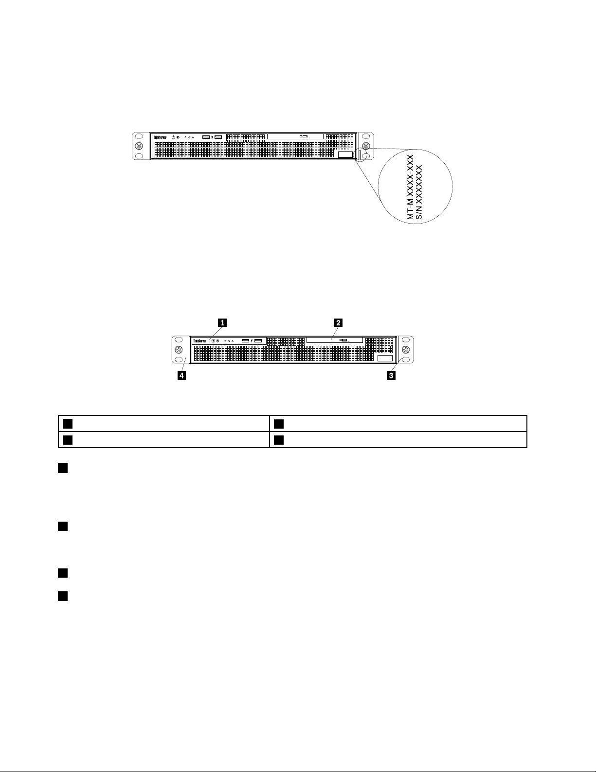
Frontviewoftheserver
Thefollowingillustrationshowsthefrontviewoftheserver.
Figure3.Frontviewoftheserver
1Frontpanel
3Rackhandle(right)4Rackhandle(left)
1Frontpanel
2Slimopticaldrive(availableonsomemodels)
Fordetailedinformationaboutthecontrols,connectors,andstatusLEDsonthefrontpanel,see“Front
panel”onpage13
2Slimopticaldrive
.
SomeservermodelscomewithaslimSATAopticaldrive.
3Rackhandle(right)
4Rackhandle(left)
Ifyourserverisinstalledinarackcabinet,youcanusetherackhandlestohelpyouslidetheserveroutof
therackcabinet.Youalsocanusetherackhandlesandscrewstosecuretheserverintherackcabinet
sothattheservercannotslideout,especiallyinvibration-proneareas.Formoreinformation,refertothe
documentationthatcomeswithyourrailkit.
12ThinkServerRS140UserGuideandHardwareMaintenanceManual
Page 25
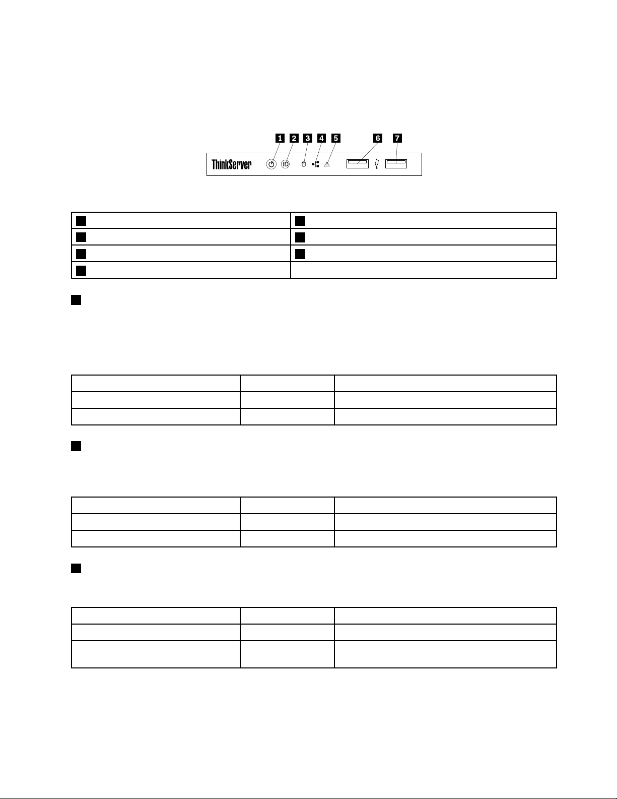
Frontpanel
!
ID
Thefollowingillustrationshowsthecontrols,connectors,andLEDsonthefrontpaneloftheserver.Tolocate
thefrontpanel,see“Frontviewoftheserver”onpage12.
Figure4.Frontpanel
1PowerbuttonwithpowerstatusLED2IDbuttonwithIDLED
3Hard-disk-drivestatusLED
5SystemerrorLED6FrontUSB2.0connector1
7FrontUSB2.0connector2
1PowerbuttonwithpowerstatusLED
Pressthepowerbuttontoturnontheserverwhenyoufinishsettinguptheserver.Holdthepowerbutton
forseveralsecondstoturnofftheserverifyoucannotturnitofffromtheoperatingsystem.SeeChapter
4“Turningonandturningofftheserver”onpage35.ThepowerstatusLEDhelpsyoutodeterminethe
currentpowerstatus.
4NetworkInterfaceController(NIC)statusLED
PowerstatusLED
2IDbuttonwithIDLED
OnGreen
Off
Color
Theserverison.
None
Theserverisoff.
Description
WhenyoupresstheIDbuttononthefrontpanel,theIDLEDsonboththefrontandrearoftheserverarelit
tohelpyoulocatetheserveramongotherservers.
IDLED
On
Off
3Hard-disk-drivestatusLED
Color
Blue
None
Theserverisidentified.
TheIDLEDisnotinuseortheserverisnotidentified.
Description
Thehard-disk-drivestatusLEDhelpsyoutodeterminetheactivityoftheharddiskdrive.
Hard-disk-drivestatusLED
Off
Blinking
Color
NoneTheharddiskdriveisnotinuse.
Green
Theharddiskdriveisactiveanddataisbeing
transferred.
Description
Chapter3.Productoverview13
Page 26
4 NICstatusLED
TheNICstatusLEDindicatestheLANstatusfortheEthernetconnector1andEthernetconnector2onthe
rearpaneloftheserver.
Description
5 S
ystemerrorLED
NICstatusLEDColor
OnGreen
Off
Blinking
TheserverisconnectedtoaLAN.
None
Green
TheserverisdisconnectedfromaLAN.
TheLANisconnectedandactive.
ThesystemerrorLEDhelpsyoutodetermineifthereareanysystemerrors.
S
ystemerrorLEDColor
OnGreenThebootingprocessstopsbecauseofaPOSTerror.
Off
6 FrontUSB2.0connector1
7 FrontUSB2.0connector2
None
Theserverisoffortheserverisonandworking
correctly.
Description
UsedtoattachaUSB-compatibledevice,suchasaUSBkeyboard,mouse,scanner,orprinter.Ifyouhave
morethaneightUSBdevices,youcanpurchaseaUSBhub,whichyoucanusetoconnectadditional
USBdevices.
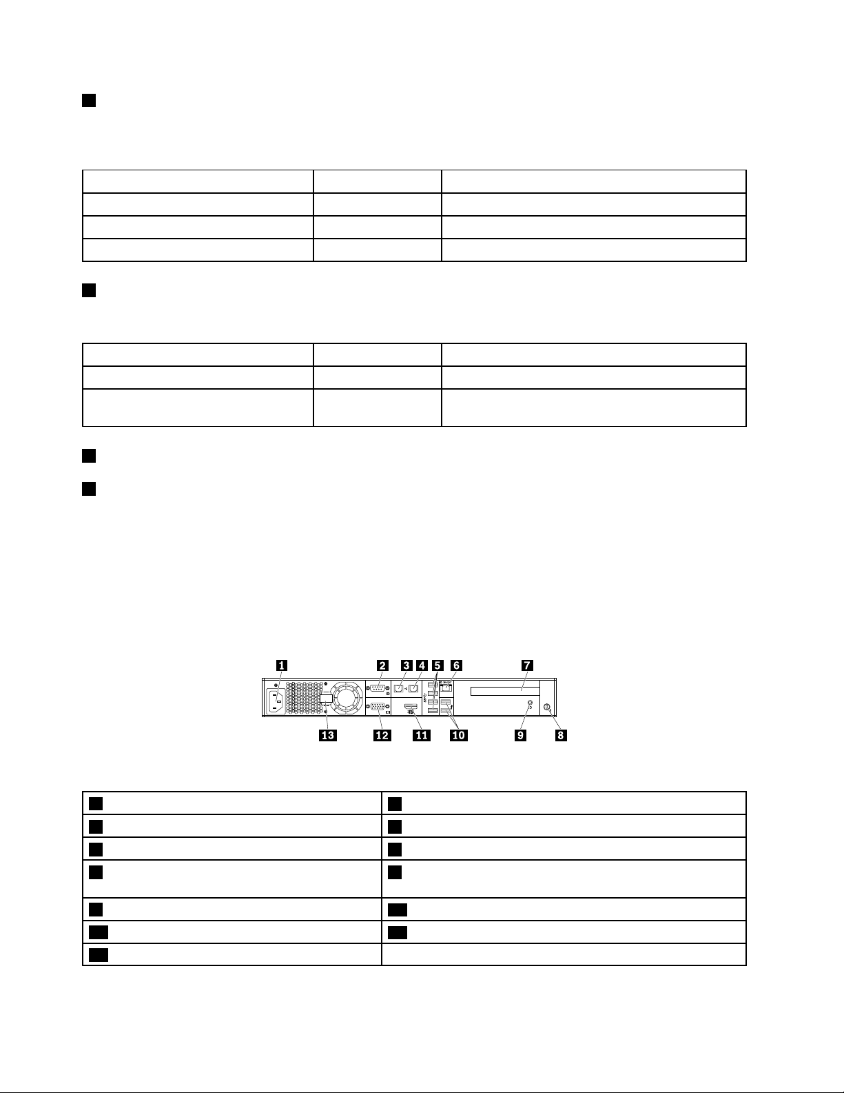
Rearviewoftheserver
Thefollowingillustrationshowstherearviewoftheserver.
Figure5.Rearviewoftheserver
1 Powercordconnector
Ethernet connector 1 (RJ-45)
3
5 USB3.0connectors(4) 6 Ethernetconnector0forsystemmanagement(RJ-45)
7 PCIExpresscardslotforthecardinstalledon
therisercardassembly
9 IDLED
11 DisplayPortconnector
13 Powercordretainer
2 Serialconnector
Ethernet connector 2 (RJ-45)
4
8 Security-lockslot
USB 2.0 connectors (2)
10
12 VGADB-15connector
14ThinkServerRS140UserGuideandHardwareMaintenanceManual
Page 27
1Powercordconnector
Usedtoconnectthepowercord.
2Serialconnector
Usedtoattachadevicethatusesa9-pinserialconnector.
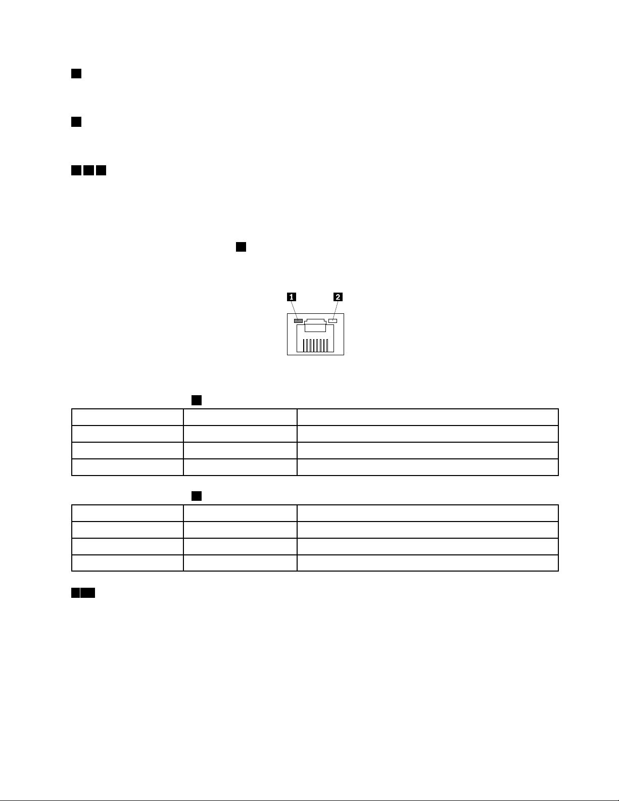
346Ethernetconnectors(RJ-45)
UsedtoattachanEthernetcableforaLAN.EachEthernetconnectorhastwostatusLEDstohelpyou
identifytheEthernetconnectivity,activity,andconnectionspeed.
Notes:
•TheEthernetconnector0(callout6)markedwith“MGMT”isforsystemmanagementbydefault.
•TheEthernetconnector0doesnotsupporttheIntelVirtualizationTechnology.
Figure6.EthernetstatusLEDs
Table1.EthernetstatusLED1
ColorStatus
Amber
GreenOn
None
Table2.EthernetstatusLED2
ColorStatus
Amber
Amber
AmberBlinkingTheLANisconnectedandactive.
510USBconnectors
On
Off
On
Off
Theconnectionspeedis1000Mbps.
Theconnectionspeedis100Mbps.
Theconnectionspeedis10Mbps.
TheserverisconnectedtoaLAN.
TheserverisdisconnectedfromaLAN.
Description
Description
UsedtoattachaUSB-compatibledevice,suchasaUSBkeyboard,mouse,scanner,orprinter.Ifyouhave
morethaneightUSBdevices,youcanpurchaseaUSBhub,whichyoucanusetoconnectadditional
USBdevices.
Chapter3.Productoverview15
Page 28
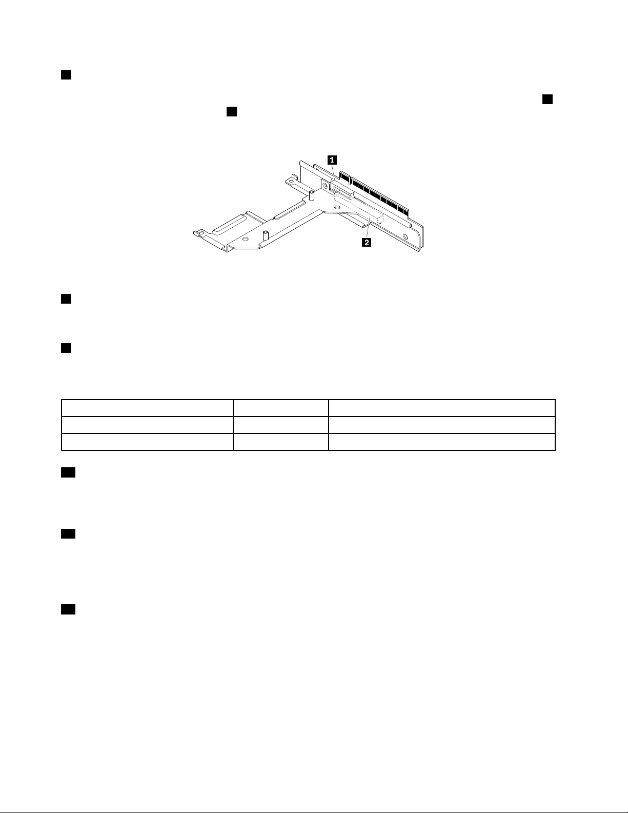
7 PCIExpresscardslot
TherearetwoPCIExpresscardslotsontherisercardassembly.TheEthernetcardisinstalledintheslot
ontherisercardassembly.Theslot 2 isusedtoinstallahalf-length,full-heightPCIExpresscard,suchasa
RAIDcardoraThinkServerHostBusAdapter(HBA).
Figure7.Locatingtheslotsontherisercardassembly
8 Security-lockslot
Usedtoattachacablelocktosecureyourservertoadesk,table,orothernon-permanentfixture.
9 IDLED
WhenyoupresstheIDbuttononthefrontoftheserver,theIDLEDsonboththefrontandrearoftheserver
arelittohelpyoulocatetheserveramongotherservers.
1
IDLED
On
Off
11 DisplayPortconnector
Color
Blue
None
Theserverisidentified.
TheIDLEDisnotinuseortheserverisnotidentified.
Description
Usedtoattachahigh-performancemonitor,adirect-drivemonitor,orotherdevicesthatuseaDisplayPort
connector.
12 VGADB-15connector
UsedtoattachaVGA-compatiblevideodevice,suchasaVGAmonitor.
Note: To connect a VGA cable to this connector, the physical thickness of the whole connector on the end of the VGA
cable must be less than 17 mm (0.67 inch).
13 Powercordretainer
Usedtosecurethepowercord.
16ThinkServerRS140UserGuideandHardwareMaintenanceManual
Page 29
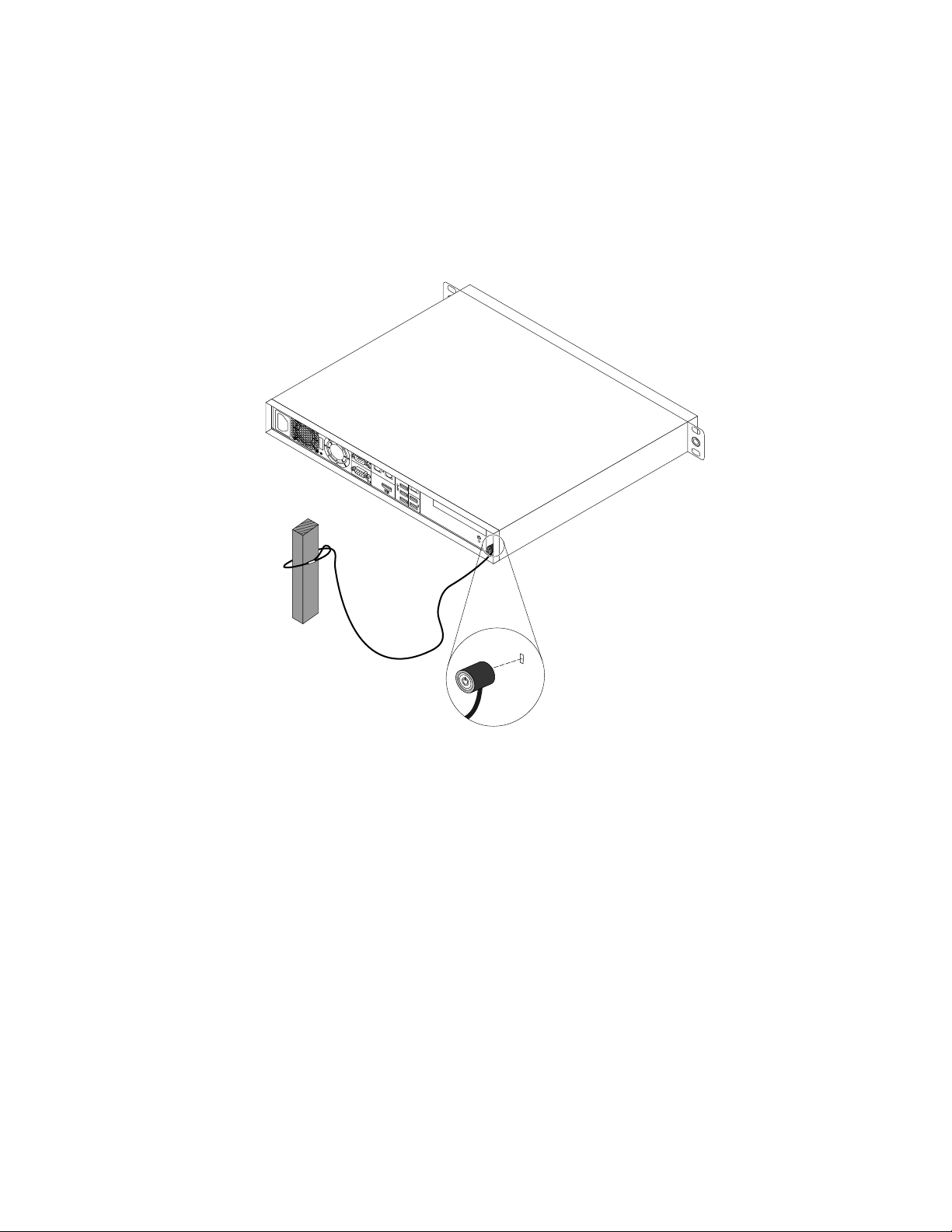
Serverlock
YoucanuseaKensington-stylecablelocktosecureyourservertoadesk,table,orothernon-permanent
fixture.Thecablelockattachestothesecurity-lockslotattherearofyourserverandisoperatedwithakey
orcombinationdependingonthetypeselected.Thecablelockalsolockstheservercover.Thisisthesame
typeoflockusedwithmanynotebookcomputers.YoucanordersuchacablelockdirectlyfromLenovoby
searchingforKensingtonat:
http://www.lenovo.com/support
Figure8.Kensington-stylecablelock
Servercomponents
Thistopicprovidesinformationtohelpyoulocatethecomponentsofyourserver.Formoreinformation
aboutmajorcomponents,seetherelatedtopicsin“Locations”onpage11
Toremovetheservercoverandgainaccesstotheinsideoftheserver,see“Removingtheservercover”
onpage55
Thechassisconfigurationvariesbymodel.Thefollowingillustrationsshowthetwochassisconfigurations
basedonthesupportedharddiskdrives.
•“Componentsofservermodelswithtwo3.5-inchhard-disk-drivebays”onpage18
•“Componentsofservermodelswithfour2.5-inchhard-disk-drivebays”onpage19
Note:Dependingonthemodel,yourservermightlookslightlydifferentfromtheillustrationsinthistopic.
.
.
Chapter3.Productoverview17
Page 30
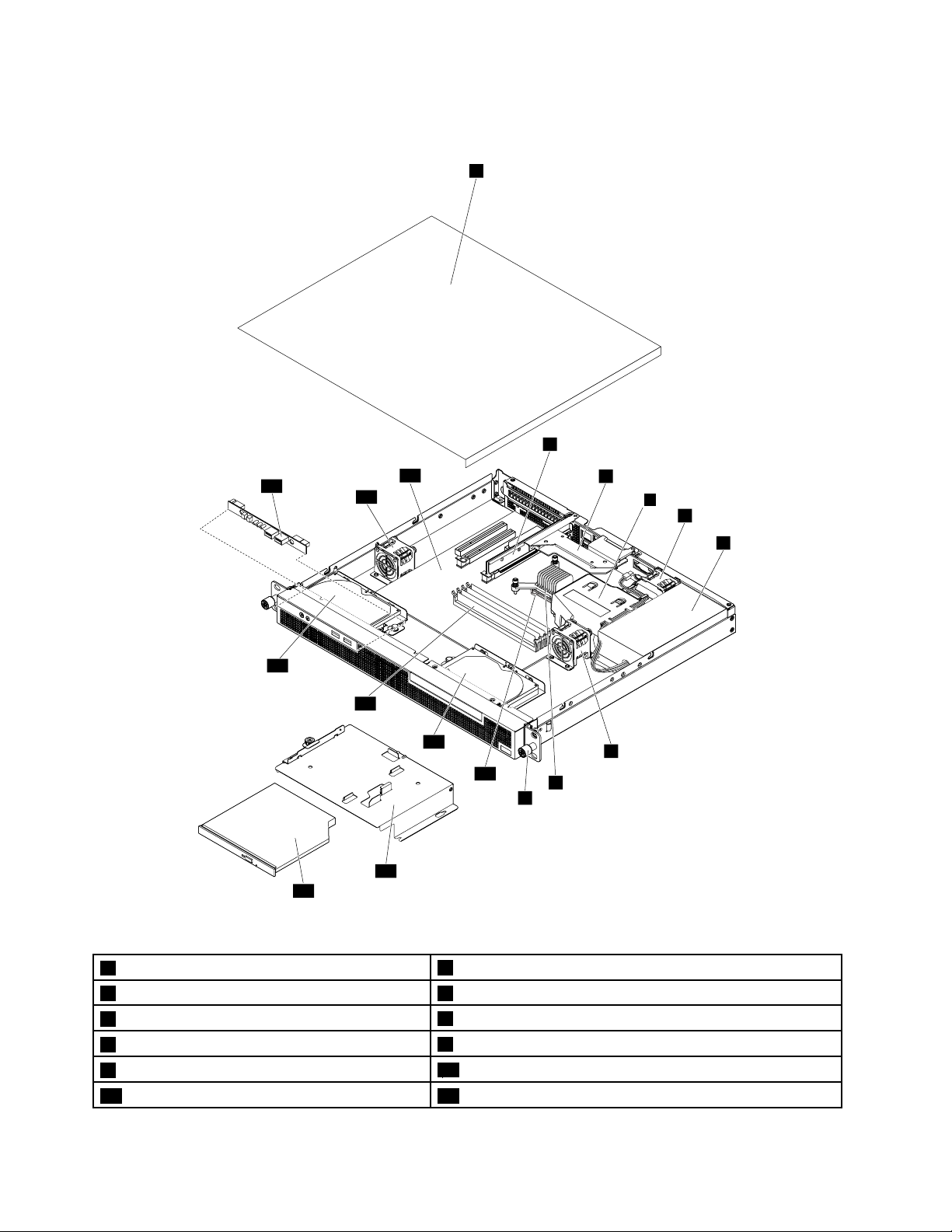
Componentsofservermodelswithtwo3.5-inchhard-disk-drivebays
1
6
8
4
3
2
5
7
17
9
13
10
11
12
14
15
18
16
Figure9.Componentsofservermodelswithtwo3.5-inchhard-disk-drivebays
1Servercover
3Ethernetcard4Fanduct
5Systemfan1
7Systemfan3
9Rackhandle(right)
11Slim-optical-drivebracket12Slimopticaldrive
2Risercardassembly
6Powersupplyassembly
8Heatsink
10Microprocessor
18ThinkServerRS140UserGuideandHardwareMaintenanceManual
Page 31

13Harddiskdrive114Memorymodules
1
6
4
3
2
5
7
19
9
13
14
16
11
12
15
17
20
8
10
18
15Harddiskdrive016Frontpanelboard
17Systemfan218Systemboard
Componentsofservermodelswithfour2.5-inchhard-disk-drivebays
Figure10.Componentsofservermodelswithfour2.5-inchhard-disk-drivebays
1Servercover
3Ethernetcard4Fanduct
2Risercardassembly
Chapter3.Productoverview19
Page 32

5Systemfan1
7Systemfan3
9Rackhandle(right)
11Slim-optical-drivebracket12Slimopticaldrive
132.5-inchharddiskdrive3142.5-inchharddiskdrive2
15Memorymodules162.5-inchharddiskdrive1
172.5-inchharddiskdrive018Frontpanelboard
19Systemfan220Systemboard
6Powersupplyassembly
8Heatsink
10Microprocessor
CRUidentification
CRUsarepartsthatcanbeupgradedorreplacedbythecustomer.IfaCRUisdeterminedtobedefective
duringthewarrantyperiod,areplacementCRUwillbeprovidedtothecustomer.Customersareresponsible
forinstallingtheself-serviceCRUsforthisproduct.Customersalsocaninstalloptional-serviceCRUs,which
mightrequiresometechnicalskillsortools,orrequestthatatechnicianinstalltheoptional-serviceCRU
underthetermsoftheapplicablewarrantyservicetypeforyourcountryorregion.
Non-CRUsmustbereplacedonlybytrainedservicetechnicians.
ThefollowingtableliststhemajorFRUsinyourserverandtheCRUidentificationinformation.Foracomplete
listingofFRUinformation,suchasFRUpartnumbersandsupportedservermodels,goto:
http:/www.lenovo.com/serviceparts-lookup
Notes:
•BeforeservicingaLenovoproduct,ensurethatyoureadandunderstand“Safetyinformation”onpageiii
•UseonlypartsprovidedbyLenovo.
FRUdescription
Coin-cellbattery
EthernetcardYesNo
FanductYesNo
FrontpanelboardNoNo
HarddiskdriveNoNo
HeatsinkYesNo
MemorymoduleYesNo
MicroprocessorNoYes
PCIcard(availableonsomemodels)
PowersupplyassemblyNoYes
RackhandlesYesNo
RisercardassemblyNoYes
Slimopticaldrive(availableonsomemodels)
Systemboard
Systemfan
Self-service
CRU
YesNo
YesNo
YesNo
NoNo
NoNo
Optional-service
CRU
.
20ThinkServerRS140UserGuideandHardwareMaintenanceManual
Page 33

FRUdescription
ThinkServerRAID500UpgradeKeyforAdvancedRAID(availableonsome
models)
ThinkServerRAID700Battery(availableonsomemodels)
Self-service
CRU
YesNo
YesNo
Optional-service
RAIDcard
SomeservermodelscomewithaRAIDcardinstalledinthelongerslotoftherisercardassemblytoprovide
advancedSATA/SAShardwareRAIDfunctions.YoualsocanpurchaseasupportedRAIDcardfromLenovo
andinstallitintotheserver.See“InstallingorremovingtheRAIDcard”onpage62
Note:TheoptionkitforaRAIDcardisdesignedfordifferenttypesofserversandmightcontainadditional
cablesthatarenotrequiredforyourserver.
YourserversupportsthefollowingRAIDcards:
•ThinkServerRAID500Adapter(alsoknownasThinkServer9240-8iRAID0/1Adapter)
•ThinkServerRAID700Adapter(alsoknownasThinkServer9260-8iSASRAIDAdapter)
ThinkServerRAID500Adapter(alsoknownasThinkServer9240-8iRAID0/1Adapter)
ThefollowingillustrationshowstheconnectorsontheThinkServerRAID500Adapter.
.
CRU
Figure11.ThinkServerRAID500Adapter
1Port02Port1
3TR500keyconnector
1Port0
Usedtoconnectamini-SASsignalcable.
2Port1
Usedtoconnectamini-SASsignalcable.
3TR500keyconnector
UsedtoconnectaThinkServerRAID500UpgradeKeyforAdvancedRAID.See“Installingorremovingthe
ThinkServerRAID500UpgradeKeyforAdvancedRAID”onpage66
.
Chapter3.Productoverview21
Page 34

ThinkServerRAID700Adapter(alsoknownasThinkServer9260-8iSASRAIDAdapter)
ThefollowingillustrationshowstheconnectorsontheThinkServerRAID700Adapter.
Figure12.ThinkServerRAID700Adapter
1Ports7-42Ports3-0
3ThinkServerRAID700Batteryconnector
1Ports7-4
Usedtoconnectamini-SASsignalcable.
2Ports3-0
Usedtoconnectamini-SASsignalcable.
3ThinkServerRAID700Batteryconnector
UsedtoconnectaThinkServerRAID700Battery.See“InstallingorremovingtheThinkServerRAID700
Battery”onpage68.
Connectingthecables
Note:YourserversupportsbothSATAandSASharddiskdrives.ForservermodelswithSASharddisk
drives,aRAIDcardmustbeinstalled.ForservermodelswithSATAharddiskdrives,youcanconnectthe
SATAharddiskdrivestoaRAIDcardortheSATAconnectorsonthesystemboard.
Thistopicprovidesinstructionsonthefollowingcableconnections:
•“Connectingthe2.5-inchharddiskdrivesandslimopticaldrivewithaRAIDcard”onpage22
•“Connectingthe2.5-inchharddiskdrivesandslimopticaldrivewithoutaRAIDcard”onpage25
•“Connectingthe3.5-inchharddiskdrivesandslimopticaldrivewithaRAIDcard”onpage27
•“Connectingthe3.5-inchharddiskdrivesandslimopticaldrivewithoutaRAIDcard”onpage29
Connectingthe2.5-inchharddiskdrivesandslimopticaldrivewithaRAIDcard
Note:Ifyouareconnectingthe2.5-inchharddiskdriveswithaThinkServer9207-8i6GHBA,theprocedure
issimilar.
Toconnectthe2.5-inchharddiskdrivesandslimopticaldrivewithaRAIDcard:
22ThinkServerRS140UserGuideandHardwareMaintenanceManual
Page 35

1.Connectthemini-SASconnectorofthemini-SASto2.5-inchSAScombocabletotheRAIDcard.
Note:FortheRAID500Adapter,connectthemini-SASconnectortoPort0.FortheRAID700Adapter,
connectthemini-SASconnectortoPorts3-0.See“RAIDcard”onpage21.
Figure13.Connectingthemini-SASconnectortotheRAIDcard
2.ConnectoneendoftheSAS-hard-disk-drive-LEDcabletothehard-disk-drive-activity-LEDconnector
ontheRAIDcard,ifsupported.
3.InstalltheRAIDcardtotherisercardassembly.See“InstallingtheRAIDcard”onpage62.
4.ConnecttheotherendoftheSAS-hard-disk-drive-LEDcabletothehard-disk-drive-LEDconnectoron
thesystemboard.See“Systemboardcomponents”onpage32
.
Chapter3.Productoverview23
Page 36

5.Dothefollowingtoconnecttheharddiskdrives:
a.12:ConnecttheSATAcomboconnectors0and1ofthemini-SASto2.5-inchSAScombocableto
theharddiskdrives0and1respectively.
b.3:Connectthepowerconnector1ofthemini-SASto2.5-inchSAScombocabletothe4-pinpower
connectorwhichisnearthememorymodulesonthesystemboard.
c.45:ConnecttheSATAcomboconnectors2and3ofthemini-SASto2.5-inchSAScombocableto
theharddiskdrives2and3respectively.
d.6:Connectthepowerconnector2ofthemini-SASto2.5-inchSAScombocabletotheother
available4-pinpowerconnectoronthesystemboard.
Formoreinformation,see“Systemboardcomponents”onpage32.
Figure14.Connectingthe2.5-inchharddiskdrives
6.Ifyouhaveaslimopticaldrive,installtheslim-optical-drivebracket,andtheninstalltheslimoptical
drive.See“Removingandreinstallingtheslim-optical-drivebracket”onpage82and“Installingthe
slimopticaldrive”onpage71
.
24ThinkServerRS140UserGuideandHardwareMaintenanceManual
Page 37

7.Dothefollowingtoconnecttheslimopticaldrive:
a.1:ConnectoneendoftheavailableSATAcabletotheSATA4connectoronthesystemboard.
See“Systemboardcomponents”onpage32.
b.2:ConnecttheotherendoftheSATAcabletotherearoftheslimopticaldrive.
c.3:Connecttheslim-optical-drivepowerconnectorofthemini-SASto2.5-inchSAScombocableto
thepowerconnectorattherearoftheslimopticaldrive.
Note:EnsurethattheSATAcableandthepowercablefortheslimopticaldriveareroutedunderthe
powersupplycableandthemini-SASto2.5-inchSAScombopowercable.
Figure15.Connectingtheslimopticaldrive
8.Routethecablesusingthecabletiesinthechassis.See“Reinstallingtheservercoverandreconnecting
cables”onpage106.
Connectingthe2.5-inchharddiskdrivesandslimopticaldrivewithoutaRAIDcard
Toconnectthe2.5-inchharddiskdrivesandslimopticaldrivewithoutaRAIDcard:
Chapter3.Productoverview25
Page 38

1.Dothefollowingtoconnecttheharddiskdrives:
SATA1 S ATA0 S ATA3
SATA2 S ATA4
a.12:ConnecttheSATAcomboconnectors0and1ofthecomboSAScabletotheharddisk
drives0and1respectively.
b.3:Connectthepowerconnector1ofthecomboSAScabletothe4-pinpowerconnectorwhichis
nearthememorymodulesonthesystemboard.
c.45:ConnecttheSATAcomboconnectors2and3ofthecomboSAScabletotheharddisk
drives2and3respectively.
d.6:Connectthepowerconnector2ofthecomboSAScabletotheotheravailable4-pinpower
connectoronthesystemboard.
Formoreinformation,see“Systemboardcomponents”onpage32.
Figure16.Connectingthe2.5-inchharddiskdrives
2.ConnecttheSATAconnectors0to3ofthecomboSAScabletothecorrespondingSATAconnectors0
to3respectivelyonthesystemboard.See“Systemboardcomponents”onpage32.
Figure17.Connectingthe2.5-inchharddiskdriveSAT Acables
26ThinkServerRS140UserGuideandHardwareMaintenanceManual
Page 39

3.Ifyouhaveaslimopticaldrive,installtheslimslim-optical-drivebracketandtheninstalltheslimoptical
drive.See“Removingandreinstallingtheslim-optical-drivebracket”onpage82and“Installingthe
slimopticaldrive”onpage71.
4.Dothefollowingtoconnecttheslimopticaldrive:
a.1:ConnectoneendoftheavailableSATAcabletotheSATA4connectoronthesystemboard.
See“Systemboardcomponents”onpage32.
b.2:ConnecttheotherendoftheSATAcabletotherearoftheslimopticaldrive.
c.3:Connecttheslim-optical-drivepowerconnectorofacomboSAScabletothepowerconnector
attherearoftheslimopticaldrive.
Note:EnsurethattheSATAcableandthepowercablefortheslimopticaldriveareroutedunderthe
powersupplycableandthecomboSASpowercable.
Figure18.Connectingtheslimopticaldrive
5.Routethecablesusingthecabletiesinthechassis.See“Reinstallingtheservercoverandreconnecting
cables”onpage106.
Connectingthe3.5-inchharddiskdrivesandslimopticaldrivewithaRAIDcard
Note:Ifyouareconnectingthe3.5-inchharddiskdriveswithaThinkServer9207-8i6GHBA,theprocedure
issimilar.
Toconnectthe3.5-inchharddiskdrivesandtheslimopticaldrivewithaRAIDcard:
Chapter3.Productoverview27
Page 40

1.Connectthemini-SASconnectorofthemini-SASto3.5-inchSAScombocabletotheRAIDcard.
Note:FortheRAID500Adapter,connectthemini-SASconnectortoPort0.FortheRAID700Adapter,
connectthemini-SASconnectortoPorts3-0.See“RAIDcard”onpage21.
Figure19.Connectingthemini-SASconnectortotheRAIDcard
2.ConnecttheSAS-hard-disk-drive-LEDcabletothehard-disk-drive-activity-LEDconnectoronthe
RAIDcard,ifsupported.
3.InstalltheRAIDcardtotherisercardassembly.See“InstallingtheRAIDcard”onpage62.
4.ConnecttheotherendoftheSAS-hard-disk-drive-LEDcabletothehard-disk-drive-LEDconnectoron
thesystemboard.See“Systemboardcomponents”onpage32.
5.Dothefollowingtoconnecttheharddiskdrives:
a.1:ConnecttheSATAcomboconnector0ofthemini-SASto3.5-inchSAScombocabletothe
harddiskdrive0.
b.2:Connectthepowerconnectorofthemini-SASto3.5-inchSAScombocabletothe4-pinpower
connectorwhichisnearthememorymodulesonthesystemboard.
c.3:ConnecttheSATAcomboconnector1ofthemini-SASto3.5-inchSAScombocabletothe
harddiskdrive1.
d.4:Connecttheotherpowerconnectorofthemini-SASto3.5-inchSAScombocabletotheother
available4-pinpowerconnectoronthesystemboard.
Formoreinformation,see“Systemboardcomponents”onpage32.
Figure20.Connectingthemini-SASto3.5-inchSAScombocabletotheharddiskdrives
28ThinkServerRS140UserGuideandHardwareMaintenanceManual
Page 41

6.Ifyouhaveaslimopticaldrive,installtheslim-optical-drivebracket,andtheninstalltheslimoptical
drive.See“Removingandreinstallingtheslim-optical-drivebracket”onpage82and“Installingthe
slimopticaldrive”onpage71.
7.Dothefollowingtoconnecttheslimopticaldrive:
a.1:ConnectoneendoftheavailableSATAcabletotheSATA4connectoronthesystemboard.
See“Systemboardcomponents”onpage32.
b.2:ConnecttheotherendoftheSATAcabletotherearoftheslimopticaldrive.
c.3:Connecttheslim-optical-drivepowerconnectorofthemini-SASto3.5-inchSAScombocableto
thepowerconnectorattherearoftheslimopticaldrive.
Figure21.Connectingtheslimopticaldrive
Note:EnsurethattheSATAcableandthepowercablefortheslimopticaldriveareroutedunderthe
powersupplycableandthemini-SAStoSAScombopowercable.
8.Routethecablesusingthecabletiesinthechassis.See“Reinstallingtheservercoverandreconnecting
cables”onpage106.
Connectingthe3.5-inchharddiskdrivesandslimopticaldrivewithoutaRAIDcard
Toconnectthe3.5-inchharddiskdrivesandslimopticaldrivewithoutaRAIDcard:
Chapter3.Productoverview29
Page 42

1.Dothefollowingtoconnecttheharddiskdrives:
a.1:ConnecttheSATAcomboconnectorofthecomboSAScabletotheharddiskdrive0.
b.2:ConnecttheSATAconnectorofthecomboSAScabletotheSATA0connectoronthesystem
board.
c.3:ConnectthepowerconnectorofthecomboSAScabletothe4-pinpowerconnectorwhichis
nearthememorymodulesonthesystemboard.
d.4:ConnecttheSATAcomboconnectoroftheothercomboSAScabletotheharddiskdrive1.
e.5:ConnecttheSATAconnectorofthiscomboSAScabletotheSATA1connectoronthesystem
board.
f.6:ConnectthepowerconnectorofthiscomboSAScabletotheotheravailable4-pinpower
connectoronthesystemboard.
Formoreinformation,see“Systemboardcomponents”onpage32.
Figure22.Connectingthe3.5-inchharddiskdrivestothesystemboard
2.Ifyouhaveaslimopticaldrive,installtheslim-optical-drivebracket,andtheninstalltheslimoptical
drive.See“Removingandreinstallingtheslim-optical-drivebracket”onpage82and“Installingthe
slimopticaldrive”onpage71.
30ThinkServerRS140UserGuideandHardwareMaintenanceManual
Page 43

3.Dothefollowingtoconnecttheslimopticaldrive:
a.1:ConnectoneendoftheavailableSATAcabletotheSATA4connectoronthesystemboard.
b.2:ConnecttheotherendoftheSATAcabletotherearoftheslimopticaldrive.
c.3:Connecttheslim-optical-drivepowerconnectorofacomboSAScabletothepowerconnector
attherearoftheslimopticaldrive.
Formoreinformation,see“Systemboardcomponents”onpage32.
Note:EnsurethattheSATAcableandthepowercablefortheslimopticaldriveareroutedunderthe
powersupplycableandthecomboSASpowercable.
Figure23.Connectingtheslimopticaldrive
4.Routethecablesusingthecabletiesinthechassis.See“Reinstallingtheservercoverandreconnecting
cables”onpage106.
Chapter3.Productoverview31
Page 44

Systemboardcomponents
Thefollowingillustrationshowsthecomponentlocationsonthesystemboard.
Figure24.Systemboardcomponents
14-pinpowerconnector2DIMM1
3DIMM24DIMM3
5DIMM46Thermalsensorconnector
7IDLEDpowerconnector
9Systemfan3connector104-pinpowerconnectors(2)
1114-pinpowerconnector
13SATAconnector014SATAconnector4
15SATAconnector116SATAconnector2
17Systemfan2connector
19Hard-disk-drive-LEDconnector
21ClearCMOS(ComplementaryMetalOxide
8System-error-LED-cableconnector
12SATAconnector3
18Frontpanelconnector
20InternalUSB2.0connector
22ManageabilityEngine(ME)disablejumper
Semiconductor)/Recoveryjumper
23TrustedCryptographyModule(TCM)connector
25Systemfan1connector26Coin-cellbattery
14-pinpowerconnector
24Risercardassemblyslot
Usedtoconnecttheauxiliarypowerconnectorofthepowersupply.
32ThinkServerRS140UserGuideandHardwareMaintenanceManual
Page 45

2345Memoryslots
Therearefourmemoryslotsonthesystemboard.Fordetailedinformation,see“Memorymoduleinstallation
rules”onpage59.
6Thermalsensorconnector
Usedtoconnectthethermalsensorcable.
7IDLEDpowerconnector
UsedtoprovidepowertotheIDLEDonthefrontpanel.
8System-error-LED-cableconnector
UsedtoconnecttheSystem-error-LEDcable.
91725Systemfanconnectors
Therearethreesystemfansinstalledinyourserver.Eachsystemfanconnectorisusedtoconnecta
correspondingsystemfan.
104-pinpowerconnectors(2)
Usedtoprovidepowertoyourharddiskdrives.
1114-pinpowerconnector
Usedtoconnectthepowerconnectorofthepowersupplytoprovidemainpowertoyourserver.
12131516SAT Aconnectors0-3
UsedtoconnectSATAsignalcablesfortheharddiskdrives.
14SA T Aconnector4
Usedtoconnectthesignalcableoftheslimopticaldriveifyourserverhasaslimopticaldriveinstalled.
18Frontpanelconnector
Usedtoconnectthefrontpanelcable.
19Hard-disk-drive-LEDconnector
Usedtoconnectthehard-disk-drive-LEDcable.
20InternalUSB2.0connector
UsedtoconnectthetwoUSBconnectorsonthefrontpanel.
21ClearCMOS(ComplementaryMetalOxideSemiconductor)/Recoveryjumper
UsedtoclearCMOSandturntheBIOSsettingsintothefactorydefaultsettings.
Chapter3.Productoverview33
Page 46

22MEdisablejumper
UsedtoenableordisabletheME.
23T rustedCryptographyModule(TCM)connector
UsedtoinstalltheTCM.
24Risercardassemblyslot
Usedtoinstalltherisercardassembly.
26Coin-cellbattery
Yourserverhasaspecialtypeofmemorythatmaintainsthedate,time,andconfigurationinformationfor
built-infeatures.Thecoin-cellbatterykeepstheinformationactivewhenyouturnofftheserver.
34ThinkServerRS140UserGuideandHardwareMaintenanceManual
Page 47

Chapter4.Turningonandturningofftheserver
Thischapterprovidesinformationaboutturningonandturningofftheserver.
Turningontheserver
Aftertheserverisconnectedtoanacpowersource,youcanturnontheserverbypressingthepowerbutton.
Turningofftheserver
CAUTION:
Thepowercontrolbuttononthedeviceandthepowerswitchonthepowersupplydonotturnoff
theelectricalcurrentsuppliedtothedevice.Thedevicealsomighthavemorethanonepower
cord.Toremoveallelectricalcurrentfromthedevice,ensurethatallpowercordsaredisconnected
fromthepowersource.
Theservercanbeturnedoffinoneofthefollowingways:
•Turnofftheserverfromtheoperatingsystemifyouroperatingsystemsupportsthisfeature.Afteran
orderlyshutdownoftheoperatingsystem,theserverwillturnoffautomatically.Forinstructionsonhow
toshutdownyourspecificoperatingsystem,refertotherelateddocumentationorhelpsystemfor
theoperatingsystem.
•Pressthepowerbuttononthefrontofthechassistostartanorderlyshutdownoftheoperatingsystem
andturnofftheserver,ifyouroperatingsystemsupportsthisfeature.
•Iftheoperatingsystemstopsfunctioning,youcanpressandholdthepowerbuttonformorethanfour
secondstoturnofftheserver.
•Theservermightbeturnedoffasanautomaticresponsetoacriticalsystemfailure.
Note:Forinformationaboutyourspecificoperatingsystem,refertotherelateddocumentationorhelp
systemfortheoperatingsystem.
©CopyrightLenovo2014
35
Page 48

36ThinkServerRS140UserGuideandHardwareMaintenanceManual
Page 49

Chapter5.Configuringtheserver
Thischapterprovidesthefollowinginformationtohelpyouconfiguretheserver:
•“UsingtheSetupUtilityprogram”onpage37
•“UsingtheThinkServerEasyStartupprogram”onpage44
•“ConfiguringRAID”onpage47
•“ConfiguringtheEthernetcontrollers”onpage52
•“Updatingthefirmware”onpage52
UsingtheSetupUtilityprogram
ThistopicprovidesinformationaboutusingtheSetupUtilityprogram.
TheSetupUtilityprogramispartoftheserverfirmware.YoucanusetheSetupUtilityprogramtoviewand
changetheconfigurationsettingsofyourserver,regardlessofwhichoperatingsystemyouareusing.
However,theoperatingsystemsettingsmightoverrideanysimilarsettingsintheSetupUtilityprogram.
StartingtheSetupUtilityprogram
ThistopicprovidesinstructionsonhowtostarttheSetupUtilityprogram.
TostarttheSetupUtilityprogram,dothefollowing:
1.Connecttheservertoanacpowersourceandpressthepowerbuttononthefrontpaneltoturnonthe
server.See“Turningontheserver”onpage35
2.PresstheF1keyassoonasyouseethelogoscreen.Then,waitforseveralseconds,andtheSetup
Utilityprogramopens.Ifyouhavesetapassword,youneedtotypethecorrectpasswordtoenterthe
SetupUtilityprogram.Forpasswordinformation,see“Usingpasswords”onpage41
.
.
ViewinginformationintheSetupUtilityprogram
TheSetupUtilityprogrammenulistsvariousitemsaboutthesystemconfiguration.Selectadesireditem
toviewinformationorchangesettings.
WhenworkingwiththeSetupUtilityprogram,youmustusethekeyboard.Thekeysusedtoperformvarious
tasksaredisplayedontherightbottompaneofeachscreen.YoualsocanpresstheF1keyforgeneralhelp
aboutthekeys.Formostitems,thecorrespondinghelpmessageisdisplayedontherighttoppaneofthe
screenwhentheitemisselected.Iftheitemhassubmenus,youcandisplaythesubmenusbypressingEnter.
YoucanviewthefollowinginformationaboutyourspecificservermodelfromtheSetupUtilityprogram:
•TheMainmenulistsinformationabouttheBIOSversion,microprocessortypeandcorefrequency,
memorysize,installedSATAdevices,andsystemdateandtime.
•TheAdvancedmenulistsinformationabouttheinstalledmicroprocessoranditssupportedtechnologies.
SetupUtilityprograminterface
ThistopicprovidesinformationaboutthemenusanditemsintheSetupUtilityprogram.
DependingontheversionofyoursystemBIOS,somemenuoriteminformationmightdifferslightlyfrom
theinformationinthistopic.
©CopyrightLenovo2014
37
Page 50

Notes:
•Thedefaultsettingsalreadyareoptimizedforyou.Usethedefaultvalueforanyitemyouarenotfamiliar
with.Donotchangethevalueofunfamiliaritemstoavoidunexpectedproblems.Ifyouconsider
changingtheserverconfiguration,proceedwithextremecaution.Settingtheconfigurationincorrectly
mightcauseunexpectedresults.IfyoucannotturnontheserverbecauseofincorrectBIOSsettings,
usetheClearCMOSjumpertorestoretheBIOSsettingstothefactorydefaultsettings.See“System
boardcomponents”onpage32
•Ifyouhavechangedanyhardwareintheserver,youmightneedtoreflashtheBIOS.
ThefollowingmenusarelistedontheBIOSSetupUtilityscreen:
.
•Main:See“Mainmenu”onpage38
•Devices:See“Devicesmenu”onpage38.
•Advanced:See“Advancedmenu”onpage38.
•Power:See“Powermenu”onpage39.
•Security:See“Securitymenu”onpage39
•Startup:See“Startupmenu”onpage40.
•Exit:“Exitmenu”onpage40.
.
.
Mainmenu
AfterenteringtheSetupUtilityprogram,youcanseetheMainmenu,whichlistsbasicinformationaboutthe
BIOS,totalmemorysize,andsystemdateandtime.
TosetthesystemdateandtimeontheMainmenu,see“Settingthesystemdateandtime”onpage41.
Devicesmenu
YoucanvieworchangevariousdevicessettingsontheDevicesmenuintheSetupUtilityprogram.Oneach
submenu,pressEntertoviewtheinformationorshowselectableoptionsandselectadesiredoptionby
usingtheupanddownarrowkeys.Someitemsaredisplayedonthemenuonlyiftheserversupportsthe
correspondingfeatures.
Notes:
•Enabledmeansthatthefunctionisconfigured.
•Disabledmeansthatthefunctionisnotconfigured.
TheDevicesmenucontainsthefollowingsubmenus.Formoreinformation,enterthecorresponding
submenuandrefertotheinstructionsonthescreen.
•SerialPortSetup:Viewandsetserialconnectorconfigurationparameters.
•USBSetup:ViewandsetUSBconfigurationparameters.
•ATADriveSetup:ViewandsetSATAhard-disk-driveconfigurationparameters.
•VideoSetup:Viewandsettheprimaryvideoadaptertype.
•NetworkSetup:EnableordisabletheonboardEthernetcontrollerandothernetworkfunctions.
Advancedmenu
YoucanvieworchangevariousservercomponentsettingsontheAdvancedmenuintheSetupUtility
program.TheAdvancedmenucontainsvariousconfigurationsubmenusanditems.Oneachsubmenu,
pressEntertoshowselectableoptionsandselectadesiredoptionbyusingtheupanddownarrow
keysortypedesiredvaluesfromthekeyboard.Someitemsaredisplayedonthemenuonlyiftheserver
supportsthecorrespondingfeatures.
38ThinkServerRS140UserGuideandHardwareMaintenanceManual
Page 51

Notes:
•Enabledmeansthatthefunctionisconfigured.
•Disabledmeansthatthefunctionisnotconfigured.
TheAdvancedmenucontainsthefollowingsubmenus.Formoreinformation,enterthecorresponding
submenuandrefertotheinstructionsonthescreen.
•CPUSetup:ViewandsetCPUconfigurationparameters.
•Intel
®
Manageability:ViewandsetIntelvPROfeatures.
Powermenu
YoucanvieworchangevariousserverpowermanagementsettingsonthePowermenuintheSetupUtility
program.ThePowermenucontainsvariousconfigurationsubmenusanditems.Foreachsubmenuand
item,pressEntertoshowselectableoptionsandselectadesiredoptionbyusingtheupanddownarrow
keysortypedesiredvaluesfromthekeyboard.Someitemsaredisplayedonthemenuonlyiftheserver
supportsthecorrespondingfeatures.
ThePowermenucontainsthefollowingitems:
•AfterPowerLoss:Viewandconfigurethesystemperformanceafteracpowersourceisremoved
andrestored.
•EnhancedPowerSavingMode:EnableordisableEnhancedPowerSavingMode.
ThePowermenucontainsthefollowingsubmenus:
•IntelligentCoolingEngine(ICE):Enablethesystemtoentertheloweracousticlevelorbetterthermal
level.
•AutomaticPowerOn:EnableordisabletheAutomaticPowerOnfunction.
Securitymenu
YoucansetpasswordsandconfiguretheTPMfunctionontheSecuritymenuintheSetupUtilityprogram.
Foreachmenuitem,pressEntertoshowselectableoptionsandselectadesiredoptionbyusingtheupand
downarrowkeysortypedesiredvaluesfromthekeyboard.Someitemsaredisplayedonthemenuonlyif
theserversupportsthecorrespondingfeatures.
Notes:
•Enabledmeansthatthefunctionisconfigured.
•Disabledmeansthatthefunctionisnotconfigured.
TheSecuritymenucontainsthefollowingmainitems:
•AdministratorPassword:Viewthestatusofanadministratorpassword.
•Power-OnPassword:Viewthestatusofauserpassword.
•SetAdministratorPassword:Setanadministratorpasswordtoprotectagainstunauthorizedaccessto
yourserver.See“Usingpasswords”onpage41
•SetPower-OnPassword:Setauserpasswordtoprotectagainstunauthorizedaccesstoyourserver.
See“Usingpasswords”onpage41
.
.
TheSecuritymenucontainsthefollowingsubmenus:
•TCGFeatureSetup:ConfiguretheTPMfunction.See“ConfiguringtheTPMfunction”onpage42
•SystemEventLog:Viewandclearthesystemeventlog.
Chapter5.Configuringtheserver39
.
Page 52

•SecureBoot:Viewandsetsecurebootconfigurationparameters.
Startupmenu
TheStartupmenuintheSetupUtilityprogramprovidesaninterfacetohelpyouvieworchangetheserver
startupoptions,includingthestartupsequenceandbootpriorityforvariousdevices.Aftertheserver
restarts,changesinthestartupoptionstakeeffect.
Thestartupsequencespecifiestheorderinwhichtheserverchecksdevicestofindabootrecord.Theserver
startsfromthefirstbootrecordthatitfinds.Forexample,youcandefineastartupsequencethatchecksa
discintheopticaldrive,thencheckstheharddiskdrive,andthenchecksanetworkdevice.Forinformation
aboutsettingthestartupsequenceorselectingastartupdevice,see“Selectingastartupdevice”onpage42
TheStartupmenucontainsvariousconfigurationsubmenusanditems.Foreachsubmenuanditem,press
Entertoshowselectableoptionsandselectadesiredoptionbyusingtheupanddownarrowkeysortype
desiredvaluesfromthekeyboard.Someitemsaredisplayedonthemenuonlyiftheserversupportsthe
correspondingfeatures.
TheStartupmenucontainsthefollowingsubmenus:
•PrimaryBootSequence:Thissequenceisusedwhenthesystemispoweredupnormally.
•AutomaticBootSequence:Thissequenceisusedwhenacommunicationdevicewakesupthesystem.
•ErrorBootSequence:Thissequenceisusedwhenanerroroccurs.
TheStartupmenucontainsthefollowingitems:
.
•CSM:IfyouselectEnabled,youcaninstallanon-UEFIoperatingsystem.IfyouselectDisabled,you
caninstallaUEFIoperatingsystem.
•BootMode:Choosethebootpolicy.
•BootPriority:Setthebootpriorityofoperatingsystems.
•OptionsKeysDisplay:IfyouselectEnabled,theoptionkeyswillbedisplayedonthelogoscreen.Ifyou
selectDisabled,theoptionkeyswillnotbedisplayedonthelogoscreen.
•OptionsKeysDisplayStyle:ThisitemcontrolstheoptionkeysdisplaystylewhenyouselectEnabled
fortheOptionKeysDisplayitem.
–IfyouselectLegacy,themessage“PressF1toenterSetup,F12todisplayBootMenu”willbe
displayedonthelogoscreen.
–IfyouselectNormal,themessage“Tointerruptnormalstartup,pressEnter”willbedisplayedon
thelogoscreen.
Exitmenu
AfteryoufinishviewingorchangingsettingsintheSetupUtilityprogram,youcanchooseadesiredaction
fromtheExitmenutosavechanges,discardchanges,orloaddefaultvalues,andexittheprogram.Press
EntertoselecttheitemontheExitmenu,andthenselectYeswhenpromptedtoconfirmtheaction.For
informationaboutexitingtheSetupUtilityprogram,see“ExitingtheSetupUtilityprogram”onpage43.
40ThinkServerRS140UserGuideandHardwareMaintenanceManual
Page 53

TheExitmenucontainsthefollowingitems:
•SaveChangesandExit:SavechangesandexittheSetupUtilityprogram.
•DiscardChangesandExit:Discardchanges,loadpreviousvalues,andthenexittheSetupUtility
program.
•LoadOptimalDefaults:Restoretheuserdefaultvaluesforalltheitems.
•OSOptimizedDefaults:SelectEnabledtomeettheMicrosoftWindows8certificationrequirement.The
settingsfortheCSMsupport,bootmode,bootpriority,secureboot,andsecurityRollBackprevention
willbeaffected.
Settingthesystemdateandtime
ThistopicprovidesinstructionsonhowtosetthesystemdateandtimeintheSetupUtilityprogram.
TosetthesystemdateandtimeintheSetupUtilityprogram,dothefollowing:
1.StarttheSetupUtilityprogram.See“StartingtheSetupUtilityprogram”onpage37.
2.OntheMainmenu,selectSystemTime&Date.
3.UsetheTabkeytoswitchbetweendataelementsandtypethenumbersfromthekeyboardtosetthe
systemdateandtime.
4.PressF10tosavesettingsandexittheSetupUtilityprogram.
Usingpasswords
ByusingtheSetupUtilityprogram,youcansetapasswordtopreventunauthorizedaccesstoyourserver.
Youdonothavetosetapasswordtouseyourserver.However,usingapasswordimprovescomputing
security.Ifyoudecidetosetapassword,readthefollowingtopics.
SetupUtilityprogrampasswordtypes
ThefollowingtypesofpasswordsareavailableintheSetupUtilityprogram:
•Administratorpassword
Settinganadministratorpassworddetersunauthorizedusersfromchangingconfigurationsettings.Ifyou
areresponsibleformaintainingtheconfigurationsettingsofseveralcomputers,youmightwanttoset
anadministratorpassword.Whenanadministratorpasswordisset,youarepromptedtotypeavalid
passwordeachtimeyoutrytoaccesstheSetupUtilityprogram.TheSetupUtilityprogramcannot
beaccesseduntilavalidpasswordistypedin.
•Power-Onpassword
Whenapower-onpasswordisset,theservercannotbeuseduntilavalidpasswordistypedin.
Note:Ifboththeadministratorpasswordandpower-onpasswordareset,youcantypeeitherpasswordto
usetheserver.However,youmustuseyouradministratorpasswordtochangeanyconfigurationsettings.
Passwordconsiderations
Forsecurityreasons,itisrecommendedthatyouuseastrongpasswordthatcannotbeeasilycompromised.
Notes:
1.TheSetupUtilityprogrampasswordsarenotcasesensitive.
2.TheserversupportsSetupUtilityprogrampasswordsthatconsistofupto20characters.
Tosetastrongpassword,usethefollowingguidelines:
Chapter5.Configuringtheserver41
Page 54

•Haveatleasteightcharactersinlength
•Containatleastonealphabeticcharacterandonenumericcharacter
•Notbeyournameoryourusername
•Notbeacommonwordoracommonname
•Besignificantlydifferentfromyourpreviouspasswords
Besidesthealphabeticcharacters(a-z)andnumericcharacters(0-9),theserveralsosupportscharacters
typedusingspecialkeysonthekeyboardforapassword.Refertothehelpmessageonthescreenwhen
settingapasswordtodeterminethevalidspecialcharacters.
Setting,changing,ordeletingapassword
Thistopicprovidesinstructionsonhowtoset,change,ordeleteapasswordintheSetupUtilityprogram.
Toset,change,ordeleteapasswordintheSetupUtilityprogram,dothefollowing:
1.StarttheSetupUtilityprogram.See“StartingtheSetupUtilityprogram”onpage37.
2.OntheSecuritymenu,selectSetAdministratorPasswordtosetanadministratorpasswordorselect
SetPower-OnPasswordtosetauserpassword.
3.See“Passwordconsiderations”onpage41.Then,followtheinstructionsonthescreentosetor
changeapassword.
4.Ifyouwanttodeleteapassword,typeyourcurrentpassword.PressEnterwhenyouareprompted
totypeanewpassword.Then,pressEntertoconfirmthenewpassword.Thepreviouspassword
willbecleared.
Note:Forsecurityreasons,itisrecommendedthatyoualwayssetapasswordforyourserver.
5.PressF10tosavesettingsandexittheSetupUtilityprogram.
Ifyouhaveforgottenthepassword,youcanusetheClearCMOSjumperonthesystemboardtoerasethe
password.See“Systemboardcomponents”onpage32.Then,setanewpasswordfortheserver.
ConfiguringtheTPMfunction
TheTPMworksasahardwaresecuritysolutiontohelpyoutoencryptdataandprotecttheserver.
ToenabletheTPMfunctionintheSetupUtilityprogram,dothefollowing:
1.StarttheSetupUtilityprogram.See“StartingtheSetupUtilityprogram”onpage37.
2.OntheSecuritymenu,selectTCGFeatureSetup,andthenpressEnter.
3.SelectTCGSecurityFeatures.Then,settheTPMSupporttoActive.
4.PressF10tosavesettingsandexittheSetupUtilityprogram.Theserverwillrestartinordertoenable
theTPMfunction.
Selectingastartupdevice
Ifyourserverdoesnotstartupfromadesireddevicesuchasthediscorharddiskdriveasexpected,doone
ofthefollowingtoselectthestartupdeviceyouwant:
Note:Notalldiscs,harddiskdrives,orotherremovabledevicesarebootable.
•Toselectatemporarystartupdevice,dothefollowing:
Note:Selectingastartupdeviceusingthefollowingmethoddoesnotpermanentlychangethestartup
sequence.
42ThinkServerRS140UserGuideandHardwareMaintenanceManual
Page 55

1.Turnonorrestartyourserver.
2.Whenyouseethelogoscreen,pressF12todisplaythebootmenu.Thebootdeviceselection
windowopens.
3.Inthebootdeviceselectionwindow,usetheupanddownarrowkeysonthekeyboardtoswitch
betweentheselections.PressEntertoselectthedeviceofyourchoice.Then,theserverwillstart
upfromtheselecteddevice.
•Tovieworpermanentlychangetheconfiguredstartupdevicesequence,dothefollowing:
1.StarttheSetupUtilityprogram.See“StartingtheSetupUtilityprogram”onpage37.
2.OntheStartupmenu,followtheinstructionsonthescreentosetthestartupdevicedependingon
yourneeds.Y oualsocansetthebootpriorityforvariousdevices.See“Startupmenu”onpage40
3.PressF10tosavesettingsandexittheSetupUtilityprogram.Theserverwillfollowthestartupdevice
sequenceyouhaveseteachtimeyouturnontheserver.
ExitingtheSetupUtilityprogram
Afteryoufinishviewingorchangingsettings,pressEsctoreturntotheSetupUtilityprogrammaininterface.
Ifyouareonanestedsubmenu,pressEscrepeatedlyuntilyoureachthemaininterface.Then,youcan
dooneofthefollowing:
•IfyouwanttosavethenewsettingsandexittheSetupUtilityprogram,pressF10orselectExit➙Save
ChangesandExit.Otherwise,yourchangeswillnotbesaved.
•Ifyoudonotwanttosavethenewsettings,selectExit➙DiscardChangesandExit.
•Ifyouwanttoreturntothedefaultsettings,pressF9orselectExit➙LoadOptimalDefaults.
.
FormoreinformationabouttheExitmenuintheSetupUtilityprogram,see“Exitmenu”onpage40
.
UpdatingorrecoveringtheBIOS
ThistopicprovidesinstructionsonhowtoupdatetheBIOSandhowtorecoverfromaPOSTandBIOS
updatefailure.
Systemprogramsarethebasiclayerofsoftwarebuiltintoyourserver.SystemprogramsincludethePOST,
theUEFIBIOS,andtheSetupUtilityprogram.ThePOSTisasetoftestsandproceduresthatareperformed
eachtimeyouturnonyourserver.TheUEFIBIOSisalayerofsoftwarethattranslatesinstructionsfrom
otherlayersofsoftwareintoelectricalsignalsthattheserverhardwarecanexecute.Y oucanusethe
SetupUtilityprogramtovieworchangetheconfigurationsettingsofyourserver.See“UsingtheSetup
Utilityprogram”onpage37
LenovomightmakechangesandenhancementstotheBIOS.Whenupdatesarereleased,theyareavailable
fordownloadontheLenovoWebsiteathttp://www.lenovo.com/drivers.Youcanupdatetheserverfirmware
bydownloadinganupdatepackageandfollowingtheinstructionsontheWebpage.
YoualsocanusetheFirmwareUpdaterprogramtohelpyoukeeptheserverfirmwareup-to-date.See
“Updatingthefirmware”onpage52.
Updating(flashing)theBIOS
Thistopicprovidesinstructionsonhowtoupdate(flash)theBIOS.
Notes:
.
•UpdatetheBIOSonyourserveronlyifthenewerBIOSversionspecificallysolvesaproblemyouhave.
WedonotrecommendBIOSupdatesforserversthatdonotneedthem.Youcanviewtheupdated
informationforthenewBIOSversionintheinstallationinstructionsfortheBIOSupdateutilityprogram.
Chapter5.Configuringtheserver43
Page 56

•DowngradingtheBIOStoanearlierversionisnotrecommendedandmightnotbesupported.Anearlier
BIOSversionmightnotcontainthesupportforthelatestsystemconfigurations.
•IfthepowertoyourserverisinterruptedwhilethePOSTandBIOSarebeingupdated,yourservermight
notrestartcorrectly.EnsurethatyouperformtheBIOSupdateprocedureinanenvironmentwitha
steadypowersupply.Besides,ensurethatyourservercanrestartsuccessfullywithoutencountering
hardwareproblems.
•IfyouhaveupdatedtheBIOSfirmware,alltheBIOSsettingsbecomethedefaultsettingsoftheupdated
BIOSversion.YouneedtocheckandreconfiguretheBIOSsettingsforyourspecificneeds.
Toupdate(flash)theBIOS,dothefollowing:
1.Gotohttp://www.lenovo.com/driversandfollowtheinstructionsontheWebpagetolocatetheBIOS
updatepackage.
2.DownloadtheBIOSupdatepackageandtheTXTfilethatcontainsinstallationinstructions.
3.PrinttheTXTfileandfollowtheinstructionstoupdate(flash)theBIOS.
4.CheckandreconfiguretheBIOSsettingsforyourspecificneedsbasedonyournoteorreferto“Using
theSetupUtilityprogram”onpage37aftertheBIOSupdateprocessiscompleted.
UsingtheThinkServerEasyStartupprogram
ThistopicguidesyoutousetheThinkServerEasyStartupprogramtosetupandconfigureyourserver.
TheThinkServerEasyStartupprogramsimplifiestheprocessofconfiguringRAIDandinstallingsupported
WindowsandLinuxoperatingsystems,VMwarehypervisors,anddevicedriversonyourserver.Theprogram
workswithyouroperatingsysteminstallationdisctoautomatetheprocessofinstallingtheoperatingsystem
andassociateddevicedrivers.Thisprogramisprovidedwithyourserveronaself-starting(bootable)
ThinkServerEasyStartupDVD.TheuserguidefortheprogramisalsoontheDVDandcanbeaccessed
directlyfromtheprograminterface.
IfyoudonothaveaThinkServerEasyStartupDVD,youalsocandownloadanISOimagefromtheLenovo
SupportWebsiteandmakeadiscbyyourself.
TodownloadtheThinkServerEasyStartupprogramimageandburnitintoadisc,dothefollowing:
1.Gotohttp://www.lenovo.com/driversandfollowtheinstructionsontheWebpagetolocatethe
ThinkServerEasyStartupprogram.
2.DownloadtheISOimagefortheThinkServerEasyStartupprogramandthereadmefile.Thereadmefile
containsimportantinformationabouttheThinkServerEasyStartupprogram.
3.Printthereadmefileandreaditcarefully.
4.UseanopticaldriveandanyDVDburningsoftwaretocreateabootablediscwiththeISOimage.
FeaturesoftheThinkServerEasyStartupprogram
ThistopicliststhefeaturesoftheThinkServerEasyStartupprogram.
TheThinkServerEasyStartupprogramhasthefollowingfeatures:
•Containedinaself-starting(bootable)DVD
•Easy-to-use,language-selectableinterface
•Integratedhelpsystemanduserguide
•Automatichardwaredetection
•RAIDconfigurationutility
44ThinkServerRS140UserGuideandHardwareMaintenanceManual
Page 57

•Devicedriversprovidedbasedontheservermodelanddetecteddevices
•AbilitytodownloaddevicedriversfromtheThinkServerEasyStartupDVDaccordingtotheoperating
systemoradd-ondevice
•Selectablepartitionsizeandfilesystemtype
•Supportformultipleoperatingsystems
•Abilitytoinstalltheoperatingsystemanddevicedriversinanunattendedmodetosavetime
•AbilitytocreateareusableresponsefilethatcanbeusedwithsimilarlyconfiguredLenovoserversto
makefutureinstallationsevenfaster
StartingtheThinkServerEasyStartupprogram
ThistopicprovidesinstructionsonhowtostarttheThinkServerEasyStartupprogram.Afteryoustartthe
programandenterthemaininterface,clickUserGuidefordetailedinformationabouthowtousethis
programtohelpyouconfiguretheserverandinstallanoperatingsystem.
TostarttheThinkServerEasyStartupprogram,dothefollowing:
1.InserttheThinkServerEasyStartupDVDintotheopticaldrive,settheopticaldriveasthefirststartup
device,andstartyourserverfromtheDVDintheopticaldrive.See“Selectingastartupdevice”on
page42.
2.WaitfortheThinkServerEasyStartupprogramtoload.Then,youwillbepromptedforthefollowing
selections:
•Thelanguageinwhichyouwanttoviewtheprogram
•Thelanguageofthekeyboardlayoutyouwillbeusingwiththeprogram
Note:ThesupportedlanguagesandkeyboardlayoutsfortheThinkServerEasyStartupprogramare
German,English,Spanish,French,Italian,Dutch,Turkish,Japanese,andRussian.
3.Afterselectingthelanguageandkeyboardlayout,clickOK.Then,youwillseeoneormoremessages
aboutconfiguringstoragedevices.ClickNextuntilyouarepresentedwiththeLenovoLicense
Agreement.ReadtheLenovoLicenseAgreementcarefully.Inordertocontinue,youmustagreethose
termsbyclickingAgree.Then,theDateandtimewindowopens.
4.SetthecurrentdateandtimeandclickOK.TheStartoptionwindowopens.
5.TheStartoptionwindowprovidesthefollowingselections:
•Continuetothemaininterface.
•Installtheoperatingsystemusingapre-existingresponsefile.
•ConfigureRAIDusingapre-existingresponsefile.
Readtheexplanationsonthescreenandselectadesiredoption.Then,followtheinstructionsonthe
screen.IfthisisthefirsttimeyouareusingtheThinkServerEasyStartupprogram,selecttheoptionto
continuetothemaininterfaceandviewthecompatibilitynotesanduserguide.
Notes:
1.FunctionalityandsupportedoperatingsystemsvarydependingontheversionoftheThinkServer
EasyStartupprogram.Fromthemaininterfaceoftheprogram,clickCompatibilitynotestoview
theinformationabouttheRAIDcontrollers,operatingsystems,andserverconfigurationssupported
bythespecificversionoftheprogramandclickUserGuidetoviewthevariousfunctionsandlearn
howtousetheprogram.
2.BeforeusingtheThinkServerEasyStartupprogramtoinstallanoperatingsystem,ensurethatany
externalstoragedevicesandfiberchannelsareconfiguredcorrectly.
Chapter5.Configuringtheserver45
Page 58

TheThinkServerEasyStartupprogrammaininterfaceprovidesthefollowingmenusontheleftpaneof
thescreen:
•Home
Thismenuisthewelcomepagethatcontainssomegeneraldescriptionsabouttheprogramandthe
Lenovocopyrightandtrademarkstatements.
•Compatibilitynotes
ThismenuprovidesinformationabouttheRAIDcontrollers,operatingsystems,andserverconfigurations
supportedbytheversionoftheprogramyouareusing.
•UserGuide
Thismenuprovidesinformationaboutthefeaturesoftheprogramandinstructionsonhowtousethe
program.
•Hardwarelist
Thismenudisplaysalistofhardwaredevicesdetectedbytheprogram.
•ConfigureRAID
ThismenuguidesyoutoconfigureRAIDorviewthecurrentRAIDconfigurationandmakechanges
ifneeded.
•Installoperatingsystem
Thismenudisplaysaseriesofchoicesandpromptstocollectinformationrequiredforoperatingsystem
installation,preparestheharddiskdriveforinstallation,andtheninitiatestheinstallationprocessusing
youroperatingsysteminstallationdisc.
•Downloaddrivers
ThismenuhelpsyoudownloadtherequireddevicedriversfromtheThinkServerEasyStartupDVDtoa
removablestoragedevicesothatyoucaneasilygetthedriversforserverconfigurationwhenyouneed
them.
Note:Themostup-to-datedevicedriversforvariousservermodelsarealwaysavailablefordownloadon
theLenovoSupportWebsiteat:
http://www.lenovo.com/drivers
•About
Thismenuprovidestheversioninformationandlegalnotices.
UsingtheThinkServerEasyStartupprogramonaWindowsoperating system
YoucanruntheThinkServerEasyStartupDVDonaWindowsoperatingsystemwiththeInternetExplorer
Webbrowseroralaterversioninstalled.EntertheoperatingsystemandinserttheThinkServerEasyStartup
DVDintoaninternalorexternalopticaldrive.TheDVDstartsautomaticallyinmostenvironments.IftheDVD
failstostart,openthelaunch.exefilelocatedintherootdirectoryoftheDVD.
Note:YoushouldreadandaccepttheLenovoLicenseAgreementwhenprompted.
YoucandothefollowingwhenusingtheThinkServerEasyStartupprogramonaWindowsoperatingsystem.
Fordetailedinformation,refertothehelpsystem.
•ViewageneralintroductiontoyourThinkServerservermodelandthespecificserverconfiguration
information.
•ViewgeneralguidanceonhowtousetheThinkServerEasyStartupDVD.
•Downloadtherequireddevicedriverstoaremovablestoragedevicesothatyoucaneasilygetthe
driversforserverconfigurationwhenyouneedthem,especiallywhenyoufinishinstallinganoperating
®
6.0
46ThinkServerRS140UserGuideandHardwareMaintenanceManual
Page 59

systemwithoutusingtheThinkServerEasyStartupDVDandneedappropriatedevicedriverstoconfigure
yourserver.
•InstalltherequireddevicedriversdirectlyontheserveronwhichyouarerunningtheThinkServer
EasyStartupDVD.
•ViewinformationaboutallservermodelssupportedbytheThinkServerEasyStartupprogramand
informationaboutthedevicedriversforeachservermodel,includingthedriverversionsanddriver
locationsintherootdirectoryoftheThinkServerEasyStartupDVD.
Note:Themostup-to-datedevicedriversforvariousservermodelsarealwaysavailablefordownloadon
theLenovoSupportWebsiteat:
http://www.lenovo.com/drivers
ConfiguringRAID
ThistopicprovidesinformationaboutRAIDandtheutilityprogramsthatareavailableforyoutoconfigure
RAID.
Thistopiccontainsthefollowingitems:
•“AboutRAID”onpage47
•“RAIDforyourserver”onpage48
•“ConfiguringthesystemBIOStoenableonboardSATARAIDfunctionality”onpage49
•“ConfiguringtheadvancedSATAorSAShardwareRAID”onpage50
AboutRAID
RAID,anacronymforRedundantArrayofIndependentDisks,isatechnologythatprovidesincreased
storagefunctionsandreliabilitythroughredundancy.Thisisachievedbycombiningmultipleharddiskdrives
intoalogicalunit,wheredataisdistributedacrossthedrivesinoneofseveralwayscalledRAIDlevels.
WhenagroupofindependentphysicalharddiskdrivesaresetuptouseRAIDtechnology,theyareina
RAIDarray.Thisarraydistributesdataacrossmultipleharddiskdrives,butthearrayappearstothehost
serverasonesinglestorageunit.CreatingandusingRAIDarraysprovideshighperformance,suchasthe
expeditedI/Operformance,becauseseveraldrivescanbeaccessedsimultaneously.
RAIDdrivegroupsalsoimprovedatastoragereliabilityandfaulttolerancecomparedtosingle-drivestorage
systems.Datalossresultingfromadrivefailurecanbepreventedbyreconstructingmissingdatafromthe
remainingdrives.
ThefollowinglistdescribessomeofthemostcommonlyusedRAIDlevels:
•RAID0:block-levelstripingwithoutparityormirroring
SimplestripesetsarenormallyreferredtoasRAID0.RAID0usesstripingtoprovidehighdata
throughput,especiallyforlargefilesinanenvironmentthatdoesnotrequirefaulttolerance.RAID0hasno
redundancyanditprovidesimprovedperformanceandadditionalstoragewithoutfaulttolerance.Any
drivefailuredestroysthearrayandthelikelihoodoffailureincreaseswithmoredrivesinthearray.RAID
0doesnotimplementerrorchecking,soanyerrorisuncorrectable.Moredrivesinthearraymeans
higherbandwidth,butgreaterriskofdataloss.
RAID0requiresaminimumnumberoftwoharddiskdrives.
Chapter5.Configuringtheserver47
Page 60

•RAID1:mirroringwithoutparityorstriping
RAID1usesmirroringsothatdatawrittentoonedriveissimultaneouslywrittentoanotherdrive.Thisis
goodforsmalldatabasesorotherapplicationsthatrequiresmallcapacitybutcompletedataredundancy.
RAID1providesfaulttolerancefromdiskerrorsorfailuresandcontinuestooperateaslongasatleast
onedriveinthemirroredsetisfunctioning.Withappropriateoperatingsystemsupport,therecanbe
increasedreadperformanceandonlyaminimalwriteperformancereduction.
RAID1requiresaminimumnumberoftwoharddiskdrives.
•RAID5:block-levelstripingwithdistributedparity
RAID5usesdiskstripingandparitydataacrossalldrives(distributedparity)toprovidehighdata
throughput,especiallyforsmallrandomaccess.RAID5distributesparityalongwiththedataandrequires
alldrivesbutonetobepresenttooperate;drivefailurerequiresreplacement,butthearrayisnot
destroyedbyasingledrivefailure.Upondrivefailure,anysubsequentreadoperationscanbecalculated
fromthedistributedparitysothatthedrivefailureismaskedfromtheenduser.Thearraywillhavedata
lossintheeventofaseconddrivefailureandisvulnerableuntilthedatathatwasonthefailingdriveis
rebuiltontoareplacementdrive.Asingledrivefailureinthesetwillresultinreducedperformanceof
theentiresetuntilthefailingdrivehasbeenreplacedandrebuilt.
RAID5requiresaminimumnumberofthreeharddiskdrives.
•RAID10:acombinationofRAID0andRAID1
RAID10consistsofstripeddataacrossmirroredspans.ARAID10drivegroupisaspanneddrive
groupthatcreatesastripedsetfromaseriesofmirroreddrives.RAID10allowsamaximumofeight
spans.YoumustuseanevennumberofdrivesineachRAIDvirtualdriveinthespan.TheRAID1
virtualdrivesmusthavethesamestripesize.RAID10provideshighdatathroughputandcompletedata
redundancybutusesalargernumberofspans.
RAID10requiresaminimumnumberoffourharddiskdrives.
FordetailedinformationaboutRAID,referto“IntroductiontoRAID”intheMegaRAIDSASSoftwareUser
GuideonthedocumentationDVDthatcomeswithyourserver.
RAIDforyourserver
ThistopicprovidesinformationabouttheRAIDsupportedbyyourserver.
Note:BeforeconfiguringRAIDforyourserver,ensurethatyouuseharddiskdrivesthatareofthesametype
(SATAorSAS)andhavethesamecapacitywithinasingleRAIDarray.
YourserversupportsthefollowingtwotypesofRAIDconfigurations:
•OnboardSA TAsoftwareRAIDconfigurationusingtheIntelRapidStorageTechnologyenterprise
program
TheonboardSATAsoftwareRAIDcontrollerisintegratedontheIntelC226chiponthesystemboard.If
yourserverhasSATAharddiskdrivesthatareconnectedtothesystemboard,youcanusetheIntelRapid
StorageTechnologyenterpriseprogramtoconfigureRAID.Bydefault,yourserversupportsonboardSATA
softwareRAIDlevels0,1,5,and10.TheonboardRAIDisasoftwareRAIDinsteadofahardwareRAID.
Fordetailedinformation,see“ConfiguringthesystemBIOStoenableonboardSATARAIDfunctionality”
onpage49.
48ThinkServerRS140UserGuideandHardwareMaintenanceManual
Page 61

•AdvancedSA T A/SAShardwareRAIDconfigurationusingtheWebBIOSConfigurationUtility
program;andRAIDmanagementusingtheMegaRAIDStorageManagerprogramandtheMegaCLI
ConfigurationUtilityprogram(requiresaRAIDcard)
SomeservermodelscomewitharequiredRAIDcardtoprovideadvancedSATA/SAShardwareRAID
functionstotheserver.YoualsocanpurchasetheRAIDcardfromLenovoandinstallitintoservermodels
thatsupporttheRAIDcardtogetadvancedSATA/SAShardwareRAIDfunctions.See“RAIDcard”on
page21
Note:ForservermodelswithSASharddiskdrives,aRAIDcardmustbeinstalled.
TheRAIDcardprovidestheWebBIOSConfigurationUtilityprogramtohelpyouconfigureRAID
independentlyoftheoperatingsystem.Y oualsocaninstalltheMegaRAIDStorageManagerprogramand
theMegaCLIConfigurationUtilityprogramtohelpyoumanagetheRAIDarrayandRAIDcontrollerin
anoperatingsystemenvironment.ThesupportedRAIDlevelsareRAID0,1,and10bydefault.Forthe
ThinkServerRAID500Adapter,toactivateRAID5level,youneedtoinstallaRAID5keyontheRAIDcard.
See“InstallingorremovingtheThinkServerRAID500UpgradeKeyforAdvancedRAID”onpage66
Fordetailedinformation,see“ConfiguringtheadvancedSATAorSAShardwareRAID”onpage50.
Note:TheThinkServerEasyStartupprogramsimplifiestheprocessofconfiguringsupportedRAIDand
installingsupportedoperatingsystemsanddevicedrivers.
BeforeconfiguringRAIDforyourserver,observethefollowingprecautions:
1.UseharddiskdrivesthathavethesamecapacitywithinasingleRAIDarray.
2.Useharddiskdrivesthatareofthesametype(SATAorSAS)withinasingleRAIDarray.
3.Dependingontheoperatingsystem,theprimaryRAIDmightbelimitedto2TBtotaldrivecapacity.
and“InstallingorremovingtheRAIDcard”onpage62formoreinformation.
.
ConfiguringthesystemBIOStoenableonboardSAT ARAIDfunctionality
ThissectiondescribeshowtoconfigurethesystemBIOStoenableonboardSATARAIDfunctionality.
Note:Usethearrowkeysonthekeyboardtomakeselections.
ToenableSATARAIDfunctionality,dothefollowing:
1.StarttheSetupUtilityprogram.See“StartingtheSetupUtilityprogram”onpage37.
2.SelectDevices➙AT ADriveSetup.
3.SelectConfigureSA T AasandpressEnter.
4.SelectRAIDModeandpressEnter.
5.PressF10tosavechangesandexittheSetupUtilityprogram.
CreatingRAIDvolumes
ThissectiondescribeshowtousetheIntelRapidStorageTechnologyenterpriseoptionROMconfiguration
utilitytocreateRAIDvolumes.
TocreateRAIDvolumes,dothefollowing:
1.PressCtrl+IwhenpromptedtoentertheIntelRapidStorageTechnologyenterpriseoptionROM
configurationutilityduringsystemstartup.
2.UsetheupanddownarrowkeystoselectCreateRAIDVolumeandpressEnter.
3.TypeaproperRAIDvolumenameintheNamefieldandpressTab.
4.UsethearrowkeystoselectaRAIDlevelintheRAIDLevelfieldandpressTab.
5.Ifappropriate,usethearrowkeystoselectastripesizeintheStripeSizefieldandpressT ab.
6.TypeavolumesizeintheCapacityfieldandpressTab.
Chapter5.Configuringtheserver49
Page 62

7.PressEntertoinitiatevolumecreation.
8.Whenprompted,pressYtoacceptthewarningmessageandcreatethevolume.
9.Ifdesired,returntostep2tocreateadditionalRAIDvolumes.
10.Whenfinished,selectExitandpressEnter.
DeletingRAIDvolumes
ThissectiondescribeshowtousetheIntelRapidStorageTechnologyenterpriseoptionROMconfiguration
utilitytodeleteRAIDvolumes.
TodeleteRAIDvolumes,dothefollowing:
1.PressCtrl+IwhenpromptedtoentertheIntelRapidStorageTechnologyenterpriseoptionROM
configurationutilityduringsystemstartup.
2.UsetheupanddownarrowkeystoselectDeleteRAIDVolumeandpressEnter.
3.UsethearrowkeystoselecttheRAIDvolumetobedeletedandpressDelete.
4.Whenprompted,pressYtoconfirmthedeletionoftheselectedRAIDvolume.DeletingaRAIDvolume
willresettheharddiskdrivestonon-RAID.
5.AfterdeletingaRAIDvolume,youcan:
•Returntostep2todeleteadditionalRAIDvolumes.
•See“CreatingRAIDvolumes”onpage49forRAIDvolumecreation.
•UsetheupanddownarrowkeystoselectExitandpressEnter.
Resettingdiskstonon-RAID
Thissectiondescribeshowtoresetyourharddiskdrivestonon-RAID.
Toresetyourharddiskdrivestonon-RAID,dothefollowing:
1.PressCtrl+IwhenpromptedtoentertheIntelRapidStorageTechnologyenterpriseoptionROM
configurationutilityduringsystemstartup.
2.UsetheupanddownarrowkeystoselectResetDiskstoNon-RAIDandpressEnter.
3.Usethearrowkeysandthespacekeytomarkindividualphysicalharddiskdrivestobereset,andthen
pressEntertocompletetheselection.
4.Whenprompted,pressYtoconfirmtheresetaction.
5.Afterresettingtheharddiskdrivestonon-RAID,youcan:
•See“DeletingRAIDvolumes”onpage50forRAIDvolumedeletion.
•See“CreatingRAIDvolumes”onpage49forRAIDvolumecreation.
•UsetheupanddownarrowkeystoselectExitandpressEnter.
ConfiguringtheadvancedSATAorSAShardwareRAID
SomeservermodelscomewitharequiredRAIDcardtoprovideadvancedSATA/SAShardwareRAID
functionstotheserver.YoualsocanpurchasetheRAIDcardfromLenovoandinstallitintoservermodels
thatsupporttheRAIDcardtogetadvancedSATA/SAShardwareRAIDfunctions.See“RAIDcard”onpage
21
and“InstallingorremovingtheRAIDcard”onpage62formoreinformation.
Note:ForservermodelswithSASharddiskdrives,aRAIDcardmustbeinstalled.
TheRAIDcardprovidestheWebBIOSConfigurationUtilityprogramtohelpyouconfigureRAID
independentlyoftheoperatingsystem.YoualsocaninstalltheMegaRAIDStorageManagerprogram
andtheMegaCLIConfigurationUtilityprogramtohelpyoumanagetheRAIDarrayandRAIDcontrollerin
anoperatingsystemenvironment.ThesupportedRAIDlevelsareRAID0,1,and10bydefault.Forthe
50ThinkServerRS140UserGuideandHardwareMaintenanceManual
Page 63

ThinkServerRAID500Adapter,toactivateRAID5level,youneedtoinstallaRAID5keyontheRAIDcard.
See“InstallingorremovingtheThinkServerRAID500UpgradeKeyforAdvancedRAID”onpage66
TheinstallationpackagesfortheMegaRAIDStorageManagerprogramandtheMegaCLIConfiguration
UtilityprogramareontheThinkServerEasyStartupDVD.Afteryouentertheoperatingsystem,insertthe
ThinkServerEasyStartupDVDintotheopticaldrive.Theinstallationpackagesfortheprogramsarelocatedin
theUtilitiesandOthersfolderintherootdirectoryoftheDVD.
Note:TheThinkServerEasyStartupDVDisdesignedfordifferenttypesofserversandtheUtilitiesandOthers
foldermightcontainadditionalinstallationpackagesthatarenotrequiredtobeinstalledintoyourserver.
ForinstructionsonhowtoconfigureandmanagetheadvancedSATAorSAShardwareRAID,referto
theMegaRAIDSASSoftwareUserGuideonthedocumentationDVDthatcomeswithyourserver.This
documentisalsoavailableontheLenovoWebsiteat:
http://www.lenovo.com/UserManuals
.
ConfiguringRAIDusingtheThinkServerEasyStartupprogram
TheThinkServerEasyStartupprogramsimplifiestheprocessofconfiguringsupportedRAIDandinstalling
supportedWindowsandLinuxoperatingsystemsanddevicedriversonyourserver.Theuserguideforthe
programcanbeaccesseddirectlyfromtheprograminterface.
TheThinkServerEasyStartupprogramhasthefollowingfeaturesforRAIDconfiguration:
•ForusewithallsupportedRAIDcontrollers
•AutomaticallydetectshardwareandlistsallsupportedRAIDconfigurations
•Configuresoneormorediskarrayspercontrollerdependingonthenumberofdrivesattachedtothe
controllerandtheRAIDlevelselected
•Supportshot-sparedrives
•CreatesaRAIDresponsefilethatcanbeusedtoconfigureRAIDcontrollersonsimilarlyconfigured
Lenovoservers
See“UsingtheThinkServerEasyStartupprogram”onpage44
interfaceoftheprogram.
SomeRAIDmanagementsoftwarealsoisprovidedontheThinkServerEasyStartupDVDtohelpyoumanage
RAIDarraysandRAIDcontrollersinanoperatingsystemenvironment.Afteryouentertheoperatingsystem,
inserttheThinkServerEasyStartupDVDintotheopticaldrive.Theinstallationpackagesfortheprogramsare
locatedintheUtilitiesandOthersfolderintherootdirectoryoftheDVD.TheThinkServerEasyStartupDVDis
designedfordifferenttypesofserversandtheUtilitiesandOthersfoldermightcontainadditionalinstallation
packagesthatarenotrequiredtobeinstalledintoyourserver.Formoreinformation,see“Installingand
usingtheMegaRAIDStorageManagerprogram”onpage51
hardwareRAID”onpage50.
andviewtheuserguidefromthemain
and“ConfiguringtheadvancedSATAorSAS
InstallingandusingtheMegaRAIDStorageManagerprogram
YoucaninstallandusetheMegaRAIDStorageManagerprogramtomanagetheRAIDarrayandRAID
controllerinanoperatingsystemenvironmentafterconfiguringRAID.
TheinstallationpackagefortheMegaRAIDStorageManagerprogramisontheThinkServerEasyStartup
DVD.Afteryouentertheoperatingsystem,inserttheThinkServerEasyStartupDVDintotheopticaldrive.
TheinstallationpackagefortheMegaRAIDStorageManagerprogramislocatedintheUtilitiesandOthers
folderintherootdirectoryoftheDVD.
ToinstallandusetheMegaRAIDStorageManagerprogram,refertothefollowingchaptersintheMegaRAID
SASSoftwareUserGuideonthedocumentationDVDthatcomeswithyourserver:
Chapter5.Configuringtheserver51
Page 64

Note:SomeinformationinthesechaptersmightbeintendedfortheadvancedSATA/SAShardwareRAID
configurationsandmightnotapplytotheonboardSATAsoftwareconfigurations.
•“MegaRAIDStorageManagerOverviewandInstallation”
•“MegaRAIDStorageManagerWindowandMenus”
•“MonitoringSystemEventsandStorageDevices”
•“MaintainingandManagingStorageConfigurations”
TheMegaRAIDSASSoftwareUserGuidealsoisavailableontheLenovoWebsiteat:
http://www.lenovo.com/UserManuals
ConfiguringtheEthernetcontrollers
TheEthernetcontrollersareintegratedonthesystemboard.Theyprovideaninterfaceforconnectingto
a10Mbps,100Mbps,or1000Mbpsnetworkandprovidefull-duplex(FDX)capability,whichenables
simultaneoustransmissionandreceptionofdataonthenetwork.
YoudonothavetosetanyjumpersorconfiguretheEthernetcontrollers.However,youmustinstalladevice
drivertoenabletheoperatingsystemtorecognizethecontrollers.
TheThinkServerEasyStartupprogramsimplifiestheprocessofconfiguringRAIDandinstallingsupported
operatingsystemsanddevicedriversonyourserver.See“UsingtheThinkServerEasyStartupprogram”
onpage44
.
ThedevicedriversforonboardEthernetcontrollersarealsoavailablefordownloadat:
http://www.lenovo.com/drivers
Updatingthefirmware
ThefirmwareintheserverisperiodicallyupdatedandisavailablefordownloadontheLenovoWebsite.
Gotohttp://www.lenovo.com/driversandfollowtheinstructionsontheWebpagetocheckforthelatest
leveloffirmware,suchastheBIOSupdatesanddevicedrivers.
Whenyoureplaceadeviceintheserver,youmighthavetoeitherupdatetheserverwiththelatestversionof
thefirmwarethatisstoredinmemoryonthedeviceorreflashtheBIOSandtheFRU/SDR.
UsingtheFirmwareUpdaterprogram
TheFirmwareUpdaterprogramenablesyoutomaintainyoursystemfirmwareup-to-dateandhelpsyou
avoidunnecessaryoutages.
ToupdateyoursystemfirmwareusingtheFirmwareUpdaterprogram,dothefollowing:
Note:Beforedistributingthefirmwareupdatestoaserver,ensurethatyourservercanrestartsuccessfully
withoutencounteringhardwareproblems.
1.Gotohttp://www.lenovo.com/driversandfollowtheinstructionsontheWebpagetolocatethe
FirmwareUpdaterprogram.
2.DownloadtheISOimagefortheFirmwareUpdaterprogramandtheTXTfilethatcontainsthe
installationinstructions.
3.UseanyCDorDVDburningsoftwaretocreateabootablediscwiththeISOimage.
4.PrinttheTXTfileandfollowtheinstructionstousetheFirmwareUpdaterprogramtoupdateyour
systemfirmware.
52ThinkServerRS140UserGuideandHardwareMaintenanceManual
Page 65

Chapter6.Installing,removing,orreplacinghardware
Thischapterprovidesinstructionsonhowtoinstall,remove,orreplacehardwareforyourserver.
Thischaptercontainsthefollowingitems:
•“Guidelines”onpage53
•“Removingtheservercover”onpage55
•“Installing,removing,orreplacinghardware”onpage56
•“Completingthepartsreplacement”onpage106
ForalistofThinkServeroptions,goto:
http://www.lenovo.com/thinkserver
Guidelines
Thistopicprovidessomeguidelinesthatyoushouldreadandunderstandbeforeusingyourserver.
Precautions
Beforeusingtheserver,ensurethatyoureadandunderstandthefollowingprecautions:
•Beforeusingtheproduct,ensurethatyoureadandunderstandthemultilingualsafetyinstructionsandthe
LenovoLimitedWarranty(LLW)onthedocumentationDVDthatcomeswiththeproduct.Readingand
understandingthesafetyinstructionsreducestheriskofpersonalinjuryanddamagetoyourproduct.
•Whenyouinstallyournewserver,taketheopportunitytodownloadandapplythemostrecentfirmware
updates.Thisstepwillhelptoensurethatanyknownissuesareaddressedandthatyourserveris
readytofunctionatmaximumlevelsofperformance.Todownloadfirmwareupdatesforyourserver,go
tohttp://www.lenovo.com/driversandfollowtheinstructionsontheWebpage.See“Updatingthe
firmware”onpage52
•Beforeyouinstalloptionalhardwaredevices,ensurethattheserverisworkingcorrectly.Iftheserver
isnotworkingcorrectly,seeChapter7“T roubleshootinganddiagnostics”onpage111
troubleshooting.Iftheproblemcannotbesolved,seeChapter8“Gettinginformation,help,andservice”
onpage117.
•Observegoodhousekeepingintheareawhereyouareworking.Putremovedcoversandotherparts
inasafeplace.
•Ifyoumustturnontheserverwhiletheservercoverisremoved,ensurethatnooneisneartheserver
andthatnotoolsorotherobjectshavebeenleftinsidetheserver.
•Donotattempttoliftanobjectthatyouthinkistooheavyforyou.Ifyouhavetoliftaheavyobject,
observethefollowingprecautions:
formoreinformation.
todobasic
–Ensurethatyoucanstandsafelywithoutslipping.
–Distributetheweightoftheobjectequallybetweenyourfeet.
–Useaslowliftingforce.Nevermovesuddenlyortwistwhenyouliftaheavyobject.
–Toavoidstrainingthemusclesinyourback,liftbystandingorbypushingupwithyourlegmuscles.
•Ensurethatyouhaveenoughproperlygroundedelectricaloutletsfortheserver,monitor,andother
devices.
•Backupallimportantdatabeforeyoumakechangestodrives.
•Haveasmallflat-bladescrewdriveravailable.
©CopyrightLenovo2014
53
Page 66

•ToviewtheLEDsonthesystemboardandinternalcomponents,leavetheserverconnectedtopower.
•Whenyouarefinishedworkingontheserver,reinstallallsafetyshields,guards,labels,andgroundwires.
Handlingstatic-sensitivedevices
Attention:Donotopenthestatic-protectivepackagethatcontainsthenewpartuntilthedefectiveparthasbeen
removedfromtheserverandyouarereadytoinstallthenewpart.Staticelectricity,althoughharmlesstoyou,
canseriouslydamageservercomponentsandparts.
Anyserverpartcontainingtransistorsorintegratedcircuits(ICs)shouldbeconsideredsensitiveto
electrostaticdischarge(ESD).ESDdamagecanoccurwhenthereisadifferenceinchargebetweenobjects.
ProtectagainstESDdamagebyequalizingthechargesothatthemachine,thepart,theworkmat,andthe
personhandlingthepartareallatthesamecharge.
Notes:
•Useproduct-specificESDprocedureswhentheyexceedtherequirementsnotedhere.
•EnsurethattheESDprotectivedevicesyouusehavebeencertified(ISO9000)asfullyeffective.
Whenyouhandleserverpartsandcomponents,taketheseprecautionstoavoidstatic-electricitydamage:
•Limityourmovement.Movementcancausestaticelectricitytobuilduparoundyou.
•Alwayscarefullyhandlethepartsandothercomponents(suchasPCIExpresscards,memorymodules,
systemboards,andmicroprocessors)byedgesorframe.Donottouchsolderjoints,pins,orexposed
circuitry.
•Donotleavethedevicewhereotherscanhandleandpossiblydamagethedevice.
•Beforeyoureplaceanewpart,touchthestatic-protectivepackagecontainingthenewparttoan
unpaintedmetalpartoftheserverforatleasttwoseconds.Thisreducesstaticelectricityfromthe
packageandyourbody.
•Removethenewpartfromthestatic-protectivepackageanddirectlyinstallitintheserverwithout
placingitonanyothersurface.Ifitishardforyoutodothisinyourspecificsituation,placethe
static-protectivepackageofthenewpartonasmooth,levelsurface,andthenplacethenewparton
thestatic-protectivepackage.
•Donotplacethepartontheservercoverorothermetalsurface.
•Takeadditionalcarewhenhandlingdevicesduringcoldweather.Heatingreducesindoorhumidity
andincreasesstaticelectricity.
•Useagroundedworkmattoprovideastatic-freeworksurface.Thematisespeciallyusefulwhen
handlingESD-sensitivedevices.
•Preventthepartfromtouchingyourclothing.Mostclothingisinsulativeandretainsachargeeven
whenyouarewearingawriststrap.
•Theuseofagroundingsystemisrecommended.Forexample,itisrecommendedtowearanelectrostatic
discharge(ESD)wriststrap,ifoneisavailable.EnsurethatyouworkinanESD-safearea.Selecta
groundingsystem,suchasthoselistedbelow,toprovideprotectionthatmeetsthespecificservice
requirement.
Note:TheuseofagroundingsystemtoguardagainstESDdamageisdesirablebutnotnecessary.
–AttachtheESDgroundcliptoanyframeground,groundbraid,orgreen-wireground.
–Whenworkingonadouble-insulatedorbattery-operatedsystem,useanESDcommongroundor
referencepoint.Youcanusecoaxorconnector-outsideshellsonthesesystems.
–Usethegroundprongoftheacplugonac-operatedservers.
54ThinkServerRS140UserGuideandHardwareMaintenanceManual
Page 67

Systemreliabilityguidelines
Tohelpensurepropercoolingandsystemreliability,strictlyfollowtheseguidelines:
•Eachofthedrivebayshasadriveoradummytrayinstalled;orthereisanelectromagneticinterface(EMI)
protectivepanelorEMIshieldinstalledtoprotectthedrivecage.
•Leaveadequatespacearoundtheservertoensurethattheservercoolingsystemworkswell.Leave
approximately50mm(2inches)ofopenspacearoundthefrontandrearoftheserver.Donotplace
objectsinfrontofthefans.Forpropercoolingandairflow,installtheservercoverbeforeyouturnon
theserver.Operatingtheserverforextendedperiodsoftime(morethan30minutes)withtheserver
coverremovedmightdamageservercomponents.
•Properlyroutethecables.Forsomeoptions,suchasPCIcards,followthecablinginstructionsthatcome
withtheoptionsinadditiontotheinstructionsinthismanual.
•Ifyourserverhasairductsorairbaffles,donotremovethemwhiletheserverisrunning.Operatingthe
serverwithouttheairductsorairbafflesmightcausethemicroprocessorstooverheat.
•Forserversthatsupportuptotwomicroprocessors,ensurethatthesecondmicroprocessorsocket
alwayscontainsamicroprocessororisprotectedbyamicroprocessorsocketcover.
Removingtheservercover
Attention:Donotopenyourserverorattemptanyrepairbeforereadingandunderstanding“Safetyinformation”
onpageiiiand“Guidelines”onpage53.
Beforeyoubegin,printalltherelatedinstructionsorensurethatyoucanviewthePDFversiononanother
computerforreference.
Note:Dependingonthemodel,yourservermightlookslightlydifferentfromtheillustrationsinthistopic.
Toremovetheservercover,dothefollowing:
1.Removeallmediafromthedrivesandturnoffallattacheddevicesandtheserver.Then,disconnectall
powercordsfromelectricaloutletsanddisconnectallcablesthatareconnectedtotheserver.
2.Iftheserverisinstalledinarackcabinet,removetheserverfromtherackcabinetandplaceitonaflat,
clean,andstatic-protectivesurface.
Chapter6.Installing,removing,orreplacinghardware55
Page 68

3.Loosenthethumbscrewthatsecurestheservercover.Slidetheservercovertotherearuntilitis
O/MG
MT
O/MGMT
disengagedfromthechassis.Then,lifttheservercoveroffthechassisandsetitaside.
Note:Thethumbscrewisanintegratedpartoftheservercover.Donottrytoremovethethumbscrew
fromtheservercover.
Figure25.Removingtheservercover
Attention:Forpropercoolingandairflow,installtheservercoverbeforeturningontheserver.Operatingthe
serverformorethan30minuteswiththeservercoverremovedmightdamageservercomponents.
Toreinstalltheservercover,see“Reinstallingtheservercoverandreconnectingcables”onpage106.
Installing,removing,orreplacinghardware
Thistopicprovidesinstructionsonhowtoinstall,remove,orreplacehardwareforyourserver.Youcan
expandthecapabilitiesofyourserverbyaddingnewhardwaredevices,suchasmemorymodules,PCI
Expresscards,orotherserveroptions,andmaintainyourserverbyreplacingthefailinghardwaredevices.
Ifyouarehandlingaserveroption,refertotheappropriateinstallationandorremovalinstructionsinthis
topicalongwiththeinstructionsthatcomewiththeoption.
Notes:
•UseonlypartsprovidedbyLenovo.
•Dependingonthemodel,yourservermightlookslightlydifferentfromtheillustrationsinthistopic.
TheEMIintegrityandcoolingoftheserverareprotectedbyhavingalldrivebaysandPCIcardslotscovered
oroccupied.WhenyouinstallaninternaldriveoraPCIcard,savetheEMIshieldordummytrayfromthe
drivebayorsavethePCIcardslotbracketincaseyoulaterremovethedevice.
56ThinkServerRS140UserGuideandHardwareMaintenanceManual
Page 69

Attention:AnunoccupieddrivebayorPCIcardslotwithoutacover,shield,dummytray,filler,orany
otherprotectionmightimpacttheEMIintegrityandcoolingoftheserver,whichmightresultinoverheating
orcomponentdamage.
Removingandreinstallingtherackhandles
Beforeyoubegin,printalltherelatedinstructionsorensurethatyoucanviewthePDFversiononanother
computerforreference.
Note:Dependingonthemodel,yourservermightlookslightlydifferentfromtheillustrationinthistopic.
Toremoveandreinstalltherackhandles,dothefollowing:
1.Removeallmediafromthedrivesandturnoffallattacheddevicesandtheserver.Then,disconnectall
powercordsfromelectricaloutletsanddisconnectallcablesthatareconnectedtotheserver.
2.Iftheserverisinstalledinarackcabinet,removetheserverfromtherackcabinetandplaceitonaflat,
clean,andstatic-protectivesurface.
3.Oneachsideoftheserver,removethetwoscrews1thatsecuretherackhandleandthenremovethe
rackhandlefromthechassis.
Figure26.Removingtherackhandles
4.Toreinstalleachrackhandle,ensurethatthescrewholesintherackhandlearealignedwiththe
correspondingholesinthechassis.Then,installthetwoscrewstosecuretherackhandle.
5.Goto“Completingthepartsreplacement”onpage106.
Removingandreinstallingthefanduct
Attention:Donotopenyourserverorattemptanyrepairbeforereadingandunderstanding“Safetyinformation”
onpageiiiand“Guidelines”onpage53.
Toaccesssomeservercomponentsonthesystemboard,youmustremovethefanduct.Toensureproper
coolingandairflow,youmustreinstallthefanductbeforeturningontheserver.
Beforeyoubegin,printalltherelatedinstructionsorensurethatyoucanviewthePDFversiononanother
computerforreference.
Toremoveandreinstallthefanduct,dothefollowing:
1.Removeallmediafromthedrivesandturnoffallattacheddevicesandtheserver.Then,disconnectall
powercordsfromelectricaloutletsanddisconnectallcablesthatareconnectedtotheserver.
Chapter6.Installing,removing,orreplacinghardware57
Page 70

2.Iftheserverisinstalledinarackcabinet,removetheserverfromtherackcabinetandplaceitonaflat,
1
clean,andstatic-protectivesurface.
3.Removetheservercover.See“Removingtheservercover”onpage55.
4.Locatethefanductintheserver.Disconnectthe4-pinpowercable1fromthesystemboardandthen
releasethepowercablefromthetabsthatattachthepowercabletothefanduct.Liftthefanduct
outoftheserver.
Figure27.Removingthefanduct
5.Toreinstallthefanduct,notetheorientationofthefanductandthenplaceitabovetheheatsink.Then,
lowerthefanductintothechassisuntilitissecuredintoplace.
Figure28.Installingthefanduct
6.Routethe4-pinpowercableunderthetabsonthefanductandthenconnectthe4-pinpowercableto
thesystemboard.See“Systemboardcomponents”onpage32.
7.Goto“Completingthepartsreplacement”onpage106.
58ThinkServerRS140UserGuideandHardwareMaintenanceManual
Page 71

Installingorremovingamemorymodule
Thistopicprovidesinstructionsonhowtoinstallorremoveamemorymodule.
Note:ThememorymodulesaresensitivetoESD.Ensurethatyoureadandunderstand“Handling
static-sensitivedevices”onpage54firstandcarefullyperformtheoperation.
Memorymoduleinstallationrules
Yourserverhasfourmemoryslotstoprovidethefollowingfeatures:
•Eachslotsupports2GB,4GB,and8GBdoubledatarate3(DDR3)unbuffereddualinlinememory
modules(UDIMMs)withErrorCheckingandCorrecting(ECC)technology.
•Theminimumsystemmemoryis2GB(onlyone2GBmemorymoduleinstalledintheDIMM2slot).
•Themaximumsystemmemoryis32GB(one8GBmemorymoduleinstalledineachofthefourmemory
slots).
Formoreinformationaboutthememorymodulesinyourspecificservermodel,usetheSetupUtility
program.See“ViewinginformationintheSetupUtilityprogram”onpage37
ForalistofsupportedThinkServermemorymoduleoptions,goto:
http://www.lenovo.com/thinkserver
Thefollowingillustrationshowsthelocationsofallmemoryslotsonthesystemboard.
.
Figure29.Memoryslotsonthesystemboard
1Memoryslot(DIMM1)2Memoryslot(DIMM2)
3Memoryslot(DIMM3)4Memoryslot(DIMM4)
Chapter6.Installing,removing,orreplacinghardware59
Page 72

Thefollowingtableexplainsthememorymoduleinstallationrulesforyourserver.The“X”markindicatesthe
memoryslotsintowhichthememorymodulesshouldbeinstalledindifferentsituations.
Table3.Memorymoduleinstallationrules
DIMMDIMM1DIMM2DIMM3DIMM4
OneDIMM
TwoDIMMsXX
ThreeDIMMsXXX
FourDIMMsXXXX
X
Installingamemorymodule
Attention:Donotopenyourserverorattemptanyrepairbeforereadingandunderstanding“Safetyinformation”
onpageiiiand“Guidelines”onpage53.
Beforeyoubegin,printalltherelatedinstructionsorensurethatyoucanviewthePDFversiononanother
computerforreference.
Notes:
•Ensurethatyoufollowthememorymoduleinstallationruleswhenperformingtheoperation.See“Memory
moduleinstallationrules”onpage59.
•Useanydocumentationthatcomeswiththememorymoduleandfollowthoseinstructionsinadditionto
theinstructionsinthistopic.
Toinstallamemorymodule,dothefollowing:
1.Removeallmediafromthedrivesandturnoffallattacheddevicesandtheserver.Then,disconnectall
powercordsfromelectricaloutletsanddisconnectallcablesthatareconnectedtotheserver.
2.Iftheserverisinstalledinarackcabinet,removetheserverfromtherackcabinetandplaceitonaflat,
clean,andstatic-protectivesurface.
3.Removetheservercover.See“Removingtheservercover”onpage55.
4.Locatethememoryslotsonthesystemboardandreadthememorymoduleinstallationrules.See
“Memorymoduleinstallationrules”onpage59.
5.Opentheretainingclipsoftheappropriatememoryslot.
Figure30.Openingtheretainingclipsofthememoryslot
60ThinkServerRS140UserGuideandHardwareMaintenanceManual
Page 73

6.Touchthestatic-protectivepackagethatcontainsthenewmemorymoduletoanyunpaintedsurfaceon
theoutsideoftheserver.Then,takethenewmemorymoduleoutofthepackage.
Note:Carefullyhandlethememorymodulebyitsedges.
7.Positionthenewmemorymoduleoverthememoryslot.Ensurethatthenotch1onthenewmemory
moduleisalignedwiththekey
2inthememoryslot.Then,pressthenewmemorymodulestraightdown
intothememoryslotuntiltheretainingclipscloseandthenewmemorymodulesnapsintoposition.
Note:Ifthereisagapbetweenthememorymoduleandtheretainingclips,thememorymodulehasnot
beencorrectlyinstalled.Opentheretainingclips,removethememorymodule,andthenreinstallitinto
thememoryslotuntiltheretainingclipsareclosed.
Figure31.Installingamemorymodule
Whattodonext:
•Toworkwithanotherpieceofhardware,gototheappropriatesection.
•Tocompletetheinstallation,goto“Completingthepartsreplacement”onpage106.
Removingamemorymodule
Attention:Donotopenyourserverorattemptanyrepairbeforereadingandunderstanding“Safetyinformation”
onpageiiiand“Guidelines”onpage53.
Beforeyoubegin,printalltherelatedinstructionsorensurethatyoucanviewthePDFversiononanother
computerforreference.
Toremoveamemorymodule,dothefollowing:
1.Removeallmediafromthedrivesandturnoffallattacheddevicesandtheserver.Then,disconnectall
powercordsfromelectricaloutletsanddisconnectallcablesthatareconnectedtotheserver.
2.Iftheserverisinstalledinarackcabinet,removetheserverfromtherackcabinetandplaceitonaflat,
clean,andstatic-protectivesurface.
3.Removetheservercover.See“Removingtheservercover”onpage55.
4.Locatethememoryslotsonthesystemboardandreadthememorymoduleinstallationrules.See
“Memorymoduleinstallationrules”onpage59.
Chapter6.Installing,removing,orreplacinghardware61
Page 74

5.Locatethememorymodulethatyouwanttoremoveandopentheretainingclipsonbothendsofthe
memoryslot.Then,graspthememorymodulebyitsedgesandcarefullypullitstraightuptoremoveit
fromthememoryslot.
Figure32.Removingamemorymodule
6.Ifyouareinstructedtoreturntheoldmemorymodule,followallpackaginginstructionsanduseany
packagingmaterialsthataresuppliedtoyouforshipping.
Whattodonext:
•Toworkwithanotherpieceofhardware,gototheappropriatesection.
•Tocompletetheremovalprocedure,goto“Completingthepartsreplacement”onpage106
.
InstallingorremovingtheRAIDcard
ThistopicprovidesinstructionsonhowtoinstallorremovetheRAIDcard.Ifyouareinstallingorremoving
anyothertypesofsupportedPCIExpresscards,suchasHBAcards,theprocedureissimilar.
YoucaninstallasupportedRAIDcardintoyourservertoprovideadvancedhardwareRAIDfunctions.For
moreinformation,see“RAIDcard”onpage21and“ConfiguringRAID”onpage47.
InstallingtheRAIDcard
Attention:Donotopenyourserverorattemptanyrepairbeforereadingandunderstanding“Safetyinformation”
onpageiii
Attention:EnsurethatyoubackupyourdatabeforeinstallingtheRAIDcardbecauseyoumightneedto
reconfigureRAIDandreinstalltheoperatingsystemafterinstallingtheRAIDcard.
Beforeyoubegin,printalltherelatedinstructionsorensurethatyoucanviewthePDFversiononanother
computerforreference.
Notes:
•TheRAIDcardissensitivetoESD.Ensurethatyoureadandunderstand“Handlingstatic-sensitive
devices”onpage54firstandcarefullyperformtheoperation.
•Dependingonthespecifictype,yourRAIDcardmightlookdifferentfromtheillustrationsinthistopic.
•UseanydocumentationthatcomeswiththeRAIDcardandfollowthoseinstructionsinadditionto
theinstructionsinthistopic.
and“Guidelines”onpage53.
62ThinkServerRS140UserGuideandHardwareMaintenanceManual
Page 75

ToinstalltheRAIDcard,dothefollowing:
1.Removeallmediafromthedrivesandturnoffallattacheddevicesandtheserver.Then,disconnectall
powercordsfromelectricaloutletsanddisconnectallcablesthatareconnectedtotheserver.
2.Iftheserverisinstalledinarackcabinet,removetheserverfromtherackcabinetandplaceitonaflat,
clean,andstatic-protectivesurface.
3.Removetheservercover.See“Removingtheservercover”onpage55.
4.Locatetherisercardassemblyintheserver.See“Servercomponents”onpage17.
5.RemovethescrewthatsecuresthePCI-Express-card-slotbracketandthenremovethebracketfromthe
chassis.StoreitincaseyoulaterremovethePCIExpresscardandneedthebrackettocovertheplace.
Figure33.RemovingaPCI-Express-card-slotbracket
6.Touchthestatic-protectivepackagethatcontainsthenewRAIDcardtoanyunpaintedsurfaceonthe
outsideoftheserver.Then,takethenewRAIDcardoutofthepackage.
Note:CarefullyhandletheRAIDcardbyitsedges.
7.Connectthemini-SAStoSAScombocabletotheRAIDcard.See“Connectingthecables”onpage22.
Chapter6.Installing,removing,orreplacinghardware63
Page 76

8.CorrectlypositionthenewRAIDcardnearthePCIExpresscardslotontherisercardassembly.Then,
carefullypressthenewRAIDcardintotheslotuntilitissecurelyseatedanditsbracketalsoissecured
attherearoftheserver.
Figure34.InstallingtheRAIDcard
9.InstallthescrewtosecuretheRAIDcardtothechassis.
Figure35.InstallingthescrewtosecuretheRAIDcard
10.Connectcablesdependingonyourspecificserverconfiguration.See“Connectingthecables”on
page22.
Whattodonext:
•Toworkwithanotherpieceofhardware,gototheappropriatesection.
•Tocompletetheinstallation,goto“Completingthepartsreplacement”onpage106
.Then,configure
RAIDforyourserver.See“ConfiguringRAID”onpage47.
•AfteryouinstallaLenovoRAIDcard,dothefollowing:
1.CheckthefirmwareversionofthenewRAIDcardfirmwarebypressingCtrl+Hwhenstartingthe
SetupUtilityprogram.
2.Gotohttp://www.lenovo.com/driversandfollowtheinstructionsontheWebpagetoverifyifthereis
anupdatedfirmwareversionfortheRAIDcard.Ifavailable,downloadandinstallthelatestfirmware
versiontoyourserver.
64ThinkServerRS140UserGuideandHardwareMaintenanceManual
Page 77

Note:IfyouwanttousetheFirmwareUpdaterprogram,ensurethatitisthelatestversion.Togetthe
latestversionoftheFirmwareUpdaterprogram,gotohttp://www.lenovo.com/drivers,locatethedifferent
versionsoftheprogram,andthenidentifythelatestversionbycomparingreadmefiles.Ifthelatest
versionoftheFirmwareUpdaterprogramdoesnotcontainthelatestversionofthedriveryouneed,
downloadthatdriverseparatelyfromtheWebpageandinstallittoyourserverindividually.
RemovingtheRAIDcard
Attention:Donotopenyourserverorattemptanyrepairbeforereadingandunderstanding“Safetyinformation”
onpageiii
Attention:EnsurethatyoubackupyourdatabeforeremovingtheRAIDcardbecauseyoumightneedto
reconfigureRAIDandreinstalltheoperatingsystemafterremovingtheRAIDcard.
Beforeyoubegin,printalltherelatedinstructionsorensurethatyoucanviewthePDFversiononanother
computerforreference.
Notes:
•IfyouremovetheRAIDcard,youwilllosetheadvancedhardwareRAIDfunctions.
•TheRAIDcardissensitivetoESD.Ensurethatyoureadandunderstand“Handlingstatic-sensitive
devices”onpage54firstandcarefullyperformtheoperation.
•Dependingonthespecifictype,yourRAIDcardmightlookdifferentfromtheillustrationsinthistopic.
•UseanydocumentationthatcomeswiththeRAIDcardandfollowthoseinstructionsinadditionto
theinstructionsinthistopic.
and“Guidelines”onpage53.
ToremovetheRAIDcard,dothefollowing:
1.Removeallmediafromthedrivesandturnoffallattacheddevicesandtheserver.Then,disconnectall
powercordsfromelectricaloutletsanddisconnectallcablesthatareconnectedtotheserver.
2.Iftheserverisinstalledinarackcabinet,removetheserverfromtherackcabinetandplaceitonaflat,
clean,andstatic-protectivesurface.
3.Removetheservercover.See“Removingtheservercover”onpage55.
4.RemovethescrewthatsecurestheRAIDcardtotherisercardassembly.Then,grasptheRAIDcard
byitsedgesandcarefullypullitoutofthePCIExpresscardslot.
Note:TheRAIDcardmightfittightlyintothePCIExpresscardslot.Ifnecessary,alternatemovingeach
sideoftheRAIDcardasmallandequalamountuntilitisremovedfromtheslot.
Figure36.RemovingtheRAIDcard
Chapter6.Installing,removing,orreplacinghardware65
Page 78

5.DisconnectanycablesfromtheRAIDcard.
6.IfyouwanttoinstallanewRAIDcard,see“InstallingtheRAIDcard”onpage62.
7.IfyouareinstructedtoreturntheoldRAIDcard,followallpackaginginstructionsanduseanypackaging
materialsthataresuppliedtoyouforshipping.
Whattodonext:
•Toworkwithanotherpieceofhardware,gototheappropriatesection.
•Tocompletetheremovalprocedure,goto“Completingthepartsreplacement”onpage106
configureRAIDforyourserver.See“ConfiguringRAID”onpage47.
.Then,
InstallingorremovingtheThinkServerRAID500UpgradeKeyfor AdvancedRAID
ThistopicprovidesinstructionsonhowtoinstallorremovetheThinkServerRAID500UpgradeKeyfor
AdvancedRAID(hereinafterreferredtoastheTR500Key).
TheTR500KeyexpandsthecapabilityoftheThinkServerRAID500AdapterbyactivatingRAID5for
advancedSATA/SAShardwareRAID.Y oucanpurchaseaTR500KeyfromLenovo.
InstallingtheTR500Key
Attention:Donotopenyourserverorattemptanyrepairbeforereadingandunderstanding“Safetyinformation”
onpageiiiand“Guidelines”onpage53.
Attention:BackupyourdatabeforeyoubeginifyouwanttoreconfigureRAIDandreinstalltheoperating
systemafterinstallingtheTR500Key.
Beforeyoubegin,printalltherelatedinstructionsorensurethatyoucanviewthePDFversiononanother
computerforreference.
Note:UseanydocumentationthatcomeswiththeTR500Keyandfollowthoseinstructionsinadditionto
theinstructionsinthistopic.
ToinstalltheTR500Key,dothefollowing:
1.Removeallmediafromthedrivesandturnoffallattacheddevicesandtheserver.Then,disconnectall
powercordsfromelectricaloutletsanddisconnectallcablesthatareconnectedtotheserver.
2.Iftheserverisinstalledinarackcabinet,removetheserverfromtherackcabinetandplaceitonaflat,
clean,andstatic-protectivesurface.
3.Removetheservercover.See“Removingtheservercover”onpage55.
4.LocatetheThinkServerRAID500Adapter,whichisinstalledontherisercardassembly.
5.Touchthestatic-protectivepackagethatcontainstheTR500Keytoanyunpaintedsurfaceonthe
outsideoftheserver.Then,taketheTR500Keyoutofthepackage.
Note:CarefullyhandletheTR500Keybyitsedges.
66ThinkServerRS140UserGuideandHardwareMaintenanceManual
Page 79

6.LocatetheTR500keyconnectorontheThinkServerRAID500Adapterandthencarefullyinsertthe
TR500Keyintotheconnector.Ifnecessary,youcanremovetheThinkServerRAID500Adapterfirst,
installtheTR500Keyonit,andthenreinstalltheThinkServerRAID500Adapter.See“Installingor
removingtheRAIDcard”onpage62
.
Note:EnsurethattheTR500KeyissecurelyseatedontheThinkServerRAID500Adapter.
Figure37.InstallingtheTR500Key
Whattodonext:
•Toworkwithanotherpieceofhardware,gototheappropriatesection.
•Tocompletetheinstallation,goto“Completingthepartsreplacement”onpage106
.Then,thehardware
RAID5isavailableforyourserverifyourserverhastherequirednumberofharddiskdrivesinstalled.
RefertotheMegaRAIDSASSoftwareUserGuideonthedocumentationDVDthatcomeswithyourserver
forinformationabouthowtoconfigurethehardwareRAID.
RemovingtheTR500Key
Attention:Donotopenyourserverorattemptanyrepairbeforereadingandunderstanding“Safetyinformation”
onpageiiiand“Guidelines”onpage53.
Attention:BackupyourdatabeforeyoubeginifyouneedtoreconfigureRAIDandreinstalltheoperating
systemafterremovingtheTR500Key.
Beforeyoubegin,printalltherelatedinstructionsorensurethatyoucanviewthePDFversiononanother
computerforreference.
Notes:
•IfyouremovetheTR500Key,thehardwareRAID5willbedisabled.
•UseanydocumentationthatcomeswiththeTR500Keyandfollowthoseinstructionsinadditionto
theinstructionsinthistopic.
ToremovetheTR500Key,dothefollowing:
1.Removeallmediafromthedrivesandturnoffallattacheddevicesandtheserver.Then,disconnectall
powercordsfromelectricaloutletsanddisconnectallcablesthatareconnectedtotheserver.
Chapter6.Installing,removing,orreplacinghardware67
Page 80

2.Iftheserverisinstalledinarackcabinet,removetheserverfromtherackcabinetandplaceitonaflat,
clean,andstatic-protectivesurface.
3.Removetheservercover.See“Removingtheservercover”onpage55.
4.LocatetheThinkServerRAID500Adapter,whichisinstalledontherisercardassembly.
5.RemovetheTR500KeyfromtheThinkServerRAID500Adapter.Ifnecessary,youcanremovethe
ThinkServerRAID500Adapterfirst,removetheTR500Keyfromit,andthenreinstalltheThinkServer
RAID500Adapter.See“InstallingorremovingtheRAIDcard”onpage62
Note:CarefullyhandletheTR500Keybyitsedges.
.
Figure38.RemovingtheTR500Key
6.IfyouareinstructedtoreturntheoldTR500Key,followallpackaginginstructionsanduseany
packagingmaterialsthataresuppliedtoyouforshipping.
Whattodonext:
•Toworkwithanotherpieceofhardware,gototheappropriatesection.
•Tocompletetheremovalprocedure,goto“Completingthepartsreplacement”onpage106.Asthe
hardwareRAID5isnotavailablewithouttheTR500Key,youmightneedtoreconfigureRAIDforyour
server.RefertotheMegaRAIDSASSoftwareUserGuideonthedocumentationDVDthatcomeswith
yourserverforinformationabouthowtoconfigurethehardwareRAID.
InstallingorremovingtheThinkServerRAID700Battery
ThistopicprovidesinstructionsonhowtoinstallorremovetheThinkServerRAID700Battery(hereinafter
referredtoastheTR700Battery).
TheTR700BatteryprotectstheintegrityofthecacheddataontheThinkServerRAID700Adapterby
providingbackuppowerupto72hoursinthecaseofacompleteacpowerfailureorabriefpoweroutage.
Ithasbuilt-infunctionalitytochargethebatterypackautomaticallyandtocommunicatebatterystatus
information(suchasvoltage,temperature,andcurrent)toyourserver.Italsoprovidesaninexpensive
alternativetousinganuninterruptiblepowersupply,andasecondleveloffaulttolerancewhenusedwithan
uninterruptiblepowersupply.
ThetemperatureoftheTR700Batteryisgenerally15-20°C(59-68°F)higherthantheambienttemperature
duringfastcharge.Therefore,tocompletearechargecycle,theambienttemperatureshouldbelower
68ThinkServerRS140UserGuideandHardwareMaintenanceManual
Page 81

than55°C(131°F).Iftheambienttemperatureexceeds55°C(131°F),therechargecyclewillterminate
prematurely,thuspreventingtheTR700Batteryfromreachingafullychargedstate.Arechargecyclelasts
atleastsixhoursundernormaloperatingconditions.
Attention:ItisrecommendedthatyoureplacetheTR700Batteryannuallyorafter500rechargingcycles,
whichevercomesfirst.
InstallingtheTR700Battery
Attention:Donotopenyourserverorattemptanyrepairbeforereadingandunderstanding“Safetyinformation”
onpageiii
Beforeyoubegin,printalltherelatedinstructionsorensurethatyoucanviewthePDFversiononanother
computerforreference.
Note:UseanydocumentationthatcomeswiththeTR700Batteryandfollowthoseinstructionsinaddition
totheinstructionsinthistopic.
ToinstalltheTR700Battery,dothefollowing:
1.Removeallmediafromthedrivesandturnoffallattacheddevicesandtheserver.Then,disconnectall
2.Iftheserverisinstalledinarackcabinet,removetheserverfromtherackcabinetandplaceitonaflat,
3.Removetheservercover.See“Removingtheservercover”onpage55.
4.RemovetheThinkServerRAID700Adapterfromtherisercardassembly.See“Installingorremoving
and“Guidelines”onpage53.
powercordsfromelectricaloutletsanddisconnectallcablesthatareconnectedtotheserver.
clean,andstatic-protectivesurface.SeetheRackInstallationInstructionsthatcomeswiththeserver.
theRAIDcard”onpage62.
Note:CarefullyhandletheThinkServerRAID700Adapterbyitsedgesandplaceitonaflat,clean,
andstatic-protectivesurfaceafteryouremoveit.
5.Touchthestatic-protectivepackagethatcontainstheTR700Batterytoanyunpaintedsurfaceonthe
outsideoftheserver.Then,taketheTR700Batteryoutofthepackage.
Chapter6.Installing,removing,orreplacinghardware69
Page 82

6.PositiontheTR700BatteryabovetheThinkServerRAID700Adaptersothattheboard-to-board
connector
1onthebottomoftheTR700Batteryisalignedwiththeconnector2ontheThinkServer
RAID700Adapter;andthethreemountingstudsonthebottomoftheTR700Batteryarealignedwith
thecorrespondingholesintheThinkServerRAID700Adapter.CarefullypresstheTR700Batteryonto
theThinkServerRAID700Adapteruntilthetwoconnectors(
1and2)arefirmlyjoined.Then,installthe
threescrewsthatcomewiththeTR700BatteryoptionkittosecuretheTR700Batteryinplace.
Notes:
•Centerthescrewdriverwhenyouinstallthescrewsanddonotover-tightenthescrewstoavoid
possibledamagetoanyparts.
•DonottouchtheboardonthebottomoftheTR700Battery.
Figure39.InstallingtheTR700Battery
7.InstalltheThinkServerRAID700AdapterwiththeTR700Batteryontherisercardassembly.See
“InstallingorremovingtheRAIDcard”onpage62.
8.Reinstalltherisercardassembly.See“Replacingtherisercardassembly”onpage75.
Whattodonext:
•Toworkwithanotherpieceofhardware,gototheappropriatesection.
•Tocompletetheinstallation,goto“Completingthepartsreplacement”onpage106.
RemovingtheTR700Battery
Attention:Donotopenyourserverorattemptanyrepairbeforereadingandunderstanding“Safetyinformation”
onpageiii
Beforeyoubegin,printalltherelatedinstructionsorensurethatyoucanviewthePDFversiononanother
computerforreference.
Notes:
•IfyouremovetheTR700Battery,youwilllosethebackuppowerfortheThinkServerRAID700Adapter.
•UseanydocumentationthatcomeswiththeTR700Batteryandfollowthoseinstructionsinadditionto
theinstructionsinthistopic.
and“Guidelines”onpage53.
ToremovetheTR700Battery,dothefollowing:
70ThinkServerRS140UserGuideandHardwareMaintenanceManual
Page 83

1.Removeallmediafromthedrivesandturnoffallattacheddevicesandtheserver.Then,disconnectall
powercordsfromelectricaloutletsanddisconnectallcablesthatareconnectedtotheserver.
2.Iftheserverisinstalledinarackcabinet,removetheserverfromtherackcabinetandplaceitonaflat,
clean,andstatic-protectivesurface.
3.Removetheservercover.See“Removingtheservercover”onpage55.
4.RemovetheThinkServerRAID700Adapterfromtherisercardassembly.See“Installingorremoving
theRAIDcard”onpage62
5.CarefullyremovethethreescrewsthatsecuretheTR700BatteryandthenremovetheTR700Battery
fromtheThinkServerRAID700Adapter.
Note:Centerthescrewdriverwhenyouremovethescrewstoavoidpossibledamagetoanyparts.
.
Figure40.RemovingtheTR700Battery
6.IfyouwanttoinstallanewTR700Battery,see“InstallingtheTR700Battery”onpage69.
7.ReinstalltheThinkServerRAID700Adapterontotherisercardassembly.See“Installingorremoving
theRAIDcard”onpage62.
8.Reinstalltherisercardassembly.See“Replacingtherisercardassembly”onpage75.
Whattodonext:
•Toworkwithanotherpieceofhardware,gototheappropriatesection.
•Tocompletetheremovalprocedure,goto“Completingthepartsreplacement”onpage106.
Installingorremovingtheslimopticaldrive
Thistopicprovidesinstructionsonhowtoinstallorremovetheslimopticaldrive.
Installingtheslimopticaldrive
Attention:Donotopenyourserverorattemptanyrepairbeforereadingandunderstanding“Safetyinformation”
onpageiiiand“Guidelines”onpage53.
CAUTION:
Whenlaserproducts(suchasCD-ROMs,DVDdrives,fiberopticdevices,ortransmitters)are
installed,notethefollowing:
•Donotremovethecovers.Removingthecoversofthelaserproductcouldresultinexposureto
hazardouslaserradiation.Therearenoserviceablepartsinsidethedevice.
Chapter6.Installing,removing,orreplacinghardware71
Page 84

•Useofcontrolsoradjustmentsorperformanceofproceduresotherthanthosespecifiedherein
mightresultinhazardousradiationexposure.
DANGER
SomelaserproductscontainanembeddedClass3AorClass3Blaserdiode.Notethefollowing:
Laserradiationwhenopen.Donotstareintothebeam,donotviewdirectlywithoptical
instruments,andavoiddirectexposuretothebeam.
Beforeyoubegin,printalltherelatedinstructionsorensurethatyoucanviewthePDFversiononanother
computerforreference.
Notes:
•Dependingonthemodel,yourservermightlookslightlydifferentfromtheillustrationsinthistopic.
•Useanydocumentationthatcomeswiththenewopticaldriveandfollowthoseinstructionsinadditionto
theinstructionsinthistopic.
Toinstalltheslimopticaldrive,dothefollowing:
1.Removeallmediafromthedrivesandturnoffallattacheddevicesandtheserver.Then,disconnectall
powercordsfromelectricaloutletsanddisconnectallcablesthatareconnectedtotheserver.
2.Iftheserverisinstalledinarackcabinet,removetheserverfromtherackcabinetandplaceitonaflat,
clean,andstatic-protectivesurface.
3.Removetheservercover.See“Removingtheservercover”onpage55.
4.Theslim-optical-drivebayisprotectedwithametalbezel.Removethetwoscrewsthatsecurethemetal
bezeltothechassis.Then,removethemetalbezelfromthefrontoftheserver.Storethemetalbezelin
caseyoulaterremovetheslimopticaldriveandneedthemetalbezeltocovertheplace.
Figure41.Removingtheoptical-drive-baymetalbezel
72ThinkServerRS140UserGuideandHardwareMaintenanceManual
Page 85

5.Loosenthethumbscrew1thatsecurestheslim-optical-driveretainerandthenremovetheretainer
fromthechassis.
Note:Thethumbscrewisanintegratedpartoftheslim-optical-driveretainer.Donottrytoremovethe
thumbscrewfromtheretainer.
Figure42.Removingtheslim-optical-driveretainer
6.Touchthestatic-protectivepackagethatcontainstheslimopticaldrivetoanyunpaintedsurfaceonthe
outsideoftheserver.Then,taketheslimopticaldriveoutofthepackage.
7.Slidetheslimopticaldriveintothechassisfromthefrontoftheserver.
Figure43.Installingtheslimopticaldrive
Chapter6.Installing,removing,orreplacinghardware73
Page 86

8.Attachtheslim-optical-driveretainertothesideoftheslimopticaldrive.Then,tightenthethumbscrew
1tosecuretheslim-optical-driveretainer.
Figure44.Installingtheslim-optical-driveretainer
9.Connectthecablestotherearoftheslimopticaldrive.See“Connectingthecables”onpage22.
Whattodonext:
•Toworkwithanotherpieceofhardware,gototheappropriatesection.
•Tocompletetheinstallation,goto“Completingthepartsreplacement”onpage106.
Removingtheslimopticaldrive
Attention:Donotopenyourserverorattemptanyrepairbeforereadingandunderstanding“Safetyinformation”
onpageiii
CAUTION:
Whenlaserproducts(suchasCD-ROMs,DVDdrives,fiberopticdevices,ortransmitters)are
installed,notethefollowing:
•Donotremovethecovers.Removingthecoversofthelaserproductcouldresultinexposureto
hazardouslaserradiation.Therearenoserviceablepartsinsidethedevice.
•Useofcontrolsoradjustmentsorperformanceofproceduresotherthanthosespecifiedherein
mightresultinhazardousradiationexposure.
SomelaserproductscontainanembeddedClass3AorClass3Blaserdiode.Notethefollowing:
Laserradiationwhenopen.Donotstareintothebeam,donotviewdirectlywithoptical
instruments,andavoiddirectexposuretothebeam.
Beforeyoubegin,printalltherelatedinstructionsorensurethatyoucanviewthePDFversiononanother
computerforreference.
Notes:
and“Guidelines”onpage53.
DANGER
•Dependingonthemodel,yourservermightlookslightlydifferentfromtheillustrationsinthistopic.
74ThinkServerRS140UserGuideandHardwareMaintenanceManual
Page 87

•Useanydocumentationthatcomeswiththenewopticaldriveandfollowthoseinstructionsinadditionto
theinstructionsinthistopic.
Toremovetheslimopticaldrive,dothefollowing:
1.Removeallmediafromthedrivesandturnoffallattacheddevicesandtheserver.Then,disconnectall
powercordsfromelectricaloutletsanddisconnectallcablesthatareconnectedtotheserver.
2.Iftheserverisinstalledinarackcabinet,removetheserverfromtherackcabinetandplaceitonaflat,
clean,andstatic-protectivesurface.
3.Removetheservercover.See“Removingtheservercover”onpage55.
4.Locatetheslimopticaldrive.See“Servercomponents”onpage17.
5.Disconnectthecablesfromtherearoftheslimopticaldrive.
6.Loosenthethumbscrew1thatsecurestheslim-optical-driveretainerandthenremovetheretainerfrom
thechassis.Slidetheslimopticaldriveoutofthefrontoftheserver.
Note:Thethumbscrewisanintegratedpartoftheslim-optical-driveretainer.Donottrytoremovethe
thumbscrewfromtheretainer.
Figure45.Removingtheslimopticaldrive
7.Ifyouwanttoinstallanewslimopticaldrive,see“Installingtheslimopticaldrive”onpage71.
8.Ifyouareinstructedtoreturntheoldopticaldrive,followallpackaginginstructionsanduseany
packagingmaterialsthataresuppliedtoyouforshipping.
Whattodonext:
•Toworkwithanotherpieceofhardware,gototheappropriatesection.
•Tocompletetheremovalprocedure,goto“Completingthepartsreplacement”onpage106.
Replacingtherisercardassembly
Attention:Donotopenyourserverorattemptanyrepairbeforereadingandunderstanding“Safetyinformation”
onpageiii
Beforeyoubegin,printalltherelatedinstructionsorensurethatyoucanviewthePDFversiononanother
computerforreference.
Toreplacetherisercardassembly,dothefollowing:
and“Guidelines”onpage53.
Chapter6.Installing,removing,orreplacinghardware75
Page 88

1.Removeallmediafromthedrivesandturnoffallattacheddevicesandtheserver.Then,disconnectall
powercordsfromelectricaloutletsanddisconnectallcablesthatareconnectedtotheserver.
2.Iftheserverisinstalledinarackcabinet,removetheserverfromtherackcabinetandplaceitonaflat,
clean,andstatic-protectivesurface.
3.Removetheservercover.See“Removingtheservercover”onpage55.
4.Locatetherisercardassembly.See“Servercomponents”onpage17.
5.IfthereisaRAIDcardinstalledontherisercardassembly,removethecard.See“Removingthe
RAIDcard”onpage65
.
6.Removethetwoscrewsthatsecuretherisercardassemblytothechassis.
Figure46.Removingthescrewsthatsecuretherisercardassembly
7.Opentheretainingclipthatsecurestherisercardassemblyintherisercardassemblyslotonthesystem
board.Grasptherisercardassemblybyitsedgesandcarefullyliftitstraightupandoffthechassis.
Figure47.Removingtherisercardassembly
8.DisconnecttheEthernet-card/ID-LEDcablefromtheEthernetcard.Then,removetheEthernetcard
fromtheoldrisercardassembly.See“ReplacingtheEthernetcard”onpage77
.
76ThinkServerRS140UserGuideandHardwareMaintenanceManual
Page 89

9.Touchthestatic-protectivepackagethatcontainsthenewrisercardassemblytoanyunpaintedsurface
ontheoutsideoftheserver.Then,removethenewrisercardassemblyfromthepackage.
10.InstalltheEthernetcardonthenewrisercardassembly.See“ReplacingtheEthernetcard”onpage77.
11.ReconnecttheEthernet-card/ID-LEDcabletotheEthernetcard.RoutetheEthernet-card/ID-LEDcable
fromthebottomoftherisercardassemblytoavoidinterferencewithreinstallingtheservercover.
12.Positionthenewrisercardassemblyonthechassisandalignitwiththerisercardassemblysloton
thesystemboard.Alignthetwoscrewholesinthenewrisercardassemblywiththecorresponding
holesinthechassis.Then,carefullypressthenewrisercardassemblystraightdownintotheslot
untilthenewrisercardassemblyisfullyseated.
Figure48.Installingthenewrisercardassembly
13.ReinstallthePCIExpresscardonthenewrisercardassembly.See“InstallingtheRAIDcard”on
page62.
14.Ifyouareinstructedtoreturntheoldrisercardassembly,followallpackaginginstructionsanduseany
packagingmaterialsthataresuppliedtoyouforshipping.
Whattodonext:
•Toworkwithanotherpieceofhardware,gototheappropriatesection.
•Tocompletethereplacement,goto“Completingthepartsreplacement”onpage106
.
ReplacingtheEthernetcard
Attention:Donotopenyourserverorattemptanyrepairbeforereadingandunderstanding“Safetyinformation”
onpageiiiand“Guidelines”onpage53.
Beforeyoubegin,printalltherelatedinstructionsorensurethatyoucanviewthePDFversiononanother
computerforreference.
Notes:
•TheEthernetcardissensitivetoESD.Ensurethatyoureadandunderstand“Handlingstatic-sensitive
devices”onpage54
•Dependingonthespecifictype,theEthernetcardmightlookdifferentfromtheillustrationsinthistopic.
•UseanydocumentationthatcomeswiththeEthernetcardandfollowthoseinstructionsinadditionto
theinstructionsinthistopic.
firstandcarefullyperformtheoperation.
Chapter6.Installing,removing,orreplacinghardware77
Page 90

ToreplacetheEthernetcard,dothefollowing:
1.Removeallmediafromthedrivesandturnoffallattacheddevicesandtheserver.Then,disconnectall
powercordsfromelectricaloutletsanddisconnectallcablesthatareconnectedtotheserver.
2.Iftheserverisinstalledinarackcabinet,removetheserverfromtherackcabinetandplaceitonaflat,
clean,andstatic-protectivesurface.
3.Removetheservercover.See“Removingtheservercover”onpage55.
4.LocatetheEthernetcardinyourserver.See“Servercomponents”onpage17.
5.Removetherisercardassemblyandlayitonaflat,clean,andstatic-protectivesurface.See“Replacing
therisercardassembly”onpage75.
6.DisconnecttheEthernet-card/ID-LEDcablefromtheEthernetcard.
7.RemovethetwoscrewsthatsecuretheEthernetcardtotherisercardassembly.Then,graspthe
EthernetcardbyitsedgesandcarefullypullitoutofthePCIExpresscardslot.
Figure49.RemovingtheEthernetcard
8.Touchthestatic-protectivepackagethatcontainsthenewEthernetcardtoanyunpaintedsurfaceon
theoutsideoftheserver.Then,takethenewEthernetcardoutofthepackage.
Note:CarefullyhandletheEthernetcardbyitsedges.
9.CarefullypressthenewEthernetcardstraightintotheEthernetcardslotontherisercardassembly
untilthenewEthernetcardisseatedsecurely.
Figure50.InstallingthenewEthernetcard
78ThinkServerRS140UserGuideandHardwareMaintenanceManual
Page 91

10.AlignthetwoscrewholesinthenewEthernetcardwiththecorrespondingholesintherisercard
assembly.Then,installthetwoscrewstosecurethenewEthernetcard.
Figure51.InstallingthescrewstosecurethenewEthernetcard
11.ConnecttheEthernet-card/ID-LEDcabletothenewEthernetcard.RoutetheEthernet-card/ID-LED
cablefromthebottomoftherisercardassemblytoavoidinterferencewithreinstallingtheservercover.
12.Reinstalltherisercardassembly.See“Replacingtherisercardassembly”onpage75.
13.IfyouareinstructedtoreturntheoldEthernetcard,followallpackaginginstructionsanduseany
packagingmaterialsthataresuppliedtoyouforshipping.
Whattodonext:
•Toworkwithanotherpieceofhardware,gototheappropriatesection.
•Tocompletethereplacement,goto“Completingthepartsreplacement”onpage106.
ReplacingtheEthernet-card/ID-LEDcable
ToreplacetheEthernet-card/ID-LEDcable,dothefollowing:
1.Removeallmediafromthedrivesandturnoffallattacheddevicesandtheserver.Then,disconnectall
powercordsfromelectricaloutletsanddisconnectallcablesthatareconnectedtotheserver.
2.Iftheserverisinstalledinarackcabinet,removetheserverfromtherackcabinetandplaceitonaflat,
clean,andstatic-protectivesurface.
3.Removetheservercover.See“Removingtheservercover”onpage55.
4.LocatetheEthernetcardinyourserver.See“Servercomponents”onpage17.
5.DisconnecttheEthernet-card/ID-LEDcablefromtheEthernetcard.Youmightneedtoremovethe
risercardassemblyforeasieraccesstotheEthernet-card-cableconnector.See“Replacingtheriser
cardassembly”onpage75.
Chapter6.Installing,removing,orreplacinghardware79
Page 92

6.LocatetheIDLEDattherearoftheserver.Flexthetwosidesoftheplasticretainingclipthatsecures
theIDLEDandthenremovetheIDLEDfromtheplasticretainingclip.
Figure52.RemovingtheIDLEDfromtheplasticretainingclip
7.Notethecableroutinginthechassis.Then,removetheEthernet-card/ID-LEDcablefromthecable
tiesinthechassis.
8.Removethefrontpanelboardfromtheserver.See“Replacingthefrontpanelboard”onpage90.
9.DisconnecttheEthernet-card/ID-LEDcablefromthefrontpanelboard.
10.ConnectthenewEthernet-card/ID-LEDcabletothefrontpanelboardandthenreinstallthefrontpanel
board.See“Replacingthefrontpanelboard”onpage90.
11.CorrectlyroutethenewEthernet-card/ID-LEDcableandsecurethecablewiththecabletiesinthe
chassis.
12.FlexthetwosidesoftheplasticretainingclipandtheninserttheIDLEDintotheplasticretainingclip
tosecuretheIDLED.
13.ConnecttheEthernet-card/ID-LEDcabletotheEthernetcard.Ifyouhaveremovedtherisercard
assembly,reinstallitintothechassis.See“Replacingtherisercardassembly”onpage75.
Whattodonext:
•Toworkwithanotherpieceofhardware,gototheappropriatesection.
•Tocompletethereplacement,goto“Completingthepartsreplacement”onpage106.
Replacingthepowersupplyassembly
Attention:Donotopenyourserverorattemptanyrepairbeforereadingandunderstanding“Safetyinformation”
onpageiii
Althoughtherearenomovingpartsinyourcomputerafterthepowercordhasbeendisconnected,the
followingwarningsarerequiredforyoursafetyandproperUnderwritersLaboratories(UL)certification.
and“Guidelines”onpage53.
80ThinkServerRS140UserGuideandHardwareMaintenanceManual
Page 93

CAUTION:
Hazardousmovingparts.Keepfingersandotherbodypartsaway.
CAUTION:
Neverremovethecoveronapowersupplyoranypartthathasthefollowinglabelattached.
Hazardousvoltage,current,andenergylevelsarepresentinsideanycomponentthathasthislabel
attached.Therearenoserviceablepartsinsidethesecomponents.Ifyoususpectaproblemwith
oneoftheseparts,contactaservicetechnician.
Beforeyoubegin,printalltherelatedinstructionsorensurethatyoucanviewthePDFversiononanother
computerforreference.
Note:Useanydocumentationthatcomeswiththenewpowersupplyassemblyandfollowthoseinstructions
inadditiontotheinstructionsinthistopic.
Toreplacethepowersupplyassembly,dothefollowing:
1.Removeallmediafromthedrivesandturnoffallattacheddevicesandtheserver.Then,disconnectall
powercordsfromelectricaloutletsanddisconnectallcablesthatareconnectedtotheserver.
2.Iftheserverisinstalledinarackcabinet,removetheserverfromtherackcabinetandplaceitonaflat,
clean,andstatic-protectivesurface.
3.Removetheservercover.See“Removingtheservercover”onpage55.
4.Disconnectthepowercablesfromthesystemboard.
Chapter6.Installing,removing,orreplacinghardware81
Page 94

5.Locatethefailingpowersupplyinyourserver.Removethefivescrews1to5thatsecurethepower
supplyassembly.
Figure53.Removingthescrewsthatsecurethepowersupplyassembly
6.Liftthefailingpowersupplyassemblyupandoutofyourserver.
7.Touchthestatic-protectivepackagethatcontainsthenewpowersupplyassemblytoanyunpainted
surfaceontheoutsideoftheserver.Then,removethenewpowersupplyassemblyfromthepackage.
8.Notetheorientationofthenewpowersupplyassemblyandthenpositionitintothechassis.Ensurethat
thefivescrewholesinthenewpowersupplyassemblyarealignedwiththecorrespondingholesinthe
chassis.Then,installthefivescrewstosecurethenewpowersupplyassembly.
Figure54.Installingthescrewstosecurethepowersupplyassembly
9.Connectthepowercablestothesystemboard.See“Systemboardcomponents”onpage32.
10.Reinstalltheservercover.See“Reinstallingtheservercoverandreconnectingcables”onpage106.
11.Connectthepowercordtothepowercordconnectoronthenewpowersupplyassembly.
12.Ifyouareinstructedtoreturntheoldpowersupplyassembly,followallpackaginginstructionsanduse
anypackagingmaterialsthataresuppliedtoyouforshipping.
Removingandreinstallingtheslim-optical-drivebracket
Attention:Donotopenyourserverorattemptanyrepairbeforereadingandunderstanding“Safetyinformation”
onpageiiiand“Guidelines”onpage53.
Beforeyoubegin,printalltherelatedinstructionsorensurethatyoucanviewthePDFversiononanother
computerforreference.
82ThinkServerRS140UserGuideandHardwareMaintenanceManual
Page 95

Toremoveandreinstalltheslim-optical-drivebracket,dothefollowing:
1
1.Removeallmediafromthedrivesandturnoffallattacheddevicesandtheserver.Then,disconnectall
powercordsfromelectricaloutletsanddisconnectallcablesthatareconnectedtotheserver.
2.Iftheserverisinstalledinarackcabinet,removetheserverfromtherackcabinetandplaceitonaflat,
clean,andstatic-protectivesurface.
3.Removetheservercover.See“Removingtheservercover”onpage55.
4.Locatetheslim-optical-drivebracketintheserver.See“Servercomponents”onpage17.
5.Ifthereisaslimopticaldriveinstalled,removeitfromtheserver.See“Removingtheslimoptical
drive”onpage74.
6.Liftthereleasepin1oftheslim-optical-drivebracket.Then,slidethebrackettotherearoftheserver
asshowntoreleasethebracketfromtheserver.Lifttheslim-optical-drivebracketoutofthechassis.
Figure55.Removingtheslim-optical-drivebracket
Chapter6.Installing,removing,orreplacinghardware83
Page 96

7.Toreinstalltheslim-optical-drivebracket,alignthefourslotsinthebracketwiththemountingstuds
1
onthechassis.Positionthebracketinthechassisandthenslidethebrackettothefrontoftheserver
untilthereleasepin
Figure56.Reinstallingtheslim-optical-drivebracket
1issnappedintoposition.
Whattodonext:
•Toworkwithanotherpieceofhardware,gototheappropriatesection.
•Tocompletetheinstallationorreplacement,goto“Completingthepartsreplacement”onpage106.
Replacinga2.5-inchharddiskdrive
Attention:Donotopenyourserverorattemptanyrepairbeforereadingandunderstanding“Safetyinformation”
onpageiii
Thistopicprovidesinstructionsonhowtoreplacea2.5-inchharddiskdrive.Ifyouarereplacinga2.5-inch
solid-statedrive,theprocedureisthesame.
Note:ThisproceduremustbeperformedonlybytrainedservicepersonnelofLenovo.
ForalistofThinkServerharddiskdriveoptions,goto:
http://www.lenovo.com/thinkserver
Beforeyoubegin,reviewthefollowinghard-disk-driveinstallationrules:
•Followtheorderofthehard-disk-drivebayswheninstallingaharddiskdrive.See“Servercomponents”
onpage17
•ForRAIDconfiguration,theharddiskdrivesmustbethesametypewiththesamecapacityiftheyare
withinasingleRAIDarray.Formoreinformation,see“UsingtheSetupUtilityprogram”onpage37.
•Forharddiskdriveswithdifferentcapacities,installtheharddiskdrivebyfollowingtheorderofthe
hard-disk-drivebaysaswellastheorderfromthelowestcapacitytothehighestcapacity.
and“Guidelines”onpage53.
tolocatethehard-disk-drivebaysinyourserver.
Beforeyoubegin,printalltherelatedinstructionsorensurethatyoucanviewthePDFversiononanother
computerforreference.
Notes:
84ThinkServerRS140UserGuideandHardwareMaintenanceManual
Page 97

•Dependingonthemodel,yourservermightcomewith3.5-inchharddiskdrives,2.5-inchharddisk
1
drives,or2.5-inchsolid-statedrives.
•Dependingonthemodel,yourservermightlookslightlydifferentfromtheillustrationsinthistopic.
•Useanydocumentationthatcomeswiththeharddiskdriveandfollowthoseinstructionsinadditionto
theinstructionsinthistopic.
Toreplacea2.5-inchharddiskdrive,dothefollowing:
1.Removeallmediafromthedrivesandturnoffallattacheddevicesandtheserver.Then,disconnectall
powercordsfromelectricaloutletsanddisconnectallcablesthatareconnectedtotheserver.
2.Iftheserverisinstalledinarackcabinet,removetheserverfromtherackcabinetandplaceitonaflat,
clean,andstatic-protectivesurface.
3.Removetheservercover.See“Removingtheservercover”onpage55.
4.Locatetheappropriate2.5-inchharddiskdrivethatyouwanttoreplace.See“Servercomponents”
onpage17.
Note:Ifyouwanttoremovethe2.5-inchharddiskdrivesthatareinstalledundertheslim-optical-drive
bracket,removetheslim-optical-drivebracketfirst.See“Removingandreinstallingtheslim-optical-drive
bracket”onpage82
.
5.DisconnecttheSATAcomboconnectorfromthe2.5-inchharddiskdrivethatyouwanttoreplace.
6.Liftthereleasepin1ofthehard-disk-drivebracket.Then,slidethe2.5-inchharddiskdrivewiththe
brackettotherearoftheservertoreleasethebracketfromtheserver.Liftthe2.5-inchharddisk
drivetogetherwiththebracketoutofthechassis.
Figure57.Removingthe2.5-inchharddiskdrivetogetherwiththebracket
Chapter6.Installing,removing,orreplacinghardware85
Page 98

7.Removethefourscrewsthatsecurethe2.5-inchharddiskdrivetothebracket.Then,liftthe2.5-inch
harddiskdriveuptoremoveitfromthebracket.
Figure58.Removingthe2.5-inchharddiskdrivefromthebracket
8.Positionthenew2.5-inchharddiskdriveintothebracketandtheninstallthefourscrewstosecurethe
new2.5-inchharddiskdrive.
Figure59.Installingthe2.5-inchharddiskdrivetothebracket
86ThinkServerRS140UserGuideandHardwareMaintenanceManual
Page 99

9.Positionthe2.5-inchharddiskdrivewiththebracketintotheserver.Then,slidethedrivetothefrontof
1
theserveruntilthereleasepin
Figure60.Installingthe2.5-inchharddiskdrivetogetherwiththebracket
1snapsintoplace.
10.ConnecttheSATAcomboconnectortothe2.5-inchharddiskdrive.See“Connectingthecables”
onpage22.
11.Ifyouareinstructedtoreturntheold2.5-inchharddiskdrive,followallpackaginginstructionsanduse
anypackagingmaterialsthataresuppliedtoyouforshipping.
Whattodonext:
•Toworkwithanotherpieceofhardware,gototheappropriatesection.
•Tocompletethereplacement,goto“Completingthepartsreplacement”onpage106
.
Replacinga3.5-inchharddiskdrive
Attention:Donotopenyourserverorattemptanyrepairbeforereadingandunderstanding“Safetyinformation”
onpageiiiand“Guidelines”onpage53.
Note:ThisproceduremustbeperformedonlybytrainedservicepersonnelofLenovo.
Beforeyoubegin,printalltherelatedinstructionsorensurethatyoucanviewthePDFversiononanother
computerforreference.
Notes:
•Dependingonthemodel,yourservermightcomewith3.5-inchharddiskdrives,2.5-inchharddisk
drives,or2.5-inchsolid-statedrives.
•Dependingonthemodel,yourservermightlookslightlydifferentfromtheillustrationsinthistopic.
•Useanydocumentationthatcomeswiththeharddiskdriveandfollowthoseinstructionsinadditionto
theinstructionsinthistopic.
ForalistofThinkServerharddiskdriveoptions,goto:
http://www.lenovo.com/thinkserver
Beforeyoubegin,reviewthefollowingharddiskdriveinstallationrules:
•Followtheorderofthehard-disk-drivebayswheninstallingaharddiskdrive.See“Servercomponents”
onpage17
tolocatethehard-disk-drivebaysinyourserver.
•ForRAIDconfiguration,theharddiskdrivesmustbethesametypewiththesamecapacityiftheyare
withinasingleRAIDarray.Formoreinformation,see“UsingtheSetupUtilityprogram”onpage37.
Chapter6.Installing,removing,orreplacinghardware87
Page 100

•Forharddiskdriveswithdifferentcapacities,installtheharddiskdrivebyfollowingtheorderofthe
1
hard-disk-drivebaysaswellastheorderfromthelowestcapacitytothehighestcapacity.
Toreplacea3.5-inchharddiskdrive,dothefollowing:
1.Removeallmediafromthedrivesandturnoffallattacheddevicesandtheserver.Then,disconnectall
powercordsfromelectricaloutletsanddisconnectallcablesthatareconnectedtotheserver.
2.Iftheserverisinstalledinarackcabinet,removetheserverfromtherackcabinetandplaceitonaflat,
clean,andstatic-protectivesurface.
3.Removetheservercover.See“Removingtheservercover”onpage55.
4.Locatetheappropriate3.5-inchharddiskdrivethatyouwanttoreplace.See“Servercomponents”
onpage17.
Note:Ifyouwanttoremovethe3.5-inchharddiskdrivethatisinstalledundertheslim-optical-drive
bracket,removetheslim-optical-drivebracketfirst.See“Removingandreinstallingtheslim-optical-drive
bracket”onpage82
.
5.DisconnecttheSATAcomboconnectorfromthe3.5-inchharddiskdrivethatyouwanttoreplace.
6.Liftthereleasepin1ofthe3.5-inchhard-disk-drivebracket.Then,slidethe3.5-inchharddiskdrive
withthebracketasshowntoreleasethebracketfromtheserver.Liftthe3.5-inchdrivetogetherwiththe
bracketoutofthechassis.
Figure61.Removingthe3.5-inchharddiskdrivetogetherwiththebracket
88ThinkServerRS140UserGuideandHardwareMaintenanceManual
 Loading...