

Page 1

ThinkServerRD550
UserGuideandHardwareMaintenance
Manual
MachineTypes:70CV,70CW,70CX,and70CY
Page 2

Note:Beforeusingtheinformationandtheproductitsupports,besuretoreadandunderstandthefollowing:
•TheReadMeFirstthatcomeswithyourproduct
•“Safetyinformation”onpageiii
•AppendixA“Notices”onpage161
SecondEdition(November2014)
©CopyrightLenovo2014.
LIMITEDANDRESTRICTEDRIGHTSNOTICE:IfdataorsoftwareisdeliveredpursuantaGeneralServicesAdministration
“GSA”contract,use,reproduction,ordisclosureissubjecttorestrictionssetforthinContractNo.GS-35F-05925.
Page 3

Contents
Safetyinformation..........iii
Productsthatarenotassessed.........x
Safetyinspectionguide............x
Groundingrequirements............xi
Chapter1.Generalinformation.....1
Introduction.................1
Serverdocumentation.............2
Chapter2.Serversetuproadmap...5
Chapter3.Productoverview......7
Serverpackage...............7
Features..................7
Specifications...............12
Software.................13
BIOSandTSMupdateutilities.......13
LenovoPartnerPackforMicrosoftSystem
CenterOperationsManagement......14
LenovoThinkServerDeploymentManager..14
LenovoThinkServerDiagnostics......15
LenovoThinkServerEnergyManager....15
LenovoThinkServerOperatingSystem-based
PlatformUpdateTool..........15
LenovoThinkServerPowerPlanner.....15
LenovoThinkServerSystemManager....15
LenovoThinkServerSystemManager
Premium...............16
Locations.................16
Machinetype,model,andserialnumber
label.................16
Frontviewoftheserver.........17
Frontpanel..............19
Rearviewoftheserver.........21
Servercomponents...........25
AnyRAIDadapterandHostBusAdapter...28
Hot-swap-drivebackplane........32
Systemboardcomponents........35
Systemboardjumpers..........39
SystemfanfaultLEDs..........41
Hot-swap-drivestatusLEDs.......42
PowersupplystatusLEDs........43
Connectingcables...........43
Chapter4.Turningonandturningoff
theserver...............45
Turningontheserver............45
Turningofftheserver............45
Chapter5.Configuringtheserver..47
UsingtheSetupUtilityprogram........47
StartingtheSetupUtilityprogram.....47
ViewinginformationintheSetupUtility
program...............47
SetupUtilityprograminterface......47
Settingthesystemdateandtime.....50
Usingpasswords............50
Selectingastartupdevice........51
ConfiguringtheTPMfunction.......52
SettinganEthernetconnectorforsystem
management.............52
ExitingtheSetupUtilityprogram......52
UpdatingorrecoveringtheBIOS......53
ConfiguringRAID..............54
AboutRAID..............54
ConfiguringRAIDusingtheLenovo
ThinkServerDeploymentManagerprogram.56
ConfiguringtheadvancedSATAorSAS
hardwareRAID.............56
Updatingthefirmware............57
Chapter6.Replacinghardware....59
Guidelines................59
Precautions..............59
Handlingstatic-sensitivedevices.....60
Systemreliabilityguidelines........60
Workinginsidetheserverwiththepoweron.61
Removingorextendingtheserverfromtherack
cabinet..................61
Removingtheservercover..........61
Installing,removing,orreplacinghardware...62
Removingandreinstallingtherackhandles.63
Removingandreinstallingthecooling
shroud................64
Installingorremovingamemorymodule...66
InstallingorremovingtheThinkServerSystem
ManagerPremiummodule........71
InstallingorremovingtheThinkServerTrusted
PlatformModule............73
InstallingorremovingtheRAID110iupgrade
key.................76
InstallingorremovingtheLenovoThinkServer
RAID510iupgradekey.........78
Installingorremovingtheflashmodule...80
InstallingorremovingtheSDmodule....83
InstallingorremovingtheM.2storage
module................85
InstallingorremovingtheAnyFabricadapter.89
©CopyrightLenovo2014
i
Page 4

InstallingorremovingtheThinkServerRAID
SuperCapacitorModule.........92
InstallingorremovingaPCIecard:Ethernet
card,RAIDcard,interposercard,andother
supportedtypesofPCIecards......94
Installingorremovingtherearbackplane/cage
kit..................98
Replacingtherearbackplane.......101
ReplacingtheAnyRAIDadapter......103
Installingorremovingtheintrusionswitch..106
Installingorreplacingaheatsink......108
Installingorreplacingthemicroprocessor..111
Installingorreplacingahot-swapredundant
powersupply.............120
Installingorreplacingahot-swapharddisk
drive.................123
Installingorreplacinga2.5-inchsolid-state
drive.................125
Installingorreplacingtheopticaldrive...131
Replacingthehot-swaphard-disk-drive
backplane...............134
Replacingasystemfan.........136
Replacingthefrontpanelboard......138
Replacingtherisercardassembly.....139
Replacingthecoin-cellbattery......141
Forservicetechnicianonly:replacingthe
systemboard.............143
Completingthepartsreplacement.......148
Reinstallingtheservercoverandreconnecting
cables................148
Updatingtheserverconfiguration.....149
Chapter7.Troubleshootingand
diagnostics.............151
Troubleshootingprocedure..........151
ViewingthestatusanddiagnosticLEDs.....151
Viewingthesystemeventlog.........152
Basictroubleshootingtables.........152
LenovoThinkServerDeploymentManager
programproblems...........152
Opticaldriveproblems..........152
Storagedriveproblems.........153
Memorymoduleproblems........154
Keyboard,mouse,andUSBdevice
problems...............155
Chapter8.Gettinginformation,help,
andservice.............157
Informationresources............157
Usingthedocumentation.........157
ThinkServerWebsite..........157
LenovoSupportWebsite.........157
Helpandservice..............158
Beforeyoucall.............158
Callingforservice............158
Usingotherservices..........159
Purchasingadditionalservices......159
AppendixA.Notices.........161
Trademarks................162
Importantnotes..............162
PolyvinylChloride(PVC)cableandcordnotice..162
Recyclinginformation............162
Batteryreturnprogram..........163
Requirementforbatteriescontaining
perchlorate..............163
Particulatecontamination..........164
ImportantWEEEinformation.........164
EuropeanUnionRoHS...........165
GermanOrdinanceforWorkglossstatement...165
Exportclassificationnotice..........165
Electronicemissionnotices..........165
FederalCommunicationsCommission(FCC)
Statement...............165
Eurasiancompliancemark..........167
Brazilregulatorynotice...........167
RecyclinginformationforBrazil........167
ENERGYSTARmodelinformation.......168
Index.................169
iiThinkServerRD550UserGuideandHardwareMaintenanceManual
Page 5
Safetyinformation
Note:Beforeusingtheproduct,besuretoreadandunderstandthemultilingualsafetyinstructionsonthe
documentationDVDthatcomeswiththeproduct.
Antesdeusaroproduto,leiaeentendaasinstruçõesdesegurançamultilínguesnoDVDdedocumentação
queoacompanha.
Предидаизползватетозипродукт,задължителнопрочететеивникнетевмногоезичнитеинструкции
забезопасноствDVDдискасдокументация,койтосепредоставяспродукта.
PrijeupotrebeovogproizvodaobaveznopročitajtevišejezičnesigurnosneuputekojesenalazenaDVD-us
dokumentacijomkojidobivateuzproizvod.
PředpoužitímproduktujetřebasipřečístaporozumětbezpečnostnímpokynůmuvedenýmnadiskuDVDs
dokumentací,kterýjedodávánsproduktem.
Førdubrugerproduktet,skaldusørgeforatlæseogforstådesikkerhedsforskrifter,derfindespåflere
sprog,pådendokumentations-dvd,derfølgermedproduktet.
LuetuotteenmukanatoimitetullaDVD-tietolevylläolevatmonikielisetturvaohjeetennentämäntuotteen
käyttöä.
Avantd'utiliserleproduit,veillezàbienlireetcomprendrelesinstructionsdesécuritémultilinguesfigurant
surleDVDdedocumentationfourniavecleproduit.
Πρινχρησιμοποιήσετετοπροϊόν,βεβαιωθείτεότιέχετεδιαβάσεικαικατανοήσειτιςοδηγίεςασφάλειας,οι
οποίεςείναιδιαθέσιμεςσεδιάφορεςγλώσσεςστοDVDτεκμηρίωσηςπουσυνοδεύειτοπροϊόν.
VorVerwendungdesProduktssolltenSieunbedingtdiemehrsprachigenSicherheitsanweisungenaufder
Dokumentations-DVDlesen,dieimLieferumfangdesProduktsenthaltenist.
AtermékhasználataelőttmindenképpenolvassaelésértelmezzeatermékhezkapottdokumentációsDVD
lemezentalálható,többnyelvenelolvashatóbiztonságielőírásokat.
Primadiutilizzareilprodotto,accertarsidileggereecomprendereleinformazionisullasicurezzamultilingue
disponibilisulDVDdidocumentazionefornitoconilprodotto.
製品をご使用になる前に、製品に付属のDocumentationDVDに収録されているマルチリンガルの「安
全に正しくご使用いただくために」を読んで理解してください。
제품을사용하기전에제품과함께제공되는문서DVD의다국어안전지침을주의깊게읽어보십시오.
Voordatuhetproductgebruikt,moetuervoorzorgendatudemeertaligeveiligheidsinstructiesopde
documentatie-dvdvanhetproducthebtgelezenenbegrijpt.
©CopyrightLenovo2014
iii
Page 6

Przedskorzystaniemzproduktunależyzapoznaćsięzwielojęzycznymiinstrukcjamibezpieczeństwa
znajdującymisięnapłycieDVDzdokumentacjądostarczonąwrazzproduktem.
Antesdeutilizaroproduto,leiaatentamenteasinstruçõesdesegurançamultilinguesqueconstamno
DVDdedocumentaçãofornecidocomoproduto.
Înaintedeautilizaprodusul,asiguraţi-văcăaţicititşiînţelesinstrucţiuniledesiguranţăînmaimultelimbide
peDVD-ulcudocumentaţiecareînsoţeşteprodusul.
Førdubrukerproduktet,måduleseogforstådenflerspråkligesikkerhetsinformasjonenpåDVDenmed
dokumentasjonsomfølgermedproduktet.
Преждечемиспользоватьэтотпродукт ,внимательноознакомьтесьсинструкциямипотехнике
безопасностинаразныхязыках,которыеможнонайтинаDVD-дискесдокументациейвкомплектес
продуктом.
在使用本产品之前,请务必先阅读和了解产品附带的文档DVD中的多语言安全说明。
Prenegotoupotrebiteproizvodobaveznopaljivoproitajteiprouiteviejezikouputstvozabezbednostna
dokumentacionomDVD-ukojistedobiliuzproizvod.
PredpouvanmproduktusipretajteviacjazynbezpenostnpokynynadiskuDVDsdokumentcioudodanoms
produktom.
Predenzačneteuporabljatiizdelek,jepomembno,daprebereteinrazumetevečjezičnavarnostnanavodila
naDVD-juzdokumentacijo,kistegaprejeliskupajzizdelkom.
Antesdeutilizarelproducto,asegúresedeleerycomprenderlasinstruccionesdeseguridadmultilingüesdel
DVDdedocumentaciónqueseproporcionaconelproducto.
Varnogamedattläsasäkerhetsinstruktionernapådokumentations-DVD-skivansomföljermedprodukten
innandubörjaranvändaprodukten.
使用本產品之前,請務必閱讀並瞭解產品隨附的文件DVD上的多國語言版本安全資訊。
Buürünükullanmadanönce,ürünlebirliktegönderilenbelgeDVD'siüzerindekiçokdiliçerengüvenlik
yönergeleriniokuyupanladýðýnýzdaneminolun.
Передвикористаннямцьогопродуктууважноознайомтесязінструкціямизтехнікибезпекинарізних
мовах,щоможназнайтинаDVD-дискуздокументацієювкомплектізпродуктом.
Important:Fortranslatedversionsofthecautionordangerstatement,refertotheSafety,Warranty,and
SupportInformationdocument.
Ensurethatyoureadandunderstandallcautionanddangerstatementsinthisdocumentbeforeyouperform
theprocedures.Readandunderstandanyadditionalsafetyinformationthatisincludedwiththeserveror
optionaldevicebeforeyouinstall,remove,orreplacethedevice.
ivThinkServerRD550UserGuideandHardwareMaintenanceManual
Page 7
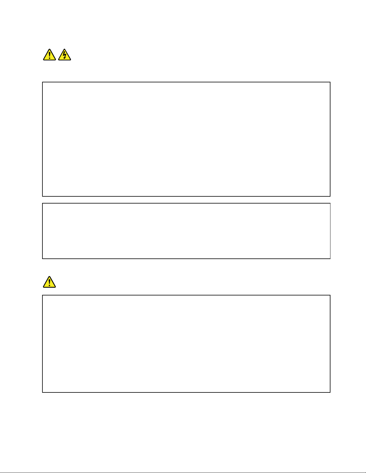
Statement1
DANGER
Electricalcurrentfrompower,telephone,andcommunicationcablesishazardous.
Toavoidashockhazard:
•Donotconnectordisconnectanycablesorperforminstallation,maintenance,orreconfigurationofthis
productduringanelectricalstorm.
•Connectallpowercordstoaproperlywiredandgroundedelectricaloutlet.
•Ensurethatallpowercordconnectorsaresecurelyandcompletelypluggedintoreceptacles.
•Connecttoproperlywiredoutletsanyequipmentthatwillbeattachedtothisproduct.
•Whenpossible,useonehandonlytoconnectordisconnectsignalcables.
•Neverturnonanyequipmentwhenthereisevidenceoffire,water,orstructuraldamage.
•Disconnecttheattachedpowercords,telecommunicationssystems,networks,andmodemsbeforeyou
openthedevicecovers,unlessinstructedotherwiseintheinstallationandconfigurationprocedures.
•Connectanddisconnectcablesasdescribedinthefollowingtablewheninstalling,moving,oropening
coversonthisproductorattacheddevices.
Toconnect:Todisconnect:
1.TurneverythingOFF.
2.First,attachallcablestodevices.
3.Attachsignalcablestoconnectors.
4.Attachpowercordstooutlets.
5.TurndevicesON.
1.TurneverythingOFF.
2.First,removepowercordsfromoutlets.
3.Removesignalcablesfromconnectors.
4.Removeallcablesfromdevices.
Statement2
DANGER
Dangerofexplosionifbatteryisincorrectlyreplaced.
Whenreplacingthelithiumcoincellbattery,useonlythesameoranequivalenttypethatis
recommendedbythemanufacturer .Thebatterycontainslithiumandcanexplodeifnotproperly
used,handled,ordisposedof.
Donot:
•Throworimmerseintowater
•Heattomorethan100°C(212°F)
•Repairordisassemble
Disposeofthebatteryasrequiredbylocalordinancesorregulations.
©CopyrightLenovo2014
v
Page 8
Statement3
CAUTION:
Whenlaserproducts(suchasCD-ROMs,DVDdrives,fiberopticdevices,ortransmitters)are
installed,notethefollowing:
•Donotremovethecovers.Removingthecoversofthelaserproductcouldresultinexposureto
hazardouslaserradiation.Therearenoserviceablepartsinsidethedevice.
•Useofcontrolsoradjustmentsorperformanceofproceduresotherthanthosespecifiedherein
mightresultinhazardousradiationexposure.
DANGER
SomelaserproductscontainanembeddedClass3AorClass3Blaserdiode.Notethefollowing:
Laserradiationwhenopen.Donotstareintothebeam,donotviewdirectlywithoptical
instruments,andavoiddirectexposuretothebeam.
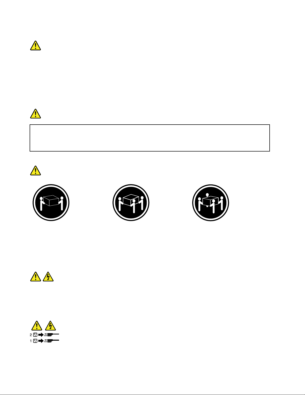
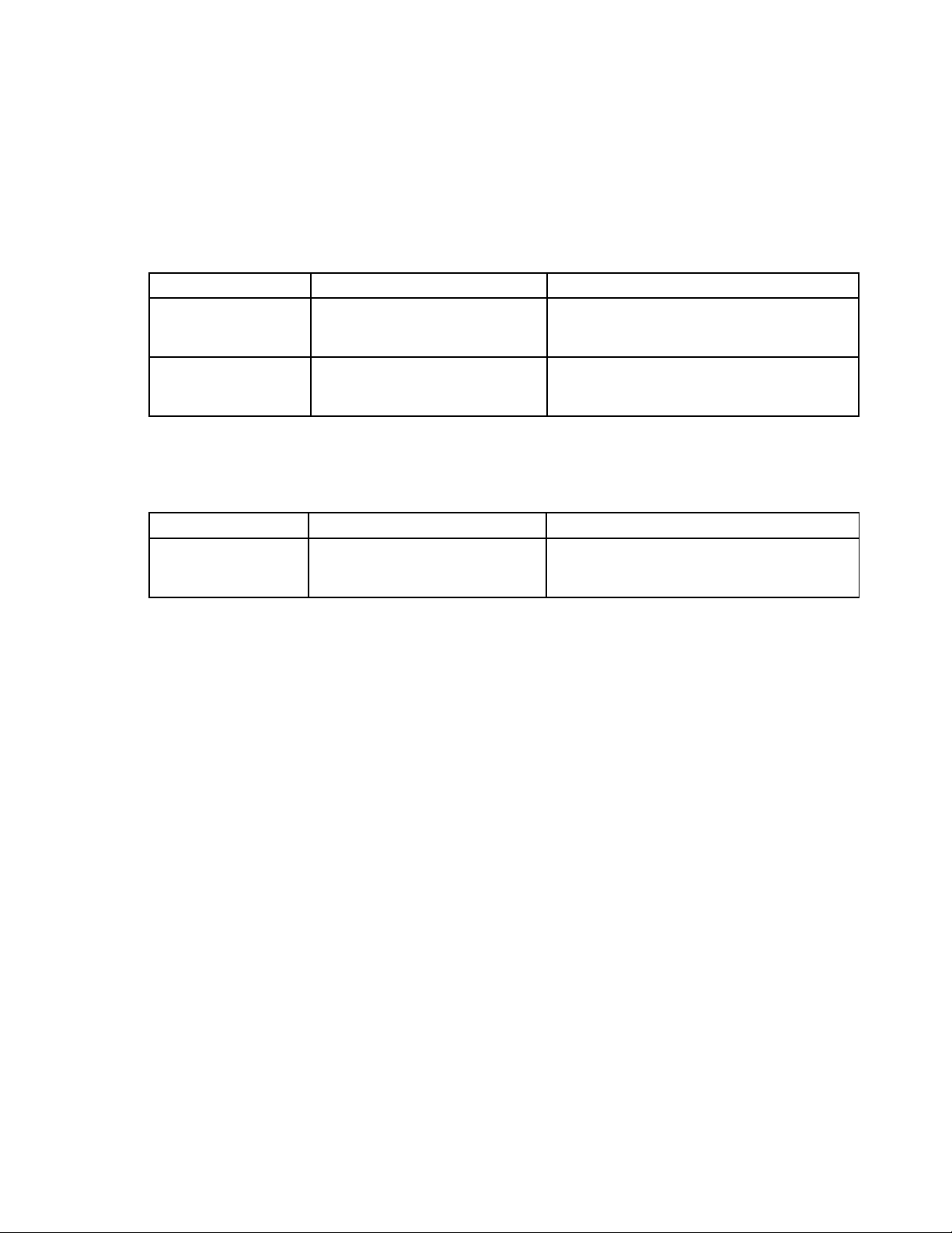
Statement4
≥18kg(39.7lb)≥32kg(70.5lb)≥55kg(121.2lb)
<32kg(70.5lb)<55kg(121.2lb)<100kg(220.5lb)
CAUTION:
Usesafepracticeswhenlifting.
Statement5
CAUTION:
Thepowercontrolbuttononthedeviceandthepowerswitchonthepowersupplydonotturnoff
theelectricalcurrentsuppliedtothedevice.Thedevicealsomighthavemorethanonepower
cord.Toremoveallelectricalcurrentfromthedevice,ensurethatallpowercordsaredisconnected
fromthepowersource.
viThinkServerRD550UserGuideandHardwareMaintenanceManual
Page 9
Statement6
CAUTION:
Ifyouinstallastrain-reliefbracketoptionovertheendofthepowercordthatisconnectedtothe
device,youmustconnecttheotherendofthepowercordtoapowersourcethatiseasilyaccessible
incaseitneedstobedisconnected.
Statement7
CAUTION:
Ifthedevicehasdoors,ensurethatyouremoveorsecurethedoorsbeforemovingorliftingthe
devicetoprotectagainstpersonalinjury.Thedoorswillnotsupporttheweightofthedevice.
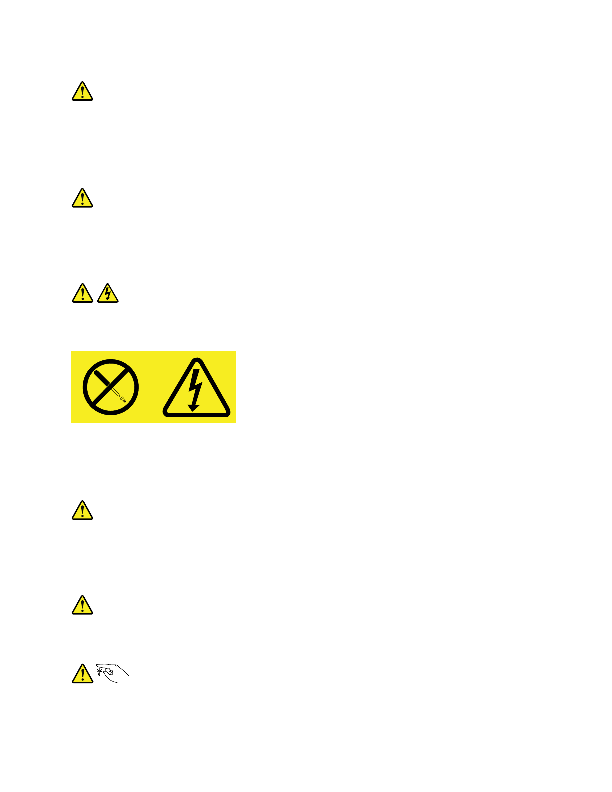
Statement8
CAUTION:
Neverremovethecoveronapowersupplyoranypartthathasthefollowinglabelattached.
Hazardousvoltage,current,andenergylevelsarepresentinsideanycomponentthathasthislabel
attached.Therearenoserviceablepartsinsidethesecomponents.Ifyoususpectaproblemwith
oneoftheseparts,contactaservicetechnician.
Statement9
CAUTION:
Disconnectthehot-swapfancablesbeforeremovingthefanfromthedevicetoprotectagainst
personalinjury.
Statement10
CAUTION:
Thefollowinglabelindicatesasharp-edgehazard.
©CopyrightLenovo2014
vii
Page 10
Statement11
CAUTION:
Thefollowinglabelindicatesapotentialheathazard.
Statement12
DANGER
Overloadingabranchcircuitisapotentialfirehazardandashockhazardundercertainconditions.To
avoidthesehazards,ensurethatyoursystemelectricalrequirementsdonotexceedbranchcurrentratings
attheinstallationsite.
Statement13
CAUTION:
Ensurethattherackissecuredproperlytoavoidtippingwhentheserverunitisextendedontherails.
Statement14
CAUTION:
SomeaccessoryoroptionboardoutputsexceedClass2orlimitedpowersourcelimits.Y ou
mustinstalltheappropriateinterconnectingcablinginaccordancewithyourlocalelectricalcode
requirements.
Statement15
CAUTION:
Thepower-controlbuttononthedevicemayputthedeviceinstandbymodeinsteadofturningoff
thedevice.Inaddition,thedevicemighthavemultipleconnectionstodcpower.T oremoveall
electricalcurrentfromthedevice,ensurethatallconnectionstodcpoweraredisconnectedat
thedcpowerinputterminals.
viiiThinkServerRD550UserGuideandHardwareMaintenanceManual
Page 11
Statement16
CAUTION:
Toreducetheriskofelectricshockorenergyhazards:
•Thisequipmentmustbeinstalledbytrainedservicepersonnelinarestricted-accesslocation,as
definedbyyourlocalelectricalcodeandthelatesteditionofIEC60950.
•Connecttheequipmenttoareliablyearthedsafetyextralowvoltage(SELV)source.AnSELV
sourceisasecondarycircuitthatisdesignedsothatnormalandsinglefaultconditionsdonot
causethevoltagestoexceedasafelevel(60Vdirectcurrent).
•Thebranchcircuitovercurrentprotectionmustberatedinaccordancewithlocalelectricalcode
requirements.
•Use1.3mm
2
or16AmericanWireGauge(AWG)copperconductoronly,notexceeding3meters
inlength.
•Torquethewiring-terminalscrewsto1.4newton-metersor12inch-pounds.
•Provideareadilyavailable,approvedandrateddisconnectdeviceinthefieldwiring.
Statement17
CAUTION:
ThisproductcontainsaClass1Mlaser.Donotviewdirectlywithopticalinstruments.
Statement18
CAUTION:
Donotplaceanyobjectontopofrack-mountedproducts.
Statement19
CAUTION:
Hazardousmovingparts.Keepfingersandotherbodypartsaway.
©CopyrightLenovo2014
ix
Page 12

Statement20
CAUTION:
Alithiumionbatteryisprovided.Toavoidpossibleexplosion,donotburnthebattery.Replacethe
batteryonlywiththeLenovo-approvedpart.Recycleordiscardthebatteryasinstructedbylocal
regulations.
Productsthatarenotassessed
Typicalproductsthatarenotassessedincludebutnotlimitedtothefollowing:
•ServerandIT-rackcomponents(forexample,uninterruptiblepowersuppliesandcurrentdistribution
systems)
•DevicesinITrooms(forexample,bulkstorageunitsandnetworkproducts)
•Industriallow-voltageswitchgear
Safetyinspectionguide
Thepurposeofthisinspectionguideistoassistyouinidentifyingpotentiallyunsafeconditions.Aseach
machinewasdesignedandbuilt,requiredsafetyitemswereinstalledtoprotectusersandservicetechnicians
frominjury.Thisguideaddressesonlythoseitems.Youshouldusegoodjudgmenttoidentifypotentialsafety
hazardsduetoattachmentofnon-ThinkServerfeaturesoroptionsnotcoveredbythisinspectionguide.
Ifanyunsafeconditionsarepresent,youmustdeterminehowserioustheapparenthazardcouldbeand
whetheryoucancontinuewithoutfirstcorrectingtheproblem.
Considertheseconditionsandthesafetyhazardstheypresent:
•Electricalhazards,especiallyprimarypower(primaryvoltageontheframecancauseseriousorfatal
electricalshock)
•Explosivehazards,suchasadamagedCathodeRayTube(CRT)monitororabulgingcapacitor
•Mechanicalhazards,suchaslooseormissinghardware
Todeterminewhetherthereareanypotentiallyunsafeconditions,usethefollowingchecklistatthebeginning
ofeveryservicetask.Beginthecheckswiththepoweroff,andthepowercordsdisconnected.
Checklist:
1.Checkexteriorcoversfordamage(loose,broken,orsharpedges).
2.Powerofftheserver.Disconnectthepowercords.
3.Checkthepowercordfor:
a.Athird-wiregroundconnectoringoodcondition.Useametertomeasurethird-wireground
continuityfor0.1ohmorlessbetweentheexternalgroundpinandtheframeground.
b.Thepowercordshouldbetheauthorizedtypespecifiedforyourserver.Goto:
http://www.lenovo.com/serviceparts-lookup.
c.Insulationmustnotbefrayedorworn.
4.Checkforcrackedorbulgingbatteries.
5.Removethecover.
6.Checkforanyobviousnon-ThinkServeralterations.Usegoodjudgmentastothesafetyofany
non-ThinkServeralterations.
xThinkServerRD550UserGuideandHardwareMaintenanceManual
Page 13

7.Checkinsidetheunitforanyobviousunsafeconditions,suchasmetalfilings,contamination,wateror
otherliquids,orsignsoffireorsmokedamage.
8.Checkforworn,frayed,orpinchedcables.
9.Checkthatthepower-supplycoverfasteners(screwsorrivets)havenotbeenremovedortamperedwith.
Groundingrequirements
Electricalgroundingoftheserverisrequiredforoperatorsafetyandcorrectsystemfunction.Proper
groundingoftheelectricaloutletcanbeverifiedbyacertifiedelectrician.
©CopyrightLenovo2014
xi
Page 14

xiiThinkServerRD550UserGuideandHardwareMaintenanceManual
Page 15

Chapter1.Generalinformation
Thischapterprovidessomegeneralinformationaboutyourproduct.
Thischaptercontainsthefollowingitems:
•“Introduction”onpage1
•“Serverdocumentation”onpage2
Introduction
ThisdocumentforyourLenovo
specifications,componentlocations,configurationinstructions,hardwarereplacementprocedures,and
basictroubleshootinganddiagnostics.
YourservercomeswithadocumentationDVDthatcontainsvariousserverdocumentstohelpyouuseand
maintaintheserver.Meanwhile,yourservercomeswiththeLenovoThinkServerDeploymentManager
programthatprovidesaconvenientsolutionforconfiguringtheserverandinstallinganoperatingsystem.
TheLenovoLimitedWarranty(LLW)containsthewarrantytermsthatapplytotheproductyoupurchasedfrom
Lenovo.ReadtheLLWonthedocumentationDVDthatcomeswithyourserver.Aprintablegenericversion
ofthelatestLLWalsoisavailableinmorethan30languagesathttp://www.lenovo.com/warranty/llw_01.If
youcannotobtaintheLLWthroughthedocumentationDVDorLenovoWebsite,contactyourlocalLenovo
officeorresellertoobtainaprintedversionoftheLLW,freeofcharge.
®
ThinkServer
®
productcontainsinformationabouttheserverfeatures,
Forwarrantyservice,consulttheworldwideLenovoSupporttelephonelist.Telephonenumbersaresubject
tochangewithoutnotice.Themostup-to-datetelephonelistforLenovoSupportisalwaysavailableonthe
Websiteathttp://www.lenovo.com/support/phone.Ifthetelephonenumberforyourcountryorregionisnot
listed,contactyourLenovoresellerorLenovomarketingrepresentative.
Toobtainthemostup-to-dateinformationabouttheserver,goto:
http://www.lenovo.com/thinkserver
LenovomaintainspagesontheWorldWideWeb,whereyoucangetthelatesttechnicalinformationand
downloaddocumentationordevicedriversandupdates.T oaccesstheLenovoSupportWebsite,goto:
http://www.lenovo.com/support
©CopyrightLenovo2014
1
Page 16

Recordinformationaboutyourserverinthefollowingtable.Youwillneedtheinformationifyoueverneed
tohaveyourserverserviced.
Forwheretofindtheproductinformationlabelonthechassis,see“Machinetype,model,andserialnumber
label”onpage16
.
Productname
Machinetypeandmodel(MT-M)
Serialnumber(S/N)
Dateofpurchase
______________________________________________
______________________________________________
______________________________________________
______________________________________________
YoucanregisteryourserverwithLenovobyfollowingtheinstructionsat:
http://www.lenovo.com/register
Whenyouregisteryourserver,informationisenteredintoadatabase,whichenablesLenovotocontact
youincaseofarecallorothersevereproblem.AfteryouregisteryourserverwithLenovo,youwillreceive
quickerservicewhenyoucallLenovoforhelp.Inaddition,somelocationsofferextendedprivilegesand
servicestoregisteredusers.
Serverdocumentation
Thistopicprovidesgeneraldescriptionsofthevariousdocumentationforyourserverandinstructionson
howtoobtainallthedocumentation.
Printeddocuments
Thefollowingdocumentsareprintedoutandcontainedinyourserverpackage.
•ReadMeFirst
Thisisamultilingualdocumentyoushouldreadfirst.Thisdocumentguidesyoutoreadthecomplete
warranty,support,andsafetyinformationonthedocumentationDVDthatcomeswithyourserverbefore
usingtheproduct.Thisdocumentalsoprovidesinformationabouthowtofindthemostup-to-date
informationontheLenovoSupportWebsite.
•RackInstallationInstructions
Thisdocumentprovidesinstructionsonhowtoinstallyourserverintoastandardrackcabinetbyusing
therailkitshippedwiththeserver.
Note:AprintedEnglishversionofthisdocumentisincludedinyourserverpackage.PDFversionsof
otherlanguagesareprovidedonthedocumentationDVDthatcomeswiththeserver.
2ThinkServerRD550UserGuideandHardwareMaintenanceManual
Page 17

DocumentationDVD
ThedocumentationDVD,whichcomeswithyourserver,containsvariousdocumentsforyourserverin
PortableDocumentFormat(PDF)andHyperTextMarkupLanguage(HTML).ThedocumentationDVDisnot
bootable.ToviewthedocumentsontheDVD,youwillneedacomputerwithaWebbrowserandtheAdobe
Readerprogram,whichisavailablefordownloadat:
http://www.adobe.com
TostartthedocumentationDVD,inserttheDVDintotheopticaldrive.TheDVDisAutoPlayenabledand
startsautomaticallyinmostMicrosoft
®
Linux
operatingsystem,openthelaunch.htmfilelocatedintherootdirectoryoftheDVD.
®
Windows
®
environments.IftheDVDfailstostartorifyouareusinga
Note:LenovomaintainspagesontheWorldWideWeb,whereyoucangetthelatesttechnicalinformation
anddownloaddocumentationordevicedriversandupdates.Someinformationinthedocumentsonthe
documentationDVDmightchangewithoutnoticeafterthefirstreleaseoftheDVD.Y oucanalwaysobtainall
themostup-to-datedocumentationforyourserverfromtheLenovoWebsiteat:
http://www.lenovo.com/UserManuals
ThefollowingdocumentsareonthedocumentationDVDthatcomeswithyourserver:
•Safety,Warranty,andSupportInformation
Thisisamultilingualdocumentthatincludesallthesafetystatementsforyourproductinmorethan30
languages.Besuretoreadandunderstandallthesafetystatementsbeforeusingtheproduct.This
documentalsoincludestheLenovowarrantystatement,CustomerReplaceableUnits(CRUs)information,
andinformationabouthowtocontacttheLenovoCustomerSupportCenter.
•LenovoLicenseAgreement
ThisdocumentincludesthetermsandconditionsoftheLenovoLicenseAgreement.
•UserGuideandHardwareMaintenanceManual
Thisdocumentprovidesdetailedinformationtohelpyougetfamiliarwithyourserverandhelpyouuse,
configure,andmaintainyourserver.
•RackInstallationInstructions
Thisdocumentprovidesinstructionsonhowtoinstallyourserverintoastandardrackcabinetbyusing
therailkitshippedwiththeserver.
•ThinkServerSystemManagerUserGuide
Thisdocumentprovidesinformationaboutserverremotemanagement.ThisdocumentisinEnglishonly.
YoumightfindthisdocumentonthedocumentationDVDthatcomeswithyourserver.Ifnot,downloadit
fromtheLenovoWebsiteat:
http://www.lenovo.com/UserManuals
Note:Toobtainadvancedremotemanagementfunctions,installaThinkServerSystemManagerPremium
(TSMPremium)moduleontheTSMPremiumconnectoronthesystemboard.See“Installingorremoving
theThinkServerSystemManagerPremiummodule”onpage71
.
•MegaRAIDSASSoftwareUserGuide
ThisdocumentprovidesinformationaboutRedundantArrayofIndependentDisks(RAID)andhowto
usetheutilityprogramstoconfigure,monitor,andmaintainyourserverRAIDandrelateddevices.This
documentisinEnglishonly.
•Otherdocuments
YoumightfindotherdocumentsfortheHostBusAdapter(HBA),Ethernetcard,orotheroptionalparts
onthedocumentationDVD.
Chapter1.Generalinformation3
Page 18

4ThinkServerRD550UserGuideandHardwareMaintenanceManual
Page 19

Chapter2.Serversetuproadmap
Thischapterprovidesageneralroadmaptoguideyouthroughsettingupyourserver.
Theserversetupprocedurevariesdependingontheconfigurationoftheserverwhenitwasdelivered.In
somecases,theserverisfullyconfiguredandyoujustneedtoconnecttheservertothenetworkandan
acpowersource,andthenyoucanturnontheserver.Inothercases,theserverneedstohavehardware
featuresinstalled,requireshardwareandfirmwareconfiguration,andrequiresanoperatingsystemto
beinstalled.
Thegeneralprocedureforsettingupyourserveris:
1.Unpacktheserverpackage.See“Serverpackage”onpage7.
2.Installanyrequiredhardwareorserveroption.SeetherelatedtopicsinChapter6“Replacinghardware”
onpage59.
3.Ifyouhavearailkit,installyourserverintoastandardrackcabinet.SeetheRackInstallationInstructions
thatcomeswiththeserver.
4.ConnecttheEthernetcableandpowercordstotheserver.See“Rearviewoftheserver”onpage
tolocatetheconnectors.
21
5.Turnontheservertoverifyoperation.See“Turningontheserver”onpage45.
6.ReviewtheUnifiedExtensibleFirmwareInterface(UEFI)settingsandcustomizeasneeded.See“Using
theSetupUtilityprogram”onpage47
7.ConfigureRAIDandinstalltheoperatingsystemandbasicdrivers.See“LenovoThinkServer
DeploymentManager”onpage14
8.Installanyadditionaldriversneededforaddedfeatures.Refertotheinstructionsthatcomewiththe
hardwareoption.
9.ConfigureEthernetsettingsintheoperatingsystembyreferringtotheoperatingsystemhelp.This
stepisnotrequirediftheoperatingsystemwasinstalledusingtheLenovoThinkServerDeployment
Managerprogram.
10.Checkforfirmwareanddriverupdates.See“Updatingthefirmware”onpage57.
11.Installotherapplications.Refertothedocumentationthatcomeswiththeapplicationsthatyouwantto
install.
.
and“ConfiguringRAID”onpage54.
©CopyrightLenovo2014
5
Page 20

6ThinkServerRD550UserGuideandHardwareMaintenanceManual
Page 21

Chapter3.Productoverview
Thischapterprovidesinformationabouttheserverpackage,features,specifications,softwareprograms,
andcomponentlocations.
Thischaptercontainsthefollowingitems:
•“Serverpackage”onpage7
•“Features”onpage7
•“Specifications”onpage12
•“Software”onpage13
•“Locations”onpage16
Serverpackage
Theserverpackageincludesthefollowingitems:
•Server
•Railkit(availableonsomemodels)
•Cablemanagementarmorcablemanagementbar(availableonsomemodels)
•Slimopticaldrive(availableonsomemodels)
•Materialbox,includingitemssuchaspowercords,printeddocumentation,andadocumentationDVD
Features
Thistopicprovidesgeneralinformationabouttheserverfeaturesforvariousmodels.Dependingonyour
specificmodel,somefeaturesmightvaryorunavailable.Forinformationaboutyourspecificmodel,usethe
SetupUtilityprogram.See“ViewinginformationintheSetupUtilityprogram”onpage47
totheProductSpecificationsReferencedocumentforThinkServerproductsat:
http://www.lenovo.com/psref/
Microprocessor
OneortwoIntel
Memory
Yourserverhas24memoryslots.Formoreinformation,see“Memorymoduleinstallationrules”onpage66.
®
®
Xeon
microprocessors(internalcachesizevariesbymodel)
.Youalsocanrefer
©CopyrightLenovo2014
7
Page 22

Powersupply
•Oneortwo550-watthot-swapredundantpowersupplies(Universalinputandcompliantwith80PLUS
Platinum)
•Oneortwo750-watthot-swapredundantpowersupplies(Universalinputandcompliantwith80PLUS
Platinum)
•Oneortwo750-watthot-swapredundantpowersupplies(Universalinputandcompliantwith80PLUS
Titanium)
•Oneortwo1100-watthot-swapredundantpowersupplies(Universalinputandcompliantwith80
PLUSPlatinum)
Notes:
•For550-watt,750-watt,or1100-wattPlatinumpowersupply:90-264Vac
•For750-wattTitaniumpowersupply:180-264Vac
Systemfans
Yourserversupportsuptoeighthot-swapsystemfanswithredundancy.Thisdesignhelpsyoutoavoid
significantcoolingproblemswhenasystemfanfails.Youcanreplaceahot-swapsystemfanwithout
turningofftheserver.
8ThinkServerRD550UserGuideandHardwareMaintenanceManual
Page 23
Internaldrives
Internaldrivesaredevicesthatyourserverusestoreadandstoredata.Theinternaldrivessupported
byyourservervarybymodel.
•Internalstoragedrive
–Inthefront:
Yourserversupportsoneofthefollowingstoragedriveconfigurations:
DrivebaysizeDrivebayquantityDrivetype
Hot-swap,SA TAorSAS
3.5-inch4
Harddiskdriveor2.5-inchsolid-statedrive
Hot-swap,SA TAorSAS
2.5-inch12
Harddiskdriveorsolid-statedrive
Note:Youcaninstalla2.5-inchsolid-statedriveintoa3.5-inch-drivebay.Formoreinformation,see
“Installinga2.5-inchsolid-statedriveintoa3.5-inchhard-disk-drivebay”onpage126.
–Intherear:(forservermodelswiththefour3.5-inchdrivesonly)
DrivebaysizeDrivebayquantityDrivetype
Hot-swap,SATA
2.5-inch2
Harddiskdriveorsolid-statedrive
Notes:
–SATAistheacronymforSerialAdvancedTechnologyAttachment.
–SASstandsforSerialAttachedSCSI(SCSIistheacronymforSmallComputerSystemInterface).
–YoucaninstallSATAharddiskdrives,SASharddiskdrives,andsolid-statedrivesintothesameserver.
Thefollowingservermodelsalsoareavailable:
–Servermodelswithoutharddiskdrivesorsolid-statedrives
–Servermodelswithoutharddiskdrives,solid-statedrives,backplanes,AnyRAIDadapters,andrelated
cables
•Opticaldrive
–OneslimSATAopticaldriveinsomemodels
Forthelocationinformationabouttheinternaldrivesordrivebays,see“Servercomponents”onpage25
Expansionslots
•Tworisercardassemblyslotsonthesystemboard
•OneortwoPCIExpress(PCIe)cardslotsontherisercard
•OneortwoAnyFabricslotsattherearoftheserver
Fordetailedinformation,see“Rearviewoftheserver”onpage21
.
.
Chapter3.Productoverview9
Page 24

Input/Output(I/O)features
•Ontherearpanel:
–OneDisplayPortconnector
–OneRJ-45Ethernetconnectorforsystemmanagement
–Oneserialconnector
–TwoUSB3.0connectors
•Onthefrontpanel(availableonsomemodels):
–OneDisplayPortconnector
–TwoUSB2.0connectors
Notes:
•IfyouconnecttwoDisplayPortconnectorstoyourserver,onlytheDisplayPortconnectoronthefront
panelwillbeenabled.
•Ifyouuseavideographicsarray(VGA)monitor,itisrecommendedthatyoupurchaseacompatible
DisplayPorttoVGAdonglefromLenovo.
Forthelocationinformationabouttheconnectors,refertotherelatedtopicsin“Locations”onpage16
.
Videosubsystem
AnintegratedgraphicscontrollerintheThinkServerSystemManagerPremium(TSMPremium)module,
whichalsoisknownastheBaseboardManagementController(BMC)chip,onthesystemboardtosupport
DisplayPortconnectorsforconnectingvideodevices
•Integratedgraphicscontroller:On-boardASPEEDAST2400
•16MBofvideomemorycache
Ethernetconnectivity
ThereisoneRJ-45Ethernetconnectorontherearpanelwith10megabitspersecond(Mbps),100Mbps,or
1000Mbpsnetworkconnectivity.TheEthernetconnectorisforsystemmanagement.
YoucaninstallanEthernetcardoranAnyFabricadaptertoenablemoreEthernetconnectors.However,you
mustinstalladevicedrivertoenabletheoperatingsystemtorecognizetheEthernetconnectors.Thedevice
driversareavailablefordownloadat:
http://www.lenovo.com/drivers
Formoreinformation,see“Rearviewoftheserver”onpage21.
Reliability,availability,andserviceability
Reliability,availability,andserviceability(hereinafterreferredtoasRAS)arethreeimportantserverdesign
features.TheRASfeatureshelpyoutoensuretheintegrityofthedatastoredontheserver,theavailabilityof
theserverwhenyouneedit,andtheeasewithwhichyoucandiagnoseandcorrectproblems.
YourserverhasthefollowingRASfeatures:
10ThinkServerRD550UserGuideandHardwareMaintenanceManual
Page 25

•Securityfeatures
–Administratorpasswordanduserpasswordtohelpprotectunauthorizedaccesstotheserver(see
“Usingpasswords”onpage50
)
–ThinkServerT rustedPlatformModule(TPM),whichisasecuritychip,tohelpenhanceserversecurity
Note:TheTPMisonlyavailableinsomemodels.
–Remotemonitoringorcontrolbyanadministratortoprovideprotectionorhelp
–Hot-swapredundantpowersuppliestohelpavoidsignificantinterruptiontotheoperationofthe
systemwhenapowersupplyfails
–Anintrusionswitchthatinformsyouthattheservercoverisnotproperlyinstalledorclosedbycreating
aneventinthesystemeventlog(SEL)
•Basicsystemmanagementfeatures
–Abilitytostorethepower-onself-test(POST)hardwaretestresults
–BIOSSetupUtilityprogram
TheBIOSSetupUtilityprogramhelpsyouviewtheserverinformationandconfiguretheserverinthe
pre-operatingsystemenvironment.See“UsingtheSetupUtilityprogram”onpage47.
–TSM(alsoknownasBMC)andIntelligentPlatformManagementInterface(IPMI)2.0
ThesystemboardplatformmanagementsubsystemisbasedontheintegratedTSMfeatures.The
TSMisamanagementchipthatisintegratedonthesystemboardofyourserver.WiththeTSM,no
matterwhatconditiontheserveroperatingsystemisinandnomatteriftheserverisonoroff,aslong
astheserverisconnectedtonetworkandanacpowersource,theinteractionwiththeTSM-controlled
serverscanbeachievedthroughsystemnetwork.Theusercanobtaintheserverhardwarehealth
informationandsystemeventlog(SEL),andisabletoconducttheoperationsincludingturningonor
offtheserver,restartingtheserver,andsoon.Thispartofservermanagementisindependentofthe
operatingsystemandiscalledout-of-bandmanagement.
ThesystemboardplatformmanagementsubsystemconsistsoftheintegratedTSM,communication
buses,sensors,theBIOS,andservermanagementfirmware.Itisresponsibleforerrorreporting,
systempowercontrol,thermalmonitoring,systemfancontrol,andothermanagementfeatures.The
TSMprovidessystemmanagementandmonitoringfeaturesbasedontheIPMI2.0specification.IPMI
helpslowertheoverallcostsofservermanagement.Y oucanfindmoreinformationaboutIPMI2.0
fromtheWebsiteofIntel.TheTSMalsosupportssomenon-IPMIfeatures,suchastheDynamicHost
ConfigurationProtocol(DHCP)andthePlatformEnvironmentControlInterface(PECI),toprovide
moresystemmanagementfunctions.
Youcanfindthedefaultusername,password,andotherinformationfortheTSMintheThinkServer
SystemManagerUserGuide,whichisavailablefordownloadat:
http://www.lenovo.com/UserManuals
–Hot-swapfeature
Yourserversupportshot-swapstoragedrives(includingharddiskdrivesandsolid-statedrives),
hot-swapsystemfans,andhot-swapredundantpowersupplies.Withthehot-swapfeature,youcan
install,remove,orreplaceahot-swapdevicewithoutturningofftheserver.
–PrebootExecutionEnvironment(PXE)
TheIntelPXEtechnologyenablesyoutobootyourcomputers,loadanoperatingsystem,ordeploy
executableimagesfromaremoteserverbyusinganetworkinterface.Theoperationcanbedone
independentlyoflocaldatastoragedevices(suchasharddiskdrives)oroperatingsystems.
–RedundantArrayofIndependentDisks(RAID)
YourserversupportsonboardSATAsoftwareRAID.IfarequiredRAIDcardisinstalled,yourserver
alsosupportsadvancedSATA/SAShardwareRAIDconfigurations.Fordetailedinformation,see
“ConfiguringRAID”onpage54.
Chapter3.Productoverview11
Page 26

–Statuslight-emittingdiodes(LEDs)anddiagnosticLEDs
FormoreinformationabouttheLEDsforyourserver,refertotherelatedtopicsin“Locations”on
page16.
–Softwareprograms
Formoreinformationaboutthesoftwareprograms,see“Software”onpage13.
–WakeonLAN
WakeonLANisanEthernetcomputernetworkingstandardthatallowsacomputeroraservertobe
turnedonorwokenupbyanetworkmessage.Themessageisusuallysentbyaprogramrunningon
anothercomputeronthesamelocalareanetwork.
•Advancedsystemmanagementfeatures
TheadvancedsystemmanagementfeaturesareonlyavailablewhentheTSMdetectsthepresenceofa
TSMPremiummodule.TheTSMPremiummoduleisaremotemanagementmodule.Youcanpurchasea
TSMPremiummodulefromLenovoandinstallitonthesystemboardtoactivatetheadvancedsystem
managementfeatures.
Formoreinformationaboutadvancedsystemmanagement,refertotheThinkServerSystemManager
UserGuide,whichisavailablefordownloadat:
http://www.lenovo.com/UserManuals
Specifications
Thistopicliststhephysicalspecificationsforyourserver.
Dimensions
Widthwithoutrackhandles:447mm(17.59inches)
Widthwithrackhandles:482mm(18.98inches)
Depthwithoutrackhandlesandpowersupplyhandles:779.8mm(30.70inches)
Depthwithrackhandlesandpowersupplyhandles:802.8mm(31.61inches)
Height:43mm(1.69inches)
Weight
Theproductweightvariesdependingondifferentsystemconfigurations.
Rangeofproductweightwithoutpackage:13.5kg(29.76lb)to21kg(46.29lb)
Rangeofproductweightwithpackage:19.8kg(43.65lb)to27.3kg(60.19lb)
Environment
YourservercomplieswithASHRAEclassA2specifications.Dependingonthehardwareconfiguration,some
servermodelscomplywithASHRAEclassA3andclassA4specifications.TocomplywithASHRAEclass
A3andclassA4specifications,yourservermodelsneedtomeetthefollowinghardwareconfiguration
requirementsatthesametime:
•Lenovo-qualifiedCPUexceptthefollowingtypes:
–135-wattCPU(4-core,6-core,or8-core)
–145-wattCPU(14-coreor18-core)
•Twopowersupplies(exceptthe1100-wattpowersupplies)installedforredundancy
ThefollowingtableprovidesdetailedinformationabouttheASHRAEclassspecifications.
12ThinkServerRD550UserGuideandHardwareMaintenanceManual
Page 27
Table1.ASHRAEclassspecifications
Airtemperature
(operating)
Airtemperature
(storage)
Humidity(operating)
Humidity(storage)
Altitude
ASHRAEclassA2ASHRAEclassA3ASHRAEclassA4
10°Cto35°C(50°Fto95°F)5°Cto40°C(41°Fto104°F)5°Cto45°C(41°Fto113°F)
-40°Cto60°C(-40°Fto
140°F)inoriginalshipping
package
8%to80%
(non-condensing)
8%to90%
(non-condensing)
0to3048m(0to10000ft)inanunpressurizedenvironment
Note:Whenthealtitudeexceeds900m(2953ft),thedefinedmaximumdry-bulb
temperatureforoperationbecomesadependentvariable.
A2:Thistemperaturevaluedecreasesby1°C(33.8°F)withevery300m(984ft)
ofaltitudeincrease.
A3:Thistemperaturevaluedecreasesby1°C(33.8°F)withevery175m(574ft)
ofaltitudeincrease.
A4:Thistemperaturevaluedecreasesby1°C(33.8°F)withevery125m(410ft)
ofaltitudeincrease.
-40°Cto60°C(-40°Fto
140°F)inoriginalshipping
package
8%to85%
(non-condensing)
8%to90%
(non-condensing)
-40°Cto60°C(-40°Fto
140°F)inoriginalshipping
package
8%to90%
(non-condensing)
8%to90%
(non-condensing)
Electricalinput
•Universalinput:
–Lowrange:
Minimum:100Vac
Maximum:127Vac
Inputfrequencyrange:50to60Hz
–Highrange:
Minimum:200Vac
Maximum:240Vac
Inputfrequencyrange:50to60Hz
Software
Thistopicprovidesinformationaboutthesoftwareprogramsthatyoucanusetosetup,use,andmaintain
theserver.
Todownloadthesoftwareprograms,gototheLenovoSupportWebsiteathttp://www.lenovo.com/support
andfollowtheinstructionsontheWebpage.
BIOSandTSMupdateutilities
TheBIOSandTSM(alsoknownasBMC)firmwarekeepsupdatingaftertheshipmentoftheserver.Lenovo
maintainspagesontheSupportWebsiteandprovidestheBIOSandTSMupdateutilitieswithinstructions
fordownloadtohelpyouupdatetheBIOSandTSMfirmwareifneeded.Formoreinformation,see“Updating
orrecoveringtheBIOS”onpage53
and“Updatingthefirmware”onpage57.
Chapter3.Productoverview13
Page 28

LenovoPartnerPackforMicrosoftSystemCenterOperations Management
TheLenovoPartnerPackforMicrosoftSystemCenterOperationsManagementprogramcanautomatically
detectthemanagedserversandprovidedetailedsysteminformationabouttheservers.Thesystem
informationincludestheinventoryandstatusofcomponentssuchasmicroprocessors,memorymodules,
fans,andtemperaturesensors.Theprogramalsoenablesyoutoperformmanagementtasks,suchas
restartingorturningoffyourserver,startingaremoteconsole,andaccessingtheTSMinterface.
Fordetailedinformationaboutusingtheprogram,refertothehelpsystemoftheprogram.
LenovoThinkServerDeploymentManager
TheLenovoThinkServerDeploymentManagerprogram(hereinafterreferredtoasDeploymentManager)
simplifiestheprocessofconfiguringRAID,configuringBIOSsettings,andupdatingthefirmware.The
programworksinconjunctionwithyourWindowsorLinuxoperatingsysteminstallationdisctoautomatethe
processofinstallingtheoperatingsystemandassociateddevicedrivers.Theprogramispartoftheserver
firmware.Thehelpsystemfortheprogramcanbeaccesseddirectlyfromtheprograminterface.
DeploymentManagerhasthefollowingfeatures:
•Easy-to-use,language-selectableinterface
•Integratedhelpsystem
•Automatichardwaredetection
•Selectablepartitionsizeandfilesystemtype
•Abilitytoinstalltheoperatingsystemanddevicedriversinanunattendedmodetosavetime
•AbilitytocreateareusableresponsefilethatcanbeusedwithsimilarlyconfiguredLenovoserversto
makefutureinstallationsevenfaster
•ContainsRAIDconfigurationutility
•Providesdevicedriversbasedontheservermodelanddetecteddevices
•SupportsBIOSsettingsconfiguration
•Supportsfirmwareandapplicationsupdate
TouseDeploymentManager,dothefollowing:
1.Launchtheprogramthroughoneofthefollowingmethods:
•Turnontheserver.PressF10assoonasyouseethelogoscreen.Then,waitforseveralseconds.
DeploymentManageropens.
•StarttheSetupUtilityprogram.SelectBootManager➙LaunchTDM.DeploymentManageropens.
2.Readandacceptthelicenseagreement.
3.Selectthelanguageinwhichyouwanttoviewtheprogram.Then,followtheinstructionsonthe
screentousetheprogram.
BeforeinstallingaWindowsoraLinuxoperatingsystemusingDeploymentManager,itisrecommended
thatyoudothefollowing:
1.Downloadthelatestdevicedriverbundlefileforyourserver.Tofindanddownloadthebundlefile,goto
http://www.lenovo.com/driversandfollowtheinstructionsontheWebpage.
2.LaunchDeploymentManagerandclickPlatformUpdateontheleftpane.
3.SelectApplicationandthenclickNext.
4.ClickBrowsetoselectthecorrespondingbundlefileandthenclickOK.Theversioninformationis
displayed.
14ThinkServerRD550UserGuideandHardwareMaintenanceManual
Page 29

5.ClickFlashtoapplythebundlefileandupdatethecurrentdevicedrivers.
Note:IfyouwanttoinstallaVMwarehypervisorusingDeploymentManager,thedevicedriverbundle
fileisnotneeded.
TodownloadthelatestDeploymentManager,gotohttp://www.lenovo.com/driversandfollowthe
instructionsontheWebpage.
LenovoThinkServerDiagnostics
TheLenovoThinkServerDiagnosticsprogramenablesyoutodiagnoseserverproblems,performsome
diagnostictests,andcollectsysteminformation.Examplesofthesysteminformationincludebasic
operating-systeminformation,hardwareinformation,SEL,RAIDlog,andsoon.Dependingonthemodel,
yourservermightcomewithoneofthefollowingdiagnosticprograms:
•LenovoThinkServerDiagnosticsLinuxEdition
•LenovoThinkServerDiagnosticsStandaloneEdition
•LenovoThinkServerDiagnosticsWindowsEdition
FordetailedinformationaboutusingtheLenovoThinkServerDiagnosticsprogram,refertothehelpsystem
fortheprogram.
LenovoThinkServerEnergyManager
TheLenovoThinkServerEnergyManagerisatoolfordatacenterpowermanagement.Itmonitorsthepower
andtemperatureatthedevicelevelandthegrouplevel.Bymonitoringandanalyzingpowerandtemperature
information,EnergyManagerhelpsyoutoincreasepowerefficiencyandimprovebusinesscontinuity.
ForinformationaboutusingEnergyManager,refertothehelpsystemoftheprogram.
LenovoThinkServerOperatingSystem-basedPlatformUpdateTool
TheLenovoThinkServerOperatingSystem-basedPlatformUpdateT oolisusedtoupdatethefirmwarein
theoperatingsystemforyourserver.
Fordetailedinformationaboutusingtheprogram,refertothehelpsystemoftheprogram.
LenovoThinkServerPowerPlanner
TheLenovoThinkServerPowerPlannerprogramprovidesinformationaboutdatamaintenance,power
consumption,electriccurrentcalculations,andsoon.Theprogramhelpsyouconvenientlymanageservers
anddevicestoincreasethedeploymentefficiencysignificantly.
FordetailedinformationaboutusingtheLenovoThinkServerPowerPlannerprogram,refertothehelp
systemoftheprogram.
LenovoThinkServerSystemManager
TheLenovoThinkServerSystemManager(TSM)isamanagementsolutionthatprovidescomprehensive
andsecuremanagementfeatures.Thesefeaturesenableyoutomanageyourserversremotelyusing
aone-to-oneorone-to-manymethod.
TheTSMprovidesaone-to-oneweb-basedconsole.Theweb-basedconsoleisdevelopedinHTML5and
structuredinthewaythatmakesplatformmanagementintuitiveandefficient.TheTSMalsoprovidesa
securecommand-lineinterfacetomanageyourserversusingaone-to-manymethodforimprovedefficiency
andfunctionality.
Chapter3.Productoverview15
Page 30
FordetailedinformationaboutusingtheLenovoThinkServerSystemManager,refertotheintegrated
MT-M XXXX- XXX
S/N XXXXXXX
helpscreensanduserguides.
LenovoThinkServerSystemManagerPremium
LenovoThinkServerSystemManagerPremiumprovidesyouasolutionthatenablesyoutoreceiveallthe
benefitsandfeaturesprovidedbyboththeLenovoThinkServerSystemManagerprogramandtheLenovo
ThinkServerEnergyManagerprogram.ItalsoenablesyoutocontroltheserverremotelyusingLenovovirtual
keyboard,video,andmouse.
FordetailedinformationaboutusingtheLenovoThinkServerSystemManagerPremiumfeaturesandtools,
refertotheintegratedhelpscreensanduserguides.
Locations
Thistopicprovidesinformationtohelpyoulocateyourservercomponents.
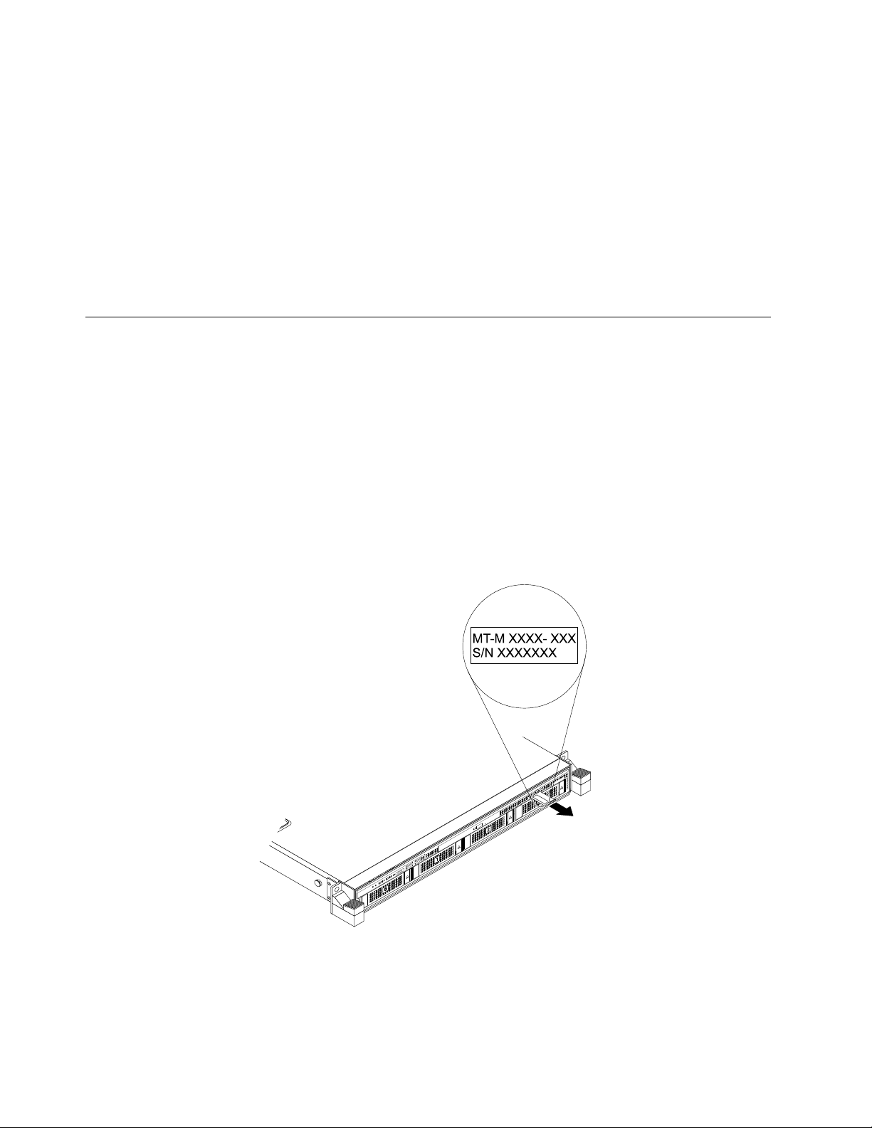
Machinetype,model,andserialnumberlabel
WhenyoucontactLenovoforhelp,themachinetype,model,andserialnumberinformationhelpssupport
technicianstoidentifyyourserverandprovidefasterservice.
Themachinetype,model,andserialnumberlabelisattachedonthepull-outinformationcard,whichisa
smallplastictabandcanbeslidoutofthefrontofthechassis.Thefollowingillustrationsaresamplesofthe
machinetype,model,andserialnumberlabelsonservermodelswithdifferentharddiskdriveconfigurations.
Note:Dependingonthemodel,yourservermightlookslightlydifferentfromtheillustrationsinthistopic.
Figure1.Labelonservermodelswith3.5-inch-drivebays
16ThinkServerRD550UserGuideandHardwareMaintenanceManual
Page 31

MT-M XXXX- XXX
S/N XXXXXXX
Figure2.Labelonservermodelswith2.5-inch-drivebays
Frontviewoftheserver
Thefrontviewoftheservervariesbymodel.Theillustrationsinthistopicshowtheserverfrontviews
basedonthesupportedinternaldrives:
•“Frontviewofservermodelswith3.5-inchdrives”onpage17
•“Frontviewofservermodelswith2.5-inchdrives”onpage18
Note:Dependingonthemodel,yourservermightlookslightlydifferentfromtheillustrationsinthistopic.
Frontviewofservermodelswith3.5-inchdrives
Figure3.Frontviewofservermodelswith3.5-inchdrives
1Frontpanel
3Pull-outinformationcard
53.5-inch-drivebays(0-3)6Rackhandle(left)
1Frontpanel
2Slimopticaldrive(availableonsomemodels)
4Rackhandle(right)
Fordetailedinformationaboutthecontrols,connectors,andstatusLEDsonthefrontpanel,see“Front
panel”onpage19.
Chapter3.Productoverview17
Page 32

2Slimopticaldrive(availableonsomemodels)
SomeservermodelscomewithaslimSATAopticaldrive.
3Pull-outinformationcard
Themachinetype,model,andserialnumberlabeloftheserverisattachedonthepull-outinformationcard.
See“Machinetype,model,andserialnumberlabel”onpage16.
4Rackhandle(right)
6Rackhandle(left)
Ifyourserverisinstalledinarackcabinet,youcanusetherackhandlestohelpyouslidetheserveroutof
therackcabinet.Youalsocanusetherackhandlesandscrewstosecuretheserverintherackcabinetso
thattheservercannotslideout,especiallyinvibration-proneareas.Formoreinformation,refertotheRack
InstallationInstructionsthatcomeswithyourserver.
53.5-inch-drivebays(0-3)
TheEMIintegrityandcoolingoftheserverareprotectedbyhavingalldrivebayscoveredoroccupied.
Thenumberoftheinstalledharddiskdrivesinyourservervariesbymodel.Thevacanthard-disk-drive
baysareoccupiedbydummyhard-disk-drivetrays.
Whenyouinstalldrives,followtheorderofthedrivebaynumbers.
Frontviewofservermodelswith2.5-inchdrives
Figure4.Frontviewofservermodelswith2.5-inchdrives
1Frontpanel
3Rackhandle(right)42.5-inch-drivebays(0-11)
5Rackhandle(left)
1Frontpanel
Fordetailedinformationaboutthecontrols,connectors,andstatusLEDsonthefrontpanel,see“Front
panel”onpage19
2Pull-outinformationcard
.
Themachinetype,model,andserialnumberlabeloftheserverisattachedonthepull-outinformationcard.
See“Machinetype,model,andserialnumberlabel”onpage16.
2Pull-outinformationcard
18ThinkServerRD550UserGuideandHardwareMaintenanceManual
Page 33

3Rackhandle(right)
5Rackhandle(left)
Ifyourserverisinstalledinarackcabinet,youcanusetherackhandlestoslidetheserveroutoftherack
cabinet;orusetherackhandlesandscrewstosecuretheserverintherackcabinetsothattheserver
cannotslideout,especiallyinvibration-proneareas.Formoreinformation,refertotheRackInstallation
Instructionsthatcomeswithyourserver.
42.5-inch-drivebays(0-11)
TheEMIintegrityandcoolingoftheserverareprotectedbyhavingalldrivebayscoveredoroccupied.
Thenumberoftheinstalleddrivesinyourservervariesbymodel.Thevacantdrivebaysareoccupied
bydummytrays.
Whenyouinstalldrives,followtheorderofthedrivebaynumbers.
Frontpanel
Thefollowingillustrationshowsthecontrols,connectors,andLEDsonthefrontpaneloftheserver.The
frontpanelvariesbymodel.
Figure5.Frontpanelforservermodelswith3.5-inch-drivebays
Figure6.Frontpanelforservermodelswith2.5-inch-drivebays
1NetworkstatusLED
3PowerbuttonwithpowerstatusLED
5DisplayPortconnector(availableonsome
models)
1NetworkstatusLED
2SystemhealthLED
4SystemIDbuttonwithIDLED
6USB2.0connectors(2)(availableonsomemodels)
ThenetworkstatusLEDonthefrontpanelhelpsyouidentifythenetworkconnectivityandactivity.
StatusColor
Blinking
Off
Green
None
TheAnyFabricnetworkisconnectedandactive.
TheserverisdisconnectedfromtheAnyFabricnetworkortheAnyFabric
networkisnotactive.
Description
Chapter3.Productoverview19
Page 34

2SystemhealthLED
ThesystemhealthLEDhelpsyoutodetermineifthereareanysystemerrors.
•Off:Theserverisoffortheserverisonandworkingcorrectly.
•Amber:Theserverhaspotentialsystemerrors.Checktheinformationinthefollowingtableforpotential
systemerrorsandcorrespondingsolutions.
•Blinking:Systeminitializationisongoing.
Potentialsystemerror(systemhealthLED:amber)Solution
Thetemperatureoftheserverreachedthenon-critical
temperaturethreshold.
Thevoltageoftheserverreachedthenon-criticalvoltage
threshold.
Afanisrunningatlowspeed.
Ahot-swapfanhasbeenremoved.1.Ensurethatthesystemfansareconnectedsecurely
Thepowersupplyhasacriticalerror.
Apowercordhasbeendisconnectedoraredundant
powersupplyhasbeenremoved.
Thesystemisoverheated.
ChecktheBMCforerrorsandcheckthesystemfans.
Replacethesystemboard.
Note:ThisactionmustbeperformedonlybyLenovo
servicepersonnel.SeeChapter8“Gettinginformation,
help,andservice”onpage157
Checkthesystemfans.
tothesystemboard.
2.Reinstalltheremovedfanorinstallanewfanto
replacetheremovedfan.
ChecktheBMCfordetailedinformation.
1.Ensurethatthepowersuppliesareinstalledsecurely.
2.Ensurethatthepowercordsareconnectedsecurely
tothepowersupplies.
3.Installanewpowersupplytoreplacetheremoved
one.
ChecktheBMCforerrorsandthencheckthesystem
fans.
.
3PowerbuttonwithpowerstatusLED
Youcanpressthepowerswitchtoturnontheserverwhenyoufinishsettinguptheserver.Youalsocan
holdthepowerswitchforseveralsecondstoturnofftheserverifyoucannotturnitofffromtheoperating
system.SeeChapter4“Turningonandturningofftheserver”onpage45.ThepowerstatusLEDhelpsyou
todeterminethecurrentpowerstatus.
StatusColor
OnGreen
Off
Theserverison.
None
Theserverisoff.
Description
20ThinkServerRD550UserGuideandHardwareMaintenanceManual
Page 35

4SystemIDbuttonwithIDLED
WhenyoupressthesystemIDbutton,theIDLEDsonboththefrontandrearoftheserverarelittohelp
youlocatetheserveramongotherservers.YoualsocanturnontheIDLEDsusingaremotemanagement
programforserverpresencedetection.
StatusColor
On
Off
5DisplayPortconnector(availableonsomemodels)
Blue
NoneTheIDLEDisnotinuseorthesystemisnot
Thesystemisidentified.
identified.
Description
Usedtoattachahigh-performancemonitor,adirect-drivemonitor,orotherdevicesthatuseaDisplayPort
connector.
6USB2.0connectors(2)(availableonsomemodels)
UsedtoattachaUSB-compatibledevice,suchasaUSBkeyboard,mouse,scanner,orprinter.Ifyouhave
morethanfourUSBdevices,youcanpurchaseaUSBhub,whichyoucanusetoconnectadditional
USBdevices.
Rearviewoftheserver
Thistopicprovidesinformationtohelpyoulocatetheconnectorsandcomponentsontherearofyourserver.
Chapter3.Productoverview21
Page 36

Thefollowingillustrationshowstheconnectorsandcomponentsontherearofyourserver.Therearview
12
3 2
1
oftheservervariesbymodel.
Figure7.Rearviewofservermodelswith3.5-inchdrives
Figure8.Rearviewofservermodelswith2.5-inchdrives
1TwoorthreePCIeslots
3DisplayPortconnector
5USB3.0connectors(2)6SystemIDLED
7AnyFabricslot1
9Fibercablereleasetool
2Rear2.5-inch-drivebaysorAnyFabricslot2
4Ethernetconnectorforsystemmanagement(RJ-45)
8Serialconnector
10Hot-swapredundantpowersupply2(availableonsome
models)
11Hot-swapredundantpowersupply1
1PCIeslots
UsedtoattachanEthernetcardoranyothersupportedPCIecard.
PhysicallinkwidthNegotiablelinkwidth
x16x16,x8,x4,x2,x1
x8x8,x4,x2,x1
2Rear2.5-inch-drivebays
Usedtoinstalluptotwo2.5-inchdrives.
2AnyFabricslot2
Supportedcardlengthandheight
Low-profilecard
Low-profilecard
UsedtoinstallanAnyFabricadapter(alsocalledmezzanineadapter).
3DisplayPortconnector
Usedtoattachahigh-performancemonitor,adirect-drivemonitor,orotherdevicesthatuseaDisplayPort
connector.
4Ethernetconnectorforsystemmanagement(RJ-45)
22ThinkServerRD550UserGuideandHardwareMaintenanceManual
Page 37

UsedtoattachanEthernetcableforaLAN.TheEthernetconnectorhastwostatusLEDstohelpyouidentify
theEthernetconnectivity,activity,andconnectionspeed.
EthernetstatusLED
1Left
2Right
5USB3.0connectors(2)
ColorStatus
Amber
GreenOn
None
GreenOn
None
Green
On
Off
Off
BlinkingTheLANisconnectedandactive.
Theconnectionspeedis1000Mbps.
Theconnectionspeedis100Mbps.
Theconnectionspeedis10Mbps.
TheserverisconnectedtoaLAN.
TheserverisdisconnectedfromaLAN.
Description
UsedtoattachaUSB-compatibledevice,suchasaUSBkeyboard,mouse,scanner,orprinter.Ifyouhave
morethanfourUSBdevices,youcanpurchaseaUSBhub,whichyoucanusetoconnectadditional
USBdevices.
6SystemIDLED
WhenyoupresstheIDbuttononthefrontpanel,theIDLEDsonboththefrontandrearoftheserverare
littohelpyoulocatetheserveramongotherservers.YoualsocanturnontheIDLEDsusingaremote
managementprogramforserverpresencedetection.
StatusColor
On
Off
Blue
NoneTheIDLEDisnotinuseorthesystemisnot
Thesystemisidentified.
identified.
Description
7AnyFabricslot1
UsedtoinstallanAnyFabricadapter(alsocalledmezzanineadapter).
8Serialconnector
Usedtoattachadevicethatusesa9-pinserialconnector.
Chapter3.Productoverview23
Page 38

10Hot-swapredundantpowersupply2(availableonsomemodels)
11Hot-swapredundantpowersupply1
Thehot-swapredundantpowersupplieshelpyouavoidsignificantinterruptiontotheoperationofthe
systemwhenapowersupplyfails.YoucanpurchaseapowersupplyoptionfromLenovoandinstallthe
powersupplytoprovidepowerredundancywithoutturningofftheserver.
Oneachpowersupply,therearethreestatusLEDsnearthepowercordconnector.Forinformationabout
thestatusLEDs,see“PowersupplystatusLEDs”onpage43.
9Fibercablereleasetool
Afibercablereleasetool(FRUpartnumber00FC501)isattachedtotherearofyourserver.Thistoolhelps
youreleasethefibercablefromthePCIecardwithanopticalmodule.
Usingthefibercablereleasetool
Tousethefibercablereleasetool,dothefollowing:
1.Locatethefibercablereleasetoolandthenremoveitfromtherearoftheserver.
Figure9.Removingthefibercablereleasetool
2.Insertthefibercablereleasetoolunderthefibercablelatch.Then,pressthehandleofthefibercable
releasetooldownwards.
Figure10.Usingthefibercablereleasetool
24ThinkServerRD550UserGuideandHardwareMaintenanceManual
Page 39

3.RemovethefibercablefromthePCIecard.
Figure11.Removingthefibercable
4.Reinstallthefibercablereleasetooltotherearoftheserverforfutureuse.
Servercomponents
Thistopicprovidesinformationtohelpyoulocatethecomponentsofyourserver.Formoreinformation
aboutmajorcomponents,seetherelatedtopicsin“Locations”onpage16
Toremovetheservercoverandthecoolingshroudandgainaccesstotheinsideoftheserver,see
“Removingtheservercover”onpage61and“Removingandreinstallingthecoolingshroud”onpage64.
Thechassisconfigurationvariesbymodel.Thefollowingillustrationsshowthetwochassisconfigurations
basedonthesupporteddrives.
.
•Servermodelswith3.5-inchdrives
•Servermodelswith2.5-inchdrives
Note:Dependingonthemodel,yourservermightlookslightlydifferentfromtheillustrationsinthistopic.
Chapter3.Productoverview25
Page 40

Thefollowingillustrationshowsthecomponentsofservermodelswith3.5-inchdrives.
Figure12.Componentsofservermodelswith3.5-inchdrives
1Oneortwohot-swapredundantpowersupplies2Securedigital(SD)module(availableonsomemodels)
3DIMMs(varybymodel)4Systemboard
5Coolingshroud
7Frontbackplanefor3.5-inchdrives
9ThinkServerRAIDSuperCapacitorModule
6AnyRAIDadapter
8Rackhandle(right)
103.5-inch-drivearea
(availableonsomemodels)
11Rackhandle(left)12Slimopticaldrive(availableonsomemodels)
13Systemfans14Heatsink(s)withmicroprocessor(s)underneath
15Rearbackplane/cageassembly(availableon
16AnyFabricadapter1(availableonsomemodels)
somemodels)
17Risercardassembly118Risercardassembly2
26ThinkServerRD550UserGuideandHardwareMaintenanceManual
Page 41

Thefollowingillustrationshowsthecomponentsofservermodelswith2.5-inchdrives.
Figure13.Componentsofservermodelswith2.5-inchdrives
1Oneortwohot-swapredundantpowersupplies2SDmodule(availableonsomemodels)
3DIMMs(installedmemorymodulesvaryby
4Systemboard
model)
5Coolingshroud
7Frontbackplanefor2.5-inchdrives
6AnyRAIDadapter
8ThinkServerRAIDSuperCapacitorModule(availableon
somemodels)
9Rightrackhandle102.5-inch-drivearea
11Leftrackhandle
13Heatsink(s)withmicroprocessor(s)underneath14AnyFabricadapter2(availableonsomemodels)
15AnyFabricadapter1(availableonsomemodels)
17Risercardassembly2
12Systemfans
16Risercardassembly1
CRUsarepartsthatcanbeupgradedorreplacedbythecustomer.IfaCRUisdeterminedtobedefective
duringthewarrantyperiod,areplacementCRUwillbeprovidedtothecustomer.Customersareresponsible
forinstallingtheself-serviceCRUsforthisproduct.Customersalsocaninstalloptional-serviceCRUs,which
mightrequiresometechnicalskillsortools,orrequestthatatechnicianinstalltheoptional-serviceCRU
underthetermsoftheapplicablewarrantyservicetypeforyourcountryorregion.
Non-CRUsmustbereplacedonlybytrainedservicetechnicians.
ThefollowingtableliststhemajorFRUsinyourserverandtheCRUidentificationinformation.Foracomplete
listingofFRUinformation,suchasFRUpartnumbersandsupportedservermodels,goto:
http://www.lenovo.com/serviceparts-lookup
Notes:
Chapter3.Productoverview27
Page 42

•BeforeservicingaLenovoproduct,ensurethatyoureadandunderstand“Safetyinformation”onpageiii.
•UseonlypartsprovidedbyLenovo.
*Availableonsomemodels
FRUdescription
AnyFabricadapter*YesNo
AnyRAIDadapterNoYes
Coin-cellbattery
Coolingshroud
FrontbackplaneNoYes
FrontpanelboardYesNo
HeatsinkYesNo
Hot-swapstoragedrive*YesNo
Hot-swapredundantpowersupplyYesNo
Intrusionswitch*YesNo
MemorymoduleYesNo
MicroprocessorNoYes
M.2storagemodule*NoYes
PCIecard
PowercordYesNo
RackhandlesYesNo
RearbackplaneYesNo
Rearbackplane/cageassembly*
RisercardYesNo
SDcard*
SDmodule*
Slimopticaldrive*
Systemboard
Systemfan
ThinkServerRAID110iupgradekey*
ThinkServerRAID510iupgradekey*
ThinkServerRAIDSuperCapacitorModule*
ThinkServerSystemManagerPremiummodule*
ThinkServerTrustedPlatformModule*
Self-serviceCRUOptional-serviceCRU
YesNo
YesNo
YesNo
YesNo
YesNo
NoYes
YesNo
NoNo
YesNo
YesNo
YesNo
YesNo
YesNo
YesNo
AnyRAIDadapterandHostBusAdapter
ThistopicprovidesinformationabouttheAnyRAIDadapterandHostBusAdapter.Y oucanpurchasea
supportedAnyRAIDadapterorHostBusAdapterfromLenovoandinstallitintotheserver.Foralistof
ThinkServeroptions,goto:
http://lenovoquickpick.com/usa/home/thinkserver/rack-and-tower-server
28ThinkServerRD550UserGuideandHardwareMaintenanceManual
Page 43

Note:Theoptionkitisdesignedfordifferenttypesofserversandmightcontainadditionalcablesthatare
notrequiredforyourserver.
HostBusAdapter
TheHostBusAdapterisusedtoconnectyourservertoexternalstoragedevices,suchasastoragearray.
AnyRAIDadapter
YourserversupportsthefollowingAnyRAIDadapters(supportedtypevariesbyservermodel):
•LenovoThinkServerRAID110iAnyRAIDAdapter(alsocalledpass-throughboard)
•LenovoThinkServerRAID510iAnyRAIDAdapter
•LenovoThinkServerRAID720iAnyRAIDAdapter
•LenovoThinkServerRAID720ixAnyRAIDAdapter
ThefollowingillustrationshelpyoulocatetheconnectorsontheAnyRAIDadapters.
Note:Dependingontheconfiguration,theAnyRAIDadapterinstalledinyourservermightlookslightly
differentfromtheillustrationsinthistopic.
LenovoThinkServerRAID110iAnyRAIDAdapter
TheLenovoThinkServerRAID110iAnyRAIDAdapterisusedtoprovideSATAsoftwareRAIDfunction.The
followingillustrationshowstheconnectorsontheadapter.
Figure14.LenovoThinkServerRAID110iAnyRAIDAdapter
1SA T Aconnector0-3
UsedtoconnecttotheSATAconnector0(ports0-3)onthesystemboard.See“Systemboardcomponents”
onpage35.
2SA T Aconnector4-7
UsedtoconnecttotheSATAconnector1(ports4-7)onthesystemboard.See“Systemboardcomponents”
onpage35.
Chapter3.Productoverview29
Page 44

LenovoThinkServerRAID510iAnyRAIDAdapter
TheLenovoThinkServerRAID510iAnyRAIDAdapterprovidesadvancedSATA/SAShardwareRAID
functions.Thefollowingillustrationshowstheconnectorsontheadapter.
Figure15.LenovoThinkServerRAID510iAnyRAIDAdapter
1PCI-E0connector
2PCI-E1connector
UsedtoconnecttotheAnyRAIDconnector0-1onthesystemboard.See“Systemboardcomponents”
onpage35.
3RAIDupgradekeyconnector
UsedtoconnectaThinkServerRAID510iupgradekey.
30ThinkServerRD550UserGuideandHardwareMaintenanceManual
Page 45

LenovoThinkServerRAID720iAnyRAIDAdapter
TheLenovoThinkServerRAID720iAnyRAIDAdapterprovidesadvancedSATA/SAShardwareRAID
functions.Thefollowingillustrationshowstheconnectorsontheadapter.
Figure16.ThinkServerRAID720iAnyRAIDAdapter
1ThinkServerRAIDSuperCapacitorModuleconnector(availableonsomemodels)
UsedtoconnecttotheThinkServerRAIDSuperCapacitorModule.See“Servercomponents”onpage25
2PCI-E0connector
3PCI-E1connector
UsedtoconnecttotheAnyRAIDconnector0and1onthesystemboard.See“Systemboardcomponents”
onpage35.
.
Chapter3.Productoverview31
Page 46

ThinkServerRAID720ixAnyRAIDAdapter
TheLenovoThinkServerRAID720ixAnyRAIDAdapterprovidesadvancedSATA/SAShardwareRAID
functions.Thefollowingillustrationshowstheconnectorsontheadapter.
Figure17.ThinkServerRAID720ixAnyRAIDAdapter
1SA T Aconnector
UsedtoconnecttheSATAsignalcablefromanyofthefollowingcomponent:
•M.2storagemodule(availableonsomemodels)
•Rearbackplaneforuptotwo2.5-inchdrives(availableonsomemodels)
2ThinkServerRAIDSuperCapacitorModuleconnector
UsedtoconnecttotheThinkServerRAIDSuperCapacitorModule.See“Servercomponents”onpage25.
3PCI-E0connector
4PCI-E1connector
UsedtoconnecttotheAnyRAIDconnector0and1onthesystemboard.See“Systemboardcomponents”
onpage35.
Hot-swap-drivebackplane
Yourservercomeswithoneofthefollowingdrivebayandbackplaneconfigurations:
•Inthefront:
DrivebaysizeDrivebayquantityBackplanequantityDrivetype
Hot-swap,SATAorSAS
3.5-inch41
2.5-inch121
Harddiskdriveor2.5-inch
solid-statedrive
Hot-swap,SATAorSAS
Harddiskdriveorsolid-state
drive
32ThinkServerRD550UserGuideandHardwareMaintenanceManual
Page 47

•Intherear:(forservermodelswiththefour3.5-inchdrivesonly)
DrivebaysizeDrivebayquantityBackplanequantityDrivetype
Hot-swap,SATA
2.5-inch21
Harddiskdriveorsolid-state
drive
Tolocatethebackplanes,see“Servercomponents”onpage25.
Backplanefor3.5-inchdrives
Thefollowingillustrationsshowtheslotsandconnectorsonthebackplanefor3.5-inchdrives.
Figure18.Frontviewofthebackplanefor3.5-inchdrives
Figure19.Rearviewofthebackplanefor3.5-inchdrives
0-3Slot0-slot3
Usedtoconnect3.5-inchdrives.
410-pinpowerconnector
Usedtoconnecttothefront-backplanepowerconnectoronthesystemboardtoprovidepowertothe
backplane.
5Opticaldrivepowerconnector
Usedtoconnectthepowercablefortheslimopticaldrive.
6Signalcableconnector
Usedtoconnectthesignalcablefortherear2.5-inchdrivesortheM.2storagemodule.
7AnyRAIDadapterslot
UsedtoconnecttoanAnyRAIDadapter.
Chapter3.Productoverview33
Page 48

Backplanefortwelve2.5-inchdrives
Thefollowingillustrationsshowtheslotsandconnectorsonthebackplaneforuptotwelve2.5-inchdrives.
Figure20.Frontviewofthebackplanefor2.5-inchdrives
Figure21.Rearviewofthebackplanefor2.5-inchdrives
0-11:Slot0-slot11
Usedtoconnect2.5-inchdrives.
12PCIesignalconnectors
UsedtoconnectthesignalcableforthePCIeinterposercard.
1310-pinpowerconnector
Usedtoconnecttothefront-backplanepowerconnectoronthesystemboardtoprovidepowertothe
backplane.
14AnyRAIDadapterslot(2)
UsedtoconnecttoanAnyRAIDadapter.
34ThinkServerRD550UserGuideandHardwareMaintenanceManual
Page 49

Rearbackplaneforuptotwo2.5-inchdrives
0 1
2 3 4 5
6
Thefollowingillustrationsshowtheslotsandconnectorsontherearbackplaneforuptotwo2.5-inchdrives.
Figure22.Frontviewoftherearbackplaneforuptotwo2.5-inchdrives
Figure23.Rearviewoftherearbackplaneforuptotwo2.5-inchdrives
0Slot0
1Slot1
Usedtoconnect2.5-inchdrives.
2Drivesidebandsignalsconnector
4Driveconnector0
6Driveconnector1
Usedtoconnecttooneofthefollowingconnectors:
•Rear2.5-inchdrivesignalcableconnectoronthe3.5-inchbackplane
•SATAconnectorontheLenovoThinkServerRAID720ixAnyRAIDAdapter
•SATAconnector1(ports4-7)onthesystemboard
34-pinpowerconnector
Usedtoconnecttotherear-backplanepowerconnectoronthesystemboard.
5Rear-backplanesignalconnector
Usedtoconnecttotherear-backplanesignalconnectoronthesystemboard.
Systemboardcomponents
Thefollowingillustrationshowsthecomponentlocationsonthesystemboard.
Chapter3.Productoverview35
Page 50

33
34
37
32
35
38
31
36
39
40
Figure24.Systemboardcomponents
1Rear-backplanepowerconnector
3AnyRAIDconnector14AnyRAIDconnector0
5Coin-cellbattery6SATAconnector0(ports0-3)
7SATAconnector1(ports4-7)
9Frontpanelconnector110AnyFabricconnector2
11Rear-backplanesignalconnector12Risercardassembly1slot
13DisplayPortconnector
15USB3.0connectors(2)16ThinkServerTrustedPlatformModuleconnector
17AnyFabricconnector1
19Serialconnector
21ThinkServerSystemManagerPremiummodule
2SATAconnector(opticaldrive)
8Frontpanelconnector2
14Ethernetconnectorforsystemmanagement(RJ-45)
18SDmoduleconnector
20Risercardassembly2slot
22Powersupplyconnector2
connector
23Microprocessor2socket24Powersupplyconnector1
25RAIDupgradekeyconnector26Intrusionswitchconnector
27Systemfan8connector28CPU2memoryslots(6)
29Systemfan7connector30Systemfan6connector
31Systemfan5connector32CPU2memoryslots(6)
33Front-backplanepowerconnector
35CPU1memoryslots(6)36Systemfan3connector
37Microprocessor1socket
39Systemfan1connector40CPU1memoryslots(6)
1Rear-backplanepowerconnector
34Systemfan4connector
38Systemfan2connector
Usedtoconnecttothe4-pinpowerconnectorontherearbackplane.
36ThinkServerRD550UserGuideandHardwareMaintenanceManual
Page 51

2SA T Aconnector(opticaldrive)
Usedtoconnectthesignalcableoftheslimopticaldrive.
3AnyRAIDconnector1
4AnyRAIDconnector0
UsedtoconnecttothePCIeconnectorsontheAnyRAIDadapter.
5Coin-cellbattery
Yourserverhasaspecialtypeofmemorythatmaintainsthedate,time,andconfigurationinformationfor
built-infeatures.Thecoin-cellbatterykeepstheinformationactivewhenyouturnofftheserver.
6SA T Aconnector0(ports0-3)
UsedtoconnecttotheSATAconnector0(ports0-3)ontheThinkServerRAID110iAnyRAIDAdapter.
7SA T Aconnector1(ports4-7)
UsedtoconnecttotheSATAconnector1(ports4-7)ontheThinkServerRAID110iAnyRAIDAdapter.
8Frontpanelconnector2
9Frontpanelconnector1
Usedtoconnecttothefrontpanelboard.However,frontpanelconnector2canbeconnectedonlytothe
frontpanelboardthathastwoUSBconnectorsandoneDisplayPortconnector.
10AnyFabricconnector2
17AnyFabricconnector1
UsedtoconnecttheAnyFabricadapter.
11Rear-backplanesignalconnector
Usedtoconnectthesignalcablefromeitherofthefollowinghardwarecomponent:
•M.2storagemodule(availableonsomemodels)
•Rearbackplaneforuptotwo2.5-inchdrives(availableonsomemodels)
12Risercardassembly1slot
20Risercardassembly2slot
Usedtoinstalltherisercardassembly.
13DisplayPortconnector
Usedtoattachahigh-performancemonitor,adirect-drivemonitor,orotherdevicesthatuseaDisplayPort
connector.
14Ethernetconnectorforsystemmanagement(RJ-45)
Chapter3.Productoverview37
Page 52

UsedtoattachanEthernetcableforaLAN.
15USB3.0connectors(2)
UsedtoattachaUSB-compatibledevice,suchasaUSBkeyboard,mouse,scanner,orprinter.Ifyou
havemorethansixUSBdevices,youcanpurchaseaUSBhub,whichyoucanusetoconnectadditional
USBdevices.
16ThinkServerTrustedPlatformModuleconnector
UsedtoconnectaThinkServerTrustedPlatformModule(hereinafterreferredtoastheTPM),whichis
asecuritychip,toenhanceserversecurity.See“InstallingorremovingtheThinkServerTrustedPlatform
Module”onpage73.
18SDmoduleconnector
UsedtoconnectanSDmodule.
19Serialconnector
Usedtoattachadevicethatusesa9-pinserialconnector.
21ThinkServerSystemManagerPremiummoduleconnector
UsedtoconnectaThinkServerSystemManagerPremiummoduletoenableadvancedremotemanagement
functionsonyourserver.
22Redundantpowersupplyconnector2
24Redundantpowersupplyconnector1
Usedtoconnectaredundantpowersupply.
25RAIDupgradekeyconnector
UsedtoconnectaThinkServerRAID110iupgradekey.
26Intrusionswitchconnector
Usedtoconnecttoanintrusionswitch.
28323540Memoryslots
Thereare24memoryslotsonthesystemboard.Formoreinformation,see“Memorymoduleinstallation
rules”onpage66.
23Microprocessor2socket
37Microprocessor1socket
Forservermodelswithtwomicroprocessors,eachofthemicroprocessorissecuredinthemicroprocessor
socketonthesystemboardandaheatsinkisinstalledaboveittoprovidecooling.Forservermodelswith
onemicroprocessor,thesocketforthemicroprocessor2isprotectedbyamicroprocessorsocketcover.
2729303134363839Systemfanconnectors
38ThinkServerRD550UserGuideandHardwareMaintenanceManual
Page 53

Usedtoconnectthecableofthecorrespondingsystemfan.
33Frontbackplanepowerconnector
Usedtoconnectthepowercablefromthebackplane.
Systemboardjumpers
Thefollowingillustrationshowsthejumpersonthesystemboardofyourserver.
Figure25.Systemboardjumpers
Table2.Systemjumpers
1Clearpasswordjumper2BIOSdefaultsettingsjumper
3BIOSrecoveryjumper
4Jumpercapstorage
Attention:Tosetthejumpers,youneedtoremovetheservercovertoaccessthesystemboard.Donot
openyourserverorattemptanyrepairbeforereadingandunderstanding“Safetyinformation”onpageiii
and“Guidelines”onpage59.
1Clearpasswordjumper(Defaultsetting:open)
Usedtoeraseforgottenpasswords,suchastheBIOSpasswords.
Toclearpasswords,dothefollowing:
1.Removeallexternalmediafromthedrivesandturnoffallattacheddevicesandtheserver.Then,
disconnectallpowercordsfromelectricaloutletsanddisconnectallcablesthatareconnectedto
theserver.
2.Prepareyourserver.See“Removingorextendingtheserverfromtherackcabinet”onpage61.
3.Removetheservercover.See“Removingtheservercover”onpage61.
4.Locatetheclearpasswordjumper1onthesystemboard.Then,removeanypartsanddisconnectany
cablesthatmightimpedeyouraccesstothejumper.
Chapter3.Productoverview39
Page 54

Note:Donotremovethememorymodulesormicroprocessors.
5.Removethejumpercapfromthejumpercapstorage4.
6.Notetheorientationofthejumpercapandtheninstallthejumpercapontheclearpasswordjumper.
7.Reinstallanypartsandreconnectanycables.Then,reinstalltheservercover.See“Completingthe
partsreplacement”onpage148.
8.Connecttheservertoanacpowersourceandwaitforseveralminutes.Then,turnontheserver.The
BIOSpasswordsareerased,includingtheadministratorpasswordanduserpassword.
9.Repeatstep1throughstep3.
10.Movethejumpercapbacktothejumpercapstorage4.
11.Reinstallanypartsandreconnectanycables.Then,reinstalltheservercover.See“Completingthe
partsreplacement”onpage148
.
12.Connecttheservertoanacpowersourceandturnontheserver.
13.Tosetnewpasswords,see“Usingpasswords”onpage50.
2BIOSdefaultsettingsjumper(Defaultsetting:open)
UsedtoturntheBIOSsettingsintothefactorydefaultsettings.
ToturntheBIOSsettingsintothefactory-defaultsettings,dothefollowing:
1.Removeallexternalmediafromthedrivesandturnoffallattacheddevicesandtheserver.Then,
disconnectallpowercordsfromelectricaloutletsanddisconnectallcablesthatareconnectedto
theserver.
2.Prepareyourserver.See“Removingorextendingtheserverfromtherackcabinet”onpage61.
3.Removetheservercover.See“Removingtheservercover”onpage61.
4.LocatetheBIOSdefaultsettingsjumper2onthesystemboard.Then,removeanypartsand
disconnectanycablesthatmightimpedeyouraccesstothejumper.
Note:Donotremovethememorymodulesormicroprocessors.
5.Removethejumpercapfromthejumpercapstorage4.
6.NotetheorientationofthejumpercapandtheninstallthejumpercapontheBIOSdefaultsettings
jumper.
7.Reinstallanypartsandreconnectanycables.Then,reinstalltheservercover.See“Completingthe
partsreplacement”onpage148
.
8.Connecttheservertoanacpowersourceandwaitforseveralminutes.Then,turnontheserver.The
BIOSsettingsturnintothefactory-defaultsettings.
9.Repeatstep1throughstep3.
10.Movethejumpercapbacktothejumpercapstorage4.
11.Reinstallanypartsandreconnectanycables.Then,reinstalltheservercover.See“Completingthe
partsreplacement”onpage148.
12.Connecttheservertoanacpowersourceandturnontheserver.
3BIOSrecoveryjumper(Defaultsetting:open)
UsedtorecovertheBIOSifthepowertoyourserverisinterruptedwhiletheBIOSisbeingupdatedandyour
servercannotstartcorrectly.
TorecovertheBIOS,see“RecoveringfromaBIOSupdatefailure”onpage53
.
40ThinkServerRD550UserGuideandHardwareMaintenanceManual
Page 55

4Jumpercapstorage
Usedtostorethejumpercap.Ajumpercapisencasedonthepinsbydefault.
SystemfanfaultLEDs
ThefollowingillustrationshowsthesystemfanfaultLEDsonthesystemboard.
Figure26.SystemfanfaultLEDs
1-8SystemfanfaultLEDs1to8
WhenaSystemfanfaultLEDonthesystemboardislit,itindicatesthatthecorrespondingsystemfanis
operatingtooslowlyorhasfailed.Tosolvetheproblem,youmightneedtoreinstallorreplacethesystem
fan.See“Replacingasystemfan”onpage136.Ifitisasystemboardproblem,contacttheLenovo
CustomerSupportCenter.
Chapter3.Productoverview41
Page 56

Hot-swap-drivestatusLEDs
12
Eachhot-swapdrivehastwostatusLEDsonthefront.
Figure27.Hot-swap-drivestatusLEDs
1DriveactivityLED2DrivestatusLEDDescription
OffOff
On,greenOff
Blinking,green
On,greenBlinkingrapidly(aboutfourflashes
On,greenOn,amber
Blinking,green
Off
persecond),amber
Blinkingslowly(aboutoneflashper
second),amber
Thedrivehasfailedorisnotpresent.
Thedriveispresentbutnotinuse.
Thedriveisactiveanddataisbeing
transferred.
TheRAIDcontrollerisidentifyingthe
drive.
TheRAIDarrayhasfailedandcannot
berecovered.Youneedtorecreatea
newarray.
Thedriveisbeingrebuilt.
42ThinkServerRD550UserGuideandHardwareMaintenanceManual
Page 57

PowersupplystatusLEDs
1
2
3
Eachhot-swappowersupplyhasthreestatusLEDs.
Figure28.PowersupplystatusLEDs
LED
1InputstatusLED
2Outputstatus
LED
Status
Off
On,green
Off
Blinking,green(about1
flashevery2seconds)
Blinking,green(about2
flashespersecond)
On,green
Off
On,amber
DescriptionAction
Thepowersupplyis
disconnectedfromtheac
powersource.
Thepowersupplyisconnected
totheacpowersource.
Theserverisofforthepower
supplyisnotworkingnormally.
Thepowersupplyisincold
redundancyactivemode.
Thepowersupplyisincold
redundancysleepmode.
Theserverisonandthepower
supplyisworkingnormally.
Thepowersupplyisworking
normally.
Thepowersupplyhasfailed.
Noactionisneeded.
Noactionisneeded.
Replacethepowersupply.
See“Installingorreplacinga
hot-swapredundantpower
supply”onpage120
Noactionisneeded.
Noactionisneeded.
Noactionisneeded.
Noactionisneeded. 3FaultLED
Replacethepowersupply.
See“Installingorreplacinga
hot-swapredundantpower
supply”onpage120
.
.
Connectingcables
Toconnectthesignalcablesfromtheinstalledhardwarecomponents,refertotherelatedinformation
inthefollowingtopics:
•“Systemboardcomponents”onpage35
•“AnyRAIDadapterandHostBusAdapter”onpage28
•“Hot-swap-drivebackplane”onpage32
•“InstallingtheM.2storagemodule”onpage85
Chapter3.Productoverview43
Page 58

44ThinkServerRD550UserGuideandHardwareMaintenanceManual
Page 59

Chapter4.Turningonandturningofftheserver
Thischapterprovidesinformationaboutturningonandturningofftheserver.
Turningontheserver
Theservercanbeturnedoninoneofthefollowingways:
•Afteryoufinishunpackingandsettinguptheserver,connectittoanacpowersource.Pressthepower
buttononthefrontpaneltoturnontheserver.See“Frontpanel”onpage19
30secondsfortheThinkServerSystemManager(TSM,alsoknownasBMC)toinitializewheneveryou
connecttheservertoanacpowersource.Ifyoupressthepowerbuttononthefrontpanelduringthis
period,theserverwillnotstartimmediately;itwillstartaftertheTSMinitializationfinishes.
•WhentheWakeonLANfeatureisenabledontheserverthatisconnectedtoanacpowersourceanda
LAN,anetworkadministratorcanremotelyturnonorwakeuptheserverfromamanagementconsole
usingremotenetworkmanagementsoftware.
•YoualsocanusetherelatedTSMfeaturetoremotelyturnontheserverthroughthemanagementLAN.
Turningofftheserver
CAUTION:
Thepowercontrolbuttononthedeviceandthepowerswitchonthepowersupplydonotturnoff
theelectricalcurrentsuppliedtothedevice.Thedevicealsomighthavemorethanonepower
cord.Toremoveallelectricalcurrentfromthedevice,ensurethatallpowercordsaredisconnected
fromthepowersource.
.Theserverneedsabout
Theservercanbeturnedoffinoneofthefollowingways:
•Turnofftheserverfromtheoperatingsystemifyouroperatingsystemsupportsthisfeature.Afteran
orderlyshutdownoftheoperatingsystem,theserverwillturnoffautomatically.Forinstructionsonhow
toshutdownyourspecificoperatingsystem,refertotherelateddocumentationorhelpsystemfor
theoperatingsystem.
•Pressthepowerswitchonthefrontpaneltostartanorderlyshutdownoftheoperatingsystemandturn
offtheserver,ifyouroperatingsystemsupportsthisfeature.
•Ifyourserverstopsrespondingandyoucannotturnitoff,pressandholdthepowerswitchonthe
frontpanelforfoursecondsormore.Ifyoustillcannotturnofftheserver,disconnectallpowercords
fromtheserver.
•IftheserverisconnectedtoaLAN,anetworkadministratorcanremotelyturnofftheserverfroma
managementconsoleusingremotenetworkmanagementsoftware.
•YoualsocanusetherelatedTSMfeaturetoremotelyturnofftheserverthroughthemanagementLAN.
•Theservermightbeturnedoffasanautomaticresponsetoacriticalsystemfailure.
Notes:
•Whenyouturnofftheserverandleaveitconnectedtoanacpowersource,theserveralsocanrespond
toaremoterequesttoturnontheserver.Toremoveallpowerfromtheserver,youmustdisconnect
theserverfromtheacpowersource.
©CopyrightLenovo2014
45
Page 60

•Forinformationaboutyourspecificoperatingsystem,refertotherelateddocumentationorhelpsystem
fortheoperatingsystem.
46ThinkServerRD550UserGuideandHardwareMaintenanceManual
Page 61

Chapter5.Configuringtheserver
Thischapterprovidesthefollowinginformationtohelpyouconfiguretheserver:
•“UsingtheSetupUtilityprogram”onpage47
•“ConfiguringRAID”onpage54
•“Updatingthefirmware”onpage57
UsingtheSetupUtilityprogram
ThistopicprovidesinformationaboutusingtheSetupUtilityprogram.
TheSetupUtilityprogramispartoftheserverfirmware.YoucanusetheSetupUtilityprogramtoviewand
changetheconfigurationsettingsofyourserver,regardlessofwhichoperatingsystemyouareusing.
However,theoperatingsystemsettingsmightoverrideanysimilarsettingsintheSetupUtilityprogram.
StartingtheSetupUtilityprogram
ThistopicprovidesinstructionsonhowtostarttheSetupUtilityprogram.
TostarttheSetupUtilityprogram,dothefollowing:
1.Connecttheservertoanacpowersourceandpressthepowerswitchonthefrontpaneltoturnonthe
server.See“Turningontheserver”onpage45.
2.PresstheF1keyassoonasyouseethelogoscreen.Then,waitforseveralseconds,andtheSetup
Utilityprogramopens.Ifyouhavesetapassword,typethecorrectpasswordtoentertheSetupUtility
program.Forpasswordinformation,see“Usingpasswords”onpage50
.
ViewinginformationintheSetupUtilityprogram
TheSetupUtilityprogrammenulistsvariousitemsaboutthesystemconfiguration.Selectadesireditem
toviewinformationorchangesettings.
WhenworkingwiththeSetupUtilityprogram,youmustusethekeyboard.Thekeysusedtoperformvarious
tasksaredisplayedontherightbottompaneofeachscreen.YoualsocanpresstheF1keyforgeneralhelp
aboutthekeys.Formostitems,thecorrespondinghelpmessageisdisplayedontherighttoppaneofthe
screenwhentheitemisselected.Iftheitemhassubmenus,youcandisplaythesubmenusbypressingEnter.
SetupUtilityprograminterface
DependingontheBIOSversionofyourserver,somemenuoriteminformationmightdifferslightlyfrom
theinformationinthistopic.
Notes:
•Thedefaultsettingsalreadyareoptimizedforyou.Usethedefaultvalueforanyitemyouarenotfamiliar
with.Donotchangethevalueofunfamiliaritemstoavoidunexpectedproblems.Ifyouconsider
changingtheserverconfiguration,proceedwithextremecaution.Settingtheconfigurationincorrectly
mightcauseunexpectedresults.IfyoucannotturnontheserverbecauseofincorrectBIOSsettings,
usetheBIOSdefaultsettingsjumpertorestoretheBIOSsettingstothefactorydefaultsettings.See
“Systemboardjumpers”onpage39
•Ifyouhavechangedanyhardwareintheserver,youmightneedtoupgradetheBIOSandtheTSM
firmware.
.
©CopyrightLenovo2014
47
Page 62

TheSetupUtilityprogrammaininterfaceconsistsofthefollowingmenus:
•“SystemInformationmenu”onpage48
•“AdvancedSettingsmenu”onpage48
•“SystemSecuritymenu”onpage49
•“TSMSettingsmenu”onpage49
•“BootManagermenu”onpage49
•“Save&Exitmenu”onpage49
LenovoprovidestheBIOSupdateutilityontheLenovoSupportWebsite.Y oucandownloadtheBIOS
updateutilitytoupdatetheBIOS.See“UpdatingorrecoveringtheBIOS”onpage53
IfthepowertoyourserverisinterruptedwhiletheBIOSisbeingupdatedandyourservercannotstart
correctly,theBIOSwillrecovertothepreviousversionautomatically.Therecoveryprocesslastsabout20
minutes.YoualsocanusetheBIOSrecoveryjumpertorecoverfromaBIOSupdatefailure.See“System
boardjumpers”onpage39.
.
SystemInformationmenu
AfterenteringtheSetupUtilityprogram,youcanseetheSystemInformationmenu,whichlistsbasic
informationabouttheBIOS,microprocessortype,memory,systemdateandtime,andsoon.
TosetthesystemdateandtimeontheSystemInformationmenu,see“Settingthesystemdateand
time”onpage50
.
AdvancedSettingsmenu
YoucanvieworchangevariousservercomponentsettingsontheAdvancedSettingsmenuintheSetup
Utilityprogram.TheAdvancedSettingsmenucontainsvariousconfigurationsubmenusanditems.On
eachsubmenu,pressEntertoshowselectableoptionsandselectadesiredoptionbyusingtheupand
downarrowkeysortypedesiredvaluesfromthekeyboard.Someitemsaredisplayedonthemenuonlyif
theserversupportsthecorrespondingfeatures.
Notes:
•Enabledmeansthatthefunctionisconfigured.
•Disabledmeansthatthefunctionisnotconfigured.
TheAdvancedSettingsmenucontainsthefollowingsubmenus.Formoreinformation,enterthe
correspondingsubmenuandrefertotheinstructionsonthescreen.
•ProcessorSettings:Viewinformationabouttheinstalledmicroprocessorsandsetmicroprocessor
configurationparameters.
•MemorySettings:Viewinformationabouttheinstalledmemorymodulesandsetmemoryconfiguration
parameters.
•AdvancedPowerSettings:Viewandsetpowerandperformanceparameters.
•PCI/PCIESettings:ViewandsetPCIorPCIeconfigurationparameters.
•SATASettings:SetonboardSATAparameters.
•USBSettings:ViewandsetUSBconfigurationparameters,suchasenablingordisablingUSBdevices.
•SerialSettings:Viewandsetconfigurationparametersfortheserialconnector.
•WakeupSettings:Viewandconfigurethewakeuptimingandsetthepowerstateafterapowerfailure.
•MiscellaneousSettings:Viewandconfiguresomemiscellaneousitems,suchastheNumLockkeyon
thekeyboardandthebootstatuscode.
48ThinkServerRD550UserGuideandHardwareMaintenanceManual
Page 63

SystemSecuritymenu
YoucansetpasswordsandconfiguretheTPMfunctionontheSystemSecuritymenuintheSetupUtility
program.Foreachmenuitem,pressEntertoshowselectableoptionsandselectadesiredoptionbyusing
theupanddownarrowkeysortypedesiredvaluesfromthekeyboard.Someitemsaredisplayedonthe
menuonlyiftheserversupportsthecorrespondingfeatures.
Notes:
•Enabledmeansthatthefunctionisconfigured.
•Disabledmeansthatthefunctionisnotconfigured.
TheSystemSecuritymenucontainsthefollowingitems:
•AdministratorPassword:Setanadministratorpasswordtoprotectagainstunauthorizedaccessto
yourserver.See“Usingpasswords”onpage50
•UserPassword:Setauserpasswordtoprotectagainstunauthorizedaccesstoyourserver.See“Using
passwords”onpage50.
•SecureBoot:Setsecurebootparameters.
•TPM/TCM:ConfiguretheTPMfunctionifyourserverhasaTPMinstalledintheTPMconnectoronthe
systemboard.See“ConfiguringtheTPMfunction”onpage52.
.
TSMSettingsmenu
YoucanvieworchangeeventlogandBMCsettingsontheTSMSettingsmenuintheSetupUtilityprogram.
Oneachsubmenu,pressEntertoviewtheinformationorshowselectableoptionsandselectadesired
optionbyusingtheupanddownarrowkeys.Someitemsaredisplayedonthemenuonlyiftheserver
supportsthecorrespondingfeatures.
TheTSMSettingsmenucontainsthefollowingsubmenus.Formoreinformation,enterthecorresponding
submenuandrefertotheinstructionsonthescreen.
•TSMNetworkSettings:SetBMCmanagementnetworkconfigurationparameters.
•UserAccountSettings:SetBMCuseraccountparameters.
BootManagermenu
TheBootManagermenuintheSetupUtilityprogramlistsallthebootabledevicesinstalledinyourserver
andthelisteditemsvarydependingonyourserverconfiguration.
TheBootSequencesubmenuintheBootManagermenuprovidesaninterfacetohelpyouvieworchange
theserverstartupoptions,includingthestartupsequenceandbootpriorityforvariousdevices.Changesin
thestartupoptionstakeeffectwhentheserverrestarts.Thestartupsequencespecifiestheorderinwhich
theserverchecksdevicestofindabootrecord.Theserverstartsfromthefirstbootrecordthatitfinds.For
example,youcandefineastartupsequencethatchecksadiscintheopticaldrive,thencheckstheinternal
storagedrive,andthenchecksanetworkdevice.Forinformationaboutsettingthestartupsequenceor
selectingastartupdevice,see“Selectingastartupdevice”onpage51
.
Save&Exitmenu
AfteryoufinishviewingorchangingsettingsintheSetupUtilityprogram,youcanchooseadesired
actionfromtheSave&Exitmenutosavechanges,discardchanges,orloaddefaultvalues,andexitthe
program.PressEntertoselecttheitemontheSave&Exitmenu,andthenselectY eswhenpromptedto
confirmtheaction.ForinformationaboutexitingtheSetupUtilityprogram,see“ExitingtheSetupUtility
program”onpage52
.
TheSave&Exitmenucontainsthefollowingitems:
Chapter5.Configuringtheserver49
Page 64

•SaveChangesandReset:SavechangesandthencontinuewithfurtherconfigurationintheSetup
Utilityprogram.
•DiscardChangesandExit:Discardchanges,loadpreviousvalues,andthenexittheSetupUtility
program.
•LoadOptimizedDefaults:Returntotheoptimizeddefaultsettings.
•SaveasUserDefaults:Savethecurrentsettingsasuserdefaultvalues.
•RestoreUserDefaults:Restoretheuserdefaultvaluesforalltheitems.
•PureUEFIOSOptimizedDefaults:EnableordisableoptimizeddefaultsettingsforthepureUEFI
operatingsystem.
Settingthesystemdateandtime
TosetthesystemdateandtimeintheSetupUtilityprogram,dothefollowing:
1.StarttheSetupUtilityprogram.See“StartingtheSetupUtilityprogram”onpage47.
2.OntheSystemInformationmenu,selectSystemDateorSystemTime.
3.UsetheTabkeytoswitchbetweendataelementsandtypethenumbersfromthekeyboardtosetthe
systemdateandtime.
4.PressF10tosavesettingsandexittheSetupUtilityprogram.
Usingpasswords
ByusingtheSetupUtilityprogram,youcansetapasswordtopreventunauthorizedaccesstoyourserver.
Youdonothavetosetapasswordtouseyourserver.However,usingapasswordimprovescomputing
security.Ifyoudecidetosetapassword,readthefollowingtopics.
SetupUtilityprogrampasswordtypes
ThefollowingtypesofpasswordsareavailableintheSetupUtilityprogram:
•Administratorpassword
Settinganadministratorpassworddetersunauthorizedusersfromchangingconfigurationsettings.Ifyou
areresponsibleformaintainingtheconfigurationsettingsofseveralcomputers,youmightwanttoset
anadministratorpassword.Whenanadministratorpasswordisset,youarepromptedtotypeavalid
passwordeachtimeyoutrytoaccesstheSetupUtilityprogram.TheSetupUtilityprogramcannot
beaccesseduntilavalidpasswordistypedin.
•Userpassword
Whenauserpasswordisset,youarepromptedtotypeavalidpasswordeachtimetheserverturnson.
Youcannotlogintoanyoperatingsystemuntilavalidpasswordistypedin.
Note:Ifboththeadministratorpasswordanduserpasswordareset,youcantypeeitherpasswordtouse
theserver.However,youmustuseyouradministratorpasswordtochangeanyconfigurationsettings.
Passwordconsiderations
Forsecurityreasons,itisrecommendedtouseastrongpasswordthatcannotbeeasilycompromised.
Notes:
•TheSetupUtilityprogrampasswordsarenotcasesensitive.
•TheserversupportsSetupUtilityprogrampasswordsthatconsistofthreeto32characters.
Tosetastrongpassword,usethefollowingguidelines:
50ThinkServerRD550UserGuideandHardwareMaintenanceManual
Page 65

•Haveatleasteightcharactersinlength
•Containatleastonealphabeticcharacterandonenumericcharacter
•Notbeyournameoryourusername
•Notbeacommonwordoracommonname
•Besignificantlydifferentfromyourpreviouspasswords
Besidesthealphabeticcharacters(a-z)andnumericcharacters(0-9),theserveralsosupportscharacters
typedusingspecialkeysonthekeyboardforapassword.Refertothehelpmessageonthescreenwhen
settingapasswordtodeterminethevalidspecialcharacters.
Setting,changing,ordeletingapassword
Toset,change,ordeleteapasswordintheSetupUtilityprogram,dothefollowing:
1.StarttheSetupUtilityprogram.See“StartingtheSetupUtilityprogram”onpage47.
2.OntheSystemSecuritymenu,selectAdministratorPasswordtosetanadministratorpasswordor
selectUserPasswordtosetauserpassword.
3.See“Passwordconsiderations”onpage50.Then,followtheinstructionsonthescreentosetor
changeapassword.
4.Ifyouwanttodeleteapassword,typeyourcurrentpassword.PressEnterwhenyouareprompted
totypeanewpassword.Then,pressEntertoconfirmthenewpassword.Thepreviouspassword
willbecleared.
Note:Forsecurityreasons,itisrecommendedthatyoualwayssetapasswordforyourserver.
5.PressF10tosavesettingsandexittheSetupUtilityprogram.
Ifyouhaveforgottenthepassword,youcanusetheclearpasswordjumperonthesystemboardtoerase
thepassword.See“Systemboardjumpers”onpage39
.Then,setanewpasswordfortheserver.
Selectingastartupdevice
Ifyourserverdoesnotstartupfromadesireddevicesuchasthediscorstoragedriveasexpected,doone
ofthefollowingtoselectthestartupdeviceyouwant.
Note:Notalldiscs,storagedrives,orotherremovabledevicesarebootable.
•Toselectatemporarystartupdevice,dothefollowing:
Note:Selectingastartupdeviceusingthefollowingmethoddoesnotpermanentlychangethestartup
sequence.
1.Turnonorrestartyourserver.
2.Whenyouseethelogoscreen,pressF11ifyourserverisconnectedtoanetworkandyouwantto
startuptheserverfromthenetwork.Otherwise,pressF12todisplaythebootmenu.Theboot
deviceselectionwindowopens.
3.Inthebootdeviceselectionwindow,usetheupanddownarrowkeysonthekeyboardtoswitch
betweentheselections.PressEntertoselectthedeviceofyourchoice.Then,theserverwillstart
upfromtheselecteddevice.
•Tovieworpermanentlychangetheconfiguredstartupdevicesequence,dothefollowing:
1.StarttheSetupUtilityprogram.See“StartingtheSetupUtilityprogram”onpage47.
2.OntheBootSequencesubmenuundertheBootManagermenu,followtheinstructionsonthe
screentosetthestartupdeviceforBootOption#1toBootOption#5dependingonyourneeds.
Youalsocansetthebootpriorityforvariousdevices.See“BootManagermenu”onpage49
.
Chapter5.Configuringtheserver51
Page 66

3.PressF10tosavesettingsandexittheSetupUtilityprogram.Theserverwillfollowthestartupdevice
sequenceyouhaveseteachtimeyouturnontheserver.
ConfiguringtheTPMfunction
TheTPMworksasahardwaresecuritysolutiontohelpyoutoencryptdataandprotecttheserver.TheTPM
functionisonlyavailablewhenthereisaTPMinstalledinyourserver.See“InstallingtheTPM”onpage74.
YoucanpurchaseaTPMfromtheLenovoWebsiteat:
http://lenovoquickpick.com/usa/home/thinkserver/rack-and-tower-server
AfterinstallingaTPM,checkiftheTPMfunctionisenabledintheSetupUtilityprogram.
ToenabletheTPMfunctionintheSetupUtilityprogram,dothefollowing:
1.StarttheSetupUtilityprogram.See“StartingtheSetupUtilityprogram”onpage47.
2.OntheSystemSecuritymenu,selectTPMSettings➙TPMSupport.
3.Dooneofthefollowing:
•IfTPMSupportissettoEnabled,theTPMSecurityFeatureitemisdisplayed.SetTPMSecurity
FeaturetoActivate.
•IfTPMSupportissettoDisabled,dothefollowing:
a.SetTPMSupporttoEnabledandpressF10tosavesettingsandexittheSetupUtilityprogram.
Theserverwillrestart.
b.StarttheSetupUtilityprogram.OntheSystemSecuritymenu,selectTPMSettings.Then,set
TPMSecurityFeaturetoActivate.
4.PressF10tosavesettingsandexittheSetupUtilityprogram.Theserverwillrestarttoenablethe
TPMfunction.
SettinganEthernetconnectorforsystemmanagement
TheRJ-45Ethernetconnectorontherearoftheserverisforsystemmanagementbydefault.Youalsocan
usetheEthernetconnectorontheinstalledAnyFabricadapterforsystemmanagement.
TosettheEthernetconnectorforsystemmanagement,dothefollowing:
1.StarttheSetupUtilityprogram.See“StartingtheSetupUtilityprogram”onpage47.
2.OntheTSMSettingsmenu,selectTSMNetworkSettings➙TSMNICSelection.
3.Dooneofthefollowing:
•TousetheRJ-45Ethernetconnectorforsystemmanagement,selectDedicatedPort.
•TousetheEthernetconnectorontheinstalledAnyFabricadapterforsystemmanagement,select
SharedAnyFabricPort.
4.PressF10tosavesettingsandexittheSetupUtilityprogram.
ExitingtheSetupUtilityprogram
Afteryoufinishviewingorchangingsettings,pressEsctoreturntotheSetupUtilityprogrammaininterface.
Ifyouareonanestedsubmenu,pressEscrepeatedlyuntilyoureachthemaininterface.Then,youcando
oneofthefollowingtoexittheSetupUtilityprogram:
•IfyouwanttosavethenewsettingsandexittheSetupUtilityprogram,pressF10orselectSave&Exit➙
SaveChangesandReset.Otherwise,yourchangeswillnotbesaved.
•Ifyoudonotwanttosavethenewsettings,selectSave&Exit➙DiscardChangesandExit.
•Ifyouwanttoreturntothedefaultsettings,pressF9orselectSave&Exit➙LoadOptimizedDefaults.
52ThinkServerRD550UserGuideandHardwareMaintenanceManual
Page 67

FormoreinformationabouttheSave&ExitmenuintheSetupUtilityprogram,see“Save&Exitmenu”
onpage49
.
UpdatingorrecoveringtheBIOS
ThistopicprovidesinstructionsonhowtoupdatetheBIOSandhowtorecoverfromaPOSTandBIOS
updatefailure.
LenovomightmakechangesandenhancementstotheBIOSandTSMfirmware.Whenupdatesarereleased,
theyareavailablefordownloadontheLenovoWebsiteathttp://www.lenovo.com/drivers.Y oucanupdate
theserverfirmwarebydownloadinganupdatepackageandfollowingtheinstructionsontheWebpage.
Updating(flashing)theBIOS
Thistopicprovidesinstructionsonhowtoupdate(flash)theBIOS.
Notes:
•UpdatetheBIOSonyourserveronlyifthenewerBIOSversionspecificallysolvesaproblemyouhave.
WedonotrecommendBIOSupdatesforserversthatdonotneedthem.Youcanviewtheupdated
informationforthenewBIOSversionintheinstallationinstructionsfortheBIOSupdateutilityprogram.
•DowngradingtheBIOStoanearlierversionisnotrecommendedandmightnotbesupported.Anearlier
BIOSversionmightnotsupportthelatestsystemconfigurations.
•IfthepowertoyourserverisinterruptedwhilethePOSTandBIOSarebeingupdated,yourservermight
notrestartcorrectly.EnsurethatyouperformtheBIOSupdateprocedureinanenvironmentwitha
steadypowersupply.Besides,ensurethatyourservercanrestartsuccessfullywithoutencountering
hardwareproblems.
•AfterupdatingtheBIOSfirmware,allofyourpreviousBIOSsettingswillbeautomaticallyrestored.Check
andreconfiguretheBIOSsettingsforyourspecificneeds.
Toupdate(flash)theBIOS,dothefollowing:
1.Gotohttp://www.lenovo.com/driversandfollowtheinstructionsontheWebpagetolocatetheBIOS
updatepackage.
2.DownloadtheBIOSupdatepackageandtheTXTfilethatcontainsinstallationinstructions.
3.PrinttheTXTfileandfollowtheinstructionstoupdate(flash)theBIOS.
4.CheckandreconfiguretheBIOSsettingsforyourspecificneedsbasedonyournoteorreferto“Using
theSetupUtilityprogram”onpage47aftertheBIOSupdateprocessiscompleted.
RecoveringfromaBIOSupdatefailure
IfthepowertoyourserverisinterruptedwhiletheBIOSisbeingupdated,yourservermightnotrestart
correctly.Ifthishappens,performthefollowingprocedurestorecoverfromtheBIOSupdatefailure.
Note:IftheoperatingsystemofyourserverisinstalledunderEFImode,youmustreinstalltheoperating
systemafterrecoveringtheBIOS.
TorecoverfromaBIOSupdatefailure,dooneofthefollowing:
•Usingtheautomaticrecoveryfeature
1.Reconnecttheservertoanacpowersource.
2.AfterthesystemhealthLEDturnsoff,pressthepowerbuttontoturnontheserver.Theserverwillbe
turnedonandthenturnedoffautomatically.Then,therecoveryprocessstarts.Therecoveryprocess
lastsabout20minutes.Aftertherecoveryprocessiscompleted,theserverstartsautomatically.
Chapter5.Configuringtheserver53
Page 68

3.CheckandconfiguretheBIOSsettingsforyourspecificneeds.See“UsingtheSetupUtility
program”onpage47
•UsingtheBIOSrecoveryjumper
1.Removeallexternalmediafromthedrivesandturnoffallattacheddevicesandtheserver.Then,
disconnectallpowercordsfromelectricaloutletsanddisconnectallcablesthatareconnectedto
theserver.
2.Prepareyourserver.See“Removingorextendingtheserverfromtherackcabinet”onpage61.
3.Removetheservercover.See“Removingtheservercover”onpage61.
4.LocatetheBIOSrecoveryjumperonthesystemboard.See“Systemboardjumpers”onpage39.
Then,removeanypartsanddisconnectanycablesthatmightimpedeyouraccesstothejumper.
Note:Donotremovethememorymodulesormicroprocessors.
5.Removethejumpercapfromthejumpercapstorage.See“Systemboardjumpers”onpage39.
6.NotetheorientationofthejumpercapandtheninstallthejumpercapontheBIOSrecoveryjumper.
7.Connecttheservertoanacpowersource.Theserverturnsonandthenturnsoffautomatically.
8.Movethejumpercapbacktothejumpercapstorage.See“Systemboardjumpers”onpage39.
9.Waitforseveralminutes.WhentheBIOSrecoveryprocessiscompleted,theserverturnson
automatically.
10.EnsurethattheSetupUtilityprogramstartsnormally.See“StartingtheSetupUtilityprogram”on
page47.Then,disconnecttheserverfromtheacpowersource.
11.Reinstallanypartsandreconnectanycables.Then,reinstalltheservercover.See“Completing
thepartsreplacement”onpage148.
12.Connecttheservertoanacpowersourceandturnontheserver.CheckandconfiguretheBIOS
settingsforyourspecificneeds.See“UsingtheSetupUtilityprogram”onpage47
.
.
Note:IfyoucannotrecovertheBIOSafterusingtheinstructionsinthistopic,theBIOSread-onlymemory
(ROM)mightbedamaged.Y oumustreplacethesystemboard.ContacttheLenovoCustomerSupport
Center.
ConfiguringRAID
ThistopicprovidesinformationaboutRAIDandtheutilityprogramsthatareavailableforyoutoconfigure
RAID.
Thistopiccontainsthefollowinginformation:
•“AboutRAID”onpage54
•“ConfiguringRAIDusingtheLenovoThinkServerDeploymentManagerprogram”onpage56
•“ConfiguringtheadvancedSATAorSAShardwareRAID”onpage56
AboutRAID
RAID,anacronymforRedundantArrayofIndependentDisks,isatechnologythatprovidesincreased
storagefunctionsandreliabilitythroughredundancy.Thisisachievedbycombiningmultipleharddiskdrives
intoalogicalunit,wheredataisdistributedacrossthedrivesinoneofseveralwayscalledRAIDlevels.
WhenagroupofindependentphysicalharddiskdrivesaresetuptouseRAIDtechnology,theyareina
RAIDarray.Thisarraydistributesdataacrossmultipleharddiskdrives,butthearrayappearstothehost
serverasonesinglestorageunit.CreatingandusingRAIDarraysprovideshighperformance,suchasthe
expeditedI/Operformance,becauseseveraldrivescanbeaccessedsimultaneously.
54ThinkServerRD550UserGuideandHardwareMaintenanceManual
Page 69

RAIDdrivegroupsalsoimprovedatastoragereliabilityandfaulttolerancecomparedwithsingle-drive
storagesystems.Datalossresultingfromadrivefailurecanbepreventedbyreconstructingmissingdata
fromtheremainingdrives.
ThefollowinglistdescribessomeofthemostcommonlyusedRAIDlevels:
•RAID0:block-levelstripingwithoutparityormirroring
SimplestripesetsarenormallyreferredtoasRAID0.RAID0usesstripingtoprovidehighdata
throughput,especiallyforlargefilesinanenvironmentthatdoesnotrequirefaulttolerance.RAID0hasno
redundancyanditprovidesimprovedperformanceandadditionalstoragewithoutfaulttolerance.Any
drivefailuredestroysthearrayandthelikelihoodoffailureincreaseswithmoredrivesinthearray.RAID
0doesnotimplementerrorchecking,soanyerrorisuncorrectable.Moredrivesinthearraymeans
higherbandwidth,butgreaterriskofdataloss.
RAID0requiresaminimumnumberoftwoharddiskdrives.
•RAID1:mirroringwithoutparityorstriping
RAID1usesmirroringsothatdatawrittentoonedriveissimultaneouslywrittentoanotherdrive.Thisis
goodforsmalldatabasesorotherapplicationsthatrequiresmallcapacitybutcompletedataredundancy.
RAID1providesfaulttolerancefromdiskerrorsorfailuresandcontinuestooperateaslongasatleast
onedriveinthemirroredsetisfunctioning.Withappropriateoperatingsystemsupport,therecanbe
increasedreadperformanceandonlyaminimalwriteperformancereduction.
RAID1requiresaminimumnumberoftwoharddiskdrives.
•RAID5:block-levelstripingwithdistributedparity
RAID5usesdiskstripingandparitydataacrossalldrives(distributedparity)toprovidehighdata
throughput,especiallyforsmallrandomaccess.RAID5distributesparityalongwiththedataandrequires
alldrivesbutonetobepresenttooperate;drivefailurerequiresreplacement,butthearrayisnot
destroyedbyasingledrivefailure.Upondrivefailure,anysubsequentreadoperationscanbecalculated
fromthedistributedparitysothatthedrivefailureismaskedfromtheenduser.Thearraywillhavedata
lossintheeventofaseconddrivefailureandisvulnerableuntilthedatathatwasonthefailingdriveis
rebuiltontoareplacementdrive.Asingledrivefailureinthesetwillresultinreducedperformanceof
theentiresetuntilthefailingdrivehasbeenreplacedandrebuilt.
RAID5requiresaminimumnumberofthreeharddiskdrives.
•RAID6:block-levelstripingwithdistributedparity
RAID6usesdistributedparity,withtwoindependentparityblocksperstripe,anddiskstriping.ARAID6
virtualdrivecansurvivethelossofanytwodriveswithoutlosingdata.ARAID6drivegroupissimilar
toaRAID5drivegroup.Blocksofdataandparityinformationarewrittenacrossalldrives.Theparity
informationisusedtorecoverthedataifoneortwodrivesfailinthedrivegroup.
RAID6requiresaminimumnumberofthreeharddiskdrives.
•RAID10:acombinationofRAID0andRAID1
RAID10consistsofstripeddataacrossmirroredspans.ARAID10drivegroupisaspanneddrive
groupthatcreatesastripedsetfromaseriesofmirroreddrives.RAID10allowsamaximumofeight
spans.YoumustuseanevennumberofdrivesineachRAIDvirtualdriveinthespan.TheRAID1
virtualdrivesmusthavethesamestripesize.RAID10provideshighdatathroughputandcompletedata
redundancybutusesalargernumberofspans.
RAID10requiresaminimumnumberoffourharddiskdrivesandalsorequiresanevennumberofdrives,
forexample,sixharddiskdrivesoreightharddiskdrives.
Chapter5.Configuringtheserver55
Page 70

•RAID50:acombinationofRAID0andRAID5
RAID50usesdistributedparityanddiskstriping.ARAID50drivegroupisaspanneddrivegroupin
whichdataisstripedacrossmultipleRAID5drivegroups.RAID50worksbestwithdatathatrequires
highreliability,highrequestrates,highdatatransfers,andmedium-to-largecapacity.
Note:HavingvirtualdrivesofdifferentRAIDlevels,suchasRAID0andRAID5,inthesamedrivegroupis
notallowed.Forexample,ifanexistingRAID5virtualdriveiscreatedoutofpartialspaceinanarray,the
nextvirtualdriveinthearrayhastobeRAID5only.
RAID50requiresaminimumnumberofsixharddiskdrives.
•RAID60:acombinationofRAID0andRAID6
RAID60usesdistributedparity,withtwoindependentparityblocksperstripeineachRAIDset,anddisk
striping.ARAID60virtualdrivecansurvivethelossoftwodrivesineachoftheRAID6setswithout
losingdata.RAID60worksbestwithdatathatrequireshighreliability,highrequestrates,highdata
transfers,andmedium-to-largecapacity.
RAID60requiresaminimumnumberofsixharddiskdrives.
FordetailedinformationaboutRAID,referto“IntroductiontoRAID”intheMegaRAIDSASSoftwareUser
GuideonthedocumentationDVDthatcomeswithyourserver.
ConfiguringRAIDusingtheLenovoThinkServerDeploymentManager
program
DeploymentManagersimplifiestheprocessofconfiguringsupportedRAID.Thehelpsystemfortheprogram
canbeaccesseddirectlyfromtheprograminterface.
DeploymentManagerhasthefollowingfeaturesforRAIDconfiguration:
•ForusewithallsupportedRAIDcontrollers
•AutomaticallydetectshardwareandlistsallsupportedRAIDconfigurations
•Configuresoneormorediskarrayspercontrollerdependingonthenumberofdrivesattachedtothe
controllerandtheRAIDlevelselected
•Supportshot-sparedrives
•CreatesaRAIDresponsefilethatcanbeusedtoconfigureRAIDcontrollersonsimilarlyconfigured
Lenovoservers
See“LenovoThinkServerDeploymentManager”onpage14
interfaceoftheprogram.
andviewthehelpsystemfromthemain
ConfiguringtheadvancedSATAorSAShardwareRAID
YourservercomeswithanAnyRAIDadaptertoprovideadvancedSATAorSAShardwareRAIDfunctions.
Note:Dependingontheoperatingsystem,thetotaldrivecapacityoftheprimaryRAIDmightbelimitedto
2TB.
YoucanusethefollowingprogramsortoolstoconfiguretheadvancedSATAorSAShardwareRAID.
•MegaRAIDHumanInterfaceInfrastructure(HII)configurationutility
ThisutilityenablesyoutoconfigureRAIDindependentlyoftheoperatingsystem.T odisplaytheHII
configurationutilityinterface,starttheserverandpresstheF1keyassoonasyouseethelogoscreento
entertheSetupUtilityprogram.Then,selectBootManager➙AdaptersandUEFIDrivers.
•MegaRAIDStorageManagerprogram
56ThinkServerRD550UserGuideandHardwareMaintenanceManual
Page 71

Thisprogramprovidesgraphicaluserinterface(GUI)foryoutocreateandmanagestorageconfigurations
inanoperatingsystemenvironment.
•StorageCommandLineTool(StorCLI)
Thisisacommand-linemanagementtoolthatisusedtoconfigureRAIDinanoperatingsystem
environment.
TodownloadtheMegaRAIDStorageManagerprogramandStorCLI,gotohttp://www.lenovo.com/drivers
andfollowtheinstructionsontheWebpage.
FormoreinformationabouthowtoconfigureandmanagetheadvancedSATAorSAShardwareRAID,refer
totheMegaRAIDSASSoftwareUserGuideonthedocumentationDVDthatcomeswithyourserver.This
documentalsoisavailableontheLenovoWebsiteat:
http://www.lenovo.com/UserManuals
Updatingthefirmware
Whenyoureplaceadeviceintheserver,youmighthavetoeitherupdatetheserverwiththelatestversionof
thefirmwarethatisstoredinmemoryonthedeviceorreflashtheBIOS,theTSMfirmware,andtheFRU/SDR.
Toupdatethefirmware,dooneofthefollowing:
•Gotohttp://www.lenovo.com/driversandfollowtheinstructionsontheWebpagetocheckforthelatest
leveloffirmware,suchastheBIOSupdatesanddevicedrivers.
•UsetheLenovoThinkServerDeploymentManagerprogram.See“LenovoThinkServerDeployment
Manager”onpage14.
Chapter5.Configuringtheserver57
Page 72

58ThinkServerRD550UserGuideandHardwareMaintenanceManual
Page 73

Chapter6.Replacinghardware
Thischapterprovidesinstructionsonhowtoreplacehardwareforyourserver.
Thischaptercontainsthefollowingitems:
•“Guidelines”onpage59
•“Removingtheservercover”onpage61
•“Installing,removing,orreplacinghardware”onpage62
•“Completingthepartsreplacement”onpage148
ForalistoftheThinkServeroptions,goto:
http://lenovoquickpick.com/usa/home/thinkserver/rack-and-tower-server
Guidelines
Thistopicprovidessomeguidelinesthatyoushouldreadandunderstandbeforeusingyourserver.
Precautions
Beforeyouusetheserver,ensurethatyoureadandunderstandthefollowingprecautions:
•Beforeusingtheproduct,besuretoreadandunderstandthemultilingualsafetyinstructionsandthe
LenovoLimitedWarranty(LLW)onthedocumentationDVDthatcomeswiththeproduct.Readingand
understandingthesafetyinstructionsreducestheriskofpersonalinjuryanddamagetoyourproduct.
•Whenyouinstallyournewserver,taketheopportunitytodownloadandapplythemostrecentfirmware
updates.Thisstepwillhelptoensurethatanyknownissuesareaddressedandthatyourserveris
readytofunctionatmaximumlevelsofperformance.Todownloadfirmwareupdatesforyourserver,go
tohttp://www.lenovo.com/drivers,andthenfollowtheinstructionsontheWebpage.See“Updating
thefirmware”onpage57
•Beforeyouinstalloptionalhardwaredevices,ensurethattheserverisworkingcorrectly.Iftheserver
isnotworkingcorrectly,seeChapter7“T roubleshootinganddiagnostics”onpage151
troubleshooting.Iftheproblemcannotbesolved,seeChapter8“Gettinginformation,help,andservice”
onpage157.
•Observegoodhousekeepingintheareawhereyouareworking.Putremovedcoversandotherparts
inasafeplace.
•Ifyoumustturnontheserverwhiletheservercoverisremoved,ensurethatnooneisneartheserver
andthatnotoolsorotherobjectshavebeenleftinsidetheserver.
•Donotattempttoliftanobjectthatyouthinkistooheavyforyou.Ifyouhavetoliftaheavyobject,
observethefollowingprecautions:
formoreinformation.
todobasic
–Ensurethatyoucanstandsafelywithoutslipping.
–Distributetheweightoftheobjectequallybetweenyourfeet.
–Useaslowliftingforce.Nevermovesuddenlyortwistwhenyouliftaheavyobject.
–Toavoidstrainingthemusclesinyourback,liftbystandingorbypushingupwithyourlegmuscles.
•Ensurethatyouhaveanadequatenumberofproperlygroundedelectricaloutletsfortheserver,monitor,
andotherdevices.
•Backupallimportantdatabeforeyoumakechangestodrives.
•Haveasmallflat-bladescrewdriveravailable.
©CopyrightLenovo2014
59
Page 74

•Youdonothavetoturnofftheservertoinstallorreplaceahot-swapredundantpowersupply,hot-swap
harddiskdrives,hot-swapsolid-statedrives,orhot-plugUSBdevices.However,youmustturnoffthe
serverbeforeperforminganystepsthatinvolveinstalling,removing,orreplacingadaptercablesor
non-hot-swapdevicesorcomponents.
•ToviewtheLEDsonthesystemboardandinternalcomponents,leavetheserverconnectedtopower.
•Whenyouarefinishedworkingontheserver,reinstallallsafetyshields,guards,labels,andgroundwires.
Handlingstatic-sensitivedevices
Attention:Donotopenthestatic-protectivepackagethatcontainsthenewpartuntilthedefectiveparthasbeen
removedfromtheserverandyouarereadytoinstallthenewpart.Staticelectricity,althoughharmlesstoyou,
canseriouslydamageservercomponentsandparts.
Whenyouhandleserverpartsandcomponents,taketheseprecautionstoavoidstatic-electricitydamage:
•Limityourmovement.Movementcancausestaticelectricitytobuilduparoundyou.
•Theuseofagroundingsystemisrecommended.Forexample,itisrecommendedtowearanelectrostatic
discharge(ESD)wriststrap,ifoneisavailable.EnsurethatyouworkinanESD-safearea.
•Alwayscarefullyhandlethepartsandothercomponents(suchasPCIcards,memorymodules,system
boards,andmicroprocessors)byedgesorframe.Donottouchsolderjoints,pins,orexposedcircuitry.
•Donotleavethedevicewhereotherscanhandleandpossiblydamagethedevice.
•Beforeyoureplaceanewpart,touchthestatic-protectivepackagecontainingthenewparttoan
unpaintedmetalpartoftheserverforatleasttwoseconds.Thisreducesstaticelectricityfromthe
packageandyourbody.
•Removethenewpartfromthestatic-protectivepackageanddirectlyinstallitintheserverwithout
placingitonanyothersurface.Ifitishardforyoutodothisinyourspecificsituation,placethe
static-protectivepackageofthenewpartonasmooth,levelsurface,andthenplacethenewparton
thestatic-protectivepackage.
•Donotplacethepartontheservercoverorothermetalsurface.
•Takeadditionalcarewhenhandlingdevicesduringcoldweather.Heatingreducesindoorhumidity
andincreasesstaticelectricity.
Systemreliabilityguidelines
Tohelpensurepropercoolingandsystemreliability,strictlyfollowtheseguidelines:
•Eachofthedrivebayshasadriveoradummytrayinstalled;orthereisanelectromagneticinterface(EMI)
protectivepanelorEMIshieldinstalledtoprotectthedrivecage.
•Iftheserversupportshot-swapredundantpowersupplies,eachofthepowersupplybayhasaredundant
powersupplyinstalled,oronebayhasaredundantpowersupplyinstalledwhiletheotherbayiscovered
byashield.
•Leaveadequatespacearoundtheservertoensurethattheservercoolingsystemworkswell.Leave
approximately50mm(2inches)ofopenspacearoundthefrontandrearoftheserver.Donotplace
objectsinfrontofthefans.Forpropercoolingandairflow,installtheservercoverbeforeyouturnonthe
server.Operatingtheserverwiththeservercoverremovedmightdamageservercomponents.
•Properlyroutethecables.Forsomeoptions,suchasPCIcards,followthecablinginstructionsthatcome
withtheoptionsinadditiontotheinstructionsinthismanual.
•Whenreplacingahot-swapdrive,installthenewhot-swapdriveassoonaspossible.
•Ifyourserverhasairductsorairbaffles,donotremovethemwhiletheserverisrunning.Operatingthe
serverwithouttheairductsorairbafflesmightcausethemicroprocessor(s)tooverheat.
60ThinkServerRD550UserGuideandHardwareMaintenanceManual
Page 75

•Forserversthatsupportuptotwomicroprocessors,ensurethatthesecondmicroprocessorsocket
alwayscontainsamicroprocessororisprotectedbyamicroprocessorsocketcover.
Workinginsidetheserverwiththepoweron
Attention:Staticelectricitythatisreleasedtointernalservercomponentswhentheserveristurnedonmightcause
theservertohalt,whichmightresultinthelossofdata.Toavoidthispotentialproblem,alwaysuseanESDwriststrap
orothergroundingsystemwhenyouworkinsidetheserverwiththepoweron.
Theserversupportshot-swapdevicesandisdesignedtooperatesafelywhileitisturnedonandthecoveris
removed.Followtheseguidelineswhenyouworkinsidetheserverwiththepoweron:
•Avoidwearingloose-fittingclothingonyourforearms.Buttonlong-sleevedshirtsbeforeworkinginside
theserver;donotwearcufflinkswhileyouareworkinginsidetheserver.
•Donotallowyournecktieorscarftohanginsidetheserver.
•Removejewelry,suchasbracelets,necklaces,rings,andloose-fittingwristwatches.
•Removeitemsfromyourshirtpocket,suchaspensandpencils.Theseitemsmightfallintotheserveras
youleanoverit.
•Avoiddroppinganymetallicobjectsintotheserver,suchaspaperclips,hairpins,andscrews.
Removingorextendingtheserverfromtherackcabinet
Iftheserverisinstalledinarackcabinet,removeorextendtheserverfromtherackcabinetbeforeinstalling
orreplacinghardware.Dependingontherailtype,dooneofthefollowing:
•Iftheserverisinstalledinarackcabinetusingstaticrails,removetheserverfromtherackcabinetand
placeitonaflat,clean,andstatic-protectivesurface.SeetheRackInstallationInstructionsthatcomes
withtheserver.
•Iftheserverisinstalledinarackcabinetusingsliderails,presstherackhandlestoextendtheserverfrom
therackcabinet.However,iftheworkingenvironment,cablingconfiguration,ortheserverlocationin
therackcabinetcreatesawkwardconditions,removetheserverfromtherackcabinet.SeetheRack
InstallationInstructionsthatcomeswiththeserver.
Removingtheservercover
Attention:Donotopenyourserverorattemptanyrepairbeforereadingandunderstanding“Safetyinformation”
onpageiiiand“Guidelines”onpage59.
Beforeyoubegin,printalltherelatedinstructionsorensurethatyoucanviewthePDFversiononanother
computerforreference.
Note:Dependingonthemodel,yourservermightlookslightlydifferentfromtheillustrationsinthistopic.
Toremovetheservercover,dothefollowing:
1.Removeallexternalmediafromthedrivesandturnoffallattacheddevicesandtheserver.Then,
disconnectallpowercordsfromelectricaloutlets.
2.Disconnectallpowercordsfromelectricaloutlets.
3.Disconnectthepowercords,Input/Output(I/O)cables,andallothercablesthatareconnectedto
theserver.
4.Prepareyourserver.See“Removingorextendingtheserverfromtherackcabinet”onpage61.
Chapter6.Replacinghardware61
Page 76

5.Dothefollowingtoremovetheservercover:
a.Useascrewdrivertounscrewthecoverlocktotheopenpositionasshown.
b.Fullyopenthecoverlatch.
c.Slidetheservercovertotherearuntilitisdisengagedfromthechassis.Then,lifttheservercoveroff
thechassisandsetitaside.
Note:Itisrecommendedthatyouwaitseveralminutestolettheservercoolbeforeremovingthe
servercover.
Figure29.Removingtheservercover
Attention:Forpropercoolingandairflow,installtheservercoverbeforeturningontheserver.Operatingthe
serverformorethan30minuteswiththeservercoverremovedmightdamageservercomponents.
Toreinstalltheservercover,see“Reinstallingtheservercoverandreconnectingcables”onpage148.
Installing,removing,orreplacinghardware
Thistopicprovidesinstructionsonhowtoinstall,remove,orreplacehardwareforyourserver.Youcan
expandthecapabilitiesofyourserverbyaddingnewhardwaredevices,suchasmemorymodulesorother
serveroptions,andmaintainyourserverbyreplacingthefailinghardwaredevices.
Ifyouarehandlingaserveroption,refertotheappropriateinstallationorremovalinstructionsinthistopic
alongwiththeinstructionsthatcomewiththeoption.
Notes:
•UseonlypartsprovidedbyLenovo.
•Dependingonthemodel,yourservermightlookslightlydifferentfromtheillustrationsinthistopic.
62ThinkServerRD550UserGuideandHardwareMaintenanceManual
Page 77

TheEMIintegrityandcoolingoftheserverareprotectedbyhavingalldrivebaysandPCIecardslots
coveredoroccupied.WhenyouinstallaninternaldriveoraPCIecard,savetheEMIshieldordummytray
fromthedrivebayorsavethePCIecardslotbracketincasethatyoulaterremovethedevice.
Attention:AnunoccupieddrivebayorPCIecardslotwithoutacover,shield,dummytray,filler,orany
otherprotectionmightimpacttheEMIintegrityandcoolingoftheserver,whichmightresultinoverheating
orcomponentdamage.
Removingandreinstallingtherackhandles
Attention:Donotopenyourserverorattemptanyrepairbeforereadingandunderstanding“Safetyinformation”
onpageiiiand“Guidelines”onpage59.
Beforeyoubegin,printalltherelatedinstructionsorensurethatyoucanviewthePDFversiononanother
computerforreference.
Toremoveandreinstalltherackhandles,dothefollowing:
1.Oneachsideoftheserver,removethefivescrewsthatsecuretherackhandleandthenremovethe
rackhandlefromthechassis.
Figure30.Removingtherackhandles
Chapter6.Replacinghardware63
Page 78

2.Toreinstalltherackhandles,alignthefivescrewholesintherackhandlewiththecorrespondingholes
inthechassis.Installthefivescrewstosecuretherackhandleoneachsideoftheserver.
Figure31.Installingtherackhandles
Removingandreinstallingthecoolingshroud
Toaccesssomeservercomponentsonthesystemboard,removethecoolingshroud.Toensureproper
coolingandairflow,reinstallthecoolingshroudbeforeturningontheserver.
Removingthecoolingshroud
Attention:Donotopenyourserverorattemptanyrepairbeforereadingandunderstanding“Safetyinformation”
onpageiiiand“Guidelines”onpage59.
Beforeyoubegin,printalltherelatedinstructionsorensurethatyoucanviewthePDFversiononanother
computerforreference.
Note:Dependingonthemodel,yourservermightlookslightlydifferentfromtheillustrationsinthistopic.
Toremovethecoolingshroud,dothefollowing:
1.Removeallexternalmediafromthedrivesandturnoffallattacheddevicesandtheserver.Then,
disconnectallpowercordsfromelectricaloutletsanddisconnectallcablesthatareconnectedto
theserver.
2.Prepareyourserver.See“Removingorextendingtheserverfromtherackcabinet”onpage61.
3.Removetheservercover.See“Removingtheservercover”onpage61.
64ThinkServerRD550UserGuideandHardwareMaintenanceManual
Page 79

4.Insertafingerintoeachofthetwoholes1inthecoolingshroudandthenliftthecoolingshroud
outoftheserver.
Attention:Forpropercoolingandairflow,reinstallthecoolingshroudbeforeturningontheserver.
Operatingtheserverformorethan30minuteswiththecoolingshroudremovedmightdamageserver
components.
Figure32.Removingthecoolingshroud
Reinstallingthecoolingshroud
Attention:Donotopenyourserverorattemptanyrepairbeforereadingandunderstanding“Safetyinformation”
onpageiiiand“Guidelines”onpage59.
Beforeyoubegin,printalltherelatedinstructionsorensurethatyoucanviewthePDFversiononanother
computerforreference.
Note:Dependingonthemodel,yourservermightlookslightlydifferentfromtheillustrationsinthistopic.
Toreinstallthecoolingshroud,dothefollowing:
1.Ensurethatallcomponentshavebeenreassembledcorrectlyandthatnotoolsorloosescrewsare
leftinsideyourserver.
2.Ensurethatallinternalcablesareroutedcorrectlyandsecuredbyanycableclipsortiesintheserver.
Keepcablesclearofthehingesandsidesoftheserverchassistoavoidinterferencewithreinstallingthe
coolingshroud.
Chapter6.Replacinghardware65
Page 80

3.Notetheorientationofthecoolingshroudandthenplaceitabovetheserversothatthetabsonboth
sidesofthecoolingshroudarealignedwiththecorrespondingholesorgapsinbothsidesofthe
chassis.Then,lowerthecoolingshroudintothechassisuntilitsnapsintoposition.
Note:Ifnecessary,gentlypressthecoolingshroudonbothsidessothatthetabsonthecoolingshroud
completelyengagewithbothsidesofthechassis.
Figure33.Reinstallingthecoolingshroud
4.Reinstalltheservercoverandreconnectcablestotheserver.Formoreinformation,referto“Reinstalling
theservercoverandreconnectingcables”onpage148.
Installingorremovingamemorymodule
Note:ThememorymodulesareextremelysensitivetoESD.Ensurethatyoureadandunderstand“Handling
static-sensitivedevices”onpage60firstandcarefullyperformtheoperation.
Memorymoduleinstallationrules
Yourserverhas24memoryslots.
•Eachslotsupports4GB,8GB,16GB,and32GBdoubledatarate4registereddualinlinememory
modules(DDR4RDIMMs).
•Eachslotsupports32GB,64GB,or128GBDDR4load-reduceddualinlinememorymodules(LRDIMMs).
•Yourserversupportsupto12memorymoduleswhenonemicroprocessorisinstalledandupto24
memorymoduleswhentwomicroprocessorsareinstalled.
•TheminimumsystemmemoryforRDIMMsis4GB(onlyonemicroprocessorinstalledandonlyone4
GBRDIMMinstalledintheCPU1DIMMA1slot).
•TheminimumsystemmemoryforLRDIMMsis32GB(onlyonemicroprocessorinstalledandonlyone32
GBLRDIMMinstalledintheCPU1DIMMA1slot).
•ThemaximumsystemmemoryforRDIMMsis768GB(twomicroprocessorsinstalledandone32GB
RDIMMinstalledineachofthe24memoryslots).
•ThemaximumsystemmemoryforLRDIMMsis3TB(twomicroprocessorsinstalledandone128GB
LRDIMMinstalledineachofthe24memoryslots).
66ThinkServerRD550UserGuideandHardwareMaintenanceManual
Page 81

Formoreinformationaboutthememorymodulesinyourspecificservermodel,usetheSetupUtility
program.See“ViewinginformationintheSetupUtilityprogram”onpage47
.
ForalistofthesupportedThinkServermemorymoduleoptions,goto:
http://lenovoquickpick.com/usa/home/thinkserver/rack-and-tower-server
Beforeinstallingamemorymodule,ensurethatyouobservethefollowingguidelines:
•Allmemorymodulestobeinstalledonaservermustbethesametype.
•Whenyouinstallmemorymoduleswithdifferentranksinonechannel,startfromthefarthestmemoryslot
inthechannelandinstallthememorymodulethathasthemostranksfirst.
•Whenmemorymoduleswithdifferentfrequenciesareinstalledintothememoryslotsforthesame
microprocessor,allthememorymodulesrunatthelowestfrequency.
•Itisrecommendedthatyouinstallthehigh-frequencymemorymodulesintothememoryslotsforthe
samemicroprocessortoensurehighperformance.
Thefollowingillustrationshowsthememorymoduleinstallationrulesforserversthathaveonlyone
microprocessor(CPU1)installed.
Figure34.Memorymoduleinstallationrules
Chapter6.Replacinghardware67
Page 82

Thefollowingillustrationshowsthememorymoduleinstallationrulesforserversthathavetwo
microprocessors(CPU1andCPU2)installed.
Figure35.Memorymoduleinstallationrules
Installingamemorymodule
Attention:Donotopenyourserverorattemptanyrepairbeforereadingandunderstanding“Safetyinformation”
onpageiii
Beforeyoubegin,printalltherelatedinstructionsorensurethatyoucanviewthePDFversiononanother
computerforreference.
Notes:
•Tooptimizesystemperformance,ensurethatyouconsiderandfollowthememorymoduleinstallation
ruleswhenperformingtheoperation.See“Memorymoduleinstallationrules”onpage66.
•Useanydocumentationthatcomeswiththememorymoduleandfollowthoseinstructionsinadditionto
theinstructionsinthistopic.
Toinstallamemorymodule,dothefollowing:
68ThinkServerRD550UserGuideandHardwareMaintenanceManual
and“Guidelines”onpage59.
Page 83

1.Removeallexternalmediafromthedrivesandturnoffallattacheddevicesandtheserver.Then,
disconnectallpowercordsfromelectricaloutletsanddisconnectallcablesthatareconnectedto
theserver.
2.Prepareyourserver.See“Removingorextendingtheserverfromtherackcabinet”onpage61.
3.Removetheservercover.See“Removingtheservercover”onpage61.
4.Removethecoolingshroud.See“Removingandreinstallingthecoolingshroud”onpage64.
5.Locatethememoryslotsonthesystemboardandreadthememorymoduleinstallationrules.See
“Memorymoduleinstallationrules”onpage66
.
6.Removeanypartsordisconnectanycablesthatmightpreventyouraccesstothememoryslots.
7.Opentheretainingclipsoftheappropriatememoryslot.
Figure36.Openingtheretainingclipsofthememoryslots
8.Touchthestatic-protectivepackagethatcontainsthenewmemorymoduletoanyunpaintedsurfaceon
theoutsideoftheserver.Then,takethenewmemorymoduleoutofthepackage.
Note:Carefullyhandlethememorymodulebyitsedges.
Chapter6.Replacinghardware69
Page 84

9.Positionthenewmemorymoduleoverthememoryslot.Ensurethatthenotch1onthenewmemory
moduleisalignedwiththekey
2inthememoryslot.Then,pressthenewmemorymodulestraightdown
intothememoryslotuntiltheretainingclipscloseandthenewmemorymodulesnapsintoposition.
Note:Ifthereisagapbetweenthememorymoduleandtheretainingclips,thememorymodulehas
notbeeninstalledcorrectly.Opentheretainingclips,removethememorymodule,andthenreinstallit
intothememoryslotuntiltheretainingclipsarecompletelyclosed.
Figure37.Installingamemorymodule
10.Reinstallanypartsorreconnectanycablesthatyouhaveremoved.
Whattodonext:
•Toworkwithanotherpieceofhardware,gototheappropriatesection.
•Tocompletetheinstallation,goto“Completingthepartsreplacement”onpage148.
Removingamemorymodule
Attention:Donotopenyourserverorattemptanyrepairbeforereadingandunderstanding“Safetyinformation”
onpageiiiand“Guidelines”onpage59.
Beforeyoubegin,printalltherelatedinstructionsorensurethatyoucanviewthePDFversiononanother
computerforreference.
Note:Tooptimizesystemperformance,ensurethatyouconsiderandfollowthememorymoduleinstallation
ruleswhenperformingtheoperation.See“Memorymoduleinstallationrules”onpage66
Toremoveamemorymodule,dothefollowing:
1.Removeallexternalmediafromthedrivesandturnoffallattacheddevicesandtheserver.Then,
disconnectallpowercordsfromelectricaloutletsanddisconnectallcablesthatareconnectedto
theserver.
2.Prepareyourserver.See“Removingorextendingtheserverfromtherackcabinet”onpage61.
3.Removetheservercover.See“Removingtheservercover”onpage61.
4.Removethecoolingshroud.See“Removingandreinstallingthecoolingshroud”onpage64.
5.Locatethememoryslotsonthesystemboardandreadthememorymoduleinstallationrules.See
“Memorymoduleinstallationrules”onpage66.
6.Removeanypartsordisconnectanycablesthatmightpreventyouraccesstothememoryslots.
.
70ThinkServerRD550UserGuideandHardwareMaintenanceManual
Page 85

7.Locatethememorymodulethatyouwanttoremoveandopentheretainingclipsonbothendsofthe
memoryslot.Then,graspthememorymodulebyitsedgesandcarefullypullitstraightuptoremoveit
fromthememoryslot.
Figure38.Removingamemorymodule
8.Reinstallanypartsorreconnectanycablesthatyouhaveremoved.
9.Ifyouareinstructedtoreturntheoldmemorymodule,followallpackaginginstructionsanduseany
packagingmaterialsthataresuppliedtoyouforshipping.
Whattodonext:
•Toworkwithanotherpieceofhardware,gototheappropriatesection.
•Tocompletetheremovalprocedure,goto“Completingthepartsreplacement”onpage148.
InstallingorremovingtheThinkServerSystemManagerPremiummodule
TheThinkServerSystemManagerPremium(TSMPremium)offersconvenient,remoteKVMaccessand
controlthroughtheLANorInternet.YoucanusetheTSMPremiumtogainlocation-independentremote
accesstorespondtocriticalincidentsandtoundertakenecessarymaintenance.Therefore,workingasan
integratedsolutioninyourserver,theTSMPremiumprovidesanincreasedlevelofmanageabilityoverthe
basicservermanagementavailable.YoucanpurchaseaTSMPremiummodulefromLenovo.
ForalistofThinkServeroptions,goto:
http://lenovoquickpick.com/usa/home/thinkserver/rack-and-tower-server
InstallingtheTSMPremiummodule
Attention:Donotopenyourserverorattemptanyrepairbeforereadingandunderstanding“Safetyinformation”
onpageiiiand“Guidelines”onpage59.
Beforeyoubegin,printalltherelatedinstructionsorensurethatyoucanviewthePDFversiononanother
computerforreference.
Notes:
•UseanydocumentationthatcomeswiththeTSMPremiummoduleandfollowthoseinstructionsin
additiontotheinstructionsinthistopic.
•Dependingonthemodel,yourservermightlookslightlydifferentfromtheillustrationinthistopic.
ToinstalltheTSMPremiummodule,dothefollowing:
Chapter6.Replacinghardware71
Page 86

1.Removeallexternalmediafromthedrivesandturnoffallattacheddevicesandtheserver.Then,
disconnectallpowercordsfromelectricaloutletsanddisconnectallcablesthatareconnectedto
theserver.
2.Prepareyourserver.See“Removingorextendingtheserverfromtherackcabinet”onpage61.
3.Removetheservercover.See“Removingtheservercover”onpage61.
4.Removetherisercardassembly2.See“Replacingtherisercardassembly”onpage139.
5.Touchthestatic-protectivepackagethatcontainstheTSMPremiummoduletoanyunpaintedsurface
ontheoutsideoftheserver.Then,taketheTSMPremiummoduleoutofthepackage.
6.LocatetheTSMPremiummoduleconnectoronthesystemboardandtheninserttheTSMPremium
moduleintotheTSMPremiummoduleconnector.
Note:EnsurethattheTSMPremiummoduleissecurelyseatedonthesystemboard.
Figure39.InstallingtheTSMPremiummodule
7.Reinstalltherisercardassembly2.See“Replacingtherisercardassembly”onpage139.
Whattodonext:
•Toworkwithanotherpieceofhardware,gototheappropriatesection.
•Tocompletetheinstallation,goto“Completingthepartsreplacement”onpage148.Forinformation
aboutserverremotemanagement,downloadandreadtheThinkServerSystemManagerUserGuideat:
http://www.lenovo.com/UserManuals
RemovingtheTSMPremiummodule
Attention:Donotopenyourserverorattemptanyrepairbeforereadingandunderstanding“Safetyinformation”
onpageiiiand“Guidelines”onpage59.
Beforeyoubegin,printalltherelatedinstructionsorensurethatyoucanviewthePDFversiononanother
computerforreference.
72ThinkServerRD550UserGuideandHardwareMaintenanceManual
Page 87

Notes:
•UseanydocumentationthatcomeswiththeTSMPremiummoduleandfollowthoseinstructionsin
additiontotheinstructionsinthistopic.
•IfyouremovetheTSMPremiummodule,theiKVMfunctionforserverremotemanagementwillbe
unavailable.
•Dependingonthemodel,yourservermightlookslightlydifferentfromtheillustrationinthistopic.
ToremovetheTSMPremiummodule,dothefollowing:
1.Removeallexternalmediafromthedrivesandturnoffallattacheddevicesandtheserver.Then,
disconnectallpowercordsfromelectricaloutletsanddisconnectallcablesthatareconnectedto
theserver.
2.Prepareyourserver.See“Removingorextendingtheserverfromtherackcabinet”onpage61.
3.Removetheservercover.See“Removingtheservercover”onpage61.
4.Removetherisercardassembly2.See“Replacingtherisercardassembly”onpage139.
5.LocatetheTSMPremiummoduleonthesystemboardandthenlifttheTSMPremiummodulestraight
uptoremoveitfromtheTSMPremiummoduleconnector.
Figure40.RemovingtheTSMPremiummodule
6.Reinstalltherisercardassembly2.See“Replacingtherisercardassembly”onpage139.
7.IfyouareinstructedtoreturntheoldTSMPremiummodule,followallpackaginginstructionsanduse
anypackagingmaterialsthataresuppliedtoyouforshipping.
Whattodonext:
•Toworkwithanotherpieceofhardware,gototheappropriatesection.
•Tocompletetheremovalprocedure,goto“Completingthepartsreplacement”onpage148
.
InstallingorremovingtheThinkServerTrustedPlatformModule
TheThinkServerTrustedPlatformModule(hereinafterreferredtoastheTPM)isasecuritychipdesignedby
theTrustedComputingGroup(TCG)toprovideahardwaremethodofdataencryption.Itstorespasswords,
Chapter6.Replacinghardware73
Page 88

encryptionkeys,anddigitalcertificatestohelpprovidesecuritysolutionsandprotecttheserver.Youcan
purchaseaTPMoptionfromLenovo.
InstallingtheTPM
Attention:Donotopenyourserverorattemptanyrepairbeforereadingandunderstanding“Safetyinformation”
onpageiii
Beforeyoubegin,printalltherelatedinstructionsorensurethatyoucanviewthePDFversiononanother
computerforreference.
Notes:
•UseanydocumentationthatcomeswiththeTPMandfollowthoseinstructionsinadditiontothe
instructionsinthistopic.
•Dependingonthemodel,yourservermightlookslightlydifferentfromtheillustrationinthistopic.
ToinstalltheTPM,dothefollowing:
1.Removeallexternalmediafromthedrivesandturnoffallattacheddevicesandtheserver.Then,
2.Prepareyourserver.See“Removingorextendingtheserverfromtherackcabinet”onpage61.
3.Removetheservercover.See“Removingtheservercover”onpage61.
4.Removetherisercardassembly1and2ifneeded.See“Replacingtherisercardassembly”on
5.Touchthestatic-protectivepackagethatcontainstheTPMtoanyunpaintedsurfaceontheoutsideof
and“Guidelines”onpage59.
disconnectallpowercordsfromelectricaloutletsanddisconnectallcablesthatareconnectedto
theserver.
page139.
theserver.Then,taketheTPMoutofthepackage.
Note:CarefullyhandletheTPMbyitsedges.
6.LocatetheTPMconnectoronthesystemboardandtheninserttheTPMintotheTPMconnector
onthesystemboard.
Figure41.InstallingtheTPM
Whattodonext:
74ThinkServerRD550UserGuideandHardwareMaintenanceManual
Page 89

•Toworkwithanotherpieceofhardware,gototheappropriatesection.
•Tocompletetheinstallation,goto“Completingthepartsreplacement”onpage148.Then,youcan
configuretheTPMfunctionintheSetupUtilityprogram.See“ConfiguringtheTPMfunction”onpage52.
RemovingtheTPM
Attention:Donotopenyourserverorattemptanyrepairbeforereadingandunderstanding“Safetyinformation”
onpageiii
ThistopicprovidesinstructionsonhowtoremovetheTPMiftheserverhasoneinstalled.
Beforeyoubegin,printalltherelatedinstructionsorensurethatyoucanviewthePDFversiononanother
computerforreference.
Notes:
•IfyouremovetheTPM,theTPMfunctionwillbeunavailable.
•UseanydocumentationthatcomeswiththeTPMandfollowthoseinstructionsinadditiontothe
instructionsinthistopic.
•Dependingonthemodel,yourservermightlookslightlydifferentfromtheillustrationinthistopic.
ToremovetheTPM,dothefollowing:
1.Removeallexternalmediafromthedrivesandturnoffallattacheddevicesandtheserver.Then,
2.Prepareyourserver.See“Removingorextendingtheserverfromtherackcabinet”onpage61.
3.Removetheservercover.See“Removingtheservercover”onpage61.
4.LocatetheTPMonthesystemboardandthenremovetheTPMfromtheTPMconnectorbyliftingit
and“Guidelines”onpage59.
disconnectallpowercordsfromelectricaloutletsanddisconnectallcablesthatareconnectedto
theserver.
straightup.
Note:CarefullyhandletheTPMbyitsedges.
Figure42.RemovingtheTPM
Chapter6.Replacinghardware75
Page 90

5.IfyouareinstructedtoreturntheoldTPM,followallpackaginginstructionsanduseanypackaging
materialsthataresuppliedtoyouforshipping.
Whattodonext:
•Toworkwithanotherpieceofhardware,gototheappropriatesection.
•Tocompletetheremovalprocedure,goto“Completingthepartsreplacement”onpage148
.
InstallingorremovingtheRAID110iupgradekey
TheLenovoThinkServerRAID110iupgradekey(hereinafterreferredtoasRAID110ikey)activatesRAID5
fortheonboardSATAsoftwareRAID.Asaresult,thecapabilityofthesystemboardisexpanded.Youcan
purchaseaRAID110ikeyfromLenovoandinstallittotheRAIDupgradekeyconnectoronthesystemboard.
ForalistofThinkServeroptions,goto:
http://lenovoquickpick.com/usa/home/thinkserver/rack-and-tower-server
InstallingtheRAID110ikey
Attention:Donotopenyourserverorattemptanyrepairbeforereadingandunderstanding“Safetyinformation”
onpageiii
Beforeyoubegin,printalltherelatedinstructionsorensurethatyoucanviewthePDFversiononanother
computerforreference.
Note:UseanydocumentationthatcomeswiththeRAID110ikeyandfollowthoseinstructionsinadditionto
theinstructionsinthistopic.
and“Guidelines”onpage59.
ToinstalltheRAID110ikey,dothefollowing:
1.Removeallexternalmediafromthedrivesandturnoffallattacheddevicesandtheserver.Then,
disconnectallpowercordsfromelectricaloutletsanddisconnectallcablesthatareconnectedto
theserver.
2.Prepareyourserver.See“Removingorextendingtheserverfromtherackcabinet”onpage61.
3.Removetheservercover.See“Removingtheservercover”onpage61.
4.Touchthestatic-protectivepackagethatcontainstheRAID110ikeytoanyunpaintedsurfaceonthe
outsideoftheserver.Then,taketheRAID110ikeyoutofthepackage.
Note:CarefullyhandletheRAID110ikeybyitsedges.
76ThinkServerRD550UserGuideandHardwareMaintenanceManual
Page 91

5.LocatetheRAIDupgradekeyconnectoronthesystemboardandtheninserttheRAID110ikeyintothe
RAIDupgradekeyconnectoronthesystemboard.
Figure43.InstallingtheRAID110ikey
Whattodonext:
•Toworkwithanotherpieceofhardware,gototheappropriatesection.
•Tocompletetheinstallation,goto“Completingthepartsreplacement”onpage148
.
RemovingtheRAID110ikey
Attention:Donotopenyourserverorattemptanyrepairbeforereadingandunderstanding“Safetyinformation”
onpageiii
Beforeyoubegin,printalltherelatedinstructionsorensurethatyoucanviewthePDFversiononanother
computerforreference.
Notes:
•IfyouremovetheRAID110ikey,theonboardSATAsoftwareRAIDfunctionwillbeunavailable.
•UseanydocumentationthatcomeswiththeRAID110ikeyandfollowthoseinstructionsinadditionto
theinstructionsinthistopic.
ToremovetheRAID110ikey,dothefollowing:
1.Removeallexternalmediafromthedrivesandturnoffallattacheddevicesandtheserver.Then,
2.Prepareyourserver.See“Removingorextendingtheserverfromtherackcabinet”onpage61.
3.Removetheservercover.See“Removingtheservercover”onpage61.
and“Guidelines”onpage59.
disconnectallpowercordsfromelectricaloutletsanddisconnectallcablesthatareconnectedto
theserver.
Chapter6.Replacinghardware77
Page 92

4.LocatetheRAIDupgradekeyconnectoronthesystemboard.Then,removetheinstalledRAID110i
keybyliftingitstraightup.
Note:CarefullyhandletheRAID110ikeybyitsedges.
Figure44.RemovingtheRAID110ikey
5.IfyouareinstructedtoreturntheoldRAID110ikey,followallpackaginginstructionsanduseany
packagingmaterialsthataresuppliedtoyouforshipping.
Whattodonext:
•Toworkwithanotherpieceofhardware,gototheappropriatesection.
•Tocompletetheremovalprocedure,goto“Completingthepartsreplacement”onpage148
.
InstallingorremovingtheLenovoThinkServerRAID510iupgradekey
TheLenovoThinkServerRAID510iupgradekey(hereinafterreferredtoasRAID510ikey)activatesRAID5
andRAID50levelsforadvancedSATAorSAShardwareRAID.Asaresult,thecapabilityoftheinstalled
LenovoThinkServerRAID510iAnyRAIDAdapterisexpanded.YoucanpurchaseaRAID510ikeyfrom
LenovoandinstallittotheRAIDupgradekeyconnectorontheLenovoThinkServerRAID510iAnyRAID
Adapter.
ForalistofThinkServeroptions,goto:
http://lenovoquickpick.com/usa/home/thinkserver/rack-and-tower-server
InstallingtheRAID510ikey
Attention:Donotopenyourserverorattemptanyrepairbeforereadingandunderstanding“Safetyinformation”
onpageiii
and“Guidelines”onpage59.
Beforeyoubegin,printalltherelatedinstructionsorensurethatyoucanviewthePDFversiononanother
computerforreference.
78ThinkServerRD550UserGuideandHardwareMaintenanceManual
Page 93

Note:UseanydocumentationthatcomeswiththeRAID510ikeyandfollowthoseinstructionsinadditionto
theinstructionsinthistopic.
ToinstalltheRAID510ikey,dothefollowing:
1.Removeallexternalmediafromthedrivesandturnoffallattacheddevicesandtheserver.Then,
disconnectallpowercordsfromelectricaloutletsanddisconnectallcablesthatareconnectedto
theserver.
2.Prepareyourserver.See“Removingorextendingtheserverfromtherackcabinet”onpage61.
3.Removetheservercover.See“Removingtheservercover”onpage61.
4.LocatetheThinkServerRAID510iAdapter.Then,disconnectanycablesfromtheThinkServerRAID
510iAdapter.
5.Touchthestatic-protectivepackagethatcontainstheRAID510ikeytoanyunpaintedsurfaceonthe
outsideoftheserver.Then,taketheRAID510ikeyoutofthepackage.
Note:CarefullyhandletheRAID510ikeybyitsedges.
6.LocatetheRAIDupgradekeyconnectorontheLenovoThinkServerRAID510iAnyRAIDAdapterand
inserttheRAID510ikeyintotheconnector.EnsurethattheRAID510ikeyissecurelyseated.If
necessary,removetheLenovoThinkServerRAID510iAnyRAIDAdapterfirstbeforeinstallingthe
RAID510ikey.Then,reinstalltheLenovoThinkServerRAID510iAnyRAIDAdapter.See“Replacing
theAnyRAIDadapter”onpage103
.
Note:EnsurethattheRAID510ikeyissecurelyseatedontheThinkServerRAID510iAdapter.
Figure45.InstallingtheRAID510ikey
Whattodonext:
•Toworkwithanotherpieceofhardware,gototheappropriatesection.
•Tocompletetheinstallation,goto“Completingthepartsreplacement”onpage148.Then,thehardware
RAID5andRAID50levelsareavailableforyourserverifyourserverhastherequirednumberofharddisk
drivesinstalled.RefertotheMegaRAIDSASSoftwareUserGuideonthedocumentationDVDthatcomes
withyourserverforinformationabouthowtoconfigurethehardwareRAID.
RemovingtheRAID510ikey
Attention:Donotopenyourserverorattemptanyrepairbeforereadingandunderstanding“Safetyinformation”
onpageiiiand“Guidelines”onpage59.
Beforeyoubegin,printalltherelatedinstructionsorensurethatyoucanviewthePDFversiononanother
computerforreference.
Chapter6.Replacinghardware79
Page 94

Attention:RemovingtheRAID510iupgradekeymightimpactyourRAIDconfigurations.Backupyourdata
beforeyoubegintoavoidanydatalossduetoaRAIDconfigurationchange.
Notes:
•IfyouremovetheRAID510ikeyfromtheThinkServerRAID510iAdapter,thehardwareRAID5and
RAID50levelswillbedisabled.
•UseanydocumentationthatcomeswiththeRAID510ikeyandfollowthoseinstructionsinadditionto
theinstructionsinthistopic.
ToremovetheRAID510ikey,dothefollowing:
1.Removeallexternalmediafromthedrivesandturnoffallattacheddevicesandtheserver.Then,
disconnectallpowercordsfromelectricaloutletsanddisconnectallcablesthatareconnectedto
theserver.
2.Prepareyourserver.See“Removingorextendingtheserverfromtherackcabinet”onpage61.
3.Removetheservercover.See“Removingtheservercover”onpage61.
4.LocatetheThinkServerRAID510iAdapter.
5.LocatetheRAID510ikeyontheThinkServerRAID510iAdapterandthenremoveitfromtheThinkServer
RAID510iAdapter.RemovetheThinkServerRAID510iAdapterfirst,removetheRAID510ikeyfromthe
ThinkServerRAID510iAdapter,andthenreinstalltheThinkServerRAID510iAdapter.
Note:CarefullyhandletheRAID510ikeybyitsedges.
Figure46.RemovingtheRAID510ikey
6.IfyouareinstructedtoreturntheoldRAID510ikey,followallpackaginginstructionsanduseany
packagingmaterialsthataresuppliedtoyouforshipping.
Whattodonext:
•Toworkwithanotherpieceofhardware,gototheappropriatesection.
•Tocompletetheremovalprocedure,goto“Completingthepartsreplacement”onpage148
hardwareRAID5and50levelsarenotavailablewithouttheRAID510ikey,youmightneedtoreconfigure
RAIDforyourserver.RefertotheMegaRAIDSASSoftwareUserGuideonthedocumentationDVDthat
comeswithyourserverforinformationabouthowtoconfigurethehardwareRAID.
.Asthe
Installingorremovingtheflashmodule
ThistopicappliesonlytoAnyRAIDadaptersthatsupporttheflashmodule.
80ThinkServerRD550UserGuideandHardwareMaintenanceManual
Page 95

TheflashmoduleworksasthecachememoryoftheinstalledAnyRAIDadapter.Youcanpurchaseaflash
modulefromtheLenovoWebsiteat:
http://lenovoquickpick.com/usa/home/thinkserver/rack-and-tower-server
Installingtheflashmodule
Attention:Donotopenyourserverorattemptanyrepairbeforereadingandunderstanding“Safetyinformation”
onpageiiiand“Guidelines”onpage59.
Beforeyoubegin,printalltherelatedinstructionsorensurethatyoucanviewthePDFversiononanother
computerforreference.
Notes:
•Useanydocumentationthatcomeswiththeflashmoduleandfollowthoseinstructionsinadditionto
theinstructionsinthistopic.
•Dependingonthespecifictype,yourAnyRAIDadapterandtheflashmodulemightlookdifferentfrom
theillustrationinthistopic.
Toinstalltheflashmodule,dothefollowing:
1.Removeallexternalmediafromthedrivesandturnoffallattacheddevicesandtheserver.Then,
disconnectallpowercordsfromelectricaloutletsanddisconnectallcablesthatareconnectedto
theserver.
2.Prepareyourserver.See“Removingorextendingtheserverfromtherackcabinet”onpage61.
3.Removetheservercover.See“Removingtheservercover”onpage61.
4.LocatetheAnyRAIDadapter.See“Servercomponents”onpage25.
5.Removeanypartsordisconnectanycablesthatmightimpedeyouroperation.
6.LocatetheconnectorfortheflashmoduleontheAnyRAIDadapter.Then,lowertheflashmodule
straightdownuntilitissecurelyseated.Ifnecessary,removetheAnyRAIDadapterfirstforeasier
operation.Then,reinstalltheAnyRAIDadapter.See“ReplacingtheAnyRAIDadapter”onpage103.
Figure47.Installingtheflashmodule
Whattodonext:
•Toworkwithanotherpieceofhardware,gototheappropriatesection.
•Tocompletetheinstallation,goto“Completingthepartsreplacement”onpage148
Chapter6.Replacinghardware81
.
Page 96

Removingtheflashmodule
Attention:Donotopenyourserverorattemptanyrepairbeforereadingandunderstanding“Safetyinformation”
onpageiiiand“Guidelines”onpage59.
Beforeyoubegin,printalltherelatedinstructionsorensurethatyoucanviewthePDFversiononanother
computerforreference.
Note:Useanydocumentationthatcomeswiththeflashmoduleandfollowthoseinstructionsinadditionto
theinstructionsinthistopic.
IftheAnyRAIDadapterinyourserverhasaflashmoduleinstalled,dothefollowingwhenyouwantto
removetheflashmodule:
1.Removeallexternalmediafromthedrivesandturnoffallattacheddevicesandtheserver.Then,
disconnectallpowercordsfromelectricaloutletsanddisconnectallcablesthatareconnectedto
theserver.
2.Prepareyourserver.See“Removingorextendingtheserverfromtherackcabinet”onpage61.
3.Removetheservercover.See“Removingtheservercover”onpage61.
4.LocatetheAnyRAIDadapter.See“Servercomponents”onpage25.
5.Removeanypartsordisconnectanycablesthatmightimpedeyouroperation.
6.Touchthestatic-protectivepackagethatcontainstheflashmoduletoanyunpaintedsurfaceonthe
outsideoftheserver.Then,taketheflashmoduleoutofthepackage.
7.Pressthetworeleasetabs1andgrasptheflashmodulebyitsedgeatthesametime.Then,liftthe
flashmodulestraightupandofftheAnyRAIDadapter.Ifnecessary,youcanremovetheAnyRAID
adapterfirstbeforeremovingtheflashmodule.Then,reinstalltheAnyRAIDadapter.See“Replacing
theAnyRAIDadapter”onpage103
.
Figure48.Removingtheflashmodule
8.Reinstallanypartsorreconnectanycablesthatyouhaveremoved.
9.Ifyouareinstructedtoreturntheoldflashmodule,followallpackaginginstructionsanduseany
packagingmaterialsthataresuppliedtoyouforshipping.
Whattodonext:
•Toworkwithanotherpieceofhardware,gototheappropriatesection.
•Tocompletetheremovalprocedure,goto“Completingthepartsreplacement”onpage148.
82ThinkServerRD550UserGuideandHardwareMaintenanceManual
Page 97

InstallingorremovingtheSDmodule
IfyouequipyourserverwithanSDmodule,youcaninstalluptotwoSDcardsintotheSDmodulefordata
storage.YoucanpurchaseanSDmoduleandSDcardsfromLenovo.
ForalistofThinkServeroptions,goto:
http://lenovoquickpick.com/usa/home/thinkserver/rack-and-tower-server
InstallingtheSDmodule
Attention:Donotopenyourserverorattemptanyrepairbeforereadingandunderstanding“Safetyinformation”
onpageiiiand“Guidelines”onpage59.
Beforeyoubegin,printalltherelatedinstructionsorensurethatyoucanviewthePDFversiononanother
computerforreference.
Note:UseanydocumentationthatcomeswiththeSDmoduleandfollowthoseinstructionsinadditionto
theinstructionsinthistopic.
ToinstalltheSDmodule,dothefollowing:
1.Removeallexternalmediafromthedrivesandturnoffallattacheddevicesandtheserver.Then,
disconnectallpowercordsfromelectricaloutletsanddisconnectallcablesthatareconnectedto
theserver.
2.Prepareyourserver.See“Removingorextendingtheserverfromtherackcabinet”onpage61.
3.Removetheservercover.See“Removingtheservercover”onpage61.
4.Removetherisercardassembly2.See“Replacingtherisercardassembly”onpage139.
5.LocatetheSDmoduleconnectoronthesystemboard.See“Systemboardcomponents”onpage35.
Removeanypartsanddisconnectanycablesthatmightimpedeyouroperation.
6.Touchthestatic-protectivepackagethatcontainstheSDmoduletoanyunpaintedsurfaceonthe
outsideoftheserver.Then,taketheSDmoduleoutofthepackage.
Note:CarefullyhandletheSDmodulebyitsedges.
7.InserttheSDcardintotheSDcardslot.ThecardmightstopbeforeitiscompletelyinstalledintotheSD
module.Ensurethatyouinsertthecardfirmlyuntilyouhearaclick.
Chapter6.Replacinghardware83
Page 98

8.PositiontheSDmoduleonthesystemboard.Ensurethattheplasticpinsonthesystemboardpass
throughthecorrespondingholesintheSDmodule.Then,presstheSDmoduledownwardsothat
itissecuredbythelatch
1.
Figure49.InstallingtheSDmodule
Whattodonext:
•Toworkwithanotherpieceofhardware,gototheappropriatesection.
•Tocompletetheinstallation,goto“Completingthepartsreplacement”onpage148.
RemovingtheSDmodule
Attention:Donotopenyourserverorattemptanyrepairbeforereadingandunderstanding“Safetyinformation”
onpageiiiand“Guidelines”onpage59.
Beforeyoubegin,printalltherelatedinstructionsorensurethatyoucanviewthePDFversiononanother
computerforreference.
Note:UseanydocumentationthatcomeswiththeSDmoduleandfollowthoseinstructionsinadditionto
theinstructionsinthistopic.
ToremovetheSDmodule,dothefollowing:
1.Removeallexternalmediafromthedrivesandturnoffallattacheddevicesandtheserver.Then,
disconnectallpowercordsfromelectricaloutletsanddisconnectallcablesthatareconnectedto
theserver.
2.Prepareyourserver.See“Removingorextendingtheserverfromtherackcabinet”onpage61.
3.Removetheservercover.See“Removingtheservercover”onpage61.
4.Removetherisercardassembly2.See“Replacingtherisercardassembly”onpage139.
5.LocatetheSDmodule.See“Servercomponents”onpage25.
84ThinkServerRD550UserGuideandHardwareMaintenanceManual
Page 99

6.Pressthereleaselatch1downwardandlifttheSDmodulestraightupandoffthesystemboard.
Note:CarefullyhandletheSDmodulebyitsedges.
Figure50.RemovingtheSDmodule
7.PushtheSDcardinwardalittleuntilyouhearaclick.Then,releaseit.TheSDcardejects.Gentlyslide
thecardoutofthecardslot.
8.IfyouareinstructedtoreturntheoldSDmodule,followallpackaginginstructionsanduseany
packagingmaterialsthataresuppliedtoyouforshipping.
Whattodonext:
•Toworkwithanotherpieceofhardware,gototheappropriatesection.
•Tocompletetheremovalprocedure,goto“Completingthepartsreplacement”onpage148
.
InstallingorremovingtheM.2storagemodule
TheM.2storagemoduleprovidesaneasywayfordatastorage.YoucaninstalltwoM.2storagedrivesinto
theM.2storagemodule.YoucanpurchaseM.2storagemodulesandM.2storagedrivesfromLenovo.
ForalistofThinkServeroptions,goto:
http://lenovoquickpick.com/usa/home/thinkserver/rack-and-tower-server
InstallingtheM.2storagemodule
Attention:Donotopenyourserverorattemptanyrepairbeforereadingandunderstanding“Safetyinformation”
onpageiiiand“Guidelines”onpage59.
Beforeyoubegin,printalltherelatedinstructionsorensurethatyoucanviewthePDFversiononanother
computerforreference.
Note:UseanydocumentationthatcomeswiththeM.2storagemoduleandfollowthoseinstructionsin
additiontotheinstructionsinthistopic.
Chapter6.Replacinghardware85
Page 100

ToinstalltheM.2storagemodule,dothefollowing:
1.Removeallexternalmediafromthedrivesandturnoffallattacheddevicesandtheserver.Then,
disconnectallpowercordsfromelectricaloutletsanddisconnectallcablesthatareconnectedto
theserver.
2.Prepareyourserver.See“Removingorextendingtheserverfromtherackcabinet”onpage61.
3.Removetheservercover.See“Removingtheservercover”onpage61.
4.Removetherisercardassembly2.See“Replacingtherisercardassembly”onpage139.
5.Onthesystemboard,locatethethreeplasticpinsforsecuringtheM.2storagemodule.
6.Touchthestatic-protectivepackagethatcontainstheM.2storagemoduletoanyunpaintedsurfaceon
theoutsideoftheserver.Then,taketheM.2storagemoduleoutofthepackage.
Note:CarefullyhandletheM.2storagemodulebyitsedges.
7.InstalltheM.2storagedriveintothedriveslotontheM.2storagemodule.Then,installthescrewto
securetheM.2storagedrive.
Figure51.InstallingtheM.2storagedrive
86ThinkServerRD550UserGuideandHardwareMaintenanceManual
 Loading...