

Page 1

Adapter Installation Manual
8200 Series Converged Network Adapter and
3200 Series Intelligent Ethernet Adapter
Page 2

Note: Before using the information and the product it supports, be sure to read and understand the Appendix B,
“Notices” on page 99.
First Edition (August 2013)
© Copyright QLogic Corporation 2011–2013
Page 3

Table of Contents
Preface.....................................................................................................................................................ix
What’s in This Guide....................................................................................................................ix
Intended Audience.......................................................................................................................ix
Related Materials.........................................................................................................................ix
Documentation Conventions .......................................................................................................ix
License Agreements.....................................................................................................................x
Technical Support.........................................................................................................................x
Downloading Updates .....................................................................................................x
Training...........................................................................................................................xi
Contact Information ........................................................................................................xi
Knowledge Database .....................................................................................................xi
Legal Notices................... .... ... ... ... .... ...........................................................................................xi
Warranty.........................................................................................................................xi
Laser Safety ..................................................................................................................xii
FDA Notice ....................................................................................................... xii
Agency Certification... ... ... .... .......................................... ... ... .......................................... xii
EMI and EMC Requirements............................................................................ xii
Product Safety Compliance.......................................................................................... xiii
Quick Start...............................................................................................................................................xv
Step 1. Install the Adapter Hardware..........................................................................................xv
Step 2. Install the Adapter Drivers.............................................................................................xvi
Step 3. Install QConvergeConsole
®
........................................................................................... xvi
Step 4. Update the Flash.......................................................................................................... xvii
Additional Resources....... .... ... ... .......................................... ... .... .............................................. xvii
Chapter 1. Product Overview ....................................................................................................................1
What Is a Converged Network Adapter?......................................................................................1
What Is an Intelligent Ethernet Adapter?......................................................................................1
Function and Features..................................................................................................................1
Functional Description................................................... ... ... ... ... .... ... ... ... .... ... ... ... ............1
Features ..........................................................................................................................1
Supported Operating Systems ........................................................................................2
Adapter Specifications............... ... .... ... ... ... ... .... ... .......................................... ... ............................2
Physical Characteristics ..................................................................................................2
Standards Specifications .................................................................................................2
Environmental Specifications...........................................................................................3
Converged Network Adapter SuperInstaller Installation...............................................................4
QLogic Windows SuperInstaller.......................................................................................4
QLogic Linux SuperInstaller.............................................................................................4
Multi-boot Image for 10Gb Converged Network Adapter—CNA Function Configuration Utility ...4
Operating System Support ........................ ... .... ... ... ... .......................................... ... .... ... ..4
Multi-boot Package Contents...........................................................................................5
Converged Network Adapter Function Configuration Package Contents........................5
Using QLflash..................................................................................................................5
Updating the Multi-boot Code.............................................................................5
QLflash Command Line Options.........................................................................5
8200 Series Converged Network Adapter and 3200 Series Intelligent Ethernet Adapter Page iii
Page 4

Adapter Configuration Utility............ .... ... ... ... .... ... ... ... .... ... ... ... ... .... ... ... ... ......................... 6
Type....................................................................................................................7
MinBW%.............................................................................................................7
Protocol...............................................................................................................7
Restore to Non-NIC Partition Settings................................................................7
Exit the CNA Function Configuration Utility........................................................8
Installing the QLogic Adapter vCenter Plug-in for ESX/ESXi .......................................................8
Introduction......................................................................................................................8
Requirements ..................................................................................................................9
ESX/ESXi Server................................................................................................9
vCenter Server....................................................................................................9
Tomcat Web Server............................................................................................9
Installing the QLogic Adapter CIM Provider.....................................................................9
Initial Installation...............................................................................................10
Subsequent Update Installation........................................................................10
Starting the QLogic Adapter CIM Provider.....................................................................11
Removing the QLogic Adapter CIM Provider.................................................................11
Starting the QLogic Adapter vCenter Plug-in.................................................................12
Removing the QLogic Adapter vCenter Plug-in.............................................................12
Installing the Flash Utility...............................................................................................12
Updating the Flash ........................................................................................................13
Using the vCenter Plug-in on a Tomcat Server..............................................................13
Installing Tomcat on Linux ................................................................................13
Starting and Stopping Tomcat on Linux ............................................................14
Installing Tomcat on Windows ..........................................................................14
Starting and Stopping Tomcat on Windows ......................................................14
Installing the vCenter Plug-in on Tomcat..........................................................14
Plug-in Unregistration from a Manual Installation..........................................................15
Launching the Plug-in from vSphere Client...................................................................15
Chapter 2. Configuring NIC .....................................................................................................................17
Installing NIC in Linux ................................................................................................................17
Installing NIC in ESX/ESXi .........................................................................................................17
Installing NIC in Windows ..........................................................................................................17
Configuring PXE Boot.................................................................................................................17
Configuring Driver Software Parameters....................................................................................19
Linux NIC Driver Management Applications..................................................................19
qaucli Utility.......................................................................................................19
ethtool Utility.....................................................................................................20
QLogic Device Windows Property Pages...................................................................................21
Configuring NIC Driver Parameters with QCC GUI .......................................................24
Configuring NIC Driver Parameters with QCC Interactive CLI ......................................24
Configuring NIC Driver Parameters with QCC Non-Interactive CLI...............................24
VLAN Configuration....................................................................................................................24
VLAN Configuration with QCC GUI...............................................................................24
VLAN Configuration with the QCC Interactive CLI ........................................................24
VLAN Configuration with the QCC Non-Interactive CLI.......... ... ....................................25
Teaming/Bonding........................................................................................................................25
Windows Teaming .........................................................................................................25
Team MAC Address .........................................................................................25
Teaming Modes ...................... ... ... ... .... ... ..........................................................25
8200 Series Converged Network Adapter and 3200 Series Intelligent Ethernet Adapter Page iv
Page 5

Using the CLI for Teaming.............................................................................................28
Using the Team Management GUI ................................................................................28
Teaming Configuration............... ... ... .... ... ... ... .... .......................................... ... ... ... ... .... ...29
Creating a Team ..................... ... ... ... .... ... ... ... .... ................................................30
Modifying a Team..............................................................................................35
Deleting a Team................................................................................................40
Saving and Restoring Teaming Configuration ..................................................40
Viewing Teaming Statistics ............................................................................................40
Linux Bonding/Failover/Aggregation..............................................................................40
Using LACP on 8200 Series Adapters for Windows......................................................40
NIC Partitioning (NPAR).............................................................................................................44
Setup Requirements......................................................................................................45
NPAR Configuration................ ... ... ... .......................................... .... ................................46
NIC Partitioning Options...................................................................................46
Personality Changes.........................................................................................47
Quality of Service............................. .... ... ... ... .... ... .......................................... ...48
eSwitch.............................................................................................................48
Configuration Management Tools.....................................................................49
NPAR Setup and Management Options ........................................................................50
Overview...........................................................................................................50
QLogic OptionROM at POST............................................................................51
QConvergeConsole (QCC) GUI .......................................................................54
QConvergeConsole (QCC) CLI........................................................................57
QLogic Device Windows Properties Page........................................................61
NPAR Setup............ ... ... ....................................... ... ... .... ... ... ... .......................................69
Default Settings ................................................................................................69
Configuration Options.......................................................................................70
NPAR Configuration Parameters and Setup Tools................................. ..........71
Frequently Asked Questions about NPAR.....................................................................71
NIC Partitioning.................................................................................................71
Networking........................................................................................................73
NIC TroubleShooting/Diagnostics...............................................................................................73
NIC Linux Diagnostics ...................................................................................................73
Running Linux User Diagnostics.......................................................................73
Linux Diagnostic Test Descriptions...................................................................75
Linux Diagnostic Test Messages ......................................................................75
QLogic Device Windows Property Page Diagnostics ....................................................75
Running Windows User Diagnostics.................................................................75
Windows Diagnostic Test Descriptions............. ............................................. ...79
Windows Diagnostic Test Messages ................ ... ... ... ... .... ... ... ... .... ... ... ... ... .... ...80
NIC Troubleshooting Guidelines....................................................................................83
Chapter 3. Configuring iSCSI ..................................................................................................................85
iSCSI Overview ..........................................................................................................................85
Installing iSCSI in Linux .............................................................................................................85
Installing iSCSI in ESX ..............................................................................................................85
Installing iSCSI in Windows........................................................................................................85
iSCSI Configuration....................................................................................................................85
iSCSI Configuration with QCC GUI ...............................................................................85
iSCSI Configuration with Interactive QCC CLI...............................................................85
iSCSI Configuration with Non-Interactive CLI................................................................85
8200 Series Converged Network Adapter and 3200 Series Intelligent Ethernet Adapter Page v
Page 6

iSCSI Initiator..............................................................................................................................85
Configuring an iSCSI Initiator in Linux ..........................................................................85
Configuring an iSCSI Initiator in Windows.....................................................................86
Configuring an iSCSI Initiator in VMware ......................................................................87
iSCSI Name Server iSNS...........................................................................................................88
iSCSI Boot..................................................................................................................................88
iSCSI Boot Setup Using Fast!UTIL .................................. ... ... .......................................88
Accessing Fast!UTIL.........................................................................................88
Configuring iSCSI Boot Settings.......................................................................88
DHCP Boot Setup for iSCSI Boot (IPv4) .......................................................................89
iSCSI Boot Setup Using QCC CLI.................................................................................89
Configuring iSCSI Boot Using the QCC CLI.....................................................89
Configuring iSCSI DHCP Boot Options Using QCC CLI ..................................89
iSCSI Boot Setup Using QCC GUI ...................................................................89
iSCSI TroubleShooting...............................................................................................................90
iSCSI Diagnostics..........................................................................................................90
iSCSI Diagnostics Using QCC GUI ..................................................................90
iSCSI Diagnostics Using Interactive QCC CLI..................................................90
iSCSI Troubleshooting Diagram....................................................................................91
Chapter 4. Configuring FCoE ..................................................................................................................93
Installing FCoE ...........................................................................................................................93
Installing FCoE in Linux ................................................................................................93
Installing FCoE in ESX .................................................................................................93
Installing FCoE in Windows ..........................................................................................93
QLogic Adapter Parameters.......................................................................................................93
Configuring QLogic Adapter Parameters with the QCC GUI.........................................93
Configuring QLogic Adapter Parameters with the Interactive QCC CLI .......................93
Configuring QLogic Adapter Parameters with the Non-Interactive QCC CLI ................93
Target Persistent Binding............................................................................................................93
Configuring Persistent Binding with the QCC GUI.........................................................93
Configuring Persistent Binding with the Interactive QCC CLI ....................... ... .............93
Configuring Persistent Binding with the Non-Interactive QCC CLI................................94
Boot Devices Configuration.............................................................. ... ... .... ... ... ... .... ... ... ... ... .......94
Configuring Boot Devices with the QCC GUI ................................................................94
Configuring Boot Devices with the Interactive QCC CLI ........................ .... ... ... .............94
Configuring Boot Devices with the Non-Interactive QCC CLI........................... .............94
Configuring Boot Devices with the BIOS.......................................................................94
Virtual Ports (NPIV) ....................................................................................................................94
Configuring NPIV with the QCC GUI.............................................................................94
Configuring NPIV with the Interactive QCC CLI ...........................................................94
Configuring NPIV with the Non-Interactive QCC CLI.....................................................94
Driver Parameters ......................................................................................................................94
Configuring FCoE Driver Parameters with the QCC GUI..............................................94
Configuring FCoE Driver Parameters with the Interactive QCC CLI ............................95
Configuring FCoE Driver Parameters with the Non-Interactive QCC CLI......................95
Selective LUNS ..........................................................................................................................95
Configuring Selective LUNS with the QCC GUI ............................................................95
Configuring Selective LUNS with the Interactive QCC CLI ........................ ... ... ... ..........95
Configuring Selective LUNS with the Non-Interactive QCC CLI................................. ...95
Troubleshooting..........................................................................................................................95
8200 Series Converged Network Adapter and 3200 Series Intelligent Ethernet Adapter Page vi
Page 7

FCoE Diagnostics Using QCC GUI ...............................................................................95
FCoE Diagnostics Using Interactive QCC CLI...............................................................95
FCoE Troubleshooting Diagram....................................................................................96
Appendix A. Adapter LEDs......................................................................................................................97
Appendix B. Notices.................................. .......................................... .... ................................................99
Trademarks...............................................................................................................................100
Glossary ................................................................................................................................................101
Index......................................................................................................................................................105
8200 Series Converged Network Adapter and 3200 Series Intelligent Ethernet Adapter Page vii
Page 8

8200 Series Converged Network Adapter and 3200 Series Intelligent Ethernet Adapter Page viii
Page 9

Preface
This guide provides detailed instructions on the installation, configuration, and troubleshooting of 8200 and
3200 Series Adapters for Windows
adapter features to enhance the value of server virtualization using VMware ESX/ESXi 4.0. Such
features include virtual adapter configura tio n using N_Port ID virtualization (NPIV) and boot-from-SAN
configuration.
®
, Linux®, and VMware®. It also provides details on the use of QLogic
What’s in This Guide
This guide is organized into the following sections and appendices:
• This Preface describes the intended audience, related materials, document conventions used, license
agreements, technical support, and legal notices.
• The Quick Start section provides high-level hardware and software installation instructions for
advanced users.
• The Product Overview provides a product introduction and specifications; information about the
multi-boot image (CNA Function Configuration Utility); and detailed installation instructions for the
SuperInstaller and vCenter Plug-in for ESX/ESXi.
• The Configuring NIC section describes installing the NIC driver and agent across operating systems
(OSs); configuring the PXE boot; how to use driver parameters, VLANs, and teaming/bonding; and
troubleshooting NIC issues.
• The Configuring iSCSI section describes installing the iSCSI driver and agent across OSs; configuring
iSCSI; how to use the iSCSI initiator, iSNS, and iSCSI boot; and troubleshooting iSCSI issues.
• The Configuring FCoE section describes installing the Fibre Channel over Ethernet (FCoE) driver and
agent across OSs; setting HBA parameters; configuring the boot device, N_Port ID virtualization
(NPIV), driver parameters, and selective LUNs; and troubleshooting FCoE issues.
• The Glossary describes many of the terms used in this guide.
Intended Audience
This guide is intended for those responsible for deploying QLogic Fibre Channel, Converged Ne twork, and
Intelligent Ethernet Adapters on Windows, Linux, and VMware: users ranging from end users, such as data
center managers and system administrators, to the test and development community.
Related Materials
For additional information, refer to the 8200 and 3200 Series Adapters Readme files, the
QConvergeConsole User’s Guide, and the QConvergeConsole CLI User’s Guide, available on the QLogic
Web site, Downloads page: http://driverdownloads.qlogic.com.
Documentation Conventions
This guide uses the following documentation conventions:
• The 8200 and 3200 Series Adapters are also referred to as QLogic Adapter and adapters.
• Note provides additional information.
• Caution indicates the presence of a hazard that could cause damage to equipment or loss of data.
8200 Series Converged Network Adapter and 3200 Series Intelligent Ethernet Adapter Adapter
Page 10

• Text in bold font indicates user interface elements such as a menu items, buttons, check boxes, or
column headings. For example:
— Click Start, point to Programs, point to Accessories, and then click Command Prompt.
— Under Notification Options, select the Warning Alarms check box.
• Text in Courier font indicates a file name, directory path, or command line text. For example:
— To return to the root directory from an ywh er e in th e file str uc tu re :
Type cd /root and press ENTER.
— Enter the following command: sh ./install.bin
• Key names and key strokes are indicated with UPPERCASE:
— Press the CTRL+P keys.
— Press the UP ARROW key.
• Text in italics indicates terms, emphasis, variables, or document titles. For example:
— For a complete listing of license agreements, refer to the QLogic Software End User License
Agreement.
— What are shortcut keys?
— To enter the date type mm/dd/yyyy (where mm is the month, dd is the day, and yyyy is the year).
• Topic titles between quotation marks identify related topics either within this manual or in the online
help, which is also referred to as the help system throughout this document.
License Agreements
Refer to the QLogic Software End User License Agreement for a complete listing of all license agreements
affecting this product.
Technical Support
Customers should contact their authorized maintenance provider for technical support of their QLogic
products. QLogic-direct customers may contact QLogic Technical Support; others will be redirected to their
authorized maintenance provider. Visit the QLogic support Web site listed in Contact Information for the
latest firmware and software updates.
For details about available service plans, or for information about renewing and extending your service,
visit the Service Program Web page at http://www.qlogic.com/Support/Pages/ServicePrograms.aspx.
Downloading Updates
The QLogic Web site provides periodic updates to product firmware, software, and documentation.
To download firmware, software, and documentation:
1. Go to the QLogic Downloads and Documentation page: http://driverdownloads.qlogic.com.
2. Under QLogic Products, type the QLogic model name in the search box.
3. In the search results list, locate and select the firmware, software, or documentation for your product.
4. View the product details Web page to ensure that you have the correct firmware, software, or
documentation. For additional information, click the Readme and Release Notes icons under Support
Files.
5. Click Download Now.
6. Save the file to your computer.
8200 Series Converged Network Adapter and 3200 Series Intelligent Ethernet Adapter Adapter
Page 11

7. If you have downloaded firmware, software, drivers, or boot code, follow the installation instructions in
the Readme file.
Instead of typing a model name in the search box, you can perform a guided search as follows:
1. Click the product type tab: Adapters, Switches, Routers, or ASICs.
2. Click the corresponding button to search by model or operating system.
3. Click an item in each selection column to define the search, and then click Go.
4. Locate the firmware, software, or document you need, and then click th e icon to download or ope n th e
item.
Training
QLogic Global Training maintains a Web site at www.qlogictraining.com offering online and instructor-led
training for all QLogic products. In addition, sales and technical professionals may obtain Associate and
Specialist-level certifications to qualify for additional benefits from QLogic.
Contact Information
QLogic Technical Support for products under warranty is available during local standard working hours
excluding QLogic Observed Holidays. For customers with extended service, consult your plan for available
hours. For Support phone numbers, see the Contact Support link at support.qlogic.com.
Support Headquarters
QLogic Web Site
Technical Support Web Site
Technical Support E-mail
Technical Training E-mail
QLogic Corporation
4601 Dean Lakes Blvd.
Shakopee, MN 55379 USA
www.qlogic.com
http://support.qlogic.com
support@qlogic.com
training@qlogic.com
Knowledge Database
The QLogic knowledge database is an extensive collection of QLogic product information that you can
search for specific solutions. QLogic is constantly adding to the collection of information in the dat aba se to
provide answers to your most urgent questions. Access the database from the QLogic Support Center:
http://support.qlogic.com.
Legal Notices
Warranty
For warranty details, please check the QLogic Web site at
http://www.qlogic.com/Support/Pages/Warranty.aspx.
8200 Series Converged Network Adapter and 3200 Series Intelligent Ethernet Adapter Adapter
Page 12

Laser Safety
CLASS I LASER
FDA Notice
This product complies with DHHS Rules 21CFR Chapter I, Subchapter J. This product has been designed
and manufactured according to IEC60825-1 on the safety label of laser product.
Class 1 Laser Product
Appareil laser de classe 1
Produkt der Laser Klasse 1
Luokan 1 Laserlaite
Caution—Class 1 laser radiation when open. Do not
view directly with optical instruments
Attention—Radiation laser de classe 1. Ne pas
regarder directement avec des instruments optiques.
Vorsicht—Laserstrahlung der Klasse 1 bei geöffneter
Abdeckung. Direktes Ansehen mit optischen
Instrumenten vermeiden.
Varoitus—Luokan 1 lasersäteilyä, kun laite on auki.
Älä katso suoraan laitteeseen käyttämällä optisia
instrumenttej.
Agency Certification
The following sections contain a summary of EMC/EMI test specifications performed on the QLogic
adapters to comply with radiated emission, radiated immunity, and product safety standards.
EMI and EMC Requirements
FCC Part 15 compliance: Class A This device complies with Part 15 of the FCC Rules. Operation is
subject to the following two conditions: (1) this device may not cause harmful interference, and (2) this
device must accept any interference received, including interference that may cause undesired operation.
ICES-003 compliance: Class A This Class A digital apparatus complies with Canadian ICES-003.Cet
appareil numériqué de la classe A est conformé à la norme NMB-0 03 du Canada.
CE Mark 2004/108/EC EMC Directive compliance:
EN55022:2006+A1:2007/CISPR22:2006: Class A
EN55024:1998
EN61000-3-2: Harmonic Current Emission
EN61000-3-3: Voltage Fluctuation and Flicker
Immunity Standards
EN61000-4-2: ESD
EN61000-4-3: RF Electro Magnetic Field
EN61000-4-4: Fast Transient/Burst
EN61000-4-5: Fast Surge Common/ Differential
EN61000-4-6: RF Conducted Susceptibility
EN61000-4-8: Power Frequency Magnetic Field
EN61000-4-11: Voltage Dips and Interrupt
VCCI: 2009-04 Class A
AS/NZS CISPR22: Class A
8200 Series Converged Network Adapter and 3200 Series Intelligent Ethernet Adapter Adapter
Page 13

CNS 13438: Class A
This is a Class A product. In a domestic environment, this product may cause radio interference, in which
case, the user may be required to take adequate measures.
MIC: Class A
Korea RRA Class A Certified
Product Name/Model Fibre Channel Adapter
Certification holder—QLogic Corporation
Manufactured date—Refer to date code listed on product
Manufacturer/Country of origin QLogic Corporation/USA
A class equipment
(Business purpose info/telecommunications
equipment)
As this equipment has undergone EMC registration for business purpose, the seller and/or the buyer is asked to beware
of this point and in case a wrongful sale or purchase has
been made, it is asked that a change to household use be
made.
Korean Language Format— Class A
Product Safety Compliance
UL, cUL product safety: 8200 and 3200 Series Adapters
nd
UL60950-1 (2
UL CSA C22.2 60950-1-07 (2nd Edition)
Use only with listed ITE or equivalent.
Complies with 21 CFR 1040.10 and 1040.11.
2006/95/EC low voltage directive: 8200 and 3200 Series Adapters
TUV:
EN60950-1:2006+A11 2nd Edition
EN60825-1:1994+A1+A2
EN60825-2:2004+A1
IEC60950-1 2nd Edition (2005) CB
CB Certified to IEC 60950-1 2nd Edition
Edition), 2007-03-3-27
8200 Series Converged Network Adapter and 3200 Series Intelligent Ethernet Adapter Adapter
Page 14

8200 Series Converged Network Adapter and 3200 Series Intelligent Ethernet Adapter Adapter
Page 15
Quick Start
ADAPTER
RETAINING
BRACKET
LEVER
SLOT COVERS
SYSTEM
CHASSIS
PCI EXPRESS x8
(OR LARGER) SLOT
REQUIRED FOR
QLOGIC ADAPTERS.
SCREW
ADAPTER
This Quick Start section describes how to install and configure your new QLogic converged network
adapter in three simple steps:
• Step 1. Install the Adapter Hardware
• Step 2. Install the Adapter Drivers
• Step 3. Install QConvergeConsole
• Step 4. Update the Flash
Caution: Keep the adapter in the antistatic bag until installation. The adapter contains parts that can
be damaged by electrostatic discharge (ESD). Before handling the adapter, use standard
methods to discharge static electricity. Place the adapter on the bag when examining it.
Retain the bag for future use.
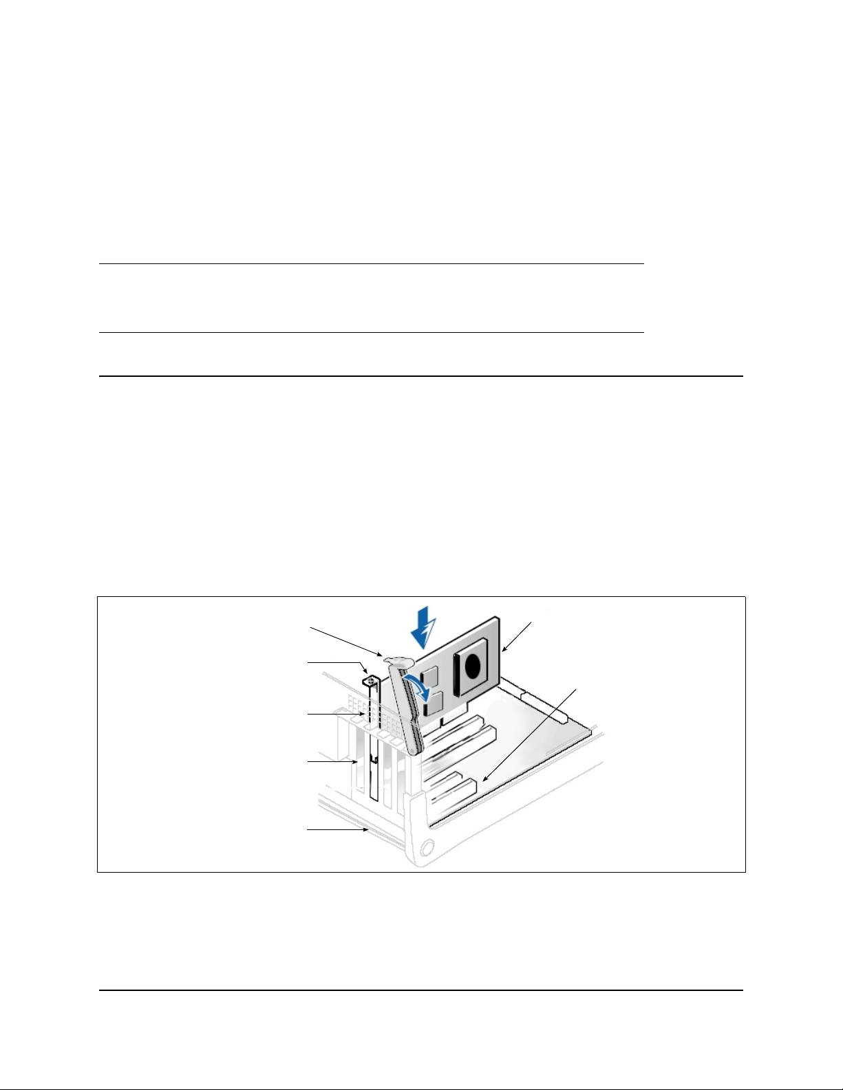
Step 1. Install the Adapter Hardware
To install the adapter hardware, you need to open the computer and locate the appropriate bus slot. If
necessary, consult your computer system manual for instructions on how to remove the computer cover.
Follow these steps to install the adapter hardwar e:
1. Power off the computer and all attached devices such as monitors, printers, and external components.
2. Disconnect the power cable.
3. Remove the computer cover and find an empty PCIe
4. Pull out the slot cover (if any) by removing the screw or releasing the lever.
5. Install the low-profile bracket (if required).
6. Grasp the adapter by the top edge and seat it firmly into the appropriate slot (see Figure i).
®
®
x8 (or larger) bus slot.
Figure i Illustration of Server Motherboard and Slots
7. Refasten the adapter’s retaining bracket using the existing screw or lever.
8. Close the computer cover.
9. Plug the appropriate Ethernet cable (either copper or optical) into the adapter.
8200 Series Converged Network Adapter and 3200 Series Intelligent Ethernet Adapter Page xv
Page 16

— Optical models ship with optical transceivers already installed. The 8200 and 3200 Series Adapters
will only operate with optical transceivers sold by QLogic.
— For direct-attach copper (DAC) connectivity, see the list of approved SFP+ DAC cables on QLo gic's
Web site:
http://www.qlogic.com/Resources/Documents/LineCards/Copper_Cables_Support_Matrix_Line_C
ard.pdf
— For twisted pair (RJ45) copper connectivity, the following cables/distances are supported for
10Gbps operation:
• Cat 7 shielded (100m)
• Cat 6A shielded/unshielded (100m)
• Cat 6 shielded/unshielded (55m)
1
10.Plug in the power cable and turn on the computer.
Step 2. Install the Adapter Drivers
To install the adapter drivers:
1. Go to the QLogic Driver Downloads/Documentation page at http://driverdownloads.qlogic.com.
2. Click QLogic Products.
3. Click Guided Search.
A window opens prompting you to Enter your search criteria.
4. Provide the information necessary:
a. In the Select a Product Type menu, select Adapters.
b. In the Select by Model or by OS, select by Model.
c. In the Select the Product Technology menu, select either Converged Network Adapters or
Intelligent Ethernet Adapters, as appropriate.
d. In the Select the Model menu, select your QLogic Adapter.
e. In the Select the Desired Item menu, select Drivers.
f. Click Search.
5. Scroll through the options that are shown; select th e ap pr op r iate driv er.
6. Click Download Now.
7. Follow the installation instructions included in the Readme file for the downloaded driver.
Step 3. Install QConvergeConsole
®
To install QConvergeConsole:
1. Go to the QLogic Driver Downloads/Documentation page at http://driverdownloads.qlogic.com.
2. Click QLogic Products.
3. Click Guided Search.
A window opens prompting you to Enter your search criteria.
4. Provide the information necessary:
1
Category 6 unshielded systems may be limited by alien crosstalk beyond 37-meter channels.
8200 Series Converged Network Adapter and 3200 Series Intelligent Ethernet Adapter Page xvi
Page 17

a. In the Select a Product Type menu, select Adapters.
b. In the Select by Model or by OS, select by Model.
c. In the Select the Product Technology menu, select either Converged Network Adapters or
Intelligent Ethernet Adapters, as appropriate.
d. In the Select the Model menu, select your QLogic Adapter.
e. In the Select the Desired Item menu, select Management Tools.
f. Click Search.
5. Scroll through the list that appears and select the QConvergeConsole version for your operating
system.
6. Click Download Now.
7. Follow the instructions in the QConvergeConsole Readme file for installing the downloaded software.
Step 4. Update the Flash
Download and update the QLogic adapter with the latest required version of the Flash Image from
http://driverdownloads.qlogic.com.
The Flash image package for the 8200 and 3200 Series Adapters includes boot code, firmware, and the
Flash update utility. For details on the package contents and update instructions, refer to the Readme file
on the QLogic Web site (http://driverdownloads.qlogic.com).
Additional Resources
• To obtain the most current drivers, management tools, multi-boot image, user instructions, and
documentation, please visit the QLogic Web site at http://driverdownloads.qlogic.com and download
the latest versions.
• See What’s in This Guide for descriptions of user instructions provided in this document.
• For important product information, including warranty, laser safety, and agency certification, and see
the Legal Notices section.
• For descriptions and procedures related to QConvergeConsole, use the built-in help system.
8200 Series Converged Network Adapter and 3200 Series Intelligent Ethernet Adapter Page xvii
Page 18

8200 Series Converged Network Adapter and 3200 Series Intelligent Ethernet Adapter Page xviii
Page 19

Chapter 1. Product Overview
What Is a Converged Network Adapter?
A Converged Network Adapter is a multifunction adapter that combines the capabilities of a Fibre Channel
adapter, an iSCSI adapter, and an Ethernet NIC. A Converged Network Adapter provides simultaneous
Fibre Channel, iSCSI, and Ethernet traffic over a shared 10Gb Ethernet link.
What Is an Intelligent Ethernet Adapter?
The Intelligent Ethernet Adapter is a multifunction adapter which, by default, supports one Ethernet
function per port and can be expanded to four Ethernet functions per port.
Function and Features
This section provides the following information:
• “Functional Description” on page 1
• “Features” on page 1
• “Supported Operating Systems” on page 2
Functional Description
The 8200 Series Adapters are Converged Network Adapters, and the 3200 Series Adapte rs are Intelligent
Ethernet Adapters (IEA). The 8200 Series Adapters support 210GbE Enhanced Ethernet, FCoE, and
iSCSI. The 3200 Series Adapters support 210GbE Enhanced Ethernet ports.
Features
The 8200 and 3200 Series Adapters provide the following features:
• NIC partitioning (NPAR)
• Message signaled interrupts (MSI-X)
• Device management for LAN and SAN
• Multi-boot capability including:
— Preboot-eXecution environment (PXE)
— iSCSI (8200 Series Adapters only)
— Fibre Channel (8200 Series Adapters only)
• PCIe 2.0 8
• User diagnostics that can be run from the CLI and the GUI
• Ethernet functions include:
—210 GbE
— Priority and virtual LAN (VLAN) tagging
— Jumbo frames up to 9618 bytes
— Advanced teaming
— VLAN configuration and management
— Preservation of teaming and VLAN configuration information during driver upgrade
8200 Series Converged Network Adapter and 3200 Series Intelligent Ethernet Adapter Page 1
Page 20

• Enhanced Ethernet functions include:
— Priority-based flow control (802.1Qbb)
— Enhanced transmission selection (802.1Qaz)
— Data center bridging exchange protocol (802.1Qaz)
— Link aggregatio n (8 02 .3a d)
• Advanced stateless offload features include:
— IP, TCP, and UDP checksums
— Large send offload (LSO)
— Large receive offload (LRO)
• QLogic FlexOffload
TM
stateful offload features (8200 Series only) include:
— iSCSI
—FCoE
• QLogic ConvergeFlex
TM
capability (8200 Series only) supports the following protocols simultaneously:
— TCP/IP
— iSCSI
—FCoE
• Several advanced management features for iSCSI and Fibre Channel adapters, including
QConvergeConsole (QCC) (GUI and CLI) and NIC partitioning (NPAR)
• Interrupt management and scalability features including:
— Receive side scaling (RSS)
— Interrupt moderation
— Flow control
— Locally administered address (LAA)
• Enhanced optimization with MSI, MSI-X, and NetQueue
Supported Operating Systems
The 8200 and 3200 Series Adapters support commonly used operating systems (OSs): Windows, Linux,
Solaris
For a detailed list of the currently supported operating systems, refer to the adapter’s Readme files on the
QLogic Web site: http://driverdownloads.qlogic.com
®
, and ESX®.
Adapter Specifications
Physical Characteristics
The 8200 and 3200 Series Adapters are implemented as low-profile PCIe cards. The adapters ship with a
full-height bracket for use in a standard PCIe slot or an optional spare low-profile bracket for use in a
low-profile PCIe slot. Low-profile slots are typically found in compact servers.
Standards Specifications
The 8200 and 3200 Series adapters support the following standards specifications:
• IEEE: 802.3ae (10 Gb Ethernet)
8200 Series Converged Network Adapter and 3200 Series Intelligent Ethernet Adapter Page 2
Page 21

• IEEE: 8021q (VLAN)
• IEEE: 802.3ad (Link Aggregation)
• IEEE: 802.1p (Priority Encoding)
• IEEE: 802.3x (Flow Control)
• IEEE: 802.1Qbb (Priority Based Flow Control)
• IEEE: 802.1Qaz (Enhanced Transmission Selection)
• IPv4 Specification (RFC791)
• IPv6 Specification (RFC2460)
• TCP/UDP Specification (RFC793/768)
• ARP Specification (RFC826)
• SCSI-3 Fibre Channel Protocol (SCSI-FCP)
• Fibre Channel Tape (FC-TAPE) Profile
• SCSI Fibre Channel Protocol-2 (FCP-2)
• Second Generation FC Generic Services (FC-GS-2)
• Third Generation FC Generic Services (FC-GS-3)
• iSCSI (RFC3720)
Environmental Specifications
The environmental specifications are listed in Table 1.
Table 1. Environmental Specifications
Condition Operating Non-Operating
Temperature Ranges
(for Altitude=900m or 2952.75ft)
Temperature Ranges
(for Altitude >900m or 2952.75ft)
Temperature Gradient Maximum per 60 min-
10°C to 55°C
(50°F to 131°F)
10°C to n°C b
(50°F to n°F
10°C 20°C
utes.
Humidity Percent Ranges—
Noncondensing
20 to 80 percent
(Max. Wet bulb temperature=
29°C)
Humidity Gradient Maximum
10 percent 10 percent
per 60 minutes
Altitude Ranges—Low Limits –15.2m (–50ft) –15.2m (–50ft)
Altitude Ranges—High Limits 3,048m (10,000ft) 10,668m (35,000ft)
Airborne Contaminants—ISA-71 Level
a
200LFM is required to operate at this temperature.
G1
a
–40°C to 65°C
(–40°F to 149°F)
–40°C to 65°C
c
)
(–40°F to 149°F)
5 to 95 percent
d
d
(Max. Wet bulb temperature=
38°C)
G1
d
d
8200 Series Converged Network Adapter and 3200 Series Intelligent Ethernet Adapter Page 3
Page 22

b
Use the following formulas to calculate the maximum oper ating temp erat ure (in °C) for a specific altitu de. Use the first formula if the altit ude is st ated in
meters and the second formula if the altitude is stated in feet.
c
Use the following formulas to calculate the maximum operating t emperatu re (in °F) for a specific alt itude . Use the fir st formul a if the alt itude is st ated in
meters and the second formula if the altitude is stated in feet.
d
Maximum corrosive contaminant levels measured at =50% relative humidity; see Table 3 in ISA-71.04-1985.
Converged Network Adapter SuperInstaller Installation
QLogic Windows SuperInstaller
For information about the QLogic Windows SuperInstaller, refer to the QLogic Windows SuperInstaller
Readme file on the QLogic Web site (http://driverdownloads.qlogic.com).
QLogic Linux SuperInstaller
For information about the QLogic Linux SuperInstaller, refer to the QLogic Linux SuperInstaller Readme
file on the QLogic Web site (http://driverdownloads.qlogic.com).
Multi-boot Image for 10Gb Converged Network Adapter—CNA
Function Configuration Utility
This section contains the following information:
• “Operating System Support” on page 4
• “Multi-boot Package Contents” on page5
• “Converged Network Adapter Function Configuration Package Contents” on page 5
• “Using QLflash” on page 5
— “Updating the Multi-boot Code” on page 5
— “QLflash Command Line Options” on page 5
— “Adapter Configuration Utility” on page 6
Operating System Support
This multi-boot code supports DOS, Windows Server® 2008; Solaris x86; and Linux on IA32, AMD64, and
®
x64-based systems. For information about the multi-boot image for your operating system, refer to
Intel
the corresponding Readme file on the QLogic Web site (http://driverdownloads.qlogic.com).
8200 Series Converged Network Adapter and 3200 Series Intelligent Ethernet Adapter Page 4
Page 23

Multi-boot Package Contents
The multi-boot package for 8200 and 3200 Series Adapters is a compressed file that contains the
82xx/32xx BIOS, PXE, and firmware. This package also includes the QLflash application.
Converged Network Adapter Function Configuration Package Contents
The following files are included for updating the adapter multi-boot code:
• update.bat—DOS batch file that calls the executable files to update the adapter multi-boot.
• QLflash.exe—Utility to update multi-boot code and firmware.
• DOS4GW.exe—This file is required to use the QLflash.exe.
• p3pyyyyy.bin—Combined binary file, which includes the binaries for the BIOS, PXE, and firmware.
Using QLflash
QLflash is a native DOS utility. For more information about QLflash, refer to the Multi-Boot Image
Readme file. To run this utility, boot to a DOS hard drive or USB removable drive.
Utility Version:
/VER = Display version of the QLflash utility
Help Options:
/? = Help menu
Updating the Multi-boot Code
To write the multi-boot code to Flash memory:
1. Insert the QLogic Adapter in the system.
2. Boot to DOS.
3. Run the update script at the command prompt:
C:\>update.bat
This script program updates the multi-boot image on the adapter.
4. Reboot the system.
Note: You can also use the QConvergeConsole (QCC) GUI/CLI to flash the multi-boot image. After
the multi-boot code is updated, power cycle the server for the new changes to take effect.
QLflash Command Line Options
The executable file QLflash.exe is used by the UPDATE.BAT file to update your adapter multi-boot
code. The application QLflash.exe may be used to read, write, or verify either the multi-boot image or
the NVRAM on the adapter .
The following paragraphs describe the command line options available with this utility. Use of QLflash will
modify the way your adapter operates, and it must be used with extreme caution.
Certain features (that is, the NVRAM options) may require additional data.
Files and passwords are not provided in this file.
8200 Series Converged Network Adapter and 3200 Series Intelligent Ethernet Adapter Page 5
Page 24

QLflash Options
QLflash.exe <1...N | ALL> [options]
/SLT
SLT: Sets the application to silent mode
Use application return code for success or failure
/SIL=filename.ext
SIL: Load multiflash image from file
/PRV | /VPP | /PRN
PRV: Print firmware versions
VPP: Print VPD contents
PRN: Print MAC addresses and worldwide port name (WWPN)
/CFU=filename.ext | /CFS=filename.ext | /CFC=filename.ext
CFU: Flash board configuration from file
CFS: Save board configuration file (need template file BRDCFG.DAT)
CFC: Compare board configuration to a binary file
/NVU=filename.ext | /NVS=filename.ext | /NVC=filename.ext
NVU: Flash NVRAM from file
NVS: Save NVRAM to file (need template file NVRAM.DAT)
NVC: Compare Flash to NVRAM file
/UIL=filename.ext | /UIS=filename.ext | /UIC=filename.ext
UIL: Flash user information data from file
UIS: Save user information data to file
UIC: Compare user information data to a binary file
Note: • If you used an FC RAID target in a cluster environment, you sh ould enable the
Enable Target Reset = Enabled (Advanced Adapter Settings).
• Use the /I option if the update utility, QLflash, does not detect your adapter.
• QLogic recommends disabling the internal disk before installing the OS or
booting to the FCoE disk.
Adapter Configuration Utility
Note: The CNA Function Configuration utility does not run on SUN™ SPARC® systems.
This section provides detailed configuration information for advanced users who want to customize the
configuration of the 8200 and 3200 Series Adapters and the connected devices. You can configure the
adapters using the CNA Function Configuration utility.
8200 Series Converged Network Adapter and 3200 Series Intelligent Ethernet Adapter Page 6
Page 25

To access the CNA Function Configuration utility , press ALT+Q during the adapter initialization (it may take
a few seconds for the menu to appear). If you have more than one adapter, the utility will ask you to select
the adapter you want to configure. After changing the settings, the utility reboots your system to load the
new parameters.
Caution: If the configurati on settings are incorrect, your adapter may not function properly.
Upon entering the CNA Function Configuration utility, the following selections are available from the Setup
Menu/Function Configuration menu:
• “Type” on page 7
• “MinBW%” on page 7
• “Protocol” on page 7
• “Restore to Non-NIC Partition Settings” on page 7
• “Exit the CNA Function Configuration Utility” on page 8
Type
Enter to set a function to a particular type:
• NIC—The function will support NIC protocol.
• None—The function will be disabled.
• iSCSI—The function will support iSCSI protocol.
• FCoE—The function will support FCoE protocol.
Note: Functions 0 through 3 support only NIC or None. Functions 4 and 5 support NIC, iSCSI, or
None. Functions 6 and 7 support NIC, FCoE, or None.
MinBW%
Enter to specify the percentage of bandwidth allocated to the function. The combined MinBW% values for
a port’s functions cannot exceed 100 percent.
Protocol
The Protocol parameter applies only to only function 0 and function 1.
• PXE—PXE will be supported on the NIC.
Adapter Settings Press the ENTER key on the Function number to access Adapter Settings, and to
configure PXE Boot.
PXE The following settings are available when Protocol is set to PXE:
• Setup Menu Wait Time (0–15: the default is 5 seconds)
Specifies the time in seconds the menu will wait.
• Enable PXE Boot (Enabled/Disabled: Default—Disabled)
Enter to toggle between Enabled and Disabled. Use the Enable PXE Boot option to attempt a
PXE boot on the selected function.
Restore to Non-NIC Partition Settings
Press the ENTER key to restore the NIC partition settings.
8200 Series Converged Network Adapter and 3200 Series Intelligent Ethernet Adapter Page 7
Page 26
Exit the CNA Function Configuration Utility
Press the ENTER key to select from the following:
• Reboot System
• Return to Fast!UTIL
Installing the QLogic Adapter vCenter Plug-in for ESX/ESXi
This section on installing the QLogic Adapter vCenter Plug-in contains the following:
• “Introduction” on page 8
• “Requirements” on page 9
• “Installing the QLogic Adapter CIM Provider” on page 9
• “Starting the QLogic Adapter CIM Provider” on page 11
• “Removing the QLogic Adapter CIM Provider” on page 11
• “Starting the QLogic Adapter vCenter Plug-in” on page 12
• “Removing the QLogic Adapter vCenter Plug-in” on page 12
• “Installing the Flash Utility” on page 12
• “Updating the Flash” on page 13
• “Using the vCenter Plug-in on a Tomcat Server” on page 13
• “Plug-in Unregistration from a Manual Installation” on page 15
• “Launching the Plug-in from vSphere Client” on page 15
Introduction
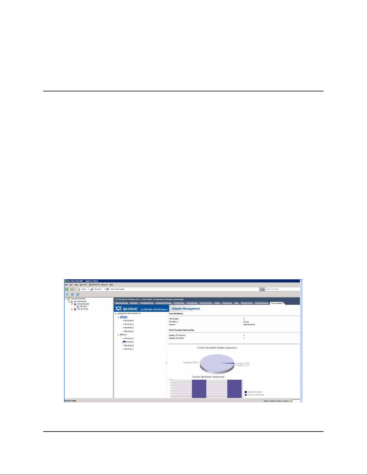
The QLogic Adapter vCenter Plug-in is a user-interface extension to the vSphere™ Client that allows you
to manage and configure QLogic adapters, including the NIC partitioning feature, on ESX and ESXi
servers. When the you select an ESX or ESXi host that has QLogic adapters installed, the extension
appears in the client as an additional tab named QLogic Adapter, as shown in Figure 1.
Figure 1: vSphere Client Showing QLogic Adapter Tab
8200 Series Converged Network Adapter and 3200 Series Intelligent Ethernet Adapter Page 8
Page 27
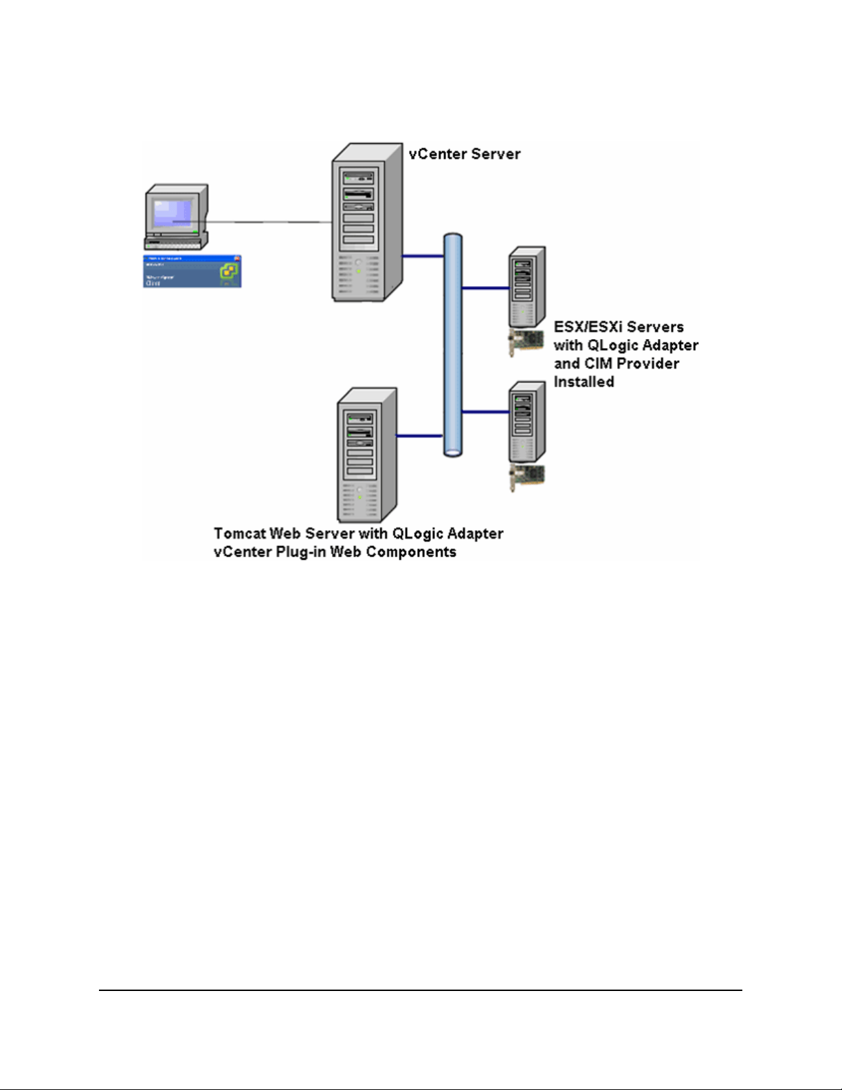
Requirements
The QLogic Adapter vCenter Plug-in requires the components in Figure 2 to be installed and running.
Figure 2: vCenter Plug-in Requirements
QLogic provides the following components that must be installed on the ESX or ESXi Server, vCenter
Server , and Tomcat Web Server.
ESX/ESXi Server
• QLogic Adapter with firmware and driver
• QLogic Adapter CIM Provider
vCenter Server
• QLogic XML configuration file to register the plug-in to the vCenter Serv er
Tomcat Web Server
• QLogic Web-based extension to the vSphere Client
Installing the QLogic Adapter CIM Provider
The QLogic Adapter CIM Provider for VMware ESX wa s generated as a vSphere In stallation Bundle (VIB)
file. A VIB contains the complete set of files and binaries required to install the provider on VMware
ESX/ESXi. The offline-bundle.zip file contains the VIB and the necessary metadata to install the
provider on VMware ESX/ESXi.
8200 Series Converged Network Adapter and 3200 Series Intelligent Ethernet Adapter Page 9
Page 28

This section provides the following installation procedures for the CIM Provider:
• Initial Installation
• Subsequent Update Installation
Initial Installation
To install the QLogic Adapter CIM Provider using the esxupdate command (ESX systems only):
1. Copy the offline-bundle.zip file into the root directory (/) of the ESX system.
2. Issue the esxupdate command as follows:
# cd /
# esxupdate --bundle offline-bundle.zip --nodeps –nosigcheck --maintenancemode update
To install the QLogic Adapter CIM Provider from a remote host using the vSphere CLI vihostupdate
command (ESXi systems only):
Note: To update the provider from a remote host using the vihostupdate command, make sure
that the ESXi system is in maintenance mode. To put the ESXi host in maintenance mode
using vSphere Client, select Inventory, select Host, and then select Enter Maintenance
Mode.
1. Copy the offline-bundle.zip file to any location on the host where either the vSphere CLI
package is installed or the vSphere Management Assistant (vMA) is hosted.
2. Navigate to the location of the offline-bundle.zip file.
3. Issue the vihostupdate command to install the offline bundle as follows:
# vihostupdate.pl <conn_options> --install --bundle
offline-bundle.zip --nosigcheck
For available options, refer to the vihostupdate page.
4. Follow the on-screen instructions to complete the installation. You may need to reboot the ESXi
system.
Note: For more details on vihostupdate, refer to the documents on the VMware vSphere
Command-Line Interface Documentation page, located here:
http://www.vmware.com/support/developer/vcli/.
Subsequent Update Installation
To update the QLogic Adapter CIM Provider after a prior VIB installation:
1. Follow the instructions in “Removing the QLogic Adapter CIM Provider” on page 11 to remove the
existing VIB.
2. Follow the instructions in “Initial Installation” on page 10 to install the new VIB.
8200 Series Converged Network Adapter and 3200 Series Intelligent Ethernet Adapter Page 10
Page 29

Starting the QLogic Adapter CIM Provider
After a system startup, the Small Footprint CIM Broker (SFCB) CIM object manager (CIMOM) in the ESX
system should start automatically and load the QLogic Adapter CIM Provider when necessary.
For ESX systems, you can also manually stop, start, or restart the SFCB CIMOM by issuing the following
commands.
To stop the SFCB CIM O M an d th e QLog ic Ada p te r CIM Prov ide r:
# /etc/init.d/sfcbd-watchdog stop
To start the SFCB CIMOM and the QLogic Adapter CIM Provider:
# /etc/init.d/sfcbd-watchdog start
To restart the SFCB CIMOM and the QLogic Adapter CIM Provider:
# /etc/init.d/sfcbd-watchdog restart
After starting the SFCB CIMOM, use a CIM client utility to query the QLogic Adapter CIM Provider for
information.
Removing the QLogic Adapter CIM Provider
To remove the QLogic Adapter CIM Provider, use either the esxupdate or vihostupdate command.
To uninstall the QLogic Adapter CIM Provider using the esxupdate command:
1. Query and find the existing VIB you are updating as follows:
# esxupdate query --vib-view | grep qlogic
For example, the VIB ID may have a format similar to the following:
ESX/ESXi 4.0: cross_qlogic-nic-provider_400.x.x.x-000000
ESX/ESXi 4.1: cross_qlogic-nic-provider_410.x.x.x-000000
where x.x.x is the version number of the existing provider.
2. Remove the existing VIB as follows:
# esxupdate remove -b <vibID>
To uninstall from a remote host using the vihostupdate command:
Note: To uninstall the provider from a remote host using the vihostupdate command, make sure
that the ESX/ESXi system is in maintenance mode. To put the ESX/ESXi host in
maintenance mode using vSphere Client, select Inventory, select Host, and then select
Enter Maintenance Mode.
1. From a console on the host where the vS pher e CLI package is inst alled or vMA is hosted, query to find
the Bulletin ID of the existing provider:
# vihostupdate.pl <conn_options> --query\
For example, the Bulletin ID may have a format similar to the following:
ESX/ESXi 4.0: QLGC_NIC_PROVIDER-ESX-4.0.0-qlogic-nic-provider-x.x.x
ESX/ESXi 4.1: QLGC_NIC_PROVIDER-ESX-4.1.0-qlogic-nic-provider-x.x.x
where x.x.x is the version number of the existing provider.
8200 Series Converged Network Adapter and 3200 Series Intelligent Ethernet Adapter Page 11
Page 30

2. Remove the existing VIB as follows:
# vihostupdate.pl <conn_options> --remove --bulletin <bulletinID>
Note: For more details on vihostupdate, refer to the documents on the VMware vSphere
Command-Line Interface Documentation page, located here:
http://www.vmware.com/support/developer/vcli/
Starting the QLogic Adapter vCenter Plug-in
To start the QLogic Adapter vCenter Plug-in:
1. Start the VMware vSphere Client and connect to the vCenter Server by entering the IP address or
name, user name, and password.
2. Click Login.
3. If the Security Warning dialog box appears, click Ignore to use the current SSL certificate.
• If you start and connect the vSphere Cl ient directly to an ESX/ESXi server , the vCenter plug-in does
not open.
• If you have not already done so, create a data center and add the ESX server.
4. In the left pane, select the IP address of the VMware server.
5. In the right pane, click the QLogic Adapter tab to view the Web page.
The vCenter plug-in retrieves the adapter information from the server.
Note: If the server does not have the QLogic Adapter CIM Provider and adapters installed,
or if the vCenter Plug-in installation and registration was not successful, the QLogic
Adapter tab is not shown.
Removing the QLogic Adapter vCenter Plug-in
To remove the QLogic Adapter vCenter Plug-in:
1. In the Windows Control Panel, select Add or Remove Programs.
2. In the Add or Remove Programs dialog box, select the QLogic Adapter vCenter Plug-in, and then
click Change/Remove.
3. Follow the instructions in the QLogic Adapter vCenter Plug-in installer to remove the plug-in.
Installing the Flash Utility
For ESX, before you perform a Flash update on QLogic Adapters using the QLogic Adapter vCenter
Plug-in, ensure that the QLflash utility is also installed on the ESX system.
To install the QLflash utility on ESX:
1. Unzip the esx_qlflash.zip file, which contains the qlflash userworld executable.
2. Copy the QLflash binary file to the /usr/lib/vmware/bin/ directory.
3. Add executable permission for QLflash by issuing the following command:
# chmod +x qlflash
4. If it does not already exist, edit and append the /usr/lib/vmware/bin/qlflash entry in the
/etc/vmware/UserWorldBinaries.txt file.
For ESXi, the QLflash utility is not required, so no additional steps are necessary.
8200 Series Converged Network Adapter and 3200 Series Intelligent Ethernet Adapter Page 12
Page 31

Updating the Flash
Note: For ESX systems, before you perform a Flash update on a QLogic Adapter using the vCenter
Plug-in, ensure that the QLflash utility is also installed. Follow the instructions in the Installing
the Flash Utility section.
To update th e Fla s h f rom th e QL og ic Ada p ter v Cen te r Plug - in:
1. Follow the instructions in “Starting the QLogic Adap ter vCenter Plug-in” on p age 12 to start the vCenter
plug-in.
2. In the left pane of the QLogic Adapter page, select the adapter, and then click the Update Adapter
Flash Image link.
3. In the Select Flash File for Update dialog box, click Browse.
4. In the Choose File to Upload dialog box, select the .bin Flash file from the extracted Flash kit package
that is compatible with your adapter, and then click Open.
5. In the Select Flash File for Update dialog box, click Send.
6. Verify the current Flash version and file version, and then click OK to continue the update.
7. When asked “Do you want to reset the adapter to activate the firmware immediately after successful
update?,” click OK if you want the new firmware to take ef fect immediately. Or, click Cancel to have the
new firmware take effect after the next system reboot.
8. Wait for the Flash update process to complete. Processing time depends on the network connection
and the system configuration. Do not interrupt the update process.
Caution: The Flash update may take up to 10 minutes to complete. Do not cancel the task or
reboot the server during this time. Doing so may corrupt the firmware on the
adapter.
9. In the Flash update successful completion message box, click OK.
10.If you clicked OK in step 7 on page 13, you can click Refresh to verify the new firmware version.
Otherwise, you must reboot the system for the new firmware to take effect.
Using the vCenter Plug-in on a Tomcat Server
VMware requires that all vCenter plug-ins are web-based applications hosted on a Tomcat Server , which
can be downloaded and installed on Linux and Windows systems. Here is a link to Tomcat:
http://tomcat.apache.org.
The QLogic vCenter Plug-in supports Tomcat 5, 6, and 7. The installer dynamically detects the Tomcat
version and installs accordingly.
This section provides the following procedures for using the vCenter Plug-in on a Tomcat Server:
• “Installing Tomcat on Linux” on page 13
• “Starting and Stopping Tomcat on Linux” on page 14
• “Installing Tomcat on Windows” on page 14
• “Starting and Stopping Tomcat on Windows” on page 14
Installing Tomcat on Linux
To install Tomcat on a Linux OS:
1. Go to the following URL:
http://tomcat.apache.org/download-55.cgi
8200 Series Converged Network Adapter and 3200 Series Intelligent Ethernet Adapter Page 13
Page 32

2. Locate the following directory and file:
Binary Distribution > Core > tar.gz (apache-tomcat-5.5.28.tar.gz)
3. Unzip the tar.gz file by issuing the following command:
root # tar zxf file.tar.gz
4. Create a symbolic link to a Tomcat directory by issuing the following command:
# ln -s apache-tomcat-5.5.28 tomcat
where setting variables include the following:
export JAVA_HOME=/root/gwt/jdk1.6.0_17/
export CATALINA_HOME=/root/gwt/tomcat/
Starting and Stopping Tomcat on Linux
To start Tomcat, issue the following command:
# $CATALINA_HOME/bin/startup.sh
To stop Tomcat, issue the following command:
# $CATALINA_HOME/bin/shutdown.sh
Installing Tomcat on Windows
To install Tomcat on a Windows OS:
1. Go to either of the following URLs:
http://tomcat.apache.org/download-60.cgi
http://tomcat.apache.org/download-70.cgi
2. Locate the following directory and file:
Binary Distribution > Core > 32-bit/64-bit Windows Service Installer
3. To install the Tomcat service, get the 32-bit/64-bit Windows Service Installer, save it, and run it.
Starting and Stopping Tomcat on Windows
To start and stop Tomcat on a Windows OS:
1. Go to Computer Management > Services and Application > Services > Apache To mcat <version
number>.
2. Right-click, and then select Start /Stop to initiate Tomcat service, or select Stop to halt the Tomcat
service.
Installing the vCenter Plug-in on Tomcat
To install the vCenter Plus-in on a Tomcat Server:
1. Download the QLogic Adapter vCenter Plug-in installer EXE; for example, QLogic Adapter VI
Plugin 1.0.4.exe.
2. Run the installer by double-clicking the EXE file or by typing the name of the EXE on a command
prompt.
The InstallAnywhere installer prepares to install the QLogic Adapter vCenter Plug-in.
3. On the Introduction window, click Next.
8200 Series Converged Network Adapter and 3200 Series Intelligent Ethernet Adapter Page 14
Page 33

4. On the Please Wait window, wait while the QLogic Adapter vCenter Plug-in is configured for your
system.
5. On the Choose Install Folder window, either accept the default installation directory, or click Choose to
specify a different folder.
6. Click Install to install files to the installation directory specified in the previous step.
A progress window shows the status of the installation.
7. On the User Input window, type your vCenter Server IP address, username, and password, as well as
the IP address of your local Tomcat Server. Then click Next to continue.
8. On the Please Wait window, wait while the QLogic Adapter vCenter Plug-in is configured for your
system and registers the plug-in with the vCenter Server.
9. On the Registration Result window, click Finish to complete the plug-in installation.
Plug-in Unregistration from a Manual Installation
If you have performed a manual installation of the vCenter plug-in, you must perform a manual uninstall
before running the vCenter installation wizard.
VMware provides two type of scripts for vCenter plug-in registration:
• For Windows PowerShell
• For Perl: http://communities.vmware.com/docs/DOC-4530
1. Before you can use the script, download the appropriate VI SDK from VMware.
• For PowerShell, download vSphere PowerCLI:
http://communities.vmware.com/community/vmtn/vsphere/automationtools/powercli
• For Perl VI SDK, download vSphere SDK for Perl:
http://www.vmware.com/support/developer/viperltoolkit/
2. After you download and install the SDK and the registration script, follow the VMware instructions to
register the vCenter Plug-in.
For example, the Perl unregister command is:
perl registerPlugin.pl --server="127.0.0.1" -username="administrator"
--password="password" --key="com.qlogic.QLogicAdapterVIPlugIn" --action="remove"
®
scripting: http://communities.vmware.com/docs/DOC-4521
3. Replace the username and password with the correct information to log into the vCenter Server.
Launching the Plug-in from vSphere Client
To launch the plug-in from vSphere client:
1. Start the vSphere Client and connect to the vCenter Server. (If you start and connect the vSphere Client
directly to an ESX or ESXi server, the vCenter plug-in does not appear.)
2. If you have not done so, create a data center and add the ESX server.
3. In the left pane, select the server.
A row of tabs appear in the right pane. If the server has QLogic Adapter CIM Provider and adapters
installed, and if the vCenter plug-in installation and registration were successful, the QLogic Adapter
tab appears in the tab row.
4. Click the QLogic Adapter tab to view a web page.
8200 Series Converged Network Adapter and 3200 Series Intelligent Ethernet Adapter Page 15
Page 34

8200 Series Converged Network Adapter and 3200 Series Intelligent Ethernet Adapter Page 16
Page 35

Chapter 2. Configuring NIC
This chapter describes the driver and QConvergeConsole (QCC) agent installation, configuration,
operation, and troubleshooting of the NIC function of the 8200 and 3200 Series Adapters. For information
about QCC Agents, refer to the QCC User’s Guide.
Installing NIC in Linux
For information about packaging content, Linux OS support, supported features, driver installation, driver
removal, and driver system parameters, refer to the Ethernet Networking Driver Readme file (Intelligent
Ethernet Adapter and Converged Network Adapter Inbox Driver Update on the QLogic Web site
http://driverdownloads.qlogic.com.
Installing NIC in ESX/ESXi
For information about packaging content, ESX OS support, driver installation, and driver removal, refer to
the Networking Driver Readme file (Intelligent Ethernet Adapter and Converged Network Adapter
Networking Driver for ESX/ESXi) on the QLogic Web site http://driverdownloads.qlogic.com.
Installing NIC in Windows
For information about packing content, Windows OS support, driver installation, and driver removal, refer
to the Ethernet Networking Driver Readme file (Intelligent Ethernet Adapter and Converged Network
Adapter NDIS Miniport Driver for Windows) on the QLogic Web site http://driverdownloads.qlogic.com.
Configuring PXE Boot
This section provides procedures for configuring the 8200 and 3200 Serie s Adapters to perform PXE bo ot.
The example uses function 1 and NIC 1.
To configure PXE boot:
1. Enter the system BIOS by pressing the F2 key.
2. On the BIOS window (Figure 3), select Integrated Devices, and then press the ENTER key.
Figure 3: Dell BIOS: Integrated Devices
8200 Series Converged Network Adapter and 3200 Series Intelligent Ethernet Adapter Page 17
Page 36

3. Set the Embedded NIC1 and NIC2 option to Enabled.
4. Set the Embedded NIC1 option to Enabled with PXE.
5. Press the ESCAPE key twice, and then select Save changes and exit.
The system reboots.
6. (Optional) During POST , press the CTRL+Q keys to enter the QLogic 8200 Series / 3200 Series CNA
Function Configuration window.
7. On the CNA Function Configuration main window, ensure that Protocol is set to PXE (Figure 4).
Figure 4: QLogic 8200 CNA Function Configuration
8. Press the ESC key to exit.
9. Select Save changes to save your edits, exit, and reboot the system.
10.During POST, press the F2 key to enter the BIOS system.
11. Select Boot Settings, and then press the ENTER key (Figure 5).
Figure 5: Dell BIOS: Boot Settings
8200 Series Converged Network Adapter and 3200 Series Intelligent Ethernet Adapter Page 18
Page 37

12.Select the Boot Sequence option, and then press the ENTER key.
13.Select the Embedded NIC 1 QLogic PXE... entry, and then press the UP ARROW key to move this
entry to the first position (Figure 6).
Figure 6: Embedded NIC 1 QLogic PXE
14.Press the ESCAPE key, and then select Save changes and exit.
The system reboots.
15.After the system reboot, follow the screen prompt for PXE boot server for the installation of OS of your
choice.
Configuring Driver Software Parameters
Linux NIC Driver Management Applications
The following sections describe how to configure and manage the driver and adapter using the qaucli and
ethtool Linux management utilities.
qaucli Utility
Install QConvergeConsole CLI (qaucli) from the following packages supplied by QLogic:
• QConvergeConsoleCLI-<version>_linux_<arch>.install.tar.gz—Package file
• QConvergeConsoleCLI-<version>_<arch>.rpm—RPM installer package file
Example RPM Package Installation To determine if QCC is installed and to find the full name of the
installed QCC RPM package, issue the following command using the partial name
QConvergeConsoleCLI as an argument to grep:
rpm –qa | grep QConvergeConsoleCLI
1. To check for an older version of the RPM package, issue the following command:
rpm –qa QConvergeConsoleCLI
2. If an older version is found, erase that version by issuing the following command:
rpm –e QConvergeConsoleCLI
8200 Series Converged Network Adapter and 3200 Series Intelligent Ethernet Adapter Page 19
Page 38

3. To install the new version, issue the following command:
rpm –ihv QConvergeConsoleCLI-1.0.00-04.i386.rpm
The utility is installed in the /opt/QLogic_Corporation/QConvergeConsoleCLI directory.
ethtool Utility
Use the ethtool utility to view adapter statistics and configure interface options. For additional details,
refer to qlcnic driver man page and ethtool man page.
To disable transmit segmentation offload, issue the following command, where [n] represen ts a numerical
value for a specific instance:
ethtool -K eth[n] tso off
To list interface statistics, issue the following command, where [n] represents a numerical value for a
specific instance:
ethtool –S eth[n]
Sample Output 1:
ethtool -S eth8
NIC statistics:
xmit_called: 6
xmit_finished: 6
rx_dropped: 0
tx_dropped: 0
csummed: 0
rx_pkts: 0
lro_pkts: 0
rx_bytes: 0
tx_bytes: 468
lrobytes: 0
lso_frames: 0
xmit_on: 0
xmit_off: 0
skb_alloc_failure: 0
null skb: 0
null rxbuf: 0
rx dma map error: 0
In the following example, ethtool eth[n] lists interface settings.
Sample Output 2:
Ethtool eth8
Settings for eth8:
Supported ports: [ TP FIBRE ]
Supported link modes:
Supports auto-negotiation: No
Advertised link modes: 10000baseT/Full
Advertised auto-negotiation: No
Speed: 10000Mb/s
Duplex: Full
Port: FIBRE
PHYAD: 1
Transceiver: external
Auto-negotiation: off
Supports Wake-on: g
Wake-on: g
8200 Series Converged Network Adapter and 3200 Series Intelligent Ethernet Adapter Page 20
Page 39

Current message level: 0x00000000 (0)
Link detected: yes
QLogic Device Windows Property Pages
To access the property pages in Windows:
1. Access the Device Manager as follows:
a. On the Windows desktop, click Start, Control Panel, click Administrative Tools, and then click
Computer Management.
b. In the Computer Management dialog box, click Device Manager.
2. In the left pane of the Device Manager dialog box, right-click QLogic 10Gb Ethernet Adapter, and
then click Properties.
3. On the adapter properties dialog box, click the Advanced tab to bring that page to the front.
4. On the Advanced page, configure the parameters specified in the Table 2.
5. (Optional) Click other tabs to bring those pages to the front and view or change settings, for example:
— Click the Information tab to view the configuration.
— Click the Details tab to view NIC driver details. On the Details page, click items under Property to
view the selected item's value.
— Click the Driver tab to update, rollback, disable, or uninstall the NIC driver.
— Click the Resource tab to view resource settings.
— Click the Statistics tab to view the transmit and receive (g eneral and QLog ic-customized) st atistics
gathered while the NIC is operational.
6. When you are through viewing and chang ing driver prope rties, click OK to close the dialog box, or click
Cancel to revert to the previous driver configuration.
Table 2. Windows Driver Configurable Parameters
Property Description
Completion Queue Size Specifies the size for the ring where command completion and incoming receive
indication status will be posted.
Registry Key: CompletionQueueSize
Default: 16384
Values: 1024, 2048, 4096, 8192, 16384, 32768
Flow Control Sets the hardware flow control parameters.
Registry Key: *FlowControl
Default: Rx and Tx Enabled
Values: Disabled, Rx Enabled, Tx Enabled, Rx and Tx Enabled
Health Monitoring Checks health of firmware, monitors normal operation, and ensures recovery of
the firmware.
Interrupt Moderation Allows interrupt coalescing during receive and transmit operation.
Registry Key: *InterruptModeration
Default: Disabled
Values: Enabled, Disabled
8200 Series Converged Network Adapter and 3200 Series Intelligent Ethernet Adapter Page 21
Page 40

Table 2. Windows Driver Configurable Parameters (Continued)
Property Description
IPv4 Checksum Offload Enables and disables IPv4 checksum offload.
Registry Key: *IPChecksumOffloadIPv4
Default: Rx and Tx Enabled.
Values: Disabled, Rx and Tx Enabled, Rx Enabled, Tx Enabled
Large Receive Offload Enables and disables TCP large receive offload. Enables colla psing of multiple
MTU size TCP packets into bigger segments before handing these over to the
host.
Registry Key: LRO
Default: Enabled
Values: Enabled, Disabled
Large Send Offload V1 IP4 Enables and disables TCP large send offload. Allows host TCP stack to give big-
ger than maximum segment size (MSS) packets to the driver, and then with the
help of hardware, splits the larger segments into MTU size packets before sending
them on the wire.
Registry Key: *LsoV1IPv4
Default: Enabled.
Values: Enabled, Disabled
Size of LSO v1: 64K
Large Send Offload V2 IP4 Enables and disables TCP large send offload. Allows the host TCP stack to give
bigger than MSS packets to the driver, and then with the help of hardware, splits
the larger segments into MTU size packets before sending them on the wire.
Registry Key: *LsoV2IPv4
Default: Enabled
Values: Enabled, Disabled
Size of LSO v2: 128K
Large Send Offload V2 IP6 Enables and disables TCP large send offload. Allows host TCP stack to give big-
ger than MSS packets to the driver, and then with the help of hardware, splits the
larger segments into MTU size packets before sending them on the wire.
Registry Key: *LsoV2IPv6
Default: Enabled
Values: Enabled, Disabled
Size of LSO v2: 128K
Locally Administered Address Defines the locally administered address (LAA) that users and administrators can
set on this interface. This address overrides the permanent address of the QLogic
adapter (that may have been Flashed into the hardware).
Registry Key: NetworkAddress
Format: Hexadecimal
Options: Value (a value is required, enter the 12 hex bytes of the MAC address to
be used), or not present.
8200 Series Converged Network Adapter and 3200 Series Intelligent Ethernet Adapter Page 22
Page 41

Table 2. Windows Driver Configurable Parameters (Continued)
Property Description
Max Ethernet Frame Size Specifies the Ethernet frame size for packet transmission and receipt (includes the
MAC header).
Reg Key: MaxFrameSize
Default: 1514 (corresponds to 1514 bytes on the wire + 4 bytes of CRC)
Max: 9614
Min: 142 (Windows 2003), 590 (Windows 2008)
Max Jumbo Buffers Specifies the number of jumbo-sized receive buffers allocated for the jumbo ring
(not frame).
Reg Key: RxJumboRingSize
Default: 4096
Values: 1024, 2048, 4096, 8192
Number of Receive Buffers Specifies the number of buffers allocated for receiving standard MTU size (1514
byte) packets.
Registry Key: *ReceiveBuffers
Values: 1024, 2048,4096,8192,16384,32768
Default: 16384
Number of Transmit Buffers Specifies the number of stage buffers used by the driver during transmit.
Registry Key: *TransmitBuffers
Values: 1024, 2048, 4096
Default: 1024
Priority & VLAN Tag Enables and disables support for 802.1pQ priority tagging. This property must be
enabled to set the VLAN ID.
Registry Key: PQTagging
Default: Priority & VLAN Enabled
Values: Priority & VLAN Enabled; Priority & VLAN Disabled; Pri-
ority Disabled, VLAN Enabled; Priority Enabled, VLAN Disabled
Receive Side Scaling Enables and disables the RSS feature.
Registry Key: RSS
Default: Enabled
Values: Enabled, Disabled
Receive Side Scaling Rings Specifies the number of RSS rings used.
Registry Key: MaxStatusRings
Default: 2
Values: 1-4
TCP Checksum Offload IPv4 Enables and di sables the TCP transmit and receive checksum offload.
Registry Key: *TCPChecksumOffloadIPv4
Default: Rx and Tx Enabled
Values: Disabled, Rx Enabled, Tx Enabled, Rx and Tx Enabled
8200 Series Converged Network Adapter and 3200 Series Intelligent Ethernet Adapter Page 23
Page 42

Table 2. Windows Driver Configurable Parameters (Continued)
Property Description
TCP Checksum Offload IPv6 Enables and disables the TCP transmit and receive checksum offload.
Registry Key: *TCPChecksumOffloadIPv6
Default: Rx and Tx Enabled
Values: Disabled, Rx Enabled, Tx Enabled, Rx and Tx Enabled
UDP Checksum Offload IPv4 Enables and the disables the user datagram protocol (UDP) transmit and receive
checksum offload.
Registry Key: *UDPChecksumOffloadIPv4
Default: Rx and Tx Enabled
Values: Disabled, Rx Enabled, Tx Enabled, Rx and Tx Enabled
UDP Checksum Offload IPv6 Enables and disables the UDP transmit and receive checksum offload.
Registry Key: *UDPChecksumOffloadIPv6
Default: Rx and Tx Enabled
Values: Disabled, Rx Enabled, Tx Enabled, Rx and Tx Enabled
VLAN ID for Setting If the Priority and VLAN Tag is enabled, this parameter specifies a VLAN ID for this
interface (also exposed through the standard object identifier (OID)).
Registry Key: VlanId
Default: 0 (no VLAN)
Range: 0-4094
Configuring NIC Driver Parameters with QCC GUI
For information about configuring NIC driver parameters with the QCC GUI, refer to the
QConvergeConsole Help System: Setting Gene ra l NIC Por t Param e te rs an d Set tin g Adv anc ed NIC Port
Parameters.
Configuring NIC Driver Parameters with QCC Interactive CLI
For information about configuring NIC driver parameters with the QCC interactive CLI, refer to the
QConvergeConsole CLI User's Guide: section 7, “NIC Interactive Commands,” on the QLogic Web site
(http://driverdownloads.qlogic.com).
Configuring NIC Driver Parameters with QCC Non-Interactive CLI
Refer to the QConvergeConsole CLI User's Guide, section 4, “NIC Noninteractive commands,” on the
QLogic Web site (http://driverdownloads.qlogic.com).
VLAN Configuration
VLAN Configuration with QCC GUI
For information about VLAN configuration with the QCC CLI, refer to the QConvergeConsole Help System:
Setting Advanced NIC Port Parameters.
VLAN Configuration with the QCC Interactive CLI
For information about VLAN configuration with the QCC Interactive CLI, refer to the ap propriate section in
the QConvergeConsole CLI User's Guide on the QLogic Web site (http://driverdownloads.qlogic.com).
8200 Series Converged Network Adapter and 3200 Series Intelligent Ethernet Adapter Page 24
Page 43

VLAN Configuration with the QCC Non-Interactive CLI
For information about the VLAN configuration with the QCC non-interactive CLI, refer to the appropriate
section in the QConvergeConsole CLI User's Guide on the QLogic Web site
(http://driverdownloads.qlogic.com).
Teaming/Bonding
Windows Teaming
You can group together multiple network adapters in a server to make a team. In dividual adapter s that are
part of a team operate as a team rather than standalone adapters. A team provides traffic load balancing
across the member adapters and fault tolerance when some, but not all, of the members lose connectivity.
To enable teaming functionality, install the teaming driver in addition to the basic NIC.
Team MAC Address
At initialization, the teaming driver selects the team’s MAC address to be the MAC of one of the teamed
adapters. In general, the first adapter to come up is chosen as the preferred primary adapter. The
preferred primary’s MAC address is assigned to the MAC address of the te am. Alternately, you can choose
any valid MAC address as the team’s static MAC address, also called the locally administered address
(LAA). Make sure any provided LAA is unique for the local Ethernet network. This provision gives the
system administrator more flexibility in configuring the MAC address for a team when necessary.
Teaming Modes
Teaming is designed to improve reliability and fault tolerance of networks and to enhance performance by
efficient load balancing.
The following NIC teaming modes are provided:
• Failsafe Mode ensures that an alternate standby or redundant adapter becomes active if the primary
network connection fails.
• Switch Independent Load-Balancing Mode ensures distribution of transmit loads across the teamed
adapters.
• Link Aggregation Modes (802.3ad static, 802.3ad dynamic (active and passive link aggregation
control protocol [LACP])) enables the use of multiple adapters together as a single, virtual adapter with
the aggregated capacity of its individual adapters.
All team types—failsafe, switch-independent load balancing, and link aggregation—can be he terogeneous
as well as homogeneous. Every team must have at least one QLogic Adapter.
8200 Series Converged Network Adapter and 3200 Series Intelligent Ethernet Adapter Page 25
Page 44

Table 3 shows that failsafe and transmit load-balancing modes are switch independent, which me ans the y
do not require switch configuration. LACP or 802.3ad require switch ports configured for LACP.
Table 3. Windows Teaming Modes
Mode
Failsafe Yes: Layer 2 No Yes No 2–16
Transmit load
balancing
Static
Failover
Capability
Yes No Yes Yes: Layers 3
Yes Yes Yes Yes 2–16
Switch
Dependency
System Fault
Tolerance (SFT)
Load
Balancing
or 4
Number of Ports
per Team (Range
2–16
a
)
802.3ad
Dynamic
802.3ad
a
16×16 ports can be aggregated per system: 16 ports per team and 16 teams per system.
Failsafe Mode The failsafe mode provides Layer 2 fault tolerance. Failsafe provides high reliability
through redundancy in the event of port failure. When the primary netwo rk conne ctio n is down, data traffic
is automatically transferred to a secondary, standby connection. The preferred primary adapter can be
specified either by the system administrator or by the teaming driver (if the admin does not select the
preferred adapter). When the teaming driver needs to make the selection, it selects the best adapter in
terms of bandwidth, health, and capability. The preferred primary must always be a QLogic Adapter.
The administrator can also choose one of the following failback types to specify the behavior when
connection to the preferred primary is restored after a period of failure:
Yes Yes Yes Yes 2–16
• None—When the preferred primary becomes operational again, the driver does not automatically
switch back the primary to the active adapter.
• Preferred Primary—When the preferred primary becomes operational again, the driver automa tically
switches back the primary as the active adapter. The network traffic resumes to the primary adapter
from the standby adapter. The traffic stays with the secondary adapter only as long as the primary
adapter is down.
• Auto Select—Use this option to enable the teaming driver to automatically select the best adapter
based on parameters such as bandwidth, link state, health, and so on.
In failsafe mode, the standby adapter could be dissimila r in the in dividual feat ures suppor ted and cap acity,
and may come from a different vendor.
All the adapters in the team share a common team MAC address. This is either a locally administered
MAC address or a default MAC address specified by the driver. Only one adapter at a time in the team is
active for network traffic. No two same MAC addresses are exposed to the switch at the same time.
Failsafe mode is inherent in all other teaming modes and is switch agnostic.
8200 Series Converged Network Adapter and 3200 Series Intelligent Ethernet Adapter Page 26
Page 45

Switch-Independent Load Balancing Mode Switch-independent load balancing mode provides a
failsafe feature and supports transmit load balancing . Fo r receive load ba lancing, use the 802 .3ad modes.
In this mode, the outbound traffic is efficiently distributed across the member adapters to increase the
transmit bandwidth. Traffic load balancing is connection-based to avoid out-of-order packet delivery. The
administrator can select one of the following load distribution types:
• Auto Select indicates that the load is distributed based on the target IP address (IPv4 or IPv6) and port
number. This option ensures a one-to-one correspondence between a traffic flow and a team adapter.
• MAC address based indicates that the load is distributed based on the target MAC add ress.
In switch-independent load balancing, a team receives the traffic on the preferred primary adapter. If the
preferred primary adapter fails, the receive load switches to a secondary adapter (failover operation). If the
preferred primary adapter becomes operational again, the receive load fails back to the preferred primary
adapter (failback operation). Thus, a switch-independent load balancing team also behaves like a failsafe
team. Each time the preferred primary changes due to failover or failback, other network elements are
notified of the change in the primary adapter through team gratuitous address resolution protocols (ARPs).
Link Aggregation Mode link aggregation provides increased bandwidth and high reliability by combining
several NICs into a single, logical, network interface called a link aggregation group (LAG). The link
aggregation is scalable, meaning an adapter can be added or deleted either statically or dynamically from
a team.
Traffic from all the team ports that form a LAG have the same MAC address, which is the MAC address of
the team. If a new adapter joins the LAG, or an adapter forming the LAG fails, the LAG becomes
operational again after a brief exchange of protocols between the switch and the server. QLogic Adapters
are rapidly aggregated, with a latency of 1 to 2 seconds.
Two options are available in the link aggregation mode:
• Static link aggregation
• Dynamic link aggregation
Note: The switch must support the IEEE 802.3ad standard for the preceding two link aggregation
modes to work.
Static Link Aggregation (SLA) Static link aggregation (SLA, 802.3ad static protocols with generic
trunking) is a switch-assisted teaming mode, where the switch must be 802.3ad compliant. The switch
ports must be configured so that the switch perceives adapter s from a LAG as a single, virtual adapter.
In SLA, the ports on the switch are active by default. There is no negotiation between the switch and the
teaming driver to decide on adapters participating in a LAG.
In SLA mode, the protocol stack responds to ARP requests with a single, advertised MAC address, and an
IP address corresponding to the LAG. Each physical adapter in the team uses the same team MAC
address during transmission. As the switch (at the other end of link) is aware of the trunking teaming mode,
it appropriately modifies the forwarding table to indicate the trunk as a single virtual port. This modification
ensures correct traffic routing on the receive side as well. In this mode, the switch also distributes receive
traffic across the member adapters.
Dynamic Link Aggregation (DLA) Dynamic link aggregation (DLA) with LACP is similar to SLA except
that LACP allows self configuration of LAG through handshaking between the switch and the intermediate
driver. For the team to function, LACP must be enabled at both ends of the link: the server and the switch.
LACP (802.3ad dynamic) allows switch ports to dynamically communicate with the teaming driver, allowing
controlled addition and removal of ports from the team.
8200 Series Converged Network Adapter and 3200 Series Intelligent Ethernet Adapter Page 27
Page 46

Link aggregation mode has transmit load balan cin g an d fa il safe ty su ppor t. If a link connected through a
participant port of a link-aggregated team goes down, LACP provides failover and load balancing across
the remaining members of the team. In addition, if a new member port is added to the team or is removed
from the team, the switch performs load rebalancing for the receive operation and the driver perform s loa d
balancing for the transmit operation, to accommodate the change in configuration.
Transmit load distribution in LACP provides the following options:
• None indicates no traffic distribution. Only a single “active” adapter is used for transmit. The driver
selects the active adapter based on LACP state information.
• Auto Select indicates that the load is distributed based on the t arg et IP address and port number. This
option ensures a one-to-one correspondence between a traffic flow and a team adapter.
• MAC address based indicates that the load is distributed based on the target MAC add ress.
Using the CLI for Teaming
You can view, create, configure, and delete teams using the QConvergeConsole CLI utility.
To view a list of teams, issue the following command:
qaucli -nic –teamlist
To view team information, issue the following command:
qaucli -nic -teaminfo <team_inst|ALL>
To preview available ports before configuring a new team, issue the following command:
qaucli -nic -teamnew_portspreview
To configure a new team, issue the following command:
qaucli -nic -teamnew <team_type> <port_insts|ALL>
where port_insts are the ports indices separated by commas (for example, 1,2) and team_type is
either 1=Fail Over or 2=Load Balanced.
To delete a team, issue the following command:
qaucli -nic -teamdel <team_inst|ALL>
Using the Team Management GUI
Use the Team Management property page to manage the following teaming-related activities:
• Viewing network topology
• Creating, modifying, and deleting teams
• Viewing and changing team properties
• Adding and deleting virtual adapters
To open the Team Management property page:
1. In Windows, access the Computer Management dialog box, and then click Device Manager in the left
pane.
2. Under Network adapters, right-click the QLogic 10Gigabit Ethernet adapter, and then select
Properties.
8200 Series Converged Network Adapter and 3200 Series Intelligent Ethernet Adapter Page 28
Page 47

3. Click the Team Management tab to bring that pa ge to the front (Figur e 7) and perform teaming-related
management.
Figure 7: Team Management Property Page
On the Team Management page, the Teams and Adapters pane on the left lists the network devices
currently present on this system, includin g:
• Teams and virtual adapters, as well as their member physical adapters
• QLogic and other vendor adapters
Teaming Configuration
Teaming configuration includes creating, modifying, and deleting teams, and viewing team statistics on the
Team Management property page. To launch the Team Management property page, see “Using the Team
Management GUI” on page 28.
Information on teaming configuration includes the following:
• “Creating a Team” on page 30
• “Modifying a Team” on page 35
• “Deleting a Team” on page 40
• “Saving and Restoring Teaming Configuration” on page 40
8200 Series Converged Network Adapter and 3200 Series Intelligent Ethernet Adapter Page 29
Page 48

Creating a Team
To create a team:
1. To create a team, right-click the Teams folder icon, and then click Create Team (Figure 8).
Figure 8: Creating a Team
2. The software automatically picks a unique team name, or you can enter your own team name. Team
names must be unique on a system.
3. On the Create Team dialog box, specify the following (see the message pane at the bottom of the
dialog box for more details), and then click OK to return to the adapter properties:
— Name—Type a name for the new team.
— Type—Select the teaming mode by clicking either Failsafe Team, 802.3ad Static Team, 802.3ad
Dynamic Team, or Switch Independent Load Balancing. If you select the 802.3ad dynamic
option, you must also select one of the following options:
• Active LACP: LACP is a Layer 2 protocol that controls the teaming of physical ports into an
aggregated set. LACP discovers if a host’s ports are connected to a switch that supports
aggregation on the connected port s and configures those port s into an aggregation bundle. For
LACP to operate, one side has to be Active LACP. The Active LACP side of the protocol initiates
the protocol.
• Passive LACP: The Passive LACP side responds to the active LACP requests.
— Adapters to Add—Select the check box next to each adapter that should form the team.
8200 Series Converged Network Adapter and 3200 Series Intelligent Ethernet Adapter Page 30
Page 49

— Use default MAC Address—Select this check box to have the driver assign a MAC address, or
clear the check box to select a locally-administered MAC address from the list.
— Select Preferred Primary Adapter—Choose a preferred primary adapter for the team from the list
of teamed adapters, or None to allow the driver to assign the preferred primary adapter.
— Failback Type—If this is a Failsafe Team, select a failback type of None, Auto Select, or
Preferred Primary.
— Load Balancing Type—If this is an 802.3ad S t atic Team or 802.3ad Dynamic Team, select the type
of load balancing: Auto, MAC Address Based, or None.
— Distribution Type—If this is a Switch Independent Load Balancing team type, select a distribution
type of either Auto Select or MAC Address Based.
— Advanced—Click this button to configure QLogic-specific team capabilities such as RSS, MTU, or
various offloads. These properties configure the member adapte rs to avoid any conflict af ter a team
has been created.
Figures 9 through 12 show the configuration of various teaming modes.
Figure 9: Creating a Failsafe Team
8200 Series Converged Network Adapter and 3200 Series Intelligent Ethernet Adapter Page 31
Page 50

Figure 10: Creating a Switch-Independent Load Balancing Team
8200 Series Converged Network Adapter and 3200 Series Intelligent Ethernet Adapter Page 32
Page 51

Figure 11: Creating an 802.3ad Static Team
8200 Series Converged Network Adapter and 3200 Series Intelligent Ethernet Adapter Page 33
Page 52

Figure 12: Creating an 802.3ad Dynamic Team
To confirm if a team has been successfully created, view the Team and Adapters pane on the Team
Management page.
8200 Series Converged Network Adapter and 3200 Series Intelligent Ethernet Adapter Page 34
Page 53

Figure 13 shows an example of a ne wly- fo rm e d te am . Th e Team Data pane on the right shows the
properties, information, and status of the team or adapter that is currently selected in the Teams and
Adapters pane on the left.
Figure 13: Confirming New Team Creation
Modifying a Team
A team can be modified by:
• Adding or removing one or more team members to a team.
• Modifying the team properties.
8200 Series Converged Network Adapter and 3200 Series Intelligent Ethernet Adapter Page 35
Page 54

To add team members:
1. On the Team Management property page, right-click the unteamed adapter to add to a team.
2. On the shortcut menu, point to Add to Team, and then click the team to which you want to add the
adapter (Figure 14).
Note: You cannot add an adapter to a team that is already a member of another team. Teaming of
teams is not supported.
Figure 14: Adding a Team
To remove an adapter from a team:
Note: A team must include at least one QLogic Adapter. A QLogic Adapter is allowed to be deleted
from a team only if it is not the last QLogic-teamed Adapter.
1. On the Team Management property page, right-click the adapter to be removed from the team.
2. On the shortcut menu, click Remove from Team.
8200 Series Converged Network Adapter and 3200 Series Intelligent Ethernet Adapter Page 36
Page 55

3. At least two adapters must be present in a team. If an adapter is no longer required to be a member of
a team, it can be removed from the team.
To change a team property:
Note: For the VLAN and teaming solution to work correctly , the properties of all teamed adapters
and adapters with multiple VLANs must remain synchronized with the team properties.
Ensure that you change the properties of a team and an adapter with VLANs only on the
Team Management page.
1. On the Team Management page, in the right pane under Team Data, expand the Properties list.
2. Double-click the team property you need to change.
3. In the Advanced Team Properties dialog box (Figure 15), specify a new property value, and then click
OK.
Figure 15: Modifying Advanced Team Properties
The team properties change takes effect immediately. Changing team properties causes the driver to
reload, which could result in a momentary loss of connectivity.
Note: To ensure that the properties of all teamed adapters and adapte rs with VLANs remain
synchronized with the team properties, do not directly modify the adapter properties on the
Advanced page. If an adapter property becomes out of sync with its team properties, change
either the team or adapter property so that they are the same on each, and then reload the
team. To reload a team: On the Team Management page, in the left pane under Teams and
Adapters, right-click the team name, and then click Reload Team.
8200 Series Converged Network Adapter and 3200 Series Intelligent Ethernet Adapter Page 37
Page 56

To modify team composition:
1. On the Team Management page, in the left pane under Teams and Adapters, right-click the team
name whose properties are to be changed.
2. On the shortcut menu, click Modify Team (Figure 16).
Figure 16: Modifying Team Properties
3. In the Modify Team Properties dialog box, change the team parameters as needed, and then click
OK.
8200 Series Converged Network Adapter and 3200 Series Intelligent Ethernet Adapter Page 38
Page 57

For a failsafe team, you can change the team name, assigned team static MAC address, preferred primary
adapter, and failback type (Figure 17).
Figure 17: Modifying Failsafe Team Properties
You can change the team type and the corresponding team attributes. For exa mple, you can change from
failsafe to switch-independent load balancing, or from 802.3ad static team to 802.3ad dynamic team.
Figure 18 shows a failsafe team modification, which shows the new team type and default values for team
attributes. You can manually change attribute values.
Figure 18: Modifying the Team Type
8200 Series Converged Network Adapter and 3200 Series Intelligent Ethernet Adapter Page 39
Page 58

Deleting a Team
To delete a team:
1. On the Team Management property page , in the left pane under Teams and Adapters, right- click the
team name to be deleted.
2. On the shortcut menu, click Delete team.
Saving and Restoring Teaming Configuration
QLogic recommends that you periodically save the configuration to prevent any accide nt al loss of network
topology and settings. Current configuration including the teams, VLANs, and pro perties can be saved to a
file. Restoring an earlier configuration results in the destruction of the current configuration.
To save a configuration:
1. On the Team Management page under Teams and Adapters, right-click the Teams folder.
2. On the shortcut menu, click Save to File.
3. Enter a location to save the configuration.
To restor e a co nf ig u ra t io n:
1. On the Team Management page under Teams and Adapters , right-click the Teams folder.
2. On the shortcut menu, click Restore From File.
3. Select a previously saved configuration file.
Viewing Teaming Statistics
You can view teaming and Ethernet statistics using the QConvergeConsole (QCC) CLI utility.
To view teaming statistics, issue the following command:
qaucli -nic -statport
To reset the Ethernet statistics counter, issue the following command:
qaucli -nic -sreset [cna_port_inst]
To display Ethernet port statistics, issue the following command:
qaucli -nic -statport [cna_port_inst]
To undo the reset of Ethernet statistics counters, issue the following command:
qaucli -nic -sunreset [cna_port_inst]
Linux Bonding/Failover/Aggregation
The Linux qlcnic driver supports all the standard bo nding modes supported by the Linux bonding driver
for bonding, failover, and aggregation. For additional details on the bonding modes, refer to the Linux
bonding information in the Red Hat and Novell documentation for your Linux distro version.
Using LACP on 8200 Series Adapters for Windows
Note: This feature is av ai l a bl e on ly on Cisco® systems (Cisco FCoE switch).
By default, link aggregation control protocol (LACP) is disabled on 8200 Series Adapters (it is enabled by
default in the 3200 Series Adapters).
Perform the following steps using QLogic Device Windows Properties Page to enable LACP on a 8200
Series Adapter.
8200 Series Converged Network Adapter and 3200 Series Intelligent Ethernet Adapter Page 40
Page 59

1. Log in to the server that contains installed 8200 Series Adapters.
2. Open the Server Manager and select Diagnostics > Device Manager > Network Adapters.
3. Right-click the first QLogic 10 Gigabit Ethernet CNA device and select Properties from the context
menu (Figure 41).
4. Click the Tea m Management tab.
5. In Teams and Adapters, click Teams, and then click Custom Settings.
The Teaming custom settings dialog box displays (Figure 19).
Figure 19: Enabling LACP
6. Select the Allow 802.3as team over CNA check box, and then click OK.
The network must be configured to a Cisco-supported configuration, as described in the following
paragraphs. This information is from the Cisco support forum thread,
https://supportforums.cisco.com/thread/2071713.
A virtual fabric channel (vFC) can be bound inside a virtual port channel (vPC) because the Cicso Nexus
5x00 (FCF) sees only one link.
®
8200 Series Converged Network Adapter and 3200 Series Intelligent Ethernet Adapter Page 41
Page 60

Figure 20 illustrates a valid configuration with one vPC.
Figure 20: LACP Configuration with One vPC
The vFC must be bound by a physical interface in a vPC configuration.
If a server has four Converged Network Adapter ports, then two vPCs can be created, as shown in
Figure 21.
Figure 21: LACP Configuration with Two vPCs
An vFC cannot be bound from a server with multiple links in the same Nexus 5x00.
8200 Series Converged Network Adapter and 3200 Series Intelligent Ethernet Adapter Page 42
Page 61

The configurations in Figure 22 and Figure 23 are unsupported because the vPC can be bound to only one
interface.
Figure 22: Invalid LACP Configuration (One vPC Linked to Two Nexus 5x00s)
Figure 23: Invalid LACP Configuration (Two vPCs Linked Separately to Two Nexus 5x00s)
For information on configuring Cisco Nexus switches for vPCs, see to the following:
• Cisco Nexus 5000 Series Configuring vPCs at:
— http://www.cisco.com/en/US/docs/switches/datacenter/sw/4_2/nx-os/
interfaces/configuration/guide/if_vPC.pdf
— http://www.cisco.com/en/US/prod/collateral/switches/ps9441/ps9670/
configuration_guide_c07-543563.html
8200 Series Converged Network Adapter and 3200 Series Intelligent Ethernet Adapter Page 43
Page 62

• Cisco Nexus 5000 Series NX-0S FIbre Channel over Ethernet Configuration Guide at:
http://www.cisco.com/en/US/docs/switches/datacenter/nexus5000/sw/fcoe/b_Cisco_Nexus_5000_Seri
es_NX-OS_Fibre_Channel_over_Ethernet_Configuration_Guide_.html.
• Cisco Nexus 5000 Series CLI Reference Manual
NIC Partitioning (NPAR)
NIC Partitioning (NPAR) is a member of QLogic's VMflex™ family of features that enable advanced
support for virtual environments. NPAR provides the ability to create multiple physical functions on the
PCIe bus that share a single physical port. Each physical function is a PCI endpoint (PCIe) that can have a
device driver attached to it.
The NPAR feature in 8200 and 3200 Series Adapters allows you to partition a single 10GbE NIC port into
up to four individual partitions with user-configurable bandwidth and interface type (personality). The
partitioning options are not limited to NIC as the name NPAR indicates; it extends to converged fabric
partitioning by enabling you to assign iSCSI or FCoE protocols to certain partitions.
For example, each partition can be either native Ethernet NIC, or configured to support iSCSI or FCoE
storage devices with different PCIe endpoint device class code. Both iSCSI and FCoE operate in full
hardware offload mode.
The QLogic NPAR solution is OS and switch agnostic, which means NPAR does not require a proprietary
switch to operate; however, the adapter does require the OS-specific QLogic adapter drive r for eac h
supported protocol (NIC, iSCSI, and FCoE). It also means NPAR bandwidth allocation can regulate only
transmit traffic (not receive traffic).
After you have configured the NIC partitions as desired on the 8200 and 3200 Series Adapters’ ports, you
must reboot the server for the personality changes to take effect.
You can modify the minimum and maximum bandwidth for each NPAR. The changes take effect
immediately without rebooting the server. The minimum and maximum bandwidths are specified as
percentages of the link bandwidth, where:
• Minimum bandwidth is the minimum bandwidth guaranteed to a partition.
• Maximum bandwidth is the maximum value that a partition is permitted to use.
8200 Series Converged Network Adapter and 3200 Series Intelligent Ethernet Adapter Page 44
Page 63

Setup Requirements
Table 4 and Table 5 provide the requirements for applying NPAR functionality to 8200 and 3200 Series
Adapters installed in host servers within SANs.
Table 4. NPAR Operating Sys tem Requirements
Operating Systems Platforms
Linux
• RHEL5.6 and later, x86 and x64
• RHEL6.0 and later, x64 only
• SLES10 SP4 and later, x64 only
• SLES11 SP1 and later, x64 only
®
Citrix
Windows
For the latest list of operating systems that support NPAR for QLogic Adapters, please check http://driverdownloads.qlogic.com.
a
If a partitioned NIC is configured for use in a Hyper-V network virtualization st ack, virtual message queue (VMQ) must be
enabled. T o enable VMQ on a man agement OS with physical network adapters le ss than 10Gbps, enter the foll owing command
in a command prompt window: reg add
HKEY_LOCAL_MACHINE\SYSTEM\CurrentControlSet\services\VMSMP\Parameters /v
BelowTenGigVmqEnabled /t REG_DWORD /d 1 /f
•XenServer® 6.0 and later
• Windows Server 2008 SP2, Windows Server 2008 R2 SP1
—Hyper-V®
a
Table 5. NPAR Management Tool and Driver Requirements
SW Components Description
Management Tools
QLogic OptionROM Flash image containing firmware and boot code
QLogic QConvergeConsole
GUI/CLI
Management tools that can be utilized for NPAR configuration
and management
QLogic Device Windows
Properties Page
Can be used for NPAR configuration and management in Windows
Drivers
Adapter drivers NIC, FCoE, and iSCSI drivers
Management tools and drivers are located on the QLogic Web site
http://driverdownloads.qlogic.com.
8200 Series Converged Network Adapter and 3200 Series Intelligent Ethernet Adapter Page 45
Page 64

NPAR Configuration
This section defines NPAR configuration, options, and management tools you can use to set up NPAR on
the 8200 and 3200 Series Adapters.
In addition to defining NPAR, this section describes:
• “NIC Partitioning Options” on page 46
• “Personality Changes” on page 47
• “Quality of Service” on page 48
• “eSwitch” on page 48
• “Configuration Management Tools” on page 49
NIC Partitioning Options
The NPAR feature in 8200 and 3200 Series Adapters provides the ability to create multiple PCIe physical
functions for each physical 10 GbE port on the adapter. Each PCIe function appears as an independent
interface to the host operating system or hypervisor.
When the 8200 and 3200 Series Adapters are configured as Ethernet-only, each adapter contains eight
Ethernet functions.
By default, NPAR functionality is disabled on the adapters, having only two Ethernet functions enabled.
Depending on the feature personality mapping supported on the adapter, you can enable additional
Ethernet or storage functions.
The PCI function number assignment is as follows:
• Functions 0 and 1 are always NIC, function 0 for port 0 and function 1 for port 1; any of the other
functions can be individually enabled or disabled.
• NIC, iSCSI, and FCoE have fixed function numbers.
• Functions 2 and 3 can only be NIC personalities.
• Functions 4 and 5 can be iSCSI or NIC personalities.
• Functions 6 and 7 can be FCoE or NIC personalities.
• You can configure only one iSCSI and one FCoE personality for each physical port.
The 8200 and 3200 Series Adapters support a maximum of 64 Layer-2 MAC address filters across all
partitions, which limits the number of virtual network adapters that can be created on a partitioned NIC.
The NIC driver evenly distributes the number of filters across all NIC partitions.
For example, if the NIC adapter has four NIC partitions, two NIC partitions per physical port, then each NIC
partition gets 16 filters (64/4 = 16). In this case, do not create more than 16 virtual network adapters on any
NIC function that is configured to be used by a Hyper-V network virtualization stack.
The VLAN and teaming solutions on partitioned NIC functions have the follow i ng restrictions:
• A failsafe team cannot be created using NIC functions that belong to the same physical port. For
example, physical function 2 (PF2) cannot be a backup for PF0 because b oth functions are partitions of
the same physical port.
• 802.3ad link aggregation teams are not allowed on partitioned NIC functions.
8200 Series Converged Network Adapter and 3200 Series Intelligent Ethernet Adapter Page 46
Page 65

Figure 24 shows the default NPAR function settings.
Figure 24: NPAR Default Function Settings
Personality Changes
Based on your operating environment, you can use your preferred manageme nt tool to change or disable
PCI functions on either physical port. Using this feature lets you divide each physical port into up to four
partitions, configured to support one of the following PCI function types: NIC, FCoE, or iSCSI.
Note: Throughout this section, the terms personality and function type are used interchangeably.
Table 6 shows the port identifications and the possible NPAR configurations.
Table 6. NPAR Configuration Options
Function
Number
0 NIC 0 Always present. Always NIC. Cannot be dis1NIC 1
2 NIC 0 NIC or disabled
3NIC 1
4 iSCSI/NIC 0 iSCSI, NIC, or disabled
5 iSCSI/NIC 1
6 FCoE/NIC 0 FCoE, NIC, or disabled
7 FCoE/NIC 1
Only one iSCSI and/or FCoE function per physical port. NIC, iSCSI, and FCoE have fixed function numbers. Funct i ons 2–7 can be independently disabled.
Function Type
Physical Port
Number
Notes
abled.
8200 Series Converged Network Adapter and 3200 Series Intelligent Ethernet Adapter Page 47
Page 66

Quality of Service
Quality of service (QoS) refers to the bandwidth allocation assigned to each partition used to send and
receive data between the adapter port and connected devices.
Each physical port on the 8200 and 3200 Series Adapters can send and receive data at up to 10Gbps in
both directions at the same time. When the physical port is partitioned into four partitions, the port
bandwidth is divided between each port partition according to traffic demands.
You can set QoS for each port partition by setting minimum and maximum percentages of the physical
port's bandwidth for each partition. This feature helps guarantee a transmission rate for each partition that
requires a particular bandwidth to run critical applications using port partitions. The setting for a given QoS
can resolve bottlenecks that exist when virtual machines (VMs) contend for port bandwidth.
Enhanced transition selection (ETS) controls the actual bandwidth allocation at the network port. The
bandwidth allocation under ETS is typically 50 percent for FCoE traf fic and 50 perce nt for Non-FCoE traf fic
(NIC and iSCSI). Therefore, NPAR QoS allocations among the NIC partitions for a given port allocate a
percentage of the Non-FCoE portion of the bandwidth.
NPAR QoS allows NIC partitions to each allocate a minimum guaranteed portion of the available
bandwidth. QoS bandwidth applies only to NIC partitions. iSCSI partitions are not supported by the QoS
bandwidth allocation. This brings up the possibility that, if the total minimum allocated bandwidth across
the NIC partitions equals 100 percent, then the iSCSI partition will be limited to 1 percent of the NIC
bandwidth portion in high-utilization conditions.
To ensure that iSCSI has more than 1 percent of bandwidth available in high-utilization conditions, set the
total NPAR QoS minimum bandwidth settings so that they equal less than 100 percent.
Example:
• An NPAR enabled port has two NIC partitions, one iSCSI partition, and on e FCo E partition.
• ETS allocates 50 percent of the network bandwidth to FCoE traffic and 50 percent to non-FCoE traffic.
• The NPAR QoS minimum bandwidth setting for each NIC partition is 50 percent.
This setting means that each NIC partition is guaranteed 50 percent of 50 percent of 10Gb, or 2.5Gb
each.
• If at any time the FCoE partition is using 5Gb of bandwidth and each NIC part ition is using 2.5Gb, then
the iSCSI partition is left with only 50Mb of bandwidth.
• If, however, the NIC partitions each allocated 45 percent of the non-FCoE traffic, then the total
allocated bandwidth would be 90 percent.
— The remaining 10 percent (or 500 Mb) would then be effectively reserved for the iSCSi partition.
eSwitch
The 8200 and 3200 Series Adapters support embedded switch (eSwitch) functionality, which provides a
basic VLAN-aware Layer-2 switch for Ethernet frames. Each physical port has one inst ance of an eSwitch,
which supports all NPARs on that physical port.
The eSwitch operation is transparent and the administrator does not need to perform any specific
configuration. The ability to view eSwitch statistics depends on your operating environment and
management tool.
The QLogic drivers download the VM MAC addresses to the firmware, which enables the firmware and
hardware to switch the packets destined for VMs on the host.
For traffic to flow from one eSwitch to another, it must first pass through an external switch or have been
forwarded by a VM that has a path through both eSwitches.
8200 Series Converged Network Adapter and 3200 Series Intelligent Ethernet Adapter Page 48
Page 67

Configuration Management Tools
Depending on your operating environment and preferred system management techniques, you can use
any of the following tools to set up NIC partitions (NPARs) on 8200 and 3200 Series Adapters’ ports to
meet your system’s networking requirements:
• “QLogic OptionROM at POST” on page 49
• “QConvergeConsole (QCC) GUI” on page 49
• “QConvergeConsole (QCC) CLI” on page 49
• “QLogic Device Windows Properties Page” on page 50
QLogic OptionROM at POST The QLogic OptionROM is flashed on the 8200 and 3200 Series Adapters
at the factory. When you first start the server that contains 8200 and 3200 Seri es Adapters, the power-on
self test (POST) starts. Running the POST test gives you access to the OptionROM utility.
For procedures on setting up NPAR and eSwitch parameters using the OptionROM while powering up the
host server, see “QLogic OptionROM at POST ” on page 51.
QConvergeConsole (QCC) GUI The QConvergeConsole unified adapter Web managem ent inte rface is
a web-based client/server application that allows for centralized management and configuration of QLogic
adapters within the entire network (LAN and SAN).
On the server side, the QConvergeConsole runs as an Apache Tomcat Server web application. After the
application is launched on the web server, you can connect to the QConvergeConsole's GUI through a
browser, either locally on the server or remotely from another computer. Your browser window becomes
the client used to connect to servers that host the 8200 and 3200 Series Adapters and connected storage
devices within the network.
In addition to the configuration and management tools available through the QConvergeConsole GUI, the
QCC enables you to partition and configure NIC ports and eSwitch parameters on 8200 and 3200 Series
Adapters.
Follow the procedures in the QConvergeConsole User’s Guide to install the application on a Windows or
Linux server. Before using the QCC GUI to configure NPAR on your 8200 and 3200 Series Adapters, you
must also install the drivers on the server where the 8200 and 3200 Series Adapters reside.
Before configuring NPAR, do the following:
• Use the QLogic SuperInstaller for your host server’s operating system (Windows or Linux) to install the
Fibre Channel/FCoE, NIC, and iSCSI drivers on the server where the adapters reside . To download the
installers and drivers, go to http://driverdownloads.qlogic.com.
• Make sure the remote agents are running on the server where the adapters reside:
— Fibre Channel/FCoE (qlremote)
— NIC (netqlremote)
— iSCSI (iqlremote)
For help using the QCC GUI, use the help system, available through the QCC GUI browser-based menu
option Help > Browse Contents.
For procedures on setting up NPAR and eSwitch parameters using the QCC GUI, see
“QConvergeConsole (QCC) CLI” on page 57.
QConvergeConsole (QCC) CLI QConvergeConsole (QCC) CLI is a management utility that centralizes
management and configuration of QLogic adapters within the entire network (LAN and SAN).
QCC manages iSCSI, Ethernet, and FCoE functions on 8200 and 3200 Series Adapters installed in a
Linux or Windows environment.
8200 Series Converged Network Adapter and 3200 Series Intelligent Ethernet Adapter Page 49
Page 68

In addition to the configuration and management capabilities available through the QConvergeConsole
CLI, the QCC CLI enables you to partition and configure NIC ports and eSwitch parameters on 8200 and
3200 Series Adapters.
Follow the procedures for your operating system in the QCo nvergeConsole CL I User’s Guide to install the
application on the host server.
For command references needed while using QCC CLI, refer to the QConvergeConsole CLI User’s Guide.
Before using QCC CLI to configure NPAR on your 8200 and 3200 Series Adapters, you must install the
OS-specific drivers on the server where the 8200 and 3200 Series Adapters reside. You can use the
QLogic SuperInstaller for your host server’s operating system (Windows or Linux) to install the Fibre
Channel/FCoE, NIC, and iSCSI drivers. To download the drivers, go to http://driverdownloads.qlogic.com.
For procedures on setting up NPAR and eSwitch parameters using the QCC CLI, see “QConver geConsole
(QCC) CLI” on page 57.
QLogic Device Windows Properties Page Servers that run on supported Windows operating systems
have the Windows-based tools available for configuring QLogic adapters. These tools enable you to use
the QLogic Device Windows Properties Page to set up and manage NIC partitions.
For system requirements, see “Setup Requirements” on page 45.
For procedures on using this native server management tool on a Windows Server to configure NPAR on
the 8200 and 3200 Series Adapters’ NIC ports, see “QLogic Device Windows Properties Page” on
page 61.
NPAR Setup and Management Options
This section describes how to configure NIC partitions (NPARs) on 8200 and 3200 Series Adapters
installed in a host server within a SAN. Procedures for establishing quality of service (QoS) for each
partition and viewing the eSwitch parameters and statistics are included.
This section provides setup procedures using the following management tools:
• “QLogic OptionROM at POST” on page 51
• “QConvergeConsole (QCC) GUI” on page 54
• “QConvergeConsole (QCC) CLI” on page 57
• “QLogic Device Windows Properties Page” on page 61
Note: These procedures assume you have either local or remote access to a host server with at
least one installed 8200 and 3200 Series Adapter, as well as the necessary drivers and
management tools.
Overview
Depending on your operating environment and preferred system management techniques, you can use
any of the tools described in this section to set up NIC partitions (NPARs) on 8200 and 3200 Series
Adapters’ ports to meet your system’s networking requiremen ts.
When you first start the server that contains the 8200 and 3200 Series Adapters, the power-on self test
(POST) starts. Running POST gives you access to one of the configuration tools you can use to set up NIC
partitions on 8200 and 3200 Series Adapters’ ports: QLogic OptionROM.
The QConvergeConsole GUI and CLI tools work on both Linux an d Windows Servers. If you prefer us ing a
browser-based GUI interface, you can use the QConvergeConsole GUI to partition Ethernet port s into NIC,
FCoE, or iSCSI partitions and establish quality of service (QoS) by adjusting the bandwidth settings. As an
alternative, you can use QConvergeConsole CLI to set up partitions using a command line interface in
either interactive or non-interactive mode.
8200 Series Converged Network Adapter and 3200 Series Intelligent Ethernet Adapter Page 50
Page 69

On Windows host servers, you can use the QLogic Device Windows Properties Page to set up and
manage NIC partitions (for more informatio n, see “QLogic Device Windows Prope rties Page” on p age 61).
QLogic OptionROM at POST
When you first start the host server that contains 8200 and 3200 Series Adapters, the power-on self test
(POST) starts. Running the POST test gives you access to the OptionROM utility.
To set up NPAR using OptionROM:
1. When the screen prompts you to enter th e setup m enu (Figu re 25) during the POST test, press Ctrl+Q
to enter the OptionROM setup.
Figure 25: POST Test Screen Prompt to Enter Setup Menu
2. Select the adapter you want to manage on the QLogic CNA Function Configuration screen.
The screen displays a list of functions available to the selected adapter (Figure 26).
Figure 26: Function Configuration Screen
Note: For a list of NPAR configuration options, see “NPAR Setup” on page 69.
8200 Series Converged Network Adapter and 3200 Series Intelligent Ethernet Adapter Page 51
Page 70

3. Move your cursor to the Type column for any function type you want to change (Figures 27 through
29).
Figure 27: Selecting NIC Function Type to Change
Figure 28: Selecting iSCSI Function Type to Change
8200 Series Converged Network Adapter and 3200 Series Intelligent Ethernet Adapter Page 52
Page 71

Figure 29: Selecting FCoE Function Type to Change
4. Move your cursor to the MinBW% column to adjust the minimum bandwidth (Figure 30) on each
partition (between 0-100%).
Figure 30: Adjusting the Minimum Bandwidth
Note: Do not set any bandwidth percentages for the FCoE function. The adapter uses the
enhanced transmission selection (ETS) settings for determining FCoE bandwidth. The
NIC bandwidth settings configured in the Figure 30 are not a percentage of the line
rate (10Gb): they are a percentage of the NIC bandwidth allocated to this NIC port
through ETS on the switch.
5. Save your changes (Figure 31).
Figure 31: Saving Configuration Changes
6. Reboot the host server after completing NPAR configuration.
8200 Series Converged Network Adapter and 3200 Series Intelligent Ethernet Adapter Page 53
Page 72

QConvergeConsole (QCC) GUI
The QConvergeConsole is a web-based client/server application that allows for centralized management
and configuration of QLogic adapters within the entire network (LAN and SAN). On the server side,
QConvergeConsole runs as an Apache Tomcat Server web application. After the application is launched
on the web server, you can connect to QConvergeConsole's GUI through a browser, either locally on the
server or remotely from another computer. Your browser window becomes the client used to connect to
servers that host the 8200 and 3200 Series Adapters and connected storage devices within the network.
You can use QCC GUI to configure and manage 8200 and 3200 Series Adapters installed on either Linux
or Windows host servers.
For procedures on installing and starting this management tool, refer to the QConvergeConsole User's
Guide. For help configuring and managing the 8200 and 3200 Series Adapters using this management
tool, refer to the QConvergeConsole online help system.
To set up NIC partitions using the QCC GUI:
1. Configure NIC Partitions
2. Set Up Quality of Service (QoS)
Configure NIC Partitions You can use QCC to configure and manage NPAR functions for both physical
ports through the NIC Partitioning t ab , availa ble only on Port 1 . You can enable or disable NPAR functions
on either physical port and must reboot the operating system to apply the changes. When the NPAR
function is enabled, each physical port divides its bandwidth function between four physical functions or
physical PCIe functions, configured to support one of the following function types: NIC, FCoE, or iSCSI.
QCC represents each function type as a personality.
For tables that show the default NPAR function settings, as well as the possible configurations, see “NPAR
Setup” on page 69.
Table 6 shows the port identifications and the possible NPAR configurations.
To configure the NIC partitions and change personalities:
1. Expand a 8200 and 3200 Series Adapters node in the QConvergeConsole system tree.
2. Expand the physical Port 1 node and sele ct the NIC port. The content p ane disp lays two additional tabs
that are not available on NIC ports for physical Port 2.
8200 Series Converged Network Adapter and 3200 Series Intelligent Ethernet Adapter Page 54
Page 73

3. Select the NIC Partitioning tab. The NIC Partitioning Configuration page displays configuration details
that apply to the selected NPAR configuration and personality options (Figure 32).
Figure 32: NIC Partitioning Configuration Page
4. Select the physical port you want to configure from the Physical Port drop-down list.
5. If you want to change its function type, select the NIC partition and select the desired protocol from the
Function Type drop-down list.
6. Click Save to save any changes. The Security Check dialog box may appear. In the Enter Password
box, type the password, and then click OK.
7. Reboot the adapter host server to apply the changes.
8. Verify that the configured ports have the most current drivers installed.
9. If necessary, update the driver for the port protocol.
Set Up Quality of Service (QoS) QConvergeConsole lets you set quality of service (QoS) for each
partition by setting minimum and maximum percent ages of th e physical port's band widt h for each pa rtition.
Note: The NIC Partitioning page applies to NIC ports only for NPAR-enabled 8200 and 3200 Series
Adapters.
To set the QoS:
1. Expand a 8200 and 3200 Series Adapters node in the QConvergeConsole system tree.
2. Expand the physical Port 1 node and sele ct the NIC port. The content p ane disp lays two additional tabs
that are not available on NIC ports for physical Port 2.
8200 Series Converged Network Adapter and 3200 Series Intelligent Ethernet Adapter Page 55
Page 74

3. Select the NIC Partitioning tab, and then click the Management sub-tab. The NIC Partitioning
Management General page displays configuration details that apply to the selected NPAR (Figure 33).
Figure 33: NIC Partitioning—General Management Page
4. Click the down arrow and select the NIC partition (NPAR0, NPAR1, NPAR2, or NPAR3) from the
drop-down list.
Information and configuration fields related to the selected NIC partition include:
— Default MAC Add re ss . Th e MA C add r ess set at th e ma n uf ac tur e r.
— Location. The logical location in the system : PCI bu s numb e r, device number, and function
number.
— NPAR PCI Function Number. The function number (0, 1, 2, 3, 4, 5, 6, or 7) of the eight PCIe
function numbers claimed by the adapter.
— NPAR Function Type. This field correlates to the personality of the selected NP AR (PCIe) function :
NIC, iSCSI, or FCoE.
— Minimum Bandwidth (%). Use the UP ARROW and DOWN ARROW keys to scroll between 0%
to 100% to set the bandwidth you want to guarantee for data sent over the selected partition. Each
additional percent increments the bandwidth by 100Mbps. For example, setting the minimum
bandwidth to 5 percent guarantees sending and receiving data over the selected port at 500Mbps.
— Maximum Bandwidth (%). The maximum allowed bandwidth is specified as a percentage of the
link speed. Use UP ARROW and DOWN ARROW keys to scroll between 0% to 100% to set the
maximum bandwidth for data sent over the selected partition. Each additional percent increments
the bandwidth by 100Mbp s. For example, setting the maximu m bandwidth to 100 percent allo ws for
sending and receiving data over the selected partition at up to 10,000Mbps.
5. Repeat the previous step to configure the minimum and maximum bandwidth on the other partitions.
6. When you are finished making changes, click Save to save any changes to the advanced parameters
of the adapter. The Security Check dialog box may appear. In the Enter Password box, type the
password, and then click OK.
Note: The settings are persistent across reboots.
8200 Series Converged Network Adapter and 3200 Series Intelligent Ethernet Adapter Page 56
Page 75

QConvergeConsole (QCC) CLI
QConvergeConsole Command Line Interface (CLI) is a management utility that centralizes management
and configuration of QLogic adapters within the entire network (LAN and SAN).
You can use the QCC CLI tool in either interactive or non-interactive mode to configure and manage 8200
and 3200 Series Adapters installed on either Linux or Windows host servers.
This section outlines the steps for setting up NIC partitions using QCC CLI in interactive mode. The
displayed commands apply to both Linux and Windows operating systems.
For procedures on installing and starting this management tool, refer to the QConvergeConsole CLI User's
Guide.
To set up NIC partitions using QCC CLI:
1. Start the QCC CLI interface and select option 6: NIC Partitioning <NPAR> Information
(Figure 34).
Figure 34: Selecting Option 6 to View NPAR Information Options
8200 Series Converged Network Adapter and 3200 Series Intelligent Ethernet Adapter Page 57
Page 76

2. Enter option 2: NPAR Port Information (Figure 35).
Figure 35: Selecting Option 2 to View NPAR Port Information
The NPAR Configuration Selection Page displays the current configuration (Figure 36).
Figure 36: NPAR Configuration Selection Screen
8200 Series Converged Network Adapter and 3200 Series Intelligent Ethernet Adapter Page 58
Page 77

3. Return to the main menu after viewing the NPAR information and select option 7: NIC
Partitioning <NPAR> Configuration (Figure 37).
Figure 37: Selecting NPAR Configuration
4. Select option 1: NPAR Configuration to display the NPAR Configuration menu, which provides
the following options:
1: Bandwidth Configuration
2: Change PCI Function Personality
5. Configure the bandwidth settings to meet your system requirements.
For example, to change the bandwidth of the function 1 NIC partition:
a. Select option 1: Bandwidth Configuration.
b. Select option 1: Function:1.
c. Select option 1: Modify Minimum Bandwidth (Figure 38).
Figure 38: Selecting to Modify Minimum Bandwidth
8200 Series Converged Network Adapter and 3200 Series Intelligent Ethernet Adapter Page 59
Page 78

d. At the prompt, enter the percent value of bandwidth you want committed to the selected function.
e. Enter the percent value of bandwidth to which you want to limit the selected function.
f. Specify whether you want the bandwidth settings to persist across reboots (Figure 39).
Figure 39: Setting Bandwidth Changes to Persist
6. Return to the NIC Partitioning <NPAR> Configuration Selection screen.
7. Change the personalities of each function to meet your system requirements. For example:
a. Select option 2: Change PCI Function Personality.
b. Select the port number, 1 or 2.
c. Select the function number. The command line displays a list of options with choices that apply to
the selected function number. This mode prevents you from assigning a function type that does not
apply to a given function number.
d. Set the personality type by selecting the option number that identifies the desired function type.
Depending on the function number and current state, this could be Disabled, NIC, FCoE, or
iSCSI.
Note: For a list of NPAR configuration options, see “NPAR Setup” on page 69.
8200 Series Converged Network Adapter and 3200 Series Intelligent Ethernet Adapter Page 60
Page 79

Figure 40 shows the CLI commands leading to the option for changing a function type on a Linux
system.
Figure 40: Selecting Function Type on Linux System
8. Return to the main menu and select option 8: NIC Partitioning <NPAR> Statistics to view
the Statistics. Navigate through the menu selections to view eSwitch statistics.
9. After you have finished setting the NIC partitions as desired, reboot the host server for the changes to
take effect.
QLogic Device Windows Properties Page
On a Windows Server that hosts 8200 and 3200 Series Adapters, you can use the QLogic Device
Windows Properties Page to set up NIC partitions (NPAR). You can also use it to view eSwitch statistics.
To set up NPAR using the QLogic Device Windows Properties Page:
1. Configure NPAR
2. Change Personalities
3. Manage Bandwidth
4. View eSwitch Statistics
Configure NPAR You can use the NIC Partition Management tab in the device properties page to
enable NPAR and configure the 10GbE physical port into a multi-function storage and networking port.
To set up NPAR on an 8200 and 3200 Series Adapters’ port:
1. Log in to the server that contains installed 8200 and 3200 Series Adapters.
2. Open the Server Manager and select Diagnostics > Device Manager > Network Adapters.
8200 Series Converged Network Adapter and 3200 Series Intelligent Ethernet Adapter Page 61
Page 80

3. Right-click the first QLogic 10 Gigabit Ethernet CNA device and select Properties from the context
menu (Figure 41).
Figure 41: Selecting Properties from the Context Menu
4. From the Adapter Properties page, do the following:
a. Select the NIC Partition Management tab.
b. Right-click the function number you want to enable.
8200 Series Converged Network Adapter and 3200 Series Intelligent Ethernet Adapter Page 62
Page 81

c. Select Enable Partition (Figure 42).
Figure 42: Enabling Partition
8200 Series Converged Network Adapter and 3200 Series Intelligent Ethernet Adapter Page 63
Page 82

When partitioning is enabled, the Adapter Properties page appears as shown in Figure 43.
Figure 43: Partition Enabled
5. Click OK to close the message box that displays the following information:
This change requires a reboot. Proceed?
6. Click OK to close the message box that displays the following information:
Please reboot the system now
7. Reboot the host server to make the changes take effect.
Change Personalities To change function types (personalities) as needed for your network:
1. From the Server Manager, select Diagnostics > Device Manager > Network Adapters.
2. Right-click the desired QLogic 10 Gigabit Ethernet CNA device to change the function type and
select Properties from the context menu.
8200 Series Converged Network Adapter and 3200 Series Intelligent Ethernet Adapter Page 64
Page 83

3. On the NIC Partition Management tab, right-click one of the enab led functions a nd select Conv ert to
<Protocol> from the context menu (Figure 44).
Figure 44: Selecting Convert to NIC from Context Menu
4. Repeat these procedures to change the function types as desired.
8200 Series Converged Network Adapter and 3200 Series Intelligent Ethernet Adapter Page 65
Page 84

Manage Bandwidth Using the NIC Partition Management tab in the Windows device properties page,
you can allocate minimum and maximum bandwidth for each NIC function.
1. From the 8200 and 3200 Series Adapters Adapter Properties page, select the NIC Partition
Management tab.
2. Right-click the function number for the port you want to configure and select Configure Fu nction from
the context menu (Figure 45).
Figure 45: Selecting Configure Function for Function 0
8200 Series Converged Network Adapter and 3200 Series Intelligent Ethernet Adapter Page 66
Page 85

3. Use the Configure Function dialog box to set the minimum and maximu m bandwidth percent ages, New
Minimum BW (%) and New Maximum BW (%) (Figure 46).
Figure 46: Entering New Bandwidth Values
Note: Enhanced transmission service (ETS) only specifies the division of bandwidth
between FCoE and non-FCoE traffic. It does not specify the bandwidth allocated to
the NIC or iSCSI partitions. When the switch sets ETS values, the ETS bandwidth
parameters take precedence. The FCoE partition is allocated the bandwidth specified
for FCoE in the ETS parameters. The non-FCoE bandwidth is divided between the
NIC and iSCSI partitions in the proportion specified by the NPAR management UI. In
other words, when ETS is in effect, the NIC and iSCSI bandwidth values specified by
the NPAR management UI are no longer a percentage of the total bandwidth. Instead,
they are a percentage of the non-FCoE bandwidth.
4. If desired, select the Make settings permanent check box to retain the new settings.
Note: If you do not select this option, the bandwidth values will revert to the default settings
after you reboot the host server.
5. Click OK to save your changes.
8200 Series Converged Network Adapter and 3200 Series Intelligent Ethernet Adapter Page 67
Page 86

The new bandwidth values appear in the right pane of the NIC Partition Management property sheet
(Figure 47).
Figure 47: NIC Partition Management Property Sheet
6. Click OK at the bottom of the Properties page to close it.
View eSwitch Statistics You can use the Window Device Manager’s NIC Partition Management window
to view eSwitch statistics for enabled partitions.
To display eSwitch statistics:
1. From the 8200 and 3200 Series Adapters Adapter Properties page, select the NIC Partition
Management tab.
2. Right-click the function number for the port you want to review and select eSwitch Statistics from the
context menu.
8200 Series Converged Network Adapter and 3200 Series Intelligent Ethernet Adapter Page 68
Page 87

A window opens that displays the statistics (Figure 48).
Figure 48: eSwitch Statistics for Function 0
3. After reviewing the statistics, click OK or Cancel to close the pop-up window.
NPAR Setup
This section provides NPAR reference tables you can use when configuring NIC partitions using the
various tools available.
Default Settings
Before configuring NIC partitions, the 8200 and 3200 Series Adapters appear a s a simple dual-port 10GbE
adapter with the NPAR settings shown in T able7.
Table 7. Default Configuration
Function
Number
0 NIC 0 0 100 Enabled as NIC
1 NIC 1 0 100 Enabled as NIC
Function Type
Physical
Port Number
Minimum
Bandwidth
(%)
Maximum
Bandwidth
(%)
Default
Function Type
8200 Series Converged Network Adapter and 3200 Series Intelligent Ethernet Adapter Page 69
Page 88

Configuration Options
Depending on your system requirements and operating environment, you may set up the 8200 and 3200
Series Adapters’ port partitions to support different function types. Table 8 shows the available function
types and configurable parameters.
Table 8. Configuration Options
Function
Number
Function Type
Physical
Port Number
Minimum
Bandwidth
(%)
a
Maximum
Bandwidth
(%)
b
Default Function Type
0 NIC 0 0 100 NIC
1 NIC 1 0 100 NIC
2 Disabled/NIC 0 0 100 NIC
3 Disabled/NIC 1 0 100 NIC
4 iSCSI/NIC/Disabled 0 0 100 iSCSI
5 iSCSI/NIC/Disabled 1 0 100 iSCSI
6 FCoE/NIC/Disabled 0 0 100 FCoE
7 FCoE/NIC/Disabled 1 0 100 FCoE
a
Minimum Bandwidth: Minimum guaranteed bandwidth, specified as a percent age of the link speed. The total acr oss all partitions will add up to less than
the maximum link bandwidth. The queue’s rate will be allowed to exceed the specified value up to max-rate, if excess bandwidth is available on the
physical port link.
b
Maximum bandwidth: Maximum allowed bandwidth, specified as a percentage of the link speed. The queue’s rate will not be allowed to exceed the
specified value, even if excess bandwidth is available on the ph ysical port link. The tot al across all p artitions may not be greate r than the maximum link
bandwidth.
8200 Series Converged Network Adapter and 3200 Series Intelligent Ethernet Adapter Page 70
Page 89

NPAR Configuration Parameters and Setup Tools
Table 9 identifies which parameters you can configure using each of the available management tools.
Table 9. NPAR Configuration Parameters and Setup Tools
Tools/Configurable NPAR
Parameters
QLogic NIC OptionROM (Press
Function
a
Type
Minimum Bandwidth b
(range 0-100%)
Maximum Bandwidthb (range
Yes Yes, configurable Not configurable, read-only
CTRL+Q during POST)
QLogic QConvergeConsole
GUI/CLI for supported
Windows and Linux operating
systems
QLogic Windows Device
Manager—NIC Property Page
a
These changes require a system reboot to take effect. Refer to Table 8 for the available function type options of each partition.
b
For FCoE, DCBX/ETS negotiated bandwidth will overwrite manually configured bandwidth.
Yes Yes, configurable but only for
NIC partitions, not for storage
(iSCSI/FCoE)
partitions
Yes Yes, configurable but only for
NIC partitions, not for storage
(iSCSI/FCoE)
partitions
Yes, configurable but only for
NIC partitions, not for storage
(iSCSI/FCoE)
partitions
Yes, configurable but only for
NIC partitions, not for storage
(iSCSI/FCoE)
partitions
Table 10. NPAR Wake-on-LAN (WOL) and PXE Boot Support
NPAR Partition WOL PXE Boot
Function 0 Yes Yes
Function 1 Yes Yes
Function 2 No No
0-100%)
Function 3 No No
Function 4 No No
Function 5 No No
Function 6 No No
Function 7 No No
Frequently Asked Questions about NPAR
NIC Partitioning
Q: What is NIC Partitioning (NPAR)?
NIC Partitioning (NP AR) is a method of dividing each QLogic Adapter Eth ernet port into a maximum of four
partitions or virtual ports (eight virtual ports per adapter). These virtual ports can be assigned NIC, FCoE,
or iSCSI personalities, and users can apply QoS settings by flexibly allocating minimum guaranteed
bandwidth to each virtual port.
8200 Series Converged Network Adapter and 3200 Series Intelligent Ethernet Adapter Page 71
Page 90

Q: How is NPAR different from SR-IOV?
Single root I/O virtualization (SR-IOV) is an industry-developed specification that identifies how a single
PCI device can be partitioned and shared natively with multiple OSs on the same physical host. NPAR is
similar to SR-IOV in that both allow partitioning a physical port into multiple partitions. With NPAR, the
physical port is partitioned into multiple physical PCIe functions. However, in the case of SR-IOV, the
physical port is partitioned into multiple virtual PCIe functions. This difference in partitioning allows NPAR
to be deployed in both bare metal (non-virtualized) OSs and virtualized OSs. In contrast, SR-IOV is
primarily targeted towards virtualized platforms.
To deploy SR-IOV today, you will need to ensure a minimum level of infrastructure (server hardware and
OS) support for SR-IOV. Whereas NPAR is available today with the 8200 and 3200 Series Adapters and
supported with all major OSs, including Windows and Linux, without any specific minimum server
hardware or OS support requirements, SR-IOV is not currently supported on Windows.
Q: How does NPAR allow me to use fewer adapters?
With NPAR, users can create up to eight virtual ports per QLogic Adapter. Each virtual port can be a NIC,
FCoE, or iSCSI port with minimum guaranteed bandwidth. This means a single adapter can now replace
multiple 1GbE NICs, Fibre Channel Host Bus Adapters, and iSCSI Host Bus Adapters.
Q: How many MAC addresses are supported by my adapter?
Eight MAC addresses are supported in total—one for each physical function.
Q: What does “switch-agnostic” mean? What are the benefits?
Switch-agnostic means that the NPAR feature works when the 8200 and 3200 Series Adapters are
connected to a 10GbE switch. This implementation gives you broad interoperability in your environment
and more freedom when choosing your 10GbE switch.
Q: What’s the difference between a physical function and a virtual function?
Physical functions are full-featured PCIe functions that operate like normal PCI physical de vices in terms of
discovery, configuration, and management. Virtual functions are “lightweight” (minimized functionality
support) PCIe functions that are derived from the physical PCIe functions.
Q: Is NPAR included when I purchase my adapter?
Yes. Full NPAR functionality comes with your purchase. There are no additional licensing fees incurred.
Q: What protocols are supported with NPAR?
The function types supported on the virtual ports are TCP/IP (NIC), iSCSI, and FCoE.
Q: How is the QoS set? How does the bandwidth allocation work? What tools are used to set
bandwidth?
The QoS parameter setting is supported from a minimum bandwidth of 100Mbps to 10Gbps. The settings
can be allocated in blocks of 100Mbps increments (as a percentage of the total bandwidth).
There are three tools that users can employ to configure NPAR functionality:
• Pre-boot utility
• QLogic’s QConvergeConsole management tool (GUI and CLI)
• Microsoft Windows
®
properties pages
Q: Is one virtual port’s unused bandwidth available for use by other active virtual ports?
Yes. The minimum settings are bandwidth guarantees, specified as a percentage of the link speed. If one
or more virtual ports are not consuming their full allotment, that bandwid th can be temporarily consumed by
other virtual ports if they need more than their guaranteed allotment.
Q: What OSs are supported with NPAR?
Currently , the fo llowing OS support is available: Microsof t Windows Server
®
Hat Linux
5.5, 6.0; Novell® SLES 10 SP3, SLES 1 1 SP1. For the latest list of suppo rted operating systems,
™
2008/2008 SP2/2008 R2; Red
please check the QLogic Web site.
8200 Series Converged Network Adapter and 3200 Series Intelligent Ethernet Adapter Page 72
Page 91

Networking
Q: Why use teaming?
Teaming allows for high link availability (fault tolerance). If one of the underlying physical NICs is broken or
its cable has been unplugged, the OS will detect the fault condition and automatically move traffic to
another NIC in the bond. This capability eliminates a single point of failure for any one physical NIC and
makes the overall network connection fault tolerant.
In addition, teaming helps with load balancing. Outgoing traf fic is automatically load balanced based on the
destination address between the available physical NICs. Load balancing of incoming traffic can be
achieved with a suitable network switch.
Q: What advantages does teaming provid e?
Teaming can improve availability and capacity.
Q: How does teaming work?
Users create, modify, and delete teams (or bonds) using tools that are available from their OSs. Creating a
team involves picking which available physical ports belong to the team, and then choosing which type of
team to create. The type of teams that are available depends on the OS that is deployed.
Q: What are its limitations?
Switch-dependent teaming is not currently supported whenever iSCSI or FCoE is enabled on the partition.
Q: Is WoL supported?
No, WoL is not supported on the 8200 and 3200 Series Adapters.
NIC TroubleShooting/Diagnostics
NIC Linux Diagnostics
This section covers the following information for user diagnostics for Linux NIC driver management
applications:
• “Running Linux User Diagnostics” on page 73
• “Linux Diagnostic Test Descriptions” on page 75
• “Linux Diagnostic Test Messages” on page 75
Running Linux User Diagnostics
Linux user diagnostics include QConvergeConsole diagnostics and eth tool diagnostics.
Note: Information on installing and starting the GUI version of QLogic's QConvergeConsole utility is
provided in the QConvergeConsole User's Guide. All procedural information for that utility is
covered in the QConvergeConsole Help System.
QConvergeConsole Diagnostics QConvergeConsole CLI-based diagnostics include the following
commands:
• To enable or disable the port beacon, issue the following command:
qaucli -pr nic -beacon [cna_port_inst] <on|off>
• To run an internal loopback test, issue the following command:
qaucli -pr nic -intloopback <cna_port_inst> <tests_num> <on_error>
where tests_num is the number of tests (1–65535) and on_error is either 0=Ignore or 1=Abort
8200 Series Converged Network Adapter and 3200 Series Intelligent Ethernet Adapter Page 73
Page 92

• To perform a Flash test, issue the following command:
qaucli -pr nic testflash [cna_port_inst]
• To perform a hardware test, issue the following command:
qaucli -pr nic -testhw [cna_port_inst]
• To perform an interrupt test, issue the following command:
qaucli -pr nic -testinterrupt [cna_port_inst]
• To perform a link test, issue the following command:
qaucli -pr nic -testlink [cna_port_inst]
• To perform a register test, issue the following command:
qaucli -pr nic -testregister [cna_port_inst]
• To display transceiver DMI data, issue the following command:
qaucli -pr nic -trans [cna_port_inst]
Ethtool Diagnostics To perform an adapter self-test using ethtool-based diagnostics, issue the following
command:
# ethtool -t eth<x> offline
The self-test includes the following:
• Loopback test
• Interrupt test
• Link test
• Register test
Examples
# ethtool -t eth8 offline
The test result is PASS
The test extra info:
Register_Test_on_offline 0
Link_Test_on_offline 0
Interrupt_Test_offline 0
Loopback_Test_offline 0
# ethtool -t eth4
The test result is PASS
The test extra info:
Register_Test_on_offline 0
Link_Test_on_offline 0
Interrupt_Test_offline 0
Loopback_Test_offline 0
8200 Series Converged Network Adapter and 3200 Series Intelligent Ethernet Adapter Page 74
Page 93

Linux Diagnostic Test Descriptions
• Internal Loopback Test performs internal packet loopback.
• Flash Test verifies the Flash read and write.
• Hardware Test verifies that the hardware is running.
• Interrupt Test enables and disables the interrupt and functional verification tests.
• Link Test verifies that the port is linked, meaning that the port has a good cable attached to the port
and that other end of the cable is connected to an ope ra tio nal Ether net p ort, e ith er an other NIC port or
a network device, such as a switch.
• Register Test verifies the NIC register read and wr ite.
Linux Diagnostic Test Messages
Test information and PASS or F AIL messages are displayed for each of the tests listed in “Linux Diagnostic
Test Descriptions” on page 75.
QLogic Device Windows Property Page Diagnostics
This section covers the following information for user diagnostics for Windows NIC driver management
applications:
• “Running Windows User Diagnostics” on page 75
• “Windows Diagnostic Test Descriptions” on page 79
• “Windows Diagnostic Test Messages” on page 80
Running Windows User Diagnostics
You can run user diagnostics using either the QConvergeConsole GUI or the CLI.
Note: Information on installing and starting the GUI version of QLogic's QConvergeConsole utility is
provided in the QConvergeConsole User's Guide. All procedural information for that utility is
covered in the QConvergeConsole Help System.
To run user diagnostics in the GUI:
1. Access the Windows Control Panel, and then open the Device Manager.
2. In the Device Manager, right-click the QLogic 10Gb Ethernet adapter, and then on the sho rtcut menu,
click Properties.
8200 Series Converged Network Adapter and 3200 Series Intelligent Ethernet Adapter Page 75
Page 94

3. On the adapter properties page, click the Diagnostics tab. Figure 49 shows the Diagnostics page.
Figure 49: Diagnostics Tests on Windows
4. Under Diagnostic Tests, select one or more check boxes indicating the tests you want to run:
Hardware Test, Register Test, Interrupt Test, Loopback Test, and Link Test. (“Windows Diagnostic
Test Descriptions” on page 79 describes each test type.)
5. Click Run Tests.
Note: Only one test can run at a time. Multiple tests can run sequentially.
8200 Series Converged Network Adapter and 3200 Series Intelligent Ethernet Adapter Page 76
Page 95

To run user diagnostics in the CLI:
Use QConvergeConsole CLI (qaucli), a unified command line utility, to manage all QLogic adapter
models, including running user diagnostics. The overall option (-pr <protocol>) allows you to start the
utility with a specific protocol type: NIC, iSCSI, or Fibre Channel. If you do not specify a protocol, all
protocols are enabled by default. Table 11 and Table 12 list the QConvergeCo n so le c omm a nd s for
selecting a protocol.
Table 11. Windows QConvergeConsole CLI—Selecting a Protocol in Menu Mode
Command Description
qaucli Start QConvergeConsole CLI in interactive mode
qaucli -pr nic [options] Issue NIC command line options
qaucli -pr iscsi [options] Issue iSCSI command line options
qaucli -pr fc [options] Issue Fibre Channel and FCoE command line
options
qaucli -npar [options] Issu e NPAR command line options
Table 12. Windows QConvergeConsole CLI—Selecting a Protocol in Legacy Mode
Command Description
qaucli -nic [options] Use NIC legacy command line
netscli [options] Use NIC legacy command line
qaucli iscsi [options] Use iSCSI legacy command line
iscli [options] Use iSCSI legacy command line
qaucli -fc [options] Use Fibre Channel legacy command line
scli [options] Use Fibre Channel legacy command line
Diagnostic help commands, and command options available for each specific protocol, are available by
specifying -h to the protocol, as shown in Table 13.
Table 13. Windows QConvergeConsole CLI—Getting Help
Command Description
-h Print usage of a specific adapter type, and then exit
qaucli -pr nic -h Print NIC protocol usage, and then exit
qaucli -pr fc -h Print Fibre Channel and FCoE protocol usage, and then exit
qaucli -pr iscsi -h Print iSCSI protocol usage, and then exit
qaucli -npar -h Print NPAR commands usage, and then exit
8200 Series Converged Network Adapter and 3200 Series Intelligent Ethernet Adapter Page 77
Page 96

Table 14 lists miscellaneous Windows diagnostics commands.
Table 14. Windows QConvergeConsole CLI—Miscellaneous Commands
Command Description
qaucli -v Print version number, and then exit
qaucli -h Print usage, and then exit
Table 15 lists the Windows CLI diagnostic test commands. Note that while running these tests, network
traffic is interrupted.
Table 15. Windows QConvergeConsole CLI—Diagnostic Test Commands
Command Description
-i
--interface
-a
--all
-D
--default
-R
--CRegs
-I
--IRQS
-L
--IntLB
-H
--Hw
-S
--LinkST
-nR
--noCRegs
-nl
--noIRQS
Specifies the interface type (NX_NIC, NX_NIC1,
and so on)
Perform all tests, regardless of default
Perform only the default test
Test all control registers (default)
Test interrupt me chanism (default)
Internal loopback test (default)
Hardware test (default)
Link status test (default)
No control registers test (combine –D or –a)
No interrupt test (combine –D or –a)
-nL
--noIntLP
-nH
--noHw
-nS
--noLinkSt
-h
--help
No internal loopback test (combine –D or –a)
No hardware test (combine –D or –a)
No link status test (combine –D or –a)
View help text
8200 Series Converged Network Adapter and 3200 Series Intelligent Ethernet Adapter Page 78
Page 97

For every test performed, the diagnostic utility shows the following data:
• Total number of atte mp ts
• Number of successful completions
• Number of failures
You can either perform all tests in succession, or perform only specific tests specified by the preceding
command-line parameters.
You can run additional diagnostics in the CLI as listed in the following table. To determine the
cna_port_inst, issue the qaucli -nic –i command as shown in Table 16.
Table 16. Running Windows Diagnostic Tests in the CLI
Test Type Command
External Loopback qaucli -nic -extloopback <cna_port_inst> <tests_num> <on_error>
Where <tests_num> specifies the number of tests, 1–65535, and <on_error> is
either 0=Ignore or 1=Abort.
Note: This test requires a pass-through module to be configured for both ports. Test
runs between two ports. Single port loopback is not supported.
Flash qaucli –nic –testflash [cna_port_inst]
Hardware qaucli –nic –testhw [cna_port_inst]
Internal Loopback qaucli -nic -intloopback <cna_port_inst> <tests_num> <on_error>
Where <tests_num> specifies the number of tests, 1–65535, and <on_error> is
either 0=Ignore or 1=Abort
Interrupt qaucli –nic –testinterrupt [cna_port_inst]
Link qaucli -nic -testlink [cna_port_inst]
Ping (IPv4) qaucli -nic -ping <cna_port_inst> <hostname_or_IPv4> [<count> <pock-
et_size> <timeout_ms> <TTL>]
Where the default values are count=5, pocket_size=525, time-
out_ms=1000, and TTL=30
Register qaucli -nic -testregister [cna_port_inst]
Transceiver DMI Data qaucli -nic -trans [cna_port_inst]
Windows Diagnostic Test Descriptions
This section provides descriptions of the following Windows diagnostic tests:
• “Hardware Test” on page 79
• “Register Test” on page 79
• “Interrupt Test” on page 80
• “Loopback Test” on page 80
• “Link Test” on page 80
Hardware Test The hardware test checks the status of various hardware blocks, including DMA engin es,
receive engine, and on-board processor meta cores.
Register Test The register test performs device register read/write accesses.
8200 Series Converged Network Adapter and 3200 Series Intelligent Ethernet Adapter Page 79
Page 98

Interrupt Test The interrupt test checks the ability of the hardware to create an interrupt and the ability of
the driver to process the interrupt by forcing the generation of a predetermined number of interrupts. The
test succeeds if the device generates the interrupts and the driver processes all interrupts expected.
Loopback Test The loopback test is a diagnostic tool that routes transmit data through a loopba ck
connector back to the same adapter.
Link Test The link test inspects the link status (up or down) by checking the physical communication
channel between the host and the firmware.
Windows Diagnostic Test Messages
If a test fails, an appropriate error code is generated and displayed, as shown in Table 17. Note that this
table does not list error messages for the interrupt and link tests.
Table 17. Windows Diagnostic Test Messages
Test Error Message Description
Loopback LB_TEST_OK Loopback test has passed
LB_SEND_WAIT_QUEUE
_ERR
LB_NORCV_ERR Receive packet not received
LB_NOMEM_ERR No memory error
LB_TX_QUEUE_ERR Transmit queue error
LB_SHORT_DATA_ERR Looped data short error
LB_SEQUENCE_ERR Looped data out of sequence
LB_DATA_ERR Looped data corrupted
LB_ERR_CNT Looped error count
Register CR_TEST_OK Control register test passed
CR_NIU_MODE Network interface unit (NIU) error
CR_PHY Physical layer (PHY) error
CR_ERRCNT Control register error count
Hardware HW_TEST_OK Hardware test has passed
HW_DMA_BZ_0 DMA channel 0 is busy
HW_DMA_BZ_1 DMA channel 1 is busy
Send queue blocked
HW_DMA_BZ_2 DMA channel 2 is busy
HW_DMA_BZ_3 DMA channel 3 is busy
HW_SRE_PBI_HALT Segmentation and reassembly engine currently halted
HW_SRE_L1IPQ Segmentation and reassembly engine currently paused due
to L1 IPQ discard failure
HW_SRE_L2IPQ Segmentation and reassembly engine currently paused due
to L2 IPQ discard failure
8200 Series Converged Network Adapter and 3200 Series Intelligent Ethernet Adapter Page 80
Page 99

Table 17. Windows Diagnostic Test Messages (Continued)
Test Error Message Description
Hardware
(Continued)
HW_SRE_FREEBUF Segmentation and reassembly engine free buffer list is cur-
rently empty
HW_IPQ IPQ is currently not empty
HW_PQ_W_PAUSE PQ write pause previously detected
HW_PQ_W_FULL PQ write full previously detect ed
HW_IFQ_W_PAUSE IFQ write pause previously detected
HW_IFQ_W_FULL IFQ write full previously detected
HW_MEN_BP_TOUT Memory backpressure timeout previously detected
HW_DOWN_BP_TOUT Downstream backpressure timeout previously detected
HW_FBUFF_POOL_WM Free buffer pool low watermark previously detected
HW_PBUF_ERR Packet buffer error previously detected
HW_PBUF_ERR Packet buffer error previously detected
HW_FM_MSG_HDR FM message header error previously detected
HW_FM_MSG FM message error previously detected
HW_EPG_CTRL_Q Egress packet generator (EPG) control queue is backed up
HW_EPG_MSG_BUF EPG message buffer error
HW_EPG_QREAD_TOUT EPG read queue timeout
HW_EPG_QWRITE_TOUT EPG write queue timeout
HW_EPG_CQ_W_FULL EPG completion queue write full
HW_EPG_MSG_CHKSM Egress packet generator (EPG) message checksum error
HW_EPG_MTLQ_TOUT EPG MTL queue fetch timeout
HW_PEG0 PEG 0 is not used
HW_PEG1 PEG 1 is not used
HW_PEG2 PEG 2 is not used
HW_PEG3 PEG 3 is not used
HW_ERRCNT Hardware error count
8200 Series Converged Network Adapter and 3200 Series Intelligent Ethernet Adapter Page 81
Page 100

For example:
qaucli -nic -testlink
=== Link Test for 1. CNA Port Index ===
Function is not supported by this hardware/driver/api stack
=== Link Test for 2. CNA Port Index ===
Function is not supported by this hardware/driver/api stack
=== Link Test for 3. CNA Port Index ===
Function is not supported by this hardware/driver/api stack
=== Link Test for 4. CNA Port Index ===
Function is not supported by this hardware/driver/api stack
=== Link Test for 5. CNA Port Index ===
Link Test Starts...
Test Status: Passed (Passed=1, Failed=0, ErrorCode=0)
Register Test Results:
Status=Passed
Passed=1, Failed=0, ErrorCode=0
=== Link Test for 6. CNA Port Index ===
Link Test Starts...
Test Status: Passed (Passed=1, Failed=0, ErrorCode=0)
Register Test Results:
Status=Passed
Passed=1, Failed=0, ErrorCode=0
QCC GUI Diagnostics For information about QCC GUI diagnostics, refer to the QConvergeConsole
Help System: Performing NIC Port Diagnostics.
QCC CLI Diagnostics QCC Interactive CLI For information about the QCC CLI diagnostics interactive
CLI, refer to the QConvergeConsole User's Guide on the QLogic Web site
http://driverdownloads.qlogic.com.
QCC CLI Diagnostics QCC Non-Interactive CLI For information about the QCC CLI diagnostics
non-interactive CLI, refer to the QConvergeConsole User's Guide, section 4, “NIC Noninteractive
Commands,” on the QLogic Web site http://driverdownloads.qlogic.com.
8200 Series Converged Network Adapter and 3200 Series Intelligent Ethernet Adapter Page 82
 Loading...