

Page 1

ThinkServerRD450
UserGuideandHardwareMaintenance
Manual
MachineTypes:70DA,70DB,70DC,70DD,70DE,70DF,70DV,
70DW,70Q9,70QA,70QQ,70QR,70QS,70QT,70QV,and70QW
Page 2
Note:Beforeusingtheinformationandtheproductitsupports,besuretoreadandunderstandthefollowing:
•TheReadMeFirstthatcomeswithyourproduct
•“Readthisfirst:safetyinformation”onpageiii
•AppendixA“Notices”onpage193
SeventhEdition(August2016)
©CopyrightLenovo2014,2016.
LIMITEDANDRESTRICTEDRIGHTSNOTICE:IfdataorsoftwareisdeliveredpursuanttoaGeneralServices
Administration“GSA”contract,use,reproduction,ordisclosureissubjecttorestrictionssetforthinContractNo.
GS-35F-05925.
Page 3

Contents
Readthisfirst:safetyinformation..iii
Productsthatarenotassessed.........x
Safetyinspectionguide............x
Groundingrequirements............xi
Chapter1.Generalinformation.....1
Introduction.................1
Serverdocumentation.............2
Chapter2.Serversetuproadmap...5
Chapter3.Productoverview......7
Serverpackage...............7
Features..................7
Specifications...............12
Software.................12
BIOSandTSMupdateutilities.......13
LenovoPartnerPackforMicrosoftSystem
CenterConfigurationsManagement....13
LenovoPartnerPackforMicrosoftSystem
CenterOperationsManagement......13
LenovoPartnerPackforVMwarevCenter..13
LenovoThinkServerDeploymentManager..13
LenovoThinkServerDiagnostics......14
LenovoThinkServerOperatingSystem-based
PlatformUpdateTool..........14
LenovoThinkServerPowerPlanner.....15
LenovoThinkServerSystemManager....15
LenovoThinkServerSystemManager
Premium...............15
LenovoXClarityAdministrator.......15
LenovoXClarityEnergyManager......16
LenovoToolsCenterSuiteCLI.......16
Locations.................16
Machinetype,model,andserialnumber
label.................16
Frontviewoftheserver.........17
Frontpanel..............22
Rearviewoftheserver.........24
Servercomponents...........26
AnyRAIDadapterandRAIDcard......29
Hot-swap-drivebackplane........37
Systemboardcomponents........42
Systemboardjumpers..........45
Hot-swap-driveactivityandstatusLEDs..47
PowersupplystatusLEDs........48
Connectingcables...........48
Chapter4.Turningonandturningoff
theserver...............49
Turningontheserver............49
Turningofftheserver............49
Chapter5.Configuringtheserver..51
UsingtheSetupUtilityprogram........51
StartingtheSetupUtilityprogram.....51
ViewinginformationintheSetupUtility
program...............51
SetupUtilityprograminterface......51
Settingthesystemdateandtime.....54
Usingpasswords............54
Selectingastartupdevice........55
ConfiguringtheTPMfunction.......56
SettinganEthernetconnectorforsystem
management.............56
ExitingtheSetupUtilityprogram......56
UpdatingorrecoveringtheBIOS......57
ConfiguringRAID..............58
AboutRAID..............59
ConfiguringRAIDusingtheLenovo
ThinkServerDeploymentManagerprogram.60
ConfiguringtheadvancedSATAorSAS
hardwareRAID.............61
Updatingthefirmware............61
Chapter6.Replacinghardware....63
Guidelines................63
Precautions..............63
Handlingstatic-sensitivedevices.....64
Systemreliabilityguidelines........64
Workinginsidetheserverwiththepoweron.65
Removingorextendingtheserverfromtherack
cabinet..................65
Removingtheservercover..........65
Installing,removing,orreplacinghardware...67
Removingandreinstallingtherackhandles.67
Removingandreinstallingthecooling
shroud................68
Installingorreplacingasystemfan.....70
Removingandreinstallingthesystemfan
cage.................73
Installingorremovingamemorymodule...74
Replacingtherisercard.........81
InstallingorremovingaPCIExpresscard:
Ethernetcard,RAIDcard,andothersupported
typesofPCIExpresscards........86
ReplacingtheAnyRAIDadapter......98
©CopyrightLenovo2014,2016
i
Page 4

InstallingorremovingtheAnyRAIDflash
module................100
InstallingorremovingtheLenovoThinkServer
RAID110iupgradekey.........102
InstallingorremovingtheLenovoThinkServer
RAID510iupgradekey.........104
InstallingorremovingtheLenovoThinkServer
RAID500or520iupgradekey.......107
InstallingorremovingaThunderboltmemory
module................109
Installingorremovingtheopticalmodule..111
Installingorremovingthesecuredigital
module................114
InstallingorremovingtheThinkServerSystem
ManagerPremiummodule........116
InstallingorremovingtheThinkServerTrusted
PlatformModule............119
Installingorreplacingahot-swapredundant
powersupply.............121
Installingorreplacingaheatsink......124
Installingorreplacingthemicroprocessor..126
InstallingorremovingtheThinkServerRAID
SuperCapacitorModule.........135
Installingorreplacingahot-swapdrive...137
Installingorreplacinganeasy-swapstorage
drive.................140
Installinga2.5-inchdriveintoa3.5-inch-drive
bay.................143
Replacingthehot-swap-drivebackplane..146
Replacingtheeasy-swap-drivemodule...148
Replacingthefrontpanelboard......150
ReplacingthefrontVGAandUSBmodule..152
Installingorremovingtheintrusionswitch..153
Installingorreplacingtheopticaldrive...155
Installingorreplacingthetapedrive....166
Replacingthecoin-cellbattery......171
Connectinganexternaltapedrive.....173
Forservicetechnicianonly:replacingthe
systemboard.............174
Completingthepartsreplacement.......178
Reinstallingtheservercoverandreconnecting
cables................178
Updatingtheserverconfiguration.....181
Chapter7.Troubleshootingand
diagnostics.............183
Troubleshootingprocedure..........183
ViewingthestatusanddiagnosticLEDs.....183
Viewingthesystemeventlog.........184
Basictroubleshootingtables.........184
LenovoThinkServerDeploymentManager
programproblems...........184
Opticaldriveproblems..........184
Storagedriveproblems.........185
Memorymoduleproblems........186
Keyboard,mouse,andUSBdevice
problems...............187
Chapter8.Gettinginformation,help,
andservice.............189
Informationresources............189
Usingthedocumentation.........189
ThinkServerWebsite..........189
LenovoSupportWebsite.........189
Helpandservice..............190
Beforeyoucall.............190
Callingforservice............190
Usingotherservices..........191
Purchasingadditionalservices......191
AppendixA.Notices.........193
Trademarks................194
Importantnotes..............194
Recyclinginformation............194
Batteryreturnprogram..........195
Requirementforbatteriescontaining
perchlorate..............196
RecyclinginformationforBrazil......196
Particulatecontamination..........196
ImportantWEEEinformation.........197
RestrictionofHazardousSubstances(RoHS)
Directive.................198
EuropeanUnionRoHS..........198
TurkishRoHS.............198
UkraineRoHS.............198
IndiaRoHS..............198
ChinaRoHS..............199
TaiwanBSMIRoHSdeclaration......200
GermanOrdinanceforWorkglossstatement...200
Exportclassificationnotice..........201
Electronicemissionnotices..........201
FederalCommunicationsCommission(FCC)
Statement...............201
Eurasiancompliancemark..........203
JapanVCCIClassAcompliancestatement...203
Japanesestatementforacpowerconsumptionfor
JEITAharmonicsguideline..........204
Japanesestatementofcomplianceforproducts
lessthanorequalto20AperphaseforJEITA
harmonicsguideline............204
ENERGYSTARmodelinformation.......204
Index.................205
iiThinkServerRD450UserGuideandHardwareMaintenanceManual
Page 5
Readthisfirst:safetyinformation
ﺓء ﺍﺮ ﻗ ﻦ ﻣ ﺪ ﻛ ﺄﺗ ،ﺞ ﺘﻨﻤ ﻟﺍ ﻡ ﺍﺪ ﺨ ﺘﺳ ﺍ ﻞ ﺒﻗSa fet y Informa ! o n
)ﺔ ﻣ ﻼ ﺴ ﻟﺍ ﺕ ﺎﻣ ﻮ ﻠﻌ ﻣ ( ﻊ ﻗﻮ ﻣ ﻲ ﻓ ﺎﻬ ﻤ ﻬ ﻓ ﻭ ﺕ ﺎﻐ ﻠﻟﺍ ﺓ ﺩ ﺪ ﻌ ﺘﻤ ﻟﺍ
Le novo
ﺐ ﻳﻮ ﻟﺍ ﻰ ﻠﻋ.
ר צ ומ ב ש ומ יש ה ינפ ל, ך מ ס מ ה ת א ןיב ה ל ו א ור ק ל וד יפ ק הSa fet y Informa ! o n
)
ת וח יט ב א ש ונב ע ד ימ
(
ת ופ ש ב ע יפ ומ ה
ל ש ט נר ט ניא ה ר ת א ב ת וב רLen ovo.
Note:Beforeusingtheproduct,besuretoreadandunderstandthemultilingualSafetyInformationonthe
LenovoWebsiteat:
https://support.lenovo.com/documents/LNVO-DOCS
Antesdeusaroproduto,certifique-sedelereentenderasSafetyInformation(Informaçõessobresegurança)
multilínguesnositedaLenovo.
Предидаизползватепродукта,прочететеиразберетемногоезичнатаSafetyInformation(Информация
забезопасност)науебсайтанаLenovo.
PrijekorištenjanašegproizvodasvakakosrazumijevanjempročitajtevišejezičnidokumentSafetyInformation
(Informacijeosigurnosti)naweb-mjestutvrtkeLenovo.
PředpoužitímtohotoproduktusinezapomeňtepřečístvícejazyčnýdokumentSafetyInformation
(Bezpečnostníinformace)nawebuspolečnostiLenovo.
Førdubrugerproduktet,skaldusørgeforatlæseogforståSafetyInformation(sikkerhedsforskrifter),
derfindespåfleresprog,påLenovoswebsted.
LuemonikielinenSafetyInformation(Turvaohjeet)-julkaisuLenovonverkkosivustostaennentuotteenkäyttöä.
Avantd'utiliserceproduit,prenezconnaissancedesSafetyInformation(Informationsrelativesàlasécurité)
multilinguessurlesiteWebLenovo.
Πρινχρησιμοποιήσετετοπροϊόν,φροντίστεναδιαβάσετεκαινακατανοήσετετιςSafetyInformation
(Πληροφορίεςασφαλείας)στοδικτυακότόποτηςLenovo.
VorVerwendungdesProduktssolltenSiediemehrsprachigenSafetyInformation(Sicherheitsinformationen)
aufderLenovoWebsitelesenundverstehen.
Atermékhasználataelőttolvassaát,ésismerjemegaLenovowebhelyéntöbbnyelveniselérhetőSafety
Information(Biztonságitájékoztató)címűdokumentumot.
Primadiutilizzareilprodotto,accertarsidileggereecomprendereladocumentazionemultilinguaSafety
Information(Informazionisullasicurezza)sulsitoWebLenovo.
製品をご使用になる前に、LenovoWebサイトに掲載されているマルチリンガルのSafetyInformation(安全
上の注意)を読んで理解してください。
제품을사용하기전에Lenovo웹사이트의다국어SafetyInformation(안전정보)를주의깊게읽어
보십시오.
ZorgdatualleSafetyInformation(veiligheidsvoorschriften)opdewebsitevanLenovohebtgelezenen
begrepenvoordatuhetproductgebruikt.
©CopyrightLenovo2014,2016
iii
Page 6
PrzedskorzystaniemzproduktunależyzapoznaćsięzwielojęzycznymdokumentemSafetyInformation
ก
่
ีน์ฑณัภติลผ้ชในอ
้
โ ป ร ด อ
่
กจใา้ขเมาวคาํทะลแนา
ั
บ
Sa fet y Informa ! on
( ยัภดอลปมาวคลูมอ้ข ) ห ล า ย ภ าษ า
์ตซไบ็วเนบ
Lenovo
(Informacjedotyczącebezpieczeństwa),dostępnymwserwisieinternetowymLenovo.
Antesdeutilizaroproduto,certifique-sedequelêecompreendeadocumentaçãomultilingueSafety
Information(InformaçõessobreSegurança)nosítiodaWebdaLenovo.
Înaintedeautilizaprodusul,citiţişiînţelegeţiSafetyInformation(informaţiiledesiguranţă)înmaimulte
limbidepesite-ulwebLenovo.
Førdubrukerproduktet,måduleseogforstådenflerspråkligeSafetyInformation(sikkerhetsinformasjonen)
pånettstedettilLenovo.
ПередиспользованиемпродуктаобязательноознакомьтесьсразделомSafetyInformation
(Информацияпотехникебезопасности),представленнымнанесколькихязыкахнавеб-сайтеLenovo.
在使用产品之前,请务必先阅读和了解LenovoWeb站点上的多语言SafetyInformation《安全信息》。
Prekorišćenjaproizvoda,obaveznopažljivoisarazumevanjempročitajtevišejezičneSafetyInformation
(Bezbednosneinformacije)naveblokacijikompanijeLenovo.
Skôrnežproduktzačnetepoužívať,prečítajtesiviacjazyčnéSafetyInformation(Bezpečnostnéinformácie)na
webovejlokalitespoločnostiLenovo.
Preduporaboizdelkaposkrbite,dabosteprebraliinrazumelirazdelekSafetyInformation(Varnostne
informacije),kijenaspletnemmestuLenovonavoljovvečjezikih.
Antesdeusarelproducto,asegúresedeleeryentenderlasecciónSafetyInformation(Informaciónde
seguridad)multilingüedelsitiowebdeLenovo.
InnanduanvänderdenhärproduktenärdetviktigtattduharlästochförståttdenflerspråkigaSafety
Information(säkerhetsinformationen)påLenovoswebbplats.
使用本產品之前,請務必先閱讀及瞭解Lenovo網站上多國語言版本的SafetyInformation(安全資訊)。
Ürünükullanmadanönce,LenovowebsitesindekiSafetyInformation(GüvenlikBilgileri)belgesini(birdençok
dildeyayınlanmaktadır)mutlakaokuyun.
Першніжвикористовуватипродукт ,обов'язковопрочитайтеSafetyInformation(інструкціїзтехніки
безпеки),доступнірізнимимоваминавеб-сайтіLenovo.
Important:Ensurethatyoureadandunderstandallcautionanddangerstatementsinthisdocumentbefore
youperformtheprocedures.Readandunderstandanyadditionalsafetyinformationthatisincludedwiththe
serveroroptionaldevicebeforeyouinstall,remove,orreplacethedevice.
ivThinkServerRD450UserGuideandHardwareMaintenanceManual
Page 7
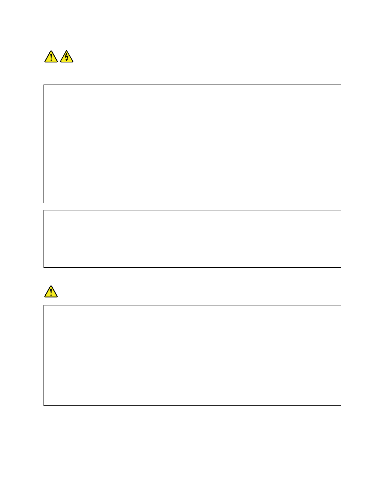
Statement1
DANGER
Electricalcurrentfrompower,telephone,andcommunicationcablesishazardous.
Toavoidashockhazard:
•Donotconnectordisconnectanycablesorperforminstallation,maintenance,orreconfigurationofthis
productduringanelectricalstorm.
•Connectallpowercordstoaproperlywiredandgroundedelectricaloutlet.
•Ensurethatallpowercordconnectorsaresecurelyandcompletelypluggedintoreceptacles.
•Connecttoproperlywiredoutletsanyequipmentthatwillbeattachedtothisproduct.
•Whenpossible,useonehandonlytoconnectordisconnectsignalcables.
•Neverturnonanyequipmentwhenthereisevidenceoffire,water,orstructuraldamage.
•Disconnecttheattachedpowercords,telecommunicationssystems,networks,andmodemsbeforeyou
openthedevicecovers,unlessinstructedotherwiseintheinstallationandconfigurationprocedures.
•Connectanddisconnectcablesasdescribedinthefollowingtablewheninstalling,moving,oropening
coversonthisproductorattacheddevices.
Toconnect:Todisconnect:
1.T urneverythingOFF.
2.First,attachallcablestodevices.
3.Attachsignalcablestoconnectors.
4.Attachpowercordstooutlets.
5.T urndevicesON.
1.T urneverythingOFF.
2.First,removepowercordsfromoutlets.
3.Removesignalcablesfromconnectors.
4.Removeallcablesfromdevices.
Statement2
DANGER
Dangerofexplosionifbatteryisincorrectlyreplaced.
Whenreplacingthelithiumcoincellbattery,useonlythesameoranequivalenttypethatis
recommendedbythemanufacturer .Thebatterycontainslithiumandcanexplodeifnotproperly
used,handled,ordisposedof.
Donot:
•Throworimmerseintowater
•Heattomorethan100°C(212°F)
•Repairordisassemble
Disposeofthebatteryasrequiredbylocalordinancesorregulations.
©CopyrightLenovo2014,2016
v
Page 8
Statement3
CAUTION:
Whenlaserproducts(suchasCD-ROMs,DVDdrives,fiberopticdevices,ortransmitters)are
installed,notethefollowing:
•Donotremovethecovers.Removingthecoversofthelaserproductcouldresultinexposureto
hazardouslaserradiation.Therearenoserviceablepartsinsidethedevice.
•Useofcontrolsoradjustmentsorperformanceofproceduresotherthanthosespecifiedherein
mightresultinhazardousradiationexposure.
DANGER
SomelaserproductscontainanembeddedClass3AorClass3Blaserdiode.Notethefollowing:
Laserradiationwhenopen.Donotstareintothebeam,donotviewdirectlywithoptical
instruments,andavoiddirectexposuretothebeam.
Statement4
≥18kg(39.7lb)≥32kg(70.5lb)≥55kg(121.2lb)
<32kg(70.5lb)<55kg(121.2lb)<100kg(220.5lb)
CAUTION:
Usesafepracticeswhenlifting.
Statement5
CAUTION:
Thepowercontrolbuttononthedeviceandthepowerswitchonthepowersupplydonotturnoff
theelectricalcurrentsuppliedtothedevice.Thedevicealsomighthavemorethanonepower
cord.T oremoveallelectricalcurrentfromthedevice,ensurethatallpowercordsaredisconnected
fromthepowersource.
viThinkServerRD450UserGuideandHardwareMaintenanceManual
Page 9
Statement6
CAUTION:
Ifyouinstallastrain-reliefbracketoptionovertheendofthepowercordthatisconnectedtothe
device,youmustconnecttheotherendofthepowercordtoapowersourcethatiseasilyaccessible
incaseitneedstobedisconnected.
Statement7
CAUTION:
Ifthedevicehasdoors,ensurethatyouremoveorsecurethedoorsbeforemovingorliftingthe
devicetoprotectagainstpersonalinjury.Thedoorswillnotsupporttheweightofthedevice.
Statement8
CAUTION:
Neverremovethecoveronapowersupplyoranypartthathasthefollowinglabelattached.
Hazardousvoltage,current,andenergylevelsarepresentinsideanycomponentthathasthislabel
attached.Therearenoserviceablepartsinsidethesecomponents.Ifyoususpectaproblemwith
oneoftheseparts,contactaservicetechnician.
Statement9
CAUTION:
Disconnectthehot-swapfancablesbeforeremovingthefanfromthedevicetoprotectagainst
personalinjury.
Statement10
CAUTION:
Thefollowinglabelindicatesasharp-edgehazard.
©CopyrightLenovo2014,2016
vii
Page 10
Statement11
CAUTION:
Thefollowinglabelindicatesapotentialheathazard.
Statement12
DANGER
Overloadingabranchcircuitisapotentialfirehazardandashockhazardundercertainconditions.T o
avoidthesehazards,ensurethatyoursystemelectricalrequirementsdonotexceedbranchcurrentratings
attheinstallationsite.
Statement13
CAUTION:
Ensurethattherackissecuredproperlytoavoidtippingwhentheserverunitisextendedontherails.
Statement14
CAUTION:
SomeaccessoryoroptionboardoutputsexceedClass2orlimitedpowersourcelimits.You
mustinstalltheappropriateinterconnectingcablinginaccordancewithyourlocalelectricalcode
requirements.
Statement15
CAUTION:
Thepower-controlbuttononthedevicemayputthedeviceinstandbymodeinsteadofturningoff
thedevice.Inaddition,thedevicemighthavemultipleconnectionstodcpower.T oremoveall
electricalcurrentfromthedevice,ensurethatallconnectionstodcpoweraredisconnectedat
thedcpowerinputterminals.
viiiThinkServerRD450UserGuideandHardwareMaintenanceManual
Page 11
Statement16
CAUTION:
Toreducetheriskofelectricshockorenergyhazards:
•Thisequipmentmustbeinstalledbytrainedservicepersonnelinarestricted-accesslocation,as
definedbyyourlocalelectricalcodeandthelatesteditionofIEC60950.
•Thebranchcircuitovercurrentprotectionmustberatedinaccordancewithlocalelectricalcode
requirements.
•Use1.3mm
2
or16AmericanWireGauge(AWG)copperconductoronly,notexceeding3meters
inlength.
•Torquethewiring-terminalscrewsto1.4newton-metersor12inch-pounds.
•Provideareadilyavailable,approvedandrateddisconnectdeviceinthefieldwiring.
Statement17
CAUTION:
ThisproductcontainsaClass1Mlaser.Donotviewdirectlywithopticalinstruments.
Statement18
CAUTION:
Donotplaceanyobjectontopofrack-mountedproducts.
Statement19
CAUTION:
Hazardousmovingparts.Keepfingersandotherbodypartsaway.
©CopyrightLenovo2014,2016
ix
Page 12

Statement20
CAUTION:
Alithiumionbatteryisprovided.T oavoidpossibleexplosion,donotburnthebattery.Replacethe
batteryonlywiththeLenovo-approvedpart.Recycleordiscardthebatteryasinstructedbylocal
regulations.
Productsthatarenotassessed
Typicalproductsthatarenotassessedincludebutnotlimitedtothefollowing:
•ServerandIT-rackcomponents(forexample,uninterruptiblepowersuppliesandcurrentdistribution
systems)
•DevicesinITrooms(forexample,bulkstorageunitsandnetworkproducts)
•Industriallow-voltageswitchgear
Safetyinspectionguide
Thepurposeofthisinspectionguideistoassistyouinidentifyingpotentiallyunsafeconditions.Aseach
machinewasdesignedandbuilt,requiredsafetyitemswereinstalledtoprotectusersandservicetechnicians
frominjury.Thisguideaddressesonlythoseitems.Youshouldusegoodjudgmenttoidentifypotentialsafety
hazardsduetoattachmentofnon-ThinkServerfeaturesoroptionsnotcoveredbythisinspectionguide.
Ifanyunsafeconditionsarepresent,youmustdeterminehowserioustheapparenthazardcouldbeand
whetheryoucancontinuewithoutfirstcorrectingtheproblem.
Considertheseconditionsandthesafetyhazardstheypresent:
•Electricalhazards,especiallyprimarypower(primaryvoltageontheframecancauseseriousorfatal
electricalshock)
•Explosivehazards,suchasadamagedCathodeRayTube(CRT)monitororabulgingcapacitor
•Mechanicalhazards,suchaslooseormissinghardware
Todeterminewhetherthereareanypotentiallyunsafeconditions,usethefollowingchecklistatthebeginning
ofeveryservicetask.Beginthecheckswiththepoweroff,andthepowercordsdisconnected.
Checklist:
1.Checkexteriorcoversfordamage(loose,broken,orsharpedges).
2.Powerofftheserver.Disconnectthepowercords.
3.Checkthepowercordfor:
a.Athird-wiregroundconnectoringoodcondition.Useametertomeasurethird-wireground
continuityfor0.1ohmorlessbetweentheexternalgroundpinandtheframeground.
b.Thepowercordshouldbetheauthorizedtypespecifiedforyourserver.Goto:
http://www.lenovo.com/serviceparts-lookup
c.Insulationmustnotbefrayedorworn.
4.Checkforcrackedorbulgingbatteries.
5.Removethecover.
6.Checkforanyobviousnon-ThinkServeralterations.Usegoodjudgmentastothesafetyofany
non-ThinkServeralterations.
xThinkServerRD450UserGuideandHardwareMaintenanceManual
Page 13

7.Checkinsidetheunitforanyobviousunsafeconditions,suchasmetalfilings,contamination,wateror
otherliquids,orsignsoffireorsmokedamage.
8.Checkforworn,frayed,orpinchedcables.
9.Checkthatthepower-supplycoverfasteners(screwsorrivets)havenotbeenremovedortamperedwith.
Groundingrequirements
Electricalgroundingoftheserverisrequiredforoperatorsafetyandcorrectsystemfunction.Proper
groundingoftheelectricaloutletcanbeverifiedbyacertifiedelectrician.
©CopyrightLenovo2014,2016
xi
Page 14

xiiThinkServerRD450UserGuideandHardwareMaintenanceManual
Page 15

Chapter1.Generalinformation
Thischapterprovidessomegeneralinformationaboutyourproduct.
Thischaptercontainsthefollowingitems:
•“Introduction”onpage1
•“Serverdocumentation”onpage2
Introduction
ThisdocumentforyourLenovo
®
ThinkServer
specifications,componentlocations,configurationinstructions,hardwarereplacementprocedures,and
basictroubleshootinganddiagnostics.
YourservercomeswiththeLenovoThinkServerDeploymentManagerprogramthatprovidesaconvenient
solutionforconfiguringtheserverandinstallinganoperatingsystem.
TheLenovoLimitedWarranty(LLW)containsthewarrantytermsthatapplytotheproductyoupurchased
fromLenovo.TheLLWisavailableathttp://www.lenovo.com/warranty/llw_02.IfyoucannotobtaintheLLW
throughtheLenovoWebsite,contactyourlocalLenovoofficeorresellertoobtainaprintedversionof
theLLW,freeofcharge.
Forwarrantyservice,consulttheworldwideLenovoSupporttelephonelist.Telephonenumbersaresubject
tochangewithoutnotice.Themostup-to-datetelephonelistforLenovoSupportisalwaysavailableonthe
Websiteathttp://www.lenovo.com/support/phone.Ifthetelephonenumberforyourcountryorregionisnot
listed,contactyourLenovoresellerorLenovomarketingrepresentative.
®
productcontainsinformationabouttheserverfeatures,
Toobtainthemostup-to-dateinformationabouttheserver,goto:
http://www.lenovo.com/thinkserver
LenovomaintainspagesontheWorldWideWeb,whereyoucangetthelatesttechnicalinformationand
downloaddocumentationordevicedriversandupdates.ToaccesstheLenovoSupportWebsite,goto:
http://www.lenovo.com/support
Recordinformationaboutyourserverinthefollowingtable.Youwillneedtheinformationifyoueverneed
tohaveyourserverserviced.
Forwheretofindtheproductinformationlabelonthechassis,see“Machinetype,model,andserialnumber
label”onpage16.
Productname
Machinetypeandmodel(MT-M)
Serialnumber(S/N)
Dateofpurchase
______________________________________________
______________________________________________
______________________________________________
______________________________________________
©CopyrightLenovo2014,2016
1
Page 16

YoucanregisteryourserverwithLenovobyfollowingtheinstructionsat:
http://www.lenovo.com/register
Whenyouregisteryourserver,informationisenteredintoadatabase,whichenablesLenovotocontact
youincaseofarecallorothersevereproblem.AfteryouregisteryourserverwithLenovo,youwillreceive
quickerservicewhenyoucallLenovoforhelp.Inaddition,somelocationsofferextendedprivilegesand
servicestoregisteredusers.
Serverdocumentation
Thistopicprovidesageneraldescriptionofeachdocumentforyourserverandinstructionsonhow
toobtainallthedocuments.
Printeddocuments
Thefollowingdocumentsareprintedoutandincludedinyourserverpackage.
•ReadMeFirst
Thisisamultilingualdocument.Itillustratessafetysymbolsandinstructsyoutoreadthecomplete
safety,warranty,andsupportinformationprovidedontheLenovoWebsitebeforeusingtheserver.This
documentalsotellsyouhowtofindthemostup-to-dateinformationontheLenovoSupportWebsite.In
addition,recycling,environmental,andlegalnoticesareallincluded.
•Alettertocustomers
Thisisamultilinguallettertocustomers,whichtellscustomersthatLenovoisundertakingapaperless
electronicdocumentationinitiativetoprotectenvironment.Thisletteralsoprovidesinformationabout
howtocontactLenovoifyourequireaprintedversionofanyelectronicdocuments.
•RackInstallationInstructions
Thisdocumentprovidesinstructionsonhowtoinstallyourserverintoastandardrackbyusingtherail
kitshippedwiththeserver.
Note:AprintedEnglishversionofthisdocumentisincludedinyourserverpackage.PDFversionsof
otherlanguagesareprovidedathttp://www.lenovo.com/support.
Electronicdocuments
•Youcanfindthefollowingelectronicdocumentsathttps://support.lenovo.com/documents/LNVO-DOCS:
–SafetyInformation
Thisisamultilingualdocumentthatincludesallthesafetystatementsforyourproduct.Ensurethatyou
readandunderstandthesesafetystatementsbeforeusingtheproduct.
–LenovoLimitedWarranty
ThisdocumentincludestheLenovotermsandwarrantystatements.
–LenovoLicenseAgreement
ThisdocumentincludesthetermsandconditionsoftheLenovoLicenseAgreement.
•YoucanfindthefollowingelectronicdocumentsattheLenovoSupportWebsite.Goto
http://www.lenovo.com/support,clickDocumentation,andfollowtheinstructionsonthescreento
findthedocumentyouneed.
–Safety,Warranty,andSupportInformation
Thisisamultilingualdocumentthatincludesallthesafetystatementsforyourproductinmorethan
30languages.Besuretoreadandunderstandallthesafetystatementsbeforeusingtheproduct.
ThisdocumentalsoincludestheLenovowarrantystatement,CustomerReplaceableUnits(CRUs)
information,andinformationabouthowtocontacttheLenovoCustomerSupportCenter.
2ThinkServerRD450UserGuideandHardwareMaintenanceManual
Page 17

–UserGuideandHardwareMaintenanceManual
Thisdocumentprovidesdetailedinformationtohelpyougetfamiliarwithyourserverandhelpyouuse,
configure,andmaintainyourserver.
–RackInstallationInstructions
Thisdocumentprovidesinstructionsonhowtoinstallyourserverintoastandardrackbyusingtherail
kitshippedwiththeserver.
–ThinkServerSystemManagerUserGuide(Englishonly)
Thisdocumentprovidesinformationaboutserverremotemanagement.
Note:Toobtainadvancedremotemanagementfunctions,installaThinkServerSystemManager
Premium(TSMPremium)moduleontheTSMPremiumconnectoronthesystemboard.See“Installing
orremovingtheThinkServerSystemManagerPremiummodule”onpage116
.
–MegaRAIDSASSoftwareUserGuide(Englishonly)
ThisdocumentprovidesinformationaboutRedundantArrayofIndependentDisks(RAID)andhowto
usetheutilityprogramstoconfigure,monitor,andmaintainyourserverRAIDandrelateddevices.
–Otherdocuments
YoumightfindotherdocumentsfortheHostBusAdapter(HBA),Ethernetcard,orotheroptionalparts.
Chapter1.Generalinformation3
Page 18

4ThinkServerRD450UserGuideandHardwareMaintenanceManual
Page 19

Chapter2.Serversetuproadmap
Thischapterprovidesageneralroadmaptoguideyouthroughsettingupyourserver.
Theserversetupprocedurevariesdependingontheconfigurationoftheserverwhenitwasdelivered.In
somecases,theserverisfullyconfiguredandyoujustneedtoconnecttheservertothenetworkandanac
powersource,andthenyoucanturnontheserver.Inothercases,theserverneedstohavehardwaredevices
installed,requireshardwareandfirmwareconfiguration,andrequiresanoperatingsystemtobeinstalled.
Thegeneralprocedureforsettingupyourserveris:
1.Unpacktheserverpackage.See“Serverpackage”onpage7.
2.Installanyrequiredhardwareorserveroptions.SeetherelatedtopicsinChapter6“Replacing
hardware”onpage63.
3.Ifnecessary,installtheserverintoastandardrackcabinetbyusingtherailkitshippedwiththeserver.
SeetheRackInstallationInstructionsthatcomeswiththeserver.
4.ConnecttheEthernetcablesandpowercordstotheserver.See“Rearviewoftheserver”onpage
24tolocatetheconnectors.
5.Turnontheservertoverifyoperation.See“Turningontheserver”onpage49.
6.ReviewtheBasicInputOutputSystem(BIOS)settingsandcustomizeasneeded.See“UsingtheSetup
Utilityprogram”onpage51.
7.ConfigureRAIDandinstalltheoperatingsystemanddevicedrivers.See“LenovoThinkServer
DeploymentManager”onpage13and“ConfiguringRAID”onpage58.
8.Installanyadditionaldriversrequiredforaddedfeatures.Refertotheinstructionsthatcomewith
thehardwareoption.
9.ConfigureEthernetsettingsintheoperatingsystembyreferringtotheoperatingsystemhelp.This
stepisnotrequirediftheoperatingsystemwasinstalledusingtheLenovoThinkServerDeployment
Managerprogram.
10.Checkforfirmwareupdates.See“Updatingthefirmware”onpage61.
11.Installmanagementapplicationsandanyotherapplications.Refertothedocumentationthatcomes
withtheapplicationsthatyouwanttoinstall.
©CopyrightLenovo2014,2016
5
Page 20

6ThinkServerRD450UserGuideandHardwareMaintenanceManual
Page 21

Chapter3.Productoverview
Thischapterprovidesinformationabouttheserverpackage,features,specifications,softwareprograms,
andcomponentlocations.
Thischaptercontainsthefollowingitems:
•“Serverpackage”onpage7
•“Features”onpage7
•“Specifications”onpage12
•“Software”onpage12
•“Locations”onpage16
Serverpackage
Theserverpackageincludesthefollowingitems:
•Server
•Railkit(availableonsomemodels)
•Cablemanagementarmorcablemanagementbar(availableonsomemodels)
•Slimopticaldrive(availableonsomemodels)
•Materialbox,includingitemssuchaspowercords(availableonsomemodels)andprinteddocumentation
Features
Thistopicprovidesgeneralinformationabouttheserverfeaturesforavarietyofmodels.Dependingonyour
specificmodel,somefeaturesmightvaryorunavailable.Forinformationaboutyourspecificmodel,usethe
SetupUtilityprogram.See“ViewinginformationintheSetupUtilityprogram”onpage51
totheProductSpecificationsReferencedocumentforThinkServerproductsat:
http://www.lenovo.com/psref/
Microprocessor
OneortwoIntel
ForalistoftheThinkServermicroprocessoroptions,goto:
http://lenovoquickpick.com/usa/home/thinkserver/rack-and-tower-server
Memory
Yourserverhas16memoryslots.Formoreinformation,see“Memorymoduleinstallationrules”onpage74.
®
®
Xeon
microprocessors(internalcachesizevariesbymodel)
.Y oualsocanrefer
©CopyrightLenovo2014,2016
7
Page 22

Powersupply
•Oneortwo450-watthot-swapredundantpowersupplies(Universalinputandcompliantwith80PLUS
Gold)
The450-watthot-swapredundantpowersuppliesarenotEnergyStar2.0compliant.Forinformation
aboutEnergyStar,see“ENERGYSTARmodelinformation”onpage204
.
•Oneortwo550-watthot-swapredundantpowersupplies(Universalinputandcompliantwith80PLUS
Platinum)
•Oneortwo750-watthot-swapredundantpowersupplies(Universalinputandcompliantwith80PLUS
Platinum)
•Oneortwo750-watthot-swapredundantpowersupplies(Highlineinputandcompliantwith80PLUS
Titanium)
•Oneortwo1100-watthot-swapredundantpowersupplies(Universalinputandcompliantwith80
PLUSPlatinum)
Note:Ifyouareusinguninterruptiblepowersupplies(UPS),ensurethatyouuseonlypure-sineUPSes
withyourThinkServerserver.
Systemfans
Yourserversupportsuptofournon-hot-swapsystemfanswithredundancy.Thisdesignhelpsyouavoid
significantcoolingproblemswhenasystemfanfails.Tolocatethesystemfans,see“Systemboard
components”onpage42.
•Ifyourserverisinstalledwithonemicroprocessor,threesystemfans(fan1tofan3)areadequateto
providepropercooling.However,youmustkeepthelocationforfan4occupiedbyadummyfanto
ensureproperairflow.
•Ifyourserverisinstalledwithtwomicroprocessors,ensurethatallthefoursystemfansareinstalledto
avoidcoolingproblems.
Internaldrives
Internaldrivesaredevicesthatyourserverusestoreadandstoredata.Theinternaldrivessupported
byyourservervarybymodel.
•Internalstoragedrive
Yourserversupportsoneofthefollowingstoragedriveconfigurations:
DrivebaysizeDrivebayquantityDrivetype
Hot-swap,SA TAorSAS
3.5-inch8
3.5-inch8
2.5-inch24
3.5-inchharddiskdriveor2.5-inchsolid-state
drive
Easy-swap,SA TAorSAS
3.5-inchharddiskdriveor2.5-inchsolid-state
drive
Hot-swap,SA TAorSAS
Harddiskdriveorsolid-statedrive
Note:Youcaninstalla2.5-inchdriveintoa3.5-inch-drivebay.Formoreinformation,see“Installinga
2.5-inchdriveintoa3.5-inch-drivebay”onpage143.
8ThinkServerRD450UserGuideandHardwareMaintenanceManual
Page 23

Notes:
–SATAistheacronymforSerialAdvancedTechnologyAttachment.
–SASstandsforSerialAttachedSCSI(SCSIistheacronymforSmallComputerSystemInterface).
–YoucaninstallSATAharddiskdrives,SASharddiskdrives,andsolid-statedrivesintothesameserver.
•Opticaldrive
–OneslimSATAopticaldriveinsomemodels
•Tapedrive
–Oneinternaltapedriveinsomemodels
Expansionslots
•Tworisercardassemblyslotsonthesystemboard
•OnePCIExpress(PCIe)slotonsystemboard
•ThreeortwoPCIeslotsontherisercard
Fordetailedinformation,see“Rearviewoftheserver”onpage24
.
Input/Output(I/O)features
•Ontherearpanel:
–Onevideographicsarray(VGA)connector
–Oneserialconnector
–TwoUSB3.0connectors
–ThreeRJ-45Ethernetconnectors
•Onthefrontpanel:
–OneVGAconnector
–TwoUSB2.0connectors
Tolocatetheconnectors,refertotherelatedtopicsin“Locations”onpage16
.
Videosubsystem
AnintegratedgraphicscontrollerisavailableinyourservertosupporttheVGAconnectorsforconnecting
videodevices.TheintegratedgraphicscontrollerislocatedintheBaseboardManagementController
(BMC)chiponthesystemboard.
•Integratedgraphicscontroller:On-boardASPEEDAST2400
•16MBofvideomemorycache
Ethernetconnectivity
TherearethreeRJ-45Ethernetconnectorsontherearpanelwith10megabitspersecond(Mbps),100
Mbps,or1000Mbpsnetworkconnectivity.OneoftheEthernetconnectorsisforsystemmanagement.To
locatetheEthernetconnectors,see“Rearviewoftheserver”onpage24
.
YoucaninstallanEthernetcardtoenablemoreEthernetconnectors.However,youmustinstalladevice
drivertoenabletheoperatingsystemtorecognizetheEthernetconnectors.Thedevicedriversareavailable
fordownloadat:
http://www.lenovo.com/drivers
Chapter3.Productoverview9
Page 24

Reliability,availability,andserviceability
Reliability,availability,andserviceability(hereinafterreferredtoasRAS)arethreeimportantserverdesign
features.TheRASfeatureshelpyouensuretheintegrityofthedatastoredontheserver,theavailabilityof
theserverwhenyouneedit,andtheeasewithwhichyoucandiagnoseandcorrectproblems.
YourserverhasthefollowingRASfeatures:
•Securityfeatures
–Administratorpasswordanduserpasswordtohelpprotectunauthorizedaccesstotheserver(see
“Usingpasswords”onpage54
)
–ThinkServerT rustedPlatformModule(TPM),whichisasecuritychip,tohelpenhanceserversecurity
Note:TheTPMisavailableonlyinsomemodels.
–Remotemonitoringorcontrolbyanadministratortoprovideprotectionorhelp
–Hot-swapredundantpowersuppliestohelpavoidsignificantinterruptiontotheoperationofthe
systemwhenapowersupplyfails
–Anintrusionswitchthatinformsyouthattheservercoverisnotproperlyinstalledorclosedbycreating
aneventinthesystemeventlog(SEL)
•Basicsystemmanagementfeatures
–Abilitytostorethepower-onself-test(POST)hardwaretestresults
–BIOSSetupUtilityprogram
TheBIOSSetupUtilityprogramhelpsyouviewtheserverinformationandconfiguretheserverinthe
pre-operatingsystemenvironment.See“UsingtheSetupUtilityprogram”onpage51
.
–TSM(alsoknownasBMC)andIntelligentPlatformManagementInterface(IPMI)2.0
ThesystemboardplatformmanagementsubsystemisbasedontheintegratedTSMfeatures.The
TSMisamanagementchipthatisintegratedonthesystemboardofyourserver.WiththeTSM,no
matterwhatconditiontheserveroperatingsystemisinandnomatteriftheserverisonoroff,aslong
astheserverisconnectedtonetworkandanacpowersource,theinteractionwiththeTSM-controlled
serverscanbeachievedthroughsystemnetwork.Theusercanobtaintheserverhardwarehealth
informationandsystemeventlog(SEL),andisabletoconducttheoperationsincludingturningonor
offtheserver,restartingtheserver,andsoon.Thispartofservermanagementisindependentofthe
operatingsystemandiscalledout-of-bandmanagement.
ThesystemboardplatformmanagementsubsystemconsistsoftheintegratedTSM,communication
buses,sensors,theBIOS,andservermanagementfirmware.Itisresponsibleforerrorreporting,
systempowercontrol,thermalmonitoring,systemfancontrol,andothermanagementfeatures.The
TSMprovidessystemmanagementandmonitoringfeaturesbasedontheIPMI2.0specification.IPMI
helpslowertheoverallcostsofservermanagement.YoucanfindmoreinformationaboutIPMI2.0
fromtheWebsiteofIntel.TheTSMalsosupportssomenon-IPMIfeatures,suchastheDynamicHost
ConfigurationProtocol(DHCP)andthePlatformEnvironmentControlInterface(PECI),toprovide
moresystemmanagementfunctions.
Youcanfindthedefaultusername,password,andotherinformationfortheTSMintheThinkServer
SystemManagerUserGuide,whichisavailablefordownloadat:
http://www.lenovo.com/UserManuals
–Hot-swapfeature
Yourserversupportshot-swapstoragedrives(includingharddiskdrivesandsolid-statedrives)and
hot-swapredundantpowersupplies.Withthehot-swapfeature,youcaninstall,remove,orreplacea
hot-swapdevicewithoutturningofftheserver.
10ThinkServerRD450UserGuideandHardwareMaintenanceManual
Page 25

–PrebootExecutionEnvironment(PXE)
TheIntelPXEtechnologyenablesyoutobootyourservers,loadanoperatingsystem,ordeploy
executableimagesfromaremoteserverbyusinganetworkinterface.Theoperationcanbedone
independentlyoflocaldatastoragedevices(suchasharddiskdrives)oroperatingsystems.
–RedundantArrayofIndependentDisks(RAID)
YourserversupportsadvancedSATA/SAShardwareRAIDifyourserverhasarequiredRAIDcardoran
AnyRAIDadapterinstalled.Fordetailedinformation,see“ConfiguringRAID”onpage58
.
–Statuslight-emittingdiodes(LEDs)anddiagnosticLEDs
FormoreinformationabouttheLEDsforyourserver,refertotherelatedtopicsin“Locations”on
page16.
–Softwareprograms
Formoreinformationaboutthesoftwareprograms,see“Software”onpage12
.
–WakeonLAN
WhentheWakeonLANfeatureisenabledonaserverthatisconnectedtoaLAN,anetwork
administratorcanremotelyturnonorwakeuptheserverfromamanagementconsoleusingremote
networkmanagementsoftware.Besides,manyotherfunctions,suchasdatatransferandsoftware
updates,canbeperformedremotelywithoutremoteattendanceandcanbedoneafternormalworking
hoursandonweekendstosavetimeandincreaseproductivity.
•Advancedsystemmanagementfeatures
TheadvancedsystemmanagementfeaturesareonlyavailablewhentheTSMdetectsthepresenceofa
TSMpremiummodule.TheTSMpremiummoduleisaremotemanagementmodule.Y oucanpurchasea
TSMpremiummodulefromLenovoandinstallitonthesystemboardtoactivatetheadvancedsystem
managementfeatures.
Formoreinformationaboutadvancedsystemmanagement,refertotheThinkServerSystemManager
UserGuide,whichisavailablefordownloadat:
http://www.lenovo.com/UserManuals
Chapter3.Productoverview11
Page 26

Specifications
Thistopicliststhephysicalspecificationsforyourserver.
Dimensions
Widthwithoutrackhandles:447mm(17.6inches)
Widthwithrackhandles:482mm(18.98inches)
Depthwithoutrackhandlesandpowersupplyhandles:764mm(29.37inches)
Depthwithrackhandlesandpowersupplyhandles:782.9mm(30.82inches)
Height:87mm(3.43inches)
Weight
Theproductweightvariesdependingondifferentsystemconfigurations.
Rangeofproductweightwithoutpackage:16kg(35.27lb)to27kg(59.52lb)
Rangeofproductweightwithpackage:21kg(46.30lb)to32kg(70.55lb)
Environment
•Airtemperature:
Operating:10°Cto35°C(50°Fto95°F)
Storage:-40°Cto70°C(-40°Fto158°F)inoriginalshippingpackage
•Altitude:0to3048m(0to10000ft)inanunpressurizedenvironment
Note:Whenthealtitudeexceeds950m(3117ft),thedefinedmaximumdry-bulbtemperatureforoperation
becomesadependentvariable.Thistemperaturevaluedecreasesby1°C(33.8°F)withevery300m(984ft)of
altitudeincrease.
•Humidity:
Operating:20%to80%(non-condensing)
Storagewithoutpackage:8%to90%(non-condensing)
Storagewithpackage:8%to90%(non-condensing)
Electricalinput
•Universalinput:
–Lowrange:
Minimum:100Vac
Maximum:127Vac
Inputfrequencyrange:50to60Hz
–Highrange:
Minimum:200Vac
Maximum:240Vac
Inputfrequencyrange:50to60Hz
Software
Thistopicprovidesinformationaboutthesoftwareprogramsthatyoucanusetosetup,use,andmaintain
theserver.
Todownloadthesoftwareprograms,gototheLenovoSupportWebsiteathttp://www.lenovo.com/support
andfollowtheinstructionsontheWebpage.
12ThinkServerRD450UserGuideandHardwareMaintenanceManual
Page 27

BIOSandTSMupdateutilities
TheBIOSandTSM(alsoknownasBMC)firmwarekeepsupdatingaftertheshipmentoftheserver.Lenovo
maintainspagesontheSupportWebsiteandprovidestheBIOSandTSMupdateutilitieswithinstructions
fordownloadtohelpyouupdatetheBIOSandTSMfirmwareifneeded.Formoreinformation,see“Updating
orrecoveringtheBIOS”onpage57
and“Updatingthefirmware”onpage61.
LenovoPartnerPackforMicrosoftSystemCenterConfigurations
Management
TheLenovoPartnerPackforMicrosoftSystemCenterConfigurationsManagement(SCCM)programhelps
youmanagethefirmwarecomponentsinyourThinkServerserver.Thefirmwarecomponentsinclude
TSM,BIOS,DeploymentManagerApplication,WindowsDriverPackageforDeploymentManager,and
LinuxDriverPackageforDeploymentManager.Theprogramalsoenablesuserstosende-mailalertsto
relatedrecipientswhencertaineventsaredetected.
Fordetailedinformationaboutusingtheprogram,refertothehelpsystemoftheprogram.
LenovoPartnerPackforMicrosoftSystemCenterOperations Management
TheLenovoPartnerPackforMicrosoftSystemCenterOperationsManagementprogramautomatically
detectsthemanagedserversofyourThinkServerserverandprovidesdetailedsysteminformationaboutthe
managedservers.Thesysteminformationincludescomponentinventory,componentstatus,andsensor
status.Theprogramalsoenablesuserstoperformmanagementtasks,suchasrestartingorturningoffyour
ThinkServerserver,launchingaremoteconsole,andaccessingtheTSMinterface.
Fordetailedinformationaboutusingtheprogram,refertothehelpsystemoftheprogram.
LenovoPartnerPackforVMwarevCenter
TheLenovoPartnerPackforVMwarevCenterprogramprovidesdetailedsysteminformationaboutthe
managedserversofyourThinkServerserverintheVMwarevirtualizedenvironment.Thesysteminformation
includestheinventoryandstatusofcomponentssuchasmicroprocessors,memorymodules,fans,and
temperaturesensors.Theprogramenablesuserstoperformtaskssuchaslaunchingaremoteconsoleand
accessingtheTSMinterface.Theprogramalsoprovidesaneasywaytoupdatethefirmwareandsend
e-mailalertstorelatedrecipientswhencertaineventsaredetected.
Fordetailedinformationaboutusingtheprogram,refertothehelpsystemoftheprogram.
LenovoThinkServerDeploymentManager
TheLenovoThinkServerDeploymentManagerprogram(hereinafterreferredtoasDeploymentManager)
simplifiestheprocessofconfiguringRAID,configuringBIOSsettings,andupdatingthefirmware.The
programworksinconjunctionwithyourWindowsorLinuxoperatingsysteminstallationdisctoautomatethe
processofinstallingtheoperatingsystemandassociateddevicedrivers.Theprogramispartoftheserver
firmware.Thehelpsystemfortheprogramcanbeaccesseddirectlyfromtheprograminterface.
DeploymentManagerhasthefollowingfeatures:
•Easy-to-use,language-selectableinterface
•Integratedhelpsystem
•Automatichardwaredetection
•Selectablepartitionsizeandfilesystemtype
Chapter3.Productoverview13
Page 28

•Abilitytoinstalltheoperatingsystemanddevicedriversinanunattendedmodetosavetime
•AbilitytocreateareusableresponsefilethatcanbeusedwithsimilarlyconfiguredLenovoserversto
makefutureinstallationsevenfaster
•ContainsRAIDconfigurationutility
•Providesdevicedriversbasedontheservermodelanddetecteddevices
•SupportsBIOSsettingsconfiguration
•Supportsfirmwareandapplicationsupdate
TouseDeploymentManager,dothefollowing:
1.Launchtheprogramthroughoneofthefollowingmethods:
•Turnontheserver.PressF10assoonasyouseethelogoscreen.Then,waitforseveralseconds.
DeploymentManageropens.
•StarttheSetupUtilityprogram.SelectBootManager➙LaunchTDM.DeploymentManageropens.
2.Readandacceptthelicenseagreement.
3.Selectthelanguageinwhichyouwanttoviewtheprogram.Then,followtheinstructionsonthe
screentousetheprogram.
BeforeinstallingaWindowsoraLinuxoperatingsystemusingDeploymentManager,itisrecommended
thatyoudothefollowing:
1.Downloadthelatestdevicedriverbundlefileforyourserver.T ofindanddownloadthebundlefile,goto
http://www.lenovo.com/driversandfollowtheinstructionsontheWebpage.
2.LaunchDeploymentManagerandclickPlatformUpdateontheleftpane.
3.SelectApplicationandthenclickNext.
4.ClickBrowsetoselectthecorrespondingbundlefileandthenclickOK.Theversioninformationis
displayed.
5.ClickFlashtoapplythebundlefileandupdatethecurrentdevicedrivers.
Note:IfyouwanttoinstallaVMwarehypervisorusingDeploymentManager,thedevicedriverbundle
fileisnotneeded.
TodownloadthelatestDeploymentManager,gotohttp://www.lenovo.com/driversandfollowthe
instructionsontheWebpage.
LenovoThinkServerDiagnostics
TheLenovoThinkServerDiagnosticsprogramenablesyoutodiagnoseserverproblems,performsome
diagnostictests,andcollectsysteminformation.Examplesofthesysteminformationincludebasic
operating-systeminformation,hardwareinformation,SEL,RAIDlog,andsoon.Dependingonthemodel,
yourservermightcomewithoneofthefollowingdiagnosticprogrameditions:
•LenovoThinkServerDiagnosticsEmbeddedEdition
•LenovoThinkServerDiagnosticsStandaloneEdition
FormoreinformationaboutLenovoThinkServerDiagnostics,goto
http://support.lenovo.com/us/en/lenovodiagnosticsolutions/downloads.LocatetheLenovoThinkServer
DiagnosticssectionatthebottomoftheWebpage.Then,clickthedesiredlinkformoreinformation.
LenovoThinkServerOperatingSystem-basedPlatformUpdateTool
TheLenovoThinkServerOperatingSystem-basedPlatformUpdateT oolisusedtoupdatethefirmwarein
theoperatingsystemforyourserver.
14ThinkServerRD450UserGuideandHardwareMaintenanceManual
Page 29

Fordetailedinformationaboutusingtheprogram,refertothehelpsystemoftheprogram.
LenovoThinkServerPowerPlanner
TheLenovoThinkServerPowerPlannerprogramprovidesinformationaboutthepowerconsumptionand
electriccurrentcalculationbasedonthedifferentconfigurationsofserversandotherdevices.Theprogram
alsohelpstoplanserversanddevicesdeploymentinanefficientway.
FordetailedinformationaboutusingtheLenovoThinkServerPowerPlannerprogram,refertothehelp
systemoftheprogram.
LenovoThinkServerSystemManager
TheLenovoThinkServerSystemManager(TSM)isamanagementsolutionthatprovidescomprehensive
andsecuremanagementfeatures.Thesefeaturesenableyoutomanageyourserversremotelyusing
aone-to-oneorone-to-manymethod.
TheTSMprovidesaone-to-oneweb-basedconsole.Theweb-basedconsoleisdevelopedinHTML5and
structuredinthewaythatmakesplatformmanagementintuitiveandefficient.TheTSMalsoprovidesa
securecommand-lineinterfaceforimprovedefficiencyandfunctionality.
FordetailedinformationaboutusingtheLenovoThinkServerSystemManagerprogram,refertothehelp
systemoftheprogram.
LenovoThinkServerSystemManagerPremium
LenovoThinkServerSystemManagerPremiumprovidesyouasolutionthatenablesyoutoreceiveallthe
benefitsandfeaturesprovidedbyboththeLenovoThinkServerSystemManagerprogramandtheLenovo
ThinkServerEnergyManagerprogram.ItalsoenablesyoutocontroltheserverremotelyusingLenovovirtual
keyboard,video,andmouse.
Fordetailedinformationaboutusingtheprogram,refertothehelpsystemoftheprogram.
LenovoXClarityAdministrator
LenovoXClarityAdministratorisacentralizedresource-managementsolutionthatenablesadministrators
todeployinfrastructurefasterandwithlesseffort.ThesolutionseamlesslyintegratesintoSystemx,
ThinkServer,andNeXtScaleservers,aswellastheFlexSystemconvergedinfrastructureplatform.
LenovoXClarityAdministratorprovidesthefollowingfeatures:
•Automateddiscoveryandinventory
•Baremetaldeployment
•Securitymanagement
•Upwardintegration
•PythonCLI,representationalstatetransfer(REST)applicationprogramminginterfaces(APIs),and
WindowsPowerShell
•Simplenetworkmanagementprotocol(SNMP),systemlog,ande-mailforwarding
FormoreinformationaboutLenovoXClarityAdministrator,goto:
http://pic.dhe.ibm.com/infocenter/flexsys/information/index.jsp?topic=%2Fcom.lenovo.lxca.doc%2
Faug_product_page.html
Chapter3.Productoverview15
Page 30

LenovoXClarityEnergyManager
TheLenovoXClarityEnergyManager(hereinafterreferredtoasEnergyManager)isatoolfordatacenter
powermanagement.Itmonitorsthepowerandtemperatureatthedevicelevelandthegrouplevel.By
monitoringandanalyzingpowerandtemperatureinformation,EnergyManagerhelpsyouincreasepower
efficiencyandimprovebusinesscontinuity.
ForinformationaboutusingLenovoXClarityEnergyManager,refertothehelpsystemoftheprogram.
LenovoToolsCenterSuiteCLI
LenovoToolsCenterSuiteCLIconsistsofindividualapplicationmodulesthatutilizeacommand-lineinterface
(CLI)tohelpyoumanageservers.Withtheinventoryapplicationmodule,LenovoToolsCenterSuiteCLI
enablesyoutogetinventoryandsysteminformationforThinkServerservers.
FormoreinformationaboutLenovoToolsCenterSuiteCLI,goto:
https://support.lenovo.com/solutions/HT116433?LinkTrack=Solr
Locations
Thistopicprovidesinformationtohelpyoulocateyourservercomponents.
Machinetype,model,andserialnumberlabel
Thistopichelpsyoutolocatethelabelthatcontainsthemachinetype,model,andserialnumberinformation
foryourserver.
WhenyoucontactLenovoforhelp,themachinetype,model,andserialnumberinformationhelpssupport
technicianstoidentifyyourserverandprovidefasterservice.
16ThinkServerRD450UserGuideandHardwareMaintenanceManual
Page 31

Thefollowingillustrationsareexamplesofthemachinetype,model,andserialnumberlabelsonserver
modelswithdifferentdrivebayconfigurations.
Note:Dependingonthemodel,yourservermightlookslightlydifferentfromtheillustrationsinthistopic.
Figure1.Labelonservermodelswith3.5-inch-drivebays
Figure2.Labelonservermodelswith2.5-inch-drivebays
Frontviewoftheserver
Thefrontviewoftheservervariesbymodel.Theillustrationsinthistopicshowtheserverfrontviews
basedonthesupportedinternaldrives:
•“Frontviewofservermodelswith3.5-inchdrives”onpage18
Chapter3.Productoverview17
Page 32

•“Frontviewofservermodelswith2.5-inchdrives”onpage19
0
1 3
2
5
4
7
6
•“Frontviewofservermodelswith2.5-inchdrivesandaslimopticaldrive”onpage20
•“Frontviewofservermodelswithaninternaltapedrive”onpage21
Note:Dependingonthemodel,yourservermightlookslightlydifferentfromtheillustrationsinthistopic.
Frontviewofservermodelswith3.5-inchdrives
Figure3.Frontviewofservermodelswith3.5-inchdrives
1Rackhandle(left)
3Pull-outinformationcard
53.5-inch-drivebays(0–7)6Rackhandle(right)
16Rackhandles
2Frontpanel
4Slimopticaldrive(availableonsomemodels)
Ifyourserverisinstalledinarackcabinet,youcanusetherackhandlestohelpyouslidetheserveroutof
therackcabinet.Y oualsocanusetherackhandlesandscrewstosecuretheserverintherackcabinetso
thattheservercannotslideout,especiallyinvibration-proneareas.Formoreinformation,refertotheRack
InstallationInstructionsthatcomeswithyourserver.
2Frontpanel
Forinformationaboutthecontrols,connectors,andstatusLEDsonthefrontpanel,see“Frontpanel”
onpage22.
3Pull-outinformationcard
Themachinetype,model,andserialnumberlabeloftheserverisattachedonthepull-outinformationcard.
See“Machinetype,model,andserialnumberlabel”onpage16.
4Slimopticaldrive
SomeservermodelscomewithaslimSATAopticaldrive(DVD-RWorDVD-ROM).
53.5-inch-drivebays(0–7)
TheEMIintegrityandcoolingoftheserverareprotectedbyhavingalldrivebayscoveredoroccupied.
Thenumberoftheinstalleddrivesinyourservervariesbymodel.Thevacantdrivebaysareoccupied
bydummytrays.
Whenyouinstalldrives,followtheorderofthedrivebaynumbers.
18ThinkServerRD450UserGuideandHardwareMaintenanceManual
Page 33

Frontviewofservermodelswith2.5-inchdrives
0
1
2
3
4
5
6
7
8
9
10
11
12
13
14
15
16
17
18
19
20
21
22
23
Figure4.Frontviewofservermodelswith2.5-inchdrives
1Rackhandle(left)
3Pull-outinformationcard
2Frontpanel
42.5-inch-drivebays(0–23)
5Rackhandle(right)
15Rackhandles
Ifyourserverisinstalledinarackcabinet,youcanusetherackhandlestohelpyouslidetheserveroutof
therackcabinet.Y oualsocanusetherackhandlesandscrewstosecuretheserverintherackcabinetso
thattheservercannotslideout,especiallyinvibration-proneareas.Formoreinformation,refertotheRack
InstallationInstructionsthatcomeswithyourserver.
2Frontpanel
Forinformationaboutthecontrols,connectors,andstatusLEDsonthefrontpanel,see“Frontpanel”
onpage22.
3Pull-outinformationcard
Themachinetype,model,andserialnumberlabeloftheserverisattachedonthepull-outinformationcard.
See“Machinetype,model,andserialnumberlabel”onpage16
42.5-inch-drivebays(0–23)
.
TheEMIintegrityandcoolingoftheserverareprotectedbyhavingalldrivebayscoveredoroccupied.
Thenumberoftheinstalleddrivesinyourservervariesbymodel.Thevacantdrivebaysareoccupied
bydummytrays.
Whenyouinstalldrives,followtheorderofthedrivebaynumbers.
Dependingonyourservermodel,allorsomeofthedrive-baygroups,suchasbays0–7,bays8–15,and
bays16–23,mightbecoveredbyEMI-protectivepanelsasawhole.
Chapter3.Productoverview19
Page 34

Frontviewofservermodelswith2.5-inchdrivesandaslimopticaldrive
0
1
2
3
4
5
6
7
8
9
10
11
12
13
14
15
Figure5.Frontviewofservermodelswith2.5-inchdrivesandaslimopticaldrive
1Rackhandle(left)
3Pull-outinformationcard
2Frontpanel
42.5-inch-drivebays(0–15)
5Slimopticaldrive(availableonsomemodels)6Rackhandle(right)
16Rackhandles
Ifyourserverisinstalledinarackcabinet,youcanusetherackhandlestohelpyouslidetheserveroutof
therackcabinet.Y oualsocanusetherackhandlesandscrewstosecuretheserverintherackcabinetso
thattheservercannotslideout,especiallyinvibration-proneareas.Formoreinformation,refertotheRack
InstallationInstructionsthatcomeswithyourserver.
2Frontpanel
Forinformationaboutthecontrols,connectors,andstatusLEDsonthefrontpanel,see“Frontpanel”
onpage22.
3Pull-outinformationcard
Themachinetype,model,andserialnumberlabeloftheserverisattachedonthepull-outinformationcard.
See“Machinetype,model,andserialnumberlabel”onpage16.
42.5-inch-drivebays(0–15)
TheEMIintegrityandcoolingoftheserverareprotectedbyhavingalldrivebayscoveredoroccupied.
Thenumberoftheinstalleddrivesinyourservervariesbymodel.Thevacantdrivebaysareoccupied
bydummytrays.
Whenyouinstalldrives,followtheorderofthedrivebaynumbers.
Iftheserversupportsuptoeightdrives,anEMI-protectivepanelcoversthebays8–15asawhole.
5Slimopticaldrive
SomeservermodelscomewithaslimSATAopticaldrive(DVD-RWorDVD-ROM).
20ThinkServerRD450UserGuideandHardwareMaintenanceManual
Page 35

Frontviewofservermodelswithaninternaltapedrive
0
1
2
3
4
5
6
7
Figure6.Frontviewofservermodelswithaninternaltapedrive
1Rackhandle(left)
3Pull-outinformationcard
5Slimopticaldrive(availableonsomemodels)6Rackhandle(right)
72.5-inch-drivebays(0–7)
16Rackhandles
2Frontpanel
4Internaltapedrive(availableonsomemodels)
Ifyourserverisinstalledinarackcabinet,youcanusetherackhandlestohelpyouslidetheserveroutof
therackcabinet.Y oualsocanusetherackhandlesandscrewstosecuretheserverintherackcabinetso
thattheservercannotslideout,especiallyinvibration-proneareas.Formoreinformation,refertotheRack
InstallationInstructionsthatcomeswithyourserver.
2Frontpanel
Forinformationaboutthecontrols,connectors,andstatusLEDsonthefrontpanel,see“Frontpanel”
onpage22.
3Pull-outinformationcard
Themachinetype,model,andserialnumberlabeloftheserverisattachedonthepull-outinformationcard.
See“Machinetype,model,andserialnumberlabel”onpage16.
4Internaltapedrive
Someservermodelscomewithaninternaltapedrive.Theinternaltapedriveenablesyoutostoredataon
tapes.
5Slimopticaldrive
SomeservermodelscomewithaslimSATAopticaldrive(DVD-RWorDVD-ROM).
72.5-inch-drivebays(0–7)
TheEMIintegrityandcoolingoftheserverareprotectedbyhavingalldrivebayscoveredoroccupied.
Thenumberoftheinstalleddrivesinyourservervariesbymodel.Thevacantdrivebaysareoccupied
bydummytrays.
Whenyouinstalldrives,followtheorderofthedrivebaynumbers.
Chapter3.Productoverview21
Page 36

Frontpanel
Thefollowingillustrationshowsthecontrols,connectors,andLEDsonthefrontpaneloftheserver.Tolocate
thefrontpanel,see“Frontviewoftheserver”onpage17.
Figure7.Frontpanel
1NetworkstatusLED
3PowerbuttonwithpowerstatusLED
5USB2.0connectors(2)6VGAconnector
1NetworkstatusLED
2SystemhealthLED
4SystemIDbuttonwithIDLED
ThenetworkstatusLEDonthefrontpanelhelpsyouidentifythenetworkconnectivityandactivity.
StatusColor
OnGreen
Blinking
Off
Theserverisconnectedtoanetwork.
Green
None
Thenetworkisconnectedandactive.
Theserverisdisconnectedfromthenetwork.
Description
22ThinkServerRD450UserGuideandHardwareMaintenanceManual
Page 37

2SystemhealthLED
ThesystemhealthLEDprovidesbasicdiagnosticfunctionsforyourserver.IfthesystemhealthLEDislit,
oneormoreLEDselsewhereintheservermightalsobelittodirectyoutothesourceoftheerror.
StatusColor
On
BlinkingAmber
Off
DescriptionAction
Thetemperatureoftheserverreachedthe
non-criticaltemperaturethreshold.
Thevoltageoftheserverreachedthe
non-criticalvoltagethreshold.
Afanhasbeendetectedtoberunningat
lowspeed.
Afanhasbeenremoved.1.Ensurethatthesystemfansare
Amber
Thepowersupplyhasacriticalerror.
Thepowercordhasbeendisconnected
fromonepowersupplyoraredundant
powersupplyhasbeenremoved.
Theserverisoverheated.
TheBMCisinitializing.
None
Theserverisoffortheserverisonandis
workingcorrectly.
ChecktheBMCforerrorsandcheckthe
systemfans.
Replacethesystemboard.
Note:Thisproceduremustbeperformed
onlybytrainedservicepersonnelofLenovo.
SeeChapter8“Gettinginformation,help,
andservice”onpage189
Checkthesystemfans.
connectedsecurelytothesystem
board.
2.Reinstalltheremovedfanorinstalla
newfantoreplacetheremovedfan.
ChecktheBMCfordetailedinformation.
1.Ensurethatthepowersuppliesare
installedsecurelyintheserver.
2.Ensurethatthepowercordsare
connectedsecurelytothepower
supplies.
3.Installanewpowersupplytoreplace
theremovedone.
ChecktheBMCforerrorsandthencheck
thesystemfans.
.
3PowerbuttonwithpowerstatusLED
Youcanpressthepowerbuttontoturnontheserverwhenyoufinishsettinguptheserver.Y oualsocan
holdthepowerbuttonforseveralsecondstoturnofftheserverifyoucannotturnofftheserverfromthe
operatingsystem.SeeChapter4“Turningonandturningofftheserver”onpage49.ThepowerstatusLED
helpsyoutodeterminethecurrentpowerstatus.
StatusColor
OnGreen
Off
Theserverison.
None
Theserverisoff.
Description
Chapter3.Productoverview23
Page 38

4SystemIDbuttonwithIDLED
WhenyoupresstheIDbuttononthefrontpanel,theIDLEDsonboththefrontandrearoftheserverare
littohelpyoulocatetheserveramongotherservers.YoualsocanturnontheIDLEDsusingaremote
managementprogramforserverpresencedetection.
StatusColor
On
Off
Blue
None
Theserverisidentified.
TheIDLEDisnotinuseortheserverisnotidentified.
Description
5FrontUSB2.0connectors(2)
UsedtoattachaUSB-compatibledevice,suchasaUSBkeyboard,mouse,scanner,orprinter.Ifyou
havemorethansixUSBdevices,youcanpurchaseaUSBhub,whichyoucanusetoconnectadditional
USBdevices.
6VGAconnector
UsedtoattachaVGA-compatiblevideodevice,suchasaVGAmonitor.
Rearviewoftheserver
Thistopicprovidesinformationtohelpyoulocatetheconnectorsandcomponentsontherearofyourserver.
Figure8.Rearviewoftheserver
1Powersupply1
3PCIeslot64PCIeslot3(onrisercardassembly2)
5PCIeslot4(onrisercardassembly2)6PCIeslot5(onrisercardassembly2)
7PCIeslot1(onrisercardassembly1)8PCIeslot2(onrisercardassembly1)
9SystemIDLED10USB3.0connectors(2)
11Ethernetconnector2(RJ-45)12Ethernetconnector1(RJ-45)
13Serialconnector14Ethernetconnectorforsystemmanagement(RJ-45)
15VGAconnector
24ThinkServerRD450UserGuideandHardwareMaintenanceManual
2Powersupply2(availableonsomemodels)
Page 39

1Powersupply1
2Powersupply2(availableonsomemodels)
Thehot-swapredundantpowersupplieshelpyouavoidsignificantinterruptiontotheoperationofthe
systemwhenapowersupplyfails.YoucanpurchaseapowersupplyoptionfromLenovoandinstallthe
powersupplytoprovidepowerredundancywithoutturningofftheserver.
Oneachpowersupply,therearethreestatusLEDsnearthepowercordconnector.Forinformationabout
thestatusLEDs,see“PowersupplystatusLEDs”onpage48.
3PCIeslotsonthesystemboard
Slot
3PCIeslot6
456PCIeslotsonrisercardassembly2
Slot
4PCIeslot3
5PCIeslot4
6PCIeslot5
78PCIeslotsonrisercardassembly1
Slot
7PCIeslot1
8PCIeslot2
PhysicallinkwidthNegotiablelinkwidth
x16x8,x4,x2,x1
PhysicallinkwidthNegotiablelinkwidth
x16x8,x4,x2,x1
x16x8,x4,x2,x1
x16x8,x4,x2,x1
PhysicallinkwidthNegotiablelinkwidth
x16x8,x4,x2,x1
x16x8,x4,x2,x1
Supportedcardlengthandheight
Low-profilecard
Supportedcardlengthandheight
Low-profilecard
Low-profilecard
Low-profilecard
Supportedcardlengthandheight
Half-length,full-heightcard
Half-length,full-heightcard
Note:Ifyourserverisinstalledwithonlyonemicroprocessor,onlyPCIeslots1and2areavailable.
9SystemIDLED
WhenyoupresstheIDbuttononthefrontpanel,theIDLEDsonboththefrontandrearoftheserverare
littohelpyoulocatetheserveramongotherservers.YoualsocanturnontheIDLEDsusingaremote
managementprogramforserverpresencedetection.
StatusColor
On
Off
10USB3.0connectors(2)
Blue
None
Theserverisidentified.
TheIDLEDisnotinuseortheserverisnotidentified.
Description
UsedtoattachadevicethatrequiresaUSB2.0or3.0connection,suchasakeyboard,amouse,ascanner,
aprinter,orapersonaldigitalassistant(PDA).
Chapter3.Productoverview25
Page 40

111214EthernetRJ-45connectors
UsedtoattachanEthernetcableforaLAN.EachEthernetconnectorhastwostatusLEDstohelpyou
identifytheEthernetconnectivity,activity,andconnectionspeed.
TheEthernetconnector0(14)markedwith“MGMT”isforsystemmanagementbydefault.Ifyouwantto
useremotemanagementfunctions,connectanEthernetcabletotheEthernetconnector0.Y oualsocan
settheEthernetconnector1forsystemmanagement.See“SettinganEthernetconnectorforsystem
management”onpage56
Figure9.EthernetstatusLEDs
.
EthernetstatusLED
1Left:dataspeed
2Right:linkandactivity
13Serialconnector
ColorStatus
Amber
GreenOn
None
GreenOn
None
Green
On
Off
Off
BlinkingTheLANisconnectedandactive.
Theconnectionspeedis1000Mbps.
Theconnectionspeedis100Mbps.
Theconnectionspeedis10Mbps.
TheserverisconnectedtoaLAN.
TheserverisdisconnectedfromaLAN.
Description
Usedtoattachadevicethatusesa9-pinserialconnector.
15VGAconnector
UsedtoattachaVGA-compatiblevideodevice,suchasaVGAmonitor.
Servercomponents
Thistopicprovidesinformationtohelpyoulocatethecomponentsofyourserver.Formoreinformation
aboutmajorcomponents,seetherelatedtopicsin“Locations”onpage16.
Toremovetheservercoverandgainaccesstotheinsideoftheserver,see“Removingtheservercover”
onpage65.
26ThinkServerRD450UserGuideandHardwareMaintenanceManual
Page 41

Thefollowingillustrationshowsthecomponentsofservermodelswithaninternaltapedriveandaslim
opticaldrive.
Note:Dependingonthemodel,yourservermightlookslightlydifferentfromtheillustrationinthistopic.
Figure10.Componentsofservermodelswithaninternaltapedriveandaslimopticaldrive
1Rackhandle(right)2Slimopticaldrive(availableonsomemodels)
3Internaltapedrive(availableonsomemodels)
5FrontVGAandUSBmodule6Rackhandle(left)
7Frontpanelboard
9Hot-swap-drivebackplane
11Systemfan12Systemboard
13CPU1DIMMs(varybymodel)
15Coin-cellbattery16Coolingshroud
17ThinkServerRAIDSuperCapacitorModule(available
42.5-inch-drivearea
8AnyRAIDadapter(availableonsomemodels)
10Systemfancage
14Heatsink
18Risercardassembly1
onsomemodels)
19Risercardassembly2
21Powersupply1
23Intrusionswitch(availableonsomemodels)24CPU2DIMMs(varybymodel)
20PCIecard(availableonsomemodels)
22Powersupply2(availableonsomemodels)
Chapter3.Productoverview27
Page 42

25CPU2DIMMs(varybymodel)26CPU1DIMMs(varybymodel)
27Servercover
CRUsarepartsthatcanbeupgradedorreplacedbythecustomer.IfaCRUisdeterminedtobedefective
duringthewarrantyperiod,areplacementCRUwillbeprovidedtothecustomer.Customersareresponsible
forinstallingtheself-serviceCRUsforthisproduct.Customersalsocaninstalloptional-serviceCRUs,which
mightrequiresometechnicalskillsortools,orrequestthatatechnicianinstalltheoptional-serviceCRU
underthetermsoftheapplicablewarrantyservicetypeforyourcountryorregion.
Non-CRUsmustbereplacedonlybytrainedservicetechnicians.
ThefollowingtableliststhemajorFRUsinyourserverandtheCRUidentificationinformation.Foracomplete
listingofFRUinformation,suchasFRUpartnumbersandsupportedservermodels,goto:
http://www.lenovo.com/serviceparts-lookup
Notes:
•BeforeservicingaLenovoproduct,ensurethatyoureadandunderstand“Readthisfirst:safety
information”onpageiii
.
•UseonlypartsprovidedbyLenovo.
*Availableonsomemodels
FRUdescription
AnyRAIDadapter*NoYes
AnyRAIDflashmodule*
Coin-cellbattery
Coolingshroud
Easy-swap-drivemodule*NoYes
Easy-swapstoragedrive*YesNo
FrontpanelboardYesNo
FrontVGAandUSBmodule
HeatsinkYesNo
Hot-swap-drivebackplane*NoYes
Hot-swapredundantpowersupplyYesNo
Hot-swapstoragedrive*YesNo
Internaltapedrive*YesNo
Intrusionswitch*YesNo
LenovoThinkServerRAID110iupgradekey*
LenovoThinkServerRAID500upgradekey*
LenovoThinkServerRAID510iupgradekey*
LenovoThinkServerRAID520iupgradekey*
LenovoThinkServerRAID720iModularDRAM
Upgrade*
LenovoThinkServerRAID720iModularFlash*
LenovoThinkServerRAIDSuperCapacitorModule*
Self-serviceCRUOptional-serviceCRU
NoYes
YesNo
YesNo
YesNo
NoYes
NoYes
NoYes
NoYes
NoYes
NoYes
NoYes
28ThinkServerRD450UserGuideandHardwareMaintenanceManual
Page 43

FRUdescription
LenovoThinkServerSystemManagerPremium
module*
LenovoThinkServerTrustedPlatformModule*
MemorymoduleYesNo
MicroprocessorNoYes
Opticaldrive*
Opticalmodule*
PCIecard*
PCIesolid-statedrive*
Powercord*YesNo
RisercardYesNo
Securedigital(SD)card*
SDmodule*
Systemboard
Systemfan
Systemfancage
Self-serviceCRUOptional-serviceCRU
YesNo
YesNo
YesNo
YesNo
YesNo
YesNo
YesNo
NoYes
NoNo
YesNo
YesNo
AnyRAIDadapterandRAIDcard
ThistopicprovidesinformationabouttheconnectorsontheAnyRAIDadapterandRAIDcard.Youcan
purchaseasupportedAnyRAIDadapterandRAIDcardfromLenovoandinstallitintotheserver.Foralistof
ThinkServeroptions,goto:
http://lenovoquickpick.com/usa/home/thinkserver/rack-and-tower-server
Note:TheoptionkitforAnyRAIDadapterorRAIDcardisdesignedfordifferenttypesofserversandmight
containadditionalcablesthatarenotrequiredforyourserver.
YouserveralsosupportstheHostBusAdapter.TheHostBusAdapterisusedtoconnectyourserverto
externalstoragedevices,suchasastoragearray.
YourserversupportsthefollowingAnyRAIDadaptersandRAIDcards:
AnyRAIDadapters(supportedtypevariesbyservermodel):
•LenovoThinkServerRAID110iAnyRAIDAdapter(alsocalledpass-throughboard)
•LenovoThinkServerRAID510iAnyRAIDAdapter
•LenovoThinkServerRAID720iAnyRAIDAdapter
•LenovoThinkServerRAID720ixAnyRAIDAdapter
RAIDcard:
•LenovoThinkServerRAID500PCIeAdapter
•LenovoThinkServerRAID520iPCIeAdapter
•LenovoThinkServerRAID710PCIeAdapter
•LenovoThinkServerRAID720iPCIeAdapter
ThefollowingillustrationshelpyoulocatetheconnectorsontheAnyRAIDadaptersandRAIDcards.
Chapter3.Productoverview29
Page 44

Note:Dependingontheconfiguration,theAnyRAIDadapterorRAIDcardinstalledinyourservermightlook
slightlydifferentfromtheillustrationsinthistopic.
LenovoThinkServerRAID110iAnyRAIDAdapter
TheLenovoThinkServerRAID110iAnyRAIDAdapterprovidesSATAsoftwareRAIDfunction.Thefollowing
illustrationshowstheconnectorsontheadapter.
Figure11.LenovoThinkServerRAID110iAnyRAIDAdapter
1SA T A0–3connector
UsedtoconnecttotheSATAconnector0(ports0–3)onthesystemboard.See“Systemboardcomponents”
onpage42.
2SA T A4–7connector
UsedtoconnecttotheSATAconnector1(ports4–7)onthesystemboard.See“Systemboardcomponents”
onpage42.
30ThinkServerRD450UserGuideandHardwareMaintenanceManual
Page 45

LenovoThinkServerRAID510iAnyRAIDAdapter
TheLenovoThinkServerRAID510iAnyRAIDAdapterprovidesadvancedSATA/SAShardwareRAID
functions.Thefollowingillustrationshowstheconnectorsontheadapter.
Figure12.LenovoThinkServerRAID510iAnyRAIDAdapter
1PCIE0connector
2PCIE1connector
UsedtoconnecttotheAnyRAIDconnector0–1onthesystemboard.See“Systemboardcomponents”
onpage42.
3RAIDupgradekeyconnector
UsedtoconnectaThinkServerRAID510iupgradekey.
Chapter3.Productoverview31
Page 46

LenovoThinkServerRAID720iAnyRAIDAdapter
TheLenovoThinkServerRAID720iAnyRAIDAdapterprovidesadvancedSATA/SAShardwareRAID
functions.Thefollowingillustrationshowstheconnectorsontheadapter.
Figure13.ThinkServerRAID720iAnyRAIDAdapter
1ThinkServerRAIDSuperCapacitorModuleconnector(availableonsomemodels)
UsedtoconnecttotheThinkServerRAIDSuperCapacitorModule.See“Servercomponents”onpage26
2PCIE0connector
3PCIE1connector
UsedtoconnecttotheAnyRAIDconnector0–1onthesystemboard.See“Systemboardcomponents”
onpage42.
.
32ThinkServerRD450UserGuideandHardwareMaintenanceManual
Page 47

ThinkServerRAID720ixAnyRAIDAdapter
TheLenovoThinkServerRAID720ixAnyRAIDAdapterprovidesadvancedSATA/SAShardwareRAID
functions.Theadapterisusedinservermodelssupportingtheinternaltapedrive.Thefollowingillustration
showstheconnectorsontheadapter.
Figure14.ThinkServerRAID720ixAnyRAIDAdapter
1SA T Aconnector
UsedtoconnecttheSATAsignalcablefromtheinternaltapedriveifoneisinstalled.
2ThinkServerRAIDSuperCapacitorModuleconnector
UsedtoconnecttotheThinkServerRAIDSuperCapacitorModule.See“Servercomponents”onpage26.
3PCIE0connector
4PCIE1connector
UsedtoconnecttotheAnyRAIDconnector0–1onthesystemboard.See“Systemboardcomponents”
onpage42.
Chapter3.Productoverview33
Page 48

LenovoThinkServerRAID500PCIeAdapter
TheLenovoThinkServerRAID500PCIeAdapterisusedtoprovideadvancedSATA/SAShardwareRAID
functions.ThefollowingillustrationshowstheconnectorsontheRAIDcard.
Figure15.LenovoThinkServerRAID500PCIeAdapter
1Connector0
UsedtoconnecttotheSASconnector1(ports0–3)onthebackplaneforuptoeight3.5-inchdrives.See
“Backplaneforuptoeight3.5-inchdrives”onpage38.
2Connector1
UsedtoconnecttotheSASconnector2(ports4–7)onthebackplaneforuptoeight3.5-inchdrives.See
“Backplaneforuptoeight3.5-inchdrives”onpage38.
3RAID500upgradekeyconnector
UsedtoconnectaLenovoThinkServerRAID500upgradekeyforadvancedRAID.
34ThinkServerRD450UserGuideandHardwareMaintenanceManual
Page 49

ThinkServerRAID520iPCIeAdapter
TheRAID520iAdapterprovidesadvancedSATA/SAShardwareRAIDfunctions.Thefollowingillustration
showstheconnectorsontheadapter.
Figure16.ThinkServerRAID520iPCIeAdapter
1Connector0
Usedtoconnectthemini-SASsignalcableconnectoronthebackplanetosupportHDD0-3.
2Connector1
Usedtoconnectthemini-SASsignalcableconnectoronthebackplanetosupportHDD4-7.
3J3connector
UsedtoconnecttoaThinkServerRAID520iupgradekey.
Chapter3.Productoverview35
Page 50

LenovoThinkServerRAID710PCIeAdapter
TheLenovoThinkServerRAID710PCIeAdapterisusedtoprovideadvancedSATA/SAShardwareRAID
functions.ThefollowingillustrationshowstheconnectorsontheRAIDcard.
Figure17.LenovoThinkServerRAID710PCIeAdapter
1Connector1
UsedtoconnecttotheSASconnector1(ports0–3)onthebackplaneforuptoeight3.5-inchdrives.See
“Backplaneforuptoeight3.5-inchdrives”onpage38
.
2Connector2
UsedtoconnecttotheSASconnector2(ports4–7)onthebackplaneforuptoeight3.5-inchdrives.See
“Backplaneforuptoeight3.5-inchdrives”onpage38.
3ThinkServerRAIDSuperCapacitorModuleconnector
UsedtoconnectthecableofaThinkServerRAIDSuperCapacitorModule.
36ThinkServerRD450UserGuideandHardwareMaintenanceManual
Page 51

ThinkServerRAID720iPCIeAdapter
TheRAID720iAdapterprovidesadvancedSATA/SAShardwareRAIDfunctions.Thefollowingillustration
showstheconnectorsontheadapter.
Figure18.ThinkServerRAID720iPCIeAdapter
1Connector0
Usedtoconnectthemini-SASsignalcableconnectoronthebackplanetosupportHDD0-3.
2Connector1
Usedtoconnectthemini-SASsignalcableconnectoronthebackplanetosupportHDD4-7.
3ThunderboltFlashModuleconnector
UsedtoconnectaThunderboltMemorymodule(hereinafterreferredtoasTMM).
Hot-swap-drivebackplane
Yourservercomeswithoneofthefollowingdrivebayandbackplaneconfigurations:
DrivebaysizeDrivebayquantityBackplanequantityDrivetype
Hot-swap,SATAorSAS
3.5-inch81
2.5-inch81
2.5-inch162
2.5-inch242
3.5-inchharddiskdriveor
2.5-inchsolid-statedrive
Hot-swap,SATAorSAS
Harddiskdriveorsolid-state
drive
Hot-swap,SATAorSAS
Harddiskdriveorsolid-state
drive
Hot-swap,SATAorSAS
Harddiskdriveorsolid-state
drive
Chapter3.Productoverview37
Page 52

Tolocatethebackplanes,see“Servercomponents”onpage26.
0 1 2 3 4 5
76
10 118 9
Backplaneforuptoeight3.5-inchdrives
Thefollowingillustrationsshowtheslotsandconnectorsonthebackplaneforuptoeight3.5-inchdrives.
Figure19.Frontviewofthebackplaneforuptoeight3.5-inchdrives
Figure20.Rearviewofthebackplaneforuptoeight3.5-inchdrives
0–7Slot0–slot7
Usedtoconnect3.5-inchdrives.
810-pinpowerconnector
Usedtoconnecttothe10-pinbackplanepowerconnectoronthesystemboardtoprovidepowertothe
backplane.
9SASconnector2(ports4–7)
Usedtoconnecttooneofthefollowingconnectors:
•SATAconnector1(ports4–7)onthesystemboard
•Port1ontheLenovoThinkServerRAID500PCIeAdapter
•Port2ontheLenovoThinkServerRAID710PCIeAdapter
102-pinpowerconnector
Usedtoconnecttoanopticaldriveifoneisinstalled.
11SASconnector1(ports0–3)
Usedtoconnecttooneofthefollowingconnectors:
•SATAconnector0(ports0–3)onthesystemboard
•Port0ontheLenovoThinkServerRAID500PCIeAdapter
•Port1ontheLenovoThinkServerRAID710PCIeAdapter
38ThinkServerRD450UserGuideandHardwareMaintenanceManual
Page 53

Backplaneforuptosixteen2.5-inchdrives
0 1 2 3 4 5 6 7 8 9 1210 11 13 14 15
16 17
Thefollowingillustrationsshowtheslotsandconnectorsonthebackplaneforuptosixteen2.5-inchdrives.
Figure21.Frontviewofthebackplaneforuptosixteen2.5-inchdrives
Figure22.Rearviewofthebackplaneforuptosixteen2.5-inchdrives
0–15Slot0–slot15
Usedtoconnect2.5-inchdrives.
1610-pinpowerconnector0
Usedtoconnecttothe10-pinbackplanepowerconnectoronthesystemboardtoprovidepowertothe
backplane.
17AnyRAIDadapterslot0
UsedtoconnectanAnyRAIDadapter.
Chapter3.Productoverview39
Page 54

Backplaneforuptoeight2.5-inchdrives(withanAnyRAID-adapterslot)
0 1 2 3 4 5 6 7
8 9
10
11
Thefollowingillustrationsshowtheslotsandconnectorsonthebackplaneforuptoeight2.5-inchdrives.
Figure23.Frontviewofthebackplaneforuptoeight2.5-inchdrives
Figure24.Rearviewofthebackplaneforuptoeight2.5-inchdrives
0–7Slot0–slot7
Usedtoconnect2.5-inchdrives.
810-pinpowerconnector0
Usedtoconnecttothe10-pinbackplanepowerconnectoronthesystemboardtoprovidepowertothe
backplane.
9AnyRAIDadapterslot0
UsedtoconnectanAnyRAIDadapter.
104-pinpowerconnector
Usedtoconnecttoaninternaltapedriveifoneisinstalled.
112-pinpowerconnector
Usedtoconnecttoaslimopticaldriveifoneisinstalled.
40ThinkServerRD450UserGuideandHardwareMaintenanceManual
Page 55

Backplaneforuptoeight2.5-inchdrives(withmini-SASconnectors)
Thefollowingillustrationsshowtheconnectorsonthebackplaneforuptoeight2.5-inchdrives(with
mini-SASconnectorsontherear).
Figure25.Frontview
Figure26.Rearview
0–7Slot0–slot7
Usedtoconnect2.5-inchhot-swapdrives.
910-pinpowerconnector
Usedtoconnectapowercabletoprovidepowertothebackplane.
810Mini-SASconnectors
Usedtoconnectthemini-SASconnectorsonaRAIDadapter.YoualsocanuseaSATAtomini-SASsignal
cabletoconnectthebackplanetotheSATAconnectorsonthesystemboard.
Chapter3.Productoverview41
Page 56

Systemboardcomponents
Thefollowingillustrationshowsthecomponentlocationsonthesystemboard.
Figure27.Systemboardcomponents
1SATAconnector(opticaldrive)2Coin-cellbattery
3SAT Aconnector1(ports4–7)4Storage-drivepowerconnector
5AnyRAIDconnector0–1
7Frontpanelconnector18Frontpanelconnector2
9SDmoduleconnector
11TSMPremiumconnector
13PCIeslot
15RAIDupgradekeyconnector16Powersupplyconnector2
17Powersupplyconnector118Intrusionswitchconnector
19Backplanepowerconnector220Backplanepowerconnector1
21Microprocessor2memoryslots(4)22Systemfan5connector
23Microprocessor2socket
25Microprocessor2memoryslots(4)26Microprocessor1memoryslots(4)
27Systemfan2connector
29Systemfan1connector30Microprocessor1memoryslots(4)
1SA T Aconnector(opticaldrive)
6SAT Aconnector0(ports0–3)
10Risercardassembly1slot
12TPMconnector
14Risercardassembly2slot
24Systemfan4connector
28Microprocessor1socket
Usedtoconnectthesignalcableoftheslimopticaldrive.
42ThinkServerRD450UserGuideandHardwareMaintenanceManual
Page 57

2Coin-cellbattery
Yourserverhasaspecialtypeofmemorythatmaintainsthedate,time,andconfigurationinformationfor
built-infeatures.Thecoin-cellbatterykeepstheinformationactivewhenyouturnofftheserver.
3SA T Aconnector1(ports4–7)
Usedtoconnecttooneofthefollowingconnectors:
•SASconnector2(ports4–7)onthebackplaneforuptoeight3.5-inchdrives
•SATA4–7connectorontheLenovoThinkServerRAID110iAnyRAIDAdapter
•SATAconnector(ports4–7)ontheeasy-swap-drivemodule
4Storage-drivepowerconnector
Usedtoconnectthe4-pinpowerconnectorontheeasy-swap-drivemodule.
5AnyRAIDconnector0–1
UsedtoconnecttothePCIeconnectorsontheAnyRAIDadapter.
6SA T Aconnector0(ports0–3)
Usedtoconnecttooneofthefollowingconnectors:
•SASconnector1(ports0–3)onthebackplaneforuptoeight3.5-inchdrives
•SATA0–3connectorontheLenovoThinkServerRAID110iAnyRAIDAdapter
•SATAconnector(ports0–3)ontheeasy-swap-drivemodule
7Frontpanelconnector1
Usedtoconnecttothefrontpanelboard.
8Frontpanelconnector2
UsedtoconnecttothefrontVGAandUSBmodule.
9SDmoduleconnector
UsedtoconnectanSDmodule.
10Risercardassembly1slot
Usedtoinstalltherisercardassembly1.
11TSMPremiumconnector
UsedtoconnectaTSMpremiummoduletoenableadvancedremotemanagementfunctionsonyourserver.
12TPMconnector
UsedtoconnectaTPM.TPMisasecuritychipthatisusedtoenhanceserversecurity.
Chapter3.Productoverview43
Page 58

13PCIeslot
UsedtoinstallasupportedPCIecard.ForinformationaboutsupportedPCIecards,see“Rearviewof
theserver”onpage24.
14Risercardassembly2slot
Usedtoinstalltherisercardassembly2.
15RAIDupgradekeyconnector
UsedtoconnectaThinkServerRAID110iupgradekey.
16Powersupplyconnector2
Usedtoconnectthepowersupply2.
17Powersupplyconnector1
Usedtoconnectthepowersupply1.
18Intrusionswitchconnector
Usedtoconnecttoanintrusionswitch.
19Backplanepowerconnector
Usedtoconnecttothe10-pinpowerconnectoronthebackplane.
20Backplanepowerconnector
Usedtoconnecttothe10-pinpowerconnectoronthebackplaneorontheeasy-swap-drivemodule.
22242729Systemfanconnector
Usedtoconnectasystemfan.
21252630Memoryslots
Thereare16memoryslotsonthesystemboard.Fordetailedinformation,see“Memorymoduleinstallation
rules”onpage74.
23Microprocessor2socket
28Microprocessor1socket
Iftheserverhastwomicroprocessors,eachofthemicroprocessorissecuredinthemicroprocessorsocket
onthesystemboardandaheatsinkisinstalledabovethemicroprocessortoprovidecooling.Iftheserver
hasonlyonemicroprocessor,themicroprocessorsocket2isprotectedbyamicroprocessorsocketcover.
44ThinkServerRD450UserGuideandHardwareMaintenanceManual
Page 59

Systemboardjumpers
Thefollowingillustrationshowsthejumpersonthesystemboardofyourserver.
Figure28.Systemboardjumpers
1Jumpercapstorage
3BIOSdefaultsettingsjumper4Clearpasswordjumper
2BIOSrecoveryjumper
Attention:Tosetthejumpers,removetheservercoverandgainaccesstothesystemboardfirst.Donot
openyourserverorattemptanyrepairbeforereadingandunderstanding“Readthisfirst:safetyinformation”
onpageiii
1Jumpercapstorage
and“Guidelines”onpage63.
Usedtostorethejumpercap.Ajumpercapisencasedonthepinsbydefault.
2BIOSrecoveryjumper
UsedtorecovertheBIOSifthepowertoyourserverisinterruptedwhiletheBIOSisbeingupdatedandyour
servercannotstartcorrectly.
TorecovertheBIOS,see“RecoveringfromaBIOSupdatefailure”onpage57.
3BIOSdefaultsettingsjumper
UsedtoturntheBIOSsettingsintothefactory-defaultsettings.
ToturntheBIOSsettingsintothefactory-defaultsettings,dothefollowing:
1.Removeallexternalmediafromthedrivesandturnoffallattacheddevicesandtheserver.Then,
disconnectallpowercordsfromelectricaloutletsanddisconnectallcablesthatareconnectedto
theserver.
2.Prepareyourserver.See“Removingorextendingtheserverfromtherackcabinet”onpage65.
Chapter3.Productoverview45
Page 60

3.Removetheservercover.See“Removingtheservercover”onpage65.
4.LocatetheBIOSdefaultsettingsjumper3onthesystemboard.Then,removeanypartsand
disconnectanycablesthatmightimpedeyouraccesstothejumper.
Note:Donotremovethememorymodulesormicroprocessors.
5.Removethejumpercapfromthejumpercapstorage1.
6.NotetheorientationofthejumpercapandtheninstallthejumpercapontheBIOSdefaultsettings
jumper.
7.Reinstallanypartsandreconnectanycables.Then,reinstalltheservercover.See“Completingthe
partsreplacement”onpage178.
8.ConnecttheservertoanacpowersourceandwaitforaboutfiveminutesfortheBMCinitialization.
Then,turnontheserver.TheBIOSsettingsturnintothefactory-defaultsettings.
9.Repeatstep1throughstep3.
10.Movethejumpercapbacktothejumpercapstorage1.
11.Reinstallanypartsandreconnectanycables.Then,reinstalltheservercover.See“Completingthe
partsreplacement”onpage178.
12.Connecttheservertoanacpowersourceandturnontheserver.
4Clearpasswordjumper
Usedtoeraseforgottenpasswords,suchastheBIOSpasswords.
Toclearpasswords,dothefollowing:
1.Removeallexternalmediafromthedrivesandturnoffallattacheddevicesandtheserver.Then,
disconnectallpowercordsfromelectricaloutletsanddisconnectallcablesthatareconnectedto
theserver.
2.Prepareyourserver.See“Removingorextendingtheserverfromtherackcabinet”onpage65.
3.Removetheservercover.See“Removingtheservercover”onpage65.
4.Locatetheclearpasswordjumper4onthesystemboard.Then,removeanypartsanddisconnectany
cablesthatmightimpedeyouraccesstothejumper.
Note:Donotremovethememorymodulesormicroprocessors.
5.Removethejumpercapfromthejumpercapstorage1.
6.Notetheorientationofthejumpercapandtheninstallthejumpercapontheclearpasswordjumper.
7.Reinstallanypartsandreconnectanycables.Then,reinstalltheservercover.See“Completingthe
partsreplacement”onpage178
.
8.ConnecttheservertoanacpowersourceandwaitforaboutfiveminutesfortheBMCinitialization.
Then,turnontheserver.TheBIOSpasswordsareerased,includingtheadministratorpasswordand
userpassword.
9.Repeatstep1throughstep3.
10.Movethejumpercapbacktothejumpercapstorage1.
11.Reinstallanypartsandreconnectanycables.Then,reinstalltheservercover.See“Completingthe
partsreplacement”onpage178.
12.Connecttheservertoanacpowersourceandturnontheserver.
13.Tosetnewpasswords,see“Usingpasswords”onpage54.
46ThinkServerRD450UserGuideandHardwareMaintenanceManual
Page 61

Hot-swap-driveactivityandstatusLEDs
12
Eachhot-swapdrivehastwoLEDsonthefront.
Figure29.Hot-swap-driveactivityandstatusLEDs
1DriveactivityLED2DrivestatusLEDDescription
OffOff
On,greenOff
Blinking,green
On,greenBlinkingrapidly(about
On,greenOn,amberOneofthefollowingsituations:
Off
fourflashesper
second),amber
Thedrivehasfailedorisnotpresent.
Thedriveispresentbutnotinuse.
Thedriveisactiveanddataisbeingtransferred.
TheRAIDcontrollerisidentifyingthedrive.
•Thedrivehasfailed.Replacethedrive.
•ThestatusofthedriveisUnconfiguredBad.Replacethedrive.
Blinking,green
Blinkingslowly(about
oneflashpersecond),
amber
Note:IfadriveinaRAIDarrayisremovedandthenreinstalled
whiletheserverison,thestatusofthedrivewillbeidentifiedas
UnconfiguredBad.Inthiscase,donotreplacethedrive.You
canchangethedrivestatusintoUnconfiguredGoodusingthe
ThinkServerMegaRAIDSASSoftware.
•ThestatusofthedriveisOffline.Y oucanchangethedrivestatus
intoOnlineusingtheThinkServerMegaRAIDSASSoftware.
FordetailedinformationaboutusingtheThinkServerMegaRAID
SASSoftware,refertotheThinkServerMegaRAIDSASSoftware
UserGuide.Youcanobtainthemostup-to-datedocumentationfor
yourserverfromtheLenovoWebsiteat:
http://www.lenovo.com/UserManuals
Thedriveisbeingrebuilt.
Chapter3.Productoverview47
Page 62

PowersupplystatusLEDs
1
2
3
Eachhot-swappowersupplyhasthreestatusLEDs.
Figure30.PowersupplystatusLEDs
LED
1InputstatusLED
2Outputstatus
LED
Status
Off
On,green
Off
Blinking,green(aboutone
flasheverytwoseconds)
Blinking,green(abouttwo
flasheseachsecond)
On,green
Off
On,amber
DescriptionAction
Thepowersupplyis
disconnectedfromtheac
powersource.
Thepowersupplyisconnected
totheacpowersource.
Theserverisofforthepower
supplyisnotworkingnormally.
Thepowersupplyisincold
redundancyactivemode.
Thepowersupplyisincold
redundancysleepmode.
Theserverisonandthepower
supplyisworkingnormally.
Thepowersupplyisworking
normally.
Thepowersupplyhasfailed.
Noactionisneeded.
Noactionisneeded.
Replacethepowersupply.
See“Installingorreplacinga
hot-swapredundantpower
supply”onpage121
Noactionisneeded.
Noactionisneeded.
Noactionisneeded.
Noactionisneeded. 3FaultLED
Replacethepowersupply.
See“Installingorreplacinga
hot-swapredundantpower
supply”onpage121
.
.
Connectingcables
Toconnectthesignalcablesfromtheinstalledhardwarecomponents,refertotherelatedinformation
inthefollowingtopics:
•“Systemboardcomponents”onpage42
•“AnyRAIDadapterandRAIDcard”onpage29
•“Hot-swap-drivebackplane”onpage37
•“Installingthetapedrive”onpage166
48ThinkServerRD450UserGuideandHardwareMaintenanceManual
Page 63

Chapter4.Turningonandturningofftheserver
Thischapterprovidesinformationaboutturningonandturningofftheserver.
Turningontheserver
Theservercanbeturnedoninoneofthefollowingways:
•Afteryoufinishunpackingandsettinguptheserver,connectittoanacpowersource.Pressthepower
buttononthefrontpaneltoturnontheserver.See“Frontpanel”onpage22
30secondsfortheThinkServerSystemManager(TSM,alsoknownasBMC)toinitializewheneveryou
connecttheservertoanacpowersource.Ifyoupressthepowerbuttononthefrontpanelduringthis
period,theserverwillnotstartimmediately;itwillstartaftertheTSMinitializationfinishes.
•WhentheWakeonLANfeatureisenabledontheserverthatisconnectedtoanacpowersourceanda
LAN,anetworkadministratorcanremotelyturnonorwakeuptheserverfromamanagementconsole
usingremotenetworkmanagementsoftware.
•YoualsocanusetherelatedTSMfeaturetoremotelyturnontheserverthroughthemanagementLAN.
Turningofftheserver
CAUTION:
Thepowercontrolbuttononthedeviceandthepowerbuttononthepowersupplydonotturnoff
theelectricalcurrentsuppliedtothedevice.Thedevicealsomighthavemorethanonepower
cord.T oremoveallelectricalcurrentfromthedevice,ensurethatallpowercordsaredisconnected
fromthepowersource.
.Theserverneedsabout
Theservercanbeturnedoffinoneofthefollowingways:
•Turnofftheserverfromtheoperatingsystemifyouroperatingsystemsupportsthisfeature.Afteran
orderlyshutdownoftheoperatingsystem,theserverwillturnoffautomatically.Forinstructionsonhow
toshutdownyourspecificoperatingsystem,refertotherelateddocumentationorhelpsystemfor
theoperatingsystem.
•Pressthepowerbuttononthefrontpaneltostartanorderlyshutdownoftheoperatingsystemandturn
offtheserver,ifyouroperatingsystemsupportsthisfeature.
•Ifyourserverstopsrespondingandyoucannotturnitoff,pressandholdthepowerbuttononthe
frontpanelforfoursecondsormore.Ifyoustillcannotturnofftheserver,disconnectallpowercords
fromtheserver.
•IftheserverisconnectedtoaLAN,anetworkadministratorcanremotelyturnofftheserverfroma
managementconsoleusingremotenetworkmanagementsoftware.
•YoualsocanusetherelatedTSMfeaturetoremotelyturnofftheserverthroughthemanagementLAN.
•Theservermightbeturnedoffasanautomaticresponsetoacriticalsystemfailure.
Notes:
•Whenyouturnofftheserverandleaveitconnectedtoanacpowersource,theserveralsocanrespond
toaremoterequesttoturnontheserver.Toremoveallpowerfromtheserver,youmustdisconnect
theserverfromtheacpowersource.
©CopyrightLenovo2014,2016
49
Page 64

•Forinformationaboutyourspecificoperatingsystem,refertotherelateddocumentationorhelpsystem
fortheoperatingsystem.
50ThinkServerRD450UserGuideandHardwareMaintenanceManual
Page 65

Chapter5.Configuringtheserver
Thischapterprovidesthefollowinginformationtohelpyouconfiguretheserver:
•“UsingtheSetupUtilityprogram”onpage51
•“ConfiguringRAID”onpage58
•“Updatingthefirmware”onpage61
UsingtheSetupUtilityprogram
TheSetupUtilityprogramispartoftheserverfirmware.YoucanusetheSetupUtilityprogramtoviewand
changetheconfigurationsettingsofyourserver,regardlessofwhichoperatingsystemyouareusing.
However,theoperatingsystemsettingsmightoverrideanysimilarsettingsintheSetupUtilityprogram.
StartingtheSetupUtilityprogram
TostarttheSetupUtilityprogram,dothefollowing:
1.Connecttheservertoanacpowersourceandpressthepowerbuttononthefrontpaneltoturnonthe
server.See“Turningontheserver”onpage49
2.PresstheF1keyassoonasyouseethelogoscreen.Then,waitforseveralseconds,andtheSetup
Utilityprogramopens.Ifyouhavesetapassword,typethecorrectpasswordtoentertheSetupUtility
program.Forpasswordinformation,see“Usingpasswords”onpage54
.
.
ViewinginformationintheSetupUtilityprogram
TheSetupUtilityprogrammenulistsvariousitemsaboutthesystemconfiguration.Selectadesireditem
toviewinformationorchangesettings.
WhenworkingwiththeSetupUtilityprogram,youmustusethekeyboard.Thekeysusedtoperformvarious
tasksaredisplayedontherightbottompaneofeachscreen.Y oualsocanpresstheF1keyforgeneralhelp
aboutthekeys.Formostitems,thecorrespondinghelpmessageisdisplayedontherighttoppaneofthe
screenwhentheitemisselected.Iftheitemhassubmenus,youcandisplaythesubmenusbypressingEnter.
SetupUtilityprograminterface
DependingontheBIOSversionofyourserver,somemenuoriteminformationmightdifferslightlyfrom
theinformationinthistopic.
Notes:
•Thedefaultsettingsalreadyareoptimizedforyou.Usethedefaultvalueforanyitemyouarenotfamiliar
with.Donotchangethevalueofunfamiliaritemstoavoidunexpectedproblems.Ifyouconsider
changingtheserverconfiguration,proceedwithextremecaution.Settingtheconfigurationincorrectly
mightcauseunexpectedresults.IfyoucannotturnontheserverbecauseofincorrectBIOSsettings,
usetheBIOSdefaultsettingsjumpertorestoretheBIOSsettingstothefactorydefaultsettings.See
“Systemboardjumpers”onpage45
•Ifyouhavechangedanyhardwareintheserver,upgradetheBIOSandtheTSMfirmwareifnecessary.
.
©CopyrightLenovo2014,2016
51
Page 66

TheSetupUtilityprogrammaininterfaceconsistsofthefollowingmenus:
•“SystemInformationmenu”onpage52
•“AdvancedSettingsmenu”onpage52
•“SystemSecuritymenu”onpage53
•“TSMSettingsmenu”onpage53
•“BootManagermenu”onpage53
•“Save&Exitmenu”onpage53
LenovoprovidestheBIOSupdateutilityontheLenovoSupportWebsite.YoucandownloadtheBIOS
updateutilitytoupdatetheBIOS.See“UpdatingorrecoveringtheBIOS”onpage57
IfthepowertoyourserverisinterruptedwhiletheBIOSisbeingupdatedandyourservercannotstart
correctly,theBIOSwillrecovertothepreviousversionautomatically.Therecoveryprocesslastsabout20
minutes.YoualsocanusetheBIOSrecoveryjumpertorecoverfromaBIOSupdatefailure.See“System
boardjumpers”onpage45.
.
SystemInformationmenu
AfterenteringtheSetupUtilityprogram,youcanseetheSystemInformationmenu.Themenulistsbasic
informationaboutyourserver,suchastheBIOS,microprocessortype,memory,andsystemdateandtime.
TosetthesystemdateandtimeontheSystemInformationmenu,see“Settingthesystemdateand
time”onpage54
.
AdvancedSettingsmenu
YoucanvieworchangevariousservercomponentsettingsontheAdvancedSettingsmenuintheSetup
Utilityprogram.TheAdvancedSettingsmenucontainsvariousconfigurationsubmenusanditems.On
eachsubmenu,pressEntertoshowselectableoptionsandselectadesiredoptionbyusingtheupand
downarrowkeysortypedesiredvaluesfromthekeyboard.Someitemsaredisplayedonthemenuonlyif
theserversupportsthecorrespondingfeatures.
Notes:
•Enabledmeansthatthefunctionisconfigured.
•Disabledmeansthatthefunctionisnotconfigured.
TheAdvancedSettingsmenucontainsthefollowingsubmenus.Formoreinformation,enterthe
correspondingsubmenuandrefertotheinstructionsonthescreen.
•ProcessorSettings:Viewinformationabouttheinstalledmicroprocessorsandsetmicroprocessor
configurationparameters.
•MemorySettings:Viewinformationabouttheinstalledmemorymodulesandsetmemoryconfiguration
parameters.
•AdvancedPowerSettings:Viewandsetpowerandperformanceparameters.
•PCI/PCIESettings:ViewandsetPCIorPCIeconfigurationparameters.
•SATASettings:SetonboardSATAparameters.
•USBSettings:ViewandsetUSBconfigurationparameters,suchasenablingordisablingUSBdevices.
•SerialSettings:Viewandsetconfigurationparametersfortheserialconnector.
•WakeupSettings:Viewandconfigurethewakeuptimingandsetthepowerstateafterapowerfailure.
•MiscellaneousSettings:Viewandconfiguresomemiscellaneousitems,suchastheNumLockkeyon
thekeyboardandthebootstatuscode.
52ThinkServerRD450UserGuideandHardwareMaintenanceManual
Page 67

SystemSecuritymenu
YoucansetpasswordsandconfiguretheTPMfunctionontheSystemSecuritymenuintheSetupUtility
program.Foreachmenuitem,pressEntertoshowselectableoptionsandselectadesiredoptionbyusing
theupanddownarrowkeysortypedesiredvaluesfromthekeyboard.Someitemsaredisplayedonthe
menuonlyiftheserversupportsthecorrespondingfeatures.
Notes:
•Enabledmeansthatthefunctionisconfigured.
•Disabledmeansthatthefunctionisnotconfigured.
TheSystemSecuritymenucontainsthefollowingitems:
•AdministratorPassword:Setanadministratorpasswordtoprotectagainstunauthorizedaccessto
yourserver.See“Usingpasswords”onpage54
•UserPassword:Setauserpasswordtoprotectagainstunauthorizedaccesstoyourserver.See“Using
passwords”onpage54.
•SecureBoot:Setsecurebootparameters.
•TPM/TCM:ConfiguretheTPMfunctionifyourserverhasaTPMinstalledintheTPMconnectoronthe
systemboard.See“ConfiguringtheTPMfunction”onpage56.
.
TSMSettingsmenu
YoucanvieworchangeeventlogandBMCsettingsontheTSMSettingsmenuintheSetupUtilityprogram.
Oneachsubmenu,pressEntertoviewtheinformationorshowselectableoptionsandselectadesired
optionbyusingtheupanddownarrowkeys.Someitemsaredisplayedonthemenuonlyiftheserver
supportsthecorrespondingfeatures.
TheTSMSettingsmenucontainsthefollowingsubmenus.Formoreinformation,enterthecorresponding
submenuandrefertotheinstructionsonthescreen.
•TSMNetworkSettings:SetBMCmanagementnetworkconfigurationparameters.
•UserAccountSettings:SetBMCuseraccountparameters.
BootManagermenu
TheBootManagermenuintheSetupUtilityprogramlistsallthebootabledevicesinstalledinyourserver
andthelisteditemsvarydependingonyourserverconfiguration.
TheBootSequencesubmenuintheBootManagermenuprovidesaninterfacetohelpyouvieworchange
theserverstartupoptions,includingthestartupsequenceandbootpriorityforvariousdevices.Changesin
thestartupoptionstakeeffectwhentheserverrestarts.Thestartupsequencespecifiestheorderinwhich
theserverchecksdevicestofindabootrecord.Theserverstartsfromthefirstbootrecordthatitfinds.For
example,youcandefineastartupsequencethatchecksadiscintheopticaldrive,thencheckstheinternal
storagedrive,andthenchecksanetworkdevice.Forinformationaboutsettingthestartupsequenceor
selectingastartupdevice,see“Selectingastartupdevice”onpage55
.
Save&Exitmenu
AfteryoufinishviewingorchangingsettingsintheSetupUtilityprogram,youcanchooseadesired
actionfromtheSave&Exitmenutosavechanges,discardchanges,orloaddefaultvalues,andexitthe
program.PressEntertoselecttheitemontheSave&Exitmenu,andthenselectY eswhenpromptedto
confirmtheaction.ForinformationaboutexitingtheSetupUtilityprogram,see“ExitingtheSetupUtility
program”onpage56
.
TheSave&Exitmenucontainsthefollowingitems:
Chapter5.Configuringtheserver53
Page 68

•SaveChangesandReset:SavechangesandthencontinuewithfurtherconfigurationintheSetup
Utilityprogram.
•DiscardChangesandExit:Discardchanges,loadpreviousvalues,andthenexittheSetupUtility
program.
•LoadOptimizedDefaults:Returntotheoptimizeddefaultsettings.
•SaveasUserDefaults:Savethecurrentsettingsasuserdefaultvalues.
•RestoreUserDefaults:Restoretheuserdefaultvaluesforalltheitems.
•PureUEFIOSOptimizedDefaults:EnableordisableoptimizeddefaultsettingsforthepureUEFI
operatingsystem.
Settingthesystemdateandtime
TosetthesystemdateandtimeintheSetupUtilityprogram,dothefollowing:
1.StarttheSetupUtilityprogram.See“StartingtheSetupUtilityprogram”onpage51.
2.OntheSystemInformationmenu,selectSystemDateorSystemTime.
3.UsetheTabkeytoswitchbetweendataelementsandtypethenumbersfromthekeyboardtosetthe
systemdateandtime.
4.PressF10tosavesettingsandexittheSetupUtilityprogram.
Usingpasswords
ByusingtheSetupUtilityprogram,youcansetapasswordtopreventunauthorizedaccesstoyourserver.
Youdonothavetosetapasswordtouseyourserver.However,usingapasswordimprovescomputing
security.Ifyoudecidetosetapassword,readthefollowingtopics.
SetupUtilityprogrampasswordtypes
ThefollowingtypesofpasswordsareavailableintheSetupUtilityprogram:
•Administratorpassword
Settinganadministratorpassworddetersunauthorizedusersfromchangingconfigurationsettings.If
youareresponsibleformaintainingtheconfigurationsettingsofseveralservers,youmightwanttoset
anadministratorpassword.Whenanadministratorpasswordisset,youarepromptedtotypeavalid
passwordeachtimeyoutrytoaccesstheSetupUtilityprogram.TheSetupUtilityprogramcannot
beaccesseduntilavalidpasswordistypedin.
•Userpassword
Whenauserpasswordisset,youarepromptedtotypeavalidpasswordeachtimetheserverturnson.
Youcannotlogintoanyoperatingsystemuntilavalidpasswordistypedin.
Note:Ifboththeadministratorpasswordanduserpasswordareset,youcantypeeitherpasswordtouse
theserver.However,youmustuseyouradministratorpasswordtochangeanyconfigurationsettings.
Passwordconsiderations
Forsecurityreasons,itisrecommendedtouseastrongpasswordthatcannotbeeasilycompromised.
Notes:
•TheSetupUtilityprogrampasswordsarenotcasesensitive.
•TheserversupportsSetupUtilityprogrampasswordsthatconsistofthreeto32characters.
Tosetastrongpassword,usethefollowingguidelines:
54ThinkServerRD450UserGuideandHardwareMaintenanceManual
Page 69

•Haveatleasteightcharactersinlength
•Containatleastonealphabeticcharacterandonenumericcharacter
•Notbeyournameoryourusername
•Notbeacommonwordoracommonname
•Besignificantlydifferentfromyourpreviouspasswords
Besidesthealphabeticcharacters(a–z)andnumericcharacters(0–9),theserveralsosupportscharacters
typedusingspecialkeysonthekeyboardforapassword.Refertothehelpmessageonthescreenwhen
settingapasswordtodeterminethevalidspecialcharacters.
Setting,changing,ordeletingapassword
Thistopicprovidesinstructionsonhowtoset,change,ordeleteapasswordintheSetupUtilityprogram.
Toset,change,ordeleteapasswordintheSetupUtilityprogram,dothefollowing:
1.StarttheSetupUtilityprogram.See“StartingtheSetupUtilityprogram”onpage51.
2.OntheSystemSecuritymenu,selectAdministratorPasswordtosetanadministratorpasswordor
selectUserPasswordtosetauserpassword.
3.See“Passwordconsiderations”onpage54.Then,followtheinstructionsonthescreentosetor
changeapassword.
4.Ifyouwanttodeleteapassword,typeyourcurrentpassword.PressEnterwhenyouareprompted
totypeanewpassword.Then,pressEntertoconfirmthenewpassword.Thepreviouspassword
willbecleared.
Note:Forsecurityreasons,itisrecommendedthatyoualwayssetapasswordforyourserver.
5.PressF10tosavesettingsandexittheSetupUtilityprogram.
Ifyouhaveforgottenthepassword,youcanusetheclearpasswordjumperonthesystemboardtoerase
thepassword.See“Systemboardjumpers”onpage45.Then,setanewpasswordfortheserver.
Selectingastartupdevice
Ifyourserverdoesnotstartupfromadesireddevicesuchasthediscorharddiskdriveasexpected,doone
ofthefollowingtoselectthestartupdeviceyouwant.
Note:Notalldiscs,harddiskdrives,orotherremovabledevicesarebootable.
•Toselectatemporarystartupdevice,dothefollowing:
Note:Selectingastartupdeviceusingthefollowingmethoddoesnotpermanentlychangethestartup
sequence.
1.Turnonorrestartyourserver.
2.Whenyouseethelogoscreen,pressF11ifyourserverisconnectedtoanetworkandyouwantto
startuptheserverfromthenetwork.Otherwise,pressF12todisplaythebootmenu.Theboot
deviceselectionwindowopens.
3.Inthebootdeviceselectionwindow,usetheupanddownarrowkeysonthekeyboardtoswitch
betweentheselections.PressEntertoselectthedeviceofyourchoice.Then,theserverwillstart
upfromtheselecteddevice.
•Tovieworpermanentlychangetheconfiguredstartupdevicesequence,dothefollowing:
1.StarttheSetupUtilityprogram.See“StartingtheSetupUtilityprogram”onpage51.
Chapter5.Configuringtheserver55
Page 70

2.OntheBootSequencesubmenuundertheBootManagermenu,followtheinstructionsonthe
screentosetthestartupdeviceforBootOption#1toBootOption#5dependingonyourneeds.
Youalsocansetthebootpriorityforvariousdevices.See“BootManagermenu”onpage53
3.PressF10tosavesettingsandexittheSetupUtilityprogram.Theserverwillfollowthestartupdevice
sequenceyouhaveseteachtimeyouturnontheserver.
ConfiguringtheTPMfunction
TheTPMworksasahardwaresecuritysolutiontohelpyouencryptdataandprotecttheserver.The
TPMfunctionisonlyavailablewhenthereisaTPMinstalledinyourserver.See“InstallingtheTPM”on
page119.YoucanpurchaseaTPMfromLenovo.
AfterinstallingaTPM,checkiftheTPMfunctionisenabledintheSetupUtilityprogram.
ToenabletheTPMfunctionintheSetupUtilityprogram,dothefollowing:
1.StarttheSetupUtilityprogram.See“StartingtheSetupUtilityprogram”onpage51.
2.OntheSystemSecuritymenu,selectTPMSettings➙TPMSupport.
3.Dooneofthefollowing:
•IfTPMSupportissettoEnabled,theTPMSecurityFeatureitemisdisplayed.SetTPMSecurity
FeaturetoActivate.
•IfTPMSupportissettoDisabled,dothefollowing:
a.SetTPMSupporttoEnabledandpressF10tosavesettingsandexittheSetupUtilityprogram.
Theserverwillrestart.
b.StarttheSetupUtilityprogram.OntheSystemSecuritymenu,selectTPMSettings.Then,set
TPMSecurityFeaturetoActivate.
4.PressF10tosavesettingsandexittheSetupUtilityprogram.Theserverwillrestarttoenablethe
TPMfunction.
.
SettinganEthernetconnectorforsystemmanagement
TherearethreeRJ-45Ethernetconnectorsontherearoftheserver.Ethernetconnector0isforsystem
managementbydefault.However,youalsocansetEthernetconnector1forsystemmanagementuse.
Whenusedforsystemmanagement,Ethernetconnector1andEthernetconnector0cannotbeteamed
orsetforfailover.Onlyoneofthemcanbeusedatatime.T olocatethethreeEthernetconnectors,see
“Rearviewoftheserver”onpage24
TosettheEthernetconnectorforsystemmanagement,dothefollowing:
1.StarttheSetupUtilityprogram.See“StartingtheSetupUtilityprogram”onpage51.
2.OntheTSMSettingsmenu,selectTSMNetworkSettings➙TSMNICSelection.
3.Dooneofthefollowing:
•TosettheEthernetconnector0forsystemmanagement,selectDedicatedPort.
•TosettheEthernetconnector1forsystemmanagement,selectSharedNICPort.
4.PressF10tosavesettingsandexittheSetupUtilityprogram.
.
ExitingtheSetupUtilityprogram
Afteryoufinishviewingorchangingsettings,pressEsctoreturntotheSetupUtilityprogrammaininterface.
Ifyouareonanestedsubmenu,pressEscrepeatedlyuntilyoureachthemaininterface.Then,youcando
oneofthefollowingtoexittheSetupUtilityprogram:
56ThinkServerRD450UserGuideandHardwareMaintenanceManual
Page 71

•IfyouwanttosavethenewsettingsandexittheSetupUtilityprogram,pressF10orselectSave&Exit➙
SaveChangesandReset.Otherwise,yourchangeswillnotbesaved.
•Ifyoudonotwanttosavethenewsettings,selectSave&Exit➙DiscardChangesandExit.
•Ifyouwanttoreturntothedefaultsettings,pressF9orselectSave&Exit➙LoadOptimizedDefaults.
FormoreinformationabouttheSave&ExitmenuintheSetupUtilityprogram,see“Save&Exitmenu”
onpage53.
UpdatingorrecoveringtheBIOS
ThistopicprovidesinstructionsonhowtoupdatetheBIOSandhowtorecoverfromaPOSTandBIOS
updatefailure.
LenovomightmakechangesandenhancementstotheBIOSandTSMfirmware.Whenupdatesarereleased,
theyareavailablefordownloadontheLenovoWebsiteathttp://www.lenovo.com/drivers.Youcanupdate
theserverfirmwarebydownloadinganupdatepackageandfollowingtheinstructionsontheWebpage.
Updating(flashing)theBIOS
Thistopicprovidesinstructionsonhowtoupdate(flash)theBIOS.
Notes:
•UpdatetheBIOSonyourserveronlyifthenewerBIOSversionspecificallysolvesaproblemyouhave.
WedonotrecommendBIOSupdatesforserversthatdonotneedthem.Youcanviewtheupdated
informationforthenewBIOSversionintheinstallationinstructionsfortheBIOSupdateutilityprogram.
•DowngradingtheBIOStoanearlierversionisnotrecommendedandmightnotbesupported.Anearlier
BIOSversionmightnotsupportthelatestsystemconfigurations.
•IfthepowertoyourserverisinterruptedwhilethePOSTandBIOSarebeingupdated,yourservermight
notrestartcorrectly.EnsurethatyouperformtheBIOSupdateprocedureinanenvironmentwitha
steadypowersupply.Besides,ensurethatyourservercanrestartsuccessfullywithoutencountering
hardwareproblems.
•AfterupdatingtheBIOSfirmware,allofyourpreviousBIOSsettingswillbeautomaticallyrestored.Check
andreconfiguretheBIOSsettingsforyourspecificneeds.
Toupdate(flash)theBIOS,dothefollowing:
1.Gotohttp://www.lenovo.com/driversandfollowtheinstructionsontheWebpagetolocatetheBIOS
updatepackage.
2.DownloadtheBIOSupdatepackageandtheinstallationinstructionsinaTXTfile.
3.PrinttheTXTfilethatcontainstheinstallationinstructionsandfollowtheinstructionstoupdate(flash)
theBIOS.
4.CheckandreconfiguretheBIOSsettingsforyourspecificneedsbasedonyournoteorreferto“Using
theSetupUtilityprogram”onpage51
aftertheBIOSupdateprocessiscompleted.
RecoveringfromaBIOSupdatefailure
IfthepowertoyourserverisinterruptedwhiletheBIOSisbeingupdated,yourservermightnotrestart
correctly.PerformthefollowingproceduretorecoverfromtheBIOSupdatefailure.
Note:IftheoperatingsystemofyourserverisinstalledunderEFImode,reinstalltheoperatingsystem
afterrecoveringtheBIOS.
TorecoverfromaBIOSupdatefailure,dooneofthefollowing:
•Usingtheautomaticrecoveryfeature
Chapter5.Configuringtheserver57
Page 72

1.Reconnecttheservertoanacpowersource.
2.AfterthesystemhealthLEDturnsoff,pressthepowerbuttontoturnontheserver.Theserveris
turnedonandthenturnedoffautomatically.Then,therecoveryprocessstarts.Waitforabout20
minutesfortheTSMtorecovertheBIOS.Topreventpermanentdamage,DONOTTURNOFFTHE
SERVERduringtherecoveryprocess.Whentherecoveryprocessiscompleted,theserverturns
onautomatically.
3.CheckandconfiguretheBIOSsettingsforyourspecificneeds.See“UsingtheSetupUtility
program”onpage51
•UsingtheBIOSrecoveryjumper
1.Removeallexternalmediafromthedrivesandturnoffallattacheddevicesandtheserver.Then,
disconnectallpowercordsfromelectricaloutletsanddisconnectallcablesthatareconnectedto
theserver.
2.Prepareyourserver.See“Removingorextendingtheserverfromtherackcabinet”onpage65.
3.Removetheservercover.See“Removingtheservercover”onpage65.
4.LocatetheBIOSrecoveryjumperonthesystemboard.See“Systemboardjumpers”onpage45.
Then,removeanypartsanddisconnectanycablesthatmightimpedeyouraccesstothejumper.
Note:Donotremovethememorymodulesormicroprocessors.
5.Removethejumpercapfromthejumpercapstorage.See“Systemboardjumpers”onpage45.
6.NotetheorientationofthejumpercapandtheninstallthejumpercapontheBIOSrecoveryjumper.
7.Connecttheservertoanacpowersource.Theserverturnsonandthenturnsoffautomatically.
8.Movethejumpercapbacktothejumpercapstorage.See“Systemboardjumpers”onpage45.
9.Waitforabout20minutesfortheTSMtorecovertheBIOS.Topreventpermanentdamage,DO
NOTTURNOFFTHESERVERduringtherecoveryprocess.WhentheBIOSrecoveryprocessis
completed,theserverturnsonautomatically.
10.EnsurethattheSetupUtilityprogramstartsnormally.See“StartingtheSetupUtilityprogram”on
page51.Then,disconnecttheserverfromtheacpowersource.
11.Reinstallanypartsandreconnectanycables.Then,reinstalltheservercover.See“Completing
thepartsreplacement”onpage178.
12.Connecttheservertoanacpowersourceandturnontheserver.CheckandconfiguretheBIOS
settingsforyourspecificneeds.See“UsingtheSetupUtilityprogram”onpage51.
.
Note:IfyoucannotrecovertheBIOSafterusingtheinstructionsinthistopic,theBIOSread-onlymemory
(ROM)mightbedamaged.Youmustreplacethesystemboard.ContacttheLenovoCustomerSupport
Center.
ConfiguringRAID
ThistopicprovidesinformationaboutRAIDandtheutilityprogramsthatareavailableforyoutoconfigure
RAID.
Thistopiccontainsthefollowinginformation:
•“AboutRAID”onpage59
•“ConfiguringRAIDusingtheLenovoThinkServerDeploymentManagerprogram”onpage60
•“ConfiguringtheadvancedSATAorSAShardwareRAID”onpage61
58ThinkServerRD450UserGuideandHardwareMaintenanceManual
Page 73

AboutRAID
RAID,anacronymforRedundantArrayofIndependentDisks,isatechnologythatprovidesincreased
storagefunctionsandreliabilitythroughredundancy.Thisisachievedbycombiningmultipleharddiskdrives
intoalogicalunit,wheredataisdistributedacrossthedrivesinoneofseveralwayscalledRAIDlevels.
WhenagroupofindependentphysicalharddiskdrivesaresetuptouseRAIDtechnology,theyareina
RAIDarray.Thisarraydistributesdataacrossmultipleharddiskdrives,butthearrayappearstothehost
serverasonesinglestorageunit.CreatingandusingRAIDarraysprovideshighperformance,suchasthe
expeditedI/Operformance,becauseseveraldrivescanbeaccessedsimultaneously.
RAIDdrivegroupsalsoimprovedatastoragereliabilityandfaulttolerancecomparedwithsingle-drive
storagesystems.Datalossresultingfromadrivefailurecanbepreventedbyreconstructingmissingdata
fromtheremainingdrives.
ThefollowinglistdescribessomeofthemostcommonlyusedRAIDlevels:
•RAID0:block-levelstripingwithoutparityormirroring
SimplestripesetsarenormallyreferredtoasRAID0.RAID0usesstripingtoprovidehighdata
throughput,especiallyforlargefilesinanenvironmentthatdoesnotrequirefaulttolerance.RAID0hasno
redundancyanditprovidesimprovedperformanceandadditionalstoragewithoutfaulttolerance.Any
drivefailuredestroysthearrayandthelikelihoodoffailureincreaseswithmoredrivesinthearray.RAID
0doesnotimplementerrorchecking,soanyerrorisuncorrectable.Moredrivesinthearraymeans
higherbandwidth,butgreaterriskofdataloss.
RAID0requiresaminimumnumberofoneharddiskdrive.
•RAID1:mirroringwithoutparityorstriping
RAID1usesmirroringsothatdatawrittentoonedriveissimultaneouslywrittentoanotherdrive.Thisis
goodforsmalldatabasesorotherapplicationsthatrequiresmallcapacitybutcompletedataredundancy.
RAID1providesfaulttolerancefromdiskerrorsorfailuresandcontinuestooperateaslongasatleast
onedriveinthemirroredsetisfunctioning.Withappropriateoperatingsystemsupport,therecanbe
increasedreadperformanceandonlyaminimalwriteperformancereduction.
RAID1requiresaminimumnumberoftwoharddiskdrives.
•RAID5:block-levelstripingwithdistributedparity
RAID5usesdiskstripingandparitydataacrossalldrives(distributedparity)toprovidehighdata
throughput,especiallyforsmallrandomaccess.RAID5distributesparityalongwiththedataandrequires
alldrivesbutonetobepresenttooperate;drivefailurerequiresreplacement,butthearrayisnot
destroyedbyasingledrivefailure.Upondrivefailure,anysubsequentreadoperationscanbecalculated
fromthedistributedparitysothatthedrivefailureismaskedfromtheenduser.Thearraywillhavedata
lossintheeventofaseconddrivefailureandisvulnerableuntilthedatathatwasonthefailingdriveis
rebuiltontoareplacementdrive.Asingledrivefailureinthesetwillresultinreducedperformanceof
theentiresetuntilthefailingdrivehasbeenreplacedandrebuilt.
RAID5requiresaminimumnumberofthreeharddiskdrives.
•RAID6:block-levelstripingwithdistributedparity
RAID6usesdistributedparity,withtwoindependentparityblocksperstripe,anddiskstriping.ARAID6
virtualdrivecansurvivethelossofanytwodriveswithoutlosingdata.ARAID6drivegroupissimilar
toaRAID5drivegroup.Blocksofdataandparityinformationarewrittenacrossalldrives.Theparity
informationisusedtorecoverthedataifoneortwodrivesfailinthedrivegroup.
RAID6requiresaminimumnumberofthreeharddiskdrives.
Chapter5.Configuringtheserver59
Page 74

•RAID10:acombinationofRAID0andRAID1
RAID10consistsofstripeddataacrossmirroredspans.ARAID10drivegroupisaspanneddrive
groupthatcreatesastripedsetfromaseriesofmirroreddrives.RAID10allowsamaximumofeight
spans.YoumustuseanevennumberofdrivesineachRAIDvirtualdriveinthespan.TheRAID1
virtualdrivesmusthavethesamestripesize.RAID10provideshighdatathroughputandcompletedata
redundancybutusesalargernumberofspans.
RAID10requiresaminimumnumberoffourharddiskdrivesandalsorequiresanevennumberofdrives,
forexample,sixharddiskdrivesoreightharddiskdrives.
•RAID50:acombinationofRAID0andRAID5
RAID50usesdistributedparityanddiskstriping.ARAID50drivegroupisaspanneddrivegroupin
whichdataisstripedacrossmultipleRAID5drivegroups.RAID50worksbestwithdatathatrequires
highreliability,highrequestrates,highdatatransfers,andmedium-to-largecapacity.
Note:HavingvirtualdrivesofdifferentRAIDlevels,suchasRAID0andRAID5,inthesamedrivegroupis
notallowed.Forexample,ifanexistingRAID5virtualdriveiscreatedoutofpartialspaceinanarray,the
nextvirtualdriveinthearrayhastobeRAID5only.
RAID50requiresaminimumnumberofsixharddiskdrives.
•RAID60:acombinationofRAID0andRAID6
RAID60usesdistributedparity,withtwoindependentparityblocksperstripeineachRAIDset,anddisk
striping.ARAID60virtualdrivecansurvivethelossoftwodrivesineachoftheRAID6setswithout
losingdata.RAID60worksbestwithdatathatrequireshighreliability,highrequestrates,highdata
transfers,andmedium-to-largecapacity.
RAID60requiresaminimumnumberofsixharddiskdrives.
FordetailedinformationaboutRAID,referto“IntroductiontoRAID”intheMegaRAIDSASSoftwareUser
Guide.ThisguideisavailableontheLenovoSupportWebsiteat:
http://www.lenovo.com/support
ConfiguringRAIDusingtheLenovoThinkServerDeploymentManager
program
DeploymentManagersimplifiestheprocessofconfiguringsupportedRAID.Thehelpsystemfortheprogram
canbeaccesseddirectlyfromtheprograminterface.
DeploymentManagerhasthefollowingfeaturesforRAIDconfiguration:
•ForusewithallsupportedRAIDcontrollers
•AutomaticallydetectshardwareandlistsallsupportedRAIDconfigurations
•Configuresoneormorediskarrayspercontrollerdependingonthenumberofdrivesattachedtothe
controllerandtheRAIDlevelselected
•Supportshot-sparedrives
•CreatesaRAIDresponsefilethatcanbeusedtoconfigureRAIDcontrollersonsimilarlyconfigured
Lenovoservers
See“LenovoThinkServerDeploymentManager”onpage13
interfaceoftheprogram.
andviewthehelpsystemfromthemain
60ThinkServerRD450UserGuideandHardwareMaintenanceManual
Page 75

ConfiguringtheadvancedSA TAorSAShardwareRAID
YourservercomeswithanAnyRAIDadaptertoprovideadvancedSATAorSAShardwareRAIDfunctions.
Note:Dependingontheoperatingsystem,thetotaldrivecapacityoftheprimaryRAIDmightbelimitedto
2TB.
YoucanusethefollowingprogramsortoolstoconfiguretheadvancedSATAorSAShardwareRAID.
•MegaRAIDHumanInterfaceInfrastructure(HII)configurationutility
ThisutilityenablesyoutoconfigureRAIDindependentlyoftheoperatingsystem.TodisplaytheHII
configurationutilityinterface,starttheserverandpresstheF1keyassoonasyouseethelogoscreento
entertheSetupUtilityprogram.Then,selectBootManager➙AdaptersandUEFIDrivers.
•MegaRAIDStorageManagerprogram
Thisprogramprovidesgraphicaluserinterface(GUI)foryoutocreateandmanagestorageconfigurations
inanoperatingsystemenvironment.
•StorageCommandLineTool(StorCLI)
Thisisacommand-linemanagementtoolthatisusedtoconfigureRAIDinanoperatingsystem
environment.
TodownloadtheMegaRAIDStorageManagerprogramandStorCLI,gotohttp://www.lenovo.com/drivers
andfollowtheinstructionsontheWebpage.
FormoreinformationabouthowtoconfigureandmanagetheadvancedSATAorSAShardwareRAID,refer
totheMegaRAIDSASSoftwareUserGuide.ThisguideisavailableontheLenovoSupportWebsiteat:
http://www.lenovo.com/support
Updatingthefirmware
Whenyoureplaceadeviceintheserver,youmighthavetoeitherupdatetheserverwiththelatestversionof
thefirmwarethatisstoredinmemoryonthedeviceorreflashtheBIOS,theTSMfirmware,andtheFRU/SDR.
Toupdatethefirmware,dooneofthefollowing:
•Gotohttp://www.lenovo.com/driversandfollowtheinstructionsontheWebpagetocheckforthelatest
leveloffirmware,suchastheBIOSupdatesanddevicedrivers.
•UsetheLenovoThinkServerDeploymentManagerprogram.See“LenovoThinkServerDeployment
Manager”onpage13
.
Chapter5.Configuringtheserver61
Page 76

62ThinkServerRD450UserGuideandHardwareMaintenanceManual
Page 77

Chapter6.Replacinghardware
Thischapterprovidesinstructionsonhowtoinstall,remove,orreplacehardwareforyourserver.
Thischaptercontainsthefollowingitems:
•“Guidelines”onpage63
•“Removingorextendingtheserverfromtherackcabinet”onpage65
•“Removingtheservercover”onpage65
•“Installing,removing,orreplacinghardware”onpage67
•“Completingthepartsreplacement”onpage178
ForalistofThinkServeroptions,goto:
http://lenovoquickpick.com/usa/home/thinkserver/rack-and-tower-server
Guidelines
Thistopicprovidessomeguidelinesthatyoushouldreadandunderstandbeforeusingyourserver.
Precautions
Beforeusingtheserver,ensurethatyoureadandunderstandthefollowingprecautions:
•Beforeusingtheproduct,ensurethatyoureadandunderstandthemultilingualsafety
instructionsandtheLenovoLimitedWarranty(LLW)ontheLenovoWebsiteat
https://support.lenovo.com/documents/LNVO-DOCS.Readingandunderstandingthesafetyinstructions
reducestheriskofpersonalinjuryanddamagetoyourproduct.
•Whenyouinstallyournewserver,taketheopportunitytodownloadandapplythemostrecentfirmware
updates.Thisstepwillhelptoensurethatanyknownissuesareaddressedandthatyourserveris
readytofunctionatmaximumlevelsofperformance.Todownloadfirmwareupdatesforyourserver,go
tohttp://www.lenovo.com/driversandfollowtheinstructionsontheWebpage.See“Updatingthe
firmware”onpage61
•Beforeyouinstalloptionalhardwaredevices,ensurethattheserverisworkingcorrectly.Iftheserver
isnotworkingcorrectly,seeChapter7“T roubleshootinganddiagnostics”onpage183todobasic
troubleshooting.Iftheproblemcannotbesolved,seeChapter8“Gettinginformation,help,andservice”
onpage189.
•Observegoodhousekeepingintheareawhereyouareworking.Putremovedcoversandotherparts
inasafeplace.
•Ifyoumustturnontheserverwhiletheservercoverisremoved,ensurethatnooneisneartheserver
andthatnotoolsorotherobjectshavebeenleftinsidetheserver.
•Donotattempttoliftanobjectthatyouthinkistooheavyforyou.Ifyouhavetoliftaheavyobject,
observethefollowingprecautions:
formoreinformation.
–Ensurethatyoucanstandsafelywithoutslipping.
–Distributetheweightoftheobjectequallybetweenyourfeet.
–Useaslowliftingforce.Nevermovesuddenlyortwistwhenyouliftaheavyobject.
–Toavoidstrainingthemusclesinyourback,liftbystandingorbypushingupwithyourlegmuscles.
•Ensurethatyouhaveanadequatenumberofproperlygroundedelectricaloutletsfortheserver,monitor,
andotherdevices.
©CopyrightLenovo2014,2016
63
Page 78

•Backupallimportantdatabeforeyoumakechangestodrives.
•Haveasmallflat-bladescrewdriveravailable.
•Youdonothavetoturnofftheservertoinstallorreplaceahot-swapredundantpowersupply,hot-swap
harddiskdrives,hot-swapsolid-statedrives,orhot-plugUSBdevices.However,youmustturnoffthe
serverbeforeperforminganystepsthatinvolveinstalling,removing,orreplacingadaptercablesor
non-hot-swapdevicesorcomponents.
•ToviewtheLEDsonthesystemboardandinternalcomponents,leavetheserverconnectedtopower.
•Whenyouarefinishedworkingontheserver,reinstallallsafetyshields,guards,labels,andgroundwires.
Handlingstatic-sensitivedevices
Attention:Donotopenthestatic-protectivepackagethatcontainsthenewpartuntilthedefectiveparthasbeen
removedfromtheserverandyouarereadytoinstallthenewpart.Staticelectricity,althoughharmlesstoyou,
canseriouslydamageservercomponentsandparts.
Whenyouhandleserverpartsandcomponents,taketheseprecautionstoavoidstatic-electricitydamage:
•Limityourmovement.Movementcancausestaticelectricitytobuilduparoundyou.
•Theuseofagroundingsystemisrecommended.Forexample,itisrecommendedtowearanelectrostatic
discharge(ESD)wriststrap,ifoneisavailable.EnsurethatyouworkinanESD-safearea.
•Alwayscarefullyhandlethepartsandothercomponents(suchasPCIcards,memorymodules,system
boards,andmicroprocessors)byedgesorframe.Donottouchsolderjoints,pins,orexposedcircuitry.
•Donotleavethedevicewhereotherscanhandleandpossiblydamagethedevice.
•Beforeyoureplaceanewpart,touchthestatic-protectivepackagecontainingthenewparttoan
unpaintedmetalpartoftheserverforatleasttwoseconds.Thisreducesstaticelectricityfromthe
packageandyourbody.
•Removethenewpartfromthestatic-protectivepackageanddirectlyinstallitintheserverwithout
placingitonanyothersurface.Ifitishardforyoutodothisinyourspecificsituation,placethe
static-protectivepackageofthenewpartonasmooth,levelsurface,andthenplacethenewparton
thestatic-protectivepackage.
•Donotplacethepartontheservercoverorothermetalsurface.
•Takeadditionalcarewhenhandlingdevicesduringcoldweather.Heatingreducesindoorhumidity
andincreasesstaticelectricity.
Systemreliabilityguidelines
Tohelpensurepropercoolingandsystemreliability,strictlyfollowtheseguidelines:
•Eachofthedrivebayshasadriveoradummytrayinstalled;orthereisanelectromagneticinterface(EMI)
protectivepanelorEMIshieldinstalledtoprotectthedrivecage.
•Iftheserversupportshot-swapredundantpowersupplies,eachofthepowersupplybayhasaredundant
powersupplyinstalled,oronebayhasaredundantpowersupplyinstalledwhiletheotherbayiscovered
byashield.
•Leaveadequatespacearoundtheservertoensurethattheservercoolingsystemworkswell.Leave
approximately50mm(2inches)ofopenspacearoundthefrontandrearoftheserver.Donotplace
objectsinfrontofthefans.Forpropercoolingandairflow,installtheservercoverbeforeyouturnonthe
server.Operatingtheserverwiththeservercoverremovedmightdamageservercomponents.
•Properlyroutethecables.Forsomeoptions,suchasPCIcards,followthecablinginstructionsthatcome
withtheoptionsinadditiontotheinstructionsinthismanual.
•Whenreplacingahot-swapdrive,installthenewhot-swapdriveassoonaspossible.
64ThinkServerRD450UserGuideandHardwareMaintenanceManual
Page 79

•Ifyourserverhasairductsorairbaffles,donotremovethemwhiletheserverisrunning.Operatingthe
serverwithouttheairductsorairbafflesmightcausethemicroprocessor(s)tooverheat.
•Forserversthatsupportuptotwomicroprocessors,ensurethatthesecondmicroprocessorsocket
alwayscontainsamicroprocessororisprotectedbyamicroprocessorsocketcover.
Workinginsidetheserverwiththepoweron
Attention:Staticelectricitythatisreleasedtointernalservercomponentswhentheserveristurnedonmightcause
theservertohalt,whichmightresultinthelossofdata.Toavoidthispotentialproblem,alwaysuseanESDwriststrap
orothergroundingsystemwhenyouworkinsidetheserverwiththepoweron.
Theserversupportshot-swapdevicesandisdesignedtooperatesafelywhileitisturnedonandthecoveris
removed.Followtheseguidelineswhenyouworkinsidetheserverwiththepoweron:
•Avoidwearingloose-fittingclothingonyourforearms.Buttonlong-sleevedshirtsbeforeworkinginside
theserver;donotwearcufflinkswhileyouareworkinginsidetheserver.
•Donotallowyournecktieorscarftohanginsidetheserver.
•Removejewelry,suchasbracelets,necklaces,rings,andloose-fittingwristwatches.
•Removeitemsfromyourshirtpocket,suchaspensandpencils.Theseitemsmightfallintotheserveras
youleanoverit.
•Avoiddroppinganymetallicobjectsintotheserver,suchaspaperclips,hairpins,andscrews.
Removingorextendingtheserverfromtherackcabinet
Iftheserverisinstalledinarackcabinet,removeorextendtheserverfromtherackcabinetbeforeinstalling
orreplacinghardware.Dependingontherailtype,dooneofthefollowing:
•Iftheserverisinstalledinarackcabinetusingstaticrails,removetheserverfromtherackcabinetand
placeitonaflat,clean,andstatic-protectivesurface.SeetheRackInstallationInstructionsthatcomes
withtheserver.
•Iftheserverisinstalledinarackcabinetusingsliderails,presstherackhandlestoextendtheserverfrom
therackcabinet.However,iftheworkingenvironment,cablingconfiguration,ortheserverlocationin
therackcabinetcreatesawkwardconditions,removetheserverfromtherackcabinet.SeetheRack
InstallationInstructionsthatcomeswiththeserver.
Removingtheservercover
Attention:Donotopenyourserverorattemptanyrepairbeforereadingandunderstanding“Readthisfirst:safety
information”onpageiii
Beforeyoubegin,printalltherelatedinstructionsorensurethatyoucanviewthePDFversiononanother
computerforreference.
Note:Dependingonthemodel,yourservermightlookdifferentfromtheillustrationsinthistopic.
Toremovetheservercover,dothefollowing:
1.Removeallmediafromthedrives.Then,turnoffallattacheddevicesandtheserver.
2.Disconnectallpowercordsfromelectricaloutlets.
3.Disconnectthepowercords,Input/Output(I/O)cables,andallothercablesthatareconnectedto
theserver.
4.Prepareyourserver.See“Removingorextendingtheserverfromtherackcabinet”onpage65.
and“Guidelines”onpage63.
Chapter6.Replacinghardware65
Page 80

5.Useascrewdrivertounscrewthecoverlocktotheopenpositionasshown.
Figure31.Unscrewingthecoverlock
6.Fullyopenthecoverlatchasshownandslidetheservercovertotherearuntilitisdisengagedfromthe
chassis.Then,lifttheservercoveroffthechassisandplacetheservercoveronaflatcleansurface.
Note:Itisrecommendedthatyouwaitseveralminutestolettheservercoolbeforeremovingthe
servercover.
Attention:Handletheservercovercarefully.Droppingtheservercoverwiththecoverlatchopen
mightdamagethecoverlatch.
Figure32.Removingtheservercover
Toreinstalltheservercover,see“Reinstallingtheservercoverandreconnectingcables”onpage178.
Attention:Forpropercoolingandairflow,installtheservercoverbeforeturningontheserver.Operatingthe
serverwiththeservercoverremovedmightdamageservercomponents.
66ThinkServerRD450UserGuideandHardwareMaintenanceManual
Page 81

Installing,removing,orreplacinghardware
Thistopicprovidesinstructionsonhowtoinstall,remove,orreplacehardwareforyourserver.Y oucan
expandthecapabilitiesofyourserverbyaddingnewhardwaredevices,suchasmemorymodules,PCIe
cards,orotherserveroptions,andmaintainyourserverbyreplacingthefailinghardwaredevices.
Ifyouarehandlingaserveroption,refertotheappropriateinstallationandorremovalinstructionsinthis
topicalongwiththeinstructionsthatcomewiththeoption.
Notes:
•UseonlypartsprovidedbyLenovo.
•Dependingonthemodel,yourservermightlookslightlydifferentfromtheillustrationsinthistopic.
TheEMIintegrityandcoolingoftheserverareprotectedbyhavingalldrivebaysandPCIcardslotscovered
oroccupied.WhenyouinstallaninternaldriveoraPCIcard,savetheEMIshieldordummytrayfromthe
drivebayorsavethePCIcardslotbracketintheeventthatyoulaterremovethedevice.
Attention:AnunoccupieddrivebayorPCIecardslotwithoutacover,shield,dummytray,filler,orany
otherprotectionmightimpacttheEMIintegrityandcoolingoftheserver,whichmightresultinoverheating
orcomponentdamage.
Removingandreinstallingtherackhandles
Attention:Donotopenyourserverorattemptanyrepairbeforereadingandunderstanding“Readthisfirst:safety
information”onpageiii
and“Guidelines”onpage63.
Beforeyoubegin,printalltherelatedinstructionsorensurethatyoucanviewthePDFversiononanother
computerforreference.
Note:Dependingonthemodel,yourservermightlookdifferentfromtheillustrationsinthistopic.
Toremoveandreinstalltherackhandles,dothefollowing:
1.Oneachsideoftheserver,removethescrewsthatsecuretherackhandleandthenremovetherack
handlefromthechassis.
Figure33.Removingtherackhandles
Chapter6.Replacinghardware67
Page 82

2.Toreinstalltherackhandles,alignthescrewholesintherackhandlewiththecorrespondingholesinthe
chassis.Installthescrewstosecuretherackhandleoneachsideoftheserver.
Figure34.Installingtherackhandles
Removingandreinstallingthecoolingshroud
Attention:Donotopenyourserverorattemptanyrepairbeforereadingandunderstanding“Readthisfirst:safety
information”onpageiiiand“Guidelines”onpage63.
Toaccesssomeoftheservercomponentsonthesystemboard,removethecoolingshroudfirst.Toensure
propercoolingandairflow,reinstallthecoolingshroudbeforeturningontheserver.
Beforeyoubegin,printalltherelatedinstructionsorensurethatyoucanviewthePDFversiononanother
computerforreference.
Toremoveandreinstallthecoolingshroud,dothefollowing:
1.Removeallexternalmediafromthedrivesandturnoffallattacheddevicesandtheserver.Then,
disconnectallpowercordsfromelectricaloutletsanddisconnectallcablesthatareconnectedto
theserver.
2.Prepareyourserver.See“Removingorextendingtheserverfromtherackcabinet”onpage65.
3.Removetheservercover.See“Removingtheservercover”onpage65.
4.RemovetheThinkServerRAIDSuperCapacitorModuleifoneisinstalledonthecoolingshroud.See
“RemovingtheThinkServerRAIDSuperCapacitorModule”onpage136.
68ThinkServerRD450UserGuideandHardwareMaintenanceManual
Page 83

5.Insertyourfingersintotheholes1inthecoolingshroudandliftitoutoftheserver.
Figure35.Removingthecoolingshroud
Chapter6.Replacinghardware69
Page 84

6.Toreinstallthecoolingshroud,dothefollowing:
a.Ensurethat:
•Allcomponentshavebeenreassembledcorrectly.
•Notoolsorloosescrewsareleftinsideyourserver.
•Allcablesinsidetheserverhavebeenproperlyroutedandtheywillnotinterferewithinstalling
thecoolingshroud.
b.Notetheorientationofthecoolingshroud.Alignthetabsonbothsidesofthecoolingshroudwith
thecorrespondingholesorgapsinbothsidesofthechassis.
c.Lowerthecoolingshroudintothechassisuntilitsnapsintoposition.
Note:Ifnecessary,gentlypressthecoolingshroudonbothsidessothatthetabsonthecoolingshroud
completelyengagewithbothsidesofthechassis.
Figure36.Installingthecoolingshroud
Attention:Forpropercoolingandairflow,reinstallthecoolingshroudbeforeturningontheserver.Operating
theserverwiththecoolingshroudremovedmightdamageservercomponents.
Whattodonext:
•Toworkwithanotherpieceofhardware,gototheappropriatesection.
•Tocompletethereplacement,goto“Completingthepartsreplacement”onpage178.
Installingorreplacingasystemfan
Attention:Donotopenyourserverorattemptanyrepairbeforereadingandunderstanding“Readthisfirst:safety
information”onpageiii
Yourserversupportsuptofournon-hot-swapsystemfans.T olocatethesystemfans,see“Systemboard
components”onpage42.
70ThinkServerRD450UserGuideandHardwareMaintenanceManual
and“Guidelines”onpage63.
Page 85

CAUTION:
Hazardousmovingparts.Keepfingersandotherbodypartsaway.
Beforeyoubegin,printalltherelatedinstructionsorensurethatyoucanviewthePDFversiononanother
computerforreference.
Note:Dependingonthemodel,yourservermightlookslightlydifferentfromtheillustrationsinthistopic.
Toinstallorreplaceasystemfan,dothefollowing:
1.Removeallexternalmediafromthedrivesandturnoffallattacheddevicesandtheserver.Then,
disconnectallpowercordsfromelectricaloutletsanddisconnectallcablesthatareconnectedto
theserver.
2.Prepareyourserver.See“Removingorextendingtheserverfromtherackcabinet”onpage65.
3.Removetheservercover.See“Removingtheservercover”onpage65.
4.Removethecoolingshroud.See“Removingandreinstallingthecoolingshroud”onpage68.
5.Dooneofthefollowing:
•Ifyouareinstallingasystemfan,graspthetopofthedummyfanwithyourindexfingerandthumb
andthenliftthedummyfanoutoftheserver.
Figure37.Removingthedummyfan
Chapter6.Replacinghardware71
Page 86

•Ifyouarereplacingasystemfan,disconnectthefailingfanfromthesystemboard.Then,graspthe
topofthefanwithyourindexfingerandthumbandliftthefanoutoftheserver.
Figure38.Removingthesystemfan
6.Touchthestatic-protectivepackagethatcontainsthenewsystemfantoanyunpaintedsurfaceonthe
outsideoftheserver.Then,removethenewsystemfanfromthepackage.
7.Installthenewsystemfanintothesystemfancagesothatthesystemfancableonthebottomofthenew
systemfanisfacingtherearofthechassis.Then,connectthesystemfancabletothecorresponding
systemfanconnectoronthesystemboard.See“Systemboardcomponents”onpage42
.
Figure39.Installingthesystemfan
8.Ifyouareinstructedtoreturntheoldsystemfan,followallpackaginginstructionsanduseany
packagingmaterialsthataresuppliedtoyouforshipping.
Whattodonext:
•Toworkwithanotherpieceofhardware,gototheappropriatesection.
•Tocompletethereplacement,goto“Completingthepartsreplacement”onpage178
72ThinkServerRD450UserGuideandHardwareMaintenanceManual
.
Page 87

Removingandreinstallingthesystemfancage
Attention:Donotopenyourserverorattemptanyrepairbeforereadingandunderstanding“Readthisfirst:safety
information”onpageiiiand“Guidelines”onpage63.
Beforeyoubegin,printalltherelatedinstructionsorensurethatyoucanviewthePDFversiononanother
computerforreference.
Toremoveandreinstallthesystemfancage,dothefollowing:
1.Removeallexternalmediafromthedrivesandturnoffallattacheddevicesandtheserver.Then,
disconnectallpowercordsfromelectricaloutletsanddisconnectallcablesthatareconnectedto
theserver.
2.Prepareyourserver.See“Removingorextendingtheserverfromtherackcabinet”onpage65.
3.Removetheservercover.See“Removingtheservercover”onpage65.
4.Removethecoolingshroud.See“Removingandreinstallingthecoolingshroud”onpage68.
5.Removethesystemfans.See“Installingorreplacingasystemfan”onpage70.
6.Pressthetabsonbothsidesofthecageasshown.Atthesametime,liftthecagestraightupto
removeitfromthechassis.
Figure40.Removingthesystemfancage
Chapter6.Replacinghardware73
Page 88

7.Notetheorientationofthesystemfancage.Aligntheleftandrightsidesofthesystemfancagewith
thecorrespondingmountingpostsinthechassis.Then,pressthesystemfancagestraightdowninto
thechassisuntilthecagesnapsintoposition.
Figure41.Installingthesystemfancage
Whattodonext:
•Toworkwithanotherpieceofhardware,gototheappropriatesection.
•Tocompletethereplacement,goto“Completingthepartsreplacement”onpage178
.
Installingorremovingamemorymodule
Thistopicprovidesinstructionsonhowtoinstallorremoveamemorymodule.
Note:ThememorymodulesareextremelysensitivetoESD.Ensurethatyoureadandunderstand“Handling
static-sensitivedevices”onpage64firstandcarefullyperformtheoperation.
Memorymoduleinstallationrules
Yourserverhas16memoryslotsandithasthefollowingfeatures:
•Eachslotsupports4GB,8GB,16GB,and32GBdoubledatarate4registereddualinlinememory
modules(DDR4RDIMMs)withErrorCheckingandCorrecting(ECC)technology.
•Eachslotsupports32GBand64GBdoubledatarate4loadreductiondualinlinememorymodules
(DDR4LRDIMMs)withErrorCheckingandCorrecting(ECC)technology.
•Yourserversupportsupto8memorymoduleswhenonemicroprocessorisinstalled,orupto16memory
moduleswhentwomicroprocessorsareinstalled.
•Theminimumsystemmemoryis4GB(onlyonemicroprocessorinstalledandonlyone4GBRDIMM
installedintheCPU1DIMMA1slot).
•Themaximumsystemmemoryis1024GB(twomicroprocessorsinstalledandone64GBLRDIMM
installedineachofthe16memoryslots).
74ThinkServerRD450UserGuideandHardwareMaintenanceManual
Page 89

Formoreinformationaboutthememorymodulesinyourspecificservermodel,usetheSetupUtility
CPU2 DIMMB2
CPU2 DIMMB1
CPU2 DIMMA2
CPU2 DIMMA1
CPU1 DIMMB2
CPU1 DIMMB1
CPU1 DIMMA2
CPU1 DIMMA1
CPU2 DIMMC1
CPU2 DIMMC2
CPU2 DIMMD1
CPU2 DIMMD2
CPU1 DIMMC1
CPU1 DIMMC2
CPU1 DIMMD1
CPU1 DIMMD2
program.See“ViewinginformationintheSetupUtilityprogram”onpage51
.
ForalistofthesupportedThinkServermemorymoduleoptions,goto:
http://lenovoquickpick.com/usa/home/thinkserver/rack-and-tower-server
Beforeinstallingamemorymodule,ensurethatyouobservethefollowingguidelines:
•Allmemorymodulestobeinstalledmustbethesametype.Yourserversupportsthefollowingtypes
ofmemorymodules:
–DDR4RDIMMwithECCtechnology
–DDR4LRDIMMwithECCtechnology
•Whenyouinstallmemorymoduleswithdifferentranksinonechannel,startfromthefarthestmemoryslot
inthechannel.Installthememorymodulethathasthemostranksfirst.
•Whenyouinstallmemorymoduleswithdifferentfrequenciesintothememoryslotsforthesame
microprocessor,allthememorymodulesrunatthelowestfrequency.
•Itisrecommendedthatyouinstallthehigh-frequencymemorymodulesintothememoryslotsforthe
samemicroprocessortoensurehighperformance.
Thefollowingillustrationhelpsyoutolocatethememoryslotsonthesystemboard.Thefollowingillustration
showsthesystemboardwithtwoinstalledmicroprocessors(alsoknownasCPU).
Figure42.Memoryslotsonthesystemboard
Thefollowingtableprovidesinformationaboutthememorymoduleinstallationrulesforserversthathave
onlyonemicroprocessor(CPU1)installed.The“X”markindicatesthememoryslotsintowhichthememory
modulesshouldbeinstalledindifferentsituations.
Chapter6.Replacinghardware75
Page 90

Table1.Memorymoduleinstallationrulesforserverswithonemicroprocessor
CPU1DIMM
1DIMMX
2DIMMsXX
4DIMMsXXXX
8DIMMsXXXXXXXX
A1A2B1B2
C1C2
D1D2
Thefollowingtableprovidesinformationaboutthememorymoduleinstallationrulesforserversthathave
twomicroprocessors(CPU1andCPU2)installed.The“X”markindicatesthememoryslotsintowhichthe
memorymodulesshouldbeinstalledindifferentsituations.
Table2.Memorymoduleinstallationrulesforserverswithtwomicroprocessors
CPU1DIMMCPU2DIMM
A1A2B1B2
2DIMMsXX
4DIMMsXXXX
8DIMMsXXXXXXXX
16DIMMsXXXXXXXXXXXXXXXX
C1C2
D1D2A1A2B1B2
C1C2
D1D2
Thefollowingsectionexplainsthememorymoduleinstallationrulesinindependentmode,mirroringmode,
sparingmode,andlockstepmode.
Memorymoduleinstallationorderinindependentmode
Inindependentmode,theRASfeaturesarenotavailable.FormoreinformationabouttheRASfeatures,
refertotherelatedsectionin“Features”onpage7.
Notes:
•Allmemorymodulestobeinstalledmustbethesametype.
•Whenyouinstallmemorymoduleswithdifferentcapacity,installthememorymodulethathasthe
highestcapacityfirst.
Thefollowingtableexplainsthememorymoduleinstallationorderforserversthathaveonlyone
microprocessor(CPU1)installed.
Table3.Memorymoduleinstallationorderinindependentmodeforserverswithonemicroprocessor
CPU1DIMM
DIMMinstallationorder1
A1A2B1B2
5
263
C1C2
7
D1D2
48
Thefollowingtableexplainsthememorymoduleinstallationorderforserversthathavetwomicroprocessors
(CPU1andCPU2)installed.
Table4.Memorymoduleinstallationorderinindependentmodeforserverswithtwomicroprocessors
CPU1DIMMCPU2DIMM
A1A2B1B2
DIMMinstallationorder19311
C1C2
5
D1D2A1A2B1B2
7
13
15210412614816
C1C2
D1D2
76ThinkServerRD450UserGuideandHardwareMaintenanceManual
Page 91

Memorymoduleinstallationorderinmirroringmode
Inmirroringmode,theservermaintainstwoidenticalcopiesofalldatainmemoryandtheRASfeaturesare
available.FormoreinformationabouttheRASfeatures,refertotherelatedsectionin“Features”onpage7.
Notes:
•Allmemorymodulestobeinstalledmustbethesametypewiththesamecapacity,frequency,voltage,
andnumberofranks.
•Allmemorymodulesmustbeinstalledinpairs.
Thefollowingtableexplainsthememorymoduleinstallationorderforserversthathaveonlyone
microprocessor(CPU1)installed.
Table5.Memorymoduleinstallationorderinmirroringmodeforserverswithonemicroprocessor
CPU1DIMM
DIMMinstallationorder13132424
A1A2B1B2
C1C2
D1D2
Thefollowingtableexplainsthememorymoduleinstallationorderforserversthathavetwomicroprocessors
(CPU1andCPU2)installed.
Table6.Memorymoduleinstallationorderinmirroringmodeforserverswithtwomicroprocessors
CPU1DIMMCPU2DIMM
DIMMinstallationorder1
A1A2B1B2
5
1
C1C2
5
3
D1D2A1A2B1B2
7
7
3
26264848
C1C2
D1D2
Memorymoduleinstallationorderinsparingmode
Thesparingmodeprovidesmemoryredundancy.Inthismode,theRASfeaturesareavailable.Formore
informationabouttheRASfeatures,refertotherelatedsectionin“Features”onpage7.
Note:Allmemorymodulestobeinstalledmustbethesametypewiththesamecapacity,frequency,
voltage,andnumberofranks.
Yourserversupportsranksparingmode.Inranksparingmode,onerankofamemorymoduleworksasthe
sparerankfortheotherranksonthesamechannel.Thesparerankisnotavailableassystemmemory.To
enableranksparingmode,ensurethat:
•Atleastthreeranksareavailableinonechannel.
•Atleasttwomemorymodulesareinstalledinonechannel.
Thefollowingtableexplainsthememorymoduleinstallationorderforserversthathaveonlyone
microprocessor(CPU1)installed.
Table7.Memorymoduleinstallationorderinsparingmodeforserverswithonemicroprocessor
CPU1DIMM
DIMMinstallationorder11223344
A1A2B1B2
C1C2
Chapter6.Replacinghardware77
D1D2
Page 92

Thefollowingtableexplainsthememorymoduleinstallationorderforserversthathavetwomicroprocessors
(CPU1andCPU2)installed.
Table8.Memorymoduleinstallationorderinsparingmodeforserverswithtwomicroprocessors
CPU1DIMMCPU2DIMM
A1A2B1B2
DIMMinstallationorder1133
C1C2
5577
D1D2A1A2B1B2
22446688
C1C2
Memorymoduleinstallationorderinlockstepmode
Inlockstepmode,theRASfeaturesareavailable.FormoreinformationabouttheRASfeatures,refertothe
relatedsectionin“Features”onpage7.
Notes:
•Allmemorymodulestobeinstalledmustbethesametypewiththesamecapacity,frequency,voltage,
andnumberofranks.
•Allmemorymodulesmustbeinstalledinpairs.
Thefollowingtableexplainsthememorymoduleinstallationorderforserversthathaveonlyone
microprocessor(CPU1)installed.
Table9.Memorymoduleinstallationorderinlockstepmodeforserverswithonemicroprocessor
D1D2
CPU1DIMM
DIMMinstallationorder13132424
A1A2B1B2
C1C2
D1D2
Thefollowingtableexplainsthememorymoduleinstallationorderforserversthathavetwomicroprocessors
(CPU1andCPU2)installed.
Table10.Memorymoduleinstallationorderinlockstepmodeforserverswithtwomicroprocessors
CPU1DIMMCPU2DIMM
DIMMinstallationorder1
A1A2B1B2
5
1
C1C2
5
3
D1D2A1A2B1B2
7
7
3
26264848
C1C2
D1D2
Installingamemorymodule
Attention:Donotopenyourserverorattemptanyrepairbeforereadingandunderstanding“Readthisfirst:safety
information”onpageiiiand“Guidelines”onpage63.
Beforeyoubegin,printalltherelatedinstructionsorensurethatyoucanviewthePDFversiononanother
computerforreference.
Notes:
•Ensurethatyouconsiderandfollowthememorymoduleinstallationruleswhenperformingtheoperation.
See“Memorymoduleinstallationrules”onpage74
•Useanydocumentationthatcomeswiththememorymoduleandfollowthoseinstructionsinadditionto
theinstructionsinthistopic.
.
Toinstallamemorymodule,dothefollowing:
78ThinkServerRD450UserGuideandHardwareMaintenanceManual
Page 93

1.Removeallexternalmediafromthedrivesandturnoffallattacheddevicesandtheserver.Then,
disconnectallpowercordsfromelectricaloutletsanddisconnectallcablesthatareconnectedto
theserver.
2.Prepareyourserver.See“Removingorextendingtheserverfromtherackcabinet”onpage65.
3.Removetheservercover.See“Removingtheservercover”onpage65.
4.Removethecoolingshroud.See“Removingandreinstallingthecoolingshroud”onpage68.
5.Locatethememoryslotsonthesystemboardandreadthememorymoduleinstallationrules.See
“Memorymoduleinstallationrules”onpage74
.Removethememorydummyifoneisinstalled.See
“Removingamemorymodule”onpage80.
6.Disconnectanycablesthatmightimpedeyouraccesstothememoryslots.
7.Opentheretainingclipsoftheappropriatememoryslot.
Figure43.Openingtheretainingclipsofthememoryslot
8.Touchthestatic-protectivepackagethatcontainsthenewmemorymoduletoanyunpaintedsurfaceon
theoutsideoftheserver.Then,takethenewmemorymoduleoutofthepackage.
Note:Carefullyhandlethememorymodulebyitsedges.
Chapter6.Replacinghardware79
Page 94

9.Positionthenewmemorymoduleoverthememoryslot.Ensurethatthenotch1onthenewmemory
moduleisalignedwiththekey
2inthememoryslot.Then,pressthenewmemorymodulestraightdown
intothememoryslotuntiltheretainingclipscloseandthenewmemorymodulesnapsintoposition.
Note:Ifthereisagapbetweenthememorymoduleandtheretainingclips,thememorymodulehas
notbeencorrectlyinstalled.Opentheretainingclips,removethememorymodule,andthenreinstallit
intothememoryslotuntiltheretainingclipsarecompletelyclosed.
Figure44.Installingamemorymodule
10.Reconnectanycablesthatyouhavedisconnected.
Whattodonext:
•Toworkwithanotherpieceofhardware,gototheappropriatesection.
•Tocompletetheinstallation,goto“Completingthepartsreplacement”onpage178.
Removingamemorymodule
Attention:Donotopenyourserverorattemptanyrepairbeforereadingandunderstanding“Readthisfirst:safety
information”onpageiii
Beforeyoubegin,printalltherelatedinstructionsorensurethatyoucanviewthePDFversiononanother
computerforreference.
Note:Ensurethatyouconsiderandfollowthememorymoduleinstallationruleswhenperformingthe
operation.See“Memorymoduleinstallationrules”onpage74.
Toremoveamemorymodule,dothefollowing:
1.Removeallexternalmediafromthedrivesandturnoffallattacheddevicesandtheserver.Then,
disconnectallpowercordsfromelectricaloutletsanddisconnectallcablesthatareconnectedto
theserver.
2.Prepareyourserver.See“Removingorextendingtheserverfromtherackcabinet”onpage65.
3.Removetheservercover.See“Removingtheservercover”onpage65.
4.Removethecoolingshroud.See“Removingandreinstallingthecoolingshroud”onpage68.
5.Locatethememoryslotsonthesystemboardandreadthememorymoduleinstallationrules.See
“Memorymoduleinstallationrules”onpage74.
6.Disconnectanycablesthatmightimpedeyouraccesstothememoryslots.
and“Guidelines”onpage63.
80ThinkServerRD450UserGuideandHardwareMaintenanceManual
Page 95

7.Locatethememorymodulethatyouwanttoremoveandopentheretainingclipsonbothendsofthe
memoryslot.Then,graspthememorymodulebyitsedgesandcarefullypullitstraightuptoremoveit
fromthememoryslot.
Figure45.Removingamemorymodule
8.Ifyouareinstructedtoreturntheoldmemorymodule,followallpackaginginstructionsanduseany
packagingmaterialsthataresuppliedtoyouforshipping.
Whattodonext:
•Toworkwithanotherpieceofhardware,gototheappropriatesection.
•Tocompletetheremovalprocedure,goto“Completingthepartsreplacement”onpage178
.
Replacingtherisercard
Attention:Donotopenyourserverorattemptanyrepairbeforereadingandunderstanding“Readthisfirst:safety
information”onpageiiiand“Guidelines”onpage63.
Beforeyoubegin,printalltherelatedinstructionsorensurethatyoucanviewthePDFversiononanother
computerforreference.
Note:Thefollowingprocedureisbasedonthescenariothattherisercardisinstalledontherisercard
bracket1.Theprocedureissimilarforrisercardinstalledontherisercardbracket2.
Toreplacetherisercard,dothefollowing:
1.Removeallexternalmediafromthedrivesandturnoffallattacheddevicesandtheserver.Then,
disconnectallpowercordsfromelectricaloutletsanddisconnectallcablesthatareconnectedto
theserver.
2.Prepareyourserver.See“Removingorextendingtheserverfromtherackcabinet”onpage65.
3.Removetheservercover.See“Removingtheservercover”onpage65.
Chapter6.Replacinghardware81
Page 96

4.Loosenthescrewthatsecurestherisercardassembly.Then,grasptheassemblybyitsedgesand
carefullyliftitstraightupandoffthechassis.
Figure46.Removingtherisercardassemblyfromthechassis
5.IfthereisanyPCIecardinstalledontherisercard,recordthecableconnectionsfirst.Then,disconnect
allcablesfromthecardsandcompletelyremovetherisercardassemblyoutofthechassis.
6.RemovethePCIecardsthatareinstalledontherisercard.See“RemovingaPCIecardfromtheriser
cardassembly”onpage95.
82ThinkServerRD450UserGuideandHardwareMaintenanceManual
Page 97

7.Removethetwoscrewsthatsecurethefailingrisercard.Then,removethefailingrisercardfrom
thebracket.
Figure47.Removingtherisercard
8.Touchthestatic-protectivepackagethatcontainsthenewrisercardtoanyunpaintedsurfaceonthe
outsideoftheserver.Then,removethenewrisercardfromthepackage.
9.Alignthescrewholesinthenewrisercardwiththecorrespondingonesinthebracket.
Figure48.Installingtherisercard
Chapter6.Replacinghardware83
Page 98

10.Installthetwoscrewstosecuretherisercardtothebracket.
Figure49.Installingthescrewstosecuretherisercard
11.ReinstallthePCIecardsonthenewrisercard.See“InstallingaPCIecardontherisercardassembly”
onpage89
.
12.RefertoyournotetoreconnectanycablestothePCIecardsonthenewrisercard.Y oualsocanreferto
“Connectingcables”onpage48forinformationaboutcableconnections.
84ThinkServerRD450UserGuideandHardwareMaintenanceManual
Page 99

13.Alignthemountingstudonthesystemboardwiththecorrespondingholeintherisercardbracket.Align
therearoftherisercardassemblywiththecorrespondingrailguidesintherearofthechassis.Then,
carefullypresstherisercardassemblystraightdownintothechassisuntilitisfullyseated.
Note:CarefullyfittheinstalledPCIecardsintothechassisandproperlyrouteanycablesfromthecards.
Figure50.Installingtherisercardassembly
Chapter6.Replacinghardware85
Page 100

14.Tightenthescrewtosecuretherisercardassemblytothesystemboard.
Figure51.Tighteningthescrew
15.Ifyouareinstructedtoreturntheoldrisercard,followallpackaginginstructionsanduseanypackaging
materialsthataresuppliedtoyouforshipping.
Whattodonext:
•Toworkwithanotherpieceofhardware,gototheappropriatesection.
•Tocompletethereplacement,goto“Completingthepartsreplacement”onpage178.
InstallingorremovingaPCIExpresscard:Ethernetcard,RAIDcard,and othersupportedtypesofPCIExpresscards
ThistopicprovidesinstructionsonhowtoinstallorremoveaPCIExpress(PCIe)card,suchasanEthernet
card,aRAIDcard,andanyothersupportedPCIecards.
Thistopiccontainsthefollowinginformation:
•“InstallingaPCIecard”onpage86
•“RemovingaPCIecard”onpage95
Note:ThePCIecardisextremelysensitivetoESD.Ensurethatyoureadandunderstand“Handling
static-sensitivedevices”onpage64firstandcarefullyperformtheoperation.
InstallingaPCIecard
Thistopiccontainsthefollowinginformation:
•“Adjustingthecard-retainingbracket”onpage87
•“InstallingaPCIecardontherisercardassembly”onpage89
86ThinkServerRD450UserGuideandHardwareMaintenanceManual
 Loading...