

Page 1

ThinkServerRD440
UserGuideandHardwareMaintenance
Manual
MachineTypes:70AE,70AF,70AG,70AH,70AJ,70AK,70B2,and
70B3
Page 2

Note:Beforeusingtheinformationandtheproductitsupports,besuretoreadandunderstandthefollowing:
•TheReadMeFirstthatcomeswithyourproduct
•“Safetyinformation”onpageiii
•AppendixA“Notices”onpage213
SecondEdition(May2014)
©CopyrightLenovo2013,2014.
LIMITEDANDRESTRICTEDRIGHTSNOTICE:IfdataorsoftwareisdeliveredpursuantaGeneralServicesAdministration
“GSA”contract,use,reproduction,ordisclosureissubjecttorestrictionssetforthinContractNo.GS-35F-05925.
Page 3

Contents
Safetyinformation..........iii
Productsthatarenotassessed.........x
Chapter1.Generalinformation.....1
Introduction.................1
Serverdocumentation.............2
Chapter2.Serversetuproadmap...5
Chapter3.Productoverview......7
Serverpackage...............7
Features..................8
Specifications...............12
Software.................12
ThinkServerEasyStartup.........12
ThinkServerEasyUpdateFirmwareUpdater.13
LenovoThinkServerEasyManage.....13
BIOSandTMMupdateutilities......13
RAIDconfigurationutilities........13
Remotemanagementsoftware......13
ThinkServerSmartGridTechnology....13
Diagnosticprograms..........14
Locations.................14
Machinetype,model,andserialnumber
label.................14
Frontviewoftheserver.........16
Frontpanel..............22
Diagnosticmodule...........24
Rearviewoftheserver.........29
Servercomponents...........34
Hot-swaphard-disk-drivestatusLEDs...39
RAIDcard...............40
Expandercard.............42
Hot-swaphard-disk-drivebackplane....43
Connectingthecables..........47
Systemboardcomponents........52
Systemboardjumpersandswitches....55
SystemboardLEDs...........59
Chapter4.T urningonandturningoff
theserver...............61
Turningontheserver............61
Turningofftheserver............61
Chapter5.Configuringtheserver..63
UsingtheSetupUtilityprogram........63
StartingtheSetupUtilityprogram.....63
ViewinginformationintheSetupUtility
program...............63
SetupUtilityprograminterface......64
Settingthesystemdateandtime.....66
Usingpasswords............67
Selectingastartupdevice........68
ConfiguringtheTPMfunction.......68
SettingthemodeoftheEthernetconnectors.69
ExitingtheSetupUtilityprogram......69
UpdatingorrecoveringtheBIOS......70
UsingtheThinkServerEasyStartupprogram...71
FeaturesoftheThinkServerEasyStartup
program...............72
StartingtheThinkServerEasyStartup
program...............72
UsingtheThinkServerEasyStartupprogram
onaWindowsoperatingsystem......74
ConfiguringRAID..............74
AboutRAID..............75
ConfiguringRAIDusingtheThinkServer
EasyStartupprogram..........76
ConfiguringtheThinkServerRAID300...76
ConfiguringtheadvancedSATA/SAShardware
RAID.................82
ConfiguringtheEthernetcontrollers......82
Updatingthefirmware............83
UsingtheFirmwareUpdaterprogram....83
UsingtheLenovoThinkServerEasyManage
program.................83
Chapter6.Installing,removing,or
replacinghardware..........85
Guidelines................85
Precautions..............85
Handlingstatic-sensitivedevices.....86
Systemreliabilityguidelines........87
Workinginsidetheserverwiththepoweron.87
Removingtheservercover..........87
Removingandreinstallingthefrontbezel....89
Installing,removing,orreplacinghardware...90
Removingandreinstallingtherackhandles.91
Removingandreinstallingthecooling
shroud................95
Removingandreinstallingtheleftcage...97
Installingorremovingamemorymodule...99
InstallingorremovingtheRAIDcard....105
InstallingorremovingtheThinkServerRAID
500UpgradeKeyforAdvancedRAID....108
©CopyrightLenovo2013,2014
i
Page 4

InstallingorremovingtheThinkServerRAID
700Battery..............111
Installingorremovingtheexpandercard...114
InstallingorremovinganEthernetcard...118
InstallingorremovingtheThinkServerRAID
300UpgradeKeyforAdvancedRAID....123
InstallingorremovingtheThinkServer
ManagementModulePremium......127
InstallingorremovingtheThinkServerTrusted
PlatformModule............130
Installingorreplacingahot-swapredundant
powersupply.............133
Installingorreplacingaheatsink......137
Installingorreplacingthemicroprocessor..139
Installingorreplacinga2.5-inchsolid-state
drive.................147
Installingorreplacingtheopticaldrive...154
Installinganexternaltapedrive......159
ReplacingthePCIExpresssolid-state
drive.................160
ReplacingtheThinkServerRAIDSuper
CapacitorModule............163
Installingorreplacingahot-swapharddisk
drive.................166
Replacingthehot-swaphard-disk-drive
backplane...............170
Replacingtherisercardassembly1....176
Replacingtherisercardassembly2....178
Replacingthefrontpanelboard......180
Replacingthediagnosticmodule.....184
Replacingasystemfan.........187
Replacingthecoin-cellbattery......189
Replacingthesystemboard.......191
Completingthepartsreplacement.......199
Reinstallingtheservercoverandreconnecting
cables................199
Updatingtheserverconfiguration.....202
Chapter7.T roubleshootingand
diagnostics.............203
Troubleshootingprocedure..........203
ViewingthestatusanddiagnosticLEDs.....203
Usingadiagnosticprogram.........204
Viewingthesystemeventlog.........204
Basictroubleshootingtables.........204
ThinkServerEasyStartupprogram
problems...............204
Opticaldriveproblems..........205
Hard-disk-driveproblems........206
Memorymoduleproblems........207
Keyboard,mouse,andUSBdevice
problems...............208
Chapter8.Gettinginformation,help,
andservice.............209
Informationresources............209
Usingthedocumentation.........209
ThinkServerWebsite..........209
LenovoSupportWebsite.........209
Helpandservice..............210
Beforeyoucall.............210
Callingforservice............210
Usingotherservices..........211
Purchasingadditionalservices......211
AppendixA.Notices.........213
Trademarks................214
Importantnotes..............214
PolyvinylChloride(PVC)cableandcordnotice..214
Recyclinginformation............214
Batteryreturnprogram..........215
Requirementforbatteriescontaining
perchlorate..............215
Particulatecontamination..........216
ImportantWEEEinformation.........216
EuropeanUnionRoHS...........217
GermanOrdinanceforWorkglossstatement...217
Exportclassificationnotice..........217
Electronicemissionnotices..........217
FederalCommunicationsCommission(FCC)
Statement...............217
Eurasiancompliancemark..........219
ENERGYSTARmodelinformation.......219
Index.................221
iiThinkServerRD440UserGuideandHardwareMaintenanceManual
Page 5
Safetyinformation
Note:Beforeusingtheproduct,besuretoreadandunderstandthemultilingualsafetyinstructionsonthe
documentationDVDthatcomeswiththeproduct.
Antesdeusaroproduto,leiaeentendaasinstruçõesdesegurançamultilínguesnoDVDdedocumentação
queoacompanha.
Предидаизползватетозипродукт,задължителнопрочететеивникнетевмногоезичнитеинструкции
забезопасноствDVDдискасдокументация,койтосепредоставяспродукта.
PrijeupotrebeovogproizvodaobaveznopročitajtevišejezičnesigurnosneuputekojesenalazenaDVD-us
dokumentacijomkojidobivateuzproizvod.
PředpoužitímproduktujetřebasipřečístaporozumětbezpečnostnímpokynůmuvedenýmnadiskuDVDs
dokumentací,kterýjedodávánsproduktem.
Førdubrugerproduktet,skaldusørgeforatlæseogforstådesikkerhedsforskrifter,derfindespåflere
sprog,pådendokumentations-dvd,derfølgermedproduktet.
LuetuotteenmukanatoimitetullaDVD-tietolevylläolevatmonikielisetturvaohjeetennentämäntuotteen
käyttöä.
Avantd'utiliserleproduit,veillezàbienlireetcomprendrelesinstructionsdesécuritémultilinguesfigurant
surleDVDdedocumentationfourniavecleproduit.
Πρινχρησιμοποιήσετετοπροϊόν,βεβαιωθείτεότιέχετεδιαβάσεικαικατανοήσειτιςοδηγίεςασφάλειας,οι
οποίεςείναιδιαθέσιμεςσεδιάφορεςγλώσσεςστοDVDτεκμηρίωσηςπουσυνοδεύειτοπροϊόν.
VorVerwendungdesProduktssolltenSieunbedingtdiemehrsprachigenSicherheitsanweisungenaufder
Dokumentations-DVDlesen,dieimLieferumfangdesProduktsenthaltenist.
AtermékhasználataelőttmindenképpenolvassaelésértelmezzeatermékhezkapottdokumentációsDVD
lemezentalálható,többnyelvenelolvashatóbiztonságielőírásokat.
Primadiutilizzareilprodotto,accertarsidileggereecomprendereleinformazionisullasicurezzamultilingue
disponibilisulDVDdidocumentazionefornitoconilprodotto.
製品をご使用になる前に、製品に付属のDocumentationDVDに収録されているマルチリンガルの「安
全に正しくご使用いただくために」を読んで理解してください。
제품을사용하기전에제품과함께제공되는문서DVD의다국어안전지침을주의깊게읽어보십시오.
Voordatuhetproductgebruikt,moetuervoorzorgendatudemeertaligeveiligheidsinstructiesopde
documentatie-dvdvanhetproducthebtgelezenenbegrijpt.
©CopyrightLenovo2013,2014
iii
Page 6

Przedskorzystaniemzproduktunależyzapoznaćsięzwielojęzycznymiinstrukcjamibezpieczeństwa
znajdującymisięnapłycieDVDzdokumentacjądostarczonąwrazzproduktem.
Antesdeutilizaroproduto,leiaatentamenteasinstruçõesdesegurançamultilinguesqueconstamno
DVDdedocumentaçãofornecidocomoproduto.
Înaintedeautilizaprodusul,asiguraţi-văcăaţicititşiînţelesinstrucţiuniledesiguranţăînmaimultelimbide
peDVD-ulcudocumentaţiecareînsoţeşteprodusul.
Førdubrukerproduktet,måduleseogforstådenflerspråkligesikkerhetsinformasjonenpåDVDenmed
dokumentasjonsomfølgermedproduktet.
Преждечемиспользоватьэтотпродукт ,внимательноознакомьтесьсинструкциямипотехнике
безопасностинаразныхязыках,которыеможнонайтинаDVD-дискесдокументациейвкомплектес
продуктом.
在使用本产品之前,请务必先阅读和了解产品附带的文档DVD中的多语言安全说明。
Prenegotoupotrebiteproizvodobaveznopaljivoproitajteiprouiteviejezikouputstvozabezbednostna
dokumentacionomDVD-ukojistedobiliuzproizvod.
PredpouvanmproduktusipretajteviacjazynbezpenostnpokynynadiskuDVDsdokumentcioudodanoms
produktom.
Predenzačneteuporabljatiizdelek,jepomembno,daprebereteinrazumetevečjezičnavarnostnanavodila
naDVD-juzdokumentacijo,kistegaprejeliskupajzizdelkom.
Antesdeutilizarelproducto,asegúresedeleerycomprenderlasinstruccionesdeseguridadmultilingüesdel
DVDdedocumentaciónqueseproporcionaconelproducto.
Varnogamedattläsasäkerhetsinstruktionernapådokumentations-DVD-skivansomföljermedprodukten
innandubörjaranvändaprodukten.
使用本產品之前,請務必閱讀並瞭解產品隨附的文件DVD上的多國語言版本安全資訊。
Buürünükullanmadanönce,ürünlebirliktegönderilenbelgeDVD'siüzerindekiçokdiliçerengüvenlik
yönergeleriniokuyupanladýðýnýzdaneminolun.
Передвикористаннямцьогопродуктууважноознайомтесязінструкціямизтехнікибезпекинарізних
мовах,щоможназнайтинаDVD-дискуздокументацієювкомплектізпродуктом.
Important:Fortranslatedversionsofthecautionordangerstatement,refertotheSafety,Warranty,and
SupportInformationdocument.
Ensurethatyoureadandunderstandallcautionanddangerstatementsinthisdocumentbeforeyouperform
theprocedures.Readandunderstandanyadditionalsafetyinformationthatisincludedwiththeserveror
optionaldevicebeforeyouinstall,remove,orreplacethedevice.
ivThinkServerRD440UserGuideandHardwareMaintenanceManual
Page 7
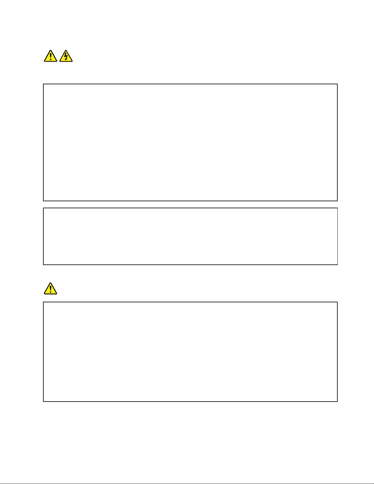
Statement1
DANGER
Electricalcurrentfrompower,telephone,andcommunicationcablesishazardous.
Toavoidashockhazard:
•Donotconnectordisconnectanycablesorperforminstallation,maintenance,orreconfigurationofthis
productduringanelectricalstorm.
•Connectallpowercordstoaproperlywiredandgroundedelectricaloutlet.
•Ensurethatallpowercordconnectorsaresecurelyandcompletelypluggedintoreceptacles.
•Connecttoproperlywiredoutletsanyequipmentthatwillbeattachedtothisproduct.
•Whenpossible,useonehandonlytoconnectordisconnectsignalcables.
•Neverturnonanyequipmentwhenthereisevidenceoffire,water,orstructuraldamage.
•Disconnecttheattachedpowercords,telecommunicationssystems,networks,andmodemsbeforeyou
openthedevicecovers,unlessinstructedotherwiseintheinstallationandconfigurationprocedures.
•Connectanddisconnectcablesasdescribedinthefollowingtablewheninstalling,moving,oropening
coversonthisproductorattacheddevices.
Toconnect:Todisconnect:
1.TurneverythingOFF.
2.First,attachallcablestodevices.
3.Attachsignalcablestoconnectors.
4.Attachpowercordstooutlet.
5.TurndevicesON.
1.TurneverythingOFF.
2.First,removepowercordsfromoutlet.
3.Removesignalcablesfromconnectors.
4.Removeallcablesfromdevices.
Statement2
DANGER
Dangerofexplosionifbatteryisincorrectlyreplaced.
Whenreplacingthelithiumcoincellbattery,useonlythesameoranequivalenttypethatis
recommendedbythemanufacturer .Thebatterycontainslithiumandcanexplodeifnotproperly
used,handled,ordisposedof.
Donot:
•Throworimmerseintowater
•Heattomorethan100°C(212°F)
•Repairordisassemble
Disposeofthebatteryasrequiredbylocalordinancesorregulations.
©CopyrightLenovo2013,2014
v
Page 8
Statement3
CAUTION:
Whenlaserproducts(suchasCD-ROMs,DVDdrives,fiberopticdevices,ortransmitters)are
installed,notethefollowing:
•Donotremovethecovers.Removingthecoversofthelaserproductcouldresultinexposureto
hazardouslaserradiation.Therearenoserviceablepartsinsidethedevice.
•Useofcontrolsoradjustmentsorperformanceofproceduresotherthanthosespecifiedherein
mightresultinhazardousradiationexposure.
DANGER
SomelaserproductscontainanembeddedClass3AorClass3Blaserdiode.Notethefollowing:
Laserradiationwhenopen.Donotstareintothebeam,donotviewdirectlywithoptical
instruments,andavoiddirectexposuretothebeam.
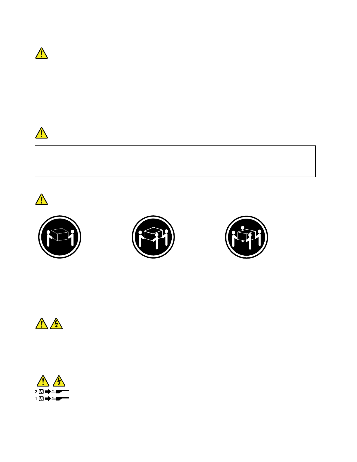
Statement4
≥18kg(39.7lb)≥32kg(70.5lb)≥55kg(121.2lb)
<32kg(70.5lb)<55kg(121.2lb)<100kg(220.5lb)
CAUTION:
Usesafepracticeswhenlifting.
Statement5
CAUTION:
Thepowercontrolbuttononthedeviceandthepowerswitchonthepowersupplydonotturnoff
theelectricalcurrentsuppliedtothedevice.Thedevicealsomighthavemorethanonepower
cord.Toremoveallelectricalcurrentfromthedevice,ensurethatallpowercordsaredisconnected
fromthepowersource.
viThinkServerRD440UserGuideandHardwareMaintenanceManual
Page 9
Statement6
CAUTION:
Ifyouinstallastrain-reliefbracketoptionovertheendofthepowercordthatisconnectedtothe
device,youmustconnecttheotherendofthepowercordtoapowersourcethatiseasilyaccessible
incaseitneedstobedisconnected.
Statement7
CAUTION:
Ifthedevicehasdoors,ensurethatyouremoveorsecurethedoorsbeforemovingorliftingthe
devicetoprotectagainstpersonalinjury.Thedoorswillnotsupporttheweightofthedevice.
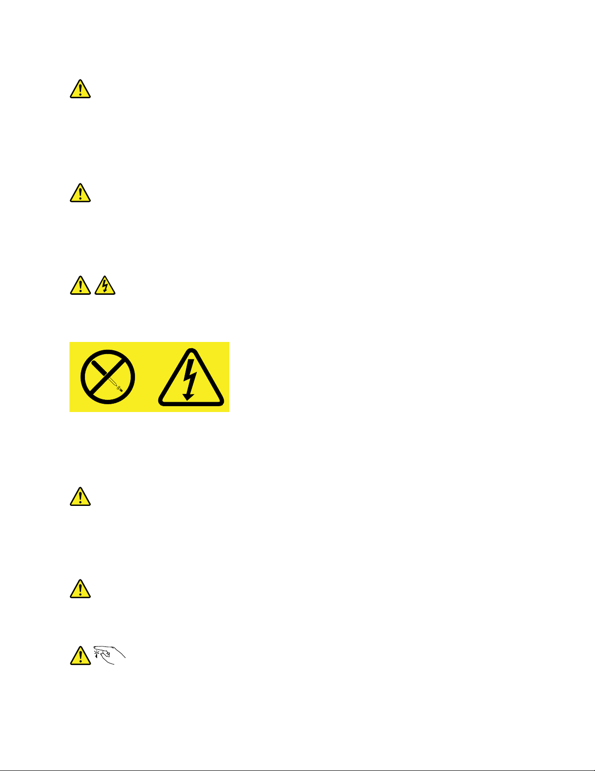
Statement8
CAUTION:
Neverremovethecoveronapowersupplyoranypartthathasthefollowinglabelattached.
Hazardousvoltage,current,andenergylevelsarepresentinsideanycomponentthathasthislabel
attached.Therearenoserviceablepartsinsidethesecomponents.Ifyoususpectaproblemwith
oneoftheseparts,contactaservicetechnician.
Statement9
CAUTION:
Disconnectthehot-swapfancablesbeforeremovingthefanfromthedevicetoprotectagainst
personalinjury.
Statement10
CAUTION:
Thefollowinglabelindicatesasharp-edgehazard.
©CopyrightLenovo2013,2014
vii
Page 10
Statement11
CAUTION:
Thefollowinglabelindicatesapotentialheathazard.
Statement12
DANGER
Overloadingabranchcircuitisapotentialfirehazardandashockhazardundercertainconditions.To
avoidthesehazards,ensurethatyoursystemelectricalrequirementsdonotexceedbranchcurrentratings
attheinstallationsite.
Statement13
CAUTION:
Ensurethattherackissecuredproperlytoavoidtippingwhentheserverunitisextendedontherails.
Statement14
CAUTION:
SomeaccessoryoroptionboardoutputsexceedClass2orlimitedpowersourcelimits.Y ou
mustinstalltheappropriateinterconnectingcablinginaccordancewithyourlocalelectricalcode
requirements.
Statement15
CAUTION:
Thepower-controlbuttononthedevicemayputthedeviceinstandbymodeinsteadofturningoff
thedevice.Inaddition,thedevicemighthavemultipleconnectionstodcpower.T oremoveall
electricalcurrentfromthedevice,ensurethatallconnectionstodcpoweraredisconnectedat
thedcpowerinputterminals.
viiiThinkServerRD440UserGuideandHardwareMaintenanceManual
Page 11
Statement16
CAUTION:
Toreducetheriskofelectricshockorenergyhazards:
•Thisequipmentmustbeinstalledbytrainedservicepersonnelinarestricted-accesslocation,as
definedbyyourlocalelectricalcodeandthelatesteditionofIEC60950.
•Connecttheequipmenttoareliablyearthedsafetyextralowvoltage(SELV)source.AnSELV
sourceisasecondarycircuitthatisdesignedsothatnormalandsinglefaultconditionsdonot
causethevoltagestoexceedasafelevel(60Vdirectcurrent).
•Thebranchcircuitovercurrentprotectionmustberatedinaccordancewithlocalelectricalcode
requirements.
•Use1.3mm
2
or16AmericanWireGauge(AWG)copperconductoronly,notexceeding3meters
inlength.
•Torquethewiring-terminalscrewsto1.4newton-metersor12inch-pounds.
•Provideareadilyavailable,approvedandrateddisconnectdeviceinthefieldwiring.
Statement17
CAUTION:
ThisproductcontainsaClass1Mlaser.Donotviewdirectlywithopticalinstruments.
Statement18
CAUTION:
Donotplaceanyobjectontopofrack-mountedproducts.
Statement19
CAUTION:
Hazardousmovingparts.Keepfingersandotherbodypartsaway.
©CopyrightLenovo2013,2014
ix
Page 12

Statement20
CAUTION:
Alithiumionbatteryisprovided.Toavoidpossibleexplosion,donotburnthebattery.Replacethe
batteryonlywiththeLenovo-approvedpart.Recycleordiscardthebatteryasinstructedbylocal
regulations.
Productsthatarenotassessed
Typicalproductsthatarenotassessedincludebutnotlimitedtothefollowing:
•ServerandIT-rackcomponents(forexample,uninterruptiblepowersuppliesandcurrentdistribution
systems)
•DevicesinITrooms(forexample,bulkstorageunitsandnetworkproducts)
•Industriallow-voltageswitchgear
xThinkServerRD440UserGuideandHardwareMaintenanceManual
Page 13

Chapter1.Generalinformation
Thischapterprovidessomegeneralinformationaboutyourproduct.
Thischaptercontainsthefollowingitems:
•“Introduction”onpage1
•“Serverdocumentation”onpage2
Introduction
ThisdocumentationforyourLenovo
specifications,componentlocations,configurationinstructions,hardwarereplacementprocedures,and
basictroubleshootinganddiagnostics.
YourservercomeswithadocumentationDVDthatcontainsvariousserverdocumentstohelpyouuseand
maintaintheserver.Meanwhile,yourservercomeswithaThinkServerEasyStartupDVDthatprovidesa
convenientsolutionforconfiguringtheserverandinstallinganoperatingsystem.
TheLenovoLimitedWarranty(LLW)containsthewarrantytermsthatapplytotheproductyoupurchasedfrom
Lenovo.ReadtheLLWonthedocumentationDVDthatcomeswithyourserver.Aprintablegenericversion
ofthelatestLLWalsoisavailableinmorethan30languagesathttp://www.lenovo.com/warranty/llw_02.If
youcannotobtaintheLLWthroughthedocumentationDVDorLenovoWebsite,contactyourlocalLenovo
officeorresellertoobtainaprintedversionoftheLLW,freeofcharge.
®
ThinkServer
®
productcontainsinformationabouttheserverfeatures,
Forwarrantyservice,consulttheworldwideLenovoSupporttelephonelist.Telephonenumbersaresubject
tochangewithoutnotice.Themostup-to-datetelephonelistforLenovoSupportisalwaysavailableonthe
Websiteathttp://www.lenovo.com/support/phone.Ifthetelephonenumberforyourcountryorregionisnot
listed,contactyourLenovoresellerorLenovomarketingrepresentative.
Toobtainthemostup-to-dateinformationabouttheserver,goto:
http://www.lenovo.com/thinkserver
LenovomaintainspagesontheWorldWideWeb,whereyoucangetthelatesttechnicalinformationand
downloaddocumentationordevicedriversandupdates.T oaccesstheLenovoSupportWebsite,goto:
http://www.lenovo.com/support
©CopyrightLenovo2013,2014
1
Page 14

Recordinformationaboutyourserverinthefollowingtable.Youwillneedtheinformationifyoueverneed
tohaveyourserverserviced.
Forwheretofindtheproductinformationlabelonthechassis,see“Machinetype,model,andserialnumber
label”onpage14
.
Productname
Machinetypeandmodel(MT-M)
Serialnumber(S/N)
Dateofpurchase
______________________________________________
______________________________________________
______________________________________________
______________________________________________
YoucanregisteryourserverwithLenovobyfollowingtheinstructionsat:
http://www.lenovo.com/register
Whenyouregisteryourserver,informationisenteredintoadatabase,whichenablesLenovotocontact
youincaseofarecallorothersevereproblem.AfteryouregisteryourserverwithLenovo,youwillreceive
quickerservicewhenyoucallLenovoforhelp.Inaddition,somelocationsofferextendedprivilegesand
servicestoregisteredusers.
Serverdocumentation
Thistopicprovidesgeneraldescriptionsofthevariousdocumentationforyourserverandinstructionson
howtoobtainallthedocumentation.
Printeddocuments
Thefollowingdocumentsareprintedoutandcontainedinyourserverpackage.
•ReadMeFirst
Thisisamultilingualdocumentyoushouldreadfirst.Thisdocumentguidesyoutoreadthecomplete
warranty,support,andsafetyinformationonthedocumentationDVDthatcomeswithyourserverbefore
usingtheproduct.Thisdocumentalsoprovidesinformationabouthowtofindthemostup-to-date
informationontheLenovoSupportWebsite.
•RackInstallationInstructions
Thisdocumentprovidesinstructionsonhowtoinstallyourserverintoastandardrackcabinetbyusing
therailkitshippedwiththeserver.
Note:AprintedEnglishversionofthisdocumentisincludedinyourserverpackage.PDFversionsof
otherlanguagesareprovidedonthedocumentationDVDthatcomeswiththeserver.
2ThinkServerRD440UserGuideandHardwareMaintenanceManual
Page 15

DocumentationDVD
ThedocumentationDVD,whichcomeswithyourserver,containsvariousdocumentsforyourserverin
PortableDocumentFormat(PDF)andHyperTextMarkupLanguage(HTML).ThedocumentationDVDisnot
bootable.ToviewthedocumentsontheDVD,youwillneedacomputerwithaWebbrowserandtheAdobe
Readerprogram,whichisavailablefordownloadat:
http://www.adobe.com
TostartthedocumentationDVD,inserttheDVDintotheopticaldrive.TheDVDisAutoPlayenabledand
startsautomaticallyinmostMicrosoft
®
Linux
operatingsystem,openthelaunch.htmfilelocatedintherootdirectoryoftheDVD.
®
Windows
®
environments.IftheDVDfailstostartorifyouareusinga
Note:LenovomaintainspagesontheWorldWideWeb,whereyoucangetthelatesttechnicalinformation
anddownloaddocumentationordevicedriversandupdates.Someinformationinthedocumentsonthe
documentationDVDmightchangewithoutnoticeafterthefirstreleaseoftheDVD.Y oucanalwaysobtainall
themostup-to-datedocumentationforyourserverfromtheLenovoWebsiteat:
http://www.lenovo.com/UserManuals
ThefollowingdocumentsareonthedocumentationDVDthatcomeswithyourserver:
•Safety,Warranty,andSupportInformation
Thisisamultilingualdocumentthatincludesallthesafetystatementsforyourproductinmorethan30
languages.Besuretoreadandunderstandallthesafetystatementsbeforeusingtheproduct.This
documentalsoincludestheLenovowarrantystatement,CustomerReplaceableUnits(CRUs)information,
andinformationabouthowtocontacttheLenovoCustomerSupportCenter.
•LenovoLicenseAgreement
ThisdocumentincludesthetermsandconditionsoftheLenovoLicenseAgreement.
•UserGuideandHardwareMaintenanceManual
Thisdocumentprovidesdetailedinformationtohelpyougetfamiliarwithyourserverandhelpyou
use,configure,andmaintainyourserver.Someinformationinthisdocument,ifspecified,isintended
forservicetechniciansonly.
•RackInstallationInstructions
Thisdocumentprovidesinstructionsonhowtoinstallyourserverintoastandardrackcabinetbyusing
therailkitshippedwiththeserver.
•ThinkServerManagementModuleUserGuide
Thisdocumentprovidesinformationaboutserverremotemanagement.ThisdocumentisinEnglishonly.
YoumightfindthisdocumentonthedocumentationDVDthatcomeswithyourserver.Ifnot,downloadit
fromtheLenovoWebsiteat:
http://www.lenovo.com/UserManuals
Note:T oobtainadvancedremotemanagementfunctions,installaThinkServerManagementModule
Premium(TMMPremium)ontheTMMPremiumconnectoronthesystemboard.See“Installingor
removingtheThinkServerManagementModulePremium”onpage127
.
•MegaRAIDSASSoftwareUserGuide
ThisdocumentprovidesinformationaboutRedundantArrayofIndependentDisks(RAID)andhowto
usetheutilityprogramstoconfigure,monitor,andmaintainyourserverRAIDandrelateddevices.This
documentisinEnglishonly.
Note:RefertothisdocumentforhardwareRAIDinformationifyouhavearequiredRAIDcardinstalled
intheserver.See“InstallingorremovingtheRAIDcard”onpage105
.Forinformationaboutthe
ThinkServerRAID300(alsoknownastheonboardSASsoftwareRAID),see“ConfiguringtheThinkServer
RAID300”onpage76.
Chapter1.Generalinformation3
Page 16

Supplementarydocuments
Dependingonyourserver,yourdocumentationDVDmightcontainsupplementarydocumentsprovidedby
Lenovo,includingdocumentsforEthernetcards,hostbusadapters(HBAs),orotheroptionalparts.
4ThinkServerRD440UserGuideandHardwareMaintenanceManual
Page 17

Chapter2.Serversetuproadmap
Thischapterprovidesageneralroadmaptoguideyouthroughsettingupyourserver.
Theserversetupprocedurevariesdependingontheconfigurationoftheserverwhenitwasdelivered.In
somecases,theserverisfullyconfiguredandyouneedtoconnecttheservertothenetworkandanacpower
source,andthenyoucanturnontheserver.Inothercases,theserverneedstohavehardwaredevices
installed,requireshardwareandfirmwareconfiguration,andrequiresanoperatingsystemtobeinstalled.
Thegeneralprocedureforsettingupyourserveris:
1.Unpacktheserverpackage.See“Serverpackage”onpage7.
2.Installanyrequiredhardwareorserveroptions.SeetherelatedtopicsinChapter6“Installing,removing,
orreplacinghardware”onpage85.
3.Installtheserverintoastandardrackcabinetbyusingtherailkitshippedwiththeserver.SeetheRack
InstallationInstructionsthatcomeswiththeserver.
4.ConnecttheEthernetcablesandpowercordstotheserver.See“Rearviewoftheserver”onpage
29tolocatetheconnectors.
5.Turnontheservertoverifyoperation.See“Turningontheserver”onpage61.
6.ReviewtheUnifiedExtensibleFirmwareInterface(UEFI)BasicInputOutputSystem(BIOS)settingsand
customizeasneeded.See“UsingtheSetupUtilityprogram”onpage63.
7.ConfigureRAIDandinstalltheoperatingsystemanddevicedrivers.See“UsingtheThinkServer
EasyStartupprogram”onpage71and“ConfiguringRAID”onpage74.
8.Installanyadditionaldriversrequiredforaddedfeatures.Refertotheinstructionsthatcomewith
thehardwareoption.
9.ConfigureEthernetsettingsintheoperatingsystembyreferringtotheoperatingsystemhelp.Thisstep
isnotrequirediftheoperatingsystemwasinstalledusingtheThinkServerEasyStartupprogram.
10.Checkforfirmwareupdates.See“Updatingthefirmware”onpage83.
11.Installmanagementapplicationsandanyotherapplications.Refertothedocumentationthatcomes
withtheapplicationsthatyouwanttoinstall.
©CopyrightLenovo2013,2014
5
Page 18

6ThinkServerRD440UserGuideandHardwareMaintenanceManual
Page 19
Chapter3.Productoverview
Thischapterprovidesinformationabouttheserverpackage,features,specifications,softwareprograms,
andcomponentlocations.
Thischaptercontainsthefollowingitems:
•“Serverpackage”onpage7
•“Features”onpage8
•“Specifications”onpage12
•“Software”onpage12
•“Locations”onpage14
Serverpackage
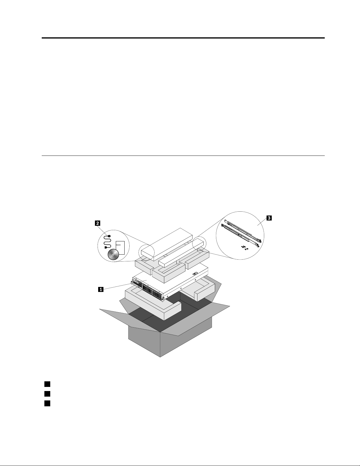
Theserverpackageincludestheserver,powercords,arailkit,printeddocumentation,adocumentation
DVD,andsoftwaremedia.
Note:Dependingonthemodel,yourservermightlookslightlydifferentfromthefollowingillustration.
Figure1.Serverpackage
1Server
2Materialbox(includingpowercords,printeddocumentation,adocumentationDVD,andsoftwaremedia)
3Railkit
©CopyrightLenovo2013,2014
7
Page 20

Features
Thistopicprovidesgeneralinformationabouttheserverfeaturesforvariousmodels.Dependingonyour
specificmodel,somefeaturesmightvaryorunavailable.Forinformationaboutyourspecificmodel,usethe
SetupUtilityprogram.See“ViewinginformationintheSetupUtilityprogram”onpage63.Youalsocanrefer
tothePersonalSystemsReferencedocumentforThinkServerproductsat:
http://www.lenovo.com/psref/
Microprocessor
OneortwoIntel
®
®
Xeon
microprocessors(internalcachesizevariesbymodel)
ForalistofThinkServermicroprocessoroptions,goto:
http://www.lenovo.com/thinkserver
Memory
Yourserverhas12memoryslots.Formoreinformation,see“Memorymoduleinstallationrules”onpage99
Powersupply
Oneortwo800-watthot-swapredundantpowersupplies(Universalinputandcompliantwith80PLUSGold)
Systemfan
Asystemfancagewithfivehot-swapsystemfansandonedummysystemfan
Internaldrive
Internaldrivesaredevicesthatyourserverusestoreadandstoredata.Theinternaldrivessupported
byyourservervarybymodel.
•Harddiskdrive
–Uptoeight3.5-inchhot-swapSerialAdvancedTechnologyAttachment(SATA)orSerialAttached
SCSI(SAS)harddiskdrives(SCSIistheacronymforSmallComputerSystemInterface)orSATA
solid-statedrives
–Uptotwelve3.5-inchhot-swapSATAorSASharddiskdrivesorSATAsolid-statedrives(uptotwo
solid-statedrivesaresupportedifyouwanttoinstallbothharddiskdrivesandsolid-statedrives
intotheserver)
–Uptoeight2.5-inchhot-swapSATAorSASharddiskdrivesorSATAsolid-statedrives
–Uptosixteen2.5-inchhot-swapSATAorSASharddiskdrivesorSATAsolid-statedrives(uptotwo
solid-statedrivesaresupportedifyouwanttoinstallbothharddiskdrivesandsolid-statedrives
intotheserver)
–SupportPCIExpresssolid-statedrives
Thefollowingservermodelsalsoareavailable:
.
–Servermodelswithoutharddiskdrivesorsolid-statedrives
–Servermodelswithoutharddiskdrives,solid-statedrives,backplanes,RAIDcards,andrelatedcables
Note:Theterm“2.5-inchhot-swapharddiskdrives”or“2.5-inchharddiskdrives”hereinafterreferstoall
thesupportedtypesof2.5-inchharddiskdrives,includingsolid-statedrives.
•Opticaldrive
8ThinkServerRD440UserGuideandHardwareMaintenanceManual
Page 21

–OneslimSATAopticaldriveinsomemodels
Externaldrives
Yourserversupportsexternaltapedrivesthatenableyoutostoredataintapes.Toinstallanexternaltape
drive,see“Installinganexternaltapedrive”onpage159.
Expansionslot
•Tworisercardassemblyslotsonthesystemboard
•TwoPeripheralComponentInterconnect(PCI)Expresscardslotsontherisercardassembly1
•ThreePCIExpresscardslotsontherisercardassembly2
Fordetailedinformation,see“Rearviewoftheserver”onpage29
.
Input/Output(I/O)features
•Oneserialconnectorontherearpanel
•OneVideoGraphicsArray(VGA)connectoronthefrontpanelinsomemodelsandoneVGAconnector
ontherearpanel
•SixUSB2.0connectors(twoonthefrontpanelandfourontherearpanel)
•ThreeRJ-45Ethernetconnectorsontherearpanel(Ethernetconnector0isforsystemmanagement)
Forthelocationinformationabouttheconnectors,refertotherelatedtopicsin“Locations”onpage14.
Videosubsystem
AnintegratedgraphicscontrollerintheThinkServerManagementModule(TMM),whichalsoisknown
astheBaseboardManagementController(BMC)chip,onthesystemboardtosupportVGAconnectors
forconnectingvideodevices
Ethernetconnectivity
TherearethreeRJ-45Ethernetconnectorsontherearpanelwith10megabitspersecond(Mbps),100
Mbps,or1000Mbpsnetworkconnectivity.TheEthernetconnector0isforsystemmanagementbydefault.
However,youalsocansettheEthernetconnector1or2forsystemmanagementuseintheSetupUtility
program.See“SettingthemodeoftheEthernetconnectors”onpage69
.
Formoreinformation,see“Rearviewoftheserver”onpage29
.
Reliability,availability,andserviceability
Reliability,availability,andserviceability(hereinafterreferredtoasRAS)arethreeimportantserverdesign
features.TheRASfeatureshelpyoutoensuretheintegrityofthedatastoredontheserver,theavailabilityof
theserverwhenyouneedit,andtheeasewithwhichyoucandiagnoseandcorrectproblems.
YourserverhasthefollowingRASfeatures:
Chapter3.Productoverview9
Page 22

•Securityfeatures
–Administratorpasswordanduserpasswordtohelpyouprotectunauthorizedaccesstotheserver
(see“Usingpasswords”onpage67
)
–Hot-swapredundantpowersuppliestoprotectagainstsignificantinterruptiontotheoperationofthe
systemwhenapowersupplyfails(forservermodelsthatcomewithonepowersupply,youcan
purchaseahot-swapredundantpowersupplyoptionfromLenovoandinstallitintoyourserverasthe
secondpowersupplyforredundancy)
–RedundantArrayofIndependentDisks(RAID)configurationforimprovingdatastoragereliabilityand
faulttolerance(see“ConfiguringRAID”onpage74
)
–Remotemonitoringorcontrolbyanadministratortoprovideprotectionorhelp
–ThinkServerT rustedPlatformModule(TPM),whichisasecuritychip,tohelpenhanceserversecurity
Note:TheTPMisonlyavailableinsomemodels.
•Basicsystemmanagementfeatures
–Abilitytostorethepower-onself-test(POST)hardwaretestresults
–BIOSSetupUtilityprogram
TheBIOSSetupUtilityprogramhelpsyouviewtheserverinformationandconfiguretheserverinthe
pre-operatingsystemenvironment.See“UsingtheSetupUtilityprogram”onpage63.
–TMM(alsoknownasBMC)andIntelligentPlatformManagementInterface(IPMI)2.0
ThesystemboardplatformmanagementsubsystemisbasedontheintegratedTMMfeatures.The
TMMisamanagementchipthatisintegratedonthesystemboardofyourserver.WiththeTMM,no
matterwhatconditiontheserveroperatingsystemisinandnomatteriftheserverisonoroff,aslong
astheserverisconnectedtonetworkandanacpowersource,theinteractionwiththeTMM-controlled
serverscanbeachievedthroughsystemnetwork.Theusercanobtaintheserverhardwarehealth
informationandsystemeventlog(SEL),andisabletoconducttheoperationsincludingturningonor
offtheserver,restartingtheserver,andsoon.Thispartofservermanagementisindependentofthe
operatingsystemandiscalledout-of-bandmanagement.
ThesystemboardplatformmanagementsubsystemconsistsoftheintegratedTMM,communication
buses,sensors,theBIOS,andservermanagementfirmware.Itisresponsibleforerrorreporting,
systempowercontrol,thermalmonitoring,systemfancontrol,andothermanagementfeatures.The
TMMprovidessystemmanagementandmonitoringfeaturesbasedontheIPMI2.0specification.IPMI
helpslowertheoverallcostsofservermanagement.Y oucanfindmoreinformationaboutIPMI2.0
fromtheWebsiteofIntel.TheTMMalsosupportssomenon-IPMIfeatures,suchastheDynamicHost
ConfigurationProtocol(DHCP)andthePlatformEnvironmentControlInterface(PECI),toprovide
moresystemmanagementfunctions.
Youcanfindthedefaultusername,password,andotherinformationfortheTMMintheThinkServer
ManagementModuleUserGuide,whichisavailablefordownloadat:
http://www.lenovo.com/UserManuals
–Hot-swapfeature
Yourserversupportshot-swapharddiskdrives,hot-swapsystemfans,andhot-swapredundant
powersupplies.Withthehot-swapfeature,youcaninstall,remove,orreplaceahot-swapdevice
withoutturningofftheserver.
–PrebootExecutionEnvironment(PXE)
TheIntelPXEtechnologyenablesyoutostartyourcomputers,loadanoperatingsystem,ordeploy
executableimagesfromaremoteserverbyusinganetworkinterface.Theoperationcanbedone
independentlyoflocaldatastoragedevices(suchasharddiskdrives)oroperatingsystems.
–RAID
10ThinkServerRD440UserGuideandHardwareMaintenanceManual
Page 23

YourserversupportsonboardSATAsoftwareRAID.IfarequiredRAIDcardisinstalled,yourserver
alsosupportsadvancedSATA/SAShardwareRAIDconfigurations.Fordetailedinformation,see
“ConfiguringRAID”onpage74
.
–Statuslight-emittingdiodes(LEDs)anddiagnosticLEDs
FormoreinformationabouttheLEDsforyourserver,refertotherelatedtopicsin“Locations”on
page14.
–Softwareprograms
Formoreinformationaboutthesoftwareprograms,see“Software”onpage12.
–WakeonLAN
WhentheWakeonLANfeatureisenabledonacomputerthatisconnectedtoaLAN,anetwork
administratorcanremotelyturnonorwakeupthecomputerfromamanagementconsoleusingremote
networkmanagementsoftware.Besides,manyotherfunctions,suchasdatatransferandsoftware
updates,canbeperformedremotelywithoutremoteattendanceandcanbedoneafternormalworking
hoursandonweekendstosavetimeandincreaseproductivity.
•Advancedsystemmanagementfeatures
TheadvancedsystemmanagementfeaturesareonlyavailablewhentheTMMdetectsthepresenceofa
ThinkServerManagementModulePremium(TMMPremium),whichalsoisknownasintegratedkeyboard,
video,andmouse(iKVM)key.TheTMMPremiumisaremotemanagementmodule.Y oucanpurchase
aTMMPremiumfromLenovoandinstallitontheTMMPremiumconnector(alsoknownasiKVM
connector)onthesystemboardofyourservertoenabletheiKVMfunctionandactivatetheadvanced
systemmanagementfeatures.
Formoreinformationaboutadvancedsystemmanagement,refertotheThinkServerManagementModule
UserGuide,whichisavailablefordownloadat:
http://www.lenovo.com/UserManuals
Chapter3.Productoverview11
Page 24

Specifications
Thistopicliststhephysicalspecificationsforyourserver.
Dimensions
Widthwithoutrackhandles:442mm(17.4inches)
Widthwithrackhandles:482.4mm(19inches)
Depthwithoutrackhandles:720.6mm(28.37inches)
Depthwithrackhandles:734mm(28.9inches)
Height:87.6mm(3.45inches)
Weight
Theproductweightvariesdependingondifferentsystemconfigurations.
Rangeofproductweightwithoutpackage:16kg(35.27lb)to28kg(61.73lb)
Rangeofproductweightwithpackage:19kg(41.89lb)to35kg(77.16lb)
Environment
•Airtemperature:
Operating:10°Cto35°C(50°Fto95°F)
Storage:-40°Cto70°C(-40°Fto158°F)inoriginalshippingpackage
•Altitude:0to3048m(0to10000ft)inanunpressurizedenvironment
•Humidity:
Operating:8%to80%(non-condensing)
Storagewithoutpackage:8%to80%(non-condensing)
Storagewithpackage:8%to90%(non-condensing)
Electricalinput
•Universalinput:
–Lowrange:
Minimum:100Vac
Maximum:127Vac
Inputfrequencyrange:50to60Hz
–Highrange:
Minimum:200Vac
Maximum:240Vac
Inputfrequencyrange:50to60Hz
Software
Thistopicprovidesinformationaboutthesoftwareprogramsthatyoucanusetohelpyousetup,use,
andmaintaintheserver.
ThinkServerEasyStartup
TheThinkServerEasyStartupprogramsimplifiestheprocessofconfiguringRAIDandinstallingsupported
MicrosoftWindowsandLinuxoperatingsystemsanddevicedriversonyourserver.Thisprogramisprovided
withyourserveronaself-starting(bootable)ThinkServerEasyStartupDVD.Theuserguidefortheprogram
12ThinkServerRD440UserGuideandHardwareMaintenanceManual
Page 25

alsoisontheDVDandcanbeaccesseddirectlyfromtheprograminterface.Fordetailedinformation,see
“UsingtheThinkServerEasyStartupprogram”onpage71
.
ThinkServerEasyUpdateFirmwareUpdater
TheThinkServerEasyUpdateFirmwareUpdaterprogram(hereinafterreferredtoastheFirmwareUpdater
program)enablesyoutomaintainyourserverfirmwareup-to-dateandhelpsyouavoidunnecessaryserver
outages.TheFirmwareUpdaterprogramisprovidedontheLenovoSupportWebsite.Formoreinformation
aboutdownloadingandusingtheFirmwareUpdaterprogram,see“Updatingthefirmware”onpage83
LenovoThinkServerEasyManage
TheLenovoThinkServerEasyManageprogramenablesenterpriseuserstocontrolandmonitormultiple
LenovoserverswithinaLANremotely.
Fordetailedinformation,see“UsingtheLenovoThinkServerEasyManageprogram”onpage83.
BIOSandTMMupdateutilities
TheBIOSandTMM(alsoknownasBMC)firmwarekeepsupdatingaftertheshipmentoftheserver.
LenovomaintainspagesontheSupportWebsiteandprovidestheBIOSandTMMupdateutilitieswith
instructionsfordownloadtohelpyouupdatetheBIOSandTMMfirmwareifneeded.Formoreinformation,
see“UpdatingorrecoveringtheBIOS”onpage70
and“Updatingthefirmware”onpage83.
RAIDconfigurationutilities
.
YourserversupportsonboardSATAsoftwareRAID.IfarequiredRAIDcardisinstalled,yourserveralso
supportsadvancedSATA/SAShardwareRAIDconfigurations.Fordetailedinformation,see“Configuring
RAID”onpage74.
Remotemanagementsoftware
TheintegratedTMMprovidesbasicremotemanagementfeaturesfortheserver.Theadd-onTMMPremium
optionprovidesadvancedremotemanagementfeaturesfortheserver.
Fordetailedinformationabouttheremotemanagementsoftwareandserverremotemanagement,referto
theThinkServerManagementModuleUserGuide,whichisavailablefordownloadat:
http://www.lenovo.com/UserManuals
ThinkServerSmartGridTechnology
TheThinkServerSmartGridTechnologyprogramhelpsadministratorstomonitorandmanageserver
performance,especiallythepowerconsumptionforgroupsofserversequippedwiththeIntelIntelligent
PowerNodeManagertechnology.
LenovoprovidesatrialversionoftheThinkServerSmartGridTechnologyprogramwithafree90-day
subscription.After90days,youmustrenewthelicensetocontinueusingtheprogram.Youcanpurchase
thelicensefromLenovotoactivatetheThinkServerSmartGridTechnologyprogramandexpandthe
managementcapabilityoftheprogramwhenthefreetrialends.
TodownloadtheThinkServerSmartGridTechnologyprogram,gotohttp://www.lenovo.com/driversand
followtheinstructionsontheWebpage.
FordetailedinformationaboutusingtheThinkServerSmartGridTechnologyprogram,refertothehelp
systemfortheprogram.
Chapter3.Productoverview13
Page 26

Diagnosticprograms
Thefollowingdiagnosticprogramsareavailableforyoutodiagnoseserverproblems:
•ThinkServerDiagnosticTool
•ThinkServerSystemProfileCollectionT ool
Formoreinformation,see“Usingadiagnosticprogram”onpage204.
Locations
Thistopicprovidesinformationtohelpyoulocateyourservercomponents.
Machinetype,model,andserialnumberlabel
Thistopichelpsyoutolocatethelabelthatcontainsthemachinetype,model,andserialnumberinformation
foryourserver.
WhenyoucontactLenovoforhelp,themachinetype,model,andserialnumberinformationhelpssupport
technicianstoidentifyyourserverandprovidefasterservice.
Theillustrationsinthistopicshowthemachinetype,model,andserialnumberlabelsonservermodelswith
differenthard-disk-driveconfigurations.Dependingonthemodel,yourservermightlookslightlydifferent
fromtheillustrationsinthistopic.
14ThinkServerRD440UserGuideandHardwareMaintenanceManual
Page 27
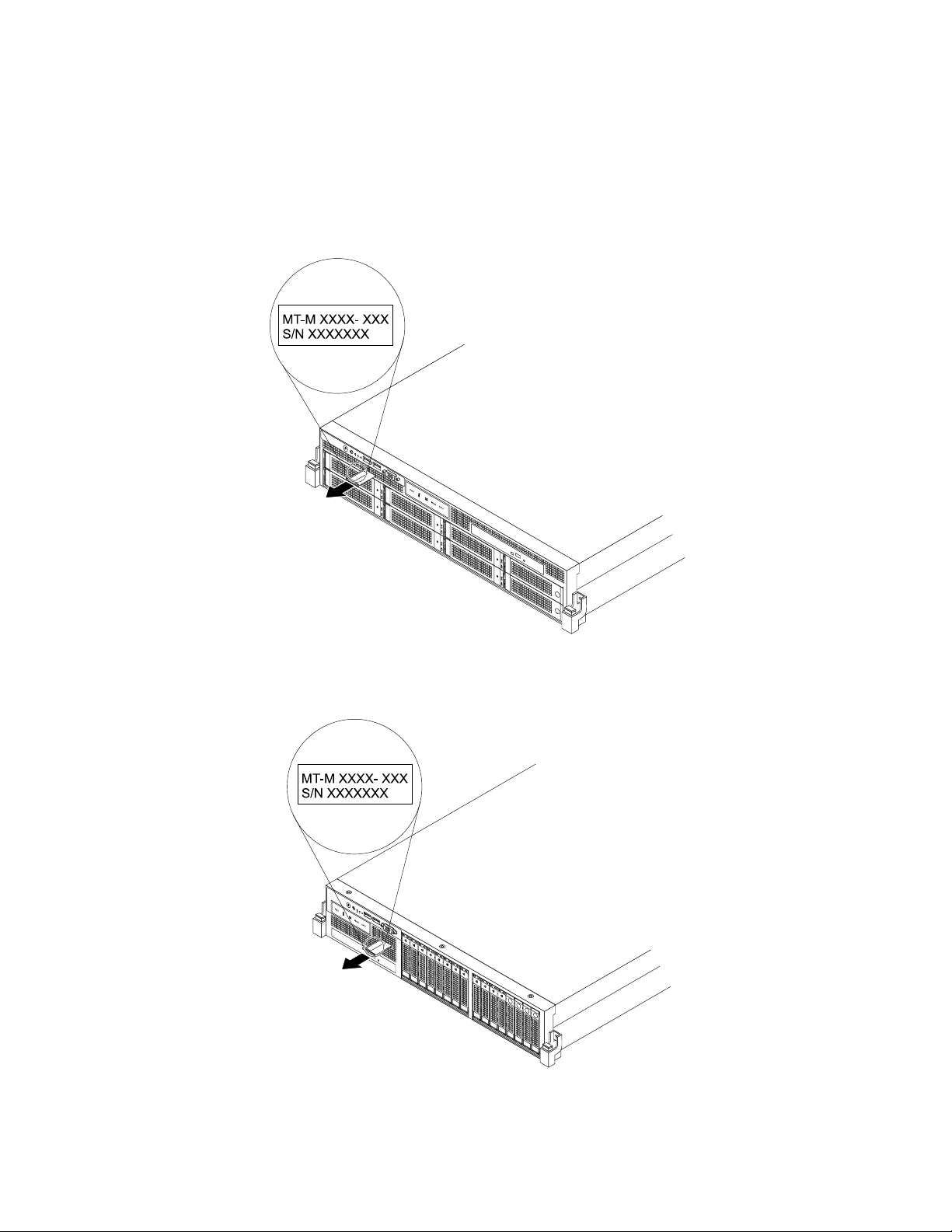
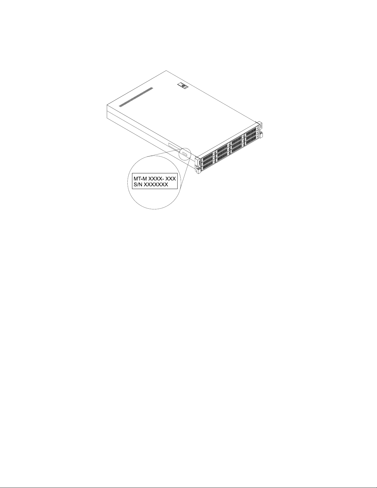
Themachinetype,model,andserialnumberlabelisattachedonthepull-outinformationcardinthe
followingservermodels:
•Servermodelswitheight3.5-inchhard-disk-drivebays
•Servermodelswith2.5-inchhard-disk-drivebays
Thepull-outinformationcardisasmallplastictabandcanbeslidoutofthefrontofthechassis.
Figure2.Labelonservermodelswitheight3.5-inchhard-disk-drivebays
Figure3.Labelonservermodelswith2.5-inchhard-disk-drivebays
Chapter3.Productoverview15
Page 28
Forservermodelswithtwelve3.5-inchhard-disk-drivebays,themachinetype,model,andserialnumber
labelisattachedontheleftsideoftheserver.
Figure4.Labelonservermodelswithtwelve3.5-inchhard-disk-drivebays
Frontviewoftheserver
Thistopicprovidesinformationtohelpyoulocatethepartsonthefrontoftheserver.
Thefrontviewoftheservervariesbymodel.Theillustrationsinthistopicshowtheserverfrontviews
basedonthesupportedharddiskdrives:
•“Frontviewofservermodelswitheight3.5-inchhard-disk-drivebays”onpage17
•“Frontviewofservermodelswithtwelve3.5-inchhard-disk-drivebays”onpage18
•“Frontviewofservermodelswith2.5-inchhard-disk-drivebays”onpage21
Note:Dependingonthemodel,yourservermightlookslightlydifferentfromtheillustrationsinthistopic.
16ThinkServerRD440UserGuideandHardwareMaintenanceManual
Page 29
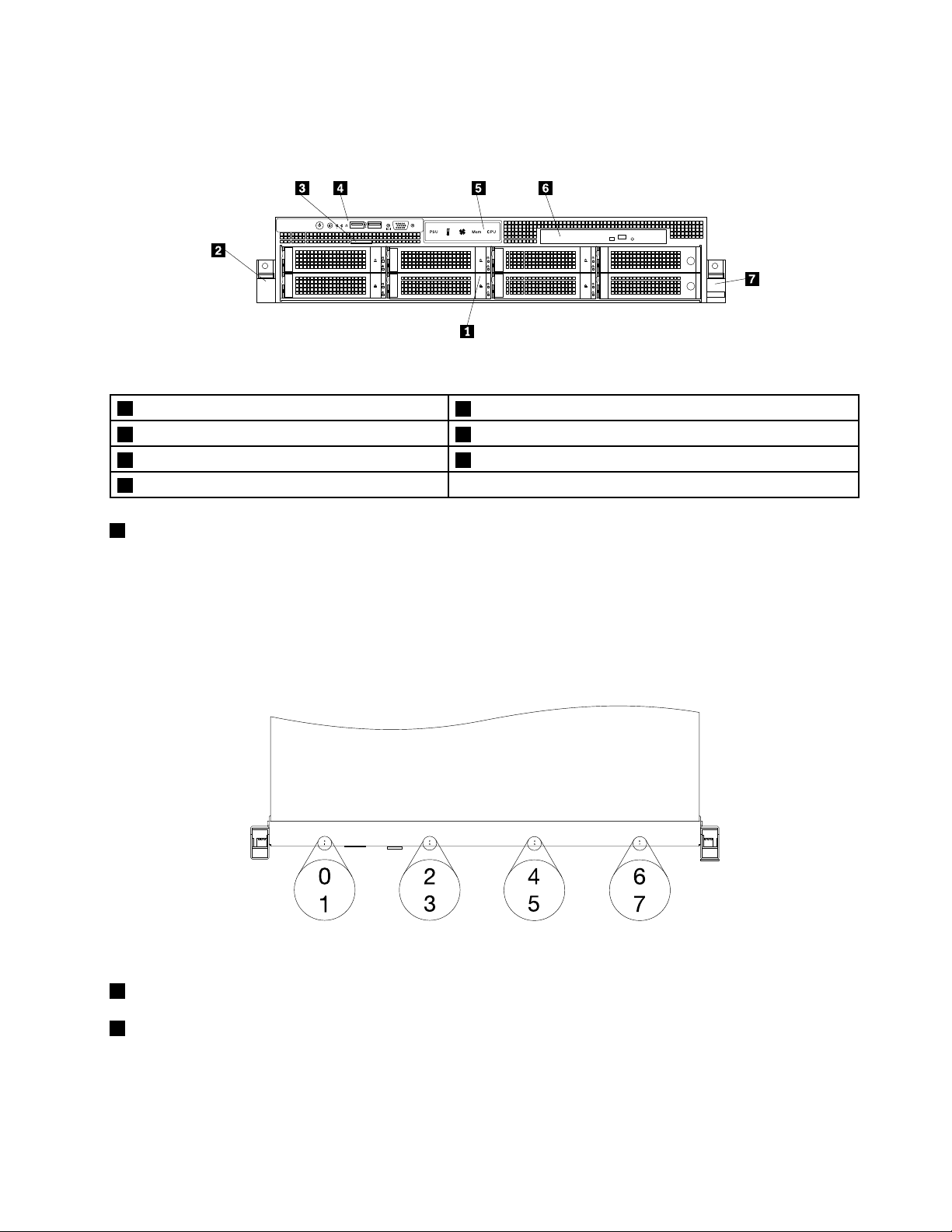
Frontviewofservermodelswitheight3.5-inchhard-disk-drivebays
Thefollowingillustrationshowsthefrontviewofservermodelswitheight3.5-inchhard-disk-drivebays.
Figure5.Frontviewofservermodelswitheight3.5-inchhard-disk-drivebays
13.5-inchhard-disk-drivearea
2Rackhandle(left)6Slimopticaldrive(availableinsomemodels)
3Pull-outinformationcard
4Frontpanel
13.5-inchhard-disk-drivearea
5Diagnosticpanel(variesbymodel)
7Rackhandle(right)
TheElectromagneticInterference(EMI)integrityandcoolingoftheserverareprotectedbyhavingalldrive
bayscoveredoroccupied.Thenumberoftheinstalledharddiskdrivesinyourservervariesbymodel.The
vacanthard-disk-drivebaysareoccupiedbydummyhard-disk-drivetrays.
Forservermodelswitheight3.5-inchhard-disk-drivebays,thehard-disk-drivebaynumbersaremarkedon
thetopedgeofthefrontbezel.
Figure6.3.5-inchhard-disk-drivebaynumbers(topviewoftheserver)
2Rackhandle(left)
7Rackhandle(right)
Ifyourserverisinstalledinarackcabinet,youcanusetherackhandlestohelpyouslidetheserverout
oftherackcabinet;orusetherackhandlesandscrewstosecuretheserverintherackcabinetsothat
theservercannotslideout,especiallyinvibration-proneareas.Formoreinformation,refertotheRack
InstallationInstructionsthatcomeswithyourserver.
Chapter3.Productoverview17
Page 30
3Pull-outinformationcard
Themachinetype,model,andserialnumberlabeloftheserverisattachedonthepull-outinformationcard.
See“Machinetype,model,andserialnumberlabel”onpage14.
4Frontpanel
Fordetailedinformationaboutthecontrols,connectors,andstatusLEDsonthefrontpanel,see“Front
panel”onpage22.
5Diagnosticpanel
Thediagnosticpanelvariesbymodel.Fordetailedinformation,see“Diagnosticmodule”onpage24.
6Slimopticaldrive
SomeservermodelscomewithaslimSATAopticaldrive.
Frontviewofservermodelswithtwelve3.5-inchhard-disk-drivebays
Thefollowingillustrationshowsthefrontviewofservermodelswithtwelve3.5-inchhard-disk-drivebays.
Figure7.Frontviewofservermodelswithtwelve3.5-inchhard-disk-drivebays
13.5-inchhard-disk-drivearea
2Rackhandle(left)7NIC2statusLED
3FrontUSBconnectors(2)8SystemerrorLED
4PowerbuttonwithpowerstatusLED
5Systemidentificationbutton(IDbutton)withIDLED
6NetworkInterfaceController(NIC)1statusLED
9Rackhandle(right)
18ThinkServerRD440UserGuideandHardwareMaintenanceManual
Page 31

13.5-inchhard-disk-drivearea
TheEMIintegrityandcoolingoftheserverareprotectedbyhavingalldrivebayscoveredoroccupied.
Thenumberoftheinstalledharddiskdrivesinyourservervariesbymodel.Thevacanthard-disk-drive
baysareoccupiedbydummyhard-disk-drivetrays.
Forservermodelswithtwelve3.5-inchhard-disk-drivebays,thehard-disk-drivebaynumbersaremarked
onthetopedgeofthefrontbezel.
Figure8.3.5-inchhard-disk-drivebaynumbers(topviewoftheserver)
2Rackhandle(left)
9Rackhandle(right)
Ifyourserverisinstalledinarackcabinet,youcanusetherackhandlestohelpyouslidetheserverout
oftherackcabinet;orusetherackhandlesandscrewstosecuretheserverintherackcabinetsothat
theservercannotslideout,especiallyinvibration-proneareas.Formoreinformation,refertotheRack
InstallationInstructionsthatcomeswithyourserver.
Forservermodelswithtwelve3.5-inchhard-disk-drivebays,thefrontUSBconnectorsareintegratedinto
theleftrackhandle;andthefrontcontrolsandLEDsareintegratedintotherightrackhandle.
3FrontUSBconnectors
UsedtoattachaUSB-compatibledevice,suchasaUSBkeyboard,mouse,scanner,orprinter.Ifyou
havemorethansixUSBdevices,youcanpurchaseaUSBhub,whichyoucanusetoconnectadditional
USBdevices.
4PowerbuttonwithpowerstatusLED
Youcanpressthepowerbuttontoturnontheserverwhenyoufinishsettinguptheserver.Youalsocan
holdthepowerbuttonforseveralsecondstoturnofftheserverifyoucannotturnofftheserverfromthe
operatingsystem.SeeChapter4“Turningonandturningofftheserver”onpage61
.ThepowerstatusLED
helpsyoutodeterminethecurrentpowerstatus.
Chapter3.Productoverview19
Page 32

PowerstatusLED
Blinking
5IDbuttonwithIDLED
OnGreen
Off
Color
Theserverison.
None
GreenTheserverisinACPIS1mode,whichalsoisknown
Theserverisoff.
asPowerOnSuspend(POS)mode.Inthismode,
themicroprocessorsarenotworkingwhileother
hardwaredevicesarestillworking.
Description
WhenyoupresstheIDbutton,theIDLEDsonboththefrontandrearoftheserverarelittohelpyoulocate
theserveramongotherservers.YoualsocanturnontheIDLEDsusingaremotemanagementprogram
forserverpresencedetection.
6NIC1statusLED
7NIC2statusLED
IDLED
On
Off
Color
Blue
None
Theserverisidentified.
TheIDLEDisnotinuseortheserverisnotidentified.
Description
TheNIC1statusLEDindicatestheLANstatusfortheEthernetconnector1ontherearoftheserver.
TheNIC2statusLEDindicatestheLANstatusfortheEthernetconnector2ontherearoftheserver.
Description
8SystemerrorLED
NICstatusLEDColor
OnGreen
Off
Blinking
TheserverisconnectedtoaLAN.
None
Green
TheserverisdisconnectedfromaLAN.
TheLANisconnectedandactive.
ThesystemerrorLEDhelpsyoutodetermineifthereareanysystemerrors.
SystemerrorLEDColor
On
Off
Amber
None
Oneormoresystemerrorshaveoccurredandthe
systemislikelytofail.
Theserverisoffortheserverisonandisworking
correctly.
Description
20ThinkServerRD440UserGuideandHardwareMaintenanceManual
Page 33

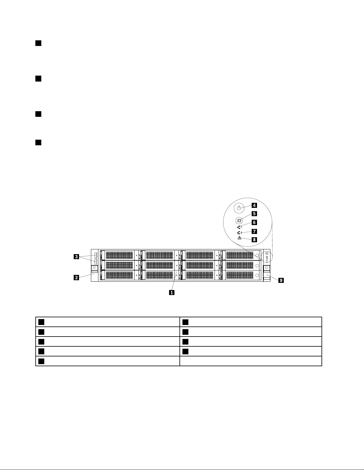
Frontviewofservermodelswith2.5-inchhard-disk-drivebays
Thefollowingillustrationshowsthefrontviewofservermodelswith2.5-inchhard-disk-drivebays.
Figure9.Frontviewofservermodelswith2.5-inchhard-disk-drivebays
12.5-inchhard-disk-drivearea(rightcage)5Rackhandle(left)
22.5-inchhard-disk-drivearea(middlecage)6Diagnosticpanel(variesbymodel)
3Pull-outinformationcard
4Slimopticaldrive(availableinsomemodels)8Rackhandle(right)
12.5-inchhard-disk-drivearea(rightcage)
7Frontpanel
22.5-inchhard-disk-drivearea(middlecage)
Thefrontofservermodelswith2.5-inchhard-disk-drivebaysconsistsofthreecages:
•Theleftcageconsistsofthefrontpanelboard,thefrontVGADB-15connector,thediagnosticmodule,
thepull-outinformationcard,andtheslimopticaldrivebay.
•Themiddlecageconsistsofthenumber0tonumber7hard-disk-drivebays.Thereiseithera2.5-inch
hot-swapharddiskdriveora2.5-inchdummyhard-disk-drivetrayinstalledineachbay.
•Therightcageconsistsofthenumber8tonumber15hard-disk-drivebays.Thereiseithera2.5-inch
hot-swapharddiskdriveora2.5-inchdummyhard-disk-drivetrayinstalledineachbay.Iftheserver
supportsuptoeightharddiskdrives,therewillbeanEMI-protectivepanelthatcoverstherightcage
asawhole.
Figure10.RightcagewithanEMI-protectivepanel
Note:Thehard-disk-drivebaynumber(0-15)ismarkedaboveeach2.5-inchhard-disk-drivebayonthe
frontbezel.
3Pull-outinformationcard
Themachinetype,model,andserialnumberlabeloftheserverisattachedonthepull-outinformationcard.
See“Machinetype,model,andserialnumberlabel”onpage14
.
Chapter3.Productoverview21
Page 34

4Slimopticaldrive
ID
SomeservermodelscomewithaslimSATAopticaldrive.
5Rackhandle(left)
8Rackhandle(right)
Ifyourserverisinstalledinarackcabinet,youcanusetherackhandlestohelpyouslidetheserverout
oftherackcabinet;orusetherackhandlesandscrewstosecuretheserverintherackcabinetsothat
theservercannotslideout,especiallyinvibration-proneareas.Formoreinformation,refertotheRack
InstallationInstructionsthatcomeswithyourserver.
6Diagnosticpanel
Thediagnosticpanelvariesbymodel.Fordetailedinformation,see“Diagnosticmodule”onpage24.
7Frontpanel
Fordetailedinformationaboutthecontrols,connectors,andstatusLEDsonthefrontpanel,see“Front
panel”onpage22.
Frontpanel
Thistopicappliesonlytothefollowingservermodels:
•Servermodelswitheight3.5-inchhard-disk-drivebays
•Servermodelswith2.5-inchhard-disk-drivebays
Forservermodelswithtwelve3.5-inchhard-disk-drivebays,thefrontUSBconnectorsareintegratedinto
theleftrackhandle;andthefrontcontrolsandLEDsareintegratedintotherightrackhandle.See“Front
viewofservermodelswithtwelve3.5-inchhard-disk-drivebays”onpage18fordetailedinformation.
Thefollowingillustrationshowsthecontrols,connectors,andLEDsonthefrontpaneloftheserver.Tolocate
thefrontpanel,see“Frontviewofservermodelswitheight3.5-inchhard-disk-drivebays”onpage17and
“Frontviewofservermodelswith2.5-inchhard-disk-drivebays”onpage21.
Figure11.Frontpanel
1PowerbuttonwithpowerstatusLED
2IDbuttonwithIDLED
3NIC1statusLED7VGADB-15connector
4NIC2statusLED
5SystemerrorLED
6FrontUSBconnectors(2)
22ThinkServerRD440UserGuideandHardwareMaintenanceManual
Page 35

1PowerbuttonwithpowerstatusLED
Youcanpressthepowerbuttontoturnontheserverwhenyoufinishsettinguptheserver.Youalsocan
holdthepowerbuttonforseveralsecondstoturnofftheserverifyoucannotturnofftheserverfromthe
operatingsystem.SeeChapter4“Turningonandturningofftheserver”onpage61
.ThepowerstatusLED
helpsyoutodeterminethecurrentpowerstatus.
PowerstatusLED
Blinking
2IDbuttonwithIDLED
OnGreen
Off
Color
Theserverison.
None
GreenTheserverisinACPIS1mode,whichalsoisknown
Theserverisoff.
asPowerOnSuspend(POS)mode.Inthismode,
themicroprocessorsarenotworkingwhileother
hardwaredevicesarestillworking.
Description
WhenyoupresstheIDbuttononthefrontpanel,theIDLEDsonboththefrontandrearoftheserverare
littohelpyoulocatetheserveramongotherservers.YoualsocanturnontheIDLEDsusingaremote
managementprogramforserverpresencedetection.
3NIC1statusLED
4NIC2statusLED
IDLED
On
Off
Color
Blue
None
Theserverisidentified.
TheIDLEDisnotinuseortheserverisnotidentified.
Description
TheNIC1statusLEDindicatestheLANstatusfortheEthernetconnector1ontherearoftheserver.
TheNIC2statusLEDindicatestheLANstatusfortheEthernetconnector2ontherearoftheserver.
NICstatusLEDColor
OnGreen
Off
Blinking
TheserverisconnectedtoaLAN.
None
Green
TheserverisdisconnectedfromaLAN.
TheLANisconnectedandactive.
Description
Chapter3.Productoverview23
Page 36

5SystemerrorLED
ThesystemerrorLEDhelpsyoutodetermineifthereareanysystemerrors.
•Off:Theserverisoffortheserverisonandworkingcorrectly.
•Amber:Theserverhaspotentialsystemerrors.Checktheinformationinthefollowingtableforpotential
systemerrorsandcorrespondingsolutions.
Potentialsystemerror(systemerrorLED:amber)Solution
Thetemperatureoftheserverreachedthenon-critical
temperaturethreshold.
Thevoltageoftheserverreachedthenon-criticalvoltage
threshold.
Afanisrunningatlowspeed.
Ahot-swapfanhasbeenremoved.1.Ensurethatthesystemfansareconnectedsecurely
Thepowersupplyhasacriticalerror.
Apowercordhasbeendisconnectedoraredundant
powersupplyhasbeenremoved.
Thesystemisoverheated.
ChecktheBMCforerrorsandcheckthesystemfans.
Replacethesystemboard.
Note:ThisactionmustbeperformedonlybyLenovo
servicepersonnel.SeeChapter8“Gettinginformation,
help,andservice”onpage209
Checkthesystemfans.
tothesystemboard.
2.Reinstalltheremovedfanorinstallanewfanto
replacetheremovedfan.
ChecktheBMCfordetailedinformation.
1.Ensurethatthepowersuppliesareinstalledsecurely.
2.Ensurethatthepowercordsareconnectedsecurely
tothepowersupplies.
3.Installanewpowersupplytoreplacetheremoved
one.
ChecktheBMCforerrorsandthencheckthesystem
fans.
.
6FrontUSBconnectors
UsedtoattachaUSB-compatibledevice,suchasaUSBkeyboard,mouse,scanner,orprinter.Ifyou
havemorethansixUSBdevices,youcanpurchaseaUSBhub,whichyoucanusetoconnectadditional
USBdevices.
7VGADB-15connector
UsedtoattachaVGA-compatiblevideodevice,suchasaVGAmonitor.
Diagnosticmodule
Thistopicappliesonlytothefollowingservermodels:
•Servermodelswitheight3.5-inchhard-disk-drivebays
•Servermodelswith2.5-inchhard-disk-drivebays
ThistopicprovidesinformationaboutthediagnosticmoduleandthediagnosticLEDsonthepanelofthe
module.T olocatethediagnosticpanel,see“Frontviewoftheserver”onpage16
Someservermodelscomewithoneofthefollowingdiagnosticmodules:
•IntelligentDiagnosticsModule(IDM)
.
24ThinkServerRD440UserGuideandHardwareMaintenanceManual
Page 37

•IntelligentDiagnosticsModulePremium(IDMPremium)
ManyerrorsarefirstindicatedbyaliterrorLEDonthediagnosticpaneloftheserver.IfanLEDislit,oneor
moreLEDselsewhereintheservermightalsobelittodirectyoutothesourceoftheerror.See“System
boardLEDs”onpage59
.
IntelligentDiagnosticsModule
TheIntelligentDiagnosticsModule(IDM)isavailableinsomemodelstoprovidebasicdiagnosticfunctions.
ThefollowingillustrationshowsthediagnosticLEDsontheIDMpanel.
Figure12.IDMpanel
•WhenthepowersupplyerrorLEDorsystemfanerrorLEDisoff,itindicatesthatthepowersupplyor
systemfanisworkingcorrectly.WhentheambienttemperaturelimitLED,memorymodulestatusLED,
ormicroprocessorstatusLEDisoff,itindicatesthattheserver,memorymodule,ormicroprocessor
isoperatingatanormaltemperature.
•WhenoneerrorLEDislitinamber,itindicatespotentialerrors.Checktheinformationinthefollowing
tableforpotentialerrorsandcorrespondingsolutions.
Table1.Potentialerrorsandcorrespondingsolutions
LED
1Powersupplyerror
LED
2Ambienttemperature
limitLED
3SystemfanerrorLEDSolidon(amber)Oneormoresystemfansare
Status
Solidon(amber)
Solidon(amber)
Thepowersupplyislikelytofail
orhasfailed.
Theambienttemperatureisbelow
7°C(44.6°F)orover40°C(104°F).
runningatlowspeedorhave
beenremoved.
Potentialerror
Solution
ChecktheBMCforerrorsand
runthediagnosticprograms.See
“Usingadiagnosticprogram”on
page204
Note:T oidentifythefailingpower
supply,checkthestatusLED
nearthepowercordconnector
ontheredundantpowersupply.
ChecktheBMCforerrorsand
runthediagnosticprograms.See
“Usingadiagnosticprogram”on
page204
ChecktheBMCforerrorsand
runthediagnosticprograms.See
“Usingadiagnosticprogram”on
page204
Note:Toidentifythefailing
systemfans,checkthestatus
LEDsonthesystemboard.See
“SystemboardLEDs”onpage
59
.
.
.
.
Chapter3.Productoverview25
Page 38

Table1.Potentialerrorsandcorrespondingsolutions(continued)
Mem 1
PSU 1 2
Mem 2
1 2 3 4 5 6
CPU 1 2
1 2 3 4 5 6
Temp
1 2 3 5 6
4Memorymodule
statusLED
LED
Status
Solidon(amber)Oneormorememorymodules
areoverheated.
Potentialerror
ChecktheBMCforerrorsand
runthediagnosticprograms.See
“Usingadiagnosticprogram”on
.
.
5Microprocessor
statusLED(alsoknown
asCPUerrorLED)
page204
Solidon(amber)
Themicroprocessorsare
overheated.
ChecktheBMCforerrorsand
runthediagnosticprograms.See
“Usingadiagnosticprogram”on
page204
IntelligentDiagnosticsModulePremium
TheIntelligentDiagnosticsModulePremium(IDMPremium)isavailableinsomemodelstoprovideadvanced
diagnosticfunctions.ThefollowingillustrationshowsthediagnosticLEDsontheIDMPremiumpanel.
Solution
Figure13.IDMPremiumpanel
1SystemfanerrorLEDs
2CPU1DIMMstatusLEDs
3CPU2DIMMstatusLEDs
4AmbienttemperaturelimitLED
5MicroprocessorstatusLEDs
6PowersupplyerrorLEDs
26ThinkServerRD440UserGuideandHardwareMaintenanceManual
Page 39

1SystemfanerrorLEDs
ID
0 1 2 3 4 5 6 7 8 9 10 11 12 13 14 15
PSU
Mem
CPU
ThesystemfanerrorLEDshelpyoutodetermineifthereareanysystemfanerrors.
Status
Solidoff
Thesystemfansareoperatingcorrectly.
Solidon(amber)Oneormoresystemfansarerunningatlow
speedorhavebeenremoved.
DescriptionAction
ChecktheBMCforerrorsandrunthe
diagnosticprograms.See“Usinga
diagnosticprogram”onpage204
Note:Toidentifythefailingsystemfans,
checkthestatusLEDsonthesystemboard.
See“SystemboardLEDs”onpage59
Thefollowingillustrationshowsthesystemfansandtheirnumbers.
Notes:
•Dependingonthemodel,yourservermightlookslightlydifferentfromtheillustration.
•Yourserverhasfivesystemfans.Thecallout
4indicatesadummysystemfan.
.
.
Figure14.Systemfans
Chapter3.Productoverview27
Page 40

2CPU1DIMMstatusLEDs
3CPU2DIMMstatusLEDs
TheDIMMstatusLEDshelpyoutodetermineifthereareanymemorymoduleerrors.
DescriptionAction
Solidoff
Solidon(amber)
Status
Thememorymodulesareoperatingata
normaltemperature.
WhenaDIMMstatusLEDislitinamber,it
indicatesthatthecorrespondingmemory
moduleisoverheated.
Thefollowingillustrationshowsthememorymodulesandtheirnumbers.
ChecktheBMCforerrorsandrunthe
diagnosticprograms.See“Usinga
diagnosticprogram”onpage204
.
Figure15.DIMMstatusLEDsandDIMMs
4AmbienttemperaturelimitLED
TheambienttemperaturelimitLEDhelpsyoutodetermineiftheserverisrunningatanormaltemperature.
Status
Solidoff
Solidon(amber)Theambienttemperatureisbelow7°C
Theserverisrunningatanormal
temperature.
(44.6°F)orover40°C(104°F).
DescriptionAction
ChecktheBMCforerrorsandrunthe
diagnosticprograms.See“Usinga
diagnosticprogram”onpage204
.
28ThinkServerRD440UserGuideandHardwareMaintenanceManual
Page 41

5MicroprocessorstatusLEDs(alsoknownasCPUstatusLEDs)
ThemicroprocessorstatusLEDhelpsyoutodetermineifthemicroprocessorisrunningatanormal
temperature.
Status
Solidoff
Solidon(amber)
6PowersupplyerrorLEDs
Themicroprocessorsareoperatingata
normaltemperature.
Themicroprocessorsareoverheated.
DescriptionAction
ChecktheBMCforerrorsandrunthe
diagnosticprograms.See“Usinga
diagnosticprogram”onpage204
.
ThepowersupplyerrorLEDhelpsyoutodetermineifthepowersupplyisworkingcorrectly.
DescriptionAction
ChecktheBMCforerrorsandrunthe
diagnosticprograms.See“Usinga
diagnosticprogram”onpage204.
Note:Toidentifythefailingpowersupply,
checkthepowersupplyerrorLEDsonthe
IDMPremiumpanel.
Solidoff
Solidon(amber)
Status
Thepowersupplyisworkingcorrectly.
Thepowersupplyislikelytofailorhasfailed.
Rearviewoftheserver
Thistopicprovidesinformationtohelpyoulocatetheconnectorsandcomponentsontherearofyourserver.
Expansioncardinstallationguidelines
BeforeinstallinganysupportedexpansioncardintoaPCIExpresscardslot,ensurethatyouobserve
thefollowingguidelines:
•OnlyoneHostBusAdaptercanbeinstalled.
•IftheThinkServerRAID300isavailable,yourserverdoesnotsupportHostBusAdapters.
•IfaRAID500Adapter,aRAID700Adapter,oraRAID710Adapterisinstalled,yourserversupportsup
tothreeEthernetcardsandoneHostBusAdapter.However,ifanI350-T4Ethernetcardisinstalled,
yourserverdoesnotsupportHostBusAdapters.
Chapter3.Productoverview29
Page 42

Thefollowingillustrationshowstherearviewoftheserver.
Figure16.Rearviewoftheserver
1Hot-swapredundantpowersupply2(availablein
7VGADB-15connector
somemodels)
2Hot-swapredundantpowersupply1
3PCIExpresscardareaforcardsontherisercard
8Ethernetconnector1(RJ-45)
9Ethernetconnector0forsystemmanagement(RJ-45)
assembly2
4PCIExpresscardareaforcardsontherisercard
10Serialconnector
assembly1
5Ethernetconnector2(RJ-45)
6FourUSBconnectors
1Hot-swapredundantpowersupply2(availableinsomemodels)
2Hot-swapredundantpowersupply1
11IDLED
Thehot-swapredundantpowersupplieshelpyouavoidsignificantinterruptiontotheoperationofthe
systemwhenapowersupplyfails.Youcanpurchaseahot-swapredundantpowersupplyoptionfrom
Lenovoandinstallthepowersupplytoprovidepowerredundancywithoutturningofftheserver.
Oneachhot-swapredundantpowersupply,thereisastatusLEDnearthepowercordconnector.Whenthe
LEDislitingreen,itindicatesthatthehot-swapredundantpowersupplyisworkingcorrectly.WhentheLED
islitinamber,itindicatesthatthehot-swapredundantpowersupplyislikelytofailorhasfailed.
30ThinkServerRD440UserGuideandHardwareMaintenanceManual
Page 43

3PCIExpresscardareaforcardsontherisercardassembly2
TherearethreePCIExpresscardslotsontherisercardassembly2forinstallingEthernetcardsorother
supportedPCIExpresscards.
Figure17.Risercardassembly2
PCIExpresscardslot
1
2
3
Physicallink
width
x16x8,x4,x2,x1
x8x8,x4,x2,x1
x8x4,x2,x1
Negotiablelink
width
Supportedcardlengthand
height
Half-length,full-heightcard
Half-length,full-heightcard
Low-profilecard
Notes:
•Theslot
withonemicroprocessor,theslot
1andslot2aresupportedonlyinservermodelswithtwomicroprocessors.Forservermodels
1andslot2arecovered.Ifyouinstallthesecondmicroprocessor
intheserver,youneedtoremovethecoversthatprotecttheslot1andslot2beforeinstallingany
supportedcardsintotheslots.
•Youalsocaninstallaconvergednetworkadapter(CNA)intoaPCIExpresscardslot.
Chapter3.Productoverview31
Page 44

4PCIExpresscardareaforcardsontherisercardassembly1
TherearethreePCIExpresscardslotsontherisercardassembly1.
Figure18.Risercardassembly1
PCIExpresscardslot
1
2
3
Physicallink
width
x8x4,x2,x1
x8x8,x4,x2,x1
x16x8,x4,x2,x1
Negotiablelinkwidth
Supportedcardlengthandheight
Half-length,full-heightcard
Half-length,full-heightcard
Half-length,full-heightcard
Notes:
•ForaRAIDcard,itmustbeinstalledintotheslot3ontherisercardassembly1.Foranexpander
card,itmustbeinstalledintotheslot1ontherisercardassembly1.YoualsocaninstallaCNAcard
intoaPCIExpresscardslot.
•IfaThinkServerHBAisavailable,refertoitsuserguidefordetailedinformation.Theuserguideis
availablefordownloadat:
http://www.lenovo.com/UserManuals
32ThinkServerRD440UserGuideandHardwareMaintenanceManual
Page 45

589Ethernetconnectors(RJ-45)
UsedtoattachanEthernetcableforaLAN.EachEthernetconnectorhastwostatusLEDstohelpyou
identifytheEthernetconnectivity,activity,andconnectionspeed.
Note:TheEthernetconnector0(callout9)markedwith“MGMT”isforsystemmanagementbydefault.
However,youalsocansettheEthernetconnector1or2forsystemmanagementuseintheSetupUtility
program.See“SettingthemodeoftheEthernetconnectors”onpage69
Figure19.EthernetstatusLEDs
.
EthernetstatusLED
1Left
2Right
6USBconnectors
ColorStatus
Amber
GreenOn
None
GreenOn
None
Green
On
Off
Off
BlinkingTheLANisconnectedandactive.
Theconnectionspeedis1000Mbps.
Theconnectionspeedis100Mbps.
Theconnectionspeedis10Mbps.
TheserverisconnectedtoaLAN.
TheserverisdisconnectedfromaLAN.
Description
UsedtoattachaUSB-compatibledevice,suchasaUSBkeyboard,mouse,scanner,orprinter.Ifyou
havemorethansixUSBdevices,youcanpurchaseaUSBhub,whichyoucanusetoconnectadditional
USBdevices.
7VGADB-15connector
UsedtoattachaVGA-compatiblevideodevice,suchasaVGAmonitor.
10Serialconnector
Usedtoattachadevicethatusesa9-pinserialconnector.
11IDLED
WhenyoupresstheIDbuttononthefrontoftheserver,theIDLEDsonboththefrontandrearoftheserver
arelittohelpyoulocatetheserveramongotherservers.YoualsocanturnontheIDLEDsusingaremote
managementprogramforserverpresencedetection.
IDLED
On
Off
Color
Blue
None
Theserverisidentified.
TheIDLEDisnotinuseortheserverisnotidentified.
Description
Chapter3.Productoverview33
Page 46

Servercomponents
Thistopicprovidesinformationtohelpyoulocatethecomponentsofyourserver.Formoreinformation
aboutmajorcomponents,seetherelatedtopicsin“Locations”onpage14
Toremovetheservercoverandgainaccesstotheinsideoftheserver,see“Removingtheservercover”
onpage87.
Thechassisconfigurationvariesbymodel.Thefollowingillustrationsshowthethreemainchassis
configurationsbasedonthesupportedharddiskdrives.
•“Componentsofservermodelswitheight3.5-inchhard-disk-drivebays”onpage35
•“Componentsofservermodelswithtwelve3.5-inchhard-disk-drivebays”onpage36
•“Componentsofservermodelswith2.5-inchhard-disk-drivebays”onpage37
Note:Dependingonthemodel,yourservermightlookslightlydifferentfromtheillustrationsinthistopic.
.
34ThinkServerRD440UserGuideandHardwareMaintenanceManual
Page 47

Componentsofservermodelswitheight3.5-inchhard-disk-drivebays
MEM 1
PSU 1 2
1 2 3 4 5 6 7 8
MEM 2
1 2 3 4 5 6 7 8 9 10
CPU 1 2
1 2 3 4 5 6 7 8 9 10
ID
PSU
Mem
CPU
Figure20.Componentsofservermodelswitheight3.5-inchhard-disk-drivebays
1Coolingshroud
2Powersupplycoolingshroud
3Risercardassembly214Frontpanelboard
4Oneortwohot-swapredundantpowersupplies
5PCIExpresscards(availableinsomemodels)16Systemfans(5)
6Heatsinkswithmicroprocessorsunderneath
7Slimopticaldrive(availableinsomemodels)18CPU2DIMMs(varybymodel)
8Rackhandle(right)19Systemboard
93.5-inchhard-disk-drivearea
10Diagnosticmodule(variesbymodel)21PCIExpresscards(availableinsomemodels)
11VGADB-15connector
12Pull-outinformationcard
13Rackhandle(left)
15Hot-swaphard-disk-drivebackplane
17CPU1DIMMs(varybymodel)
20Coin-cellbattery
22Risercardassembly1
Chapter3.Productoverview35
Page 48

Componentsofservermodelswithtwelve3.5-inchhard-disk-drivebays
ID
Figure21.Componentsofservermodelswithtwelve3.5-inchhard-disk-drivebays
1Coolingshroud
2Powersupplycoolingshroud
3Risercardassembly2
4Oneortwohot-swapredundantpowersupplies13CPU2DIMMs(varybymodel)
5PCIExpresscards(availableinsomemodels)14Systemboard
6Heatsinkswithmicroprocessorsunderneath
7Rackhandle(right)withfrontcontrolsandLEDs
83.5-inchhard-disk-drivearea17RAIDcard
9Rackhandle(left)withfrontUSBconnectors
10Hot-swaphard-disk-drivebackplane
11Systemfans(5)
12CPU1DIMMs(varybymodel)
15Coin-cellbattery
16Expandercard
18Risercardassembly1
36ThinkServerRD440UserGuideandHardwareMaintenanceManual
Page 49

Componentsofservermodelswith2.5-inchhard-disk-drivebays
ID
PSU
Mem
CPU
0 1 2 3 4 5 6 7 8 9 10 11 12 13 14 15
Figure22.Componentsofservermodelswith2.5-inchhard-disk-drivebays
1Coolingshroud13Slimopticaldrive(availableinsomemodels)
2Powersupplycoolingshroud
3Risercardassembly2
4Oneortwohot-swapredundantpowersupplies
14Diagnosticmodule(variesbymodel)
15Rackhandle(left)
16Frontpanelboard
5PCIExpresscards(availableinsomemodels)17Systemfans(5)
6Heatsinkswithmicroprocessorsunderneath
7Hot-swaphard-disk-drivebackplanes
18CPU1DIMMs(varybymodel)
19CPU2DIMMs(varybymodel)
8Rackhandle(right)20Systemboard
92.5-inchhard-disk-drivearea(rightcage)21Coin-cellbattery
102.5-inchhard-disk-drivearea(middlecage)22PCIExpresscards(availableinsomemodels)
11Pull-outinformationcard
23Risercardassembly1
12VGADB-15connector
CRUidentification
CRUsarepartsthatcanbeupgradedorreplacedbythecustomer.IfaCRUisdeterminedtobedefective
duringthewarrantyperiod,areplacementCRUwillbeprovidedtothecustomer.Customersareresponsible
forinstallingtheself-serviceCRUsforthisproduct.Customersalsocaninstalloptional-serviceCRUs,which
Chapter3.Productoverview37
Page 50

mightrequiresometechnicalskillsortools,orrequestthatatechnicianinstalltheoptional-serviceCRU
underthetermsoftheapplicablewarrantyservicetypeforyourcountryorregion.
Non-CRUsmustbereplacedonlybytrainedservicetechnicians.
ThefollowingtableliststhemajorFRUsinyourserverandtheCRUidentificationinformation.Foracomplete
listingofFRUinformation,suchasFRUpartnumbersandsupportedservermodels,goto:
http:/www.lenovo.com/serviceparts-lookup
Notes:
•BeforeservicingaLenovoproduct,ensurethatyoureadandunderstand“Safetyinformation”onpageiii
•UseonlypartsprovidedbyLenovo.
FRUdescription
Coolingshroud
DiagnosticmoduleNoYes
FrontpanelboardNoYes
HeatsinkYesNo
Hot-swapharddiskdriveYesNo
Hot-swaphard-disk-drivebackplaneNoYes
Hot-swapredundantpowersupplyYesNo
MemorymoduleYesNo
MicroprocessorNoYes
Opticaldrive(availableinsomemodels)
PCIcard(availableinsomemodels)
RackhandlesYesNo
RisercardassemblyYesNo
Systemboard
Coin-cellbattery
Systemfan
ThinkServerManagementModulePremium(availableasanoption)
ThinkServerRAID300UpgradeKeyforAdvancedRAID(availableas
anoption)
ThinkServerRAID500UpgradeKeyforAdvancedRAID(availableas
anoption)
ThinkServerRAID700Battery(availableasanoption)
Self-serviceCRU
YesNo
YesNo
YesNo
NoNo
YesNo
YesNo
YesNo
YesNo
NoYes
NoYes
Optional-service
CRU
.
ThinkServerRAIDSuperCapacitorModule(availableasanoption)
ThinkServerTrustedPlatformModule(availableasanoption)
38ThinkServerRD440UserGuideandHardwareMaintenanceManual
NoYes
YesNo
Page 51

Hot-swaphard-disk-drivestatusLEDs
Eachhot-swapharddiskdrivehastwostatusLEDsonthefront.
Figure23.3.5-inchhot-swaphard-disk-drivestatusLEDs
Figure24.2.5-inchhot-swaphard-disk-drivestatusLEDs
1Hard-disk-driveactivityLED2Hard-disk-driveRAIDstatusLEDDescription
OffOff
On,greenOff
Blinking,green
On,greenBlinkingrapidly(aboutfourflashes
On,greenOn,amber
Blinking,green
Off
persecond),amber
Blinkingslowly(aboutoneflashper
second),amber
Theharddiskdrivehasfailedoris
notpresent.
Theharddiskdriveispresentbutnot
inuse.
Theharddiskdriveisactiveanddata
isbeingtransferred.
TheRAIDcontrollerisidentifyingthe
harddiskdrive.
TheRAIDarrayhasfailedandcannot
berecovered.Y ouneedtorecreate
anarray.
Theharddiskdriveisbeingrebuilt.
Chapter3.Productoverview39
Page 52

RAIDcard
ThistopicprovidesinformationtohelpyoulocatetheconnectorsontheRAIDcardifaRAIDcardinstalled
isinthelongerslotoftherisercardassembly1.
SomeservermodelscomewithaRAIDcardtoprovideadvancedSATA/SAShardwareRAIDfunctions.You
alsocanpurchaseasupportedRAIDcardfromLenovoandinstallitintotheserver.See“Installingor
removingtheRAIDcard”onpage105
Notes:
•TheoptionkitforaRAIDcardisdesignedfordifferenttypesofserversandmightcontainadditional
cablesthatarenotrequiredforyourserver.
•TheservermusthaveaRAIDcardandanexpandercardinstalledtosupportmorethaneighthard
diskdrives.
YourserversupportsthefollowingRAIDcards:
•ThinkServerRAID500Adapter(alsoknownasThinkServer9240-8iRAID0/1Adapter)
•ThinkServerRAID700Adapter(alsoknownasThinkServer9260-8iSASRAIDAdapter)
•ThinkServerRAID710Adapter(alsoknownas9270CV-8iRAIDadapter)
ThinkServerRAID500Adapter(alsoknownasThinkServer9240-8iRAID0/1Adapter)
ThefollowingillustrationshowstheconnectorsontheThinkServerRAID500Adapter.
.
Figure25.ThinkServerRAID500Adapter
1Port03TR500keyconnector
2Port1
1Port0
Usedtoconnectamini-SASsignalcable.See“Connectingthecables”onpage47
2Port1
Usedtoconnectamini-SASsignalcable.See“Connectingthecables”onpage47
3TR500keyconnector
.
.
UsedtoconnectaThinkServerRAID500UpgradeKeyforAdvancedRAID.See“Installingorremovingthe
ThinkServerRAID500UpgradeKeyforAdvancedRAID”onpage108.
40ThinkServerRD440UserGuideandHardwareMaintenanceManual
Page 53

ThinkServerRAID700Adapter(alsoknownasThinkServer9260-8iSASRAIDAdapter)
ThefollowingillustrationshowstheconnectorsontheThinkServerRAID700Adapter.
Figure26.ThinkServerRAID700Adapter
1Ports7-4
2Ports3-0
1Ports7-4
Usedtoconnectamini-SASsignalcable.See“Connectingthecables”onpage47
2Ports3-0
Usedtoconnectamini-SASsignalcable.See“Connectingthecables”onpage47
3ThinkServerRAID700Batteryconnector
3ThinkServerRAID700Batteryconnector
.
.
UsedtoconnectaThinkServerRAID700Battery.See“InstallingorremovingtheThinkServerRAID700
Battery”onpage111.
Chapter3.Productoverview41
Page 54

ThinkServerRAID710Adapter(alsoknownas9270CV-8iRAIDadapter)
ThefollowingillustrationshowstheconnectorsontheThinkServerRAID710Adapter.
Figure27.ThinkServerRAID710Adapter
1Port1
2Port2
1Port1
3ThinkServerRAIDSuperCapacitorModuleconnector
Usedtoconnectamini-SASsignalcable.See“Connectingthecables”onpage47.
2Port2
Usedtoconnectamini-SASsignalcable.See“Connectingthecables”onpage47.
3ThinkServerRAIDSuperCapacitorModuleconnector
UsedtoconnectthecableofaThinkServerRAIDSuperCapacitorModule.See“ReplacingtheThinkServer
RAIDSuperCapacitorModule”onpage163.
Expandercard
Thistopicprovidesinformationtohelpyoulocatetheconnectorsontheexpandercardifyourserverhas
oneinstalledintheshorterslotoftherisercardassembly1.
TheexpandercardworkstogetherwiththeRAIDcardbyexpandingtheportsontheRAIDcardsothat
theservercansupportupto16harddiskdrives.
Note:TheservermusthaveaRAIDcardandanexpandercardinstalledtosupportmorethaneighthard
diskdrives.
42ThinkServerRD440UserGuideandHardwareMaintenanceManual
Page 55

Thefollowingillustrationshowstheconnectorsontheexpandercard.Eachconnectorontheexpander
cardisusedtoconnectamini-SAStomini-SASsignalcable.Fordetailedinformation,see“Connecting
thecables”onpage47
Figure28.Expandercard
1Connector14Connector4
2Connector25Connector5
3Connector36Connector6
.
Hot-swaphard-disk-drivebackplane
Yourservermightcomewithoneofthefollowinghot-swaphard-disk-drivebayandbackplaneconfigurations:
•Eight3.5-inchhard-disk-drivebaysandonebackplane
•Twelve3.5-inchhard-disk-drivebaysandonebackplane
•Eight2.5-inchhard-disk-drivebaysandonebackplane
•Sixteen2.5-inchhard-disk-drivebaysandtwobackplanes
Tolocatethebackplanes,see“Servercomponents”onpage34
Backplaneforservermodelswitheight3.5-inchhard-disk-drivebays
Thistopicprovidesinformationtohelpyoulocatetheconnectorsonthebackplaneforservermodels
witheight3.5-inchhard-disk-drivebays.
.
Chapter3.Productoverview43
Page 56

Thefollowingillustrationsshowtheconnectorsonthebackplaneforservermodelswitheight3.5-inch
hard-disk-drivebays.
Figure29.Frontviewofthebackplaneforservermodelswitheight3.5-inchhard-disk-drivebays
1Slot0fora3.5-inchharddiskdrive5Slot7fora3.5-inchharddiskdrive
2Slot2fora3.5-inchharddiskdrive6Slot5fora3.5-inchharddiskdrive
3Slot4fora3.5-inchharddiskdrive7Slot3fora3.5-inchharddiskdrive
4Slot6fora3.5-inchharddiskdrive8Slot1fora3.5-inchharddiskdrive
Figure30.Rearviewofthebackplaneforservermodelswitheight3.5-inchhard-disk-drivebays
18-pinpowerconnector
28-pinpowerconnector
3Opticaldrivepowerconnector
128-pinpowerconnector
4Mini-SASports4-7
5Mini-SASports0-3
Usedtoconnectapowercabletoprovidepowertothebackplane.
3Opticaldrivepowerconnector
Usedtoconnectthepowercablefortheslimopticaldriveiftheserverhasoneinstalled.
4Mini-SASports4-7
Usedtoconnectthemini-SASconnectorononeendofamini-SAStomini-SASsignalcabletosupportthe
harddiskdrive4toharddiskdrive7.
5Mini-SASports0-3
Usedtoconnectthemini-SASconnectorononeendofamini-SAStomini-SASsignalcabletosupportthe
harddiskdrive0toharddiskdrive3.
44ThinkServerRD440UserGuideandHardwareMaintenanceManual
Page 57

Backplaneforservermodelswithtwelve3.5-inchhard-disk-drivebays
Thistopicprovidesinformationtohelpyoulocatetheconnectorsonthebackplaneforservermodelswith
twelve3.5-inchhard-disk-drivebays.
Thefollowingillustrationsshowtheconnectorsonthebackplaneforservermodelswithtwelve3.5-inch
hard-disk-drivebays.
Figure31.Frontviewofthebackplaneforservermodelswithtwelve3.5-inchhard-disk-drivebays
1Slot0fora3.5-inchharddiskdrive7Slot6fora3.5-inchharddiskdrive
2Slot1fora3.5-inchharddiskdrive8Slot7fora3.5-inchharddiskdrive
3Slot2fora3.5-inchharddiskdrive9Slot8fora3.5-inchharddiskdrive
4Slot3fora3.5-inchharddiskdrive10Slot9fora3.5-inchharddiskdrive
5Slot4fora3.5-inchharddiskdrive11Slot10fora3.5-inchharddiskdrive
6Slot5fora3.5-inchharddiskdrive12Slot11fora3.5-inchharddiskdrive
Figure32.Rearviewofthebackplaneforservermodelswithtwelve3.5-inchhard-disk-drivebays
1Signalcableconnector5Signalcableconnector
2Mini-SASports8-11
3Mini-SASports4-7
4Mini-SASports0-3
1Signalcableconnector
68-pinpowerconnector
78-pinpowerconnector
UsedtoconnectthesignalcableforthefrontcontrolsandLEDsontherightrackhandle.
2Mini-SASports8-11
Usedtoconnectthemini-SASconnectorononeendofamini-SAStomini-SASsignalcabletosupportthe
harddiskdrive8toharddiskdrive11.
Chapter3.Productoverview45
Page 58

3Mini-SASports4-7
Usedtoconnectthemini-SASconnectorononeendofamini-SAStomini-SASsignalcabletosupportthe
harddiskdrive4toharddiskdrive7.
4Mini-SASports0-3
Usedtoconnectthemini-SASconnectorononeendofamini-SAStomini-SASsignalcabletosupportthe
harddiskdrive0toharddiskdrive3.
5Signalcableconnector
UsedtoconnectthesignalcableforthefrontUSBconnectorsontheleftrackhandle.
678-pinpowerconnector
Usedtoconnectapowercabletoprovidepowertothebackplane.
Backplaneforservermodelswith2.5-inchhard-disk-drivebays
Thistopicprovidesinformationtohelpyoulocatetheconnectorsonthebackplaneforservermodelswith
2.5-inchhard-disk-drivebays.
Thefollowingillustrationsshowtheconnectorsonthebackplaneforservermodelswith2.5-inch
hard-disk-drivebays.
Figure33.Frontviewofthebackplaneforservermodelswith2.5-inchhard-disk-drivebays
1Slot0fora2.5-inchharddiskdriveorsolid-state
drive
2Slot1fora2.5-inchharddiskdriveorsolid-state
drive
3Slot2fora2.5-inchharddiskdriveorsolid-state
drive
4Slot3fora2.5-inchharddiskdriveorsolid-state
drive
5Slot4fora2.5-inchharddiskdriveorsolid-statedrive
6Slot5fora2.5-inchharddiskdriveorsolid-statedrive
7Slot6fora2.5-inchharddiskdriveorsolid-statedrive
8Slot7fora2.5-inchharddiskdriveorsolid-statedrive
46ThinkServerRD440UserGuideandHardwareMaintenanceManual
Page 59

Figure34.Rearviewofthebackplaneforservermodelswith2.5-inchhard-disk-drivebays
18-pinpowerconnector
2Mini-SASports4-74Opticaldrivepowerconnector
18-pinpowerconnector
3Mini-SASports0-3
Usedtoconnectapowercabletoprovidepowertothebackplane.
2Mini-SASports4-7
Usedtoconnectthemini-SASconnectorononeendofamini-SAStomini-SASsignalcabletosupport
theharddiskdrive4toharddiskdrive7;ortosupporttheharddiskdrive12toharddiskdrive15ifthe
backplaneisforharddiskdrivesintherightcageoftheserver.
3Mini-SASports0-3
Usedtoconnectthemini-SASconnectorononeendofamini-SAStomini-SASsignalcabletosupportthe
harddiskdrive0toharddiskdrive3;ortosupporttheharddiskdrive8toharddiskdrive11ifthebackplane
isforharddiskdrivesintherightcageoftheserver.
4Opticaldrivepowerconnector
Usedtoconnectthepowercablefortheslimopticaldriveiftheserverhasoneinstalled.
Connectingthecables
Thistopicprovidesinstructionsonhowtoconnectthemini-SAStomini-SASsignalcables.Thistopic
containsthefollowingitems:
•“ConnectingcablesfromtheRAIDcardtothebackplane”onpage47
•“ConnectingcablesfromtheRAIDcardtotheexpandercard,andthenfromtheexpandercardto
thebackplanes”onpage48
•“Connectingcablesfromthesystemboardtothebackplane”onpage51
ConnectingcablesfromtheRAIDcardtothebackplane
IfyourserverhasasupportedRAIDcardinstalled,youcanconnectcablesfromtheRAIDcardtothe
backplanetosupportuptoeightharddiskdrivesandadvancedhardwareRAIDfunctions.
Chapter3.Productoverview47
Page 60

Note:TheoptionkitforaRAIDcardisdesignedfordifferenttypesofserversandmightcontainadditional
cablesthatarenotrequiredforyourserver.
Figure35.ConnectingcablesfromtheRAIDcardtothebackplane
ToconnectcablesfromtheRAIDcardtothebackplane,dooneofthefollowingdependingonthetypeof
yourRAIDcard:
•IfyouareusingaThinkServerRAID500Adapter,dothefollowing:
1.Usethemini-SAStomini-SASsignalcable.Connectthemini-SASconnector1totheport0onthe
RAIDcard.Then,connectthemini-SASconnector2tothemini-SASports0-3onthebackplane.
2.Ifyourserverhasmorethanfourharddiskdrivesinstalled,usetheothermini-SAStomini-SAS
signalcable.Connectthemini-SASconnector3totheport1ontheRAIDcard.Then,connectthe
mini-SASconnector4tothemini-SASports4-7onthebackplane.
•IfyouareusingaThinkServerRAID700Adapter,dothefollowing:
1.Useonemini-SAStomini-SASsignalcable.Connectthemini-SASconnector3totheports3-0on
theRAIDcard.Then,connectthemini-SASconnector4tothemini-SASports0-3onthebackplane.
2.Ifyourserverhasmorethanfourharddiskdrivesinstalled,usetheothermini-SAStomini-SASsignal
cable.Connectthemini-SASconnector1totheports7-4ontheRAIDcard.Then,connectthe
mini-SASconnector
2tothemini-SASports4-7onthebackplane.
•IfyouareusingaThinkServerRAID710Adapter,dothefollowing:
1.Usethemini-SAStomini-SASsignalcable.Connectthemini-SASconnector1totheport1onthe
RAIDcard.Then,connectthemini-SASconnector
2tothemini-SASports0-3onthebackplane.
2.Ifyourserverhasmorethanfourharddiskdrivesinstalled,usetheothermini-SAStomini-SAS
signalcable.Connectthemini-SASconnector
3totheport2ontheRAIDcard.Then,connectthe
mini-SASconnector4tothemini-SASports4-7onthebackplane.
Refertothefollowingtopicsforinformationabouttheconnectorlocationsandthepowercableconnections:
•“Hot-swaphard-disk-drivebackplane”onpage43
•“RAIDcard”onpage40
•“Systemboardcomponents”onpage52
ConnectingcablesfromtheRAIDcardtotheexpandercard,andthenfromthe
expandercardtothebackplanes
Tosupportmorethaneightanduptotwelve3.5-inchharddiskdrivesoruptosixteen2.5-inchharddisk
drives,yourservermusthaveasupportedRAIDcardandanexpandercardinstalled.Youneedtoconnect
cablesfromtheRAIDcardtotheexpandercard,andthenfromtheexpandercardtothebackplanes.
48ThinkServerRD440UserGuideandHardwareMaintenanceManual
Page 61

UsethefollowinginstructionstoconnectcablesfromtheRAIDcardtotheexpandercardfirst:
•IfyouareusingaThinkServerRAID500Adapter,dothefollowing:
1.Useamini-SAStomini-SASsignalcableandconnectthemini-SASconnectorononeendofthe
cabletotheport0ontheThinkServerRAID500Adapter.Then,connectthemini-SASconnectoron
theotherendofthecabletotheconnector1ontheexpandercard.
2.Useanothermini-SAStomini-SASsignalcableandconnectthemini-SASconnectorononeendof
thecabletotheport1ontheThinkServerRAID500Adapter.Then,connectthemini-SASconnector
ontheotherendofthecabletotheconnector2ontheexpandercard.
•IfyouareusingaThinkServerRAID700Adapter,dothefollowing:
1.Useamini-SAStomini-SASsignalcableandconnectthemini-SASconnectorononeendofthe
cabletotheports3-0ontheThinkServerRAID700Adapter.Then,connectthemini-SASconnector
ontheotherendofthecabletotheconnector1ontheexpandercard.
2.Useanothermini-SAStomini-SASsignalcableandconnectthemini-SASconnectorononeend
ofthecabletotheports7-4ontheThinkServerRAID700Adapter.Then,connectthemini-SAS
connectorontheotherendofthecabletotheconnector2ontheexpandercard.
•IfyouareusingaThinkServerRAID710Adapter,dothefollowing:
1.Useamini-SAStomini-SASsignalcableandconnectthemini-SASconnectorononeendofthe
cabletotheports1ontheThinkServerRAID710Adapter.Then,connectthemini-SASconnectoron
theotherendofthecabletotheconnector1ontheexpandercard.
2.Useanothermini-SAStomini-SASsignalcableandconnectthemini-SASconnectorononeendof
thecabletotheports2ontheThinkServerRAID710Adapter.Then,connectthemini-SASconnector
ontheotherendofthecabletotheconnector2ontheexpandercard.
RefertothefollowingtopicsforinformationabouttheconnectorlocationsontheRAIDcardandexpander
card:
•“RAIDcard”onpage40
•“Expandercard”onpage42
Chapter3.Productoverview49
Page 62

Usethefollowinginstructionstoconnectcablesfromtheexpandercardtothebackplanesfor2.5-inch
harddiskdrives:
1.Forharddiskdrive0toharddiskdrive3,useamini-SAStomini-SASsignalcableandconnectthe
mini-SASconnector
1ononeendofthecabletotheconnector3ontheexpandercard.Then,connect
themini-SASconnectorontheotherendofthecabletothemini-SASports0-3onthebackplane
for2.5-inchharddiskdrivesinthemiddlecage.
2.Forharddiskdrive4toharddiskdrive7,useamini-SAStomini-SASsignalcableandconnectthe
mini-SASconnector
2ononeendofthecabletotheconnector4ontheexpandercard.Then,connect
themini-SASconnectorontheotherendofthecabletothemini-SASports4-7onthebackplane
for2.5-inchharddiskdrivesinthemiddlecage.
3.Forharddiskdrive8toharddiskdrive11,useamini-SAStomini-SASsignalcableandconnectthe
mini-SASconnector3ononeendofthecabletotheconnector5ontheexpandercard.Then,connect
themini-SASconnectorontheotherendofthecabletothemini-SASports0-3onthebackplane
for2.5-inchharddiskdrivesintherightcage.
4.Ifyourserverhasmorethan12harddiskdrivesinstalled,forharddiskdrive12toharddiskdrive15,
useamini-SAStomini-SASsignalcableandconnectthemini-SASconnector4ononeendofthe
cabletotheconnector6ontheexpandercard.Then,connectthemini-SASconnectorontheotherend
ofthecabletothemini-SASports4-7onthebackplanefor2.5-inchharddiskdrivesintherightcage.
Figure36.Connectingcablesfromtheexpandercardtothebackplanesfor2.5-inchharddiskdrives
Refertothefollowingtopicsforinformationabouttheconnectorlocationsandthepowercableconnections:
•“Hot-swaphard-disk-drivebackplane”onpage43
•“Expandercard”onpage42
•“Systemboardcomponents”onpage52
50ThinkServerRD440UserGuideandHardwareMaintenanceManual
Page 63

Usethefollowinginstructionstoconnectcablesfromtheexpandercardtothebackplanefortwelve3.5-inch
harddiskdrives:
1.Forharddiskdrive0toharddiskdrive3,useamini-SAStomini-SASsignalcableandconnectthe
mini-SASconnector
1ononeendofthecabletotheconnector3ontheexpandercard.Then,connect
themini-SASconnectorontheotherendofthecabletothemini-SASports0-3onthebackplane
fortwelve3.5-inchharddiskdrives.
2.Forharddiskdrive4toharddiskdrive7,useamini-SAStomini-SASsignalcableandconnectthe
mini-SASconnector
2ononeendofthecabletotheconnector4ontheexpandercard.Then,connect
themini-SASconnectorontheotherendofthecabletothemini-SASports4-7onthebackplane
fortwelve3.5-inchharddiskdrives.
3.Forharddiskdrive8toharddiskdrive11,useamini-SAStomini-SASsignalcableandconnectthe
mini-SASconnector3ononeendofthecabletotheconnector5ontheexpandercard.Then,connect
themini-SASconnectorontheotherendofthecabletothemini-SASports8-11onthebackplane
fortwelve3.5-inchharddiskdrives.
Figure37.Connectingcablesfromtheexpandercardtothebackplanefortwelve3.5-inchharddiskdrives
Refertothefollowingtopicsforinformationabouttheconnectorlocationsandthepowercableconnections:
•“Hot-swaphard-disk-drivebackplane”onpage43
•“Expandercard”onpage42
•“Systemboardcomponents”onpage52
Connectingcablesfromthesystemboardtothebackplane
YourserverhastwoSASconnectorsonthesystemboardtosupportuptoeightharddiskdrives.
Ifyouconnectthemini-SAStomini-SASsignalcablesfromthesystemboardtothebackplane,youcan
configureRAIDfortheharddiskdrivesusingthefunctionsoftheThinkServerRAID300(alsoknownasthe
onboardSASsoftwareRAID).
Usethefollowinginstructionstoconnectcablesfromthesystemboardtothebackplane:
1.Forharddiskdrive0toharddiskdrive3,useamini-SAStomini-SASsignalcableandconnectthe
mini-SASconnectorononeendofthecabletotheSASconnector0-3onthesystemboard.Then,
Chapter3.Productoverview51
Page 64

connectthemini-SASconnectorontheotherendofthecabletothemini-SASports0-3onthe
backplane.
2.Ifyourserverhasmorethanfourharddiskdrivesinstalled,forharddiskdrive4toharddiskdrive7,use
anothermini-SAStomini-SASsignalcableandconnectthemini-SASconnectorononeendofthe
cabletotheSASconnector4-7onthesystemboard.Then,connectthemini-SASconnectoronthe
otherendofthecabletothemini-SASports4-7onthebackplane.
Refertothefollowingtopicsforinformationabouttheconnectorlocationsandthepowercableconnections:
•“Hot-swaphard-disk-drivebackplane”onpage43
•“Systemboardcomponents”onpage52
Systemboardcomponents
Thefollowingillustrationshowsthecomponentlocationsonthesystemboard.
Figure38.Systemboardcomponents
1Frontpanelconnector17Risercardassembly1slot
2InternalUSBconnector1
3InternalUSBconnector2
4Diagnosticmoduleconnector20Redundantpowersupplyconnector2
5FrontVGAconnector
6SATAconnector0
18Risercardassembly2slot
19Redundantpowersupplyconnector1
21Backplanepowerconnector1
22Backplanepowerconnector2
52ThinkServerRD440UserGuideandHardwareMaintenanceManual
Page 65

7SASconnector4-723Systemfan6connector
8SASconnector0-3
9Coin-cellbattery25Systemfan5connector
10PlatformControllerHub(PCH)26Memoryslots(6)
11InternalUSBTypeAconnector227Systemfan3connector
12TMMPremiumconnector28Microprocessorsocket1
13InternalUSBTypeAconnector129Systemfan2connector
14TPMconnector
15iButtonsocket
16ThinkServerManagementModule
1Frontpanelconnector
24Microprocessorsocket2
30Memoryslots(6)
31Systemfan1connector
Usedtoconnectthefrontpanelcableifyourserverhasafrontpanelboardinstalled.
2InternalUSBconnector1
UsedtoconnectthefrontpanelUSBcableifyourserverhasafrontpanelboardinstalled.
3InternalUSBconnector2
Reservedforthemanufacturer.
4Diagnosticmoduleconnector
Usedtoconnectthecableofthediagnosticmoduleifyourserverhasadiagnosticmoduleinstalled.
5FrontVGAconnector
UsedtoconnectthecableoftheVGADB-15connectoronthefrontpanelofsomeservermodels.
6SA T Aconnector0
Usedtoconnectthesignalcableoftheslimopticaldriveifyourserverhasaslimopticaldriveinstalled.
7SASconnector4-7
Usedtoconnectthemini-SASconnectorononeendofamini-SAStomini-SASsignalcabletosupportthe
harddiskdrive4toharddiskdrive7.
8SASconnector0-3
Usedtoconnectthemini-SASconnectorononeendofamini-SAStomini-SASsignalcabletosupportthe
harddiskdrive0toharddiskdrive3.
9Coin-cellbattery
Yourserverhasaspecialtypeofmemorythatmaintainsthedate,time,andconfigurationinformationfor
built-infeatures.Thecoin-cellbatterykeepstheinformationactivewhenyouturnofftheserver.
Chapter3.Productoverview53
Page 66

10PlatformControllerHub(PCH)
Thischipsupportsandprovidesmanyfeatures.ItservesasaPCH,whichprovidesthedatabufferingand
interfacearbitrationrequiredtoensurethatsysteminterfacesoperateefficientlyandprovidesthebandwidth
necessaryforthesystemtoachievepeakperformance.
11InternalUSBTypeAconnector2
13InternalUSBTypeAconnector1
UsedtoconnectadevicethatusesaUSBTypeAconnector.Forexample,insomesituations,youmight
wanttoconnectaUSBkeydirectlytothesystemboard.Inthiscase,youcanconnectittoaninternal
USBTypeAconnector.
12TMMPremiumconnector
UsedtoconnectaserveroptionnamedasThinkServerManagementModulePremium(TMMPremium)to
enableadvancedremotemanagementfunctionsonyourserver.See“InstallingorremovingtheThinkServer
ManagementModulePremium”onpage127.
14TPMconnector
UsedtoconnectaTPM,whichisasecuritychip,toenhanceserversecurity.See“Installingorremovingthe
ThinkServerTrustedPlatformModule”onpage130.
15iButtonsocket
YourserversupportsThinkServerRAID300,whichincludesonboardSASsoftwareRAIDlevels0,1,and10.
YoualsocanactivateonboardSASsoftwareRAID5byinstallingaThinkServerRAID300UpgradeKeyfor
AdvancedRAIDintheiButtonsocket.Formoreinformation,see“InstallingorremovingtheThinkServer
RAID300UpgradeKeyforAdvancedRAID”onpage123.
16ThinkServerManagementModule
WiththeintegratedThinkServerManagementModule(alsoknownastheBMCchip),nomatterwhat
conditiontheserveroperatingsystemisinandnomatteriftheserverisonoroff,aslongastheserver
isconnectedtonetworkandanacpowersource,theinteractionwiththeTMMcontrolledserverscanbe
achievedthroughsystemnetwork.TheusercanobtaintheserverhardwarehealthinformationandSEL,
andisabletoconducttheoperationsincludingturningonorofftheserver,restartingtheserver,andso
on.Thispartoftheservermanagementisindependentoftheoperatingsystemandiscalledout-of-band
management.
17Risercardassembly1slot
Usedtoinstalltherisercardassembly1.
18Risercardassembly2slot
Usedtoinstalltherisercardassembly2.
19Redundantpowersupplyconnector1
20Redundantpowersupplyconnector2
Usedtoconnectahot-swapredundantpowersupply.
54ThinkServerRD440UserGuideandHardwareMaintenanceManual
Page 67

21Backplanepowerconnector1
22Backplanepowerconnector2
Usedtoconnectthepowercablesfromthebackplane.
2325272931Systemfanconnectors
Therearefivehot-swapsystemfansandonedummysystemfaninstalledinthesystemfancageinyour
server.Eachsystemfanconnectorisusedtoconnectacorrespondinghot-swapsystemfan.
24Microprocessorsocket2
28Microprocessorsocket1
Iftheserverhastwomicroprocessors,eachofthemicroprocessorissecuredinthemicroprocessorsocket
onthesystemboard.Aheatsinkisinstalledabovethemicroprocessortoprovidecooling.Iftheserverhas
onlyonemicroprocessor,themicroprocessorsocket2isprotectedbyamicroprocessorsocketcover.
2630Memoryslots
Thereare12memoryslotsonthesystemboard.Fordetailedinformation,see“Memorymoduleinstallation
rules”onpage99.
Systemboardjumpersandswitches
Thistopicprovidesinformationaboutthejumpersandswitchesonthesystemboard.
Note:Dependingonthemodel,yourservermightlookslightlydifferentfromtheillustrationsinthistopic.
Ajumperisashortlengthofconductorusedtosetuporadjustaprintedcircuitboard,suchasthesystem
boardofacomputer.Ajumperusuallyisencasedinanon-conductiveblockofplasticforconvenientuse
andtoavoidanypossibledamagetoalivecircuit.Jumperpinsarrangedingroupsonthesystemboardare
calledjumperblocks.Whentwoormorejumperpinsarecappedwithajumper,anelectricalconnectionis
madebetweenthemandtheequipmentisthusinstructedtoactivatecertainsettingsaccordingly.
Thefollowingillustrationshowsajumperinthedefaultsettingposition(pin1andpin2).Thisisthecorrect
positionfornormaloperation.
Figure39.Defaultjumpersetting
Chapter3.Productoverview55
Page 68

Thefollowingillustrationshowsthestatusofthejumpersandswitchesonthesystemboardofyourserver.
Youcanconfigure,recover,enable,ordisablesomespecificfeaturesofthesystemboardbysettingthe
jumpersandswitches.
Figure40.Systemboardjumpersandswitches
1ClearCMOS(ComplementaryMetalOxideSemiconductor)jumper
2TMMEnable/Disablejumper(alsoknownasBMCEnable/Disablejumper)
3Systemboardswitches
Attention:Tosetthejumpersorswitches,youneedtoremovetheservercoverandgainaccesstothe
systemboard.Donotopenyourserverorattemptanyrepairbeforereadingandunderstanding“Safety
information”onpageiiiand“Guidelines”onpage85.
1ClearCMOSjumper
UsedtoclearCMOSandturntheBIOSsettingsintothefactorydefaultsettings.
Note:ClearingCMOSdoesnoteraseyourBIOSpasswords.
ToclearCMOS,dothefollowing:
1.Removeallmediafromthedrivesandturnoffallattacheddevicesandtheserver.Then,disconnectall
powercordsfromelectricaloutletsanddisconnectallcablesthatareconnectedtotheserver.
56ThinkServerRD440UserGuideandHardwareMaintenanceManual
Page 69

2.Iftheserverisinstalledinarackcabinet,removetheserverfromtherackcabinetandplaceitonaflat,
clean,andstatic-protectivesurface.SeetheRackInstallationInstructionsthatcomeswiththeserver.
3.Removetheservercover.See“Removingtheservercover”onpage87.
4.Ifnecessary,removethecoolingshroud.See“Removingandreinstallingthecoolingshroud”onpage
.
95
5.LocatetheClearCMOSjumperonthesystemboard.Then,removeanypartsanddisconnectany
cablesthatmightimpedeyouraccesstothejumper.
6.MovetheClearCMOSjumperfromthedefaultnormalposition(pin1andpin2)totheshort-circuited
position(pin2andpin3).
7.Waitmorethan10secondsandthenmovetheClearCMOSjumperbacktothenormalposition(pin1
andpin2).
8.Reinstallanypartsandreconnectanycables.Then,reinstalltheservercover.See“Completingthe
partsreplacement”onpage199.
9.Connecttheservertoanacpowersourceandwaitabout30seconds.Then,turnontheserver.The
BIOSsettingsturntothefactorydefaultsettings.
2TMMEnable/Disablejumper(alsoknownasBMCEnable/Disablejumper)
WhentheTMMEnable/Disablejumperisinthedefaultnormalposition(pin1andpin2),theserverneeds
about30secondsfortheTMMtoinitializewheneveryouconnecttheservertoanacpowersource.Ifyou
pressthepowerbuttononthefrontofthechassisduringthisperiod,theserverwillnotstartimmediately;it
willstartaftertheTMMinitializationfinishes.
IfyoumovetheTMMEnable/Disablejumpertopin2andpin3,theTMMfunctionisnotavailableandthe
serverwillbedirectlyturnedonwhenyoupressthepowerbuttonwithoutwaitingfortheTMMtobeready.
Chapter3.Productoverview57
Page 70

3Systemboardswitches
Therearefourswitchesonthesystemboardofyourserver.
Figure41.Systemboardswitches
1BIOSrecoveryswitch3ManagementEngine(ME)inforceupdateswitch
2Clearpasswordswitch
1BIOSrecoveryswitch
4Reservedforthemanufacturer
UsedtorecovertheBIOSifthepowertoyourserverisinterruptedwhiletheBIOSisbeingupdatedandyour
servercannotstartcorrectly.
TorecovertheBIOS,see“RecoveringfromaBIOSupdatefailure”onpage71
2Clearpasswordswitch
.
Usedtoeraseforgottenpasswords,suchastheBIOSpasswords.
Toclearpasswords,dothefollowing:
58ThinkServerRD440UserGuideandHardwareMaintenanceManual
Page 71

1.Removeallmediafromthedrivesandturnoffallattacheddevicesandtheserver.Then,disconnectall
powercordsfromelectricaloutletsanddisconnectallcablesthatareconnectedtotheserver.
2.Iftheserverisinstalledinarackcabinet,removetheserverfromtherackcabinetandplaceitonaflat,
clean,andstatic-protectivesurface.SeetheRackInstallationInstructionsthatcomeswiththeserver.
3.Removetheservercover.See“Removingtheservercover”onpage87.
4.LocatetheClearpasswordswitchonthesystemboard.Then,removeanypartsanddisconnectany
cablesthatmightimpedeyouraccesstotheswitch.
5.MovetheClearpasswordswitchfromthedefaultoffpositiontotheonposition.
6.WaitmorethanfivesecondsandthenmovetheClearpasswordswitchbacktotheoffposition.
7.Reinstallanypartsandreconnectanycables.Then,reinstalltheservercover.See“Completingthe
partsreplacement”onpage199.
8.Connecttheservertoanacpowersourceandwaitabout30seconds.Then,turnontheserver.The
BIOSpasswordsareerased,includingtheadministratorpasswordanduserpassword.
9.Tosetnewpasswords,see“Usingpasswords”onpage67.
3MEinforceupdateswitch
Usedtoupdate(flash)theME.
TheMEupdatingprocessusuallyiscontainedintheBIOSupdating(flashing)process.
Note:OnlysomeBIOSversionscontaintheparametersforupdatingtheME.IfyouwanttoupdatetheME,
ensurethatyourBIOSversioncontainstherequiredparameters.
ToupdatetheME,dothefollowing:
1.Removeallmediafromthedrivesandturnoffallattacheddevicesandtheserver.Then,disconnectall
powercordsfromelectricaloutletsanddisconnectallcablesthatareconnectedtotheserver.
2.Iftheserverisinstalledinarackcabinet,removetheserverfromtherackcabinetandplaceitonaflat,
clean,andstatic-protectivesurface.SeetheRackInstallationInstructionsthatcomeswiththeserver.
3.Removetheservercover.See“Removingtheservercover”onpage87.
4.LocatetheMEinforceupdateswitchonthesystemboard.Then,removeanypartsanddisconnectany
cablesthatmightimpedeyouraccesstotheswitch.
5.MovetheMEinforceupdateswitchfromthedefaultoffpositiontotheonposition.
6.Reinstallanypartsandreconnectanycables.Then,reinstalltheservercover.See“Completingthe
partsreplacement”onpage199.
7.Connecttheservertoanacpowersource.Then,updatetheBIOS.See“Updating(flashing)theBIOS”
onpage70.
8.Repeatstep1throughstep4.
9.MovetheMEinforceupdateswitchbacktotheoffposition.
10.Reinstallanypartsandreconnectanycables.Then,reinstalltheservercover.See“Completingthe
partsreplacement”onpage199.
11.Connecttheservertoanacpowersourceandturnontheserver.TheBIOSandMEhavebeen
updated.YouneedtocheckandconfiguretheBIOSsettingsforyourspecificneeds.See“Using
theSetupUtilityprogram”onpage63
.
SystemboardLEDs
ThistopichelpsyoutolocatetheLEDsonthesystemboard.
Chapter3.Productoverview59
Page 72

Note:Dependingonthemodel,yourservermightlookslightlydifferentfromtheillustrationsinthistopic.
TheserverisdesignedsothatLEDsremainlitwhentheserverisconnectedtoanacpowersourcebutisnot
turnedon,ifthepowersupplyisoperatingcorrectly.Thishelpsyoutoisolateproblemswhentheserverisnot
turnedon.ManyerrorsarefirstindicatedbyaliterrorLEDonthediagnosticpanelofsomeservermodels.If
anLEDislit,oneormoreLEDselsewhereintheservermightalsobelittodirectyoutothesourceoftheerror.
ThefollowingillustrationshowstheTMMstatusLEDandsystemfanerrorLEDsonthesystemboard.
Figure42.SystemboardLEDs
1TMMstatusLED(alsoknownasBMCstatusLED)
ThisLEDindicatesthestatusoftheonboardThinkServerManagementModule(TMM,alsoknownasBMC).
TMMstatusLED
OnGreen
Off
Blinking
2-6SystemfanerrorLEDs
Color
TheTMMisnotready.
None
Green
TheTMMhasnopowerorhasfailed.
TheTMMisworking.
Description
WhenasystemfanerrorLEDonthesystemboardislit,itindicatesthatthecorrespondingsystemfanis
operatingslowlyorhasfailed.Tosolvetheproblem,youmightneedtoreinstallorreplacethesystemfan.
See“Replacingasystemfan”onpage187
.Ifitisasystemboardproblem,contacttheLenovoCustomer
SupportCenter.
60ThinkServerRD440UserGuideandHardwareMaintenanceManual
Page 73

Chapter4.Turningonandturningofftheserver
Thischapterprovidesinformationaboutturningonandturningofftheserver.
Turningontheserver
Theservercanbeturnedoninoneofthefollowingways:
•Afteryoufinishunpackingandsettinguptheserver,connectittoanacpowersource.Pressthepower
buttononthefrontofthechassistoturnontheserver.Theserverneedsabout30secondsforthe
ThinkServerManagementModule(TMM,alsoknownasBMC)toinitializewheneveryouconnectthe
servertoanacpowersource.Ifyoupressthepowerbuttonduringthisperiod,theserverwillnotstart
immediately;itwillstartaftertheTMMinitializationfinishes.
•WhentheWakeonLANfeatureisenabledontheserverthatisconnectedtoanacpowersourceanda
LAN,anetworkadministratorcanremotelyturnonorwakeuptheserverfromamanagementconsole
usingremotenetworkmanagementsoftware.
•YoualsocanusetherelatedTMMfeaturetoturnontheserverthroughthemanagementLANremotely.
FormoreinformationabouttheTMM,refertotheThinkServerManagementModuleUserGuide,whichis
availablefordownloadat:
http://www.lenovo.com/UserManuals
Turningofftheserver
CAUTION:
Thepowercontrolbuttononthedeviceandthepowerswitchonthepowersupplydonotturnoff
theelectricalcurrentsuppliedtothedevice.Thedevicealsomighthavemorethanonepower
cord.Toremoveallelectricalcurrentfromthedevice,ensurethatallpowercordsaredisconnected
fromthepowersource.
Theservercanbeturnedoffinoneofthefollowingways:
•Turnofftheserverfromtheoperatingsystemifyouroperatingsystemsupportsthisfeature.Afteran
orderlyshutdownoftheoperatingsystem,theserverwillturnoffautomatically.Forinstructionsonhow
toshutdownyourspecificoperatingsystem,refertotherelateddocumentationorhelpsystemfor
theoperatingsystem.
•Pressthepowerbuttononthefrontofthechassistostartanorderlyshutdownoftheoperatingsystem
andturnofftheserver,ifyouroperatingsystemsupportsthisfeature.
•Ifyourserverstopsrespondingandyoucannotturnitoff,pressandholdthepowerbuttononthefront
ofthechassisforfoursecondsormore.Ifyoustillcannotturnofftheserver,disconnectallpower
cordsfromtheserver.
•IftheserverisconnectedtoaLAN,anetworkadministratorcanremotelyturnofftheserverfroma
managementconsoleusingremotenetworkmanagementsoftware.
•YoualsocanusetherelatedTMMfeaturetoturnofftheserverthroughthemanagementLANremotely.
FormoreinformationabouttheTMM,refertotheThinkServerManagementModuleUserGuide,whichis
availablefordownloadat:
http://www.lenovo.com/UserManuals
©CopyrightLenovo2013,2014
61
Page 74

•Theservermightbeturnedoffasanautomaticresponsetoacriticalsystemfailure.
Notes:
•Whenyouturnofftheserverandleaveitconnectedtoanacpowersource,theserveralsocanrespond
toaremoterequesttoturnontheserver.Toremoveallpowerfromtheserver,youmustdisconnect
theserverfromtheacpowersource.
•Forinformationaboutyourspecificoperatingsystem,refertotherelateddocumentationorhelpsystem
fortheoperatingsystem.
62ThinkServerRD440UserGuideandHardwareMaintenanceManual
Page 75

Chapter5.Configuringtheserver
Thischapterprovidesthefollowinginformationtohelpyouconfiguretheserver:
•“UsingtheSetupUtilityprogram”onpage63
•“UsingtheThinkServerEasyStartupprogram”onpage71
•“ConfiguringRAID”onpage74
•“ConfiguringtheEthernetcontrollers”onpage82
•“Updatingthefirmware”onpage83
•“UsingtheLenovoThinkServerEasyManageprogram”onpage83
UsingtheSetupUtilityprogram
ThistopicprovidesinformationaboutusingtheSetupUtilityprogram.
TheSetupUtilityprogramispartoftheserverfirmware.YoucanusetheSetupUtilityprogramtoviewand
changetheconfigurationsettingsofyourserver,regardlessofwhichoperatingsystemyouareusing.
However,theoperatingsystemsettingsmightoverrideanysimilarsettingsintheSetupUtilityprogram.
StartingtheSetupUtilityprogram
ThistopicprovidesinstructionsonhowtostarttheSetupUtilityprogram.
TostarttheSetupUtilityprogram,dothefollowing:
1.Connecttheservertoanacpowersourceandpressthepowerbuttononthefrontpaneltoturnonthe
server.See“Turningontheserver”onpage61.
2.PresstheF1keyassoonasyouseethelogoscreen.Then,waitforseveralseconds,andtheSetup
Utilityprogramopens.Ifyouhavesetapassword,youneedtotypethecorrectpasswordtoenterthe
SetupUtilityprogram.Forpasswordinformation,see“Usingpasswords”onpage67
.
ViewinginformationintheSetupUtilityprogram
TheSetupUtilityprogrammenulistsvariousitemsaboutthesystemconfiguration.Selectadesireditem
toviewinformationorchangesettings.
WhenworkingwiththeSetupUtilityprogram,youmustusethekeyboard.Thekeysusedtoperformvarious
tasksaredisplayedontherightbottompaneofeachscreen.YoualsocanpresstheF1keyforgeneralhelp
aboutthekeys.Formostitems,thecorrespondinghelpmessageisdisplayedontherighttoppaneofthe
screenwhentheitemisselected.Iftheitemhassubmenus,youcandisplaythesubmenusbypressingEnter.
YoucanviewthefollowinginformationaboutyourspecificservermodelintheSetupUtilityprogram:
•TheMainmenulistsinformationabouttheBIOS,microprocessortype,microprocessorspeedandcore
numbers,totalmemorysize,andsystemdateandtime.
•OntheAdvancedmenu:
–SelectProcessorConfigurationandfollowtheinstructionsonthescreentoviewinformationabout
theinstalledmicroprocessoranditssupportedtechnologies.
–SelectMemoryConfigurationandfollowtheinstructionsonthescreentoviewinformationaboutthe
installedmemorymodules.
©CopyrightLenovo2013,2014
63
Page 76

–SelectSA TA/SASConfigurationandfollowtheinstructionsonthescreentoviewinformationabout
theinstalledSATAorSASdevices,suchasaharddiskdriveoranopticaldrive.
•OntheServerManagementmenu,selectSystemInformationtoviewinformationaboutyoursystem.
SetupUtilityprograminterface
ThistopicprovidesgeneralinformationaboutthemenusanditemsintheSetupUtilityprogram.
DependingontheBIOSversionofyourserver,somemenuoriteminformationmightdifferslightlyfrom
theinformationinthistopic.
Notes:
•Thedefaultsettingsalreadyareoptimizedforyou.Usethedefaultvalueforanyitemyouarenotfamiliar
with.Donotchangethevalueofunfamiliaritemstoavoidunexpectedproblems.Ifyouconsider
changingtheserverconfiguration,proceedwithextremecaution.Settingtheconfigurationincorrectly
mightcauseunexpectedresults.IfyoucannotturnontheserverbecauseofincorrectBIOSsettings,
usetheClearCMOSjumpertorestoretheBIOSsettingstothefactorydefaultsettings.See“System
boardjumpersandswitches”onpage55
•Ifyouhavechangedanyhardwareintheserver,youmightneedtoreflashtheBIOS,theTMMfirmware,
andtheFRU/SensorDataRecords(SDR).
TheSetupUtilityprogrammaininterfaceconsistsofthefollowingmenus:
•“Mainmenu”onpage64
•“Advancedmenu”onpage64
•“Securitymenu”onpage65
•“ServerManagementmenu”onpage65
•“BootOptionsmenu”onpage66
•“BootManagermenu”onpage66
•“Save&Exitmenu”onpage66
.
LenovoprovidestheBIOSupdateutilityontheLenovoSupportWebsite.Y oucandownloadtheBIOS
updateutilitytoupdatetheBIOSifthenewerBIOSversionspecificallysolvesaproblemyouhave.See
“UpdatingorrecoveringtheBIOS”onpage70.
IfthepowertoyourserverisinterruptedwhiletheBIOSisbeingupdatedandyourservercannotstart
correctly,usetheBIOSrecoveryswitchtorecoverfromaBIOSupdatefailure.See“Systemboardjumpers
andswitches”onpage55.
Mainmenu
AfterenteringtheSetupUtilityprogram,youcanseetheMainmenu,whichlistsbasicinformationabout
theBIOS,microprocessortype,microprocessorspeedandcorenumbers,totalmemorysize,andsystem
dateandtime.
TosetthesystemdateandtimeontheMainmenu,see“Settingthesystemdateandtime”onpage66
Advancedmenu
YoucanvieworchangevariousservercomponentsettingsontheAdvancedmenuintheSetupUtility
program.TheAdvancedmenucontainsvariousconfigurationsubmenusanditems.Oneachsubmenu,
pressEntertoshowselectableoptionsandselectadesiredoptionbyusingtheupanddownarrow
keysortypedesiredvaluesfromthekeyboard.Someitemsaredisplayedonthemenuonlyiftheserver
supportsthecorrespondingfeatures.
64ThinkServerRD440UserGuideandHardwareMaintenanceManual
.
Page 77

Notes:
•Enabledmeansthatthefunctionisconfigured.
•Disabledmeansthatthefunctionisnotconfigured.
TheAdvancedmenucontainsthefollowingsubmenus.Formoreinformation,enterthecorresponding
submenuandrefertotheinstructionsonthescreen.
•PCI/PCIEConfiguration:ViewandsetPCIconfigurationparameters.
•ACPISettings:ViewandsetACPIconfigurationparameters.
•ProcessorConfiguration:Viewinformationabouttheinstalledmicroprocessorsandsetmicroprocessor
configurationparameters.
•MemoryConfiguration:Viewinformationabouttheinstalledmemorymodulesandsetmemory
configurationparameters.
•ChipsetConfiguration:Viewandsetchipsetconfigurationparameters.
•SATA/SASConfiguration:ViewinformationabouttheinstalledSATAorSASdevicesandsetSATAor
SASconfigurationparameters.
•USBConfiguration:ViewandsetUSBconfigurationparameters,suchasenablingordisablingUSB
devices.
•SerialConfiguration:Viewandsetserialconnectorconfigurationparameters.
•UEFINetworkSetup:ViewandsetUEFIIpv4PXEandUEFIIpv6PXEconfigurationparameters.
•iSCSIConfiguration:ViewandconfiguretheiSCSIparameter.
Securitymenu
YoucansetpasswordsandconfiguretheTPMfunctionontheSecuritymenuintheSetupUtilityprogram.
Foreachmenuitem,pressEntertoshowselectableoptionsandselectadesiredoptionbyusingtheupand
downarrowkeysortypedesiredvaluesfromthekeyboard.Someitemsaredisplayedonthemenuonlyif
theserversupportsthecorrespondingfeatures.
Notes:
•Enabledmeansthatthefunctionisconfigured.
•Disabledmeansthatthefunctionisnotconfigured.
TheSecuritymenucontainsthefollowingitems:
•AdministratorPassword:Setanadministratorpasswordtoprotectagainstunauthorizedaccessto
yourserver.See“Usingpasswords”onpage67.
•UserPassword:Setauserpasswordtoprotectagainstunauthorizedaccesstoyourserver.See“Using
passwords”onpage67.
•TPM/TCM:ConfiguretheTPMfunctionifyourserverhasaTPMinstalledintheTPMconnectoronthe
systemboard.See“ConfiguringtheTPMfunction”onpage68
.
ServerManagementmenu
YoucanviewsysteminformationandvieworchangeeventlogandBMCsettingsontheServer
ManagementmenuintheSetupUtilityprogram.Oneachsubmenu,pressEntertoviewtheinformationor
showselectableoptionsandselectadesiredoptionbyusingtheupanddownarrowkeys.Someitemsare
displayedonthemenuonlyiftheserversupportsthecorrespondingfeatures.
TheServerManagementmenucontainsthefollowingsubmenus.Formoreinformation,enterthe
correspondingsubmenuandrefertotheinstructionsonthescreen.
Chapter5.Configuringtheserver65
Page 78

•EraseSEL:Erasesystemeventlog(SEL).
•SystemInformation:Viewbasicinformationaboutyourserver.
•BMCNetworkConfiguration:SetBMCconfigurationparameters.
•SystemLocation:Viewandconfigurethelocationinformation.
BootOptionsmenu
TheBootOptionsmenuintheSetupUtilityprogramprovidesaninterfacetohelpyouvieworchangethe
serverstartupoptions,includingthestartupsequenceandbootpriorityforvariousdevices.Changesinthe
startupoptionstakeeffectwhentheserverstarts.
Thestartupsequencespecifiestheorderinwhichtheserverchecksdevicestofindabootrecord.Theserver
startsfromthefirstbootrecordthatitfinds.Forexample,youcandefineastartupsequencethatchecksa
discintheopticaldrive,thencheckstheharddiskdrive,andthenchecksanetworkdevice.Forinformation
aboutsettingthestartupsequenceorselectingastartupdevice,see“Selectingastartupdevice”onpage68
BootManagermenu
TheBootManagermenuintheSetupUtilityprogramlistsallthebootabledevicesinstalledinyourserver
andthelisteditemsvarydependingonyourserverconfiguration.Ifyouselectadesireddevicelistedonthis
menu,theserverwillstartfromthedeviceyouselect.
YoucanpressF12whenturningontheserverandselectatemporarystartupdevicefromthebootdevice
selectionwindow.See“Selectingastartupdevice”onpage68.
.
Save&Exitmenu
AfteryoufinishviewingorchangingsettingsintheSetupUtilityprogram,youcanchooseadesired
actionfromtheSave&Exitmenutosavechanges,discardchanges,orloaddefaultvalues,andexitthe
program.PressEntertoselecttheitemontheSave&ExitmenuandthenselectY eswhenpromptedto
confirmtheaction.ForinformationaboutexitingtheSetupUtilityprogram,see“ExitingtheSetupUtility
program”onpage69
TheSave&Exitmenucontainsthefollowingitems:
•SaveChangesandExit:SavechangesandexittheSetupUtilityprogram.
•SaveChangesandReset:SavechangesandthencontinuewiththeconfigurationintheSetupUtility
program.
•DiscardChangesandExit:Discardchanges,loadpreviousvalues,andthenexittheSetupUtility
program.
•DiscardChanges:Discardchangesandloadpreviousvalues.
•RestoreDefaults:Returntotheoptimizeddefaultsettings.
•SaveasUserDefaults:Savethecurrentsettingsasuserdefaultvalues.
•RestoreUserDefaults:Restoretheuserdefaultvaluesforalltheitems.
.
Settingthesystemdateandtime
ThistopicprovidesinstructionsonhowtosetthesystemdateandtimeintheSetupUtilityprogram.
TosetthesystemdateandtimeintheSetupUtilityprogram,dothefollowing:
1.StarttheSetupUtilityprogram.See“StartingtheSetupUtilityprogram”onpage63.
2.OntheMainmenu,selectSystemDateorSystemTime.
66ThinkServerRD440UserGuideandHardwareMaintenanceManual
Page 79

3.UsetheTabkeytoswitchbetweendataelementsandtypethenumbersfromthekeyboardtosetthe
systemdateandtime.
4.PressF10tosavesettingsandexittheSetupUtilityprogram.
Usingpasswords
ByusingtheSetupUtilityprogram,youcansetapasswordtopreventunauthorizedaccesstoyourserver.
Youdonothavetosetapasswordtouseyourserver.However,usingapasswordimprovescomputing
security.Ifyoudecidetosetapassword,readthefollowingtopics.
SetupUtilityprogrampasswordtypes
ThefollowingtypesofpasswordsareavailableintheSetupUtilityprogram:
•Administratorpassword
Settinganadministratorpassworddetersunauthorizedusersfromchangingconfigurationsettings.Ifyou
areresponsibleformaintainingtheconfigurationsettingsofseveralcomputers,youmightwanttoset
anadministratorpassword.Whenanadministratorpasswordisset,youarepromptedtotypeavalid
passwordeachtimeyoutrytoaccesstheSetupUtilityprogram.TheSetupUtilityprogramcannot
beaccesseduntilavalidpasswordistypedin.
•Userpassword
Whenauserpasswordisset,theservercannotbeuseduntilavalidpasswordistypedin.
Note:Ifboththeadministratorpasswordanduserpasswordareset,youcantypeeitherpasswordtouse
theserver.However,youmustuseyouradministratorpasswordtochangeanyconfigurationsettings.
Passwordconsiderations
Forsecurityreasons,itisrecommendedtouseastrongpasswordthatcannotbeeasilycompromised.
Notes:
•TheSetupUtilityprogrampasswordsarenotcase-sensitive.
•TheserversupportsSetupUtilityprogrampasswordsthatconsistofthreeto20characters.
Tosetastrongpassword,usethefollowingguidelines:
•Haveatleasteightcharactersinlength
•Containatleastonealphabeticcharacterandonenumericcharacter
•Notbeyournameoryourusername
•Notbeacommonwordoracommonname
•Bedifferentfromyourpreviouspasswords
Besidesthealphabeticcharacters(a-z)andnumericcharacters(0-9),theserveralsosupportscharacters
typedusingspecialkeysonthekeyboardforapassword.Refertothehelpmessageonthescreenwhen
settingapasswordtodeterminethevalidspecialcharacters.
Setting,changing,ordeletingapassword
Thistopicprovidesinstructionsonhowtoset,change,ordeleteapasswordintheSetupUtilityprogram.
Toset,change,ordeleteapasswordintheSetupUtilityprogram,dothefollowing:
1.StarttheSetupUtilityprogram.See“StartingtheSetupUtilityprogram”onpage63.
Chapter5.Configuringtheserver67
Page 80

2.OntheSecuritymenu,selectAdministratorPasswordtosetanadministratorpasswordorselect
UserPasswordtosetauserpassword.
3.See“Passwordconsiderations”onpage67.Then,followtheinstructionsonthescreentosetor
changeapassword.
4.Ifyouwanttodeleteapassword,typeyourcurrentpassword.PressEnterwhenyouareprompted
totypeanewpassword.Then,pressEntertoconfirmthenewpassword.Thepreviouspassword
willbecleared.
Note:Forsecurityreasons,itisrecommendedthatyoualwayssetapasswordforyourserver.
5.PressF10tosavesettingsandexittheSetupUtilityprogram.
Ifyouhaveforgottenthepassword,youcanusetheClearpasswordswitchonthesystemboardtoerasethe
password.See“Systemboardjumpersandswitches”onpage55.Then,setanewpasswordfortheserver.
Selectingastartupdevice
Ifyourserverdoesnotstartupfromadesireddevicesuchasthediscorharddiskdriveasexpected,doone
ofthefollowingtoselectthestartupdeviceyouwant.
Note:Notalldiscs,harddiskdrives,orotherremovabledevicesarebootable.
•Toselectatemporarystartupdevice,dothefollowing:
Note:Selectingastartupdeviceusingthefollowingmethoddoesnotpermanentlychangethestartup
sequence.
1.Turnonorrestartyourserver.
2.Whenyouseethelogoscreen,pressF10ifyourserverisconnectedtoanetworkandyouwantto
startuptheserverfromthenetwork.Otherwise,pressF12todisplaythebootmenu.Theboot
deviceselectionwindowopens.
3.Inthebootdeviceselectionwindow,usetheupanddownarrowkeysonthekeyboardtoswitch
betweentheselections.PressEntertoselectthedeviceofyourchoice.Then,theserverwillstart
upfromtheselecteddevice.
•Tovieworpermanentlychangetheconfiguredstartupdevicesequence,dothefollowing:
1.StarttheSetupUtilityprogram.See“StartingtheSetupUtilityprogram”onpage63.
2.OntheBootOptionsmenu,followtheinstructionsonthescreentosetthestartupdeviceforBoot
Option#1toBootOption#5dependingonyourneeds.Youalsocansetthebootpriorityforvarious
devices.See“BootOptionsmenu”onpage66
3.PressF10tosavesettingsandexittheSetupUtilityprogram.Theserverwillfollowthestartupdevice
sequenceyouhaveseteachtimeyouturnontheserver.
.
ConfiguringtheTPMfunction
TheTPMworksasahardwaresecuritysolutiontohelpyoutoencryptdataandprotecttheserver.The
TPMfunctionisonlyavailablewhenthereisaTPMinstalledinyourserver.See“InstallingtheTPM”on
page130
AfterinstallingaTPM,youneedtocheckiftheTPMfunctionisenabledintheSetupUtilityprogram.
ToenabletheTPMfunctionintheSetupUtilityprogram,dothefollowing:
1.StarttheSetupUtilityprogram.See“StartingtheSetupUtilityprogram”onpage63.
2.OntheSecuritymenu,selectTPM/TCM➙TPMSupport.EnsurethatTPMSupportissettoEnabled.
3.WhenTPMSupportissettoEnabled,theTPMStateitemisdisplayed.SetTPMStatetoEnabled.
68ThinkServerRD440UserGuideandHardwareMaintenanceManual
.YoucanpurchaseaTPMfromLenovo.
Page 81

4.PressF10tosavesettingsandexittheSetupUtilityprogram.Theserverwillrestarttoenablethe
TPMfunction.
SettingthemodeoftheEthernetconnectors
TherearethreeRJ-45Ethernetconnectorsontherearoftheserver.TheEthernetconnector0isforsystem
managementbydefault.However,youalsocansettheEthernetconnector1or2forsystemmanagement
use.Y oualsocaninstallanoperatingsystemthroughthesystem-managementconnector.Tolocatethe
threeEthernetconnectors,see“Rearviewoftheserver”onpage29
IfyousetoneoftheEthernetconnectorsforsystemmanagement,theothertwoEthernetconnectorscanbe
teamed.IftwoEthernetconnectorsareteamed,theteamedconnectionspeedwillbethesamewiththe
lowerconnectionspeedofthetwoEthernetconnectors.
EthernetconnectorforsystemmanagementEthernetconnectorsforteaming
Ethernetconnector0Ethernetconnector1andEthernetconnector2
Ethernetconnector1Ethernetconnector0andEthernetconnector2
Ethernetconnector2Ethernetconnector0andEthernetconnector1
TosetthemodeoftheEthernetconnectorsintheSetupUtilityprogram,dothefollowing:
1.StarttheSetupUtilityprogram.See“StartingtheSetupUtilityprogram”onpage63.
2.OntheServerManagementmenu,selectBMCNetworkConfiguration➙BMCLANShareSetting.
3.Dooneofthefollowing:
.
•TousetheEthernetconnector0asanEthernetconnectorandalsoasystem-managementconnector,
selectManagementNICShared.
•TousetheEthernetconnector0asadedicatedsystem-managementconnector,selectManagement
NICDedicated.
•TousetheEthernetconnector1asanEthernetconnectorandalsoasystem-managementconnector,
selectOnboardLANport1Shared.
•TousetheEthernetconnector2asanEthernetconnectorandalsoasystem-managementconnector,
selectOnboardLANport2Shared.
Note:IfyousetoneEthernetconnectorasthesystemmanagementconnector,theothertwoEthernet
connectorswillbeordinaryEthernetconnectorsbydefault.
4.PressF10tosavesettingsandexittheSetupUtilityprogram.
ExitingtheSetupUtilityprogram
Afteryoufinishviewingorchangingsettings,pressEsctoreturntotheSetupUtilityprogrammaininterface.
Ifyouareonanestedsubmenu,pressEscrepeatedlyuntilyoureachthemaininterface.Then,youcando
oneofthefollowingtoexittheSetupUtilityprogram:
•IfyouwanttosavethenewsettingsandexittheSetupUtilityprogram,pressF10orselectSave&Exit➙
SaveChangesandExit.Otherwise,yourchangeswillnotbesaved.
•Ifyoudonotwanttosavethenewsettings,selectSave&Exit➙DiscardChangesandExit.
•Ifyouwanttoreturntothedefaultsettings,pressF9orselectSave&Exit➙RestoreDefaults.
FormoreinformationabouttheSave&ExitmenuintheSetupUtilityprogram,see“Save&Exitmenu”
onpage66
.
Chapter5.Configuringtheserver69
Page 82

UpdatingorrecoveringtheBIOS
ThistopicprovidesinstructionsonhowtoupdatetheBIOSandhowtorecoverfromaPOSTandBIOS
updatefailure.
Systemprogramsarethebasiclayerofsoftwarebuiltintoyourserver.SystemprogramsincludethePOST,
theUEFIBIOS,theSetupUtilityprogram,andtheTMMfirmware.ThePOSTisasetoftestsandprocedures
thatareperformedeachtimeyouturnonyourserver.TheUEFIBIOSisalayerofsoftwarethattranslates
instructionsfromotherlayersofsoftwareintoelectricalsignalsthattheserverhardwarecanexecute.You
canusetheSetupUtilityprogramtovieworchangetheconfigurationsettingsofyourserver.See“Usingthe
SetupUtilityprogram”onpage63
LenovomightmakechangesandenhancementstotheBIOSandTMMfirmware.Whenupdatesarereleased,
theyareavailablefordownloadontheLenovoWebsiteathttp://www.lenovo.com/drivers.Y oucanupdate
theserverfirmwarebydownloadinganupdatepackageandfollowingtheinstructionsontheWebpage.
YoualsocanusetheFirmwareUpdaterprogramtohelpyoukeeptheserverfirmwareup-to-date.See
“Updatingthefirmware”onpage83.
Updating(flashing)theBIOS
Thistopicprovidesinstructionsonhowtoupdate(flash)theBIOS.
Notes:
•UpdatetheBIOSonyourserveronlyifthenewerBIOSversionspecificallysolvesaproblemyouhave.
WedonotrecommendBIOSupdatesforserversthatdonotneedthem.Youcanviewtheupdated
informationforthenewBIOSversionintheinstallationinstructionsfortheBIOSupdateutilityprogram.
•DowngradingtheBIOStoanearlierversionisnotrecommendedandmightnotbesupported.Anearlier
BIOSversionmightnotsupportthelatestsystemconfigurations.
•IfthepowertoyourserverisinterruptedwhilethePOSTandBIOSarebeingupdated,yourservermight
notrestartcorrectly.EnsurethatyouperformtheBIOSupdateprocedureinanenvironmentwitha
steadypowersupply.Besides,ensurethatyourservercanrestartsuccessfullywithoutencountering
hardwareproblems.
•IfyouhaveupdatedtheBIOSfirmware,alltheBIOSsettingsbecomethedefaultsettingsoftheupdated
BIOSversion.YouneedtocheckandreconfiguretheBIOSsettingsforyourspecificneeds.Youcan
selectSaveasUserDefaultsontheSave&ExitmenuintheSetupUtilityprogramtosaveyourcurrent
BIOSsettingsasuserdefaultvaluesbeforeupdatingtheBIOS.Then,youcanselectRestoreUser
DefaultsontheSave&ExitmenuintheSetupUtilityprogramtorestoretheuserdefaultvaluesafter
updatingtheBIOS.Inthiscase,youcankeepyourpreviousBIOSsettingsanddonotneedtoreconfigure
thesettingsafterupdatingtheBIOS.Y oualsocanrecordyourspecificBIOSsettingsbeforeupdatingthe
BIOSforaneasierreconfigurationinthenewBIOSversion.
.TheTMMfirmwareprovidesremotemanagementfeatures.
Toupdate(flash)theBIOS,dothefollowing:
1.Gotohttp://www.lenovo.com/driversandfollowtheinstructionsontheWebpagetolocatetheBIOS
updatepackage.
2.DownloadtheBIOSupdatepackageandtheinstallationinstructionsinaTXTfile.
3.PrinttheTXTfilethatcontainstheinstallationinstructionsandfollowtheinstructionstoupdate(flash)
theBIOS.
4.DooneofthefollowingaftertheBIOSupdateprocessiscompleted:
•IfyouhavesavedyourBIOSsettingsasuserdefaultvaluesbeforeupdatingtheBIOS,selectRestore
UserDefaultsontheSave&ExitmenuintheSetupUtilityprogramtorestoretheuserdefault
values.Then,checkiftheuserdefaultvaluesmeetyourcurrentrequirements.
70ThinkServerRD440UserGuideandHardwareMaintenanceManual
Page 83

•CheckandreconfiguretheBIOSsettingsforyourspecificneedsbasedonyournoteorreferto
“UsingtheSetupUtilityprogram”onpage63
.
RecoveringfromaBIOSupdatefailure
IfthepowertoyourserverisinterruptedwhiletheBIOSisbeingupdated,yourservermightnotrestart
correctly.Ifthishappens,performthefollowingproceduretorecoverfromtheBIOSupdatefailure.
Note:IftheoperatingsystemofyourserverisinstalledunderEFImode,youneedtoreinstalltheoperating
systemafterrecoveringtheBIOS.
TorecoverfromaBIOSupdatefailure,dothefollowing:
1.Gotohttp://www.lenovo.com/driversandfollowtheinstructionsontheWebpagetodownloadaBIOS
updatepackage.Then,puttheamiboot.romfilecontainedinthepackageintotherootdirectoryof
abootableUSBkey.
2.Removeallmediafromthedrivesandturnoffallattacheddevicesandtheserver.Then,disconnectall
powercordsfromelectricaloutletsanddisconnectallcablesthatareconnectedtotheserver.
3.Iftheserverisinstalledinarackcabinet,removetheserverfromtherackcabinetandplaceitonaflat,
clean,andstatic-protectivesurface.SeetheRackInstallationInstructionsthatcomeswiththeserver.
4.Removetheservercover.See“Removingtheservercover”onpage87.
5.LocatetheBIOSrecoveryswitchonthesystemboard.See“Systemboardjumpersandswitches”on
page55.Then,removeanypartsanddisconnectanycablesthatmightimpedeyouraccesstothe
switch.
6.MovetheBIOSrecoveryswitchfromthedefaultoffpositiontotheonposition.
7.Reinstallanypartsandreconnectanycables.Then,reinstalltheservercover.See“Completingthe
partsreplacement”onpage199
8.ConnecttheservertoanacpowersourceandthenstarttheserverfromthebootableUSBkeythat
containstheamiboot.romfile.Therecoveryprocessstarts.Aftertherecoveryprocessiscompleted,
yourserverwillautomaticallyturnoff.
9.Repeatstep2throughstep5.
10.MovetheBIOSrecoveryswitchbacktotheoffposition.
11.Reinstallanypartsandreconnectanycables.Then,reinstalltheservercover.See“Completingthe
partsreplacement”onpage199
12.Connecttheservertoanacpowersourceandturnontheserver.TheBIOSsettingsrecovertothe
factorydefaultsettings.YouneedtocheckandconfiguretheBIOSsettingsforyourspecificneeds.See
“UsingtheSetupUtilityprogram”onpage63
.
.
.
Note:IfyoucannotrecovertheBIOSafterusingtheinstructionsinthistopic,theBIOSread-onlymemory
(ROM)mightbedamagedandyouneedtoreplacethesystemboard.ContacttheLenovoCustomer
SupportCenter.
UsingtheThinkServerEasyStartupprogram
ThistopicguidesyoutousetheThinkServerEasyStartupprogramtosetupandconfigureyourserver.
TheThinkServerEasyStartupprogramsimplifiestheprocessofconfiguringRAIDandinstallingsupported
WindowsandLinuxoperatingsystemsanddevicedriversonyourserver.Theprogramworkswithyour
WindowsorLinuxoperatingsysteminstallationdisctoautomatetheprocessofinstallingtheoperating
systemandassociateddevicedrivers.Thisprogramisprovidedwithyourserveronaself-starting(bootable)
ThinkServerEasyStartupDVD.TheuserguidefortheprogramalsoisontheDVDandcanbeaccessed
directlyfromtheprograminterface.
Chapter5.Configuringtheserver71
Page 84

IfyoudonothaveaThinkServerEasyStartupDVD,youalsocandownloadanISOimagefromtheLenovo
SupportWebsiteandmakeadiscbyyourself.
TodownloadtheThinkServerEasyStartupprogramimageandburnitintoadisc,dothefollowing:
1.Gotohttp://www.lenovo.com/driversandfollowtheinstructionsontheWebpagetolocatethe
ThinkServerEasyStartupprogram.
2.DownloadtheISOimagefortheThinkServerEasyStartupprogramandthereadmefile.Thereadmefile
containsimportantinformationabouttheThinkServerEasyStartupprogram.
3.Printthereadmefileandreaditcarefully.
4.UseanopticaldriveandanyDVDburningsoftwaretocreateabootablediscwiththeISOimage.
FeaturesoftheThinkServerEasyStartupprogram
ThistopicliststhefeaturesoftheThinkServerEasyStartupprogram.
TheThinkServerEasyStartupprogramhasthefollowingfeatures:
•Containedinaself-starting(bootable)DVD
•Easy-to-use,language-selectableinterface
•Integratedhelpsystemanduserguide
•Automatichardwaredetection
•ContainstheRAIDconfigurationutility
•Providesdevicedriversbasedontheservermodelanddetecteddevices
•DownloadsdevicedriversfromtheThinkServerEasyStartupDVDaccordingtotheoperatingsystem
oradd-ondevice
•Selectablepartitionsizeandfilesystemtype
•Supportformultipleoperatingsystems
•Abilitytoinstalltheoperatingsystemanddevicedriversinanunattendedmodetosavetime
•AbilitytocreateareuseableresponsefilethatcanbeusedwithsimilarlyconfiguredLenovoserversto
makefutureinstallationsevenfaster
StartingtheThinkServerEasyStartupprogram
ThistopicprovidesinstructionsonhowtostarttheThinkServerEasyStartupprogram.Afteryoustartthe
programandenterthemaininterface,clickUserGuidefordetailedinformationabouthowtousethis
programtohelpyouconfiguretheserverandinstallanoperatingsystem.
TostarttheThinkServerEasyStartupprogram,dothefollowing:
1.InserttheThinkServerEasyStartupDVDintoanopticaldrive,settheopticaldriveasthefirststartup
device,andstartyourserverfromtheDVDintheopticaldrive.See“Selectingastartupdevice”on
page68.
2.Waitfortheprogramtoload.Then,youwillbepromptedforthefollowingselections:
•Thelanguageinwhichyouwanttoviewtheprogram
•Thelanguageofthekeyboardlayoutyouwillbeusingwiththeprogram
Note:ThesupportedlanguagesandkeyboardlayoutsfortheThinkServerEasyStartupprogramare
Dutch,English,French,German,Italian,Japanese,Russian,Spanish,andTurkish.YourThinkServer
EasyStartupDVDmightbeEnglishonly.Inthiscase,thekeyboardlayoutshouldbeEnglish.
72ThinkServerRD440UserGuideandHardwareMaintenanceManual
Page 85

3.Afterselectingthelanguageandkeyboardlayout,clickOK.Then,youwillseeoneormorereminders
ormessagesaboutconfiguringstoragedevices.ClickNextuntilyouarepresentedwiththeLenovo
LicenseAgreement.ReadtheLenovoLicenseAgreementcarefully.Inordertocontinue,youmust
acceptthetermsbyclickingAgree.Then,theDateandtimewindowopens.
4.SetthecurrentdateandtimeandclickOK.TheStartoptionwindowopens.
5.TheStartoptionwindowprovidesthefollowingselections:
•Continuetothemaininterface.
•Installtheoperatingsystemusingapre-existingresponsefile.
•ConfigureRAIDusingapre-existingresponsefile.
Readtheexplanationsonthescreenandselectadesiredoption.Then,followtheinstructionsonthe
screen.IfthisisthefirsttimeyouareusingtheThinkServerEasyStartupprogram,selecttheoptionto
continuetothemaininterfaceandviewthecompatibilitynotesanduserguide.
Notes:
•FunctionalityandsupportedoperatingsystemsvarydependingontheversionoftheThinkServer
EasyStartupprogram.Fromthemaininterfaceoftheprogram,clickCompatibilitynotestoviewthe
informationabouttheRAIDcontrollers,operatingsystems,andserverconfigurationssupportedbythe
specificversionoftheprogram;andclickUserGuidetoviewthevariousfunctionsandlearnhowto
usetheprogram.
•BeforeusingtheThinkServerEasyStartupprogramtoinstallanoperatingsystem,ensurethatanyexternal
storagedevicesandfiberchannelsareconfiguredcorrectly.
TheThinkServerEasyStartupprogrammaininterfaceprovidesthefollowingmenusontheleftpaneof
thescreen:
•Home
Thismenuisthewelcomepagethatcontainssomegeneraldescriptionsabouttheprogramandthe
Lenovocopyrightandtrademarkstatements.
•Compatibilitynotes
ThismenuprovidesinformationabouttheRAIDcontrollers,operatingsystems,andserverconfigurations
supportedbytheversionoftheprogramyouareusing.
•UserGuide
Thismenuprovidesinformationaboutthefeaturesoftheprogramandinstructionsonhowtousethe
program.
•Hardwarelist
Thismenudisplaysalistofhardwaredevicesdetectedbytheprogram.
•ConfigureRAID
ThismenuguidesyoutoconfigureRAIDorviewthecurrentRAIDconfigurationandmakechanges
ifneeded.
•Installoperatingsystem
Thismenudisplaysaseriesofchoicesandpromptstocollectinformationrequiredforoperatingsystem
installation,preparestheharddiskdriveforinstallation,andtheninitiatestheinstallationprocessusing
youroperatingsysteminstallationdisc.
Chapter5.Configuringtheserver73
Page 86

•Downloaddrivers
ThismenuhelpsyoudownloadtherequireddevicedriversfromtheThinkServerEasyStartupDVDtoa
removablestoragedevicesothatyoucaneasilygetthedriversforserverconfigurationwhenyouneed
them.
Note:Themostup-to-datedevicedriversforvariousservermodelsarealwaysavailablefordownloadon
theLenovoSupportWebsiteat:
http://www.lenovo.com/drivers
•About
Thismenuprovidestheversioninformationandlegalnotices.
UsingtheThinkServerEasyStartupprogramonaWindowsoperating system
YoucanruntheThinkServerEasyStartupDVDonaWindowsoperatingsystemwiththeInternetExplorer
Webbrowseroralaterversioninstalled.EntertheoperatingsystemandinserttheThinkServerEasyStartup
DVDintoaninternalorexternalopticaldrive.TheDVDstartsautomaticallyinmostenvironments.IftheDVD
failstostart,openthelaunch.exefilelocatedintherootdirectoryoftheDVD.
Notes:
•YoushouldreadandaccepttheLenovoLicenseAgreementwhenprompted.
•OntheMicrosoftWindowsServer
Locator(URL)fortheThinkServerEasyStartupprogramWebpagetothetrustedWebsitelistsothat
thepagecanopencorrectly.
®
2003operatingsystem,youmightneedtoaddtheUniformResource
®
6.0
YoucandothefollowingwhenusingtheThinkServerEasyStartupprogramonaWindowsoperatingsystem.
Fordetailedinformation,refertothehelpsystem.
•ViewageneralintroductiontoyourThinkServerservermodelandthespecificserverconfiguration
information.
•ViewgeneralguidanceonhowtousetheThinkServerEasyStartupDVD.
•Downloadtherequireddevicedriverstoaremovablestoragedevicesothatyoucaneasilygetthe
driversforserverconfigurationwhenyouneedthem,especiallywhenyoufinishinstallinganoperating
systemwithoutusingtheThinkServerEasyStartupDVDandneedappropriatedevicedriverstoconfigure
yourserver.
•InstalltherequireddevicedriversdirectlyontheserveronwhichyouarerunningtheThinkServer
EasyStartupDVD.
•ViewinformationaboutallservermodelssupportedbytheThinkServerEasyStartupprogramand
informationaboutthedevicedriversforeachservermodel,includingthedriverversionsanddriver
locationsintherootdirectoryoftheThinkServerEasyStartupDVD.
Note:Themostup-to-datedevicedriversforvariousservermodelsarealwaysavailablefordownloadon
theLenovoSupportWebsiteat:
http://www.lenovo.com/drivers
ConfiguringRAID
ThistopicprovidesinformationaboutRAIDandtheutilityprogramsthatareavailableforyoutoconfigure
RAID.
Thistopiccontainsthefollowingitems:
•“AboutRAID”onpage75
74ThinkServerRD440UserGuideandHardwareMaintenanceManual
Page 87

•“ConfiguringRAIDusingtheThinkServerEasyStartupprogram”onpage76
•“ConfiguringtheThinkServerRAID300”onpage76
•“ConfiguringtheadvancedSATA/SAShardwareRAID”onpage82
AboutRAID
RAID,anacronymforRedundantArrayofIndependentDisks,isatechnologythatprovidesincreased
storagefunctionsandreliabilitythroughredundancy.Thisisachievedbycombiningmultipleharddiskdrives
intoalogicalunit,wheredataisdistributedacrossthedrivesinoneofseveralwayscalledRAIDlevels.
WhenagroupofindependentphysicalharddiskdrivesaresetuptouseRAIDtechnology,theyareinaRAID
array.Thisarraydistributesdataacrossmultipleharddiskdrives,butthearrayappearstothehostserveras
onesinglestorageunit,knownasavirtualdrive.CreatingandusingRAIDarraysprovideshighperformance,
suchastheexpeditedI/Operformance,becauseseveraldrivescanbeaccessedsimultaneously.
RAIDdrivegroupsalsoimprovedatastoragereliabilityandfaulttolerancecomparedwithsingle-drive
storagesystems.Datalossresultingfromadrivefailurecanbepreventedbyreconstructingmissingdata
fromtheremainingdrives.
ThefollowinglistdescribessomeofthemostcommonlyusedRAIDlevels:
•RAID0:block-levelstripingwithoutparityormirroring
SimplestripesetsarenormallyreferredtoasRAID0.RAID0usesstripingtoprovidehighdata
throughput,especiallyforlargefilesinanenvironmentthatdoesnotrequirefaulttolerance.RAID0hasno
redundancyanditprovidesimprovedperformanceandadditionalstoragewithoutfaulttolerance.Any
drivefailuredestroysthearrayandthelikelihoodoffailureincreaseswithmoredrivesinthearray.RAID
0doesnotimplementerrorchecking,soanyerrorisuncorrectable.Moredrivesinthearraymeans
higherbandwidth,butgreaterriskofdataloss.
RAID0requiresaminimumnumberoftwoharddiskdrives.
•RAID1:mirroringwithoutparityorstriping
RAID1usesmirroringsothatdatawrittentoonedriveissimultaneouslywrittentoanotherdrive.Thisis
goodforsmalldatabasesorotherapplicationsthatrequiresmallcapacitybutcompletedataredundancy.
RAID1providesfaulttolerancefromdiskerrorsorfailuresandcontinuestooperateaslongasatleast
onedriveinthemirroredsetisfunctioning.Withappropriateoperatingsystemsupport,therecanbe
increasedreadperformanceandonlyaminimalwriteperformancereduction.
RAID1requiresaminimumnumberoftwoharddiskdrives.
•RAID5:block-levelstripingwithdistributedparity
RAID5usesdiskstripingandparitydataacrossalldrives(distributedparity)toprovidehighdata
throughput,especiallyforsmallrandomaccess.RAID5distributesparityalongwiththedataandrequires
alldrivesbutonetobepresenttooperate;drivefailurerequiresreplacement,butthearrayisnot
destroyedbyasingledrivefailure.Upondrivefailure,anysubsequentreadoperationscanbecalculated
fromthedistributedparitysothatthedrivefailureismaskedfromtheenduser.Thearraywillhavedata
lossintheeventofaseconddrivefailureandisvulnerableuntilthedatathatwasonthefailingdriveis
rebuiltontoareplacementdrive.Asingledrivefailureinthesetwillresultinreducedperformanceof
theentiresetuntilthefailingdrivehasbeenreplacedandrebuilt.
RAID5requiresaminimumnumberofthreeharddiskdrives.
Chapter5.Configuringtheserver75
Page 88

•RAID10:acombinationofRAID0andRAID1
RAID10consistsofstripeddataacrossmirroredspans.ARAID10drivegroupisaspanneddrive
groupthatcreatesastripedsetfromaseriesofmirroreddrives.RAID10allowsamaximumofeight
spans.YoumustuseanevennumberofdrivesineachRAIDvirtualdriveinthespan.TheRAID1
virtualdrivesmusthavethesamestripesize.RAID10provideshighdatathroughputandcompletedata
redundancybutusesalargernumberofspans.
RAID10requiresaminimumnumberoffourharddiskdrivesandalsorequiresanevennumberofdrives,
forexample,sixharddiskdrivesoreightharddiskdrives.
•RAID50:acombinationofRAID0andRAID5
RAID50usesdistributedparityanddiskstriping.ARAID50drivegroupisaspanneddrivegroupin
whichdataisstripedacrossmultipleRAID5drivegroups.RAID50worksbestwithdatathatrequires
highreliability,highrequestrates,highdatatransfers,andmedium-to-largecapacity.
Note:HavingvirtualdrivesofdifferentRAIDlevels,suchasRAID0andRAID5,inthesamedrivegroupis
notallowed.Forexample,ifanexistingRAID5virtualdriveiscreatedoutofpartialspaceinanarray,the
nextvirtualdriveinthearrayhastobeRAID5only.
RAID50requiresaminimumnumberofsixharddiskdrives.
FordetailedinformationaboutRAID,referto“IntroductiontoRAID”intheMegaRAIDSASSoftwareUser
GuideonthedocumentationDVDthatcomeswithyourserver.
ConfiguringRAIDusingtheThinkServerEasyStartupprogram
TheThinkServerEasyStartupprogramsimplifiestheprocessofconfiguringsupportedRAIDandinstalling
supportedWindowsandLinuxoperatingsystemsanddevicedriversonyourserver.Theuserguideforthe
programcanbeaccesseddirectlyfromtheprograminterface.
TheThinkServerEasyStartupprogramhasthefollowingfeaturesforRAIDconfiguration:
•ForusewithallsupportedRAIDcontrollers
•AutomaticallydetectshardwareandlistsallsupportedRAIDconfigurations
•Configuresoneormorediskarrayspercontrollerdependingonthenumberofdrivesattachedtothe
controllerandtheRAIDlevelselected
•Supportshot-sparedrives
•CreatesaRAIDresponsefilethatcanbeusedtoconfigureRAIDcontrollersonsimilarlyconfigured
Lenovoservers
See“UsingtheThinkServerEasyStartupprogram”onpage71
interfaceoftheprogram.
SomeRAIDmanagementsoftwarealsoisprovidedontheThinkServerEasyStartupDVDtohelpyoumanage
RAIDarraysandRAIDcontrollersinanoperatingsystemenvironment.Afteryouentertheoperatingsystem,
inserttheThinkServerEasyStartupDVDintotheopticaldrive.Theinstallationpackagesfortheprograms
arelocatedintheUtilitiesandOthersfolderintherootdirectoryoftheDVD.TheThinkServerEasyStartup
DVDisdesignedfordifferenttypesofserversandtheUtilitiesandOthersfoldermightcontainadditional
installationpackagesthatarenotrequiredtobeinstalledonyourserver.
andviewtheuserguidefromthemain
ConfiguringtheThinkServerRAID300
TheThinkServerRAID300(alsoknownasonboardSASsoftwareRAID)isintegratedinthePCHon
thesystemboard.Ifyouconnectthemini-SAStomini-SASsignalcablesfromthesystemboardtothe
backplane,youcanconfigureRAIDfortheharddiskdrivesusingtheLSISoftwareRAIDConfigurationUtility
program,independentlyoftheoperatingsystem.TheThinkServerRAID300supportsRAIDlevels0,1,and
76ThinkServerRD440UserGuideandHardwareMaintenanceManual
Page 89

10bydefault.YoualsocanactivateRAID5byinstallingaThinkServerRAID300UpgradeKeyforAdvanced
RAID.See“InstallingorremovingtheThinkServerRAID300UpgradeKeyforAdvancedRAID”onpage123
YoucaninstallandusetheMegaRAIDStorageManagerprogramtomanagetheRAIDarrayandRAID
controllerinanoperatingsystemenvironment.
BeforeconfiguringRAIDforyourserver,observethefollowingprecautions:
•Useharddiskdrivesthatareofthesametype(SATAorSAS)andhavethesamecapacitywithina
singleRAIDarray.
•ThetotaldrivecapacityoftheprimaryRAIDarraymightbelimitedto2TB.
RAIDarraystatus
Whenyouturnontheserver,theRAIDcontrollerROMversion,theRAIDarraystatus,andthelistofthe
availableharddiskdriveswillbedisplayedduringthePOST.
TheRAIDarraystatuscanbeoneofthefollowing:
•Online
Thisisthenormalstatus,whichindicatesthattheRAIDarrayisworkingcorrectly.
•Degrade
ThisstatusindicatesthatmorethanoneharddiskdriveintheRAIDarraycannotbesynchronizedorhave
failed.Youneedtoreplacethefailingharddiskdrivesandrebuildthedata.See“Installingorreplacinga
hot-swapharddiskdrive”onpage166and“Rebuildingaphysicaldrive”onpage80.
•Offline
ThisstatusindicatesthattheRAIDarrayhasfailedandcannotberebuilt.YouneedtocreateaRAID
array.See“Creating,adding,ordeletingaRAIDarray”onpage79.
.
StartingtheLSISoftwareRAIDConfigurationUtilityprogram
ThistopicprovidesinstructionsonhowtostarttheLSISoftwareRAIDConfigurationUtilityprogram.
TostarttheLSISoftwareRAIDConfigurationUtilityprogram,dothefollowing:
1.Turnontheserver.
2.DuringthePOST,whenyouseethemessage“PressCtrl-MorEntertorunLSISoftwareRAIDSetup
Utility,”immediatelypressCtrl+MtostarttheLSISoftwareRAIDConfigurationUtilityprogram.
LSISoftwareRAIDConfigurationUtilityprograminterface
ThistopicprovidesinformationaboutthemenusanditemsintheLSISoftwareRAIDConfigurationUtility
program.Dependingontheversionoftheprogram,somemenuoriteminformationmightdifferslightlyfrom
theinformationinthistopic.
WhenworkingwiththeLSISoftwareRAIDConfigurationUtilityprogram,youmustusethekeyboard.
Thekeysusedtoperformvarioustasksaredisplayedonthebottomofeachscreen.Useupanddown
arrowkeystonavigatebetweenitems.Formostitems,thecorrespondinghelpmessageisdisplayed
onthebottomofthescreenwhentheitemisselected.Iftheitemhassubmenus,youcandisplaythe
submenusbypressingEnter.
Chapter5.Configuringtheserver77
Page 90

AfterenteringtheLSISoftwareRAIDConfigurationUtilityprogram,youcanseetheManagementMenuon
thescreen.TheManagementMenucontainsthefollowingmenuitems:
•Configure
ThismenucontainsitemstohelpyoucreateaRAIDarray,viewthecurrentRAIDconfiguration,adda
RAIDarray,deleteanexistingRAIDarray,andselectabootvirtualdrive.
•Initialize
Thismenuhelpsyouinitializevirtualdrives.
Note:Initializingavirtualdriveerasesalldataonthevirtualdrive.Backupanydatayouwanttokeepand
ensurethattheoperatingsystemisnotinstalledonthevirtualdrivebeforetheinitialization.
•Objects
ThismenuhelpsyouconfigureparametersfortheRAIDcontroller,thevirtualdrives,andthephysical
drives.
•Rebuild
ThismenuhelpsyourebuildaphysicaldriveinaRAIDarrayintheeventofaphysicaldrivefailure.
Youcanchoosetorebuildthedataonthefailingdriveifthedriveisstilloperational.Ifthedriveisnot
operational,itmustbereplacedandthedataonthefailingdrivemustberebuiltonanewdrivetorestore
thesystemtofaulttolerance.
•CheckConsistency
Thismenuhelpsyoudoconsistencycheckforthevirtualdrives.Theconsistencycheckverifiesthe
correctnessofthedataonvirtualdrivesthatuseRAID1,5,and10.
ThefollowingtableshowsthevariousmenusanditemsintheLSISoftwareRAIDConfigurationUtility
program.Oneachmenu,presstheEnterkeytoshowselectableoptionsandselectadesiredoptionby
usingupanddownarrowkeysortypedesiredvaluesfromthekeyboarddirectly.
Table2.LSISoftwareRAIDConfigurationUtilityprogrammenuitems
Configure
Initialize
Objects
Rebuild
CheckConsistency
Menuitem
EasyConfigurationCreatephysicalarrays.Anarraywill
NewConfigurationCleartheexistingconfigurationand
View/AddConfiguration
ClearConfigurationCleartheexistingconfiguration.
SelectBootDriveSelectabootvirtualdrive.
Variesbyconfiguration.
Adapter
VirtualDrive
PhysicalDrive
Variesbyconfiguration.
Variesbyconfiguration.
SubmenuitemComments
automaticallybecomeavirtualdrive.
startanewconfiguration.
Viewtheexistingconfigurationoradda
configuration.
Initializevirtualdrives.
Setadapter-relatedparameters,such
asrebuildrate,consistencycheckrate,
andauto-rebuild.
Setvirtualdriveparameters.
Setphysicaldriveparameters,suchas
creatingahot-sparedriveforthevirtual
drive,makingafailingdriveasonline,
changingadrivestate,andviewingthe
specificationsofaphysicaldrive.
Rebuildphysicaldrives.
Checkconsistencyofvirtualdrives.
78ThinkServerRD440UserGuideandHardwareMaintenanceManual
Page 91

Creating,adding,ordeletingaRAIDarray
Thistopicprovidesinstructionsonhowtocreate,add,ordeleteaRAIDarrayusingtheLSISoftwareRAID
ConfigurationUtilityprogram.
Note:BeforeyoucreateaRAIDarrayusingtheLSISoftwareRAIDConfigurationUtilityprogram,ensurethat
theservermeetstherequiredhardwareconfiguration.Forexample,theserverneedstohavetherequired
numberofharddiskdrivesinstalledandconnectedtothesystemboard.See“AboutRAID”onpage75
forinformationabouttherequirednumberofharddiskdrivesforeachRAIDlevel.Ifyouwanttocreatea
RAID5arrayusingtheLSISoftwareRAIDConfigurationUtilityprogram,theserveralsoneedstohavea
ThinkServerRAID300UpgradeKeyforAdvancedRAID.See“InstallingorremovingtheThinkServerRAID
300UpgradeKeyforAdvancedRAID”onpage123
Tocreate,add,ordeleteaRAIDarrayusingtheLSISoftwareRAIDConfigurationUtilityprogram,dothe
following:
1.StarttheLSISoftwareRAIDConfigurationUtilityprogram.See“StartingtheLSISoftwareRAID
ConfigurationUtilityprogram”onpage77.
2.Onthemaininterfaceoftheprogram,dooneofthefollowingdependingonyourneeds:
•IfyouwanttocreateaRAIDarray,selectEasyConfigurationandthenfollowtheinstructionson
thescreen.
•IfyouwanttoaddasecondaryRAIDarray(ifsupportedbyyourserver),selectView/Add
Configurationandthenfollowtheinstructionsonthescreentoviewthecurrentconfigurationand
addaRAIDarray.
•IfyouwanttodeletetheexistingRAIDarray,exittheprogramandbackupallyourdataonthe
harddiskdrives.Afterbackingupallyourdata,entertheprogrammaininterfaceandselectClear
Configuration.SelectY eswhenpromptedandfollowtheinstructionsonthescreen.
.
Attention:DeletinganexistingRAIDarrayerasesalldataonthearray.Ensurethatyoubackupall
databeforedeletingtheRAIDarray.IftheoperatingsystemisinstalledontheRAIDarrayyouwantto
delete,youneedtoreinstalltheoperatingsystemafterdeletingtheRAIDarray.
•IfyouwanttodeletetheexistingRAIDarrayandcreateaRAIDarray,exittheprogramandback
upallyourdataontheharddiskdrives.Afterbackingupallyourdata,entertheprogrammain
interfaceandselectNewConfiguration.SelectYeswhenpromptedtoproceedandthenfollowthe
instructionsonthescreen.
Attention:DeletinganexistingRAIDarrayerasesalldataonthearray.Ensurethatyoubackupall
databeforedeletingtheRAIDarray.IftheoperatingsystemisinstalledontheRAIDarrayyouwantto
delete,youneedtoreinstalltheoperatingsystemafterdeletingtheRAIDarray.
Initializingavirtualdrive
ThistopicprovidesinstructionsonhowtoinitializeavirtualdriveusingtheLSISoftwareRAIDConfiguration
Utilityprogramaftercompletingtheconfigurationprocess.
Virtualdriveinitializationistheprocessofwritingzerostothedatafieldsofavirtualdriveand,infault-tolerant
RAIDlevels,generatingthecorrespondingparitytoputthevirtualdriveinareadystate.Initializationerases
alldataonthevirtualdrive.Drivegroupswillworkwithoutbeinginitialized,buttheycanfailaconsistency
checkbecausetheparityfieldshavenotbeengenerated.
Notes:
•Ensurethatyoubackupanydatayouwanttokeepbeforeinitializingavirtualdrive.
•Ensurethattheoperatingsystemisnotinstalledonthevirtualdriveyouareinitializing.Otherwise,you
needtoreinstalltheoperatingsystemafterinitializingthevirtualdrive.
Chapter5.Configuringtheserver79
Page 92

ToinitializeavirtualdriveusingtheLSISoftwareRAIDConfigurationUtilityprogram,dothefollowing:
1.StarttheLSISoftwareRAIDConfigurationUtilityprogram.See“StartingtheLSISoftwareRAID
ConfigurationUtilityprogram”onpage77.
2.Onthemaininterfaceoftheprogram,selectInitializeandfollowtheinstructionsonthescreen.
Settingahot-sparedrive
Thistopicprovidesinstructionsonhowtosetaharddiskdriveasahot-sparedriveusingtheLSISoftware
RAIDConfigurationUtilityprogram.
Ahot-sparedriveisanextra,unuseddrivethatispartofthedisksubsystem.Itisusuallyinstandbymode
andreadyforserviceifaharddiskdrivefails.Fordetailedinformationabouthot-sparedrives,referto
“IntroductiontoRAID”intheMegaRAIDSASSoftwareUserGuideonthedocumentationDVDthatcomes
withyourserver.
Tosetaharddiskdriveasahot-sparedriveusingtheLSISoftwareRAIDConfigurationUtilityprogram,
dothefollowing:
1.StarttheLSISoftwareRAIDConfigurationUtilityprogram.See“StartingtheLSISoftwareRAID
ConfigurationUtilityprogram”onpage77.
2.Dooneofthefollowing:
•IfyouwanttocreateoraddaRAIDarray,youcansetahot-sparedriveduringtheconfiguration
processbyfollowingtheinstructionsonthescreen.
•Ifyouwanttosetahot-sparedriverightaftertheconfiguration,selectObjects➙PhysicalDrive
fromtheprogrammaininterface.Then,selecttheharddiskdrivethatyouwanttosetasahot-spare
driveandpressEnter.Asubmenuisdisplayed.SelectMakeHotSparefromthesubmenuandthen
selectY eswhenpromptedtosettheharddiskdriveasahot-sparedrive.
Rebuildingaphysicaldrive
ThistopicprovidesinstructionsonhowtorebuildaphysicaldriveusingtheLSISoftwareRAIDConfiguration
UtilityprogramwhenaphysicaldriveinaRAIDarrayfails.
WhenaphysicaldriveinaRAIDarrayfails,youcanrebuildthedrivebyrecreatingthedatathatwasstored
onthedrivebeforeitfails.Ifthedriveisnotoperational,itmustbereplacedandthedataonthefailingdrive
mustberebuiltonanewdrivetorestorethesystemtofaulttolerance.
TheRAIDcontrollerrecreatesthedatausingthedatastoredonotherdrivesinthedrivegroup.Rebuilding
canbedoneonlyindrivegroupswithdataredundancy,suchasRAID1,RAID5,andRAID10arrays.For
detailedinformationaboutdiskrebuild,referto“IntroductiontoRAID”intheMegaRAIDSASSoftwareUser
GuideonthedocumentationDVDthatcomeswithyourserver.
TorebuildaphysicaldriveusingtheLSISoftwareRAIDConfigurationUtilityprogramwhenaphysicaldrive
inaRAIDarrayfails,dothefollowing:
1.StarttheLSISoftwareRAIDConfigurationUtilityprogram.See“StartingtheLSISoftwareRAID
ConfigurationUtilityprogram”onpage77.
2.Onthemaininterfaceoftheprogram,selectRebuildandfollowtheinstructionsonthescreen.
Note:Runaconsistencycheckimmediatelyaftertherebuildcompletestoensuredataintegrityforthevirtual
drives.See“Runningaconsistencycheck”onpage81.
Therebuildrateisthepercentageofthecomputingcyclesdedicatedtorebuildingfailingdrives.Therebuild
ratecanbeconfiguredbetween0percentand100percent.At0percent,therebuildisdoneonlyifthesystem
isnotdoinganythingelse.At100percent,therebuildhasahigherprioritythananyothersystemactivity.
80ThinkServerRD440UserGuideandHardwareMaintenanceManual
Page 93

ToconfiguretherebuildrateusingtheLSISoftwareRAIDConfigurationUtilityprogram,dothefollowing:
Note:Usingarebuildrateof0or100percentisnotrecommended.Thedefaultvalueis30percent.
1.StarttheLSISoftwareRAIDConfigurationUtilityprogram.See“StartingtheLSISoftwareRAID
ConfigurationUtilityprogram”onpage77.
2.Onthemaininterfaceoftheprogram,selectObjects➙Adapter➙RebuildRate.
3.Settherebuildratebytypingadesiredvaluefromthekeyboarddirectly.
Runningaconsistencycheck
ThistopicprovidesinstructionsonhowtorunaconsistencycheckforvirtualdrivesusingtheLSISoftware
RAIDConfigurationUtilityprogram.
TheconsistencycheckoperationverifiesthatallstripesonavirtualdrivewitharedundantRAIDlevel(RAID
1,RAID5,andRAID10)areconsistentandthedateonthevirtualdriveiscorrect.Forexample,inasystem
withparity,checkingconsistencymeanscomputingthedataononedriveandcomparingtheresultsto
thecontentsoftheparitydrive.
Youshouldrunaconsistencycheckonfault-tolerantvirtualdrivesperiodically.Itisrecommendedthatyou
runaconsistencycheckatleastonceamonth.Y oumustrunaconsistencycheckifyoususpectthatthe
virtualdrivedatamightbecorrupted.Ensurethatyoubackupthedatabeforerunningaconsistencycheck
ifyoususpectthatthedatamightbecorrupted.
TorunaconsistencycheckusingtheLSISoftwareRAIDConfigurationUtilityprogram,dothefollowing:
1.StarttheLSISoftwareRAIDConfigurationUtilityprogram.See“StartingtheLSISoftwareRAID
ConfigurationUtilityprogram”onpage77.
2.Onthemaininterfaceoftheprogram,selectCheckConsistencyandfollowtheinstructionsonthe
screen.
Theconsistencycheckrateistherateatwhichconsistencycheckoperationsarerunonasystem.The
consistencycheckratecanbeconfiguredbetween0percentand100percent.At0percent,theconsistency
checkisdoneonlyifthesystemisnotdoinganythingelse.At100percent,theconsistencycheckhasa
higherprioritythananyothersystemactivity.
ToconfiguretheconsistencycheckrateusingtheLSISoftwareRAIDConfigurationUtilityprogram,do
thefollowing:
Note:Usingaconsistencycheckrateof0or100percentisnotrecommended.Thedefaultvalueis30
percent.
1.StarttheLSISoftwareRAIDConfigurationUtilityprogram.See“StartingtheLSISoftwareRAID
ConfigurationUtilityprogram”onpage77.
2.Onthemaininterfaceoftheprogram,selectObjects➙Adapter➙ChkConstRate.
3.Settheconsistencycheckratebytypingadesiredvaluefromthekeyboarddirectly.
InstallingandusingtheMegaRAIDStorageManagerprogram
YoucaninstallandusetheMegaRAIDStorageManagerprogramtomanagetheRAIDarrayandRAID
controllerinanoperatingsystemenvironmentafterconfiguringRAID.
TheinstallationpackagefortheMegaRAIDStorageManagerprogramisontheThinkServerEasyStartup
DVD.Afteryouentertheoperatingsystem,inserttheThinkServerEasyStartupDVDintotheopticaldrive.
TheinstallationpackagefortheMegaRAIDStorageManagerprogramislocatedintheUtilitiesandOthers
folderintherootdirectoryoftheDVD.
Chapter5.Configuringtheserver81
Page 94

ToinstallandusetheMegaRAIDStorageManagerprogram,refertothefollowingchaptersintheMegaRAID
SASSoftwareUserGuideonthedocumentationDVDthatcomeswithyourserver:
Note:SomeinformationinthesechaptersmightbeintendedfortheadvancedSATA/SAShardwareRAID
configurationsandmightnotapplytotheThinkServerRAID300configurations.
•“MegaRAIDStorageManagerOverviewandInstallation”
•“MegaRAIDStorageManagerWindowandMenus”
•“MonitoringSystemEventsandStorageDevices”
•“MaintainingandManagingStorageConfigurations”
TheMegaRAIDSASSoftwareUserGuidealsoisavailableontheLenovoWebsiteat:
http://www.lenovo.com/UserManuals
ConfiguringtheadvancedSA TA/SAShardwareRAID
BeforeconfiguringRAIDforyourserver,observethefollowingprecautions:
•Useharddiskdrivesthatareofthesametype(SATAorSAS)andhavethesamecapacitywithina
singleRAIDarray.
•ThetotaldrivecapacityoftheprimaryRAIDarraymightbelimitedto2TB.
SomeservermodelscomewithaRAIDcardtoprovideadvancedSATA/SAShardwareRAIDfunctions.You
alsocanpurchaseasupportedRAIDcardfromLenovoandinstallitintotheserver.See“RAIDcard”
onpage40
.
TheRAIDcardprovidestheWebBIOSConfigurationUtilityprogramtohelpyouconfigureRAID
independentlyoftheoperatingsystem.Y oualsocaninstalltheMegaRAIDStorageManagerprogramand
theMegaCLIConfigurationUtilityprogramtohelpyoumanagetheRAIDarrayandRAIDcontrollerinan
operatingsystemenvironment.
TheinstallationpackagesfortheMegaRAIDStorageManagerprogramandtheMegaCLIConfiguration
UtilityprogramareontheThinkServerEasyStartupDVD.Afteryouentertheoperatingsystem,insertthe
ThinkServerEasyStartupDVDintotheopticaldrive.Theinstallationpackagesfortheprogramsarelocatedin
theUtilitiesandOthersfolderintherootdirectoryoftheDVD.
Note:TheThinkServerEasyStartupDVDisdesignedfordifferenttypesofserversandtheUtilitiesandOthers
foldermightcontainadditionalinstallationpackagesthatarenotrequiredtobeinstalledonyourserver.
ForinstructionsonhowtoconfigureandmanagetheadvancedSATA/SAShardwareRAID,refertothe
MegaRAIDSASSoftwareUserGuideonthedocumentationDVDthatcomeswithyourserver.This
documentalsoisavailableontheLenovoWebsiteat:
http://www.lenovo.com/UserManuals
ConfiguringtheEthernetcontrollers
TheEthernetcontrollersareintegratedonthesystemboard.Theyprovideaninterfaceforconnectingto
a10Mbps,100Mbps,or1000Mbpsnetworkandprovidefull-duplex(FDX)capability,whichenables
simultaneoustransmissionandreceptionofdataonthenetwork.
YoudonothavetosetanyjumpersorconfiguretheEthernetcontrollers.However,youmustinstalladevice
drivertoenabletheoperatingsystemtorecognizethecontrollers.
82ThinkServerRD440UserGuideandHardwareMaintenanceManual
Page 95

TheThinkServerEasyStartupprogramsimplifiestheprocessofconfiguringRAIDandinstallingsupported
operatingsystemsanddevicedriversonyourserver.See“UsingtheThinkServerEasyStartupprogram”
onpage71
ThedevicedriversforonboardEthernetcontrollersalsoareavailablefordownloadat:
http://www.lenovo.com/drivers
.
Updatingthefirmware
ThefirmwareintheserverisperiodicallyupdatedandisavailablefordownloadontheLenovoWebsite.
Gotohttp://www.lenovo.com/driversandfollowtheinstructionsontheWebpagetocheckforthelatest
leveloffirmware,suchastheBIOSupdatesanddevicedrivers.
Whenyoureplaceadeviceintheserver,youmighthavetoeitherupdatetheserverwiththelatestversionof
thefirmwarethatisstoredinmemoryonthedeviceorreflashtheBIOS,theTMMfirmware,andtheFRU/SDR.
UsingtheFirmwareUpdaterprogram
TheFirmwareUpdaterprogramenablesyoutomaintainyoursystemfirmwareup-to-dateandhelpsyou
avoidunnecessaryoutages.
ToupdateyoursystemfirmwareusingtheFirmwareUpdaterprogram,dothefollowing:
Note:Beforedistributingthefirmwareupdatestoaserver,ensurethatyourservercanrestartsuccessfully
withoutencounteringhardwareproblems.
1.Gotohttp://www.lenovo.com/driversandfollowtheinstructionsontheWebpagetolocatethe
FirmwareUpdaterprogram.
2.DownloadtheISOimagefortheFirmwareUpdaterprogramandtheinstallationinstructionsinaTXTfile.
3.UseanyCDorDVDburningsoftwaretocreateabootablediscwiththeISOimage.
4.PrinttheTXTfilethatcontainstheinstallationinstructionsandfollowtheinstructionstousetheFirmware
Updaterprogramtoupdateyoursystemfirmware.
UsingtheLenovoThinkServerEasyManageprogram
TheLenovoThinkServerEasyManageprogramenablesenterpriseuserstocontrolandmonitormultiple
LenovoserverswithinaLANremotely.Theprogramprovidesaninterfacetodisplayallseversbeing
managed,whichenablestheadministratortosearchfor,monitor,andmanageserversconveniently.
TodownloadtheLenovoThinkServerEasyManageprogram,gotohttp://www.lenovo.com/driversand
followtheinstructionsontheWebpage.
FordetailedinformationaboutusingtheLenovoThinkServerEasyManageprogram,refertothehelpsystem
fortheprogram.
Chapter5.Configuringtheserver83
Page 96

84ThinkServerRD440UserGuideandHardwareMaintenanceManual
Page 97

Chapter6.Installing,removing,orreplacinghardware
Thischapterprovidesinstructionsonhowtoinstall,remove,orreplacehardwareforyourserver.
Thischaptercontainsthefollowingitems:
•“Guidelines”onpage85
•“Removingtheservercover”onpage87
•“Removingandreinstallingthefrontbezel”onpage89
•“Installing,removing,orreplacinghardware”onpage90
•“Completingthepartsreplacement”onpage199
ForalistofThinkServeroptions,goto:
http://www.lenovo.com/thinkserver
Guidelines
Thistopicprovidessomeguidelinesthatyoushouldreadandunderstandbeforeusingyourserver.
Precautions
Beforeusingtheserver,ensurethatyoureadandunderstandthefollowingprecautions:
•Beforeusingtheproduct,ensurethatyoureadandunderstandthemultilingualsafetyinstructionsandthe
LenovoLimitedWarranty(LLW)onthedocumentationDVDthatcomeswiththeproduct.Readingand
understandingthesafetyinstructionsreducestheriskofpersonalinjuryanddamagetoyourproduct.
•Whenyouinstallyournewserver,taketheopportunitytodownloadandapplythemostrecentfirmware
updates.Thisstepwillhelptoensurethatanyknownissuesareaddressedandthatyourserveris
readytofunctionatmaximumlevelsofperformance.Todownloadfirmwareupdatesforyourserver,go
tohttp://www.lenovo.com/driversandfollowtheinstructionsontheWebpage.See“Updatingthe
firmware”onpage83formoreinformation.
•Beforeyouinstalloptionalhardwaredevices,ensurethattheserverisworkingcorrectly.Iftheserver
isnotworkingcorrectly,seeChapter7“T roubleshootinganddiagnostics”onpage203todobasic
troubleshooting.Iftheproblemcannotbesolved,seeChapter8“Gettinginformation,help,andservice”
onpage209
•Observegoodhousekeepingintheareawhereyouareworking.Putremovedcoversandotherparts
inasafeplace.
•Ifyoumustturnontheserverwhiletheservercoverisremoved,ensurethatnooneisneartheserver
andthatnotoolsorotherobjectshavebeenleftinsidetheserver.
•Donotattempttoliftanobjectthatyouthinkistooheavyforyou.Ifyouhavetoliftaheavyobject,
observethefollowingprecautions:
.
–Ensurethatyoucanstandsafelywithoutslipping.
–Distributetheweightoftheobjectequallybetweenyourfeet.
–Useaslowliftingforce.Nevermovesuddenlyortwistwhenyouliftaheavyobject.
–Toavoidstrainingthemusclesinyourback,liftbystandingorbypushingupwithyourlegmuscles.
•Ensurethatyouhaveenoughproperlygroundedelectricaloutletsfortheserver,monitor,andother
devices.
•Backupallimportantdatabeforeyoumakechangestodrives.
©CopyrightLenovo2013,2014
85
Page 98

•Haveasmallflat-bladescrewdriveravailable.
•Youdonothavetoturnofftheservertoinstallorreplaceahot-swapredundantpowersupply,hot-swap
harddiskdrives,orhot-plugUSBdevices.However,youmustturnofftheserverbeforeperforming
anystepsthatinvolveinstalling,removing,orreplacingadaptercablesornon-hot-swapdevicesor
components.
•ToviewtheLEDsonthesystemboardandinternalcomponents,leavetheserverconnectedtopower.
•Whenyouarefinishedworkingontheserver,reinstallallsafetyshields,guards,labels,andgroundwires.
Handlingstatic-sensitivedevices
Attention:Donotopenthestatic-protectivepackagethatcontainsthenewpartuntilthedefectiveparthasbeen
removedfromtheserverandyouarereadytoinstallthenewpart.Staticelectricity,althoughharmlesstoyou,
canseriouslydamageservercomponentsandparts.
Anyserverpartcontainingtransistorsorintegratedcircuits(ICs)shouldbeconsideredsensitiveto
electrostaticdischarge(ESD).ESDdamagecanoccurwhenthereisadifferenceinchargebetweenobjects.
ProtectagainstESDdamagebyequalizingthechargesothatthemachine,thepart,theworkmat,andthe
personhandlingthepartareallatthesamecharge.
Notes:
•Useproduct-specificESDprocedureswhentheyexceedtherequirementsnotedhere.
•EnsurethattheESDprotectivedevicesyouusehavebeencertified(ISO9000)asfullyeffective.
Whenyouhandleserverpartsandcomponents,taketheseprecautionstoavoidstatic-electricitydamage:
•Limityourmovement.Movementcancausestaticelectricitytobuilduparoundyou.
•Alwayscarefullyhandlethepartsandothercomponents(suchasPCIExpresscards,memorymodules,
systemboards,andmicroprocessors)byedgesorframe.Donottouchsolderjoints,pins,orexposed
circuitry.
•Donotleavethedevicewhereotherscanhandleandpossiblydamagethedevice.
•Beforeyoureplaceanewpart,touchthestatic-protectivepackagecontainingthenewparttoan
unpaintedmetalpartoftheserverforatleasttwoseconds.Thisreducesstaticelectricityfromthe
packageandyourbody.
•Removethenewpartfromthestatic-protectivepackageanddirectlyinstallitintheserverwithout
placingitonanyothersurface.Ifitishardforyoutodothisinyourspecificsituation,placethe
static-protectivepackageofthenewpartonasmooth,levelsurface,andthenplacethenewparton
thestatic-protectivepackage.
•Donotplacethepartontheservercoverorothermetalsurface.
•Takeadditionalcarewhenhandlingdevicesduringcoldweather.Heatingreducesindoorhumidity
andincreasesstaticelectricity.
•Useagroundedworkmattoprovideastatic-freeworksurface.Thematisespeciallyusefulwhen
handlingESD-sensitivedevices.
•Preventthepartfromtouchingyourclothing.Mostclothingisinsulativeandretainsachargeeven
whenyouarewearingawriststrap.
•Theuseofagroundingsystemisrecommended.Forexample,itisrecommendedtowearanelectrostatic
discharge(ESD)wriststrap,ifoneisavailable.EnsurethatyouworkinanESD-safearea.Selecta
groundingsystem,suchasthoselistedbelow,toprovideprotectionthatmeetsthespecificservice
requirement.
Note:TheuseofagroundingsystemtoguardagainstESDdamageisdesirablebutnotnecessary.
86ThinkServerRD440UserGuideandHardwareMaintenanceManual
Page 99

–AttachtheESDgroundcliptoanyframeground,groundbraid,orgreen-wireground.
–Whenworkingonadouble-insulatedorbattery-operatedsystem,useanESDcommongroundor
referencepoint.Youcanusecoaxorconnector-outsideshellsonthesesystems.
–Usethegroundprongoftheacplugonac-operatedservers.
Systemreliabilityguidelines
Tohelpensurepropercoolingandsystemreliability,strictlyfollowtheseguidelines:
•Eachofthedrivebayshasadriveoradummytrayinstalled;orthereisanelectromagneticinterface(EMI)
protectivepanelorEMIshieldinstalledtoprotectthedrivecage.
•Iftheserversupportshot-swapredundantpowersupplies,eachofthepowersupplybayhasaredundant
powersupplyinstalled,oronebayhasaredundantpowersupplyinstalledwhiletheotherbayiscovered
byashield.
•Leaveadequatespacearoundtheservertoensurethattheservercoolingsystemworkswell.Leave
approximately50mm(2inches)ofopenspacearoundthefrontandrearoftheserver.Donotplace
objectsinfrontofthefans.Forpropercoolingandairflow,installtheservercoverbeforeyouturnon
theserver.Operatingtheserverforextendedperiodsoftime(morethan30minutes)withtheserver
coverremovedmightdamageservercomponents.
•Properlyroutethecables.Forsomeoptions,suchasPCIcards,followthecablinginstructionsthatcome
withtheoptionsinadditiontotheinstructionsinthismanual.
•Whenreplacingahot-swapdrive,installthenewhot-swapdrivewithintwominutesofremoval.
•Ifyourserverhasairductsorairbaffles,donotremovethemwhiletheserverisrunning.Operatingthe
serverwithouttheairductsorairbafflesmightcausethemicroprocessorstooverheat.
•Forserversthatsupportuptotwomicroprocessors,ensurethatthesecondmicroprocessorsocket
alwayscontainsamicroprocessororisprotectedbyamicroprocessorsocketcover.
Workinginsidetheserverwiththepoweron
Attention:Staticelectricitythatisreleasedtointernalservercomponentswhentheserveristurnedonmightcause
theservertohalt,whichmightresultinthelossofdata.Toavoidthispotentialproblem,alwaysuseanESDwriststrap
orothergroundingsystemwhenyouworkinsidetheserverwiththepoweron.
Theserversupportshot-swapdevicesandisdesignedtooperatesafelywhileitisturnedonandthecoveris
removed.Followtheseguidelineswhenyouworkinsidetheserverwiththepoweron:
•Avoidwearingloose-fittingclothingonyourforearms.Buttonlong-sleevedshirtsbeforeworkinginside
theserver;donotwearcufflinkswhileyouareworkinginsidetheserver.
•Donotallowyournecktieorscarftohanginsidetheserver.
•Removejewelry,suchasbracelets,necklaces,rings,andloose-fittingwristwatches.
•Removeitemsfromyourshirtpocket,suchaspensandpencils.Theseitemsmightfallintotheserveras
youleanoverit.
•Avoiddroppinganymetallicobjectsintotheserver,suchaspaperclips,hairpins,andscrews.
Removingtheservercover
Attention:Donotopenyourserverorattemptanyrepairbeforereadingandunderstanding“Safetyinformation”
onpageiii
Thistopicprovidesinstructionsonhowtoremovetheservercover.
and“Guidelines”onpage85.
Chapter6.Installing,removing,orreplacinghardware87
Page 100

Beforeyoubegin,printalltherelatedinstructionsorensurethatyoucanviewthePDFversiononanother
computerforreference.
Note:Dependingonthemodel,yourservermightlookslightlydifferentfromtheillustrationsinthistopic.
Toremovetheservercover,dothefollowing:
1.Removeallmediafromthedrives.Then,turnoffallattacheddevicesandtheserver.
2.Disconnectallpowercordsfromelectricaloutlets.
3.Disconnectthepowercords,Input/Output(I/O)cables,andallothercablesthatareconnectedto
theserver.
4.Iftheserverisinstalledinarackcabinet,removetheserverfromtherackcabinetandplaceitonaflat,
clean,andstatic-protectivesurface.SeetheRackInstallationInstructionsthatcomeswiththeserver.
5.Pressthereleasebutton1inthedirectionasshown.
Figure43.Pressingthereleasebutton
88ThinkServerRD440UserGuideandHardwareMaintenanceManual
 Loading...